BR112015012227B1 - CIRCULAR STAPLER APPLIANCE FOR STAPLING TISSUE - Google Patents
CIRCULAR STAPLER APPLIANCE FOR STAPLING TISSUE Download PDFInfo
- Publication number
- BR112015012227B1 BR112015012227B1 BR112015012227-2A BR112015012227A BR112015012227B1 BR 112015012227 B1 BR112015012227 B1 BR 112015012227B1 BR 112015012227 A BR112015012227 A BR 112015012227A BR 112015012227 B1 BR112015012227 B1 BR 112015012227B1
- Authority
- BR
- Brazil
- Prior art keywords
- anvil
- pivot
- proximal
- head
- link
- Prior art date
Links
- 239000004744 fabric Substances 0.000 claims abstract description 14
- 230000001154 acute effect Effects 0.000 claims abstract description 6
- 210000003128 head Anatomy 0.000 description 142
- 210000001785 incus Anatomy 0.000 description 38
- 210000003238 esophagus Anatomy 0.000 description 31
- 239000000463 material Substances 0.000 description 22
- 238000000034 method Methods 0.000 description 15
- 230000003872 anastomosis Effects 0.000 description 11
- 238000005516 engineering process Methods 0.000 description 11
- 238000010304 firing Methods 0.000 description 10
- 230000003874 surgical anastomosis Effects 0.000 description 8
- 238000003780 insertion Methods 0.000 description 6
- 230000037431 insertion Effects 0.000 description 6
- 230000007246 mechanism Effects 0.000 description 6
- 230000004044 response Effects 0.000 description 6
- 230000004048 modification Effects 0.000 description 4
- 238000012986 modification Methods 0.000 description 4
- 230000005855 radiation Effects 0.000 description 4
- 238000004140 cleaning Methods 0.000 description 3
- 230000008878 coupling Effects 0.000 description 3
- 238000010168 coupling process Methods 0.000 description 3
- 238000005859 coupling reaction Methods 0.000 description 3
- 230000014509 gene expression Effects 0.000 description 3
- 208000014674 injury Diseases 0.000 description 3
- 230000008733 trauma Effects 0.000 description 3
- 230000000295 complement effect Effects 0.000 description 2
- 238000000605 extraction Methods 0.000 description 2
- 210000001035 gastrointestinal tract Anatomy 0.000 description 2
- 230000003993 interaction Effects 0.000 description 2
- 238000007790 scraping Methods 0.000 description 2
- 238000001356 surgical procedure Methods 0.000 description 2
- 230000000472 traumatic effect Effects 0.000 description 2
- 238000011282 treatment Methods 0.000 description 2
- 241000894006 Bacteria Species 0.000 description 1
- IAYPIBMASNFSPL-UHFFFAOYSA-N Ethylene oxide Chemical compound C1CO1 IAYPIBMASNFSPL-UHFFFAOYSA-N 0.000 description 1
- 239000004775 Tyvek Substances 0.000 description 1
- 229920000690 Tyvek Polymers 0.000 description 1
- 230000003187 abdominal effect Effects 0.000 description 1
- 230000009471 action Effects 0.000 description 1
- 230000003213 activating effect Effects 0.000 description 1
- 230000006978 adaptation Effects 0.000 description 1
- 239000000853 adhesive Substances 0.000 description 1
- 230000001070 adhesive effect Effects 0.000 description 1
- 230000005540 biological transmission Effects 0.000 description 1
- 210000000078 claw Anatomy 0.000 description 1
- 230000006835 compression Effects 0.000 description 1
- 238000007906 compression Methods 0.000 description 1
- 210000000936 intestine Anatomy 0.000 description 1
- 238000002955 isolation Methods 0.000 description 1
- 230000014759 maintenance of location Effects 0.000 description 1
- HLXZNVUGXRDIFK-UHFFFAOYSA-N nickel titanium Chemical compound [Ti].[Ti].[Ti].[Ti].[Ti].[Ti].[Ti].[Ti].[Ti].[Ti].[Ti].[Ni].[Ni].[Ni].[Ni].[Ni].[Ni].[Ni].[Ni].[Ni].[Ni].[Ni].[Ni].[Ni].[Ni] HLXZNVUGXRDIFK-UHFFFAOYSA-N 0.000 description 1
- 229910001000 nickel titanium Inorganic materials 0.000 description 1
- 230000002265 prevention Effects 0.000 description 1
- 238000000926 separation method Methods 0.000 description 1
- 230000001954 sterilising effect Effects 0.000 description 1
- 238000004659 sterilization and disinfection Methods 0.000 description 1
- 238000002604 ultrasonography Methods 0.000 description 1
- 210000001835 viscera Anatomy 0.000 description 1
- XLYOFNOQVPJJNP-UHFFFAOYSA-N water Chemical compound O XLYOFNOQVPJJNP-UHFFFAOYSA-N 0.000 description 1
Images


Classifications
-
- A—HUMAN NECESSITIES
- A61—MEDICAL OR VETERINARY SCIENCE; HYGIENE
- A61B—DIAGNOSIS; SURGERY; IDENTIFICATION
- A61B17/00—Surgical instruments, devices or methods, e.g. tourniquets
- A61B17/068—Surgical staplers, e.g. containing multiple staples or clamps
- A61B17/072—Surgical staplers, e.g. containing multiple staples or clamps for applying a row of staples in a single action, e.g. the staples being applied simultaneously
- A61B17/07292—Reinforcements for staple line, e.g. pledgets
-
- A—HUMAN NECESSITIES
- A61—MEDICAL OR VETERINARY SCIENCE; HYGIENE
- A61B—DIAGNOSIS; SURGERY; IDENTIFICATION
- A61B17/00—Surgical instruments, devices or methods, e.g. tourniquets
- A61B17/11—Surgical instruments, devices or methods, e.g. tourniquets for performing anastomosis; Buttons for anastomosis
- A61B17/115—Staplers for performing anastomosis in a single operation
- A61B17/1155—Circular staplers comprising a plurality of staples
-
- A—HUMAN NECESSITIES
- A61—MEDICAL OR VETERINARY SCIENCE; HYGIENE
- A61B—DIAGNOSIS; SURGERY; IDENTIFICATION
- A61B17/00—Surgical instruments, devices or methods, e.g. tourniquets
- A61B17/11—Surgical instruments, devices or methods, e.g. tourniquets for performing anastomosis; Buttons for anastomosis
- A61B17/1114—Surgical instruments, devices or methods, e.g. tourniquets for performing anastomosis; Buttons for anastomosis of the digestive tract, e.g. bowels or oesophagus
-
- A—HUMAN NECESSITIES
- A61—MEDICAL OR VETERINARY SCIENCE; HYGIENE
- A61B—DIAGNOSIS; SURGERY; IDENTIFICATION
- A61B17/00—Surgical instruments, devices or methods, e.g. tourniquets
- A61B2017/00477—Coupling
-
- A—HUMAN NECESSITIES
- A61—MEDICAL OR VETERINARY SCIENCE; HYGIENE
- A61B—DIAGNOSIS; SURGERY; IDENTIFICATION
- A61B17/00—Surgical instruments, devices or methods, e.g. tourniquets
- A61B17/068—Surgical staplers, e.g. containing multiple staples or clamps
- A61B17/072—Surgical staplers, e.g. containing multiple staples or clamps for applying a row of staples in a single action, e.g. the staples being applied simultaneously
- A61B2017/07214—Stapler heads
- A61B2017/07257—Stapler heads characterised by its anvil
-
- A—HUMAN NECESSITIES
- A61—MEDICAL OR VETERINARY SCIENCE; HYGIENE
- A61B—DIAGNOSIS; SURGERY; IDENTIFICATION
- A61B90/00—Instruments, implements or accessories specially adapted for surgery or diagnosis and not covered by any of the groups A61B1/00 - A61B50/00, e.g. for luxation treatment or for protecting wound edges
- A61B90/08—Accessories or related features not otherwise provided for
- A61B2090/0807—Indication means
- A61B2090/0811—Indication means for the position of a particular part of an instrument with respect to the rest of the instrument, e.g. position of the anvil of a stapling instrument
-
- F—MECHANICAL ENGINEERING; LIGHTING; HEATING; WEAPONS; BLASTING
- F04—POSITIVE - DISPLACEMENT MACHINES FOR LIQUIDS; PUMPS FOR LIQUIDS OR ELASTIC FLUIDS
- F04C—ROTARY-PISTON, OR OSCILLATING-PISTON, POSITIVE-DISPLACEMENT MACHINES FOR LIQUIDS; ROTARY-PISTON, OR OSCILLATING-PISTON, POSITIVE-DISPLACEMENT PUMPS
- F04C2270/00—Control; Monitoring or safety arrangements
- F04C2270/04—Force
- F04C2270/041—Controlled or regulated
Abstract
bigorna articulada para grampeador cirúrgico circular. trata-se de um aparelho de grampeador circular para grampear tecido que tem um cabeçote de grampeamento circular operável para lançar os grampos em direção a uma bigorna para formar os grampos em um modo circular. a bigorna inclui um cabeçote de bigorna, uma haste proximal estendendo-se de maneira proximal a partir do cabeçote de bigorna e tendo uma extremidade proximal disposta em um primeiro plano, e um primeiro pivô conectando o cabeçote de bigorna à haste proximal. o primeiro pivô é operável para ser disposto em um segundo plano que está lateralmente deslocado do primeiro plano. a bigorna é configurada para girar via movimento (a, b, d) através de múltiplos pontos pivôs. a bigorna pode ser configurada para girar até uma posição na qual uma porção do cabeçote de bigorna está disposto abaixo do primeiro pivô e entre o primeiro pivô e a haste proximal, de modo que o cabeçote de bigorna fica em ângulo agudo com relação a um eixo longitudinal (la) da haste proximal.Hinged anvil for circular surgical stapler. it is a circular stapler apparatus for stapling fabric which has a circular stapling head operable to launch the staples towards an anvil to form the staples in a circular fashion. the anvil includes an anvil head, a proximal rod extending proximally from the anvil head and having a proximal end disposed in a foreground, and a first pivot connecting the anvil head to the proximal rod. the first pivot is operable to be arranged in a background that is laterally offset from the foreground. the anvil is configured to rotate via motion (a, b, d) through multiple pivot points. the anvil may be configured to rotate to a position in which a portion of the anvil head is disposed below the first pivot and between the first pivot and the proximal shaft so that the anvil head is at an acute angle to an axis longitudinal (la) of the proximal stem.
Description
[001] Em algumas configurações, um cirurgião pode querer posi cionar um instrumento cirúrgico através de um orifício do paciente e usar o instrumento para ajustar, posicionar, prender e/ou, de outro modo, interagir com os tecidos no interior do paciente. Por exemplo, em alguns procedimentos cirúrgicos, porções do trato gastrointestinal podem ser cortadas e removidas para eliminar tecido indesejável, ou por outras razões. Uma vez que o tecido desejado tenha sido removido, pode ser necessário reacoplar as porções remanescentes. Uma das ferramentas para a realização desses procedimentos anastomóti- cos consiste em um grampeador circular que é inserido através de um orifício do paciente.[001] In some configurations, a surgeon may wish to position a surgical instrument through a patient's orifice and use the instrument to adjust, position, secure and/or otherwise interact with tissues within the patient. For example, in some surgical procedures, portions of the gastrointestinal tract may be cut and removed to eliminate unwanted tissue, or for other reasons. Once the desired tissue has been removed, it may be necessary to re-attach the remaining portions. One of the tools for performing these anastomotic procedures is a circular stapler that is inserted through a patient's orifice.
[002] Exemplos de grampeadores cirúrgicos circulares são des critos na patente US n° 5.205.459, intitulada "Surgical Anastomosis Stapling Instrument," concedida em 27 de abril de 1993; Patente US n° 5.271.544, intitulada "Surgical Anastomosis Stapling Instrument,"concedida em 21 de dezembro de 1993; Patente US n° 5.275.322, intitulada"Surgical Anastomosis Stapling Instrument," concedida em 04 que janeiro de 1994; Patente US n° 5.285.945, intitulada "Surgical Anastomosis Stapling Instrument," concedida em 15 de fevereiro de 1994; Patente US n° 5.292.053, intitulada "Surgical Anastomosis Stapling Instrument," concedida em 08 de março de 1994; Patente US n° 5.333.773, intitulada "Surgical Anastomosis Stapling Instrument,"concedida em 02 de agosto de 1994; Patente US n° 5.350.104, intitulada "Surgical Anastomosis Stapling Instrument," concedida em 27 de se-tembro de 1994; e patente US n° 5.533.661, intitulada "Surgical Anastomosis Stapling Instrument," concedida em 09 de julho de 1996. A descrição de cada uma das patentes US acima citadas está incorpora- da à presente invenção por referência. Alguns grampeadores são ope-ráveispara prender com grampos camadas de tecido, cortar através das camadas de tecido unidas por grampos, e impelir os grampos através das camadas de tecido para vedar substancialmente as camadas de tecido separadas próximo às extremidades separadas das camadas de tecido, unindo, deste modo, duas extremidades separadas de um lúmen anatômico.[002] Examples of surgical circular staplers are described in US Patent No. 5,205,459 entitled "Surgical Anastomosis Stapling Instrument," issued April 27, 1993; US Patent No. 5,271,544 entitled "Surgical Anastomosis Stapling Instrument," issued December 21, 1993; US Patent No. 5,275,322, entitled "Surgical Anastomosis Stapling Instrument," issued January 4, 1994; US Patent No. 5,285,945 entitled "Surgical Anastomosis Stapling Instrument," issued February 15, 1994; US Patent No. 5,292,053 entitled "Surgical Anastomosis Stapling Instrument," issued March 8, 1994; US Patent No. 5,333,773, entitled "Surgical Anastomosis Stapling Instrument," issued August 2, 1994; US Patent No. 5,350,104 entitled "Surgical Anastomosis Stapling Instrument," issued September 27, 1994; and US Patent No. 5,533,661 entitled "Surgical Anastomosis Stapling Instrument," issued July 9, 1996. The description of each of the above-cited US patents is incorporated herein by reference. Some staplers are operable to staple tissue layers, cut through the tissue layers stapled together, and push the staples through the tissue layers to substantially seal the separate tissue layers near the separate ends of the tissue layers, joining , thus, two separate ends of an anatomical lumen.
[003] Exemplos meramente adicionais de grampeadores cirúrgi cossão apresentados na patente US n° 4.805.823, intitulada "Pocket Configuration for Internal Organ Staplers," concedida em 21 de janeiro de 1989; na patente US n° 5.415.334, intitulada "Surgical Stapler and Staple Cartridge", concedida em 16 de maio de 1995; na patente US n° 5.465.895, intitulada "Surgical Stapler Instrument", concedida em 14 de novembro de 1995; na patente US n° 5.597.107, intitulada "Surgical Stapler Instrument", concedida em 28 de janeiro de 1997; na patente US n° 5.632.432, intitulada "Surgical Instrument", concedida em 27 de maio de 1997; na patente US n° 5.673.840, intitulada "Surgical Instrument", concedida em 07 de outubro de 1997; na patente US n° 5.704.534, intitulada "Articulation Assembly for Surgical Instruments", concedida em 06 de janeiro de 1998; na patente US n° 5.814.055, intitulada"Surgical Clamping Mechanism", concedida em 29 de setembro de 1998; na patente US n° 6.978.921, intitulada "Surgical Stapling Instrument Incorporating an E-Beam Firing Mechanism", concedida 27 de dezembro de 2005; na patente US n° 7.000.818, intitulada "Surgical Stapling Instrument Having Separate Distinct Closing and Firing Systems", concedida em 21 de fevereiro de 2006; na patente US n° 7.143.923, intitulada "Surgical Stapling Instrument Having a Firing Lockout for an Unclosed Anvil", concedida em 05 de dezembro de 2006; na patente US n° 7.303.108, intitulada "Surgical Stapling Instrument Incorporating a Multi-Stroke Firing Mechanism with a Flexible Rack", concedida em 04 de dezembro de 2007; na patente US n° 7.367.485, intitulada "Surgical Stapling Instrument Incorporating a Multistroke Firing Mechanism Having a Rotary Transmission", publicada em 06 de maio de 2008; na patente US n° 7.380.695, intitulada "Surgical Stapling Instrument Having a Single Lockout Mechanism for Prevention of Firing", concedida em 03 de junho de 2008; na patente US n° 7.380.696, intitulada "Articulating Surgical Stapling Instrument Incorporating a Two-Piece E-Beam Firing Mechanism", concedida em 03 de junho de 2008; na patente US n° 7.404.508, intitulada "Surgical Stapling and Cutting Device", concedida em 29 de julho de 2008; na patente US n° 7.434.715, intitulada "Instrumento de Grampeamento Cirúrgico Tendo Múltiplos Cursos de Disparo com Trava de Abertura", concedida em 14 de outubro de 2008; e na patente US n° 7.721.930, intitulada "Disposable Cartridge with Adhesive for Use with a Stapling Device", concedida em 25 de maio de 2010. A descrição de cada uma das patentes US acima citadas está incorporada à presente invenção por referência. Embora os grampeadores cirúrgicos acima mencionados sejam descritos como usados em procedimentos endoscópicos, deve-se compreender que esses grampeadores cirúrgicos podem também ser usados em procedimentos abertos e/ou outros procedimentosnão endoscópicos.Merely additional examples of surgical staplers are set forth in US Patent No. 4,805,823 entitled "Pocket Configuration for Internal Organ Staplers," issued January 21, 1989; U.S. Patent No. 5,415,334 entitled "Surgical Stapler and Staple Cartridge", issued May 16, 1995; U.S. Patent No. 5,465,895 entitled "Surgical Stapler Instrument", issued November 14, 1995; US Patent No. 5,597,107 entitled "Surgical Stapler Instrument", issued January 28, 1997; US Patent No. 5,632,432 entitled "Surgical Instrument", issued May 27, 1997; US Patent No. 5,673,840 entitled "Surgical Instrument", issued October 7, 1997; US Patent No. 5,704,534 entitled "Articulation Assembly for Surgical Instruments", issued January 6, 1998; US Patent No. 5,814,055 entitled "Surgical Clamping Mechanism", issued September 29, 1998; US Patent No. 6,978,921 entitled "Surgical Stapling Instrument Incorporating an E-Beam Firing Mechanism", issued December 27, 2005; U.S. Patent No. 7,000,818 entitled "Surgical Stapling Instrument Having Separate Distinct Closing and Firing Systems", issued February 21, 2006; U.S. Patent No. 7,143,923 entitled "Surgical Stapling Instrument Having a Firing Lockout for an Unclosed Anvil", issued December 5, 2006; US Patent No. 7,303,108 entitled "Surgical Stapling Instrument Incorporating a Multi-Stroke Firing Mechanism with a Flexible Rack", issued December 4, 2007; US Patent No. 7,367,485 entitled "Surgical Stapling Instrument Incorporating a Multistroke Firing Mechanism Having a Rotary Transmission", issued May 6, 2008; US Patent No. 7,380,695 entitled "Surgical Stapling Instrument Having a Single Lockout Mechanism for Prevention of Firing", granted June 3, 2008; US Patent No. 7,380,696 entitled "Articulating Surgical Stapling Instrument Incorporating a Two-Piece E-Beam Firing Mechanism", granted June 3, 2008; US Patent No. 7,404,508 entitled "Surgical Stapling and Cutting Device", issued July 29, 2008; U.S. Patent No. 7,434,715 entitled "Surgical Stapling Instrument Having Multiple Strokes of Firing with Aperture Lock", granted on October 14, 2008; and US Patent No. 7,721,930 entitled "Disposable Cartridge with Adhesive for Use with a Stapling Device", issued May 25, 2010. The description of each of the above-cited US patents is incorporated herein by reference. Although the aforementioned surgical staplers are described as being used in endoscopic procedures, it should be understood that these surgical staplers can also be used in open procedures and/or other non-endoscopic procedures.
[004] Embora vários tipos de instrumentos de grampeamento ci rúrgico e componentes associados tenham sido fabricados e usados, acredita-se que ninguém, antes do(s) inventor(es), tenha fabricado ou usado a invenção descrita nas reivindicações em anexo.[004] Although various types of surgical stapling instruments and associated components have been manufactured and used, it is believed that no one, prior to the inventor(s), has manufactured or used the invention described in the appended claims.
[005] Embora o relatório descritivo conclua com reivindicações que especificamente indicam e distintamente reivindicam esta tecnologia, acredita-se que esta tecnologia será melhor compreendida a partir da descrição a seguir de certos exemplos tomados em conjunto com os desenhos anexos, nos quais os mesmos números de referência identificam os mesmos elementos e em que:[005] Although the specification concludes with claims that specifically indicate and distinctly claim this technology, it is believed that this technology will be better understood from the following description of certain examples taken in conjunction with the accompanying drawings, in which the same numbers references identify the same elements and where:
[006] A Figura 1 representa uma vista em elevação lateral de um exemplo de instrumento cirúrgico para grampeamento circular,[006] Figure 1 represents a side elevation view of an example of a surgical instrument for circular stapling,
[007] A Figura 2A representa uma vista em seção transversal longitudinal ampliada de um conjunto de cabeçote de grampeamento exemplificador do instrumento da Figura 1, mostrando uma bigorna exemplificadora em uma posição aberta,[007] Figure 2A represents an enlarged longitudinal cross-sectional view of an exemplary stapling head assembly of the instrument of Figure 1, showing an exemplary anvil in an open position,
[008] A Figura 2B representa uma vista em seção transversal longitudinal ampliada do conjunto de cabeçote de grampeamento da Figura 2A, mostrando a bigorna em uma posição fechada,[008] Figure 2B represents an enlarged longitudinal cross-sectional view of the clamping head assembly of Figure 2A, showing the anvil in a closed position,
[009] A Figura 2C representa uma vista em seção transversal longitudinal ampliada do conjunto de cabeçote de grampeamento da Figura 2A, mostrando um acionador de grampo e uma lâmina exempli- ficadores em uma posição disparada,[009] Figure 2C represents an enlarged longitudinal cross-sectional view of the stapling head assembly of Figure 2A, showing a staple driver and an exemplary blade in a fired position,
[0010] A Figura 3 representa uma vista em seção transversal par cial ampliada de um grampo exemplificador formado contra a bigorna,[0010] Figure 3 represents an enlarged partial cross-sectional view of an exemplary clamp formed against the anvil,
[0011] A Figura 4A representa uma vista em elevação lateral am pliada de um conjunto de cabo atuador exemplificador, do instrumento cirúrgico da Figura 1, com uma porção do corpo removida, mostrando um gatilho em uma posição não disparada e um recurso de bloqueio em uma posição travada,[0011] Figure 4A is an enlarged side elevation view of an exemplary actuator cable assembly of the surgical instrument of Figure 1, with a portion of the body removed, showing a trigger in an unfired position and a locking feature in a locked position,
[0012] A Figura 4B representa uma vista ampliada em elevação lateral do conjunto de cabo atuador da Figura 4A, mostrando o gatilho em uma posição disparada e o recurso de bloqueio em uma posição destravada,[0012] Figure 4B represents an enlarged side elevation view of the actuator cable assembly of Figure 4A, showing the trigger in a fired position and the locking feature in an unlocked position,
[0013] A Figura 5 representa uma vista em perspectiva parcial ampliada de um conjunto indicador exemplificador, do instrumento cirúrgico da Figura 1, mostrando uma janela indicadora e uma alavanca indicadora,[0013] Figure 5 represents an enlarged partial perspective view of an exemplary indicator assembly of the surgical instrument of Figure 1, showing an indicator window and an indicator lever,
[0014] A Figura 6 representa uma vista diagramática da janela in dicadora da Figura 5, mostrando uma barra indicadora exemplificadora e representações de grampo exemplificadoras correspondentes,[0014] Figure 6 represents a diagrammatic view of the indicator window of Figure 5, showing an exemplary indicator bar and corresponding exemplary clip representations,
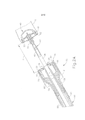
[0015] A Figura 7A ilustra uma vista em perspectiva parcial em se ção transversal de uma bigorna exemplificadora em uma primeira posição na qual a bigorna interage com um conjunto de cabeça de gram- peamento para criar uma anastomose;[0015] Figure 7A illustrates a partial cross-sectional perspective view of an exemplary anvil in a first position in which the anvil interacts with a staple head assembly to create an anastomosis;
[0016] A Figura 7B ilustra uma vista em perspectiva parcial em se ção transversal da bigorna da Figura 7A em uma segunda posição na qual um cabeçote de bigorna foi inclinado na direção contrária a partir de uma união e uma porção de haste de bigorna;[0016] Figure 7B illustrates a partial cross-sectional perspective view of the anvil of Figure 7A in a second position in which an anvil head has been tilted in the opposite direction from a joint and an anvil shank portion;
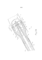
[0017] A Figura 7C ilustra uma vista em perspectiva parcial em se ção transversal da bigorna da Figura 7A em uma terceira posição na qual uma ligação da haste da bigorna está inclinada na direção contrária a partir da porção da haste de bigorna;[0017] Figure 7C illustrates a partial cross-sectional perspective view of the anvil of Figure 7A in a third position in which an anvil shaft connection is slanted in the opposite direction from the anvil shaft portion;
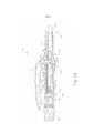
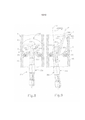
[0018] A Figura 8 ilustra uma vista em perspectiva parcial em se ção transversal de outra bigorna exemplificadora em uma primeira posição na qual a bigorna interage com um conjunto de cabeçote de grampeamento para criar uma anastomose; e[0018] Figure 8 illustrates a partial cross-sectional perspective view of another exemplary anvil in a first position in which the anvil interacts with a clamping head assembly to create an anastomosis; and
[0019] A Figura 9 ilustra uma vista em perspectiva parcial em se ção transversal da bigorna da Figura 8 em uma segunda posição na qual um cabeçote de bigorna é basculado ao redor de um pivô fora de centro de uma porção de haste de bigorna da bigorna.[0019] Figure 9 illustrates a partial cross-sectional perspective view of the anvil of Figure 8 in a second position in which an anvil head is swiveled around an off-center pivot of an anvil shank portion of the anvil .
[0020] Os desenhos não pretendem ser limitadores de modo al gum, e contempla-se que várias modalidades da tecnologia podem ser executadas em uma variedade de outras maneiras, incluindo aquelas não necessariamente representadas nos desenhos. Os desenhos incorporados em anexo e formando uma parte do relatório descritivo ilustram vários aspectos da presente tecnologia, e em conjunto com a descrição servem para explicar os princípios da tecnologia; entende- se, entretanto, que esta tecnologia não se limita precisamente às disposições mostradas.[0020] The drawings are not intended to be limiting in any way, and it is contemplated that various modalities of the technology can be carried out in a variety of other ways, including those not necessarily represented in the drawings. The drawings incorporated in the annex and forming a part of the descriptive report illustrate various aspects of the present technology, and together with the description they serve to explain the principles of the technology; it is understood, however, that this technology is not limited precisely to the provisions shown.
[0021] A seguinte descrição de alguns exemplos da tecnologia não deve ser usada para limitar o seu escopo. Outros exemplos, elementos, aspectos, modalidades e vantagens da tecnologia se tornarão evidentes para os versados na técnica com a descrição a seguir, que é por meio de ilustrações, um dos melhores modos contemplados para realização da tecnologia. Conforme será compreendido, a tecnologia aqui descrita é capaz de outros aspectos diferentes e óbvios, todos sem se afastar da tecnologia. Consequentemente, os desenhos e descrições devem ser considerados como de natureza ilustrativa, e não restritiva.[0021] The following description of some examples of the technology should not be used to limit its scope. Other examples, elements, aspects, modalities and advantages of the technology will become evident to those skilled in the art with the following description, which is through illustrations, one of the best ways contemplated for carrying out the technology. As will be understood, the technology described here is capable of other different and obvious aspects, all without departing from the technology. Consequently, the drawings and descriptions are to be regarded as illustrative in nature and not restrictive.
[0022] As Figuras de 1 a 6 representam um exemplo de instrumen to de grampeamento cirúrgico circular 10, tendo um conjunto de cabeçote de grampeamento 20, um conjunto de haste 60 e um conjunto de cabo atuador 70, cada um dos quais será descrito em detalhes abaixo. O conjunto de haste 60 se estende distalmente a partir do conjunto de cabo atuador 70, e o conjunto de cabeçote de grampeamento 20 é acoplado a uma extremidade distal do conjunto de haste 60. Em resumo, o conjunto de cabo atuador 70 funciona de modo a ativar um acio- nador de grampo 24 do conjunto de cabeçote de grampeamento 20 para conduzir uma pluralidade de grampos 66 para fora do conjunto de cabeçote de grampeamento 20. Para formar grampos finalizados, os grampos 66 são dobrados por uma bigorna 40 que é fixada à extremidade distal do instrumento 10. Consequentemente, o tecido 2 mostrado nas Figuras de 2A a 2C pode ser grampeado com o uso do instrumento 10.[0022] Figures 1 to 6 represent an example of circular
[0023] No presente exemplo, o instrumento 10 compreende um sistema de fechamento e um sistema de disparo. O sistema de fechamento compreende um trocarte 38, um atuador de trocarte 39 e um botão giratório 98. Uma bigorna 40 pode ser acoplada a uma extremidade distal do trocarte 38. O botão giratório 98 tem por finalidade trasladar longitudinalmente o trocarte 38 em relação ao conjunto de cabeçote de grampeamento 20, trasladando assim a bigorna 40 quando mesma está acoplada ao trocarte 38, para grampear o tecido entre a bigorna 40 e o conjunto de cabeçote de grampeamento 20. O sistema de disparo compreende um gatilho 74, um conjunto de acionamento de gatilho 84, um atuador de acionamento 64 e um acionador de grampo 24. O acionador de grampo 24 inclui uma faca 36, configurada para cortar o tecido quando o acionador de grampo 24 é acionado longitudinalmente.Além disso, os grampos 66 são posicionados distalmente a uma pluralidade de elementos de acionamento de grampos 30 do acionador de grampo 24, de modo que o acionador de grampo 24 também conduza os grampos 66 distalmente quando o acionador de grampo 24 é acionado longitudinalmente. Dessa forma, quando o gatilho 74 é acionado e o conjunto de acionamento de gatilho 84 atua o acionador de grampo 24 por meio do atuador de acionamento 64, a faca 36 e os elementos 30 cortam, de maneira substancialmente simultânea, o tecido 2 e conduzem os grampos 66 distalmente em relação ao conjunto de cabeçote de grampeamento 20 e para dentro do tecido. Os componentes e funcionalidades do sistema de fechamento e do sistema de disparo serão, agora, descritos em mais detalhes.[0023] In the present example, the
[0024] Conforme mostrado nas Figuras 1 a 2C, a bigorna 40 é se letivamente acoplável ao instrumento 10, para oferecer uma superfície contra a qual os grampos 66 podem ser dobrados para grampear o material contido entre o conjunto de cabeçote de grampeamento 20 e a bigorna 40. A bigorna 40 do presente exemplo é seletivamente aco- plável a um trocarte ou haste pontiaguda 38, que se estende distal- mente em relação ao conjunto de cabeçote de grampeamento 20. Com referência às Figuras 2A a 2C, a bigorna 40 é seletivamente aco- plável mediante o acoplamento de uma haste proximal 42 da bigorna 40 a uma ponta distal do trocarte 38. A bigorna 40 compreende uma cabeçote de bigorna genericamente circular 48 e uma haste proximal 42 estendendo-se de maneira proximal a partir da cabeçote de bigorna 48. No exemplo mostrado, a haste proximal 42 compreende um elemento tubular 44 que tem presilhas de retenção resilientemente inclinadas 46 para acoplar seletivamente a bigorna 40 ao trocarte 38, embora isso seja meramente opcional, e deve-se compreender que outros recursos de retenção para acoplar a bigorna 40 ao trocarte 38 também podem ser usados. Por exemplo, presilhas em C, grampos, roscas, pinos, adesivos, etc. podem ser empregados para acoplar a bigorna 40 ao trocarte 38. Além disso, embora a bigorna 40 seja descrita como seletivamente acoplável ao trocarte 38, em algumas versões a haste proximal 42 pode incluir um recurso de acoplamento de sentido único de modo que, uma vez fixada, a bigorna 40 não possa ser removida do trocarte 38. Elementos unidirecionais meramente exemplares incluem farpas, botões de pressão unidirecionais, pinças, colares, abas, faixas, etc.. Logicamente ainda outras configurações para acoplar a bigorna 40 ao trocarte 38 serão evidentes ao versado na técnica em vista dos ensinamentos da presente invenção. Por exemplo, o trocarte 38 pode, em vez disso, ser um eixo oco, e a haste proximal 42 pode compreender uma haste afiada que pode ser inserida no eixo oco.[0024] As shown in Figures 1 to 2C, the
[0025] A cabeçote de bigorna 48 do presente exemplo compreen de uma pluralidade de bolsos formadores de grampos 52, formados em uma face proximal 50 da cabeçote de bigorna 48. Consequente- mente, quando a bigorna 40 está na posição fechada e os grampos 66 são conduzidos para fora do conjunto de cabeçote de grampeamento 20 e para dentro dos bolsos formadores de grampos 52, conforme mostrado na Figura 2C, as pernas 68 dos grampos 66 são dobradas para formar grampos finalizados. Deve-se compreender que os bolsos formadores de grampos 52 são meramente opcionais, e podem ser omitidos em algumas versões.[0025] The
[0026] Com a bigorna 40 como componente separado, deve-se compreender que a bigorna 40 pode ser inserida e presa a uma porção de tecido 2 antes de ser acoplada ao conjunto de cabeçote de grampeamento 20. Somente a título de exemplo, a bigorna 40 pode ser inserida e presa a uma primeira porção tubular de tecido 2, enquanto o instrumento 10 é inserido e preso em uma segunda porção tubular de tecido 2. Por exemplo, a primeira porção tubular de tecido 2 pode ser suturada em ou ao redor de uma porção da bigorna 40, e a segunda porção tubular de tecido 2 pode ser suturada em ou ao redor do trocarte 38.[0026] With the
[0027] Conforme mostrado na Figura 2A, a bigorna 40 é, então, acoplada ao trocarte 38. O trocarte 38 do presente exemplo é mostrado em uma posição acionada mais distal. Essa posição estendida do trocarte 38 pode proporcionar uma área maior à qual o tecido 2 pode ser acoplado, antes da fixação da bigorna 40. Além disso, a posição estendida do trocarte 38 pode, também, proporcionar uma fixação mais fácil da bigorna 40 ao trocarte 38. O trocarte 38 inclui, adicionalmente, uma ponta distal afunilada. Essa ponta pode ser capaz de perfuraratravés do tecido, e/ou auxiliar na inserção da bigorna 40 no tro- carte 38, embora a ponta distal afunilada seja meramente opcional. Por exemplo, em outras versões o trocarte 38 pode ter uma ponta não perfurante. Além disso, ou alternativamente, o trocarte 38 pode incluir uma porção magnética não mostrada que pode atrair a bigorna 40 em direção ao trocarte 38. É claro que outras configurações e disposições para a bigorna 40 e o trocarte 38 ficarão evidentes aos versados na técnica, em vista dos ensinamentos aqui contidos.[0027] As shown in Figure 2A, the
[0028] Quando a bigorna 40 é acoplada ao trocarte 38, a distância entre uma face proximal da bigorna 40 e uma face distal do conjunto de cabeçote de grampeamento 20 define uma distância de vão d. O trocarte 38 do presente exemplo é transladável longitudinalmente em relação ao conjunto de cabeçote de grampeamento 20 por meio de um botão de ajuste 98 localizado em uma extremidade proximal do conjunto de cabo atuador 70, conforme será descrito com mais detalhes abaixo. Consequentemente, quando a bigorna 40 é acoplada ao tro- carte 38, a rotação do botão de ajuste 98 amplia ou reduz a distância do vão d, mediante o atuamento da bigorna 40 em relação ao conjunto de cabeçote de grampeamento 20. Por exemplo, conforme mostrado sequencialmente nas Figuras 2A a 2B, a bigorna 40 é mostrada atuando de maneira proximal em relação ao conjunto de cabo atuador 70, a partir de uma posição inicial aberta e para uma posição fechada, reduzindo assim a distância do vão d e a distância entre as duas porções de tecido 2 a serem unidas. Quando a distância do vão dé colocada em um intervalo predeterminado, o conjunto de cabeçote de grampeamento 20 pode ser aquecido, conforme mostrado na Figura 2C, para grampear e cortar o tecido 2 entre a bigorna 40 e o conjunto de cabeçote de grampeamento 20. O conjunto de cabeçote de gram- peamento 20 tem por finalidade grampear e cortar o tecido 2 por um usuário girando um gatilho 74 de conjunto de cabo atuador 70, conformeserá descrito com mais detalhes abaixo.[0028] When the
[0029] Conforme observado acima, a distância do vão dcorres pondeà distância entre a bigorna 40 e o conjunto de cabeçote de grampeamento 20. Quando o instrumento 10 está inserido em um paciente, essa distância do vão d pode não ser facilmente visível. Con- sequentemente, uma barra indicadora móvel 110, mostrada nas Figuras 5 a 6, está disposta de modo a ser visível através de uma janela indicadora 120 posicionada em oposição ao gatilho 74. A barra indicadora 110 tem por finalidade se mover em resposta à rotação do botão de ajuste 98, de modo que a posição da barra indicadora 110 seja representativa da distância do vão d. Conforme mostrado na Figura 6, a janela indicadora 120 compreende, ainda, uma escala 130 que indica que o vão da bigorna está em uma faixa de operação desejada (por exemplo, uma região na cor verde ou "zona verde") e uma representação de compressão do grampo correspondente em cada fim de escala 130. Somente a título de exemplo, conforme mostrado na Figura 6, uma primeira imagem de grampo 132 representa uma grande altura de grampo, enquanto uma segunda imagem de grampo 134 representa uma pequena altura de grampo. Consequentemente, um usuário pode visualizar a posição da bigorna acoplada 40 em relação ao conjunto de cabeçote de grampeamento 20 por meio da barra indicadora 110 e da escala 130. O usuário pode, então, ajustar o posicionamento da bigorna 40 por meio do botão de ajuste 98, conforme necessário.[0029] As noted above, the span distance corresponds to the distance between the
[0030] Com referência novamente às Figuras 2A a 2C, um usuário sutura uma porção do tecido 2 ao redor do elemento tubular 44 de modo que a cabeçote de bigorna 48 esteja situada em uma porção do tecido 2 a ser grampeada. Quando o tecido 2 é fixado à bigorna 40, as presilhas de retenção 46 e uma porção do elemento tubular 44 se projetam a partir do tecido 2, de modo que o usuário possa acoplar a bigorna 40 ao trocarte 38. Com o tecido 2 acoplado ao trocarte 38 e/ou a outra porção do conjunto de cabeçote de grampeamento 20, o usuário fixa a bigorna 40 ao trocarte 38 e aciona a bigorna 40 proximalmente em direção ao conjunto de cabeçote de grampeamento 20, para reduzir a distância do vão d. Quando o instrumento 10 estiver dentro da faixa de operação, o usuário então grampeia as extremidades do teci- do 2, formando assim uma porção tubular do tecido 2 substancialmen-tecontígua.[0030] Referring again to Figures 2A to 2C, a user sutures a portion of the
[0031] A bigorna 40 pode ser ainda construída de acordo com pelo menos alguns dos ensinamentos da patente US n° 5.205.459; patente US n° 5.271.544; patente US n° 5.275.322; patente US n° 5.285.945; patente US n° 5.292.053; patente US n° 5.333.773; patente US n° 5.350.104; patente US n° 5.533.661, cujas revelações estão aqui incorporadas a título de referência; e/ou de acordo com outras configurações, conforme será evidente para um versado na técnica em vista dos ensinamentos da presente invenção.The
[0032] O conjunto de cabeçote de grampeamento 20 do presente exemplo é acoplado a uma extremidade distal do conjunto de haste 60 e compreende um compartimento tubular 22 alojando um acionador de grampo 24 deslizante e uma pluralidade de grampos 66 contidos nas bolsas de grampo 32. Grampos 66 e bolsos de grampo 32 são dispostos em uma matriz circular ao redor do compartimento tubular 22. No presente exemplo, grampos 66 e bolsos de grampo 32 são dispostos em um par de linhas concêntricas anulares de grampos 66 e bolsos de grampo 32. O acionador de grampo 24 tem por finalidade atuar longitudinalmente no interior do compartimento tubular 22, em resposta à rotação do gatilho 74 do conjunto de cabo atuador 70. Conforme mostrado nas Figuras 2A a 2C, o acionador de grampo 24 compreende um elemento cilíndrico alargado tendo uma abertura de trocarte 26, um recesso central 28 e uma pluralidade de elementos 30 dispostos cir- cunferencialmente ao redor do recesso central 28 e se estendendo dis- talmente em relação ao conjunto de haste 60. Cada elemento 30 está configurado para entrar em contato com, e se engatar a, um grampo correspondente 66 da pluralidade de grampos 66 nos bolsos de grampo 32. Consequentemente, quando o acionador de grampo 24 é atua- do em posição distal em relação ao conjunto de cabo atuador 70, cada elemento 30 conduz um grampo correspondente 66 para fora de seu bolso de grampo 32 através de uma abertura de grampo 34 formada em uma extremidade distal do compartimento tubular 22. Como cada elemento 30 se estende a partir do acionador de grampo 24, a pluralidade de grampos 66 é conduzida para fora do conjunto de cabeçote de grampeamento 20 substancialmente ao mesmo tempo. Quando a bigorna 40 está na posição fechada, os grampos 66 são conduzidos em bolsos formadores de grampos 52 para flexão das pernas 68 dos grampos 66, grampeando assim o material localizado entre a bigorna 40 e o conjunto de cabeçote de grampeamento 20. A Figura 3 representa um grampo meramente exemplar 66 conduzido por um elemento 30 em um bolso formador de grampos 32 da bigorna 40 para flexão das pernas 68.[0032] The clamping
[0033] O acionador de grampo 24 inclui adicionalmente uma faca cilíndrica 36 que é coaxial à abertura do trocarte 26 e inserção dos bolsos de grampo 32. No presente exemplo, a faca cilíndrica 36 está disposta dentro do recesso central 28 para trasladar distalmente com o acionador de grampo 24. Quando a bigorna 40 é presa ao trocarte 38, conforme descrito acima, a cabeçote de bigorna 48 fornece uma superfície contra a qual a faca cilíndrica 36 corta o material contido entre a bigorna 40 e o conjunto de cabeçote de grampeamento 20. Em algumasversões, a cabeçote de bigorna 48 pode incluir um recesso não mostrado para a faca cilíndrica 36 para ajudar a cortar o material por exemplo, fornecendo uma borda de corte cooperativa. Além disso, ou alternativamente, a cabeçote de bigorna 48 pode incluir uma ou mais facas de facas cilíndricas opostas não mostradas compensando a faca cilíndrica 36 de modo que possa prover uma ação de corte tipo tesoura. Ainda outras configurações ficarão evidentes aos versados na técnica, em vista dos ensinamentos aqui contidos. O conjunto de cabeço- te de grampeamento 20 funciona, dessa forma, tanto de modo a grampear como de modo a cortar o tecido 2, de maneira substancialmentesimultânea, em resposta ao acionamento pelo conjunto de cabo atuador 70.[0033] The
[0034] Logicamente, o conjunto de cabeçote de grampeamento 20 pode ser adicionalmente construído de acordo com pelo menos alguns dos ensinamentos da patente US n° 5.205.459; patente US n° 5.271.544; patente US n° 5.275.322; patente US n° 5.285.945; patente US n° 5.292.053; patente US n° 5.333.773; patente US n° 5.350.104; patente US n° 5.533.661, cujas revelações estão aqui incorporadas a título de referência; e/ou de acordo com outras configurações, conformeserá evidente para um versado na técnica em vista dos ensinamentos da presente invenção.[0034] Logically, the clamping
[0035] Conforme observado anteriormente, o acionador de grampo 24 inclui uma abertura para trocarte 26. A abertura para trocarte 26 é configurada para permitir que o trocarte 38 deslize longitudinalmente em relação ao conjunto de cabeçote de grampeamento 20 e/ou conjunto de haste 60. Conforme mostrado nas Figuras 2A a 2C, o trocarte 38 é acoplado a um atuador de trocarte 39 de modo que o trocarte 38 possa ser acionado longitudinalmente por meio da rotação do botão giratório 98, conforme será descrito com mais detalhes abaixo em referência ao conjunto de cabo atuador 70. No presente exemplo, o atua- dor de trocarte 39 compreende uma haste alongada, relativamente rígida acoplada ao trocarte 38, embora isso seja meramente opcional. Em algumas versões, o atuador 39 pode compreender um material longitudinalmente rígido enquanto permite flexão lateral de modo que porções do instrumento 10 possam ser seletivamente fletidas ou curvadas durante o uso; ou o instrumento 10 pode incluir um conjunto de haste fletida preparado anteriormente 60. Um material meramente exemplificador é o nitinol. Quando a bigorna 40 está acoplada ao tro- carte 38, o trocarte 38 e a bigorna 40 são transladáveis por meio do atuador 39 para ajustar a distância do vão d entre a bigorna 40 e o conjunto de cabeçote de grampeamento 20. Ainda outras configurações adicionais para que o atuador 39 acione longitudinalmente o tro- carte 38 ficarão evidentes ao versado na técnica, em vista dos ensinamentos aqui contidos.[0035] As noted above, the
[0036] O conjunto do cabeçote de grampeamento 20 e o trocarte 38 são posicionados em uma extremidade distal do conjunto de haste 60, conforme mostrado nas Figuras 2A a 2C. O conjunto de haste 60 do presente exemplo compreende um elemento tubular externo 62 e um atuador de acionamento 64. O elemento tubular externo 62 é acoplado ao revestimento tubular 22 do conjunto de cabeçote de grampe- amento 20 e a um corpo 72 do conjunto de cabo atuador 70, oferecendo assim um apoio mecânico para os componentes atuadores ali contidos. A extremidade proximal do atuador de acionamento 64 é acoplada a um conjunto de acionamento de gatilho 84 do conjunto de cabo atuador 70, descrito a seguir. A extremidade distal do atuador de acionamento 64 é acoplada ao acionador de grampo 24 de modo que a rotação do gatilho 74 acione longitudinalmente o acionador de grampo 24. Conforme mostrado nas Figuras 2A a 2C, o atuador de acionamento 64 compreende um elemento tubular tendo um eixo longitudinal aberto de modo que o acionador 39 acoplado ao trocarte 38 possa acionar longitudinalmente e em relação ao atuador de acionamento 64. Deve-se compreender, é claro, que outros componentes podem estar dispostos no interior do atuador de acionamento 64, conforme ficará evidente ao versado na técnica, em vista dos ensinamentos aqui contidos.[0036] The stapling
[0037] O conjunto de haste 60 pode ser adicionalmente construído de acordo com pelo menos alguns dos ensinamentos da patente US n° 5.205.459; patente US n° 5.271.544; patente US n° 5.275.322; patente US n° 5.285.945; patente US n° 5.292.053; patente US n° 5.333.773; patente US n° 5.350.104; patente US n° 5.533.661, cujas revelações estão aqui incorporadas a título de referência; e/ou de acordo com outrasconfigurações, conforme será evidente para um versado na técnica em vista dos ensinamentos da presente invenção.The
[0038] Agora com referência às Figuras 4A a 5, o conjunto de cabo atuador 70 compreende um corpo 72, um gatilho 74, um recurso de bloqueio 82, um conjunto de acionamento de gatilho 84 e um conjunto de acionamento de trocarte 90. O gatilho 74 do presente exemplo é montado de forma giratória ao corpo 72 e é acoplado ao conjunto de acionamento de gatilho 84 de modo que a rotação do acionamento de gatilho 74 de uma posição não disparada mostrada na Figura 4A a uma posição disparada mostrada na Figura 4B acione o atuador de acionamento 64 descrito acima. Uma mola 78 é acoplada ao corpo 72 e o gatilho 74 para inclinar o gatilho 74 em direção à posição não disparada. O recurso de bloqueio 82 é um elemento pivotante que é acoplado ao corpo 72. Em uma primeira, posição travada, o recurso de bloqueio 82 é girado para cima e na direção contrária do corpo 72 de modo que o recurso de bloqueio 82 engata o gatilho 74 e resiste mecanicamente ao acionamento do gatilho 74 por um usuário. Em uma segunda posição destravada, como a mostrada nas Figuras 1 e 4B, o recurso de bloqueio 82 é girado para baixo de modo que o gatilho 74 pode ser acionado pelo usuário. Consequentemente, com o recurso de bloqueio 82 na segunda posição, o gatilho 74 pode engatar um conjunto de acionamento de gatilho 84 para disparar o instrumento 10.[0038] Now referring to Figures 4A to 5, the
[0039] Conforme mostrado nas Figuras 4A e 4B, o conjunto de acionamento de gatilho 84 da presente exemplo compreende um carro de gatilho deslizante 86 engatado com uma extremidade proximal do atuador de acionamento 64. O carro 86 inclui um conjunto de abas 88 em uma extremidade proximal do carro 86 para reter e engatar um par de braços de gatilho 76 estendendo-se a partir do gatilho 74. Consequentemente, quando o gatilho 74 é girado, o carro 86 é acionado longitudinalmente e transfere o movimento longitudinal para o atuador de acionamento 64. No exemplo mostrado, o carro 86 é acoplado fixamenteà extremidade proximal do atuador de acionamento 64, embora isso seja meramente opcional. De fato, em um exemplo meramente alternativo, o carro 86 pode simplesmente estar em posição limítrofe ao atuador de acionamento 64, enquanto uma mola distal não mostrada inclina o atuador de acionamento 64 de maneira proximal em relação ao conjunto de cabo atuador 70.[0039] As shown in Figures 4A and 4B, the
[0040] O conjunto de atuação do gatilho 84 pode ser adicional menteconstruído de acordo com pelo menos alguns dos ensinamentos da patente US n° 5.205.459; patente US n° 5.271.544; patente US n° 5.275.322; patente US n° 5.285.945; patente US n° 5.292.053; patente US n° 5.333.773; patente US n° 5.350.104; patente US n° 5.533.661, cujas revelações estão aqui incorporadas a título de referência; e/ou de acordo com outras configurações, conforme será evidente para um versado na técnica em vista dos ensinamentos da presente invenção.The
[0041] O corpo 72 também aloja um conjunto de acionamento de trocarte 90 configurado para acionar o trocarte 38 longitudinalmente, em resposta à rotação do botão de ajuste 98. Conforme é melhor mostrado nas Figuras 4A a 5, o conjunto de acionamento de trocarte 90 do presente exemplo compreende o botão de ajuste 98, uma haste estriada 94 e uma luva 92. A haste estriada 94 do presente exemplo está situada em uma extremidade distal do atuador de trocarte 39, embora se deva compreender que a haste estriada 94 e o atuador de trocarte 39 podem ser, alternativamente, componentes separados que se en- gatam para transmitir movimento longitudinal. O botão de ajuste 98 é suportado de maneira giratória pela extremidade proximal do corpo 72, e funciona de modo a girar a luva 92 que está engatada à haste estriada 94 por meio de uma aba interna não mostrada. A haste estriada 94 do presente exemplo compreende um sulco contínuo 96 formado na superfície externa da haste estriada 94. Consequentemente, quando o botão de ajuste 98 é girado, a aba interna se move no interior do sulco 96 e a haste estriada 94 é atuada longitudinalmente em relação à luva 92. Como a haste estriada 94 está situada na extremidade distal do atuador de trocarte 39, girar o botão de ajuste 98 em uma primeira direção faz avançar o atuador de trocarte 39 distalmente em relação ao conjunto de cabo atuador 70. Consequentemente, é aumentada a distância do vão d entre a bigorna 40 e o conjunto de cabeçote de grampeamento 20. Girando-se o botão de ajuste 98 na direção oposta, o atuador de trocarte 39 é acionado de maneira proximal em relação ao conjunto de cabo atuador 70 para reduzir a distância do vão d entre a bigorna 40 e o conjunto de cabeçote de grampeamento 20. Dessa forma, o conjunto de acionamento de trocarte 90 tem por finalidade acionar o trocarte 38 em resposta ao botão de ajuste giratório 98. É claro que outras configurações para o conjunto de acionamento de tro- carte 90 ficarão evidentes ao versado na técnica, em vista dos ensinamentos aqui contidos.[0041]
[0042] O sulco 96 do presente exemplo compreende uma plurali dade de diferentes porções 96A, 96B, 96C que têm um intervalo ou número de sulcos diferente por distância axial. O sulco presente 96 é dividido em uma porção distal 96A, uma porção média 96B e uma porção proximal 96C. Conforme mostrado na Figura 5, uma porção distal 96A compreende um passo fino ou um alto número de sulcos ao longo de uma curta distância axial da haste estriada 94, de modo que é necessário um grande número de rotações do botão de ajuste 98 para percorrer a curta distância axial. A porção média 96B compreende uma seção com intervalo comparavelmente mais grosso ou com menos sulcos por distância axial de modo que relativamente poucas rotações são necessárias para atravessar uma longa distância axial. Consequentemente, a distância do vão d pode ser rapidamente reduzida através de relativamente poucas rotações do botão de ajuste 98. A porção proximal 96C do presente exemplo é substancialmente similar à porção distal 96A e compreende um intervalo fino ou um alto número de sulcos por uma curta distância axial da haste estriada 94 de modo que um grande número de rotações é necessário para atravessar a curta distância axial. A porção proximal 96C do presente exemplo é posicionado na luva 92 quando a bigorna 40 está substancialmente próxima ao conjunto de cabeçote de grampeamento 20 de modo que uma barra indicadora 110 se mova dentro da janela indicadora 120 ao longo da escala 130 para indicar que o vão da bigorna está dentro de uma faixa de operação desejada, conforme será descrito em detalhe abaixo. Consequentemente, quando a aba está dentro da porção proximal 96C do sulco 96, cada rotação do botão de ajuste 98 pode reduzir a distância do vão d a uma pequena quantidade para fornecer uma sintonia fina.The
[0043] O conjunto de atuação do trocarte 90 pode ser adicional menteconstruído de acordo com pelo menos alguns dos ensinamentos da patente US n° 5.205.459; patente US n° 5.271.544; patente US n° 5.275.322; patente US n° 5.285.945; patente US n° 5.292.053; patente US n° 5.333.773; patente US n° 5.350.104; patente US n° 5.533.661, cujas revelações estão aqui incorporadas a título de referência; e/ou de acordo com outras configurações, conforme será evidente para um versado na técnica em vista dos ensinamentos da presente invenção.The
[0044] No exemplo mostrado nas Figuras 4A a 4B, uma presilha em formato de U 100 é fixada a uma porção intermediária do atuador de trocarte 39 localizada distalmente da haste estriada 94. A presilha em formato de U 100 se engata com uma porção de corpo 72 para impedir substancialmente que o atuador de trocarte 39 gire ao redor do seu eixo quando o botão de ajuste 98 é girado. A presilha em formato de U 100 inclui, ainda, uma fenda alongada 102 em cada um de seus lados opostos, para receber um elemento de fixação, como um parafuso, ferrolho, pino, presilha, etc., para ajustar seletivamente a posição longitudinal da fenda alongada 102 da presilha em formato de U 100 em relação ao atuador de trocarte 39, com o propósito de calibrar a barra indicadora 110 em relação à escala 130.[0044] In the example shown in Figures 4A to 4B, a
[0045] Conforme mostrado na Figura 5, o conjunto de cabo atua- dor 70 inclui ainda um bráquete indicador 140 configurado para engatar e girar um indicador 104. O bráquete indicador 140 do presente exemplo é deslizante em relação ao corpo 72 ao longo de um par de fendas formadas no corpo 72. O bráquete indicador 140 compreende uma placa retangular 144, um braço indicador 146 e um flange angular 142. O flange angular 142 é formado na extremidade proximal da placa retangular 144, e inclui uma abertura não mostrada para ser montada de forma deslizante sobre o atuador de trocarte 39 e/ou a haste estriada 94. Uma mola em espiral 150 é interposta entre o flange 142 e uma saliência 152 para inclinar o flange 142 contra a presilha em for-mato de U 100. Consequentemente, quando a presilha em formato de U 100 atua distalmente com o atuador de trocarte 39 e/ou a haste estriada 94, a mola em espiral 150 força o bráquete indicador 140 a mover-se distalmente com a presilha em formato de U 100. Além disso, a presilha em formato de U 100 força o bráquete indicador 140 proxi- malmente em relação à saliência 152, quando o atuador de trocarte 39 e/ou a haste estriada 94 se trasladam proximalmente, comprimindo assim a mola em espiral 150. É claro que se deve compreender que, em algumas versões, o bráquete indicador 140 pode estar preso de maneira fixa ao atuador de trocarte 39 e/ou à haste sulcada 94.[0045] As shown in Figure 5, the
[0046] No presente exemplo, uma porção do recurso de bloqueio 82 fica em contiguidade a uma superfície 141 do bráquete indicador 140, quando o dito bráquete indicador 140 está em uma posição longitudinal que não corresponde a quando o vão da bigorna está dentro de uma faixa de operação desejada por exemplo, uma região colorida verde ou "zona verde". Quando o vão da bigorna estiver dentro de uma faixa de operação desejada (por exemplo, uma região de cor verde ou "zona verde"), o bráquete indicador 140 se afina para fornecer um par de vãos 145 em qualquer lado de um braço indicador 146 que permite que o recurso de bloqueio 82 gire, liberando assim o gatilho 74. Consequentemente, o recurso de bloqueio 82 e o bráquete indicador 140 pode substancialmente impedir um usuário de liberar e operar o gatilho 74 até que a bigorna 40 esteja em uma faixa de operação predetermi-nada. Deve-se compreender, é claro, que o recurso de bloqueio 82 pode ser totalmente omitido em algumas versões.[0046] In the present example, a portion of the locking
[0047] Essa faixa de operação pode ser visualmente comunicada ao usuário por meio de uma barra indicadora 110 de um indicador 104 mostrado contra uma escala 130, descrita brevemente acima. Na extremidade distal do bráquete indicador 140 está um braço indicador projetado distalmente 146 que termina em um dedo projetado lateralmente 148 para controlar o movimento do indicador 104. O braço indicador 146 e o dedo 148, melhor mostrado na Figura 5, são configurados para engate a uma aba 106 do indicador 104, de modo que o indicador 104 seja girado quando o bráquete indicador 140 é acionado longitudinalmente. No presente exemplo, o indicador 104 é acoplado de maneira giratória ao corpo 72 em uma primeira extremidade do indicador 104, embora isso seja meramente opcional, e outros pontos de pivô do indicador 104 ficarão evidentes ao versado na técnica, em vis ta dos ensinamentos aqui contidos. Uma barra indicadora 110 é posicionada na segunda extremidade do indicador 104 de modo que a barra indicadora 110 se mova em resposta ao acionamento do bráquete indicador 140. Consequentemente, conforme discutido acima, a barra indicadora 110 é exibida através de uma janela indicadora 120 contra uma escala 130 (mostrada na Figura 6) para mostrar a distância relativa do vão d entre a bigorna 40 e o conjunto de cabeçote de grampea- mento 20.[0047] This operating range may be visually communicated to the user by means of an
[0048] Logicamente, o bráquete do indicador 140, o indicador 104, e/ou o conjunto de cabo atuador 70 podem ser adicionalmente construídos de acordo com pelo menos alguns dos ensinamentos da patente US n° 5.205.459; patente US n° 5.271.544; patente US n° 5.275.322; patente US n° 5.285.945; patente US n° 5.292.053; patente US n° 5.333.773; patente US n° 5.350.104; patente US n° 5.533.661, cujas revelações estão aqui incorporadas a título de referência; e/ou de acordo com outras configurações, conforme será evidente para um versado na técnica em vista dos ensinamentos da presente invenção.[0048] Logically, the bracket of the
[0049] Conforme descrito acima, uma bigorna como a bigorna 40 da Figura 2A pode ser inserida em um lúmen que forma parte do tecido 2, e pode ser retraída de um local de anastomose, sendo usada, como descrito acima, para grampear porções de tecido 2 para formar a anastomose. Por exemplo, as Figuras 7A a 9 mostram o esôfago superior 4A e o esôfago inferior 4B, que são formados pelo tecido 2. Isso é grampeado em uma anastomose 6. Em uma esofagectomia, por exemplo, um cirurgião pode decidir introduzir uma bigorna de um grampeador circular trans-oralmente e de maneira não traumática. Por exemplo, o cirurgião pode desejar reduzir o trauma que pode ocorrer em uma superfície interna do esôfago através da introdução trans-oral da bigorna, assim como a retração da bigorna, ao impedir que uma borda externa da bigorna interaja com a superfície interna do esôfago 4 durante a inserção e a retração da bigorna. Ou o cirurgião pode querer introduzir a bigorna do grampeador circular de uma maneira não traumática em um procedimento intestinal ou procedimentos similares, conforme ficará evidente aos versados na técnica, em vista dos ensinamentos da presente invenção Por exemplo, a bigorna pode ser introduzida em ou retraída de um lúmen de tecido do corpo de ocorrência natural 2, o qual pode ser o intestino, o esôfago 4 ou alguma outra porção do trato gastrointestinal (GI).[0049] As described above, an anvil such as the
[0050] No que diz respeito a uma introdução trans-oral da bigorna, a bigorna pode ser introduzida trans-oralmente e direcionada para baixo para o esôfago de um paciente 4 até uma primeira posição de sutura mostrada, por exemplo, na Figura 2A sendo que o tecido 2 pode representar o esôfago. A bigorna pode, então, ser suturada na primeira posição de sutura, conforme mostrado na Figura 2A, e conforme descrito acima com relação à bigorna 40. Adicional ou alternativamente, a bigorna pode ser fixada ao tecido 2, como mostrado na Figura 2A, de qualquer maneira que seja adequada, conforme ficará evidente para os versados na técnica, em vista dos ensinamentos da presente invenção. O conjunto de cabeçote de grampeamento 20 pode ser introduzido, por exemplo, através de uma abertura abdominal e ser levado até o esôfago 4 até uma segunda posição de sutura disposta abaixo da primeira posição de sutura. Então, o conjunto de cabeçote de grampeamento 20 pode ser suturado ao tecido 2 conforme descrito acima ou ser fixado de qualquer maneira que seja adequada, conformeficará evidente aos versados na técnica, em vista dos ensinamentos da presente invenção. A bigorna 40 e o conjunto de cabeçote de grampeamento 20 são então operáveis para interagir para separar e grampear o tecido 2, conforme descrito acima, para criar a anastomose 6 (criada por duas porções reconectadas de tecido 2), conforme mostrado nas Figuras 7A a 9, as quais são descritas com mais detalhes adicionalmente abaixo.[0050] With regard to a trans-oral incus introduction, the incus can be trans-orally introduced and directed down into a patient's
[0051] Modificações exemplificadoras adicionais que podem ser fornecidas ao instrumento 10 para reduzir o trauma ao esôfago durante o transporte da bigorna 40, serão descritas com mais detalhes abaixo.Várias maneiras adequadas em que os ensinamentos abaixo podem ser incorporados ao instrumento 10 serão evidentes para os versados na técnica. De modo similar, diversos modos adequados nos quais os ensinamentos abaixo podem ser combinados com diversos ensinamentos das referências citadas na presente invenção, ficarão evidentes aos versados na técnica. Deve ser entendido também que os ensinamentos abaixo não se limitam ao instrumento 10 ou a dispositivos ensinados nas referências mencionadas na presente invenção. Os ensinamentos abaixo podem ser prontamente aplicados a vários outros tipos de instrumentos, incluindo instrumentos que não seriam classificados com grampeadores cirúrgicos. Vários outros dispositivos e configurações adequados em que os ensinamentos abaixo podem ser aplicados serão evidentes aos versados na técnica em vista dos ensinamentos aqui contidos.[0051] Additional exemplary modifications that can be provided to
[0052] Conforme mostrado nas Figuras 7A a 7C, uma primeira bi gorna articulada exemplificadora 240 inclui cabeçote de bigorna 248 e uma haste proximal 242 estendendo-se proximalmente a partir de um cabeçote de bigorna 248. A haste proximal 242 pode ser fixada ao tro- carte 38 de uma maneira, conforme descrita acima, com relação à haste proximal 42 ou como ficará evidente ao versado na técnica, em vista dos ensinamentos da presente invenção. A haste proximal 242 compreende um material flexível, um material rígido, ou qualquer material adequado, conforme ficará evidente ao versado na técnica em vista dos ensinamentos da presente invenção. O cabeçote de bigorna 248 é similar ao cabeçote de bigorna 48, descrito acima, e inclui uma pluralidade de bolsos de formação de grampos não mostrado formados em uma face proximal 250 do cabeçote de bigorna 248. O cabeçote de bigorna 248 opera com grampos 66 de uma maneira similar à descrita acima para o cabeçote de bigorna 48.[0052] As shown in Figures 7A through 7C, an exemplary first hinged
[0053] O cabeçote de bigorna 248 é ligado à haste proximal 242. A haste proximal 242 inclui a ligação 254 e a porção de haste 256. A ligação 254 e a porção de haste 256 são ligadas via pivô de ligação 258. A ligação 254 é giratória em torno de um eixo longitudinal do pivô de ligação 258. O cabeçote de bigorna 248 é ligado à ligação 254 através de um pivô de cabeçote 252. O cabeçote de bigorna 248 é giratório em torno de um eixo longitudinal do pivô do cabeçote 252 na direção da seta A, conforme mostrado na Figura 7B. A ligação 254 da haste proximal 242 é giratória em torno do pivô de ligação 258 na direção da seta (B), conforme mostrado na Figura 7C. O pivô do cabeçote 252, e outros pivôs da presente revelação, podem compreender, por exemplo, pinos recebidos através de canaletas ou outras estruturas adequadas, conforme ficará evidente aos versados na técnica em vista dos ensinamentos da presente invenção.The
[0054] Conforme mostrado na Figura 7B, a haste de acionamento 253 está disposta e pode ser trasladada no interior da haste proximal 242. Quando a haste de acionamento 253 é avançada até uma posição distal, a haste de acionamento 253 engata um ponto fora de centro da face proximal 250 da bigorna 240 com força suficiente para inclinar o cabeçote de bigorna 248 em torno do pivô do cabeçote 252 na direção da seta A. A haste de acionamento 253 mantém o cabeçote de bigorna 248 na posição inclinada enquanto a haste de acionamento 253 está na posição distal. Em algumas versões, a haste de acionamento 253 é retraída proximalmente antes da ligação 254 girar em tor- no do pivô de ligação 258, conforme mostrado na Figura 7C. Em algumas outras versões, a haste de acionamento 253 fica na posição distal quando a ligação 254 gira em torno do pivô de ligação 258. Portando, deve-se entender que a haste de acionamento 253 pode terminar proximalmente distal ao pivô de ligação 258; ou a haste de acionamento pode flexionar através do pivô de ligação 258.[0054] As shown in Figure 7B, the
[0055] Em algumas versões, a posição longitudinal da haste de acionamento 253 em relação ao cabeçote de bigorna 248 tem por base a posição da bigorna 240 em relação ao conjunto de cabeçote de grampeamento 20. Por exemplo, a haste de acionamento 253 pode ser configurada para permanecer na posição distal sempre que a bigorna 240 for desacoplada do trocarte 38 do conjunto de cabeçote de grampeamento 20. Em algumas tais versões, a haste de acionamento 253 pode retrair automaticamente de maneira proximal quando do acoplamento da bigorna 240 ao trocarte 38. Alternativamente, a haste de acionamento 253 pode ser configurada para permanecer na posição distal mesmo após a bigorna 240 ser acoplada ao trocarte 38, quando a bigorna 240 ainda está significativamente espaçada do conjunto de cabeçote de grampeamento 20 por exemplo, antes da bigorna 240 ser extraída em direção a um conjunto de cabeçote de grampea- mento 20 pelo trocarte 38 para prender o tecido entre a bigorna 240 e o conjunto de cabeçote de grampeamento 20, etc.. Em algumas tais versões, um recurso na bigorna 240 e/ou um recurso no conjunto de cabeçote de grampeamento 20 pode ser configurado para retrair a haste de acionamento 253 de maneira proximal, permitindo assim que o cabeçote de bigorna 248 revolva para a posição mostrada na Figura 7A, quando a bigorna 240 está retraída no interior por uma certa distância em relação ao conjunto de cabeçote de grampeamento 20. Por exemplo, um recurso de came da haste proximal 242 pode interagir com um recurso complementar do conjunto de cabeçote de grampea- mento 20 quando a haste proximal 242 está retraída até uma certa posição dentro do conjunto de cabeçote de grampeamento 20. Ao invés de automatizar a retração da haste de acionamento 253, um atuador separado pode se estender ao longo do conjunto de haste 60 até o conjunto do cabo atuador 70, o que permite que o operador avan- ce/retraia seletivamente a haste de acionamento 253 independentemente. Ainda como uma outra variação, a haste de acionamento 253 pode ser integral com a porção de haste 256, e uma combinação de haste de acionamento 253 e de porção de haste 256 pode deslizar seletivamente em relação à ligação 254 e pivotar 258 para avan- çar/retrair seletivamente a haste de acionamento 253. Ainda como outro exemplo meramente ilustrativo, um recurso eletromecânico por exemplo, solenóide, etc. pode ser usado para avançar/retrair seletivamente a haste de acionamento 253 de uma maneira automatizada ou de uma maneira manual/independente. Outras maneiras adequadas nas quais a haste de acionamento 253 pode ser atuada, ficarão evidentes para os versados na técnica em vista dos ensinamentos da presente invenção.[0055] In some versions, the longitudinal position of the
[0056] Em uso, a bigorna 240 é inserida em um lúmen interno do tecido 2 em uma direção de inserção da bigorna. Por exemplo, a bigorna 240 pode ser inserida trans-oralmente no esôfago 4 de um paciente. Antes de a bigorna 240 ser inserida, uma porção do esôfago 4 pode sofrer ressecção e ser removida por exemplo, com o uso de um dispositivo de corte/grampeamento linear do tipo endo-cortador, resultando na separação do esôfago superior 4A do esôfago inferior 4B. A bigorna 240 pode ser inserida no esôfago superior 4A até alcançar a extremidade inferior do esôfago superior 4A, onde o instrumento 10 pode ser usado para unir o esôfago superior 4A e o esôfago inferior 4B através de uma anastomose de extremidade a extremidade 6. A bigorna 240 pode estar nas posições mostradas nas Figuras 7B ou 7C, en- quanto está sendo inserida, por exemplo, e antes da porção de haste 256 ser presa a um trocarte de um conjunto de cabeçote de grampea- mento, como na maneira acima descrita para prender a bigorna 40 ao trocarte 38 e ao conjunto de cabeçote de grampeamento 20. Em algumasversões, garras cirúrgicas convencionais são inseridas através do esôfago 4 para agarrar a porção de haste 256 e, desse modo, puxar a bigorna 240 até o local da anastomose através do esôfago superior 4A.[0056] In use,
[0057] A bigorna 240 pode ser endireitada para uma posição, co mo mostrado na Figura 7A antes de interagir com o conjunto de cabeçote de grampeamento 20 conforme descrito acima. O conjunto de cabeçote de grampeamento 20 é avançado em direção à bigorna 240 através do esôfago inferior 4B em uma direção de grampeamento que é oposta à direção de inserção da bigorna. A porção de haste 256 é acoplada então ao trocarte 38. A força aplicada pelo sistema de disparo e grampeamento, conforme descrito acima, pode endireitar a bigorna 240 e a porção de haste 256 para que elas fiquem na posição mostrada na Figura 7A (por exemplo, quando o instrumento 10 prende o tecido entre o conjunto de cabeçote de grampeamento 20 e o cabeçote de bigorna 248). As posições serão adicionalmente descritas abaixo em relação a uma retração da bigorna 240. A bigorna 240 pode, então, ser usada, conforme descrito acima, para grampear o tecido 2 com grampos 66. A Figura 7A mostra uma posição após a bigorna 240 ter sido usada para grampear o tecido 2 com grampos 66, e após o que, a faca 36 separou o tecido, criando assim uma anastomose segura 6.[0057] The
[0058] Para retrair a bigorna 240, a haste de acionamento 253 é avançada distalmente, fazendo com que o cabeçote de bigorna 248 revolva em torno do pivô do cabeçote 252 na direção da seta A mostrada na Figura 7B. Permanecendo em uma posição estendida, a haste de acionamento 253 ajuda a manter o cabeçote de bigorna 248 na primeira posição girada ou inclinada mostrada na Figura 7B, de uma maneira que ficará evidente para o versado na técnica em vista dos ensinamentos da presente invenção. Por exemplo, a haste de acionamento 253 pode conter uma porção deslocada lateralmente (não mostrada) que se apoia contra a face proximal 250 quando a haste de acionamento 253 está na posição estendida. A porção lateralmente deslocada impede, desse modo, que o cabeçote de bigorna 248 gire de volta para a posição do cabeçote de bigorna 248 mostrada na Figura 7A.[0058] To retract
[0059] A porção de haste 256 é proximalmente retraída ao longo da direção da seta C para retrair a bigorna 240 através do lúmen definido pelo tecido 2 como o esôfago 4. Carga sobre o cabeçote de bigorna 248 oriunda dessa retração pode proporcionar a articulação no pivô de ligação 258. Por exemplo, o cabeçote de bigorna 248 pode estar em posição contígua às paredes da superfície interna do tecido 2, fazendo com que a ligação 254 revolva em torno do pivô de ligação 258 em ângulos de cerca de 30 graus a cerca de 45 graus em relação a uma porção de haste 256 conforme a bigorna 240 é retraída proxi- malmente. Adicionalmente, o cabeçote de bigorna 248 revolve em torno do pivô do cabeçote 252 de modo que o cabeçote de bigorna 248 pode ser retraído dentro de uma passagem interna do tecido 2 com interação mínima com as paredes da superfície interna do tecido 2. Em outras palavras, a inclinação e a rotação descritas acima podem impedir que a borda externa do cabeçote de bigorna 248 raspe a parede interna do esôfago conforme a bigorna 240 é transportada através do esôfago. Na posição mostrada na Figura 7C, por exemplo, a ligação 254 é inclinada com relação à porção de haste 256 e o cabeçote de bigorna 248 é inclinado com relação à ligação 254 para uma posição de retração. Um plano do cabeçote de bigorna 248 mostrado como o plano PP na Figura 7C, define um ângulo agudo com o eixo longitudinal LLA da porção da haste 256 da haste proximal 242, com o vértice VV do ângulo estando posicionado mais baixo do que o pivô do cabeçote 252. Na posição de retração, uma retração da bigorna 240 na direção da seta C evita substancialmente prender a porção mais baixa do cabeçote de bigorna 248, disposta mais próxima ao pivô de ligação 258, com uma superfície interna do tecido 2, e particularmente com bordas da anastomose 6 que são mostradas como estando grampeadas por meio dos grampos 66.[0059]
[0060] A haste de acionamento 253 pode permanecer estendida durante a retração da bigorna 240 conforme descrito acima. Adicionalmente, o cabeçote de bigorna 248 pode ser travado em uma posição, como mostrado na Figura 7B ou na posição, como mostrado na Figura 7C, para facilitar a extração do cabeçote de bigorna 248 da anastomose 6 para reduzir o trauma da anastomose durante a retração da bigorna 240. Por exemplo, uma projeção interna na ligação 254 pode ser recebida em um entalhe interno na porção de haste 256 lateralmente deslocada do pivô de ligação 258 e disposta em um local para travar a ligação 254 em um ângulo de inclinação desejado com re-lação à porção de haste 256. Somente a título de exemplo, a porção de haste 256 pode deslizar seletivamente com relação à ligação 254 e revolver 258 para travar seletivamente o ângulo da ligação 254 no pivô 258.[0060] The
[0061] Em algumas versões, o cabeçote de bigorna 248 é forçado resilientemente a inclinar até a posição mostrada nas Figuras 7B e 7C. Em tais versões, a haste de acionamento 253 pode ser omitida ou ainda ser incluída. Adicionalmente, ou alternativamente, a ligação 254 pode ser forçada resilientemente a inclinar até a posição mostrada na Figura 7C. Diversas maneiras adequadas pelas quais tais inclinações podem ser fornecidas, ficarão evidentes aos versados na técnica em vista dos ensinamentos da presente invenção. Deve-se entender que, em tais versões, a ligação 254 e o cabeçote de bigorna 248 podem, por fim, inclinar até as posições mostradas na Figura 7A uma vez que a bigorna 240 esteja acoplada ao trocarte 38 e a bigorna 240 seja retraída na direção do conjunto de cabeçote de grampeamento 20. Em outras palavras, a passagem axial interna no interior do conjunto de cabeçote de grampeamento 20 pode esticar a ligação 254 e a face distal do conjunto de cabeçote de grampeamento 20 pode endireitar o cabeçote de bigorna 248.[0061] In some versions, the
[0062] Outros modos adequados pelos quais uma bigorna pode incluir uma haste com múltiplos pivôs ficarão evidentes aos versados na técnica em vista dos ensinamentos da presente invenção.[0062] Other suitable ways in which an anvil may include a multi-pivot shank will be apparent to those skilled in the art in view of the teachings of the present invention.
[0063] As Figuras 8 e 9 mostram uma segunda bigorna inclinada exemplificadora 340 que inclui cabeçote de bigorna 348 e uma haste proximal 342 que se estende proximalmente a partir do cabeçote de bigorna 348. A haste proximal 342 pode ser fixada ao trocarte 38 de uma maneira conforme descrito acima, com relação à haste proximal 42 ou conforme ficará evidente para o versado na técnica em vista dos ensinamentos da presente invenção. A haste proximal 342 compreende um material flexível, um material material rígido ou qualquer material adequado, conforme ficará evidente ao versado na técnica em vista dos ensinamentos da presente invenção. O cabeçote de bigorna 348 é similar ao cabeçote de bigorna 48, descrito acima, e inclui uma pluralidade de bolsas de formação de grampo (não mostrado) formadas em uma face proximal 350 do cabeçote de bigorna 348. O cabeçote de bigorna 348 opera com grampos 66 de uma maneira similar à descrita acima para o cabeçote de bigorna 48.[0063] Figures 8 and 9 show a second exemplary
[0064] O cabeçote de bigorna 348 inclui o conector de ligação 351, que conecta o cabeçote de bigorna 348 à haste proximal 342. O cabe- çote de bigorna 348 é ligado à haste proximal 342 através do pivô de cabeçote fora deslocado 352. O cabeçote de bigorna 348 é giratório em torno de um eixo longitudinal do pivô do cabeçote 352 na direção da seta D, conforme mostrado na Figura 9. A haste de acionamento 353 é disposta e pode ser trasladada dentro da haste proximal 342 de uma maneira similar àquela descrita para a haste de acionamento 253. A haste proximal 342 inclui uma primeira porção 354 na qual a haste de acionamento 353 está disposta e uma segunda porção 356 estendendo-se lateralmente a partir de uma extremidade distal da primeira porção 354 da haste proximal 342. O pivô do cabeçote 352 está disposto na segunda porção 356 e está deslocado em relação ao eixo longitudinal da primeira porção 354. O pivô do cabeçote 352 conecta o conector da ligação 351 do cabeçote de bigorna 348 à segunda porção 356 da haste proximal 342, de modo que o conector de ligação 351 e o cabeçote de bigorna 348 sejam giratórios em relação à segunda porção 356 em torno de um eixo longitudinal do pivô do cabeçote 352.[0064] The
[0065] Em uso, a bigorna 340 é inserido em um lúmen interno do tecido 2 (por exemplo, esôfago superior 4A, etc.) em uma direção de inserção da bigorna de uma maneira similar àquela descrita acima para a bigorna 240. A bigorna 340 pode estar em uma posição mostrada na Figura 9 enquanto é inserida, por exemplo. Quando a haste proximal 342 é acoplada ao trocarte 38, a preensão do tecido entre o conjunto de cabeçote de grampeamento 20 e a bigorna 340 irá esticar a bigorna 340 antes de uma atuação de disparo, conforme descrito acima. Dessa forma, a força distribuída pelo sistema de disparo e gram- peamento, conforme descrito acima, endireitará a bigorna 340 para a posição mostrada na Figura 8. A bigorna 340 pode, então, ser usada conforme descrito acima para grampear as superfícies internas do tecido 2. A Figura 8 mostra uma posição após a bigorna 340 ter sido usada para grampear as superfícies internas de um lúmen de tecido 2 com grampos 66 para criar a anastomose 6.[0065] In use,
[0066] Para retrair a bigorna 340, a haste de acionamento 353 é avançada distalmente, fazendo com que o cabeçote de bigorna 348 revolva em torno do pivô do cabeçote 352 na direção da seta D mostrada na Figura 9. A haste de acionamento 353 pode permanecer avançada para ajudar a manter o cabeçote de bigorna 248 na posição inclinada mostrada na Figura 9. Devido ao fato de a segunda porção 356 estar lateralmente deslocada com relação à primeira porção 354, o cabeçote de bigorna 348 é capaz de girar em torno do pivô do cabeçote 352 para uma posição na qual o cabeçote de bigorna 348 esteja a um ângulo obtuso em relação a uma posição inicial do cabeçote de bigorna 348. Em particular, o cabeçote de bigorna 348 gira mais de 90 graus em relação à haste proximal 342 no presente exemplo. Um plano do cabeçote de bigorna 348 ilustrado como plano P na Figura 9 define um ângulo agudo com o eixo longitudinal (LA) da haste proximal 342, com o vértice V do ângulo estando em uma posição mais baixa do que o pivô do cabeçote 352. Dessa forma, uma vez girada, uma extremidade proximal do cabeçote de bigorna 348 é disposta abaixo da segunda porção 356 e entre as extremidades da segunda porção 356 e primeira porção 354 da haste proximal 342.[0066] To retract the
[0067] O cabeçote de bigorna 348 pode ser travável na posição a um ângulo obtuso da Figura 9 para facilitar a extração do cabeçote de bigorna 348 da anastomose 6 de uma maneira similar àquela descrita acima para travar o cabeçote de bigorna 248, conforme ficará evidente para os versados na técnica em vista dos ensinamentos da presente invenção. Por exemplo, uma saliência em uma superfície interna do conector de ligação 351 pode avançar até receber um entalhe complementar disposto em uma superfície interna da segunda porção 356. Adicional ou alternativamente, uma porção que se projeta lateralmente da haste de acionamento 353 pode ser recebida em um entalhe dis- posto em um lado inferior do conector de ligação 351. Outras maneiras adequadas nas quais a haste de acionamento 353 pode ser travada seletivamente na posição distal mostrada na Figura 9 (ou ao menos forçada resilientemente até a posição distal mostrada na Figura 9), ficará evidente para o versado na técnica em vista dos ensinamentos da presente invenção.[0067] The
[0068] A primeira porção 354 é proximalmente retraída para baixo através do esôfago 4 para retrair a bigorna 340 do esôfago de uma maneira, conforme foi descrito acima. A carga sobre o cabeçote de bigorna 348 oriunda dessa retração pode fazer com que a haste proximal 342 incline em uma direção oposta à seta D, enquanto no interior do esôfago 4, de modo que o eixo longitudinal LA da haste proximal 342 seja inclinado em relação ao eixo do esôfago 4. Com o cabeçote de bigorna 348 e a haste proximal 342 inclinada conforme mostrado na Figura 9, o cabeçote de bigorna 348 pode ser retraído para baixo no esôfago 4 com interação mínima entre a borda externa do cabeçote da bigorna 348 e as paredes da superfície interna do esôfago 4. Em outras palavras, a inclinação e a articulação descritas acima, podem impedir que a borda externa do cabeçote de bigorna 348 raspe a parede interna do esôfago conforme a bigorna 340 é transportada através do esôfago.The
[0069] Deve-se compreender que qualquer um ou mais dos ensi namentos, expressões, modalidades, exemplos, etc. aqui descritos podem ser combinados com qualquer um ou mais dos outros ensinamentos, expressões, modalidades, exemplos, etc. que são aqui descritos. Portanto, os ensinamentos, as expressões, as modalidades, os exemplos, etc. descritos acima não devem ser vistos de forma isolada em relação um ao outro. Várias maneiras adequadas, pelas quais os ensinamentos da presente invenção podem ser combinados, serão prontamente evidentes aos versados na técnica tendo em vista os en-sinamentos da presente invenção. Essas modificações e variações são destinadas a estarem incluídas no escopo das reivindicações anexas.[0069] It should be understood that any one or more of the teachings, expressions, modalities, examples, etc. described herein may be combined with any one or more of the other teachings, expressions, modalities, examples, etc. which are described here. Therefore, the teachings, expressions, modalities, examples, etc. described above should not be viewed in isolation from one another. Various suitable ways in which the teachings of the present invention may be combined will be readily apparent to those skilled in the art in view of the teachings of the present invention. These modifications and variations are intended to be included within the scope of the appended claims.
[0070] Entende-se que qualquer patente, publicação, ou outro ma terial de revelação, no todo ou em parte, que diz ser incorporado à presente invenção a título de referência, é incorporado à presente invenção somente se o material incorporado não entrar em conflito com definições, declarações, ou outro material de revelação existentes apresentados nesta revelação. Desse modo, e até onde for necessário, a descrição como explicitamente aqui determinada substitui qualquer material conflitante incorporado aqui a título de referência. Qualquer material, ou porção do mesmo, que são tidos como incorporados a título de referência na presente invenção, mas que entra em conflito com definições, declarações, ou outros materiais de descrição existentes aqui determinados serão aqui incorporados apenas até o ponto em que nenhum conflito surgirá entre o material incorporado e o material de descrição existente.[0070] It is understood that any patent, publication, or other disclosure material, in whole or in part, which is said to be incorporated into the present invention by way of reference, is incorporated into the present invention only if the incorporated material does not enter into conflict with existing definitions, statements, or other disclosure material presented in this disclosure. Accordingly, and to the extent necessary, the description as explicitly stated herein supersedes any conflicting material incorporated herein by reference. Any material, or portion thereof, which is hereby incorporated by reference into the present invention, but which conflicts with existing definitions, statements, or other descriptive materials set forth herein will be incorporated herein only to the extent that no conflict. will appear between the embodied material and the existing descriptive material.
[0071] Versões dos dispositivos descritos acima podem ter aplica ção em tratamentos médicos convencionais e procedimentos conduzidos por um profissional médico, assim como aplicação em tratamentos e procedimentos médicos assistidos por robótica. Somente a título de exemplo, vários ensinamentos da presente invenção podem ser prontamente incorporados a um sistema cirúrgico robótico como o sistema DAVINCI™ pelo Intuitive Surgical, Inc., de Sunnyvale, Califórnia, EUA. De modo similar, os elementos versados na técnica reconhecerão que vários ensinamentos da presente invenção podem ser facilmente combinados com vários ensinamentos da patente US n° 6.783.524, intitulada"Robotic Surgical Tool with Ultrasound Cauterizing and Cutting Instrument", publicada em 31 de agosto de 2004, cuja descrição está aqui incorporada a título de referência.[0071] Versions of the devices described above may have application in conventional medical treatments and procedures conducted by a medical professional, as well as application in medical treatments and procedures assisted by robotics. By way of example only, various teachings of the present invention can be readily incorporated into a robotic surgical system such as the DAVINCI™ system by Intuitive Surgical, Inc., of Sunnyvale, California, USA. Similarly, those skilled in the art will recognize that the various teachings of the present invention can be easily combined with the various teachings of US Patent No. 6,783,524 entitled "Robotic Surgical Tool with Ultrasound Cauterizing and Cutting Instrument", issued August 31 of 2004, the description of which is incorporated herein by reference.
[0072] As versões descritas acima podem ser projetadas para se rem descartadas após um único uso, ou podem ser projetadas para serem usadas múltiplas vezes. As versões podem, em qualquer um ou em ambos os casos, ser recondicionadas para reutilização após pelo menos um uso. O recondicionamento pode incluir qualquer combinação das etapas de desmontagem do dispositivo, seguido de limpeza ou substituição de peças particulares, e remontagem subsequente. Em particular, algumas versões do dispositivo podem ser desmontadas, em qualquer número de peças particulares ou partes do dispositivo podem ser seletivamente substituídas ou removidas em qualquer combinação. Com a limpeza e/ou substituição de partes particulares, algumas versões do dispositivo podem ser remontadas para uso subsequente em uma instalação de recondicionamento, ou por um usuário imediatamente antes de um procedimento cirúrgico. Aqueles versados na técnica entenderão que o recondicionamento de um dispositivo pode utilizar uma variedade de técnicas para desmontagem, limpe- za/substituição e remontagem. O uso de tais técnicas e o dispositivo recondicionado resultante estão todos dentro do escopo do presente pedido.[0072] The versions described above may be designed to be discarded after a single use, or they may be designed to be used multiple times. Versions can, in either or both cases, be reconditioned for reuse after at least one use. Reconditioning can include any combination of steps of disassembling the device, followed by cleaning or replacing particular parts, and subsequent reassembly. In particular, some versions of the device can be disassembled, in any number of particular parts or parts of the device can be selectively replaced or removed in any combination. With cleaning and/or replacement of particular parts, some versions of the device can be reassembled for subsequent use in a reconditioning facility, or by a user immediately prior to a surgical procedure. Those skilled in the art will understand that reconditioning a device can utilize a variety of techniques for disassembly, cleaning/replacement and reassembly. The use of such techniques and the resulting refurbished device are all within the scope of this order.
[0073] Apenas a título de exemplo, as versões aqui descritas po dem ser esterilizadas antes e/ou depois de um procedimento. Em uma técnica de esterilização, o dispositivo é colocado em um recipiente fechado e vedado, como um saco plástico ou de TYVEK. O recipiente e o dispositivo podem então ser colocados em um campo de radiação, como radiação gama, raios X ou elétrons de alta energia, que pode penetrar no recipiente. A radiação pode exterminar bactérias no dispositivo e no recipiente. O dispositivo esterilizado pode então ser guardado em um recipiente estéril para uso posterior. O dispositivo pode também ser esterilizado com o uso de qualquer outra técnica conheci- da, incluindo, mas não se limitando a, radiação beta ou gama, óxido de etileno ou vapor d'água.[0073] By way of example only, the versions described here can be sterilized before and/or after a procedure. In a sterilization technique, the device is placed in a closed, sealed container such as a plastic or TYVEK bag. The container and device can then be placed in a radiation field, such as gamma radiation, X-rays or high energy electrons, which can penetrate the container. Radiation can kill bacteria in the device and container. The sterilized device can then be stored in a sterile container for later use. The device may also be sterilized using any other known technique, including, but not limited to, beta or gamma radiation, ethylene oxide, or water vapor.
[0074] Tendo mostrado e descrito várias modalidades da presente invenção, outras adaptações dos métodos e sistemas descritos na presente invenção podem ser realizados por meio de modificações adequadas por um elemento versado na técnica sem se afastar do escopo da presente invenção. Várias dessas possíveis modificações foram mencionadas, e outras estarão evidentes aos elementos versados na técnica. Por exemplo, os exemplos, modalidades, geometria, materiais, dimensões, proporções, etapas e similares discutidos acima são ilustrativos e não são necessários. Consequentemente, o escopo da presente invenção deve ser considerado de acordo com os termos das reivindicações a seguir e entende-se que ele não está limitado aos detalhes da estrutura e operação mostrados e descritos no relatório descritivo e nos desenhos.[0074] Having shown and described various embodiments of the present invention, other adaptations of the methods and systems described in the present invention can be carried out by means of suitable modifications by a person skilled in the art without departing from the scope of the present invention. Several of these possible modifications have been mentioned, and others will be evident to those skilled in the art. For example, the examples, modalities, geometry, materials, dimensions, proportions, steps and the like discussed above are illustrative and not necessary. Accordingly, the scope of the present invention is to be considered in accordance with the terms of the following claims and it is understood that it is not limited to the details of structure and operation shown and described in the specification and drawings.
Claims (10)
Applications Claiming Priority (3)
| Application Number | Priority Date | Filing Date | Title |
|---|---|---|---|
| US13/688,992 | 2012-11-29 | ||
| US13/688,992 US9498222B2 (en) | 2012-11-29 | 2012-11-29 | Pivoting anvil for surgical circular stapler |
| PCT/US2013/071622 WO2014085303A2 (en) | 2012-11-29 | 2013-11-25 | Pivoting anvil for surgical circular stapler |
Publications (2)
| Publication Number | Publication Date |
|---|---|
| BR112015012227A2 BR112015012227A2 (en) | 2017-07-11 |
| BR112015012227B1 true BR112015012227B1 (en) | 2021-08-31 |
Family
ID=49780348
Family Applications (1)
| Application Number | Title | Priority Date | Filing Date |
|---|---|---|---|
| BR112015012227-2A BR112015012227B1 (en) | 2012-11-29 | 2013-11-25 | CIRCULAR STAPLER APPLIANCE FOR STAPLING TISSUE |
Country Status (9)
| Country | Link |
|---|---|
| US (4) | US9498222B2 (en) |
| EP (2) | EP2931142B1 (en) |
| JP (1) | JP6545620B2 (en) |
| CN (1) | CN104812316B (en) |
| BR (1) | BR112015012227B1 (en) |
| IN (1) | IN2015DN03985A (en) |
| MX (1) | MX357427B (en) |
| RU (1) | RU2651095C2 (en) |
| WO (1) | WO2014085303A2 (en) |
Families Citing this family (72)
| Publication number | Priority date | Publication date | Assignee | Title |
|---|---|---|---|---|
| US10213205B2 (en) * | 2012-07-06 | 2019-02-26 | Covidien Lp | T-slot tilt anvil for circular stapling instrument |
| US9498222B2 (en) * | 2012-11-29 | 2016-11-22 | Ethicon Endo-Surgery, Llc | Pivoting anvil for surgical circular stapler |
| US9597081B2 (en) | 2012-12-17 | 2017-03-21 | Ethicon Endo-Surgery, Llc | Motor driven rotary input circular stapler with modular end effector |
| US9532783B2 (en) | 2012-12-17 | 2017-01-03 | Ethicon Endo-Surgery, Llc | Circular stapler with selectable motorized and manual control, including a control ring |
| US9668740B2 (en) * | 2013-06-14 | 2017-06-06 | Covidien Lp | Anvil assembly with sliding sleeve |
| US9713469B2 (en) | 2013-09-23 | 2017-07-25 | Ethicon Llc | Surgical stapler with rotary cam drive |
| US10729444B2 (en) | 2017-04-28 | 2020-08-04 | Ethicon Llc | Liquid-immune trigger circuit for surgical instrument |
| US20150083772A1 (en) | 2013-09-23 | 2015-03-26 | Ethicon Endo-Surgery, Inc. | Surgical stapler with rotary cam drive and return |
| US10478189B2 (en) | 2015-06-26 | 2019-11-19 | Ethicon Llc | Method of applying an annular array of staples to tissue |
| US10980542B2 (en) | 2016-11-14 | 2021-04-20 | Ethicon Llc | Circular surgical stapler with recessed deck |
| US20180132849A1 (en) | 2016-11-14 | 2018-05-17 | Ethicon Endo-Surgery, Llc | Staple forming pocket configurations for circular surgical stapler anvil |
| US10695068B2 (en) | 2017-04-28 | 2020-06-30 | Ethicon Llc | Hysteresis removal feature in surgical stapling instrument |
| US10709452B2 (en) | 2013-09-23 | 2020-07-14 | Ethicon Llc | Methods and systems for performing circular stapling |
| US9987001B2 (en) | 2015-06-12 | 2018-06-05 | Covidien Lp | Surgical anastomosis apparatus |
| US10905415B2 (en) | 2015-06-26 | 2021-02-02 | Ethicon Llc | Surgical stapler with electromechanical lockout |
| US10271841B2 (en) | 2015-06-26 | 2019-04-30 | Ethicon Llc | Bailout assembly for surgical stapler |
| US10405855B2 (en) | 2015-06-26 | 2019-09-10 | Ethicon Llc | Firing circuit for surgical stapler |
| US10188386B2 (en) | 2015-06-26 | 2019-01-29 | Ethicon Llc | Surgical stapler with anvil state indicator |
| US10226253B2 (en) | 2015-06-26 | 2019-03-12 | Ethicon Llc | Firing assembly for circular stapler |
| US10307157B2 (en) | 2015-06-26 | 2019-06-04 | Ethicon Llc | Surgical stapler with anvil seating detection |
| US10456134B2 (en) | 2015-06-26 | 2019-10-29 | Ethicon Llc | Surgical stapler with reversible motor |
| US10517602B2 (en) | 2015-06-26 | 2019-12-31 | Ethicon Llc | Surgical stapler with reversible polarity |
| US10271842B2 (en) | 2015-06-26 | 2019-04-30 | Ethicon Llc | Anvil stabilization features for surgical stapler |
| US10265066B2 (en) | 2015-06-26 | 2019-04-23 | Ethicon Llc | Surgical stapler with incomplete firing indicator |
| US10194911B2 (en) | 2015-06-26 | 2019-02-05 | Ethicon Llc | Surgical stapler with ready state indicator |
| US10307165B2 (en) | 2015-09-24 | 2019-06-04 | Ethicon Llc | Apparatus and method for radially bunching a bodily lumen |
| US9987013B2 (en) | 2015-09-24 | 2018-06-05 | Ethicon Llc | Surgical staple buttress with magnetic elements |
| US10499909B2 (en) | 2015-09-24 | 2019-12-10 | Ethicon Llc | Apparatus and method for pleating a bodily lumen |
| US10485548B2 (en) | 2015-09-24 | 2019-11-26 | Ethicon Llc | Apparatus and method for forming a staple line with trocar passageway |
| US10492790B2 (en) | 2015-09-24 | 2019-12-03 | Ethicon Llc | Apparatus and method for cinching a straight staple line |
| ES2821891T3 (en) * | 2015-12-07 | 2021-04-28 | Covidien Lp | Anvil Assembly and Delivery System |
| GB201611306D0 (en) | 2016-06-29 | 2016-08-10 | Norwegian Univ Of Science And Tech (Ntnu) | Surgical stapler and a method of stapling tissue |
| US11452522B2 (en) * | 2016-08-15 | 2022-09-27 | Covidien Lp | Circular stapling device with articulating anvil retainer assembly |
| US10542981B2 (en) | 2016-11-14 | 2020-01-28 | Ethicon Llc | Atraumatic stapling head features for circular surgical stapler |
| US10603041B2 (en) | 2016-11-14 | 2020-03-31 | Ethicon Llc | Circular surgical stapler with angularly asymmetric deck features |
| WO2018170831A1 (en) * | 2017-03-23 | 2018-09-27 | Covidien Lp | Circular stapling device with alignment splines |
| US11039839B2 (en) | 2017-09-27 | 2021-06-22 | Cilag Gmbh International | Circular stapling instrument with unitary closure rod |
| US11058428B2 (en) | 2017-09-27 | 2021-07-13 | Cilag Gmbh International | Circular stapling instrument with asymmetric molded shroud components |
| US10758236B2 (en) | 2017-09-27 | 2020-09-01 | Ethicon Llc | Circular stapling instrument with torque limiting feature |
| US10751059B2 (en) | 2017-09-27 | 2020-08-25 | Ethicon Llc | Circular stapling instrument anvil with shank having unitary latches with living hinge |
| US10835256B2 (en) | 2017-09-27 | 2020-11-17 | Ethicon Llc | Circular stapling instrument with firing trigger having integral resilient features |
| BR102019003934A2 (en) | 2018-03-07 | 2019-09-17 | Ethicon Llc | SURGICAL STAPLER WITH REVERSIBLE POLARITY |
| US11207071B2 (en) | 2018-10-15 | 2021-12-28 | Cilag Gmbh International | Dual stage closure system for circular surgical stapler |
| US11134952B2 (en) | 2018-10-15 | 2021-10-05 | Cilag Gmbh International | Dual lever to reduce force to fire in circular surgical stapler |
| US11051819B2 (en) | 2018-10-15 | 2021-07-06 | Cilag Gmbh International | Latch to prevent back-driving of circular surgical stapler |
| US11701109B2 (en) | 2018-12-28 | 2023-07-18 | Cilag Gmbh International | Surgical stapler with sloped staple deck for varying tissue compression |
| US11202635B2 (en) * | 2019-02-04 | 2021-12-21 | Covidien Lp | Programmable distal tilt position of end effector for powered surgical devices |
| US20200281593A1 (en) | 2019-03-08 | 2020-09-10 | Ethicon Llc | Power control circuit for powered surgical stapler |
| US11123075B2 (en) | 2019-03-08 | 2021-09-21 | Cilag Gmbh International | Circular surgical stapler |
| US11116508B2 (en) | 2019-03-08 | 2021-09-14 | Cilag Gmbh International | Electrical potential shifting circuit for powered surgical stapler |
| US11147559B2 (en) | 2019-03-08 | 2021-10-19 | Cilag Gmbh International | Staple height indicator for powered surgical stapler |
| US11224432B2 (en) | 2019-03-08 | 2022-01-18 | Cilag Gmbh International | Timer circuit to control firing of powered surgical stapler |
| US11896233B2 (en) | 2019-05-31 | 2024-02-13 | Covidien Lp | Circular stapling device |
| US11622767B2 (en) | 2020-02-19 | 2023-04-11 | Covidien Lp | Sealed trocar assembly for stapling device |
| US11779343B2 (en) | 2020-02-26 | 2023-10-10 | Covidien Lp | Staple reload assembly with releasable knife |
| US11653925B2 (en) | 2020-05-21 | 2023-05-23 | Covidien Lp | Tissue relaxation monitoring for optimized tissue stapling |
| US11547405B2 (en) | 2020-05-22 | 2023-01-10 | Covidien Lp | Surgical stapling device |
| US11553921B2 (en) | 2020-07-15 | 2023-01-17 | Covidien Lp | Surgical stapling device with flexible shaft |
| US11627966B2 (en) | 2020-08-26 | 2023-04-18 | Covidien Lp | Surgical stapling device |
| US11672533B2 (en) * | 2020-09-08 | 2023-06-13 | Covidien Lp | Laparoscopic transverse surgical stapling system |
| US11801054B2 (en) | 2020-09-22 | 2023-10-31 | Covidien Lp | Surgical stapler with oval tool assembly |
| US11712509B2 (en) | 2020-10-02 | 2023-08-01 | Covidien Lp | Seal assembly for circular stapling instrument |
| US11627967B2 (en) | 2020-11-23 | 2023-04-18 | Covidien Lp | Trans-anastomotic insertion device |
| US11877750B2 (en) | 2021-01-21 | 2024-01-23 | Covidien Lp | Surgical stapler with powered and manual functions |
| US11786241B2 (en) | 2021-02-16 | 2023-10-17 | Covidien Lp | Surgical stapling device including a hydraulic staple formation mechanism |
| US11553920B2 (en) | 2021-05-03 | 2023-01-17 | Covidien Lp | Trocar retainer assembly for surgical stapler |
| US11490894B1 (en) | 2021-05-12 | 2022-11-08 | Covidien Lp | Surgical device with grease filter |
| US11642131B2 (en) | 2021-05-17 | 2023-05-09 | Covidien Lp | Devices and methods for shortening a rectal stump during a lower anterior resection procedure |
| US11612400B2 (en) | 2021-05-24 | 2023-03-28 | Covidien Lp | Trocar assembly with bearing assembly for load sharing |
| US11737759B2 (en) | 2021-08-05 | 2023-08-29 | Covidien Lp | Surgical stapling device accommodating prolapsed tissue |
| US11883028B2 (en) | 2021-09-08 | 2024-01-30 | Covidien Lp | Systems and methods for post-operative anastomotic leak detection |
| US11717299B2 (en) | 2021-10-12 | 2023-08-08 | Covidien Lp | Surgical stapling device with probiotics |
Family Cites Families (62)
| Publication number | Priority date | Publication date | Assignee | Title |
|---|---|---|---|---|
| US4304236A (en) | 1977-05-26 | 1981-12-08 | United States Surgical Corporation | Stapling instrument having an anvil-carrying part of particular geometric shape |
| JPS5578950A (en) | 1978-12-09 | 1980-06-14 | Takasago Ika Kogyo Kk | Suture device of duct portion in body |
| US4505414A (en) | 1983-10-12 | 1985-03-19 | Filipi Charles J | Expandable anvil surgical stapler |
| SU1242140A1 (en) * | 1984-06-29 | 1986-07-07 | Всесоюзный научно-исследовательский и испытательный институт медицинской техники | Surgical apparatus for placing anastomoses on hollow organs |
| US4700703A (en) | 1986-03-27 | 1987-10-20 | Semion Resnick | Cartridge assembly for a surgical stapling instrument |
| US4903697A (en) | 1986-03-27 | 1990-02-27 | Semion Resnick | Cartridge assembly for a surgical stapling instrument |
| US4752024A (en) | 1986-10-17 | 1988-06-21 | Green David T | Surgical fastener and surgical stapling apparatus |
| US4893622A (en) | 1986-10-17 | 1990-01-16 | United States Surgical Corporation | Method of stapling tubular body organs |
| US4805823A (en) | 1988-03-18 | 1989-02-21 | Ethicon, Inc. | Pocket configuration for internal organ staplers |
| US5333773A (en) | 1991-08-23 | 1994-08-02 | Ethicon, Inc. | Sealing means for endoscopic surgical anastomosis stapling instrument |
| US5350104A (en) | 1991-08-23 | 1994-09-27 | Ethicon, Inc. | Sealing means for endoscopic surgical anastomosis stapling instrument |
| GR920100358A (en) | 1991-08-23 | 1993-06-07 | Ethicon Inc | Surgical anastomosis stapling instrument. |
| US5197649A (en) | 1991-10-29 | 1993-03-30 | The Trustees Of Columbia University In The City Of New York | Gastrointestinal endoscoptic stapler |
| US5344059A (en) | 1992-05-19 | 1994-09-06 | United States Surgical Corporation | Surgical apparatus and anvil delivery system therefor |
| US5415334A (en) | 1993-05-05 | 1995-05-16 | Ethicon Endo-Surgery | Surgical stapler and staple cartridge |
| US5597107A (en) | 1994-02-03 | 1997-01-28 | Ethicon Endo-Surgery, Inc. | Surgical stapler instrument |
| US5465895A (en) | 1994-02-03 | 1995-11-14 | Ethicon Endo-Surgery, Inc. | Surgical stapler instrument |
| US5860581A (en) | 1994-03-24 | 1999-01-19 | United States Surgical Corporation | Anvil for circular stapler |
| US5732872A (en) | 1994-06-17 | 1998-03-31 | Heartport, Inc. | Surgical stapling instrument |
| CA2146508C (en) | 1994-08-25 | 2006-11-14 | Robert H. Schnut | Anvil for circular stapler |
| US5632432A (en) | 1994-12-19 | 1997-05-27 | Ethicon Endo-Surgery, Inc. | Surgical instrument |
| US5704534A (en) | 1994-12-19 | 1998-01-06 | Ethicon Endo-Surgery, Inc. | Articulation assembly for surgical instruments |
| US5839639A (en) | 1995-08-17 | 1998-11-24 | Lasersurge, Inc. | Collapsible anvil assembly and applicator instrument |
| US5814055A (en) | 1995-09-19 | 1998-09-29 | Ethicon Endo-Surgery, Inc. | Surgical clamping mechanism |
| US5704898A (en) * | 1995-11-17 | 1998-01-06 | Circon Corporation | Articulation mechanism for an endoscope |
| NL1007349C2 (en) | 1997-10-24 | 1999-04-27 | Suyker Wilhelmus Joseph Leonardus | System for the mechanical production of anastomoses between hollow structures; as well as device and applicator for use therewith. |
| US5951576A (en) | 1998-03-02 | 1999-09-14 | Wakabayashi; Akio | End-to-side vascular anastomosing stapling device |
| US7018387B2 (en) | 1998-10-22 | 2006-03-28 | Innovative Interventional Technologies B.V. | Mechanical anastomosis system for hollow structures |
| US6769590B2 (en) | 2001-04-02 | 2004-08-03 | Susan E. Vresh | Luminal anastomotic device and method |
| US6783524B2 (en) | 2001-04-19 | 2004-08-31 | Intuitive Surgical, Inc. | Robotic surgical tool with ultrasound cauterizing and cutting instrument |
| WO2003030745A1 (en) | 2001-10-05 | 2003-04-17 | Tyco Healthcare Group Lp | Tilt top anvil for a surgical fastener device |
| AU2003269930A1 (en) | 2002-07-31 | 2004-02-25 | Power Medical Interventions, Inc. | Orifice introducer device |
| US7303106B2 (en) * | 2002-10-04 | 2007-12-04 | Tyco Healthcare Group Lp | Surgical stapling device with visual indicator |
| US7143923B2 (en) | 2003-05-20 | 2006-12-05 | Ethicon Endo-Surgery, Inc. | Surgical stapling instrument having a firing lockout for an unclosed anvil |
| US7000818B2 (en) | 2003-05-20 | 2006-02-21 | Ethicon, Endo-Surger, Inc. | Surgical stapling instrument having separate distinct closing and firing systems |
| US7380695B2 (en) | 2003-05-20 | 2008-06-03 | Ethicon Endo-Surgery, Inc. | Surgical stapling instrument having a single lockout mechanism for prevention of firing |
| US7380696B2 (en) | 2003-05-20 | 2008-06-03 | Ethicon Endo-Surgery, Inc. | Articulating surgical stapling instrument incorporating a two-piece E-beam firing mechanism |
| EP1635712B1 (en) * | 2003-06-20 | 2015-09-30 | Covidien LP | Surgical stapling device |
| US7303108B2 (en) | 2003-09-29 | 2007-12-04 | Ethicon Endo-Surgery, Inc. | Surgical stapling instrument incorporating a multi-stroke firing mechanism with a flexible rack |
| US7434715B2 (en) | 2003-09-29 | 2008-10-14 | Ethicon Endo-Surgery, Inc. | Surgical stapling instrument having multistroke firing with opening lockout |
| JP4604040B2 (en) | 2003-10-17 | 2010-12-22 | タイコ ヘルスケア グループ リミテッド パートナーシップ | Surgical stapling device |
| CN100475161C (en) | 2004-03-19 | 2009-04-08 | Tyco医疗健康集团 | Anvil assembly with improved cut ring |
| US7367485B2 (en) | 2004-06-30 | 2008-05-06 | Ethicon Endo-Surgery, Inc. | Surgical stapling instrument incorporating a multistroke firing mechanism having a rotary transmission |
| US7784662B2 (en) * | 2005-02-18 | 2010-08-31 | Ethicon Endo-Surgery, Inc. | Surgical instrument with articulating shaft with single pivot closure and double pivot frame ground |
| US20060201989A1 (en) * | 2005-03-11 | 2006-09-14 | Ojeda Herminio F | Surgical anvil and system for deploying the same |
| US8579176B2 (en) | 2005-07-26 | 2013-11-12 | Ethicon Endo-Surgery, Inc. | Surgical stapling and cutting device and method for using the device |
| US20070194079A1 (en) * | 2005-08-31 | 2007-08-23 | Hueil Joseph C | Surgical stapling device with staple drivers of different height |
| US8540132B2 (en) | 2006-05-16 | 2013-09-24 | Covidien Lp | Tilt anvil assembly |
| US7694041B2 (en) * | 2006-05-19 | 2010-04-06 | Arabella Software Ltd. | Method for managing buffers pool and a system using the method |
| ATE450208T1 (en) | 2006-07-07 | 2009-12-15 | Ethicon Endo Surgery Inc | SURGICAL CLAP SETTING DEVICE |
| US7721930B2 (en) | 2006-11-10 | 2010-05-25 | Thicon Endo-Surgery, Inc. | Disposable cartridge with adhesive for use with a stapling device |
| US20090082785A1 (en) * | 2007-09-24 | 2009-03-26 | Milliman Keith L | Anvil Delivery Device Accessory |
| US8109426B2 (en) | 2008-08-12 | 2012-02-07 | Tyco Healthcare Group Lp | Surgical tilt anvil assembly |
| US9386983B2 (en) * | 2008-09-23 | 2016-07-12 | Ethicon Endo-Surgery, Llc | Robotically-controlled motorized surgical instrument |
| US20110011916A1 (en) | 2009-07-16 | 2011-01-20 | New York University | Anastomosis device |
| US8328062B2 (en) | 2009-07-21 | 2012-12-11 | Covidien Lp | Surgical instrument with curvilinear tissue-contacting surfaces |
| DE102009059196A1 (en) | 2009-12-17 | 2011-06-22 | Aesculap AG, 78532 | Surgical system for connecting body tissue |
| CN102188271B (en) | 2010-03-08 | 2012-10-10 | 北京中法派尔特医疗设备有限公司 | Nail pushing seat assembly capable of inclining laterally and resetting and anastomat adopting same |
| US8496157B2 (en) * | 2011-02-18 | 2013-07-30 | Covidien Lp | Tilting anvil for annular surgical stapler |
| US9089330B2 (en) | 2011-03-14 | 2015-07-28 | Ethicon Endo-Surgery, Inc. | Surgical bowel retractor devices |
| JP5220153B2 (en) * | 2011-03-29 | 2013-06-26 | 富士フイルム株式会社 | Tube anastomosis |
| US9498222B2 (en) * | 2012-11-29 | 2016-11-22 | Ethicon Endo-Surgery, Llc | Pivoting anvil for surgical circular stapler |
-
2012
- 2012-11-29 US US13/688,992 patent/US9498222B2/en active Active
-
2013
- 2013-11-25 EP EP13808330.8A patent/EP2931142B1/en active Active
- 2013-11-25 WO PCT/US2013/071622 patent/WO2014085303A2/en active Application Filing
- 2013-11-25 BR BR112015012227-2A patent/BR112015012227B1/en active IP Right Grant
- 2013-11-25 JP JP2015545140A patent/JP6545620B2/en not_active Expired - Fee Related
- 2013-11-25 CN CN201380062163.6A patent/CN104812316B/en active Active
- 2013-11-25 MX MX2015006801A patent/MX357427B/en active IP Right Grant
- 2013-11-25 IN IN3985DEN2015 patent/IN2015DN03985A/en unknown
- 2013-11-25 EP EP18181393.2A patent/EP3400885A1/en not_active Withdrawn
- 2013-11-25 RU RU2015125314A patent/RU2651095C2/en not_active IP Right Cessation
-
2016
- 2016-10-31 US US15/338,594 patent/US10856875B2/en active Active
-
2020
- 2020-11-05 US US17/090,378 patent/US11690625B2/en active Active
-
2023
- 2023-05-24 US US18/322,847 patent/US20230293180A1/en active Pending
Also Published As
| Publication number | Publication date |
|---|---|
| EP2931142A2 (en) | 2015-10-21 |
| US20210169488A1 (en) | 2021-06-10 |
| WO2014085303A2 (en) | 2014-06-05 |
| US20170042544A1 (en) | 2017-02-16 |
| MX2015006801A (en) | 2015-08-14 |
| US11690625B2 (en) | 2023-07-04 |
| US20140144969A1 (en) | 2014-05-29 |
| EP2931142B1 (en) | 2018-07-04 |
| BR112015012227A2 (en) | 2017-07-11 |
| RU2651095C2 (en) | 2018-04-18 |
| JP6545620B2 (en) | 2019-07-17 |
| RU2015125314A (en) | 2017-01-10 |
| JP2015536209A (en) | 2015-12-21 |
| WO2014085303A3 (en) | 2014-07-31 |
| US9498222B2 (en) | 2016-11-22 |
| US20230293180A1 (en) | 2023-09-21 |
| EP3400885A1 (en) | 2018-11-14 |
| CN104812316B (en) | 2017-10-13 |
| CN104812316A (en) | 2015-07-29 |
| US10856875B2 (en) | 2020-12-08 |
| MX357427B (en) | 2018-07-09 |
| IN2015DN03985A (en) | 2015-10-02 |
Similar Documents
| Publication | Publication Date | Title |
|---|---|---|
| US11690625B2 (en) | Pivoting anvil for surgical circular stapler | |
| US11701120B2 (en) | Circular anvil introduction system with alignment feature | |
| US10743866B2 (en) | Trans-oral circular anvil introduction system with dilation feature | |
| BR112015013158B1 (en) | DEVICE | |
| BR112015014025B1 (en) | CIRCULAR SURGICAL STAPLER FOR FABRIC STAPLING | |
| BR112015012561B1 (en) | STAPLER APPLIANCE FOR FABRIC STAPLING | |
| US10485548B2 (en) | Apparatus and method for forming a staple line with trocar passageway | |
| US9987013B2 (en) | Surgical staple buttress with magnetic elements | |
| BR112020005824A2 (en) | circular stapling instrument with asymmetrical molded wrap components | |
| BR112015014173B1 (en) | CIRCULAR STAPLER FOR FABRIC STAPLING | |
| BR112014016620B1 (en) | SURGICAL STAPLER |
Legal Events
| Date | Code | Title | Description |
|---|---|---|---|
| B06F | Objections, documents and/or translations needed after an examination request according [chapter 6.6 patent gazette] | ||
| B06U | Preliminary requirement: requests with searches performed by other patent offices: procedure suspended [chapter 6.21 patent gazette] | ||
| B09A | Decision: intention to grant [chapter 9.1 patent gazette] | ||
| B16A | Patent or certificate of addition of invention granted [chapter 16.1 patent gazette] |
Free format text: PRAZO DE VALIDADE: 20 (VINTE) ANOS CONTADOS A PARTIR DE 25/11/2013, OBSERVADAS AS CONDICOES LEGAIS. |