BR112015011453B1 - method and device for manufacturing a spirally wound and welded tube - Google Patents
method and device for manufacturing a spirally wound and welded tube Download PDFInfo
- Publication number
- BR112015011453B1 BR112015011453B1 BR112015011453-9A BR112015011453A BR112015011453B1 BR 112015011453 B1 BR112015011453 B1 BR 112015011453B1 BR 112015011453 A BR112015011453 A BR 112015011453A BR 112015011453 B1 BR112015011453 B1 BR 112015011453B1
- Authority
- BR
- Brazil
- Prior art keywords
- profile
- tube
- rollers
- welding
- along
- Prior art date
Links
Images


Classifications
-
- B—PERFORMING OPERATIONS; TRANSPORTING
- B29—WORKING OF PLASTICS; WORKING OF SUBSTANCES IN A PLASTIC STATE IN GENERAL
- B29C—SHAPING OR JOINING OF PLASTICS; SHAPING OF MATERIAL IN A PLASTIC STATE, NOT OTHERWISE PROVIDED FOR; AFTER-TREATMENT OF THE SHAPED PRODUCTS, e.g. REPAIRING
- B29C53/00—Shaping by bending, folding, twisting, straightening or flattening; Apparatus therefor
- B29C53/80—Component parts, details or accessories; Auxiliary operations
- B29C53/82—Cores or mandrels
- B29C53/821—Mandrels especially adapted for winding and joining
- B29C53/825—Mandrels especially adapted for winding and joining for continuous winding
- B29C53/827—Mandrels especially adapted for winding and joining for continuous winding formed by several elements rotating about their own axes
-
- B—PERFORMING OPERATIONS; TRANSPORTING
- B29—WORKING OF PLASTICS; WORKING OF SUBSTANCES IN A PLASTIC STATE IN GENERAL
- B29C—SHAPING OR JOINING OF PLASTICS; SHAPING OF MATERIAL IN A PLASTIC STATE, NOT OTHERWISE PROVIDED FOR; AFTER-TREATMENT OF THE SHAPED PRODUCTS, e.g. REPAIRING
- B29C48/00—Extrusion moulding, i.e. expressing the moulding material through a die or nozzle which imparts the desired form; Apparatus therefor
- B29C48/03—Extrusion moulding, i.e. expressing the moulding material through a die or nozzle which imparts the desired form; Apparatus therefor characterised by the shape of the extruded material at extrusion
- B29C48/09—Articles with cross-sections having partially or fully enclosed cavities, e.g. pipes or channels
-
- B—PERFORMING OPERATIONS; TRANSPORTING
- B29—WORKING OF PLASTICS; WORKING OF SUBSTANCES IN A PLASTIC STATE IN GENERAL
- B29C—SHAPING OR JOINING OF PLASTICS; SHAPING OF MATERIAL IN A PLASTIC STATE, NOT OTHERWISE PROVIDED FOR; AFTER-TREATMENT OF THE SHAPED PRODUCTS, e.g. REPAIRING
- B29C66/00—General aspects of processes or apparatus for joining preformed parts
- B29C66/40—General aspects of joining substantially flat articles, e.g. plates, sheets or web-like materials; Making flat seams in tubular or hollow articles; Joining single elements to substantially flat surfaces
- B29C66/41—Joining substantially flat articles ; Making flat seams in tubular or hollow articles
- B29C66/43—Joining a relatively small portion of the surface of said articles
- B29C66/432—Joining a relatively small portion of the surface of said articles for making tubular articles or closed loops, e.g. by joining several sheets ; for making hollow articles or hollow preforms
- B29C66/4329—Joining a relatively small portion of the surface of said articles for making tubular articles or closed loops, e.g. by joining several sheets ; for making hollow articles or hollow preforms the joint lines being transversal but non-orthogonal with respect to the axis of said tubular articles, i.e. being oblique
-
- B—PERFORMING OPERATIONS; TRANSPORTING
- B29—WORKING OF PLASTICS; WORKING OF SUBSTANCES IN A PLASTIC STATE IN GENERAL
- B29C—SHAPING OR JOINING OF PLASTICS; SHAPING OF MATERIAL IN A PLASTIC STATE, NOT OTHERWISE PROVIDED FOR; AFTER-TREATMENT OF THE SHAPED PRODUCTS, e.g. REPAIRING
- B29C53/00—Shaping by bending, folding, twisting, straightening or flattening; Apparatus therefor
- B29C53/56—Winding and joining, e.g. winding spirally
- B29C53/58—Winding and joining, e.g. winding spirally helically
- B29C53/78—Winding and joining, e.g. winding spirally helically using profiled sheets or strips
-
- B—PERFORMING OPERATIONS; TRANSPORTING
- B29—WORKING OF PLASTICS; WORKING OF SUBSTANCES IN A PLASTIC STATE IN GENERAL
- B29C—SHAPING OR JOINING OF PLASTICS; SHAPING OF MATERIAL IN A PLASTIC STATE, NOT OTHERWISE PROVIDED FOR; AFTER-TREATMENT OF THE SHAPED PRODUCTS, e.g. REPAIRING
- B29C65/00—Joining or sealing of preformed parts, e.g. welding of plastics materials; Apparatus therefor
- B29C65/02—Joining or sealing of preformed parts, e.g. welding of plastics materials; Apparatus therefor by heating, with or without pressure
- B29C65/40—Applying molten plastics, e.g. hot melt
-
- B—PERFORMING OPERATIONS; TRANSPORTING
- B29—WORKING OF PLASTICS; WORKING OF SUBSTANCES IN A PLASTIC STATE IN GENERAL
- B29C—SHAPING OR JOINING OF PLASTICS; SHAPING OF MATERIAL IN A PLASTIC STATE, NOT OTHERWISE PROVIDED FOR; AFTER-TREATMENT OF THE SHAPED PRODUCTS, e.g. REPAIRING
- B29C66/00—General aspects of processes or apparatus for joining preformed parts
- B29C66/01—General aspects dealing with the joint area or with the area to be joined
- B29C66/05—Particular design of joint configurations
- B29C66/10—Particular design of joint configurations particular design of the joint cross-sections
- B29C66/11—Joint cross-sections comprising a single joint-segment, i.e. one of the parts to be joined comprising a single joint-segment in the joint cross-section
- B29C66/112—Single lapped joints
- B29C66/1122—Single lap to lap joints, i.e. overlap joints
-
- B—PERFORMING OPERATIONS; TRANSPORTING
- B29—WORKING OF PLASTICS; WORKING OF SUBSTANCES IN A PLASTIC STATE IN GENERAL
- B29C—SHAPING OR JOINING OF PLASTICS; SHAPING OF MATERIAL IN A PLASTIC STATE, NOT OTHERWISE PROVIDED FOR; AFTER-TREATMENT OF THE SHAPED PRODUCTS, e.g. REPAIRING
- B29C66/00—General aspects of processes or apparatus for joining preformed parts
- B29C66/01—General aspects dealing with the joint area or with the area to be joined
- B29C66/05—Particular design of joint configurations
- B29C66/20—Particular design of joint configurations particular design of the joint lines, e.g. of the weld lines
- B29C66/23—Particular design of joint configurations particular design of the joint lines, e.g. of the weld lines said joint lines being multiple and parallel or being in the form of tessellations
- B29C66/232—Particular design of joint configurations particular design of the joint lines, e.g. of the weld lines said joint lines being multiple and parallel or being in the form of tessellations said joint lines being multiple and parallel, i.e. the joint being formed by several parallel joint lines
-
- B—PERFORMING OPERATIONS; TRANSPORTING
- B29—WORKING OF PLASTICS; WORKING OF SUBSTANCES IN A PLASTIC STATE IN GENERAL
- B29C—SHAPING OR JOINING OF PLASTICS; SHAPING OF MATERIAL IN A PLASTIC STATE, NOT OTHERWISE PROVIDED FOR; AFTER-TREATMENT OF THE SHAPED PRODUCTS, e.g. REPAIRING
- B29C66/00—General aspects of processes or apparatus for joining preformed parts
- B29C66/01—General aspects dealing with the joint area or with the area to be joined
- B29C66/345—Progressively making the joint, e.g. starting from the middle
-
- B—PERFORMING OPERATIONS; TRANSPORTING
- B29—WORKING OF PLASTICS; WORKING OF SUBSTANCES IN A PLASTIC STATE IN GENERAL
- B29C—SHAPING OR JOINING OF PLASTICS; SHAPING OF MATERIAL IN A PLASTIC STATE, NOT OTHERWISE PROVIDED FOR; AFTER-TREATMENT OF THE SHAPED PRODUCTS, e.g. REPAIRING
- B29C66/00—General aspects of processes or apparatus for joining preformed parts
- B29C66/50—General aspects of joining tubular articles; General aspects of joining long products, i.e. bars or profiled elements; General aspects of joining single elements to tubular articles, hollow articles or bars; General aspects of joining several hollow-preforms to form hollow or tubular articles
- B29C66/51—Joining tubular articles, profiled elements or bars; Joining single elements to tubular articles, hollow articles or bars; Joining several hollow-preforms to form hollow or tubular articles
- B29C66/52—Joining tubular articles, bars or profiled elements
- B29C66/524—Joining profiled elements
-
- B—PERFORMING OPERATIONS; TRANSPORTING
- B29—WORKING OF PLASTICS; WORKING OF SUBSTANCES IN A PLASTIC STATE IN GENERAL
- B29C—SHAPING OR JOINING OF PLASTICS; SHAPING OF MATERIAL IN A PLASTIC STATE, NOT OTHERWISE PROVIDED FOR; AFTER-TREATMENT OF THE SHAPED PRODUCTS, e.g. REPAIRING
- B29C66/00—General aspects of processes or apparatus for joining preformed parts
- B29C66/50—General aspects of joining tubular articles; General aspects of joining long products, i.e. bars or profiled elements; General aspects of joining single elements to tubular articles, hollow articles or bars; General aspects of joining several hollow-preforms to form hollow or tubular articles
- B29C66/63—Internally supporting the article during joining
-
- B—PERFORMING OPERATIONS; TRANSPORTING
- B29—WORKING OF PLASTICS; WORKING OF SUBSTANCES IN A PLASTIC STATE IN GENERAL
- B29C—SHAPING OR JOINING OF PLASTICS; SHAPING OF MATERIAL IN A PLASTIC STATE, NOT OTHERWISE PROVIDED FOR; AFTER-TREATMENT OF THE SHAPED PRODUCTS, e.g. REPAIRING
- B29C66/00—General aspects of processes or apparatus for joining preformed parts
- B29C66/70—General aspects of processes or apparatus for joining preformed parts characterised by the composition, physical properties or the structure of the material of the parts to be joined; Joining with non-plastics material
- B29C66/73—General aspects of processes or apparatus for joining preformed parts characterised by the composition, physical properties or the structure of the material of the parts to be joined; Joining with non-plastics material characterised by the intensive physical properties of the material of the parts to be joined, by the optical properties of the material of the parts to be joined, by the extensive physical properties of the parts to be joined, by the state of the material of the parts to be joined or by the material of the parts to be joined being a thermoplastic or a thermoset
- B29C66/739—General aspects of processes or apparatus for joining preformed parts characterised by the composition, physical properties or the structure of the material of the parts to be joined; Joining with non-plastics material characterised by the intensive physical properties of the material of the parts to be joined, by the optical properties of the material of the parts to be joined, by the extensive physical properties of the parts to be joined, by the state of the material of the parts to be joined or by the material of the parts to be joined being a thermoplastic or a thermoset characterised by the material of the parts to be joined being a thermoplastic or a thermoset
- B29C66/7392—General aspects of processes or apparatus for joining preformed parts characterised by the composition, physical properties or the structure of the material of the parts to be joined; Joining with non-plastics material characterised by the intensive physical properties of the material of the parts to be joined, by the optical properties of the material of the parts to be joined, by the extensive physical properties of the parts to be joined, by the state of the material of the parts to be joined or by the material of the parts to be joined being a thermoplastic or a thermoset characterised by the material of the parts to be joined being a thermoplastic or a thermoset characterised by the material of at least one of the parts being a thermoplastic
- B29C66/73921—General aspects of processes or apparatus for joining preformed parts characterised by the composition, physical properties or the structure of the material of the parts to be joined; Joining with non-plastics material characterised by the intensive physical properties of the material of the parts to be joined, by the optical properties of the material of the parts to be joined, by the extensive physical properties of the parts to be joined, by the state of the material of the parts to be joined or by the material of the parts to be joined being a thermoplastic or a thermoset characterised by the material of the parts to be joined being a thermoplastic or a thermoset characterised by the material of at least one of the parts being a thermoplastic characterised by the materials of both parts being thermoplastics
-
- B—PERFORMING OPERATIONS; TRANSPORTING
- B29—WORKING OF PLASTICS; WORKING OF SUBSTANCES IN A PLASTIC STATE IN GENERAL
- B29C—SHAPING OR JOINING OF PLASTICS; SHAPING OF MATERIAL IN A PLASTIC STATE, NOT OTHERWISE PROVIDED FOR; AFTER-TREATMENT OF THE SHAPED PRODUCTS, e.g. REPAIRING
- B29C66/00—General aspects of processes or apparatus for joining preformed parts
- B29C66/80—General aspects of machine operations or constructions and parts thereof
- B29C66/81—General aspects of the pressing elements, i.e. the elements applying pressure on the parts to be joined in the area to be joined, e.g. the welding jaws or clamps
- B29C66/814—General aspects of the pressing elements, i.e. the elements applying pressure on the parts to be joined in the area to be joined, e.g. the welding jaws or clamps characterised by the design of the pressing elements, e.g. of the welding jaws or clamps
- B29C66/8145—General aspects of the pressing elements, i.e. the elements applying pressure on the parts to be joined in the area to be joined, e.g. the welding jaws or clamps characterised by the design of the pressing elements, e.g. of the welding jaws or clamps characterised by the constructional aspects of the pressing elements, e.g. of the welding jaws or clamps
- B29C66/81463—General aspects of the pressing elements, i.e. the elements applying pressure on the parts to be joined in the area to be joined, e.g. the welding jaws or clamps characterised by the design of the pressing elements, e.g. of the welding jaws or clamps characterised by the constructional aspects of the pressing elements, e.g. of the welding jaws or clamps comprising a plurality of single pressing elements, e.g. a plurality of sonotrodes, or comprising a plurality of single counter-pressing elements, e.g. a plurality of anvils, said plurality of said single elements being suitable for making a single joint
- B29C66/81465—General aspects of the pressing elements, i.e. the elements applying pressure on the parts to be joined in the area to be joined, e.g. the welding jaws or clamps characterised by the design of the pressing elements, e.g. of the welding jaws or clamps characterised by the constructional aspects of the pressing elements, e.g. of the welding jaws or clamps comprising a plurality of single pressing elements, e.g. a plurality of sonotrodes, or comprising a plurality of single counter-pressing elements, e.g. a plurality of anvils, said plurality of said single elements being suitable for making a single joint one placed behind the other in a single row in the feed direction
-
- B—PERFORMING OPERATIONS; TRANSPORTING
- B29—WORKING OF PLASTICS; WORKING OF SUBSTANCES IN A PLASTIC STATE IN GENERAL
- B29C—SHAPING OR JOINING OF PLASTICS; SHAPING OF MATERIAL IN A PLASTIC STATE, NOT OTHERWISE PROVIDED FOR; AFTER-TREATMENT OF THE SHAPED PRODUCTS, e.g. REPAIRING
- B29C66/00—General aspects of processes or apparatus for joining preformed parts
- B29C66/80—General aspects of machine operations or constructions and parts thereof
- B29C66/83—General aspects of machine operations or constructions and parts thereof characterised by the movement of the joining or pressing tools
- B29C66/834—General aspects of machine operations or constructions and parts thereof characterised by the movement of the joining or pressing tools moving with the parts to be joined
- B29C66/8341—Roller, cylinder or drum types; Band or belt types; Ball types
- B29C66/83411—Roller, cylinder or drum types
-
- B—PERFORMING OPERATIONS; TRANSPORTING
- B29—WORKING OF PLASTICS; WORKING OF SUBSTANCES IN A PLASTIC STATE IN GENERAL
- B29C—SHAPING OR JOINING OF PLASTICS; SHAPING OF MATERIAL IN A PLASTIC STATE, NOT OTHERWISE PROVIDED FOR; AFTER-TREATMENT OF THE SHAPED PRODUCTS, e.g. REPAIRING
- B29C66/00—General aspects of processes or apparatus for joining preformed parts
- B29C66/90—Measuring or controlling the joining process
- B29C66/92—Measuring or controlling the joining process by measuring or controlling the pressure, the force, the mechanical power or the displacement of the joining tools
- B29C66/922—Measuring or controlling the joining process by measuring or controlling the pressure, the force, the mechanical power or the displacement of the joining tools by measuring the pressure, the force, the mechanical power or the displacement of the joining tools
- B29C66/9221—Measuring or controlling the joining process by measuring or controlling the pressure, the force, the mechanical power or the displacement of the joining tools by measuring the pressure, the force, the mechanical power or the displacement of the joining tools by measuring the pressure, the force or the mechanical power
-
- B—PERFORMING OPERATIONS; TRANSPORTING
- B29—WORKING OF PLASTICS; WORKING OF SUBSTANCES IN A PLASTIC STATE IN GENERAL
- B29C—SHAPING OR JOINING OF PLASTICS; SHAPING OF MATERIAL IN A PLASTIC STATE, NOT OTHERWISE PROVIDED FOR; AFTER-TREATMENT OF THE SHAPED PRODUCTS, e.g. REPAIRING
- B29C66/00—General aspects of processes or apparatus for joining preformed parts
- B29C66/90—Measuring or controlling the joining process
- B29C66/92—Measuring or controlling the joining process by measuring or controlling the pressure, the force, the mechanical power or the displacement of the joining tools
- B29C66/924—Measuring or controlling the joining process by measuring or controlling the pressure, the force, the mechanical power or the displacement of the joining tools by controlling or regulating the pressure, the force, the mechanical power or the displacement of the joining tools
- B29C66/9241—Measuring or controlling the joining process by measuring or controlling the pressure, the force, the mechanical power or the displacement of the joining tools by controlling or regulating the pressure, the force, the mechanical power or the displacement of the joining tools by controlling or regulating the pressure, the force or the mechanical power
- B29C66/92431—Measuring or controlling the joining process by measuring or controlling the pressure, the force, the mechanical power or the displacement of the joining tools by controlling or regulating the pressure, the force, the mechanical power or the displacement of the joining tools by controlling or regulating the pressure, the force or the mechanical power the pressure, the force or the mechanical power being kept constant over time
-
- B—PERFORMING OPERATIONS; TRANSPORTING
- B29—WORKING OF PLASTICS; WORKING OF SUBSTANCES IN A PLASTIC STATE IN GENERAL
- B29C—SHAPING OR JOINING OF PLASTICS; SHAPING OF MATERIAL IN A PLASTIC STATE, NOT OTHERWISE PROVIDED FOR; AFTER-TREATMENT OF THE SHAPED PRODUCTS, e.g. REPAIRING
- B29C66/00—General aspects of processes or apparatus for joining preformed parts
- B29C66/90—Measuring or controlling the joining process
- B29C66/92—Measuring or controlling the joining process by measuring or controlling the pressure, the force, the mechanical power or the displacement of the joining tools
- B29C66/924—Measuring or controlling the joining process by measuring or controlling the pressure, the force, the mechanical power or the displacement of the joining tools by controlling or regulating the pressure, the force, the mechanical power or the displacement of the joining tools
- B29C66/9261—Measuring or controlling the joining process by measuring or controlling the pressure, the force, the mechanical power or the displacement of the joining tools by controlling or regulating the pressure, the force, the mechanical power or the displacement of the joining tools by controlling or regulating the displacement of the joining tools
-
- B—PERFORMING OPERATIONS; TRANSPORTING
- B29—WORKING OF PLASTICS; WORKING OF SUBSTANCES IN A PLASTIC STATE IN GENERAL
- B29C—SHAPING OR JOINING OF PLASTICS; SHAPING OF MATERIAL IN A PLASTIC STATE, NOT OTHERWISE PROVIDED FOR; AFTER-TREATMENT OF THE SHAPED PRODUCTS, e.g. REPAIRING
- B29C66/00—General aspects of processes or apparatus for joining preformed parts
- B29C66/90—Measuring or controlling the joining process
- B29C66/96—Measuring or controlling the joining process characterised by the method for implementing the controlling of the joining process
- B29C66/961—Measuring or controlling the joining process characterised by the method for implementing the controlling of the joining process involving a feedback loop mechanism, e.g. comparison with a desired value
-
- F—MECHANICAL ENGINEERING; LIGHTING; HEATING; WEAPONS; BLASTING
- F16—ENGINEERING ELEMENTS AND UNITS; GENERAL MEASURES FOR PRODUCING AND MAINTAINING EFFECTIVE FUNCTIONING OF MACHINES OR INSTALLATIONS; THERMAL INSULATION IN GENERAL
- F16L—PIPES; JOINTS OR FITTINGS FOR PIPES; SUPPORTS FOR PIPES, CABLES OR PROTECTIVE TUBING; MEANS FOR THERMAL INSULATION IN GENERAL
- F16L9/00—Rigid pipes
- F16L9/12—Rigid pipes of plastics with or without reinforcement
-
- F—MECHANICAL ENGINEERING; LIGHTING; HEATING; WEAPONS; BLASTING
- F16—ENGINEERING ELEMENTS AND UNITS; GENERAL MEASURES FOR PRODUCING AND MAINTAINING EFFECTIVE FUNCTIONING OF MACHINES OR INSTALLATIONS; THERMAL INSULATION IN GENERAL
- F16L—PIPES; JOINTS OR FITTINGS FOR PIPES; SUPPORTS FOR PIPES, CABLES OR PROTECTIVE TUBING; MEANS FOR THERMAL INSULATION IN GENERAL
- F16L9/00—Rigid pipes
- F16L9/16—Rigid pipes wound from sheets or strips, with or without reinforcement
-
- B—PERFORMING OPERATIONS; TRANSPORTING
- B29—WORKING OF PLASTICS; WORKING OF SUBSTANCES IN A PLASTIC STATE IN GENERAL
- B29C—SHAPING OR JOINING OF PLASTICS; SHAPING OF MATERIAL IN A PLASTIC STATE, NOT OTHERWISE PROVIDED FOR; AFTER-TREATMENT OF THE SHAPED PRODUCTS, e.g. REPAIRING
- B29C53/00—Shaping by bending, folding, twisting, straightening or flattening; Apparatus therefor
- B29C53/80—Component parts, details or accessories; Auxiliary operations
- B29C53/82—Cores or mandrels
-
- B—PERFORMING OPERATIONS; TRANSPORTING
- B29—WORKING OF PLASTICS; WORKING OF SUBSTANCES IN A PLASTIC STATE IN GENERAL
- B29K—INDEXING SCHEME ASSOCIATED WITH SUBCLASSES B29B, B29C OR B29D, RELATING TO MOULDING MATERIALS OR TO MATERIALS FOR MOULDS, REINFORCEMENTS, FILLERS OR PREFORMED PARTS, e.g. INSERTS
- B29K2101/00—Use of unspecified macromolecular compounds as moulding material
- B29K2101/12—Thermoplastic materials
-
- B—PERFORMING OPERATIONS; TRANSPORTING
- B29—WORKING OF PLASTICS; WORKING OF SUBSTANCES IN A PLASTIC STATE IN GENERAL
- B29L—INDEXING SCHEME ASSOCIATED WITH SUBCLASS B29C, RELATING TO PARTICULAR ARTICLES
- B29L2023/00—Tubular articles
- B29L2023/22—Tubes or pipes, i.e. rigid
-
- B—PERFORMING OPERATIONS; TRANSPORTING
- B29—WORKING OF PLASTICS; WORKING OF SUBSTANCES IN A PLASTIC STATE IN GENERAL
- B29L—INDEXING SCHEME ASSOCIATED WITH SUBCLASS B29C, RELATING TO PARTICULAR ARTICLES
- B29L2024/00—Articles with hollow walls
Abstract
MÉTODO E DISPOSITIVO PARA FABRICAÇÃO DE UM TUBO ENROLADO E SOLDADO EM FORMA DE ESPIRAL. A presente invenção está correlacionada a um método e dispositivo para fabricação de um tubo enrolado e soldado em forma de espiral. Um perfil termoplástico (1) é deslizado ao longo de um percurso em um dispositivo de deslizamento (12, 13), disposto numa direção axial do dito tubo e definindo uma superfície de enrolamento de formato cilíndrico, com um diâmetro correspondente ao diâmetro interno do tubo a ser .fabricado. 0 perfil (1) é direcionado ao longo de um percurso em espiral (S), na direção de uma volta anterior do dito perfil, por meio de rolos radiais (10) espaçados ao longo do dito percurso em espiral, mediante ajuste da posição (d) dos rolos. Arestas opostas (la, lb) das ditas voltas do perfil são soldadas, mediante provisão de uma massa de soldagem extrudada (6) entre as ditas voltas do perfil. O tubo soldado (4) é alimentado a partir da plataforma de soldagem por meio de rolos (10), mediante deslizamento do mesmo sobre um suporte rotativo (2A).METHOD AND DEVICE FOR THE MANUFACTURING OF A SPIRAL WINDED AND WELDED TUBE. The present invention relates to a method and device for manufacturing a spirally wound and welded tube. A thermoplastic profile (1) is slid along a path in a sliding device (12, 13), disposed in an axial direction of said tube and defining a cylindrical-shaped winding surface, with a diameter corresponding to the inner diameter of the tube. to be .manufactured. The profile (1) is directed along a spiral path (S), in the direction of an anterior turn of said profile, by means of radial rollers (10) spaced along said spiral path, by adjusting the position ( d) of the rollers. Opposite edges (1a, lb) of said profile turns are welded, by providing an extruded welding mass (6) between said profile turns. The welded tube (4) is fed from the welding platform by means of rollers (10), by sliding it on a rotating support (2A).
Description
[001] A presente invenção está correlacionada a um método e dispositivo para fabricação de um tubo enrolado e soldado em forma de espiral. Tubos soldados enrolados em forma de espiral do tipo em questão são divulgados nas Patentes Europeias de Nos. 714.346 e 1.237.708. Nesses casos, uma única e confiável soldagem é feita em uma operação exterior a uma extrusora.[001] The present invention is related to a method and device for manufacturing a coiled and welded tube in a spiral shape. Spiral-wound welded tubes of the type in question are disclosed in European Patent Nos. 714,346 and 1,237,708. In these cases, a single, reliable weld is done in an operation outside an extruder.
[002] As exigências para satisfatórias costuras de solda em materiais termoplásticos incluem que as superfícies a serem soldadas sejam uniformemente aquecidas a uma correta temperatura, e que as superfícies a serem soldadas sejam pressionadas entre si.[002] The requirements for satisfactory welding seams in thermoplastic materials include that the surfaces to be welded are uniformly heated to a correct temperature, and that the surfaces to be welded are pressed together.
[003] Nessas soluções anteriores, a soldagem foi realizada por meio de um tambor girando ao longo de toda a sua extensão, em torno do qual um perfil termoplástico é enrolado e sobre o qual a soldagem é realizada. A junta da solda sobre a superfície externa do tubo é alisada quando o tubo se dispõe contra o tambor. Isso é feito ao permitir um corpo de alisamento estacionário se dispor contra e deslizar ao longo da junta de solda aquecida, durante o movimento de rotação do tubo. A junta de solda no interior do tubo foi formada contra o tambor rotativo, como no caso da citação feita no documento EP 714346, ou ambas as juntas de solda interna e externa são alisadas por meio de aplicação de calor extra e de corpos estacionários se dispondo contra a junta de solda, conforme descrito no documento EP 1.237.708.[003] In these previous solutions, welding was performed by means of a drum rotating along its entire length, around which a thermoplastic profile is wrapped and on which the welding is performed. The weld joint on the outer surface of the tube is smoothed when the tube rests against the drum. This is done by allowing a stationary smoothing body to lay against and slide along the heated weld joint during the tube's rotational movement. The weld joint inside the tube has been formed against the rotating drum, as in the case of the quote made in EP 714346, or both the internal and external weld joints are smoothed by applying extra heat and stationary bodies if available against the solder joint as described in EP 1,237,708.
[004] As soluções anteriores solucionaram o problema mediante aplicação de massa de soldagem e alisamento das superfícies de costura de solda de uma maneira bastante satisfatória. Entretanto, o controle das forças através das quais os perfis a serem soldados são impulsionados e costurados juntos foi considerado difícil, na medida em que isso foi feito principalmente mediante controle da temperatura do perfil e, desse modo, do atrito do perfil contra o tambor. Além disso, o aquecimento e alisamento da costura a partir do interior do tubo têm sido considerados um problema, na medida em que o tubo é enrolado sobre um tambor substancialmente sólido.[004] The previous solutions solved the problem by applying solder paste and smoothing the solder seam surfaces in a very satisfactory manner. However, controlling the forces by which the profiles to be welded are pushed and sewn together was considered difficult, as this was mainly done by controlling the temperature of the profile and thus the friction of the profile against the drum. Furthermore, heating and smoothing the seam from the inside of the tube has been considered a problem as the tube is wound onto a substantially solid drum.
[005] O objetivo da presente invenção é proporcionar um aperfeiçoado método e dispositivo para controlar a formação da costura de solda. O método da invenção inclui as etapas de: - receber um perfil termoplástico com uma seção transversal substancialmente retangular em um dispositivo de deslizamento disposto numa direção axial do dito tubo, definindo uma superfície de enrolamento de formato cilíndrico, com diâmetro correspondente ao diâmetro interno do tubo a ser fabricado; - direcionar o perfil recebido ao longo de um percurso em espiral no dito dispositivo de deslizamento, na direção de uma volta anterior do dito perfil na dita superfície cilíndrica, por meio de rolos radialmente orientados, espaçados ao longo do dito percurso em espiral, mediante ajuste da posição axial dos ditos rolos dispostos radialmente, ao longo do dito percurso em espiral; - soldar as arestas opostas das ditas voltas do perfil em uma plataforma de soldagem, mediante provisão de uma massa de soldagem extrudada entre as ditas voltas do perfil, e mediante compressão das mesmas; - avançar o dito tubo numa direção axial por meio dos ditos rolos, através de deslizamento dos mesmos sobre um suporte de rotação.[005] The objective of the present invention is to provide an improved method and device for controlling the formation of the weld seam. The method of the invention includes the steps of: - receiving a thermoplastic profile with a substantially rectangular cross section in a sliding device disposed in an axial direction of said tube, defining a cylindrical shaped winding surface, with a diameter corresponding to the inner diameter of the tube to be manufactured; - directing the received profile along a spiral path in said sliding device, in the direction of an anterior turn of said profile on said cylindrical surface, by means of radially oriented rollers, spaced along said spiral path, by adjustment the axial position of said radially disposed rollers along said spiral path; - welding the opposite edges of said profile turns on a welding platform, by providing an extruded welding mass between said profile turns, and by compressing them; - advancing said tube in an axial direction by means of said rollers, by sliding them on a rotation support.
[006] Numa modalidade preferida do método da invenção, a posição axial de cada rolo é modificada, em resposta a uma dimensão de força que fornece uma indicação de necessidade de um ajuste da posição axial e de sua ordem de grandeza.[006] In a preferred embodiment of the method of the invention, the axial position of each roller is modified in response to a force dimension that provides an indication of the need for an adjustment of the axial position and its order of magnitude.
[007] Numa adicional modalidade preferida do método da invenção, os rolos radiais e o dispositivo de deslizamento axial são movidos como unidades isoladas, ao longo de extensões radiais de uma estrutura tipo estrela do dito dispositivo de soldagem, a fim de formar tubos de diferentes diâmetros.[007] In a further preferred embodiment of the method of the invention, the radial rollers and the axial slide device are moved as isolated units, along radial extensions of a star-like structure of said welding device, in order to form tubes of different diameters.
[008] O dispositivo da invenção inclui: - um dispositivo de deslizamento disposto numa direção axial do dito tubo, definindo uma superfície de enrolamento de formato cilíndrico para recebimento de um perfil termoplástico, dita superfície de enrolamento tendo um diâmetro que corresponde ao diâmetro interno do tubo a ser fabricado; - rolos que se salientam numa direção substancialmente radial ao longo da dita superfície de enrolamento, para formar um percurso em espiral, para direcionar o perfil recebido na direção de uma volta anteriormente enrolada do dito perfil, ditos rolos sendo providos de meios para ajuste de suas posições axiais, ao longo do dito percurso em espiral; - uma plataforma de soldagem disposta para receber uma massa de soldagem extrudada e liberar a dita massa para pelo menos uma das arestas opostas das ditas voltas do perfil; - meios para compressão das ditas voltas do perfil a serem soldadas; e - meios de avanço dispostos para receber e girar o dito tubo, a fim de mover o dito tubo numa direção axial, distante do dito dispositivo de deslizamento.[008] The device of the invention includes: - a sliding device arranged in an axial direction of said tube, defining a cylindrical-shaped winding surface for receiving a thermoplastic profile, said winding surface having a diameter corresponding to the internal diameter of the tube to be manufactured; - rollers protruding in a substantially radial direction along said winding surface, to form a spiral path, to direct the received profile towards a previously wound turn of said profile, said rollers being provided with means for adjusting their axial positions along said spiral path; - a welding platform arranged to receive an extruded welding mass and release said mass to at least one of the opposite edges of said profile turns; - means for compressing said profile turns to be welded; and - advancing means arranged to receive and rotate said tube in order to move said tube in an axial direction, away from said slider.
[009] Uma modalidade preferida do dispositivo da invenção apresenta meios de ajuste, dispostos para modificar a posição axial de cada rolo, incluindo uma dimensão de força nos ditos meios de ajuste, para indicar a necessidade de um ajuste de posição axial e sua ordem de grandeza. Preferivelmente, os rolos radiais e o dispositivo de deslizamento axial são construídos integralmente como uma unidade, compreendendo dois rolos de aço axiais rotativos e um rolo radial rotativo.[009] A preferred embodiment of the device of the invention features adjustment means, arranged to modify the axial position of each roller, including a force dimension on said adjustment means, to indicate the need for an axial position adjustment and its order of greatness. Preferably, the radial rollers and the axial slide device are integrally constructed as a unit, comprising two rotatable axial steel rollers and a rotatable radial roller.
[0010] Uma adicional modalidade preferida do dispositivo da invenção, apresenta as unidades acima mencionadas dispostas em extensões radiais de uma estrutura tipo estrela do dito dispositivo de soldagem, e inclui meios de ajuste para tornar as unidades móveis ao longo das ditas extensões, a fim de formar tubos de diferentes diâmetros.[0010] A further preferred embodiment of the device of the invention, presents the aforementioned units arranged in radial extensions of a star-like structure of said welding device, and includes adjustment means to make the units mobile along said extensions, in order to form tubes of different diameters.
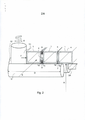
[0011] A invenção será agora descrita em maiores detalhes, fazendo-se referência aos desenhos anexos, nos quais: - a figura 1 mostra um esquema do princípio de fabricação de um tubo enrolado em forma de espiral, do tipo conhecido no segmento da técnica. - a figura 2 mostra o funcionamento de uma unidade de rolo, de acordo com a presente invenção; - a figura 3 mostra a construção de uma unidade de rolo, de acordo com outra modalidade da presente invenção; e - a figura 4 mostra uma vista global de um dispositivo de soldagem, de acordo com a presente invenção.[0011] The invention will now be described in greater detail, with reference to the attached drawings, in which: - Figure 1 shows a schematic of the manufacturing principle of a spiral-shaped tube, of the type known in the art. . - figure 2 shows the operation of a roller unit, according to the present invention; Figure 3 shows the construction of a roller unit, according to another embodiment of the present invention; and - figure 4 shows an overall view of a welding device according to the present invention.
[0012] Com referência ao dispositivo conhecido do estado da técnica e mostrado na figura 1, um tubo enrolado espiralado (4) é fabricado a partir de um perfil termoplástico (1), com uma seção transversal principalmente retangular. O perfil (1) é levado para um tambor de soldagem giratório (2), o qual apresenta um diâmetro correspondente ao diâmetro interno do tubo (4) a ser fabricado. O perfil (1) é enrolado mediante um movimento tipo espiral ou parafuso em torno do tambor de soldagem (2), conforme mostrado.[0012] With reference to the device known from the prior art and shown in figure 1, a spirally wound tube (4) is manufactured from a thermoplastic profile (1), with a mainly rectangular cross section. The profile (1) is taken to a rotating welding drum (2), which has a diameter corresponding to the inner diameter of the tube (4) to be manufactured. The profile (1) is wound by a spiral or screw-type movement around the welding drum (2) as shown.
[0013] Um cabeçote de soldagem (3) é colocado no espaçamento tipo cunha ou área de soldagem, formado entre duas voltas do perfil (1), uma volta entrando no tambor de soldagem, e a outra enrolada em torno de uma primeira volta do tambor de soldagem (2). O cabeçote de soldagem (3) é conectado a uma extrusora (não mostrado), produzindo uma massa de soldagem (6). A massa de soldagem (6) forma uma costura de solda externa (5) e/ou uma costura de solda interna (7) (ver a figura 2). A alimentação e propriedades da massa de soldagem (6), naturalmente, é regulada com a extrusora.[0013] A welding head (3) is placed in the wedge-type spacing or welding area, formed between two turns of the profile (1), one turn entering the welding drum, and the other wound around a first turn of the welding drum (2). The welding head (3) is connected to an extruder (not shown), producing a welding mass (6). The welding mass (6) forms an outer weld seam (5) and/or an inner weld seam (7) (see figure 2). The feed and properties of the solder paste (6), of course, are regulated with the extruder.
[0014] As porções de arestas opostas (1a, 1b) do perfil (1), portadoras de cordões extrudados da massa de soldagem (6), são comprimidas por meio de um ou mais rolos (10). Os eixos dos rolos (10) são radialmente orientados em relação ao tambor de soldagem (2) e tubo (4). A força correta que o rolo (10) deve aplicar no perfil (1) é dependente da força de tensão do perfil e do atrito entre o perfil (1) e o tambor de soldagem (2). Ao controlar a temperatura do perfil (1), o perfil enrolado irá se encolher um pouco, o que irá resultar em um maior ou menor atrito contra o tambor (2), e uma maior ou menor força de tensão no próprio perfil (1). Os rolos (10) funcionam como um dispositivo de costura, mediante compressão das arestas do perfil (1a) e (1b) de forma gradual, relativamente entre si, até que sejam costuradas juntas para completar a operação de soldagem. O tubo (4) é depois impulsionado para frente e para direita, para a seguinte etapa de fabricação ou transporte.[0014] The opposite edge portions (1a, 1b) of the profile (1), bearing extruded strands of the welding mass (6), are compressed by means of one or more rollers (10). The axes of the rollers (10) are radially oriented with respect to the welding drum (2) and tube (4). The correct force that the roller (10) must apply on the profile (1) is dependent on the tension force of the profile and the friction between the profile (1) and the welding drum (2). By controlling the temperature of the profile (1), the rolled profile will shrink a little, which will result in greater or lesser friction against the drum (2), and greater or lesser tension force on the profile itself (1) . The rollers (10) function as a sewing device, by compressing the edges of the profile (1a) and (1b) gradually, relatively to each other, until they are sewn together to complete the welding operation. The tube (4) is then pushed forward and to the right for the next manufacturing or transport step.
[0015] A figura 2 mostra o dispositivo básico de enrolamento e soldagem, de acordo com uma modalidade da invenção. No presente caso, o tambor (2) mostrado na figura 1 foi substituído por uma pluralidade de rolos e barras de deslizamento, cuja operação será explicada mais adiante. Em vez do tambor sólido (2) mostrado na figura 1, existe agora um dispositivo de enrolamento tendo uma estrutura relativamente aberta de barras de deslizamento (12) e (13), que oferece diversas vantagens. Uma dessas vantagens é que as etapas de direcionamento, aquecimento e alisamento do perfil e da costura de solda são agora muito mais fáceis, também, a partir do interior do perfil. Após a soldagem, o tubo (4) é deslizado sobre um tambor rotativo (2A) para a seguinte etapa de fabricação ou transporte. As barras de deslizamento (12, 13) são dispostas numa direção axial do tubo e definem através da extensão (D) e raio (R) uma superfície cilíndrica, a qual apresenta um diâmetro geralmente correspondente ao diâmetro interno do tubo a ser fabricado. O perfil termoplástico (1) tendo uma seção transversal substancialmente retangular é enrolado nas barras de deslizamento (12, 13) e dirigido ao longo do percurso em espiral (S) (ver também a figura 3) das barras (12, 13) para uma volta anterior do perfil, por meio dos rolos (10). Os rolos (1) podem ser ajustados (seta (d)) e espaçados ao longo do percurso em espiral, de modo que a posição de todos os rolos (10) assim ajustada define o desejado percurso em espiral (S).[0015] Figure 2 shows the basic winding and welding device, according to an embodiment of the invention. In the present case, the drum (2) shown in figure 1 has been replaced by a plurality of rollers and slide bars, the operation of which will be explained later. Instead of the solid drum (2) shown in Figure 1, there is now a winding device having a relatively open structure of slide bars (12) and (13), which offers several advantages. One of these advantages is that the steps of directing, heating and smoothing the profile and weld seam are now much easier, too, from the inside of the profile. After welding, the tube (4) is slid onto a rotating drum (2A) for the next manufacturing or transport step. The slide bars (12, 13) are arranged in an axial direction of the tube and define through the extension (D) and radius (R) a cylindrical surface, which has a diameter generally corresponding to the inner diameter of the tube to be manufactured. The thermoplastic profile (1) having a substantially rectangular cross section is wound on the slide bars (12, 13) and directed along the spiral path (S) (see also figure 3) of the bars (12, 13) to a previous turn of the profile, by means of rollers (10). The rollers (1) can be adjusted (arrow (d)) and spaced along the spiral path, so that the position of all the rollers (10) thus adjusted defines the desired spiral path (S).
[0016] No espaçamento “a” à esquerda e entre o perfil (1), são mostrados os cordões de massa de soldagem (8) e (9), aplicados por uma extrusora (não mostrado), ao longo, preferivelmente, das porções preaquecidas de aresta superior e inferior de duas superfícies do perfil (1a) e (1b). A exata posição na operação de enrolamento onde os cordões de solda (8) e (9) são aplicados, não constitui um fator crítico com relação à presente invenção, na medida em que o espaçamento “a” é largo o suficiente para receber os cordões. Isso pode ser feito em qualquer local, ao longo do percurso formado pelas barras de deslizamento (12) e (13) ou mesmo, antes de o perfil entrar em contato com as barras. Na seguinte volta do perfil para a direita, o espaçamento é fechado, e as costuras de solda superior e inferior (5) e (7) são formadas. Os cordões de massa de soldagem, dentro do escopo da invenção, podem ser aplicados em qualquer desejada configuração, por exemplo, somente um cordão em cada perfil (um cordão (8) e um cordão (9)), ou apenas um cordão, por exemplo, entre os cordões mostrados (8) ou (9) no perfil (1).[0016] In the spacing "a" to the left and between the profile (1), the weld putty beads (8) and (9) are shown, applied by an extruder (not shown), along, preferably, the portions top and bottom edge of two profile surfaces (1a) and (1b). The exact position in the winding operation where the weld beads (8) and (9) are applied does not constitute a critical factor with respect to the present invention, as the spacing "a" is wide enough to receive the beads . This can be done anywhere along the path formed by the slide bars (12) and (13) or even before the profile comes into contact with the bars. On the next turn of the profile to the right, the spacing is closed, and the top and bottom weld seams (5) and (7) are formed. Welding putty beads, within the scope of the invention, can be applied in any desired configuration, for example, only one bead in each profile (one bead (8) and one bead (9)), or just one bead per example, between the strands shown (8) or (9) on the profile (1).
[0017] A força (F) aplicada pelo rolo (10) no perfil, de acordo com a presente invenção, é controlada mediante ajuste da distância (d) do rolo (10), a partir do perfil (1), conforme mostrado na figura. Finalmente, as costuras de solda (5) e/ou (7) podem, logo após a soldagem, serem alisadas por meio de uma sapata deslizante (não mostrado) ou elemento similar, que se localizam contra as superfícies das costuras soldadas. Nessa modalidade da invenção, as barras de deslizamento (12) e (13) são estacionárias, enquanto um tambor rotativo (2A) puxa o perfil soldado das barras e transporta o tubo (4) para a etapa de fabricação seguinte. O tambor rotativo (2A) que suporta e avança o tubo (4) pode ser de qualquer tipo de construção mecânica. Também, as barras de deslizamento (12) e (13) podem girar em torno de seus eixos longitudinais.[0017] The force (F) applied by the roller (10) on the profile, according to the present invention, is controlled by adjusting the distance (d) of the roller (10), from the profile (1), as shown in figure. Finally, the weld seams (5) and/or (7) can, right after welding, be smoothed by means of a sliding shoe (not shown) or similar element, which are located against the surfaces of the welded seams. In this embodiment of the invention, the slide bars (12) and (13) are stationary, while a rotating drum (2A) pulls the welded profile of the bars and transports the tube (4) to the next manufacturing step. The rotating drum (2A) that supports and advances the tube (4) can be of any type of mechanical construction. Also, the slide bars (12) and (13) can rotate around their longitudinal axes.
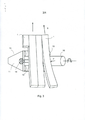
[0018] Retornando agora para a figura 3, é mostrada uma modalidade da presente invenção em que o rolo (10) foi construído integralizado, como uma unidade, geralmente indicado pela referência numérica (15). Na dita unidade, o rolo (10) dirige o perfil (1) ao longo de um percurso inclinado em forma de espiral (S), durante seu primeiro giro do dispositivo de soldagem. Fixados a um elemento de suporte (11) são dispostas as barras de deslizamento (12) e (13), e uma haste de ajuste (14) para o rolo (10). Ao girar a haste de ajuste (14) em cada direção mostrada pelas setas, o rolo (10) é desviado para estreitar ou alargar o espaçamento entre as duas mais recentes voltas do perfil (1) (espaçamento “a”, conforme visto na figura 2), com a intenção de manter a força (F), conforme aplicada no perfil (1), constante em cada rolo (10). O ajuste inicial é baseado em se ter igual deslocamento axial entre cada unidade (15) e seu rolo (10), a fim de tornar o percurso para o perfil que entra no dispositivo de soldagem o mais liso possível. A distância (Lr) para cada rolo “r”, contada a partir do primeiro rolo, onde começa a operação de enrolamento do perfil (1), é: Lr = nr x S/N, onde (n) é o número de ordem do rolo, (S) é a largura (mm) do perfil (1), e (N) é o número total de rolos (10). No exemplo mostrado na figura 4, N = 16.[0018] Returning now to Figure 3, an embodiment of the present invention is shown in which the roller (10) has been built integrally, as a unit, generally indicated by the numerical reference (15). In said unit, the roller (10) directs the profile (1) along an inclined path in the form of a spiral (S), during its first rotation of the welding device. Fixed to a support element (11) are arranged the slide bars (12) and (13), and an adjustment rod (14) for the roller (10). By turning the adjustment rod (14) in each direction shown by the arrows, the roller (10) is deflected to narrow or widen the spacing between the two most recent turns of the profile (1) (spacing "a", as seen in the figure 2), with the intention of maintaining the force (F), as applied to the profile (1), constant in each roller (10). The initial adjustment is based on having equal axial displacement between each unit (15) and its roller (10), in order to make the path for the profile entering the welding device as smooth as possible. The distance (Lr) for each roll "r", counted from the first roll, where the profile winding operation (1) begins, is: Lr = nr x S/N, where (n) is the order number of the roll, (S) is the width (mm) of the profile (1), and (N) is the total number of rolls (10). In the example shown in Figure 4, N = 16.
[0019] Deve ser observado que mesmo que os perfis (1) já soldados, mostrados na figura 3, pareçam se dispor de modo perpendicular às barras de deslizamento (12) e (13), existe, logicamente, sempre uma inclinação, como aquela do tipo mostrado na figura 1.[0019] It should be noted that even if the profiles (1) already welded, shown in Figure 3, appear to be arranged perpendicular to the slide bars (12) and (13), there is, of course, always an inclination, like that of the type shown in figure 1.
[0020] Durante a operação de soldagem, um sensor de força (ver a figura 4) em uma extremidade da haste de ajuste (14) detecta a força (F) aplicada em cada rolo (10). Quaisquer desvios de um valor desejado são então detectados, e qualquer ajuste da posição/das posições do rolo pode ser feito manualmente em cada unidade de rolo, baseado em um valor de força individual exibido, central e/ou automaticamente no painel de controle do dispositivo de soldagem (não mostrado).[0020] During the welding operation, a force sensor (see figure 4) at one end of the adjustment rod (14) senses the force (F) applied to each roller (10). Any deviations from a desired value are then detected, and any adjustment of roll position/positions can be made manually on each roll unit, based on an individual force value displayed centrally and/or automatically on the device's control panel of welding (not shown).
[0021] As unidades de rolo (15), de acordo com a invenção, são dispostas perifericamente ao longo do perímetro do tubo a ser fabricado. No exemplo da figura 4, dezesseis unidades são dispostas de modo circular, em iguais espaços nas extensões radiais (17), em um modelo tipo estrela. Conforme pode ser observado, cada unidade (15) apresenta um rolo (10), cuja posição pode ser ajustada ao longo da seta (d) (ver, também, a figura 2).[0021] The roller units (15), according to the invention, are arranged peripherally along the perimeter of the tube to be manufactured. In the example in Figure 4, sixteen units are arranged in a circular fashion, with equal spaces on the radial extensions (17), in a star-type model. As can be seen, each unit (15) has a roller (10), the position of which can be adjusted along the arrow (d) (see also figure 2).
[0022] O suporte (11) apresenta pontos de apoio para as barras de deslizamento (12, 13) e haste de ajuste (14). Além disso, a posição do sensor de força (16) é assinalada. Também, são mostrados a extensão (D) e o raio (R) das barras de deslizamento (12) e (13). Esses elementos definem, conforme discutido em conexão com a figura 2, a superfície de formato cilíndrico sobre a qual o tubo pode ser fabricado.[0022] The support (11) has support points for the slide bars (12, 13) and adjustment rod (14). In addition, the position of the force sensor (16) is signaled. Also, the extension (D) and radius (R) of the slide bars (12) and (13) are shown. These elements define, as discussed in connection with Figure 2, the cylindrical-shaped surface on which the tube can be fabricated.
[0023] Uma vantagem correlacionada ao método e dispositivo de soldagem de acordo com a invenção é o fato de que a soldagem é executada sobre uma estrutura rolante e não em um tambor ou cilindro fechado. Assim, existe espaço suficiente para acomodar o cabeçote da extrusora de massa de soldagem, diversos meios de aquecimento para aquecer as partes de perfil a serem soldadas, para uso também de meios interiores ao tubo para alisamento de costura de solda, e para a própria estrutura rolante em si. Os meios de aquecimento podem incluir sopradores de ar quente e aquecedores à base de infravermelho, do tipo LEISTER e INFRA, respectivamente, os meios de alisamento de costura de solda podem incluir sapatas de pressão ajustáveis feitas de PTFE ou materiais plásticos similares, apresentando um baixo coeficiente de atrito, por exemplo, ver o documento de patente EP 1.237.708. Esses dispositivos auxiliares são bem conhecidos na indústria e um especialista versado na técnica pode facilmente aplicar e usar os mesmos para alcançar satisfatórios resultados de soldagem.[0023] An advantage related to the welding method and device according to the invention is the fact that the welding is performed on a rolling structure and not on a drum or closed cylinder. Thus, there is enough space to accommodate the head of the welding putty extruder, various heating means to heat the profile parts to be welded, for use also of means inside the tube for smoothing the weld seam, and for the structure itself rolling itself. The heating means may include hot air blowers and infrared based heaters, of the LEISTER and INFRA type, respectively, the weld seam smoothing means may include adjustable pressure shoes made of PTFE or similar plastic materials, having a low coefficient of friction, for example, see EP 1,237,708. Such auxiliary devices are well known in the industry and a person skilled in the art can easily apply and use them to achieve satisfactory welding results.
[0024] Também, é evidente que o tubo soldado (4), de acordo com o escopo da presente invenção, pode ser transferido das unidades de rolo mostradas na figura 4 para um tambor tradicional rotativo, como o tambor (2) mostrado na figura 2, para posterior transporte, para operações de tratamento, corte e armazenamento, ou para uma construção similar à mostrada na figura 4, onde o tubo é girado e suportado por rolos ou elementos similares, ou para uma combinação de ambos. Também, conforme pode ser visto na figura 4, cada unidade de rolo (15) nas suas extensões radiais (17) pode ser deslizada ao longo de um eixo ou barra (18), a fim de alterar o diâmetro do tubo (4) a ser formado.[0024] Also, it is evident that the welded tube (4), in accordance with the scope of the present invention, can be transferred from the roller units shown in figure 4 to a traditional rotating drum, such as the drum (2) shown in figure 2, for further transport, for processing, cutting and storage operations, or for a construction similar to that shown in figure 4, where the tube is rotated and supported by rollers or similar elements, or for a combination of both. Also, as can be seen in Figure 4, each roller unit (15) on its radial extensions (17) can be slid along an axis or bar (18) in order to change the diameter of the tube (4) to be formed.
[0025] Deve ser entendido que as modalidades da invenção aqui divulgadas não são limitadas para estruturas específicas, etapas de processo, ou para os materiais aqui divulgados, podendo ser estendidas para equivalentes dos mesmos, conforme pode ser reconhecido por aqueles de habilidade nas técnicas relevantes; também, deve ser entendido que a terminologia empregada é aqui usada com a finalidade de apenas descrever particulares modalidades, não sendo pretendida de ser limitativa.[0025] It should be understood that the embodiments of the invention disclosed herein are not limited to specific structures, process steps, or materials disclosed herein, but may be extended to equivalents thereof, as may be recognized by those skilled in the relevant techniques ; also, it is to be understood that the terminology employed is used herein for the purpose of describing particular modalities only, and is not intended to be limiting.
[0026] A referência feita no presente relatório descritivo ao termo “uma modalidade” ou à expressão “a uma modalidade” significa que um específico aspecto, estrutura ou característica descrita em conexão com a modalidade é incluída em pelo menos uma modalidade da presente invenção. Desse modo, a inclusão de frases “em uma modalidade” ou “numa modalidade” em diversos locais do presente relatório não se refere necessariamente à mesma modalidade.[0026] Reference in this specification to the term "an embodiment" or the expression "to an embodiment" means that a specific aspect, structure or feature described in connection with the embodiment is included in at least one embodiment of the present invention. Thus, the inclusion of the phrases “in a modality” or “in a modality” in different places in this report does not necessarily refer to the same modality.
[0027] Conforme aqui usado, uma pluralidade de itens, elementos estruturais, elementos e/ou materiais componentes podem ser apresentados em uma lista comum de conveniência. Entretanto, essas listas devem ser preparadas, em que cada elemento da lista é individualmente identificado como um elemento único e separado. Portanto, nenhum elemento individual dessas listas deve ser considerado como de fato equivalente a qualquer outro elemento da mesma lista, apenas baseado na sua apresentação em um grupo comum, sem que haja indicações em contrário. Além disso, diversas modalidades e exemplos da presente invenção podem ser aqui referidos, juntamente com alternativas para os diversos componentes dos mesmos. Deve ser entendido que essas modalidades, exemplos e alternativas não devem ser consideradas como de fato equivalentes entre si, devendo ser consideradas como representações separadas e autônomas da presente invenção.[0027] As used herein, a plurality of items, structural elements, component elements and/or materials may be presented in a common list of convenience. However, these lists must be prepared, where each element of the list is individually identified as a single and separate element. Therefore, no individual element of these lists should be considered as in fact equivalent to any other element in the same list, just based on their presentation in a common group, without any indications to the contrary. Furthermore, various embodiments and examples of the present invention can be referred to herein, along with alternatives for the various components thereof. It should be understood that these modalities, examples and alternatives are not to be considered as in fact equivalent to each other and are to be considered as separate and autonomous representations of the present invention.
[0028] Além disso, os aspectos, estruturas ou características descritas podem ser combinadas de qualquer maneira adequada em uma ou mais modalidades. Numa eventual descrição, numerosos detalhes específicos são proporcionados, tais como, exemplos de comprimentos, larguras, formatos, etc., de modo a proporcionar um entendimento completo das modalidades da invenção. Entretanto, um especialista versado na técnica irá reconhecer que a invenção pode ser praticada sem a necessidade de um ou mais detalhes específicos, ou com outros métodos, componentes, materiais, etc. Em outros exemplos, estruturas, materiais ou operações bem conhecidas não são mostrados ou descritos em detalhes, para evitar aspectos que possam confundir a invenção.[0028] In addition, the features, structures or features described may be combined in any suitable way in one or more modalities. In an eventual description, numerous specific details are provided, such as examples of lengths, widths, formats, etc., in order to provide a complete understanding of the embodiments of the invention. However, one skilled in the art will recognize that the invention can be practiced without the need for one or more specific details, or with other methods, components, materials, etc. In other examples, well-known structures, materials or operations are not shown or described in detail, to avoid aspects that might confuse the invention.
[0029] Conquanto que os exemplos anteriores sejam ilustrativos dos princípios da presente invenção, em uma ou mais particulares aplicações, será evidente para os especialistas versados na técnica que numerosas modificações de forma, utilização e detalhes da implementação poderão ser feitas sem o exercício de faculdade inventiva, e sem que sejam afastados dos princípios e conceitos da presente invenção. Consequentemente, a invenção não é pretendida de ser limitada, exceto com relação ao conjunto de reivindicações estabelecido em anexo.[0029] While the foregoing examples are illustrative of the principles of the present invention, in one or more particular applications, it will be apparent to those skilled in the art that numerous modifications of form, use, and implementation details may be made without exercising faculty. inventive, and without departing from the principles and concepts of the present invention. Accordingly, the invention is not intended to be limited, except with respect to the set of claims set out in the appendix.
Claims (5)
Applications Claiming Priority (3)
| Application Number | Priority Date | Filing Date | Title |
|---|---|---|---|
| FI20126219A FI124400B (en) | 2012-11-20 | 2012-11-20 | Method and apparatus in the manufacture of a helically wound and welded tube |
| FI20126219 | 2012-11-20 | ||
| PCT/FI2013/051082 WO2014080076A1 (en) | 2012-11-20 | 2013-11-19 | A method and apparatus in the manufacture of a spirally wound and welded tube |
Publications (2)
| Publication Number | Publication Date |
|---|---|
| BR112015011453A2 BR112015011453A2 (en) | 2017-07-11 |
| BR112015011453B1 true BR112015011453B1 (en) | 2021-05-04 |
Family
ID=50775594
Family Applications (1)
| Application Number | Title | Priority Date | Filing Date |
|---|---|---|---|
| BR112015011453-9A BR112015011453B1 (en) | 2012-11-20 | 2013-11-19 | method and device for manufacturing a spirally wound and welded tube |
Country Status (15)
| Country | Link |
|---|---|
| US (1) | US9821514B2 (en) |
| EP (1) | EP2922683B1 (en) |
| JP (1) | JP6363614B2 (en) |
| BR (1) | BR112015011453B1 (en) |
| CA (1) | CA2891689C (en) |
| CL (1) | CL2015001326A1 (en) |
| DK (1) | DK2922683T3 (en) |
| EA (1) | EA028753B1 (en) |
| FI (1) | FI124400B (en) |
| LT (1) | LT2922683T (en) |
| MX (1) | MX2015006297A (en) |
| MY (1) | MY176611A (en) |
| PL (1) | PL2922683T3 (en) |
| SA (1) | SA515360449B1 (en) |
| WO (1) | WO2014080076A1 (en) |
Families Citing this family (1)
| Publication number | Priority date | Publication date | Assignee | Title |
|---|---|---|---|---|
| CN108016026B (en) * | 2017-12-20 | 2020-10-16 | 江西金阳管业有限公司 | Forming method of HDPE double-wall winding pipe |
Family Cites Families (12)
| Publication number | Priority date | Publication date | Assignee | Title |
|---|---|---|---|---|
| JPS4636555Y1 (en) * | 1970-04-02 | 1971-12-15 | ||
| US3914151A (en) | 1971-11-02 | 1975-10-21 | Owens Corning Fiberglass Corp | Mandrel for the production of reinforced plastic tubing |
| BE790832A (en) | 1971-11-02 | 1973-04-30 | Owens Corning Fiberglass Corp | TUBE MAKING CHUCK |
| DE2308418B2 (en) * | 1972-06-21 | 1976-04-08 | Petzetakis, Aristovoulos George, Moschaton, Piräus (Griechenland) | METHOD AND DEVICE FOR MANUFACTURING AN IN PARTICULAR LARGE-CALIBRATED TUBE FROM THERMOPLASTIC PLASTIC |
| US4033808A (en) | 1972-06-21 | 1977-07-05 | Aristovoulos George Petzetakis | Apparatus for the production of hollow bodies, especially large-diameter ducts from thermoplastic synthetic resin |
| JPH0692132B2 (en) * | 1987-07-17 | 1994-11-16 | 大日本プラスチックス株式会社 | Plastic spiral wound double tube and its manufacturing method |
| DE3931614A1 (en) * | 1989-09-22 | 1991-04-11 | Petzetakis George A | METHOD FOR PRODUCING A LARGE-CALIBRATED PLASTIC PIPE AND EXTRACTION TOOL FOR IMPLEMENTING THE METHOD |
| FI95219C (en) * | 1992-04-30 | 1996-01-10 | Kwh Pipe Ab Oy | Welding process in the manufacture of spiral wound tube and welding head for carrying out the process |
| US6306235B1 (en) * | 1997-10-16 | 2001-10-23 | Nomaco, Inc. | Spiral formed products and method of manufacture |
| AUPP610698A0 (en) * | 1998-09-22 | 1998-10-15 | Rib Loc Australia Pty. Ltd. | Method and apparatus for direct lining of conduits |
| US6105649A (en) * | 1998-09-30 | 2000-08-22 | Jerry C. Levingston | Pipe extrusion apparatus including winding a hollow profile |
| FI107522B (en) * | 1999-11-03 | 2001-08-31 | Kwh Pipe Ab Oy | Method and apparatus for producing spirally wound tubes |
-
2012
- 2012-11-20 FI FI20126219A patent/FI124400B/en active IP Right Grant
-
2013
- 2013-11-19 MX MX2015006297A patent/MX2015006297A/en active IP Right Grant
- 2013-11-19 CA CA2891689A patent/CA2891689C/en active Active
- 2013-11-19 EP EP13857213.6A patent/EP2922683B1/en active Active
- 2013-11-19 DK DK13857213.6T patent/DK2922683T3/en active
- 2013-11-19 WO PCT/FI2013/051082 patent/WO2014080076A1/en active Application Filing
- 2013-11-19 LT LTEP13857213.6T patent/LT2922683T/en unknown
- 2013-11-19 BR BR112015011453-9A patent/BR112015011453B1/en active IP Right Grant
- 2013-11-19 PL PL13857213T patent/PL2922683T3/en unknown
- 2013-11-19 EA EA201590603A patent/EA028753B1/en not_active IP Right Cessation
- 2013-11-19 JP JP2015543489A patent/JP6363614B2/en active Active
- 2013-11-19 MY MYPI2015701379A patent/MY176611A/en unknown
- 2013-11-19 US US14/440,256 patent/US9821514B2/en active Active
-
2015
- 2015-05-15 CL CL2015001326A patent/CL2015001326A1/en unknown
- 2015-05-18 SA SA515360449A patent/SA515360449B1/en unknown
Also Published As
| Publication number | Publication date |
|---|---|
| US9821514B2 (en) | 2017-11-21 |
| CL2015001326A1 (en) | 2016-06-10 |
| MY176611A (en) | 2020-08-18 |
| WO2014080076A1 (en) | 2014-05-30 |
| JP6363614B2 (en) | 2018-07-25 |
| US20150314525A1 (en) | 2015-11-05 |
| MX2015006297A (en) | 2015-12-09 |
| JP2015535497A (en) | 2015-12-14 |
| EA201590603A1 (en) | 2015-11-30 |
| CA2891689C (en) | 2021-01-26 |
| EA028753B1 (en) | 2017-12-29 |
| EP2922683A1 (en) | 2015-09-30 |
| DK2922683T3 (en) | 2020-03-23 |
| SA515360449B1 (en) | 2018-03-11 |
| PL2922683T3 (en) | 2020-06-29 |
| EP2922683B1 (en) | 2020-01-01 |
| FI124400B (en) | 2014-08-15 |
| CA2891689A1 (en) | 2014-05-30 |
| BR112015011453A2 (en) | 2017-07-11 |
| LT2922683T (en) | 2020-04-10 |
| EP2922683A4 (en) | 2016-08-24 |
| FI20126219A (en) | 2014-05-21 |
Similar Documents
| Publication | Publication Date | Title |
|---|---|---|
| BR0015472B1 (en) | process and apparatus for making spiral wound tubes. | |
| CA2685020C (en) | Conduits and method of forming | |
| ES2243010T3 (en) | PRODUCTS IN SPIRAL FORM AND MANUFACTURING PROCEDURE. | |
| BRPI0621126B1 (en) | Apparatus for manufacturing a tube-shaped helical-wound structure, a tubular structure and a method of manufacturing a tubular structure | |
| US3173822A (en) | Apparatus for continuously forming thermoplastic flexible tubing | |
| BR112015011453B1 (en) | method and device for manufacturing a spirally wound and welded tube | |
| BR112015011452B1 (en) | METHOD AND DEVICE FOR SPIRAL WINDING OF A THERMOPLASTIC PROFILE IN THE MANUFACTURING OF WELDED PLASTIC PIPES | |
| BR112020001131B1 (en) | TAPE APPLICATION DEVICE FOR HELICAL APPLICATION OF A TAPE FROM A ROLL | |
| US3089535A (en) | Apparatus for making a wire reinforced flexible hose | |
| JP2015535497A5 (en) | ||
| BRPI1106474B1 (en) | equipment for the production of helical plastic tubes with oval and adjustable winding head | |
| JPS61167534A (en) | Continuous manufacture of heat-shrinkable tube | |
| TH25119B (en) | Methods of making tubing that are coiled |
Legal Events
| Date | Code | Title | Description |
|---|---|---|---|
| B06F | Objections, documents and/or translations needed after an examination request according [chapter 6.6 patent gazette] | ||
| B06F | Objections, documents and/or translations needed after an examination request according [chapter 6.6 patent gazette] | ||
| B06I | Publication of requirement cancelled [chapter 6.9 patent gazette] |
Free format text: ANULADA A PUBLICACAO CODIGO 6.6.1 NA RPI NO 2462 DE 13/03/2018 POR TER SIDO INDEVIDA. |
|
| B06U | Preliminary requirement: requests with searches performed by other patent offices: procedure suspended [chapter 6.21 patent gazette] | ||
| B09A | Decision: intention to grant [chapter 9.1 patent gazette] | ||
| B16A | Patent or certificate of addition of invention granted [chapter 16.1 patent gazette] |
Free format text: PRAZO DE VALIDADE: 20 (VINTE) ANOS CONTADOS A PARTIR DE 19/11/2013, OBSERVADAS AS CONDICOES LEGAIS. |