BR112015007998B1 - self-ligating orthodontic bracket - Google Patents
self-ligating orthodontic bracket Download PDFInfo
- Publication number
- BR112015007998B1 BR112015007998B1 BR112015007998-9A BR112015007998A BR112015007998B1 BR 112015007998 B1 BR112015007998 B1 BR 112015007998B1 BR 112015007998 A BR112015007998 A BR 112015007998A BR 112015007998 B1 BR112015007998 B1 BR 112015007998B1
- Authority
- BR
- Brazil
- Prior art keywords
- lingual
- clamp
- gingival
- locking
- fins
- Prior art date
Links
Images


Classifications
-
- A—HUMAN NECESSITIES
- A61—MEDICAL OR VETERINARY SCIENCE; HYGIENE
- A61C—DENTISTRY; APPARATUS OR METHODS FOR ORAL OR DENTAL HYGIENE
- A61C7/00—Orthodontics, i.e. obtaining or maintaining the desired position of teeth, e.g. by straightening, evening, regulating, separating, or by correcting malocclusions
- A61C7/12—Brackets; Arch wires; Combinations thereof; Accessories therefor
- A61C7/28—Securing arch wire to bracket
- A61C7/34—Securing arch wire to bracket using lock pins
-
- A—HUMAN NECESSITIES
- A61—MEDICAL OR VETERINARY SCIENCE; HYGIENE
- A61C—DENTISTRY; APPARATUS OR METHODS FOR ORAL OR DENTAL HYGIENE
- A61C7/00—Orthodontics, i.e. obtaining or maintaining the desired position of teeth, e.g. by straightening, evening, regulating, separating, or by correcting malocclusions
- A61C7/12—Brackets; Arch wires; Combinations thereof; Accessories therefor
- A61C7/14—Brackets; Fixing brackets to teeth
-
- A—HUMAN NECESSITIES
- A61—MEDICAL OR VETERINARY SCIENCE; HYGIENE
- A61C—DENTISTRY; APPARATUS OR METHODS FOR ORAL OR DENTAL HYGIENE
- A61C7/00—Orthodontics, i.e. obtaining or maintaining the desired position of teeth, e.g. by straightening, evening, regulating, separating, or by correcting malocclusions
- A61C7/12—Brackets; Arch wires; Combinations thereof; Accessories therefor
- A61C7/125—Mouth tissue protecting means, e.g. bracket caps
-
- A—HUMAN NECESSITIES
- A61—MEDICAL OR VETERINARY SCIENCE; HYGIENE
- A61C—DENTISTRY; APPARATUS OR METHODS FOR ORAL OR DENTAL HYGIENE
- A61C7/00—Orthodontics, i.e. obtaining or maintaining the desired position of teeth, e.g. by straightening, evening, regulating, separating, or by correcting malocclusions
- A61C7/12—Brackets; Arch wires; Combinations thereof; Accessories therefor
- A61C7/20—Arch wires
-
- A—HUMAN NECESSITIES
- A61—MEDICAL OR VETERINARY SCIENCE; HYGIENE
- A61C—DENTISTRY; APPARATUS OR METHODS FOR ORAL OR DENTAL HYGIENE
- A61C7/00—Orthodontics, i.e. obtaining or maintaining the desired position of teeth, e.g. by straightening, evening, regulating, separating, or by correcting malocclusions
- A61C7/12—Brackets; Arch wires; Combinations thereof; Accessories therefor
- A61C7/28—Securing arch wire to bracket
- A61C7/285—Locking by rotation
-
- A—HUMAN NECESSITIES
- A61—MEDICAL OR VETERINARY SCIENCE; HYGIENE
- A61C—DENTISTRY; APPARATUS OR METHODS FOR ORAL OR DENTAL HYGIENE
- A61C7/00—Orthodontics, i.e. obtaining or maintaining the desired position of teeth, e.g. by straightening, evening, regulating, separating, or by correcting malocclusions
- A61C7/12—Brackets; Arch wires; Combinations thereof; Accessories therefor
- A61C7/28—Securing arch wire to bracket
- A61C7/287—Sliding locks
-
- A—HUMAN NECESSITIES
- A61—MEDICAL OR VETERINARY SCIENCE; HYGIENE
- A61C—DENTISTRY; APPARATUS OR METHODS FOR ORAL OR DENTAL HYGIENE
- A61C7/00—Orthodontics, i.e. obtaining or maintaining the desired position of teeth, e.g. by straightening, evening, regulating, separating, or by correcting malocclusions
- A61C7/12—Brackets; Arch wires; Combinations thereof; Accessories therefor
- A61C7/28—Securing arch wire to bracket
- A61C7/30—Securing arch wire to bracket by resilient means; Dispensers therefor
Landscapes
- Health & Medical Sciences (AREA)
- Oral & Maxillofacial Surgery (AREA)
- Dentistry (AREA)
- Epidemiology (AREA)
- Life Sciences & Earth Sciences (AREA)
- Animal Behavior & Ethology (AREA)
- General Health & Medical Sciences (AREA)
- Public Health (AREA)
- Veterinary Medicine (AREA)
- Engineering & Computer Science (AREA)
- Biomedical Technology (AREA)
- Dental Tools And Instruments Or Auxiliary Dental Instruments (AREA)
Abstract
“BRAQUETE ORTODÔNTICO AUTOLIGÁVEL” A presente invenção emprega um braquete ortodôntico autoligante compreendendo um corpo tendo um par de aletas de amarrilho gengivais espaçadas lateralmente e um par de aletas de amarrilho oclusais espaçadas lateralmente, as aletas de amarrilho gengivais e oclusais se projetando a partir de uma superfície labial do corpo: uma fenda do fio ortodôntico se estendendo de forma mesial-distal por todo o corpo e entre as aletas de amarrilho gengivais e oclusais para acomodar um fio ortodôntico: um grampo de pivotamento, de travamento controlado, e de deslizamento livre em que o grampo permite alocação e remoção do fio ortodôntico quando está na posição aberta e previne o deslocamento do fio ortodôntico do membro de braquete quando está na posição fechada.“SELF-LIGATING ORTHODONTIC BRACKET” The present invention employs a self-ligating orthodontic bracket comprising a body having a pair of laterally spaced gingival fin fins and a pair of laterally spaced occlusal tether fins, the gingival and occlusal tether fins protruding from a labial surface of the body: a gap in the orthodontic wire extending mesially-distally across the body and between the gingival and occlusal ligament fins to accommodate an orthodontic wire: a pivoting clamp, controlled locking, and free sliding in that the clamp allows allocation and removal of the orthodontic wire when it is in the open position and prevents the displacement of the orthodontic wire from the bracket member when it is in the closed position.
Description
[001] Este pedido de patente reivindica benefício do e prioridade ao Pedido de Patente Provisório U.S. Ser. No. 61/711.381, depositado em 9 de outubro de 2012 e ao Pedido de Patente Provisório U.S. Ser. No. 61/768.317, depositado em 22 de fevereiro de 2013, que são aqui incorporados por referência para todos os propósitos.[001] This patent application claims benefit of and priority to US Ser. Provisional Patent Application No. 61 / 711,381, filed on October 9, 2012 and US Ser. Provisional Patent Application No. 61 / 768,317, filed on February 22, 2013, which are incorporated herein by reference for all purposes.
[002] A presente invenção é direcionada ao campo dos ortodônticos, e especificamente ao campo das armações de braquete ortodôntico.[002] The present invention is directed to the field of orthodontics, and specifically to the field of orthodontic bracket frames.
[003] A presente invenção fornece braquetes ortodônticos autoligados aperfeiçoados. Em um aspecto, a presente invenção fornece um braquete ortodôntico autoligado compreendendo: um corpo tendo um par de aletas de amarrilho gengivais espaçadas lateralmente e um par de aletas de amarrilho oclusais espaçadas lateralmente, as aletas de amarrilho oclusais e gengivais se projetando de uma superfície labial do corpo; uma fenda do fio ortodôntico que se estende de modo mesial-distal pelo corpo e entre as aletas de amarrilho oclusais e gengivais para acomodar um fio ortodôntico; um grampo de deslizamento livre, travamento controlado, ou pivotante, em que o grampo permite a colocação e remoção do fio ortodôntico quando na posição aberta e evita o deslocamento do fio ortodôntico do membro de braquete quando na posição fechada.[003] The present invention provides improved self-ligating orthodontic brackets. In one aspect, the present invention provides a self-ligating orthodontic bracket comprising: a body having a pair of laterally spaced gingival fins and a pair of laterally spaced occlusal ligation fins, the occlusal and gingival ligation fins protruding from a lip surface of the body; a slit in the orthodontic wire that extends mesially-distally across the body and between the occlusal and gingival banding fins to accommodate an orthodontic wire; a free-sliding, controlled locking, or pivoting clamp, in which the clamp allows the placement and removal of the orthodontic wire when in the open position and prevents displacement of the orthodontic wire from the bracket member when in the closed position.
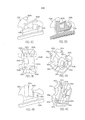
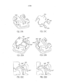
[004] As FIGS. 1A-1F são várias visões de uma primeira forma de realização da presente invenção.[004] FIGS. 1A-1F are various views of a first embodiment of the present invention.
[005] As FIGS. 2A-2C são várias visões de uma segunda forma de realização da presente invenção. realização da presente invenção.[005] FIGS. 2A-2C are various views of a second embodiment of the present invention. realization of the present invention.
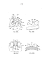
[007] As FIGS. 4A-4D são várias visões de uma quarta forma de realização da presente invenção.[007] FIGS. 4A-4D are various views of a fourth embodiment of the present invention.
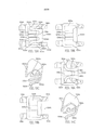
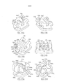
[008] As FIGS. 5A-5E são várias visões de uma quinta forma de realização da presente invenção.[008] FIGS. 5A-5E are various views of a fifth embodiment of the present invention.
[009] As FIGS. 6A-6D são várias visões de uma sexta forma de realização da presente invenção.[009] FIGS. 6A-6D are various views of a sixth embodiment of the present invention.
[0010] As FIGS. 7A-7C são várias visões de uma sétima forma de realização da presente invenção.[0010] FIGS. 7A-7C are various views of a seventh embodiment of the present invention.
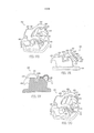
[0011] As FIGS. 8A-8E são várias visões de uma oitava forma de realização da presente invenção.[0011] FIGS. 8A-8E are various views of an eighth embodiment of the present invention.
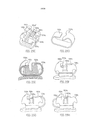
[0012] As FIGS. 9A-9H são várias visões de uma nona forma de realização da presente invenção.[0012] FIGS. 9A-9H are various views of a ninth embodiment of the present invention.
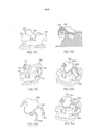
[0013] As FIGS. 10A-10D são várias visões de uma décima forma de realização da presente invenção.[0013] FIGS. 10A-10D are various views of a tenth embodiment of the present invention.
[0014] As FIGS. 11A-11C são várias visões de uma décima primeira forma de realização da presente invenção.[0014] FIGS. 11A-11C are various views of an eleventh embodiment of the present invention.
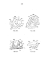
[0015] As FIGS. 12A-12C são várias visões de uma décima segunda forma de realização da presente invenção.[0015] FIGS. 12A-12C are various views of an twelfth embodiment of the present invention.
[0016] As FIGS. 13A-13C são várias visões de uma décima terceira forma de realização da presente invenção.[0016] FIGS. 13A-13C are various views of a thirteenth embodiment of the present invention.
[0017] As FIGS. 14A-14C são várias visões de uma décima quarta forma de realização da presente invenção.[0017] FIGS. 14A-14C are various views of a fourteenth embodiment of the present invention.
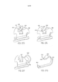
[0018] As FIGS. 15A-15C são várias visões de uma décima quinta forma de realização da presente invenção.[0018] FIGS. 15A-15C are various views of a fifteenth embodiment of the present invention.
[0019] As FIGS. 16A-16C são várias visões de uma décima sexta forma de realização da presente invenção.[0019] FIGS. 16A-16C are various views of a sixteenth embodiment of the present invention.
[0020] As FIGS. 17A-17N são várias visões de uma décima sétima forma de realização da presente invenção.[0020] FIGS. 17A-17N are various views of a seventeenth embodiment of the present invention.
[0021] As FIGS. 18A-18D são várias visões de uma décima oitava forma de realização da presente invenção.[0021] FIGS. 18A-18D are various views of an eighteenth embodiment of the present invention.
[0022] As FIGS. 19A-19F são várias visões de uma décima nona forma de realização da presente invenção.[0022] FIGS. 19A-19F are various views of a nineteenth embodiment of the present invention.
[0023] As FIGS. 20A-20B são várias visões de uma vigésima forma de realização da presente invenção.[0023] FIGS. 20A-20B are various views of a twentieth embodiment of the present invention.
[0024] As FIGS. 21A-21C são várias visões de uma vigésima primeira forma de realização da presente invenção.[0024] FIGS. 21A-21C are various views of an twenty-first embodiment of the present invention.
[0025] As FIGS. 22A-22B são várias visões de uma vigésima segunda forma de realização da presente invenção.[0025] FIGS. 22A-22B are various views of a twenty-second embodiment of the present invention.
[0026] As FIGS. 23A-23B são várias visões de uma vigésima terceira forma de realização da presente invenção.[0026] FIGS. 23A-23B are various views of a twenty-third embodiment of the present invention.
[0027] As FIGS. 24A-24C são várias visões de uma vigésima quarta forma de realização da presente invenção.[0027] FIGS. 24A-24C are various views of a twenty-fourth embodiment of the present invention.
[0028] As FIGS. 25A-25C são várias visões de uma vigésima quinta forma de realização da presente invenção.[0028] FIGS. 25A-25C are various views of a twenty-fifth embodiment of the present invention.
[0029] As FIGS. 26A-26C são várias visões de uma vigésima sexta forma de realização da presente invenção.[0029] FIGS. 26A-26C are various views of a twenty-sixth embodiment of the present invention.
[0030] As FIGS. 27A-27C são várias visões de uma vigésima sétima forma de realização da presente invenção.[0030] FIGS. 27A-27C are various views of a twenty-seventh embodiment of the present invention.
[0031] As FIGS. 28A-28C são várias visões de uma vigésima oitava forma de realização da presente invenção.[0031] FIGS. 28A-28C are various views of a twenty-eighth embodiment of the present invention.
[0032] As FIGS. 29A-29C são várias visões de uma vigésima nona forma de realização da presente invenção.[0032] FIGS. 29A-29C are various views of a twenty-ninth embodiment of the present invention.
[0033] As FIGS. 30A-30C são várias visões de uma trigésima forma de realização da presente invenção.[0033] FIGS. 30A-30C are various views of a thirtieth embodiment of the present invention.
[0034] As FIGS. 31A-31C são várias visões de uma trigésima primeira forma de realização da presente invenção.[0034] FIGS. 31A-31C are various views of an thirty-first embodiment of the present invention.
[0035] É apreciado que a presente invenção fornece várias formas de realização de uma montagem de braquete ortodôntico autoligado que inclui um braquete e grampo(s) de travamento. O braquete tem uma posição fechada em que o grampo inibe o acesso a uma fenda do fio ortodôntico e uma posição aberta em que o grampo permite acesso à ranhura do fio ortodôntico.[0035] It is appreciated that the present invention provides several embodiments of a self-ligating orthodontic bracket assembly that includes a bracket and locking clamp (s). The bracket has a closed position in which the clamp inhibits access to a crack in the orthodontic wire and an open position in which the clamp allows access to the groove in the orthodontic wire.
[0036] Em geral, o braquete ilustrado inclui um corpo e uma base. O corpo pode incluir a fenda do fio ortodôntico (duas áreas de recepção posicionadas mesial e distalmente do corpo do braquete), uma primeira aleta de amarrilho (por exemplo, aleta(s) de amarrilhos gengivais), uma segunda aleta de amarrilho (por exemplo, aleta(s) de amarrilhos oclusais), e uma região entre as aletas que se estende gengival-oclusalmente através do corpo e pode ser em geral, definida por pelo menos um dos espaçadores laterais ou uma porção de ponte das aletas de amarrilho gengivais e o espaçador lateral ou uma porção de ponte da aletas de amarrilho oclusais. A base conecta o braquete a um dente e pode incluir uma porção de fixação que define um padrão, que recebe um adesivo e é formado para afixar ao dente. Em uma forma de realização específica, o lado lingual da porção de fixação afixa ao lado labial do dente. Na formação, a base pode ser ligada ao corpo com soldas. Em outras formações, a base pode ser fixada de outras maneiras ou formada em uma parte única com o corpo.[0036] In general, the illustrated bracket includes a body and a base. The body may include the crack of the orthodontic wire (two receiving areas positioned mesially and distally from the bracket body), a first loop fin (for example, gingival loop fin (s)), a second loop fin (for example , occlusal strap fin (s), and a region between the fins that extends gingival-occlusally across the body and can generally be defined by at least one of the side spacers or a bridge portion of the gingival strap fins and the side spacer or a bridge portion of the occlusal strapping fins. The base connects the bracket to a tooth and may include a fixing portion that defines a pattern, which receives an adhesive and is formed to affix to the tooth. In a specific embodiment, the lingual side of the fixation portion attaches to the labial side of the tooth. In formation, the base can be connected to the body with welds. In other formations, the base can be fixed in other ways or formed in a single part with the body.
[0037] Se referindo agora às FIGS. 1A a 1F, um braquete ortodôntico autoligado é mostrado e é em geral indicado pelo número de referência 1010. A FIG. 1A é uma visão em perspectiva de um braquete dental autoligado em uma posição fechada de acordo com a presente invenção com um espaçamento lateral entre as aletas de amarrilho gengivais e uma porção labial (por exemplo, porção de gancho) que se estende das respectivas aletas de amarrilho gengivais mesial e distal para formar as áreas de recepção. As porções labiais que se estendem para fora dos lados mesial e distal do corpo para receber uma porção de aba (por exemplo, um forcado) do grampo. A extremidade livre labial do grampo (por exemplo, porção de ponta gengival) inclui as porções de aba do grampo, que podem ser deformados para se ajustar ao contorno da área de recepção abaixo das porções de gancho das aletas de amarrilho gengivais.[0037] Referring now to FIGS. 1A to 1F, a self-ligating orthodontic bracket is shown and is generally indicated by
[0038] Mais particularmente, o braquete ortodôntico 1000 inclui um corpo 1012 e uma base de suporte lingual 1014 ligada ao corpo. A base de montagem 1014 tem uma superfície lingual a ser fixada a um dente. Em geral, o corpo 1012 define um membro quadrado, retângulo ou de outro modo formado. Contudo, é apreciado que o corpo 1012 pode ser definido através de várias outras configurações formadas tais como uma forma de rombo, uma forma circular, uma forma oval, ou membro de outro modo formado.[0038] More particularly, the orthodontic bracket 1000 includes a
[0039] Um par de aletas de amarrilho gengivais espaçadas lateralmente 1016 e um par de aletas de amarrilho oclusais espaçadas lateralmente 1018 se estendem da superfície labial do corpo 1012. As aletas de amarrilho gengivais 1016 e as aletas de amarrilho oclusais 1018 em geral, curvam lingualmente. Uma região entre as aletas 1024 se estende gengival- oclusalmente através do corpo 1012 e pode ser em geral definida pelo espaçamento lateral das aletas de amarrilho gengivais 1016 e/ou o espaçamento lateral da aleta de amarrilho oclusal 1018. A região entre as aletas 1024 pode ser uma passagem aberta (por exemplo, não obstruída) ou pode ser uma passagem fechada (parcial ou completamente obstruída) FIGS. 1A-1 F, ou diferente. Uma fenda do fio ortodôntico 1020 se estende mesial- distalmente através do corpo 1012 e entre as aletas de amarrilho gengivais e oclusais as 1016 e 1018. A fenda do fio ortodôntico 1020 abre labialmente para receber um fio ortodôntico (não mostrado), A fenda do fio ortodôntico 1020 pode ser interrompida na região entre as aletas 24 do corpo.[0039] A pair of laterally spaced
[0040] O braquete 1010 também pode incluir um mecanismo de travamento que inclui um grampo de travamento 1026 para manter o fio ortodôntico na fenda do fio ortodôntico 1020 enquanto na posição fechada. Este grampo de travamento 1026 é estruturado em uma configuração transversal substancialmente na forma em U, e um lado deste é formado como uma extremidade livre lingual 1028 (uma porção localizada no lado da língua) localizada no lado de base e se estendendo ao longo da base (através de uma abertura formada entre o corpo 1012 e a base 1014), enquanto o outro lado deste é formado como uma extremidade livre labial 1030 tendo substancialmente a mesma largura que o comprimento da fenda do fio ortodôntico 1020 e se estendendo sobre o lado superior da ranhura. A extremidade livre lingual 1028 e a extremidade livre labial 1030 possam ser interconectadas por uma porção curvada 1032.[0040] The
[0041] O grampo de travamento 1026 pode ser formado de um membro elástico em que uma porção entalhada 1034 é substancialmente fornecida no centro de uma porção de extremidade de amarrilho da extremidade livre labial 1030 (uma porção localizada no lado labial). A porção de entalhe 1034 pode ser definida pelas porções de aba esquerda e direita (por exemplo, mesial e distal) 1031 da porção oposta à base 1028, que é a porção de topo em forma de T ou Y na configuração substancialmente em forma de T ou Y do grampo de travamento 1026.[0041] The
[0042] Além disso, visto que a porção entalhada 1034 do grampo de travamento pode ser correspondentemente fornecida para a largura do corpo do braquete (por exemplo, porções de extremidade mesial/distal livre/aberta) de modo a ser ajustada a este, o deslocamento e torcedura das porções de aba do grampo de travamento 1026 na direção longitudinal da ranhura podem ser eficazmente inibidos. A saber, com relação ao deslocamento e torcedura da porção de amarrilho do grampo de travamento 1026 na direção longitudinal do corpo, tal deslocamento pode ser inibido por uma área de recepção fornecida por intermédio de um lado mesial e/ou um lado distal do corpo de braquete 1012.[0042] In addition, since the notched portion 1034 of the locking clamp can be correspondingly provided for the width of the bracket body (for example, free / open mesial / distal end portions) so as to fit this, the displacement and twisting of the flap portions of the
[0043] A área de recepção pode ser definida por um membro de recepção 1036 que se estende da extremidade externa livre/aberta do corpo de braquete 1012. Preferivelmente, a extremidade externa livre/aberta do corpo de braquete é em geral coplanar com as extremidades livres mesial/distal da fenda do fio ortodôntico 1020, ainda que não necessário. Em um exemplo específico como mostrado nas FIGS 1A-1F, o membro de recepção 1036 pode incluir porções de gancho labiais 1038 que se estendem mesial/distalmente da extremidade externa livre/aberta da aleta de amarrilho gengival 1016 do corpo de braquete 1012. A porção de gancho labial pode ser fornecida para parar uma ponta do grampo de travamento 1026 (por exemplo, abas 1031) em uma posição de gancho em uma porção de extremidade livre/aberta do corpo de braquete. Mais particularmente, uma porção de gancho labial mesial 1039 pode se estender mesialmente da porção de extremidade livre/aberta mesial do corpo de braquete (por exemplo, que se estende mesialmente da aleta de amarrilho gengival mesial) e uma porção de gancho labial distal 1038b pode se estender distalmente de uma porção de extremidade livre/aberta distal do corpo de braquete (por exemplo, que se estende distalmente das aletas de amarrilho gengivais distais). Desejavelmente, as porções de gancho labiais 1039 e 1038b previnem que o fio ortodôntico seja involuntariamente removido da fenda do fio ortodôntico 1020 limitando o movimento labial do grampo de travamento 1026 enquanto na posição fechada.[0043] The receiving area can be defined by a receiving
[0044] O grampo de travamento 1026 também pode incluir uma porção de extremidade de engate 1040, que pode ser formada por uma porção entalhada, uma porção rebaixada, uma projeção, ou outros. A porção de extremidade de engate pode ser formada em uma porção de extremidade traseira da extremidade livre lingual 1028 no grampo de travamento 1026. A porção de extremidade de engate 1040 pode ser configurada para auxiliar no movimento do grampo de travamento 1026 da posição fechada para uma posição aberta através do contato por uma ferramenta ou de outra maneira. Por via de exemplo, uma ferramenta pode entrar em contato com a porção de extremidade de engate de modo que a extremidade livre lingual 1028 se mova oclusalmente, deste modo movendo a extremidade livre labial 1030 oclusalmente para longe das porções de gancho 1039 e 1038b para uma ranhura de batente aberto 1042 perto da superfície labial das aletas de amarrilho oclusais 1018 de modo que o grampo de travamento 1026 possa ser mentido na posição aberta.[0044]
[0045] Quando incluída, a ranhura de batente aberto 1042 pode ser fornecida na região entre as aletas 1024 conectando as aletas de amarrilho oclusais entre estas. Além disso, a ranhura de batente aberto 1042 pode incluir uma protuberância mesial-distal 1044, que faz o que? A ranhura de batente aberto 1042 também pode incluir uma depressão mesial-distal 1046 tendo paredes de extremidade mesial e distais 1048. A depressão 1046 tendo substancialmente a mesma largura que a porção curvada 1032 do grampo de travamento 1026 de modo que as paredes de extremidade 1048 possam minimizar o deslocamento mesial-distal do grampo de travamento 1026 resultante de uma força inesperada que é aplicada ao braquete. Opcionalmente, as paredes interiores 1050 das aletas de amarrilho oclusais também podem minimizar o deslocamento mesial-distal do grampo de travamento 1026 resultante de uma força inesperada sendo aplicada no braquete além de ou no lugar da depressão 1046 (desejavelmente, um grampo de travamento tendo uma porção curvada com uma largura correspondente à largura da região entre as aletas entre as aletas de amarrilho oclusais).[0045] When included, the
[0046] As FIGS. 2A-2C são várias visões de uma forma de realização alternativa de um braquete autoligado mostrado na FIG. 1A. Como tal, a presente invenção pode fornecer um braquete autoligado 1010a tendo um corpo de braquete 1012a, uma base 1014, um grampo de travamento 1026 e uma porção de ponte 1052a na região gengival entre as aletas 1024a de modo a conectar o lado interior mesial da aleta de amarrilho gengival distal com o lado interior distal da aleta de amarrilho gengival mesial. Opcionalmente, a porção de ponte 1052a pode incluir uma depressão 1054a tendo uma abertura 1056a para permitir o acesso de uma ferramenta dental para auxiliar na abertura e/ou fechamento do braquete 1010a.[0046] FIGS. 2A-2C are various views of an alternative embodiment of a self-ligating bracket shown in FIG. 1A. As such, the present invention can provide a self-ligating bracket 1010a having a
[0047] As FIGS. 3A-3E são várias visões de outra forma de realização alternativa do braquete autoligado mostrado na FIG. 2A em que a presente invenção pode incluir um braquete autoligado 1010b tendo um corpo de braquete 1012b, uma base 1014, um grampo de travamento 1026b e um membro de recepção 1036b. O membro de recepção também pode incluir pelo menos uma borda lingual 1058b. As bordas linguais 1058b podem ser fornecidas como artefatos separados que se estendem de maneira mesial e distal dos respectivos lados do corpo 1012b em um local lingualmente espaçado das porções de gancho 1038b. As bordas linguais 1058b podem ser configuradas para minimizar e/ou substancialmente prevenir o movimento lingual do grampo de travamento 1026b. Neste exemplo específico, as porções de gancho 1038b foram reduzidas/afinadas (gengival-oclusalmente) e os amarrilhos gengivais das porções de aba do grampo podem ser levemente curvados nos lábios para uma interatividade aumentada. Além disso, a porção curvada 1032b do grampo de travamento 1026b pode incluir um orifício de passagem 1060b, que corresponde a uma depressão 1046b da ranhura de batente aberto 1042b para permitir o acesso de uma ferramenta dental para auxiliar na abertura e/ou fechamento do braquete 1010b.[0047] FIGS. 3A-3E are various views of another alternative embodiment of the self-ligating bracket shown in FIG. 2A wherein the present invention may include a self-ligating bracket 1010b having a bracket body 1012b, a
[0048] O braquete 1010b também pode incluir um mecanismo de travamento alternativo tendo uma extremidade livre lingual modificada do grampo de travamento sendo recebida pela abertura lingual do braquete. Mais particularmente, o grampo de travamento 1026b pode incluir uma extremidade livre lingual 1028b tendo uma pluralidade de dedos deformáveis espaçados 1062b para o engate com uma abertura lingual 1064b formada em uma porção oclusal do corpo. Os dedos deformáveis 1062b tendo porções de flange mesial/distal que se estendem para fora 1066b em uma extremidade livre gengival. A abertura lingual 1064b que se estende em uma cavidade 1068b tendo uma largura maior do que a largura da abertura lingual 1064b para prevenir que os dedos deformáveis passem através da abertura lingual (enquanto em um estado não estressado) e separem do grampo. Desejavelmente, os dedos deformáveis 1062b são deformados em relação uns aos outros, tal que a largura entre as extremidades externas da porção de flange é menor do que a abertura lingual 1064b de modo que a extremidade livre lingual 1028b do grampo de travamento 1026b possa ser inserida através da abertura lingual 1064b e na cavidade lingual 1068b para se proteger nesta. Uma vez que a extremidade livre lingual do grampo de travamento é recebida dentro da cavidade lingual, os dedos deformáveis substancialmente retornam ao seu estado/posição não estressado. Opcionalmente, uma vez recebidos na cavidade lingual, os dedos deformáveis podem permanecer em um estado parcialmente estressado devido ao engate ativo das bordas externas 1070b das porções de flange com as respectivas paredes laterais mesial e distal 1072b da cavidade lingual para auxiliar na inibição do movimento (por exemplo, torcedura, movimento mesial-dista, e/ou outro).[0048] The bracket 1010b may also include an alternative locking mechanism having a modified lingual free end of the locking clip being received by the lingual opening of the bracket. More particularly, the locking
[0049] As FIGS. 4A-4D são várias visões de outra forma de realização alternativa do braquete autoligado mostrado nas FIGS. 3A-3E em que o membro de recepção 1036c também pode incluir paredes de extremidade 1074c interconectando os ganchos labiais 1038c e as bordas linguais 1058c para definir um perímetro em torno de um furo passante 1076c nas áreas de recepção para cobrir e proteger as porções de aba mesial e distal 1031c do grampo de travamento 1026c enquanto na posição fechada. Como nas FIGS. 3A-3E, as aletas de amarrilho gengivais 1016c foram reduzidas/afinadas (gengival-oclusalmente) e o amarrilho gengival das porções de aba 1031c pode ser levemente curvado no lábio para uma interatividade melhorada. Além disso, a largura da porção entalhada 1034c nas porções de aba 1031c pode ser correspondentemente fornecida para ajustar a largura do corpo de braquete 1012c para inibir deslocamento e/ou torcedura do grampo de travamento 1026c enquanto na posição fechada.[0049] FIGS. 4A-4D are various views of another alternative embodiment of the self-ligating bracket shown in FIGS. 3A-3E where the receiving member 1036c can also include
[0050] As FIGS. 5A-5F são várias visões de outra forma de realização alternativa do braquete autoligado mostrado nas FIGS. 3A-3E em que o membro de recepção 1036d também pode incluir um artefato separado como extensão mesial-distal 1078d às aletas de amarrilho gengivais 1016d. As extensões mesial-distal 1078d sendo configuradas para interconectar às porções de gancho labiais 1038d com as respectivas bordas linguais 1058d na forma de um “copo c” para reter as porções de aba 1031d do grampo de travamento 1026d enquanto na posição fechada.[0050] FIGS. 5A-5F are various views of another alternative embodiment of the self-ligating bracket shown in FIGS. 3A-3E where the receiving member 1036d may also include a separate artifact as a mesial-
[0051] A FIG. 5E é um visão transversal do braquete dental autoligado na FIG 5A, que também ilustra uma depressão/chanfro 1046d na ranhura de batente aberto 1042d do corpo 1012d entre as aletas de amarrilho oclusais 1018d para guiar um instrumento dental padrão para facilitar a abertura do grampo de travamento 1026d.[0051] FIG. 5E is a cross-sectional view of the self-ligating dental bracket in FIG 5A, which also illustrates a depression / chamfer 1046d in the open stop groove 1042d of the body 1012d between the occlusal ligation fins 1018d to guide a standard dental instrument to facilitate the opening of the dental clip. locking 1026d.
[0052] As FIGS. 6A-6C são várias visões de outra forma de realização alternativa do braquete autoligado mostrado nas FIGS. 5A-5E em que um mecanismo de travamento alternativo pode ser fornecido. O mecanismo de travamento alternativo pode incluir porções de catraca 1080e próximas às respectivas paredes laterais 1072e (por exemplo, paredes laterais mesial e distal) da cavidade lingual 1068e para substancialmente manter cada porção de flange 1066e da extremidade livre lingual 1028e do grampo de travamento 1026c em uma posição geralmente pré-determinada 1082e e/ou área da cavidade lingual 1068e enquanto na posição fechada. As porções de catraca 1080e também podem incluir porções de extremidade oclusais afuniladas 1084e para facilitar o movimento da extremidade livre lingual 1028e para a área pré-determinada (gengival) 1082e da cavidade lingual.[0052] FIGS. 6A-6C are various views of another alternative embodiment of the self-ligating bracket shown in FIGS. 5A-5E in which an alternative locking mechanism can be provided. The alternate locking mechanism may include ratchet
[0053] A FIG. 6B é uma visão transversal de uma forma de realização alternativa do corpo e grampo de um braquete dental autoligado mostrado na FIG. 5E em que o grampo desliza gengivalmente para a posição aberta antes da extremidade livre lingual do grampo gira levemente no lábio na posição quase aberta.[0053] FIG. 6B is a cross-sectional view of an alternative embodiment of the body and clamp of a self-ligating dental bracket shown in FIG. 5E where the clamp slides gingivally to the open position before the lingual free end of the clamp rotates slightly on the lip in the almost open position.
[0054] A FIG. 6C é uma visão de fundo do corpo e grampo na FIG. 6A em que a extremidade livre lingual do grampo de travamento trava de maneira segura na posição fechada. Quando o grampo desliza gengivalmente para a posição aberta, a extremidade livre lingual do grampo será guiada pela abertura afunilada na porção lingual do corpo.[0054] FIG. 6C is a bottom view of the body and clamp in FIG. 6A in which the lingual free end of the locking clip securely locks in the closed position. When the clamp slides gingivally into the open position, the free lingual end of the clamp will be guided by the tapered opening in the lingual portion of the body.
[0055] A FIG. 6E é uma visão em perspectiva do grampo de travamento 1026e e também pode incluir pelo menos uma ranhura 1086e se estendendo (por exemplo, labial-lingualmente) próximo à porção curvada 1032e. Em um exemplo específico, o grampo de travamento 1026e inclui um par de ranhuras que se estendem labial-lingualmente 1086e, ainda que não necessário. As ranhuras 1086e podem fornecer um reforço adicional ao grampo de travamento 1026e para inibir o deslocamento e/ou torcedura do grampo de travamento 1026e enquanto na posição fechada. ISSO É VERDADE?[0055] FIG. 6E is a perspective view of the
[0056] As FIGS. 7A-7C são várias visões de outra forma de realização alternativa do braquete autoligado mostrado em que o membro de recepção 1036f pode incluir porções de gancho completas 1038f similares à forma de realização alternativa mostrada nas FIG. 1A (por exemplo, não tendo uma redução na espessura) enquanto também incluindo as bordas linguais 1058f. Nesta forma de realização específica, as porções de amarrilhos gengival 1033f das porções de aba 1031f podem permanecer geralmente planas.[0056] FIGS. 7A-7C are various views of another alternative embodiment of the self-ligating bracket shown in which the receiving member 1036f can include
[0057] As FIGS. 8A-8E são várias visões de outra forma de realização alternativa do braquete autoligado mostrado nas FIGS. 4A-4D em que o membro de recepção 1036g também pode incluir porções de gancho completas 1038g que se estendem das respectivas aletas de amarrilho gengivais 1016g deste modo fornecendo uma superfície labial aumentada 1088g próxima às aletas de amarrilho gengivais 1016g. Fazendo isso, as porções de gancho 1019g das aletas de amarrilho gengivais 1018g podem se estender lingualmente, cobrindo pelo menos parcialmente o lado gengival do furo passante 1076g1.[0057] FIGS. 8A-8E are various views of another alternative embodiment of the self-ligating bracket shown in FIGS. 4A-4D wherein the receiving member 1036g may also include
[0058] As FIGS. 9A-9H são várias visões de outra forma de realização do braquete autoligado da presente invenção em que o braquete 1010h inclui um grampo de travamento modificado 1026h e um membro de recepção modificado 1036h. Nesta forma de realização específica, o membro de recepção 1036h pode estar centralmente localizado próximo ao corpo de braquete 1012h e pode incluir um canal de retenção contínuo (por exemplo, latente) 1090h para permitir um assento positivo para reter o grampo de travamento 1026h. Desejavelmente, o canal de retenção 1090h se estende geralmente de uma maneira paralela com relação à ranhura do fio ortodôntico 1020h entre os respectivos lados mesial e distal do corpo de braquete 1012h. Nesta forma de realização específica, a largura do grampo de travamento 1026h na extremidade livre labial 1030h pode ter sido reduzida, em geral, à mesma largura mesial-distal do corpo de braquete 1012h. Além disso, a extremidade livre labial 1030a do grampo de travamento 1026h pode incluir uma porção de aba única 1031h (por exemplo, geralmente livre de um entalhe), que em geral corresponde com o canal de retenção 1090h. O canal de retenção também pode ser definido por um perfil geralmente em forma de c para fornecer não somente um assento positivo (e limitar o movimento lingual da extremidade livre labial 1030h), mas também pode fornecer uma porção de gancho 1038h para limitar o movimento labial da extremidade livre labial 1030h enquanto na posição fechada. Opcionalmente, a altura (por exemplo, altura labial-lingual) do canal de retenção 1090h pode ser suficiente medido (por exemplo, menos do que ou igual à espessura do fio ortodôntico) de modo que a obstrução do fio ortodôntico neste possa ser substancialmente prevenida enquanto a porção de extremidade livre 1030h do grampo de travamento 1026h está na posição fechada.[0058] FIGS. 9A-9H are various views of another embodiment of the self-ligating bracket of the present invention in which the
[0059] A FIG. 9F é uma visão gengival do braquete dental autoligado 1010h mostrado nas FIG. 9A que incorpora uma abertura lingual 1064h (por exemplo, furo passante), que é um canal contínuo que se estende entre as aletas de amarrilho gengivais 1016h e as aletas de amarrilho oclusais 1018h para a porção lingual do corpo para facilitar a limpeza de cálculo/tártaro retido.[0059] FIG. 9F is a gingival view of the self-ligating 1010h dental bracket shown in FIG. 9A incorporating a 1064h lingual opening (e.g., through hole), which is a continuous channel that extends between the gingival
[0060] A FIG. 9G é uma visão de fundo do corpo 1012h e grampo de travamento 1026h de um braquete dental autoligado mostrado na FIG. 9A enquanto em uma posição fechada com a base removida. Nesta forma de realização específica, a abertura lingual 1064h se estende completamente através da porção lingual do corpo 1012h (como divulgado acima) enquanto a área da cavidade lingual 1068h foi reduzida.[0060] FIG. 9G is a bottom view of the
[0061] As FIGS. 10A-10B, 10C-10D, 11A-11C, 12A-12C, 13A-13C, 14A-14C, 15A-15C, e 16A-16C são várias visões de mecanismo de travamento alternativos dos braquetes dentais autoligados da presente invenção.[0061] FIGS. 10A-10B, 10C-10D, 11A-11C, 12A-12C, 13A-13C, 14A-14C, 15A-15C, and 16A-16C are various views of alternative locking mechanisms of the self-bonding dental brackets of the present invention.
[0062] As FIGS. 10A-10D são várias visões de um forma de realização alternativa do braquete dental autoligado mostrado nas FIGS. 9G- 9H em que a cavidade lingual 1068m tem.[0062] FIGS. 10A-10D are various views of an alternative embodiment of the self-ligating dental bracket shown in FIGS. 9G- 9H in which the 1068m lingual cavity has.
[0063] As FIGS. 10A-10B fornecem o braquete autoligado 1010i, que pode incluir um arranjo de travamento modificado tendo um grampo de travamento 1026i e uma cavidade lingual 1068i tendo um membro de estabilização centralmente localizado com ranhuras/catracas de travamento para facilitar e travar de maneira segura a extremidade livre lingual do grampo de travamento tanto na posição aberta quanto fechada. Nesta forma de realização específica, o grampo de travamento 1026i inclui uma extremidade livre lingual em forma de Y/forma de U 1028i tendo dedos deformáveis 1062i. Os dedos deformáveis 1062i podem incluir porções de flange que se estendem internamente 1066i que são configuradas para engatar ativamente nas ranhuras na posição aberta 1094i (para auxiliar na manutenção do braquete na posição aberta) ou ranhuras na posição fechada 1096i (para auxiliar na manutenção do braquete na posição fechada) de um membro estabilizador 1098i. O membro estabilizador 1098i pode estar localizado geralmente em uma região central (por exemplo, geralmente paralela à região entre as aletas 1024i) da cavidade lingual 1068i, ainda que não necessário. Nesta forma de realização específica, o membro estabilizador 1098l se estende do lado gengival da abertura lingual 1064 para uma posição intermediária dentro da cavidade lingual 1068i de modo que cada dedo deformável 1062l se estende ao longo de pelo menos um lado do membro estabilizador 1098i.[0063] FIGS. 10A-10B provide the self-ligating bracket 1010i, which can include a modified locking arrangement having a locking clip 1026i and a lingual cavity 1068i having a centrally located stabilizing member with locking grooves / ratchets to facilitate and securely lock the end free lingual of the locking clamp in both the open and closed position. In this specific embodiment, the locking clamp 1026i includes a Y-shaped / U-shaped lingual free end 1028i having deformable fingers 1062i. The 1062i deformable fingers can include 1066i internally extending flange portions that are configured to actively engage the grooves in the open position 1094i (to assist in maintaining the bracket in the open position) or grooves in the
[0064] No uso, os dedos deformáveis comprimem uns aos outros para reduzir a largura geral da porção de extremidade livre lingual 1028i para a inserção através da abertura lingual. Uma vez que a extremidade livre lingual porção se estende através da abertura lingual 1064i, os dedos deformáveis retornam a uma posição não estressada, que inclui uma largura geralmente menor do que a largura das nervuras de engate do membro estabilizador 1098i. A inserção do grampo de travamento 1026h continua dentro da cavidade lingual 1068i, onde as porções de flange 1066i são desviadas para fora no contato com um primeiro par de nervuras de engate 1100i até as porções de flange 1066i ser recebidas no par de ranhuras na posição aberta 1094i e permanecerão enquanto o braquete está na posição aberta. Para obter a posição fechada, o grampo de travamento 1026i é novamente inserido (gengivalmente) dentro da cavidade lingual 1068i, onde as porções de flange 1066i são novamente desviadas para fora no contato de um segundo par de nervuras de engate 1102i até as porções de flange 1066i ser recebidas no par de ranhuras na posição fechada 1096i de modo que o braquete 1010i seja substancialmente mantido na posição fechada. Para retornar o braquete à posição aberta, o grampo de travamento 1026i é movimentado oclusalmente para o segundo par de anéis de engate até as porções de flange 1066i ser recebidas nas ranhuras em posição aberta 1094i. O engate ativo dos dedos deformáveis 1062i (por exemplo, porções de flange 1066i) e o membro estabilizador 1098i (ranhuras na posição fechada) auxiliam na inibição do movimento (por exemplo, torcedura, movimento mesial-dista, e/ou outro) do grampo de travamento 1026i enquanto na posição fechada.[0064] In use, the deformable fingers compress each other to reduce the overall width of the lingual free end portion 1028i for insertion through the lingual opening. Since the free lingual end portion extends through the lingual opening 1064i, the deformable fingers return to an unstressed position, which includes a width generally less than the width of the engaging ribs of the stabilizing member 1098i. The insertion of the
[0065] O braquete dental autoligado 1010i pode incorporar uma abertura lingual 1064i (por exemplo, furo passante), que pode incluir dois canais 1064i’ que se estendem das aletas de amarrilho gengivais 1016i para um canal único 1064i” nas aletas de amarrilho oclusais 1018i para uma porção lingual do corpo para facilitar a limpeza dos cálculo/tártaro retido.[0065] The 1010i self-ligating dental bracket can incorporate a 1064i lingual opening (eg through hole), which can include two 1064i 'channels extending from the gingival rib fins 1016i to a single 1064i channel ”in the 1018i occlusal ligation fins to a lingual portion of the body to facilitate cleaning of calculus / retained tartar.
[0066] As FIGS. 10C-10D fornecem um braquete autoligado 1010j, que pode incluir um arranjo de travamento modificado tendo um grampo de travamento 1026j e uma cavidade lingual 1068j tendo um ranhuras/catracas de travamento mesial e distalmente localizadas para facilitar e travar de maneira segura a extremidade livre lingual do grampo de travamento tanto na posição aberta quando fechadas. Nesta forma de realização específica, o grampo de travamento 1026j inclui uma extremidade livre lingual em forma de Y/em foram de U 1028j tendo dedos deformáveis 1062j. Os dedos deformáveis 1062i podem incluir porções de flange q se estendem para fora 1066j que são configuradas para engatar ativamente as ranhuras de posição 1094j (para auxiliar na manutenção do braquete na posição aberta) ou ranhuras na posição fechada 1096j (para auxiliar a manter o braquete na posição fechada) das paredes laterais mesial e distal 1072j da cavidade lingual 1068j.[0066] FIGS. 10C-10D provide a self-ligating bracket 1010j, which may include a modified locking arrangement having a locking
[0067] No uso, os dedos deformáveis comprimem para dentro em relação uns aos outros para reduzir a largura geral da porção de extremidade livre lingual 1028j para inserção através da a abertura lingual. Uma vez que a porção de extremidade livre lingual estende-se além de um primeiro par de nervuras de engate 1100j, os dedos deformáveis tentam retornar a uma posição não estressada enquanto as porções de flange 1066j são recebidas no par de ranhuras de posição aberta 1094j e permanecerão enquanto o braquete está na posição aberta. Para obter a posição fechada, o grampo de travamento 1026j é novamente inserido (gengivalmente) dentro da cavidade lingual 1068j, onde as porções de flange 1066j são novamente desviadas para dentro no contato com um segundo par de nervuras de engate 1102j até as porções de flange 1066j ser recebidas no par de ranhuras na posição fechada 1096j de modo que o braquete 1010j seja substancialmente mantido na posição fechada. Para retornar o braquete à posição aberta, o grampo de travamento 1026j é movido oclusalmente para o segundo par de nervuras de engate 1102j até as porções de flange 1066j ser recebidas nas ranhuras de posição aberta 1094i. O engate ativo (por exemplo, porções de flange em compressão (posição estressada) de modo que uma força para fora nas paredes laterais 1072j seja fornecida) nos dedos deformáveis 1062j (por exemplo, porções de flange 1066j) e o membro estabilizador 1098j (ranhuras na posição fechada) auxiliam na inibição do movimento (por exemplo, torcedura, movimento mesial-dista, e/ou outro) do grampo de travamento 1026j enquanto na posição fechada.[0067] In use, the deformable fingers compress inwardly with respect to each other to reduce the overall width of the lingual free end portion 1028j for insertion through the lingual opening. Since the lingual free end portion extends beyond a first pair of
[0068] As FIGS. 11A-11B são várias visões de outra forma de realização alternativa do braquete autoligado mostrado na FIG. 3E em que a cavidade lingual 1068k também inclui um membro estabilizador 1098k que se estende de uma parede lateral gengival 1073k geralmente em um local central. Nesta forma de realização específica, a largura do membro estabilizador 1098k e a largura do espaçamento entre os dedos deformáveis 1062k pode ser configurada para corresponder (por exemplo, ajuste e/ou engate ativo) com um outro para auxiliar na inibição do movimento (por exemplo, torcedura, movimento mesial-dista, e/ou outro) do grampo de travamento 1026k enquanto na posição fechada.[0068] FIGS. 11A-11B are various views of another alternative embodiment of the self-ligating bracket shown in FIG. 3E in which the
[0069] Como mostrado nas FIGS 11A-11B, a cavidade lingual 1068k também pode incluir uma porção chanfrada (por exemplo, recesso) 1099k para guiar a porção de extremidade livre lingual 1028k do grampo de travamento 1026k e auxiliar na expansão do grampo de travamento 1026 durante a transição da posição aberta para a posição fechada. Além disso, a porção chanfrada 1099k pode ser configurada para fornecer a desobstrução para a porção curvada 1032k do grampo de travamento 1026k enquanto na posição fechada.[0069] As shown in FIGS 11A-11B, the
[0070] As FIGS. 12A-12C são várias visões de outra forma de realização alternativa do braquete autoligado mostrado na FIG. 3E em que a cavidade lingual 10681 também pode incluir uma nervura 1104l e uma porção de cunha 1106l para engatar ativamente um grampo de travamento 1026k tendo uma porção de ponte 11081. A porção de ponte 1108l interconectando os dedos deformáveis 1062l em uma porção gengival da extremidade livre lingual 1028l do grampo de travamento 1026l. A porção de nervura 1104l sendo espaçadamente posicionada da parede lateral gengival 1073l e configurada para engatar a porção de ponte 11081 tendo uma ranhura mesial-distal correspondente 1111l para uma trava positiva para substancialmente manter o grampo de travamento na posição fechada. A porção de cunha sendo oclusalmente posicionada dentro da cavidade em um local central e configurada para substancialmente prevenir que o grampo de travamento 1026l seja removido da cavidade lingual 1068l. Nesta forma de realização específica, a trava positiva da porção de ponte com a nervura e/ou o ajuste da cunha 1106l dentro do espaçamento correspondente entre os dedos deformáveis 10621 são configurados para auxiliar na inibição do movimento (por exemplo, torcedura, movimento mesial-dista, e/ou outro) do grampo de travamento 10261 enquanto na posição fechada. Além disso, a largura da porção de gargalo 1029l pode corresponder (por exemplo, ajustar à) largura mesial-distal da cavidade lingual 1068l (e a abertura lingual 10641) para também auxiliar na inibição do movimento (por exemplo, torcedura, movimento mesial-dista, e/ou outro) do grampo de travamento 10261 enquanto na posição fechada.[0070] FIGS. 12A-12C are various views of another alternative embodiment of the self-ligating bracket shown in FIG. 3E wherein the
[0071] As FIGS. 13A-13C são várias visões de outra forma de realização alternativa do braquete autoligado mostrado na FIG. 11A em que a cavidade lingual 1068m também pode incluir uma pluralidade de membros estabilizadores espaçados mesial-distalmente 1098m se estendendo de uma parede lateral gengival 1073m geralmente em um local centralizado com a cavidade lingual 1068m. Nesta forma de realização específica, o grampo de travamento 1026m também pode incluir um dedo estabilizador 1110m que se estende da extremidade livre lingual 1028m e intermediário dos dedos deformáveis 1062m. A largura do dedo estabilizador 1110m e a largura do espaço entre os membros estabilizadores 1098m são configuradas para corresponder (por exemplo, encaixar e/ou engatar ativamente) um com o outro para auxiliar na inibição do movimento (por exemplo, torcedura, movimento mesial-dista, e/ou outro) do grampo de travamento 1026m enquanto na posição fechada. Opcionalmente, a largura mesial-distal da extremidade livre lingual 1028m (por exemplo, geralmente tirada através das porções de flange 1066m) é configurada para ser amis ampla (em um estado não estressado) do que a largura mesial-distal da cavidade lingual 1068m de modo que na inserção dentro da cavidade lingual 1068m, as porções de flange 1066m podem exercer uma força para fora (por exemplo, em um estado estressado) nas respectivas paredes laterais mesial e distal 1072m para auxiliar na inibição do movimento (por exemplo, torcedura, movimento mesial-dista, e/ou outro) do grampo de travamento 1026m enquanto na posição fechada.[0071] FIGS. 13A-13C are various views of another alternative embodiment of the self-ligating bracket shown in FIG. 11A in which the lingual cavity 1068m may also include a plurality of stabilizing members spaced mesially-
[0072] As FIGS. 14A-14C são várias visões de outra forma de realização alternativa do braquete autoligado mostrado na FIG. 11A em que a cavidade lingual 1068m também pode incluir uma pluralidade de membros estabilizadores espaçados mesial-distalmente 1098m se estendendo de uma parede lateral gengival 1073m geralmente em um local centralizado com a cavidade lingual 1068m. Nesta forma de realização específica, o grampo de travamento 1026m também pode incluir um dedo estabilizador 1110m que se estende da extremidade livre lingual 1028m e intermediário dos dedos deformáveis 1062m. A largura do dedo estabilizador 1110m e a largura do espaço entre os membros estabilizadores 1098m são configuradas para corresponder (por exemplo, encaixar e/ou engatar ativamente) uma com a outra para auxiliar na inibição do movimento (por exemplo, torcedura, movimento mesial-dista, e/ou outro) do grampo de travamento 1026m enquanto na posição fechada. Opcionalmente, a largura mesial-distal da extremidade livre lingual 1028m (por exemplo, geralmente tirada através das porções de flange 1066m) é configurada ser mais ampla (em um estado não estressado) d oque a largura mesial-distal da cavidade lingual 1068m de modo que na inserção dentro da cavidade lingual 1068m, as porções de flange 1066m podem exercer uma força para fora (por exemplo, em um estado estressado) nas respectivas paredes laterais mesial e distal 1072m para auxiliar na inibição do movimento (por exemplo, torcedura, movimento mesial-dista, e/ou outro) do grampo de travamento 1026m enquanto na posição fechada.[0072] FIGS. 14A-14C are various views of another alternative embodiment of the self-ligating bracket shown in FIG. 11A in which the lingual cavity 1068m may also include a plurality of stabilizing members spaced mesially-
[0073] As FIGS. 14A-14C são várias visões de outra forma de realização alternativa do braquete autoligado mostrado na FIG. 13A em que a cavidade lingual 1068n também inclui um membro estabilizador único 1098n se estendendo de uma parede lateral gengival 1073n geralmente em uma central locação. Nesta forma de realização específica, a largura mesial-distal da extremidade livre lingual 1028n (por exemplo, geralmente tirada através das porções de flange 1066n) pode ser configurada ser mais ampla (em um estado não estressado) do que a largura mesial-distal da cavidade lingual 1068m (por exemplo, da parede lateral mesial para a parede lateral distal) de modo que na inserção dentro da cavidade lingual 1068n as porções de flange 1066n podem exercer uma força para fora (por exemplo, em um estado estressado) nas respectivas paredes laterais mesial e distal 1072n para auxiliar na inibição do movimento (por exemplo, torcedura, movimento mesial-dista, e/ou outro) do grampo de travamento 1026n enquanto na posição fechada. Além disso, o mecanismo de travamento também pode incluir um membro estabilizador mais amplo 1098n da cavidade lingual 1068n, um razão de largura mesial-distal da porção de extremidade livre lingual 1028n para largura mesial-distal da cavidade lingual 1068 aumentada, ou ambas de modo que uma força adicional pode ser fornecida por uma porção intermediária 1112n dos dedos deformáveis 1062n no membro estabilizador 1098n para também auxiliar na inibição do movimento (por exemplo, torcedura, movimento mesial-dista, e/ou outro) do grampo de travamento 1026n enquanto na posição fechada.[0073] FIGS. 14A-14C are various views of another alternative embodiment of the self-ligating bracket shown in FIG. 13A in which the
[0074] As FIGS. 15A-15C são várias visões de outra forma de realização alternativa do braquete autoligado mostrado na FIG. 3E em que a extremidade livre lingual 1028o do grampo de travamento 1026o também pode incluir uma porção de gargalo 1029o e ranhuras intermediárias 1114o para auxiliar na deformação dos dedos deformáveis 1062. Nesta forma de realização específica, a largura mesial-distal da porção de extremidade livre lingual 1028o (por exemplo, geralmente tirada através das porções de flange 1066o) pode ser configurada ser mais ampla (em um estado não estressado) do que a largura mesial-distal da cavidade lingual 1068o (por exemplo, da parede lateral mesial para a parede lateral distal) de modo que na inserção dentro da cavidade lingual 1068o as porções de flange 1066o podem exercer uma força para fora (por exemplo, em um estado estressado) nas respectivas paredes laterais mesial e distal 1072o para auxiliar na inibição do movimento (por exemplo, torcedura, movimento mesial-dista, e/ou outro) do grampo de travamento 1026o enquanto na posição fechada. Além disso, a porção de gargalo 1029o pode se estender dentro da cavidade lingual (enquanto na posição fechada) e pode ser medida correspondente à largura da abertura lingual 1064o para auxiliar no direcionamento do grampo de travamento 1026o durante a transição entre as posições abertas e fechadas.[0074] FIGS. 15A-15C are various views of another alternative embodiment of the self-ligating bracket shown in FIG. 3E wherein the lingual free end 1028o of the locking clip 1026o may also include a neck portion 1029o and intermediate grooves 1114o to assist in deformation of the
[0075] As FIGS. 16A-16C são várias visões de outra forma de realização alternativa do braquete autoligado mostrado na FIG. 3E em que as paredes laterais mesial e distal mais amplas 1072p podem ser fornecidas de modo a ser geralmente bordas de fluxo mesial e distal 1116p da abertura lingual 1064p (lado oclusal do corpo) deste modo resultando em uma cavidade lingual reduzida 1068p. Além disso, o grampo de travamento 1026p também pode incluir uma extremidade livre lingual de forma em U 1028p tendo dedos deformáveis 1062p com porções de flange viradas para dentro 1066p formando uma abertura gengival 1118p entre estas. As porções de flange 1066p podem incluir bordas opostas 1120p tendo porções angulares, curvadas, e/ou outras, para auxiliar na sustentação do grampo de travamento 1026p ao corpo de braquete 1012p. Mais particularmente, durante a instalação do grampo de travamento 1026p, a extremidade livre lingual 1028p é inserida gengivalmente no local oclusal da abertura lingual 1064p onde as bordas opostas 1120p das porções de flange 1066p são trazidas em contato com uma protuberância oclusal 1122p da cavidade lingual 1068p. Os dedos deformáveis 1062p podem ser deformáveis para fora deste modo aumentando a largura da abertura gengival 1118p para permitir a passagem da protuberância oclusal 1122p através da abertura gengival 1118p. Fazendo isso, a extremidade livre lingual 1028p é deixada ser novamente inserida dentro da cavidade lingual para segurar o grampo de travamento ao corpo 1012p. A abertura gengival 1118p pode ser configurada de modo que o lado gengival da abertura gengival 1118p permite a passagem da protuberância oclusal 1122p durante a instalação do grampo de travamento enquanto o lado oclusal da abertura gengival que substancialmente previne a passagem da protuberância oclusal 1122p de modo que o grampo de travamento pode permanecer presa ao corpo 1012p. Desejavelmente, a porção de gargalo 1029p pode ser estender dentro da cavidade lingual (enquanto na posição fechada) e pode ser medida correspondente à largura da abertura lingual 1064p para auxiliar no direcionamento do grampo de travamento 1026p durante a transição entre as posições abertas e fechadas. Desejavelmente, a largura da porção de gargalo 1029p (por exemplo, da borda distal do dedo deformável distal para a borda mesial do dedo deformável mesial) pode corresponder (por exemplo, ajustar a) a largura mesial-distal da cavidade lingual 1068p (e a abertura lingual 1064p) para novamente auxiliar no direcionamento do grampo de travamento entre as posições aberta ou fechada e/ou inibindo o movimento (por exemplo, torcedura, movimento mesial- dista, e/ou outro) do grampo de travamento 1026p enquanto na posição fechada.[0075] FIGS. 16A-16C are various views of another alternative embodiment of the self-ligating bracket shown in FIG. 3E in which the wider mesial and distal side walls 1072p can be provided so as to be generally edges of mesial and distal flow 1116p from the
[0076] Ainda em outra forma de realização da presente invenção, um braquete ortodôntico autoligado é mostrado nas FIGS. 17A-171, e é geralmente indicado pelo número de referência 610. Como pode ser visto, o braquete ortodôntico 610 inclui um corpo 612, uma base de suporte lingual 614 ligada ao corpo, e um mecanismo de travamento tendo um grampo de travamento 626 e um membro de retenção 627. O corpo 612 pode incluir um par de aletas de amarrilho gengivais espaçadas lateralmente 616 e um par de aletas de amarrilho oclusais espaçadas lateralmente 618 que se estende da superfície labial do corpo 612. As aletas de amarrilho gengivais 616 e as aletas de amarrilho oclusais 618 geralmente se curvam lingualmente. Uma fenda do fio ortodôntico 620 se estende mesial-distalmente através o corpo 612 e entre as aletas de amarrilho gengivais e aletas de amarrilho oclusais 616 e 618. A fenda do fio ortodôntico 620 abre labialmente para receber um fio ortodôntico 622.[0076] In yet another embodiment of the present invention, a self-ligating orthodontic bracket is shown in FIGS. 17A-171, and is generally indicated by
[0077] Uma primeira porção de ponte 660 e uma segunda porção de ponte 661 são fornecidas em uma região entre as aletas 624, com a primeira porção de ponte 660 girando entre as aletas de amarrilho gengivais 616 e a segunda porção de ponte 661 girando entre as aletas de amarrilho oclusais 618. É apreciado que a primeira e a segunda porções de ponte 660 e 661 se estende da superfície labial da fenda do fio ortodôntico (e definindo as porções destas) até as superfícies labiais das respectivas aletas de amarrilho 616 e 618.[0077] A
[0078] O membro de retenção 627 pode incluir um primeiro par de batentes 644 e um segundo par de batentes 646 nas aletas de amarrilho gengivais 616 para inibir o movimento inadvertido do grampo de travamento 626 de uma posição fechada (por exemplo, uma primeira posição fechada ativa nos batentes 644 ou uma segunda posição fechada nos batentes 646) a uma posição aberta e opcionalmente para manter o grampo de travamento 626 aberto quando este é girado para a posição aberta. Cada batente definindo uma primeira abertura, pelo menos uma porção guia, e pelo menos uma flange. O primeiro par de batentes 644 se estende geralmente para fora das respectivas aletas de amarrilho gengivais 616 e incluem uma primeira abertura 664, uma primeira porção de guia 674, e uma primeira flange 668 para o engate com o grampo de travamento 626 para manter a primeira posição fechada (por exemplo, braquete ativo para a primeira posição fechada ativa). Similarmente, o segundo par de batentes 646 se estende geralmente para fora das respectivas aletas de amarrilho gengivais 616 e incluem uma segunda abertura 666, uma porção de guia 675, e uma segunda flange 669 para o engate com o grampo de travamento 626 para manter a segunda posição fechada (por exemplo, braquete passivo para a segunda posição fechada passiva). É apreciado que o primeiro e segundo pares de batentes 644 e 646 podem ser posicionados de modo que um batente de cada par de batentes 644 e 646 é gengival-oclusalmente justaposto ao respectivo outro batente de cada par de batentes 644 e 646. Desejavelmente, os pares de batentes em cada amarrilho gengival pode definir uma configuração geralmente em forma de W. Também é apreciado que os pares de batentes podem estar localizados em qualquer ligar, por exemplo, junto das respectivas superfícies internas das aletas de amarrilho gengivais 616 próximas à região entre as aletas 624.[0078] Retaining member 627 may include a first pair of
[0079] O grampo de travamento 626 é pivotalmente montado nas aletas de amarrilho oclusais 618 e é móvel entre duas posições fechadas (FIGS. 34-37) onde o acesso à ranhura do fio ortodôntico 620 é inibida e uma posição aberta (FIG. 31-33) onde o acesso à ranhura do fio ortodôntico 620 é permitido. É apreciado que o grampo de travamento 626 está na forma do elemento de mola tendo uma configuração geralmente na forma de Y. Mais particularmente, o grampo de travamento 626 pode incluir uma porção de topo 628, com um par de braços de lados opostos 650 e 652, que define uma abertura 629 entre estas. É apreciado que a porção de topo 628 e/ou os braços laterais 650 e 652 são configurados para se estender através da fenda do fio ortodôntico 620.[0079] Locking
[0080] Os braços 650 e 652 podem incluir extremidades livres (por exemplo, se estendendo geralmente mesial e distal, mesmo se não necessário) que são viradas para dentro para definir extremidades de gancho separadas direcionadas opostamente 672. As terminações de gancho (gengival) 672 podem ser recebidas nas respectivas primeiras aberturas 664 ou as respectivas segundas aberturas 666, que são formadas nas aletas de amarrilho gengivais 616.[0080]
[0081] O grampo de travamento 626 também pode incluir conectar o topo 628 e uma porção de base 692 tendo extremidades opostas livres (por exemplo, se estendendo geralmente mesial e distal, mesmo se não necessário) que são viradas para fora para definir extremidades de cauda espaçadas opostamente direcionadas 632 e 634 respectivamente. Cada uma das extremidades de cauda 632 e 634 é recebida em uma respectiva perfuração 636 e 638 formada em uma das aletas de amarrilho oclusais 618. As perfurações 636 e 638 podem se estender (por exemplo, mesial-distalmente) completamente através das respectivas aletas de amarrilho 618 ou parcialmente através destas.[0081] Locking
[0082] Para fechar o braquete ortodôntico 610 na primeira posição fechada, o grampo de travamento 626 é pivotado próximo às caudas 632 e 634 para o primeiro par de batentes 644 (por exemplo, primeiro par de batentes gengivais) do mecanismo de travamento 627 próximo às aletas de amarrilho gengivais 616. As extremidades de gancho 672 (por exemplo, 672a e 672b) fazem contato com e são gengivalmente guiadas ao longo das respectivas superfícies labiais das primeiras porções de guia 674. As extremidades de gancho 672 são continuamente guiadas ao longo das superfícies labiais das primeiras porções de guia 674 até as extremidades de gancho 672 que se estendem além das flanges 668 do primeiro par de batentes 644. Isto permite que o grampo de travamento 626 volte para seu estado não estressado de modo que os ganchos 672 engatem as respectivas flanges 668 mantendo deste modo o grampo de travamento 626 na primeira posição fechada. Fazendo isso, o grampo de travamento 626 é lingualmente desviado de modo que o contato entre o grampo de travamento, o fio ortodôntico, e a fenda do fio ortodôntico possa ser substancial ou completamente mantido enquanto na primeira posição fechada (FIGS. 36A, 36B, e 37).[0082] To close
[0083] Mais particularmente, a força de reação aplicada à superfície labial das primeiras porções de guia 674 pelas extremidades de gancho 672 faz com que o grampo de travamento 676 desvie (por exemplo, gengival- lingualmente) em um estado estressado. Quando as extremidades de gancho 672 são pivotadas além dos respectivos primeiros batentes 644 e geralmente lingualmente nas primeiras aberturas 664, o grampo de travamento 626 volta para as primeiras flanges 668 em uma tentativa de retornar ao seu estado não estressado. Fazendo isso, as primeiras flanges 668 do primeiro par de batentes 644 previnem a remoção das respectivas extremidades de gancho 672 da primeira abertura 664 durante sua primeira posição fechada. As primeiras flanges 668 inibem o grampo de travamento 626 enquanto nesta condição estressada de mover novamente para a posição aberta. Deste modo, a fenda do fio ortodôntico 620 permanece fechada deste modo segurando ativamente o fio ortodôntico 622a na fenda do fio ortodôntico.[0083] More particularly, the reaction force applied to the labial surface of the
[0084] Para fechar o braquete ortodôntico 610 na segunda posição fechada, o grampo de travamento 626 é pivotado próximo às caudas 632 e 634 para o segundo par de batentes 646 do mecanismo de travamento 627 próximo às aletas de amarrilho gengivais 616. As extremidades de gancho 672 fazem contato com e são gengivalmente guiadas ao longo das respectivas superfícies labiais das segundas porções de guia 675. As extremidades de gancho 672 são continuamente guiadas ao longo das superfícies labiais das segundas porções de guia 675 até as extremidades de gancho 672 se estenderem ao longo (por exemplo, gengival-lingualmente) das primeiras flanges 669 do segundo par de batentes 646. Isto permite que o grampo de travamento 626 volte para seu estado não estressado de modo que as extremidades de gancho 672 engatem as respectivas segundas flanges 669 deste modo mantendo o grampo de travamento 626 na segunda posição fechada. Fazendo isso, o grampo de travamento 626 pode ser desviado de modo levemente lingual de modo que um contato mínimo, ou nenhum contato entre o grampo de travamento 626 e o fio ortodôntico possa ser mantido enquanto na segunda posição fechada (FIGS. 34A, 34B, e 35).[0084] To close the
[0085] Mais particularmente, a força de reação aplicada à superfície labial das segundas porções de guia 675 pelas extremidades de gancho 672 fazem com que o grampo de travamento 676 desvie (por exemplo, gengival- lingualmente) em um estado estressado. Quando as extremidades de gancho 672 são pivotadas além dos respectivos segundos batentes 646 e, em geral, lingualmente nas segundas aberturas 666, o grampo de travamento 626 volta para as segundas flanges 669 em uma tentativa de retornar ao seu estado não estressado. Fazendo isso, as segundas flanges 669 previnem a remoção das respectivas extremidades de gancho 672 das segundas aberturas 666 durante a sua segunda posição fechada. Como tal, as segundas flanges 669 inibem o grampo de travamento 626 enquanto nesta condição estressada de voltar para a posição aberta. Deste modo, a fenda do fio ortodôntico 620 permanece fechada, deste modo segurando passivamente o fio ortodôntico 622b na fenda do fio ortodôntico.[0085] More particularly, the reaction force applied to the labial surface of the
[0086] Para liberar o fio ortodôntico, o grampo de travamento 626 é empurrado gengival-lingualmente para desengatar as extremidades de gancho 672 dos respectivos primeiro ou segundo pares de batentes 644 e 646. Em um exemplo específico para liberar o fio ortodôntico da primeira posição fechada, as extremidades de gancho 672 são primeiro movidas gengival-lingualmente (tipicamente ao longo da superfície labial de uma terceira porção de guia 676) além das primeiras flanges 668. Em outro exemplo específico para liberar o fio ortodôntico da segunda posição fechada, as terminações de gancho 672 são primeiro movidas gengival-lingualmente (tipicamente ao longo da superfície labial de uma primeira porção de guia 674) além das segundas flanges 669. Em seguida, o grampo de travamento 626 pode ser removido dos respectivos primeiro e segundo pares de batentes 644 e 646 de modo que o grampo de travamento 626 (no seu estado não estressado) está livre para pivotar próximo às caudas 632 e 634.[0086] To release the orthodontic wire, locking
[0087] Em um exemplo específico, é considerado que conforme o grampo de travamento 626 é movido (por exemplo, direcionado ou empurrado gengivalmente) ao longo da primeira guia 674, o grampo de travamento 626 desengata do segundo par de batentes 646. Uma vez que a grampo de travamento 626 é movido além do primeiro par de batentes 644, as extremidades de gancho 672 inclinam-se lingual-oclusalmente na primeira abertura 664 deste modo fazendo a transição do grampo de travamento da segunda posição fechada para a primeira posição fechada.[0087] In a specific example, it is considered that as locking
[0088] Opcionalmente, o braquete 610 também pode incluir uma ranhura 680 para receber uma ligadura opcional. Quando incluída, a ranhura 680 pode ser posicionada entre ao longo do exterior das aletas de amarrilho 616. É apreciado que a ranhura 680 pode ser configurada para auxiliar na liberação do grampo de travamento 626 da segunda posição fechada e/ou da primeira posição fechada fornecendo o acesso aos braços do grampo de travamento 626. Por exemplo, enquanto o grampo de travamento 626 está sendo movido (por exemplo, direcionado ou empurrado gengivalmente) da primeira posição fechada ao longo da terceira guia 676, as extremidades de gancho 672 serão direcionadas lingualmente e sob as extremidades livres linguais das aletas de amarrilho na ranhura 680 tal que a tensão de mola do grampo de travamento moverá automaticamente (por exemplo, labialmente direto) o grampo de travamento 626 através da ranhura 680 para a posição aberta.[0088] Optionally,
[0089] As FIGS. 17J-17L são várias visões de outra forma de realização alternativa do braquete autoligado mostrado nas FIGS. 17A-17I em que a porção do grampo de travamento oclusal 626a inclui um par de braços lingualmente curvados 696a para o engate pivotal com os orifícios 636a e 638a. Os braços 696a sendo espaçados para definir uma porção do grampo de travamento oclusal geralmente na forma de Y 626a.[0089] FIGS. 17J-17L are various views of another alternative embodiment of the self-ligating bracket shown in FIGS. 17A-17I wherein the occlusal
[0090] Os braquetes autoligados tendo um projeto de catraca podem incluir uma catraca única ou uma pluralidade de catracas que podem ser ligadas à aleta de amarrilho (por exemplo, aleta ou aletas de amarrilho gengival) do corpo de braquete. As catracas podem ser uma parte integral das aletas de amarrilho gengivais (fora e dentro), ou podem ser permanentemente ligados às aletas de amarrilho através de um método de fabricação apropriado, ou podem ser ligadas a qualquer outro local (apropriado) no corpo. O projeto de catraca pode ter múltiplas fendas para travar as pernas de topo do grampo (em uma porção labial do grampo de fio ortodôntico e preferivelmente em uma extremidade livre labial do grampo) quando fechado.[0090] Self-ligating brackets having a ratchet design can include a single ratchet or a plurality of ratchets that can be attached to the tie strap (e.g., gingival strap or fins) of the bracket body. Ratchets can be an integral part of the gingival ligature fins (outside and inside), or they can be permanently attached to the ligature fins using an appropriate manufacturing method, or they can be attached to any other (appropriate) location on the body. The ratchet design may have multiple slits to lock the top legs of the clamp (on a labial portion of the orthodontic wire clamp and preferably on a labial free end of the clamp) when closed.
[0091] É acreditado que este projeto de engate pode ser configurado tal que o grampo possa ser aberto e/ou fechado simplesmente empurrando o grampo com um dedo e/ou outro (por exemplo, ferramenta). Vantajosamente, este mecanismo de engate com base em catraca pode ser configurado tal que a necessidade de um instrumento para abrir ou fechar o grampo possa ser eliminada se comparado com a técnica anterior.[0091] It is believed that this coupling design can be configured such that the clamp can be opened and / or closed simply by pushing the clamp with one finger and / or another (for example, a tool). Advantageously, this ratchet-based latching mechanism can be configured such that the need for an instrument to open or close the clamp can be eliminated compared to the prior art.
[0092] As FIGS. 18A-18D são várias visões de uma forma de realização alternativa do braquete autoligado mostrado nas FIG 17A em que um mecanismos com base em “catraca” modificado pode ser fornecido tendo um grampo de travamento 626b e um membro de retenção 627b. O corpo 612b pode incluir um par de aletas de amarrilho gengivais espaçadas lateralmente 616b e um par de aletas de amarrilho oclusais espaçadas lateralmente 618b estendendo o corpo 612b. As aletas de amarrilho gengivais 616b geralmente se curvam lingualmente formando deste modo uma porção do membro de retenção 627b.[0092] FIGS. 18A-18D are various views of an alternative embodiment of the self-ligating bracket shown in FIGS 17A in which a modified "ratchet" based mechanism can be provided having a locking clamp 626b and a retaining
[0093] O membro de retenção 627b pode incluir um par de batentes opostos 644b nas aletas de amarrilho gengivais 616b para inibir o movimento inadvertido do grampo de travamento 626b de uma posição fechada para uma posição aberta e opcionalmente para manter o grampo de travamento 626b aberto quando este é pivotado para a posição aberta. Os batentes 644b podem ser uma extensão integral das respectivas aletas de amarrilho gengivais 616b curvando lingualmente a partir destes para formar a abertura 664bs, porções de guia 674b, e flanges 668b para o engate com o grampo de travamento 626b para manter uma posição fechada. Desejavelmente, os batentes 644b em cada aleta de amarrilho gengival podem definir uma configuração geralmente em forma de gancho, mesmo se não necessário.[0093] Retaining
[0094] O grampo de travamento 626b pode incluir uma porção de base 692b tendo os braços de base opostos 693b sendo pivotalmente montados nas aletas de amarrilho oclusais 618b. Os braços de base espaçados 693b também podem incluir as extremidades de cauda opostamente direcionadas 632b e 634b respectivamente. Cada uma das extremidades de cauda 632b e 634b é recebida em um respectivo orifício 636b e 638b formado em uma das aletas de amarrilho oclusais 618b. Nesta forma de realização específica, os braços de base 693b são geralmente planos.[0094] Locking clamp 626b may include a
[0095] É apreciado que o grampo de travamento 626b pode estar na forma de elemento de mola tendo uma configuração geralmente na forma de T. Mais particularmente, o grampo de travamento 626b pode incluir uma porção de topo 628b e uma porção intermediária 649b que geralmente cobre a fenda do fio ortodôntico 620b enquanto na posição fechada. A porção de topo 628b e a porção intermediária 649b podem incluir um par de braços laterais 650b e 652b, respectivamente, que se estende mesial e distalmente da porção de topo 628b e porção intermediária 649b para definir os rebaixos 651b entre estas. Os braços 650b podem ser recebidos nas respectivas aberturas 664, que são formadas nas aletas de amarrilho gengivais 616 para segurar o grampo de travamento 626b na posição fechada.[0095] It is appreciated that the locking clip 626b can be in the form of a spring element having a configuration generally in the form of T. More particularly, the locking clip 626b can include a
[0096] Opcionalmente, o braquete 610b também pode incluir ranhuras 680b para receber uma ligadura opcional. Quando incluída, a ranhura 680b pode ser posicionada ao longo do exterior das aletas de amarrilho gengivais 616b. É apreciado que a ranhura 680b possa ser configurada para auxiliar na liberação do grampo de travamento 626b (por exemplo, braços 650b) da posição fechada fornecendo acesso aos braços 650b do grampo de travamento 626b. Por exemplo, enquanto o grampo de travamento 626b está sendo movido (por exemplo, direcionado ou empurrado gengivalmente) da posição fechada ao longo da guia 674b, os braços 650b serão direcionados lingualmente e sob as extremidades livres linguais das aletas de amarrilho na ranhura 680b tal que a tensão de mola do grampo de travamento moverá automaticamente (por exemplo, direto labialmente) o grampo de travamento 626b através da ranhura 680 para a posição aberta.[0096] Optionally, bracket 610b can also include
[0097] As FIGS. 19A-19E são várias visões de outra forma de realização alternativa do braquete autoligado mostrado nas FIGS. 18A-18D em que os membros de retenção 627c foram reduzidos para se estender para dentro de uma porção das aletas de amarrilho gengivais 616c. Fazendo isso, as porções de gancho das aletas de amarrilho gengivais 616c podem estar disponíveis para receber a(s) ligadura(s) opcional(s).[0097] FIGS. 19A-19E are various views of another alternative embodiment of the self-ligating bracket shown in FIGS. 18A-18D where the retaining
[0098] A interatividade entre o grampo de travamento 626c e o fio ortodôntico 622c no estágio ativo final pode ser crítica de uma perspectiva clínica. É acreditado que a variação no projeto do grampo possa permitir a interatividade entre o grampo e o fio ortodôntico. Geralmente, a interatividade pode ser definida como grampo tendo algum espaço para se mover (por exemplo, “flutuar” e/ou móvel enquanto na posição fechada). Por exemplo, como mostrado na FIG. 19D, uma vista aumentada de um membro de “catraca” é fornecida, que sozinho ou em combinação com um membro de catraca oposto pode ser configurado para obter este tipo de interatividade. Mais particularmente, como mostrado se FIG. 19D, uma desobstrução pode ser obtida enquanto a extremidade livre labial do grampo engata a fenda de catraca de travamento após o grampo estar na posição fechada.[0098] The interactivity between the locking
[0099] O meio do grampo (por exemplo, a seção do grampo que geralmente pode estar em contato com fio ortodôntico) pode ser suficientemente flexível para geralmente manter uma interatividade pré- determinada. Tanto a mudança da geometria (isto é, menos material) e/ou material mais macio do grampo podem ser aperfeiçoados para melhorar a interatividade pré-determinada entre a seção do meio do grampo e do fio ortodôntico (FIG 19C).[0099] The middle of the clamp (for example, the section of the clamp that can generally be in contact with orthodontic wire) can be flexible enough to generally maintain a predetermined interactivity. Both the change in geometry (ie less material) and / or softer material of the clamp can be improved to improve the predetermined interactivity between the middle section of the clamp and the orthodontic wire (FIG 19C).
[00100] Uma vez que o grampo está na posição travada, a força de tensão (mola) pode ser gerada no grampo. Como um resultado, é apreciado que quando o grampo é empurrado para baixo (por exemplo, lingualmente) além da posição travado final, a tensão puxará a ponta o grampo (por exemplo, pós-formado na forma em T ou diferente na extremidade livre labial do grampo) de modo que o grampo pode ser liberado da fenda (por exemplo, fenda(s) de catraca gengivais) para a posição aberta.[00100] Once the clamp is in the locked position, the tension force (spring) can be generated in the clamp. As a result, it is appreciated that when the clamp is pushed down (for example, lingually) beyond the final locked position, the tension will pull the end of the clamp (for example, postformed in the T-shape or different at the free labial end) of the clamp) so that the clamp can be released from the slit (for example, gingival ratchet slit (s)) to the open position.
[00101] As FIGS. 20A-20B são várias visões de outra forma de realização alternativa do braquete autoligado mostrado nas FIGS. 19A-19E em que a porção de base 692d do grampo de travamento 626d pode incluir braços de base curvados 693d.[00101] FIGS. 20A-20B are various views of another alternative embodiment of the self-ligating bracket shown in FIGS. 19A-19E wherein the base portion 692d of the
[00102] As FIGS. 21A-21C são várias visões de outra forma de realização alternativa do braquete autoligado mostrado nas FIGS. 19A-19E em que as extremidades de cauda 632e e 634e podem ser fornecidas geralmente como membros retangular que se estendem dos braços de base 693e. Fazendo isso, os respectivos orifícios 636e e 638e foram aberturas retangulares modificadas para corresponder com as extremidades de cauda retangulares 632e e 634e.[00102] FIGS. 21A-21C are various views of another alternative embodiment of the self-ligating bracket shown in FIGS. 19A-19E wherein the tail ends 632e and 634e can generally be provided as rectangular members extending from the
[00103] As FIGS. 22A-22C são várias visões de outra forma de realização alternativa do braquete autoligado mostrado nas FIGS. 19A-19E em que o orifícios 636f e 638f foram configurados como uma forma da figura 8 de modo que o grampo de travamento 626f pode deslizar-girar entre uma posição aberta (por exemplo, um lado lingual-oclusal 636f’ e 638’ dos respectivos orifícios 636f, 638f) e uma posição fechada (por exemplo, um lado labial-gengival 636f” e 638r dos respectivos furos 636f, 638f).[00103] FIGS. 22A-22C are various views of another alternative embodiment of the self-ligating bracket shown in FIGS. 19A-19E in which the
[00104] As FIGS. 23A-23B são várias visões de outra forma de realização alternativa do braquete autoligado mostrado nas FIGS. 19A-19E em que os orifícios 636g e 638g foram configurados como uma forma da figura 8 de modo que o grampo de travamento 626g pode deslizar-girar entre uma posição aberta (por exemplo, um lado labial-oclusal 636g’ e 638g’ dos respectivos orifícios 636g, 638g) e uma posição fechada (por exemplo, um lado lingual-gengival 636g” e 638g” dos respectivos orifícios 636g, 638g).[00104] FIGS. 23A-23B are various views of another alternative embodiment of the self-ligating bracket shown in FIGS. 19A-19E in which the
[00105] Diferente do projeto de grampo articulado que gira livre que somente gire em torno de fulcro como aqui divulgado, esta forma de realização adicional pode incluir tanto o movimento rotacional quanto de deslizamento em separado ou preferivelmente ao mesmo tempo. É acreditado que com o movimento de deslizamento durante o fechamento do grampo, FIGS. 23D-23E, menos estresse pode ser gerado no grampo de modo que uma deformação permanente pode ser prevenida.[00105] Unlike the free rotating articulated clamp design that only rotates around the fulcrum as disclosed herein, this additional embodiment may include both the rotational and sliding movement separately or preferably at the same time. It is believed that with the sliding movement during the closing of the clamp, FIGS. 23D-23E, less stress can be generated on the clamp so that permanent deformation can be prevented.
[00106] As FIGS. 24A-24B são várias visões de outra forma de realização alternativa do braquete autoligado mostrado nas FIGS. 19A-19E em que um segundo par de aberturas de retenção (linguais) 666h também pode ser fornecido. Nesta forma de realização específica, o membro de retenção 627h pode incluir um primeiro par de batentes 644h e um segundo par de batentes 646h nas aletas de amarrilho gengivais 616h para inibir o movimento inadvertido do grampo de travamento 626h a partir de uma posição fechada (por exemplo, uma primeira posição fechada ativa nos batentes 644h ou uma segunda posição fechada nos batentes 646h) para uma posição aberta e opcionalmente para manter o grampo de travamento 626h aberto quando este é pivotado para a posição aberta. Cada batente definindo uma primeira abertura, pelo menos uma porção de guia, e pelo menos uma flange. O primeiro par de batentes 644h se estende geralmente para fora das respectivas aletas de amarrilho gengivais 616 e incluem uma primeira abertura 664h, uma primeira porção de guia 674h, e uma primeira flange 668h para o engate com o grampo de travamento 626h para manter a primeira posição fechada (por exemplo, braquete ativo para a primeira posição fechada ativa). Similarmente, o segundo par de batentes 646h se estende geralmente para fora das respectivas aletas de amarrilho gengivais 616 e incluem uma segunda abertura 666h, uma porção de guia 675h, e uma segunda flange 669 para o engate com o grampo de travamento 626h para manter a segunda posição fechada (por exemplo, braquete passivo para a segunda posição fechada passiva). É apreciado que o primeiro e segundo pares dos batentes 644h e 646h podem ser posicionados de modo que um batente de cada par de batentes 644h e 646h é gengival- oclusalmente justaposto ao respectivo outro batente de cada par de batentes 644h e 646h. Desejavelmente, os pares de batentes em cada amarrilho gengival pode definir uma configuração geralmente na forma em W.[00106] FIGS. 24A-24B are various views of another alternative embodiment of the self-ligating bracket shown in FIGS. 19A-19E in which a second pair of 666h (lingual) retaining openings can also be provided. In this specific embodiment, the retaining member 627h can include a first pair of
[00107] Como mostrado nas FIGS. 22 e 24, a presente invenção pode incluir uma outra de realização de um braquete autoligado tendo um mecanismo de deslizamento/pivotamento de grampo que pode ser configurado para reduzir a tensão no grampo e/ou prevenir qualquer deformação permanente resultante do grampo de modo a geralmente manter a funcionalidade do grampo.[00107] As shown in FIGS. 22 and 24, the present invention may include another for making a self-ligating bracket having a clamp sliding / pivoting mechanism that can be configured to reduce tension on the clamp and / or prevent any permanent deformation resulting from the clamp so as to generally maintain staple functionality.
[00108] A presente invenção também pode fornecer outra forma de realização do braquete autoligado como mostrado nas FIGS. 25A-25H. Geralmente, o braquete autoligado pode incluir um corpo moldado com uma base e um grampo de forma em C. O grampo tem duas extremidades dobradas deslizam sobre a fenda do fio ortodôntico nas direções tanto gengival quanto oclusal e dependendo do modo de fechamento (gengival ou oclusal), o sistema se comportará como ativo ou passivo durante o decorrer do tratamento. Mais particularmente, o conceito de braquete tem três componentes (ver na foto acima): Corpo, Grampo e Base. O grampo pode ser formado como um C e este é capaz de fechar tanto no modo gengival quanto oclusal. Conforme um fio ortodôntico retangular/quadrado se assenta na fenda do corpo, este grampo pode expressar tanto o engate passivo quanto ativo com o mesmo fio ortodôntico dependendo em qual extremidade o grampo cobre a fenda do fio ortodôntico. A singularidade deste conceito é a capacidade de mudar de um estágio passivo para um estágio ativo (ou vice- versa) sem mudar o fio. Contudo, é antecipado que o fio circular tenderá a permanecer no estágio passivo tanto no modo de fechamento gengival quanto oclusal. O grampo tem uma forma em C (ver a seguinte foto) e tem duas terminações dobradas. As duas terminações dobradas do grampo possuem duas transposições de grampos diferentes (ver as setas vermelhas na seguinte foto). Nos estágios de tratamento ortodônticos, o braquete tem o estágio passivo (nenhum contato entre o fio ortodôntico e o grampo) e o estágio ativo (Contato de interferência entre o fio ortodôntico e o grampo). Ver as seguintes fotos para detalhes. No estágio Passivo (FIG. 25G) quando a extremidade maior (por exemplo, terminação gengival) do grampo cobre o fio ortodôntico, não há contato entre o grampo e o fio ortodôntico. Quando o grampo está na posição aberta, este não cobre o fio ortodôntico, FIG. 25H. No estágio Ativo (FIG. 251) quando a extremidade final do grampo cobre o fio ortodôntico, existe um contato de interferência entre o grampo e o fio ortodôntico. Desejavelmente, os braquetes de estágio duplo podem ser projetados para ter a interatividade entre o grampo e o fio ortodôntico tanto para o estágio passivo quanto ativo.[00108] The present invention can also provide another embodiment of the self-ligating bracket as shown in FIGS. 25A-25H. Generally, the self-ligating bracket may include a molded body with a base and a C-shaped clamp. The clamp has two folded ends that slide over the orthodontic wire slit in both gingival and occlusal directions and depending on the closure method (gingival or occlusal) ), the system will behave as an asset or a liability during the course of the treatment. More particularly, the bracket concept has three components (see photo above): Body, Clamp and Base. The clamp can be formed as a C and it is able to close in both gingival and occlusal mode. As a rectangular / square orthodontic wire sits in the body slit, this clamp can express both passive and active engagement with the same orthodontic wire depending on which end the clamp covers the crevice in the orthodontic wire. The uniqueness of this concept is the ability to change from a passive stage to an active stage (or vice versa) without changing the thread. However, it is anticipated that the circular wire will tend to remain in the passive stage in both gingival and occlusal closure. The clamp has a C-shape (see the following photo) and has two folded ends. The two folded ends of the clamp have two different clamp transpositions (see the red arrows in the following photo). In the orthodontic treatment stages, the bracket has the passive stage (no contact between the orthodontic wire and the clamp) and the active stage (Interference contact between the orthodontic wire and the clamp). See the following pictures for details. In the Passive stage (FIG. 25G) when the larger end (for example, gingival termination) of the clamp covers the orthodontic wire, there is no contact between the clamp and the orthodontic wire. When the clamp is in the open position, it does not cover the orthodontic wire, FIG. 25H. In the Active stage (FIG. 251) when the final end of the clamp covers the orthodontic wire, there is an interference contact between the clamp and the orthodontic wire. Desirably, dual-stage brackets can be designed to have interactivity between the clamp and the orthodontic wire for both the passive and active stages.
[00109] A FIG. 25J mostra a interatividade entre o fio ortodôntico e a extremidade oclusão do grampo no estágio passivo. O mesmo projeto principal pode ser usado na terminação gengival do grampo no estágio Ativo para a interatividade entre o fio ortodôntico e a terminação gengival do grampo. Desejavelmente, durante o estágio Passivo, não há contato físico entre o fio ortodôntico e o grampo. Contudo, em alguns casos oclusais apertados, o fio ortodôntico começará a entrar em contato com o grampo. Devido à desobstrução do grampo na canal de retenção (área entre a extremidade oclusal livre do grampo e a superfície lingual da parede de retenção (por exemplo, gancho), a interatividade entre o grampo e o fio ortodôntico será obtida.[00109] FIG. 25J shows the interactivity between the orthodontic wire and the occlusion end of the clamp in the passive stage. The same main design can be used for the gingival termination of the clamp in the Active stage for interactivity between the orthodontic wire and the gingival termination of the clamp. Desirably, during the Passive stage, there is no physical contact between the orthodontic wire and the clamp. However, in some tight occlusal cases, the orthodontic wire will begin to come into contact with the clamp. Due to the unblocking of the clamp in the retention channel (area between the free occlusal end of the clamp and the lingual surface of the retaining wall (for example, hook), the interactivity between the clamp and the orthodontic wire will be obtained.
[00110] Nesta forma de realização específica, o braquete autoligado da presente invenção em que o braquete 1010q inclui um grampo de travamento modificado 1026q e um membro de recepção modificado 1036q. O membro de recepção 1036q pode incluir um primeiro membro de recepção 1036q’, que pode estar mesial ou distalmente localizado próximo às aletas de amarrilho gengivais 1016q do corpo de braquete 1012q e pode incluir um canal de retenção não contínua (por exemplo, latente) 1090q que inclui porções mesial e distal 1091q para permitir um assento positivo para as respectivas porções de aba 1031q do grampo de travamento 1026q. Desejavelmente, as porções mesial e distal 1027q do canal de retenção 1090q se estende geralmente de uma maneira paralela à fenda do fio ortodôntico 1020q. Nesta forma de realização específica, a largura do grampo de travamento 1026q na extremidade livre labial 1030q pode ser geralmente a mesma largura mesial- distal do corpo de braquete 1012q. Além disso, a extremidade livre labial 1030q do grampo de travamento 1026q pode incluir uma porção de entalhe 1034q disposta entre as porções de aba 1031q. O canal de retenção também pode ser definido por um perfil geralmente na forma em c para não somente fornecer um assento positivo (e movimento lingual limite da extremidade livre labial 1030q), mas também pode fornecer uma porção de gancho 1038h para limitar o movimento labial da extremidade livre labial 1030h enquanto na posição fechada. Opcionalmente, a altura (por exemplo, altura labiallingual) do canal de retenção 1090q pode ser suficientemente medido (por exemplo, menos do que ou igual à espessura do fio ortodôntico) de modo que o aprisionamento do fio ortodôntico possa ser substancialmente prevenido enquanto a porção de extremidade livre 1030q do grampo de travamento 1026q está na posição fechada.[00110] In this specific embodiment, the self-ligating bracket of the present invention wherein the bracket 1010q includes a modified locking clamp 1026q and a modified receiving
[00111] O membro de recepção 1036q também pode incluir um segundo membro de recepção 1036q”, que pode estar centralmente localizado próximo à região entre as aletas 1024q entre as aletas de amarrilho oclusais 1018q. A região entre as aletas 1024q pode incluir um ranhura de batente aberto 1042 tendo protuberâncias 1044q para auxiliar no movimento do grampo de uma posição aberta para uma posição fechada. Desejavelmente a largura da extremidade livre labial-oclusal 1122q corresponde à largura da região entre as aletas 1024q para receber a extremidade livre labial-oclusal 1122q.[00111] The receiving
[00112] Nesta forma de realização o braquete 1010q pode ser configurado para duas posições fechadas (uma posição fechada ativa e uma posição fechada passiva) e uma posição aberta. Na posição fechada ativa (FIG. 25G), o grampo de travamento 1026q é oclusalmente deslocado tal que a extremidade livre labial-gengival 1030q é ativamente engatada ao grampo de travamento 1026 do fio ortodôntico 1022q. Na posição fechada passiva (FIG 25H), o grampo de travamento 1026q é gengivalmente deslocado tal que a extremidade livre labial-oclusal 1122q fecha (por exemplo, cobre) a ranhura do fio ortodôntico 1020 enquanto substancialmente livre de contato com o fio ortodôntico. Vantajosamente, o grampo de travamento 1026q também pode ser gengivalmente deslocado como mostrado na FIG. 25I para acomodar os fios ortodônticos menores em uma posição fechada passiva. Na posição aberta (FIG. 25F), o grampo de travamento 1026q é geralmente posicionado de modo que um espaçamento 1124q entre a extremidade livre labial-gengival 1030q e a extremidade livre labial-oclusal 1122q é geralmente orientado em paralelo à ranhura do fio ortodôntico 1020 de modo a permitir a remoção do fio ortodôntico 1022, neste localizado.[00112] In this embodiment the bracket 1010q can be configured for two closed positions (an active closed position and a passive closed position) and an open position. In the active closed position (FIG. 25G), the locking clamp 1026q is occlusally displaced such that the labial-gingival
[00113] As FIGS. 26A-26H são várias visões de outra forma de realização de um braquete autoligado da presente invenção, que pode incluir um corpo 1012r (por exemplo, projeto de corpo romboide) moldado com uma base 1014r e pelo menos um grampo 1026r (por exemplo, uma pluralidade de grampos). Mais particularmente, os grampos 1026r (por exemplo, grampos metálicos) e cremalheiras de engrenagem do corpo 1126r podem ser formados através de um processo de processo de micromaquinação. O grampo 1026r e o corpo 1012r podem ser projetados como um mecanismo de cremalheiras de engrenagem de associação ou diferente ao longo da direção labial-lingual permitindo ao grampo travar em diferentes posições para diferentes tamanhos de fio. Os grampos ajustáveis 1026r incluem cremalheiras 1128r, que correspondem e/ou associam com as respectivas cremalheiras de engrenagem do corpo 1126r para catraca/ajuste dos grampos 1026r. Os grampos ajustáveis 1026r também podem permitir o ajuste entre um engate passivo, ativo, e interativo no fio ortodôntico (por exemplo, engate Passivo se refere a quando o grampo não entra em contato com o fio ortodôntico enquanto o engate Ativo pode se referir a quando o grampo está aplicando uma força diretamente no fio ortodôntico). O engate Interativo pode ocorrer quando o grampo engata com o fio ortodôntico, mas não aplica uma força ou substancialmente nenhuma força no fio ortodôntico. Quando uma pluralidade de grampos são incluídos, os dois grampos são desejavelmente independentes um dos outros de modo que é possível ter um engate no fio ortodôntico em um lado sozinho.[00113] FIGS. 26A-26H are various views of another embodiment of a self-ligating bracket of the present invention, which may include a
[00114] As interações grampo-fio podem ser ajustadas de várias maneiras. Por exemplo, a interação grampo-fio pode ser ajustada por um ou mais dos seguintes, mas não são limitados a: Engate ativo no fio ortodôntico nos lados mesial e distal do corpo de braquete; Engate Passivo no fio ortodôntico nos lados mesial e distal do corpo de braquete; Engate Interativo no fio ortodôntico nos lados mesial e distal do corpo de braquete; Engate Ativo no fio ortodôntico no lado mesial e Engate Passivo no lado distal do corpo de braquete; Engate Ativo no fio ortodôntico no lado distal e Engate Passivo no lado mesial do corpo de braquete; engate Interativo no fio ortodôntico no lado mesial e engate Passivo no lado distal do corpo de braquete; O engate interativo no fio ortodôntico no lado distal e o Engate Passivo no lado mesial do corpo de braquete; Engate Ativo no fio ortodôntico no lado mesial e Engate Interativo no lado distal do corpo de braquete; Engate Ativo no fio ortodôntico no lado distal e Engate Interativo no lado mesial do corpo de braquete; e qualquer combinação destes.[00114] Staple-wire interactions can be adjusted in several ways. For example, the clamp-wire interaction can be adjusted by one or more of the following, but are not limited to: Active engagement on the orthodontic wire on the mesial and distal sides of the bracket body; Passive coupling on the orthodontic wire on the mesial and distal sides of the bracket body; Interactive coupling on the orthodontic wire on the mesial and distal sides of the bracket body; Active Coupling on the orthodontic wire on the mesial side and Passive Coupling on the distal side of the bracket body; Active Coupling on the orthodontic wire on the distal side and Passive Coupling on the mesial side of the bracket body; Interactive coupling on the orthodontic wire on the mesial side and Passive coupling on the distal side of the bracket body; The interactive coupling on the orthodontic wire on the distal side and the Passive Coupling on the mesial side of the bracket body; Active Coupling on the orthodontic wire on the mesial side and Interactive Coupling on the distal side of the bracket body; Active Coupling on the orthodontic wire on the distal side and Interactive Coupling on the mesial side of the bracket body; and any combination of these.
[00115] Os grampos 1026r podem ser abertos usando um escarificador ou outro instrumento dentário comum aplicando-se uma força na borda da cremalheira de engrenagem 1128r (por exemplo, sistema de catraca) no grampo e empurrando o grampo na labial direção. A orientação da cremalheira de engrenagem 1128r permite que os grampos sejam fechados os empurrando para a direção lingual. Como mostrado nas FIGS. 26G-26H, uma maçaneta arredondada 1130r no grampo no lado oposto da cremalheira de engrenagem permite que o grampo deslize facilmente na direção labial para um batente 1132r que é formado no corpo do braquete. Quando a maçaneta redonda 1130r atinge o batente 1132r no corpo, a cremalheira de engrenagem 1128r no grampo é desengatada da cremalheira de engrenagem de associação 1126r no corpo e o grampo pode então pivotar de modo que não bloqueie mais a fenda de fio ortodôntico 1020r e um fio ortodôntico 1022r pode ser removido ou inserido (FIG. 261). Um post 1134r (por exemplo, gancho) pode ser ligado a cada grampo para ligação de elásticos. Os elásticos que podem ser ligados podem ser usados para propósitos estéticos permitindo diferentes ligaduras em cores a ser ligadas com efeito no desempenho do braquete. Os elásticos também podem ser ligados para ajudar com o nivelamento, alinhamento e deslocamento dentário.[00115] The 1026r clamps can be opened using a chisel or other common dental instrument by applying force to the edge of the 1128r gear rack (eg ratchet system) on the clamp and pushing the clamp in the labial direction. The orientation of the 1128r gear rack allows the clamps to be closed by pushing them in the lingual direction. As shown in FIGS. 26G-26H, a
[00116] As FIGS. 27A-27G são várias visões de outra forma de realização alternativa do braquete autoligado mostrado nas FIGS. 24A-24B em que um primeiro e segundo par de membros de retenção são fornecidos no lado oclusal das aletas de amarrilho gengivais. Geralmente, o braquete autoligado pode incluir um corpo 612i moldado com uma base 6141 e um grampo de travamento deslizante 626i. Mais particularmente, o corpo de braquete pode incluir dois canais de retenção (por exemplo, aberturas) 664i, 666i que podem ser usados para permitir que o grampo 626i utilize dois estágios de tratamento (Passivo e Ativo) com o mesmo fio ortodôntico. Este conceito de braquete também pode ser projetado para ter três direções diferentes, gengival, oclusal, lingual, para abrir, fechar e mudar o estágio do tratamento (Ativo vs. Passivo), respectivamente.[00116] FIGS. 27A-27G are various views of another alternative embodiment of the self-ligating bracket shown in FIGS. 24A-24B in which a first and second pair of retaining members are provided on the occlusal side of the gingival ligation fins. Generally, the self-ligating bracket may include a molded body 612i with a base 6141 and a sliding locking clamp 626i. More particularly, the bracket body may include two retaining channels (e.g., openings) 664i, 666i that can be used to allow the 626i clamp to use two treatment stages (Passive and Active) with the same orthodontic wire. This bracket concept can also be designed to have three different directions, gingival, occlusal, lingual, to open, close and change the treatment stage (Active vs. Passive), respectively.
[00117] O braquete pode incluir três componentes tais como um corpo, base e grampo. Para propósitos de ilustração, um fio ortodôntico retangular/quadrado assenta na fenda do corpo. Por favor, note que a fenda também é capaz de acomodar fios redondos. Como mostrado nas figuras, a extremidade livre labial 692i do grampo pode ser projetada para ter uma “coluna” (por exemplo, uma extremidade em forma de T) como característica que quando fechada assenta em um canal de retenção de grampo passivo (por exemplo, aberturas labiais espaçadas longitudinalmente posicionadas). Nesta posição (FIG. 27F) pode substancial ou completamente não haver contato entre o grampo e o fio ortodôntico, que é o estágio passivo do tratamento ortodôntico.[00117] The bracket can include three components such as a body, base and clamp. For illustration purposes, a rectangular / square orthodontic wire rests on the body slit. Please note that the slot is also able to accommodate round wires. As shown in the figures, the free labial end 692i of the clamp can be designed to have a “column” (for example, a T-shaped end) as a feature that when closed rests on a passive clamp retention channel (for example, longitudinally spaced lip openings). In this position (FIG. 27F) there may be substantially or completely no contact between the clamp and the orthodontic wire, which is the passive stage of orthodontic treatment.
[00118] Tipicamente, como progresso do tratamento, o grampo pode precisar ser mudado do estágio passivo (sem contato entre o grampo e o fio ortodôntico, FIG. 27F) para o estágio ativo (contato de interferência entre o grampo e o fio ortodôntico, FIG. 27G) onde a característica de coluna assenta no canal de retenção do grampo ativo (por exemplo, aberturas linguais longitudinalmente espaçadas sendo geralmente posicionadas abaixo dos canais de retenção passivos). O mecanismo para mudar o grampo (FIG 271) do Estágio passivo para o Estágio ativo pode ser simplesmente aplicar uma força e empurrar para baixo na extremidade porção livre labial do grampo (mostrado nas setas na FIG. 27D), ao canal latente de grampo ativo. Como mostrado na FIG. 27F, a porção de extremidade livre labial do grampo pode ser posicionada em uma ranhura latente mesial-distal 1042 enquanto na posição aberta. O número de canais de retenção de grampo pode ser reduzido ou aumentado se necessário, e as posições do canal (com relação ao fundo da fenda do fio ortodôntico) podem ser alteradas se também necessário.[00118] Typically, as the treatment progresses, the clamp may need to be changed from the passive stage (no contact between the clamp and the orthodontic wire, FIG. 27F) to the active stage (interference contact between the clamp and the orthodontic wire, FIG. 27G) where the column feature rests on the retention channel of the active clamp (for example, longitudinally spaced lingual openings being generally positioned below the passive retention channels). The mechanism for changing the clamp (FIG 271) from the passive stage to the active stage can be simply applying force and pushing down on the labial free portion of the clamp (shown in the arrows in FIG. 27D), to the active clamp latent channel . As shown in FIG. 27F, the labial free end portion of the clamp can be positioned in a latent mesial-
[00119] Nesta forma de realização específica, o membro de retenção 627 pode incluir um primeiro par de batentes 644i e um segundo par de batentes 646i no lado oclusal das aletas de amarrilho gengivais 616i para inibir o movimento inadvertido do grampo de travamento 626i de uma posição fechada (por exemplo, uma primeira posição fechada ativa nos batentes 644 ou uma segunda posição fechada nos batentes 646i) para uma posição aberta e opcionalmente para manter o grampo de travamento 626i aberto quando este é pivotado para a posição aberta. Cada batente definindo uma primeira abertura, pelo menos uma porção de guia, e pelo menos uma flange. O primeiro par de batentes 644i se estende geralmente para fora das respectivas aletas de amarrilho gengivais 616i e incluem uma primeira abertura 664i, uma primeira porção de guia 674i, e uma primeira flange 668i para o engate com o grampo de travamento 626i para manter a primeira posição fechada (por exemplo, braquete ativo para a primeira posição fechada ativa). Similarmente, o segundo par de batentes 646i se estende geralmente para fora das respectivas aletas de amarrilho gengivais 616 e incluem uma segunda abertura 666, uma porção de guia 675i, e uma segunda flange 669i para o engate com o grampo de travamento 626i para manter a segunda posição fechada (por exemplo, braquete passivo para a segunda posição fechada passiva). É apreciado que o primeiro e segundo pares de batentes 644i e 646i possam ser posicionados de modo que um batente de cada par de batentes 644i e 646i seja gengival-oclusalmente justaposto ao respectivo outro batente de cada par de batentes 644i e 646i. Desejavelmente, os pares de batentes em cada amarrilho gengival pode definir uma configuração geralmente na forma em W.[00119] In this specific embodiment, the retaining member 627 may include a first pair of stops 644i and a second pair of stops 646i on the occlusal side of the gingival strap fins 616i to inhibit the inadvertent movement of the locking clamp 626i of a closed position (for example, a first active closed position on
[00120] O grampo de travamento 626i desliza nas aletas de amarrilho oclusais 618i e é móvel entre duas posições fechadas (FIGS. 27D-27E) onde o acesso à fenda ranhura do fio ortodôntico 620i é inibido e uma posição aberta (FIG. 27F) onde o acesso à fenda do fio ortodôntico 620i é permitido. é apreciado que o grampo de travamento 626i está na forma de um elemento de mola tendo uma configuração de topo geralmente na forma em U. Mais particularmente, o grampo de travamento 626 pode incluir uma porção de topo 628i, com um par de braços laterais opostos 650i e 652i, que define uma configuração de abertura de forma em T. É apreciado que a porção de topo 628i e/ou os braços laterais 650i e 652i são configurados para se estender através da fenda do fio ortodôntico 620i.[00120] The locking clamp 626i slides on the occlusal locking fins 618i and is movable between two closed positions (FIGS. 27D-27E) where access to the 620i orthodontic wire groove slot is inhibited and an open position (FIG. 27F) where access to the 620i orthodontic wire slot is allowed. it is appreciated that the locking clamp 626i is in the form of a spring element having a top configuration generally in U-shape. More particularly, the locking
[00121] Os braços 650i e 652i podem incluir terminações livres que se estendem geralmente mesial e distalmente para fora, mesmo se não necessário. Os braços 650i e 652i podem ser recebidos nas respectivas primeiras aberturas 664i ou nas respectivas segundas aberturas 666i, que são formadas no lado oclusal das aletas de amarrilho gengivais 616i.[00121] The 650i and 652i arms may include free ends that generally extend mesially and distally outward, even if not necessary. The
[00122] Para fechar o braquete ortodôntico 610i na primeira posição fechada (posição fechada ativa), o grampo de travamento 626 é deslizado gengivalmente para o primeiro par de batentes 644i (por exemplo, primeiro par de batentes lingual) do mecanismo de travamento 627i próximo às aletas de amarrilho gengivais 616i. Os braços 6501 e 652i fazem contato com e são gengivalmente guiados ao longo das respectivas superfícies labiais das primeiras porções de guia 674i. Os braços 650i e 652i são continuamente guiados ao longo das superfícies labiais das primeiras porções de guia 674i até as extremidades de gancho 672i se estenderem além das flanges 6681 do primeiro par de batentes 644l. Isto permite que o grampo de travamento 6261 volte para seu estado não estressado de modo que os braços 650i e 652i engatem as respectivas flanges 668i mantendo deste modo o grampo de travamento 626i na primeira posição fechada. Fazendo isso, o grampo de travamento 626i é lingualmente desviado de modo que o contato entre o grampo de travamento, o fio ortodôntico, e a fenda do fio ortodôntico possa ser substancialmente ou completamente mantido enquanto na primeira posição fechada (FIGS. 27E).[00122] To close the orthodontic bracket 610i in the first closed position (active closed position), the locking
[00123] Para fechar o braquete ortodôntico 6101 na segunda posição fechada, o grampo de travamento 626 é deslizado para o segundo par de batentes 646i do mecanismo de travamento 627i próximo ao lado oclusal das aletas de amarrilho gengivais 616i. Os braços 650i e 652i fazem contato com e são gengivalmente guiados ao longo das respectivas superfícies labiais da segunda porção de guia 675i. Os braços 650i e 652i são continuamente guiados ao longo das superfícies labiais das segundas porções de guia 675i até as extremidades de gancho 672i se estenderem além (por exemplo, gengival- lingualmente) das primeiras flanges 669i do segundo par de batentes 646i. Isto permite que o grampo de travamento 6261 volte para seu estado não estressado de modo que as extremidades de gancho 672i engatem as respectivas segundas flanges 669i deste modo mantendo o grampo de travamento 626i na segunda posição fechada. Fazendo isso, o grampo de travamento 626i pode ser de modo lingualmente leve desviado de modo que um contato mínimo ou nenhum contato entre o grampo de travamento 626i e o fio ortodôntico possa ser mantido enquanto na segunda posição fechada (FIGS. 27D).[00123] To close the orthodontic bracket 6101 in the second closed position, the locking
[00124] Como divulgado acima com referência às FIGS. 27A-27G, diferentes locais de fenda podem fornecer diferentes estados de grampo. Por exemplo, uma fenda e/ou aberturas labialmente posicionadas pode fornecer uma posição fechada de estágio passivo (por exemplo, FIG. 27D - geralmente nenhum contato entre o fio ortodôntico e o grampo) ou uma fenda lingualmente posicionada pode fornecer uma posição fechada de estágio ativo (por exemplo, FIG. 27E - contato e interferência entre o fio ortodôntico e o grampo). É apreciado que as catracas(s) e/ou fenda(s) podem ser posicionadas tal que uma posição fechada de estágio expressivo possa resultar onde o contato mínimo ocorre entre o fio ortodôntico e o grampo.[00124] As disclosed above with reference to FIGS. 27A-27G, different slot locations can provide different clamp states. For example, a slit and / or labially positioned opening can provide a passive closed position (for example, FIG. 27D - usually no contact between the orthodontic wire and the clamp) or a lingually positioned slot can provide a closed stage position. active (for example, FIG. 27E - contact and interference between the orthodontic wire and the clamp). It is appreciated that the ratchets (s) and / or slot (s) can be positioned such that an expressive closed position can result where minimal contact occurs between the orthodontic wire and the clamp.
[00125] Se referindo agora às FIGS. 28A-28B, um braquete ortodôntico autoligado é mostrado e é geralmente indicado pelo número de referência 10. Como pode ser visto, o braquete ortodôntico 10 inclui um corpo 12 e uma base de suporte lingual 14 ligada ao corpo. A base de montagem 14 tem uma superfície lingual a ser ligada a um dente. O corpo 12 pode incluir uma parede lateral 15 que se estende entre a base 14 e uma superfície labial 19 para definir um perímetro geralmente de forma curvada. Desejavelmente, o perímetro do corpo 12 define um membro circular, oval, ou de outro modo formado. Contudo, é apreciado que o corpo 12 pode ser definido através de várias outras configurações formadas tais como em um ou membro em forma de quadrado, em forma retangular, em forma romboide, ou de outro modo formado. Quando fornecido, é acreditado que o corpo 12 em forma curvada (por exemplo, em forma oval) pode reduzir o cálculo dental ou formações diferentes em torno do perímetro do corpo 12 e/ou permite a fácil remoção destes.[00125] Referring now to FIGS. 28A-28B, a self-ligating orthodontic bracket is shown and is generally indicated by reference number 10. As can be seen, the orthodontic bracket 10 includes a
[00126] Um par de aletas de amarrilho gengivais espaçadas lateralmente 16 e um par de aletas de amarrilho oclusais espaçadas lateralmente 18 se estendem da superfície labial 19 do corpo 12. As aletas de amarrilho gengivais 16 e as aletas de amarrilho oclusais 18 geralmente se curvam lingualmente. Uma região entre as aletas 24 se estende gengival- oclusalmente através do corpo 12 e pode ser geralmente definida pelo espaçamento lateral das aletas de amarrilho gengivais 16 e o espaçamento lateral da aleta de amarrilho oclusais 18. A região entre as aletas 24 pode ser uma passagem aberta (por exemplo, não obstruída) ou pode ser uma passagem fechada (parcial ou completamente obstruída), ou diferente. Uma fenda do fio ortodôntico 20 se estende mesial-distalmente através do corpo 12 e entre as aletas de amarrilho gengivais e oclusais 16 e 18. A fenda do fio ortodôntico 20 abre labialmente para receber um fio ortodôntico 22. A fenda do fio ortodôntico 20 é interrompida na região entre as aletas 24 do corpo.[00126] A pair of laterally spaced
[00127] É apreciado que o corpo 12 também pode incluir uma fenda interior para receber um fio auxiliar opcional. Desejavelmente, o corpo 12 pode incluir pelo menos uma fenda interior vertical 25 que se estende oclusal- gengivalmente (por exemplo, geralmente em paralelo à região entre as aletas 24) através do corpo 12, mesmo se não necessário.[00127] It is appreciated that the
[00128] O braquete 10 também pode incluir um mecanismo de travamento que inclui um grampo de travamento 26 e um membro de retenção 27 para manter o grampo de travamento 26 na posição fechada. Em uma forma de realização, o membro de retenção 27 pode incluir os batentes 44 e 46 nas aletas de amarrilho gengivais 16 para inibir o movimento inadvertido do grampo de travamento 26 de uma posição fechada para uma aberta posição e para manter o grampo de travamento 26 aberto quando este é pivotado para a posição aberta. Os batentes 44 e 46 se estendem geralmente para um outro das respectivas aletas de amarrilho gengivais 16 de modo a definir uma abertura reduzida 48 na área de aleta intermediária 24. Desejavelmente, os batentes 44 e 46 podem formar uma forma circular (por exemplo, semicircular) que se estende das respectivas superfícies mesial e distal das aletas de amarrilho gengivais 16 na aleta intermediária são 24. Contudo, é apreciado que os batentes 44 e 46 podem formar outras que incluem porções curvadas, arqueadas, anguladas, planas, ou diferentes.[00128] The bracket 10 may also include a locking mechanism that includes a locking
[00129] O grampo de travamento 26 é pivotalmente montado nas aletas de amarrilho oclusais 18 e é móvel entre uma posição fechada onde o acesso à fenda do fio ortodôntico 20 é inibida pelos batentes 44 e 46 e uma posição aberta onde o acesso à fenda do fio ortodôntico 20 é permitida. É apreciado que o grampo de travamento 26 está na forma de um elemento de mola tendo um contorno geralmente cruciforme. Em uma forma de realização, o grampo de travamento 26 pode incluir um topo gengival 28, que se curva lingualmente para definir um gancho que se projeta para frente 72 (por exemplo, gengivalmente). O topo 28 pode incluir as porções laterais opostas interconectadas 30, que definem uma largura (por exemplo, mesial- distalmente) que é tipicamente maior do que a largura da abertura reduzida 48.[00129] The locking
[00130] O grampo de travamento 26 também pode incluir um par de braços opostamente direcionados 50 e 52 (por exemplo, porções de braço que se estendem mesial e distalmente) que se estendem geralmente ao longo e através da fenda do fio ortodôntico 20. É apreciado que os braços 50 e 52 podem pelo menos parcialmente ou substancialmente se estender de uma maneira paralela com a fenda do fio ortodôntico 20. Cada braço 50 e 52 pode formar uma configuração geralmente de foram em U tendo uma porção gengival que se estende a uma porção oclusal com uma porção de terminação 58, entre estas para definir uma abertura 60 entre estas. É apreciado que a porção de extremidade 58 pode se estender tão amplamente quanto necessário em ambas as direções mesial e distal para obter um controle rotacional ótimo do fio ortodôntico.[00130] Locking
[00131] Quando incluídas, as porções gengivais e oclusais dos braços 50 e 52 podem ser configuradas para desejavelmente obter a translação direta das forças do grampo de travamento 26 para o fio ortodôntico 22 ao longo de um Eixo Facial FA (por exemplo, de maneira geralmente perpendicular à fenda do fio ortodôntico 20). Como pode ser visto na FIG. 28D, tanto a porção gengival quanto oclusal (por exemplo, cantos 86 e 87) do fio ortodôntico 22 podem ser engatadas pelos braços 50 e 52 (por exemplo, porções gengival e oclusal dos braços 50 e 52) na posição fechada de modo a levar diretamente as forças do fio ortodôntico 22 para o ponto de FA no dente de modo a aperfeiçoar o tempo de tratamento do paciente.[00131] When included, the gingival and occlusal portions of the
[00132] O grampo de travamento 26 também pode incluir extremidades opostas livres (por exemplo, que se estendem geralmente mesial e distal, mesmo se não necessário) que são viradas para fora para definir as extremidades de cauda separadas opostamente direcionadas 32 e 34 respectivamente. Cada extremidade de cauda 32 e 34 é recebida em um dos respectivos orifícios 36 e 38 formados em uma das aletas de amarrilho oclusais 18. Os orifícios 36 e 38 podem se estender (por exemplo, mesial- distalmente) completamente através das respectivas aletas de amarrilho 18 ou parcialmente através destas. As extremidades de cauda 32 e 34 podem incluir uma porção de flange 40 e 42 que se estende (por exemplo, radialmente) do grampo 26. As porções de flange 40 e 42 podem ser configuradas para agir como um batente para as extremidades de cauda 32 e 34 quando inseridas nos respectivos orifícios 36 e 38. Desejavelmente, as porções de flange 40 e 42 podem prevenir que as extremidades de cauda 32 e 34 se estendam além de uma profundidade pré-determinada nos e/ou além dos orifícios 36 e 38.[00132] Locking
[00133] Também é considerado que o grampo de travamento 26 pode estar no estado comprimido tal que as extremidades de cauda 32 e 34 exercem uma força geralmente continua para fora das respectivas aletas de amarrilho 16 (mesialmente para a aleta de amarrilho mesialmente gengival 16 e distalmente para a aleta de amarrilho distalmente gengival 16) mantendo deste modo as extremidades de cauda 32 e 34 dentro dos respectivos orifícios 36 e 38. Fazendo isso, as caudas 32 e 34 são geralmente isentas de rotação dentro dos respectivos orifícios 36 e 38 para permitir o movimento pivotal do grampo de travamento 26 entre as posições.[00133] It is also considered that the locking
[00134] Em outra forma de realização, os batentes 44 e 46 podem formar porções de batente múltiplos (por exemplo, porções semicirculares) (não mostradas), cada conjunto das porções de batente se estendendo da respectiva superfície inerte das aletas de amarrilho gengival 16 (por exemplo, na região entre as aletas 24). Por exemplo, as porções de batente múltiplo podem incluir um par de batentes labial-lingualmente espaçados ao longo da superfície interna de cada uma das aletas de amarrilho gengivais 16. Quando incluídos, os pares de pares opostos de batentes podem ser configurados para permitir o grampo de travamento 26 móvel entre uma posição aberta e duas posições fechadas diferentes. Mais particularmente, um primeiro par de batentes labiais opostos pode incluir um batente labial-mesial e um batente labial-distal enquanto o segundo par de batentes linguais opostos pode incluir um batente lingual-mesial e um batente lingual-distal, com o primeiro par de batentes labiais opostos sendo labialmente espaçados do segundo par de batentes linguais opostos. Na primeira posição fechada, o gancho 72 pode ser posicionado abaixo do segundo par de batentes linguais opostos e a superfície labial 19 do corpo 12 na área de aletas intermediárias gengivais 24 para definir uma primeira posição fechada ativa. Na segunda posição fechada, o gancho 72 pode ser posicionado abaixo entre o primeiro par de batentes labiais opostos e o segundo par de batentes linguais opostos na área de aleta intermediária gengival para definir uma segunda posição fechada.[00134] In another embodiment, the
[00135] O grampo de travamento 26 é geralmente configurado para suportar as forças típicas incorridas pelo braquete enquanto mantendo substancialmente o grampo de travamento 26 na posição fechada. As forças típicas podem incluir, mas não são limitadas às forças resultantes do movimento do fio ortodôntico, o grampo, e/ou o braquete com relação um ao outro ou diferente tal como o movimento causado pela escovação dos dentes e/ou pela alimentação. Contudo, é apreciado que o grampo 26 também pode ser configurado para permitir a deformação deste resultando de uma quantidade suficiente de força, que é geralmente maior do que as forças típicas descritas acima. Por exemplo, conforme o dentista impulsiona o topo 28 contra os batentes 44 e 46 com uma quantidade suficiente de força, as porções laterais opostas 30 deformam uma as outras de modo a reduzir a largura do topo 28 deste modo permitindo que o topo 28 passe através da abertura reduzida 48 enquanto movendo o grampo de travamento entre a posição aberta e a posição fechada. Após passar através da abertura reduzida 48, o topo 28 geralmente retorna a sua forma não deformada típica (por exemplo, estado não estressado).[00135] Locking
[00136] Os batentes 44 e 46 comunicam uma superfície labial do grampo de travamento 26 próxima à porção de gancho 72 quando o grampo de travamento 26 está em uma posição fechada para inibir o grampo de travamento de abrir acidentalmente durante a aplicação na boca do paciente[00136] The
[00137] Como pode ser visto na FIG. 28A, os batentes 44 e 46 retêm o grampo de travamento 26 contra o fio ortodôntico 22 e inibem o movimento relativo entre o fio ortodôntico 22 e o corpo 12 do braquete ortodôntico 10. Para liberar o fio ortodôntico 22, o grampo de travamento 26 é pivotado próximo às caudas 32 e 34 enquanto aplicando uma quantidade suficiente de força contra os batentes 44 e 46. Conforme uma quantidade suficiente de força está sendo aplicada ao topo 28 durante o engate dos batentes 44 e 46, a largura do topo 28 é reduzida, permitindo deste modo que estes passem através da abertura reduzida 48.[00137] As can be seen in FIG. 28A, the
[00138] Em outra forma de realização como mostrado nas FIGS. 28C28D, um braquete ortodôntico autoligado 110 é fornecido. O braquete 110 pode compreender um mecanismo de travamento que inclui o grampo de travamento 126 e um membro de retenção alternativo 127. Nesta forma de realização, o membro de retenção 127 está na forma de um primeiro membro 121 e um segundo membro 123 com uma abertura reduzida 148 entre estes. O primeiro e segundo membros 121, 123 podem se estender labialmente da superfície labial 119 do corpo 112 em uma relação oclusal-gengival com relação a um outro próximo à área de aleta intermediária gengival 124.[00138] In another embodiment as shown in FIGS. 28C28D, a self-ligating
[00139] Pelo menos um batente similar àquele da forma de realização anterior pode ser fornecido em um dos primeiro ou segundo membros 121, 123 para inibir o movimento inadvertido do grampo de travamento 126 de uma posição fechada para uma posição aberta e para manter o grampo de travamento 126 aberto quando o grampo de travamento 126 é pivotado para a condição aberta. O batente pode ser incluído em várias formas e/ou configurações tal que estas fornecem uma abertura reduzida 148 entre o primeiro e segundo membros 121, 123. Em um exemplo específico, o segundo membro 123 (por exemplo, oclusalmente posicionado com relação ao primeiro membro 121) pode incluir um batente 144 que se estende de uma superfície gengival do segundo membro 123 em uma terminação livre 128. O batente 144 pode ser geralmente similar na forma ao batente 44 como divulgado acima incluindo as porções curvadas para ajudar a guiar o topo 128 do grampo 126 entre as posições abertas e fechadas. O primeiro membro 121 (gengivalmente posicionado com relação ao segundo membro 123) pode incluir um batente 146 que se estende da superfície oclusal do primeiro membro 121 em uma extremidade livre 130. O batente 146 pode ser geralmente formado como uma porção inclinada que gradualmente aumenta a espessura (por exemplo, afilamento) ao passo que se estende para uma porção plana na extremidade livre 130 para ajudar a guiar a porção de gancho 172 do topo 28 do grampo 126 entre as posições aberta e fechada. Os batentes 144 e 146 geralmente se opõe um ao outro para formar a abertura reduzida 148 entre estes. Desejavelmente, em um estado não estressado, a abertura reduzida 148 pode ser dimensionada (oclusal-gengivalmente) com um espaçamento máximo que é de menos do que a espessura do topo 128 para substancialmente prevenir o movimento do grampo 126 entre a posição aberta e a posição fechada. É apreciado que o estado não estressado pode ser aqui definido como (no estado não estressado tal como nas posições fechadas ou abertas do braquete 110 mostrado nas FIGS. 6 e 7).[00139] At least one stop similar to that of the previous embodiment can be provided on one of the first or
[00140] É apreciado que pelo menos um ou ambos do primeiro e segundo dos membros 121, 123 possa ser configurado para deformar para longe do outro para permitir o movimento do grampo 126 entre posições aberta e fechada. A deformação do primeiro membro 121 e/ou do segundo membro 123 pode ocorrer no contato pelo grampo 126 (por exemplo, topo 128) com uma força suficiente (por exemplo, pelo dentista). Por exemplo, ao passo que o dentista impele o topo 128 contra os batentes 144 e 146 com uma quantidade suficiente de força, pelo menos um (por exemplo, ou ambos) do primeiro e segundo membros 121, 123 deformam para o outro de modo a aumentar o espaçamento da abertura reduzida 148 entre os batentes 144, 146 deste modo permitindo que a porção de gancho 172 do topo 128 passe através da abertura reduzida alargada 148 enquanto movendo o grampo de travamento 126 entre a posição aberta e a posição fechada. Após passar através da abertura reduzida 148, o primeiro membro 121 e o segundo membro 123 geralmente retornam à sua forma não deformada típica (por exemplo, estado não estressado) enquanto retornando à sua abertura reduzida 148 ao seu espaçamento máximo, deste modo mantendo o grampo 28 nas posições abertas ou fechadas. Também é apreciado que a porção de gancho 172 (ou outras porções do topo 128) podem desviar deformar, e/ou comprimir para passar através da abertura reduzida 148, mesmo se não necessário.[00140] It is appreciated that at least one or both of the first and
[00141] Mais particularmente, para fechar o braquete ortodôntico 110, o grampo de travamento 126 é pivotado próximo às caudas 132 e 134. Ao passo que o grampo de travamento é pivotado, o topo 128 do grampo 126 é empurrado na porção gengival da região entre as aletas 124 contra os batentes 144, 146. A força de reação aplicada aos batentes 144, 146 pelo topo 128 do grampo de travamento 126 faz com que o pelo menos um do primeiro e segundo membros 121, 123 se movam oclusal-gengivalmente em uma direção contrária um ao outro. Quando o grampo de travamento 126 é pivotado além dos batentes 144 e 146, o primeiro membro 121 e/ou o segundo membro 123 volta ao seu estado não estressado (por exemplo, geralmente vertical e/ou perpendicular da superfície labial 119) e o topo 126 é inclinado para a superfície labial 119 para sua posição fechada abaixo dos batentes 144 e 146. Os batentes 144 e 146 nesta condição inibem o grampo de travamento 126 de se mover novamente para a posição aberta. Deste modo, a fenda do fio ortodôntico 120 permanece fechada segurando o fio ortodôntico 122 na fenda do fio ortodôntico.[00141] More particularly, to close the
[00142] Se referindo agora à FIG. 28E, ainda outra forma de realização de um braquete ortodôntico autoligado 210 é mostrada. O braquete 210 pode compreender um corpo 212, uma base 214, e um mecanismo de travamento incluindo o grampo de travamento 226 e um membro de retenção 227. O corpo 212 pode incluir as aletas de amarrilho gengivais 216 e as aletas de amarrilho oclusais 218 com uma fenda do fio ortodôntico 220 que se estende mesial-distalmente entre estas. Neste exemplo específico, o corpo 212 tem um corpo de forma retangular e inclui uma primeira porção de ponte 260 na região entre as aletas 224, que gira entre as aletas de amarrilho gengivais 216. A primeira porção de ponte 260 se estende da superfície labial da fenda do fio ortodôntico 220 para a superfície labial das aletas de amarrilho gengivais. O corpo 212 também pode incluir uma segunda porção de ponte 261 na região entre as aletas 224, que gira entre as aletas de amarrilho oclusais 218. É apreciado que a segunda porção de ponte 261 se estende parcialmente da superfície labial da fenda do fio ortodôntico 220 para permitir a rotação do grampo de travamento 226. O corpo 212 também pode incluir uma fenda interior para receber um fio auxiliar opcional, mesmo se não necessário. Em uma forma de realização específica, o corpo 212 pode incluir uma fenda interior vertical 225 que se estende oclusal-gengivalmente (por exemplo, geralmente transversa À fenda do fio ortodôntico 220) através do corpo 212.[00142] Referring now to FIG. 28E, yet another embodiment of a self-ligating orthodontic bracket 210 is shown. Bracket 210 may comprise a body 212, a
[00143] O grampo de travamento 226 pode estar na forma de um elemento de mola geralmente em forma de U tendo extremidades mesial e distais livres viradas para fora definindo as caudas lateralmente espaçadas 232 e 234. Cada uma das caudas é pivotalmente recebida dentro de um dos respectivos orifícios 236 e 238 formado sem uma das respectivas aletas de amarrilho oclusais 218.[00143] The locking clamp 226 may be in the form of a spring element generally U-shaped having free distal mesial and distal ends defining the laterally spaced tails 232 and 234. Each of the tails is pivotally received within a of the respective holes 236 and 238 formed without one of the respective occlusal strapping fins 218.
[00144] O membro de retenção 227 é fornecido na primeira porção de ponte 260 e pode incluir os conjuntos de batentes opostos 244 e 246 similares àqueles da primeira forma de realização, que podem ser fornecidos na ponte 260 para manter o grampo de travamento 226 dentro dos rebaixos 262 na posição fechada.[00144] Retaining member 227 is provided on the first bridge portion 260 and can include opposing stop assemblies 244 and 246 similar to those of the first embodiment, which can be provided on bridge 260 to hold locking clamp 226 inside of recesses 262 in the closed position.
[00145] Mais particularmente, para fechar o braquete ortodôntico 210, o grampo de travamento 226 é pivotado próximo às caudas 232 e 234. Ao passo que o grampo de travamento 226 é pivotado, os braços do grampo 250 e 252 da porção de topo 228 são empurradas na porção de ponte 260 contra os respectivos pares de batentes opostos 244 e 246. A força de reação aplicada aos conjuntos de batentes opostos 244 e 246 pelos braços dos grampo 250 e 252 faz com que os braços do grampo 250 e 252 e/ou os batentes opostos 244 e 246 se deformem permitindo deste modo que os braços do grampo 250 e 252 passem através das aberturas reduzidas 248 entre as posições aberta e fechada. Quando a cabeça do grampo 228 é pivotada além dos conjuntos de batentes opostos 244 e 246, os braços do grampo 250 e 252, os batentes opostos 244 e 246, ou uma combinação de ambos retrocederão rapidamente para o seu estado não estressado e a cabeça 226 é inclinada na direção da superfície labial 219 próximo aos recessos 262 para a sua posição fechada abaixo dos respectivos conjuntos de batentes opostos 244 e 246. Os conjuntos de batentes opostos 244 e 246 nesta condição (por exemplo, estado não estressado) inibem o grampo de travamento 226 de mover-se de volta para a posição aberta. Deste modo, a ranhura do fio ortodôntico 220 permanece fechada segurando deste modo o fio ortodôntico (não mostrado) na ranhura do fio ortodôntico 220.[00145] More particularly, to close the orthodontic bracket 210, the locking clamp 226 is pivoted close to the tails 232 and 234. While the locking clamp 226 is pivoted, the clamp arms 250 and 252 of the top portion 228 are pushed in the bridge portion 260 against the respective opposing stop pairs 244 and 246. The reaction force applied to the opposing stop sets 244 and 246 by the clamp arms 250 and 252 causes the clamp arms 250 and 252 and / or the opposing stops 244 and 246 are deformed thereby allowing the arms of the clamp 250 and 252 to pass through the reduced openings 248 between the open and closed positions. When the clamp head 228 is pivoted in addition to the opposing stops sets 244 and 246, the clamp arms 250 and 252, the opposing stops 244 and 246, or a combination of both will quickly return to their unstressed state and the head 226 is tilted towards the lip surface 219 close to the recesses 262 to its closed position below the respective sets of opposite stops 244 and 246. The sets of opposite stops 244 and 246 in this condition (for example, unstressed state) inhibit lock 226 to move back to the open position. In this way, the groove of the orthodontic wire 220 remains closed thereby holding the orthodontic wire (not shown) in the groove of the orthodontic wire 220.
[00146] Referindo-se agora às FIGS. 28F-28G, uma outra forma de realização de um braquete ortodôntico autoligado é mostrada e é em geral indicada pelo número de referência 310. Nesta forma de realização, o braquete 310 pode compreender um corpo oval 312, uma base 314, e um mecanismo de travamento incluindo um grampo de travamento 326 e um membro de retenção 327. O corpo 312 pode incluir aletas de amarrilho gengivais 316 e aletas de amarrilho oclusais 318 com uma ranhura do fio ortodôntico que se estende mesial-distalmente 320 entre eles. Uma primeira porção de ponte 360 e uma segunda porção de ponte 361 podem estar na região entre as aletas 324, com a primeira porção de ponte 360 transpondo entre as aletas de amarrilho gengivais 316 e a segunda porção de ponte 361 transpondo entre as aletas de amarrilho oclusais 318. É avaliado que a primeira porção de ponte 360 e/ou a segunda porção de ponte 361 pode se estender parcial ou totalmente da superfície labial da ranhura do fio ortodôntico para a superfície labial das respectivas aletas de amarrilho 316 e 318. Em um exemplo específico, a primeira e segunda porções de ponte 360 e 362 estendem-se da superfície labial da ranhura do fio ortodôntico até as superfícies labiais das respectivas aletas de amarrilho 316 e 318.[00146] Referring now to FIGS. 28F-28G, another embodiment of a self-ligating orthodontic bracket is shown and is generally indicated by reference number 310. In this embodiment, bracket 310 may comprise an oval body 312, a base 314, and a locking mechanism. locking including a locking clip 326 and a retaining member 327. The body 312 may include gingival strap fins 316 and occlusal strap fins 318 with a groove of the orthodontic wire extending mesially-distally 320 between them. A first bridge portion 360 and a second bridge portion 361 can be in the region between the fins 324, with the first bridge portion 360 spanning between the gingival bandage fins 316 and the second bridge portion 361 spanning between the binding ribs occlusal 318. It is assessed that the first bridge portion 360 and / or the second bridge portion 361 may extend partially or totally from the lip surface of the orthodontic wire groove to the lip surface of the respective tie fins 316 and 318. In one specific example, the first and second bridge portions 360 and 362 extend from the lip surface of the orthodontic wire groove to the lip surfaces of the respective anchoring fins 316 and 318.
[00147] O corpo 312 também pode incluir uma fenda interna para receber um arame auxiliar opcional, embora não requerido. Por exemplo, o corpo 312 pode incluir uma fenda vertical interna 325 que se estende oclusal- gengivalmente (por exemplo, em geral transversal à ranhura do fio ortodôntico 320) através do corpo 312.[00147] The body 312 can also include an internal slot to receive an optional auxiliary wire, although not required. For example, the body 312 may include an internal vertical slot 325 that extends occlusally-gingivally (for example, generally transverse to the groove of the orthodontic wire 320) through the body 312.
[00148] O grampo de travamento 326 pode estar na forma de um elemento de mola em geral na forma de M tendo uma porção de cabeça gengival que se estende mesial-distalmente 328, um par de porções de braço opostamente direcionadas 350 e 352, e extremidades mesial e distal em giro livre definindo caudas lateralmente espaçadas 332 e 334 estendendo-se respectivamente dos braços 350 e 352 e extremidades livres 358, entre eles. Cada uma das caudas 332 e 334 é pivotalmente recebida dentro de um respectivo furo 336 e 338 formados naqueles respectivos das aletas de amarrilho oclusais 318. Mais particularmente, as caudas 332 e 334 são recebidas dentro dos respectivos furos 336 e 338 ao longo da superfície externa das respectivas aletas de amarrilho oclusais (por exemplo, o lado mesial das aletas de amarrilho mesial-oclusais e o lado distal da aleta de amarrilho distal-oclusal 318). Nesta forma de realização específica, o grampo de travamento 326 pode incluir um membro inclinado 370, que se estende lingualmente da porção de cabeça 328 para definir um gancho labial que se projeta para a frente 372 e uma porção de guia lingual 374.[00148] Locking clamp 326 may be in the form of a spring element generally in the form of M having a gingival head portion extending mesially-distally 328, a pair of opposing directed arm portions 350 and 352, and mesial and distal ends in free rotation defining laterally spaced tails 332 and 334 extending respectively from arms 350 and 352 and free ends 358, between them. Each of the tails 332 and 334 is pivotally received within a respective hole 336 and 338 formed in the respective ones of the occlusal tether fins 318. More particularly, the tails 332 and 334 are received inside the respective holes 336 and 338 along the outer surface the respective occlusal strapping fins (for example, the mesial side of the mesial-occlusal strapping fins and the distal side of the distal-occlusal strapping fin 318). In this specific embodiment, the locking clip 326 may include an inclined member 370, which extends lingually from the head portion 328 to define a forward protruding lip hook 372 and a lingual guide portion 374.
[00149] O membro de retenção 327 pode ser fornecido na primeira porção de ponte 360 e desejavelmente inclui uma primeira abertura 364 na face labial da primeira porção de ponte 360 e uma segunda abertura 366 na face gengival da primeira porção de ponte 360. Desejavelmente, a primeira abertura 364 e a segunda abertura 366 definem um furo passante 362 entre eles para receber o membro inclinado 370 para manter o grampo de travamento 326 na posição fechada.[00149] Retaining member 327 can be provided in the first bridge portion 360 and desirably includes a first opening 364 in the labial face of the first bridge portion 360 and a second opening 366 in the gingival face of the first bridge portion 360. Desirably, the first opening 364 and the second opening 366 define a through hole 362 between them to receive the inclined member 370 to hold the locking clamp 326 in the closed position.
[00150] A segunda abertura 366 na superfície gengival da porção de ponte 360 inclui uma flange lingual 368, que engata o gancho labial 372 quando o grampo de travamento 326 está na posição fechada. O engate entre a flange 368 e o gancho labial 372 mantém o grampo de travamento na posição fechada enquanto retém o grampo de travamento 326 contra o fio ortodôntico inibindo deste modo o movimento relativo entre o fio ortodôntico e o corpo 312 do braquete ortodôntico 310. Para fechar o braquete ortodôntico 310, o grampo de travamento 326 é pivotado em torno das caudas 332 e 334 na direção da primeira porção de ponte 360. Conforme a guia lingual 374 contata a borda gengival 376 da primeira abertura 364, o membro inclinado desvia (por exemplo, inclina) oclusalmente permitindo deste modo que a guia lingual 374 passe dentro do furo passante 362.[00150] The second opening 366 in the gingival surface of the bridge portion 360 includes a lingual flange 368, which engages the lip hook 372 when the locking clamp 326 is in the closed position. The engagement between the flange 368 and the lip hook 372 keeps the locking clamp in the closed position while retaining the locking clip 326 against the orthodontic wire thereby inhibiting the relative movement between the orthodontic wire and the body 312 of the orthodontic bracket 310. For close the orthodontic bracket 310, the locking clamp 326 is pivoted around the tails 332 and 334 towards the first bridge portion 360. As the lingual guide 374 contacts the gingival edge 376 of the first opening 364, the inclined member deviates (by example, inclines) occlusally thereby allowing lingual guide 374 to pass through through hole 362.
[00151] Desejavelmente, a guia lingual 374 é fornecida na extremidade livre do membro inclinado 370 e inclui uma porção que é configurada para direcionar o membro inclinado 370 dentro da primeira abertura 360 e dentro do furo passante 362. É avaliado que a porção de guia pode ser curva, arqueada, em ângulo, plana, ou de outro modo formada para ajudar no direcionamento do membro inclinado 370 para a posição fechada.[00151] Desirably, the lingual guide 374 is provided at the free end of the inclined member 370 and includes a portion that is configured to direct the inclined member 370 within the first opening 360 and into the through hole 362. It is assessed that the guide portion it may be curved, arched, angled, flat, or otherwise formed to assist in directing the inclined member 370 to the closed position.
[00152] A força de reação aplicada à borda gengival 376 da primeira abertura 364 pela guia lingual 374 faz com que o membro inclinado 370 desvie (por exemplo, oclusalmente) permitindo deste modo que o gancho labial 372 passe através da primeira abertura 364 e para dentro do furo passante 362 entre as posições aberta e fechada. Quando a porção de gancho 372 é pivotado lingualmente além da flange 368 no furo passante 362, o membro inclinado 370 retrocederá rapidamente para o seu estado não estressado e o gancho lingual 372 engata a flange 368 do furo passante 362 para a sua posição fechada. O membro inclinado 370 nesta condição (por exemplo, estado não estressado) inibe o grampo de travamento 326 de mover- se de volta para a posição aberta. Deste modo, a ranhura do fio ortodôntico 320 permanece fechada segurando deste modo o fio ortodôntico na ranhura do fio ortodôntico.[00152] The reaction force applied to the gingival edge 376 of the first opening 364 by the lingual guide 374 causes the inclined member 370 to deviate (for example, occlusally) thus allowing the lip hook 372 to pass through the first opening 364 and to inside the through hole 362 between the open and closed positions. When the hook portion 372 is pivoted lingually beyond the flange 368 in the through hole 362, the inclined member 370 will quickly return to its unstressed state and the lingual hook 372 engages the flange 368 of the through hole 362 to its closed position. Inclined member 370 in this condition (e.g., unstressed state) inhibits locking clamp 326 from moving back to the open position. In this way, the groove of the orthodontic wire 320 remains closed thereby holding the orthodontic wire in the groove of the orthodontic wire.
[00153] Pelo menos uma face labial das aletas de amarrilho gengivais 316 e a porção de ponte 360 podem incluir uma ranhura 380 tendo uma forma complementar para receber uma porção do grampo de travamento 326 (por exemplo, porção de cabeça 328) enquanto na posição fechada. É considerado que a ranhura 380 pode ser configurada com uma porção em ângulo ou curva para ajudar no direcionamento da guia lingual 374 do membro inclinado 370 na primeira abertura 364. Desejavelmente, as faces labiais das aletas de amarrilho gengivais 316 (ao longo da ranhura do fio ortodôntico) e a porção de ponte 360 estendendo-se entre elas incluem a ranhura 380 tendo uma seção transversal em geral semicircular.[00153] At least one lip face of the gingival rib fins 316 and the bridge portion 360 may include a groove 380 having a complementary shape for receiving a portion of the locking clip 326 (e.g., head portion 328) while in position closed. It is considered that the groove 380 can be configured with an angled or curved portion to assist in directing the lingual guide 374 of the inclined member 370 at the first opening 364. Desirably, the labial faces of the gingival rib fins 316 (along the groove of the orthodontic wire) and the bridge portion 360 extending between them include the groove 380 having a generally semicircular cross section.
[00154] Para liberar o fio ortodôntico, a guia lingual 374 é movida (por exemplo, empurrada) em geral oclusalmente através da segunda abertura 366 e para dentro do furo passante 362 de modo que a porção de gancho 372 mova-se oclusalmente além da flange 368 desengrenando deste modo o gancho 374 da flange 368. Depois disso, o membro inclinado 370 pode ser removido do membro de retenção 327 através da primeira abertura 364 e o grampo de travamento 326 está livre para girar em torno das caudas 332 e 334.[00154] To release the orthodontic wire, the lingual guide 374 is moved (for example, pushed) generally occlusally through the second opening 366 and into the through hole 362 so that the hook portion 372 moves occlusally beyond the flange 368 thereby disengaging the hook 374 from flange 368. Thereafter, the inclined member 370 can be removed from the retaining member 327 through the first opening 364 and the locking clamp 326 is free to rotate around the tails 332 and 334.
[00155] Referindo-se agora às FIGS. 28H-28l, uma outra forma de realização de um braquete ortodôntico autoligado é mostrada e é em geral indicada pelo número de referência 410. Nesta forma de realização, o braquete 410 pode compreender um corpo retangular 412, uma base 414, e um mecanismo de travamento incluindo um grampo de travamento 426 e um membro de retenção 427. O corpo 412 pode incluir aletas de amarrilho gengivais 416 e aletas de amarrilho oclusais 418 com uma ranhura do fio ortodôntico que se estende mesial-distalmente 420 entre eles. Uma primeira porção de ponte 460 e uma segunda porção de ponte 461 é fornecida na região entre as aletas 424, com a primeira porção de ponte 460 transpondo entre as aletas de amarrilho gengivais 416 e a segunda porção de ponte 461 transpondo entre as aletas de amarrilho oclusais 418. Mais particularmente, a primeira porção de ponte 460 se estende da superfície labial da ranhura do fio ortodôntico até a superfície labial das aletas de amarrilho gengivais 416 enquanto a segunda porção de ponte 461 se estende apenas parcialmente para a superfície labial das aletas de amarrilho oclusais 418.[00155] Referring now to FIGS. 28H-28l, another embodiment of a self-ligating orthodontic bracket is shown and is generally indicated by
[00156] O corpo 412 também pode incluir uma fenda vertical interna 425 que se estende oclusal-gengivalmente (por exemplo, em geral transversal à ranhura do fio ortodôntico 420) através do corpo 412.[00156] The body 412 may also include an internal
[00157] O grampo de travamento 426 pode estar na forma de um elemento de mola em geral na forma de U tendo uma porção de cabeça gengival estendendo-se mesial-distalmente 428, um par de extremidades de braço opostamente direcionadas 458 e extremidades mesial e distal em giro livre definindo as caudas lateralmente espaçadas 432 e 434 estendendo-se respectivamente dos braços 450 e 452. Cada uma das caudas é pivotalmente recebida dentro de um respectivo furo 436 e 438 formados naquele respectivo das aletas de amarrilho oclusais 418. Mais particularmente, as caudas 432 e 434 são recebidas dentro dos respectivos furos 436 e 438 ao longo da superfície externa das respectivas aletas de amarrilho oclusais (por exemplo, o lado mesial da aleta de amarrilho mesial-oclusal 418 e o lado distal da aleta de amarrilho distal-oclusal 418). Nesta forma de realização, o grampo de travamento 426 pode incluir um par de membros inclinados espaçadamente dispostos 470a e 470b, que se estendem lingualmente da porção de cabeça 428 para definir os respectivos ganchos labiais que se projetam mesial e distalmente 472a e 472b e as respectivas porções de guia lingual 474a e 474b.[00157] Locking clamp 426 may be in the form of a spring element generally in the form of a U having a gingival head portion extending mesial-distally 428, a pair of opposing arm ends 458 and mesial and distal in free rotation defining the laterally spaced
[00158] O membro de retenção 427 é fornecido em torno das aletas de amarrilho gengivais 416. Mais particularmente, cada aleta de amarrilho gengival 416 se estende para fora da superfície gengival do corpo 412 para definir uma flange 468 que engata os respectivos ganchos labiais 472a e 472b quando o grampo de travamento 426 está na posição fechada. O engate entre as flanges 468 e o gancho labial 472a, 472b mantém o grampo de travamento 426 na posição fechada retendo deste modo o grampo de travamento 426 contra o fio ortodôntico de modo a inibir o movimento relativo entre o fio ortodôntico e o corpo 412 do braquete ortodôntico 410.[00158] Retaining member 427 is provided around the
[00159] Para fechar o braquete ortodôntico 410, o grampo de travamento 426 é pivotado em torno das caudas 432 e 434 na direção do mecanismo de travamento 427 em torno das aletas de amarrilho gengivais 416. As guias linguais 474a e 474b contatam as superfícies labiais das respectivas aletas de amarrilho gengivais 416 de modo que as extremidades livres curvas 482 das guias linguais 474a e 474b são guiadas para dentro ao longo das respectivas superfícies internas das aletas de amarrilho gengivais 416. Fazendo isso, os membros inclinados 470a, 470b são desviados um para o outro de modo que eles possam ser posicionados dentro da região entre as aletas 424 entre as aletas de amarrilho gengivais 416 conforme o grampo de travamento 426 é pivotado para a posição fechada. As guias linguais 474a e 474b continuam a ser guiadas ao longo das superfícies internas das aletas de amarrilho gengivais 416 até que os ganchos labiais 472a e 472b sejam posicionados abaixo das flanges 468 dos mecanismos de travamento 427a e 427b. Isto permite que os membros inclinados 470a e 470b retrocedam rapidamente para o seu estado não estressado de modo que os ganchos labiais 472a e 472b engatem nas flanges 468 mantendo deste modo o grampo de travamento 426 na posição fechada.[00159] To close the
[00160] Mais particularmente, a força de reação aplicada às superfícies labial e interna das aletas de amarrilho gengivais 416 pelas guias linguais 474a e 474b fazem com que os membros inclinados 470a e 470b desviem (por exemplo, mesial ou distalmente para dentro) permitindo deste modo que os ganchos labiais 472a e 472b passem dentro da abertura reduzida 448 da região entre as aletas 424 entre as posições aberta e fechada. Quando as guias linguais 474a e 474b são pivotadas lingualmente além das flanges 468, os membros inclinados 470a e 470b retrocederão rapidamente para o seu estado não estressado e os ganchos linguais 472a e 472b engatam nas flanges 468 dos membros de retenção 427a e 427b na sua posição fechada. Os membros inclinados 470a e 470b nesta condição inibem o grampo de travamento 426 de mover de volta para a posição aberta. Deste modo, a ranhura do fio ortodôntico 420 permanece fechado segurando deste modo o fio ortodôntico na ranhura do fio ortodôntico.[00160] More particularly, the reaction force applied to the labial and internal surfaces of the
[00161] Para liberar o fio ortodôntico, os membros inclinados 470a e 470b (por exemplo, as porções de guia lingual 474a e 474b) são empurradas em geral na direção uma da outra (por exemplo, mesial-distalmente) para desengatar cada gancho labial 472a e 472b da respectiva flange 468. Depois disso, os membros inclinados 470a e 470b podem ser removidos (por exemplo, labialmente) das flanges 468 do membro de retenção 427 de modo que o grampo de travamento 426 esteja livre para pivotar em torno das caudas 432 e 434.[00161] To release the orthodontic wire, the
[00162] Nesta forma de realização específica, a cabeça 428 do grampo de travamento 426 se estende gengivalmente além da primeira porção de ponte 460. A superfície labial das aletas de amarrilho gengivais 416 pode incluir uma ranhura 480 tendo uma forma complementar para receber uma porção do grampo de travamento 426 (por exemplo, porção de cabeça 428) enquanto na posição fechada. É considerado que a ranhura 480 pode ser configurada com uma porção em ângulo ou curva para ajudar na manutenção do grampo de travamento 426 na posição fechada. Desejavelmente, as faces labiais das aletas de amarrilho gengivais 316 incluem a ranhura 480 tendo uma seção transversal em geral semicircular, que pode ser complementar ao grampo de travamento 426.[00162] In this specific embodiment, the head 428 of the locking clip 426 extends gingivally beyond the first bridge portion 460. The lip surface of the
[00163] Referindo-se agora às FIGS. 28J-28K, uma outra forma de realização de um braquete ortodôntico autoligado é mostrado e é em geral indicado pelo número de referência 510. O braquete 510 pode compreender um corpo 512, uma base 514, e um mecanismo de travamento incluindo um Grampo de travamento 526 e um membro de retenção 527. O corpo 512 pode incluir aletas de amarrilho gengivais 516 e aletas de amarrilho oclusais 518 com uma ranhura do fio ortodôntico que se estende mesial-distalmente 520 entre eles. Uma primeira porção de ponte 560 e uma segunda porção de ponte 561 são fornecidas na região entre as aletas 524, com a primeira porção de ponte 560 transpondo entre as aletas de amarrilho gengivais 516 e a segunda porção de ponte 561 transpondo entre as aletas de amarrilho oclusais 518. É avaliado que a primeira e segunda porções de ponte 560 e 561 pode se estender da superfície labial da ranhura do fio ortodôntico até as superfícies labiais das respectivas aletas de amarrilho 516 e 518 definindo deste modo uma porção das paredes gengival e oclusal da ranhura do fio ortodôntico entre as respectivas aletas de amarrilho gengival e oclusal.[00163] Referring now to FIGS. 28J-28K, another embodiment of a self-ligating orthodontic bracket is shown and is generally indicated by
[00164] Nesta forma de realização, o grampo de travamento 526 está na forma de elemento de mola tendo um contorno em geral cruciforme. O grampo de travamento 526 pode incluir uma cabeça gengival 528 tendo um gancho que se projeta lingual-gengivalmente 572 e uma curva guia lingual 574. A cabeça 528 pode ser interconectada com um par de braços opostamente direcionados 550 e 552 (por exemplo, porções de braço estendendo-se mesial e distalmente) que se estende através da ranhura do fio ortodôntico 520 para as extremidades livres do braço 558. É avaliado que os braços 550 e 552 pelo menos parcial ou substancialmente podem se estender em uma maneira paralela com a ranhura do fio ortodôntico 520. Cada braço 550 e 552 pode formar uma configuração em geral na forma de U tendo uma porção gengival estendendo-se para uma porção oclusal com a extremidade livre do braço 558 entre eles.[00164] In this embodiment, the locking
[00165] O grampo de travamento 526 também pode incluir extremidades livres opostas (por exemplo, estendendo-se em geral mesial e distal, embora não requerido) que são curvados para definir extremidades de cauda espaçadas separadamente opostamente direcionadas 532 e 534 respectivamente. Cada uma das extremidades de cauda 532 e 534 é recebida em um respectivo furo 536 e 538 formado em uma das aletas de amarrilho oclusais 518 em uma abertura oclusal 596 em uma porção lingual do corpo 512.[00165] Locking
[00166] O membro de retenção 527 inclui um membro labial mesial- distalmente direcionado 590 que se estende entre as aletas de amarrilho gengivais 516 em uma relação em geral paralela em relação à primeira porção de ponte 560 para definir uma primeira abertura 564. O membro labial 590 inclui uma flange lingual 568 que engata o gancho 572 quando o grampo de travamento 426 está na posição fechada. O engate entre a flange 568 e o gancho 572 mantém o grampo de travamento 526 na posição fechada de modo que o grampo de travamento 526 é retido contra o fio ortodôntico inibindo deste modo o movimento relativo entre o fio ortodôntico e o corpo 512 do braquete ortodôntico 510.[00166] Retaining member 527 includes a mesial-distally directed lip member 590 which extends between the
[00167] Para fechar o braquete ortodôntico 510, o grampo de travamento 526 é pivotado em torno das caudas 532 e 534 na direção do mecanismo de travamento 527 (por exemplo, membro labial 590) em torno das aletas de amarrilho gengivais 516. A guia lingual 574 contata as superfícies labial-oclusal do membro labial 590 de modo que o gancho 572 seja guiado oclusalmente ao longo da superfície oclusal interna do membro labial 590. Fazendo isso, a cabeça 528 é desviada oclusalmente na direção da primeira porção de ponte 560 de modo que a cabeça 528 possa ser posicionada dentro da primeira abertura 564 entre as aletas de amarrilho gengivais 516 conforme o grampo de travamento 526 é pivotado para a posição fechada. A guia lingual 574 é continuamente guiada ao longo da superfície de oclusal interna do membro labial 590 até que a extremidade livre 584 do gancho 572 seja posicionado abaixo da flange 468 do membro labial 590. Isto permite que o membro inclinado 570 retroceda rapidamente para o seu estado não estressado de modo que o gancho 572 engate na flange 568 mantendo deste modo o grampo de travamento 526 na posição fechada.[00167] To close the
[00168] Mais particularmente, a força de reação aplicada à superfície oclusal-interna do membro labial 590 pela guia lingual 574 faz com que a cabeça 528 desvie (por exemplo, oclusalmente) permitindo deste modo que o gancho 572 passe dentro da primeira abertura 564 entre as posições aberta e fechada. Quando a guia lingual 574 é pivotada (lingual-gengivalmente) além da flange 568, o grampo de travamento 526 retrocederá rapidamente para o seu estado não estressado de modo que o gancho 572 engate nas flanges 468 prevenindo deste modo a remoção do gancho 572 da flange 568 e da primeira abertura 564 durante a sua posição fechada. A cabeça 528 nesta condição inibe o grampo de travamento 526 de se mover de volta para a posição aberta. Deste modo, a ranhura do fio ortodôntico 520 permanece fechada segurando deste modo o fio ortodôntico na ranhura do fio ortodôntico.[00168] More particularly, the reaction force applied to the occlusal-internal surface of the lip member 590 by the lingual guide 574 causes the head 528 to deviate (for example, occlusally) thus allowing the
[00169] Para liberar o fio ortodôntico, a cabeça 528 (por exemplo, o gancho 572) é empurrado lingual e oclusalmente para desengatar o gancho 572 do membro labial 590. Depois disso, os membros inclinados 570 podem ser removidos do membro labial 590 e da primeira abertura 564 de modo que o grampo de travamento 526 esteja livre para girar em torno das caudas 532 e 534.[00169] To release the orthodontic wire, the head 528 (for example, the hook 572) is pushed lingually and occlusally to disengage the
[00170] Opcionalmente, o grampo de travamento 26 também pode incluir uma porção de cobertura 90 como mostrado na FIG. 29A. A porção de cobertura 90 define uma forma em geral oval e pode incluir uma superfície labial 92 que se estende em geral no comprimento e largura da ranhura do fio ortodôntico quando incluída. A porção de cobertura 90 também pode incluir um membro de ligação 94 para conectar ao grampo de travamento 26. É avaliado que o membro de ligação 94 é posicionado em torno da superfície lingual 96 da porção de cobertura 90 e tem um tamanho e forma complementar à abertura de grampo 60. Quando incluído, o membro de ligação 94 engata a abertura de grampo 60 do grampo de travamento 26 de modo que o mesmo seja fixado a este de uma maneira removível. Enquanto na posição fechada, é avaliado que a porção de cobertura 90 substancial ou totalmente cobre a ranhura do fio ortodôntico tendo o fio ortodôntico nela de modo a fornecer um braquete com uma aparência mais estética. Além disso, é avaliado que a porção de cobertura 90 pode ajudar na prevenção do acúmulo de alimento e/ou praga no braquete 10. Como mostrado no desenho a porção de cobertura 90 pode ser um componente separado do grampo de travamento 26, contudo é avaliado que a porção de cobertura 90 e o grampo de travamento 26 podem ser uma peça integral.[00170] Optionally, the locking
[00171] Opcionalmente, o grampo de travamento 326 também pode incluir uma porção de cobertura 390a como mostrada na FIG. 29B. A porção de cobertura 390a pode definir uma porção em geral plana e/ou curva tendo uma forma oval e/ou retangular e pode incluir uma superfície labial 392a que se estende em geral no comprimento e largura da ranhura do fio ortodôntico quando incluída. A porção de cobertura 390a também pode incluir uma pluralidade de membros de ligação 394a (por exemplo, membros de ligação deformáveis) para conectar ao grampo de travamento 326. É avaliado que os membros de ligação 394a podem ser posicionados em torno da superfície lingual 396a da porção de cobertura 390a nos seus respectivos cantos e podem ter um tamanho e forma complementares à espessura do grampo de travamento 326. Quando incluído, os membros de ligações 394a engatam porções múltiplas do grampo de travamento 326 de modo que a porção de cobertura 390a seja fixado a estes de maneira removível. Enquanto na posição fechada, é avaliado que a porção de cobertura 390a pode substancial ou totalmente cobre a ranhura do fio ortodôntico tendo o fio ortodôntico neste de modo a fornecer uma aparência mais estética ao braquete. Além disso, é avaliado que a porção de cobertura 390a pode ajudar na prevenção do acúmulo de alimento e/ou praga no braquete 310. Como mostrado nos desenhos, a porção de cobertura 390a pode ser um componente separado do grampo de travamento 326; contudo é avaliado que a porção de cobertura 390a e o grampo de travamento 326 podem ser uma peça integral.[00171] Optionally, locking clamp 326 may also include a cover portion 390a as shown in FIG. 29B. Cover portion 390a can define a generally flat and / or curved portion having an oval and / or rectangular shape and can include a lip surface 392a that generally extends the length and width of the orthodontic wire groove when included. Cover portion 390a may also include a plurality of connecting
[00172] Opcionalmente, o grampo de travamento 326b também pode incluir uma porção de cobertura 390b como mostrado na FIG. 29C. A porção de cobertura 390b pode definir uma forma em geral oval e/ou retangular e pode incluir uma superfície labial 392b que se estende em geral no comprimento e largura da ranhura do fio ortodôntico quando incluída. A porção de cobertura 390b também pode incluir um primeiro membro de ligação 394b e um segundo membro de ligação 395b (por exemplo, membros de ligação deformáveis) para conectar ao grampo de travamento 326b. É avaliado que o membro de ligação 394b pode ser posicionado em torno da extremidade livre gengival 398b da porção de cobertura 390b e pode incluir uma forma tubular tendo uma abertura mesial-distal 399b ao longo do seu comprimento inteiro para receber o grampo de travamento 326b. O membro de ligação 394b tem um tamanho e forma complementares à espessura do grampo de travamento 326b. Nesta forma de realização, o membro inclinado 370 (tendo uma porção de guia 374b e uma porção de gancho 372b para engatar o membro de retenção) foi removido do grampo 326 de modo que a porção de cobertura 390b inclui ainda um membro inclinado 370b para engatar a flange 368 na posição fechada. Quando incluído, os membros de ligação 394b (sendo deformável) agarra a porção gengival do grampo de travamento 326b (o membro de ligação sendo em geral tubular com uma abertura longitudinal para receber uma porção do grampo de travamento) de modo que a porção de cobertura 390b é fixada nele de maneira removível. Enquanto na posição fechada, é avaliado que a porção de cobertura 390b pode substancial ou totalmente cobrir a ranhura do fio ortodôntico tendo o fio ortodôntico nela de modo a fornecer uma aparência mais estética ao braquete. Além disso, é avaliado que a porção de cobertura 390b pode ajudar na prevenção do acúmulo de alimento e/ou praga no braquete 310. Como mostrado nos desenhos, a porção de cobertura 390b pode ser um componente separado do grampo de travamento 326b; contudo é avaliado que a porção de cobertura 390b e o grampo de travamento 326b podem ser uma peça integral.[00172] Optionally, locking
[00173] As FIGS. 30A-30D são várias visões de uma outra forma de realização alternativa do braquete autoligado mostrado na FIG. 28E em que o braquete 210a pode compreender um corpo 212a, uma base 214a, e um mecanismo de travamento incluindo o grampo de travamento 226a e um membro de retenção 227a. O corpo 212a pode incluir aletas de amarrilho gengivais 216a e aletas de amarrilho oclusais 218a com uma ranhura do fio ortodôntico que se estende mesial-distalmente 220a entre elas. Neste exemplo específico, o corpo 212a tem um corpo de forma retangular e inclui uma primeira porção de ponte 260a na região entre as aletas 224a, que transpõem entre as aletas de amarrilho gengivais 216a. A primeira porção de ponte 260a se estende da superfície labial da ranhura do fio ortodôntico 220a para a superfície labial das aletas de amarrilho gengivais. O corpo 212a também pode incluir uma segunda porção de ponte 261a na região entre as aletas 224a, que transpõe entre as aletas de amarrilho oclusais 218a. É avaliado que a segunda porção de ponte 261a se estende parcialmente da superfície labial da ranhura do fio ortodôntico 220a para permitir a rotação do grampo de travamento 226a.[00173] FIGS. 30A-30D are various views of another alternative embodiment of the self-ligating bracket shown in FIG. 28E where the
[00174] O grampo de travamento 226a pode estar na forma de um elemento de mola em geral na forma de cruz tendo extremidades mesial e distais livres curvadas definindo as caudas lateralmente espaçadas 232a e 234a. Cada uma das caudas é pivotalmente recebida dentro de um respectivo furo 236a e 238a formado naqueles respectivos das aletas de amarrilho oclusais 218a.[00174]
[00175] O membro de retenção 227a é fornecido na primeira porção de ponte 260a e pode incluir conjuntos de batentes opostos 244a e 246a. Mais particularmente, para fechar o braquete ortodôntico 210a, o grampo de travamento 226a pode ser pivotado em torno das caudas 232a e 234a. Conforme o grampo de travamento 226a é pivotado, os braços do grampo 250a e 252a da porção de cabeça 228a são empurradas para dentro da porção de ponte 260a contra os respectivos pares de batentes opostos 244a e 246a. A força de reação aplicada aos conjuntos de batentes opostos 244a e 246a pelos braços do grampo 250a e 252a faz com que os braços dos grampos 250a e 252a e/ou os batentes opostos 244a e 246a se deformem permitindo deste modo que os braços do grampo 250a e 252a passem através das aberturas reduzidas 248 entre as posições aberta e fechada. Quando a cabeça do grampo 228a é pivotada além dos conjuntos de batentes opostos 244a e 246a, os braços do grampo 250a e 252a, os batentes opostos 244a e 246a, ou uma combinação de ambos retrocederão rapidamente para o seu estado não estressado e a cabeça 226a é inclinada na direção da superfície labial 219a próximo aos recessos 262a para a sua posição fechada abaixo dos respectivos conjuntos de batentes opostos 244a e 246a. Os conjuntos de batentes opostos 244a e 246a nesta condição (por exemplo, estado não estressado) inibem o grampo de travamento 226a de se mover de volta para a posição aberta. Deste modo, a ranhura do fio ortodôntico 220a permanece fechado segurando deste modo o fio ortodôntico (não mostrado) na ranhura do fio ortodôntico 220a. Além disso, a ranhura do fio ortodôntico pode incluir uma porção em geral não plana estendendo-se mesial-distalmente (por exemplo, uma porção curva tal como uma porção côncava ou uma porção convexa e/ou uma porção em ângulo). Por exemplo, um braquete labialmente posicionado pode incluir uma ranhura do fio ortodôntico tendo uma superfície base lingualmente direcionada formando deste modo uma porção em geral convexa da ranhura do fio ortodôntico ou um braquete lingualmente posicionado pode incluir uma ranhura do fio ortodôntico tendo uma superfície base labialmente direcionada formando deste modo uma porção em geral côncava da ranhura do fio ortodôntico, embora não requerida. Mais particularmente, a ranhura do fio ortodôntico pode incluir uma porção lingualmente direcionada que também se estende ao longo da direção mesial-distal para definir pelo menos uma porção não plana da ranhura do fio ortodôntico. Desejavelmente, um fio ortodôntico curvo e/ou em ângulo 720a com uma superfície labial curva e/ou em ângulo 721a pode fornecer um braquete com uma aparência mais estética tendo um perfil baixo. •.[00175] Retaining member 227a is provided in the
[00176] Referindo-se agora às FIGS. 30E-30L, as formas de realização adicionais de um braquete ortodôntico autoligado são mostradas e são em geral indicadas pelos números de referência 710 (710a, 710b, 710c, e 710d). Os braquetes ortodônticos 710a e 710b sendo em geral similares à forma de realização das FIGS. 28A-28B, enquanto os braquetes ortodônticos 710c e 710d sendo em geral similares às forma de realização das FIGS. 28H-281. Contudo, estas formas de realização não são limitantes e é avaliado que qualquer um dos braquetes aqui descritos ou de outro modo pode incluir uma ranhura do fio ortodôntico tendo uma porção em geral não plana estendendo- se mesial-distalmente (por exemplo, uma porção curva tal como uma porção côncava ou uma porção convexa e/ou uma porção em ângulo). Por exemplo, um braquete labialmente posicionado pode incluir uma ranhura do fio ortodôntico tendo uma superfície base lingualmente direcionada formando deste modo uma porção em geral convexa da ranhura do fio ortodôntico ou um braquete lingualmente posicionado pode incluir uma ranhura do fio ortodôntico tendo uma superfície base labialmente direcionada formando deste modo uma porção em geral côncava da ranhura do fio ortodôntico, embora não requerido.[00176] Referring now to FIGS. 30E-30L, additional embodiments of a self-ligating orthodontic bracket are shown and are generally indicated by reference numbers 710 (710a, 710b, 710c, and 710d).
[00177] Mais particularmente, a ranhura do fio ortodôntico pode incluir uma porção lingualmente direcionada que também se estende ao longo da direção mesial-distal para definir pelo menos uma porção não plana da ranhura do fio ortodôntico. Desejavelmente, um fio ortodôntico curvo e/ou em ângulo 720 com uma superfície labial curva e/ou em ângulo 721 pode fornecer um braquete com uma aparência mais estética tendo um perfil baixo com fenda vertical 725 (FIGS. 30E-30F e 301-30J ou um perfil muito baixo sem a fenda vertical 725 (FIGS 30G-30H e 30K-30L). É avaliado que a ranhura do fio ortodôntico pode se estender mesial-distalmente em uma maneira em geral paralela em relação á superfície lingual da base, à superfície labial da base, à superfície labial do dente, ou de outro modo, embora não requerido.[00177] More particularly, the groove of the orthodontic wire may include a lingually directed portion that also extends along the mesial-distal direction to define at least a non-flat portion of the groove of the orthodontic wire. Desirably, a curved and / or angled 720 orthodontic wire with a curved and / or angled 721 lip surface can provide a more aesthetic appearance bracket having a low profile with a vertical slit 725 (FIGS. 30E-30F and 301-30J or a very low profile without the vertical slot 725 (FIGS 30G-30H and 30K-30L) .It is estimated that the groove of the orthodontic wire may extend mesial-distally in a generally parallel manner in relation to the lingual surface of the base, to the labial surface of the base, the labial surface of the tooth, or otherwise, although not required.
[00178] Uma porção da ranhura do fio ortodôntico pode ser lingualmente direcionada para a base 714 em relação a pelo menos uma porção labialmente direcionada da ranhura do fio ortodôntico. Mais particularmente, a pelo menos uma porção labialmente direcionada pode incluir uma porção de ápice 796 que é labialmente compensada ou deslocada em relação a pelo menos uma outra porção mesial-distalmente localizada da ranhura do fio ortodôntico (por exemplo, extremidades mesial e distal 794 da fenda do fio ortodôntico 720). É avaliado que a ranhura do fio ortodôntico pode incluir um raio de curvatura constante ou afunilar ao longo do seu comprimento mesial-distal; contudo, um raio de curvatura variável ou afunilamento variável também são considerados. Desejavelmente, a porção de ápice 796 pode ser fornecida em uma porção central da fenda de fio ortodôntico (por exemplo, região entre as aletas 724). Preferivelmente, a porção de ápice 796 é fornecida a meio caminho da ranhura do fio ortodôntico, tal que a fenda do fio ortodôntico é simétrica como mostrado nas seções transversais das FIGS. 30F, 30H, 30J, e 30L. Contudo, é avaliado que a porção de ápice 796 pode ser fornecida em vários locais ao longo da ranhura do fio ortodôntico da extremidade mesial para a extremidade distal ou pode ser fornecida em uma das extremidades mesial e distal 794. Além disso, também é avaliado que a ranhura do fio ortodôntico pode incluir uma porção em geral plana na região entre as aletas enquanto tem porções de extremidade lingualmente direcionadas que podem estar em ângulo e/ou curva em relação à porção central (por exemplo, intermediária) plana.[00178] A portion of the groove of the orthodontic wire can be lingually directed to the base 714 in relation to at least a labially directed portion of the groove of the orthodontic wire. More particularly, the at least one labially directed portion may include an apex portion 796 that is labially compensated or displaced with respect to at least one other mesial-distally located portion of the orthodontic wire groove (for example, mesial and distal ends 794 of the 720 orthodontic wire slit). It is estimated that the groove of the orthodontic wire may include a radius of constant curvature or taper along its mesial-distal length; however, a variable radius of curvature or variable taper is also considered. Desirably, apex portion 796 may be provided in a central portion of the orthodontic wire slot (e.g., region between fins 724). Preferably, the apex portion 796 is provided midway through the groove of the orthodontic wire, such that the gap in the orthodontic wire is symmetrical as shown in the cross sections of FIGS. 30F, 30H, 30J, and 30L. However, it is assessed that the apex portion 796 may be provided at various locations along the groove of the orthodontic wire from the mesial end to the distal end or may be provided at one of the mesial and distal ends 794. In addition, it is also assessed that the groove of the orthodontic wire may include a generally flat portion in the region between the fins while having lingually directed end portions which may be angled and / or curved with respect to the central (e.g., intermediate) flat portion.
[00179] Como mencionado acima, a superfície base da ranhura do fio ortodôntico também pode incluir uma porção côncava. Quando incluída, uma porção da superfície base da ranhura do fio ortodôntico pode ser labialmente direcionada para fora da base do braquete em relação a uma outra porção da superfície base da ranhura do fio ortodôntico. Isto pode ser realizado ao longo de uma curvatura ou em uma maneira em ângulo. Além disso, como debatido acima, qualquer porção curva e/ou em ângulo da superfície base da ranhura do fio ortodôntico pode ser posicionada ao longo da uma ou mais porções ao longo da base da ranhura do fio ortodôntico (por exemplo, em uma porção de borda, na porção de borda oposta, em uma porção central, ou entre ou em outro lugar ao longo da superfície base da fenda do fio ortodôntico.[00179] As mentioned above, the base surface of the orthodontic wire groove may also include a concave portion. When included, a portion of the base surface of the orthodontic wire groove can be labially directed out of the bracket base relative to another portion of the base surface of the orthodontic wire groove. This can be done along a curve or in an angled way. In addition, as discussed above, any curved and / or angled portion of the base surface of the orthodontic wire groove can be positioned along one or more portions along the base of the orthodontic wire groove (for example, in a portion of edge, in the opposite edge portion, in a central portion, or between or elsewhere along the base surface of the crevice of the orthodontic wire.
[00180] As FIGS. 31A-31D são várias visões de uma forma de realização alternativa do braquete dental autoligado mostrado nas FIGS. 9A- 9G em que a extremidade livre lingual 1028s pivotalmente engata uma abertura lingual 1064s formada na porção lingual da ranhura de batente aberta 1042s. Nesta forma de realização específica, o grampo de travamento 1026s pode incluir uma configuração em geral na forma de J e incluir dedos deformáveis 1062s tendo porções de flange 1066. Uma vez recebidos na cavidade lingual, os dedos deformáveis podem permanecer em um estado parcialmente estressado devido ao engrenamento ativo das bordas externas 1070s das porções de flange com as respectivas paredes do lado interno mesial e distal 1136s das aletas de amarrilho oclusais 1018s para ajudar na supressão do movimento (por exemplo, oscilação, movimento mesial-distal, e/ou de outro modo) do grampo de travamento 1026s enquanto na posição fechada. Adicionalmente, este engrenamento ativo permite ainda a rotação do travamento e/ou fixação do grampo de travamento ao corpo de braquete.[00180] FIGS. 31A-31D are various views of an alternative embodiment of the self-ligating dental bracket shown in FIGS. 9A-9G in which the lingual
[00181] É avaliado que os grampos de travamento aqui descritos podem ser formados de um membro superelástico tal como uma liga de níquel-titânio, mesmo se o membro de trava foi deformado de modo relativamente extremo, não existe nenhuma variação grande da carga, e o fio ortodôntico pode ser pressionado para baixo moderadamente sob a superelasticidade. Adicionalmente, a eficiência de operação favorável na operação de tratamento pode ser mantida. Por exemplo, arames variando de um arame redondo estreito até um arame quadrado de tamanho normal podem ser pressionados na fenda com uma carga virtualmente equivalente, e controle tridimensional torna-se possível começando de um período inicial de tratamento com uma força ideal no corpo vivo. Além da força de restauração do arame, a força de correção também é produzida pela força com que o membro de trava pressiona para baixo o fio ortodôntico, e o tratamento de dimensionalidade mais alta torna-se possível.[00181] It is assessed that the locking clips described herein can be formed from a superelastic member such as a nickel-titanium alloy, even if the locking member has been deformed relatively extreme, there is no large variation in the load, and the orthodontic wire can be pressed down moderately under superelasticity. In addition, the favorable operating efficiency in the treatment operation can be maintained. For example, wires ranging from a narrow round wire to a square wire of normal size can be pressed into the slot with a virtually equivalent load, and three-dimensional control is possible starting from an initial treatment period with an ideal force on the living body. In addition to the restoration force of the wire, the correction force is also produced by the force with which the locking member presses down the orthodontic wire, and higher dimensionality treatment is possible.
[00182] Em um exemplo específico, o grampo de travamento pode ser formado de uma liga compreendendo 35 a 55 (por exemplo, 40 a 50) % em peso de Co, 10 a 30 (por exemplo, 15 a 25) % em peso de Ni, 10 a 30 (por exemplo, 15 a 25) % em peso de Cr, 0,5 a 15 (por exemplo, 1 a 10) % em peso de Fe, 0,01 a 15 (por exemplo, 0,1 a 10) % em peso de W, 0,01 a 15 (por exemplo, 0,1 a 10) % em peso de Mo, e/ou 0,01 a 10 (por exemplo, 0,1 a 5) % em peso de Ti.[00182] In a specific example, the locking clamp can be formed of an alloy comprising 35 to 55 (for example, 40 to 50)% by weight of Co, 10 to 30 (for example, 15 to 25)% by weight Ni, 10 to 30 (for example, 15 to 25)% by weight of Cr, 0.5 to 15 (for example, 1 to 10)% by weight of Fe, 0.01 to 15 (for example, 0, 1 to 10)% by weight of W, 0.01 to 15 (for example, 0.1 to 10)% by weight of Mo, and / or 0.01 to 10 (for example, 0.1 to 5)% by weight of Ti.
[00183] É avaliado que a presente invenção pode incluir um ou mais dos seguintes traços: a base pode incluir uma almofada de micro-malha de calibre 80 para união/desunião ideal; o corpo pode estar na forma de um projeto de corpo na forma romboide, quadrado, ou oval; o grampo de travamento pode ser de metal, plástico ou um compósito; o grampo de travamento pode estar na forma de uma configuração de arame; o grampo de travamento pode ser formado utilizando-se processos de fabricação de curvatura de arame ou similar; o grampo de travamento pode exibir equilíbrio ideal entre a força aplicada para prender o fio ortodôntico na fenda para motivar o movimento do dente e flexibilidade de manutenção das propriedades do arame no grampo de travamento para aplicar controle rotacional do fio ortodôntico; as bordas do grampo de travamento podem manter elasticidade suficiente para ser montado ou desmontado pelo usuário por um projeto de articulação interna ou externa; o grampo de travamento pode ser inserido ou removido simplesmente apertando-se as barras inferiores (por exemplo, com pinças) para permitir a compressão e expansão do grampo de travamento; o grampo de travamento pode abrir e/ou fechar pela rotação no eixo articulado; o grampo de travamento pode ser travado na posição por qualquer um dos seguintes métodos 1) o projeto de fecho de pressão que trava o grampo de travamento no lugar utilizando-se a elasticidade do grampo de travamento em torno de chanfros laterais no corpo de braquete, 2) projeto de fecho de pressão que trava o grampo de travamento no lugar utilizando-se a elasticidade do grampo de travamento em torno de um chanfro de topo no corpo do braquete que exibe uma força descendente sobre o grampo de travamento, 3) projeto de fecho de pressão que trava o grampo de travamento no lugar utilizando-se a cavidade no corpo do braquete que segura o grampo de travamento no lugar, 4) projeto de encaixe com um mecanismo de travamento centralmente localizado que comprime quando empurrado para dentro da fenda do corpo antes de expandir na posição travada na cavidade aberta do corpo e 5) projeto de encaixe com dois mecanismos de travamento lateralmente localizados que comprimem quando empurrados dentro dos chanfros antes de expandir na posição travada quando o mecanismo transpõe o chanfro; o controle rotacional ideal do fio ortodôntico como o grampo de travamento pode ser estendido tão mesial ou distalmente longe como necessário sem afetar o mecanismo da montagem do grampo de travamento/corpo; o grampo de travamento transpõe a largura total (por exemplo, da ranhura do fio ortodôntico) da base do braquete enquanto engata o arame, fornecendo assim torque máximo possível; atrito baixo no sistema visto que haverão dois pontos de contato entre o grampo de travamento e o fio ortodôntico (cantos gengival e oclusal nas extremidades mesial e distal do fio ortodôntico) como oposto à linha contínua de contato ao longo das porções apenas gengivais ou porções oclusais do fio ortodôntico; a ranhura do fio ortodôntico pode ser planejada com pelo menos uma saliência (por exemplo, uma pluralidade de saliências) e/ou pelo menos uma ranhura (por exemplo, uma pluralidade de ranhuras) no fundo e/ou paredes laterais para minimizar a área de contato entre o fio ortodôntico e a ranhura do fio ortodôntico, (para opcionalmente expressar o torque incorporado em qualquer tamanho de arame); o grampo de travamento pode ser projetado com pelo menos uma saliência (por exemplo, uma pluralidade de saliências) e/ou pelo menos uma ranhura (por exemplo, uma pluralidade de ranhuras) para reduzir a área de contato entre o fio ortodôntico e a ranhura do fio ortodôntico, (para opcionalmente expressar o torque incorporado em qualquer tamanho de arame); o grampo de travamento pode ser intercambiável com qualquer tipo de corpo independente do material (metal, cerâmica, plástico, etc.) para manter as dimensões dentro-fora do sistema compatível; o mecanismo aberto/fechado nesta aplicação pode ser um articulado que gira livremente; na remoção do grampo de travamento, o braquete autoligado pode ser utilizado como um braquete convencional (gêmeo); as aletas de amarrilho podem ser usadas para a ligação; as aletas de amarrilho podem ser alargadas para fornecer torque máximo; a tradução direta de forças ocorre a partir do grampo de travamento para o fio ortodôntico, para um ponto de força no braquete e para um ponto de Eixo Facial (FA) no dente; o grampo de travamento pode engatar o fio ortodôntico nos cantos tanto gengival quanto oclusal e traduz diretamente para o ponto FA no dente para melhorar o tempo de tratamento do paciente; o grampo de travamento pode ser sobre-moldado ou inserido-moldado com plástico com propósitos estéticos; o material usado para formar o grampo de travamento e/ou braquete pode ser plástico, que pode ser de qualquer cor como indicado pelo paciente; características de atrito baixas de sistema pode ser ainda mantido visto que não pode haver nenhum ou substancialmente nenhum contato entre o plástico moldado e fio ortodôntico; a base e o corpo podem ser revestidos com material estético, material antibiopelícula ou ambos (por exemplo, nanopartículas de prata, PEG); o corpo de braquete pode ser intercambiável com um corpo de forma romboide, quadrado, ou oval; a base pode ser contornada por sulcos marginais para precisão na colocação e estéticas (aplicável ao molar e pré-molar); o corpo pode ser super-moldado com um material plástico mole (desejavelmente nos braquetes central e lateral) para reduzir raspagem da borda incisal superior; uma tampa e/ou porção de cobertura formada de um material plástico mole pode ser ligada ao braquete para reduzir/eliminar a raspagem da borda incisal superior, a tampa e/ou porção de cobertura podem ser removidas depois da primeira fase de tratamento; e qualquer combinação das mesmas.[00183] It is appreciated that the present invention may include one or more of the following features: the base may include an 80 gauge micro-mesh pad for optimal union / disunity; the body may be in the form of a rhomboid, square, or oval body design; the locking clamp can be made of metal, plastic or a composite; the locking clamp may be in the form of a wire configuration; the locking clamp can be formed using wire bending or similar manufacturing processes; the locking clamp can exhibit an ideal balance between the force applied to hold the orthodontic wire in the slot to motivate tooth movement and the flexibility to maintain the properties of the wire in the locking clamp to apply rotational control of the orthodontic wire; the edges of the locking clamp can maintain sufficient elasticity to be assembled or disassembled by the user by an internal or external articulation design; the locking clamp can be inserted or removed simply by squeezing the lower bars (for example, with tweezers) to allow compression and expansion of the locking clamp; the locking clamp can open and / or close by rotating on the articulated shaft; the locking clamp can be locked in position by any of the following methods 1) the pressure lock design that locks the locking clamp in place using the elasticity of the locking clamp around side chamfers in the bracket body, 2) pressure closure design that locks the locking clamp in place using the elasticity of the locking clamp around a top chamfer on the bracket body that exhibits a downward force on the locking clamp; 3) design of pressure lock that locks the locking clamp in place using the cavity in the bracket body that holds the locking clamp in place, 4) locking design with a centrally located locking mechanism that compresses when pushed into the slit of the body before expanding into the locked position in the open body cavity and 5) snap-in design with two laterally located locking mechanisms that compress when pushed into the chamfers before expanding into the locked position when the mechanism transposes the chamfer; the ideal rotational control of the orthodontic wire as the locking clamp can be extended as mesially or distally as necessary without affecting the locking clamp / body assembly mechanism; the locking clamp crosses the full width (for example, of the orthodontic wire groove) of the bracket base while engaging the wire, thus providing maximum possible torque; low friction in the system as there will be two points of contact between the locking clamp and the orthodontic wire (gingival and occlusal corners at the mesial and distal ends of the orthodontic wire) as opposed to the continuous line of contact along the only gingival portions or occlusal portions orthodontic wire; the groove of the orthodontic wire can be designed with at least one protrusion (for example, a plurality of protrusions) and / or at least one groove (for example, a plurality of grooves) in the bottom and / or side walls to minimize the area of contact between the orthodontic wire and the groove of the orthodontic wire, (to optionally express the torque incorporated in any wire size); the locking clamp can be designed with at least one protrusion (for example, a plurality of protrusions) and / or at least one groove (for example, a plurality of grooves) to reduce the contact area between the orthodontic wire and the groove orthodontic wire, (to optionally express the torque incorporated in any wire size); the locking clamp can be interchangeable with any type of body regardless of material (metal, ceramic, plastic, etc.) to maintain the dimensions inside-outside of the compatible system; the open / closed mechanism in this application can be an articulated that rotates freely; in removing the locking clamp, the self-ligating bracket can be used as a conventional bracket (twin); the tie fins can be used for bonding; the yoke fins can be widened to provide maximum torque; the direct translation of forces occurs from the locking clamp to the orthodontic wire, to a point of force in the bracket and to a point of Facial Axis (FA) in the tooth; the locking clamp can engage the orthodontic wire in both the gingival and occlusal corners and translates directly to the FA point on the tooth to improve the patient's treatment time; the locking clamp can be over-molded or inserted-molded with plastic for aesthetic purposes; the material used to form the locking clamp and / or bracket can be plastic, which can be of any color as indicated by the patient; low friction characteristics of the system can still be maintained since there can be no or substantially no contact between the molded plastic and orthodontic wire; the base and the body can be coated with aesthetic material, anti-film material or both (for example, silver nanoparticles, PEG); the bracket body can be interchangeable with a rhomboid, square, or oval body; the base can be contoured by marginal grooves for precision in placement and aesthetics (applicable to molar and premolar); the body can be super-molded with a soft plastic material (desirably in the central and lateral brackets) to reduce scraping of the upper incisal edge; a cover and / or cover portion formed of a soft plastic material can be attached to the bracket to reduce / eliminate scraping of the upper incisal edge, the cover and / or cover portion can be removed after the first treatment stage; and any combination thereof.
[00184] Será avaliado ainda que as funções ou estruturas de uma pluralidade de componentes ou etapas podem ser combinadas em um único componente ou etapa, ou as funções ou estruturas de uma etapa ou componente pode ser dividida entre etapas ou componentes plurais. A presente invenção considera todas destas combinações. As dimensões e geometrias das várias estruturas aqui representadas não são intencionadas a serem restritivas da invenção, e outras dimensões ou geometrias são possíveis. Referências às direções são intencionadas para clarificar a descrição e não limitar em nenhum modo o escopo da invenção. Em outras formas de realização, as direções de referência podem ser outras que não são mostradas, divulgadas, ou dispostas de modo diferente. Também, deve ser entendido que a fraseologia e terminologia aqui usadas é para o propósito de descrição e não devem ser consideradas como limitantes. Além disso, embora um traço da presente invenção possa ter sido descrito no contexto de apenas uma das formas de realização ilustradas, tal traço pode ser combinado com uma ou mais outros traços de outras formas de realização, para qualquer aplicação dada. Também será avaliado a partir do acima que a fabricação das estruturas únicas aqui e a sua operação também constituem métodos de acordo com a presente invenção. A presente invenção também abrange intermediários e produtos finais que resultem da prática dos métodos aqui. O uso de “compreendendo” ou “incluindo” também considera as formas de realização que “consistem essencialmente do” ou “consistem do” traço citado.[00184] It will also be assessed that the functions or structures of a plurality of components or steps can be combined into a single component or step, or the functions or structures of a step or component can be divided between plural steps or components. The present invention considers all of these combinations. The dimensions and geometries of the various structures represented here are not intended to be restrictive of the invention, and other dimensions or geometries are possible. References to directions are intended to clarify the description and not to limit the scope of the invention in any way. In other embodiments, the reference directions may be others that are not shown, disclosed, or arranged differently. Also, it should be understood that the phraseology and terminology used here is for the purpose of description and should not be considered as limiting. In addition, although a feature of the present invention may have been described in the context of just one of the illustrated embodiments, that feature can be combined with one or more other features of other embodiments, for any given application. It will also be appreciated from the above that the manufacture of the unique structures here and their operation also constitute methods according to the present invention. The present invention also encompasses intermediates and end products that result from the practice of the methods here. The use of "comprising" or "including" also considers the embodiments that "consist essentially of" or "consist of" the aforementioned trait.
[00185] As explicações e ilustrações aqui apresentadas são intencionadas a familiarizar outros habilitados na técnica com a invenção, seus princípios, e a sua aplicação prática. Aqueles habilitados na técnica pode adaptar e aplicar a invenção nas suas numerosas formas, como pode ser mais bem adaptado às exigências de um uso particular. Consequentemente, as formas de realização específicas da presente invenção como apresentadas não são intencionadas como sendo exaustivas ou limitantes da invenção. O escopo da invenção, portanto, não deve ser determinado com referência à descrição acima, mas ao invés deve ser determinada com referência às reivindicações anexas, junto com o escopo completo de equivalentes aos quais tais reivindicações são designadas. As divulgações de todos os artigos e referências, incluindo pedidos de patente e publicações, são incorporadas por referência para todos os propósitos.[00185] The explanations and illustrations presented here are intended to familiarize others skilled in the art with the invention, its principles, and its practical application. Those skilled in the art can adapt and apply the invention in its numerous forms, as it can best be adapted to the requirements of a particular use. Consequently, the specific embodiments of the present invention as presented are not intended to be exhaustive or limiting the invention. The scope of the invention, therefore, should not be determined with reference to the above description, but should instead be determined with reference to the appended claims, along with the full scope of equivalents to which such claims are assigned. Disclosures of all articles and references, including patent applications and publications, are incorporated by reference for all purposes.
Claims (4)
Applications Claiming Priority (5)
| Application Number | Priority Date | Filing Date | Title |
|---|---|---|---|
| US201261711381P | 2012-10-09 | 2012-10-09 | |
| US61/711381 | 2012-10-09 | ||
| US201361768317P | 2013-02-22 | 2013-02-22 | |
| US61/768317 | 2013-02-22 | ||
| PCT/US2013/064184 WO2014059053A2 (en) | 2012-10-09 | 2013-10-09 | Self-ligating orthodontic brackets |
Publications (2)
| Publication Number | Publication Date |
|---|---|
| BR112015007998A2 BR112015007998A2 (en) | 2018-05-29 |
| BR112015007998B1 true BR112015007998B1 (en) | 2021-01-19 |
Family
ID=49474716
Family Applications (1)
| Application Number | Title | Priority Date | Filing Date |
|---|---|---|---|
| BR112015007998-9A BR112015007998B1 (en) | 2012-10-09 | 2013-10-09 | self-ligating orthodontic bracket |
Country Status (13)
| Country | Link |
|---|---|
| US (2) | US9480541B2 (en) |
| EP (2) | EP2906138B1 (en) |
| JP (1) | JP2015531303A (en) |
| CN (1) | CN105407832A (en) |
| AU (3) | AU2013329248A1 (en) |
| BR (1) | BR112015007998B1 (en) |
| CA (2) | CA3079734C (en) |
| CL (1) | CL2015000887A1 (en) |
| HK (1) | HK1215998A1 (en) |
| IN (1) | IN2015DN02960A (en) |
| MX (1) | MX2015004535A (en) |
| SG (1) | SG11201502740QA (en) |
| WO (1) | WO2014059053A2 (en) |
Families Citing this family (31)
| Publication number | Priority date | Publication date | Assignee | Title |
|---|---|---|---|---|
| DE112008001301T5 (en) | 2007-05-14 | 2010-04-29 | Reserach Foundation Of State University Of New York | Induction of a physiological dispersion response in bacterial cells in a biofilm |
| BR112014032452A2 (en) * | 2012-07-02 | 2017-06-27 | 3M Innovative Properties Co | Orthodontic appliance and method of operation of an orthodontic appliance |
| JP2015531303A (en) * | 2012-10-09 | 2015-11-02 | デンツプライ インターナショナル インコーポレーテッド | Self-ligating orthodontic bracket |
| BR102013001208B1 (en) * | 2013-01-17 | 2020-09-29 | Alexandre Gallo Lopes | SELF-LIGABLE BRACELET CONSTRUCTIVE SYSTEM WITH RESISTANCE TO VARIABLE SLIP |
| US9468505B2 (en) | 2013-03-15 | 2016-10-18 | American Orthodontics Corporation | Self-ligating bracket |
| JP1518382S (en) * | 2014-06-10 | 2015-03-02 | ||
| BR112017000439A2 (en) * | 2014-07-09 | 2017-10-31 | 3M Innovative Properties Co | self-ligating orthodontic bracket with positive rotation lock |
| US10111731B2 (en) | 2014-11-18 | 2018-10-30 | American Orthodontics Corporation | Self-ligating bracket |
| WO2016181533A1 (en) * | 2015-05-13 | 2016-11-17 | トミー株式会社 | Dentition correcting device |
| CN117814936A (en) | 2015-06-08 | 2024-04-05 | 美国正畸公司 | Method for orthodontic bracket strap |
| US10517697B2 (en) * | 2015-08-05 | 2019-12-31 | Bracees, LLC | Decorative covers for dental braces |
| US10085824B2 (en) | 2015-10-30 | 2018-10-02 | Ortho Organizers, Inc. | Self ligating orthodontic bracket |
| USD797294S1 (en) | 2015-11-12 | 2017-09-12 | American Orthodontics Corporation | Self-ligating bracket |
| US10660729B2 (en) * | 2015-11-18 | 2020-05-26 | Alexandre Gallo Lopes | Self-ligating bracket with cantilever locking beam mechanism and other locking elements for ligating sliding members, and methods of making and use thereof |
| US9770310B2 (en) | 2016-02-25 | 2017-09-26 | Pbd, Patent & Business Development Ag | Orthodontic self-ligating bracket |
| US10327868B2 (en) | 2016-09-16 | 2019-06-25 | Ortho Organizers, Inc. | Self ligating orthodontic bracket with coplanar spring |
| KR101988879B1 (en) * | 2017-08-11 | 2019-09-30 | 김복동 | bracket for orthodontics |
| US10485636B2 (en) * | 2017-09-27 | 2019-11-26 | Cheng-Hsiang Hung | Orthodontic bracket |
| US11541105B2 (en) | 2018-06-01 | 2023-01-03 | The Research Foundation For The State University Of New York | Compositions and methods for disrupting biofilm formation and maintenance |
| DE102018115871A1 (en) * | 2018-06-29 | 2020-01-02 | Bernhard Förster Gmbh | Self-ligating bracket for orthodontics |
| KR20200063732A (en) * | 2018-11-28 | 2020-06-05 | 주식회사 메디센 | Anterior Orthodontic Appliance And Orthodontic Device Having The Same |
| KR102137000B1 (en) * | 2019-04-22 | 2020-07-24 | 주식회사 메디센 | Dental Orthodontic Bracket |
| DE102019134575A1 (en) * | 2019-12-16 | 2021-06-17 | Bernhard Förster Gmbh | Self-ligating bracket for orthodontics |
| EP3981358B1 (en) | 2020-10-08 | 2023-06-07 | Hirsch Dynamics Holding AG | Self-ligating bracket and clip |
| EP4110226A1 (en) | 2020-02-28 | 2023-01-04 | Hirsch Dynamics Holding AG | Orthodontic self-ligating bracket |
| KR102346314B1 (en) * | 2020-03-30 | 2022-01-04 | 주식회사 디쌤 | Assembly apparatus of orthodontic device |
| US11324573B2 (en) | 2020-07-03 | 2022-05-10 | Aadvance Technologies, Llc | Orthodontic device |
| GR1010292B (en) * | 2021-06-08 | 2022-08-30 | Λεωνιδας Ηλια Αθανασιαδης | Orthodontic low-friction brace ligature tool |
| KR102455440B1 (en) * | 2021-11-16 | 2022-10-18 | 주식회사 지앤드아이 | rotation roller type self-ligating orthodontic bracket assembly with interchangeable wire seating block |
| US20230181291A1 (en) * | 2021-12-15 | 2023-06-15 | Ze Fang Ltd. | Structure of self-ligating bracket |
| WO2023130104A1 (en) * | 2022-01-03 | 2023-07-06 | Aadvance Technologies, Llc | Orthodontic device |
Family Cites Families (34)
| Publication number | Priority date | Publication date | Assignee | Title |
|---|---|---|---|---|
| JPS5378699A (en) | 1976-12-23 | 1978-07-12 | Kinya Fujita | Dental corrector |
| US4149314A (en) * | 1977-02-18 | 1979-04-17 | Nonnenmann Michael J | Orthodontic brackets with pivotal fastenings |
| US4492573A (en) * | 1984-03-27 | 1985-01-08 | Augusta Developments Inc. | Orthodontic bracket |
| DE3441509A1 (en) | 1984-11-14 | 1986-05-22 | Klöckner-Humboldt-Deutz AG, 5000 Köln | METHOD AND DEVICE FOR STARTING A GAS TURBINE |
| US5267854A (en) | 1992-05-06 | 1993-12-07 | Schmitt Rodney D | Miniature orthodontic appliance |
| US5269681A (en) | 1992-05-15 | 1993-12-14 | Degnan Edward V | Integrated ligature and orthodontic bracket |
| US5630715A (en) * | 1993-01-21 | 1997-05-20 | Voudouris; John C. | Orthodontic bracket with an engagement mechanism for retaining an archwire |
| US5908293A (en) * | 1994-03-07 | 1999-06-01 | Voudouris; John C. | Orthodontic bracket |
| US6168428B1 (en) * | 1997-11-12 | 2001-01-02 | John C. Voudouris | Orthodontic bracket |
| US5906486A (en) * | 1998-05-07 | 1999-05-25 | Hanson; G. Herbert | Self-ligating orthodontic brackets |
| US6071119A (en) * | 1998-12-22 | 2000-06-06 | 3M Innovative Properties Company | Dual mode self-ligating orthodontic bracket |
| US6186428B1 (en) * | 1998-12-28 | 2001-02-13 | Steriwaste, Inc. | Bio-hazardous waste processor and optional encasement |
| JP4444410B2 (en) * | 1999-10-08 | 2010-03-31 | トミー株式会社 | Orthodontic brackets and tools for orthodontic brackets |
| JP4659991B2 (en) * | 2001-02-28 | 2011-03-30 | トミー株式会社 | Orthodontic bracket |
| JP4411573B2 (en) * | 2001-08-24 | 2010-02-10 | トミー株式会社 | Orthodontic bracket |
| US6932597B2 (en) * | 2001-09-12 | 2005-08-23 | Norbert Abels | Self-ligating orthodontic brackets including a metal ligation cover hingedly connected to a bracket base |
| US7695277B1 (en) * | 2004-10-28 | 2010-04-13 | Rmo, Inc. | Orthodontic bracket with frangible cover mechanism |
| JP4233949B2 (en) * | 2002-12-09 | 2009-03-04 | トミー株式会社 | Orthodontic bracket and grip release tool |
| US7252505B2 (en) * | 2004-07-28 | 2007-08-07 | 3M Innovative Properties Company | Self-ligating orthodontic appliance with post for connection to a latch |
| US20060228662A1 (en) * | 2005-04-08 | 2006-10-12 | Lokar Robert R | Low profile self-ligating bracket assembly and method of use |
| DE102006003106A1 (en) * | 2006-01-18 | 2007-07-19 | Dentaurum J.P. Winkelstroeter Kg | Orthodontic fastener, has bracket including coaxial opening, which is guided to pivoting axis and forms bearing bushing, where mounting section of clamp is rotatably mounted around axis in bearing bushing |
| DE102006003107A1 (en) * | 2006-01-18 | 2007-07-19 | Dentaurum J.P. Winkelstroeter Kg | Wire holding device used for correction of tooth position, comprises c-shaped elements between two wings |
| US7704072B2 (en) * | 2006-04-19 | 2010-04-27 | Ormco Corporation | Orthodontic bracket |
| DE102006027130B4 (en) * | 2006-06-02 | 2012-04-26 | Bernhard Förster Gmbh | Self-ligating bracket and its use for orthodontics |
| US20080241782A1 (en) * | 2007-03-30 | 2008-10-02 | Norbert Abels | Two-part self-ligating orthodontic bracket having lateral guiding mechanism |
| WO2010000883A1 (en) * | 2008-07-04 | 2010-01-07 | Euroortodoncia, S.L. | Self-ligating plastic braces with variable clip-on covers and manufacturing process |
| US20100129765A1 (en) * | 2008-11-21 | 2010-05-27 | Ormco Corporation | Orthodontic apparatus and orthodontic member |
| CN201831972U (en) * | 2010-08-27 | 2011-05-18 | 北京圣玛特科技有限公司 | Integrated metal self-locking bracket with buckling device |
| US9345558B2 (en) * | 2010-09-03 | 2016-05-24 | Ormco Corporation | Self-ligating orthodontic bracket and method of making same |
| KR101308816B1 (en) * | 2010-09-17 | 2013-09-13 | 토미 가부시키가이샤 | Orthodontic bracket |
| ITRM20100567A1 (en) * | 2010-10-26 | 2012-04-27 | Luca Lombardo | BRACKET FOR ORTHODONTICS WITH STOP CLIP. |
| WO2012074846A1 (en) * | 2010-11-22 | 2012-06-07 | American Orthodontics Corporation | Orthodontic bracket with auxiliary slot |
| CN102462555A (en) * | 2011-03-24 | 2012-05-23 | 张国彬 | Self-locked type brackets of orthodontic balancing appliance |
| JP2015531303A (en) * | 2012-10-09 | 2015-11-02 | デンツプライ インターナショナル インコーポレーテッド | Self-ligating orthodontic bracket |
-
2013
- 2013-10-09 JP JP2015536871A patent/JP2015531303A/en active Pending
- 2013-10-09 CN CN201380063960.6A patent/CN105407832A/en active Pending
- 2013-10-09 IN IN2960DEN2015 patent/IN2015DN02960A/en unknown
- 2013-10-09 EP EP13780279.9A patent/EP2906138B1/en active Active
- 2013-10-09 CA CA3079734A patent/CA3079734C/en active Active
- 2013-10-09 US US14/050,330 patent/US9480541B2/en active Active
- 2013-10-09 EP EP18168093.5A patent/EP3388019B1/en active Active
- 2013-10-09 SG SG11201502740QA patent/SG11201502740QA/en unknown
- 2013-10-09 MX MX2015004535A patent/MX2015004535A/en active IP Right Grant
- 2013-10-09 WO PCT/US2013/064184 patent/WO2014059053A2/en active Application Filing
- 2013-10-09 AU AU2013329248A patent/AU2013329248A1/en not_active Abandoned
- 2013-10-09 BR BR112015007998-9A patent/BR112015007998B1/en active IP Right Grant
- 2013-10-09 CA CA2887510A patent/CA2887510C/en active Active
-
2015
- 2015-04-08 CL CL2015000887A patent/CL2015000887A1/en unknown
-
2016
- 2016-04-07 HK HK16103990.6A patent/HK1215998A1/en unknown
- 2016-09-29 US US15/280,361 patent/US10555793B2/en active Active
-
2018
- 2018-08-23 AU AU2018220102A patent/AU2018220102B2/en active Active
-
2020
- 2020-02-03 AU AU2020200760A patent/AU2020200760B2/en active Active
Also Published As
| Publication number | Publication date |
|---|---|
| US10555793B2 (en) | 2020-02-11 |
| CA2887510A1 (en) | 2014-04-17 |
| WO2014059053A2 (en) | 2014-04-17 |
| AU2020200760A1 (en) | 2020-02-20 |
| US20140212828A1 (en) | 2014-07-31 |
| MX2015004535A (en) | 2016-01-20 |
| AU2018220102B2 (en) | 2020-02-20 |
| SG11201502740QA (en) | 2015-05-28 |
| EP3388019A2 (en) | 2018-10-17 |
| JP2015531303A (en) | 2015-11-02 |
| CA3079734A1 (en) | 2014-04-17 |
| EP3388019B1 (en) | 2020-02-26 |
| BR112015007998A2 (en) | 2018-05-29 |
| CN105407832A (en) | 2016-03-16 |
| EP2906138A2 (en) | 2015-08-19 |
| WO2014059053A3 (en) | 2014-09-25 |
| CA3079734C (en) | 2023-12-19 |
| EP3388019A3 (en) | 2019-01-16 |
| CL2015000887A1 (en) | 2015-08-21 |
| US20170014208A1 (en) | 2017-01-19 |
| US9480541B2 (en) | 2016-11-01 |
| EP2906138B1 (en) | 2019-06-05 |
| AU2018220102A1 (en) | 2018-09-13 |
| IN2015DN02960A (en) | 2015-09-18 |
| AU2013329248A1 (en) | 2015-04-30 |
| HK1215998A1 (en) | 2016-10-07 |
| AU2020200760B2 (en) | 2021-04-15 |
| CA2887510C (en) | 2020-07-14 |
Similar Documents
| Publication | Publication Date | Title |
|---|---|---|
| BR112015007998B1 (en) | self-ligating orthodontic bracket | |
| US20180042700A1 (en) | Orthodontic bracket and method of correcting malpositioned teeth | |
| US6247923B1 (en) | Self-locking orthodontic bracket | |
| US6939133B2 (en) | Orthodontic bracket | |
| US6168428B1 (en) | Orthodontic bracket | |
| US11553991B2 (en) | Self-ligating orthodontic bracket | |
| JP2016116861A (en) | Biased pivoting slide orthodontic bracket | |
| EP2065010B1 (en) | Orthodontic appliance | |
| EP2672923B1 (en) | Orthodontic bracket | |
| CN114401692A (en) | Orthodontic bracket with movable binding door | |
| US20080248440A1 (en) | Orthodontic Bracket | |
| US20120070795A1 (en) | Orthodontic Appliance |
Legal Events
| Date | Code | Title | Description |
|---|---|---|---|
| B06F | Objections, documents and/or translations needed after an examination request according [chapter 6.6 patent gazette] | ||
| B06U | Preliminary requirement: requests with searches performed by other patent offices: procedure suspended [chapter 6.21 patent gazette] | ||
| B07A | Application suspended after technical examination (opinion) [chapter 7.1 patent gazette] | ||
| B09A | Decision: intention to grant [chapter 9.1 patent gazette] | ||
| B16A | Patent or certificate of addition of invention granted [chapter 16.1 patent gazette] |
Free format text: PRAZO DE VALIDADE: 20 (VINTE) ANOS CONTADOS A PARTIR DE 09/10/2013, OBSERVADAS AS CONDICOES LEGAIS. |