BR112014031843B1 - CONTROL SYSTEM FOR TWO-WAY CONTROL OF AN ORIENTABLE CATHETER - Google Patents
CONTROL SYSTEM FOR TWO-WAY CONTROL OF AN ORIENTABLE CATHETER Download PDFInfo
- Publication number
- BR112014031843B1 BR112014031843B1 BR112014031843-3A BR112014031843A BR112014031843B1 BR 112014031843 B1 BR112014031843 B1 BR 112014031843B1 BR 112014031843 A BR112014031843 A BR 112014031843A BR 112014031843 B1 BR112014031843 B1 BR 112014031843B1
- Authority
- BR
- Brazil
- Prior art keywords
- control
- catheter
- slide assembly
- housing
- deflection
- Prior art date
Links
Images


Classifications
-
- A—HUMAN NECESSITIES
- A61—MEDICAL OR VETERINARY SCIENCE; HYGIENE
- A61M—DEVICES FOR INTRODUCING MEDIA INTO, OR ONTO, THE BODY; DEVICES FOR TRANSDUCING BODY MEDIA OR FOR TAKING MEDIA FROM THE BODY; DEVICES FOR PRODUCING OR ENDING SLEEP OR STUPOR
- A61M25/00—Catheters; Hollow probes
- A61M25/01—Introducing, guiding, advancing, emplacing or holding catheters
- A61M25/0105—Steering means as part of the catheter or advancing means; Markers for positioning
- A61M25/0133—Tip steering devices
- A61M25/0136—Handles therefor
-
- A—HUMAN NECESSITIES
- A61—MEDICAL OR VETERINARY SCIENCE; HYGIENE
- A61M—DEVICES FOR INTRODUCING MEDIA INTO, OR ONTO, THE BODY; DEVICES FOR TRANSDUCING BODY MEDIA OR FOR TAKING MEDIA FROM THE BODY; DEVICES FOR PRODUCING OR ENDING SLEEP OR STUPOR
- A61M25/00—Catheters; Hollow probes
- A61M25/01—Introducing, guiding, advancing, emplacing or holding catheters
- A61M25/0105—Steering means as part of the catheter or advancing means; Markers for positioning
- A61M25/0133—Tip steering devices
- A61M25/0147—Tip steering devices with movable mechanical means, e.g. pull wires
Abstract
sistema e dispositivo de controle de um cateter orientável, dispositivo de cateter orientável e método de utilização do dito sistema de controle. são providos um sistema e método de controle (40,42) para controlar um cateter (90) orientável, o cateter (90) incluindo pelo menos dois fios de controle, uma extremidade distal de cada um dos fios de controle (40,42) sendo acoplada ao cateter (90) em uma região distal deste, o sistema de controle (100) compreendendo: um alojamento (20) acoplado ao cateter; uma montagem deslizante (30) posicionada no interior do alojamento (20) e operável para se deslocar linearmente em seu interior; uma parte proximal de cada um dos pelo menos dois fios de controle (40,42) sendo posicionada através da montagem deslizante (30); e um botão (10) de controle acoplado de forma rotativa ao alojamento (20) para deslocar linearmente a montagem deslizante, possibilitando assim que a montagem deslizante (30) manipule separadamente cada um dos ditos pelo menos dois fios de controle (40,42) para efetuar uma alteração em uma deflexão do dito cateter. a rotação do botão (10) de controle em uma primeira direção de rotação provoca o deslocamento distal da montagem deslizante (30) em uma primeira direção linear fazendo com que a montagem deslizante (30) aplique uma tensão em um dos ditos pelo menos dois fios de controle (40,42) efetuando assim uma alteração na deflexão do dito cateter (90) em uma primeira direção de deflexão e onde a rotação do botão (10) em uma segunda direção de rotação provoca o deslocamento proximal da montagem deslizante (30) em uma segunda direção linear fazendo com que a montagem deslizante (30) aplique uma tensão no outro dos ditos pelo menos dois fios de controle (40,42) efetuando assim uma alteração na deflexão do dito cateter (90) em uma segunda direção de deflexão.steerable catheter control system and device, steerable catheter device and method of using said control system. A control system and method (40,42) is provided for controlling a steerable catheter (90), the catheter (90) including at least two control wires, a distal end of each of the control wires (40,42) being coupled to the catheter (90) at a distal region thereof, the control system (100) comprising: a housing (20) coupled to the catheter; a sliding assembly (30) positioned within the housing (20) and operable to move linearly therein; a proximal portion of each of the at least two control wires (40,42) being positioned across the slide assembly (30); and a control knob (10) rotatably coupled to the housing (20) for linearly displacing the slide assembly, thus enabling the slide assembly (30) to separately manipulate each of said at least two control wires (40, 42) to effect a change in a deflection of said catheter. rotation of the control knob (10) in a first direction of rotation causes distal displacement of the slider assembly (30) in a first linear direction causing the slider (30) to apply tension to one of said at least two wires (40, 42) thereby effecting a change in the deflection of said catheter (90) in a first deflection direction and wherein rotation of the knob (10) in a second rotation direction causes proximal displacement of the slide assembly (30) in a second linear direction causing the slide assembly (30) to apply tension to the other of said at least two control wires (40, 42) thereby effecting a change in the deflection of said catheter (90) in a second deflection direction .
Description
[0001] O relatório refere-se a um cabo para um dispositivo médico. Mais especificamente o relatório refere-se a um cabo para um dispositivo médico que possibilita a orientação do dispositivo médico no corpo.[0001] The report concerns a cable for a medical device. More specifically, the report refers to a cable for a medical device that makes it possible to orient the medical device on the body.
[0002] A patente US 5.944.690 concedida a Falwell et al. descreve um mecanismo de controle de cateter orientável para a manipulação de um par de fios de controle que utiliza um mecanismo deslizante acoplado às extremidades proximais dos fios de controle. Entretanto, o mecanismo deslizante descrito por Falwell não é de utilização fácil na medida em que é difícil de entender e utilizar. Além disto, o mecanismo deslizante descrito provê controle limitado na orientação do cateter. O dispositivo provê um controle para polegar que não é preciso. É incapaz de prover uma orientação precisa do cateter na medida em que não apresenta resolução que permita manipulações imediatas necessárias para prover ligeiras alterações na deflexão do cateter.[0002] US patent 5,944,690 granted to Falwell et al. describes a steerable catheter control mechanism for manipulating a pair of control wires that utilizes a sliding mechanism coupled to the proximal ends of the control wires. However, the sliding mechanism described by Falwell is not user-friendly as it is difficult to understand and use. In addition, the sliding mechanism described provides limited control over catheter orientation. The device provides a thumb control that is not needed. It is incapable of providing accurate catheter guidance as it does not have a resolution that allows for immediate manipulations necessary to provide slight changes in catheter deflection.
[0003] A patente US 7.691.095 concedida a Bednarek et al. descreve um cabo de controle orientável de cateter bidirecional que inclui um botão de ajuste conectado de forma rotativa ao cabo. A rotação do cabo resulta na deflexão de dois membros deslizantes (cada um conectado a um fio de tração) em direções opostas, resultando na respectiva deflexão da extremidade distal do cateter. Entretanto, o cabo de controle orientável provido por Bednarek é complexo e difícil manufatura.[0003] US patent 7,691,095 granted to Bednarek et al. describes a bidirectional catheter steerable control cable that includes an adjustment knob rotatably connected to the cable. Cable rotation results in the deflection of two sliding members (each connected to a traction wire) in opposite directions, resulting in the respective deflection of the distal end of the catheter. However, the steerable control cable provided by Bednarek is complex and difficult to manufacture.
[0004] Em um aspecto genérico, realizações da presente invenção provêm um sistema de controle para controle bidirecional de um cateter orientável, o cateter incluindo pelo menos dois fios de controle, uma extremidade distal de cada um dos fios de controle sendo acoplada ao cateter em uma região distal deste, o sistema de controle compreendendo: um alojamento acoplado ao cateter; uma montagem deslizante posicionada no interior do alojamento e operável para se deslocar linearmente no interior; uma parte proximal de cada um dos pelo menos dois fios de controle sendo montada ou posicionada através da montagem deslizante; e um botão de controle acoplado de forma rotativa ao alojamento para deslocar linearmente a montagem deslizante, possibilitando assim que a montagem deslizante manipule separadamente cada um dos ditos pelo menos dois fios de controle de maneira a efetuar uma alteração na deflexão do dito cateter; onde a rotação do botão de controle em uma primeira direção de rotação faz com que a montagem deslizante crie uma tensão em um dos ditos pelo menos dois fios de controle pelo movimento distal da montagem deslizante em uma primeira direção linear de maneira a efetuar uma alteração na deflexão do dito cateter em uma primeira direção de deflexão e onde a rotação do botão em uma segunda direção de rotação faz com que a montagem deslizante crie uma tensão no outro dos ditos pelo menos dois fios de controle pelo movimento proximal da montagem deslizante em uma segunda direção linear de maneira a efetuar uma alteração na deflexão do dito cateter em uma segunda direção de deflexão.[0004] In a generic aspect, embodiments of the present invention provide a control system for bidirectional control of a steerable catheter, the catheter including at least two control wires, a distal end of each of the control wires being coupled to the catheter in a distal region thereof, the control system comprising: a housing coupled to the catheter; a sliding assembly positioned within the housing and operable to move linearly within; a proximal portion of each of the at least two control wires being mounted or positioned via the slide mount; and a control knob rotatably coupled to the housing to linearly displace the slide assembly, thereby enabling the slide assembly to separately manipulate each of said at least two control wires so as to effect a change in the deflection of said catheter; wherein rotation of the control knob in a first direction of rotation causes the slide assembly to create a tension in one of said at least two control wires by distal movement of the slide assembly in a first linear direction so as to effect a change in the deflection of said catheter in a first deflection direction and wherein rotation of the knob in a second direction of rotation causes the slide assembly to create tension in the other of said at least two control wires by proximal movement of the slide assembly in a second linear direction so as to effect a change in the deflection of said catheter in a second deflection direction.
[0005] Em um outro aspecto genérico, realizações da presente invenção provêm um dispositivo limitante de folga para uso com um sistema de controle de cateter orientável apresentando pelo menos um fio de controle, o sistema de controle compreendendo um mecanismo para criar uma tensão no pelo menos um fio de controle para criar uma deflexão do cateter orientável e para liberar a tensão sobre este, onde o dispositivo limitante de folga é acoplável com uma parte do pelo menos um fio de controle para limitar a folga presente quando a tensão é liberada do pelo menos um fio de controle.[0005] In another generic aspect, embodiments of the present invention provide a slack limiting device for use with a steerable catheter control system having at least one control wire, the control system comprising a mechanism for creating tension in the hair. at least one control wire to create a deflection of the steerable catheter and to release tension thereon, where the slack limiting device is attachable with a portion of the at least one control wire to limit the slack present when tension is released from the hair least one control wire.
[0006] Em um aspecto genérico adicional, realizações da presente invenção provêm, um mecanismo limitante deslizante para uso com um sistema de controle orientável para um cateter orientável apresentando pelo menos um fio de controle, o sistema de controle orientável compreendendo um cabo contendo um alojamento com uma montagem deslizante única disposta no interior do alojamento que apresenta o pelo menos um fio de controle acoplado em si, e um botão rotativo para mover a montagem deslizante única de maneira a causar uma deflexão do cateter pela criação de uma tensão no pelo menos um fio de controle, o mecanismo limitante deslizante compreendendo: - um elemento limitante deslizante posicionado no interior do cabo para limitar um movimento linear da montagem deslizante única em uma primeira direção linear no interior do cabo pela rotação do botão em uma primeira direção de rotação, de maneira a limitar a tensão aplicada sobre o pelo menos um fio de controle, para limitar a deflexão do cateter em uma primeira direção de deflexão.[0006] In a further generic aspect, embodiments of the present invention provide, a sliding limiting mechanism for use with a steerable control system for a steerable catheter having at least one control wire, the steerable control system comprising a handle containing a housing with a single slide assembly disposed within the housing having the at least one control wire coupled thereto, and a rotary knob for moving the single slide assembly so as to cause the catheter to deflect by creating a tension in the at least one control wire, the sliding limiting mechanism comprising: - a sliding limiting element positioned inside the handle to limit a linear movement of the single slide assembly in a first linear direction within the handle by rotating the knob in a first direction of rotation, so as to way to limit the voltage applied to the at least one control wire, to limit the deflection of the cable teter in a first deflection direction.
[0007] Em um aspecto genérico adicional, realizações da presente invenção provêm um método para a utilização de um sistema de controle para defletir um cateter orientável, o sistema de controle compreendendo um cabo apresentando um alojamento e uma montagem deslizante única disposta no interior do alojamento que é operável por meio de um botão, o cateter orientável compreendendo pelo menos dois fios de controle que são passados através da montagem deslizante única para serem acoplados a esta, para orientar o cateter em direções de deflexão opostas, o método compreendendo: deslocamento da montagem deslizante única em uma primeira direção linear para colocar um dos pelo menos dois fios de controle sob tensão pela rotação do botão em uma primeira direção de rotação, de maneira a defletir o cateter em uma primeira direção de deflexão; e deslocamento da montagem deslizante única em uma segunda direção linear oposta à primeira direção linear de maneira a colocar o outro dos pelo menos dois fios de controle sob tensão pela rotação do botão em uma segunda direção de rotação, de maneira a defletir o cateter em uma segunda direção de deflexão.[0007] In a further generic aspect, embodiments of the present invention provide a method for using a control system to deflect a steerable catheter, the control system comprising a handle having a housing and a unique sliding assembly disposed within the housing. which is operable by means of a button, the steerable catheter comprising at least two control wires which are passed through the single slide assembly to be coupled thereto, to guide the catheter in opposite deflection directions, the method comprising: displacing the assembly single slider in a first linear direction to place one of the at least two control wires under tension by rotating the knob in a first direction of rotation so as to deflect the catheter in a first direction of deflection; and displacing the single slide assembly in a second linear direction opposite the first linear direction so as to place the other of the at least two control wires under tension by rotating the knob in a second direction of rotation so as to deflect the catheter in a second deflection direction.
[0008] Em ainda um aspecto genérico adicional, realizações da presente invenção provêm um sistema de controle para prover controle unidirecional de um cateter orientável bidirecional apresentando pelo menos duas direções de deflexão, o sistema de controle compreendendo um acionador para permitir a deflexão do cateter orientável bidirecional em uma primeira direção de deflexão pelo acionamento em uma primeira direção, e compreendendo um mecanismo limitante de deflexão para limitar substancialmente a deflexão do cateter orientável bidirecional em uma segunda direção de deflexão pela limitação do acionamento em uma segunda direção.[0008] In yet a further generic aspect, embodiments of the present invention provide a control system for providing unidirectional control of a bidirectional steerable catheter having at least two directions of deflection, the control system comprising an actuator for allowing deflection of the steerable catheter bidirectional in a first deflection direction by actuation in a first direction, and comprising a deflection limiting mechanism for substantially limiting deflection of the bidirectional steerable catheter in a second deflection direction by limiting actuation in a second direction.
[0009] Em um outro aspecto genérico, realizações da presente invenção provêm um dispositivo limitante ou restritor de folga para uso com um sistema de controle para um cateter orientável apresentando pelo menos um fio de controle, o sistema de controle compreendendo um mecanismo para a manipulação de pelo menos um fio de controle para alterar uma deflexão do cateter orientável, onde o dispositivo limitante de folga é acoplável a uma parte do pelo menos um fio de controle para limitar a folga entre os mesmos durante a manipulação reversa do pelo menos um fio de controle.[0009] In another generic aspect, embodiments of the present invention provide a slack limiting or restrictor device for use with a control system for a steerable catheter having at least one control wire, the control system comprising a mechanism for manipulating of at least one control wire to alter a deflection of the steerable catheter, wherein the slack limiting device is attachable to a portion of the at least one control wire to limit the slack therebetween during reverse manipulation of the at least one control wire. control.
[0010] De maneira a que a invenção possa ser facilmente entendida, as realizações da invenção são ilustradas por meio de exemplos nos desenhos anexos, nos quais:[0010] In order that the invention may be easily understood, the embodiments of the invention are illustrated by means of examples in the accompanying drawings, in which:
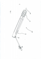
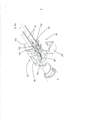
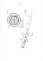
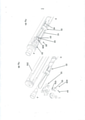
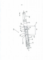
[0011] Fig. 1 - é uma vista em perspectiva superior de uma montagem de cabo de acordo com uma realização da presente invenção;[0011] Fig. 1 - is a top perspective view of a cable assembly according to an embodiment of the present invention;
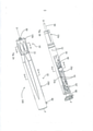
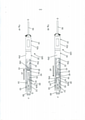
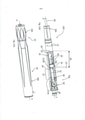
[0012] Figs. 2A e 2B são vistas em perspectiva mostrando a montagem de cabo externa e a montagem de cabo interna, de acordo com uma realização da presente invenção;[0012] Figs. 2A and 2B are perspective views showing the outer cable assembly and the inner cable assembly, in accordance with an embodiment of the present invention;
[0013] Fig. 2C - é uma vista explodida de uma montagem de cabo, de acordo com uma realização da presente invenção;[0013] Fig. 2C - is an exploded view of a cable assembly, according to an embodiment of the present invention;
[0014] Fig. 2D - é uma vista em seção transversal de um cabo orientável tomada ao longo da linha line 2D-2D da Fig.2A, de acordo com uma realização da presente invenção;[0014] Fig. 2D - is a cross-sectional view of a swivel cable taken along the
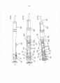
[0015] Fig. 3A-3B - são vistas em perspectiva de uma montagem deslizante de acordo com uma realização da presente invenção;[0015] Fig. 3A-3B - are perspective views of a slide assembly according to an embodiment of the present invention;
[0016] Fig. 3C - é uma vista em perspectiva superior de um deslizante em duas partes, de acordo com uma realização da presente invenção;[0016] Fig. 3C - is a top perspective view of a two-part slider, according to an embodiment of the present invention;
[0017] Fig. 3D - é uma vista em seção transversal de um cabo orientável tomada ao longo da linha 3D-3D da Fig. 2A, de acordo com uma realização da presente invenção;[0017] Fig. 3D - is a cross-sectional view of a swivel cable taken along the 3D-3D line of Fig. 2A, according to an embodiment of the present invention;
[0018] Fig. 3E - é uma vista em seção transversal de um cabo orientável tomada ao longo da linha 3E-3E da Fig. 2B, de acordo com uma realização da presente invenção;[0018] Fig. 3E - is a cross-sectional view of a swivel cable taken along the
[0019] Fig. 3F - ilustra uma vista em seção transversal superior, uma vista superior e uma vista lateral de uma montagem deslizante, de acordo com uma realização da presente invenção;[0019] Fig. 3F - illustrates a top cross-sectional view, a top view and a side view of a slide assembly, according to an embodiment of the present invention;
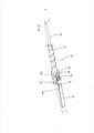
[0020] Fig. 3G - é uma vista em perspectiva de uma montagem de cabo interna com uma montagem deslizante de acordo com uma realização alternativa da presente invenção;[0020] Fig. 3G is a perspective view of an internal cable assembly with a slide assembly according to an alternative embodiment of the present invention;
[0021] Fig. 3H - é uma vista em seção transversal de uma montagem deslizante tomada ao longo da linha 3H-3H da Fig. 3G, de acordo com uma realização alternativa da presente invenção;[0021] Fig. 3H - is a cross-sectional view of a slide assembly taken along
[0022] Fig. 4A - é uma vista de extremidade de uma montagem de cabo de acordo com uma realização da presente invenção;[0022] Fig. 4A - is an end view of a cable assembly according to an embodiment of the present invention;
[0023] Fig. 4B - é uma vista em seção transversal lateral de uma montagem de cabo tomada ao longo da linha 4B-4B da Fig. 4A, de acordo com uma realização da presente invenção;[0023] Fig. 4B - is a side cross-sectional view of a cable assembly taken along line 4B-4B of Fig. 4A, in accordance with one embodiment of the present invention;
[0024] Fig. 4C - é uma vista em seção transversal lateral de uma montagem de cabo tomada ao longo da linha 4C-4C da Fig. 4A de acordo com uma realização da presente invenção;[0024] Fig. 4C - is a side cross-sectional view of a cable assembly taken along
[0025] Figs, 4D, 4E e 4F - ilustram a operação de uma montagem de cabo de acordo com uma realização da presente invenção;[0025] Figs, 4D, 4E and 4F - illustrate the operation of a cable assembly according to an embodiment of the present invention;
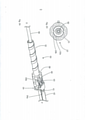
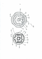
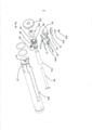
[0026] Fig. 5A - mostra uma vista em perspectiva superior de uma montagem de polia no interior de um cabo de acordo com uma realização da presente invenção;[0026] Fig. 5A - shows a top perspective view of a pulley assembly within a cable according to an embodiment of the present invention;
[0027] Fig. 5B - ilustra uma vista superior de uma montagem de polia no interior de um cabo de acordo com uma realização da presente invenção;[0027] Fig. 5B - illustrates a top view of a pulley assembly within a cable according to an embodiment of the present invention;
[0028] Fig. 5C - ilustra uma vista lateral de uma montagem de polia no interior de um cabo de acordo com uma realização da presente invenção;[0028] Fig. 5C - illustrates a side view of a pulley assembly within a cable according to an embodiment of the present invention;
[0029] Fig. 5D - é uma vista explodida de um cabo mostrando uma montagem de polia, de acordo com uma realização da presente invenção;[0029] Fig. 5D - is an exploded view of a cable showing a pulley assembly, in accordance with an embodiment of the present invention;
[0030] Fig. 5E - ilustra uma vista superior aumentada de uma montagem de polia, de acordo com uma realização da presente invenção;[0030] Fig. 5E - illustrates an enlarged top view of a pulley assembly, according to an embodiment of the present invention;
[0031] Fig. 5F - é uma vista em seção transversal de um cabo tomada ao longo da linha 5F-5F da Fig. 5A;[0031] Fig. 5F - is a cross-sectional view of a cable taken along the
[0032] Fig. 5G. - é uma vista em seção transversal de um cabo tomada ao longo da linha 5G-5G da Fig. 5B, de acordo com uma realização da presente invenção;[0032] Fig. 5G. - is a cross-sectional view of a cable taken along the
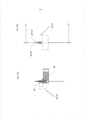
[0033] Fig. 6A - ilustra uma vista lateral de um elemento limitante ou de restrição, de acordo com uma realização da presente invenção;[0033] Fig. 6A - illustrates a side view of a limiting or restricting element, according to an embodiment of the present invention;
[0034] Fig. 6B - ilustra uma vista inferior de um elemento limitante ou de restrição, de acordo com uma realização da presente invenção;[0034] Fig. 6B - illustrates a bottom view of a limiting or restraining element, according to an embodiment of the present invention;
[0035] Fig. 7A-7B - são vistas laterais em perspectiva de um elemento limitante ou de restrição, de acordo com uma realização da presente invenção;[0035] Fig. 7A-7B - are perspective side views of a limiting or restraining element, according to an embodiment of the present invention;
[0036] Fig. 7C - é uma vista em seção de um elemento limitante ou de restrição ao longo da linha 7C-7C da Fig. 7B, de acordo com uma realização da presente invenção;[0036] Fig. 7C - is a sectional view of a limiting or restraining element along the
[0037] Fig. 8A - é uma vista em perspectiva de uma realização alternativa de um elemento limitante ou de restrição, de acordo com uma realização alternativa da presente invenção;[0037] Fig. 8A - is a perspective view of an alternative embodiment of a limiting or restraining element, according to an alternative embodiment of the present invention;
[0038] Fig. 8B - é uma vista explodida de uma montagem de cabo com uma realização alternativa de um elemento limitante ou de restrição de acordo com uma realização da presente invenção;[0038] Fig. 8B - is an exploded view of a cable assembly with an alternative embodiment of a limiting or restraining element according to an embodiment of the present invention;
[0039] Fig. 9A - é uma vista em perspectiva da montagem de cabo com uma realização alternativa de um elemento limitante ou de restrição, de acordo com uma realização alternativa da presente invenção;[0039] Fig. 9A - is a perspective view of the cable assembly with an alternative embodiment of a limiting or restraining element, according to an alternative embodiment of the present invention;
[0040] Fig. 9B - é uma vista em perspectiva de um elemento limitante ou de restrição, de acordo com uma realização da presente invenção.[0040] Fig. 9B - is a perspective view of a limiting or restricting element, according to an embodiment of the present invention.
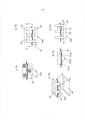
[0041] Figs 10A-10C - ilustram várias realizações de uma característica limitante de deslizamento ou bloqueio de deslizamento de acordo com várias realizações da presente invenção;[0041] Figs 10A-10C - illustrate various embodiments of a slip limiting or slip blocking feature in accordance with various embodiments of the present invention;
[0042] Figs 10D-10F - ilustram realizações alternativas de uma característica limitante de deslizamento ou bloqueio de deslizamento de acordo com várias realizações da presente invenção;[0042] Figs 10D-10F - illustrate alternative embodiments of a slip limiting or slip blocking feature in accordance with various embodiments of the present invention;
[0043] Figs 10G-10H - ilustram realizações alternativas adicionais de uma característica limitante de deslizamento ou bloqueio de deslizamento de acordo com várias realizações da presente invenção;[0043] Figs 10G-10H - illustrate further alternative embodiments of a slip limiting or slip blocking feature in accordance with various embodiments of the present invention;
[0044] Figs 11A-11B - ilustram uma realização alternativa de um friso, em vista lateral e em seções transversais, de acordo com uma realização da presente invenção; e[0044] Figs 11A-11B - illustrate an alternative embodiment of a frieze, in side view and in cross sections, according to an embodiment of the present invention; and
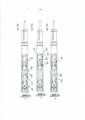
[0045] Figs 12A-12C - ilustram um cabo de acordo com realizações alternativas da presente invenção.[0045] Figs 12A-12C - illustrate a cable according to alternative embodiments of the present invention.
[0046] Com referência específica agora aos desenhos em detalhe, ressalta-se que as particularidades mostradas são como exemplo e para propósitos apenas de discussão ilustrativa de certas realizações da presente invenção. Antes de explicar pelo menos uma realização da invenção em detalhe, deve ser entendido que a invenção não está limitada em sua aplicação aos detalhes de construção e à disposição dos componentes apresentados na descrição a seguir ou ilustrados nos desenhos. A invenção é capaz de outras realizações ou de ser praticada ou realizada de várias maneiras. Também, deve ser entendido que a fraseologia e terminologia empregadas aqui têm o propósito de descrição e não devem ser encaradas como limitantes.[0046] With specific reference now to the drawings in detail, it is noted that the features shown are by way of example and for purposes of illustrative discussion only of certain embodiments of the present invention. Before explaining at least one embodiment of the invention in detail, it should be understood that the invention is not limited in its application to the construction details and arrangement of components shown in the description below or illustrated in the drawings. The invention is capable of other embodiments or of being practiced or performed in various ways. Also, it should be understood that the phraseology and terminology employed herein are for the purpose of description and should not be regarded as limiting.
[0047] Como uma visão geral, dispositivos médicos orientáveis apresentam vários usos e aplicações, tais como para orientação e posicionamento de dispositivos tal como cateteres, fios guias e semelhantes no interior do corpo de um paciente. Cabos utilizados com tais dispositivos orientáveis incluem tipicamente um mecanismo para acionar um ou mais fios de tensão capazes de defletir o dispositivo orientável e, desta forma, guiar uma ponta funcional de um dispositivo médico ali posicionada.[0047] As an overview, orientable medical devices have various uses and applications, such as for guiding and positioning devices such as catheters, guide wires and the like within a patient's body. Cables used with such steerable devices typically include a mechanism for driving one or more tension wires capable of deflecting the swiveling device and thereby guiding a working tip of a medical device positioned therein.
[0048] Durante a concepção e colocação em prática da presente invenção, os presentes inventores desenvolveram um desenho único para um sistema de controle bidirecional que provê um mecanismo de controle rotativo para operar um mecanismo deslizante de complexidade reduzida para aplicar tensão em dois ou mais fios de controle de maneira a alterar a deflexão de um dispositivo médico, tal como um cateter orientável. O mecanismo rotativo provê um controle melhorado do mecanismo deslizante para possibilitar deflexões precisas do dispositivo médico, enquanto que o mecanismo deslizante em si compreende um desenho relativamente simplificado em comparação com os produtos existentes.[0048] During the conception and practice of the present invention, the present inventors developed a unique design for a bidirectional control system that provides a rotary control mechanism to operate a sliding mechanism of reduced complexity to apply voltage to two or more wires. control to alter the deflection of a medical device, such as a steerable catheter. The rotary mechanism provides improved control of the slider mechanism to enable precise deflections of the medical device, while the slider mechanism itself comprises a relatively simplified design compared to existing products.
[0049] Como adicionalmente descrito abaixo, a presente invenção provê um mecanismo de controle rotativo tal como um botão onde a rotação do botão é convertida em uma força de tensão exercida separadamente sobre cada um dos dois fios de controle por meio de um mecanismo deslizante de complexidade reduzida compreendendo uma montagem deslizante móvel única que é acoplada, diretamente ou indiretamente, aos fios de controle. A força de tensão aplicada a cada um dos fios de controle resulta em uma alteração na deflexão do dispositivo médico, tal como um cateter orientável, ao qual estão acoplados. As realizações da presente invenção, desta forma, evitam a necessidade de se ter uma pluralidade de membros deslizantes, um para cada um dos fios de tensão.[0049] As further described below, the present invention provides a rotary control mechanism such as a knob where the rotation of the knob is converted into a tension force exerted separately on each of the two control wires by means of a slider mechanism. reduced complexity comprising a single movable slide assembly that is coupled, directly or indirectly, to the control wires. The tension force applied to each of the control wires results in a change in the deflection of the medical device, such as a steerable catheter, to which they are attached. Embodiments of the present invention thus obviate the need to have a plurality of sliding members, one for each of the tension wires.
[0050] Em um aspecto genérico, realizações da presente invenção provêm um mecanismo rotativo para controlar a deflexão de dois fios de controle (também chamados de fios de tensão) utilizando um membro móvel de maneira a permitir que um cateter ou outro dispositivo médico seja guiado em duas direções diferentes. A rotação do botão em uma primeira direção de rotação desloca o membro ao longo de uma direção longitudinal para permitir que um dos dois fios de tensão sejam tensionados (para defletir o cateter para uma primeira orientação) e rotação do botão em uma direção de rotação oposta (em torno de um eixo longitudinal do cabo) desloca o membro ao longo da direção longitudinal oposta para permitir que o outro dos dois fios de tensão seja tensionado (para defletir o cateter para uma orientação diferente).[0050] In a generic aspect, embodiments of the present invention provide a rotating mechanism to control the deflection of two control wires (also called tension wires) using a movable member in order to allow a catheter or other medical device to be guided. in two different directions. Rotation of the knob in a first direction of rotation displaces the limb along a longitudinal direction to allow one of the two tension threads to be tensioned (to deflect the catheter to a first orientation) and rotation of the knob in an opposite direction of rotation (about a longitudinal axis of the cable) displaces the limb along the opposite longitudinal direction to allow the other of the two tension wires to be tensioned (to deflect the catheter to a different orientation).
[0051] De acordo com uma realização, a presente invenção provê um sistema de controle para controle bidirecional de um cateter orientável, o cateter incluindo pelo menos dois fios de controle, uma extremidade distal de cada um dos fios de controle sendo acoplada ao cateter em uma região distal deste, o sistema de controle compreendendo: um alojamento acoplado ao cateter; uma montagem deslizante posicionada no interior do alojamento e operável para se deslocar linearmente; uma parte proximal de cada um dos pelo menos dois fios de controle sendo posicionada através da montagem deslizante; e um botão de controle acoplado de forma rotativa ao alojamento para deslocar linearmente a montagem deslizante, possibilitando assim que a montagem deslizante manipule separadamente cada um dos ditos pelo menos dois fios de controle para efetuar uma alteração na deflexão do dito cateter; onde a rotação do botão de controle em uma primeira direção de rotação causa o movimento distal da montagem deslizante em uma primeira direção linear fazendo com que a montagem deslizante aplique tensão em um dos ditos pelo menos dois fios de controle efetuando assim uma alteração na deflexão do dito cateter em uma primeira direção de deflexão e onde a rotação do botão em uma segunda direção de rotação causa o movimento proximal da montagem deslizante em uma segunda direção linear fazendo com que a montagem deslizante aplique tensão no outro dos ditos pelo menos dois fios de controle efetuando assim uma alteração na deflexão do dito cateter em uma segunda direção de deflexão.Visão geral da montagem de cabo[0051] In accordance with one embodiment, the present invention provides a control system for bidirectional control of a steerable catheter, the catheter including at least two control wires, a distal end of each of the control wires being coupled to the catheter in a distal region thereof, the control system comprising: a housing coupled to the catheter; a sliding assembly positioned within the housing and operable to move linearly; a proximal portion of each of the at least two control wires being positioned across the slide assembly; and a control knob rotatably coupled to the housing for linearly displacing the slide assembly, thereby enabling the slide assembly to separately manipulate each of said at least two control wires to effect a change in deflection of said catheter; where rotation of the control knob in a first direction of rotation causes the slide assembly to move distally in a first linear direction causing the slide assembly to apply tension to one of said at least two control wires thereby effecting a change in the deflection of the said catheter in a first direction of deflection and wherein rotation of the knob in a second direction of rotation causes proximal movement of the slide assembly in a second linear direction causing the slide assembly to apply tension to the other of said at least two control wires thereby effecting a change in the deflection of said catheter in a second deflection direction. Cable Assembly Overview
[0052] Em uma realização da presente invenção, é provido um sistema de controle orientável ou cabo (100) para manipular um dispositivo médico. O dispositivo médico pode incluir, sem limitação, um cateter, bainha, introdutor ou dispositivos médicos similares. Em um exemplo específico, como mostrado nas Figs. 1 e 2A, o cabo (100) é acoplado a uma bainha (90) para possibilitar que um usuário manipule ou oriente a bainha (90) em uma direção desejada durante o uso. O cabo (100) compreende um botão (10) que é acoplado de forma rotativa a um alojamento (20) no cabo. O botão (10) é rotativo em torno do eixo longitudinal do cabo (100) e gira em relação ao alojamento (20). Em operação, a rotação do botão (10) em uma primeira direção de rotação permite que o usuário oriente ou crie uma deflexão da bainha (90) em uma primeira direção, enquanto que rotação do botão (10) em uma segunda direção de rotação permite que o usuário oriente ou crie uma deflexão da bainha (90) em uma segunda direção. Em algumas realizações tais como descritas aqui, o cateter orientável bidirecional descrito é operável para ser defletido em duas direções de deflexão diferentes, uma primeira e um segunda direção de deflexão. Em outras realizações, o cateter orientável bidirecional é configurado para (ou apresenta funcionalidades internas que possibilitam a) defletir em duas direções de deflexão diferentes; entretanto, a deflexão do cateter em uma de suas direções de deflexão é limitada ou restrita de tal forma que a deflexão observada do cateter é limitada a uma única direção de deflexão (em relação à posição de partida ou neutra). Desta forma, em algumas realizações é provido um sistema de controle unidirecional para um cateter orientável bidirecional de maneira a prover um cateter orientável unidirecional incluindo pelo menos dois fios de controle.[0052] In one embodiment of the present invention, a steerable control system or cable (100) is provided for manipulating a medical device. The medical device may include, without limitation, a catheter, sheath, introducer or similar medical device. In a specific example, as shown in Figs. 1 and 2A, the cable (100) is coupled to a sheath (90) to enable a user to manipulate or orient the sheath (90) in a desired direction during use. The handle (100) comprises a button (10) which is rotatably coupled to a housing (20) on the handle. The knob (10) is rotatable about the longitudinal axis of the handle (100) and rotates with respect to the housing (20). In operation, rotating the knob (10) in a first direction of rotation allows the user to orient or create a deflection of the sheath (90) in a first direction, while rotation of the knob (10) in a second direction of rotation allows for the user to orient or deflect the hem (90) in a second direction. In some embodiments as described herein, the described bidirectional steerable catheter is operable to be deflected in two different deflection directions, a first and a second deflection direction. In other embodiments, the bidirectional steerable catheter is configured to (or has built-in functionality that makes it possible to a) deflect in two different deflection directions; however, the deflection of the catheter in one of its deflection directions is limited or constrained such that the observed deflection of the catheter is limited to a single deflection direction (relative to the starting or neutral position). Thus, in some embodiments, a unidirectional control system is provided for a bidirectional steerable catheter so as to provide a unidirectional steerable catheter including at least two control wires.
[0053] A rotação do botão (10) é convertida em uma deflexão da bainha (90) por meio de uma montagem deslizante (30), mostrada na Fig. 2B. Genericamente, o botão (10) é acoplado de forma cooperativa com a montagem deslizante (30) que é alojada no interior de um lúmen definido pelo alojamento (20) do cabo. Em um exemplo específico, o botão (10) é acoplado em rosca à montagem deslizante (30). A rotação do botão (10) causa um deslocamento linear correspondente da montagem deslizante (30) no interior do alojamento (20). Este deslocamento da montagem deslizante (30) é convertido em uma tensão nos fios de controle acoplados à montagem deslizante (30) e resulta assim em uma deflexão da bainha (90).[0053] The rotation of the knob (10) is converted to a deflection of the sheath (90) by means of a slide assembly (30), shown in Fig. 2B. Generally, the button (10) is cooperatively coupled with the slide assembly (30) which is housed within a lumen defined by the housing (20) of the cable. In a specific example, the knob (10) is threaded into the slide assembly (30). Rotation of the knob (10) causes a corresponding linear displacement of the slide assembly (30) within the housing (20). This displacement of the slide assembly (30) is converted into a tension in the control wires coupled to the slide assembly (30) and thus results in a deflection of the sheath (90).
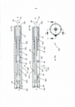
[0054] Mais especificamente, a montagem deslizante (30) é acoplada às respectivas extremidades proximais de um par de fios de controle que se estendem substancialmente ao longo do comprimento da bainha (90), por exemplo, os fios de controle (40) e (42) como mostrados na Fig. 2B. Uma extremidade distal (não mostrada) de cada um dos fios de controle (40, 42) é acoplada a uma parte distal da bainha (90). A rotação do botão (10) em uma direção faz com que a montagem deslizante (30) se desloque de forma proximal no interior do alojamento (20) puxando um dos fios de controle (tal como o fio de controle (40)) para defletir a bainha (90) em uma primeira direção, enquanto que a rotação do botão (10) em uma direção oposta faz com que a montagem deslizante (30) se desloque de forma distal no interior do alojamento (20) puxando o outro dos fios de controle (tal como o fio de controle (42)) para defletir a bainha (90) em uma segunda direção.[0054] More specifically, the slide assembly (30) is coupled to the respective proximal ends of a pair of control wires that extend substantially along the length of the sheath (90), e.g., the control wires (40) and (42) as shown in Fig. 2B. A distal end (not shown) of each of the control wires (40, 42) is coupled to a distal portion of the sheath (90). Rotating the knob (10) in one direction causes the slide assembly (30) to move proximally within the housing (20) pulling one of the control wires (such as the control wire (40)) to deflect the sheath (90) in a first direction, while rotation of the knob (10) in an opposite direction causes the slide assembly (30) to move distally within the housing (20) pulling the other of the threads of control (such as control wire (42)) to deflect the sheath (90) in a second direction.
[0055] Em um exemplo como mostrado na Fig. 2B, de maneira a permitir que a montagem deslizante (30) aplique separadamente um força de tensão sobre cada um dos dois fios de controle, um dos dois fios de controle (tal como o fio de controle (40)) é diretamente acoplado à montagem deslizante (30), enquanto que o outro fio de controle (tal como o fio de controle (42)) é indiretamente acoplado à montagem deslizante (30) por meio de um elemento de reversão de direção (50') tal como uma polia ou um pino. Em outras palavras, um meio para o acoplamento de extremidades distais dos fios em lados opostos do deslizante é incluído no cabo, pelo que o movimento do deslizante em uma direção irá aplicar tensão em um fio enquanto que o movimento do deslizante na outra direção irá aplicar tensão no outro fio. Conforme utilizado aqui o termo, "diretamente acoplado" significa que a extremidade proximal do fio é acoplada de forma operacional (mas não necessariamente fisicamente ligada ou integral com) ao deslizante sem passar através de uma estrutura intermediária, enquanto que "indiretamente acoplado" significa que a extremidade proximal do fio é acoplada de forma operacional (mas não necessariamente fisicamente ligada ou integral com) ao deslizante após passar através de uma estrutura ou elemento intermediário, tal como um elemento de reversão de direção.[0055] In an example as shown in Fig. 2B, in order to allow the slide assembly (30) to separately apply a tension force on each of the two control wires, one of the two control wires (such as the control wire (40)) is directly coupled to the slide assembly (30), while the other control wire (such as the control wire (42)) is indirectly coupled to the slide assembly (30) by means of a reversing element steering wheel (50') such as a pulley or pin. In other words, a means for coupling the distal ends of wires on opposite sides of the slider is included in the cable, whereby movement of the slider in one direction will apply tension to a wire while movement of the slider in the other direction will apply tension to a wire. voltage on the other wire. As used herein, "directly coupled" means that the proximal end of the wire is operatively coupled (but not necessarily physically bonded to or integral with) the slider without passing through an intermediate structure, while "indirectly coupled" means that the proximal end of the wire is operatively coupled to (but not necessarily physically bonded to or integral with) the slider after passing through an intermediate structure or element, such as a direction reversal element.
[0056] Em um exemplo específico, uma extremidade proximal do fio de controle (40) sai da bainha (90) e é direcionado de forma proximal através da montagem deslizante (30) para ser acoplada à ou a uma face proximal da montagem deslizante (30), isto é, de forma proximal à montagem deslizante. Desta forma, neste exemplo, o fio de controle (40) é "diretamente acoplado" à montagem deslizante (30). Similarmente, uma extremidade proximal do fio de controle (42) sai da bainha (90) e é direcionada de forma proximal através da montagem deslizante (30) onde sai da montagem deslizante (30). O fio de controle (42) é então passado em torno ou através do elemento de reversão de direção e direcionado de volta de forma distal de tal forma que pode ser passado de forma distal através do deslizante para ser acoplado à ou a um face distal da montagem deslizante (30), isto é, de forma distal à montagem deslizante. Desta forma, neste exemplo, o fio de controle (42) é "indiretamente acoplado" à montagem deslizante (30). Conforme utilizado aqui, o termo "face distal da montagem deslizante (30)" pode se referir a uma face distal de qualquer parte da montagem deslizante (30). Similarmente, a face proximal da montagem deslizante (30) pode se referir a uma face proximal de qualquer parte da montagem deslizante (30). Como um exemplo, os fios de controle saem da bainha (90) ao longo de uma parte do cabo (100) definida pelo botão (10) de maneira a minimizar quaisquer cantos excessivos e/ou estresses aplicados no fio quando acoplado à montagem deslizante (30).Visão geral do botão e alojamento[0056] In a specific example, a proximal end of the control wire (40) exits the sheath (90) and is directed proximally through the slide assembly (30) to be mated to or a proximal face of the slide assembly ( 30), i.e. proximal to the slide assembly. Thus, in this example, the control wire (40) is "directly coupled" to the slide assembly (30). Similarly, a proximal end of the control wire (42) exits the sheath (90) and is directed proximally through the slide assembly (30) where it exits the slide assembly (30). The control wire (42) is then passed around or through the reversing element and directed back distally such that it can be passed distally through the slider to be coupled to or with a distal face of the sliding assembly (30), i.e. distally to the sliding assembly. Thus, in this example, the control wire (42) is "indirectly coupled" to the slide assembly (30). As used herein, the term "distal face of slide assembly (30)" may refer to a distal face of any part of slide assembly (30). Similarly, the proximal face of the slide assembly (30) may refer to a proximal face of any part of the slide assembly (30). As an example, the control wires exit the sheath (90) along a portion of the handle (100) defined by the knob (10) so as to minimize any excessive corners and/or stresses applied to the wire when coupled to the slide assembly ( 30). Button and Housing Overview
[0057] Como mostrado na Fig. 2B, o alojamento (20) compreende uma parte interna (20a) (também chamada de alojamento interno (20a)) que define um lúmen que é envolto por uma parte externa do alojamento (20b) (também chamada de alojamento externo (20b)). Similarmente o botão (10) que é acoplado ao alojamento (20), compreende também uma parte interna do botão (10a) (também chamada de botão interno (10a)) definindo um lúmen através de uma parte externa do botão (10b) (também chamada de botão externo (10b)) que envolve o botão interno (10a). É provido um meio para fixar o botão interno (10a) no alojamento interno (20a). Em uma realização, uma parte do botão interno é recebida no interior do alojamento interno para permitir que um ou mais pinos (12) sejam inseridos transversalmente através do botão interno (10a) e do alojamento interno (20a) para os fixar no lugar. Os pinos (12) podem compreender um metal tal como aço inoxidável. Em um exemplo específico, podem ser providas aberturas ou orifícios (23) no alojamento interno (20a) e uma ranhura circunferencial (11) (como mostrado na Fig. 2C) pode ser provida em uma parte proximal do botão interno (10a), cada uma para receber os pinos (12). Os pinos (12) travam o botão interno (10a) e o alojamento interno (20a) entre si de maneira a prevenir o deslocamento longitudinal, enquanto que permitindo o movimento de rotação em relação entre si. Em outras palavras, o botão interno (10a) é livre para girar em relação ao alojamento interno (20a), enquanto que mantendo o acoplamento/travamento do botão interno (10a) em relação ao alojamento interno (20a). Em um exemplo específico, o cabo (100) compreende dois pinos (12) que acoplam o botão interno (10a) ao alojamento interno (20a). Em um exemplo, o botão (10) é posicionado na extremidade distal do cabo definindo a direção distal (D) e a extremidade oposta do alojamento (20) forma a extremidade proximal do cabo definindo a direção proximal (P), como mostrado nos desenhos. Em um exemplo alternativo, uma abertura ou orifício único (23) pode ser provido para receber um pino (12).[0057] As shown in Fig. 2B, the housing (20) comprises an internal part (20a) (also called the internal housing (20a)) that defines a lumen that is surrounded by an external part of the housing (20b) (also called external housing (20b)). Similarly, the button (10) which is coupled to the housing (20), also comprises an internal part of the button (10a) (also called the internal button (10a)) defining a lumen through an external part of the button (10b) (also called external button (10b)) that surrounds the internal button (10a). A means is provided for fixing the inner button (10a) in the inner housing (20a). In one embodiment, a portion of the inner knob is received within the inner housing to allow one or more pins (12) to be inserted transversely through the inner knob (10a) and inner housing (20a) to secure them in place. The pins (12) may comprise a metal such as stainless steel. In a specific example, openings or holes (23) may be provided in the inner housing (20a) and a circumferential groove (11) (as shown in Fig. 2C) may be provided in a proximal part of the inner button (10a), each one to receive the pins (12). The pins (12) lock the inner button (10a) and the inner housing (20a) together to prevent longitudinal displacement, while allowing rotational movement relative to each other. In other words, the inner knob (10a) is free to rotate with respect to the inner housing (20a), while maintaining the engagement/locking of the inner knob (10a) with respect to the inner housing (20a). In a specific example, the cable (100) comprises two pins (12) that couple the inner button (10a) to the inner housing (20a). In one example, the knob (10) is positioned at the distal end of the handle defining the distal direction (D) and the opposite end of the housing (20) forms the proximal end of the handle defining the proximal direction (P), as shown in the drawings. . In an alternative example, a single opening or hole (23) may be provided to receive a pin (12).
[0058] Em uma realização, como mostrada na Fig. 2C, o alojamento interno (20a) define um lúmen (24) através deste para alojar a montagem deslizante (30) e permitir o deslocamento da montagem deslizante (30) em seu interior. O alojamento interno (20a) compreende adicionalmente uma janela (26) que pode guiar a montagem deslizante (30) durante o deslocamento e pode prover também acesso para auxiliar no acoplamento dos fios de controle (40, 42), para a montagem deslizante (30). Em algumas realizações, o alojamento interno (20a) compreende adicionalmente uma ranhura ou trilha (21a) para guiar e limitar o deslocamento da montagem deslizante (30) (mostrado na Fig. 4B). Em uma realização, tanto o alojamento interno (20a) quanto o alojamento externo (20b) podem ser feitos de um polímero. Como um exemplo particular, o alojamento interno (20a) é feito de acrilonitrila butadieno estireno (ABS) e o alojamento externo (20b) é feito de polipropileno. Em outras realizações, o alojamento (20) pode ser feito de um metal.[0058] In one embodiment, as shown in Fig. 2C, the internal housing (20a) defines a lumen (24) therethrough to house the slide assembly (30) and allow displacement of the slide assembly (30) therein. The inner housing (20a) further comprises a window (26) which can guide the slide assembly (30) during displacement and may also provide access to assist in coupling the control wires (40, 42) to the slide assembly (30). ). In some embodiments, the inner housing (20a) further comprises a groove or track (21a) for guiding and limiting displacement of the slide assembly (30) (shown in Fig. 4B). In one embodiment, both the inner housing (20a) and the outer housing (20b) may be made of a polymer. As a particular example, the inner housing (20a) is made of acrylonitrile butadiene styrene (ABS) and the outer housing (20b) is made of polypropylene. In other embodiments, housing (20) may be made of a metal.
[0059] Em um exemplo, o botão externo (10b) compreende projeções que se estendem para dentro que são acopladas de forma cooperativa com ou se ajustam nas ranhuras no interior do botão interno (10a). Isto permite que o botão interno (10a) seja girado juntamente com o botão externo (10b). Desta forma, o movimento de rotação do botão externo (10b) é comunicado ao botão interno (10a) e estes podem ser operados como uma unidade única. Em uma realização, como mostrada nas Figs. 2B e 2C, o botão interno (10a) pode ser afunilado na direção da extremidade distal. O botão interno (10a) e o botão externo (10b) podem ser feitos também de um polímero. Como um exemplo particular, o botão interno (10a) é feito de DUPONT™ DELRIN® 100P e o botão externo (10b) é feito de polipropileno.[0059] In one example, the outer knob (10b) comprises inwardly extending projections that are cooperatively coupled with or fit into grooves within the inner knob (10a). This allows the inner knob (10a) to be rotated together with the outer knob (10b). In this way, the rotational movement of the outer knob (10b) is communicated to the inner knob (10a) and these can be operated as a single unit. In one embodiment, as shown in Figs. 2B and 2C, the inner button (10a) can be tapered towards the distal end. The inner button (10a) and the outer button (10b) can also be made of a polymer. As a particular example, the inner button (10a) is made of DUPONT™ DELRIN® 100P and the outer button (10b) is made of polypropylene.
[0060] Em algumas realizações, o botão externo (10b) pode apresentar uma garra externa para comodidade (15) disposta sobre este, como mostrado nas Fig. 1-2B. Um exemplo de uma garra (15) é adicionalmente mostrada em uma vista em seção transversal ilustrada na Fig. 2D. A garra de comodidade (15) pode ser feita de uma camada de elastômero que é moldada sobre uma parte do botão externo (10b). Em um exemplo particular, a garra externa de comodidade (15) é feita de Santoprene® SSA 55 que é moldado sobre uma parte do botão externo (10b) que é feito de polipropileno.Visão geral da montagem deslizante[0060] In some embodiments, the external button (10b) may have an external grip for convenience (15) disposed thereon, as shown in Fig. 1-2B. An example of a gripper (15) is additionally shown in a cross-sectional view illustrated in Fig. 2D. The convenience grip (15) may be made of an elastomer layer that is molded over a portion of the outer button (10b). In one particular example, the outer comfort grip (15) is made of Santoprene® SSA 55 which is molded over a portion of the outer button (10b) which is made of polypropylene. Slide mount overview
[0061] Em um exemplo específico mostrado na Fig. 3A, a montagem deslizante (30) compreende um parafuso (32) e um alojamento intermediário (38) compreendendo um carro (34). O carro (34) compreende uma face proximal (34a) e uma face distal (34b). Cada um dos fios de controle (40, 42) que sai da bainha (90) passa através do carro (34) com o fio de controle (40) sendo acoplado de forma operativa à face proximal (34a) do carro (34) utilizando-se um friso (41). O friso (41) substancialmente se apoia contra a face proximal (34a) e garante que conforme a montagem deslizante (30) se desloca de forma proximal esta puxa o fio (40) com ela. Similarmente, o fio de controle (42) é acoplado de forma operativa ao carro (34) utilizando-se um friso (43). O friso (43) substancialmente se apoia contra a face distal (34b) do carro (34) e garante que, conforme o carro (34) se desloca de forma distal, puxa o fio de controle (42) com ele. Como mostrado na Fig. 3B, o fio de controle (42) é inicialmente direcionado de forma proximal através do carro (34) e é então colocado como alça de tal forma que passa de forma distal através do carro (34) para ser acoplado à face distal (34b). Em algumas realizações, os fios de controle (40, 42) podem ser pré-frisados. Em outras realizações, os fios de controle (40, 42) podem ser frisados depois da montagem após terem sido direcionados através da montagem deslizante (30).Exemplo 1: Uma montagem deslizante em duas partes[0061] In a specific example shown in Fig. 3A, the slide assembly (30) comprises a screw (32) and an intermediate housing (38) comprising a carriage (34). The carriage (34) comprises a proximal face (34a) and a distal face (34b). Each of the control wires (40, 42) exiting the sheath (90) passes through the carriage (34) with the control wire (40) being operatively coupled to the proximal face (34a) of the carriage (34) using a frieze (41) is added. The flange (41) substantially rests against the proximal face (34a) and ensures that as the slide assembly (30) moves proximally it pulls the thread (40) with it. Similarly, the control wire (42) is operatively coupled to the carriage (34) using a crimp (43). The rib (43) substantially rests against the distal face (34b) of the carriage (34) and ensures that as the carriage (34) moves distally, it pulls the control wire (42) with it. As shown in Fig. 3B, the control wire (42) is initially routed proximally through the carriage (34) and is then looped in such a way that it passes distally through the carriage (34) to be coupled to the carriage (34). distal face (34b). In some embodiments, the control wires (40, 42) may be pre-crimped. In other embodiments, the control wires (40, 42) may be crimped after assembly after being routed through the slide assembly (30). Example 1: A two-part slide assembly
[0062] Em uma realização da montagem deslizante (30), o carro (34) do alojamento intermediário (38) pode compreender componentes múltiplos que são acoplados de forma cooperativa ou podem ser montados para forma o carro (34). Como um exemplo disto, como mostrado na Fig 3C e vista em seção transversal 3D, o carro (34) pode apresentar uma parte base (34') apresentando ranhuras (35x), (35y) e (35z) por meio das quais os fios (40) e (42) podem ser posicionados, e uma parte de cobertura ou um retentor de fio (34") que é acoplada à parte base (34') depois dos fios terem sido colocados para formar aberturas ou passagens (35x'), (35y') e (35z') através das quais os fios de controle (40, 42) podem deslizar. A parte de cobertura (34") pode ser fixada de forma destacável na parte base (34'), por exemplo, utilizando-se uma disposição de encaixe. A parte de cobertura (34") pode compreender projeções ou pernas (36) que se estendem para baixo, como mostrado na Fig. 3E, as quais são recebidas no interior de uma ranhura (37) no interior da parte base (34') do carro. As pernas (36) podem apresentar abas, tais como abas de encaixe, que podem ser travadas com a superfície da ranhura (37) de maneira a fixar a parte de cobertura (34") na parte base (34') .[0062] In one embodiment of the slide assembly (30), the carriage (34) of the intermediate housing (38) may comprise multiple components that are cooperatively coupled or may be assembled to form the carriage (34). As an example of this, as shown in Fig 3C and seen in 3D cross-section, the carriage (34) may have a base part (34') having grooves (35x), (35y) and (35z) through which the wires (40) and (42) can be positioned, and a cover part or a wire retainer (34") which is coupled to the base part (34') after the wires have been placed to form openings or passages (35x') , (35y') and (35z') through which the control wires (40, 42) can slide. The cover part (34") can be detachably fixed to the base part (34'), e.g. using a snap-in arrangement. The cover portion (34") may comprise downwardly extending projections or legs (36), as shown in Fig. 3E, which are received within a slot (37) within the base portion (34'). The legs (36) may have tabs, such as snap-in tabs, which can be locked with the surface of the groove (37) in order to secure the cover part (34") to the base part (34').
[0063] Adicionalmente, como mostrado na Fig. 3E, a parte base pode compreender uma ranhura (5w) através das quais os fios de controle (40) e (42) podem ser direcionados depois de saírem da bainha (90) de maneira a auxiliar na colocação dos fios através de cada uma das ranhuras (35x), (35y) e (35z). A parte de cobertura (34") pode compreender adicionalmente um ou mais dentes ou nervuras (35a) que interagem com as ranhuras (35x), (35y) e (35z) de maneira a formar parcialmente as passagens ou aberturas (35x'), (35y') e (35z') para reter os fios em seu interior. Em um exemplo, a parte de cobertura (34") compreende duas nervuras ou dentes (35a). Em outras realizações, as ranhuras podem ser posicionadas no interior da parte de cobertura (34"), ou ainda em outras realizações, as ranhuras podem ser posicionadas no interior tanto da parte base (34') quanto da parte de cobertura (34"), como mostrado na Fig. 3E. Em outras palavras, ou a parte base (34') e/ou a parte de cobertura (34") podem receber fios (40, 42) e formar aberturas (35x'), (35y') e (35z') no interior das quais os fios podem ser deslocados longitudinalmente. Em um exemplo, como mostrado, o fio de controle (42) pode ser direcionado através de aberturas ou passagens (35x') e (35z') que são localizadas para o exterior ou bordas laterais opostas da montagem deslizante (30) de maneira a prevenir estresse ou esforço excessivo sobre o fio de controle (42) e podem auxiliar em prevenir que a montagem deslizante (30) gire no interior do alojamento interno (20a) (enquanto o fio (40) é direcionado através da abertura ou passagem (35y')). Mais especificamente, o fio de controle (42) é direcionado forma proximal através da montagem deslizante (30) através da passagem (35x'), enrolado em torno da polia e direcionado de forma distal através da montagem deslizante (30) através da passagem (35z) para ser acoplado à face distal do carro (34). Em outras realizações, os fios (42) e (40) podem ser direcionados através de qualquer das aberturas ou passagens no interior do deslizante.[0063] Additionally, as shown in Fig. 3E, the base part may comprise a groove (5w) through which the control wires (40) and (42) may be routed after exiting the sheath (90) so as to assist in placing the wires through each of the slots (35x), (35y) and (35z). The cover part (34") may additionally comprise one or more teeth or ribs (35a) which interact with the grooves (35x), (35y) and (35z) so as to partially form the passages or openings (35x'), (35y') and (35z') to retain the threads therein. In one example, the covering part (34") comprises two ribs or teeth (35a). In other embodiments, the slots can be positioned inside the cover part (34"), or in still other embodiments, the slots can be positioned inside both the base part (34') and the cover part (34"). , as shown in Fig. 3E. In other words, either the base part (34') and/or the cover part (34") can receive wires (40, 42) and form openings (35x'), (35y') and (35z') inside of which the wires may be displaced longitudinally. In one example, as shown, the control wire (42) may be routed through openings or passages (35x') and (35z') which are located towards the outside or opposite side edges of the slide assembly (30) in order to prevent excessive stress or strain on the control wire (42) and can help prevent the slide assembly (30) from rotating within the inner housing (20a) (while the wire (40) is routed through the opening or passage (35y')) More specifically, the control wire (42) is routed proximally through the slide assembly (30) through the passage (35x'), wrapped around the pulley and directed from distal form through the sliding assembly (30) through the passage (35z) to be coupled to the distal face of the carriage (34). In other embodiments, wires (42) and (40) may be routed through any of the openings or passages within the slider.
[0064] Em algumas realizações, por exemplo, nas realizações ilustradas nas Figs. 3A-3F, a montagem deslizante (30) compreende um canal (39) [mostrado na Fig. 3F] que se estende através do parafuso (32), bem como através do carro (34) para permitir que uma parte da bainha (90) seja direcionada através do mesmo. Em um exemplo específico, a bainha (90) se estende substancialmente através de todo o comprimento do cabo (100) incluindo o botão (10), bem como o alojamento (20).Exemplo 2: Montagem deslizante formada integralmente[0064] In some embodiments, for example in the embodiments illustrated in Figs. 3A-3F, the slide assembly (30) comprises a channel (39) [shown in Fig. 3F] that extends through the screw (32) as well as through the carriage (34) to allow a portion of the sheath (90) ) is directed through it. In a specific example, the sheath (90) extends substantially through the entire length of the handle (100) including the button (10) as well as the housing (20). Example 2: Integrally formed slide assembly
[0065] Alternativamente, como mostrado na Fig. 3G, a parte base (34') e a parte de cobertura (34") podem ser formadas integralmente entre si. Em outras palavras, o carro (34) pode ser uma construção unitária e é formado de um componente único. Similar à realização descrita previamente, o carro (34) pode compreender três canais ou aberturas (35x'), (35y') e (35z') através das quais os fios (40) e (42) podem ser colocados respectivamente como mostrado na vista em seção transversal da Fig. 3H. Em um exemplo, o fio de controle (42) é direcionado através das aberturas (35x') e (35y') e o fio de controle (40) é direcionado através da abertura (35z'), em uma maneira similar à descrita acima.Realizações alternativas da montagem deslizante[0065] Alternatively, as shown in Fig. 3G, the base part (34') and the cover part (34") may be integrally formed with each other. In other words, the carriage (34) may be a unitary construction and is formed of a single component. Similar to the embodiment described previously, the carriage (34) may comprise three channels or openings (35x'), (35y') and (35z') through which the wires (40) and (42) can be placed respectively as shown in the cross-sectional view of Fig. 3H. In one example, the control wire (42) is routed through the openings (35x') and (35y') and the control wire (40) is directed through the opening (35z'), in a similar manner as described above. Alternative slide mount embodiments
[0066] Como discutido acima, a montagem deslizante (30) do cabo (100) (como mostrado na Fig. 4A) compreende um parafuso (32) apresentando uma disposição em roca externa que é recebido no interior do botão (10) apresentando uma disposição em rosca interna. Como mostrado nas Figs. 4B e 4C, isto permite que o botão (10) desloque o carro (34) da montagem deslizante (30) conforme é girado. Em um exemplo, a rosca externa do parafuso (32) pode ser na forma de uma rosca helicoidal (33a) que se acopla de forma cooperativa com uma rosca helicoidal interna (13) do botão interno (10a). Em alguns exemplos, a rosca helicoidal (33a) pode ser uma rosca externa contínua como mostrada na Fig. 3F e Figs. 4B-4C. Isto pode prover mais superfície de contato entre a rosca (33a) do parafuso (32) e a rosca interna (13) do botão interno (10a). Isto pode aumentar a fricção entre o parafuso (32) e o cabo interno e pode permitir um controle melhorado. Após o botão (10) ter sido girado, a fricção aumentada pode auxiliar em manter a posição do botão (10) em relação ao alojamento de maneira a reter a bainha (90) em sua deflexão desejada. Alternativamente, o parafuso (32) pode apresentar uma rosca descontínua ao longo de seu comprimento. Em algumas realizações, a montagem deslizante (30), incluindo o parafuso (32) é formada de um polímero. Mais particularmente, em um exemplo, a montagem deslizante (30) é feita de Dupont™ Delrin® 100P. Alternativamente, a montagem deslizante (30) pode ser de um termoplástico. Em ainda outras realizações, a montagem deslizante pode ser feita de um metal. Em algumas realizações, o parafuso (32) da montagem deslizante (30) pode apresentar uma superfície externa áspera para manter o acoplamento por fricção com o botão interno (10a). Em algumas realizações, o parafuso (32) com roscas externas (33a) é revestido com um lubrificante tal como um gel de fluorcarbono 807. Em uma realização, a rosca externa do parafuso (32) pode apresentar bordas afuniladas que formam uma saliência ou a rosca pode ser chanfrada, o que pode facilitar a manufatura da montagem deslizante (30), por exemplo, por meio de moldagem.Visão geral do elemento de reversão de direção[0066] As discussed above, the slide assembly (30) of the handle (100) (as shown in Fig. 4A) comprises a screw (32) having an external thread arrangement that is received within the knob (10) having a internal thread arrangement. As shown in Figs. 4B and 4C, this allows the knob (10) to move the carriage (34) of the slide assembly (30) as it is rotated. In one example, the external thread of the screw (32) may be in the form of a helical thread (33a) which cooperatively couples with an internal helical thread (13) of the internal knob (10a). In some examples, the helical thread (33a) may be a continuous external thread as shown in Fig. 3F and Figs. 4B-4C. This can provide more contact surface between the thread (33a) of the screw (32) and the internal thread (13) of the inner knob (10a). This may increase friction between the screw (32) and the inner cable and may allow for improved control. After the knob (10) has been rotated, the increased friction can assist in maintaining the position of the knob (10) with respect to the housing so as to retain the sheath (90) in its desired deflection. Alternatively, the screw (32) may have a discontinuous thread along its length. In some embodiments, the slide assembly (30) including the screw (32) is formed from a polymer. More particularly, in one example, the slide assembly (30) is made of Dupont™ Delrin® 100P. Alternatively, the slide assembly (30) may be of a thermoplastic. In still other embodiments, the slide assembly may be made of a metal. In some embodiments, the bolt (32) of the slide assembly (30) may have a roughened outer surface to maintain frictional engagement with the inner knob (10a). In some embodiments, the screw (32) with external threads (33a) is coated with a lubricant such as 807 fluorocarbon gel. In one embodiment, the external thread of the screw (32) may have tapered edges that form a ridge or the thread can be chamfered, which can facilitate the manufacture of the slide assembly (30), for example by means of molding.Overview of reversing direction element
[0067] Como mencionado acima, o fio (42) é passado através de um elemento de reversão de direção antes de ser acoplado à montagem deslizante (30). Em um exemplo específico, como mostrado na Fig. 5A, o fio (42) conforme sai da bainha (90) é passado em uma direção proximal através do carro (34) e então em torno de um elemento de reversão de direção (50') de tal forma que pode ser passado de forma distal através do carro (34) para ser acoplado à face distal (34b) do carro (34). Em uma realização específica, o elemento de reversão de direção é um pino. Em uma outra realização específica, como mostrado, o elemento de reversão de direção é uma montagem de polia (50) compreendendo uma polia (52), também mostrada na vista em seção transversal da Fig. 5G. A montagem de polia (50) pode ser acoplada ao alojamento interno (20a) utilizando-se um encaixe. Mais especificamente, com referência à Fig. 5A, o fio (42) conforme sai de forma proximal do carro (34), é direcionado sobre a montagem de polia (50) em torno da polia (52) e passado de forma distal através do carro (34) para ser acoplado à sua face distal (34b). Isto é também ilustrado nas Figs. 5B e 5C.Exemplo 1: Montagem de , polia[0067] As mentioned above, the wire (42) is passed through a direction reversal element before being coupled to the slide assembly (30). In a specific example, as shown in Fig. 5A, the wire (42) as it exits the sheath (90) is passed in a proximal direction through the carriage (34) and then around a reversing element (50'). ) such that it can be passed distally through the carriage (34) to be coupled to the distal face (34b) of the carriage (34). In a specific embodiment, the direction reversal element is a pin. In another specific embodiment, as shown, the reversing element is a pulley assembly (50) comprising a pulley (52), also shown in the cross-sectional view of Fig. 5G. The pulley assembly (50) can be coupled to the inner housing (20a) using a fitting. More specifically, with reference to Fig. 5A, the wire (42) as it exits proximally from the carriage (34), is directed over the pulley assembly (50) around the pulley (52) and passed distally through the carriage (34) to be coupled to its distal face (34b). This is also illustrated in Figs. 5B and 5C.Example 1: Assembly of , pulley
[0068] Em uma realização específica, como mostrada nas Figs. 5A-5B e 5D, a montagem de polia (50) compreende uma guia de altura (54) que auxilia em manter ou fixar o fio de controle (42) em torno da polia (52). A guia de altura (54) pode evitar que o fio de controle saia ou deslize para fora da polia (52) mantendo sua posição ao longo do plano da polia (52). Em um exemplo, a polia (52) pode compreender uma ranhura ou fenda ao longo de sua circunferência para permitir que o fio de controle (42) permaneça no lugar. A ranhura ou fenda (52') funciona para guiar e manter o fio de controle (42) em torno da polia (52). Adicionalmente, uma guia de polia (56) pode ser provida a qual é substancialmente adjacente e circunda circunferencialmente pelo menos uma parte da polia (52). O fio de controle (42) é guiado em torno da polia de tal forma que é posicionado entre a polia (52) e a guia de polia (56). A guia de polia (56) funciona para guiar e fixar o fio de controle (42) em torno da polia (52) de maneira a manter sua posição. Desta forma, a guia de altura (54) e a guia de polia (56) auxiliam em reter o fio de controle (42) em torno da polia. Como ilustrado na Fig. 5E, a guia de polia (56) pode compreender adicionalmente dentes ou projeções (56a) que restringem adicionalmente o movimento do fio de controle (42) para reduzir adicionalmente as chances de desalinhamento do fio de controle (42) e prevenir que o fio de controle (42) saia da polia (52). Os dentes ou projeções (56a) se estendem da guia de polia (56) para dentro na direção da polia (52) de maneira a controlar o movimento do fio de controle (42), como mostrado na Fig. 5E. Pelo provimento de uma ou mais projeções (56a) entre a guia de polia (56) e a polia (52), a quantidade de fricção entre o fio de controle (42) e a guia de polia (56) é aumentada. Em alguns exemplos, isto pode permitir que a polia (52) funcione como um pino. Em algumas realizações, cada uma entre a polia (52), guia de altura (54) e guia de polia (56) pode ser um componente separado ou pode ser formada integralmente com a montagem de polia (50), como mostrado. Em um exemplo específico, como mostrado nas Figs 5A-5E, e na vista em seção transversal mostrada na Fig. 5F, a polia (52) é montada em um pino (53) da montagem de polia (50). Uma arruela (55a) e um parafuso (55b) podem ser utilizados para fixar a polia (52) na montagem de polia (50). A montagem de polia (50) pode ser acoplada de forma cooperativa com o alojamento interno (20a). Em um exemplo, a arruela (55a) pode ser feita de aço inoxidável e o parafuso (55b) pode ser um parafuso alto-rosqueado que é feito de aço.[0068] In a specific embodiment, as shown in Figs. 5A-5B and 5D, the pulley assembly (50) comprises a height guide (54) that assists in maintaining or securing the control wire (42) around the pulley (52). The height guide (54) can prevent the control wire from protruding or slipping off the pulley (52) by maintaining its position along the plane of the pulley (52). In one example, the pulley (52) may comprise a groove or slot along its circumference to allow the control wire (42) to remain in place. The groove or slot (52') functions to guide and hold the control wire (42) around the pulley (52). Additionally, a pulley guide (56) may be provided which is substantially adjacent to and circumferentially surrounds at least a portion of the pulley (52). The control wire (42) is guided around the pulley such that it is positioned between the pulley (52) and the pulley guide (56). The pulley guide (56) functions to guide and secure the control wire (42) around the pulley (52) so as to maintain its position. In this way, the height guide (54) and the pulley guide (56) assist in retaining the control wire (42) around the pulley. As illustrated in Fig. 5E, the pulley guide (56) may additionally comprise teeth or projections (56a) that further restrict the movement of the control wire (42) to further reduce the chances of misalignment of the control wire (42) and prevent the control wire (42) from coming off the pulley (52). The teeth or projections (56a) extend from the pulley guide (56) inwardly towards the pulley (52) in order to control the movement of the control wire (42), as shown in Fig. 5E. By providing one or more projections (56a) between the pulley guide (56) and the pulley (52), the amount of friction between the control wire (42) and the pulley guide (56) is increased. In some examples, this may allow the pulley (52) to function as a pin. In some embodiments, each of the pulley (52), height guide (54) and pulley guide (56) may be a separate component or may be integrally formed with the pulley assembly (50), as shown. In a specific example, as shown in Figs 5A-5E, and in the cross-sectional view shown in Fig. 5F, the pulley (52) is mounted on a pin (53) of the pulley assembly (50). A washer (55a) and a bolt (55b) may be used to secure the pulley (52) to the pulley assembly (50). The pulley assembly (50) can be cooperatively coupled with the inner housing (20a). In one example, the washer (55a) may be made of stainless steel and the screw (55b) may be a tapped screw that is made of steel.
[0069] Em uma realização, a montagem de polia (50) é acoplada de forma destacável ao alojamento interno (20a) do cabo (100). Em um exemplo, a montagem de polia (50) é acoplada ao alojamento interno (20a) utilizando um ajuste por fricção. Mais especificamente, a montagem de polia (50) é acoplada ao alojamento (20) utilizando uma disposição de encaixe. Em um exemplo, a montagem de polia (50) pode compreender quatro pernas (57) (duas de cada lado da montagem de polia (50)), com cada uma das quatro pernas (57) apresentando projeções que se estendem lateralmente (57a) que são acopladas com aberturas (25) correspondentes no interior do alojamento interno (20a), como mostrado na Fig. 5D. Em um exemplo, a montagem de polia (50) pode ser acoplada ao alojamento interno (20a), após a bainha (90) ter sido inserida ao longo do alojamento interno (20a). A bainha (90) pode ser acoplada a um cubo (80) que pode ser também parcialmente posicionado no interior do alojamento interno (20a). Em um exemplo, o cubo (80) compreende um encaixe (85) para ser acoplado com uma capa de cubo (85b). Em um exemplo, o cubo (80) compreende nervuras (83) e uma ou mais chaves que se acoplam ou travam de forma cooperativa com ranhuras (27) correspondentes no interior do alojamento interno (20a). Isto provê um mecanismo de travamento rotativo que previne o deslocamento rotativo da bainha (90) em relação ao cabo (100). Uma vez posicionada a bainha (90) com o cubo (80) no interior do alojamento interno (20a), as projeções da montagem de polia (50) podem ser então acopladas de forma cooperativa com as aberturas (25) no interior do alojamento interno (20a). Isto pode permitir que o cubo (80) seja travado longitudinalmente de tal forma que o deslocamento longitudinal da bainha (90) em relação ao alojamento interno (20a) é limitado. Desta forma, em algumas realizações, o cabo de controle (100) provê tanto um mecanismo de travamento rotativo quanto um mecanismo de travamento longitudinal para a bainha (90). Em algumas realizações, o cubo (80) inclui uma porta (84) que se estende do cubo (80) e é envolvida pelo interior do alojamento externo (20b). Em algumas realizações, a montagem de polia (50) incluindo a polia (52) pode compreender um material biocompatível tal como um polímero. Em um exemplo, o polímero é o Dupont™ Delrin®. Em um exemplo específico, a montagem de polia (50) é feita de Dupont™ Delrin® 100P.Exemplo 2: Pin[0069] In one embodiment, the pulley assembly (50) is detachably coupled to the inner housing (20a) of the cable (100). In one example, the pulley assembly (50) is coupled to the inner housing (20a) using a friction fit. More specifically, the pulley assembly (50) is coupled to the housing (20) using a snap-in arrangement. In one example, the pulley assembly (50) may comprise four legs (57) (two on each side of the pulley assembly (50)), with each of the four legs (57) having laterally extending projections (57a) which are coupled with corresponding openings (25) inside the inner housing (20a), as shown in Fig. 5D. In one example, the pulley assembly (50) may be coupled to the inner housing (20a) after the sheath (90) has been inserted along the inner housing (20a). The sheath (90) may be coupled to a hub (80) which may also be partially positioned within the inner housing (20a). In one example, the hub (80) comprises a socket (85) to be coupled with a hub cap (85b). In one example, the hub (80) comprises ribs (83) and one or more keys that cooperatively engage or lock with corresponding grooves (27) within the inner housing (20a). This provides a rotary locking mechanism that prevents rotational displacement of the sheath (90) with respect to the handle (100). Once the sheath (90) with the hub (80) is positioned within the inner housing (20a), the projections of the pulley assembly (50) can then be cooperatively coupled with the openings (25) within the inner housing. (20a). This may allow the hub (80) to be longitudinally locked in such a way that the longitudinal displacement of the sheath (90) with respect to the inner housing (20a) is limited. Thus, in some embodiments, the control cable (100) provides both a rotary locking mechanism and a longitudinal locking mechanism for the sheath (90). In some embodiments, the hub (80) includes a door (84) that extends from the hub (80) and is enclosed by the interior of the outer housing (20b). In some embodiments, the pulley assembly (50) including the pulley (52) may comprise a biocompatible material such as a polymer. In one example, the polymer is Dupont™ Delrin®. In a specific example, the pulley assembly (50) is made of Dupont™ Delrin® 100P.Example 2: Pin
[0070] Em um exemplo alternativo, o elemento de reversão de direção pode compreender um pino ou outra estrutura para direcionar ou redirecionar um elemento alongado tal como um fio de tensão. Em tal exemplo, o fio (42), conforme sai de forma proximal do carro (34), pode ser direcionado sobre e/ou em torno do pino e passado de forma distal através do carro (34) para ser acoplado à sua face distal (34b) do carro (34). Em um exemplo específico, o pino se estende perpendicularmente ao plano no qual o fio de controle (42) se desloca. Em algumas realizações, o pino é posicionado de forma proximal em relação à montagem deslizante (30). Por exemplo, o pino pode ser acoplado a uma parte proximal da montagem de cabo (100). Alternativamente, o pino pode ser posicionado na montagem deslizante (30) ou ser acoplado à montagem deslizante (30). Em realizações em que o pino é utilizado, o fio de controle (42) que é direcionado de forma proximal a partir do carro (34) pode ser posto em alça em torno do pino de tal forma que possa ser direcionado de forma distal para ser acoplado à face distal (34b) do carro (34).Elemento de Limitação/Restrição de Folga[0070] In an alternative example, the direction reversal element may comprise a pin or other structure for directing or redirecting an elongated element such as a tension wire. In such an example, the wire (42), as it exits proximally from the carriage (34), may be directed over and/or around the pin and passed distally through the carriage (34) to be coupled to its distal face. (34b) of the car (34). In a specific example, the pin extends perpendicular to the plane in which the control wire (42) travels. In some embodiments, the pin is positioned proximally to the slide assembly (30). For example, the pin may be coupled to a proximal portion of the cable assembly (100). Alternatively, the pin may be positioned in the slide assembly (30) or be coupled to the slide assembly (30). In embodiments where the pin is used, the control wire (42) which is directed proximally from the carriage (34) may be looped around the pin such that it can be directed distally to be attached to the distal face (34b) of the carriage (34). Clearance Limiting/Restricting Element
[0071] Em uma realização da presente invenção, um ou mais elementos limitantes ou de restrição (60) podem ser providos no interior do cabo (100) que podem ser acoplados a um ou ambos os fios de controle (40, 42). Em um exemplo específico, é provido um elemento limitante de folga (60) que permite o acoplamento em fricção do fio de controle (42) para limitar ou restringir folga em uma parte do fio de controle (42). Em um exemplo, o elemento limitante ou de restrição (60) é acoplado à montagem de polia (50), como mostrado na Fig. 5A.Dispositivo de Fricção em Serpentina[0071] In one embodiment of the present invention, one or more limiting or restraining elements (60) may be provided within the cable (100) which may be coupled to one or both of the control wires (40, 42). In a specific example, a slack limiting element (60) is provided which allows frictional coupling of the control wire (42) to limit or restrict slack in a part of the control wire (42). In one example, the limiting or restraining element (60) is coupled to the pulley assembly (50) as shown in Fig. 5A. Serpentine Friction Device
[0072] Em uma realização específica, o elemento limitante ou de restrição (60) pode compreender um dispositivo de fricção em serpentina (60A), como mostrado pelas Figs. 4D-4F e Figs. 5A-5E. O dispositivo de fricção em serpentina (60A) compreende pinos (61) (como mostrado na Figs 5D) que se estendem perpendicularmente ao caminho do fio de controle (42) como mostrado nas Fig. 5E-5F e Fig. 6A. Como adicionalmente mostrado nas Figs 6A-6B, o fio de controle (42) é direcionado ou trançado através dos espaços, vazios ou aberturas (61s) definidos pelos pinos (61) e mantidos no lugar pelos pinos (61). O dispositivo de fricção em serpentina (60) pode compreender pinos (61) que são descentralizados entre si (por exemplo, deslocados lateralmente) e podem se sobrepor parcialmente entre si em relação ao eixo longitudinal do fio de controle (42). Em um exemplo específico, o dispositivo de fricção em serpentina (60A) compreende três pinos (61). Os dois pinos 61(a) e 61(c) mais externos podem ser posicionados de tal forma que fiquem fora do eixo a partir de um pino central (61b), como ilustrado na Fig. 6B. Como adicionalmente ilustrado nas Figs. 6A-6B, em um exemplo específico, o dispositivo de fricção em serpentina compreende pinos que são fixados uns aos outros ao longo de uma parte superior (66). Em outras realizações, o dispositivo de fricção em serpentina (60A) pode compreender nervuras ou superfícies ressaltadas com as quais o fio se acopla por fricção. O fio de controle (42) pode ser trançado através das nervuras de tal forma que acopla por fricção as nervuras.[0072] In a specific embodiment, the limiting or restraining element (60) may comprise a serpentine friction device (60A), as shown by Figs. 4D-4F and Figs. 5A-5E. The serpentine friction device (60A) comprises pins (61) (as shown in Figs 5D) that extend perpendicular to the control wire path (42) as shown in Figs 5E-5F and Fig 6A. As further shown in Figs 6A-6B, the control wire (42) is routed or braided through spaces, voids or openings (61s) defined by pins (61) and held in place by pins (61). The serpentine friction device (60) may comprise pins (61) that are off-center with each other (e.g., offset laterally) and may partially overlap with each other with respect to the longitudinal axis of the control wire (42). In a specific example, the serpentine friction device (60A) comprises three pins (61). The two outermost pins 61(a) and 61(c) can be positioned such that they are off-axis from a central pin (61b), as illustrated in Fig. 6B. As further illustrated in Figs. 6A-6B, in a specific example, the serpentine friction device comprises pins that are secured together along an upper portion (66). In other embodiments, the serpentine friction device (60A) may comprise ribs or raised surfaces with which the wire frictionally engages. The control wire (42) can be braided across the ribs in such a way that it frictionally couples the ribs.
[0073] Em um outro exemplo, como mostrado nas Figs. 7A, 7B e 7C, o dispositivo de fricção em serpentina (60A) pode compreender duas partes, uma parte base (62) e uma parte superior (66) com os pinos (61) se estendendo entre a parte base (62) e a parte superior (66). O fio de controle (42) pode ser passado através das aberturas (61s) entre cada um dos pinos (61) e a parte superior (66) pode ser utilizada para fixar o fio de controle (42) no local. Alternativamente, cada um dos pinos (61) é formado integralmente com a parte base (62) e a parte superior (66), respectivamente e o fio de controle (42) pode ser passado através das aberturas (65) antes de ser acoplado à montagem deslizante (30). Ainda adicionalmente, os pinos (61) podem ser fixados apenas à parte base (62).Dispositivo de Fricção Inclinado[0073] In another example, as shown in Figs. 7A, 7B and 7C, the serpentine friction device (60A) may comprise two parts, a base part (62) and an upper part (66) with the pins (61) extending between the base part (62) and the top (66). The control wire (42) can be passed through the openings (61s) between each of the pins (61) and the top (66) can be used to secure the control wire (42) in place. Alternatively, each of the pins (61) is formed integrally with the base part (62) and the top part (66), respectively, and the control wire (42) can be passed through the openings (65) before being coupled to the slide mount (30). Still additionally, the pins (61) can be fixed only to the base part (62).Inclined Friction Device
[0074] Em uma realização alternativa da presente invenção, o elemento limitante ou de restrição (60) compreende um dispositivo de fricção que é inclinado (60B) como mostrado nas Figs. 8A e 8B. O dispositivo de fricção inclinado (60B) pode ser acoplado à montagem de polia (50) que é operável de forma cooperativa para acoplar ao alojamento interno (20a). Em um exemplo, o dispositivo de fricção inclinado (60B) pode ser acoplado à montagem de polia (50) por meio de uma disposição de encaixe. O dispositivo de fricção (60B) compreende um bloco de fricção (63) e grampo (64) acoplado ao bloco de fricção (63). O bloco de fricção (63) pode definir uma abertura (63a) para receber o grampo (64). O grampo (64) pode ser inclinado na direção do bloco de fricção (63). Como mencionado antes, um ou ambos os fios de controle (40, 42) podem ser acoplados a um dispositivo de fricção inclinado (60B). Em um exemplo, o fio de controle (42) passa através do dispositivo de fricção inclinado (60B) de tal forma que é mantido entre o grampo (64) e o bloco de fricção (63). Em um exemplo, o grampo (64) compreende um mecanismo em mola. Em algumas realizações, o bloco de fricção (63) pode ser feito de um polímero. Em outras realizações, o bloco de fricção (63) pode ser feito de um elastômero e o grampo (64) pode ser feito de metal. Em um exemplo, o bloco de fricção (63) pode ser feito de borracha e o grampo compreender um fio e fricção pode ser criada entre o fio e a borracha. Em algumas realizações, o mecanismo de inclinação do grampo (64), por exemplo, uma mola pode ser ajustável.Dispositivo de Fricção Resiliente[0074] In an alternative embodiment of the present invention, the limiting or restricting element (60) comprises a friction device that is inclined (60B) as shown in Figs. 8A and 8B. The inclined friction device (60B) may be coupled to the pulley assembly (50) which is cooperatively operable to couple with the inner housing (20a). In one example, the inclined friction device (60B) may be coupled to the pulley assembly (50) by means of a snap-in arrangement. The friction device (60B) comprises a friction block (63) and clamp (64) coupled to the friction block (63). The friction block (63) may define an opening (63a) to receive the clamp (64). The clamp (64) can be tilted towards the friction block (63). As mentioned before, one or both of the control wires (40, 42) can be coupled to an inclined friction device (60B). In one example, the control wire (42) passes through the inclined friction device (60B) such that it is held between the clamp (64) and the friction block (63). In one example, the clamp (64) comprises a spring mechanism. In some embodiments, the friction block (63) may be made of a polymer. In other embodiments, the friction block (63) can be made of an elastomer and the clamp (64) can be made of metal. In one example, the friction block (63) can be made of rubber and the clamp comprises a wire and friction can be created between the wire and the rubber. In some embodiments, the tilting mechanism of the clamp (64), for example a spring, may be adjustable. Resilient Friction Device
[0075] Em ainda uma outra realização, o dispositivo de fricção pode compreender um dispositivo de fricção resiliente (60C) para acoplamento em fricção do fio de controle (42). Em um exemplo, o dispositivo de fricção resiliente (60C) pode compreender um bloco de elastômero (67a) como mostrado nas Fig. 9 A e 9B. Em uma realização, o bloco de elastômero (67a) pode compreender um bloco de borracha. O bloco de elastômero (67a) pode definir uma fenda (67b) se estendendo longitudinalmente ao longo de seu comprimento. Um fio de controle, por exemplo, o fio de controle (42), pode ser guiado no interior da abertura da fenda (67b). A fenda (67b) pode definir duas pernas que se estendem para baixo (68) do bloco de elastômero (67a). O fio de controle (42) pode ser acoplado em fricção pelas pernas que se estendem para baixo (68) e mantido entre as pernas (68).Elemento de Restrição ou Limitação de DeslizamentoExemplo 1: trilha no interior do alojamento do cabo[0075] In yet another embodiment, the friction device may comprise a resilient friction device (60C) for frictionally coupling the control wire (42). In one example, the resilient friction device (60C) may comprise an elastomer block (67a) as shown in Figs. 9A and 9B. In one embodiment, the elastomer block (67a) may comprise a rubber block. The elastomer block (67a) may define a slot (67b) extending longitudinally along its length. A control wire, for example the control wire (42), can be guided inside the slot opening (67b). The slot (67b) may define two downwardly extending legs (68) of the elastomer block (67a). The control wire (42) may be frictionally coupled by the downwardly extending legs (68) and held between the legs (68). Slip Restraining or Limiting ElementExample 1: track inside cable housing
[0076] Em algumas realizações, o alojamento interno (20a) é configurado para guiar a montagem deslizante (30) ao longo de um caminho linear no interior do alojamento interno (20a). Em um exemplo mostrado anteriormente nas Figs. 3E e 4B, o alojamento interno (20a) compreende uma ranhura ou trilha (21a) que corre substancialmente ao longo do comprimento do alojamento interno (20a). A montagem deslizante (30) pode compreender uma projeção ressaltada (31a) (ver, por exemplo, a Figure 3E) ao longo da base da montagem deslizante (30) que é acoplada de forma cooperativa no interior da trilha (21a) de maneira a auxiliar na manutenção do deslocamento linear da montagem deslizante (30) ao longo da trilha (21a).[0076] In some embodiments, the inner housing (20a) is configured to guide the slide assembly (30) along a linear path within the inner housing (20a). In an example shown earlier in Figs. 3E and 4B, the inner housing (20a) comprises a groove or track (21a) running substantially along the length of the inner housing (20a). The slide assembly (30) may comprise a raised projection (31a) (see, for example, Figure 3E) along the base of the slide assembly (30) which is cooperatively coupled within the track (21a) so as to assist in maintaining the linear displacement of the slide assembly (30) along the track (21a).
[0077] A trilha (21a) pode funcional adicionalmente como um bloqueio de deslizamento para restringir o movimento da montagem deslizante (30) para permitir uma deflexão desejada da bainha (90). Em outras palavras, o comprimento da trilha (21a) restringe a distância que a montagem deslizante (30) pode se deslocar em uma dada direção (ou na direção proximal e/ou na direção distal) que pode ser utilizado para restringir a quantidade de deflexão da bainha (90). A ranhura ou trilha (21a) define uma parede de extremidade (21a') em cada uma de suas extremidades opostas como mostrado nas Figs. 4B e 10A. Uma vez que a projeção ressaltada (31a) da montagem deslizante (30) alcançou a extremidade da trilha, esta se apóia contra a parede (21a') na extremidade da ranhura ou trilha (21a) interrompendo a montagem deslizante (30) (como mostrado na Fig. 10a, a ranhura ou trilha (21a) funciona como um bloqueio de deslizamento na ausência de um bloqueio de deslizamento tubular (21b) discutido mais abaixo). As Figs 10a e 10b ilustram ranhuras (21a) de diferentes comprimentos e, como tal, a distância em que se deslocou a montagem deslizante (30) é diferente para cada uma das realizações mostradas nas Figs. 10a e 10b.[0077] The track (21a) may additionally function as a slide lock to restrict movement of the slide assembly (30) to allow a desired deflection of the sheath (90). In other words, the length of the track (21a) restricts the distance that the slide assembly (30) can travel in a given direction (or in the proximal direction and/or in the distal direction) which can be used to restrict the amount of deflection. of the sheath (90). The groove or track (21a) defines an end wall (21a') at each of its opposite ends as shown in Figs. 4B and 10A. Once the raised projection (31a) of the slide assembly (30) has reached the end of the track, it rests against the wall (21a') at the end of the groove or track (21a) interrupting the slide assembly (30) (as shown). in Fig. 10a, the groove or track (21a) functions as a slide lock in the absence of a tubular slide lock (21b) discussed further below). Figs 10a and 10b illustrate slots (21a) of different lengths and, as such, the distance the slide assembly (30) has moved is different for each of the embodiments shown in Figs. 10a and 10b.
[0078] Em uma realização alternativa adicional, um bloqueio de comprimento ajustável pode ser provido acoplado à trilha (21a) (pode ser acoplado com a trilha (21a) pela utilização de uma disposição de encaixe ou pode ser acoplado a esta utilizando-se qualquer outro meio tal como uma fixação por fricção ou por cola). O bloqueio de comprimento ajustável pode compreender um braço que se estende para fora e pode ser acoplado com a montagem deslizante (30) evitando assim o deslocamento da montagem deslizante (30). Em um outro exemplo, como mostrado na Fig. 10c, o bloqueio de comprimento ajustável pode ser um pino (21z) que pode ser inserido na extremidade da ranhura ou trilha (21a) [por exemplo, no interior da ranhura da Fig. 10b] próximo à parede (21a') de maneira a encurtar o comprimento da trilha. Em outras palavras, o pino (21z) é provido para interagir com a trilha (21a) de maneira a alterar o comprimento da trilha (21a). Em algumas realizações, o pino (21z) pode ser inserido dentro da trilha (21a) próximo à montagem deslizante (30). Em outras realizações, o pino (21z) pode ser inserido dentro da trilha (21a) distal à montagem deslizante (30). Ainda adicionalmente, o bloqueio de comprimento ajustável pode ser na forma de um bloco ou um braço que pode ser fixado no interior da trilha e funcionar efetivamente para encurtar o comprimento da trilha (21a).Exemplo 2: Bloqueio de deslizamento tubular[0078] In a further alternative embodiment, an adjustable length lock may be provided coupled to the track (21a) (it may be coupled to the track (21a) using a snap-in arrangement or may be coupled to it using any other means such as friction or glue attachment). The length-adjustable lock may comprise an arm that extends outward and can be coupled with the slide assembly (30) thus preventing displacement of the slide assembly (30). In another example, as shown in Fig. 10c, the length-adjustable lock may be a pin (21z) that can be inserted into the end of the groove or track (21a) [e.g., inside the groove of Fig. 10b] close to the wall (21a') in order to shorten the length of the track. In other words, the pin (21z) is provided to interact with the track (21a) in order to change the length of the track (21a). In some embodiments, the pin (21z) can be inserted into the track (21a) near the slide assembly (30). In other embodiments, the pin (21z) can be inserted into the track (21a) distal to the slide assembly (30). Still additionally, the adjustable length lock can be in the form of a block or an arm that can be fixed inside the track and work effectively to shorten the length of the track (21a).Example 2: Tubular Slip Lock
[0079] Em algumas realizações, o elemento de restrição de deslizamento compreende um bloqueio de deslizamento tubular (21b) como mostrado nas Figs. 2A-2C, 4B-4C, 5A, 5D e 10D. Como um exemplo, o bloqueio de deslizamento tubular (21b) é montado na bainha (90) em um lado proximal da montagem deslizante (30). Em algumas realizações, o bloqueio de deslizamento tubular (21b) pode compreender uma peça de tubulação dura ou rígida que se apoia contra um cubo da bainha e pode compreender entalhes para permitir o acoplamento entre os mesmos e com o alojamento interno (20a). Em um exemplo, uma união por cola pode ser provida entre o bloqueio de deslizamento tubular (21b) e o cubo sobre o qual é montado. Em algumas realizações, a superfície de contato entre o bloqueio de deslizamento tubular (21b) e o cubo (80) pode ser aumentada pela adesão do bloqueio de deslizamento tubular (21b) ao cubo. Em algumas realizações, o bloqueio de deslizamento tubular (21b) pode apresentar entalhes adicionais para interagir com a montagem de polia (50) e o alojamento interno (20a). Em algumas realizações, como mostradas nas Fig. 4B e Fig. 10d, o bloqueio de deslizamento tubular (21b) pode se apoiar contra e/ou interagir com a montagem de polia (50). Em outras realizações, o bloqueio de deslizamento tubular (21b) pode ser montado na bainha e pode não ser fixo. O bloqueio de deslizamento tubular (21b) pode compreender um material relativamente flexível ou macio/resiliente tal como um polietileno de baixa densidade (LDPE). Em algumas realizações, o bloqueio de deslizamento tubular (21b) pode compreender um material relativamente mais duro ou mais rígido. Em um exemplo específico, o bloqueio de deslizamento tubular (21b) compreende um polietileno de alta densidade (HDPE). Alternativamente, o bloqueio de deslizamento tubular pode ser feito de aço inoxidável. Em um exemplo, o bloqueio de deslizamento tubular (21b) é um cilindro. Alternativamente, o bloqueio de deslizamento tubular (21b) é formado de um segmento de um cilindro. Em algumas realizações, o diâmetro interno do bloqueio de deslizamento tubular (21b) pode ser maior que o diâmetro externo da bainha (90) sobre a qual está montado. O bloqueio de deslizamento tubular define uma parede distal (21b') que interage com a montagem deslizante (30) para a interromper.[0079] In some embodiments, the slip restraining element comprises a tubular slip lock (21b) as shown in Figs. 2A-2C, 4B-4C, 5A, 5D and 10D. As an example, the tubular slide lock (21b) is mounted to the sheath (90) on a proximal side of the slide assembly (30). In some embodiments, the tubular slide lock (21b) may comprise a piece of hard or rigid tubing that rests against a hub of the sheath and may comprise notches to permit coupling therebetween and with the inner housing (20a). In one example, a glue joint may be provided between the tubular slide lock (21b) and the hub on which it is mounted. In some embodiments, the contact surface between the tubular slide block (21b) and the hub (80) can be increased by adhering the tubular slide block (21b) to the hub. In some embodiments, the tubular slide lock (21b) may have additional notches to interact with the pulley assembly (50) and inner housing (20a). In some embodiments, as shown in Fig. 4B and Fig. 10d, the tubular slide lock (21b) may lean against and/or interact with the pulley assembly (50). In other embodiments, the tubular slide lock (21b) may be mounted on the sheath and may not be secured. The tubular slide lock (21b) may comprise a relatively flexible or soft/resilient material such as low density polyethylene (LDPE). In some embodiments, the tubular slide lock (21b) may comprise a relatively stiffer or stiffer material. In a specific example, the tubular slide lock (21b) comprises a high density polyethylene (HDPE). Alternatively, the tubular slide lock can be made of stainless steel. In one example, the tubular slide lock (21b) is a cylinder. Alternatively, the tubular slide lock (21b) is formed from a segment of a cylinder. In some embodiments, the inner diameter of the tubular slide lock (21b) may be greater than the outer diameter of the sheath (90) on which it is mounted. The tubular slide lock defines a distal wall (21b') that interacts with the slide assembly (30) to stop it.
[0080] Em ainda outras realizações, como mostradas na Fig. 10e, o bloqueio de deslizamento tubular (21b) pode ser na forma de um colar (21y) (definindo uma parede proximal (21y')) que é ajustado sobre o parafuso (32) da montagem deslizante (30) em um lado distal da montagem deslizante (30). Alternativamente, a faixa de deslocamento da montagem deslizante (30) pode ser alterada pela redução ou aumento do comprimento do parafuso (32) da montagem deslizante (30). Em uma alternativa adicional, o bloqueio de deslizamento tubular (21b) pode ser formado como uma parte da montagem de polia (50) e pode se estender a partir desta para dentro do alojamento interno (20a).Exemplo 3: Uma barra se estendendo através do alojamento interno[0080] In still other embodiments, as shown in Fig. 10e, the tubular slide lock (21b) may be in the form of a collar (21y) (defining a proximal wall (21y')) that is fitted over the screw ( 32) of the slide assembly (30) on a distal side of the slide assembly (30). Alternatively, the range of travel of the slide mount (30) can be changed by reducing or increasing the length of the screw (32) of the slide mount (30). In a further alternative, the tubular slide lock (21b) may be formed as a part of the pulley assembly (50) and may extend therefrom into the inner housing (20a). Example 3: A bar extending through from the internal accommodation
[0081] Em realizações alternativas, como mostradas na Fig. 10f, o bloqueio de deslizamento ou característica limitante ou de restrição de deslizamento pode compreender uma barra (21c) se estendendo lateralmente através do alojamento interno (20a). Em outras palavras, a barra (21c) se estende através da largura do alojamento interno (20a). A barra (21c) pode ser posicionada entre a montagem deslizante (30) e a montagem de polia (50) com a barra definindo uma parede distal (21c').Exemplo 4: O bloqueio de deslizamento compreende um rebite[0081] In alternative embodiments, as shown in Fig. 10f, the slip blocking or slip limiting or restricting feature may comprise a bar (21c) extending laterally through the inner housing (20a). In other words, the bar (21c) extends across the width of the inner housing (20a). The bar (21c) can be positioned between the slide assembly (30) and the pulley assembly (50) with the bar defining a distal wall (21c'). Example 4: The slide lock comprises a rivet
[0082] Em algumas realizações, como mostrado na Fig. 10g, o bloqueio de deslizamento pode compreender um rebite (21d). Alternativamente, o bloqueio de deslizamento pode ser na forma de um pino ou um parafuso. O rebite (21d) é posicionado através de uma abertura na ranhura ou trilha (21a) no interior do alojamento interno (20a) e se estende para dentro do lúmen do alojamento interno (20a) na forma de uma projeção que se estende verticalmente para cima. O rebite (21d) pode ser fixado no alojamento interno através de um encaixe por fricção. O rebite (21d) é posicionado no caminho da montagem deslizante (30) e funciona para restringir seu movimento. Alternativamente, o rebite (21d) pode ser acoplado a um componente secundário tal como um bloco que é posicionado no interior do alojamento interno (20a) e funciona para bloquear a montagem deslizante (30).[0082] In some embodiments, as shown in Fig. 10g, the slide lock may comprise a rivet (21d). Alternatively, the slide lock may be in the form of a pin or a screw. The rivet (21d) is positioned through an opening in the groove or track (21a) within the inner housing (20a) and extends into the lumen of the inner housing (20a) in the form of a vertically upward projection. . The rivet (21d) can be fixed in the internal housing by means of a friction fit. The rivet (21d) is positioned in the path of the slide assembly (30) and functions to restrict its movement. Alternatively, the rivet (21d) may be coupled to a secondary component such as a block which is positioned within the inner housing (20a) and functions to lock the slide assembly (30).
[0083] Alternativamente, pode ser provido um acionador no cabo que permite o ajuste da característica limitante de deslizamento pelo usuário antes ou durante o uso de tal forma que o raio de curvatura máximo da bainha (90) e um ou ambas as direções pode ser ajustado. Em algumas realizações, o acionador pode ser na forma de um botão.Exemplo 5: Bloqueio de deslizamento é uma extensão da montagem de polia[0083] Alternatively, a trigger may be provided on the handle which allows adjustment of the slip limiting characteristic by the user before or during use such that the maximum bend radius of the sheath (90) and one or both directions can be adjusted. In some embodiments, the trigger may be in the form of a button.Example 5: Slip lock is an extension of the pulley assembly
[0084] Em ainda uma alternativa adicional, o componente de restrição de deslizamento ou bloqueio de deslizamento pode compreender uma extensão (21e) da montagem de polia (50), como mostrado na Fig. 10h, que se estende de forma distal para dentro do lúmen do alojamento interno (20a).[0084] In yet a further alternative, the slip restraining or slip blocking component may comprise an extension (21e) of the pulley assembly (50), as shown in Fig. 10h, which extends distally into the pulley assembly (50) as shown in Fig. 10h. internal housing lumen (20a).
[0085] Em algumas realizações, os fios de controle (40, 42) são feitos de uma metal. Mais especificamente, em um exemplo, os fios (40, 42) são de aço inoxidável. Em algumas realizações, os fios (40, 42) são um fio de aço inoxidável obtido da série 300. Em algumas realizações, pelo menos um dos fios de controle (40, 42) é um fio redondo. Em outras realizações, pelo menos um dos fios de controle (40, 42) é um fio chato que pode ser um fio retangular. Em uma realização específica, os fios (40, 42) são feitos de aço inoxidável 304V. Em um exemplo, os fios (40, 42) apresentam uma seção transversal de cerca de 0,004" x 0,015". Em um outro exemplo, os fios (40, 42) apresentam uma seção transversal de cerca de 0,004" x 0,012".[0085] In some embodiments, the control wires (40, 42) are made of a metal. More specifically, in one example, the wires (40, 42) are stainless steel. In some embodiments, the wires (40, 42) are a stainless steel wire obtained from the 300 series. In some embodiments, at least one of the control wires (40, 42) is a round wire. In other embodiments, at least one of the control wires (40, 42) is a flat wire which may be a rectangular wire. In a specific embodiment, the wires (40, 42) are made of 304V stainless steel. In one example, the wires (40, 42) have a cross section of about 0.004" x 0.015". In another example, the wires (40, 42) have a cross section of about 0.004" x 0.012".
[0086] Como mostrado nas Figs. 11A e 11B, em algumas realizações, os frisos (41, 43) podem ser um friso ajustável. Em um exemplo, o friso ajustável pode ser uma montagem de porca e parafuso. Em uma realização, o friso ajustável pode ser um parafuso (48) com rosca externa que se acopla de forma cooperativa com as roscas internas dentro da porca (46). Uma parte em friso cilíndrica (41', 43') é mantida parcialmente no interior do parafuso (48). O comprimento inicial dos fios (40) e (42) pode ser ajustado pelo ajuste da posição do parafuso (48) em relação à porca (46). Em algumas realizações, uma ou mais das aberturas (35x'), (35y') e (35z') no interior do carro (34) podem apresentar um diâmetro suficiente para acomodar o parafuso (48). Em outras realizações, os frisos (41, 43) podem não ser frisos ajustáveis.Bainha e Cubo[0086] As shown in Figs. 11A and 11B, in some embodiments, the ribs (41, 43) may be an adjustable rib. In one example, the adjustable rib may be a nut and bolt assembly. In one embodiment, the adjustable crimp may be an externally threaded bolt (48) that cooperatively couples with the internal threads within the nut (46). A cylindrical crimped portion (41', 43') is held partially within the screw (48). The initial length of the wires (40) and (42) can be adjusted by adjusting the position of the screw (48) in relation to the nut (46). In some embodiments, one or more of the openings (35x'), (35y') and (35z') within the carriage (34) may have a diameter sufficient to accommodate the screw (48). In other embodiments, the ribs (41, 43) may not be adjustable ribs. Scabbard and Hub
[0087] Em algumas realizações, a bainha (90) pode se estender através do cabo (100) a partir da extremidade proximal para a extremidade distal do cabo (100) como mostrado nas Figs. 2A-2C. Isto é adicionalmente ilustrado na vista em seção transversal das Fig. 4B-4C. Em uma realização, a bainha (90) é acoplada a um cubo (80) em sua extremidade proximal como adicionalmente mostrado nas Figs 2C e 5D. O cubo apresenta uma porta lateral (84) definindo uma abertura através do mesmo. Em um exemplo, a porta lateral (84) pode ser em ângulo. Em uma realização, a porta lateral (84) pode ser em um ângulo de cerca de 60° em relação ao eixo longitudinal do cubo (80). Em outras realizações, qualquer outro ângulo adequado pode ser utilizado. Como mostrado na Fig. 2C, a porta lateral é conectada a um torneira (92), por exemplo, uma torneira de 3 vias através da tubulação (94) que, em um exemplo, pode ser uma tubulação de poliuretana. A porta lateral em ângulo (84) pode aumentar a utilização do cabo (100) garantindo que a porta lateral (84) e a torneira (92) acopladas a este permaneçam fora do alcance do usuário, durante o uso do cabo (100). Em alguns exemplos, a porta lateral (84) pode ser utilizada como um ponto de referência de maneira a orientar a ponta distal da bainha (90). Em um exemplo, a abertura definida pela porta lateral pode permitir que os médicos injetem fluido, por exemplo, solução salina ou contraste através da bainha durante o procedimento. Em um exemplo, a administração de contraste a partir da porta lateral pode permitir a formação de imagem durante o uso, onde a montagem de cabo orientável (100) é utilizada para se acessar uma região de tecido no corpo do paciente.[0087] In some embodiments, the sheath (90) may extend through the handle (100) from the proximal end to the distal end of the handle (100) as shown in Figs. 2A-2C. This is further illustrated in the cross-sectional view of Figs. 4B-4C. In one embodiment, the sheath (90) is coupled to a hub (80) at its proximal end as further shown in Figs 2C and 5D. The hub has a side door (84) defining an opening therethrough. In one example, the side door (84) may be angled. In one embodiment, the side port (84) may be at an angle of about 60° to the longitudinal axis of the hub (80). In other embodiments, any other suitable angle may be used. As shown in Fig. 2C, the side port is connected to a faucet (92), for example a 3-way faucet through tubing (94) which, in one example, may be polyurethane tubing. The angled side port (84) can increase the use of the cable (100) by ensuring that the side port (84) and the faucet (92) attached thereto remain out of the user's reach while using the cable (100). In some examples, the side port (84) can be used as a reference point to orient the distal tip of the sheath (90). In one example, the opening defined by the side port may allow clinicians to inject fluid, for example saline or contrast, through the sheath during the procedure. In one example, administration of contrast from the side port may allow imaging during use, where the steerable cable assembly (100) is used to access a region of tissue in the patient's body.
[0088] Em algumas realizações, o cubo (80) pode ser envolvido pelo interior do alojamento externo (20b) como mostrado nas Figs. 1, 2A-2C, 5D e vistas em seção transversal 4B-4C. Uma capa (20c) pode ser utilizada para fixar o cubo (80) no interior do alojamento interno (20a). Em uma realização, a capa (20c) pode ser feitos de um polímero. Em um exemplo específico, a capa (20c) é feita de polipropileno. O cubo (80) da bainha pode ser operável para receber um dilatador para inserção na bainha.[0088] In some embodiments, the hub (80) can be wrapped around the inside of the outer housing (20b) as shown in Figs. 1, 2A-2C, 5D and cross-sectional views 4B-4C. A cap (20c) can be used to secure the hub (80) inside the inner housing (20a). In one embodiment, the cover (20c) may be made of a polymer. In a specific example, the cover (20c) is made of polypropylene. The hub (80) of the sheath is operable to receive a dilator for insertion into the sheath.
[0089] Em uma realização, pode ser provido um mecanismo de travamento para travar a posição do botão (10) do cabo em relação ao alojamento (20), de maneira a manter um ângulo específico de deflexão da ponta da bainha. Em uma realização, pode ser provida uma trava de deslizamento. Em outras realizações, um ajuste por fricção ou acoplamento em fricção entre as roscas (13) do botão interno (10a) e as roscas do parafuso (32) da montagem deslizante (30) (como mostrado nas Figs. 4B e 4C) podem prover uma força de fricção suficiente de maneira a manter a posição do botão (10) para auxiliar na manutenção da deflexão desejada da bainha (90). Em um exemplo, a montagem deslizante (30) incluindo o parafuso (32) e o carro (34) pode apresentar um acabamento de superfície que provê fricção suficiente para manter a deflexão desejada e assim a posição da extremidade distal da bainha. Em um exemplo, a montagem deslizante (30) e/ou o lúmen do botão (10) com rosca interna podem apresentar um acabamento de superfície rugoso para aumentar a fricção entre os dois. Em um exemplo, tanto o botão interno (10a) quanto a montagem deslizante (30) são feitos de Dupont™ Delrin® 100P como indicado acima.[0089] In one embodiment, a locking mechanism may be provided to lock the position of the knob (10) of the cable with respect to the housing (20) so as to maintain a specific deflection angle of the tip of the sheath. In one embodiment, a slide lock may be provided. In other embodiments, a friction fit or friction coupling between the threads (13) of the inner knob (10a) and the threads of the screw (32) of the slide assembly (30) (as shown in Figs. 4B and 4C) can provide a friction force sufficient to maintain the position of the button (10) to assist in maintaining the desired deflection of the sheath (90). In one example, the slide assembly (30) including the screw (32) and carriage (34) may have a surface finish that provides sufficient friction to maintain the desired deflection and thus the position of the distal end of the sheath. In one example, the slide assembly (30) and/or the internally threaded knob lumen (10) may have a rough surface finish to increase the friction between the two. In one example, both the inner knob (10a) and the slide assembly (30) are made from Dupont™ Delrin® 100P as indicated above.
[0090] Adicionalmente, em algumas realizações, como mostradas na Fig. 2C, um chanfro ou ranhura (16) pode ser provido no interior do botão interno (10a), na interface entre o botão interno (10a) e o alojamento interno (20a) para permitir que uma resistência ou elemento de fricção, tal como um anel em O (16'), seja colocado ali. Isto pode aumentar a fricção entre o botão interno (10a) e o alojamento interno (20a) para manter a posição do botão interno (10a) em relação ao alojamento interno (20a) após ter sido girado. Em outras palavras, o anel em O (16') permite a manutenção da curva da bainha (90) após ter sido conduzida ou defletida. Em uma realização, o anel em O pode ser feito de um polímero. Em outras realizações, o anel em O pode ser feito de uma nitrila. Em uma realização específica, o anel em O pode ser feito de BUNA-N. Em um outro exemplo, o anel em O pode ser feito de um fluorelastômero tal como Viton®. Em algumas de tais realizações, pode ser aplicado um lubrificante ou graxa de amortecimento ao anel em O para amortecer ruído ou, em outras palavras, prevenir rangido conforme o botão interno (10a) é girado em relação ao alojamento interno (20a). Em um exemplo particular, o lubrificante é uma graxa sintética de hidrocarboneto, tal como Nyogel 767 A. Alternativamente, uma arruela, por exemplo, uma arruela de Teflon®, pode ser inserida sobre o botão interno (10a) na interface entre o botão externo (10b) e o alojamento interno (20a) de maneira a reduzir a fricção. Em algumas realizações adicionais, um ou mais anéis em O (28') podem ser providos como mostrado na Fig. 2C, os quais são recebidos no interior de uma ou mais ranhuras (28) no interior do alojamento interno, o que provê uma interface ou vedação entre o alojamento interno (20a) e o alojamento externo (20b). Em algumas realizações, uma das ranhuras (28) pode ser formada parcialmente no interior do alojamento interno (20a) e parcialmente no interior de um componente dentro do alojamento interno (20a), tal como dentro de um segmento da montagem de polia (50).[0090] Additionally, in some embodiments, as shown in Fig. 2C, a chamfer or groove (16) may be provided inside the inner knob (10a), at the interface between the inner knob (10a) and the inner housing (20a). ) to allow a resistor or friction element, such as an O-ring (16'), to be placed therein. This can increase the friction between the inner knob (10a) and the inner housing (20a) to maintain the position of the inner knob (10a) with respect to the inner housing (20a) after it has been rotated. In other words, the O-ring (16') allows maintenance of the curve of the sheath (90) after it has been driven or deflected. In one embodiment, the O-ring may be made of a polymer. In other embodiments, the O-ring may be made from a nitrile. In a specific embodiment, the O-ring may be made of BUNA-N. In another example, the O-ring may be made from a fluoroelastomer such as Viton®. In some such embodiments, a dampening lubricant or grease may be applied to the O-ring to dampen noise or, in other words, prevent creaking as the inner knob (10a) is rotated relative to the inner housing (20a). In a particular example, the lubricant is a synthetic hydrocarbon grease, such as Nyogel 767 A. Alternatively, a washer, for example a Teflon® washer, may be inserted over the inner knob (10a) at the interface between the outer knob. (10b) and the inner housing (20a) in order to reduce friction. In some further embodiments, one or more O-rings (28') may be provided as shown in Fig. 2C, which are received within one or more grooves (28) within the inner housing, which provide an interface. or seal between the inner housing (20a) and the outer housing (20b). In some embodiments, one of the grooves (28) may be formed partially within the inner housing (20a) and partially within a component within the inner housing (20a), such as within a segment of the pulley assembly (50). .
[0091] Em uso, a bainha (90) pode ser inserida na vasculatura do corpo de um paciente e avançada para um local alvo. O cabo (100) pode ser então manipulado para permitir que o usuário realiza a deflexão de uma parte distal da bainha (90) na direção desejada. Em uma realização genérica, é provido um mecanismo de rotação o qual permite o movimento de rotação do botão (10) em uma direção para permitir o deslocamento longitudinal da montagem deslizante (30) em uma direção no interior do alojamento interno (20a) (em afastamento de uma posição neutra ou inicial) de maneira a colocar um dos fios de controle (40, 42) sob tensão. Isto permite que a extremidade distal da seja defletida em uma primeira direção. Enquanto que a rotação do botão (10) em uma segunda direção libera a tensão neste fio de controle e permite que a bainha (90) retorne para sua posição neutra. Uma rotação adicional do botão na segunda direção permite que a montagem deslizante (30) se desloque linearmente ou longitudinalmente na outra direção (oposta) no interior do alojamento interno (20a) permitindo que o outro dos dois fios de controle (40, 42) seja colocado sob tensão. Isto permite que a extremidade distal da bainha seja defletida em uma segunda direção.[0091] In use, the sheath (90) can be inserted into the vasculature of a patient's body and advanced to a target location. The handle (100) can then be manipulated to allow the user to deflect a distal portion of the sheath (90) in the desired direction. In a generic embodiment, a rotation mechanism is provided which allows rotational movement of the knob (10) in one direction to allow longitudinal displacement of the slide assembly (30) in one direction within the inner housing (20a) (in away from a neutral or home position) so as to place one of the control wires (40, 42) under tension. This allows the distal end of the to be deflected in a first direction. Whilst rotating knob (10) in a second direction releases tension on this control wire and allows sheath (90) to return to its neutral position. Further rotation of the knob in the second direction allows the slide assembly (30) to move linearly or longitudinally in the other (opposite) direction within the inner housing (20a) allowing the other of the two control wires (40, 42) to be put under tension. This allows the distal end of the sheath to be deflected in a second direction.
[0092] Mais especificamente, com referência à Fig. 4D, a montagem de cabo (100) é mostrada com a montagem deslizante (30) posicionada na posição neutra. Conforme o botão do cabo (10) é girado em uma primeira direção (por exemplo, horária) como mostrado na Fig. 4E, as roscas internas (13) do botão interno (10a) [ilustrado previamente nas Figs. 4B e 4C] são acopladas com as roscas externas (33a) do parafuso (32) da montagem deslizante (30). Como mostrado na Fig. 4E, a rotação do botão (10) desloca a montagem deslizante (30) incluindo o carro (34) linearmente em uma direção proximal (P) no interior do alojamento interno (20a). Em outras palavras, a montagem deslizante (30) se desloca longitudinalmente na direção da extremidade proximal (mostrada na direção (d2)) do cabo (100). Conforme o carro (34) se desloca de forma proximal no interior do alojamento interno, a face proximal (34a) do carro (34) se apoia contra o friso (41). Conforme o botão (10) é adicionalmente girado na direção horária, o deslocamento do carro (34) faz com que o friso (41) se desloque de forma proximal, puxando o fio de controle (40) e o colocando sob tensão. Conforme o fio de controle (40) é colocado sob tensão este causa uma deflexão em uma extremidade distal da bainha (90) à qual está acoplado, conduzindo assim a bainha (90) em uma primeira direção em um plano desejado. Em outras palavras, conforme o fio de controle (40) é puxado e colocado sob tensão, como mostrado na Fig. 4E, permite que a curvatura da ponta da bainha seja alterada. Uma deflexão da extremidade distal da bainha (90) em uma primeira direção pode ser observada. Além disto, conforme o fio (40) é colocado sob tensão, o fio de controle (42) permanece em um estado neutro ou relaxado. Adicionalmente, conforme o carro (34) se desloca na direção da extremidade proximal do cabo (100) por rotação do botão (10), pode ser criada uma folga no fio de controle (42).[0092] More specifically, with reference to Fig. 4D, the cable assembly (100) is shown with the slide assembly (30) positioned in the neutral position. As the handle knob (10) is rotated in a first direction (e.g. clockwise) as shown in Fig. 4E, the internal threads (13) of the inner knob (10a) [previously illustrated in Figs. 4B and 4C] are mated with the external threads (33a) of the screw (32) of the slide assembly (30). As shown in Fig. 4E, rotation of the knob (10) displaces the slide assembly (30) including the carriage (34) linearly in a proximal direction (P) within the inner housing (20a). In other words, the slide assembly (30) moves longitudinally towards the proximal end (shown in the (d2) direction) of the handle (100). As the carriage (34) moves proximally within the inner housing, the proximal face (34a) of the carriage (34) rests against the rib (41). As the knob (10) is further turned clockwise, the displacement of the carriage (34) causes the rib (41) to move proximally, pulling the control wire (40) and putting it under tension. As the control wire (40) is placed under tension it causes a deflection at a distal end of the sheath (90) to which it is coupled, thus leading the sheath (90) in a first direction in a desired plane. In other words, as the control wire (40) is pulled and tensioned, as shown in Fig. 4E, it allows the curvature of the sheath tip to be altered. A deflection of the distal end of the sheath (90) in a first direction can be observed. Furthermore, as the wire (40) is placed under tension, the control wire (42) remains in a neutral or relaxed state. Additionally, as the carriage (34) moves towards the proximal end of the cable (100) by rotation of the knob (10), slack can be created in the control wire (42).
[0093] Similarmente, conforme o botão (10) é girado em uma segunda direção (por exemplo, em uma direção anti-horária) como mostrado na Fig. 4F, as roscas internas (13) do botão interno (10a) [previamente ilustrado nas Figs. 4B e 4C] são acopladas com as roscas externas (33a) do parafuso (32) da montagem deslizante (30). Como mostrado na Fig. 4F, a rotação do botão (10) faz com que a montagem deslizante (30) e desta forma o carro (34) se desloquem linearmente no interior do alojamento interno (20a) em uma direção distal (D). Conforme o carro (34) se desloca de forma distal, a tensão no fio (40) é liberada e uma redução gradual na deflexão da extremidade distal da bainha (90) é observada. A bainha (90) pode alcançar sua posição neutra onde não são observados estresses em qualquer um dos fios (40) ou (42).[0093] Similarly, as the knob (10) is turned in a second direction (e.g., in a counterclockwise direction) as shown in Fig. 4F, the internal threads (13) of the inner knob (10a) [previously illustrated in Figs. 4B and 4C] are mated with the external threads (33a) of the screw (32) of the slide assembly (30). As shown in Fig. 4F, rotation of the knob (10) causes the slide assembly (30) and thus the carriage (34) to move linearly within the inner housing (20a) in a distal direction (D). As the carriage (34) moves distally, tension in the wire (40) is released and a gradual reduction in deflection of the distal end of the sheath (90) is observed. The sheath (90) can reach its neutral position where no stresses are observed in any of the threads (40) or (42).
[0094] Conforme o carro (34) se desloca adicionalmente de forma distal no interior do alojamento interno (20a), a face distal (34b) do carro (34) se apoia contra o friso (43). Conforme o botão (10) é girado adicionalmente no sentido anti-horário, o movimento de translação do carro (34) resulta no deslocamento do friso (43), puxando o fio de controle (42) e o colocando sob tensão como mostrado na Fig. 4F. Conforme o fio de controle (42) é colocado sob tensão, causa uma deflexão na extremidade distal da bainha ou cateter (90) à qual está acoplado, conduzindo assim a bainha (90) em uma segunda direção. Em uma realização, a bainha (90) pode ser manipulada em uma segunda direção que fica dentro do mesmo plano da primeira direção. Em outras realizações, a bainha (90) pode ser defletida em um plano separado.[0094] As the carriage (34) moves further distally within the inner housing (20a), the distal face (34b) of the carriage (34) rests against the rib (43). As the knob (10) is additionally turned counterclockwise, the translational movement of the carriage (34) results in the rib (43) being displaced, pulling the control wire (42) and putting it under tension as shown in Fig. 4F. As the control wire (42) is placed under tension, it causes a deflection at the distal end of the sheath or catheter (90) to which it is attached, thus leading the sheath (90) in a second direction. In one embodiment, the sheath (90) can be manipulated in a second direction that is within the same plane as the first direction. In other embodiments, the sheath (90) may be deflected in a separate plane.
[0095] Como mencionado acima, em algumas realizações, pode ser provido um meio para prevenir ou limitar qualquer folga criada no fio de controle (42) por seu deslocamento para o segmento do fio de controle (42) que está em contato com a polia (52). Como mostrado acima na Fig. 4E, conforme o botão (10) é girado em uma direção horária, o carro (34) se desloca de forma proximal colocando tensão no fio de controle (40) enquanto que libera tensão do fio de controle (42). Em algumas realizações, pode ser provido um elemento limitante ou de restrição (60) para limitar ou reter qualquer folga no fio de controle (42) conforme a tensão é removida do fio (42) (ou, em outras palavras, durante a manipulação reversa do fio de controle (42)). Em algumas realizações, o elemento limitante ou de restrição (60) é acoplado à parte proximal do fio de controle (42). Similarmente, conforme o botão (10) é girado em uma direção anti- horária como mostrado previamente na Fig. 4F, o carro (34) se desloca de forma distal aplicando tensão sob o fio de controle (42) e liberando a tensão do fio de controle (40). Em uma realização, pode ser provido um elemento limitante ou de restrição (60) para limitar ou restringir folga no fio de controle (40). Em algumas realizações, o elemento limitante ou de restrição (60) pode limitar ou restringir também qualquer folga nos fios (40, 42) devida à compressão do eixo da bainha orientável (90) durante o uso. Em algumas realizações da presente invenção, o elemento limitante ou de restrição pode ser acoplado em fricção com qualquer um dos fios de controle (40, 42). Em algumas realizações, cada um dos fios de tensão ou de controle (40, 42) pode ser guiado através de um elemento limitante ou de restrição (60) de maneira a reduzir folga em um segmento dos fios (40, 42) ou para direcionar a folga para uma direção específica.[0095] As mentioned above, in some embodiments, a means may be provided to prevent or limit any slack created in the control wire (42) by its displacement to the segment of the control wire (42) that is in contact with the pulley (52). As shown above in Fig. 4E, as the knob (10) is turned in a clockwise direction, the carriage (34) moves proximally putting tension on the control wire (40) while releasing tension on the control wire (42). ). In some embodiments, a limiting or restraining element (60) may be provided to limit or retain any slack in the control wire (42) as tension is removed from the wire (42) (or, in other words, during reverse handling). of the control wire (42)). In some embodiments, the limiting or restraining element (60) is coupled to the proximal portion of the control wire (42). Similarly, as the knob (10) is turned in a counterclockwise direction as shown previously in Fig. 4F, the carriage (34) moves distally, applying tension to the control wire (42) and releasing tension from the wire. control (40). In one embodiment, a limiting or restraining element (60) may be provided to limit or restrict slack in the control wire (40). In some embodiments, the limiting or restraining element (60) may limit or restrict any play in the threads (40, 42) due to compression of the axis of the orientable sheath (90) during use. In some embodiments of the present invention, the limiting or restraining element may be frictionally coupled to any of the control wires (40, 42). In some embodiments, each of the tension or control wires (40, 42) may be guided through a limiting or restraining element (60) in order to reduce slack in a segment of the wires (40, 42) or to direct the clearance for a specific direction.
[0096] Em algumas realizações, como descritas acima, o elemento limitante ou de restrição (60) é acoplado à montagem de polia (50) e afeta o fio de controle (42) que passa através de si. O elemento limitante ou de restrição (60) funciona para prevenir qualquer folga gerada no fio (42) pelo deslocamento para ou efeito sobre o segmento do fio (42) que está posicionado em torno da polia (52). Desta forma, o segmento do fio de controle (42) posicionado em torno da polia permanece substancialmente tenso evitando que o fio de controle (42) saia da polia (52). Em um exemplo, o elemento limitante ou de restrição compreende um dispositivo de fricção em serpentina (60a) como ilustrado nas Figs. 4D-4F. O dispositivo de fricção em serpentina é adicionalmente ilustrado nas Figs 5A-5E, 6A-6B e 7A-7C, como descrito previamente.[0096] In some embodiments, as described above, the limiting or restraining element (60) is coupled to the pulley assembly (50) and affects the control wire (42) that passes through it. The limiting or restraining element (60) functions to prevent any slack generated in the wire (42) by displacement to or effect on the wire segment (42) which is positioned around the pulley (52). In this way, the segment of control wire (42) positioned around the pulley remains substantially tense preventing the control wire (42) from leaving the pulley (52). In one example, the limiting or restraining element comprises a serpentine friction device (60a) as illustrated in Figs. 4D-4F. The serpentine friction device is further illustrated in Figs 5A-5E, 6A-6B and 7A-7C as described previously.
[0097] Em uma realização, como mostrada na Fig. 4F, é utilizado um elemento limitante ou de restrição (60) que pode forçar qualquer folga criada no fio (42) a se deslocar de forma distal (mostrado pela direção (dl)) através de sua abertura ou passagem no interior da montagem deslizante (30). Em outras palavras, qualquer folga no fio de controle (42) ou, em outras palavras, fio de controle (42) com folga, se desloca de forma distal em relação ao carro (34) através de sua respectiva abertura. Isto pode auxiliar em prevenir que a folga afete o segmento do fio de controle (42) em torno da polia (52). Desta forma, o elemento limitante ou de restrição (60) pode prevenir um excesso de folga no fio em torno da polia (52) e pode auxiliar em reduzir o risco do fio de controle (42) sair da polia (52). Em algumas realizações, em que a polia (52) apresenta uma ranhura para guiar o fio de controle (42) em torno da polia (52), o elemento limitante ou de restrição (60) pode funcionar para manter o fio de controle (42) em posição.[0097] In one embodiment, as shown in Fig. 4F, a limiting or constraining element (60) is used that can force any slack created in the wire (42) to move distally (shown by direction (dl)) through its opening or passage inside the sliding assembly (30). In other words, any slack in the control wire (42) or, in other words, control wire (42) with slack, moves distally with respect to the carriage (34) through its respective opening. This can help prevent slack from affecting the control wire segment (42) around the pulley (52). In this way, the limiting or restraining element (60) can prevent excess slack in the wire around the pulley (52) and can help reduce the risk of the control wire (42) coming off the pulley (52). In some embodiments, where the pulley (52) has a groove to guide the control wire (42) around the pulley (52), the limiting or restraining element (60) may function to hold the control wire (42) ) in position.
[0098] Em um exemplo, o cabo ou dispositivo (100) inclui um dispositivo de fricção em serpentina (60A) como mostrado acima e ilustrado nas Figs. 5A-5E, 6A-6B e 7A-7C. O dispositivo de fricção em serpentina (60A) como adicionalmente ilustrado na Fig. 4E, permite o deslocamento em unidirecional do fio. O fio pode se deslocar em uma direção (por exemplo, direção distal (dl)) com maior facilidade que na segunda direção (direção proximal (d2)). Quando o botão (10) é girado no sentido horário, o fio (40) é colocado sob tensão, e é criada uma folga no fio de controle (42). O dispositivo de fricção em serpentina (60A) evita que o fio de controle (42) deslize ou se desloque de forma proximal, desta forma o segmento do fio de controle (42) em torno da polia (52) permanece tenso. Em outras palavras, a tensão é mantida no segmento do fio de controle (42) em torno da polia (52) o que minimiza o risco do fio de controle (42) sair da polia (52). Em outras palavras, a fricção provida pelo dispositivo de fricção em serpentina (60A) restringe o deslocamento do fio de controle (42) na direção proximal e assegura que qualquer folga no fio de controle (42) seja guiada de forma distal. A fricção entre o fio de controle (42) e os pinos (61) é suficiente de tal forma que na ausência de uma força de tensão ativa sobre o fio de controle (42), o fio de controle (42) não pode superar a força de fricção. Desta forma, o fio de controle (42) não pode se deslocar na direção proximal como mostrado na Fig. 4E e qualquer folga criada no fio (42) é deslocada na direção distal (dl) através de sua respectiva abertura. Entretanto, quando a tensão é aplicada no fio de controle (42), como mostrado na Fig. 4F, por uma rotação anti-horária do botão (10) (após a montagem deslizante (30) ter alcançado sua posição neutra), é aplicada uma força suficiente para que este supere a força de fricção presente entre o fio (42) e os pinos (61), permitindo assim o deslocamento do fio em torno da polia (52) de maneira a permitir que o fio de controle (42) seja colocado sob tensão. O fio de controle (42) é puxado ativamente na direção distal (dl).[0098] In one example, the cable or device (100) includes a serpentine friction device (60A) as shown above and illustrated in Figs. 5A-5E, 6A-6B and 7A-7C. The serpentine friction device (60A) as further illustrated in Fig. 4E, allows for unidirectional displacement of the wire. The wire can travel in one direction (eg, distal (dl) direction) more easily than in the second direction (proximal (d2) direction). When the knob (10) is turned clockwise, the wire (40) is placed under tension, and slack is created in the control wire (42). The serpentine friction device (60A) prevents the control wire (42) from slipping or moving proximally, thus the control wire segment (42) around the pulley (52) remains taut. In other words, tension is maintained in the control wire segment (42) around the pulley (52) which minimizes the risk of the control wire (42) coming off the pulley (52). In other words, the friction provided by the serpentine friction device (60A) restricts the displacement of the control wire (42) in the proximal direction and ensures that any slack in the control wire (42) is guided distally. The friction between the control wire (42) and the pins (61) is sufficient such that in the absence of an active tension force on the control wire (42), the control wire (42) cannot overcome the friction force. In this way, the control wire (42) cannot travel in the proximal direction as shown in Fig. 4E and any slack created in the wire (42) is displaced in the distal direction (dl) through its respective opening. However, when tension is applied to the control wire (42), as shown in Fig. 4F, by a counterclockwise rotation of the knob (10) (after the slide assembly (30) has reached its neutral position), it is applied a force sufficient for it to overcome the friction force present between the wire (42) and the pins (61), thus allowing the wire to move around the pulley (52) in a way that allows the control wire (42) be put under tension. The control wire (42) is actively pulled in the distal direction (dl).
[0099] Em uma realização, o elemento limitante ou de restrição compreende um dispositivo de fricção inclinado (60B) compreendendo um bloco de fricção (63) e um grampo (64), como descrito acima em relação às Figs. 8A e 8B. Durante a operação, quando o botão (10) é girado no sentido horário é aplicada tensão sobre o fio de controle (40) por meio do movimento proximal da montagem deslizante (30) a partir de sua posição neutra e é gerada uma folga no fio de controle (42). Na ausência de tensão aplicada no fio de controle (42), a força exercida pelo bloco de fricção (63) e grampo (64) é suficiente para prevenir o deslocamento proximal do fio de controle (42), de tal forma que a folga criada no fio de controle (42) não pode ser transmitida para o segmento do fio de controle (42) em torno da polia (52). Em outras palavras, o segmento do fio (42) em torno da polia (52) permanece sob tensão. Entretanto, pela rotação no sentido anti-horário do botão, a montagem deslizante (30) é deslocada de forma distal de volta para sua posição neutra e por rotação adicional no sentido anti- horário do botão, a montagem deslizante (30) é deslocada de forma distal de sua posição neutra e é aplicada força no fio (42). Quando é aplicada força suficiente ao (42) de forma distal, de tal forma que a força aplicada é maior que a força exercida pelo dispositivo de fricção (60B) sobre o fio de controle (42), o fio de controle (42) pode ser deslocado longitudinalmente sob tensão. Em um exemplo, o fio de controle (42) pode se deslocar longitudinalmente em uma direção distal por rotação no sentido anti-horário do botão (10). Em soma, o deslocamento longitudinal do fio de controle (42) em uma direção proximal pode ser evitado por rotação no sentido horário do dial conforme o fio de controle (42) é liberado de tensão e o fio de controle (40) é colocado sob tensão. Desta forma, a folga gerada no fio de controle (42) pode ser orientada para fora da polia pela utilização do dispositivo de fricção inclinado (60B), minimizando o risco do fio de controle (42) sair da polia (52).[0099] In one embodiment, the limiting or restraining element comprises an inclined friction device (60B) comprising a friction block (63) and a clamp (64), as described above with respect to Figs. 8A and 8B. During operation, when the knob (10) is turned clockwise, tension is applied to the control wire (40) through proximal movement of the slide assembly (30) from its neutral position and a slack is generated in the wire. control (42). In the absence of tension applied to the control wire (42), the force exerted by the friction block (63) and clamp (64) is sufficient to prevent proximal displacement of the control wire (42), such that the slack created on the control wire (42) cannot be transmitted to the segment of the control wire (42) around the pulley (52). In other words, the thread segment (42) around the pulley (52) remains under tension. However, by counterclockwise rotation of the knob, the slide assembly (30) is displaced distally back to its neutral position, and by further counterclockwise rotation of the knob, the slide assembly (30) is displaced from distal shape from its neutral position and force is applied to the wire (42). When sufficient force is applied to (42) distally such that the force applied is greater than the force exerted by the friction device (60B) on the control wire (42), the control wire (42) may be displaced longitudinally under tension. In one example, the control wire (42) can be moved longitudinally in a distal direction by counterclockwise rotation of the knob (10). In sum, longitudinal displacement of the control wire (42) in a proximal direction can be prevented by clockwise rotation of the dial as the control wire (42) is released from tension and the control wire (40) is placed under voltage. In this way, the slack generated in the control wire (42) can be oriented away from the pulley by using the inclined friction device (60B), minimizing the risk of the control wire (42) coming off the pulley (52).
[0100] Similar à operação do dispositivo de fricção inclinado (60B) descrito acima, como mostrado nas Figs. 9A e 9B, o dispositivo de fricção resiliente (60C) compreendendo o bloco de elastômero (67a) acopla em fricção o fio de controle (42) no interior da fenda (67b) entre as pernas (68) do bloco de elastômero (67a). O dispositivo de fricção (60C) permite o deslocamento distal do fio de controle (42) sob tensão conforme a montagem deslizante se desloca de forma distal, mas provê uma força de fricção suficiente para que o fio de controle (42) seja incapaz de se deslocar longitudinalmente em uma direção proximal quando está em um estado relaxado durante o deslocamento proximal da montagem deslizante (30). Desta forma, quando o fio de controle (42) está inativo (não sob tensão), o segmento do fio de controle (42) em torno da polia (52) ainda permanece tensionado na medida em que a folga não é transmitida para este segmento. Isto é um resultado das forças de fricção aplicadas sobre o fio de controle (42) pelo dispositivo de fricção resiliente (60C).[0100] Similar to the operation of the inclined friction device (60B) described above, as shown in Figs. 9A and 9B, the resilient friction device (60C) comprising the elastomer block (67a) frictionally couples the control wire (42) within the slot (67b) between the legs (68) of the elastomer block (67a) . The friction device (60C) allows distal displacement of the control wire (42) under tension as the slide assembly moves distally, but provides sufficient frictional force that the control wire (42) is unable to move longitudinally in a proximal direction when in a relaxed state during proximal displacement of the slide assembly (30). In this way, when the control wire (42) is idle (not under tension), the segment of the control wire (42) around the pulley (52) still remains tensioned as slack is not transmitted to this segment. . This is a result of frictional forces applied to the control wire (42) by the resilient friction device (60C).
[0101] Em uma realização, como mostrado nas Figs 4A-4C, o cabo de controle (100) pode permitir a deflexão bidirecional da bainha (90). Em um exemplo, na posição neutra o carro (34) pode ser posicionado distal ao centro do alojamento interno (20a). Em tal exemplo, uma curvatura da ponta da bainha na faixa de cerca de 0-180° pode ser obtida quando o botão (10) é girado em uma direção horária e cerca de 0-90° de curvatura da ponta da bainha pode ser obtida quando o botão (10) é girado em uma direção anti-horária. Em uma realização, uma resposta da ponta para a esquerda pode ser observada com uma rotação no sentido horário ou para a direita do botão. Em outras realizações, uma resposta da ponta para a direita pode ser observada com uma rotação no sentido horário ou para a direita do botão. O grau de curvatura que é alcançado em cada direção pode ser ajustado pela alteração da posição nutra ou inicial da montagem deslizante (30) em combinação com um elemento limitante de deslizamento para limitar a faixa de deslocamento da montagem deslizante (30). Em algumas realizações, a bainha pode ser defletida em cerca de 270 graus em pelo menos uma das duas direções de deflexão. Em outras realizações, uma curvatura acima de 270 graus pode ser obtida.[0101] In one embodiment, as shown in Figs 4A-4C, the control cable (100) can allow bidirectional deflection of the sheath (90). In one example, in the neutral position the carriage (34) may be positioned distal to the center of the inner housing (20a). In such an example, a curvature of the sheath tip in the range of about 0-180° can be obtained when the knob (10) is turned in a clockwise direction and about 0-90° of curvature of the sheath tip can be obtained. when the knob (10) is turned in a counterclockwise direction. In one embodiment, a left tip response can be observed with a clockwise or right rotation of the knob. In other embodiments, a right tip response can be observed with a clockwise or right rotation of the knob. The degree of curvature that is achieved in each direction can be adjusted by changing the neutral or starting position of the slide assembly (30) in combination with a slide limiting element to limit the range of displacement of the slide assembly (30). In some embodiments, the sheath can be deflected by about 270 degrees in at least one of the two deflection directions. In other embodiments, a curvature of over 270 degrees can be obtained.
[0102] Como delineado acima, a trilha (21a) no interior do alojamento interno (20a) pode funcionar adicionalmente como um bloqueio de deslizamento para restringir o deslocamento da montagem deslizante (30) de maneira a permitir uma deflexão desejada da bainha (90). Como mostrado na Fig. 10a, uma vez a montagem deslizante (30) (por exemplo, uma projeção (31a) ressaltada da montagem deslizante (30) mostrada na Fig. 3E) tendo alcançado o final da trilha, esta se apoia contra uma parede (21a') na extremidade da ranhura ou trilha (21a), interrompendo ou limitando assim o deslocamento linear da montagem deslizante.[0102] As outlined above, the track (21a) within the inner housing (20a) may additionally function as a slide lock to restrict displacement of the slide assembly (30) so as to allow for a desired deflection of the sheath (90) . As shown in Fig. 10a, once the slide mount (30) (e.g. a protruding projection (31a) of the slide mount (30) shown in Fig. 3E) has reached the end of the track, it rests against a wall. (21a') at the end of the groove or track (21a), thus stopping or limiting the linear displacement of the slide assembly.
[0103] Em algumas realizações, o comprimento da trilha (21a) pode ser ajustado de maneira a alterar o grau de deflexão que pode ser provido na bainha (90) utilizando-se o cabo (100). Desta forma, em algumas realizações, uma trilha (21a) mais curta pode ser provida no alojamento interno (20a), como mostrado na Fig. 10a, provendo uma distância de deslocamento mais curta para a montagem deslizante (30) resultando em uma faixa mais limitada de deslocamento para a bainha (90). Em outras palavras, a bainha (90) é provida com um ângulo reduzido de deflexão máxima ou comprimento de aplicação. A trilha (21a) pode ser encurtada por meio da inserção de um pino (21z), como mostrado na Fig. 10c. Uma vez uma parte da montagem deslizante (30) tendo sido apoiada contra o pino (21z), o pino (21z) previne o deslocamento adicional da montagem deslizante. Em outras realizações, uma trilha (21a) mais longa pode ser provida no alojamento interno (20a), como mostrado na Fig. 10b, provendo uma distância de deslocamento mais longa para a montagem deslizante (30), resultando em uma faixa mais ampla de deslocamento para a bainha (90). Em outras palavras, a bainha (90) pode ser provida com um ângulo maior de deflexão máxima ou comprimento de aplicação. Em geral, o comprimento da trilha (21a) pode restringir a distância que a montagem deslizante (30) pode se deslocar em uma dada direção (na direção proximal e/ou na direção distal) que pode ser utilizada para restringir a quantidade de deflexão da bainha (90).[0103] In some embodiments, the length of the track (21a) can be adjusted in order to change the degree of deflection that can be provided in the sheath (90) using the cable (100). Thus, in some embodiments, a shorter track (21a) may be provided in the inner housing (20a), as shown in Fig. 10a, providing a shorter travel distance for the slide assembly (30) resulting in a longer range. limited displacement for the hem (90). In other words, the sheath (90) is provided with a reduced maximum deflection angle or application length. The track (21a) can be shortened by inserting a pin (21z), as shown in Fig. 10c. Once a part of the slide assembly (30) has been supported against the pin (21z), the pin (21z) prevents further displacement of the slide assembly. In other embodiments, a longer track (21a) may be provided on the inner housing (20a), as shown in Fig. 10b, providing a longer travel distance for the slide assembly (30), resulting in a wider range of performance. displacement to the hem (90). In other words, the sheath (90) can be provided with a greater maximum deflection angle or application length. In general, the length of the track (21a) can restrict the distance that the slide assembly (30) can travel in a given direction (in the proximal direction and/or in the distal direction) which can be used to restrict the amount of deflection of the sheath (90).
[0104] Em um exemplo específico, o bloqueio de deslizamento pode ser posicionado proximal à montagem deslizante (30) e pode restringir o deslocamento da montagem deslizante (30). Entretanto, esta restrição no deslocamento da montagem deslizante (30) pode ser utilizada para limitar a deflexão da bainha (90) na direção proximal e/ou na direção distal. Isto pode ser obtido pela alteração da posição neutra da montagem deslizante (30). Uma posição neutra [N] da montagem deslizante é ilustrada na Fig. 4B. Em um exemplo específico, a posição neutra ou inicial da montagem deslizante (30) é ajustável, o que pode determinar a alocação da faixa de deslocamento da montagem deslizante (30) em cada uma das direções distal e proximal. Em outras palavras, o ajuste da posição neutra ou inicial da montagem deslizante (30) determina a distância em que a montagem deslizante (30) pode se deslocar em cada uma das direções distal e proximal, determinando a quantidade de deflexão da bainha (90) em cada uma das direções de deflexão. Em algumas realizações, a posição neutra pode ser ajustada em combinação com o uso de um bloqueio de deslizamento de maneira a prover uma bainha (90) capaz de 90° graus de rotação em cada uma de suas direções de deflexão (ou, em outras palavras, a bainha (90) apresenta um comprimento de aplicação de 90° graus em cada direção). Alternativamente, a bainha (90) pode ser capaz de ser submetida a 180° graus de deflexão em cada direção. Em outras realizações, a bainha (90) pode apresentar um ângulo de deflexão de 90° graus em uma direção e um ângulo de deflexão de 180° graus na outra direção. Desta forma, a bainha (90) pode apresentar um raio de curvatura/deflexão igual ou comprimento de aplicação em ambas as direções ou um raio de curvatura/deflexão variável em cada direção. Em ainda uma outra alternativa, a bainha apresenta um ângulo de deflexão de no máximo cerca de 270 graus em pelo menos uma de suas direções de deflexão. Em outras realizações, a bainha pode apresentar um ângulo de deflexão que é maior que 270 graus. Em realizações da presente invenção tal como descritas aqui, o elemento limitante de deslizamento é um componente que é separado da montagem deslizante (30).Exemplo 2: O elemento limitante de deslizamento é um bloqueio de deslizamento tubular[0104] In a specific example, the slide lock may be positioned proximal to the slide mount (30) and may restrict displacement of the slide mount (30). However, this restriction on the displacement of the slide assembly (30) can be used to limit the deflection of the sheath (90) in the proximal direction and/or in the distal direction. This can be achieved by changing the neutral position of the slide assembly (30). A neutral position [N] of the slide mount is illustrated in Fig. 4B. In a specific example, the neutral or home position of the slide mount (30) is adjustable, which can determine the allocation of the range of displacement of the slide mount (30) in each of the distal and proximal directions. In other words, adjusting the neutral or home position of the slide mount (30) determines the distance the slide mount (30) can travel in each of the distal and proximal directions, determining the amount of deflection of the sheath (90) in each of the deflection directions. In some embodiments, the neutral position may be adjusted in combination with the use of a slide lock to provide a sheath (90) capable of 90° degrees of rotation in each of its deflection directions (or, in other words, , the sheath (90) has an application length of 90° in each direction). Alternatively, the sheath (90) may be capable of being subjected to 180 degrees of deflection in each direction. In other embodiments, the sheath (90) may have a deflection angle of 90° in one direction and a deflection angle of 180° in the other direction. In this way, the sheath (90) can have an equal radius of curvature/deflection or application length in both directions or a variable radius of curvature/deflection in each direction. In yet another alternative, the sheath has a deflection angle of at most about 270 degrees in at least one of its deflection directions. In other embodiments, the sheath may have a deflection angle that is greater than 270 degrees. In embodiments of the present invention as described herein, the slide limiting element is a component that is separate from the slide assembly (30). Example 2: The slide limiting element is a tubular slide lock
[0105] Em algumas realizações, como descritas anteriormente, o elemento limitante de deslizamento é um bloqueio de deslizamento tubular (21b), como mostrado nas Figs. 2A-2C, 4B-4C, 5A e 10D. O uso de um bloqueio de deslizamento tubular (21b) mais longo resulta em um movimento mais restrito da montagem deslizante (30). Em um exemplo, o bloqueio de deslizamento tubular (21b) é posicionado proximal à montagem deslizante (30). Em algumas realizações, o boqueio tubular (21b) é feito de um material relativamente duro e é substancialmente rígido de tal forma que não deforma substancialmente sob a aplicação de força. Em um exemplo, pela rotação no sentido horário do botão (10), conforme a montagem deslizante (30) é deslocada de forma proximal no interior do alojamento interno (20a), a montagem deslizante (30) se apoia contra a parede (21b') de um bloqueio de deslizamento tubular rígido (21b) evitando deslocamento adicional da montagem deslizante (30). Isto provê um retorno tátil que pode ser experimentado como uma interrupção dura por parte do usuário. Isto pode auxiliar na indicação para o usuário de que a deflexão máxima da bainha (90) foi atingida. Alternativamente, em algumas realizações, como descritas acima, o bloqueio de deslizamento tubular (21b) pode ser feito de um material mole ou resiliente que se deforme gentilmente quando a montagem deslizante (30) se apoia contra a parede (21b') evitando deslocamento adicional da montagem deslizante (30). Isto provê um retorno tátil que pode ser experimentado como uma interrupção suave ou gentil por parte do usuário. Isto pode indicar para o usuário que a bainha (90) está próxima de atingir sua deflexão máxima. Em um exemplo, o bloqueio de deslizamento tubular (21b) pode apresentar um diâmetro que é substancialmente maior que o diâmetro externo da bainha (90) sobre a qual está montado. Em uma realização, como mostrada na Fig. 10e, o bloqueio de deslizamento tubular (21b) é posicionado distal à montagem deslizante (30) e é na forma de um colar (21y) que define uma parede proximal (21y'). Em um exemplo, o colar (21y) é feito de um método rígido. Por exemplo, sob rotação no sentido anti-horário do botão (10), a montagem deslizante (30) se desloca de forma distal e é interrompida pela parede (21y') do colar (21y).[0105] In some embodiments, as described above, the slip limiting element is a tubular slip lock (21b), as shown in Figs. 2A-2C, 4B-4C, 5A and 10D. The use of a longer tubular slide lock (21b) results in more restricted movement of the slide assembly (30). In one example, the tubular slide lock (21b) is positioned proximal to the slide assembly (30). In some embodiments, the tubular stop (21b) is made of a relatively hard material and is substantially rigid such that it does not substantially deform under application of force. In one example, by clockwise rotation of the knob (10), as the slide assembly (30) is displaced proximally within the inner housing (20a), the slide assembly (30) rests against the wall (21b'). ) of a rigid tubular slide lock (21b) preventing further displacement of the slide assembly (30). This provides tactile feedback that can be experienced as a harsh interruption on the part of the user. This can assist in indicating to the user that maximum sheath deflection (90) has been reached. Alternatively, in some embodiments, as described above, the tubular slide lock (21b) may be made of a soft or resilient material that gently deforms when the slide assembly (30) rests against the wall (21b') preventing further displacement. of the slide mount (30). This provides tactile feedback that can be experienced as a gentle or gentle interruption on the part of the user. This may indicate to the user that the sheath (90) is close to reaching its maximum deflection. In one example, the tubular slide lock (21b) may have a diameter that is substantially larger than the outside diameter of the sheath (90) on which it is mounted. In one embodiment, as shown in Fig. 10e, the tubular slide lock (21b) is positioned distal to the slide assembly (30) and is in the form of a collar (21y) defining a proximal wall (21y'). In one example, the collar (21y) is made in a rigid method. For example, under counterclockwise rotation of the knob (10), the slide assembly (30) moves distally and is interrupted by the wall (21y') of the collar (21y).
[0106] Em algumas realizações, onde o bloqueio de deslizamento tubular (21b) apresenta um diâmetro interno que é maior que o diâmetro externo da bainha (90). O bloqueio de deslizamento tubular (21b) pode auxiliar na retenção de uma curva de um dispositivo médico rígido, tal como uma agulha rígida, que pode ser avançado através da bainha (90). O bloqueio de deslizamento tubular (21b) pode evitar que a curva seja endireitada pela redução da restrição contra a bainha (90).Exemplo 3: O elemento limitante de deslizamento é uma barra[0106] In some embodiments, where the tubular slide lock (21b) has an inner diameter that is greater than the outer diameter of the sheath (90). The tubular slide lock (21b) can assist in retaining a curve of a rigid medical device, such as a rigid needle, that can be advanced through the sheath (90). The tubular slide lock (21b) can prevent the curve from being straightened by reducing the constraint against the sheath (90).Example 3: The slide limiting element is a bar
[0107] Como descrito previamente, em algumas realizações, o elemento limitante de deslizamento ou bloqueio de deslizamento é uma barra (21c) que se estende com o alojamento interno (20a) ao longo de um plano transversal. Em um exemplo, a barra (21c) é posicionada entre a montagem deslizante (30) e a montagem de polia (50). A barra (21c) impede ou restringe o movimento da montagem deslizante (30) conforme se apoia contra a parede (21c') da barra, restringindo assim a distância de deslocamento total disponível para a montagem deslizante (30). Isto, consequentemente, restringe a quantidade de tensão que pode ser aplicada em um ou mais dos fios (40, 42) e limita assim a deflexão da bainha (90).Exemplo 4: O elemento limitante de deslizamento é um rebite[0107] As previously described, in some embodiments, the slip-limiting or slip-blocking element is a bar (21c) that extends with the inner housing (20a) along a transverse plane. In one example, the bar (21c) is positioned between the slide assembly (30) and the pulley assembly (50). The bar (21c) prevents or restricts the movement of the slide assembly (30) as it rests against the wall (21c') of the bar, thus restricting the total travel distance available for the slide assembly (30). This consequently restricts the amount of tension that can be applied to one or more of the threads (40, 42) and thus limits the deflection of the sheath (90). Example 4: The slip limiting element is a rivet
[0108] Como descrito acima, em algumas realizações, o elemento limitante de deslizamento pode ser um rebite que se estende para dentro do lúmen do alojamento interno (20a) em um ponto ao longo da trilha (21a). O rebite (21d) pode ser posicionado através de uma abertura na trilha (21a) e mantido ali em acoplamento por fricção. O rebite bloqueia o caminho de deslocamento da montagem deslizante (30) e efetivamente encurta o comprimento da trilha (21a). Em um exemplo disto, podem haver aberturas ou orifícios múltiplos no interior da trilha (21a) e a posição do rebite (21d) pode ser ajustada. Em outras palavras, o rebite (21d) pode ser posicionado em qualquer uma das aberturas. Isto pode permitir ao usuário variar o comprimento da trilha (21a) e a distância de deslocamento desejada da montagem deslizante (30) e, consequentemente, a deflexão da extremidade distal da bainha (90). Em algumas realizações, o rebite (21d) funciona em conjunto com um componente secundário para bloquear o deslocamento da montagem deslizante (30). O rebite segura o componente secundário no interior do lúmen do alojamento interno (20a). Em alguns exemplos disto, o comprimento longitudinal do componente secundário pode ser ajustado para variar a faixa de deslocamento da montagem deslizante (30) e, consequentemente, a deflexão da bainha (90). Alternativamente, um acionador pode ser provido, por exemplo, para ativar um meio mecânico para alterar o comprimento do componente secundário de maneira a ajustar o deslocamento máximo permitido da montagem deslizante (30).Exemplo 5: Um bloqueio de deslizamento formado como uma extensão da montagem de polia[0108] As described above, in some embodiments, the slip limiting element may be a rivet that extends into the lumen of the inner housing (20a) at a point along the track (21a). The rivet (21d) can be positioned through an opening in the track (21a) and held there in frictional engagement. The rivet blocks the travel path of the slide assembly (30) and effectively shortens the length of the track (21a). In an example of this, there may be multiple openings or holes within the track (21a) and the position of the rivet (21d) may be adjusted. In other words, the rivet (21d) can be positioned in any of the openings. This may allow the user to vary the length of the track (21a) and the desired travel distance of the slide assembly (30) and, consequently, the deflection of the distal end of the sheath (90). In some embodiments, the rivet (21d) works in conjunction with a secondary component to block displacement of the slide assembly (30). The rivet secures the secondary component within the lumen of the inner housing (20a). In some examples of this, the longitudinal length of the secondary component can be adjusted to vary the range of displacement of the slide assembly (30) and, consequently, the deflection of the sheath (90). Alternatively, an actuator may be provided, for example, to activate a mechanical means to alter the length of the secondary component so as to adjust the maximum allowable displacement of the slide assembly (30).Example 5: A slide lock formed as an extension of the pulley assembly
[0109] Conforme discutido acima, e como mostrado na Fig. 10h, em ainda uma alternativa adicional, o componente de restrição de deslizamento ou bloqueio de deslizamento pode compreender uma extensão (21e) da montagem de polia (50) que se estende de forma distal para dentro do lúmen do alojamento interno (20a). A extensão (21e) funciona para impedir o deslocamento da montagem deslizante, como descrito acima de maneira a limitar a deflexão da bainha (90).Mecanismo para prover controle unidirecional de um cateter orientável bidirecional apresentando duas direções de deflexãoVisão geral do cateter orientável bidirecional[0109] As discussed above, and as shown in Fig. 10h, in yet a further alternative, the slip restraining or slip blocking component may comprise an extension (21e) of the pulley assembly (50) that extends distal into the lumen of the internal housing (20a). The extension (21e) functions to prevent displacement of the slide mount as described above in order to limit deflection of the sheath (90). Mechanism for providing unidirectional control of a bidirectional steerable catheter having two deflection directions Bidirectional steerable catheter overview
[0110] Com referência agora à Fig. 12A, de acordo com uma realização da presente invenção, um sistema de controle de cateter ou cabo (200) é ilustrado para uso com uma bainha ou cateter bidirecional orientável (90). Como mostrado na Fig. 12A, o cabo de cateter orientável (200) é similar estruturalmente e em operação ao cabo (100) discutido previamente. O cabo (200) compreende um acionador compreendendo um botão (10) (compreendendo botão interno e externos (10a), (10b) respectivamente) que é acoplado a um alojamento (20) (compreendendo alojamento interno e externos (20a, 20b)). O botão interno (10a) apresenta roscas internas que cooperam com roscas externas (33) do parafuso (32) da montagem deslizante (30), mostrada na Fig. 12B. Pelo acionamento em uma primeira direção, por exemplo, pela rotação do botão (10) em uma primeira direção de rotação, o cabo (200) é operável para deslocar a montagem deslizante (30) em uma primeira direção linear no interior do alojamento interno (20a) para aplicar tensão em um dos dois fios de controle (40, 42) que são acoplados ao carro (34) da montagem deslizante (30) por meio de frisos. Pelo acionamento em uma segunda direção, por exemplo, rotação do botão (10) em uma segunda direção de rotação, o cabo (200) é operável para deslocar a montagem deslizante (30) em uma segunda direção linear no interior do alojamento interno (20a) para aplicar tensão no outro dos dois fios de controle (40, 42).[0110] Referring now to Fig. 12A, in accordance with one embodiment of the present invention, a catheter or cable control system (200) is illustrated for use with a bidirectional steerable sheath or catheter (90). As shown in Fig. 12A, the steerable catheter handle (200) is similar in structure and operation to the handle (100) discussed previously. The handle (200) comprises an actuator comprising a button (10) (comprising internal and external buttons (10a), (10b) respectively) which is coupled to a housing (20) (comprising internal and external housings (20a, 20b)) . The internal knob (10a) has internal threads that cooperate with external threads (33) of the screw (32) of the slide assembly (30), shown in Fig. 12B. By driving in a first direction, for example by rotating the knob (10) in a first direction of rotation, the handle (200) is operable to move the slide assembly (30) in a first linear direction within the inner housing ( 20a) to apply tension to one of the two control wires (40, 42) which are coupled to the carriage (34) of the slide assembly (30) by means of crimps. By driving in a second direction, e.g. rotating the knob (10) in a second direction of rotation, the handle (200) is operable to move the slide assembly (30) in a second linear direction within the inner housing (20a). ) to apply voltage to the other of the two control wires (40, 42).
[0111] Em algumas realizações, a bainha ou cateter (90) pode apresentar um comprimento total que é igual a entre cerca de 90,5 cm e cerca de 91,5 cm, e mais especificamente que é igual a cerca de 91 cm. Em um tal exemplo, o comprimento utilizável do cateter ou bainha (90) (que é o comprimento do cateter que é distal ao cabo (200)) pode ser de cerca de 70,5 cm a cerca de 71,5 cm. Mais especificamente, o comprimento utilizável é igual a cerca de 71 cm. Em um outro exemplo, o comprimento utilizável do cateter (90) pode ser igual a cerca de 44,5 cm a cerca de 45,5 cm, e mais especificamente, o comprimento utilizável é igual a cerca de 45 cm. Em um tal exemplo, o comprimento total da bainha pode ser igual a entre cerca de 64,5 cm e cerca de 65,5 cm, e mais especificamente o comprimento total pode ser igual a cerca de 65 cm. Em realizações alternativas, o cateter (90) pode apresentar um comprimento que varia de entre cerca de 70 cm e cerca de 92 cm, com um comprimento utilizável que varia de entre cerca de 44 e cerca de 72 cm. Em ainda outras realizações, o cateter (90) pode apresentar um comprimento que é menor que cerca de 70 cm com um comprimento utilizável que é menor que cerca de 44 cm. Em ainda outras realizações, o cateter pode apresentar um comprimento que é maior que cerca de 92 cm com um comprimento utilizável que é maior que cerca de 72 cm. Em realizações adicionais, o cateter (90) pode apresentar outros comprimentos e comprimentos utilizáveis como é conhecido de um especialista na técnica.Um sistema de controle unidirecional utilizando um elemento limitante de deslizamento posicionado proximal à montagem deslizante[0111] In some embodiments, the sheath or catheter (90) may have an overall length that equals between about 90.5 cm and about 91.5 cm, and more specifically equals about 91 cm. In such an example, the usable length of the catheter or sheath (90) (which is the length of the catheter that is distal to the handle (200)) can be from about 70.5 cm to about 71.5 cm. More specifically, the usable length is equal to about 71 cm. In another example, the usable length of the catheter (90) may be from about 44.5 cm to about 45.5 cm, and more specifically, the usable length is equal to about 45 cm. In such an example, the total length of the sheath can be between about 64.5 cm and about 65.5 cm, and more specifically the total length can be equal to about 65 cm. In alternative embodiments,
[0112] Algumas realizações da presente invenção compreendem um sistema de controle unidirecional para prover controle unidirecional de um cateter orientável bidirecional apresentando pelo menos duas direções de deflexão, o sistema de controle compreendendo um acionador acoplado a pelo menos dois fios de controle, onde o acionador aciona ativamente o primeiro fio de controle de maneira a aplicar tensão no primeiro fio de controle para defletir cateter orientável bidirecional de uma posição neutra em uma primeira direção de deflexão, e onde o acionador aciona ativamente o segundo fio de controle de maneira a aplicar tensão no segundo fio de controle para reverter a deflexão do cateter orientável na direção de sua posição neutra para permitir que o cateter orientável bidirecional retorne para sua posição original.[0112] Some embodiments of the present invention comprise a unidirectional control system for providing unidirectional control of a bidirectional steerable catheter having at least two deflection directions, the control system comprising an actuator coupled to at least two control wires, where the actuator actively drives the first control wire to apply tension to the first control wire to deflect a bidirectional steerable catheter from a neutral position into a first deflection direction, and where the driver actively drives the second control wire to apply tension to the second control wire to reverse deflection of the steerable catheter towards its neutral position to allow the bidirectional steerable catheter to return to its original position.
[0113] Na realização mostrada nas Figs. 12A e 12B, o cabo (200) compreende adicionalmente um mecanismo limitante de deflexão para limitar a deflexão do cateter orientável (90) em uma de suas duas direções de deflexão. Em algumas realizações, o mecanismo limitante de deflexão compreende um mecanismo limitante de deslizamento tal como um elemento limitante de deslizamento que funciona para limitar o deslocamento da montagem deslizante (30) em uma de suas duas direções lineares no interior do alojamento interno (20a) de maneira a limitar ou restringir a deflexão da bainha (90) em uma de suas direções de deflexão. Como mostrado nas Figs 12A, 12B, em algumas realizações, o elemento limitante de deslizamento que é utilizado para limitar a deflexão do cateter (90) pode compreender um bloqueio de deslizamento (221b) que é posicionado no interior do lúmen (24) do alojamento interno (20a). Em um exemplo específico, o bloqueio de deslizamento (221b) compreende um bloqueio de deslizamento tubular similar ao bloqueio de deslizamento tubular (21b) (mostrado nas Figs. 2B-2C, 4B-4C, 5A-5D) discutido antes com referência à Fig. 10D. Em algumas realizações, como ilustrado nas Figs. 12A-12C, o bloqueio de deslizamento tubular (221b) é oco para acomodar a bainha (90) permitindo que a bainha (90) se estenda para a extremidade proximal do cabo (200). Em uma realização, o bloqueio de deslizamento tubular (221b) é feito de um material relativamente rígido de HDPE. Em um exemplo, o bloqueio de deslizamento tubular (221b) apresenta um comprimento [L] de entre cerca de 2,15" e cerca de 2,23". Em um exemplo particular, o diâmetro interno (ID) do bloqueio de deslizamento (221b) varia de entre cerca de 0,25" e cerca de 0,26" e o diâmetro externo (OD) varia de entre cerca de 0,31" e cerca de 0,32". Em um exemplo particular, o bloqueio de deslizamento (221b) apresenta um comprimento que é igual a cerca de 2,19" com o diâmetro interno e externo igual a cerca de 0,255" e 0,315", respectivamente.[0113] In the embodiment shown in Figs. 12A and 12B, the handle (200) further comprises a deflection limiting mechanism to limit deflection of the steerable catheter (90) in one of its two deflection directions. In some embodiments, the deflection limiting mechanism comprises a sliding limiting mechanism such as a sliding limiting element that functions to limit displacement of the slide assembly (30) in one of its two linear directions within the inner housing (20a) of so as to limit or restrict the deflection of the sheath (90) in one of its deflection directions. As shown in Figs 12A, 12B, in some embodiments, the slide-limiting member that is used to limit deflection of the catheter (90) may comprise a slide lock (221b) that is positioned within the lumen (24) of the housing. internal (20a). In a specific example, the slide lock (221b) comprises a tubular slide lock similar to the tubular slide lock (21b) (shown in Figs. 2B-2C, 4B-4C, 5A-5D) discussed above with reference to Fig. 10D. In some embodiments, as illustrated in Figs. 12A-12C, the tubular slide lock (221b) is hollow to accommodate the sheath (90) allowing the sheath (90) to extend into the proximal end of the handle (200). In one embodiment, the tubular slide lock (221b) is made of a relatively rigid HDPE material. In one example, the tubular slide lock (221b) has a length [L] of between about 2.15" and about 2.23". In one particular example, the inner diameter (ID) of the slide lock (221b) ranges from about 0.25" to about 0.26" and the outer diameter (OD) ranges from about 0.31" and about 0.32". In a particular example, the slide lock (221b) has a length that is equal to about 2.19" with the inner and outer diameters equal to about 0.255" and 0.315", respectively.
[0114] Mais especificamente, com referência novamente às Figs 12A, 12B, na realização ilustrada, o bloqueio de deslizamento (221b) é posicionado proximal à montagem deslizante (30) do cabo (200) e funciona para restringir o deslocamento proximal da montagem deslizante (30) pelo acionamento do botão (10) do cabo (100). Em algumas realizações, a posição do bloqueio de deslizamento (221b) no interior do alojamento interno (20a) pode ser ajustado. Como resultado, a deflexão da bainha ou cateter bidirecional orientável (90) em uma de suas direções de deslocamento ou deflexão (também chamados de segunda direção de deflexão) é substancialmente eliminada. Entretanto, o deslocamento distal da montagem deslizante (30) permanece não restrito. Desta forma, quando o botão (10) é girado no sentido anti-horário, a montagem deslizante (30) se desloca de forma distal no interior do lúmen (24) do alojamento interno (20a), para permitir que a montagem deslizante (30) puxe o fio de controle (42) para provocar uma deflexão da bainha ou cateter orientável (90) na outra de suas direções de deslocamento ou deflexão (ou a primeira direção de deflexão). Uma vez girado o botão (10) no sentido horário, a tensão no fio (42) é liberada até que a montagem deslizante (30) retorne para sua posição neutra e o cateter (90) retorne para sua posição nominal. Além disto, a rotação no sentido horário o botão resulta em deslocamento proximal limitado ou restrito da montagem deslizante (30) na medida em que esta se apoia contra o bloqueio de deslizamento tubular (221b) o que resulta em uma quantidade limitada de força a ser exercida sobre o fio de controle (40) e a deflexão do cateter na segunda direção de deflexão é substancialmente eliminada. Desta forma, o uso de um elemento limitante de deslizamento (por exemplo, bloqueio de deslizamento (221b)) no interior do cabo (200) permite o uso unidirecional de um cateter de condução bidirecional pela limitação do deslocamento proximal da montagem deslizante de maneira a eliminar substancialmente a deflexão do cateter em sua segunda direção de deflexão, enquanto que permitindo o deslocamento distal da montagem deslizante de maneira a permitir a deflexão do cateter em sua primeira direção de deflexão.Sistema de controle unidirecional que utiliza um elemento limitante de deslizamento em combinação com uma montagem deslizante apresentando uma posição neutra otimizada[0114] More specifically, with reference again to Figs 12A, 12B, in the illustrated embodiment, the slide lock (221b) is positioned proximal to the slide assembly (30) of the handle (200) and functions to restrict proximal displacement of the slide assembly (30) by activating the button (10) of the cable (100). In some embodiments, the position of the slide lock (221b) within the inner housing (20a) can be adjusted. As a result, deflection of the steerable bidirectional sheath or catheter (90) in one of its displacement or deflection directions (also called the second deflection direction) is substantially eliminated. However, the distal displacement of the slide assembly (30) remains unrestricted. In this way, when the knob (10) is turned counterclockwise, the slide assembly (30) moves distally within the lumen (24) of the internal housing (20a) to allow the slide assembly (30) ) pull the control wire (42) to cause the sheath or steerable catheter (90) to deflect in the other of its displacement or deflection directions (or the first deflection direction). Once the knob (10) is turned clockwise, tension on the wire (42) is released until the slide assembly (30) returns to its neutral position and the catheter (90) returns to its nominal position. In addition, clockwise rotation of the knob results in limited or restricted proximal displacement of the slide assembly (30) as it rests against the tubular slide lock (221b) which results in a limited amount of force to be applied. exerted on the control wire (40) and deflection of the catheter in the second deflection direction is substantially eliminated. In this way, the use of a slip-limiting element (e.g., slip lock (221b)) within the handle (200) allows for unidirectional use of a bi-directional driving catheter by limiting the proximal displacement of the slip assembly so as to substantially eliminate catheter deflection in its second deflection direction, while allowing distal displacement of the slide assembly in a manner that allows for catheter deflection in its first deflection direction. Unidirectional control system utilizing a slide limiting element in combination with a slide mount featuring an optimized neutral position
[0115] Como discutido previamente, e presentemente mostrado nas Figs. 12A-12C, a curvatura da bainha (90) que pode ser obtida em cada uma das direções de deflexão, pode ser também ajustada pela alteração da posição neutra da montagem deslizante (30) em combinação com o uso de um elemento limitante de deslizamento. A posição neutra da montagem deslizante é a position em que ambos os fios de controle (40, 42) estão em seu estado sem tensão ou relaxado. Como ilustrado na Fig. 12B, o elemento limitante de deslizamento (por exemplo, o bloqueio de deslizamento tubular (221b)) limita a faixa de deslocamento total disponível [R] da montagem deslizante (30) no interior do lúmen (24) ao longo da janela (26) do alojamento interno (20a). A posição neutra da montagem deslizante (30) pode então ser ajustada de maneira a alocar a faixa de deslocamento da montagem deslizante (30) em cada uma entre a direção proximal e a distal.Vista geral de um sistema de controle unidirecional com uma montagem deslizante apresentando uma , posição neutra , proximal[0115] As discussed previously, and presently shown in Figs. 12A-12C, the curvature of the sheath (90) that can be achieved in each of the deflection directions can also be adjusted by changing the neutral position of the slide assembly (30) in combination with the use of a slide limiting element. The neutral position of the slide mount is the position where both control wires (40, 42) are in their unstressed or relaxed state. As illustrated in Fig. 12B, the slide limiting element (e.g., tubular slide lock (221b)) limits the total available travel range [R] of the slide assembly (30) within the lumen (24) along of the window (26) of the inner housing (20a). The neutral position of the slide mount (30) can then be adjusted so as to allocate the range of displacement of the slide mount (30) in each between the proximal and distal direction. Overview of a unidirectional control system with a slide mount presenting a neutral, proximal position
[0116] De maneira a conferir funcionalidade unidirecional a um cateter orientável bidirecional da presente invenção, a posição neutra é estabelecida de tal forma que a faixa alocada de deslocamento da montagem deslizante em uma das duas direções de deslocamento é substancialmente restrita. Na realização mostrada na Fig. 12B, a posição neutra [N] é estabelecida para ser adjacente à fronteira proximal da faixa de deslocamento [R] a uma distância [S] do bloqueio de deslizamento (221b), restringindo assim substancialmente o deslocamento da montagem deslizante na direção proximal. Em outras palavras, há um espaço limitado para movimento da montagem deslizante (30) na direção proximal (como indicado pela quantidade limitada do espaço ou distância [S] entre a montagem deslizante (30) e a parede distal (221b') do bloqueio de deslizamento (221b)). Como resultado, a deflexão da bainha ou cateter (90) na segunda direção de deflexão é substancialmente eliminada, permitindo que o cabo (200) confira funcionalidade unidirecional ao cateter (90) em sua primeira direção de deflexão o permitindo alcançar um primeiro estado ou posição defletida.Detalhes da operação do sistema de controle unidirecional apresentando posição neutra proximal[0116] In order to provide unidirectional functionality to a bidirectional steerable catheter of the present invention, the neutral position is established such that the allocated range of displacement of the slide assembly in one of the two displacement directions is substantially restricted. In the embodiment shown in Fig. 12B, the neutral position [N] is set to be adjacent to the proximal boundary of the displacement range [R] at a distance [S] from the sliding block (221b), thus substantially restricting the displacement of the mount. sliding in the proximal direction. In other words, there is limited space for movement of the slide mount (30) in the proximal direction (as indicated by the limited amount of space or distance [S] between the slide mount (30) and the distal wall (221b') of the slip (221b)). As a result, deflection of the sheath or catheter (90) in the second deflection direction is substantially eliminated, allowing the cable (200) to impart unidirectional functionality to the catheter (90) in its first deflection direction allowing it to reach a first state or position. deflected.Details of the operation of the unidirectional control system featuring proximal neutral position
[0117] Como mencionado previamente, durante o uso do sistema de controle ou cabo (200), quando o botão (10) é girado no sentido anti-horário, a montagem deslizante (30) se desloca de forma distal a partir de sua posição neutra, para aplicar tensão no fio (42) para defletir o cateter (90) em sua primeira direção de deflexão. Conforme o botão (10) é então girado no sentido horário, a montagem deslizante (30) retorna para sua posição neutra e a tensão é removida do fio de controle (42) para permitir que o cateter (90) retorne para próximo ao seu formato ou estado/posição não defletido ou nominal. Entretanto, a resistência observada devido à fricção entre o fio de controle (42) e o corpo do cateter (ou bainha) (90) ao longo do comprimento do cateter (90) evita que o cateter (90) retorne substancialmente para seu formato não defletido ou nominal. Uma ligeira curva ou dobra é ainda observada no corpo do cateter (90). Desta forma, existe uma necessidade de se superar a fricção entre o fio de controle (42) e o cateter (90) ao longo do comprimento do cateter (90) de maneira a permitir que o cateter (90) retorne para seu formato. De maneira a se superar esta fricção entre o cateter (90) e o fio de controle (42), o fio de controle oposto (40) é ativado pela rotação do botão (10) adicionalmente na direção horária. Isto permite que a montagem deslizante (30) se desloque de forma proximal a partir de sua posição neutra pela distância [S] até se apoiar contra o bloqueio de deslizamento (221b), o que permite que o cateter (90) seja endireitado ou em outras palavras, permite que o cateter retorne para seu estado ou posição não defletido ou nominal pela superação da força de fricção entre o fio de controle (42) e o cateter (90). Em algumas realizações, a distância [S] percorrida pela montagem deslizante (30) para endireitar o cateter (90) (o que é equivalente à posição neutra da montagem deslizante (30) medida a partir do bloqueio de deslizamento (221b) até a parede proximal da montagem deslizante (30)) é de cerca de 2 mm. Em alguns de tais exemplos, a distância [S] pode ser na faixa de entre cerca de 1,5 mm e cerca de 2,5 mm. Desta forma, em uma realização particular, a posição neutra da montagem deslizante (30) é estabelecida de tal forma que seja suficiente para permitir que o cateter retorne para seu formato ou posição nominal conforme o cateter é endireitado pela rotação no sentido horário do botão (10). Entretanto, a rotação no sentido horário adicional do botão (10) é incapaz de defletir o cateter em sua segunda direção de deflexão para alcançar um segunda estado ou posição defletido, na medida em que o deslocamento da montagem deslizante é restrita pelo bloqueio de deslizamento (221b). Desta forma, a deflexão do cateter (90) na segunda direção de deflexão é substancialmente restrita ou limitada. Como tal, não é observada deflexão do cateter (90) na segunda direção de deflexão. Desta forma, o sistema de controle ou cabo (200) da presente invenção permite o uso unidirecional de um cateter orientável bidirecional.Visão geral de um sistema de controle unidirecional com uma montagem deslizante apresentando uma , posição neutra distal e detalhes de sua operação[0117] As mentioned previously, when using the control system or cable (200), when the knob (10) is turned counterclockwise, the slide assembly (30) moves distally from its position neutral, to apply tension to the wire (42) to deflect the catheter (90) in its first deflection direction. As the knob (10) is then turned clockwise, the slide assembly (30) returns to its neutral position and tension is removed from the control wire (42) to allow the catheter (90) to return to close to its original shape. or non-deflected or nominal state/position. However, the resistance observed due to friction between the control wire (42) and the catheter body (or sheath) (90) along the length of the catheter (90) prevents the catheter (90) from returning substantially to its non-returnable shape. deflected or nominal. A slight bend or bend is still observed in the catheter body (90). Thus, there is a need to overcome friction between the control wire (42) and the catheter (90) along the length of the catheter (90) in order to allow the catheter (90) to return to its shape. In order to overcome this friction between the catheter (90) and the control wire (42), the opposing control wire (40) is activated by rotating the knob (10) additionally in the clockwise direction. This allows the slide assembly (30) to move proximally from its neutral position by distance [S] until it rests against the slide lock (221b), which allows the catheter (90) to be straightened or in In other words, it allows the catheter to return to its undeflected or nominal state or position by overcoming the frictional force between the control wire (42) and the catheter (90). In some embodiments, the distance [S] traveled by the slide assembly (30) to straighten the catheter (90) (which is equivalent to the neutral position of the slide assembly (30) measured from the slide lock (221b) to the wall proximal to the slide assembly (30)) is about 2 mm. In some such examples, the distance [S] may be in the range of between about 1.5 mm and about 2.5 mm. Thus, in a particular embodiment, the neutral position of the slide assembly (30) is set such that it is sufficient to allow the catheter to return to its nominal shape or position as the catheter is straightened by clockwise rotation of the knob ( 10). However, further clockwise rotation of knob (10) is unable to deflect the catheter in its second deflection direction to achieve a second deflected state or position, as displacement of the slide assembly is restricted by the slide lock ( 221b). In this way, the deflection of the catheter (90) in the second deflection direction is substantially restricted or limited. As such, no deflection of the catheter (90) is observed in the second deflection direction. In this way, the control system or cable (200) of the present invention allows for the unidirectional use of a bidirectional steerable catheter. Overview of a unidirectional control system with a slide assembly showing a distal neutral position and details of its operation.
[0118] Em algumas realizações, como ilustrado na Fig. 12C, o bloqueio de deslizamento (221b) pode ser utilizado, como acima, em uma posição que é proximal à montagem deslizante (30). Entretanto, diferente da realização da Fig. 12B, o bloqueio de deslizamento (221b) é utilizado para limitar o deslocamento da montagem deslizante na direção oposta, isto é, na direção distal para substancialmente restringir a deflexão da bainha ou cateter (90) em sua primeira direção de deflexão. Isto pode ser obtido pela alteração da posição neutra [N] da montagem deslizante (30) como ilustrado na Fig. 12C. Como mostrado, a posição neutra é estabelecida como sendo substancialmente adjacente à fronteira distal da faixa de deslocamento [R] a uma distância [S] da parede distal (20a') da janela (26) do alojamento interno (20a). A distância [S] é medida a partir da parede distal (20a') da janela (26) até a parede distal do alojamento (38) da montagem deslizante (30). Em um exemplo, a distância [S] é de cerca de 2 mm. Em alguns de tais exemplos, a distância [S] pode variar de cerca de 1,5 mm a cerca de 2,5 mm. Esta posição neutra [N] restringe substancialmente o deslocamento da montagem deslizante na direção distal pela rotação no sentido anti-horário do botão (10). Como resultado, uma força mínima é exercida sobre o fio de controle (42), de tal forma que a deflexão do cateter (90) na primeira direção de deflexão é substancialmente eliminada.[0118] In some embodiments, as illustrated in Fig. 12C, the slide lock (221b) may be used, as above, in a position that is proximal to the slide assembly (30). However, unlike the embodiment of Fig. 12B, the slide lock (221b) is used to limit displacement of the slide assembly in the opposite direction, i.e., in the distal direction to substantially restrict deflection of the sheath or catheter (90) in its direction. first deflection direction. This can be achieved by changing the neutral position [N] of the slide assembly (30) as illustrated in Fig. 12C. As shown, the neutral position is set to be substantially adjacent to the distal boundary of the displacement band [R] at a distance [S] from the distal wall (20a') of the window (26) of the inner housing (20a). The distance [S] is measured from the distal wall (20a') of the window (26) to the distal wall of the housing (38) of the slide assembly (30). In one example, the distance [S] is about 2 mm. In some such examples, the distance [S] may vary from about 1.5 mm to about 2.5 mm. This neutral position [N] substantially restricts displacement of the slide assembly in the distal direction by counterclockwise rotation of the knob (10). As a result, minimal force is exerted on the control wire (42) such that deflection of the catheter (90) in the first deflection direction is substantially eliminated.
[0119] Como uma visão geral da operação da realização ilustrada na Fig. 12C, partindo de sua posição neutra [N], a montagem deslizante (30) é livre para se deslocar de forma proximal no interior do cabo (200) pela rotação no sentido horário do botão, até que a montagem deslizante (30) se apoie contra a parede distal (221b') do bloqueio de deslizamento (221b). Isto permite que força seja exercida sobre o fio de controle (40) defletindo o cateter (90) em sua segunda direção de deflexão, conferindo assim funcionalidade unidirecional ao cateter orientável bidirecional (90). O botão interno (10a) pode ser então girado no sentido anti-horário até que a tensão seja removida do fio de controle (40) e a montagem deslizante (30) retorne para sua posição nominal [N]. Similar à realização discutida previamente, o cateter (90) pode ser defletido para próximo ao seu formato nominal, mas a fricção entre o fio de controle (40) e o cateter (90) ao longo do comprimento do cateter (90) pode evitar que o cateter (90) retorne completamente para seu formato nominal e uma curva ou dobra ligeira pode permanecer no cateter (90). Conforme o botão (10) é então girado adicionalmente no sentido anti- horário, a montagem deslizante (30) é deslocada de forma distal até se apoiar contra a parede proximal (20a') da janela (26) do alojamento interno (20a) (o que previne que esta seja deslocada adicionalmente de forma distal) o que permite que o cateter retorne substancialmente para sua posição ou formato nominal, mas evita que o cateter (90) seja defletido substancialmente em sua primeira direção de deflexão.Sistema de controle unidirecional utilizando um elemento limitante de deslizamento posicionado distal à montagem deslizante[0119] As an overview of the operation of the embodiment illustrated in Fig. 12C, starting from its neutral position [N], the sliding assembly (30) is free to move proximally within the handle (200) by rotation in the clockwise of the knob, until the slide assembly (30) rests against the distal wall (221b') of the slide lock (221b). This allows force to be exerted on the control wire (40) deflecting the catheter (90) in its second deflection direction, thus providing unidirectional functionality to the bidirectional steerable catheter (90). The inner knob (10a) can then be turned counterclockwise until tension is removed from the control wire (40) and the slide assembly (30) returns to its nominal position [N]. Similar to the embodiment discussed previously, the catheter (90) can be deflected close to its nominal shape, but friction between the control wire (40) and the catheter (90) along the length of the catheter (90) can prevent the catheter (90) fully returns to its nominal shape and a slight bend or bend may remain in the catheter (90). As the knob (10) is then further rotated counterclockwise, the slide assembly (30) is displaced distally until it rests against the proximal wall (20a') of the window (26) of the inner housing (20a) ( which prevents it from being displaced further distally) which allows the catheter to return substantially to its nominal position or shape, but prevents the catheter (90) from being deflected substantially in its first deflection direction. Unidirectional control system using a sliding limiting element positioned distal to the sliding assembly
[0120] Alternativamente, o elemento limitante de deslizamento pode ser posicionado distal à montagem deslizante (30) de maneira a permitir o uso unidirecional use do cateter de condução bidirecional pela restrição substancial do deslocamento distal da montagem deslizante. Em um tal exemplo, o elemento limitante de deslizamento pode ser posicionado distal ao carro (34) da montagem deslizante (30) (similar ao colar (21y) ilustrado na Fig. 10e). O colar restringe substancialmente o deslocamento distal da montagem deslizante (30) pela rotação no sentido anti-horário do botão, de maneira a eliminar substancialmente a deflexão da bainha ou cateter (90) em sua primeira direção de deflexão. Entretanto, a montagem deslizante (30) é livre para se deslocar de forma proximal no interior do cabo pela rotação no sentido horário do botão, de maneira a puxar o fio de controle (40) para provocar a deflexão do cateter em sua segunda direção de deflexão. Desta forma, o elemento limitante de deslizamento pode ser utilizado alternativamente para permitir o uso unidirecional de um cateter de condução bidirecional pela limitação do deslocamento da montagem deslizante de maneira a eliminar substancialmente a deflexão do cateter em sua primeira direção de deflexão, enquanto que permitindo a deflexão em sua segunda direção de deflexão. Em algumas realizações, o colar (21y) pode ser posicionado de maneira a permitir o deslocamento distal limitado da montagem deslizante (30) para permitir o endireitamento do cateter após este ter sido defletido em sua segunda direção de deflexão.Sistema de controle unidirecional utilizando realizações alternativas de um elemento limitante de deslizamento[0120] Alternatively, the Sliding Limiting Element may be positioned distal to the Sliding Assembly (30) in such a way as to permit unidirectional use of the Bidirectional Conduction Catheter by substantially restricting the distal displacement of the Sliding Assembly. In such an example, the slide limiting element may be positioned distal to the carriage (34) of the slide assembly (30) (similar to the collar (21y) illustrated in Fig. 10e). The collar substantially restricts distal displacement of the slide assembly (30) by counterclockwise rotation of the knob, so as to substantially eliminate deflection of the sheath or catheter (90) in its first deflection direction. However, the slide assembly (30) is free to move proximally within the handle by clockwise rotation of the knob, so as to pull the control wire (40) to cause the catheter to deflect in its second direction of travel. deflection. In this way, the slide-limiting element may alternatively be used to permit unidirectional use of a bi-directional driving catheter by limiting displacement of the slide assembly in a manner that substantially eliminates deflection of the catheter in its first deflection direction, while allowing for deflection in its second deflection direction. In some embodiments, the collar (21y) may be positioned to allow limited distal displacement of the slide assembly (30) to allow straightening of the catheter after it has been deflected in its second deflection direction. Unidirectional control system using embodiments alternatives of a slip limiting element
[0121] Como uma alternativa, qualquer um dos elementos limitantes de deslizamento discutidos acima nas Figs. 10a-10h pode ser utilizado para restringir substancialmente o deslocamento da montagem deslizante em uma de suas direções de deslocamento linear de maneira a permitir o uso unidirecional do cateter orientável bidirecional.[0121] As an alternative, any of the slip limiting elements discussed above in Figs. 10a-10h can be used to substantially restrict displacement of the slide assembly in one of its linear displacement directions to allow for unidirectional use of the bidirectional steerable catheter.
[0122] Desta forma, como descrito acima, as realizações da presente invenção provêm um mecanismo rotativo para controlar a deflexão de dois fios de controle ou fios de tensão utilizando um membro móvel para permitir que o cateter ou outro dispositivo médico seja conduzido em duas direções diferentes. A rotação do botão em uma primeira direção de rotação desloca o membro ao longo de uma direção longitudinal para permitir que um dos dois fios de controle seja colocado sob tensão (para defletir o cateter para uma primeira orientação) e a rotação do botão em uma direção de rotação oposta (em torno de um eixo longitudinal do cabo) desloca o membro ao longo da direção longitudinal oposta para permitir que o outro dos dois fios de controle seja colocado sob tensão (para defletir o cateter para uma orientação diferente).[0122] In this way, as described above, embodiments of the present invention provide a rotating mechanism to control the deflection of two control wires or tension wires using a movable member to allow the catheter or other medical device to be driven in two directions. many different. Rotation of the knob in a first direction of rotation displaces the limb along a longitudinal direction to allow one of the two control wires to be placed under tension (to deflect the catheter to a first orientation) and rotation of the knob in a direction opposite rotation (about a longitudinal axis of the cable) displaces the limb along the opposite longitudinal direction to allow the other of the two control wires to be placed under tension (to deflect the catheter to a different orientation).
[0123] Em um aspecto genérico, as realizações da presente invenção provêm um sistema de controle para o controle bidirecional de um cateter orientável, o cateter incluindo pelo menos dois fios de controle, uma extremidade distal de cada um dos fios de controle sendo acoplada ao cateter em uma região distal deste, o sistema de controle compreendendo: um alojamento acoplado ao cateter; uma montagem deslizante posicionada no interior do alojamento e operável para deslocar linearmente em seu interior; uma parte proximal de cada um dos pelo menos dois fios de controle sendo montada ou posicionada através da montagem deslizante; e um botão de controle acoplado de forma rotativa ao alojamento para deslocar linearmente a montagem deslizante, possibilitando assim que a montagem deslizante manipular separadamente cada um dos ditos pelo menos dois fios de controle para efetuar uma alteração em uma deflexão do dito cateter; onde a rotação do botão de controle em uma primeira direção de rotação provoca o deslocamento distal da montagem deslizante em uma primeira direção linear, fazendo com que a montagem deslizante aplique uma tensão em um dos ditos pelo menos dois fios de controle, efetuando assim uma alteração na deflexão do dito cateter em uma primeira direção de deflexão, e onde a rotação do botão em uma segunda direção de rotação provoca o deslocamento proximal da montagem deslizante em uma segunda direção linear, fazendo com que a montagem deslizante aplique uma tensão no outro dos ditos pelo menos dois fios de controle, efetuando assim uma alteração na deflexão do dito cateter em uma segunda direção de deflexão.[0123] In a generic aspect, embodiments of the present invention provide a control system for the bidirectional control of a steerable catheter, the catheter including at least two control wires, a distal end of each of the control wires being coupled to the catheter at a distal region thereof, the control system comprising: a housing coupled to the catheter; a sliding assembly positioned within the housing and operable to move linearly therein; a proximal portion of each of the at least two control wires being mounted or positioned via the slide mount; and a control knob rotatably coupled to the housing for linearly displacing the slide assembly, thereby enabling the slide assembly to separately manipulate each of said at least two control wires to effect a change in a deflection of said catheter; where rotation of the control knob in a first direction of rotation causes the slide mount to move distally in a first linear direction, causing the slide mount to apply voltage to one of said at least two control wires, thereby effecting a change in deflecting said catheter in a first deflection direction, and wherein rotation of the knob in a second direction of rotation causes proximal displacement of the slide assembly in a second linear direction, causing the slide assembly to apply tension to the other of said at least two control wires, thereby effecting a change in the deflection of said catheter in a second deflection direction.
[0124] Em um outro aspecto genérico, as realizações da presente invenção provêm um dispositivo de limitação ou restrição de folga para uso com um sistema de controle de cateter orientável apresentando pelo menos um fio de controle, o sistema de controle compreendendo um mecanismo para aplicar tensão sobre pelo menos um fio de controle para defletir o cateter orientável e para liberar tensão deste, onde o dispositivo limitante de folga é acoplável a uma parte do pelo menos um fio de controle para limitar a folga quando a tensão é liberada do pelo menos um fio de controle.[0124] In another generic aspect, embodiments of the present invention provide a clearance limiting or restricting device for use with a steerable catheter control system featuring at least one control wire, the control system comprising a mechanism for applying tension on at least one control wire to deflect the steerable catheter and release tension therefrom, wherein the slack limiting device is attachable to a portion of the at least one control wire to limit slack when tension is released from the at least one control wire.
[0125] Em ainda um outro aspecto genérico, as realizações da presente invenção provêm um dispositivo limitante de folga para uso com um sistema de controle de cateter orientável apresentando pelo menos um fio de controle, o sistema de controle compreendendo um mecanismo para aplicar tensão em pelo menos um fio de controle para defletir o cateter orientável e para liberar a tensão deste, onde o dispositivo limitante de folga é acoplável a uma parte do pelo menos um fio de controle para limitar a folga quando a tensão é liberada do pelo menos um fio de controle.[0125] In yet another generic aspect, embodiments of the present invention provide a slack limiting device for use with a steerable catheter control system having at least one control wire, the control system comprising a mechanism for applying tension to at least one control wire for deflecting the steerable catheter and releasing tension therefrom, wherein the slack limiting device is attachable to a portion of the at least one control wire to limit slack when tension is released from the at least one wire of control.
[0126] Em um aspecto genérico adicional, as realizações da presente invenção provêm um mecanismo limitante ou de restrição de deslizamento para uso com um sistema de controle orientável para um cateter orientável apresentando pelo menos um fio de controle, o sistema de controle orientável compreendendo um cabo apresentando um alojamento com uma montagem deslizante única disposta no interior do alojamento que apresenta o pelo menos um fio de controle acoplado, e um botão rotativo para deslocar a montagem deslizante única para provocar uma deflexão do cateter pela aplicação de tensão no pelo menos um fio de controle, o mecanismo limitante de deslizamento compreendendo: um elemento limitante ou de restrição de deslizamento posicionado no interior do cabo para limitar um movimento linear da montagem deslizante única em uma primeira direção linear no interior do cabo pela rotação do botão em uma primeira direção de rotação, para limitar a tensão aplicada no pelo menos um fio de controle, para limitar a deflexão do cateter em uma primeira direção de deflexão.[0126] In a further generic aspect, embodiments of the present invention provide a slip limiting or restricting mechanism for use with a steerable control system for a steerable catheter having at least one control wire, the steerable control system comprising a cable having a housing with a single sliding assembly disposed within the housing having the at least one control wire attached, and a rotary knob for moving the single sliding assembly to cause deflection of the catheter by applying tension to the at least one wire control, the slide limiting mechanism comprising: a slide limiting or restraining element positioned within the handle to limit linear movement of the single slide assembly in a first linear direction within the handle by rotating the knob in a first direction of rotation, to limit the voltage applied to the at least one control wire, to to limit catheter deflection in a first deflection direction.
[0127] Em um aspecto genérico adicional, as realizações da presente invenção provêm um método para a utilização de um sistema de controle para defletir um cateter orientável, o sistema de controle compreendendo um cabo apresentando um alojamento e uma montagem deslizante única disposta no interior do alojamento que é operável por meio de um botão, o cateter orientável compreendendo pelo menos dois fios de controle que são passados através da montagem deslizante única para serem acoplados a esta, para conduzir o cateter em direções de deflexão opostas, o método compreendendo: o deslocamento da montagem deslizante única em uma primeira direção linear para colocar um dos pelo menos dois fios de controle sob tensão pela rotação do botão em uma primeira direção de rotação, de maneira a defletir o cateter em uma primeira direção de deflexão; e deslocamento da montagem deslizante única em uma segunda direção linear oposta à primeira direção linear para colocar o outro dos pelo menos dois fios de controle sob tensão pela rotação do botão em uma segunda direção de rotação, de maneira a defletir o cateter em uma segunda direção de deflexão.[0127] In a further generic aspect, embodiments of the present invention provide a method for using a control system to deflect a steerable catheter, the control system comprising a handle having a housing and a unique sliding assembly disposed within the housing which is operable by means of a button, the steerable catheter comprising at least two control wires which are passed through the single slide assembly to be coupled thereto to drive the catheter in opposite deflection directions, the method comprising: displacing single slide assembly in a first linear direction to place one of the at least two control wires under tension by rotating the knob in a first direction of rotation so as to deflect the catheter in a first direction of deflection; and displacing the single slide assembly in a second linear direction opposite the first linear direction to place the other of the at least two control wires under tension by rotating the knob in a second direction of rotation so as to deflect the catheter in a second direction of deflection.
[0128] Em ainda um aspecto genérico adicional, as realizações da presente invenção provêm um sistema de controle para prover controle unidirecional de um cateter orientável bidirecional apresentando pelo menos duas direções de deflexão, o sistema de controle compreendendo um acionador para permitir a deflexão do cateter orientável bidirecional em uma primeira direção de deflexão pelo acionamento em uma primeira direção e compreendendo um mecanismo limitante de deflexão para limitar substancialmente a deflexão do cateter orientável bidirecional em uma segunda direção de deflexão pela limitação do acionamento em uma segunda direção.[0128] In yet a further generic aspect, embodiments of the present invention provide a control system for providing unidirectional control of a bidirectional steerable catheter having at least two directions of deflection, the control system comprising a trigger to allow deflection of the catheter bidirectionally orientable in a first deflection direction by actuation in a first direction and comprising a deflection limiting mechanism for substantially limiting deflection of the bidirectional orientable catheter in a second deflection direction by limiting actuation in a second direction.
[0129] Como uma característica destes aspectos genéricos, as realizações da presente invenção provêm um cabo que inclui um mecanismo rotativo para controlar a tensão de dois fios de tensão. A rotação do mecanismo em uma direção aplica tensão e desta forma aplica uma força sobre um primeiro fio de tensão, enquanto que a rotação na direção oposta aplica tensão e desta forma aplica uma força sobre o segundo fio de tensão. Como é adicionalmente descrito aqui, tal aplicação de tensão nos fios pode ser utilizada para aplicar um torque ou defletir uma extremidade funcional de um dispositivo médico conectado ao cabo.[0129] As a feature of these general aspects, embodiments of the present invention provide a cable that includes a rotating mechanism for controlling the tension of two tension wires. Rotation of the mechanism in one direction applies tension and thus applies a force to a first tension wire, while rotation in the opposite direction applies tension and thus applies a force to the second tension wire. As is further described herein, such application of tension to the wires can be used to torque or deflect a working end of a medical device connected to the cable.
[0130] Algumas de tais realizações compreendem um cabo para o controle bidirecional de um cateter, o cabo compreendendo: um alojamento; um botão de controle acoplado de forma rotativa ao alojamento para acoplar de forma cooperativa com um deslizante posicionado no interior do dito alojamento; um primeiro fio de controle e um segundo fio de controle, uma extremidade proximal de cada um dos ditos fios de controle sendo acoplada ao deslizante e uma extremidade distal de cada um dos ditos fios de controle sendo acoplada ao cateter; onde a rotação do botão faz com que o deslizante se desloque linearmente no interior do dito alojamento de maneira a alterar a tensão em um dos ditos primeiro e segundo fios de controle para efetua uma alteração na deflexão do dito cateter.[0130] Some of such embodiments comprise a cable for bidirectional control of a catheter, the cable comprising: a housing; a control knob rotatably coupled to the housing for cooperatively coupling with a slider positioned within said housing; a first control wire and a second control wire, a proximal end of each of said control wires being coupled to the slider and a distal end of each of said control wires being coupled to the catheter; wherein rotation of the knob causes the slider to move linearly within said housing so as to change the tension in one of said first and second control wires to effect a change in deflection of said catheter.
[0131] Como uma outra característica destas realizações, o deslizante compreende pelo menos três aberturas/passagens que se estendem longitudinalmente pelo menos parcialmente através do deslizante de maneira a permitir que os ditos primeiro e segundo fio de controle sejam passados através do mesmo para serem acoplados neste.[0131] As a further feature of these embodiments, the slider comprises at least three openings/passages that extend longitudinally at least partially through the slider so as to allow said first and second control wires to be passed therethrough to be coupled. in this.
[0132] Em um exemplo adicional desta característica, as pelo menos três aberturas/passagens compreendem: uma primeira abertura e uma segunda abertura, permitindo que o primeiro e o segundo fios de controle passem de forma proximal através das mesmas, o primeiro fio de controle sendo acoplado a uma face proximal do dito deslizante, uma terceira abertura permitindo que o segundo fio de controle passe adicionalmente de forma distal através da mesma via uma polia a ser acoplada à face distal do deslizante.[0132] In a further example of this feature, the at least three openings/passages comprise: a first opening and a second opening, allowing the first and second control wires to pass proximally through them, the first control wire being coupled to a proximal face of said slider, a third opening allowing the second control wire to additionally pass distally therethrough a pulley to be coupled to the distal face of the slider.
[0133] Em um outro exemplo desta característica, o deslizante define um interior oco entre uma extremidade distal do deslizante definindo a dita face distal e uma extremidade proximal do deslizante definindo a dita face proximal, de maneira a permitir uma passagem livre para prevenir esforço sobre o primeiro e o segundo fios de controle.[0133] In another example of this feature, the slider defines a hollow interior between a distal end of the slider defining said distal face and a proximal end of the slider defining said proximal face, so as to allow free passage to prevent strain on the first and second control wires.
[0134] Em ainda um exemplo adicional desta característica, as ditas primeira e terceira aberturas/passagens que alojam o dito segundo fio de controle são posicionadas na direção do lado externo do deslizante para evitar estresse sobre o segundo fio de controle e para evitar que o deslizante gire no interior do alojamento.[0134] In yet a further example of this feature, said first and third openings/passages housing said second control wire are positioned towards the outer side of the slider to avoid stress on the second control wire and to prevent the slide turn inside the housing.
[0135] Como uma característica adicional deste aspecto genérico, o deslizante compreende uma cobertura e uma base. Em um exemplo desta característica, a cobertura compreende dentes que são acoplados de forma cooperativa com ranhuras no interior do deslizante para formar as ditas pelo menos três aberturas. Em um exemplo adicional desta característica, o deslizante compreende adicionalmente uma abertura central para permitir que o primeiro e o segundo fios de controle passem através da mesma para permitir que os fios sejam conduzidos através das ranhuras no interior do deslizante. Em um exemplo particular desta abertura central é na forma de uma ranhura no interior da base.[0135] As an additional feature of this generic appearance, the slider comprises a cover and a base. In an example of this feature, the cover comprises teeth which are cooperatively coupled with grooves within the slider to form said at least three openings. In a further example of this feature, the slider further comprises a central opening to allow the first and second control wires to pass therethrough to allow the wires to be guided through slots within the slider. In a particular example this central opening is in the form of a groove inside the base.
[0136] Ainda como uma característica adicional deste aspecto genérico, o cabo compreende um elemento limitante/de restrição de folga para limitar/restringir folga em pelo menos um entre o primeiro e o segundo fios de controle.[0136] Yet as an additional feature of this generic aspect, the cable comprises a slack limiting/restricting element to limit/restrict slack in at least one between the first and second control wires.
[0137] Como uma característica adicional deste aspecto genérico, o cabo compreende adicionalmente um meio para acoplar os fios de tensão a lados opostos do deslizante, de tal forma que o deslocamento do deslizante em uma direção irá aplicar tensão em um fio, enquanto que o deslocamento do deslizante na outra direção irá aplicar tensão no outro fio. Em um exemplo particular, um dos ditos primeiro e segundo fios de controle é acoplado ao deslizante através/por meio de uma polia. Em um exemplo desta característica, o cabo compreende uma guia de polia para manter o acoplamento do segundo fio de controle com a dita polia. Em um exemplo adicional desta característica, o cabo compreende uma guia de altura para manter o acoplamento do segundo fio de controle com a dita polia.[0137] As an additional feature of this generic aspect, the cable additionally comprises a means for coupling tension wires to opposite sides of the slider, such that displacement of the slider in one direction will apply tension to a wire, while the shifting the slider in the other direction will apply tension to the other wire. In a particular example, one of said first and second control wires is coupled to the slider through/by means of a pulley. In an example of this feature, the cable comprises a pulley guide to maintain the coupling of the second control wire with said pulley. In a further example of this feature, the cable comprises a height guide to maintain the coupling of the second control wire with said pulley.
[0138] Ainda como uma característica adicional deste aspecto genérico, o cabo compreende adicionalmente uma ranhura se estendendo longitudinalmente no interior do alojamento para receber uma projeção no interior do deslizante para guiar o deslizante no interior do alojamento.[0138] Yet as a further feature of this general aspect, the handle additionally comprises a slot extending longitudinally within the housing to receive a projection within the slider to guide the slider within the housing.
[0139] Ainda como uma característica adicional deste aspecto genérico, o cabo compreende um elemento de resistência/fricção no interior do botão interno e do botão externo para manter uma posição do deslizante para manter uma curvatura/deflexão do cateter. Em um exemplo adicional desta característica, o elemento de resistência/fricção compreende um anel em O.[0139] Yet as a further feature of this generic aspect, the handle comprises a resistance/friction element within the inner button and the outer button to maintain a position of the slider to maintain a curvature/deflection of the catheter. In a further example of this feature, the resistance/friction element comprises an O-ring.
[0140] Como uma outra característica deste aspecto genérico, o alojamento interno compreende um elemento limitante de deslizamento para limitar o deslocamento do deslizante no interior do alojamento para limitar a tensão aplicada em pelo menos um dos ditos primeiro e segundo fios de controle.[0140] As a further feature of this generic aspect, the inner housing comprises a slide limiting element to limit the displacement of the slider within the housing to limit the voltage applied to at least one of said first and second control wires.
[0141] Como uma característica deste aspecto genérico, o elemento limitante de deslizamento é ajustável. Em um exemplo desta característica, onde uma posição inicial do deslizante é variável.[0141] As a feature of this generic aspect, the slip limiting element is adjustable. In an example of this feature, where a slider start position is variable.
[0142] Em um aspecto genérico adicional, as realizações da presente invenção compreendem um cateter orientável apresentando um ou mais fios de controle compreendendo um elemento limitante/de restrição de folga para limitar/restringir folga em pelo menos um dos um ou mais fios de controle.[0142] In a further generic aspect, embodiments of the present invention comprise a steerable catheter having one or more control wires comprising a slack limiting/restricting element for limiting/restricting slack in at least one of the one or more control wires .
[0143] Como uma característica deste aspecto, o elemento limitante/de restrição de folga compreende um elemento de fricção.[0143] As a feature of this aspect, the clearance limiting/restricting element comprises a friction element.
[0144] As realizações da invenção descritas acima destinam-se a serem apenas exemplificativas. É pretendido que escopo da invenção, desta forma, seja limitado apenas pelo escopo das reivindicações anexas.[0144] The embodiments of the invention described above are intended to be exemplary only. It is intended that the scope of the invention thus be limited only by the scope of the appended claims.
[0145] Deve ser observado que certas características da invenção, as quais são, por uma questão de clareza, descritas no contexto das realizações separadas, podem ser também providas em combinação em uma única realização. Por outro lado, várias características da invenção, as quais estão, por brevidade, descritas no contexto de uma única realização, podem ser também providas separadamente ou em qualquer sub-combinação.[0145] It should be noted that certain features of the invention, which are, for the sake of clarity, described in the context of the separate embodiments, may also be provided in combination in a single embodiment. On the other hand, various features of the invention, which are, for brevity, described in the context of a single embodiment, may also be provided separately or in any sub-combination.
[0146] Embora a invenção tenha sido descrita em conjunto com suas realizações específicas, dica evidente que muitas alternativas, modificações e variações serão óbvias aos especialistas na técnica. Da mesma forma, pretende-se englobar todas tais alternativas, modificações e variações que recaiam no escopo genérico das reivindicações anexas. Todas as publicações, patentes e pedidos de patente mencionados neste relatório são aqui incorporados em sua totalidade como referência, na mesma extensão como se cada publicação, patente ou pedido de patente individual estivesse especificamente e individualmente incorporado aqui como referência. Em adição, a citação ou indicação de qualquer referência neste pedido não deve ser encarado como uma admissão de que tal referência está disponível como estado da técnica em relação à presente invenção.[0146] Although the invention has been described in conjunction with its specific embodiments, it is evident that many alternatives, modifications and variations will be obvious to those skilled in the art. Likewise, it is intended to encompass all such alternatives, modifications and variations that fall within the generic scope of the appended claims. All publications, patents and patent applications mentioned in this report are hereby incorporated in their entirety by reference, to the same extent as if each individual publication, patent or patent application were specifically and individually incorporated herein by reference. In addition, the citation or indication of any reference in this application should not be taken as an admission that such reference is available as prior art in connection with the present invention.
Claims (18)
Priority Applications (1)
| Application Number | Priority Date | Filing Date | Title |
|---|---|---|---|
| BR122020010829-0A BR122020010829B1 (en) | 2012-06-19 | 2013-06-18 | Control system comprising a steerable catheter control cable and steerable catheter control system for bidirectional control of a steerable catheter |
Applications Claiming Priority (3)
| Application Number | Priority Date | Filing Date | Title |
|---|---|---|---|
| US201261661664P | 2012-06-19 | 2012-06-19 | |
| US61/661,664 | 2012-06-19 | ||
| PCT/IB2013/055013 WO2013190475A2 (en) | 2012-06-19 | 2013-06-18 | Steerable medical device handle |
Publications (2)
| Publication Number | Publication Date |
|---|---|
| BR112014031843A2 BR112014031843A2 (en) | 2021-05-25 |
| BR112014031843B1 true BR112014031843B1 (en) | 2022-01-18 |
Family
ID=49029141
Family Applications (2)
| Application Number | Title | Priority Date | Filing Date |
|---|---|---|---|
| BR112014031843-3A BR112014031843B1 (en) | 2012-06-19 | 2013-06-18 | CONTROL SYSTEM FOR TWO-WAY CONTROL OF AN ORIENTABLE CATHETER |
| BR122020010829-0A BR122020010829B1 (en) | 2012-06-19 | 2013-06-18 | Control system comprising a steerable catheter control cable and steerable catheter control system for bidirectional control of a steerable catheter |
Family Applications After (1)
| Application Number | Title | Priority Date | Filing Date |
|---|---|---|---|
| BR122020010829-0A BR122020010829B1 (en) | 2012-06-19 | 2013-06-18 | Control system comprising a steerable catheter control cable and steerable catheter control system for bidirectional control of a steerable catheter |
Country Status (5)
| Country | Link |
|---|---|
| US (2) | US10806896B2 (en) |
| EP (1) | EP2861288A2 (en) |
| JP (4) | JP6466835B2 (en) |
| BR (2) | BR112014031843B1 (en) |
| WO (1) | WO2013190475A2 (en) |
Families Citing this family (27)
| Publication number | Priority date | Publication date | Assignee | Title |
|---|---|---|---|---|
| WO2013190475A2 (en) * | 2012-06-19 | 2013-12-27 | Baylis Medical Company Inc. | Steerable medical device handle |
| WO2015092768A1 (en) | 2013-12-20 | 2015-06-25 | Baylis Medical Company Inc. | Steerable medical device handle |
| JP6554794B2 (en) * | 2014-01-29 | 2019-08-07 | 住友ベークライト株式会社 | Medical equipment |
| US9950142B2 (en) * | 2014-09-01 | 2018-04-24 | Clph, Llc | Steerable catheters and methods for making them |
| US9737688B2 (en) | 2014-09-12 | 2017-08-22 | Freudenberg Medical, Llc | Modular handle assembly for a steerable catheter |
| US9700699B2 (en) | 2014-09-12 | 2017-07-11 | Freudenberg Medical, Llc | Modular handle assembly for a steerable catheter |
| US11534579B2 (en) | 2015-01-02 | 2022-12-27 | 510 Kardiac Devices, Inc. | Steerable introducer sheath assembly |
| US10188833B2 (en) * | 2015-01-21 | 2019-01-29 | Medtronic Vascular, Inc. | Guide catheter with steering mechanisms |
| EP3285676B1 (en) | 2015-04-22 | 2022-07-27 | Intuitive Surgical Operations, Inc. | Tension regulator for actuation elements, and related remotely actuated instruments, and systems |
| US10588744B2 (en) * | 2015-09-04 | 2020-03-17 | Edwards Lifesciences Corporation | Delivery system for prosthetic heart valve |
| EP3187222B1 (en) * | 2016-01-04 | 2019-09-25 | 510 Kardiac Devices, Inc. | Steerable introducer sheath assembly |
| US10799677B2 (en) | 2016-03-21 | 2020-10-13 | Edwards Lifesciences Corporation | Multi-direction steerable handles for steering catheters |
| US10835714B2 (en) | 2016-03-21 | 2020-11-17 | Edwards Lifesciences Corporation | Multi-direction steerable handles for steering catheters |
| US10799675B2 (en) | 2016-03-21 | 2020-10-13 | Edwards Lifesciences Corporation | Cam controlled multi-direction steerable handles |
| US10799676B2 (en) | 2016-03-21 | 2020-10-13 | Edwards Lifesciences Corporation | Multi-direction steerable handles for steering catheters |
| US11219746B2 (en) | 2016-03-21 | 2022-01-11 | Edwards Lifesciences Corporation | Multi-direction steerable handles for steering catheters |
| US11850369B2 (en) * | 2016-04-08 | 2023-12-26 | St. Jude Medical, Cardiology Division, Inc. | Mapping variable loop catheter handle |
| JP2018029795A (en) * | 2016-08-25 | 2018-03-01 | 日本ライフライン株式会社 | Handle for medical equipment and medical equipment |
| WO2018057690A1 (en) * | 2016-09-22 | 2018-03-29 | Intuitive Surgical Operations, Inc. | Tension regulation of remotely actuated instruments, and related devices, systems, and methods |
| TWI767960B (en) * | 2016-11-25 | 2022-06-21 | 日商住友電木股份有限公司 | Medical device |
| EP3558436A4 (en) * | 2016-12-22 | 2020-09-09 | Baylis Medical Company Inc. | Steerable medical device |
| US11357953B2 (en) * | 2016-12-22 | 2022-06-14 | Baylis Medical Company Inc. | Feedback mechanisms for a steerable medical device |
| US10786651B2 (en) | 2017-03-07 | 2020-09-29 | Talon Medical, LLC | Steerable guide catheter |
| US11110251B2 (en) | 2017-09-19 | 2021-09-07 | Edwards Lifesciences Corporation | Multi-direction steerable handles for steering catheters |
| WO2021035011A1 (en) * | 2019-08-20 | 2021-02-25 | Boston Scientific Scimed Inc | Steerable catheter handle design |
| DE102021109025A1 (en) | 2021-04-12 | 2022-10-13 | Karl Storz Se & Co. Kg | Handpiece for a flexible endoscope or for a flexible endoscopic instrument |
| WO2023191060A1 (en) * | 2022-03-31 | 2023-10-05 | 日本ゼオン株式会社 | Medical device |
Family Cites Families (44)
| Publication number | Priority date | Publication date | Assignee | Title |
|---|---|---|---|---|
| JPS6112961Y2 (en) | 1978-04-12 | 1986-04-22 | ||
| JPS5864301U (en) * | 1981-10-27 | 1983-04-30 | オリンパス光学工業株式会社 | Endoscope bending operation device |
| US4688555A (en) * | 1986-04-25 | 1987-08-25 | Circon Corporation | Endoscope with cable compensating mechanism |
| JPH02289223A (en) | 1989-02-07 | 1990-11-29 | Olympus Optical Co Ltd | Endoscope |
| US5891088A (en) * | 1990-02-02 | 1999-04-06 | Ep Technologies, Inc. | Catheter steering assembly providing asymmetric left and right curve configurations |
| US5364351A (en) | 1992-11-13 | 1994-11-15 | Ep Technologies, Inc. | Catheter steering mechanism |
| US5462527A (en) * | 1993-06-29 | 1995-10-31 | C.R. Bard, Inc. | Actuator for use with steerable catheter |
| US5562619A (en) | 1993-08-19 | 1996-10-08 | Boston Scientific Corporation | Deflectable catheter |
| US5395329A (en) | 1994-01-19 | 1995-03-07 | Daig Corporation | Control handle for steerable catheter |
| US5571085A (en) | 1995-03-24 | 1996-11-05 | Electro-Catheter Corporation | Steerable open lumen catheter |
| US5656030A (en) | 1995-05-22 | 1997-08-12 | Boston Scientific Corporation | Bidirectional steerable catheter with deflectable distal tip |
| US5938616A (en) | 1997-01-31 | 1999-08-17 | Acuson Corporation | Steering mechanism and steering line for a catheter-mounted ultrasonic transducer |
| US5944690A (en) * | 1997-03-17 | 1999-08-31 | C.R. Bard, Inc. | Slidable control mechanism for steerable catheter |
| US5904667A (en) | 1997-03-17 | 1999-05-18 | C.R. Bard, Inc. | Rotatable control mechanism for steerable catheter |
| AU712738B2 (en) | 1997-09-24 | 1999-11-18 | Eclipse Surgical Technologies, Inc. | Steerable catheter |
| US6059739A (en) | 1998-05-29 | 2000-05-09 | Medtronic, Inc. | Method and apparatus for deflecting a catheter or lead |
| US6245045B1 (en) | 1999-04-23 | 2001-06-12 | Alexander Andrew Stratienko | Combination sheath and catheter for cardiovascular use |
| US6468260B1 (en) | 1999-05-07 | 2002-10-22 | Biosense Webster, Inc. | Single gear drive bidirectional control handle for steerable catheter |
| WO2000067834A1 (en) | 1999-05-11 | 2000-11-16 | Zynergy Cardiovascular, Inc. | Steerable catheter |
| US6663588B2 (en) | 2000-11-29 | 2003-12-16 | C.R. Bard, Inc. | Active counterforce handle for use in bidirectional deflectable tip instruments |
| US6979312B2 (en) | 2001-04-12 | 2005-12-27 | Biotran Corporation, Inc. | Steerable sheath catheters |
| DE60222545T2 (en) * | 2001-04-27 | 2008-06-12 | C.R. Bard, Inc. | HANDLEBAR DESIGN FOR A MEDICAL CATHETER |
| US6913594B2 (en) | 2001-12-31 | 2005-07-05 | Biosense Webster, Inc. | Dual-function catheter handle |
| US7763012B2 (en) | 2003-09-02 | 2010-07-27 | St. Jude Medical, Cardiology Division, Inc. | Devices and methods for crossing a chronic total occlusion |
| US7591799B2 (en) | 2004-06-14 | 2009-09-22 | Biosense Webster, Inc. | Steering mechanism for bi-directional catheter |
| US20060142699A1 (en) | 2004-12-23 | 2006-06-29 | Lampropoulos Fred P | Rotatable suture ring |
| US7691095B2 (en) | 2004-12-28 | 2010-04-06 | St. Jude Medical, Atrial Fibrillation Division, Inc. | Bi-directional steerable catheter control handle |
| US7959601B2 (en) | 2005-02-14 | 2011-06-14 | Biosense Webster, Inc. | Steerable catheter with in-plane deflection |
| US7591784B2 (en) | 2005-04-26 | 2009-09-22 | St. Jude Medical, Atrial Fibrillation Division, Inc. | Bi-directional handle for a catheter |
| US7497853B2 (en) | 2005-05-05 | 2009-03-03 | Enpath Medical Inc. | Deflectable catheter steering and locking system |
| US7553305B2 (en) | 2005-06-09 | 2009-06-30 | Enpath Medical, Inc. | Push-pull wire anchor |
| US7615044B2 (en) | 2006-05-03 | 2009-11-10 | Greatbatch Ltd. | Deflectable sheath handle assembly and method therefor |
| JP5193190B2 (en) | 2006-05-17 | 2013-05-08 | セント・ジュード・メディカル・エイトリアル・フィブリレーション・ディヴィジョン・インコーポレーテッド | Self-locking catheter handle |
| US7931616B2 (en) | 2006-10-31 | 2011-04-26 | Biosense Webster, Inc. | Insert molded catheter puller member connectors and method of making |
| US8308659B2 (en) | 2008-05-09 | 2012-11-13 | Greatbatch Ltd. | Bi-directional sheath deflection mechanism |
| US8137308B2 (en) | 2008-09-16 | 2012-03-20 | Biosense Webster, Inc. | Catheter with adjustable deflection sensitivity |
| US10046141B2 (en) | 2008-12-30 | 2018-08-14 | Biosense Webster, Inc. | Deflectable sheath introducer |
| JP2010194102A (en) | 2009-02-25 | 2010-09-09 | Olympus Corp | Separable endoscope and operating part of separable endoscope |
| US8542976B2 (en) * | 2010-06-30 | 2013-09-24 | Cable Television Laboratories, Inc. | Time-shift buffer |
| EP2438954B1 (en) * | 2010-10-08 | 2016-12-28 | Greatbatch Ltd. | Bi-directional catheter steering handle |
| US9072872B2 (en) | 2010-10-29 | 2015-07-07 | Medtronic, Inc. | Telescoping catheter delivery system for left heart endocardial device placement |
| US20120158021A1 (en) | 2010-12-19 | 2012-06-21 | Mitralign, Inc. | Steerable guide catheter having preformed curved shape |
| EP2793991B1 (en) | 2011-12-22 | 2019-02-06 | Boston Scientific Scimed, Inc. | Steerable sheath handle pulley mechanism |
| WO2013190475A2 (en) * | 2012-06-19 | 2013-12-27 | Baylis Medical Company Inc. | Steerable medical device handle |
-
2013
- 2013-06-18 WO PCT/IB2013/055013 patent/WO2013190475A2/en active Application Filing
- 2013-06-18 EP EP13752677.8A patent/EP2861288A2/en active Pending
- 2013-06-18 BR BR112014031843-3A patent/BR112014031843B1/en active IP Right Grant
- 2013-06-18 BR BR122020010829-0A patent/BR122020010829B1/en active IP Right Grant
- 2013-06-18 JP JP2015517905A patent/JP6466835B2/en active Active
- 2013-06-18 US US14/409,662 patent/US10806896B2/en active Active
-
2018
- 2018-09-14 JP JP2018172033A patent/JP6970067B2/en active Active
-
2020
- 2020-09-16 US US17/022,936 patent/US20210001087A1/en active Pending
-
2021
- 2021-10-28 JP JP2021176101A patent/JP7328299B2/en active Active
-
2023
- 2023-08-03 JP JP2023127097A patent/JP2023145712A/en active Pending
Also Published As
| Publication number | Publication date |
|---|---|
| EP2861288A2 (en) | 2015-04-22 |
| JP2015523892A (en) | 2015-08-20 |
| WO2013190475A3 (en) | 2014-03-13 |
| WO2013190475A2 (en) | 2013-12-27 |
| BR112014031843A2 (en) | 2021-05-25 |
| BR122020010829B1 (en) | 2022-03-29 |
| JP2019013777A (en) | 2019-01-31 |
| JP6466835B2 (en) | 2019-02-06 |
| US20150231366A1 (en) | 2015-08-20 |
| JP2022009634A (en) | 2022-01-14 |
| JP7328299B2 (en) | 2023-08-16 |
| US20210001087A1 (en) | 2021-01-07 |
| US10806896B2 (en) | 2020-10-20 |
| JP6970067B2 (en) | 2021-11-24 |
| JP2023145712A (en) | 2023-10-11 |
Similar Documents
| Publication | Publication Date | Title |
|---|---|---|
| BR112014031843B1 (en) | CONTROL SYSTEM FOR TWO-WAY CONTROL OF AN ORIENTABLE CATHETER | |
| US11571547B2 (en) | Steerable medical device handle | |
| CN109069799B (en) | Adjustable ring catheter handle for mapping | |
| US9861790B2 (en) | Steering mechanism for bi-directional catheter | |
| EP2015823B1 (en) | Deflectable sheath handle assembly | |
| US10493240B2 (en) | Steerable catheter handle | |
| US11103679B2 (en) | Steerable catheters and methods for making them | |
| AU2009213071A1 (en) | Catheter with adjustable deflection sensitivity | |
| AU2005313370B2 (en) | Valve for a surgical or medical instrument | |
| KR102010491B1 (en) | Steerable catheter | |
| JP6967644B1 (en) | Medical equipment | |
| AU2017302459A1 (en) | Steerable catheter handle | |
| US11497386B2 (en) | Control element for an endoscopic apparatus, and endoscopic apparatus comprising a control element of this kind | |
| KR20180041437A (en) | Catheter |
Legal Events
| Date | Code | Title | Description |
|---|---|---|---|
| B06F | Objections, documents and/or translations needed after an examination request according [chapter 6.6 patent gazette] | ||
| B06U | Preliminary requirement: requests with searches performed by other patent offices: procedure suspended [chapter 6.21 patent gazette] | ||
| B06A | Patent application procedure suspended [chapter 6.1 patent gazette] | ||
| B09A | Decision: intention to grant [chapter 9.1 patent gazette] | ||
| B16A | Patent or certificate of addition of invention granted [chapter 16.1 patent gazette] |
Free format text: PRAZO DE VALIDADE: 20 (VINTE) ANOS CONTADOS A PARTIR DE 18/06/2013, OBSERVADAS AS CONDICOES LEGAIS. |
|
| B25A | Requested transfer of rights approved |
Owner name: BOSTON SCIENTIFIC MEDICAL DEVICE LIMITED (IE) |