BR112014031727B1 - METHOD AND SYSTEM OF NON-INTRUSIVE AIRCRAFT INSPECTION - Google Patents
METHOD AND SYSTEM OF NON-INTRUSIVE AIRCRAFT INSPECTION Download PDFInfo
- Publication number
- BR112014031727B1 BR112014031727B1 BR112014031727-5A BR112014031727A BR112014031727B1 BR 112014031727 B1 BR112014031727 B1 BR 112014031727B1 BR 112014031727 A BR112014031727 A BR 112014031727A BR 112014031727 B1 BR112014031727 B1 BR 112014031727B1
- Authority
- BR
- Brazil
- Prior art keywords
- aircraft
- scanning
- mobile
- exclusion area
- chassis
- Prior art date
Links
- 238000000034 method Methods 0.000 title claims abstract description 35
- 238000007689 inspection Methods 0.000 title claims abstract description 26
- 230000005855 radiation Effects 0.000 claims abstract description 41
- 230000007717 exclusion Effects 0.000 claims abstract description 33
- 230000000149 penetrating effect Effects 0.000 claims abstract description 16
- 230000033001 locomotion Effects 0.000 claims description 9
- 230000011664 signaling Effects 0.000 claims description 4
- 238000001514 detection method Methods 0.000 claims description 3
- 238000012545 processing Methods 0.000 claims description 3
- 230000004913 activation Effects 0.000 claims description 2
- 230000005540 biological transmission Effects 0.000 claims description 2
- 230000000977 initiatory effect Effects 0.000 claims description 2
- 230000001360 synchronised effect Effects 0.000 claims 1
- 230000005251 gamma ray Effects 0.000 description 3
- 229910000831 Steel Inorganic materials 0.000 description 2
- 230000000295 complement effect Effects 0.000 description 2
- 238000010276 construction Methods 0.000 description 2
- 239000013078 crystal Substances 0.000 description 2
- 239000002360 explosive Substances 0.000 description 2
- 238000003384 imaging method Methods 0.000 description 2
- 239000000463 material Substances 0.000 description 2
- 229910052751 metal Inorganic materials 0.000 description 2
- 239000002184 metal Substances 0.000 description 2
- 230000035515 penetration Effects 0.000 description 2
- 230000002093 peripheral effect Effects 0.000 description 2
- 239000012857 radioactive material Substances 0.000 description 2
- 239000010959 steel Substances 0.000 description 2
- 238000012795 verification Methods 0.000 description 2
- 229910052782 aluminium Inorganic materials 0.000 description 1
- XAGFODPZIPBFFR-UHFFFAOYSA-N aluminium Chemical compound [Al] XAGFODPZIPBFFR-UHFFFAOYSA-N 0.000 description 1
- 238000013459 approach Methods 0.000 description 1
- 239000002775 capsule Substances 0.000 description 1
- 238000006243 chemical reaction Methods 0.000 description 1
- 238000011161 development Methods 0.000 description 1
- 239000003814 drug Substances 0.000 description 1
- 229940079593 drug Drugs 0.000 description 1
- 230000000694 effects Effects 0.000 description 1
- 238000005516 engineering process Methods 0.000 description 1
- 150000002739 metals Chemical class 0.000 description 1
- 238000012544 monitoring process Methods 0.000 description 1
- 238000004321 preservation Methods 0.000 description 1
- 238000004801 process automation Methods 0.000 description 1
- 238000002601 radiography Methods 0.000 description 1
- 230000001131 transforming effect Effects 0.000 description 1
- 230000001755 vocal effect Effects 0.000 description 1
Images


Classifications
-
- G01V5/20—
-
- G—PHYSICS
- G01—MEASURING; TESTING
- G01N—INVESTIGATING OR ANALYSING MATERIALS BY DETERMINING THEIR CHEMICAL OR PHYSICAL PROPERTIES
- G01N23/00—Investigating or analysing materials by the use of wave or particle radiation, e.g. X-rays or neutrons, not covered by groups G01N3/00 – G01N17/00, G01N21/00 or G01N22/00
-
- B—PERFORMING OPERATIONS; TRANSPORTING
- B64—AIRCRAFT; AVIATION; COSMONAUTICS
- B64F—GROUND OR AIRCRAFT-CARRIER-DECK INSTALLATIONS SPECIALLY ADAPTED FOR USE IN CONNECTION WITH AIRCRAFT; DESIGNING, MANUFACTURING, ASSEMBLING, CLEANING, MAINTAINING OR REPAIRING AIRCRAFT, NOT OTHERWISE PROVIDED FOR; HANDLING, TRANSPORTING, TESTING OR INSPECTING AIRCRAFT COMPONENTS, NOT OTHERWISE PROVIDED FOR
- B64F5/00—Designing, manufacturing, assembling, cleaning, maintaining or repairing aircraft, not otherwise provided for; Handling, transporting, testing or inspecting aircraft components, not otherwise provided for
- B64F5/60—Testing or inspecting aircraft components or systems
-
- G—PHYSICS
- G01—MEASURING; TESTING
- G01N—INVESTIGATING OR ANALYSING MATERIALS BY DETERMINING THEIR CHEMICAL OR PHYSICAL PROPERTIES
- G01N23/00—Investigating or analysing materials by the use of wave or particle radiation, e.g. X-rays or neutrons, not covered by groups G01N3/00 – G01N17/00, G01N21/00 or G01N22/00
- G01N23/02—Investigating or analysing materials by the use of wave or particle radiation, e.g. X-rays or neutrons, not covered by groups G01N3/00 – G01N17/00, G01N21/00 or G01N22/00 by transmitting the radiation through the material
- G01N23/04—Investigating or analysing materials by the use of wave or particle radiation, e.g. X-rays or neutrons, not covered by groups G01N3/00 – G01N17/00, G01N21/00 or G01N22/00 by transmitting the radiation through the material and forming images of the material
-
- G—PHYSICS
- G01—MEASURING; TESTING
- G01N—INVESTIGATING OR ANALYSING MATERIALS BY DETERMINING THEIR CHEMICAL OR PHYSICAL PROPERTIES
- G01N2223/00—Investigating materials by wave or particle radiation
- G01N2223/60—Specific applications or type of materials
- G01N2223/631—Specific applications or type of materials large structures, walls
-
- G—PHYSICS
- G01—MEASURING; TESTING
- G01N—INVESTIGATING OR ANALYSING MATERIALS BY DETERMINING THEIR CHEMICAL OR PHYSICAL PROPERTIES
- G01N2291/00—Indexing codes associated with group G01N29/00
- G01N2291/26—Scanned objects
- G01N2291/269—Various geometry objects
- G01N2291/2694—Wings or other aircraft parts
Abstract
MÉTODO E SISTEMA DE INSPEÇÃO NÃO INTRUSIVA DE AERONAVES. A presente invenção consiste de um método e de um sistema de digitalização para a inspeção não intrusiva de aeronaves. O método de inspeção não intrusiva, de acordo com a invenção, consiste na utilização de um dispositivo de puxar fixado ao trem de pouso da aeronave que reboca a referida aeronave ao longo de uma linha de detector, a referida linha de detector fixada na pista e sob uma fonte de radiação penetrante mantida por uma lança telescópica fixada numa unidade de digitalização móvel. A aeronave é rebocada com velocidade constante e controlada eletronicamente em um perímetro seguro e delimitado. O sistema, de acordo com a invenção consiste de uma unidade de digitalização móvel (MSU), controlada remotamente por um centro móvel de controle rebocável (11) (MCC). O sistema também inclui um subsistema de proteção (9) de perímetro de área de exclusão 'a'. A unidade móvel de digitalização (MSU) é constituída de uma lança telescópica (3), montada em uma junta de dois graus (4), a dita lança mantendo em sua extremidade uma fonte de radiação penetrante (5), o referido sistema consistindo ainda de uma linha de detector (7) fixada na pista e um dispositivo de puxar que se fixa ao trem de pouso da aeronave. O centro de controle móvel (11) está posicionado fora da área de exclusão 'a', e comanda remotamente todos os processos envolvidos na inspeção não intrusiva.METHOD AND SYSTEM OF NON-INTRUSIVE AIRCRAFT INSPECTION. The present invention consists of a method and a scanning system for non-intrusive aircraft inspection. The non-intrusive inspection method, according to the invention, consists in the use of a pulling device attached to the aircraft's landing gear that tows said aircraft along a detector line, said detector line attached to the runway and under a source of penetrating radiation maintained by a telescopic boom attached to a mobile scanning unit. The aircraft is towed at constant speed and electronically controlled in a safe and delimited perimeter. The system according to the invention consists of a mobile scanning unit (MSU), remotely controlled by a mobile towable control center (11) (MCC). The system also includes an 'a' exclusion area perimeter protection subsystem (9). The mobile digitizing unit (MSU) consists of a telescopic lance (3), mounted on a two-degree joint (4), said lance maintaining at its end a penetrating radiation source (5), said system further consisting of of a detector line (7) fixed to the runway and a pulling device that is attached to the aircraft's landing gear. The mobile control center (11) is positioned outside the exclusion area 'a', and remotely controls all the processes involved in the non-intrusive inspection.
Description
[0001] A presente invenção consiste de um método e um sistema para a inspeção não intrusiva de aeronaves. A inspeção pode ser alcançada sem intervenção humana direta, eliminando assim o tempo de atividades como controle físico real consumindo.[0001] The present invention consists of a method and a system for the non-intrusive inspection of aircraft. Inspection can be achieved without direct human intervention, thus eliminating time consuming activities like actual physical control.
[0002] Ao utilizar o presente invento, uma imagem radiográfica da aeronave é obtida, sobre a qual um operador especificamente treinado pode avaliar a quantidade e a natureza dos objetos e a carga embarcada na aeronave digitalizada. Ao analisar as imagens radiografadas, é esperado detectar contrabando, transporte ilegal de produtos proibidos ou não declarados (como drogas, armas e explosivos), em áreas designadas estrategicamente, que exigem um elevado nível de segurança, como aeroportos.[0002] By using the present invention, a radiographic image of the aircraft is obtained, upon which a specifically trained operator can assess the quantity and nature of objects and cargo loaded onto the digitized aircraft. By analyzing the radiographed images, it is expected to detect contraband, illegal transport of prohibited or undeclared products (such as drugs, weapons and explosives), in strategically designated areas that require a high level of security, such as airports.
[0003] O sistema de inspeção não intrusiva implica a irradiação de uma fileira de detectores linearmente colocados na pista do aeroporto, em frente de um feixe de radiação penetrante, sistema este que está em movimento em relação a um objeto analisado. Os sinais elétricos emitidos pelos detectores são processados de forma analógica / digital, com o objetivo de gerar, linha por linha, uma radiografia que será exibida na tela de um PC. A entrada de sinal e processamento gerado a partir de um grande número de detectores, usualmente centenas, implica em blocos eletrônicos complexos e uma rede de fios com um grande número de ligações paralelas entre a lança e os subsistemas que geram uma imagem radiográfica.[0003] The non-intrusive inspection system involves the irradiation of a row of detectors linearly placed on the airport runway, in front of a beam of penetrating radiation, which system is in motion in relation to an analyzed object. The electrical signals emitted by the detectors are processed in an analog / digital way, with the aim of generating, line by line, a radiograph that will be displayed on a PC screen. The signal input and processing generated from a large number of detectors, usually hundreds, implies complex electronic blocks and a wire network with a large number of parallel connections between the boom and the subsystems that generate a radiographic image.
[0004] Atualmente, o mercado mundial oferece vários sistemas de digitalização que incluem, em várias combinações, as tecnologias de leitura de aeronave apresentadas acima. Tal exemplo é o sistema descrito pela patente 5014293 / 07.05.1991, sistema este que é pesado e é constituído por uma montagem em que uma lança conformada em "C" desliza, montagem esta que tem, de um lado da área do detector, e no lado oposto, uma fonte de radiação.[0004] Currently, the world market offers various scanning systems that include, in various combinations, the aircraft scanning technologies presented above. Such an example is the system described by patent 5014293 / 07.05.1991, which is heavy and consists of an assembly in which a "C" shaped lance slides, which assembly has, on one side of the detector area, and on the opposite side, a source of radiation.
[0005] A desvantagem deste sistema consiste no fato de que o detector de som tem um comprimento fixo, impossível de ajustar de acordo com a dimensão das aeronaves digitalizadas.[0005] The disadvantage of this system consists in the fact that the sound detector has a fixed length, impossible to adjust according to the dimension of the digitized aircraft.
[0006] Um outro sistema de controle descrito pela patente 6.466.643/15.10.2002 propõe uma solução em que a fonte de radiação está colocada no interior da fuselagem e os detectores estejam colocados no exterior da fuselagem, resultando assim num processo moroso de digitalização, porque a fonte deve ser realocada cada vez que um processo de digitalização ocorre.[0006] Another control system described by patent 6,466,643/15.10.2002 proposes a solution in which the radiation source is placed inside the fuselage and the detectors are placed outside the fuselage, thus resulting in a lengthy scanning process , because the font must be reallocated each time a scanning process takes place.
[0007] Um método e um sistema de inspeção não intrusivo para contêineres e veículos podem ser conhecidos a partir da publicação do pedido internacional WO2006/036076 A1. O método consiste em mover de maneira síncrona duas unidades móveis ao longo dos objetos alvo em trajetórias paralelas. A presente invenção difere porque a aeronave digitalizada é rebocada através da estrutura fixa por uma unidade de rebocador.[0007] A non-intrusive inspection method and system for containers and vehicles can be known from the publication of international application WO2006/036076 A1. The method consists of synchronously moving two mobile units along the target objects in parallel trajectories. The present invention differs in that the digitized aircraft is towed through the fixed structure by a tug unit.
[0008] A patente US7732772 se refere a um sistema para detectar materiais explosivos bombardeando um objeto com nêutrons e detectando o raio gama resultante gerado a partir do objeto. O gerador de nêutrons e o detector de raios gama estão se movendo de maneira substancialmente sincronizada em relação ao objeto.[0008] Patent US7732772 refers to a system for detecting explosive materials by bombarding an object with neutrons and detecting the resulting gamma ray generated from the object. The neutron generator and the gamma ray detector are moving substantially in sync with the object.
[0009] A presente invenção difere porque a aeronave é digitalizada através da estrutura fixa por uma unidade de rebocador e os raios- X gerados pelo gerador de raios-X são transmitidos através do objeto e detectados por detectores de raios-X. A imagem de transmissão de raios-X difere substancialmente da detecção de raios gama resultante de nêutrons.[0009] The present invention differs because the aircraft is scanned through the fixed structure by a tug unit and the X-rays generated by the X-ray generator are transmitted through the object and detected by X-ray detectors. X-ray transmission imaging differs substantially from gamma-ray detection resulting from neutrons.
[0010] O pedido de patente US2011103548 se refere a um sistema de inspeção de aeronaves por raio-X no qual a aeronave e a unidade de detecção móvel são alinhadas com a fonte, a fim de capturar o raio- X transmitido através da aeronave. A fonte e o detector se movem em sincronia para manter o alinhamento e obter a imagem radiográfica, enquanto o alvo permanece fixo no solo. O método carece de varredura completa da aeronave, pois o detector móvel tem que contornar os trens de pouso.[0010] Patent application US2011103548 refers to an aircraft X-ray inspection system in which the aircraft and the mobile detection unit are aligned with the source in order to capture the X-ray transmitted through the aircraft. The source and detector move in sync to maintain alignment and obtain the radiographic image, while the target remains fixed on the ground. The method lacks a full aircraft scan as the mobile detector has to bypass the landing gear.
[0011] A presente invenção difere porque a aeronave digitalizada é rebocada sobre os detectores por uma unidade de rebocador, digitalizando toda a aeronave, incluindo o trem de pouso.[0011] The present invention differs in that the digitized aircraft is towed over the detectors by a tug unit, digitizing the entire aircraft, including the landing gear.
[0012] Um sistema de imagem de raio-X relocável e um método para inspecionar veículos e contêineres são conhecidos do pedido de patente US2004258198. O sistema possui uma estrutura com seções de pernas espaçadas, uma com uma fonte e a outra com detectores. A estrutura pode permanecer parada enquanto o veículo é dirigido ou puxado através da estrutura de digitalização. O sistema não consegue digitalizar uma aeronave devido à envergadura.[0012] A relocatable X-ray imaging system and a method for inspecting vehicles and containers are known from patent application US2004258198. The system has a structure with spaced leg sections, one with a source and the other with detectors. The frame can remain stationary while the vehicle is driven or pulled through the scan frame. The system cannot scan an aircraft due to the wingspan.
[0013] A presente invenção difere porque a estrutura é feita por uma lança com uma fonte acima da aeronave e detectores modulares montados no solo que permitem que a aeronave seja puxada sobre os detectores.[0013] The present invention differs in that the structure is made up of a boom with a source above the aircraft and modular ground mounted detectors that allow the aircraft to be pulled over the detectors.
[0014] O problema técnico tratado pela presente invenção é o desenvolvimento de um método de inspeção não intrusiva para aeronaves, com uma elevada capacidade de digitalização, através da obtenção de uma radiografia completa da aeronave, enquanto a referida aeronave está sendo rebocada por um dispositivo de puxar localizado na pista, através do portal de digitalização e para a realização de um sistema que implementa o método acima, sendo o referido sistema fácil e rapidamente transportado em áreas que exigem a garantia de uma taxa de segurança alta.[0014] The technical problem addressed by the present invention is the development of a non-intrusive inspection method for aircraft, with a high scanning capacity, by obtaining a complete radiography of the aircraft, while said aircraft is being towed by a device pull located on the track, through the scanning portal and for the realization of a system that implements the above method, said system being easily and quickly transported in areas that require the guarantee of a high safety rate.
[0015] O método de inspeção não intrusiva, de acordo com a invenção, elimina as desvantagens acima mencionadas pelo fato do momento inspecionado entra na zona de digitalização, área esta definida pelo subsistema de proteção da zona de exclusão. A referida aeronave é colocada na área de exclusão e, em seguida, é rebocada por um dispositivo de puxar com uma velocidade constante, passando através de uma estrutura de digitalização, com o referido portal a partir deste ponto. O referido portal tem uma linha de detectores de radiação colocada sobre a pista, e no sentido oposto, por cima da aeronave digitalizada, uma fonte de radiação penetrante. A aeronave é rebocada através do portal com uma velocidade recomendada, de acordo com o tipo de aeronave e sua carga, a dita velocidade sendo calculada por um sistema de medição de velocidade colocado na unidade móvel. A abordagem da aeronave com velocidade recomendada para o portal gera a ativação da fonte de radiação. O processo de digitalização pára automaticamente nos seguintes casos: quando a aeronave passou completamente sobre a área de detector localizada na pista; quando intrusos rompem na área de exclusão; quando um sensor transmite uma mensagem, sinalizando que a aeronave está fora de sua "trajetória predefinida” ao passar sobre a linha de detector e quando a velocidade da aeronave flutua fora dos limites predefinidos, limites estes que o sistema não pode gerenciar.[0015] The non-intrusive inspection method, according to the invention, eliminates the aforementioned disadvantages in that the inspected moment enters the scanning zone, an area defined by the exclusion zone protection subsystem. Said aircraft is placed in the exclusion area and then towed by a pulling device with a constant speed, passing through a scanning structure, with said portal from this point. Said portal has a line of radiation detectors placed on the runway, and in the opposite direction, above the digitized aircraft, a source of penetrating radiation. The aircraft is towed through the portal at a recommended speed, according to the type of aircraft and its load, said speed being calculated by a speed measuring system placed in the mobile unit. Approaching the aircraft at the recommended speed to the portal generates the activation of the radiation source. The scanning process automatically stops in the following cases: when the aircraft has completely passed over the detector area located on the runway; when intruders breach the exclusion area; when a sensor transmits a message, signaling that the aircraft is out of its "preset trajectory" when passing over the detector line, and when the aircraft speed fluctuates outside predefined limits, limits which the system cannot manage.
[0016] O processo de digitalização pode ser interrompido manualmente pelo operador em qualquer dado momento. Durante o processo de digitalização, a imagem resultante da aeronave inspecionada é exibida na tela do operador simultânea e sincronizadamente com o movimento da aeronave. No final da fase de verificação, o sistema automático de proteção do perímetro da zona de exclusão é desativado logo após a fonte de radiação ser paralisada.[0016] The scanning process can be manually stopped by the operator at any given time. During the scanning process, the resulting image of the inspected aircraft is displayed on the operator's screen simultaneously and in sync with the aircraft's movement. At the end of the verification phase, the automatic perimeter protection system of the exclusion zone is deactivated shortly after the radiation source is stopped.
[0017] A fonte de radiação utilizada no sistema de inspeção não intrusiva, de acordo com a invenção, pode ser uma fonte natural com material radioativo (tal como Co60), um gerador de raio-X ou um acelerador linear. Quando se utiliza uma fonte natural, a escolha do material é decidida de acordo com o grau de penetração desejado e as dimensões da zona de exclusão disponíveis na localização de digitalização. A cápsula que contém material radioativo é selada em um recipiente que possui blindagem suficiente, de modo que o nível de radiação na superfície exterior do recipiente está dentro dos limites estabelecidos pela Agência Internacional de Energia Atômica (AIEA). Usando este tipo de fonte de radiação (Co60), a penetração pode chegar a até 230 milímetros em alumínio.[0017] The radiation source used in the non-intrusive inspection system, according to the invention, can be a natural source with radioactive material (such as Co60), an X-ray generator or a linear accelerator. When using a natural source, the choice of material is decided according to the desired degree of penetration and the exclusion zone dimensions available at the scanning location. The capsule containing radioactive material is sealed in a container that has sufficient shielding so that the level of radiation on the outer surface of the container is within the limits set by the International Atomic Energy Agency (IAEA). Using this type of radiation source (Co60), penetration can reach up to 230 millimeters in aluminum.
[0018] O sistema que implementa o método de digitalização acima apresentado é constituído por uma unidade móvel de digitalização (MSU) instalada sobre um chassis, o dito chassis que tendo uma lança telescópica montada, lança esta que sustenta, na sua extremidade, a fonte de radiação penetrante. Em "modo de transporte" a lança é dobrada de forma a garantir uma dimensão global mínima que permite a matrícula do veículo nas dimensões autorizadas de transporte rodoviário público. Em "modo de digitalização", a lança se estende, assim, descrevendo um ângulo variável com o chassis, a dita dimensão do ângulo dependendo da altura total da aeronave digitalizada.[0018] The system that implements the digitization method presented above consists of a mobile digitization unit (MSU) installed on a chassis, said chassis that having a telescopic boom mounted, this spear that supports, at its end, the source of penetrating radiation. In "transport mode" the boom is folded in order to guarantee a minimum overall dimension that allows the vehicle to be registered in the authorized dimensions of public road transport. In "scan mode", the boom extends thus describing a variable angle with the chassis, said angle dimension depending on the overall height of the scanned aircraft.
[0019] O movimento da lança é executado automaticamente por cilindros hidráulicos comandados por um PLC através de algumas válvulas proporcionais hidráulicos. A unidade de leitura móvel também é constituída por um subsistema de monitorização de posição. O sistema de digitalização também inclui um centro de controle móvel (MCC), que é posicionado fora da área de exclusão e seu objetivo é gerenciar remotamente todos os processos envolvidos na inspeção não intrusiva. Dentro do centro de controle móvel há um subsistema de aquisição, processamento, armazenamento e exibição da imagem radiografada. O sistema de digitalização também inclui um sistema de proteção de perímetro.[0019] The movement of the boom is performed automatically by hydraulic cylinders commanded by a PLC through some hydraulic proportional valves. The mobile reading unit also comprises a position monitoring subsystem. The scanning system also includes a mobile control center (MCC), which is positioned outside the exclusion area and its purpose is to remotely manage all processes involved in non-intrusive inspection. Inside the mobile control center there is a subsystem for acquiring, processing, storing and displaying the radiographed image. The scanning system also includes a perimeter protection system.
[0020] A unidade de leitura móvel está equipada com um chassis extra, chassis este que detém a lança que suporta a fonte de radiação numa junta de dois graus de rotação, lança esta que tem uma construção telescópica de vários segmentos, dependendo das dimensões da aeronave digitalizada. A área do detector é colocada na pista do aeroporto e está montada em um suporte metálico fácil de manobrar pelo operador do sistema. No modo de transporte, a lança telescópica é dobrada ao longo do chassis, o detector de linha e o dispositivo de puxar são carregados no chassis, mais precisamente sobre o chassis complementar. O sistema está convertendo em modo de digitalização a seguinte sequência: • A linha do detector é descarregada a partir do chassis e é fixada na pista por parte do operador, em uma tal posição de modo a formar um ângulo de 180 graus, com o chassis e a uma distância igual ao comprimento da lança telescópica; • O dispositivo de puxar é descarregado a partir do chassis e colocado pela entrada da área de exclusão, ao lado da linha detector, com a finalidade de ser fixado à aeronave a ser digitalizada; • A lança telescópica realiza um movimento de rotação em relação ao chassis, formando um ângulo de grau variável com o plano do chassis, ângulo este que é calculado com base nas dimensões da aeronave digitalizada; • A lança telescópica realiza um movimento de extensão, até um tamanho pré-definido, dependendo das características do local de digitalização; • A lança telescópica executa um movimento de rotação em relação ao eixo transversal do chassis, de modo que a fonte de radiação, que está localizada na extremidade da lança, esteja alinhada verticalmente com a linha de detector;[0020] The mobile reading unit is equipped with an extra chassis, this chassis holds the lance that supports the radiation source in a joint of two degrees of rotation, this lance that has a telescopic construction of several segments, depending on the dimensions of the digitized aircraft. The detector area is placed on the airport runway and is mounted on a metal bracket that is easy to maneuver by the system operator. In transport mode, the telescopic boom is folded along the chassis, the line detector and pulling device are loaded onto the chassis, more precisely onto the complementary chassis. The system is converting the following sequence into scanning mode: • The detector line is discharged from the chassis and is fixed on the track by the operator, in such a position as to form a 180 degree angle with the chassis and at a distance equal to the length of the telescopic boom; • The pulling device is unloaded from the chassis and placed through the entrance of the exclusion area, next to the detector line, in order to be fixed to the aircraft to be scanned; • The telescopic boom rotates in relation to the chassis, forming an angle of varying degrees with the plane of the chassis, an angle that is calculated based on the dimensions of the digitized aircraft; • The telescopic boom performs an extension movement, up to a pre-defined size, depending on the characteristics of the scanning location; • The telescopic boom rotates in relation to the transverse axis of the chassis, so that the radiation source, which is located at the end of the boom, is vertically aligned with the detector line;
[0021] Ao utilizar o presente invento, há vantagens consistentes, tais como: • A alta capacidade de digitalização de aeronaves em um curto período de tempo (até 20 aeronaves por hora); • A inspeção completa da aeronave, incluindo a cabine do piloto, o corpo da aeronave e o compartimento de carga da aeronave; • A risco de radiação dos operadores é eliminado bem como o risco de radiação acidental dos possíveis intrusos da área de exclusão; • O número necessário de operadores por turno é de apenas uma pessoa; • A alta mobilidade do sistema, flexibilidade e manuseamento; • Um alto nível de automação; • Preservação das performances dinâmicas do chassis, em modo de transporte; • Alta taxa de produtividade, através da digitalização de até 20 aeronaves por hora ao automatizar os processos e reduzir os tempos mortos gerados pela gestão informatizada dos processos.[0021] When using the present invention, there are consistent advantages, such as: • The high capacity of scanning aircraft in a short period of time (up to 20 aircraft per hour); • The complete inspection of the aircraft, including the cockpit, the aircraft body and the aircraft cargo compartment; • The risk of radiation from operators is eliminated, as is the risk of accidental radiation from possible intruders in the exclusion area; • The required number of operators per shift is only one person; • The high mobility of the system, flexibility and handling; • A high level of automation; • Preservation of the dynamic performance of the chassis, in transport mode; • High productivity rate, through the digitization of up to 20 aircraft per hour by automating processes and reducing downtime generated by computerized process management.
[0022] O método de inspeção não intrusiva, de acordo com o invento, quando a unidade de leitura móvel está parada, compreende as seguintes etapas: • A linha de detector é fixada na pista do aeroporto; • O dispositivo de puxar é descarregado a partir do chassis e fixado ao trem de pouso da aeronave; • A aeronave é rebocada na área de exclusão e aguarda a verificação; • O operador localizado no centro de controle móvel inicia o processo de digitalização, transmitindo remotamente um comando para a unidade de digitalização móvel, unidade esta usada como uma estrutura de portal; • Quando a aeronave se aproxima da área portal, a fonte de radiação penetrante é ativada e a referida aeronave é rebocada com uma velocidade recomendada, de modo que ela é digitalizada; • O processo de digitalização pára automaticamente nos seguintes casos: * quando a aeronave passou completamente sobre a área de detector localizada na pista; * quando intrusos violam a área de exclusão; * quando um sensor transmite uma mensagem, sinalizando que a aeronave está fora de sua "trajetória pré-definida” ao passar sobre a linha do detector; * quando a velocidade da aeronave flutua fora dos limites predefinidos, limites estes que o sistema não pode gerir; • A imagem resultante da aeronave digitalizada é exibida na tela do operador do centro de controle móvel; • Uma pasta com um ID único é criada e arquivada, pasta esta que contém a imagem digitalizada e a imagem real da aeronave;[0022] The non-intrusive inspection method, according to the invention, when the mobile reading unit is stopped, comprises the following steps: • The detector line is fixed on the airport runway; • The pulling device is unloaded from the chassis and attached to the aircraft's landing gear; • The aircraft is towed in the exclusion area and awaits verification; • The operator located at the mobile control center initiates the scanning process by remotely transmitting a command to the mobile scanning unit, which unit is used as a portal structure; • When the aircraft approaches the portal area, the penetrating radiation source is activated and said aircraft is towed at a recommended speed, so that it is digitized; • The scanning process automatically stops in the following cases: * when the aircraft has completely passed over the detector area located on the runway; * when intruders violate the exclusion area; * when a sensor transmits a message, signaling that the aircraft is out of its "pre-set trajectory" when passing over the detector line; * when the aircraft speed fluctuates outside pre-defined limits, limits that the system cannot manage • The resulting image of the scanned aircraft is displayed on the operator screen of the mobile control center • A folder with a unique ID is created and archived, which folder contains the scanned image and the real image of the aircraft;
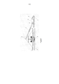
[0023] Além disso, um exemplo de aplicação da invenção é apresentado em conexão com as Figuras 1 a 3, que descrevem: • Figura 1: (vista frontal da aeronave): vista do sistema de inspeção não intrusiva no modo de digitalização; • Figura 2: (ver lado da aeronave): vista do sistema de inspeção não intrusiva no modo de digitalização, em outra variante de execução; • Figura 3: vista em perspectiva do sistema de inspeção não intrusiva, de acordo com a invenção, colocado dentro da zona de exclusão;[0023] Furthermore, an example of application of the invention is presented in connection with Figures 1 to 3, which describe: • Figure 1: (front view of the aircraft): view of the non-intrusive inspection system in scanning mode; • Figure 2: (see aircraft side): view of the non-intrusive inspection system in scanning mode, in another execution variant; • Figure 3: perspective view of the non-intrusive inspection system, according to the invention, placed inside the exclusion zone;
[0024] O sistema de inspeção não intrusiva, de acordo com a invenção, é um conjunto de digitalização não intrusivo móvel, instalado em um chassi do veículo 1 com baixa peso total, em que há um chassis suplementar, referido a partir deste ponto como uma superestrutura 2, que tem uma lança telescópica 3 montada em uma junta de dois graus 4, a dita junta detendo na sua extremidade a fonte de radiação penetrante 5. A lança telescópica 3 é feita de aço e metais leves e dobra da direção da cabine do motorista 6 em direção à aeronave digitalizada.[0024] The non-intrusive inspection system, according to the invention, is a mobile non-intrusive scanning assembly, installed on a vehicle chassis 1 with low total weight, in which there is a supplementary chassis, referred to from this point on as a superstructure 2, which has a telescopic boom 3 mounted on a two-degree joint 4, said joint holding at its end the source of penetrating radiation 5. The telescopic boom 3 is made of steel and light metals and bends the direction of the cabin from driver 6 towards the scanned aircraft.
[0025] O detector de linha 7 tem uma forma modular e será descarregado a partir do chassis 1 em módulos separados e será montado e fixado na pista, no interior da área de exclusão ‘a’. O dispositivo de puxar 8 também é descarregado a partir do chassis e preparado para ser ligado ao trem de pouso da aeronave, de modo que ele pode rebocar a referida aeronave através do portal de digitalização.[0025] Line detector 7 has a modular form and will be unloaded from chassis 1 in separate modules and will be mounted and fixed on the runway, inside the exclusion area 'a'. The pulling device 8 is also unloaded from the chassis and prepared to be connected to the aircraft's landing gear, so that it can tow said aircraft through the scanning portal.
[0026] Porque a área de digitalização das aeronaves deve ser ativamente protegida contra a radiação involuntária dos possíveis intrusos, um subsistema de proteção de perímetro 9 foi previsto, que determina uma zona de exclusão retangular ‘a’.[0026] Because the scanning area of aircraft must be actively shielded against involuntary radiation from would-be intruders, a perimeter protection subsystem 9 was envisaged, which determines a rectangular exclusion zone 'a'.
[0027] Um subsistema de gerenciamento de computador 10 comanda e controla remotamente todos os subsistemas de toda a assembléia: direção, velocidade do motor, bem como a posição do dispositivo de puxar na área de exclusão, bem como os outros periféricos ligados acordo com a invenção, se comunicando com eles através de uma LAN sem fio.[0027] A
[0028] Todos os componentes físicos do subsistema de gerenciamento de computador 10, assim como a estação de trabalho do operador, são instalados em um centro de controle móvel 11, que durante o transporte é rebocado pelo chassis 1, e durante o processo de digitalização está localizado fora da área de exclusão ‘a’.[0028] All physical components of the
[0029] A unidade de digitalização móvel, de acordo com a invenção, tem dois modos de apresentação física: modo de digitalização e modo de transporte. A conversão de um modo para outro é realizada por operar cilindros hidráulicos, cilindros estes que reconfiguram a posição da lança telescópica 3.[0029] The mobile scanning unit according to the invention has two physical presentation modes: scanning mode and transport mode. Conversion from one mode to another is performed by operating hydraulic cylinders, which cylinders reconfigure the position of the telescopic boom 3.
[0030] No modo de transporte, a lança telescópica 3 é fechada e dobrada ao longo do chassis 1, a fim de garantir o cumprimento dos limites dimensionais legais de transporte em vias públicas e também para distribuir uma boa repartição de peso em cada roda. Os componentes de sistemas de digitalização: a linha de detector 7 e o dispositivo de puxar 8 são carregados no chassis 1.[0030] In transport mode, the telescopic boom 3 is closed and folded along the chassis 1, in order to ensure compliance with the legal dimensional limits for transport on public roads and also to distribute a good distribution of weight on each wheel. Components of scanning systems: detector line 7 and pull device 8 are loaded in chassis 1.
[0031] No modo de digitalização, a linha de detector 7 é colocada na pista, e o dispositivo de puxar 8 está ligado ao trem de pouso da aeronave, que aguarda a digitalização. A lança telescópica 3 executa um movimento de rotação a partir da cabine do condutor, formando um ângulo de dimensão variável com o chassis plano 1, ângulo este que é determinado usando dimensões totais da aeronave digitalizada, a dita lança em seguida, executando um movimento de extensão a um tamanho pré-definido e finalmente, executando um movimento de rotação a partir do eixo transversal da estrutura 1, de modo que a fonte de radiação, que está localizado na extremidade da lança, esteja alinhada com a linha de detector. Depois que o sistema foi instalado, o processo de digitalização pode começar por iniciar um comando para o dispositivo de puxar 8, que está ligado ao trem de pouso da aeronave, aeronave esta que é rebocada por meio do portal da radiação, portal este que consiste na linha de detector 7 a qual é colocada sobre a pista, e da fonte de radiação penetrante 5, fonte esta que está localizada na extremidade da lança telescópica, lança esta fixada na unidade móvel de digitalização.[0031] In scan mode, detector line 7 is placed on the runway, and pull device 8 is attached to the aircraft's landing gear, which is waiting for scanning. The telescopic boom 3 performs a rotation movement from the driver's cabin, forming an angle of variable dimension with the flat chassis 1, which angle is determined using the total dimensions of the digitized aircraft, said boom then performing a movement of extension to a predefined size and finally, performing a rotational movement from the transverse axis of the structure 1, so that the radiation source, which is located at the end of the lance, is aligned with the detector line. After the system has been installed, the scanning process can begin by initiating a command to the pull device 8, which is connected to the aircraft's landing gear, which aircraft is towed through the radiation portal, which portal consists of in the detector line 7 which is placed on the track, and in the penetrating radiation source 5, which source is located at the end of the telescopic boom, the boom is fixed to the mobile digitizing unit.
[0032] O processo de digitalização pode ser interrompido automaticamente quando a aeronave passar completamente sobre a área de detector localizada na pista, quando intrusos violarem a área de exclusão, quando um sensor transmitir uma mensagem, sinalizando que a aeronave está fora de sua "trajetória pré-definida” ao passar sobre a linha de detector e quando a velocidade da aeronave flutua fora dos limites pré-definidos, limites estes que o sistema não pode gerir. Durante esta fase a imagem resultante da aeronave inspecionada é exibida na tela do operador e uma pasta com um ID único é criado e arquivado, pasta esta que contém a imagem digitalizada da aeronave e uma imagem fotográfica da aeronave. Quando a fase de digitalização estiver concluída, a fonte de radiação 5 é interrompida automaticamente, o subsistema de proteção de perímetro da área de exclusão ‘a’ é desativado, o dispositivo de puxar 8 se desprende da aeronave, após o que a referida aeronave pode sair da área de exclusão ‘a’, e o ciclo de digitalização pode ser retomado.[0032] The scanning process can be stopped automatically when the aircraft completely passes over the detector area located on the runway, when intruders violate the exclusion area, when a sensor transmits a message, signaling that the aircraft is out of its "trajectory" preset” when passing over the detector line and when the aircraft speed fluctuates outside the pre-defined limits, limits which the system cannot manage. During this phase the resulting image of the inspected aircraft is displayed on the operator's screen and a folder with a unique ID is created and archived, which folder contains the scanned image of the aircraft and a photographic image of the aircraft. When the scanning phase is complete, radiation source 5 is automatically stopped, the perimeter protection subsystem from the exclusion area 'a' is deactivated, the pulling device 8 detaches from the aircraft, after which said aircraft can leave the exclusion area 'a' , and the scanning cycle can be resumed.
[0033] Numa outra variante de execução, a unidade de digitalização móvel é colocada em frente da aeronave, a lança telescópica 3 é estendida ao longo do comprimento da aeronave e a linha do detector 7, que tem um determinado comprimento de modo a ser enquadrada pelo trem de pouso da aeronave, é rebocada pelo dispositivo de puxar 8, a partir da cauda da aeronave em direção nariz da aeronave, de forma sincronizada e, simultaneamente, com o movimento de retração da lança telescópica, sendo assim obtida uma imagem radiografada longitudinal ao corpo da aeronave.[0033] In another embodiment variant, the mobile scanning unit is placed in front of the aircraft, the telescopic boom 3 is extended along the length of the aircraft and the detector line 7, which has a certain length in order to be framed by the aircraft's landing gear, it is towed by the pulling device 8, from the aircraft's tail towards the aircraft's nose, synchronously and simultaneously with the retraction movement of the telescopic boom, thus obtaining a longitudinal radiographed image to the aircraft body.
[0034] O centro de controle móvel 11 é colocado fora da área de exclusão ‘a’, área esta que é delimitada pelo subsistema de proteção de perímetro 9.[0034] The
[0035] O chassis 1 tem de ser homologado de acordo com as normas internacionais em vigor, para o transporte em vias públicas com uma autorização especial. O chassis 1 é fornecido com um chassi de aço complementar, a superestrutura 2, que contém todos os componentes da unidade de digitalização móvel: os anexos do sistema hidráulico, o tanque de óleo, distribuidores, circuitos de segurança e controle, armários de circuitos elétricos e eletrônicos. Algumas dessas peças não são marcadas nos desenhos, uma vez que elas são bem conhecidas.[0035] Chassis 1 must be approved in accordance with current international standards for transport on public roads with a special permit. Chassis 1 is supplied with a complementary steel chassis, superstructure 2, which contains all the components of the mobile scanning unit: the hydraulic system attachments, the oil tank, distributors, safety and control circuits, electrical circuit cabinets and electronics. Some of these parts are not marked on the drawings as they are well known.
[0036] A fonte de radiação penetrante 5 é fixada na extremidade superior da lança telescópica 3, de tal modo que o feixe de radiação é colimado na linha de detectores 7 situado na pista, com o propósito de transformar a radiação penetrante percebida em sinais elétricos que são mais processados e transformados em imagens radiográficas da aeronave digitalizada. Portanto, se um gerador de Raios-X for utilizado, em seguida, detectores de híbridos com cristais de cintilação e os fotodiodos ou detectores monolíticos de carga acoplados com circuitos serão utilizados. No caso de uma fonte de radiação gama, serão utilizados detectores híbridos com cristais de cintilação juntamente com tubos fotomultiplicadores. O detector de alinhamento pode ser feito, dependendo da fonte de radiação escolhida e a construção dos detectores em uma fileira, duas fileiras ou em uma matriz de dimensão variável.[0036] The source of penetrating radiation 5 is fixed to the upper end of the telescopic boom 3, in such a way that the radiation beam is collimated on the line of detectors 7 located on the track, with the purpose of transforming the penetrating radiation perceived into electrical signals that are further processed and transformed into radiographic images of the digitized aircraft. Therefore, if an X-ray generator is used, then hybrid detectors with scintillation crystals and photodiodes or monolithic charge detectors coupled with circuits will be used. In the case of a gamma radiation source, hybrid detectors with scintillation crystals will be used together with photomultiplier tubes. The alignment detector can be made depending on the chosen radiation source and the construction of the detectors in one row, two rows or in a variable dimension array.
[0037] O subsistema de proteção de perímetro 9 da area de exclusão ‘a’ é um subsistema de proteção radiológica ativo que se aplica diretamente à fonte de radiação penetrante 5, de modo que a fonte 5 é desligada automaticamente quando intrusos violam a área de exclusão ‘a’, a fim de protegê-los contra vazamentos de radiação acidental. Os sensores ativos que compõem o subsistema de proteção de perímetro são colocados em pares, nas extremidades da zona de exclusão ‘a’, orientados a 90 graus um do outro, criando uma cortina virtual, que define uma área retangular, cujas dimensões dependem dos regulamentos atuais de cada país onde o processo de digitalização ocorre. Esses sensores estão permanentemente ligados, através do rádio, ao centro de controle móvel 11, para o qual eles enviam um sinal de alarme caso intrusos violem a área, o referido sinal desliga automaticamente a fonte 5 e ativa um texto, mensagem vocal e gráfica na interface gráfica do aplicativo de software do operador, do lado indicando que foi violado. O subsistema foi projetado para funcionar em difíceis condições meteorológicas como chuva, neve, vento, temperaturas extremas, etc. A proteção de perímetro é desativada para que ele permita a entrada / saída da área de exclusão.[0037] Exclusion area 'a' perimeter protection subsystem 9 is an active radiation protection subsystem that applies directly to penetrating radiation source 5, so that source 5 is automatically turned off when intruders breach the penetrating radiation area. 'a' exclusion, in order to protect them from accidental radiation leaks. The active sensors that make up the perimeter protection subsystem are placed in pairs, at the ends of the exclusion zone 'a', oriented at 90 degrees from each other, creating a virtual curtain, which defines a rectangular area, whose dimensions depend on regulations. information for each country where the digitization process takes place. These sensors are permanently linked, through the radio, to the
[0038] O centro de controle móvel 11 opera todos os componentes e os periféricos que compõem o sistema de digitalização móvel, garantindo a automação dos processos.[0038]
Claims (5)
Applications Claiming Priority (3)
| Application Number | Priority Date | Filing Date | Title |
|---|---|---|---|
| ROA201200443A RO127988B1 (en) | 2012-06-18 | 2012-06-18 | Method and system for non-intrusive inspection of aircrafts |
| ROA201200443 | 2012-06-18 | ||
| RO2014081327 | 2014-05-30 |
Publications (2)
| Publication Number | Publication Date |
|---|---|
| BR112014031727A2 BR112014031727A2 (en) | 2017-06-27 |
| BR112014031727B1 true BR112014031727B1 (en) | 2022-06-28 |
Family
ID=47220956
Family Applications (1)
| Application Number | Title | Priority Date | Filing Date |
|---|---|---|---|
| BR112014031727-5A BR112014031727B1 (en) | 2012-06-18 | 2012-12-06 | METHOD AND SYSTEM OF NON-INTRUSIVE AIRCRAFT INSPECTION |
Country Status (20)
| Country | Link |
|---|---|
| US (1) | US9352851B2 (en) |
| EP (1) | EP2862010B1 (en) |
| JP (1) | JP6099738B2 (en) |
| KR (1) | KR101955066B1 (en) |
| AP (1) | AP2015008218A0 (en) |
| AU (1) | AU2012394983B2 (en) |
| BR (1) | BR112014031727B1 (en) |
| CA (1) | CA2877269C (en) |
| EA (1) | EA030347B1 (en) |
| ES (1) | ES2724804T3 (en) |
| IL (1) | IL236331A0 (en) |
| IN (1) | IN2015DN00313A (en) |
| MA (1) | MA37718B1 (en) |
| MX (1) | MX344207B (en) |
| MY (1) | MY172969A (en) |
| PL (1) | PL2862010T3 (en) |
| RO (1) | RO127988B1 (en) |
| TR (1) | TR201906435T4 (en) |
| WO (1) | WO2014081327A2 (en) |
| ZA (1) | ZA201500331B (en) |
Families Citing this family (11)
| Publication number | Priority date | Publication date | Assignee | Title |
|---|---|---|---|---|
| WO2013103933A1 (en) * | 2012-01-06 | 2013-07-11 | Aerobotics, Inc. | Novel systems and methods that facilitate underside inspection of crafts |
| RO127852B1 (en) * | 2012-05-21 | 2019-03-29 | Mb Telecom Ltd Srl | Method and system for non-intrusive inspection of cargo type objects: motor vehicles, containers, train cars |
| CN103529480B (en) * | 2013-10-12 | 2017-02-01 | 清华大学 | System and method for examining aircraft |
| RO130582B1 (en) * | 2014-01-23 | 2021-12-30 | Mb Telecom Ltd. S.R.L. | System and method for complete and non-intrusive inspection of aircrafts |
| FR3035510B1 (en) * | 2015-04-21 | 2018-10-26 | Airbus Group Sas | ACOUSTICAL MEANS FOR DETECTION, LOCATION AND AUTOMATIC EVALUATION OF IMPACTS SUBJECT TO A STRUCTURE |
| CN106005471A (en) * | 2016-05-31 | 2016-10-12 | 中国航空工业集团公司西安飞机设计研究所 | Aircraft attitude control method and device for full-aircraft drop test for ship-borne early warning aircraft |
| GB2558238A (en) * | 2016-12-22 | 2018-07-11 | Smiths Heimann Sas | Method and apparatus |
| US11203445B2 (en) * | 2018-12-11 | 2021-12-21 | The Boeing Company | Data- and model-driven inspection of autonomous aircraft using an unmanned aerial vehicle |
| CN112363154B (en) * | 2020-10-14 | 2023-06-20 | 中国航天科工集团第二研究院 | Detection and identification system and method based on computed tomography mode |
| CN113044235B (en) * | 2021-04-14 | 2022-06-24 | 中国航空规划设计研究总院有限公司 | Automatic surface treatment system for airplane and using method thereof |
| CN116986013B (en) * | 2023-09-27 | 2023-12-15 | 中国飞机强度研究所 | Method and equipment for airplane landing gear sliding cable-passing impact test |
Family Cites Families (13)
| Publication number | Priority date | Publication date | Assignee | Title |
|---|---|---|---|---|
| US5237598A (en) * | 1992-04-24 | 1993-08-17 | Albert Richard D | Multiple image scanning X-ray method and apparatus |
| JP3576592B2 (en) * | 1994-05-06 | 2004-10-13 | 日本飛行機株式会社 | Transfer device |
| US5763886A (en) * | 1996-08-07 | 1998-06-09 | Northrop Grumman Corporation | Two-dimensional imaging backscatter probe |
| US6378387B1 (en) * | 2000-08-25 | 2002-04-30 | Aerobotics, Inc. | Non-destructive inspection, testing and evaluation system for intact aircraft and components and method therefore |
| US6614872B2 (en) * | 2001-01-26 | 2003-09-02 | General Electric Company | Method and apparatus for localized digital radiographic inspection |
| US6618465B2 (en) * | 2001-11-12 | 2003-09-09 | General Electric Company | X-ray shielding system and shielded digital radiographic inspection system and method |
| US6937692B2 (en) * | 2003-06-06 | 2005-08-30 | Varian Medical Systems Technologies, Inc. | Vehicle mounted inspection systems and methods |
| US6928141B2 (en) * | 2003-06-20 | 2005-08-09 | Rapiscan, Inc. | Relocatable X-ray imaging system and method for inspecting commercial vehicles and cargo containers |
| US7423273B2 (en) * | 2004-03-01 | 2008-09-09 | Varian Medical Systems Technologies, Inc. | Object examination by delayed neutrons |
| RO121293B1 (en) * | 2004-09-30 | 2007-02-28 | Mb Telecom Ltd. - S.R.L. | Non-intrusive control system and method |
| US7732772B1 (en) * | 2007-08-29 | 2010-06-08 | Raytheon Company | System and method for detecting explosive materials |
| EP2494340B1 (en) * | 2009-10-29 | 2020-03-11 | Rapiscan Systems, Inc. | Mobile aircraft inspection system |
| KR20140031163A (en) * | 2010-09-29 | 2014-03-12 | 에어로보틱스, 인크. | Novel systems and methods for non-destructive inspection of airplanes |
-
2012
- 2012-06-18 RO ROA201200443A patent/RO127988B1/en unknown
- 2012-12-06 MY MYPI2014703852A patent/MY172969A/en unknown
- 2012-12-06 AP AP2015008218A patent/AP2015008218A0/en unknown
- 2012-12-06 ES ES12886908T patent/ES2724804T3/en active Active
- 2012-12-06 MX MX2014015633A patent/MX344207B/en active IP Right Grant
- 2012-12-06 MA MA37718A patent/MA37718B1/en unknown
- 2012-12-06 AU AU2012394983A patent/AU2012394983B2/en active Active
- 2012-12-06 KR KR1020157001191A patent/KR101955066B1/en active IP Right Grant
- 2012-12-06 WO PCT/RO2012/000030 patent/WO2014081327A2/en active Application Filing
- 2012-12-06 EP EP12886908.8A patent/EP2862010B1/en active Active
- 2012-12-06 TR TR2019/06435T patent/TR201906435T4/en unknown
- 2012-12-06 IN IN313DEN2015 patent/IN2015DN00313A/en unknown
- 2012-12-06 BR BR112014031727-5A patent/BR112014031727B1/en active IP Right Grant
- 2012-12-06 US US14/408,743 patent/US9352851B2/en active Active
- 2012-12-06 JP JP2015518362A patent/JP6099738B2/en active Active
- 2012-12-06 CA CA2877269A patent/CA2877269C/en active Active
- 2012-12-06 EA EA201492293A patent/EA030347B1/en not_active IP Right Cessation
- 2012-12-06 PL PL12886908T patent/PL2862010T3/en unknown
-
2014
- 2014-12-17 IL IL236331A patent/IL236331A0/en unknown
-
2015
- 2015-01-16 ZA ZA2015/00331A patent/ZA201500331B/en unknown
Also Published As
| Publication number | Publication date |
|---|---|
| BR112014031727A2 (en) | 2017-06-27 |
| MX344207B (en) | 2016-12-08 |
| US20150197349A1 (en) | 2015-07-16 |
| JP2015526703A (en) | 2015-09-10 |
| AP2015008218A0 (en) | 2015-01-31 |
| EA201492293A1 (en) | 2015-03-31 |
| AU2012394983B2 (en) | 2017-02-23 |
| EA030347B1 (en) | 2018-07-31 |
| KR101955066B1 (en) | 2019-03-06 |
| ZA201500331B (en) | 2016-02-24 |
| MX2014015633A (en) | 2015-10-29 |
| MA20150080A1 (en) | 2015-02-27 |
| US9352851B2 (en) | 2016-05-31 |
| ES2724804T3 (en) | 2019-09-16 |
| CA2877269C (en) | 2018-06-12 |
| KR20150037839A (en) | 2015-04-08 |
| MA37718B1 (en) | 2016-02-29 |
| TR201906435T4 (en) | 2019-05-21 |
| NZ703133A (en) | 2016-07-29 |
| JP6099738B2 (en) | 2017-03-22 |
| MY172969A (en) | 2019-12-16 |
| EP2862010B1 (en) | 2019-02-13 |
| WO2014081327A3 (en) | 2014-08-21 |
| IN2015DN00313A (en) | 2015-06-12 |
| RO127988B1 (en) | 2019-12-30 |
| RO127988A0 (en) | 2012-11-29 |
| WO2014081327A2 (en) | 2014-05-30 |
| AU2012394983A1 (en) | 2015-01-22 |
| IL236331A0 (en) | 2015-02-26 |
| CA2877269A1 (en) | 2014-05-30 |
| EP2862010A2 (en) | 2015-04-22 |
| PL2862010T3 (en) | 2019-07-31 |
Similar Documents
| Publication | Publication Date | Title |
|---|---|---|
| BR112014031727B1 (en) | METHOD AND SYSTEM OF NON-INTRUSIVE AIRCRAFT INSPECTION | |
| RU2610930C2 (en) | Road and railway transport non-intrusive inspection method and system | |
| CN105445294B (en) | Vehicular checks system | |
| EP3097439B1 (en) | System and method for nonintrusive complete aircraft inspection | |
| KR102198036B1 (en) | Security inspection system and method | |
| KR102236745B1 (en) | Luggage cart | |
| NZ703133B2 (en) | Nonintrusive inspection method and system of aircrafts | |
| RO134711A0 (en) | Variable-geometry dual-view scanning system and method for aircrafts |
Legal Events
| Date | Code | Title | Description |
|---|---|---|---|
| B06F | Objections, documents and/or translations needed after an examination request according [chapter 6.6 patent gazette] | ||
| B06U | Preliminary requirement: requests with searches performed by other patent offices: procedure suspended [chapter 6.21 patent gazette] | ||
| B06A | Patent application procedure suspended [chapter 6.1 patent gazette] | ||
| B09A | Decision: intention to grant [chapter 9.1 patent gazette] | ||
| B16A | Patent or certificate of addition of invention granted [chapter 16.1 patent gazette] |
Free format text: PRAZO DE VALIDADE: 20 (VINTE) ANOS CONTADOS A PARTIR DE 06/12/2012, OBSERVADAS AS CONDICOES LEGAIS |