BR112014030223B1 - DERIVATION SYSTEM FOR AERIAL POWER LINES, AND, METHOD FOR OPERATING THE DERIVATION OF A SECTION OF AN ELECTRICAL LINE WITH AERIAL END - Google Patents
DERIVATION SYSTEM FOR AERIAL POWER LINES, AND, METHOD FOR OPERATING THE DERIVATION OF A SECTION OF AN ELECTRICAL LINE WITH AERIAL END Download PDFInfo
- Publication number
- BR112014030223B1 BR112014030223B1 BR112014030223-5A BR112014030223A BR112014030223B1 BR 112014030223 B1 BR112014030223 B1 BR 112014030223B1 BR 112014030223 A BR112014030223 A BR 112014030223A BR 112014030223 B1 BR112014030223 B1 BR 112014030223B1
- Authority
- BR
- Brazil
- Prior art keywords
- support structure
- bypass system
- fact
- support structures
- external termination
- Prior art date
Links
Images


Classifications
-
- H—ELECTRICITY
- H02—GENERATION; CONVERSION OR DISTRIBUTION OF ELECTRIC POWER
- H02B—BOARDS, SUBSTATIONS OR SWITCHING ARRANGEMENTS FOR THE SUPPLY OR DISTRIBUTION OF ELECTRIC POWER
- H02B1/00—Frameworks, boards, panels, desks, casings; Details of substations or switching arrangements
- H02B1/26—Casings; Parts thereof or accessories therefor
- H02B1/52—Mobile units, e.g. for work sites
-
- H—ELECTRICITY
- H02—GENERATION; CONVERSION OR DISTRIBUTION OF ELECTRIC POWER
- H02G—INSTALLATION OF ELECTRIC CABLES OR LINES, OR OF COMBINED OPTICAL AND ELECTRIC CABLES OR LINES
- H02G1/00—Methods or apparatus specially adapted for installing, maintaining, repairing or dismantling electric cables or lines
- H02G1/02—Methods or apparatus specially adapted for installing, maintaining, repairing or dismantling electric cables or lines for overhead lines or cables
- H02G1/04—Methods or apparatus specially adapted for installing, maintaining, repairing or dismantling electric cables or lines for overhead lines or cables for mounting or stretching
Abstract
sistema de derivação para linhas de potência aéreas, e, método para operar a derivação de uma seção de uma linha elétrica possuindo uma extremidade aérea um sistema de derivação para linhas de potência aéreas compreende estruturas de suporte móveis entre uma posição de espera e uma posição de operação, atuadores para mover as estruturas de suporte entre a posição de espera e a posição ativa, pelo menos uma terminação externa ligada às estruturas de suporte para ser movida entre a posição de espera e a posição de operação das estruturas de suporte.bypass system for overhead power lines, and, method to operate the bypass of a section of an electric line having an overhead end a bypass system for overhead power lines comprises movable support structures between a standby position and a actuators, actuators for moving the support structures between the standby position and the active position, at least one external termination connected to the support structures to be moved between the standby position and the operating position of the support structures.
Description
[001] A presente invenção refere-se a um sistema de derivação para linhas de transmissão aéreas.[001] The present invention relates to a bypass system for overhead transmission lines.
[002] Uma linha de transmissão aérea é uma linha de transmissão de potência elétrica aérea, compreendendo um ou mais condutores elétricos nus, suspensos por torres ou postes. Uma vez que a maior parte do isolamento é provido pelo ar, linhas de transmissão aéreas são geralmente um método conveniente de transmissão para grandes quantidades de energia elétrica e são, portanto, usadas principalmente para conduzir corrente de alta tensão (HV) (tipicamente mais alta que 30-35 kV).As linhas de transmissão aéreas necessitam torres para serem suportadas e isoladores para isolar a estrutura das torres (tipicamente torres de aço do tipo grade) de cada condutor da linha de transmissão de energia elétrica aérea; as extremidades do cabo isolado são conectadas às linhas de transmissão aéreas nas estações terminais relevantes ou subestações, por meio de componentes, chamados terminações, adequados para prover a transição requerida a partir do condutor nu da linha aérea, isolada pelo ar, para um cabo, apresentando um condutor coberto por uma camada de isolamento e uma blindagem elétrica aterrada.[002] An overhead transmission line is an overhead electrical power transmission line, comprising one or more bare electrical conductors, suspended by towers or poles. Since most of the insulation is provided by air, overhead transmission lines are generally a convenient method of transmission for large amounts of electrical energy and are therefore used primarily to conduct high voltage (HV) currents (typically higher than 30-35 kV). Overhead transmission lines require towers to be supported and insulators to isolate the tower structure (typically grid-type steel towers) from each conductor of the overhead power transmission line; the ends of the insulated cable are connected to the overhead transmission lines at the relevant terminal stations or substations, by means of components, called terminations, suitable to provide the required transition from the bare conductor of the overhead line, insulated by air, to a cable, featuring a conductor covered by an insulation layer and a grounded electrical shield.
[003] Linhas de transmissão aéreas compreendem tipicamente subestações como parte do sistema de geração, transmissão e distribuição elétrica. Por exemplo, subestações transformam tensão de alta para baixa, ou o inverso, conectam as linhas de transmissão aéreas a linhas cabeadas ou executam quaisquer de diversas outras funções da rede elétrica.[003] Overhead transmission lines typically comprise substations as part of the electrical generation, transmission and distribution system. For example, substations transform voltage from high to low, or the other way around, connect overhead transmission lines to wired lines or perform any of several other network functions.
[004] Manutenção ordinária e extraordinária necessita ser efetuada nas linhas de transmissão aéreas, especialmente nas subestações, por exemplo, quando ocorre remodelação e reconstrução da torre e das linhas de transmissão aéreas; quando é requerida restauração ou expansão nas subestações; quando transformadores de potência, disjuntores, chaves comutadoras, derivações ou outros componentes de uma subestação devem ser substituídos.[004] Ordinary and extraordinary maintenance needs to be carried out on overhead transmission lines, especially at substations, for example, when remodeling and reconstruction of the tower and overhead transmission lines occurs; when restoration or expansion in substations is required; when power transformers, circuit breakers, switchgear, taps or other components of a substation must be replaced.
[005] Tais operações são efetuadas desconectando, da linha de transmissão elétrica, todos os componentes envolvidos na atividade de manutenção. Sistemas de derivação temporários que conectam pontos de entrada e saída dentro das subestações são usados, no sentido de garantir a continuidade do suprimento de potência elétrica aos usuários durante o período de manutenção. Tipicamente, pelo menos uma das extremidades do sistema de derivação ou ambas, é conectada à linha de transmissão aérea.[005] Such operations are carried out by disconnecting, from the electrical transmission line, all components involved in the maintenance activity. Temporary bypass systems that connect entry and exit points inside the substations are used, in order to guarantee the continuity of the electric power supply to the users during the maintenance period. Typically, at least one end of the bypass system or both, is connected to the overhead transmission line.
[006] Um exemplo de sistema de derivação para linhas de transmissão aéreas é descrito em HVSBL, Janeiro de 2006, por Silec Cable (www.sileccable.com/Portals/france/pdf/en/2151 HVSBL.pdf).[006] An example of a bypass system for overhead transmission lines is described in HVSBL, January 2006, by Silec Cable (www.sileccable.com/Portals/france/pdf/en/2151 HVSBL.pdf).
[007] De acordo com esta publicação, um sistema de Enlace de Reserva de Alta Tensão (HVSBL) trifásico é composto de três extensões de cabos equipados com duas terminações sintéticas pré montadas em fábrica; três tambores dedicados permitindo armazenagem, transporte e desenrolamento e re-enrolamento das extensões equipadas com suas terminações; seis estruturas metálicas para suportar as terminações durante o uso (opcional).[007] According to this publication, a three-phase High Voltage Reserve Link (HVSBL) system is made up of three cable extensions equipped with two synthetic terminals pre-assembled at the factory; three dedicated drums allowing storage, transport and unwinding and rewinding of the extensions equipped with their terminations; six metal structures to support the terminations during use (optional).
[008] Os sistemas de enlace ilustrados são condicionados em tambores metálicos dedicados ajustados para conter e proteger o cabo equipado com suas duas terminações. Um sistema de enlace trifásico pode compreender um único tambor de 2,6 m de diâmetro equipado com três compartimentos, permitindo instalar as três fases no mesmo tambor de um HVSBL de 90 kV de 20 m, até três tambores específicos de 4,7 m cada um, contendo uma fase de um HVSBL de 225 kV de 350 m. Geralmente, as terminações são instaladas em proteções (tubo ou subquadro) instaladas e afastadas no lado interno do tambor (para transporte).A extensão das terminação aumenta com a tensão e pode ser compreendida entre 1,8 m para 90 kV e 2,8 m para 225 kV. Os tambores fornecidos, equipamento de colocação e ferramentas de rotina são transportados por caminhão de um pátio de armazenagem para o local de instalação. Uma estrutura metálica suportando as terminações durante a operação pode ser uma estrutura metálica permitindo o suporte mecânico de uma terminação; cada terminação é erguida por um guindaste para ser posicionada no topo de uma respectiva estrutura metálica e acoplada mecanicamente a ela.[008] The illustrated link systems are conditioned in dedicated metal drums adjusted to contain and protect the cable equipped with its two terminations. A three-phase linkage system can comprise a single 2.6 m diameter drum equipped with three compartments, allowing the three phases to be installed on the same drum of a 20 m HVSBL 90 kV, up to three specific 4.7 m drums each one, containing a 225 kV 350 m HVSBL phase. Generally, the terminations are installed in guards (tube or subframe) installed and spaced on the inner side of the drum (for transport). The extension of the termination increases with the voltage and can be comprised between 1.8 m to 90 kV and 2.8 m to 225 kV. The supplied drums, placement equipment and routine tools are transported by truck from a storage yard to the installation site. A metallic structure supporting the terminations during operation can be a metallic structure allowing the mechanical support of a termination; each termination is lifted by a crane to be positioned on top of a respective metallic structure and mechanically coupled to it.
[009] Tipicamente, o procedimento de instalação de enlaces de derivação temporários para uma linha de potência trifásica compreende as seguintes etapas:
- - descarregar três tambores acoplados por mancal, de um caminhão, por meio de um guindaste;
- - desenrolar uma extensão de cabo de cada enlace de cada tambor e colocá-la no solo, no local de conexão da terminação externa desta;
- - prover o local de conexão de uma estrutura de suporte para cada terminação externa de cada enlace;
- - conectar cada terminação externa à linha de transmissão aérea e a outra extremidade do cabo a outra linha de potência.
- - unload three drums coupled per bearing, from a truck, by means of a crane;
- - unroll an extension of cable from each link of each drum and place it on the ground, at the connection point of the external termination of this;
- - provide the connection location of a support structure for each external termination of each link;
- - connect each external termination to the overhead transmission line and the other end of the cable to another power line.
[0010] Tal procedimento dispende uma quantidade substancial de tempo (por exemplo, muitas semanas de trabalho, especialmente no caso de terminação para tensão mais alta que 200 kV) e isto é crítico, especialmente no caso de uma falha de linha a ser restaurada.[0010] Such a procedure takes a substantial amount of time (for example, many weeks of work, especially in the case of termination for voltage higher than 200 kV) and this is critical, especially in the case of a line failure to be restored.
[0011] Devido à necessidade de manter ou reparar linhas de transmissão aéreas, derivar certas posições ou pontos de uma linha de transmissão de energia elétrica é usualmente uma operação mandatória para garantir o suprimento de energia elétrica aos usuários.[0011] Due to the need to maintain or repair overhead transmission lines, deriving certain positions or points from an electricity transmission line is usually a mandatory operation to guarantee the supply of electricity to users.
[0012] O Requerente observou que seria vantajoso ter tempo de operação curto para prover derivação em linhas de transmissão de energia elétrica.[0012] The Applicant noted that it would be advantageous to have a short operating time to provide a derivation in electric power transmission lines.
[0013] Em particular, o Requerente abordou o programa de prover um sistema de derivação para linhas de transmissão aéreas que requer tempo mais curto e pouco pessoal para ser instalado no campo, comparado aos convencionais.[0013] In particular, the Applicant addressed the program of providing a bypass system for overhead transmission lines that requires shorter and less staffed time to be installed in the field, compared to conventional ones.
[0014] O Requerente verificou os problemas acima mencionados podem ser resolvidos por um sistema de ligação de derivação para linhas elétricas de alta tensão AC, compreendendo, para cada fase, uma terminação externa, uma extensão de cabo e uma junção de cabo, pré montadas e transportáveis para o local de conexão com a linha de transmissão aérea.[0014] The Applicant has verified the problems mentioned above can be solved by a branch connection system for high voltage AC electric lines, comprising, for each phase, an external termination, a cable extension and a cable junction, pre-assembled and transportable to the place of connection with the overhead transmission line.
[0015] Em particular, o Requerente verificou que a instalação rápida de um sistema de ligação de derivação pode ser obtida arranjando uma terminação externa, uma extensão de cabo e uma junção de cabo sobre um aparelho de suporte, móvel de uma posição de repouso para uma posição de operação e atuando adicionalmente como uma estrutura de suporte para manter a terminação externa no modo de operação pelo tempo durante o qual a ligação de derivação é operada.[0015] In particular, the Applicant has verified that the quick installation of a bypass connection system can be obtained by arranging an external termination, a cable extension and a cable joint on a support device, movable from a resting position to an operating position and additionally acting as a support structure to maintain the external termination in the operating mode for the duration of which the branch connection is operated.
[0016] Em um aspecto, a presente invenção relaciona-se a um sistema de derivação para linhas de transmissão aéreas compreendendo
- - um invólucro;
- - uma estrutura de suporte no citado invólucro;
- - uma terminação externa ligada à estrutura de suporte, onde citada estrutura de suporte é móvel entre uma posição de espera e uma posição de operação da terminação externa;
- - um cabo elétrico, conectado eletricamente à terminação externa.
- - a wrapper;
- - a support structure in said enclosure;
- - an external termination connected to the support structure, where said support structure is movable between a waiting position and an operating position of the external termination;
- - an electrical cable, electrically connected to the external termination.
[0017] Em uma realização preferida, o invólucro da presente derivação é transportável. Em particular, um invólucro transportável pode ser arranjado sobre um veículo ou pode fazer parte de um veículo.[0017] In a preferred embodiment, the housing of the present derivation is transportable. In particular, a transportable casing can be arranged over a vehicle or it can be part of a vehicle.
[0018] Na posição de espera, a terminação externa está dentro do citado invólucro, de tal modo que o transporte pode ser habilitado com o volume reduzido e se estende pelo menos parcialmente para fora do citado invólucro na posição de operação da terminação externa.[0018] In the standby position, the external termination is within the said enclosure, in such a way that the transport can be enabled with the reduced volume and extends at least partially out of the said enclosure in the operating position of the external termination.
[0019] Preferivelmente, citado cabo elétrico é fixado à estrutura de suporte para ser movido integralmente com citada terminação externa, entre a posição de espera e a posição de operação da terminação externa.[0019] Preferably, said electrical cable is attached to the support structure to be moved integrally with said external termination, between the waiting position and the operating position of the external termination.
[0020] Preferivelmente, citada estrutura de suporte é rotativa dentro do invólucro em relação à um eixo de rotação, para se mover da posição de espera para a posição de operação.[0020] Preferably, said support structure is rotatable within the housing in relation to an axis of rotation, to move from the waiting position to the operating position.
[0021] Convenientemente, tipicamente para uso para uma linha elétrica trifásica, três estruturas de suporte são abrigadas no invólucro.[0021] Conveniently, typically for use for a three-phase power line, three support structures are housed in the enclosure.
[0022] Preferivelmente, pelo menos duas estruturas de suporte são espaçadas longitudinalmente dentro do invólucro.[0022] Preferably, at least two support structures are spaced longitudinally within the housing.
[0023] Preferivelmente, três estruturas de suporte são abrigadas dentro do invólucro e os eixos de rotação relevantes estão em um ângulo com cada outro no plano vertical.[0023] Preferably, three support structures are housed within the housing and the relevant axes of rotation are at an angle to each other in the vertical plane.
[0024] Em uma realização preferida, a estrutura de suporte compreende uma viga apresentando uma forma substancialmente curva, citada terminação externa sendo fixada mecanicamente a uma primeira extremidade da citada viga e citado cabo elétrico é fixado à citada viga. Preferivelmente, citada estrutura de suporte compreende diversos apoios apresentando as primeiras extremidades fixadas à citada viga e segundas extremidades convergindo para uma articulação formando o eixo de rotação da estrutura de suporte.[0024] In a preferred embodiment, the support structure comprises a beam having a substantially curved shape, said external termination being mechanically fixed to a first end of said beam and said electrical cable is fixed to said beam. Preferably, said support structure comprises several supports having the first ends fixed to said beam and second ends converging to a joint forming the axis of rotation of the support structure.
[0025] Preferivelmente, o sistema de derivação compreende uma estrutura de suporte central e duas estruturas de suporte lateral mantendo as terminações externas relevantes, arranjadas em lados opostos em relação à estrutura de suporte central, onde o eixo de rotação da estrutura de suporte central apresenta um assentamento substancialmente horizontal e os eixos de rotação das estruturas de suporte lateral são inclinados em relação ao eixo de rotação da estrutura de suporte central, pelo que a estrutura de suporte central é rotativa em um primeiro plano substancialmente vertical e as estruturas de suporte lateral são rotativas em respectivos segundo e terceiro planos, divergindo para cima.[0025] Preferably, the bypass system comprises a central support structure and two lateral support structures maintaining the relevant external terminations, arranged on opposite sides in relation to the central support structure, where the axis of rotation of the central support structure presents a substantially horizontal seat and the axes of rotation of the lateral support structures are inclined with respect to the axis of rotation of the central support structure, whereby the central support structure is rotatable in a substantially vertical foreground and the lateral support structures are rotating in respective second and third planes, diverging upwards.
[0026] Preferivelmente, uma junção de cabo pré fabricada é conectada à extremidade do cabo elétrico oposta à extremidade conectada à terminação externa.[0026] Preferably, a prefabricated cable joint is connected to the end of the electrical cable opposite the end connected to the external termination.
[0027] Vantajosamente, a junção de cabo provida na segunda extremidade do cabo elétrico é do tipo habilitando a rápida conexão à rede elétrica (conexão de encaixe).[0027] Advantageously, the cable junction provided on the second end of the electrical cable is of the type enabling quick connection to the electrical network (plug-in connection).
[0028] Preferivelmente, o invólucro mantém um atuador operacionalmente conectado à estrutura de suporte para causar o movimento desta entre citada posição de espera e citada posição de operação da terminação externa.[0028] Preferably, the enclosure maintains an actuator operationally connected to the support structure to cause its movement between the said waiting position and the operating position of the external termination.
[0029] Mais preferivelmente, citado atuador é um atuador linear, operando sobre um eixo não interceptando o eixo de rotação da estrutura de suporte.[0029] More preferably, said actuator is a linear actuator, operating on an axis not intercepting the axis of rotation of the support structure.
[0030] Em um segundo aspecto, a presente invenção relaciona-se a um método para operar uma derivação de uma seção de uma linha elétrica apresentando uma extremidade aérea, que compreende:
- - prever um sistema de derivação incluindo uma estrutura de suporte contida em um invólucro, com uma terminação externa conectada à estrutura de suporte e um cabo elétrico eletricamente conectado à citada terminação externa em uma extremidade desta;
- - dispor citado sistema de derivação na proximidade da citada seção de uma linha elétrica, enquanto a estrutura de suporte está em uma posição de espera;
- - mover citada estrutura de suporte em uma posição de operação da terminação externa;
- - conectar eletricamente citada terminação externa à citada extremidade aérea da seção de linha elétrica.
- - provide for a bypass system including a support structure contained in a housing, with an external termination connected to the support structure and an electrical cable electrically connected to the aforementioned external termination at one end thereof;
- - have said shunt system in the vicinity of the said section of an electric line, while the support structure is in a waiting position;
- - move said support structure in an operating position of the external termination;
- - electrically connect said external termination to the aforementioned aerial end of the power line section.
[0031] Preferivelmente, o método compreende adicionalmente prover uma junção de cabo pré fabricada fixada a uma extremidade do citado cabo elétrico, oposta à extremidade eletricamente conectada à citada terminação externa e conectando eletricamente citada junção pré fabricada a uma extremidade da citada seção de uma linha elétrica oposta à citada extremidade aérea.[0031] Preferably, the method further comprises providing a prefabricated cable junction attached to one end of said electrical cable, opposite the end electrically connected to said external termination and electrically connecting said prefabricated junction to one end of said section of a line opposite the aforementioned aerial end.
[0032] Dentro da presente descrição, o termo “transportável” significa projetado para ser transferido de um lugar, por exemplo, uma armazenagem remota, até o local de operação.[0032] Within the present description, the term "transportable" means designed to be transferred from a place, for example, remote storage, to the place of operation.
[0033] O termo “terminação externa”, conforme usado aqui, refere-se a um componente no qual uma extremidade de um cabo elétrico isolado é acomodada, apresentando um conector para conexão com uma linha elétrica aérea, conectada ao cabo condutor, e um isolamento e estrutura de blindagem adequados para prover isolamento entre conector e a terra.[0033] The term "external termination", as used here, refers to a component in which one end of an insulated electrical cable is accommodated, featuring a connector for connection to an overhead power line, connected to the conductor cable, and a insulation and shielding structure suitable to provide insulation between connector and ground.
[0034] Dentro da presente descrição, por “posição ativa” ou “posição de operação” é indicada uma posição na qual a terminação externa pode ser eletricamente conectada a uma linha de transmissão aérea. Nesta posição, a terminação é arranjada para operar na linha, de um ponto de vista mecânico e elétrico.[0034] Within the present description, by "active position" or "operating position" is indicated a position in which the external termination can be electrically connected to an overhead transmission line. In this position, the termination is arranged to operate on the line, from a mechanical and electrical point of view.
[0035] Dentro da presente descrição, por “posição de espera” é indicada uma posição na qual a terminação externa é abrigada e envelopada dentro do invólucro para proteção, armazenagem e transporte.[0035] Within the present description, by "waiting position" is indicated a position in which the external termination is housed and enveloped within the enclosure for protection, storage and transportation.
[0036] Dentro da presente descrição, como “cabo elétrico” é considerado um cabo elétrico isolado, a menos que especificado em contrário.[0036] Within the present description, as "electrical cable" is considered an insulated electrical cable, unless otherwise specified.
[0037] As estruturas de suporte permitem que as linhas de conexão elétrica do sistema de derivação como um todo e as terminações externas em particular, sejam facilmente e rapidamente colocadas em uma condição pronta para operação. Isto permite evitar a necessidade de executar um gerenciamento direto das terminações externas, o que requer meios de reboque e suporte para serem movidas e transportadas como partes independentes de uma ligação de derivação.[0037] The support structures allow the electrical connection lines of the branch system as a whole and the external terminations in particular, to be easily and quickly put into a condition ready for operation. This avoids the need to perform a direct management of the external terminations, which requires towing and support means to be moved and transported as independent parts of a bypass connection.
[0038] A estrutura de suporte permite que a terminação externa seja mantida em posição para a conexão elétrica, sem a necessidade de acessórios adicionais de montagem ou similares, conforme requerido pelos sistemas de derivação conhecidos.[0038] The support structure allows the external termination to be kept in position for the electrical connection, without the need for additional mounting accessories or the like, as required by known derivation systems.
[0039] Preferivelmente, o invólucro está associado a diversas rodas para transporte por estrada.[0039] Preferably, the casing is associated with several wheels for transport by road.
[0040] Mais preferivelmente, o invólucro é suportado em um reboque de caminhão.[0040] More preferably, the casing is supported on a truck trailer.
[0041] Preferivelmente, o invólucro compreende paredes laterais, uma parede superior e uma parede de base, citadas paredes formando um recipiente envolvendo a estrutura do suporte e a linha de conexão elétrica quando a estrutura de suporte está na posição de espera.[0041] Preferably, the enclosure comprises side walls, an upper wall and a base wall, said walls forming a container surrounding the support structure and the electrical connection line when the support structure is in the standby position.
[0042] Preferivelmente, pelo menos citada parede superior é pelo menos parcialmente removível para prover uma abertura superior no recipiente.[0042] Preferably, at least said upper wall is at least partially removable to provide an upper opening in the container.
[0043] Dentro da presente descrição o termo “horizontal” denota uma orientação espacial substancialmente paralela ao solo.[0043] Within the present description the term "horizontal" denotes a spatial orientation substantially parallel to the ground.
[0044] Preferivelmente, a estrutura de suporte central e a respectiva terminação externa assentam em um plano substancialmente vertical, o eixo de rotação da estrutura de suporte sendo perpendicular a tal plano vertical.[0044] Preferably, the central support structure and the respective external termination rest on a substantially vertical plane, the axis of rotation of the support structure being perpendicular to such vertical plane.
[0045] Dentro da presente descrição, o termo “vertical” denota uma orientação espacial substancialmente perpendicular ao solo.[0045] Within the present description, the term "vertical" denotes a spatial orientation substantially perpendicular to the ground.
[0046] Na realização preferida da invenção, as estruturas de suporte lateral e respectivas terminações externas assentam em planos inclinados em relação ao plano vertical, os eixos de rotação das estruturas de suporte lateral sendo perpendiculares ao respectivo plano inclinado.[0046] In the preferred embodiment of the invention, the lateral support structures and their external terminations lie on inclined planes with respect to the vertical plane, the axes of rotation of the lateral support structures being perpendicular to the respective inclined plane.
[0047] Para a finalidade da presente descrição e reivindicações anexas, exceto onde indicado em contrário, todos os números expressando valores, quantidades, percentuais e assim por diante, devem ser entendidos como sendo modificados em todas às situações pelo termo “cerca de”. Também, todas as faixas incluem os pontos máximo e mínimo descritos e incluem quaisquer faixas intermediárias, que podem ou não ser especificamente enumeradas aqui.[0047] For the purpose of the present description and appended claims, except where otherwise indicated, all numbers expressing values, quantities, percentages and so on, should be understood as being modified in all situations by the term "about". Also, all ranges include the maximum and minimum points described and include any intermediate ranges, which may or may not be specifically listed here.
[0048] A presente invenção será agora descrita mais plenamente a seguir, com referência aos desenhos que a acompanham.[0048] The present invention will now be described more fully below, with reference to the accompanying drawings.
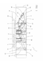
[0049] A Figura 1 é uma vista lateral esquemática de um sistema de derivação para linhas de potência aéreas, de acordo com uma realização da presente invenção, em uma posição de espera.[0049] Figure 1 is a schematic side view of a bypass system for overhead power lines, according to an embodiment of the present invention, in a standby position.
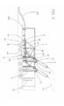
[0050] A Figura 2 é uma vista lateral esquemática do sistema de derivação para linhas de potência aéreas da Figura 1, em uma posição de operação.[0050] Figure 2 is a schematic side view of the bypass system for overhead power lines of Figure 1, in an operating position.
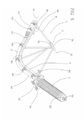
[0051] A Figura 3 é uma vista superior do sistema de derivação para linhas de potência aéreas da Figura 2.[0051] Figure 3 is a top view of the branch system for overhead power lines in Figure 2.
[0052] A Figura 4 é uma vista poste do sistema de derivação para linhas de potência aéreas da Figura 2.[0052] Figure 4 is a post view of the branch system for overhead power lines in Figure 2.
[0053] A Figura 5 é um detalhe da estrutura de suporte e da terminação e cabo fixado a ela.[0053] Figure 5 is a detail of the support structure and the termination and cable attached to it.
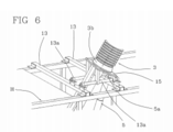
[0054] A Figura 6 é um detalhe de uma fase do movimento para localizar a terminação e estrutura de suporte em posição de operação.[0054] Figure 6 is a detail of a phase of the movement to locate the termination and support structure in the operating position.
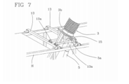
[0055] A Figura 7 é um detalhe mostrando a terminação e estrutura de suporte fixada na posição de operação.[0055] Figure 7 is a detail showing the termination and support structure fixed in the operating position.
[0056] Com referência às figuras anexas, o numeral de referência 1 denota globalmente um sistema de derivação para linhas de potência aéreas.[0056] With reference to the attached figures, reference numeral 1 globally denotes a bypass system for overhead power lines.
[0057] O sistema de derivação da invenção é adaptado para ser usado para derivar uma seção de uma linha elétrica onde pelo menos um ponto de derivação é aéreo. O sistema de derivação da invenção é preferivelmente usado em linhas de alta e muito alta tensão elétrica, onde, por alta tensão é indicada uma tensão na faixa entre 30 kV e 150 kV e por tensão muito alta é indicada uma tensão mais alta que 150 kV.[0057] The derivation system of the invention is adapted to be used to derive a section of an electric line where at least one derivation point is overhead. The derivation system of the invention is preferably used in high and very high electric voltage lines, where, for high voltage, a voltage in the range between 30 kV and 150 kV is indicated and for very high voltage, a voltage higher than 150 kV is indicated. .
[0058] O sistema de derivação 1 mostrado nas figuras é um exemplo para uso em linhas de tensão de 220 kV e subestações relevantes.[0058] The bypass system 1 shown in the figures is an example for use in 220 kV voltage lines and relevant substations.
[0059] O sistema de derivação compreende três estruturas de suporte 2, arranjadas dentro de um invólucro H, as quais são móveis entre uma posição de espera (mostrada na Figura 1) e uma posição ativa ou de operação (mostrada na Figura 2).[0059] The bypass system comprises three support structures 2, arranged within an H housing, which are movable between a standby position (shown in Figure 1) and an active or operating position (shown in Figure 2).
[0060] Uma linha de conexão elétrica 9, compreendendo um cabo elétrico 4 e uma terminação externa 3 é suportada por cada estrutura de suporte 2.[0060] An
[0061] Conforme mostrado na Figura 2, a terminação externa 3 é fixada, em sua extremidade do fundo 3b, a uma placa base 15 da estrutura de suporte 2 relevante e tem sua extremidade superior 3a pronta para ser eletricamente conectada à linha de potência aérea, via um condutor aéreo 3c, quando o sistema de derivação está na posição de operação.[0061] As shown in Figure 2, the
[0062] O cabo elétrico 4 tem sua primeira extremidade 4a eletricamente e mecanicamente conectada à terminação externa 3.A segunda extremidade 4b do cabo elétrico 4 está pronta para ser conectada a um cabo 100 (Figuras 2 e 3), por exemplo, um cabo elétrico destinado a ser eletricamente conectado ao segundo ponto de derivação (como será melhor explicado a seguir).[0062] The electrical cable 4 has its
[0063] O cabo elétrico 4 é fixado à estrutura de suporte 2 relevante para ser movido integralmente com a terminação externa 3, entre a posição de espera e a posição de operação do sistema de derivação 1.[0063] The electrical cable 4 is attached to the relevant support structure 2 to be moved integrally with the
[0064] O sistema de derivação 1 compreende adicionalmente atuadores 5, ativos nas estruturas de suporte 2 relevantes para mover as mesmas entre a posição de espera e a posição ativa.[0064] The bypass system 1 additionally comprises
[0065] Os atuadores 5 são preferivelmente atuadores lineares, tais como conectores hidráulicos, conectores de parafuso ou similares. Alternativamente, outros atuadores podem ser usados, tais como atuadores do tipo engrenagem ou similares.[0065]
[0066] Em uma alternativa adicional, os atuadores podem não estar presentes e, em tal caso, as estruturas de suporte 2 são movidas na posição de operação por meio de um aparelho externo, tal como um guindaste ou similar.[0066] In an additional alternative, the actuators may not be present and, in such a case, the support structures 2 are moved in the operating position by means of an external device, such as a crane or similar.
[0067] As estruturas de suporte 2 compreendem uma viga 6 apresentando uma forma substancialmente curva. Em particular, a viga 6 possui duas porções de extremidade substancialmente retilíneas 6a, 6b, superior e inferior respectivamente, unidas uma à outra por uma porção curva 6c.Como na Figura 2, as duas porções retilíneas 6a, 6b apresentam eixos a1 e a2 que estão em um ângulo α um com o outro. O ângulo α varia entre 15o e 80o, preferivelmente entre 30o e 60o, ainda mais preferivelmente é cerca de 45o, dependendo do tamanho total do invólucro, no sentido de ter a estrutura de suporte 2 e a terminação externa 3 plenamente incluídas no invólucro H e a terminação externa 3 e a segunda extremidade de cabo 4b em uma posição pronta para operação quando a estrutura de suporte 2 é erguida.[0067] The support structures 2 comprise a
[0068] Em uma realização preferida da invenção, a viga 6 é feita de aço e possui uma seção transversal projetada para maximizar a relação entre força de curvatura e de torção e peso. Por exemplo, a viga 6 pode ser um tubo quadrado, ou ter seção transversal em forma de T ou U.[0068] In a preferred embodiment of the invention,
[0069] A terminação externa 3 é firmemente fixada à porção de extremidade superior 6a da viga 6 e a segunda extremidade 4b do cabo elétrico 4 é suportada mecanicamente para a porção de extremidade inferior 6b da viga 6.[0069] The
[0070] Preferivelmente, o cabo elétrico 4 é fixado à viga 6 em uns poucos pontos ao longo da viga, em adição às porções de extremidade superior e inferior 6a, 6b da viga 6, por braçadeiras 6d ou similares.[0070] Preferably, the electrical cable 4 is attached to the
[0071] As estruturas de suporte 2 compreendem uma articulação 7 rotativa em torno de um eixo de rotação X1.[0071] The support structures 2 comprise a
[0072] Na presente descrição e nas reivindicações seguintes, por “articulação” é indicado qualquer elemento estrutural que forma uma restrição que permite que as estruturas de suporte 2 girem em torno de um eixo de rotação.[0072] In the present description and in the following claims, by "articulation" is indicated any structural element that forms a constraint that allows the support structures 2 to rotate about an axis of rotation.
[0073] Na realização mostrada nas figuras anexas, a articulação 7 é um conjunto incluindo uma luva 7a, girando em relação a um pino 7b suportado pela viga transversal 18 do invólucro H.A articulação 7 é arranjada espaçada afastada da viga 6 pelo lado da concavidade da viga.[0073] In the embodiment shown in the attached figures, the joint 7 is a set including a
[0074] A articulação 7 é conectada à viga 6 por meio de diversos apoios 8 apresentando primeiras extremidades 8a conectadas à viga 6 e segundas extremidades 8b convergindo na direção do eixo de rotação X1 e conectadas à luva 7a da articulação 7.[0074] The
[0075] As estruturas de suporte 2 são rotativas em torno dos eixos de rotação X1, X2, X3, respectivamente. A passagem das estruturas de suporte 2 da posição de espera para a posição ativa tem lugar através da rotação das mesmas em torno dos citados eixos de rotação X1, X2, X3.[0075] The support structures 2 are rotating around the axes of rotation X1, X2, X3, respectively. The transition of the support structures 2 from the waiting position to the active position takes place by rotating them around the aforementioned axes of rotation X1, X2, X3.
[0076] No sentido de executar o movimento das estruturas de suporte 2, o atuador 5 está ativo sobre as estruturas de suporte 2.[0076] In order to execute the movement of the support structures 2, the
[0077] O atuador 5 é configurado para exercer uma força direta ao longo de uma direção substancialmente retilínea que não intercepta os eixos de rotação X1, X2, X3 (como pode ser o caso) das estruturas de suporte 2.Em particular, o atuador 5 compreende duas extremidades 5a, 5b, respectivamente articuladas à estrutura de suporte 2 e a uma plataforma 10 do invólucro H. Em particular, a extremidade 5a do atuador 5, articulada à estrutura de suporte 2, é arranjada próxima à porção de extremidade superior 6a da viga 6 da estrutura de suporte 2, próxima à terminação externa 3.[0077]
[0078] Deste modo, a força exercida pelo atuador 5 provoca a rotação da estrutura de suporte 2 em torno da articulação 7.[0078] In this way, the force exerted by the
[0079] O invólucro H do sistema de derivação 1 compreende adicionalmente elementos de suporte 11, 12, nos quais as estruturas de suporte 2 repousam quando na posição de espera. Os elementos de suporte 11, 12 são preferivelmente na forma de escoramentos ou apoios, sólidos com a plataforma 10 do invólucro H, de modo a manter e travar firmemente as estruturas de suporte 2 e a terminação externa 3 em relação a plataforma 10 durante o transporte.[0079] The housing H of the bypass system 1 additionally comprises
[0080] Os elementos de suporte 11 preferivelmente atuam na porção de extremidade superior 6a da viga 6 da estrutura de suporte 2.[0080] The
[0081] Preferivelmente, os elementos de suporte 12 atuam na terminação externa 3 na extremidade superior 3a da mesma (Figura 1).[0081] Preferably, the
[0082] Como na Figura 2, as estruturas de suporte 2 são separadas dos elementos de suporte 11, 12 quando os atuadores 5 são operados para elevar as estruturas de suporte na posição de operação.[0082] As in Figure 2, the support structures 2 are separated from the
[0083] Caso conveniente, os elementos de suporte 11, 12 podem ser removidos durante a operação do sistema de derivação (e colocados novamente na posição de transporte).[0083] If necessary, the
[0084] Quando uma estrutura de suporte 2 é levantada na posição de operação, conforme mostrado nas Figuras 6 e 7, peças transversais 13 são localizadas no invólucro H (por exemplo, manualmente) e fixadas a ele por parafusos, fixadores ou similares.[0084] When a support structure 2 is raised in the operating position, as shown in Figures 6 and 7,
[0085] Convenientemente, conforme mostrado na Figura 6, a estrutura de suporte 2 é levantada mais alto que a posição de operação final, permitindo espaço para inserir e fixar as peças transversais 13 e posteriormente abaixadas (Figura 7) para localizar os suportes 13a fixados à placa base 15 através das peças transversais 13.[0085] Conveniently, as shown in Figure 6, the support structure 2 is raised higher than the final operating position, allowing space to insert and fix the
[0086] Quando a estrutura de suporte 2 está em sua posição de operação final, os suportes 13a podem ser firmemente fixados às peças transversais 13, habilitando o atuador 5 a ser liberado da carga.[0086] When the support structure 2 is in its final operating position, the
[0087] O invólucro H é convenientemente feito na forma de uma estrutura rígida, estendendo-se sobre a plataforma 10.Convenientemente, o invólucro H tem o tamanho de um recipiente de transporte, de tal modo que pode ser conduzido por um reboque de caminhão ou, alternativamente, conforme mostrado nas Figuras 1-4, pode ser ele próprio equipado com diversas rodas 14 de modo a formar um reboque ou meio reboque.[0087] The H enclosure is conveniently made in the form of a rigid structure, extending over the
[0088] O invólucro H compreende convenientemente uma plataforma 10, paredes laterais 16 e uma parede superior 17.Tais paredes formam um recipiente de contenção abrigando as estruturas de suporte 2 e as terminações externas 3 quando as estruturas de suporte 2 estão na posição de espera.[0088] The H enclosure conveniently comprises a
[0089] A parede superior 17 é pelo menos parcialmente móvel para formar uma abertura superior, de tal modo que as terminações externas 3 podem ser prolongar para fora o invólucro H, quando as estruturas de suporte 2 estão na posição ativa, conforme mostrado nas Figuras 2 e 4.[0089] The
[0090] Preferivelmente, as paredes laterais 16 são móveis também, para permitir acesso mais fácil ao interior do aparelho.[0090] Preferably, the
[0091] Em uma realização preferida da invenção, um sistema de derivação 1 compreende três terminações externas 3 (uma para cada uma das três fases de uma linha de potência aérea) a cada uma das quais são associadas respectivas estruturas de suporte 2.As estruturas de suporte 2 e os outros elementos do sistema de derivação 1 descritos acima e associados a cada terminação externa 3 são substancialmente idênticas uma a cada outra com exceção do seguinte.[0091] In a preferred embodiment of the invention, a bypass system 1 comprises three external terminations 3 (one for each of the three phases of an air power line) to each of which the respective support structures are associated 2.The structures support 2 and the other elements of the branching system 1 described above and associated with each
[0092] As estruturas de suporte 2 de cada terminação externa 3 são suportadas sobre uma viga transversal 18 do invólucro H e são rotativas em relação aos respectivos eixos de rotação X1, X2, X3 (Figura 4). Tais eixos de rotação X1, X2, X3 não são paralelos um ao outro.[0092] The support structures 2 of each
[0093] Em particular, a estrutura de suporte central 2C é suportada com o eixo de rotação X1, com apoio substancialmente horizontal, enquanto as estruturas de suporte esquerda e direita 2L e 2R, arranjadas em lados opostos em relação à central, possuem eixos de rotação X2, X3 inclinados em direções opostas. Preferivelmente, os eixos de rotação X2, X3 das estruturas de suporte esquerda e direita 2L e 2R são inclinados simétricos em relação ao plano vertical P1 da estrutura de suporte central 2C.[0093] In particular, the central support structure 2C is supported with the axis of rotation X1, with substantially horizontal support, while the left and
[0094] A inclinação dos eixos de rotação X2, X3 das estruturas de suporte esquerda e direita 2L e 2R é tal que os planos correspondentes P2, P3 (Figuras 3 e 4) perpendiculares a eles são divergentes para cima, preferivelmente por um ângulo β com respeito ao plano vertical P1, preferivelmente na faixa entre 2o e 45o, mais preferivelmente na faixa entre 5o e 20o, ainda mais preferivelmente cerca de 10o (valor real do ângulo β dependendo do tamanho da terminação externa 3 e do invólucro H).[0094] The inclination of the axes of rotation X2, X3 of the left and
[0095] A estrutura de suporte central 2C e a respectiva terminação externa 3 se apoiam em um primeiro plano substancialmente vertical P1 (Figuras 3 e 4) e o eixo de rotação X1 da respectiva estrutura de suporte 2 é perpendicular ao primeiro plano vertical P1.[0095] The central support structure 2C and the respective
[0096] As estruturas de suporte esquerda e direita 2L e 2R e respectivas terminações externas 3 assentam nos respectivos segundo e terceiro planos P2, P3 (Figuras 3 e 4) perpendiculares aos eixos de rotação X2, X3 das estruturas de suporte 2 e, consequentemente, inclinadas em relação ao primeiro plano P1, pelo ângulo β.[0096] The left and
[0097] Deste modo, a rotação das estruturas de suporte 2 das estruturas de suporte esquerda e direita 2L e 2R, em adição à elevação das mesmas, uma separação recíproca progressiva entre as terminações externas esquerda e direita relevantes e entre tais terminações e a terminação central, permitindo que as terminações 3 sejam mantidas em posição próxima, de modo a ter um tamanho adequado para transporte por estrada e para serem separadas quando em operação por uma quantidade suficiente para evitar descargas, enquanto conectadas à rede elétrica aérea.[0097] In this way, the rotation of the support structures 2 of the left and
[0098] A segunda extremidade 4b do cabo elétrico 4 é configurada para ser conectada eletricamente e mecanicamente a um cabo elétrico 100 de extensão (conforme mostrado nas Figuras 2 e 3).[0098] The
[0099] Tal cabo elétrico 100 tem a função de ligar o sistema de derivação 1, conectado à linha elétrica aérea por uma extremidade da seção a ser derivada, à segunda extremidade da seção a ser derivada.[0099] Such
[00100] No caso da segunda extremidade da seção a ser derivada ser um ponto aéreo, o cabo elétrico 100 de extensão proverá a conexão de um primeiro sistema de derivação 1 e um segundo, sistema de derivação 1 similar conectado a tal ponto aéreo.[00100] In the case that the second end of the section to be derived is an aerial point, the
[00101] No caso da segunda extremidade da seção a ser derivada ser m ponto no solo (ou subterrâneo), o cabo de extensão 100 proverá a conexão a tal ponto no solo, com uma junção relevante.[00101] In the case that the second end of the section to be derived is a point on the ground (or underground), the
[00102] No sentido de permitir uma conexão fácil e correta do cabo elétrico 4 ao cabo de extensão 100, o sistema de derivação compreende uma junção de cabo 19 para cada cabo elétrico 4 (isto é, para cada um dos três cabos elétricos 4).[00102] In order to allow an easy and correct connection of the electrical cable 4 to the
[00103] Um exemplo de junção de cabo que pode ser usada é descrito no documento US 5316492; junções de cabo deste tipo são comercialmente disponíveis, sob a marca registrada CLICK FIT® (por exemplo, o modelo CFJ-CFJX) vendido pelo Requerente.[00103] An example of a cable joint that can be used is described in US 5316492; Cable joints of this type are commercially available under the trademark CLICK FIT® (for example, model CFJ-CFJX) sold by the Applicant.
[00104] As junções de cabo 19 são convenientemente conectadas às estruturas de suporte 2 relevantes por meio de travas 4d ou similares (Figura 5).[00104] Cable joints 19 are conveniently connected to the relevant support structures 2 by means of
[00105] A plataforma 10 compreende um ou mais elementos de fixação 10a para cada cabo de extensão 100, aos quais o cabo de extensão 100 é fixado em operação (Figura 2).[00105] The
[00106] O cabo de extensão 100 pode ser convenientemente transportado ao local de operação enrolado em um tambor, a partir de onde é desenrolado durante as operações de assentamento do sistema de derivação, de modo a prover uma conexão suficientemente longa, por exemplo, 50 metros, em um espaço limitado (determinado pelo tambor).[00106] The
[00107] Preferivelmente, um cabo de extensão 100 correspondente, enrolado sobre um tambor relevante é provido para cada terminação externa 3.[00107] Preferably, a
[00108] Em operação, os três cabos de extensão 100 são preferivelmente assentados próximo um a cada outro e travados juntos em um arranjo em trifólio, de modo a formar um único cabo.[00108] In operation, the three
[00109] Preferivelmente, uma extremidade de cada um dos cabos de extensão 100 é provida de um conector coincidindo com uma respectiva junção de cabo 19, e prontamente inserível nela, de modo a prover uma instalação rápida.[00109] Preferably, one end of each of the
[00110] Mais preferivelmente, ambas extremidades dos cabos de extensão 100 são providas de conectores coincidindo com junções do mesmo tipo da junção 19, no sentido de acelerar a fase de conexão em ambos lados opostos dos cabos de extensão 100.[00110] More preferably, both ends of the
[00111] Em operação, o sistema de derivação 1 é transportado por um reboque de caminhão ou similar até a proximidade da linha de potência aérea, onde a derivação deve ser feita.[00111] In operation, the bypass system 1 is transported by a truck trailer or similar to the proximity of the overhead power line, where the bypass must be made.
[00112] O invólucro H é então fixado no local com suportes 20 adequados ou similares e as estruturas de suporte 2 são destravadas dos elementos de suporte 11, 12 para permitir que as estruturas de suporte 2 sejam movidas.[00112] The housing H is then fixed in place with
[00113] Durante estas operações, as paredes lateral e superior 16, 17 do invólucro H são abertas, para prover acesso fácil.[00113] During these operations, the side and
[00114] Os atuadores 5 são então operados, de modo a girar as estruturas de suporte 2, preferivelmente uma de cada vez.[00114] The
[00115] As terminações externas 3 então emergem da abertura superior do invólucro H, alcançando a condição adequada para a operação.[00115] The
[00116] Naquele estágio, as peças transversais 13 são colocadas nas posições relevantes, de modo a manter as estruturas de suporte 2 e as terminações externas 3 na posição alcançada.[00116] At that stage, the
[00117] Subsequentemente à rotação das estruturas de suporte 2, a segunda extremidade 4b do cabo 4 e a junção 19 fixada a ele alcançam uma posição adequada para serem eletricamente conectados ao cabo de extensão 100.[00117] Subsequent to the rotation of the support structures 2, the
[00118] Os cabos elétricos 4 e os cabos de extensão 100 são então mecanicamente e eletricamente unidos e firmemente restritos à plataforma 10.[00118] The electrical cables 4 and the
[00119] Uma vez estas operações tenham terminado, o sistema de derivação está pronto para ser eletricamente conectado à linha elétrica a ser derivada.[00119] Once these operations have ended, the bypass system is ready to be electrically connected to the power line to be bypassed.
Claims (15)
- - invólucro (H)
- - cabo elétrico (4) eletricamente conectado a terminações externas (3),
- - pelo menos duas estruturas de suporte (2), e
- - pelo menos duas terminações externas (3);
- - enclosure (H)
- - electrical cable (4) electrically connected to external terminations (3),
- - at least two support structures (2), and
- - at least two external terminations (3);
- - prover um sistema de derivação (1) incluindo pelo menos duas estruturas de suporte (2) abrigadas em um invólucro (H) e espaçadas longitudinalmente dentro do dito invólucro, com uma terminação externa (3) ligada à estrutura de suporte (2) relevante e um cabo elétrico (4) eletricamente conectado à citada terminação externa (3) em uma extremidade (4a) desta;
- - dispor citado sistema de derivação (1) na proximidade da citada seção de uma linha elétrica, enquanto as estruturas de suporte (2) estão em uma posição de espera;
- - mover citada estrutura de suporte (2) em uma posição de operação da terminação externa (3);
- - conectar eletricamente citada terminação externa (3) à citada extremidade aérea da seção de linha elétrica.
- - providing a bypass system (1) including at least two support structures (2) housed in a housing (H) and spaced longitudinally within said housing, with an external termination (3) connected to the relevant support structure (2) and an electrical cable (4) electrically connected to the aforementioned external termination (3) at one end (4a) thereof;
- - to have said shunt system (1) in the vicinity of the mentioned section of an electric line, while the support structures (2) are in a waiting position;
- - move said support structure (2) in an operating position of the external termination (3);
- - electrically connect said external termination (3) to the aforementioned aerial end of the power line section.
Applications Claiming Priority (1)
| Application Number | Priority Date | Filing Date | Title |
|---|---|---|---|
| PCT/EP2012/060660 WO2013182235A1 (en) | 2012-06-06 | 2012-06-06 | By-pass system for overhead power lines |
Publications (2)
| Publication Number | Publication Date |
|---|---|
| BR112014030223A2 BR112014030223A2 (en) | 2017-06-27 |
| BR112014030223B1 true BR112014030223B1 (en) | 2021-04-06 |
Family
ID=46420069
Family Applications (1)
| Application Number | Title | Priority Date | Filing Date |
|---|---|---|---|
| BR112014030223-5A BR112014030223B1 (en) | 2012-06-06 | 2012-06-06 | DERIVATION SYSTEM FOR AERIAL POWER LINES, AND, METHOD FOR OPERATING THE DERIVATION OF A SECTION OF AN ELECTRICAL LINE WITH AERIAL END |
Country Status (9)
| Country | Link |
|---|---|
| US (1) | US9997896B2 (en) |
| EP (1) | EP2859630B1 (en) |
| AU (1) | AU2012381803B2 (en) |
| BR (1) | BR112014030223B1 (en) |
| CA (1) | CA2874903C (en) |
| ES (1) | ES2646437T3 (en) |
| NO (1) | NO2859630T3 (en) |
| RU (1) | RU2601739C2 (en) |
| WO (1) | WO2013182235A1 (en) |
Families Citing this family (3)
| Publication number | Priority date | Publication date | Assignee | Title |
|---|---|---|---|---|
| CN110729095A (en) * | 2019-10-23 | 2020-01-24 | 国网浙江省电力有限公司经济技术研究院 | Vehicle-mounted movable transformer with position-adjustable wire outlet sleeve |
| DE102020112770A1 (en) | 2020-05-12 | 2021-11-18 | Südkabel GmbH | Arrangement for construction cables |
| CN112670899B (en) * | 2020-12-04 | 2022-07-22 | 国网河南省电力公司平顶山供电公司 | Power cable high altitude construction equipment |
Family Cites Families (16)
| Publication number | Priority date | Publication date | Assignee | Title |
|---|---|---|---|---|
| US2237812A (en) * | 1940-02-23 | 1941-04-08 | Gen Electric | Portable unit substation |
| US2551841A (en) * | 1946-11-27 | 1951-05-08 | Westinghouse Electric Corp | Electrical apparatus |
| JPS5936091Y2 (en) * | 1978-11-24 | 1984-10-05 | 株式会社明電舎 | Mobile substation equipment |
| JPS5857216U (en) | 1981-10-13 | 1983-04-18 | 三菱電機株式会社 | mobile substation |
| US4427898A (en) * | 1981-12-22 | 1984-01-24 | Mitsubishi Denki Kabushiki Kaisha | Mobile power station apparatus |
| JPS58177915U (en) * | 1982-05-20 | 1983-11-28 | 三菱電機株式会社 | mobile electrical equipment |
| SU1713010A1 (en) * | 1987-01-21 | 1992-02-15 | Московский институт инженеров сельскохозяйственного производства им.В.П.Горячкина | Method of power supply recovery under emergency conditions in insulated-neutral networks |
| NL8901138A (en) | 1989-05-03 | 1990-12-03 | Nkf Kabel Bv | PLUG-IN CONNECTION FOR HIGH-VOLTAGE PLASTIC CABLES. |
| FR2698737B1 (en) * | 1992-11-27 | 1995-01-13 | Scle Sa | Device intended to make up for faulty or immobilized electrical equipment at a high-voltage distribution station. |
| GB9324152D0 (en) | 1993-11-24 | 1994-01-12 | Remote Metering Systems Ltd | Mains communication system |
| IT1277223B1 (en) | 1995-11-20 | 1997-11-05 | Abb Adda S P A | CONSTRUCTION GROUP TO BUILD A HIGH VOLTAGE ELECTRIC STATION |
| DE10209658A1 (en) * | 2002-03-05 | 2003-10-30 | Abb Patent Gmbh | Elongated frame or baseplate for portable high-voltage switching gear, fits into rectangular protective housing with floors at ends |
| US6586697B1 (en) * | 2002-07-26 | 2003-07-01 | Pauwels Contracting Inc. | Transportable electrical switching assembly with high voltage circuit interrupter |
| RU52276U1 (en) * | 2005-09-07 | 2006-03-10 | Общество с ограниченной ответственностью "Инициатива" | SECTION POINT FOR SWITCHING AND PROTECTION OF ELECTRIC TRANSMISSION AIRLINES |
| WO2009049283A1 (en) * | 2007-10-12 | 2009-04-16 | Barthold Lionel O | Robotic bypass system and method |
| EP2133704B2 (en) * | 2008-06-12 | 2015-12-02 | ABB Technology AG | Test assembly for AC testing of electric high voltage components |
-
2012
- 2012-06-06 EP EP12730821.1A patent/EP2859630B1/en active Active
- 2012-06-06 WO PCT/EP2012/060660 patent/WO2013182235A1/en active Application Filing
- 2012-06-06 BR BR112014030223-5A patent/BR112014030223B1/en active IP Right Grant
- 2012-06-06 CA CA2874903A patent/CA2874903C/en active Active
- 2012-06-06 US US14/405,018 patent/US9997896B2/en active Active
- 2012-06-06 ES ES12730821.1T patent/ES2646437T3/en active Active
- 2012-06-06 NO NO12730821A patent/NO2859630T3/no unknown
- 2012-06-06 RU RU2014154404/07A patent/RU2601739C2/en active
- 2012-06-06 AU AU2012381803A patent/AU2012381803B2/en active Active
Also Published As
| Publication number | Publication date |
|---|---|
| AU2012381803B2 (en) | 2017-04-20 |
| NO2859630T3 (en) | 2018-01-06 |
| US9997896B2 (en) | 2018-06-12 |
| EP2859630A1 (en) | 2015-04-15 |
| CA2874903C (en) | 2019-04-30 |
| CA2874903A1 (en) | 2013-12-12 |
| ES2646437T3 (en) | 2017-12-13 |
| AU2012381803A1 (en) | 2014-12-11 |
| RU2014154404A (en) | 2016-07-27 |
| RU2601739C2 (en) | 2016-11-10 |
| WO2013182235A1 (en) | 2013-12-12 |
| US20150129274A1 (en) | 2015-05-14 |
| EP2859630B1 (en) | 2017-08-09 |
| BR112014030223A2 (en) | 2017-06-27 |
Similar Documents
| Publication | Publication Date | Title |
|---|---|---|
| US6696925B1 (en) | Electrical revenue meter and instrument transformers mobile station | |
| US8922037B2 (en) | Wind energy system having busbars | |
| US9847626B2 (en) | Container based by-pass module for electric power lines | |
| US20170338633A1 (en) | Quick connect and disconnect cable junction box | |
| CN109217151A (en) | Electric substation's installation engineering method | |
| ES2945460T3 (en) | Compact switching electrical substation integrated into a lattice tower for the connection of active and passive users to a high-voltage electrical network and use of said substation to connect an electric vehicle charging station to a high-voltage electrical network | |
| BR112014030223B1 (en) | DERIVATION SYSTEM FOR AERIAL POWER LINES, AND, METHOD FOR OPERATING THE DERIVATION OF A SECTION OF AN ELECTRICAL LINE WITH AERIAL END | |
| US20190221393A1 (en) | Boom mountable breaker and methods of using same | |
| KR102362838B1 (en) | Moving type precasted pad for transformer | |
| KR101129397B1 (en) | Prevention apparatus for drooping of power cable | |
| JP3983395B2 (en) | Branching / withdrawing system for low-voltage underground distribution lines | |
| KR102565258B1 (en) | Adaptor For Replacing Ground Transformer without Interruption of Electric Service | |
| KR100925040B1 (en) | Insulation cover for protecting a conductor line | |
| KR102643753B1 (en) | Gas Insulated Switchgear | |
| RU2310260C1 (en) | OUTDOOR 500-kV SWITCHGEAR INSTALLATION USING SOLID BUS SYSTEM | |
| JPS6110439Y2 (en) | ||
| KR101814896B1 (en) | Method for power supplying to incomming pannel and distributing board | |
| JP2593634Y2 (en) | Gas insulated switchgear | |
| Carmona Puertas | Electrical installation and automation of a pumping substation | |
| Rigid et al. | 1.4 DESIGN REQUIREMENTS | |
| Siemens | 550 KV GAS-INSULATED TRANSMISSION LINE FOR HIGH POWER RATING IN THAILAND V. PIPUTVAT W. ROCHANAPITHYAKORN T. HILLERS EGAT EGAT Siemens H. KOCH* S. POEHLER G. SCHOEFFNER | |
| JPH02276403A (en) | Compressed-gas-insulated switchgear | |
| JPH01286705A (en) | Gas insulated switchgear |
Legal Events
| Date | Code | Title | Description |
|---|---|---|---|
| B06F | Objections, documents and/or translations needed after an examination request according [chapter 6.6 patent gazette] | ||
| B09A | Decision: intention to grant | ||
| B09X | Decision of grant: republication | ||
| B16A | Patent or certificate of addition of invention granted |
Free format text: PRAZO DE VALIDADE: 20 (VINTE) ANOS CONTADOS A PARTIR DE 06/06/2012, OBSERVADAS AS CONDICOES LEGAIS. |