BR112014018166B1 - apparatus for removing tendons, processing device having said apparatus for removing tendons, and method for automatic removal of tendons and / or parts of tendons located in the internal breast fillets - Google Patents
apparatus for removing tendons, processing device having said apparatus for removing tendons, and method for automatic removal of tendons and / or parts of tendons located in the internal breast fillets Download PDFInfo
- Publication number
- BR112014018166B1 BR112014018166B1 BR112014018166-7A BR112014018166A BR112014018166B1 BR 112014018166 B1 BR112014018166 B1 BR 112014018166B1 BR 112014018166 A BR112014018166 A BR 112014018166A BR 112014018166 B1 BR112014018166 B1 BR 112014018166B1
- Authority
- BR
- Brazil
- Prior art keywords
- tendons
- transport
- sticking
- bird
- knives
- Prior art date
Links
- 210000002435 tendon Anatomy 0.000 title claims abstract description 126
- 210000000481 breast Anatomy 0.000 title claims abstract description 99
- 238000012545 processing Methods 0.000 title claims abstract description 65
- 238000000034 method Methods 0.000 title claims abstract description 22
- 238000000926 separation method Methods 0.000 claims abstract description 43
- 210000000323 shoulder joint Anatomy 0.000 claims abstract description 19
- 210000001562 sternum Anatomy 0.000 claims abstract description 15
- 230000033001 locomotion Effects 0.000 claims description 75
- 210000003109 clavicle Anatomy 0.000 claims description 15
- 210000000988 bone and bone Anatomy 0.000 claims description 9
- 238000005259 measurement Methods 0.000 claims description 9
- 210000000038 chest Anatomy 0.000 claims description 5
- 238000003780 insertion Methods 0.000 claims description 5
- 230000037431 insertion Effects 0.000 claims description 5
- 230000008859 change Effects 0.000 claims description 4
- 235000013372 meat Nutrition 0.000 claims description 4
- 230000014759 maintenance of location Effects 0.000 claims 1
- 241000271566 Aves Species 0.000 description 15
- 241001465754 Metazoa Species 0.000 description 6
- 238000000605 extraction Methods 0.000 description 6
- 230000035515 penetration Effects 0.000 description 4
- 244000144977 poultry Species 0.000 description 4
- 235000013594 poultry meat Nutrition 0.000 description 4
- 230000004913 activation Effects 0.000 description 3
- 230000001154 acute effect Effects 0.000 description 3
- 235000013330 chicken meat Nutrition 0.000 description 3
- 238000013461 design Methods 0.000 description 3
- 241000287828 Gallus gallus Species 0.000 description 2
- 238000006073 displacement reaction Methods 0.000 description 2
- 230000006872 improvement Effects 0.000 description 2
- 238000002360 preparation method Methods 0.000 description 2
- 230000008569 process Effects 0.000 description 2
- 238000007790 scraping Methods 0.000 description 2
- 230000001360 synchronised effect Effects 0.000 description 2
- 206010034203 Pectus Carinatum Diseases 0.000 description 1
- 241000286209 Phasianidae Species 0.000 description 1
- 230000001419 dependent effect Effects 0.000 description 1
- 238000011161 development Methods 0.000 description 1
- 230000018109 developmental process Effects 0.000 description 1
- 239000012530 fluid Substances 0.000 description 1
- 210000001991 scapula Anatomy 0.000 description 1
Images


Classifications
-
- A—HUMAN NECESSITIES
- A22—BUTCHERING; MEAT TREATMENT; PROCESSING POULTRY OR FISH
- A22C—PROCESSING MEAT, POULTRY, OR FISH
- A22C21/00—Processing poultry
-
- A—HUMAN NECESSITIES
- A22—BUTCHERING; MEAT TREATMENT; PROCESSING POULTRY OR FISH
- A22C—PROCESSING MEAT, POULTRY, OR FISH
- A22C21/00—Processing poultry
- A22C21/0023—Dividing poultry
- A22C21/003—Filleting poultry, i.e. extracting, cutting or shaping poultry fillets
-
- A—HUMAN NECESSITIES
- A22—BUTCHERING; MEAT TREATMENT; PROCESSING POULTRY OR FISH
- A22C—PROCESSING MEAT, POULTRY, OR FISH
- A22C21/00—Processing poultry
- A22C21/0053—Transferring or conveying devices for poultry
Abstract
APARELHO PARA REMOÇÃO DE TENDÕES, DISPOSITIVO DE PROCESSAMENTO TENDO O REFERIDO APARELHO PARA REMOÇÃO DE TENDÕES, E MÉTODO PARA REMOÇÃO AUTOMÁTICA DE TENDÕES E/OU PARTES DE TENDÕES SITUADOS NOS FILÉS DE PEITO INTERNOS A invenção diz respeito a um aparelho de separação de tendões (10) para a separação automática de tendões e/ou partes de tendões presentes nos filés de peito internos de corpos de aves eviscerados os quais tiveram as asas completamente removidas, em que tanto o filé de peito interno encostado diretamente sobre a carcaça (11) como o filé de peito externo que cobre o filé de peito interno se encontram em sua posição natural, e os corpos de ave são transportados, com as articulações de ombro (12) para a frente, na direção de transporte T ao longo de uma rota de transporte que define o plano de transporte E, em que o osso de peito (13) direcionado para baixo é orientado na direção longitudinal da direção de transporte T e paralelo a esta, compreendendo um par de meios de separação (14, 15) para separar os tendões e/ou partes de tendões do filé de peito interno, em que os dois meios de separação (14, 15) estão localizados em lados opostos da rota de transporte (...).APPLIANCE FOR REMOVING TENDONS, PROCESSING DEVICE HAVING THE REFERRED APPLIANCE FOR REMOVING TENDONS, AND METHOD FOR AUTOMATIC REMOVAL OF TENDONS AND / OR PARTS OF TENDONS LOCATED IN INTERNAL BREAST FILETS The invention relates to a tendon separator ) for the automatic separation of tendons and / or parts of tendons present in the internal breast fillets of eviscerated bird bodies which had their wings completely removed, in which both the internal breast fillet leaning directly on the carcass (11) and the external breast fillet covering the internal breast fillet are in their natural position, and the bird bodies are transported, with the shoulder joints (12) forward, in the direction of transport T along a transport route which defines the transport plane E, in which the breast bone (13) directed downwards is oriented in the longitudinal direction of the transport direction T and parallel to it, comprising a pair of separation means ration (14, 15) to separate the tendons and / or parts of tendons from the internal breast fillet, in which the two separation means (14, 15) are located on opposite sides of the transport route (...).
Description
[001] APARELHO PARA REMOÇÃO DE TENDÕES, DISPOSITIVO DE PROCESSAMENTO TENDO O REFERIDO APARELHO PARA REMOÇÃO DE TENDÕES, E MÉTODO PARA REMOÇÃO AUTOMÁTICA DE TENDÕES E/OU PARTES DE TENDÕES SITUADOS NOS FILÉS DE PEITO INTERNOS[001] APPLIANCE FOR REMOVING TENDONS, PROCESSING DEVICE HAVING THE REFERRED APPLIANCE FOR REMOVING TENDONS, AND METHOD FOR AUTOMATIC REMOVAL OF TENDONS AND / OR PARTS OF TENDONS LOCATED IN INTERNAL CHEST FILETS
[002] A presente invenção diz respeito a um aparelho para separação de tendões para a separação automática de tendões e/ou partes de tendões presentes no interior de filés de peito de frango de corpos de aves eviscerados os quais tiveram as asas completamente removidas, em que tanto o filé de peito interno em contato direto com a carcaça como o filé de peito externo que cobre o filé de peito interno estão em sua posição natural, e os corpos das aves são transportados, com as articulações dos ombros para a frente, na direção de transporte T ao longo de um caminho de transporte que define o plano de transporte E, em que o osso de peito em direção descendente está orientado na direção longitudinal da direção de transporte T e paralelo à mesma, compreendendo um par de meios de separação para separar os tendões e/ou partes de tendões do filé de peito interno, em que dois meios de separação são localizados em lados opostos do caminho de transporte dos corpos de aves para serem processados.[002] The present invention relates to an apparatus for separating tendons for the automatic separation of tendons and / or parts of tendons present inside chicken breast fillets from eviscerated poultry bodies which had their wings completely removed, in that both the internal breast fillet in direct contact with the carcass and the external breast fillet that covers the internal breast fillet are in their natural position, and the bodies of the birds are transported, with the shoulder joints forward, in the transport direction T along a transport path that defines the transport plane E, in which the chest bone in a downward direction is oriented in the longitudinal direction of the transport direction T and parallel thereto, comprising a pair of separation means to separate the tendons and / or parts of tendons from the internal breast fillet, in which two means of separation are located on opposite sides of the transport path of the bodies of birds to be processed.
[003] A invenção diz respeito ainda a um aparelho de processamento para remoção da carne de corpos de aves eviscerados os quais tiveram as asas completamente removidas, compreendendo estações de processamento dispostas em uma linha de processamento, um transportador impulsionado com dispositivos de retenção posicionados em séries ao longo da linha de processamento para transportar corpos de aves suportados pelo dispositivo de retenção e para guiar os mesmos pelas estações de processamento, em que pelo menos um dispositivo de medição emite sinais de medição para registrar características individuais dos corpos de aves durante o transporte dos mesmos, e um dispositivo de controle, o qual recebe os sinais de medição, para controlar a operação das estações de processamento, e um aparelho de separação de tendões como uma estação de processamento para a separação automática de tendões e/ou partes de tendões presentes nos filés de peito internos.[003] The invention also relates to a processing apparatus for removing meat from eviscerated poultry bodies which have had their wings completely removed, comprising processing stations arranged on a processing line, a conveyor driven with restraint devices positioned on series along the processing line to transport bird bodies supported by the restraint device and to guide them through the processing stations, where at least one measuring device emits measurement signals to record individual characteristics of the bird bodies during transport of them, and a control device, which receives the measurement signals, to control the operation of the processing stations, and a tendon separation apparatus as a processing station for the automatic separation of tendons and / or tendon parts present in the internal breast fillets.
[004] Além disso, a invenção diz respeito a um método para a separação automática de tendões e/ou partes de tendões presentes nos filés de peito internos dos corpos de aves eviscerados os quais tiveram as asas completamente removidas, em que tanto os filés de peito internos em contato direto com a carcaça como o filé de peito externo que cobre o filé de peito interno estão em sua posição natural.[004] Furthermore, the invention relates to a method for the automatic separation of tendons and / or parts of tendons present in the internal breast fillets of the bodies of gutted birds which had their wings completely removed, in which both fillets of internal breasts in direct contact with the carcass as the external breast fillet that covers the internal breast fillet are in their natural position.
[005] Tais aparelhos ou aparelhos de processamento são tipicamente usados no manuseio e processamento de corpos de animais. O aparelho anteriormente mencionado geralmente faz parte de um aparelho de processamento para processar corpos de aves abatidos, em que se entende que corpos de animais compreendem ainda partes de corpos de animais. O aparelho de processamento é particularmente designado para manuseio e processamento de aves (tais como frangos, perus, etc.), a saber, para filetar as capas de peito ou metades frontais. O aparelho de processamento, particularmente para a remoção de carne de corpos de aves eviscerados os quais tiveram as asas completamente removidas compreende uma pluralidade de estações de processamento e ferramentas posicionadas em uma linha de processamento e um transportador rotativo impulsionado com dispositivos de retenção posicionados em séries no mesmo ao longo da linha de processamento. O transporte de corpos de animais através do aparelho de processamento e a orientação destes passando pelas estações de processamento e as ferramentas ocorre com os tais dispositivos de retenção os quais também são conhecidos como selas de transporte. De modo a ser capaz de controlar as estações de processamento e as ferramentas, um aparelho de processamento compreende pelo menos um aparelho de medição que emite sinais de medição para registrar características individuais dos corpos de aves. Neste caso as articulações dos ombros provaram ser particularmente adequadas como pontos de medição. A informação/dados nos corpos de aves obtidos pelas medição é então utilizada pelo dispositivo de controle para controlar a operação das estações de processamento. Isto também se aplica particularmente ao controle do aparelho de separação de tendões como parte de um aparelho de processamento.[005] Such processing devices or devices are typically used in the handling and processing of animal bodies. The aforementioned apparatus is generally part of a processing apparatus for processing slaughtered bird bodies, in which animal bodies are further understood to comprise parts of animal bodies. The processing apparatus is particularly designed for handling and processing poultry (such as chickens, turkeys, etc.), namely, for filleting breast layers or front halves. The processing apparatus, particularly for removing meat from eviscerated poultry bodies which have had their wings completely removed, comprises a plurality of processing stations and tools positioned on a processing line and a rotary conveyor driven with holding devices positioned in series on it along the processing line. The transport of animal bodies through the processing apparatus and their orientation passing through the processing stations and the tools occurs with such holding devices which are also known as transport saddles. In order to be able to control processing stations and tools, a processing apparatus comprises at least one measuring device that emits measurement signals to record individual characteristics of the bodies of birds. In this case the shoulder joints have proved to be particularly suitable as measuring points. The information / data in the bird bodies obtained by the measurements is then used by the control device to control the operation of the processing stations. This also applies particularly to the control of the tendon splitting apparatus as part of a processing apparatus.
[006] Neste caso as áreas relevantes da carcaça de um corpo de ave são explicadas resumidamente com o exemplo de um frango para o melhor entendimento da invenção. Na área da metade frontal, a carcaça compreende o osso de peito entre outros. Os dois coracóides conectam a borda cranial do osso de peito com as articulações dos ombros. O osso coracóide (Os coracoideum), osso do ombro (escápula) e clavícula se juntam na articulação do ombro. Os ossos do ombro estão ligados de modo permanente ao coracóide correspondente na extremidade cranial. As duas clavículas formam o osso de peito (fúrcula). Os ossos que se conectam na articulação do ombro cada um formam um canal (canalis triosseum). Os filés de peito internos estão em contato direto com a carcaça, a saber, em uma depressão ou côncavo formado ou margeado, por assim dizer, pelo coracóide e a clavícula. Os filés de peito internos tem um tendão que se estende começando do filé de peito interno para fora em direção a asa do interior através do canal formado na articulação do ombro. O filé de peito externo está posicionado sobre o filé de peito interno e o cobre inteiramente.[006] In this case the relevant areas of the carcass of a bird's body are explained briefly with the example of a chicken for a better understanding of the invention. In the area of the front half, the carcass comprises the breast bone, among others. The two coracoids connect the cranial border of the breast bone with the shoulder joints. The coracoid bone (Os coracoideum), shoulder bone (scapula) and clavicle join in the shoulder joint. The shoulder bones are permanently attached to the corresponding coracoid at the cranial end. The two clavicles form the breast bone (wishbone). The bones that connect to the shoulder joint each form a channel (canalis triosseum). The internal breast fillets are in direct contact with the carcass, namely, in a depression or concave formed or bordered, so to speak, by the coracoid and the clavicle. The internal breast fillets have a tendon that extends starting from the internal breast fillet outwards towards the inner wing through the channel formed in the shoulder joint. The outer breast fillet is positioned over the inner breast fillet and covers it entirely.
[007] Como estações de processamento ou ferramentas adicionais, um aparelho de processamento ou linha de processamento tipicamente apresenta pelo menos aqueles em que os filés de peito (filé de peito principal com ou sem o filé de peito interno) são completamente removidos da carcaça por corte e/ou raspagem. De modo geral os animais que são selados à sela de transporte são transportados de cabeça para baixo pelo menos na área dos aparelhos para separar os filés de peito de tal modo que o osso de peito aponta para baixo. O transporte dos corpos de animais ocorre na referida área dos aparelhos com o osso de peito da carcaça a frente. Isto significa que a carcaça é transportada na direção de transporte com as articulações de ombro para a frente. Quando o corpo da ave alcança a estação de processamento, é completamente eviscerado e tem as asas removidas. Em outras palavras, as asas foram completamente separadas nas etapas de processamento anteriores de tal modo que as asas foram separadas na articulação do ombro, deixando as articulações dos ombros expostas. Isto também separa os tendões que conectam o filé de peito interior com a asa, entre outros, de modo que os tendões ou partes de tendões estão localizados no filé de peito interior, cujas extremidades livres se projetam do interior para fora através do canal formado na articulação do ombro. No entanto, tanto o filé de peito interior como o filé de peito externo ainda se encontram em sua posição original, natural.[007] As processing stations or additional tools, a processing apparatus or processing line typically features at least those in which the breast fillets (main breast fillet with or without the inner breast fillet) are completely removed from the housing by cutting and / or scraping. In general, animals that are sealed to the transport saddle are transported upside down at least in the area of the apparatus to separate the breast fillets in such a way that the breast bone points downwards. The transport of animal bodies takes place in the said area of the apparatus with the chest bone of the carcass in front. This means that the housing is transported in the direction of transport with the shoulder joints forward. When the bird's body reaches the processing station, it is completely gutted and its wings are removed. In other words, the wings were completely separated in the previous processing steps in such a way that the wings were separated at the shoulder joint, leaving the shoulder joints exposed. This also separates the tendons that connect the inner breast fillet with the wing, among others, so that the tendons or parts of tendons are located in the inner breast fillet, whose free ends protrude from the inside out through the channel formed in the shoulder joint. However, both the inner breast fillet and the outer breast fillet are still in their original, natural position.
[008] Caso os filés de peito externos e os filés de peito interno sejam removidos mecanicamente por corte e/ou raspagem usando a referida estação de processamento, são obtidos filés de peito internos juntamente com os filés de peito externos, nos quais um tendão ou parte de tendão está localizado em cada caso. É praxe na prática pós- processar os filés de peito internos que ocorrem durante a filetagem dos corpos de aves de modo a remover a área de tendões no filé de peito interno. Neste aspecto também ocorre o chamado “recorte” (clipping). Este recorte até o presente tem sido feito manualmente.[008] If the external breast fillets and internal breast fillets are removed mechanically by cutting and / or scraping using the said processing station, internal breast fillets are obtained together with the external breast fillets, in which a tendon or tendon part is located in each case. It is customary in practice to post-process the internal breast fillets that occur during filleting the bodies of birds in order to remove the tendon area in the internal breast fillet. In this aspect, the so-called “clipping” also occurs. This clipping up to the present has been done manually.
[009] O documento EP 1 070 456 B1 descreve um aparelho e método para recuperar o filé interno, isto é, os filés de peito internos. Os aparelhos conhecidos descrevem os tendões sendo separados dos filés de peito internos usando facas circulares. Para isto é necessário expor os filés de peito internos pelo menos até o ponto em que a área em que os tendões se fixam ao filé de peito interno é livremente acessível para a faca circular. Isto significa que os filés de peito externos devem estar pelo menos parcialmente removidos. Para o caso em que os corpos de aves são transportados com seu osso de peito perpendicular à direção de transporte, após os filés de peito externos serem pelo menos parcialmente afastados, os filés de peito internos são pressionados para a posição usando um guia de modo que as facas circulares possam alcançar a área de fixação do tendão no filé de peito interno. Para o caso em que os corpos de aves são transportados com seu osso de peito essencialmente paralelo à direção de transporte, os filés de peito internos são inicialmente elevados por uma ferramenta de modo que as facas circulares possam alcançar a área de fixação do tendão no filé de peito interno.[009] EP 1 070 456 B1 describes an apparatus and method for recovering the internal fillet, that is, the internal breast fillets. Known devices describe tendons being separated from internal breast fillets using circular knives. For this it is necessary to expose the internal breast fillets at least to the point where the area where the tendons are attached to the internal breast fillet is freely accessible to the circular knife. This means that the outer breast fillets must be at least partially removed. For the case where the bodies of birds are transported with their breast bone perpendicular to the direction of transport, after the outer breast fillets are at least partially separated, the inner breast fillets are pressed into position using a guide so that the circular knives can reach the area of fixation of the tendon in the internal breast fillet. For the case in which the bodies of birds are transported with their breast bone essentially parallel to the direction of transport, the internal breast fillets are initially lifted by a tool so that the circular knives can reach the area where the tendon is attached to the fillet internal breast.
[010] Este aparelho e o método correspondente apresentam, portanto a desvantagem de que os filés de peito interno precisam primeiramente ser expostos para ser possível de alguma forma cortar o tendão. Isto pode danificar o filé de peito externo e/ou o filé de peito interno. Além disso, o uso de facas circulares para separar os tendões ou respectivamente partes de tendões é problemático, uma vez que a área de fixação do tendão no filé de peito interno que deve ser removida está localizada entre o coracóide e a clavícula. Esta área é difícil para o acesso das facas circulares sem danificar os ossos. De modo a evitar isso, são necessárias etapas de preparação adicionais correspondentes com ferramentas adicionais. Isto aumenta o custo do aparelho e também leva a riscos adicionais com relação aos danos para o filé de peito externo e/ou filé de peito interno e a carcaça.[010] This device and the corresponding method therefore have the disadvantage that the inner breast fillets must first be exposed in order to be able to somehow cut the tendon. This can damage the outer breast fillet and / or the inner breast fillet. In addition, the use of circular knives to separate the tendons or respectively parts of tendons is problematic, since the area of attachment of the tendon in the inner breast fillet that must be removed is located between the coracoid and the clavicle. This area is difficult for circular knives to access without damaging the bones. In order to avoid this, additional corresponding preparation steps with additional tools are required. This increases the cost of the device and also leads to additional risks with respect to damage to the external breast fillet and / or internal breast fillet and the housing.
[011] Portanto, o objetivo da presente invenção é criar um aparelho simples e confiável com o qual os tendões ou partes de tendões podem ser separados rapidamente e de maneira segura do filé de peito interno. É ainda objeto da invenção propor um método correspondente.[011] Therefore, the aim of the present invention is to create a simple and reliable apparatus with which tendons or parts of tendons can be separated quickly and safely from the internal breast fillet. It is also the object of the invention to propose a corresponding method.
[012] Esta tarefa é solucionada por um aparelho com as características inicialmente mencionadas, em que os meios de separação são construídos como facas de degola, em que cada faca de degola é projetada e configurada para executar pelo menos dois movimentos de corte de diferentes direções de movimento, sendo os dois movimentos de corte sobreponíveis. A solução inventiva permite a separação segura e confiável da parte de tendão ou respectivamente a fixação de tendão presente no filé de peito interno, a qual permaneceu no filé de peito interno durante as etapas de processamento anteriores. Esta invenção torna possível pela primeira vez cortar as fixações de tendão do filé de peito interno de um corpo de ave em que os filés de peito internos e os filés de peito externos estão em sua posição natural. Em outras palavras, a separação da área de tendões no filé de peito interno, que constitui a fonte do tendão, é possível de modo automático sem preparo ou etapas preparatórias no filé de peito interno e filé de peito externo. Os dois movimentos de corte implementados permitem, por um lado, a penetração da faca de degola no corpo da ave, a saber, abaixo do tendão a ser separado, e a remoção da faca de degola, e, por outro lado, permitir a execução do corte de separação pela sobreposição de um segundo movimento de corte durante a retirada da faca de degola. O segundo movimento de corte leva a um corte de extração a partir do coracóide na direção da clavícula, o qual separa o tendão e/ou parte de tendão de modo confiável do filé de peito interno. Em outras palavras, a sobreposição do movimento de extração da faca de degola em direção ao exterior como um primeiro movimento de corte e o movimento inclinado da faca de degola em direção descendente como um segundo movimento de corte levam a um corte de extração em que o tendão ou respectivamente a parte de tendão é separada de modo confiável do filé de peito interno.[012] This task is solved by a device with the characteristics mentioned above, in which the separation means are constructed as sticking knives, in which each sticking knife is designed and configured to perform at least two cutting movements from different directions of movement, the two cutting movements being overlapping. The inventive solution allows the safe and reliable separation of the tendon part or, respectively, the fixation of the tendon present in the internal breast fillet, which remained in the internal breast fillet during the previous processing steps. This invention makes it possible for the first time to cut the tendon fixations of the internal breast fillet of a bird body in which the internal breast fillets and the external breast fillets are in their natural position. In other words, the separation of the tendon area in the internal breast fillet, which constitutes the source of the tendon, is possible automatically without preparation or preparatory steps in the internal breast fillet and external breast fillet. The two cutting movements implemented allow, on the one hand, the penetration of the sticking knife into the body of the bird, namely, below the tendon to be separated, and the removal of the sticking knife, and, on the other hand, allow the execution of the separation cut by superimposing a second cutting movement during the removal of the sticking knife. The second cutting motion leads to an extraction cut from the coracoid towards the clavicle, which reliably separates the tendon and / or part of the tendon from the internal breast fillet. In other words, the superposition of the extraction movement of the sticking knife towards the outside as a first cutting movement and the inclined movement of the sticking knife in the downward direction as a second cutting movement lead to an extraction cut in which the tendon or respectively the tendon part is reliably separated from the internal breast fillet.
[013] Uma melhoria funcional da invenção se distingue pelo fato de que cada faca de degola é posicionada em um elemento transportador pivotável em um eixo de rotação K, sendo o referido elemento por sua vez fixado em uma alavanca de pivô pivotável em um eixo de rotação Z. Com esta solução de projeto simples, os movimentos de corte sobreponíveis são capazes de ser superpostos e executados rapidamente com simplicidade particular.[013] A functional improvement of the invention is distinguished by the fact that each sticking knife is positioned on a pivotable transport element on a rotation axis K, the said element in turn being fixed on a pivotable pivot lever on an axis of rotation. Z rotation. With this simple design solution, the overlapping cutting movements are able to be superimposed and executed quickly with particular simplicity.
[014] De forma vantajosa, o eixo de rotação Z é orientado em paralelo ao plano de transporte E e em direção a direção de transporte T, de modo que a faca de degola é capaz de ser movida transversalmente à direção de transporte T em direção a e afastando-se do corpo de ave, e o eixo de rotação K é orientado em paralelo à direção de transporte T e em um ângulo α com respeito ao plano de transporte E de tal modo que a faca de degola é capaz de ser movida para cima ou para baixo com um componente vertical com respeito ao plano de transporte E. Através da rotação ou pivô do eixo de rotação Z, as facas de degola são capazes de ser movidas de forma rápida e segura fora de uma posição de espera em que as facas de degola são desengajadas do corpo de ave para uma posição de separação dentro do corpo de ave, e de volta. Através da rotação ou pivô no eixo de rotação K, o movimento abertamente inclinado para baixo da faca de degola pode ser executado de forma rápida e segura.[014] Advantageously, the axis of rotation Z is oriented parallel to the transport plane E and towards the transport direction T, so that the sticking knife is able to be moved transversely to the transport direction T in the direction a and away from the bird's body, and the axis of rotation K is oriented parallel to the transport direction T and at an angle α with respect to the transport plane E such that the sticking knife is capable of being moved to up or down with a vertical component with respect to the transport plane E. Through the rotation or pivot of the Z axis of rotation, the sticking knives are able to be moved quickly and safely out of a waiting position in which the Sticking knives are disengaged from the bird's body to a position of separation within the bird's body, and back. Through the rotation or pivot on the rotation axis K, the openly tilted movement under the sticking knife can be performed quickly and safely.
[015] Uma modalidade preferida adicional da invenção é caracterizada pelo fato da inclinação do elemento transportador com respeito à alavanca de pivô ser capaz de ser determinada para mudar o ângulo α. Isso assegura uma adaptação das posições da faca de degola para diversas geometrias e/ou tamanhos de corpos de aves. Em outras palavras, uma posição de corte ideal da faca de degola pode ser determinada para cada geometria e/ou tamanho.[015] An additional preferred embodiment of the invention is characterized in that the inclination of the carrier element with respect to the pivot lever is able to be determined to change the angle α. This ensures that the positions of the sticking knife are adapted to different geometries and / or body sizes of birds. In other words, an ideal cutting position of the sticking knife can be determined for each geometry and / or size.
[016] De forma vantajosa, as facas de degola apresentam laminas de corte aproximadamente triangulares e são fixadas de forma firme, mas removível ao elemento transportador, de modo que a borda cortante afiada da lamina de corte é formada no lado voltado para longe do coracóide e apontando na direção da clavícula. Por um lado, a forma da lamina de corte assegura que a faca de degola possa ser inserida exatamente na depressão formada pelo coracóide e a clavícula. Por outro lado, esta forma de lamina de corte e o alinhamento da borda de corte também suportam o corte de extração para uma separação limpa e segura do tendão ou respectiva parte de tendão.[016] Advantageously, sticking knives have roughly triangular cutting blades and are firmly attached, but removable to the conveyor element, so that the sharp cutting edge of the cutting blade is formed on the side facing away from the coracoid and pointing in the direction of the collarbone. On the one hand, the shape of the cutting blade ensures that the sticking knife can be inserted exactly into the depression formed by the coracoid and the clavicle. On the other hand, this shape of the cutting blade and the alignment of the cutting edge also support the extraction cut for a clean and safe separation of the tendon or respective part of tendon.
[017] Provou ser particularmente vantajoso que pelo menos dois servo motores sejam designados para as facas de degola, por meio das quais as facas de degola são capazes de ser movidas de uma posição de espera para uma posição de corte e vice versa e para executar os movimentos de corte. Estes servo motores são particularmente adaptados para executar movimentos rapidamente sem ultrapassagem. Em particular, os servo motores podem ser mantidos em movimento e providos com os dados exatos para que o corpo de ave seja processado imediatamente antes do engajamento, isto é, do procedimento de separação, o que aumenta ainda mais a precisão dos cortes de extirpação.[017] It has proved to be particularly advantageous that at least two servo motors are designed for sticking knives, whereby sticking knives are capable of being moved from a holding position to a cutting position and vice versa and to perform cutting movements. These servo motors are particularly adapted to perform movements quickly without overtaking. In particular, the servo motors can be kept in motion and provided with the exact data so that the bird's body is processed immediately before engagement, that is, the separation procedure, which further increases the accuracy of the excision cuts.
[018] Uma modalidade vantajosa consiste em duas alavancas de pivô serem posicionadas de forma pivotável em um transportador comum. Por um lado, esta conexão cria estabilidade para o aparelho. Por outro lado, esta medida também possibilita que os movimentos de corte sejam especialmente bem sincronizados.[018] An advantageous modality consists of two pivot levers being pivotally positioned on a common conveyor. On the one hand, this connection creates stability for the device. On the other hand, this measure also allows the cutting movements to be especially well synchronized.
[019] De forma vantajosa, o transportador é projetado de modo pivotável em um eixo de rotação S, o qual corre paralelo ao plano de transporte e transversal à direção de transporte T, em que o movimento de pivô no eixo de rotação S e os movimentos de pivô em torno dos eixos de rotação Z e K são superponíveis. Esta modalidade permite um terceiro movimento das facas de degola. Este terceiro movimento assegura o “movimento acompanhante” das facas de degola com o corpo de ave, o qual é usualmente transportado de modo contínuo através do aparelho de processamento. Em outras palavras, a rotação ou pivô em torno do eixo de rotação S permite que toda a unidade do transportador de conexão, as duas alavancas de pivô e os dois elementos transportadores posicionados nas alavancas de pivô sejam movidos em harmonia com as facas de degola com um componente horizontal na direção de transporte T de modo a prover mais tempo para que as facas de degola executem os cortes de extirpação. Esta mudança na altura para as facas de degola com relação ao plano de transporte E resultante da rotação no eixo de rotação S devido ao movimento em um arco pode ser compensada pelos outros movimentos de corte pela superposição destes.[019] Advantageously, the conveyor is pivotally designed on an axis of rotation S, which runs parallel to the transport plane and transverse to the direction of transport T, in which the pivot movement on the axis of rotation S and the pivot movements around the rotation axes Z and K are superimposable. This mode allows a third movement of the sticking knives. This third movement ensures the "accompanying movement" of the sticking knives with the bird's body, which is usually transported continuously through the processing apparatus. In other words, the rotation or pivot around the axis of rotation S allows the entire connection conveyor unit, the two pivot levers and the two conveyor elements positioned on the pivot levers to be moved in harmony with the sticking knives with a horizontal component in the transport direction T in order to provide more time for the sticking knives to perform the extirpation cuts. This change in height for the sticking knives in relation to the transport plane E resulting from the rotation in the rotation axis S due to the movement in an arc can be compensated for by the other cutting movements by their superposition.
[020] Uma modalidade preferida adicional prevê que as duas facas de degola sejam conectadas de modo operativo uma com a outra por meio de hastes de sincronia. Isto assegura que os tendões e/ou partes de tendões localizados nos filés de peito internos em ambos os lados do corpo de ave sejam separados simultaneamente, o que aumenta a eficiência e desempenho do aparelho.[020] An additional preferred mode provides for the two sticking knives to be operatively connected with each other by means of synchronization rods. This ensures that the tendons and / or tendon parts located in the internal breast fillets on both sides of the bird's body are separated simultaneously, which increases the efficiency and performance of the device.
[021] Uma modalidade particularmente preferida é uma que se distingue por apresentar uma haste de sincronia, sendo designada para cada uma das alavancas de pivô, sendo as referidas hastes de sincronia capazes de serem ativadas de modo sincrônico por um servo motor, e pelo fato de uma haste de sincronia ser designada para cada um dos dois elementos transportadores, sendo as referidas hastes capazes de serem ativadas sincronicamente por um servo motor. Isto assegura a coordenação ótima dos dois movimentos de corte um com o outro, o que aumenta a qualidade do corte.[021] A particularly preferred modality is one that is distinguished by having a sync rod, being designated for each of the pivot levers, said sync rods being able to be activated synchronously by a servo motor, and by the fact of a sync rod being assigned to each of the two conveyor elements, said rods being capable of being activated synchronously by a servo motor. This ensures optimal coordination of the two cutting movements with each other, which increases the quality of the cutting.
[022] A tarefa é solucionada por um aparelho de processamento, acima mencionado, em que o referido aparelho de separação de tendões é construído de acordo com qualquer uma das reivindicações 1 a 10. As vantagens resultantes foram descritas em detalhe em conjunção com o aparelho de separação de tendões, razão pela qual se faz referencia as explicações correspondentes.[022] The task is solved by a processing apparatus, mentioned above, in which said tendon separation apparatus is constructed according to any one of claims 1 to 10. The resulting advantages have been described in detail in conjunction with the apparatus tendon separation, which is why the corresponding explanations are referenced.
[023] A tarefa é ainda solucionada por um método compreendendo as etapas acima mencionadas, em que o corpo de ave é transportado com as articulações de ombro para a frente na direção de transporte T ao longo de uma rota de transporte que define o plano de transporte E, com o osso de peito apontando para baixo orientado na direção longitudinal da direção de transporte T e paralelo a esta, facas de degola são inseridas no corpo de ave acima dos tendões e/ou partes de tendões em ambos os lados, e pelo menos dois movimentos de corte são executados em diferentes direções com cada uma das facas de degola, em que os dois movimentos de corte são superpostos um com o outro. As vantagens resultantes já foram explicadas em conjunto com o aparelho de separação de tendões e o aparelho de processamento, razão pela qual se faz referencia as explicações correspondentes para evitar repetições.[023] The task is further solved by a method comprising the steps mentioned above, in which the bird's body is transported with the shoulder joints forward in the transport direction T along a transport route that defines the plane of transport. transport E, with the chest bone pointing downwards oriented in the longitudinal direction of the transport direction T and parallel to it, sticking knives are inserted into the body of the bird above the tendons and / or parts of tendons on both sides, and at at least two cutting movements are carried out in different directions with each of the sticking knives, in which the two cutting movements are superimposed with each other. The resulting advantages have already been explained in conjunction with the tendon separator and the processing apparatus, which is why the corresponding explanations are referred to in order to avoid repetition.
[024] De forma vantajosa, as características individuais do corpo de ave são registradas e usadas para controlar as facas de corte. Isto permite que o ponto de inserção ótimo seja determinado para cada corpo de ave, de modo que as facas de degola possam penetrar diretamente na depressão formada pelo coracóide e a clavícula depois do filé de peito externo na área da articulação de ombro abaixo do tendão a ser separado.[024] Advantageously, the individual characteristics of the bird's body are recorded and used to control the cutting knives. This allows the optimal insertion point to be determined for each bird body, so that the sticking knives can penetrate directly into the depression formed by the coracoid and the clavicle after the external breast fillet in the area of the shoulder joint below the tendon to be separated.
[025] Preferivelmente as facas de degola são cada uma movida em cerca de dois eixos de rotação Z e K para executar os movimentos de inserção e corte, o que assegura orientação ideal de corte de modo rápido e confiável.[025] Preferably the sticking knives are each moved in about two axes of rotation Z and K to perform the insertion and cutting movements, which ensures optimal cutting orientation quickly and reliably.
[026] Uma etapa particularmente preferida se distingue pelo fato de que as facas de degola são cada uma inseridas lateralmente no corpo de ave até o coracóide, de modo que as facas de degola atingem o coracóide com sua borda de orientação cega, de modo a ser então movida para fora do corpo de ave ao longo do osso de peito (fúrcula) com a borda de corte afiada voltada para a clavícula em movimentos de corte superpostos direcionados obliquamente para baixo e para fora com relação ao plano de transporte E. Um corte de extirpação extremamente preciso é obtido desta forma. Isto permite que um posicionamento particularmente detalhado das facas de degola seja obtido na própria carcaça, o que melhora ainda mais a precisão do corte de extirpação.[026] A particularly preferred stage is distinguished by the fact that the sticking knives are each inserted laterally in the body of the bird to the coracoid, so that the sticking knives reach the coracoid with their blindly oriented edge, in order to then be moved out of the bird's body along the breast bone (wishbone) with the sharp cutting edge towards the clavicle in superimposed cutting movements directed obliquely downward and outward with respect to the transport plane E. A cut Extremely accurate extirpation is achieved in this way. This allows a particularly detailed positioning of the sticking knives to be obtained in the housing itself, which further improves the precision of the excision cut.
[027] De forma vantajosa, as facas de degola são pelo menos parcialmente orientadas acompanhando o corpo de ave na direção de transporte T durante a execução dos movimentos de corte. Isto permite que a separação dos tendões seja feita mesmo com altas velocidades de transporte dos corpos de aves.[027] Advantageously, the sticking knives are at least partially oriented following the bird's body in the direction of transport T during the execution of the cutting movements. This allows the separation of the tendons to be made even at high transport speeds for the bodies of birds.
[028] Aspectos práticos funcionais e/ou vantagens adicionais e melhorias adicionais resultam das reivindicações dependentes e da descrição. Uma modalidade particularmente vantajosa e o princípio do método são explicados em detalhe com base nos desenhos que acompanham. As figuras mostram:[028] Functional practical aspects and / or additional advantages and further improvements result from the dependent claims and the description. A particularly advantageous modality and the principle of the method are explained in detail on the basis of the accompanying drawings. The figures show:
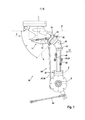
[029] Figura 1 - Uma representação esquemática de um aparelho de separação de tendões,[029] Figure 1 - A schematic representation of a tendon separation device,
[030] Figura 2 - O aparelho de separação de tendões de acordo com a Figura 1, em uma vista frontal correspondendo à Vista II da Figura 1,[030] Figure 2 - The tendon separation apparatus according to Figure 1, in a frontal view corresponding to View II of Figure 1,
[031] Figura 3 - É uma representação esquemática de um aparelho de processamento com um aparelho de separação de tendões, de acordo com as Figuras 1 e 2 em que um dispositivo de retenção é mostrado de forma esquemática com uma carcaça selada na mesma no aparelho de processamento, sendo a carcaça mostrada sem os filés de peito, os quais ainda estão na carcaça, para prover uma melhor vista geral,[031] Figure 3 - It is a schematic representation of a processing apparatus with a tendon separation apparatus, according to Figures 1 and 2 in which a holding device is shown schematically with a sealed housing in the apparatus processing, the carcass being shown without the breast fillets, which are still in the carcass, to provide a better overview,
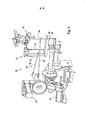
[032] Figura 4 - É uma representação em perspectiva do aparelho de separação de tendões com elementos transportadores,[032] Figure 4 - It is a perspective representation of the tendon separation device with transport elements,
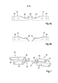
[033] Figura 5 - É uma representação esquemática das facas de degola engajadas com a carcaça,[033] Figure 5 - It is a schematic representation of the sticking knives engaged with the carcass,
[034] Figura 6 - Mostra modalidades adicionais das facas de degola, e[034] Figure 6 - Shows additional modes of the sticking knives, and
[035] Figura 7 - É uma representação esquemática dos elementos transportadores com facas de degola.[035] Figure 7 - It is a schematic representation of the conveyor elements with sticking knives.
[036] A invenção diz respeito a um aparelho de separação de tendões para a separação automática de tendões e/ou partes de tendões presentes em filés de peito internos de corpos de ave eviscerados os quais tiveram as asas completamente removidas, particularmente durante a filetagem de capas de filé de um frango. É claro que o aparelho de separação de tendões é ainda projetado e configurado para filetar capas de filé/metades frontais de outros corpos de aves. Este aparelho de separação de tendões pode ser visto como uma única unidade, por exemplo como um kit de retroapetrechamento ou peça de substituição em aparelhos de processamento existentes. No entanto, a invenção se refere ainda a tal aparelho de separação de tendões como parte de um aparelho de processamento em que uma pluralidade de estações de processamento é vista em uma linha de processamento, uma das quais pode ser o aparelho de separação de tendões.[036] The invention relates to a tendon separating apparatus for the automatic separation of tendons and / or parts of tendons present in internal breast fillets of eviscerated bird bodies which had their wings completely removed, particularly during filleting. chicken fillet covers. It is clear that the tendon separator is still designed and configured to fillet fillet layers / front halves of other bird bodies. This tendon separator can be seen as a single unit, for example as a retrofit kit or replacement part in existing processing devices. However, the invention still relates to such a tendon separating apparatus as part of a processing apparatus in which a plurality of processing stations are seen on a processing line, one of which may be the tendon separating apparatus.
[037] O aparelho de separação de tendões 10 mostrado nas Figuras 1 e 2 para a separação automática de tendões e/ou partes de tendões presentes em filés de peito internos de corpos de aves eviscerados os quais tiveram as asas completamente removidas, em que tanto o filé de peito deitado diretamente na carcaça 11 como o filé de peito externo que cobre o filé de peito interno estão em sua posição natural, e os corpos de aves são transportados, com as articulações de ombro 12 para a frente, na direção de transporte T ao longo de uma rota de transporte que define o plano de transporte E, em que o osso de peito 13 voltado diretamente para baixo é orientado na direção longitudinal da direção de transporte T e paralelo a esta, compreendendo um par de meios de separação 14, 15 para separar os tendões e/ou partes de tendões do filé de peito interno. Os dois meios de separação 14, 15 estão em lados opostos da rota de transporte.[037] The
[038] O referido aparelho de separação de tendões 10, o qual é usualmente fixado a uma moldura, um suporte ou um alojamento de um aparelho de processamento 16, o qual é descrito mais abaixo, se distingue de acordo com a invenção pelos meios de separação 14, 15 serem construídos como facas de degola 17, 18 em que cada faca de degola 17, 18 é projetada e configurada para executar pelo menos dois movimentos de corte de diferentes direções de movimento, sendo os dois movimentos de corte superponíveis. Isto significa que a opção de sobrepor os movimentos de corte assegura uma orientação individual de corte para cada faca de degola 17, 18 tendo pelo menos dois eixos de movimento independentes. Com relação às facas de degola 17, 18 é entendido que significam todas as ferramentas de separação que asseguram a penetração seletiva ou direcionada no corpo de ave e que apresenta pelo menos uma borda cortante 19, 20 com a qual o corte de extirpação pode ser executado.[038] Said
[039] Os aspectos e desenvolvimentos adicionais descritos abaixo representam modalidades preferidas da invenção em cada caso, considerados isoladamente ou em combinações uns com os outros.[039] The additional aspects and developments described below represent preferred embodiments of the invention in each case, considered alone or in combinations with each other.
[040] Em uma modalidade preferida, cada faca de degola 17, 18 é posicionada em um elemento transportador 21, 22 pivotável em torno de um eixo de rotação K, sendo o referido elemento por sua vez fixado em uma alavanca de pivô 23, 24 pivotável em torno de um eixo de rotação Z. Na modalidade descrita, o elemento transportador 21, 22 é uma seção em forma de U com uma placa de cobertura 23 e paredes laterais 26, 27. Há uma placa de retenção 28 para a faca de degola 17, 18 construída na placa de cobertura 25. A placa de retenção 28 é preferivelmente perpendicular à placa de cobertura 25 mas pode ainda ser orientada em outro ângulo obliquo com relação à placa de cobertura 25. As facas de degola 17, 18 são fixadas na placa de retenção 28. O elemento transportador 21, 22 pode ser construído em uma ou mais partes. É obvio que o elemento transportador 21, 22 pode ainda ser construído de outra maneira, tal como em uma estrutura de suporte, elemento de alavanca, solução de rebordo ou similar.[040] In a preferred embodiment, each sticking
[041] O elemento transportador 21, 22 é posicionado para ser pivotável em um elemento de rebordo 29. O elemento de rebordo 29 compreende um parafuso de eixo 30 que compreende o elemento transportador 21, 22 com suas paredes laterais 26, 27 rotativas em torno do eixo de rotação K. No entanto, outras soluções podem ser usadas para pivotar o elemento transportador 21, 22 em torno do eixo de rotação K, tais como um projeto de haste, uma solução de dobradiça, ou similar. O elemento transportador 21, 22 é fixado de forma segura porém removível à alavanca de pivô 23, 24 por meio do elemento de rebordo 29. As alavancas de pivô 23, 24 são simples seções na modalidade mostrada. Os elementos transportadores 21, 22 são fixados na extremidade livre das alavancas de pivô 23, 24. As alavancas de pivô 23, 24 são suportadas na extremidade oposta e capazes de girar em torno do eixo de rotação Z. Para isso um parafuso de eixo 57 que é montado em um transportador 42 pode ser posicionado na alavanca de pivô 23, 24, por exemplo. No entanto, outras soluções podem ainda ser usadas para pivotar a alavanca de pivô 23, 24 em torno do eixo de rotação Z, tais como um projeto de haste, uma solução de dobradiça, ou similar.[041] The
[042] O eixo de rotação Z é preferivelmente orientado em paralelo ao plano de transporte E e na direção da direção de transporte T de tal modo que a faca de degola 17, 18 é capaz de ser movida transversalmente à direção de transporte T em direção a e afastando-se do corpo de ave. A expressão plano de transporte não é um plano bidimensional em um sentido estritamente matemático no presente caso. Uma vez que os corpos de aves apresentam uma certa espessura, a expressão é somente compreendida no sentido de que os corpos de aves são transportados em uma direção horizontal paralela a um transportador do aparelho de processamento 16 (ver Figura 1 ou 3, por exemplo). O movimento das facas de degola 17, 18, transversal à direção de transporte T inclui ainda, explicitamente, junto com a faca de degola 17, 18 atingindo o corpo da ave perpendicularmente à direção de transporte T, uma facada da faca de degola 17, 18 no corpo da ave em um ângulo não igual a 90°, isto é, em um ângulo agudo. A orientação do eixo de rotação Z descrita permite a penetração lateral das facas de degola 17, 18 no corpo da ave e a retirada desta. Em outras palavras, a rotação ou movimento de pivô em torno do eixo de rotação Z permite o movimento de deslocamento das facas de degola 17, 18 de uma posição de espera, em que as facas de degola 17, 18 permitem o transporte do corpo de ave através do aparelho de separação de tendões 10 sem colisão, para uma posição de separação, em que as facas de degola 17, 18 estão localizadas no corpo de ave para executar o corte de extirpação, e retornar. Em outras modalidades, o eixo de rotação Z pode ainda ser inclinado em um ângulo agudo com relação ao plano de transporte E e/ou à direção de transporte T.[042] The axis of rotation Z is preferably oriented parallel to the transport plane E and in the direction of transport direction T such that the sticking
[043] O eixo de rotação K é preferivelmente orientado paralelo à direção de transporte T em um ângulo α com relação ao plano de transporte E de tal modo que a faca de degola 17, 18 é capaz de ser movida para cima ou para baixo com um componente vertical com relação ao plano de transporte E. Este movimento de inclinação ou balanço da faca de degola 17, 18 abaixo do ângulo α torna possível um movimento de corte das facas de degola 17, 18 com um componente vertical e horizontal. Isto significa que resulta uma linha de interseção a qual corta o plano de transporte E e assegura a separação dos tendões ou partes de tendões do filé de peito interno. O ângulo α é maior do que 0° e menor do que 90° e preferivelmente está entre 30° e 50°. Um ângulo α entre 35° e 45° é particularmente preferido. Em modalidades adicionais o eixo de rotação K pode ainda ser inclinado em um ângulo agudo com relação à direção de transporte T.[043] The rotation axis K is preferably oriented parallel to the transport direction T at an angle α with respect to the transport plane E in such a way that the sticking
[044] A superposição do movimento de deslocamento e retirada das facas de degola 17, 18 em torno do eixo de rotação Z por um lado e o movimento de inclinação ou respectivo balanço das facas de degola 17, 18 em torno do eixo de rotação K por outro lado fazem com que o corte de extirpação por extração seja obtido com o qual os tendões e/ou partes de tendões são separados dos filés de peito internos enquanto os filés de peito internos ainda estão em sua posição original, natural na carcaça 11.[044] The superposition of the movement of displacement and removal of the sticking
[045] A inclinação do elemento transportador 21, 22 com relação à alavanca de pivô 23, 24 pode ser opcionalmente determinada para alterar o ângulo α. O elemento de rebordo 29 pode apresentar um orifício de forma alongada correspondente 31 para isto, por exemplo. Este orifício 31, curvado, alongado, em forma de arco constitui ainda uma parada para o movimento de formação ao mesmo tempo. Alternativamente ou adicionalmente, a placa de retenção 28 pode ainda ser ajustável no elemento transportador 21, 22 em sua orientação com relação à placa de cobertura 25, por exemplo por uma pluralidade de posições indexadas para ser capaz de adaptar a posição das facas de degola 17, 18 com relação ao corpo de ave.[045] The inclination of the
[046] Na modalidade descrita, as facas de degola 17, 18 apresentam laminas cortantes 32, 33 as quais são preferivelmente desenhadas de forma aproximadamente triangular. Além disso, as facas de degola 17, 18 compreendem um corpo de montagem 34, 35 o qual é preferivelmente projetado em uma única pela com as laminas cortantes 32, 33. As facas de degola 17, 18 são fixadas de modo firme mas removível no corpo de montagem 34, 35 através das placas de retenção 28. As laminas cortantes 32, 33 apresentam suas bordas de corte afiadas 19, 20 de um lado. No lado voltado para fora das bordas de corte 19, 20, existem bordas de orientação 36, 37 as quais são cegas. As bordas cortantes afiadas 19, 20 das laminas cortantes 32, 33 apontam na direção da clavícula 38 da carcaça 11. De modo correspondente, as bordas de orientação cegas 36, 37 das laminas cortantes 32, 33 apontam na direção dos coracóides 39 da carcaça 11. No entanto, as facas de degola 17, 18 podem ainda ser desenhadas de outra maneira. As figuras 6 a+b mostram outras modalidades preferidas das facas de degola 17, 18. As facas de degola 17, 18 de acordo com a Figura 6a apresentam uma “região rosqueada” arredondada 60. Em outras palavras, a primeira ponta das facas de degola 17, 18 que penetra no corpo de ave é projetada como sendo cega. Isto protege o filé de peito durante a penetração no corpo de ave. As laminas cortantes 64, 65 das facas de degola 17, 18 são preferivelmente projetadas com ligeira curvatura. As laminas cortantes 61, 62 das facas de degola 17, 18 mostradas na Figura 6b são projetadas com um formato de gancho. Esta modalidade apresenta ainda uma primeira ponta que penetra no corpo de ave a qual é desenhada com uma borda afiada.[046] In the described embodiment, the sticking
[047] A ativação das facas de degola 17, 18, isto é, a execução dos movimentos de pivô em torno dos eixos de rotação Z e K, preferivelmente ocorre através de servo motores 40, 41. Pelo menos dois servo motores 40, 41 são designados para as facas de degola 17, 18 por meio dos quais as facas de degola 17, 18 são capazes de ser movidas de uma posição de espera para uma posição de corte ou separação e vice versa e para executar os movimentos de corte. Ao invés dos servo motores 40, 41, outros meios de impulsão adequados podem ainda ser usados. Cada faca de degola 17, 18 pode ser controlada individualmente. Preferivelmente, duas alavancas de pivô 23, 24 são posicionadas em um transportador comum 42. O transportador 42 é preferivelmente projetado para pivotar em torno de um eixo de rotação S, o qual corre paralelo ao plano de transporte E e transversal à direção de transporte T, por exemplo projetado para pivotar por meio de um servo motor 63. Em outras palavras, as alavancas de pivô 23, 24 e portanto os elementos transportadores 21, 22 com as facas de degola 17, 18 podem ser movidos com um componente de movimento na direção de transporte T e de volta, de modo que as facas de degola 17, 18 podem ser movidas ao longo pelo menos temporariamente com o aparelho de retenção 43 que transporta o corpo de ave. Este movimento de pivô em torno do eixo de rotação S, que essencialmente permite um “acompanhamento” limitado das facas de degola 17, 18 pode ser superposto com os movimentos de pivô em torno dos eixos de rotação Z e K de modo que um movimento “fluido” ou contínuo de separação das facas de degola 17, 18 é obtido. Alternativamente, o movimento de acompanhamento pode ainda ocorrer de uma maneira linear, por exemplo por meio de um deslize ou similar.[047] The activation of the sticking
[048] Conforme mencionado previamente, as facas de degola 17, 18 podem ainda ser controladas uma a uma e individualmente. No entanto, as facas de degola podem ainda opcionalmente ser sincronizadas uma com a outra. Existe a possibilidade para a sincronização eletrônica. Na modalidade ilustrada, as facas de degola 17, 18 são conectadas mecanicamente e de modo operativo uma com a outra por meio de hastes de sincronização 44. Isto permite que os movimentos de corte das facas de degola 17, 18 sejam executados simultaneamente. Uma haste de sincronização 45, 46 é designada para cada uma das duas alavancas de pivô 23, 24 em que os braços são capazes de ser ativados sincronicamente pelo servo motor 40. Uma haste de sincronização 47, 48 é similarmente designada para cada um de ambos os elementos transportadores 21, 22 em que os braços são capazes de ser ativados sincronicamente pelo servo motor 41. É óbvio que a sincronização pode ainda ser implementada de outra maneira. Uma haste de ativação opcional 45 é ainda provida para rotação em torno do eixo de rotação S. Esta pode ainda ser conectada a um servo motor ou outro meio de ativação.[048] As previously mentioned, sticking
[049] Conforme mencionado, a invenção compreende ainda um aparelho de processamento 16. A Figura 3 mostra somente de modo esquemático tal aparelho de processamento 16 para remover a carne de corpos de aves eviscerados cujas asas foram completamente removidas, em que o referido aparelho compreende estações de processamento 50 posicionadas em uma linha de processamento 49. Além disso, o aparelho de processamento 16 compreende uma esteira transportadora 51 com meios de retenção 43 posicionados em séries ao longo da linha de processamento 49 para transportar corpos de aves suportados nos meios de retenção 43 e orientar estes ao longo das estações de processamento 50. Além disso, pelo menos um aparelho de medição 52 que emite sinais de medição para registrar aspectos individuais dos corpos de aves durante seu transporte e um dispositivo de controle 53 para controlar a operação das estações de processamento 50 o qual recebe os sinais de medição fazem parte do aparelho de processamento 16. Uma das estações de processamento 50 é um aparelho de separação de tendões 10 conforme descrito em detalhes acima, de acordo com a invenção.[049] As mentioned, the invention further comprises a
[050] O princípio do método para o aparelho de processamento 16, incluindo o aparelho de remoção de tendões 10 de acordo com a invenção, o qual é incorporado no aparelho de processamento 16, é explicado em detalhes abaixo, com base nas figuras.[050] The principle of the method for the
[051] A essência do método inventivo para a separação automática de tendões e/ou partes de tendões presentes nos filés de peito internos de corpos de aves eviscerados cujas asas foram completamente removidas, em que tanto o filé de peito interno encostado diretamente na carcaça como o filé de peito externo que o cobre estão em sua posição natural, consiste no fato do corpo de ave ser transportado, com as articulações de ombro para a frente, em uma direção de transporte T ao longo de uma rota de transporte que define o plano de transporte E, em que o osso de peito direcionado para baixo é orientado na direção longitudinal da direção de transporte T e paralelo a esta, quando facas de degola de ambos os lados são inseridas no corpo de ave abaixo dos tendões e/ou partes de tendões e em seguida pelo menos dois movimentos de corte são realizados em diferentes direções de movimento com cada uma das facas de degola, sendo os dois movimentos de corte superpostos um ao outro. Este método é preferivelmente executado mecanicamente e automaticamente com um aparelho de separação de tendões 10 conforme descrito acima. Este método previamente descrito é ainda preferivelmente configurado em um processo linear em um aparelho de processamento 16, com o seguinte modo de funcionamento.[051] The essence of the inventive method for the automatic separation of tendons and / or parts of tendons present in the internal breast fillets of eviscerated bird bodies whose wings have been completely removed, in which both the internal breast fillet leaning directly on the carcass and the outer breast fillet that covers it is in its natural position, consists of the fact that the bird's body is transported, with the shoulder joints forward, in a transport direction T along a transport route that defines the plane of transport E, in which the breast bone directed downwards is oriented in the longitudinal direction of the transport direction T and parallel to it, when sticking knives on both sides are inserted into the body of the bird below the tendons and / or parts of tendons and then at least two cutting movements are carried out in different directions of movement with each of the sticking knives, the two cutting movements being superimposed on each other. This method is preferably carried out mechanically and automatically with a
[052] Um corpo de ave (uma carcaça com filés de peito) selado no meio de retenção 43 é transportado por uma pluralidade de estações de processamento 50 ao longo da rota de transporte no plano de transporte E na direção de transporte T por meio da esteira 51 (ver Figura 3, por exemplo). Na referida figura, os filés de peito foram omitidos para a melhor compreensão, particularmente com relação à carcaça. É claro que os filés de peito, isto é, filés de peito internos e filés de peito externos, ainda se encontram em sua posição original, natural na carcaça tanto na área do aparelho de medição 52 como na área do aparelho de remoção de tendões 10. Cada corpo de ave atinge o aparelho de medição 52 com as articulações de ombro 12 para a frente e o osso de peito 13 direcionado para baixo e orientado na direção longitudinal da direção de transporte T e paralelo a esta. O aparelho de medição 52 é usado, por exemplo, para registrar aspectos individuais do corpo de ave, preferivelmente pela medição da posição das articulações de ombro 12 (ver particularmente a Figura 3). Os dados e informações obtidos pelo aparelho de medição 52 são recebidos pelo dispositivo de controle 53, processados e passados para as estações de processamento seguintes 50; por exemplo, na modalidade exemplificativa do aparelho de remoção de tendões 10 para a operação deste.[052] A bird body (a carcass with breast fillets) sealed in the holding
[053] Ao alcançar o aparelho de separação de tendões 10, as facas de degola 17, 18 estão em sua posição de espera, de modo que o corpo de ave pode primeiro penetrar no aparelho de separação de tendões 10 sem colidir com as clavículas 38 formando o osso de peito direcionado para a frente. Com base nos dados de medição disponíveis, as facas de degola 17, 18 são então movidas pelo controle da posição de espera para a posição de corte de modo que as facas de degola 17, 18 são inseridas no corpo de ave entre o coracóide 39 e a clavícula 38 acima do tendão localizado no filé de peito interno sem danificar o filé de peito externo e o filé de peito interno. Em seguida um corte de extirpação produzido por dois movimentos de corte sobrepostos é executado pelas facas de degola 17, 18 sendo movidas tanto obliquamente para abaixo do coracóide 39 na direção da clavícula 38 e afastando-se do corpo de ave para fora também. A Figura 5 mostra as facas de degola 17, 18 em tal posição entre o coracóide 39 e a clavícula 38, em que as facas de degola 17, 18 já se encontram em movimento longe do coracóide 39. O corte de extirpação resultante separa os tendões e/ou partes de tendões que estão localizados nos filés de peito internos em ambos os lados do corpo de ave enquanto os filés de peito internos ainda se encontram em sua posição original, natural.[053] When reaching the
[054] Para executar os movimentos de inserção e corte, as facas de degola 17, 18 cada uma se move em torno de pelo menos dois eixos de rotação Z e K. As facas de degola 17, 18 são cada uma inserida lateralmente no corpo de ave até o coracóide 39 por um movimento de rotação ou pivô em torno do eixo de rotação Z. Este é apenas um movimento de deslocamento das facas de degola 17, 18 no corpo de ave ou dentro deste. As facas de degola 17,18 então se posicionam preferivelmente com sua borda de orientação cega 36, 37 no coracóide 39. Agora as facas de degola 17, 18 executam um movimento de pivô em torno do eixo de rotação K obliquamente com relação ao plano de transporte E, para baixo ao longo do osso de peito enquanto as facas de degola 17, 18 simultaneamente pivotam para fora do corpo de ave em torno do eixo de rotação Z. O corte de extirpação dos tendões ou partes de tendões resulta destes movimentos sobrepostos.[054] To perform the insertion and cutting movements, the sticking
[055] As facas de degola 17, 18 podem ainda opcionalmente serem guiadas ao longo do corpo de ave na direção de transporte T pelo menos parcialmente durante o corte de extirpação acima descrito. Com o movimento de pivô da unidade inteira, consistindo das alavancas de pivô 23, 24, elementos transportadores 21, 22 e as facas de degola 17, 18 posicionadas nestas, em torno do eixo de rotação S, um “acompanhamento” limitado das facas de degola 17, 18 pode ser obtido na direção de transporte T uma vez que o movimento de pivô contempla ainda um componente horizontal. As mudanças em altura resultantes do movimento de pivô pelo componente vertical podem ser compensadas pelos movimentos de pivô em torno dos eixos de rotação Z e K. O “acompanhamento” pode ainda ocorrer linearmente por meio de uma rampa, por exemplo.[055] Sticking
Claims (16)
Applications Claiming Priority (3)
| Application Number | Priority Date | Filing Date | Title |
|---|---|---|---|
| EP12153328.5 | 2012-01-31 | ||
| EP20120153328 EP2622962B1 (en) | 2012-01-31 | 2012-01-31 | Tendon separation apparatus and processing apparatus with such a tendon separation apparatus and method for automatic separation of tendons and/or tendon sections on inner breast filets |
| PCT/EP2012/074225 WO2013113428A1 (en) | 2012-01-31 | 2012-12-03 | Sinew removal device, processing device having such a sinew removal device, and method for the automatic removal of sinews and/or sinew portions situated on inner breast fillets |
Publications (3)
| Publication Number | Publication Date |
|---|---|
| BR112014018166A2 BR112014018166A2 (en) | 2017-06-20 |
| BR112014018166A8 BR112014018166A8 (en) | 2019-01-29 |
| BR112014018166B1 true BR112014018166B1 (en) | 2021-02-02 |
Family
ID=47351602
Family Applications (1)
| Application Number | Title | Priority Date | Filing Date |
|---|---|---|---|
| BR112014018166-7A BR112014018166B1 (en) | 2012-01-31 | 2012-12-03 | apparatus for removing tendons, processing device having said apparatus for removing tendons, and method for automatic removal of tendons and / or parts of tendons located in the internal breast fillets |
Country Status (9)
| Country | Link |
|---|---|
| US (1) | US9433223B2 (en) |
| EP (1) | EP2622962B1 (en) |
| CN (1) | CN104105406B (en) |
| AU (1) | AU2012367911B2 (en) |
| BR (1) | BR112014018166B1 (en) |
| CA (1) | CA2861942C (en) |
| DK (1) | DK2622962T3 (en) |
| ES (1) | ES2531395T3 (en) |
| WO (1) | WO2013113428A1 (en) |
Families Citing this family (7)
| Publication number | Priority date | Publication date | Assignee | Title |
|---|---|---|---|---|
| NL2017236B1 (en) | 2016-07-25 | 2018-01-31 | Meyn Food Processing Tech Bv | Method and device for processing a carcass part of slaughtered poultry in a processing line |
| NL2017997B1 (en) * | 2016-12-14 | 2018-06-26 | Meyn Food Processing Tech Bv | Vent cutter and method for cutting loose tissue around a vent of poultry |
| EP3689147A1 (en) * | 2019-01-29 | 2020-08-05 | Nordischer Maschinenbau Rud. Baader GmbH + Co. KG | Device and method for separating at least one breast fillet of a gutted poultry carcass or a part thereof with a tendon connecting a carcass of the poultry carcass or a part thereof and tool unit for this purpose |
| CN111802433B (en) * | 2019-04-12 | 2022-08-19 | 饶喜钊 | Muscle-raising device for meat |
| DE102019118268B3 (en) * | 2019-07-05 | 2020-10-22 | Nordischer Maschinenbau Rud. Baader Gmbh + Co. Kg | Device and method for cutting into breast fillets connected to one another at least in the region of a breastbone of a carcass of poultry carcasses or parts thereof along the breastbone |
| DE102020117866A1 (en) | 2020-07-07 | 2022-01-13 | Nordischer Maschinenbau Rud. Baader Gmbh + Co. Kg | Device and method for the automatic processing of gutted poultry carcasses or parts thereof |
| CN113826681A (en) * | 2021-10-25 | 2021-12-24 | 徐州恒阳禽业有限公司 | Automatic press from both sides tight and reciprocal drumstick of scraping meat device of shaving |
Family Cites Families (12)
| Publication number | Priority date | Publication date | Assignee | Title |
|---|---|---|---|---|
| CN85102729A (en) * | 1985-04-15 | 1986-10-15 | 斯托克Pmt公司 | Be used to cut the method and the device of the part of the bird health after butchering |
| US4873746A (en) * | 1988-01-25 | 1989-10-17 | Simon-Johnson Company | Method and apparatus for removing breast meat from poultry carcass |
| DE3811317A1 (en) * | 1988-04-02 | 1989-10-19 | Nordischer Maschinenbau | METHOD FOR OBTAINING THE MEAT POULTRY Slaughtered BY THE BODY AND DEVICE FOR IMPLEMENTING THE METHOD |
| US5228881A (en) * | 1991-04-03 | 1993-07-20 | Gordex Corporation | Poultry leg boning apparatus |
| US5314374A (en) * | 1993-06-14 | 1994-05-24 | Jay Koch | Apparatus for removing tenders from a poultry carcass |
| US5395283A (en) * | 1994-03-23 | 1995-03-07 | Gasbarro; Geno N. | Automatic tendon removal apparatus |
| DE19848498A1 (en) * | 1998-10-21 | 2000-05-04 | Nordischer Maschinenbau | Filleting device |
| NL1012683C2 (en) | 1999-07-23 | 2001-01-24 | Stork Pmt | Method for recovering an inner fillet from a poultry carcass part, and device for processing the poultry carcass part. |
| JP3497476B2 (en) * | 2001-01-30 | 2004-02-16 | 株式会社前川製作所 | Method and apparatus for harvesting hollow carcasses |
| US6890251B2 (en) * | 2002-10-15 | 2005-05-10 | Tyson Foods, Inc. | Apparatus and method for removing poultry tenders |
| WO2004112489A1 (en) * | 2003-06-20 | 2004-12-29 | Mayekawa Mfg.Co., Ltd. | Method of separating oyster meat from thigh and apparatus therefor |
| DE102004003922B3 (en) * | 2004-01-27 | 2005-03-10 | Georg Krause | Assembly to remove tendons and separated tendons from turkey breast meat has oscillating cutter knife and tendon suction removal unit |
-
2012
- 2012-01-31 DK DK12153328T patent/DK2622962T3/en active
- 2012-01-31 ES ES12153328T patent/ES2531395T3/en active Active
- 2012-01-31 EP EP20120153328 patent/EP2622962B1/en not_active Not-in-force
- 2012-12-03 CA CA2861942A patent/CA2861942C/en active Active
- 2012-12-03 WO PCT/EP2012/074225 patent/WO2013113428A1/en active Application Filing
- 2012-12-03 BR BR112014018166-7A patent/BR112014018166B1/en not_active IP Right Cessation
- 2012-12-03 CN CN201280068420.2A patent/CN104105406B/en not_active Expired - Fee Related
- 2012-12-03 US US14/375,814 patent/US9433223B2/en active Active
- 2012-12-03 AU AU2012367911A patent/AU2012367911B2/en not_active Ceased
Also Published As
| Publication number | Publication date |
|---|---|
| BR112014018166A2 (en) | 2017-06-20 |
| CN104105406B (en) | 2016-02-24 |
| CA2861942A1 (en) | 2013-08-08 |
| US20150105008A1 (en) | 2015-04-16 |
| BR112014018166A8 (en) | 2019-01-29 |
| CA2861942C (en) | 2016-01-12 |
| US9433223B2 (en) | 2016-09-06 |
| DK2622962T3 (en) | 2015-03-09 |
| ES2531395T3 (en) | 2015-03-13 |
| EP2622962B1 (en) | 2014-12-17 |
| AU2012367911B2 (en) | 2015-07-16 |
| EP2622962A1 (en) | 2013-08-07 |
| WO2013113428A1 (en) | 2013-08-08 |
| AU2012367911A1 (en) | 2014-08-28 |
| CN104105406A (en) | 2014-10-15 |
Similar Documents
| Publication | Publication Date | Title |
|---|---|---|
| BR112014018166B1 (en) | apparatus for removing tendons, processing device having said apparatus for removing tendons, and method for automatic removal of tendons and / or parts of tendons located in the internal breast fillets | |
| BR112014000304A2 (en) | apparatus and method for automatically separating the collarbone from gutted bird bodies | |
| ES2376372T3 (en) | PROCEDURE AND DEVICE OF TREATMENT OF A PIECE OF SACRIFIED CORRAL BIRD. | |
| DK2413702T3 (en) | METHODS AND DEVICE FOR CUTTING ANIMAL BODY | |
| ES2703674T3 (en) | Shoulder incision apparatus and shoulder incision method | |
| BR112016029773B1 (en) | CONTOUR MEASUREMENT APPARATUS AND METHOD FOR MEASURING A CONTOUR OF A POULTRY CARCASS, AND BONING DEVICE FOR A POULTRY CARCASS | |
| RU2619254C1 (en) | Method, system and guide unit sets for separating sets of internal organs drawn from slaughtered poultry | |
| JP6069517B2 (en) | Apparatus and method for processing the body of slaughtered poultry | |
| BRPI1102414B1 (en) | method for filleting birds or parts of birds and filleting system for such birds or parts of birds | |
| ES2528232T3 (en) | Device and procedure to completely separate breast fillets from the carcass already partially separated from the carcass of an eviscerated poultry body | |
| RU2653079C1 (en) | Guide element, guide assembly, system and method of separation of viscera set extracted from slaughtered poultry | |
| US6277020B1 (en) | Method and apparatus for removing meat from poultry carcasses | |
| BR112015026924B1 (en) | system and method for processing carcass parts | |
| BR112018067760B1 (en) | PRE-EVISCERATION DEVICE FOR PREPARING EVISCERATION OF SLAUGHTERED AND DECEADED POULTRY, PRE-EVISCERATION RELEASE TOOL FOR PREPARING EVISCERATION OF SLAUGHTERED AND DECEADED POULTRY, AND METHOD FOR PREPARING EVISCERATION OF SLAUGHTERED BEACHED POULTRY | |
| ES2662353T3 (en) | Provision for lateral grooving on both sides of the skin of an animal channel slaughtered in astride position, support body of such an arrangement to astride the channel, processing machine that uses the grooving arrangement of the skin as well as corresponding procedure for skin grooving | |
| BR112018005108B1 (en) | Apparatus, system and method for removing the wishbone from the breast cap of poultry | |
| BR102013009699B1 (en) | apparatus and method for preparing a tenders poultry carcase | |
| BR112018006845B1 (en) | A METHOD, A GUIDE ASSEMBLY AND A SYSTEM FOR SEPARATING SETS OF INVISCERATED VISCERA FROM SLAUGHTERED BIRDS | |
| BR112021014430A2 (en) | DEVICE AND METHOD FOR SEPARATING AT LEAST ONE TENDON THAT CONNECTS A BREAST FILLE OF AN EVISCERATED POULTRY BODY, OR A PART THEREOF, TO A BIRD BODY CARCASS, OR A PART THEREOF, AND A TOOL UNIT FOR THE SAME | |
| BR102012030459A2 (en) | boner for poultry parts such as thighs or drumsticks | |
| RU2526634C1 (en) | Device for two-sided lateral cutting of skin of drawn animal carcass in fitted-on position, support element of such device for animal carcass fitting-on, treatment machine using skin cutting device as well as corresponding cutting method | |
| ES2495290A2 (en) | Procedure and apparatus for continuous longitudinal separation of cooked tuna (Machine-translation by Google Translate, not legally binding) |
Legal Events
| Date | Code | Title | Description |
|---|---|---|---|
| B06F | Objections, documents and/or translations needed after an examination request according [chapter 6.6 patent gazette] | ||
| B06F | Objections, documents and/or translations needed after an examination request according [chapter 6.6 patent gazette] | ||
| B06I | Publication of requirement cancelled [chapter 6.9 patent gazette] |
Free format text: ANULADA A PUBLICACAO CODIGO 6.6.1 NA RPI NO 2462 DE 13/03/2018 POR TER SIDO INDEVIDA. |
|
| B08F | Application dismissed because of non-payment of annual fees [chapter 8.6 patent gazette] |
Free format text: PAGAR RESTAURACAO. |
|
| B08H | Application fees: decision cancelled [chapter 8.8 patent gazette] |
Free format text: ANULADA A PUBLICACAO CODIGO 8.6 NA RPI NO 2509 DE 05/02/2019 POR TER SIDO INDEVIDA. UMA VEZ QUE O RECOLHIMENTO DA 6A ANUIDADE FOI EFETUADO EM 18/12/2017, ATRAVES DA GRU 29409161711549796. |
|
| B06U | Preliminary requirement: requests with searches performed by other patent offices: procedure suspended [chapter 6.21 patent gazette] | ||
| B09A | Decision: intention to grant [chapter 9.1 patent gazette] | ||
| B16A | Patent or certificate of addition of invention granted [chapter 16.1 patent gazette] |
Free format text: PRAZO DE VALIDADE: 20 (VINTE) ANOS CONTADOS A PARTIR DE 03/12/2012, OBSERVADAS AS CONDICOES LEGAIS. |
|
| B21F | Lapse acc. art. 78, item iv - on non-payment of the annual fees in time |
Free format text: REFERENTE A 11A ANUIDADE. |
|
| B24J | Lapse because of non-payment of annual fees (definitively: art 78 iv lpi, resolution 113/2013 art. 12) |
Free format text: EM VIRTUDE DA EXTINCAO PUBLICADA NA RPI 2751 DE 26-09-2023 E CONSIDERANDO AUSENCIA DE MANIFESTACAO DENTRO DOS PRAZOS LEGAIS, INFORMO QUE CABE SER MANTIDA A EXTINCAO DA PATENTE E SEUS CERTIFICADOS, CONFORME O DISPOSTO NO ARTIGO 12, DA RESOLUCAO 113/2013. |