BR112014011486B1 - OPTICALLY READABLE CODE HOLDER, CAPSULE COMPRISING AN OPTICALLY READABLE CODE HOLDER AND EDENTED CAPSULE FOR SUPPLYING A BEVERAGE - Google Patents
OPTICALLY READABLE CODE HOLDER, CAPSULE COMPRISING AN OPTICALLY READABLE CODE HOLDER AND EDENTED CAPSULE FOR SUPPLYING A BEVERAGE Download PDFInfo
- Publication number
- BR112014011486B1 BR112014011486B1 BR112014011486-2A BR112014011486A BR112014011486B1 BR 112014011486 B1 BR112014011486 B1 BR 112014011486B1 BR 112014011486 A BR112014011486 A BR 112014011486A BR 112014011486 B1 BR112014011486 B1 BR 112014011486B1
- Authority
- BR
- Brazil
- Prior art keywords
- capsule
- light
- readable code
- optically readable
- base structure
- Prior art date
Links
- 239000002775 capsule Substances 0.000 title claims abstract description 176
- 235000013361 beverage Nutrition 0.000 claims abstract description 43
- 239000000969 carrier Substances 0.000 claims abstract description 22
- 238000001579 optical reflectometry Methods 0.000 claims abstract description 3
- 239000004922 lacquer Substances 0.000 claims description 23
- 239000000049 pigment Substances 0.000 claims description 20
- 229910052782 aluminium Inorganic materials 0.000 claims description 17
- XAGFODPZIPBFFR-UHFFFAOYSA-N aluminum Chemical compound [Al] XAGFODPZIPBFFR-UHFFFAOYSA-N 0.000 claims description 17
- 239000000463 material Substances 0.000 claims description 12
- 229910052751 metal Inorganic materials 0.000 claims description 12
- 239000002184 metal Substances 0.000 claims description 12
- 239000000203 mixture Substances 0.000 claims description 11
- 229920000642 polymer Polymers 0.000 claims description 6
- 238000000034 method Methods 0.000 claims description 5
- 238000005119 centrifugation Methods 0.000 claims description 4
- 239000002245 particle Substances 0.000 claims description 4
- BQCADISMDOOEFD-UHFFFAOYSA-N silver Chemical compound [Ag] BQCADISMDOOEFD-UHFFFAOYSA-N 0.000 claims description 4
- 229910052709 silver Inorganic materials 0.000 claims description 4
- 239000004332 silver Substances 0.000 claims description 4
- RYGMFSIKBFXOCR-UHFFFAOYSA-N copper Chemical compound [Cu] RYGMFSIKBFXOCR-UHFFFAOYSA-N 0.000 claims description 2
- 229910052802 copper Inorganic materials 0.000 claims description 2
- 239000010949 copper Substances 0.000 claims description 2
- PCHJSUWPFVWCPO-UHFFFAOYSA-N gold Chemical compound [Au] PCHJSUWPFVWCPO-UHFFFAOYSA-N 0.000 claims description 2
- 229910052737 gold Inorganic materials 0.000 claims description 2
- 239000010931 gold Substances 0.000 claims description 2
- 239000011159 matrix material Substances 0.000 claims description 2
- 229910052718 tin Inorganic materials 0.000 claims description 2
- 239000011135 tin Substances 0.000 claims description 2
- ATJFFYVFTNAWJD-UHFFFAOYSA-N tin hydride Chemical compound [Sn] ATJFFYVFTNAWJD-UHFFFAOYSA-N 0.000 claims description 2
- XEEYBQQBJWHFJM-UHFFFAOYSA-N iron Chemical compound [Fe] XEEYBQQBJWHFJM-UHFFFAOYSA-N 0.000 claims 2
- 229910052742 iron Inorganic materials 0.000 claims 1
- 238000002360 preparation method Methods 0.000 abstract description 12
- 238000002310 reflectometry Methods 0.000 description 33
- 239000000976 ink Substances 0.000 description 21
- 230000003287 optical Effects 0.000 description 17
- 239000007788 liquid Substances 0.000 description 16
- 239000004615 ingredient Substances 0.000 description 15
- 239000003973 paint Substances 0.000 description 9
- 238000000605 extraction Methods 0.000 description 8
- 238000004519 manufacturing process Methods 0.000 description 8
- XLYOFNOQVPJJNP-UHFFFAOYSA-N water Substances O XLYOFNOQVPJJNP-UHFFFAOYSA-N 0.000 description 6
- 238000005259 measurement Methods 0.000 description 5
- 230000002745 absorbent Effects 0.000 description 4
- 239000002250 absorbent Substances 0.000 description 4
- 230000015572 biosynthetic process Effects 0.000 description 4
- 238000010586 diagram Methods 0.000 description 4
- 239000012530 fluid Substances 0.000 description 4
- 238000005755 formation reaction Methods 0.000 description 4
- 229920000728 polyester Polymers 0.000 description 4
- -1 polypropylene Polymers 0.000 description 4
- 239000004743 Polypropylene Substances 0.000 description 3
- 239000000853 adhesive Substances 0.000 description 3
- 230000001070 adhesive Effects 0.000 description 3
- 230000001965 increased Effects 0.000 description 3
- 239000012528 membrane Substances 0.000 description 3
- 229920001155 polypropylene Polymers 0.000 description 3
- 238000007639 printing Methods 0.000 description 3
- 239000002904 solvent Substances 0.000 description 3
- 239000000126 substance Substances 0.000 description 3
- 229910000838 Al alloy Inorganic materials 0.000 description 2
- IQPQWNKOIGAROB-UHFFFAOYSA-N [N-]=C=O Chemical compound [N-]=C=O IQPQWNKOIGAROB-UHFFFAOYSA-N 0.000 description 2
- 239000006185 dispersion Substances 0.000 description 2
- 235000013305 food Nutrition 0.000 description 2
- 238000010438 heat treatment Methods 0.000 description 2
- 238000003780 insertion Methods 0.000 description 2
- 239000004033 plastic Substances 0.000 description 2
- 229920003023 plastic Polymers 0.000 description 2
- 229920000915 polyvinyl chloride Polymers 0.000 description 2
- 230000001681 protective Effects 0.000 description 2
- 240000007524 Camellia sinensis var. sinensis Species 0.000 description 1
- 239000004593 Epoxy Substances 0.000 description 1
- 210000004080 Milk Anatomy 0.000 description 1
- 239000004698 Polyethylene (PE) Substances 0.000 description 1
- 241001426756 Senna tora Species 0.000 description 1
- 210000001138 Tears Anatomy 0.000 description 1
- 239000006096 absorbing agent Substances 0.000 description 1
- 239000011358 absorbing material Substances 0.000 description 1
- 238000004026 adhesive bonding Methods 0.000 description 1
- 229910045601 alloy Inorganic materials 0.000 description 1
- 239000000956 alloy Substances 0.000 description 1
- 235000008452 baby food Nutrition 0.000 description 1
- 230000004888 barrier function Effects 0.000 description 1
- 238000006065 biodegradation reaction Methods 0.000 description 1
- 230000005540 biological transmission Effects 0.000 description 1
- 238000009835 boiling Methods 0.000 description 1
- 235000019219 chocolate Nutrition 0.000 description 1
- 230000000052 comparative effect Effects 0.000 description 1
- 150000001875 compounds Chemical class 0.000 description 1
- 239000001033 copper pigment Substances 0.000 description 1
- 230000002596 correlated Effects 0.000 description 1
- 230000001808 coupling Effects 0.000 description 1
- 238000010168 coupling process Methods 0.000 description 1
- 238000005859 coupling reaction Methods 0.000 description 1
- 125000004122 cyclic group Chemical group 0.000 description 1
- 238000009792 diffusion process Methods 0.000 description 1
- 238000009826 distribution Methods 0.000 description 1
- 230000000694 effects Effects 0.000 description 1
- 230000002708 enhancing Effects 0.000 description 1
- 125000003700 epoxy group Chemical group 0.000 description 1
- 238000005530 etching Methods 0.000 description 1
- 238000011049 filling Methods 0.000 description 1
- 238000001914 filtration Methods 0.000 description 1
- 239000000796 flavoring agent Substances 0.000 description 1
- 235000019634 flavors Nutrition 0.000 description 1
- 239000003365 glass fiber Substances 0.000 description 1
- 239000003292 glue Substances 0.000 description 1
- 238000000227 grinding Methods 0.000 description 1
- 238000003306 harvesting Methods 0.000 description 1
- 238000001802 infusion Methods 0.000 description 1
- 230000003993 interaction Effects 0.000 description 1
- 238000001465 metallisation Methods 0.000 description 1
- 150000002739 metals Chemical class 0.000 description 1
- 235000013336 milk Nutrition 0.000 description 1
- 239000008267 milk Substances 0.000 description 1
- 230000000051 modifying Effects 0.000 description 1
- 238000000465 moulding Methods 0.000 description 1
- 238000007645 offset printing Methods 0.000 description 1
- 230000035515 penetration Effects 0.000 description 1
- 238000001259 photo etching Methods 0.000 description 1
- 230000000704 physical effect Effects 0.000 description 1
- 229920000573 polyethylene Polymers 0.000 description 1
- 239000011148 porous material Substances 0.000 description 1
- 239000000843 powder Substances 0.000 description 1
- 230000003014 reinforcing Effects 0.000 description 1
- 238000007789 sealing Methods 0.000 description 1
- 238000007614 solvation Methods 0.000 description 1
- 235000014347 soups Nutrition 0.000 description 1
- 239000002966 varnish Substances 0.000 description 1
Images


Abstract
DE CÓDIGO OTICAMENTE LEGÍVEL PARA PREPARAR BEBIDA, TAL SUPORTE DE CÓDIGO PROVENDO UM SINAL OTICAMENTE LEGÍVEL MELHORADO. A presente invenção refere-se um suporte de código oticamente legível (30) associado a uma cápsula endentada para suprir bebida a dispositivo para produzir bebida por centrifugação da cápsula, o suporte compreendendo pelo menos uma sequência de símbolos binários, onde cada símbolo é sequencialmente legível por um arranjo de leitura em um dispositivo de leitura externo, enquanto a cápsula é colocada em rotação em torno de um eixo, sendo que os símbolos binários são formados em superfícies refletivas de luz (400-403) e superfícies absorventes de luz (410-414). O suporte de código compreende uma estrutura base (500) que se estende continuamente ao longo da citada sequência de símbolos e porções absorventes de luz discretas descontínuas para formar superfícies absorventes de luz e a estrutura base (500) para formar as superfícies refletivas de luz (400-403) fora das áreas de superfície ocupadas pelas porções absorventes de luz discretas, as citadas porções absorventes de luz discretas (410-414) são dispostas para prover uma refletividade de luz mais baixa que da estrutura base, fora das áreas de superfície ocupadas pelas porções absorventes de luz discretas.OF OPTICALLY READY CODE FOR BEVERAGE PREPARATION, SUCH CODE HOLDER PROVIDING AN IMPROVED OPTICALLY READY SIGNAL. The present invention relates to an optically readable code holder (30) associated with an indented capsule for supplying beverage to a device for producing beverage by centrifuging the capsule, the holder comprising at least a sequence of binary symbols, where each symbol is sequentially readable. by a readout arrangement on an external readout device, while the capsule is placed in rotation around an axis, the binary symbols being formed on light-reflecting surfaces (400-403) and light-absorbing surfaces (410- 414). The code carrier comprises a base structure (500) that extends continuously along said sequence of symbols and discrete discrete light-absorbing portions to form light-absorbing surfaces and the base structure (500) to form the light-reflecting surfaces ( 400-403) outside the surface areas occupied by the discrete light-absorbing portions, said discrete light-absorbing portions (410-414) are arranged to provide lower light reflectivity than the base structure, outside the occupied surface areas. by the discrete light-absorbing portions.
Description
[001] A invenção pertence ao campo de preparação de bebidas,em particular, usando cápsulas contendo ingrediente para preparar uma bebida em uma máquina para preparar bebida. A presente invenção relaciona-se, em particular a suportes de código ótico, adaptados para armazenar informações relativas a cápsulas, associadas ou incorporadas a um suporte de código, leitura e arranjos de processamento, para ler e usar tais informações para preparar uma bebida.[001] The invention pertains to the field of beverage preparation, in particular, using ingredient-containing capsules to prepare a beverage in a beverage preparation machine. The present invention relates in particular to optical code carriers adapted to store information relating to capsules, associated with or incorporated into a code carrier, reading and processing arrangements, for reading and using such information to prepare a beverage.
[002] Para propósito da presente invenção, o termo "bebida" serefere a qualquer substância líquida consumível por seres humanos, tal como, café, chá, chocolate quente ou frio, leite, sopa, alimentos de bebês, por exemplo. O termo "cápsula" se refere a qualquer ingrediente de bebida pré-dosado ou uma combinação de ingredientes (aqui chamados de "ingrediente") encapsulados em um envoltório de qualquer material adequado tal como plástico alumínio material reciclável e/ou biodegradável e suas combinações incluindo sachê flexível ou cartucho rígido contendo o ingrediente.[002] For the purposes of the present invention, the term "beverage" refers to any liquid substance consumable by humans, such as coffee, tea, hot or cold chocolate, milk, soup, baby food, for example. The term "capsule" refers to any pre-dosed beverage ingredient or combination of ingredients (hereinafter referred to as an "ingredient") encapsulated in a shell of any suitable material such as aluminum plastic, recyclable and/or biodegradable material and combinations thereof including flexible sachet or rigid cartridge containing the ingredient.
[003] Certas máquinas de preparação de bebida usam cápsulascontendo um ingrediente, a ser extraído ou dissolvido e/ou um ingrediente armazenado e dosado automaticamente na máquina, é adicionado quando da preparação da bebida. Certas máquinas de preparação de bebida compreendem um meio de enchimento de líquido, incluindo uma bomba para líquidos, usualmente água, que é bombeada a partir de uma fonte de água fria ou aquecida através de meios aquecedores, por exemplo, termoblocos ou similares. Certas máquinas para preparação de bebida são dispostas para preparar bebidas usando um processo de extração por centrifugação. O princípio consiste em suprir o ingrediente de bebida ao recipiente da cápsula, suprir um líquido à cápsula, fazer a cápsula girar em alta rotação, para garantir a interação do líquido com o pó, enquanto cria um gradiente de pressão no líquido na cápsula; a pressão aumentando gradualmente do centro para a periferia do receptáculo. A medida que o líquido atravessa o leito de café, ocorre a extração de compostos de café, e obtém-se um extrato de líquido, fluindo na periferia da cápsula.[003] Certain beverage preparation machines use capsules containing an ingredient, to be extracted or dissolved and/or an ingredient stored and automatically dosed in the machine, is added when preparing the beverage. Certain beverage preparation machines comprise a liquid filling means, including a pump for liquids, usually water, which is pumped from a source of cold or heated water through heating means, for example thermoblocks or the like. Certain beverage preparation machines are arranged to prepare beverages using a centrifuge extraction process. The principle is to supply the beverage ingredient to the capsule container, supply a liquid to the capsule, make the capsule rotate at high rotation, to ensure the interaction of the liquid with the powder, while creating a pressure gradient in the liquid in the capsule; pressure gradually increasing from the center to the periphery of the receptacle. As the liquid passes through the coffee bed, extraction of coffee compounds takes place, and a liquid extract is obtained, flowing in the periphery of the capsule.
[004] Tipicamente, se oferece ao usuário uma gama de cápsulasde diferentes tipos de diferentes ingredientes (por exemplo, diferentes misturas de café de vários sabores) na mesma máquina. As características das bebidas podem ser variadas, variando o conteúdo da cápsula (por exemplo, peso, e misturas de café, etc.) ajustando parâmetros da máquina, tal como volume ou temperatura do líquido suprido, rotação e pressão da bomba. Por conseguinte, há necessidade de identificar o tipo de cápsula inserida na máquina de bebida, para permitir o ajuste adequado dos parâmetros de infusão de acordo com o tipo inserido. Ademais, também é desejável inserir informações adicionais, por exemplo, informações de segurança, tal como data de vencimento, data de fabricação, ou número de série ou lote.[004] Typically, the user is offered a range of capsules of different types of different ingredients (eg different coffee blends of various flavors) in the same machine. Beverage characteristics can be varied by varying the capsule content (eg weight, and coffee blends, etc.) by adjusting machine parameters such as volume or temperature of liquid supplied, pump speed and pressure. Therefore, there is a need to identify the type of capsule inserted into the beverage machine, to allow proper adjustment of the brewing parameters according to the type inserted. In addition, it is also desirable to enter additional information, for example, safety information, such as expiration date, date of manufacture, or serial or batch number.
[005] A WO2010/26053 relaciona-se a um dispositivo deprodução de bebida controlada usando força centrífuga. A cápsula pode compreender um código de barra disposto na face externa da cápsula, provendo o tipo da cápsula e/ou natureza dos ingredientes na cápsula, para indicar um perfil de extração pré-definido para a bebida a ser preparada.[005] WO2010/26053 relates to a controlled beverage production device using centrifugal force. The capsule may comprise a bar code disposed on the outer face of the capsule, providing the type of capsule and/or nature of the ingredients in the capsule, to indicate a predefined extraction profile for the beverage to be prepared.
[006] É conhecido na técnica, por exemplo, a partir da EP1764015A1, um processo de impressão de um código de barra de identificação local na cabeça circular de uma pastilha de café para máquinas de café convencionais.[006] It is known in the art, for example, from EP1764015A1, a process of printing a local identification bar code on the circular head of a coffee pod for conventional coffee machines.
[007] O Pedido de Patente co-pendente PCT/EP11/057670relaciona-se a um suporte adaptado para ser associado ou integrado a uma cápsula para preparação de uma bebida. O suporte compreende uma seção na qual pelo menos uma sequência de símbolos é representada, sendo que cada símbolo é sequencialmente legível por um arranjo de leitura em um dispositivo externo, enquanto a cápsula gira em torno de um eixo de rotação, sendo que cada sequência codifica um conjunto de informações relativas à cápsula. Tal invenção permite prover um grande volume de informação codificada disponível, tal como, cerca de 100 bits de informação redundante ou não- redundante, sem usar leitores de código de barra com partes móveis, por exemplo, em elemento escaneador, que ocasionam sérias questões de confiabilidade. Outra vantagem também consiste em prover a leitura do suporte de código fazendo girar o porta-cápsula. No entanto, uma desvantagem reside no fato de as condições de leitura se tornarem especialmente difíceis por diferentes razões, tal como, por causa de raios de luz que entram e saem, atravessando o porta- cápsula, quando a cápsula está instalada no porta-cápsula, provocando perda de grande parte da energia, e/ou de os raios de luz incorrerem em um substancial desvio angular devido a uma particular restrição mecânica, criada pelo conjunto rotativo da máquina, e possivelmente de diferentes origens (por exemplo, por vibrações, desgaste, distribuição desigual de massa, etc.). Ademais, não é adequado compensar a perda de refletividade com uma melhora no desempenho de dispositivos emissores e sensores de luz da máquina, uma vez que isto encareceria a máquina para preparação de bebida.[007] Co-pending patent application PCT/EP11/057670 relates to a support adapted to be associated with or integrated into a capsule for preparing a beverage. The support comprises a section in which at least one sequence of symbols is represented, each symbol being sequentially readable by a reading arrangement on an external device, while the capsule rotates around an axis of rotation, each sequence encoding a set of information relating to the capsule. Such an invention makes it possible to provide a large volume of available coded information, such as about 100 bits of redundant or non-redundant information, without using bar code readers with moving parts, for example, in a scanning element, which cause serious issues of security. reliability. Another advantage also consists in providing the reading of the code support by turning the capsule holder. However, a disadvantage is that reading conditions become especially difficult for different reasons, such as, because of light rays entering and leaving, passing through the capsule holder, when the capsule is installed in the capsule holder. , causing a large part of the energy to be lost, and/or the light rays incurring a substantial angular deviation due to a particular mechanical constraint, created by the rotating machine assembly, and possibly from different sources (e.g. by vibrations, wear and tear). , uneven mass distribution, etc.). Furthermore, it is not appropriate to compensate for the loss of reflectivity with an improvement in the performance of light emitting devices and sensors of the machine, as this would make the beverage preparation machine more expensive.
[008] A Patente Holandesa NL 1015029 relaciona-se a umaestrutura de código compreendendo um portador com um código de barra em forma de barras paralelas, compreendendo uma primeira barra com um primeiro coeficiente de reflexão e uma segunda barra com um segundo coeficiente de reflexão, o segundo coeficiente de reflexão sendo menor que o primeiro coeficiente de reflexão, onde a primeira barra é feita de um material substancialmente retro-refletivo e a segunda barra de um material de reflexão especular. Esta estrutura de código é especialmente projetada para prover reconhecimento a uma maior distância por escaners existentes, particularmente, usando materiais retro-refletivos, isto é, um material em que o pico de característica de reflexão é medido em 180°. No entanto, tal estrutura de código cria o problema de detectar sinais refletidos das primeira e segunda barras, devido à distância angular entre os dois sinais refletidos. Tal solução, assim, não é adaptada para um sistema de leitura compacto a ser instalado em um dispositivo de preparação de bebida.[008] Dutch Patent NL 1015029 relates to a code structure comprising a carrier with a bar code in the form of parallel bars, comprising a first bar with a first reflection coefficient and a second bar with a second reflection coefficient, the second reflection coefficient being less than the first reflection coefficient, wherein the first bar is made of a substantially retro-reflective material and the second bar of a specular reflection material. This code structure is specially designed to provide recognition at a greater distance by existing scanners, particularly using retro-reflective materials, that is, a material in which the peak reflection characteristic is measured at 180°. However, such a code structure creates the problem of detecting reflected signals from the first and second bars, due to the angular distance between the two reflected signals. Such a solution, therefore, is not adapted for a compact reading system to be installed in a beverage preparation device.
[009] Portanto, há necessidade de um suporte de códigomelhorado, que permita prover uma leitura confiável nas condições particulares encontradas em uma máquina de bebida, usando cápsulas para preparação de bebida.[009] Therefore, there is a need for an improved code support, which allows to provide a reliable reading under the particular conditions found in a beverage machine, using capsules for beverage preparation.
[0010] Por conseguinte, há necessidade para prover um suportede código melhorado e cápsula compreendendo o citado suporte em particular para prover uma melhorada para o sinal ótico gerado a partir do suporte de código. Em particular, um problema encontrado com um código ótico em uma cápsula se refere a sinais que refletem e absorvem a luz são difíceis de discriminar.[0010] Therefore, there is a need to provide an improved code carrier and capsule comprising said carrier in particular to provide an improved optical signal generated from the code carrier. In particular, a problem encountered with an optical code on a capsule concerns signals that reflect and absorb light are difficult to discriminate.
[0011] Outro problema se refere ao fato de o suporte serrelativamente complexo para integrar a estrutura de envoltório formando a própria cápsula, e, em particular, existem restrições com respeito à fabricação de envoltório, tal como a espessura de material apropriada para uma formação apropriada da cápsula.[0011] Another problem relates to the fact that the support is relatively complex to integrate the shell structure forming the capsule itself, and, in particular, there are restrictions with respect to the fabrication of the shell, such as the appropriate thickness of material for a proper formation. of the capsule.
[0012] A presente invenção visa prover soluções que amenizem,pelo menos parcialmente, tais problemas.[0012] The present invention aims to provide solutions that alleviate, at least partially, such problems.
[0013] Em particular, há necessidade de informações de leituraconfiáveis em um suporte de código apropriado, associado ou integrado a uma cápsula, em particular, um suporte capaz de gerar um sinal melhorado em condições de leitura particularmente difíceis que são encontradas em máquinas de bebida tais como aquelas que proveem a extração de uma bebida por centrifugação, que é obtida girando a cápsula em torno de seu centro. Também, há necessidade de prover um suporte adaptado para ser facilmente integrado ao material envoltório de cápsula.[0013] In particular, there is a need for reliable reading information in an appropriate code support, associated or integrated with a capsule, in particular, a support capable of generating an improved signal in particularly difficult reading conditions that are found in beverage machines such as those providing for the extraction of a beverage by centrifugation, which is obtained by rotating the capsule around its center. Also, there is a need to provide a support adapted to be easily integrated into the capsule wrapping material.
[0014] A presente invenção relaciona-se a um suporte de códigooticamente legível a ser associado ou integrado a uma cápsula para suprir bebida a um dispositivo de produzir bebida, tal como por centrifugação de uma cápsula no dispositivo, o suporte compreendendo pelo menos uma sequência de símbolos representada no suporte, de modo que cada símbolo seja sequencialmente legível por um arranjo de leitura de um dispositivo de leitura externo, enquanto a cápsula gira em torno de um eixo de rotação, onde os símbolos são essencialmente compostos de superfícies refletivas de luz e superfícies absorventes de luz, onde o suporte de código compreende uma estrutura base se estendendo continuamente pelo menos ao longo da citada sequência de símbolos, e porções absorventes de luz discretas descontínuas localmente aplicadas ou formadas na superfície da citada estrutura base; onde as porções absorventes de luz discretas descontínuas formam superfícies absorventes de luz e a estrutura base forma as superfícies refletivas de luz fora das áreas de superfície ocupadas pelas porções absorventes de luz discretas; as citadas porções absorventes de luz discretas são dispostas para prover uma refletividade de luz mais baixa que da estrutura base fora das áreas de superfície ocupadas pelas porções absorventes de luz discretas.[0014] The present invention relates to an optically readable code holder to be associated or integrated with a capsule for supplying beverage to a beverage producing device, such as by centrifuging a capsule in the device, the holder comprising at least one sequence of symbols represented on the holder, so that each symbol is sequentially readable by a reading arrangement of an external reading device, while the capsule rotates around an axis of rotation, where the symbols are essentially composed of light-reflecting surfaces and light absorbing surfaces, wherein the code support comprises a base structure extending continuously at least along said sequence of symbols, and discrete discrete light absorbing portions locally applied or formed on the surface of said base structure; where the discrete discrete light absorbing portions form light absorbing surfaces and the base structure forms the light reflective surfaces outside the surface areas occupied by the discrete light absorbing portions; said discrete light absorbing portions are arranged to provide lower light reflectivity than the base structure outside the surface areas occupied by the discrete light absorbing portions.
[0015] As porções absorventes de luz discretas descontínuas deluz refletiva mais baixa se referem a porções das superfícies suscetíveis de impacto de luz provendo uma intensidade média mais baixa que a intensidade média refletida pelas superfícies refletivas, formadas pela estrutura base, fora destas áreas locais ocupadas pelas citadas porções absorventes de luz. A intensidade média é determinada quando estas porções ou superfícies são iluminadas por um feixe de luz de entrada, formando um ângulo entre 0 e 20° e comprimento de onda entre 380 e 780 nm, mais preferivelmente entre 830-880 nm, e estas porções ou superfícies refletem um feixe de luz de saída em uma direção que forma um ângulo entre 0o e 20°. A identificação destas superfícies pode ser correlacionada com saltos para cima e para baixo, refletindo as transições entre superfícies refletivas e superfícies absorventes depois da filtragem de flutuações de sinal e ruídos típicos. Estes ângulos são determinados em relação à normal para superfícies suscetíveis de impacto de luz. Por conseguinte, seria percebido que porções absorventes de luz poderiam ainda prover um certo nível de intensidade refletida, por exemplo, por efeito especular e/ou difusão dentro de das citadas faixas de ângulo definidas. No entanto, os níveis de intensidade refletida entre superfícies absorventes refletivas devem ser suficientemente distintos, de modo que um sinal discriminável seja possível.[0015] Discontinuous discrete light absorbing portions of lower reflective light refer to portions of surfaces susceptible to light impact providing an average intensity lower than the average intensity reflected by the reflective surfaces, formed by the base structure, outside these local occupied areas by said light-absorbing portions. The average intensity is determined when these portions or surfaces are illuminated by an incoming light beam forming an angle between 0 and 20° and a wavelength between 380 and 780 nm, more preferably between 830-880 nm, and these portions or surfaces reflect an outgoing light beam in a direction that forms an angle between 0° and 20°. The identification of these surfaces can be correlated with jumps up and down, reflecting the transitions between reflective surfaces and absorbing surfaces after filtering out typical signal fluctuations and noise. These angles are determined relative to the normal for surfaces susceptible to light impact. Therefore, it would be appreciated that light absorbing portions could still provide a certain level of reflected intensity, for example by specular effect and/or diffusion within said defined angle ranges. However, the levels of reflected intensity between absorbing reflective surfaces must be sufficiently distinct so that a discriminable signal is possible.
[0016] Surpreendentemente, a solução proposta permite melhorara leitura do sinal gerado. Ademais, tal solução pode formar uma estrutura que possa ser facilmente integrada a uma cápsula, por exemplo, formada em um membro de contenção tridimensional (como por exemplo, corpo e aro).[0016] Surprisingly, the proposed solution allows to improve the reading of the generated signal. Furthermore, such a solution can form a structure that can be easily integrated into a capsule, for example, formed into a three-dimensional containment member (such as, for example, body and rim).
[0017] Preferivelmente, o suporte de código oticamente legível temuma configuração anular, de modo que seja associado a uma cápsula ou formar o aro de uma cápsula prevista para atender um dispositivo de produção de bebida por centrifugação da cápsula em tal dispositivo. As propriedades físicas do suporte, como definidas pelo arranjo particular da invenção, permitem leitura do código, enquanto o suporte é colocado em rotação no dispositivo de bebida.[0017] Preferably, the optically readable code carrier has an annular configuration, so that it is associated with a capsule or forms the rim of a capsule intended to serve a beverage production device by centrifuging the capsule in such a device. The physical properties of the support, as defined by the particular arrangement of the invention, allow for code reading while the support is rotated in the beverage device.
[0018] Preferivelmente, a estrutura base e porções absorventes deluz formam respectivamente superfície refletiva de luz e superfície absorvente de luz, que refletem em uma intensidade máxima nos ângulos de reflexão diferindo menos que 90°, e preferivelmente menos que 45°. Em outras palavras, as superfícies refletivas e absorventes do suporte de código não são escolhidas em duas superfícies com diferentes propriedades refletivas, isto é, as superfícies tendo propriedades refletivas especulares e propriedades retro-refletivas.[0018] Preferably, the base structure and light-absorbing portions form respectively light-reflecting surface and light-absorbing surface, which reflect at a maximum intensity at angles of reflection differing less than 90°, and preferably less than 45°. In other words, the reflective and absorbing surfaces of the code support are not chosen on two surfaces with different reflective properties, that is, the surfaces having specular reflective properties and retro-reflective properties.
[0019] No contexto da presente invenção, propriedades refletivasespeculares se referem às características de reflexão tendo um local máximo com um ângulo de reflexão igual ao ângulo normal à direção a partir da qual o feixe foi transmitido. Superfícies retro-refletivas usualmente são superfícies que refletem o feixe de luz incidente em direção oposta àquela em que o feixe foi transmitido, independente do ângulo de feixe incidente em relação à superfície.[0019] In the context of the present invention, specular reflective properties refer to the reflection characteristics having a maximum location with a reflection angle equal to the angle normal to the direction from which the beam was transmitted. Retroreflective surfaces are usually surfaces that reflect the incident light beam in the opposite direction to that in which the beam was transmitted, regardless of the incident beam angle in relation to the surface.
[0020] As propriedades óticas do suporte, definidas pelo arranjoparticular da invenção, também se destinam a permitir uma leitura mais robusta do código, transmitindo ao feixe de luz de fonte e feixe de luz refletido dentro de uma faixa de ângulo reduzida, para formar um sistema de leitura em um ambiente confinado, como no caso de um dispositivo de preparação de bebida.[0020] The optical properties of the support, defined by the particular arrangement of the invention, are also intended to allow a more robust reading of the code, transmitting to the source light beam and reflected light beam within a reduced angle range, to form a reading system in a confined environment, as in the case of a beverage preparation device.
[0021] Mais preferivelmente, as superfícies refletivas de luz sãoobtidas por uma estrutura base de um arranjo contínuo, tal como, por exemplo, formando uma parte anular do aro tipo flange da cápsula. Isso permite o uso de uma gama mais ampla de materiais de envoltório refletivos, formando uma espessura suficiente para prover uma refletividade suficientemente boa. Materiais para estrutura base do suporte de código podem fazer parte da cápsula e são adequadas para formar ou moldar um corpo em forma de copo da cápsula, por exemplo. O arranjo sobreposto das superfícies absorventes de luz na estrutura base, com porções discretas, permite produzir mais distintamente um sinal de refletividade mais baixa, em comparação com um sinal refletivo de luz, em particular, em um ambiente onde potencialmente a maior parte da energia luminosa se perde na transferência da máquina para a cápsula. Em particular, a perda da energia luminosa pode ser causada pelo requisito de passar através de uma ou mais paredes do dispositivo.[0021] More preferably, the light-reflecting surfaces are obtained by a base structure of a continuous arrangement, such as, for example, forming an annular part of the flange-like rim of the capsule. This allows the use of a wider range of reflective wrapping materials, forming sufficient thickness to provide sufficiently good reflectivity. Materials for the backbone of the code holder may form part of the capsule and are suitable for forming or molding a cup-shaped body of the capsule, for example. The overlapping arrangement of the light-absorbing surfaces in the base structure, with discrete portions, allows to more distinctly produce a signal of lower reflectivity, compared to a reflective signal of light, in particular, in an environment where potentially most of the light energy is lost in the transfer from the machine to the capsule. In particular, the loss of light energy may be caused by the requirement to pass through one or more walls of the device.
[0022] Mais particularmente, a estrutura refletiva de luzcompreende metal disposto na estrutura para prover superfícies refletivas de luz. Em particular, a estrutura base refletiva de luz compreende uma camada suporte metálica monolítica e/ou uma camada de partículas refletivas de luz em uma matriz polimérica. Quando um metal é usado como parte da estrutura base, pode ser vantajoso que sirva para prover ambos um sinal refletivo efetivo e parte constituindo uma camada da cápsula, que pode ter uma forma tridimensional complexa, e prover função de reforço e proteção, por exemplo, a função de barreira de gás. O metal é preferivelmente escolhido no grupo consistindo de alumínio, prata, estanho, ouro, cobre, e combinações destes. De um modo mais específico, a estrutura base refletiva de luz compreende uma camada suporte metálica monolítica revestida com um primer polimérico transparente, para formar as superfícies refletivas. O primer polimérico permite nivelar a superfície refletiva do metal, para prover uma maior refletividade e prover a superfície de adesão às porções absorventes de luz aplicadas à mesma. O primer provê a condição de formar a camada metálica, reduzindo as forças de desgaste durante a formação. O primer também protege a camada metálica de riscos e outras deformações que afetam a refletividade das superfícies. A transparência do primer deve ser tal que a perda da intensidade de luz nas condições determinadas através da camada seja desprezível. O primer também evita um contato de alimento direto com a camada metálica. Em uma alternativa, a estrutura base compreende uma camada polimérica interna revestida com uma camada metálica externa (por exemplo, por metalização por vapor da camada polimérica). Preferivelmente, o primer polimérico transparente não- metálico tem espessura menor que 5 mícrons, o mais preferível dentre 0,1 e 3 mícrons. A espessura definida provê uma proteção suficiente contra o contato de alimento direto com metal e mantém com propósito de maior refletividade, níveis de irregularidades da superfície, e provê brilho para a superfície metálica subjacente.[0022] More particularly, the light-reflecting structure comprises metal disposed in the structure to provide light-reflecting surfaces. In particular, the light-reflecting backbone comprises a monolithic metallic support layer and/or a layer of light-reflecting particles in a polymer matrix. When a metal is used as part of the base structure, it may be advantageous that it serves to provide both an effective reflective sign and part constituting a layer of the capsule, which may have a complex three-dimensional shape, and provide a reinforcing and protective function, for example, the gas barrier function. The metal is preferably selected from the group consisting of aluminum, silver, tin, gold, copper, and combinations thereof. More specifically, the light-reflective base structure comprises a monolithic metallic backing layer coated with a clear polymeric primer to form the reflective surfaces. The polymeric primer makes it possible to level the reflective surface of the metal, to provide greater reflectivity and to provide the surface to adhere to the light-absorbing portions applied to it. The primer provides the condition to form the metallic layer, reducing the wear forces during formation. The primer also protects the metallic layer from scratches and other deformations that affect the reflectivity of surfaces. The transparency of the primer must be such that the loss of light intensity under the conditions determined through the layer is negligible. The primer also prevents direct food contact with the metallic layer. In an alternative, the base structure comprises an inner polymeric layer coated with an outer metallic layer (e.g., by steam metallization of the polymeric layer). Preferably, the non-metallic clear polymeric primer has a thickness of less than 5 microns, most preferably between 0.1 and 3 microns. The defined thickness provides sufficient protection against direct food contact with metal and maintains for the purpose of increased reflectivity, levels of surface irregularities, and provides shine to the underlying metal surface.
[0023] De modo diferente, a estrutura base refletiva de luzcompreende uma camada suporte metálica monolítica da camada metálica polimérica, a citada camada revestida de laca, compreendendo partículas refletivas de luz, preferivelmente pigmentos metálicos. A laca tem espessura maior que o primer de modo que vantajosamente inclua pigmentos refletivos. A laca preferivelmente tem uma espessura maior que 3 mícrons e menor que10 mícrons, preferivelmente entre 6 e 8 mícrons. A laca forma uma camada refletiva de luz que melhora a refletividade da camada metálica subjacente. A refletividade depende da razão dos pigmentos metálicos (% em peso). A razão de pigmentos metálicos também pode ser aumentada acima de 10% em peso para uma camada não metálica, para garantir um nível suficiente de propriedades refletivas da estrutura base.[0023] Differently, the light-reflecting base structure comprises a monolithic metallic support layer of the polymeric metallic layer, said lacquer-coated layer, comprising light-reflecting particles, preferably metallic pigments. The lacquer is thicker than the primer so that it advantageously includes reflective pigments. The lacquer preferably has a thickness greater than 3 microns and less than 10 microns, preferably between 6 and 8 microns. The lacquer forms a light reflective layer that enhances the reflectivity of the underlying metallic layer. Reflectivity depends on the ratio of metallic pigments (% by weight). The metallic pigment ratio can also be increased above 10% by weight for a non-metallic layer to ensure a sufficient level of reflective properties of the base structure.
[0024] Ambos primer e laca melhoram a formabilidade da camadametálica reduzindo as forças de desgaste durante a formação (por exemplo, estampagem profunda) daí permitindo colher o suporte de código como estrutura formável para produzir corpo da cápsula. A base química do primer e laca é preferivelmente escolhida dentro de lista de poliéster, isocianato, epóxi, e combinações destes. O processo de aplicar primer e laca na camada suporte depende da espessura da camada polimérica e razão de pigmentos no filme, uma vez que tal razão afeta viscosidade do polímero. Por exemplo, a aplicação do primer ou laca sobre a camada metálica pode ser feita por solvatação, por exemplo, aplicando uma camada metálica com um solvente contendo polímero, e submetendo a camada a uma temperatura acima do ponto de ebulição do solvente para evaporar o solvente e permitir a cura do primer ou laca, e fixá-lo na camada metálica.[0024] Both primer and lacquer improve the formability of the metallic layer by reducing wear forces during forming (eg deep drawing) hence allowing to harvest code support as formable structure to produce capsule body. The chemical base of the primer and lacquer is preferably chosen from a list of polyester, isocyanate, epoxy, and combinations thereof. The process of applying primer and lacquer to the backing layer depends on the thickness of the polymer layer and the ratio of pigments in the film, as this ratio affects the viscosity of the polymer. For example, application of the primer or lacquer over the metallic layer can be done by solvation, for example, applying a metallic layer with a polymer-containing solvent, and subjecting the layer to a temperature above the boiling point of the solvent to evaporate the solvent. and allow the primer or lacquer to cure, and fix it to the metallic layer.
[0025] Preferivelmente, as porções absorventes de luz discretasdescontínuas são formadas por uma camada contrastante de cor adicional aplicada à citada estrutura base. As porções absorventes de luz discretas descontínuas são preferivelmente formadas com uma tinta aplicada sobre a citada estrutura base. A tinta preferivelmente tem uma espessura de 0,25 a 3 mícrons. Diversas camadas de tinta podem ser aplicadas para formar porções absorventes de luz, por exemplo, com espessura de 1 mícron, para prover diversas camadas impressas em registrador. As porções de tinta refletem uma intensidade mais baixa de luz em comparação com as superfícies refletivas formadas na estrutura base. As porções absorventes de luz a tinta preferivelmente compreendem pelo menos 50% em peso de pigmentos, mais preferivelmente cerca de 60% em peso. Os pigmentos são escolhidos dentre aqueles essencialmente absorvedores de luz adequadamente em 830 a 850 nm de comprimento de onda. Os pigmentos preferidos são pontos pretos ou coloridos (não metálicos). Em termos exemplares, pigmentos usados seguindo códigos pantone de cor 201C, 468C, 482C, 5743C, 7302C ou 8006C, mostraram resultados satisfatórios. A aplicação de tinta para formar porções absorventes de luz na estrutura base pode ser feita por qualquer processo adequado, por exemplo, estampagem, roto-gravação, foto-gravação, tratamento químico, ou impressão offset.[0025] Preferably, the discrete discrete light absorbing portions are formed by an additional color contrasting layer applied to said base structure. The discrete discrete light absorbing portions are preferably formed with a paint applied over said base structure. The ink preferably has a thickness of 0.25 to 3 microns. Several layers of ink can be applied to form light-absorbing portions, for example 1 micron thick, to provide several recorder printed layers. The paint patches reflect a lower intensity of light compared to the reflective surfaces formed in the base structure. The light-absorbing portions of the ink preferably comprise at least 50% by weight of pigments, more preferably about 60% by weight. The pigments are chosen from among those essentially absorbers of light suitably at 830 to 850 nm wavelength. Preferred pigments are black or colored (non-metallic) dots. In exemplary terms, pigments used following pantone color codes 201C, 468C, 482C, 5743C, 7302C or 8006C have shown satisfactory results. The application of ink to form light-absorbing portions on the base structure can be done by any suitable process, for example, stamping, roto-etching, photo-etching, chemical treatment, or offset printing.
[0026] Preferivelmente, a sequência de símbolos compreende 100a 200 símbolos sequencialmente legíveis no suporte. Mais preferivelmente, 140 a 180 símbolos, o mais preferível 160 símbolos. Cada forma de símbolo cobre uma área tendo um setor curvado ao longo da direção de extensão circunferencial da sequência, de menos que 5o, mais preferivelmente entre 1,8o e 3,6o, o mais preferível entre 2o e 2,5o. Cada símbolo individual pode ser retangular, trapezoidal, circular.[0026] Preferably, the sequence of symbols comprises 100 to 200 sequentially readable symbols on the carrier. More preferably 140 to 180 symbols, most preferably 160 symbols. Each symbol shape covers an area having a curved sector along the circumferential extension direction of the sequence of less than 5°, more preferably between 1.8° and 3.6°, most preferably between 2° and 2.5°. Each individual symbol can be rectangular, trapezoidal, circular.
[0027] A presente invenção relaciona-se a uma cápsulacompreendendo um suporte de código oticamente legível, como mencionado acima.[0027] The present invention relates to a capsule comprising an optically readable code carrier, as mentioned above.
[0028] A invenção adicionalmente se relaciona a uma cápsulaprevista para suprir uma bebida em um dispositivo de produção de bebida usando centrifugação, compreendendo um corpo, um aro em forma de flange, e suporte de código legível oticamente, como mencionado acima, onde o suporte de código é parte integrante pelo menos do aro da cápsula, onde o corpo e o aro da cápsula são obtidos, tal como por estampagem profunda, formando estrutura plana e pré- formada compreendendo o citado suporte.[0028] The invention further relates to a capsule provided for supplying a beverage into a beverage production device using centrifuge, comprising a body, a flange-shaped rim, and optically readable code holder, as mentioned above, where the holder of code is an integral part at least of the rim of the capsule, where the body and the rim of the capsule are obtained, such as by deep drawing, forming a flat and preformed structure comprising said support.
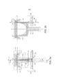
[0029] A presente invenção será mais bem entendida graças à descrição detalhada que segue e aos desenhos anexos, que são dados como exemplos não limitantes das configurações da invenção, onde: a Figura 1 ilustra um princípio básico de extração centrífuga; as Figuras 2a e 2b ilustram uma configuração da célula centrífuga com um porta-cápsula; as Figuras 3a, 3b, 3c ilustram uma configuração de um conjunto de cápsulas de acordo com a invenção; a Figura 4 ilustra uma configuração de um suporte de código, de acordo com a invenção; a Figura 5 ilustra uma posição alternativa da sequência na cápsula, em particular, quando colocada no lado de baixo do aro da cápsula, e a cápsula ajustada no porta-cápsula do dispositivo de extração; a Figura 6 ilustra por meio de um esquema uma bancada ótica usada para medir símbolos em uma configuração de cápsula de acordo com a invenção; a Figura 7 mostra um diagrama de refletividade difusa relativa dos símbolos de uma configuração de uma cápsula, de acordo com a invenção em função dos ângulos de fonte e detector; a Figura 8 mostra um diagrama do contraste entre símbolos de uma configuração de cápsula, de acordo com a invenção, em função dos ângulos de fonte e detector; a Figura 9 é um primeiro exemplo de um suporte de código oticamente legível ao longo de uma vista em seção transversal circunferencial na direção radial R no aro da cápsula da Figura 4;[0029] The present invention will be better understood thanks to the detailed description that follows and the accompanying drawings, which are given as non-limiting examples of embodiments of the invention, where: Figure 1 illustrates a basic principle of centrifugal extraction; Figures 2a and 2b illustrate a centrifugal cell configuration with a capsule holder; Figures 3a, 3b, 3c illustrate a configuration of a set of capsules according to the invention; Figure 4 illustrates a configuration of a code carrier according to the invention; Figure 5 illustrates an alternative position of the sequence in the capsule, in particular, when placed on the underside of the capsule rim, and the capsule fitted in the capsule holder of the extraction device; Figure 6 schematically illustrates an optical bench used to measure symbols in a capsule configuration in accordance with the invention; Figure 7 shows a diagram of relative diffuse reflectivity of symbols of a configuration of a capsule, according to the invention as a function of source and detector angles; Figure 8 shows a diagram of the contrast between symbols of a capsule configuration, according to the invention, as a function of source and detector angles; Figure 9 is a first example of an optically readable code carrier along a circumferential cross-sectional view in the radial direction R on the rim of the capsule of Figure 4;
[0030] A Figura 10 é um segundo exemplo de um suporte decódigo oticamente legível ao longo de uma vista em seção transversal circunferencial na direção radial R no aro da cápsula da Figura 4;[0030] Figure 10 is a second example of an optically readable code holder along a circumferential cross-sectional view in the radial direction R on the rim of the capsule of Figure 4;
[0031] As Figuras 11 a 13 ilustram representações gráficas damedida de refletividade em % respectivamente para suportes de código legíveis oticamente, de acordo com a invenção e para outro suporte de código comparativo.[0031] Figures 11 to 13 illustrate graphical representations of the reflectivity measure in % respectively for optically readable code carriers according to the invention and for other comparative code carriers.
[0032] A Figura 1 ilustra um exemplo de um sistema depreparação de bebida 1 como descrito em WO2010/026053, na qual a cápsula da invenção pode ser usada.[0032] Figure 1 illustrates an example of a
[0033] A unidade centrífuga 2 compreende uma célula centrífuga 3para exercer uma força centrífuga sobre o ingrediente da bebida e líquido contidos na cápsula. A célula 3 pode compreender um porta- cápsula e uma cápsula recebida neste. A unidade centrífuga é conectada a um meio acionador 5, que pode ser um motor rotativo, por exemplo. A unidade centrífuga compreende uma parte de coleta e saída 35. Um receptáculo 48 pode ficar sob a saída para coletar a bebida extraída. O sistema adicionalmente compreende um meio de suprimento de líquido, por exemplo, um reservatório de água 6 e circuito de fluído 4. Um meio de aquecimento 31 também pode ser provido no reservatório ou ao longo do circuito de fluído. O meio de suprimento de líquido também pode compreender adicionalmente uma bomba 7, conectada ao reservatório. Um meio restritor de fluxo 19 é provido para restringir o fluxo do líquido centrifugado, que sai da cápsula. O sistema, adicionalmente, pode compreender um medidor de fluxo, tal como uma turbina de medição de fluído 8, para prover controle da taxa de fluxo da água suprida na célula 3. O contador 11 pode ser conectado à turbina de medição de fluxo 8 para permitir analisar os dados de impulso gerados 10. Os dados analisados, então, são transferidos para o processador 12. Por conseguinte, a taxa de fluxo real exata do líquido dentro do circuito de fluído 4 pode ser calculada em tempo real. Uma interface de usuário 13 pode ser provida para permitir que o usuário insira informações transmitidas na unidade de controle 9. Características adicionais do sistema podem ser vistas em WO2010/026053.[0033] The
[0034] As Figuras 3a 3b, 3c se relacionam a uma configuração deum conjunto de cápsulas 2A, 2B, 2C. As cápsulas preferivelmente compreendem corpo 22, aro 23, e um membro de parede superior e tampa 24. A tampa 24 pode ser uma membrana perfurável ou parede de abertura. Onde, a tampa 24 e corpo 22 formam um envoltório i.e., que forma o compartimento de ingrediente 25. Como mostrado nas figuras, a tampa 24 preferivelmente é conectada a uma porção anular interna R do aro 23, preferivelmente tendo entre 1 e 5 mm.[0034] Figures 3a 3b, 3c relate to a configuration of a set of
[0035] O aro não precisa estar necessariamente na formailustrada. O aro pode ser ligeiramente curvado. O aro 23 das cápsulas preferivelmente se estende para fora na direção essencialmente perpendicular (como ilustrado) ou ligeiramente inclinada (se curvada, como mencionado) em relação ao eixo geométrico de rotação Z da cápsula. Com que, o eixo de rotação Z representa o eixo de rotação durante a centrifugação da cápsula no dispositivo de infusão, e, em particular, idêntico ao eixo de rotação Z do porta-cápsula 32 durante centrifugação da cápsula no dispositivo de infusão.[0035] The rim does not necessarily have to be in the shape shown. The rim can be slightly curved. The
[0036] Deve ser entendido que a configuração mostrada constituiapenas uma configuração exemplar, e as cápsulas, em particular, o corpo de cápsula 22, podem ter outras configurações.[0036] It should be understood that the configuration shown constitutes only an exemplary configuration, and the capsules, in particular the
[0037] O corpo 22 da respectiva cápsula tem uma porção convexaúnica 25a, 25b, 25c de profundidade variável, respectivamente d1, d2, d3. Onde, as porções 25a, 25b 25c também podem ser truncadas ou parcialmente cilíndricas.[0037] The
[0038] Assim, as cápsulas 2A, 2B, 2C preferivelmentecompreendem diferentes volumes, mas preferivelmente o mesmo diâmetro de inserção D. A cápsula da Figura 3a mostra uma cápsula de pequeno volume 2A enquanto a cápsula das Figuras 3b e 3c mostram cápsulas maiores respectivamente 2B e 2C. O diâmetro de inserção D é determinado na linha da interseção entre a superfície inferior do aro 23 e a porção superior do corpo 22. No entanto, pode haver outros diâmetros de referência da cápsula no dispositivo.[0038] Thus,
[0039] A cápsula pequena 2A preferivelmente contém umaquantidade de ingrediente de extração, por exemplo, café moído, menor que a quantidade das cápsulas média e grande 2B e 2C. A cápsula pequena 2A fornece uma um café curto de 10 e 60 ml com uma quantidade de café moído entre 4 e 8 gramas. A cápsula média 2B fornece um café médio por exemplo, 60 e 120 ml, enquanto a cápsula grande 2C fornece um café longo por exemplo, com 120 a 500 ml. Ademais, a cápsula de café médio contém uma quantidade de café moído entre 6 e 15 gramas e a cápsula de café longo 2C uma quantidade de café moído entre 8 e 30 gramas.[0039] Small capsule 2A preferably contains an amount of extraction ingredient, eg ground coffee, less than the amount of medium and
[0040] Em adição, as cápsulas no conjunto de acordo com ainvenção podem conter diferentes misturas de café torrado e moído de diversas origens e/ou tendo diferentes características de tostamento e moagem.[0040] In addition, the capsules in the set according to the invention may contain different blends of roasted and ground coffee from different origins and/or having different roasting and grinding characteristics.
[0041] A cápsula é projetada para girar em torno do eixo geométrico Z. O eixo geométrico Z atravessa perpendicularmente o centro da tampa com forma de disco. O eixo Z sai no centro da base do corpo. O eixo geométrico Z ajuda a definir a noção de circunferência, que é uma trajetória circular localizada na cápsula, e tendo o eixo X de referência. Esta circunferência pode ficar na tampa, por exemplo, tampa ou na parte do corpo, tal como no aro em forma de flange. A tampa pode ser impermeável a líquidos, antes da inserção no dispositivo ou pode ser permeável a líquidos, por meio de pequenas aberturas ou poros fornecidas no centro e /ou periferia da tampa.[0041] The capsule is designed to rotate around the Z axis. The Z axis perpendicularly crosses the center of the disk-shaped lid. The Z axis comes out at the center of the base of the body. The geometric axis Z helps to define the notion of circumference, which is a circular path located in the capsule, and having the X axis as a reference. This circumference can be on the cap, for example, the cap, or on the body part, such as the flange-shaped rim. The cap may be liquid impermeable prior to insertion into the device or it may be liquid permeable through small openings or pores provided in the center and/or periphery of the cap.
[0042] A seguir, a superfície inferior do aro 23 é a seção do aro 23que fica fora do envoltório formado pelo corpo e tampa, e sendo visível quando a cápsula é orientada para o lado onde seu corpo é visível.[0042] Next, the lower surface of the
[0043] Características adicionais das cápsulas ou conjunto decápsulas podem ser encontradas nos documentos WO 2011/0069830, WO 2010/0066705, ou WO2011/0092301.[0043] Additional features of the capsules or set of capsules can be found in WO 2011/0069830 , WO 2010/0066705 , or WO2011/0092301 .
[0044] Uma configuração da célula centrífuga 3 com um porta-cápsula 32 é ilustrada nas Figuras 2a e 2b. O porta-cápsula 32 geralmente tem uma abertura superior para inserir a cápsula e base para fechar o receptáculo. A abertura tem um diâmetro ligeiramente maior que aqueles do corpo 22 da cápsula. O contorno da abertura se ajusta ao contorno do aro 23 da cápsula configurada para inclinar o aro da abertura, quando cápsula é inserida. Em consequência, o aro 23 da cápsula é colocado, pelo menos parcialmente, sobre uma parte receptora 34 do porta-cápsula 32. A base inferior tem um eixo cilíndrico 33 afixado perpendicularmente ao centro da face externa da base. O porta-cápsula 32 gira em torno do eixo geométrico central Z do eixo 33.[0044] A configuration of the centrifugal cell 3 with a
[0045] Um arranjo de leitura ótica 100 também está representadonas Figuras 2a e 2b. O arranjo de leitura ótica 100 é configurado para fornecer um sinal de saída compreendendo informações relativas ao nível de refletividade de uma superfície da superfície inferior do aro 23 da cápsula se estendendo na parte receptora 34 do porta-cápsula 32. O arranjo de leitura ótica é configurado para realizar medições óticas da superfície da superfície inferior do aro 23 através da porta-cápsula 32, mais particularmente através de uma parede lateral de um porta- cápsula cilíndrico ou cônico 32. Alternativamente, o sinal de saída pode conter uma informação diferencial, por exemplo, uma diferença de refletividade ao longo do tempo ou informação de contraste. O sinal de saída pode ser analógico, por exemplo, sinal de voltagem variando com informações medidas ao longo do tempo. O sinal de saída pode ser digital, por exemplo, um sinal binário, compreendendo dados numéricos das informações medidas ao longo do tempo.[0045] An
[0046] Na configuração das Figuras 2a e 2b, o arranjo de leitura100 compreende um emissor de luz 103 para emitir um feixe de luz de fonte 105a e receptor de luz 102 para receber o feixe de luz refletido 105b.[0046] In the configuration of Figures 2a and 2b, the
[0047] Tipicamente, o emissor de luz 103 é um diodo emissor deluz ou diodo laser, emitindo luz infravermelha, e, mais particularmente, uma luz com um comprimento de onda de 850 nm. Tipicamente, o receptor de luz 103 é um fotodiodo adaptado para converter um feixe de luz recebido em sinal de corrente ou voltagem.[0047] Typically, the
[0048] O arranjo de leitura 100 compreende também um meio deprocessamento 106 incluindo uma placa de circuito impresso incorporando um processador, amplificador de sinal de sensor, filtros de sinal, e circuitagem para acoplar o citado meio de processamento 106 ao emissor de luz 103, receptor de luz 102, e unidade de controle 9 da máquina.[0048] The
[0049] O emissor de luz 103, receptor de luz 102, e meio deprocessamento 106 são mantidos em uma posição fixa por um suporte 101, rigidamente fixado com respeito ao quadro da máquina. O arranjo de leitura 100 fica em uma posição durante o processo de extração, e não é colocado em rotação, ao contrário do porta-cápsula 32.[0049] The
[0050] Em particular, o emissor de luz 103 é disposto de modo queo feixe de luz de fonte 105a fique geralmente orientado ao longo de uma linha L, cruzando no ponto fixo F, o plano compreendendo a parte receptora 34 do porta-cápsula 32, o citado plano P tendo uma linha normal N passando através do ponto F.[0050] In particular, the
[0051] O ponto fixo F determina a posição absoluta no espaçoonde os feixes de luz de fonte 105a devem atingir uma superfície refletiva, onde a posição do ponto fixo F se mantém inalterado quando porta-cápsula é colocado em rotação. O arranjo de leitura pode compreender um meio focalizador 104 usando, por exemplo, furos, lentes, e/ou prismas, para fazer o feixe de luz de fonte 105 convergir mais eficientemente sobre o porta-cápsula 32. Em particular, o feixe de luz de fonte 105 pode ser focalizado de modo a iluminar um disco centrado adequadamente no ponto fixo F tendo um diâmetro d.[0051] Fixed point F determines the absolute position in space where light beams from
[0052] O arranjo de leitura 100 é configurado, de modo que oângulo θE entre a linha L e a linha normal N fique entre 2° e 10°, em particular, entre 4° e 5°, como mostrado na Figura 2a. Em consequência, quando uma superfície refletiva é disposta no ponto F, o feixe de luz refletido 105b é geralmente orientado ao longo da linha L' cruzando o ponto fixo F o ângulo θE entre linhas L’ e N sendo compreendido entre 2° e 10°, em particular, entre 4° e 5°, como mostrado na Figura 2a. O receptor de luz 102 é disposto no suporte 101 de modo a colher pelo menos parcialmente o feixe de luz refletido 105b geralmente orientado ao longo da linha L’. O meio focalizador 104 pode também ser disposto para fazer o feixe de luz refletido 105b se concentrar mais eficientemente no receptor 102. Na configuração ilustrada nas Figuras 2a, 2b, o ponto F e as linhas L e L’ sãocoplanares. Em outra configuração, o ponto F e as linhas L e L’ não são coplanares: por exemplo, o plano passando através do ponto F e linha L e o plano passando através do ponto F e linha L’ são posicionados em 90° eliminando reflexão direta, e provendo um sistema de leitura mais robusto com menos ruído.[0052] The
[0053] O porta-cápsula 32 é adaptado para permitir a transmissãoparcial do feixe de luz de fonte 105a ao longo da linha L para o ponto F. Por exemplo, a parede lateral formando uma cavidade cilíndrica ou cônica do porta-cápsula é configurada para ser não-opaca a luz infravermelha. A citada parede lateral pode ser feita de um material plástico translúcido à luz infravermelha tendo superfícies de entrada que permitem penetração da luz infravermelha.[0053] The
[0054] Em consequência, quando a cápsula é posicionada noporta-cápsula 32, o feixe de luz 105 atinge a parte da base do aro da citada cápsula no ponto F antes de formar o feixe de luz refletido 105b. Nesta configuração, o feixe de luz refletido 105b passa através da parede do porta-cápsula em direção ao receptor 102.[0054] Consequently, when the capsule is positioned in the
[0055] A seção da superfície inferior do aro 23 de uma cápsulaposicionada no porta-cápsula 32 iluminada no ponto F por um feixe de luz de fonte 105, muda ao longo do tempo, somente quando o porta- cápsula 34 for colocado em rotação. Assim, uma rotação completa do porta-cápsula 32 é requerida para o feixe de luz da fonte 105 iluminar toda a seção anular da superfície inferior do aro.[0055] The section of the lower surface of the
[0056] O sinal de saída pode ser computado ou gerado medindotempo, intensidade do feixe de luz refletido, e possivelmente comparando sua intensidade àquela do feixe de luz de fonte. O sinal de saída pode ser computado ou gerado determinando a variação ao longo do tempo da intensidade do feixe de luz refletido.[0056] The output signal can be computed or generated by measuring time, intensity of the reflected light beam, and possibly comparing its intensity to that of the source light beam. The output signal can be computed or generated by determining the variation over time in the intensity of the reflected light beam.
[0057] A cápsula de acordo com a invenção compreende pelomenos um suporte de código oticamente legível. O suporte de código pode estar na presente parte do aro tipo flange. Símbolos são representados no suporte de código oticamente legível. Os símbolos são dispostos em pelo menos uma sequência, a citada sequência codifica um conjunto de informações relativas à cápsula. Tipicamente, cada símbolo corresponde a um valor binário específico, um primeiro símbolo pode representar valor binário ‘0’, enquanto um segundo símbolo pode representar um valor binário ‘1’.[0057] The capsule according to the invention comprises at least one optically readable code carrier. The code holder may be on the present flange-like rim part. Symbols are represented in optically readable code support. The symbols are arranged in at least one sequence, said sequence encoding a set of information relating to the capsule. Typically, each symbol corresponds to a specific binary value, a first symbol may represent binary value '0', while a second symbol may represent binary value '1'.
[0058] Em particular, o conjunto de informações de pelo menosuma das sequências pode compreender informações para reconhecer um tipo associado à cápsula, e/ou uma combinação de itens da seguinte lista:[0058] In particular, the information set of at least one of the sequences may comprise information to recognize a type associated with the capsule, and/or a combination of items from the following list:
[0059] Informações relativas aos parâmetros para preparar umabebida com a cápsula, tal como os valores ótimos de rotação, temperatura da água que entra na cápsula, temperatura do coletor da bebida fora da cápsula, taxas de fluxo da água que entra na cápsula, sequência de operações durante o processo de preparação etc.[0059] Information regarding the parameters for preparing a beverage with the capsule, such as the optimal rotation values, temperature of the water entering the capsule, temperature of the beverage collector outside the capsule, flow rates of the water entering the capsule, sequence of operations during the preparation process, etc.
[0060] Informações para recuperar localmente e remotamenteparâmetros para preparar bebida com a cápsula, por exemplo, identificador que permita reconhecer o tipo da cápsula; e[0060] Information to retrieve locally and remotely parameters to prepare beverage with the capsule, for example, identifier that allows recognizing the type of capsule; and
[0061] Informações relativas à fabricação da cápsula, tal comoidentificador de lote, data de produção, data recomendada de consumo, data de validade;[0061] Information relating to the manufacture of the capsule, such as batch identifier, production date, recommended consumption date, expiration date;
[0062] Informação para recuperar localmente e/ou remotamenteinformações relativas à fabricação da cápsula.[0062] Information to retrieve locally and/or remotely information relating to the manufacture of the capsule.
[0063] Cada conjunto de informações de pelo menos uma dassequências pode compreender informações redundantes. Assim, uma verificação de erro pode ser realizada por comparação. Isto também melhora por probabilidade a condição de se conseguir uma leitura bem sucedida da sequência se algumas partes da sequência forem ilegíveis. O conjunto de informações de informações de pelo menos uma das sequências também pode compreender informações para detectar e/ou corrigir erros no citado conjunto de informações. Informações para detectar erros podem compreender códigos de repetição, bits de paridade, verificação de soma, verificações cíclicas de redundância, dados de função hash criptográfica, etc.. Informações para corrigir erros podem compreender códigos de correção de erro, códigos de correção de informação avançada, e, em particular, códigos de convolução ou códigos de bloco.[0063] Each set of information from at least one of the sequences can comprise redundant information. Thus, an error check can be performed by comparison. This also improves by probability the condition of achieving a successful read of the sequence if some parts of the sequence are unreadable. The information set of information of at least one of the sequences may also comprise information for detecting and/or correcting errors in said set of information. Information to detect errors may comprise repeat codes, parity bits, checksum, cyclic redundancy checks, cryptographic hash function data, etc. Information to correct errors may comprise error correction codes, advanced information correction codes , and in particular convolution codes or block codes.
[0064] Os símbolos dispostos em sequência são usados pararepresentar dados, conduzindo o conjunto de informações relativas à cápsula. Por exemplo, cada sequência pode representar um número de bits. Cada símbolo pode codificar um de diversos bits binários. Os dados também podem ser representados pela transição entre símbolos. Os símbolos podem ser dispostos na sequência, usando um esquema de modulação, por exemplo, um esquema de codificação de linha, tal como código Manchester.[0064] The symbols arranged in sequence are used to represent data, leading the set of information related to the capsule. For example, each string can represent a number of bits. Each symbol can encode one of several binary bits. Data can also be represented by the transition between symbols. The symbols may be arranged in sequence using a modulation scheme, for example a line encoding scheme such as Manchester code.
[0065] Cada símbolo pode ser impresso e/ou gravado em relevo. Aforma dos símbolos pode ser escolhida na seguinte lista não- exaustiva: segmentos em arco, segmentos individualmente retilíneos, que se estendem ao longo de pelo menos parte da seção, pontos, polígonos, formas geométricas.[0065] Each symbol can be printed and/or embossed. The shape of the symbols can be chosen from the following non-exhaustive list: arc segments, individually rectilinear segments, which extend along at least part of the section, points, polygons, geometric shapes.
[0066] Em uma configuração, cada sequência tem comprimentofixo igual, e, mais particularmente, o mesmo número fixo de símbolos. A estrutura e/ou modelo de sequência é conhecida e pode facilitar o reconhecimento de cada sequência pelo arranjo de leitura.[0066] In one configuration, each string is of equal fixed length, and more particularly, the same fixed number of symbols. The structure and/or pattern of the sequence is known and can facilitate recognition of each sequence by the reading frame.
[0067] Em uma configuração, pelo menos um símbolo depreâmbulo é representado na seção, de modo a permitir a determinação de posição de início e/ou fim na seção de cada sequência. O símbolo de preâmbulo é escolhido para ser identificado separadamente de outros símbolos. Pode haver uma diferente forma e/ou características físicas diferentes em comparação com outros símbolos. Duas sequências adjacentes podem ter um símbolo de preâmbulo comum, representando o fim de uma sequência e o início de outra sequência.[0067] In one configuration, at least one preamble symbol is represented in the section, in order to allow the determination of start and/or end position in the section of each sequence. The preamble symbol is chosen to be identified separately from other symbols. There may be a different shape and/or different physical characteristics compared to other symbols. Two adjacent sequences may have a common preamble symbol, representing the end of one sequence and the beginning of another sequence.
[0068] Em uma configuração, pelo menos uma das sequênciascompreende símbolos definindo uma sequência de preâmbulo de modo a permitir determinar, em uma posição dos símbolos no citado código de sequência, o conjunto de informações relativo à cápsula. Os símbolos que definem o preâmbulo podem codificar uma sequência reservada conhecida de bits, por exemplo ‘10101010’.[0068] In one configuration, at least one of the sequences comprises symbols defining a preamble sequence in order to make it possible to determine, in a position of the symbols in said sequence code, the set of information related to the capsule. The symbols defining the preamble may encode a known reserved sequence of bits, for example '10101010'.
[0069] Em uma configuração, os símbolos e/ou sequências depreâmbulo compreendem informações para autenticar o conjunto de informações, por exemplo, um código hash em toda a circunferência de uma assinatura criptográfica.[0069] In one configuration, the preamble symbols and/or sequences comprise information to authenticate the set of information, for example, a hash code around the circumference of a cryptographic signature.
[0070] Os símbolos são distribuídos adequadamente em pelomenos 1/8 da circunferência do suporte anular, preferivelmente em toda a circunferência do suporte anular. O código pode compreender sucessivos segmentos em arco. Os símbolos também podem compreender segmentos sucessivos que são individualmente retilíneos, mas se estendem ao longo de pelo menos parte da circunferência.[0070] The symbols are properly distributed over at least 1/8 of the circumference of the annular support, preferably the entire circumference of the annular support. The code may comprise successive arc segments. The symbols may also comprise successive segments that are individually rectilinear but extend along at least part of the circumference.
[0071] A sequência é preferivelmente repetida ao longo dacircunferência para garantir uma leitura confiável. A sequência é repetida pelo menos duas vezes na circunferência. Preferivelmente, a sequência é repetida três a seis vezes na circunferência. A repetição da sequência significa que a mesma sequência é duplicada, e as sucessivas sequências são posicionadas em série ao longo da circunferência, de modo que em uma rotação de 360° da cápsula, a mesma sequência seja detectada ou lida mais que uma vez.[0071] The sequence is preferably repeated along the circumference to ensure reliable reading. The sequence is repeated at least twice on the circle. Preferably, the sequence is repeated three to six times around the circumference. Sequence repetition means that the same sequence is duplicated, and successive sequences are positioned in series along the circumference, so that in a 360° rotation of the capsule, the same sequence is detected or read more than once.
[0072] Referindo-se à Figura 4, uma configuração 30a de umsuporte de código é ilustrada. O suporte de código 60a ocupa a largura definida do aro 23 da cápsula. O aro 23 da cápsula pode compreender essencialmente uma porção anular interna, formando o suporte 60a e uma porção enrolada externa (não codificada). No entanto, pode ser que a largura inteira do aro seja ocupada pelo suporte 60a, em particular, a superfície inferior do aro pode ser feita substancialmente plana. Esta localização é particularmente vantajosa, uma vez que provê uma grande área para os símbolos, e menos tendência a danos causados pelo módulo de processamento, e, em particular, pela placa piramidal e a projeções dos ingredientes. Em consequência, tanto a quantidade de informações codificadas e confiabilidade das leituras são ambas melhoradas. Nesta configuração, o suporte de código 60a compreende 160 símbolos, cada símbolo compreendendo 1 bit de informação. Os símbolos são contíguos e cada símbolo tem um comprimento de arco de 2,25°.[0072] Referring to Figure 4, a configuration 30a of a code holder is illustrated. The
[0073] Referindo-se à Figura 5, a configuração 60b do suporte decódigo é ilustrada em uma vista plana. O suporte de código 60b é adaptado para ser associado ou integrado a uma, cápsula de modo que gira coma rotação da cápsula em torno de seu eixo geométrico Z pela ação da unidade centrífuga 2. A seção receptora da cápsula é a superfície inferior do aro 23 da cápsula. Como ilustrado na Figura 5, o suporte de código pode ser um anel, tendo uma parte circunferencial, da qual a pelo menos uma sequência dos símbolos é repetida de modo que o usuário possa posicioná-lo na circunferência da cápsula antes de introduzi-lo na unidade de infusão da máquina de bebida. Em consequência, a cápsula sem um meio incorporado para armazenar informações, pode ser modificada, montando o suporte de modo a adicionar informações. Quando o suporte constitui parte separada, o suporte pode ser simplesmente adicionado à cápsula sem qualquer meio de fixação adicional, o usuário garantindo que o suporte está corretamente posicionado, ao entrar na unidade de infusão ou as formas e dimensões do suporte impedem que o suporte se mova em relação à cápsula, uma vez montado. O suporte de código 60b também pode compreender meios de fixação adicionais, para fixar rigidamente o citado elemento à seção receptora da cápsula, tal como cola ou meios mecânicos, de modo a ajudar que o suporte fique fixo em relação à cápsula, uma vez montado. Ademais, como mencionado, o suporte de código 60b também pode ser parte integrante do próprio aro, tal como integrado à estrutura da cápsula.[0073] Referring to Figure 5, the
[0074] Cada símbolo é adaptado para ser medido pelo arranjo de leitura 100, quando a cápsula estiver posicionada no porta-cápsula e quando o citado símbolo estiver alinhado com a feixe de luz de fonte 105a no ponto F. Em particular, cada símbolo diferente tem um nível de refletividade do feixe de luz de fonte 105a que varia com o valor do citado símbolo. Cada símbolo tem propriedades refletivas e/ou absorventes diferentes do feixe de luz da fonte 105a.[0074] Each symbol is adapted to be measured by the
[0075] Uma vez que o arranjo de leitura 100 é adaptado paramedir apenas características da seção iluminada do suporte de código, a cápsula deve girar pela ação do meio acionador, até o feixe de luz da fonte iluminar todos símbolos no código. Tipicamente, a velocidade de leitura do código pode ficar entre 0,1 e 2000 rpm.[0075] Since the
[0076] As características refletivas do suporte de código dainvenção são determinadas em condições de laboratório definidas. Em particular, um primeiro e segundo símbolos de uma configuração de uma cápsula, que são adequados para serem lidos confiavelmente pelo arranjo de leitura 100, são medidos independentemente, com a bancada ótica representada na Figura 6. As medições goniométricas de reflexão difusa dos citados símbolos na cápsula estão mostradas nas Figuras 7 (intensidade refletida de cada símbolo) e 8 (contraste entre símbolos).[0076] The reflective characteristics of the code support of the invention are determined under defined laboratory conditions. In particular, first and second symbols of a capsule configuration, which are suitable to be read reliably by the
[0077] A seguir, o primeiro símbolo é mais refletivo que o segundosímbolo. O ajuste para medição da intensidade relativa refletida difusa de cada símbolo é formado de modo a ser capaz de modificar independentemente o ângulo θ da fonte de luz e o ângulo θ’ de um detector de luz. O detector provido em uma fibra ótica nua conectada a um medidor de potência colado a uma ponta mecânica muito fina, que é fixada no braço de um detector motorizado. Para todas medições, o ângulo α entre planos de fonte e detector é igual a Φ= 90°. A fonte de luz é um diodo laser emitindo luz com um comprimento de onda À= 830 nm.[0077] Next, the first symbol is more reflective than the second symbol. The setting for measuring the relative diffuse reflected intensity of each symbol is formed so as to be able to independently modify the angle θ of the light source and the angle θ' of a light detector. The detector is provided in a bare optical fiber connected to a power meter glued to a very fine mechanical tip, which is fixed to the arm of a motorized detector. For all measurements, the angle α between source and detector planes is equal to Φ= 90°. The light source is a laser diode emitting light with a wavelength of A = 830 nm.
[0078] O diagrama da Figura 7 mostra uma refletividade difusarelativa (eixo geométrico 210) dos símbolos da cápsula em função do ângulo detector θ’ (eixo geométrico 200). Uma intensidade de referência EREF de refletividade é medida para o primeiro símbolo com referência ao ângulo do detector ajustado em 0o e ângulo de fonte em 5°. A refletividade difusa relativa de cada símbolo é calculada com respeito à intensidade de referência EREF. As curvas 220a, 230a, 240a mostram respectivamente a refletividade difusa relativa do primeiro símbolo em três ângulos de fonte diferentes 0o, 5° 10°. As curvas 220b, 230b, 240b mostram respectivamente a refletividade difusa relativa do segundo símbolo em três ângulos de fonte diferentes θ = 0o, 5° 10°.[0078] The diagram of Figure 7 shows a relative diffuse reflectivity (geometric axis 210) of the capsule symbols as a function of the detector angle θ' (geometric axis 200). An EREF reference intensity of reflectivity is measured for the first symbol with reference to the detector angle set to 0° and source angle to 5°. The relative diffuse reflectivity of each symbol is calculated with respect to the reference intensity EREF.
[0079] A refletividade difusa relativa representa pelo menos 60%da intensidade de referência EREF para qualquer valor de quando de detector θ’ fica entre 3° e 6° e para qualquer valor do quando da fonte θ entre 0o e 10°. Em particular, a refletividade difusa relativa representa pelo menos 72% da intensidade de referência EREF para qualquer valor do ângulo de detector θ’ fica entre 2,5o e 4,4°, e para qualquer valor do ângulo de fonte θ entre 0o e 10°.[0079] The relative diffuse reflectivity represents at least 60% of the EREF reference intensity for any detector when value θ' is between 3° and 6° and for any value of source when θ between 0° and 10°. In particular, the relative diffuse reflectivity represents at least 72% of the EREF reference intensity for any value of detector angle θ' between 2.5° and 4.4°, and for any value of source angle θ between 0° and 10 °.
[0080] O diagrama na Figura 8 mostra o contraste ótico (eixo 310)entre primeiro símbolo e segundo símbolo em função do ângulo de íl - í2 detector θ (eixo geométrico 300). O contraste ótico é dado por :i + :2, onde, i1 e i2 representam, respectivamente, a intensidade refletida pelo primeiro símbolo e segundo símbolo respectivamente ao detector na mesma dada configuração dos ângulos θ e θ’. As curvas 320, 330, 340 350 mostram respectivamente em quatro ângulos de fontediferentes 0o, 5°, 10°, 15°, o citado contraste ótico. O valor de contraste mais baixo é em qualquer caso maior que 65%, que provê um processamento de sinal confiável. Em particular, o contraste ótico é maior que 80% para qualquer valor do ângulo de detector θ’ fica entre 2,5° e 4,4° e para qualquer valor de fonte θ entre 10° e 15°. Em particular, o contraste ótico é maior que 75% para qualquer valor do ângulo de detector θ’ maior que 6° e para qualquer valor de ângulo de fonte θ entre 0oe 15°.[0080] The diagram in Figure 8 shows the optical contrast (axis 310) between first symbol and second symbol as a function of angle of l - l2 detector θ (geometric axis 300). The optical contrast is given by :i + :2, where, i1 and i2 represent, respectively, the intensity reflected by the first symbol and second symbol respectively to the detector in the same given configuration of angles θ and θ'. The
[0081] A Figura 9 ilustra um modo preferido de suporte de códigooticamente legível 30 da invenção, em uma vista circunferencial em seção transversal da Figura 4. O suporte de código 30 inclui lado (externo) legível A e lado (interno) não legível B. No lado legível A, o suporte compreende sucessivas superfícies refletivas de luz 400 a 403, e superfícies absorvente de luz 410-414. As superfícies absorventes de luz 410- 414 são formadas por uma estrutura base 500 que compreende diversas camadas sobrepostas, onde as superfícies absorventes 400- 403 são formadas sobrepondo a estrutura base nas áreas circunferenciais locais, porções discretas descontínuas de materiais absorventes de luz, preferivelmente porções discretas de camadas de tinta 528 aplicadas sobre a estrutura base. A estrutura base inclui uma camada preferivelmente monolítica de metal 510, preferivelmente alumínio (ou liga de alumínio), sobre a qual é aplicado um revestimento de primer polimérico transparente 515, que preferivelmente é feito de isocianato ou poliéster. A espessura do metal, por exemplo, camada de alumínio, pode ser um fator determinante para formação do suporte em uma estrutura de contenção da cápsula (por exemplo, corpo e aro). Por razões de formação, a camada de alumínio preferivelmente fica entre 40 e 250 mícrons, o mais preferível entre 50 e 150 mícrons. Dentro destas faixas, a espessura do alumínio também pode prover propriedades de barreira de gás, para manter fresco o ingrediente na cápsula, em particular, quando a cápsula adicionalmente compreende membrana de barreira de gás selada no aro.[0081] Figure 9 illustrates a preferred mode of optically
[0082] O suporte de código pode ser formado a partir de umlaminado deformado para formar o aro 22 e corpo 23 da cápsula (Figuras 3a e 3b). Neste caso, o laminado tem composição da estrutura base 50 é impresso com as porções de tinta absorventes de luz 400-403 na configuração plana antes da operação de formação da cápsula (por exemplo, corpo e aro). A impressão das porções de tinta, assim, deve levar em conta a subsequente deformação do laminado, de modo a permitir um posicionamento preciso das superfícies codificadas. O tipo de tinta pode ser uma tinta mono- ou bi- componente, baseada em PVC ou tintas sem PVC. A tinta preta é preferida porque provê uma refletividade mais baixa e contraste mais alto que as tintas coloridas. No entanto, as porções de tinta preta podem ser substituídas por porções de tinta colorida equivalentes, preferivelmente tintas escuras ou opacas. A tinta pode compreender, por exemplo, 50 a 80% em peso de pigmentos coloridos.[0082] The code holder can be formed from a deformed laminate to form the
[0083] Preferivelmente, a camada metálica é alumínio e tem umaespessura entre 6 e 250 mícrons. O primer permite compensar a rugosidade da camada metálica (i.e., de alumínio). Isto também melhora a adesão das tintas na camada metálica, em particular, alumínio. O primer deve permanecer relativamente fino para diminuir a difusão do feixe de luz. Preferivelmente, a espessura do primer deve estar entre 0,1 e 5 mícrons, o mais preferível entre 0,1 e 3 mícrons. A densidade do primer preferivelmente é compreendida entre 2 e 3 g/m2, por exemplo, cerca de 2,5 g/m2.[0083] Preferably, the metallic layer is aluminum and has a thickness between 6 and 250 microns. The primer makes it possible to compensate for the roughness of the metallic (i.e. aluminum) layer. This also improves the adhesion of the inks to the metallic layer, in particular aluminum. The primer must remain relatively thin to lessen the scattering of the light beam. Preferably, the thickness of the primer should be between 0.1 and 5 microns, most preferably between 0.1 and 3 microns. The density of the primer is preferably comprised between 2 and 3 g/
[0084] Opcionalmente, a estrutura base pode compreendercamadas adicionais no lado não legível, preferivelmente uma camada polimérica, tal como de polipropileno ou polietileno, e uma camada de adesivo para colar a camada polimérica na camada metálica 510 ou laca de selagem quente permitindo selar a tampa ou membrana do aro da cápsula ou laca ou verniz protetivo interno. O suporte, como definido, pode se parte integrante da cápsula por exemplo, aro e corpo tipo flange.[0084] Optionally, the base structure may comprise additional layers on the non-readable side, preferably a polymeric layer, such as polypropylene or polyethylene, and a layer of adhesive for gluing the polymeric layer to the
[0085] Uma estrutura base preferida de acordo com o modo daFigura 9, compreende respectivamente do lado B para o lado A do suporte, uma camada de polipropileno de 30 mícrons, um adesivo, uma camada de alumínio de 90 mícrons, uma camada poliéster de 2 mícrons e densidade de 2,5 g/m2, e porções de tinta preta de 1 mícron. Em um modo alternativo, as camadas de primer são substituídas por laca com espessura de 5 mícrons, preferivelmente densidade de 5,5 g/m2 e contendo 5% em peso de pigmentos metálicos.[0085] A preferred base structure according to the method of Figure 9, comprises respectively from side B to side A of the support, a 30 micron polypropylene layer, an adhesive, a 90 micron aluminum layer, a polyester layer of 2 microns and 2.5 g/m2 density, and 1 micron black ink portions. In an alternative mode, the primer layers are replaced by lacquer with a thickness of 5 microns, preferably density of 5.5 g/
[0086] A Figura 10 relaciona-se a outro modo de suporte de código 30 da invenção. Neste caso, a estrutura base compreende a laca 530 substituindo o primer 535 da Figura 9. A laca é uma camada polimérica incorporando pigmentos metálicos 535, tais como pigmentos de alumínio, prata, ou cobre, ou misturas destes. A espessura da laca é maior, em alguma extensão, que a espessura do primer 510 da Figura 9, preferivelmente entre 3 e 8 mícrons, o mais preferível entre 5 e 8 mícrons. Os pigmentos metálicos permitem equilibrar a redução da refletividade da camada metálica com maior espessura do polímero. A laca também equilibra a rugosidade da camada metálica. Preferivelmente, a razão de pigmentos metálicos com a laca é pelo menos 1% em peso, mais preferivelmente compreendido entre 2 e 10% em peso.[0086] Figure 10 relates to another
[0087] Na presente invenção, a referência a metais específicosengloba as ligas possíveis dos mesmos, onde o metal representa o componente principal em peso, por exemplo, o alumínio compreende ligas de alumínio.[0087] In the present invention, the reference to specific metals encompasses the possible alloys thereof, where the metal represents the main component by weight, for example, aluminum comprises aluminum alloys.
[0088] Cápsulas compreendendo um suporte de código integradoforam testadas para avaliar o nível de refletividade do sinal (bit 1/ bit 0). Os testes foram realizados em uma configuração simplificada do dispositivo das Figuras 2a e 2b onde o porta-cápsula 32 foi removido, e substituído por uma placa de fixação transparente, fixando o aro da cápsula, e incluindo uma passagem de ar para os feixes de luz. O ângulo entre a trajetória de envio e a trajetória de recepção foi 8°, distribuído em 4° em cada lado do eixo geométrico normal N.Exemplo 1Código detectável com superfícies refletivas de luz pela estrutura base com laca colorida e superfícies absorventes de luz pelas porções de tinta sobrepostas[0088] Capsules comprising an embedded code holder were tested to assess the level of signal reflectivity (
[0089] O suporte compreendido de uma estrutura base refletivaformada de alumínio de 30 mícrons revestida de laca refletiva de alumínio de 5 mícrons e 5,5 g/m2. As superfícies refletivas receberam uma camada de tinta PVC preta de um mícron da Siegwerk. As superfícies refletivas foram produzidas pelas porções de tinta preta. A refletividade máxima medida para as superfícies refletivas (bit 1) foi 2,68%. A dispersão no bit 1 foi 1,32 %. A refletividade mínima medida na superfície absorvente (bit) foi 0,73%. A dispersão no bit 0 foi 0,48%. Os resultados estão ilustrados graficamente na Figura 11.Exemplo 2Código detectável com superfícies refletivas de luz pela estrutura base com primer sem cor e superfícies absorventes de luz pelas porções de tinta sobrepostas[0089] The support comprised of a reflective base frame formed of 30 micron aluminum coated with 5 micron, 5.5 g/m2 aluminum reflective lacquer. The reflective surfaces were coated with one-micron black PVC paint from Siegwerk. The reflective surfaces were produced by the black paint patches. The maximum reflectivity measured for the reflective surfaces (bit 1) was 2.68%. The dispersion in
[0090] A medição de refletividade foi realizada em uma cápsulavazia compreendendo um suporte de leitura ótica compreendendo uma estrutura base formando superfícies refletivas e porções de tinta formando superfícies absorventes. Para isto, a estrutura base era compreendida de lados B e A (legível) respectivamente camada de polipropileno de 30 mícrons, adesivo, camada de alumínio de 90 mícrons e um primer de poliéster de 2 mícrons e 2,5 g/m2 (densidade). Porções de bit descontínuas de tinta preta de 1 mícron da Siegwerk foram impressas na superfície do primer. O suporte foi formado por estampagem profunda em um corpo de cápsula, depois da impressão com tinta. As superfícies refletivas foram produzidas pela estrutura base (bit 1) e as superfícies absorventes (bit 0) foram produzidas pelas porções de tinta preta. A refletividade do suporte foi medida. Os resultados estão graficamente ilustrados na Figura 12. A refletividade máxima medida para as superfícies refletivas (bit 1) foi 5,71%. A dispersão no bit 1 foi 1,49%. A refletividade mínima medida para as superfície absorvente (bit 0) foi 0,87%. A dispersão no bit 0 foi 0,47%. Exemplo 3Código não detectável com superfícies refletivas de luz pela estrutura base e superfícies absorventes de luz pelas porções de tinta sobrepostas[0090] The reflectivity measurement was performed on an empty capsule comprising an optical readout support comprising a base structure forming reflective surfaces and ink portions forming absorbing surfaces. For this, the base structure was comprised of sides B and A (readable) respectively, a polypropylene layer of 30 microns, adhesive, aluminum layer of 90 microns and a polyester primer of 2 microns and 2.5 g/m2 (density) . Discontinuous bit portions of Siegwerk's 1-micron black ink were printed onto the primer surface. The support was formed by deep stamping a capsule body, after printing with ink. The reflective surfaces were produced by the base structure (bit 1) and the absorbent surfaces (bit 0) were produced by the black paint patches. The reflectivity of the support was measured. The results are graphically illustrated in Figure 12. The maximum reflectivity measured for the reflective surfaces (bit 1) was 5.71%. The dispersion in
[0091] A medição de refletividade foi realizada em uma cápsulavazia compreendendo um suporte de leitura ótica compreendendo uma estrutura base formando superfícies absorventes e porções de tinta formando superfícies refletivas. Para isto, uma camada suporte de alumínio foi revestida com laca preta de manta contínua com espessura de 5 mícrons. As superfícies refletivas foram produzidas por porções discretas de tinta com espessura de 1 mícron contendo mais que 25% em peso de pigmentos de prata refletivos. Surpreendentemente, o sinal não se diferenciou suficientemente entre bit 1 e bit 0. Os resultados estão graficamente ilustrados na Figura 13. A refletividade máxima medida para superfícies refletivas (bit 1) foi 0,93%. A refletividade mínima medida para superfícies refletivas (bit 1) foi 0,53%. A refletividade mínima medida para superfícies refletivas (bit 0) foi 0,21%. A dispersão no bit 0 foi 0,23%.[0091] The reflectivity measurement was performed on an empty capsule comprising an optical readout support comprising a base structure forming absorbent surfaces and ink portions forming reflective surfaces. For this, an aluminum support layer was coated with black continuous blanket lacquer with a thickness of 5 microns. The reflective surfaces were produced by discrete 1-micron-thick patches of paint containing more than 25% by weight of reflective silver pigments. Surprisingly, the signal did not sufficiently differentiate between
Claims (15)
Applications Claiming Priority (3)
| Application Number | Priority Date | Filing Date | Title |
|---|---|---|---|
| EP11189232 | 2011-11-15 | ||
| EP11189232.9 | 2011-11-15 | ||
| PCT/EP2012/072088 WO2013072239A1 (en) | 2011-11-15 | 2012-11-08 | Optical readable code support and capsule for preparing a beverage having such code support providing an enhanced readable optical signal |
Publications (2)
| Publication Number | Publication Date |
|---|---|
| BR112014011486A2 BR112014011486A2 (en) | 2017-05-09 |
| BR112014011486B1 true BR112014011486B1 (en) | 2021-12-14 |
Family
ID=
Similar Documents
| Publication | Publication Date | Title |
|---|---|---|
| US9868588B2 (en) | Optical readable code support and capsule for preparing a beverage having such code support providing an enhanced readable optical signal | |
| JP6041887B2 (en) | Supports and capsules for preparing beverages by centrifugation and systems and methods for preparing beverages by centrifugation | |
| BR112014011486B1 (en) | OPTICALLY READABLE CODE HOLDER, CAPSULE COMPRISING AN OPTICALLY READABLE CODE HOLDER AND EDENTED CAPSULE FOR SUPPLYING A BEVERAGE | |
| NZ623416B2 (en) | Optical readable code support and capsule for preparing a beverage having such code support providing an enhanced readable optical signal | |
| NZ623460B2 (en) | Support and capsule for preparing a beverage by centrifugation, system and method for preparing a beverage by centrifugation |