BR112012026552B1 - TARGET FOR AN ARC SOURCE WITH A FIRST BODY OF A MATERIAL TO BE VAPORIZED - Google Patents
TARGET FOR AN ARC SOURCE WITH A FIRST BODY OF A MATERIAL TO BE VAPORIZED Download PDFInfo
- Publication number
- BR112012026552B1 BR112012026552B1 BR112012026552-0A BR112012026552A BR112012026552B1 BR 112012026552 B1 BR112012026552 B1 BR 112012026552B1 BR 112012026552 A BR112012026552 A BR 112012026552A BR 112012026552 B1 BR112012026552 B1 BR 112012026552B1
- Authority
- BR
- Brazil
- Prior art keywords
- target
- central region
- spark
- disk
- vaporized
- Prior art date
Links
- 239000000463 material Substances 0.000 title claims abstract description 20
- 238000009834 vaporization Methods 0.000 claims abstract description 10
- 230000008016 vaporization Effects 0.000 claims abstract description 10
- 239000000696 magnetic material Substances 0.000 claims description 4
- 238000002485 combustion reaction Methods 0.000 description 7
- 238000000576 coating method Methods 0.000 description 6
- 239000013077 target material Substances 0.000 description 5
- 239000011248 coating agent Substances 0.000 description 4
- 230000005012 migration Effects 0.000 description 3
- 238000013508 migration Methods 0.000 description 3
- 238000000465 moulding Methods 0.000 description 3
- 238000004519 manufacturing process Methods 0.000 description 2
- 239000000758 substrate Substances 0.000 description 2
- RTAQQCXQSZGOHL-UHFFFAOYSA-N Titanium Chemical compound [Ti] RTAQQCXQSZGOHL-UHFFFAOYSA-N 0.000 description 1
- QGQFOJGMPGJJGG-UHFFFAOYSA-K [B+3].[O-]N=O.[O-]N=O.[O-]N=O Chemical compound [B+3].[O-]N=O.[O-]N=O.[O-]N=O QGQFOJGMPGJJGG-UHFFFAOYSA-K 0.000 description 1
- 230000015572 biosynthetic process Effects 0.000 description 1
- 229910010293 ceramic material Inorganic materials 0.000 description 1
- 150000001875 compounds Chemical class 0.000 description 1
- 239000004020 conductor Substances 0.000 description 1
- 238000001816 cooling Methods 0.000 description 1
- 230000007423 decrease Effects 0.000 description 1
- 230000000694 effects Effects 0.000 description 1
- 238000010304 firing Methods 0.000 description 1
- 239000012530 fluid Substances 0.000 description 1
- 238000012423 maintenance Methods 0.000 description 1
- 238000000034 method Methods 0.000 description 1
- 238000007770 physical coating process Methods 0.000 description 1
- 238000002203 pretreatment Methods 0.000 description 1
- 230000000717 retained effect Effects 0.000 description 1
- 229910052719 titanium Inorganic materials 0.000 description 1
- 239000010936 titanium Substances 0.000 description 1
Images

Classifications
-
- H—ELECTRICITY
- H01—ELECTRIC ELEMENTS
- H01J—ELECTRIC DISCHARGE TUBES OR DISCHARGE LAMPS
- H01J37/00—Discharge tubes with provision for introducing objects or material to be exposed to the discharge, e.g. for the purpose of examination or processing thereof
- H01J37/30—Electron-beam or ion-beam tubes for localised treatment of objects
- H01J37/305—Electron-beam or ion-beam tubes for localised treatment of objects for casting, melting, evaporating, or etching
- H01J37/3053—Electron-beam or ion-beam tubes for localised treatment of objects for casting, melting, evaporating, or etching for evaporating or etching
-
- C—CHEMISTRY; METALLURGY
- C23—COATING METALLIC MATERIAL; COATING MATERIAL WITH METALLIC MATERIAL; CHEMICAL SURFACE TREATMENT; DIFFUSION TREATMENT OF METALLIC MATERIAL; COATING BY VACUUM EVAPORATION, BY SPUTTERING, BY ION IMPLANTATION OR BY CHEMICAL VAPOUR DEPOSITION, IN GENERAL; INHIBITING CORROSION OF METALLIC MATERIAL OR INCRUSTATION IN GENERAL
- C23C—COATING METALLIC MATERIAL; COATING MATERIAL WITH METALLIC MATERIAL; SURFACE TREATMENT OF METALLIC MATERIAL BY DIFFUSION INTO THE SURFACE, BY CHEMICAL CONVERSION OR SUBSTITUTION; COATING BY VACUUM EVAPORATION, BY SPUTTERING, BY ION IMPLANTATION OR BY CHEMICAL VAPOUR DEPOSITION, IN GENERAL
- C23C14/00—Coating by vacuum evaporation, by sputtering or by ion implantation of the coating forming material
- C23C14/22—Coating by vacuum evaporation, by sputtering or by ion implantation of the coating forming material characterised by the process of coating
- C23C14/24—Vacuum evaporation
- C23C14/32—Vacuum evaporation by explosion; by evaporation and subsequent ionisation of the vapours, e.g. ion-plating
- C23C14/325—Electric arc evaporation
-
- H—ELECTRICITY
- H01—ELECTRIC ELEMENTS
- H01J—ELECTRIC DISCHARGE TUBES OR DISCHARGE LAMPS
- H01J37/00—Discharge tubes with provision for introducing objects or material to be exposed to the discharge, e.g. for the purpose of examination or processing thereof
- H01J37/30—Electron-beam or ion-beam tubes for localised treatment of objects
- H01J37/305—Electron-beam or ion-beam tubes for localised treatment of objects for casting, melting, evaporating, or etching
-
- H—ELECTRICITY
- H01—ELECTRIC ELEMENTS
- H01J—ELECTRIC DISCHARGE TUBES OR DISCHARGE LAMPS
- H01J37/00—Discharge tubes with provision for introducing objects or material to be exposed to the discharge, e.g. for the purpose of examination or processing thereof
- H01J37/32—Gas-filled discharge tubes
- H01J37/32431—Constructional details of the reactor
- H01J37/32532—Electrodes
- H01J37/32614—Consumable cathodes for arc discharge
-
- H—ELECTRICITY
- H01—ELECTRIC ELEMENTS
- H01J—ELECTRIC DISCHARGE TUBES OR DISCHARGE LAMPS
- H01J37/00—Discharge tubes with provision for introducing objects or material to be exposed to the discharge, e.g. for the purpose of examination or processing thereof
- H01J37/32—Gas-filled discharge tubes
- H01J37/32431—Constructional details of the reactor
- H01J37/3266—Magnetic control means
-
- H—ELECTRICITY
- H01—ELECTRIC ELEMENTS
- H01J—ELECTRIC DISCHARGE TUBES OR DISCHARGE LAMPS
- H01J37/00—Discharge tubes with provision for introducing objects or material to be exposed to the discharge, e.g. for the purpose of examination or processing thereof
- H01J37/32—Gas-filled discharge tubes
- H01J37/34—Gas-filled discharge tubes operating with cathodic sputtering
- H01J37/3411—Constructional aspects of the reactor
- H01J37/3444—Associated circuits
Landscapes
- Chemical & Material Sciences (AREA)
- Engineering & Computer Science (AREA)
- Physics & Mathematics (AREA)
- Plasma & Fusion (AREA)
- Analytical Chemistry (AREA)
- Chemical Kinetics & Catalysis (AREA)
- Materials Engineering (AREA)
- Mechanical Engineering (AREA)
- Metallurgy (AREA)
- Organic Chemistry (AREA)
- Physical Vapour Deposition (AREA)
- Coating By Spraying Or Casting (AREA)
Abstract
alvo para vaporização de centelha com limitação espacial da propagação de centelha. a presente invenção refere-se a um alvo para uma fonte arc com um primeiro corpo (3) de um material a ser vaporizado, que compreende essencialmente em um plano uma superfície prevista para vaporização, sendo que a superfície nesse plano envolve uma região central, caracterizado pelo fato de que na região central é provido um segundo corpo (7), executado de preferência em forma de disco, eletricamente isolado do primeiro corpo (3) de tal maneira, que pelo segundo corpo (7) essencialmente não podem ser disponibilizados elétrons para manutenção de uma centelha.target for spark vaporization with spatial limitation of spark propagation. The present invention relates to a target for an arc source with a first body (3) of a material to be vaporized, which essentially comprises in a plane a surface intended for vaporization, the surface in that plane involving a central region, characterized by the fact that a second body (7) is provided in the central region, preferably in the form of a disk, electrically isolated from the first body (3) in such a way that essentially no electrons can be made available by the second body (7). to maintain a spark.
Description
[0001] A presente invenção refere-se a um alvo para uma fonte devaporização de centelha, bem como a uma correspondente fonte de vaporização de centelha e a um processo para a produção de camadas por meio de vaporização de centelha.[0001] The present invention relates to a target for a spark vaporization source, as well as a corresponding spark vaporization source and a process for producing layers by means of spark vaporization.
[0002] Por vaporização de centelha deve ser entendido a seguirum processo de revestimento físico por meio de vaporização sob vácuo, em que um ponto de combustão de catodo é vaporizado por um material de superfície para isso previsto. O dispositivo, em que o material a ser vaporizado é disponibilizado é chamado a seguir de alvo. O alvo forma juntamente com um dispositivo de ignição para a ignição da centelha bem como uma fonte de tensão para a manutenção da centelha uma fonte ARC. Como confinamento ARC é designada a seguir a limitação da propagação do ponto de combustão de catodo.[0002] By spark vaporization is to be understood below a physical coating process by means of vaporization under vacuum, in which a cathode combustion point is vaporized by a surface material provided for this. The device in which the material to be vaporized is made available is called the target. The target together with an igniter for igniting the spark as well as a voltage source for maintaining the spark forms an ARC source. As ARC confinement is designated below the limitation of the propagation of the cathode fire point.
[0003] Fontes ARC são predominantemente operadas com campomagnético estampado. Estão então previstos no alvo meios que levam a uma distribuição de linhas de campo magnético (a seguir designadas simplesmente de campo magnético) inclusive acima, isto é, ao menos, contudo nas proximidades da superfície do material de alvo a ser vaporizado fora do alvo, que influenciam a velocidade de migração do ponto de combustão de catodo sobre a superfície do alvo bem como as condições de descarga como por exemplo a tensão de descarga.[0003] ARC sources are predominantly operated with a stamped magnetic field. Means are therefore provided on the target which lead to a distribution of magnetic field lines (hereinafter simply called the magnetic field) even above, i.e. at least yet in the vicinity of the surface of the target material to be vaporized outside the target, which influence the rate of migration of the cathode burning point over the surface of the target as well as the discharge conditions such as the discharge voltage.
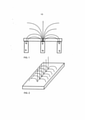
[0004] Um problema quando da produção do campo magnético éque, com um campo axialmente simétrico, que é diferente de zero no centro, as linhas de campo no centro sempre saem do alvo perpendicularmente à superfície. Isso está representado para um alvo redondo esquematicamente na figura 1 e para um alvo retangular esquematicamente na figura 2. Nas regiões, em que as linhas de campo são es- sencialmente perpendiculares à superfície do alvo, a velocidade de migração do ponto de combustão de catodo diminui acentuadamente. Esse efeito pode ser designado como colapso do ponto de combustão de catodo no centro. Ocorre um acentuado desbaste de material com acentuada formação de "droplet" com relação ao número e também ao tamanho nessa região. "Droplets" são conglomerados essencialmente fluidos, isto é, não vaporizados, centrifugados da superfície do alvo, que se depositam como macropartículas sobre o substrato a ser revestido. Com processos de revestimento reativos, isso conduz frequentemente a que os conglomerados não possam reagir completamente com o gás reativo.[0004] One problem when producing the magnetic field is that, with an axially symmetric field, which is non-zero at the center, the field lines at the center always exit the target perpendicular to the surface. This is represented schematically for a round target in Figure 1 and for a rectangular target schematically in Figure 2. In regions, where the field lines are essentially perpendicular to the surface of the target, the migration velocity of the cathode combustion point sharply decreases. This effect can be referred to as the collapse of the cathode burning point at the center. There is an accentuated thinning of material with accentuated "droplet" formation in relation to the number and also to the size in this region. "Droplets" are essentially fluid conglomerates, i.e. non-vaporized, centrifuged from the surface of the target, which are deposited as macroparticles on the substrate to be coated. With reactive coating processes, this often leads to the conglomerates not being able to fully react with the reactive gas.
[0005] Contra esse colapso do ponto de combustão de catodo nocentro do alvo são conhecidas essencialmente duas medidas.[0005] Against this collapse of the cathode burning point at the center of the target, essentially two measures are known.
[0006] De um lado, pode se tentar evitar o colapso por escolhahabilidosa do sistema magnético. Isso é obtido, por exemplo, por linhas de campo magnético divergentes. Todavia, é sabido que mediante focagem de campos magnéticos o material a ser vaporizado pode ser mais acentuadamente levado ao substrato a ser revestido e assim aumentada a eficiência do emprego do material. Pelo emprego de linhas de campo magnético divergentes é preciso renunciar a essa vantagem.[0006] On the one hand, one can try to avoid the collapse by skillful choice of the magnetic system. This is achieved, for example, by diverging magnetic field lines. However, it is known that by focusing magnetic fields the material to be vaporized can be brought more sharply to the substrate to be coated and thus the efficiency of the use of the material is increased. By employing diverging magnetic field lines, this advantage must be given up.
[0007] De outro lado, é sabido tomar medidas que limitam o pontode combustão de catodo, apesar de eliminarem linhas de campo magnético saindo perpendicularmente da região central do alvo, isto é, a regiões do alvo fora da região central. Conforme a WO 0016373, por conseguinte, o problema do colapso na região central do ponto de combustão de catodo é diminuído pelo fato de que na região central do alvo é previsto um anteparo, cujo material apresenta um rendimento de elétron secundários menor. Como material de anteparo é ali empregado por exemplo nitrito de boro. Com essa proposta se revela, contudo, o problema de que pelo revestimento da superfície do anteparo este se torna eletricamente condutor, o ponto de combustão de catodo pode migrar para a superfície do anteparo e, com isso, podem surgir indesejados componentes na camada a ser estabelecida.[0007] On the other hand, it is known to take measures that limit the cathode combustion point, despite eliminating magnetic field lines coming out perpendicularly from the central region of the target, that is, to regions of the target outside the central region. According to WO 0016373, therefore, the problem of collapse in the central region of the cathode combustion point is reduced by the fact that a shield is provided in the central region of the target, whose material has a lower yield of secondary electrons. As a shielding material, for example, boron nitrite is used. With this proposal, however, the problem is revealed that, by coating the surface of the shield, it becomes electrically conductive, the cathode combustion point can migrate to the surface of the shield and, with that, unwanted components may arise in the layer to be established.
[0008] A presente invenção tem por objetivo superar ao menosparcialmente as desvantagens do estado atual da técnica. Com as medidas tomadas deve ainda ser garantida a eficácia no ambiente de produção de empresas pré-tratamento. Requisitos correspondentes se aplicam a baixos custos, processabilidade e facilidade de manutenção.[0008] The present invention aims to at least partially overcome the disadvantages of the current state of the art. With the measures taken, effectiveness in the production environment of pre-treatment companies must still be guaranteed. Corresponding requirements apply to low cost, processability and ease of maintenance.
[0009] Os inventores reconheceram que um problema na WO0016373 reside em que, devido ao contato entre anteparo e material de vaporização, com crescente revestimento é formado um composto eletricamente condutor, que possibilita a descarga de centelha sobre a superfície do anteparo apesar de menor rendimento de elétrons secundários.[0009] The inventors recognized that a problem in WO0016373 resides in that, due to the contact between the shield and the vaporization material, with increasing coating an electrically conductive compound is formed, which allows the discharge of spark on the surface of the shield despite lower efficiency. of secondary electrons.
[00010] Segundo a invenção, portanto, o ponto de combustão de catodo é muito eficazmente removido da região central da superfície do alvo na medida em que nessa região o avanço de eletrodos é permanentemente impedido durante o processo de revestimento, isto é, a descarga de centelha apensar da inércia de corrente é excluída. Isso pode então ser obtido pelo fato de que a região central é permanentemente isolada e disposta em potencial eletricamente flutuante. Surpreendentemente, então, quando esse avanço de eletrodos na região central do alvo é permanentemente impedido, como material de anteparo até mesmo pode ser empregado o material idêntico à restante superfície do alvo. O emprego de materiais, que apresentar um menor rendimento de elétrons secundário, não é mais, portanto, condição bá-sica. Caso o ponto de combustão de catodo venha eventualmente a se deslocar por curto tempo para o anteparo, nesse caso isso não conduz a uma poluição das camadas.[00010] According to the invention, therefore, the cathode burning point is very effectively removed from the central region of the target surface as in this region the advancement of electrodes is permanently impeded during the coating process, i.e., the discharge of spark despite current inertia is excluded. This can then be achieved by the fact that the central region is permanently isolated and arranged in an electrically fluctuating potential. Surprisingly, then, when this advance of electrodes in the central region of the target is permanently impeded, as a shield material even material identical to the remaining surface of the target can be used. The use of materials that present a lower yield of secondary electrons is therefore no longer a basic condition. If the cathode combustion point eventually moves to the screen for a short time, then this does not lead to pollution of the layers.
[00011] A invenção será então representada detalhadamente a título de exemplo com base nos exemplos e figuras. Mostram:figura 3 - uma forma de execução segundo a invenção de um alvo com um disco em execução não magnética e esquematicamente o traçado das linhas de campo.figura 4 - uma forma de execução segundo a invenção de um alvo com um disco em execução magnética com material magnético macio e esquematicamente o traçado das linhas de campo.[00011] The invention will then be represented in detail by way of example based on the examples and figures. They show: figure 3 - a form of execution according to the invention of a target with a disk in non-magnetic execution and schematically the tracing of the field lines. figure 4 - a form of execution according to the invention of a target with a disk in magnetic execution with soft magnetic material and schematically tracing the field lines.
[00012] Segundo um primeiro exemplo de execução, o alvo 1, como mostra a figura 3, compreende um material de alvo 3, no exemplo titânio com um recesso na região central para alojamento de um disco 7 disposto eletricamente isolado, que é retido em um pino isolante 9 por meio de um anel de segurança 11. Como pino isolante 9 é apropriado, por exemplo, um material cerâmico eletricamente não condutor. As distâncias entre material de alvo 3 e o disco 7 importam em cerca de 1.5 mm e 3.5 mm. Com distância maior, há o perigo de que o ponto de combustão de catodo fique aquém do disco 7 situado em potencial flutuante. Com distância ainda menor do que 1.5 mm há o perigo de que pelo crescimento de material de revestimento ocorra um contato elétri-co entre material de alvo 3 e disco 7.[00012] According to a first embodiment example, the
[00013] Para a produção do alvo, de preferência inicialmente é aplicado um disco de material de alvo sobre um disco de suporte (não mostrado), que serve tanto para o resfriamento como também para o contato elétrico. Só em seguida, é completado o travamento mecânico do pino isolante 9, do disco 7 e do anel de segurança 11.[00013] For the production of the target, preferably initially a disc of target material is applied on a support disc (not shown), which serves both for cooling and also for electrical contact. Only then is the mechanical locking of the insulating pin 9, the
[00014] Em muitas aplicações, o alvo 1 fica disposto nas paredes laterais da câmara de revestimento. Isso significa para um alvo redondo que o eixo de simetria do alvo 1 se situa na horizontal. O disco 7 compreende no exemplo um furo com que é deslocada sobre o pino isolante 9. De preferência, o diâmetro do furo é selecionado ao menos alguns décimos de milímetro maior do que o diâmetro da parte de pino isolante 9, que é deslocada pelo furo. Devido à força gravitacional, portanto, o disco 7 assenta sobre uma linha na parte superior de invólucro do pino isolante 9. O anel de segurança 11, como mostrado na figura 3, é rebaixado em um recesso central do disco 7. Assim, a linha de assento se reduz ainda mais e, no mais desfavorável dos casos, o ponto gravitacional do disco se situa de tal forma que o disco 7 devido à tolerância é posicionado dobrado sobre o invólucro do pino isolante 9. Para impedir isso, o disco 7 compreende, segundo outra configuração inventiva dessa forma de execução, uma ou várias moldagens 13. Essas moldagens 13 fazem com que o ponto gravitacional do disco 7 sobre o eixo se desloque para longo do anel de segurança 11 e assim o disco 7 não é posicionado dobrado.[00014] In many applications, the
[00015] O disco 7 consiste, segundo a presente forma de execução, em material eletricamente condutor, por exemplo metálico. Segundo uma forma de execução particularmente vantajosa, o disco 7 flutuante pode também ser executado como material magnético macio, com o que pode ser obtido que as linhas de campo na aresta exterior do disco saiam perpendicularmente e, com isso, se situem essencialmente paralelas à superfície do alvo, como representado na figura 4 por meio de linhas tracejadas no lado direito. Assim é garantida uma rápida velocidade de migração do ponto de combustão de catodo por toda a região de alvo restante.[00015] The
[00016] Na presente descrição, foi apresentado um alvo para uma fonte ARC com um primeiro corpo 3 de um material a ser vaporizado, que compreende essencialmente em um plano uma superfície prevista para vaporização, sendo que a superfície nesse plano envolve uma região central, caracterizado pelo fato de que na região central está previsto um segundo corpo 7, executado de preferência em forma de placa, eletricamente isolado do primeiro corpo 3 de tal maneira, que pelo segundo corpo essencialmente não podem ser disponibilizados elétrons para manutenção de uma centelha.[00016] In the present description, a target was presented for an ARC source with a
[00017] De preferência, o primeiro corpo 3 compreende na região central 5 um recesso, em que está rebaixado o segundo corpo 7 e fixado por meio de um pino isolante 9, sendo que a distância entre o primeiro corpo 3 e o segundo corpo 9 assume um ou vários valores entre inclusive 1.5 mm e 3.5 mm, sendo que em uma forma de execução particularmente preferida o corpo 7 apresenta ao menos na superfície que se projeta do recesso 5 material que corresponde ao material do corpo 3.[00017] Preferably, the
[00018] O segundo corpo 7 pode compreender uma ou várias moldagens 13 de tal maneira que o ponto gravitacional do segundo corpo 7 situado no eixo vem a se situar na altura do invólucro do furo.[00018] The
[00019] Em outra forma de execução particularmente preferida, o segundo corpo 7 é executado de material magnético macio.[00019] In another particularly preferred embodiment, the
Claims (5)
Applications Claiming Priority (5)
| Application Number | Priority Date | Filing Date | Title |
|---|---|---|---|
| US32492910P | 2010-04-16 | 2010-04-16 | |
| US61/324,929 | 2010-04-16 | ||
| DE102010020737.3 | 2010-05-17 | ||
| DE102010020737A DE102010020737A1 (en) | 2010-05-17 | 2010-05-17 | Target for spark evaporation with spatial limitation of the propagation of the spark |
| PCT/EP2011/000057 WO2011128004A1 (en) | 2010-04-16 | 2011-01-10 | Target for spark vaporization with physical limiting of the propogation of the spark |
Publications (2)
| Publication Number | Publication Date |
|---|---|
| BR112012026552A2 BR112012026552A2 (en) | 2016-07-12 |
| BR112012026552B1 true BR112012026552B1 (en) | 2022-01-11 |
Family
ID=43735926
Family Applications (1)
| Application Number | Title | Priority Date | Filing Date |
|---|---|---|---|
| BR112012026552-0A BR112012026552B1 (en) | 2010-04-16 | 2011-01-10 | TARGET FOR AN ARC SOURCE WITH A FIRST BODY OF A MATERIAL TO BE VAPORIZED |
Country Status (12)
| Country | Link |
|---|---|
| US (1) | US9657389B2 (en) |
| EP (1) | EP2559050B1 (en) |
| JP (1) | JP5757991B2 (en) |
| KR (1) | KR101784540B1 (en) |
| CN (1) | CN102822938B (en) |
| BR (1) | BR112012026552B1 (en) |
| CA (1) | CA2796394C (en) |
| DE (1) | DE102010020737A1 (en) |
| MX (1) | MX338452B (en) |
| RU (1) | RU2562909C2 (en) |
| TW (1) | TWI544101B (en) |
| WO (1) | WO2011128004A1 (en) |
Family Cites Families (13)
| Publication number | Priority date | Publication date | Assignee | Title |
|---|---|---|---|---|
| JPS62218562A (en) * | 1986-03-19 | 1987-09-25 | Fujitsu Ltd | Sputtering device |
| US5298136A (en) * | 1987-08-18 | 1994-03-29 | Regents Of The University Of Minnesota | Steered arc coating with thick targets |
| DE4401986A1 (en) | 1994-01-25 | 1995-07-27 | Dresden Vakuumtech Gmbh | Method for operating a vacuum arc evaporator and power supply device therefor |
| CH689558A5 (en) * | 1995-07-11 | 1999-06-15 | Erich Bergmann | Vaporization and evaporator unit. |
| US6344114B1 (en) * | 1996-12-21 | 2002-02-05 | Singulus Technologies Ag | Magnetron sputtering cathode with magnet disposed between two yoke plates |
| WO2000016373A1 (en) | 1998-09-14 | 2000-03-23 | Unaxis Trading Ag | Target array for an arc vapor deposition chamber |
| CA2268659C (en) * | 1999-04-12 | 2008-12-30 | Vladimir I. Gorokhovsky | Rectangular cathodic arc source and method of steering an arc spot |
| US6783638B2 (en) * | 2001-09-07 | 2004-08-31 | Sputtered Films, Inc. | Flat magnetron |
| ATE367232T1 (en) * | 2002-03-23 | 2007-08-15 | Metal Nanopowders Ltd | METHOD FOR PRODUCING POWDER |
| JP2005126737A (en) * | 2003-10-21 | 2005-05-19 | Riken Corp | Arc type evaporation source |
| US20060049041A1 (en) * | 2004-08-20 | 2006-03-09 | Jds Uniphase Corporation | Anode for sputter coating |
| BRPI0711644B1 (en) * | 2006-05-16 | 2019-03-19 | Oerlikon Trading Ag, Trübbach | VOLTAGE ARC SOURCE WITH A TARGET AND PROCESS FOR PRODUCTION OF VOLTAGE ARC COVERED PARTS |
| US20100018857A1 (en) * | 2008-07-23 | 2010-01-28 | Seagate Technology Llc | Sputter cathode apparatus allowing thick magnetic targets |
-
2010
- 2010-05-17 DE DE102010020737A patent/DE102010020737A1/en not_active Withdrawn
-
2011
- 2011-01-10 CN CN201180019323.XA patent/CN102822938B/en active Active
- 2011-01-10 WO PCT/EP2011/000057 patent/WO2011128004A1/en not_active Ceased
- 2011-01-10 JP JP2013504138A patent/JP5757991B2/en active Active
- 2011-01-10 BR BR112012026552-0A patent/BR112012026552B1/en active IP Right Grant
- 2011-01-10 MX MX2012012055A patent/MX338452B/en active IP Right Grant
- 2011-01-10 RU RU2012148715/07A patent/RU2562909C2/en active
- 2011-01-10 CA CA2796394A patent/CA2796394C/en active Active
- 2011-01-10 US US13/641,499 patent/US9657389B2/en active Active
- 2011-01-10 KR KR1020127026973A patent/KR101784540B1/en active Active
- 2011-01-10 EP EP11701194.0A patent/EP2559050B1/en active Active
- 2011-04-14 TW TW100112896A patent/TWI544101B/en active
Also Published As
| Publication number | Publication date |
|---|---|
| US9657389B2 (en) | 2017-05-23 |
| TWI544101B (en) | 2016-08-01 |
| TW201207141A (en) | 2012-02-16 |
| CA2796394C (en) | 2019-07-09 |
| DE102010020737A1 (en) | 2011-11-17 |
| US20130126348A1 (en) | 2013-05-23 |
| CN102822938B (en) | 2016-05-04 |
| EP2559050A1 (en) | 2013-02-20 |
| KR20130064045A (en) | 2013-06-17 |
| RU2562909C2 (en) | 2015-09-10 |
| WO2011128004A1 (en) | 2011-10-20 |
| JP5757991B2 (en) | 2015-08-05 |
| KR101784540B1 (en) | 2017-10-11 |
| RU2012148715A (en) | 2014-05-27 |
| MX2012012055A (en) | 2012-12-17 |
| CN102822938A (en) | 2012-12-12 |
| MX338452B (en) | 2016-04-18 |
| JP2013525600A (en) | 2013-06-20 |
| EP2559050B1 (en) | 2017-06-07 |
| CA2796394A1 (en) | 2011-10-20 |
| BR112012026552A2 (en) | 2016-07-12 |
Similar Documents
| Publication | Publication Date | Title |
|---|---|---|
| JP6006286B2 (en) | Neutral beam source including belt-type magnet | |
| JP6646767B2 (en) | Indirectly heated cathode ion source and Bernas ion source | |
| CN114375484B (en) | Ion source, thermally isolated repeller and electrode used in the ion source | |
| CN114641843B (en) | Indirectly heated cathode ion source and target support | |
| BR112012033065B1 (en) | Arc evaporation device and vacuum treatment device | |
| BR112012033035B1 (en) | arc evaporation source having high speed film forming method, coating film making method and film forming apparatus using arc evaporation source | |
| BR112012026552B1 (en) | TARGET FOR AN ARC SOURCE WITH A FIRST BODY OF A MATERIAL TO BE VAPORIZED | |
| US20160348232A1 (en) | Anode layer ion source and ion beam sputter deposition module | |
| KR101353773B1 (en) | Ion beam source | |
| CN204982041U (en) | Magnetron sputtering target | |
| JP2016529735A (en) | Barrier layer for electrostatic chuck | |
| UA113607C2 (en) | ELECTRONIC BEAM LAMP WITH LINEAR THERMOCATODE | |
| BR112016030966B1 (en) | ARC EVAPORATION SOURCE | |
| KR101395485B1 (en) | Plasma Source With Belt Type Magnet Assemblies | |
| KR101465982B1 (en) | Metallic sector for glass melter and coating method thereof | |
| CN211128368U (en) | Device for mitigating ignition of ion source gas supply pipeline and ion source hydrogen pipeline | |
| KR101683726B1 (en) | apparatus for processing substrates | |
| JP4722801B2 (en) | Deposition equipment | |
| Wang et al. | Negative Charge Management to Make Fragile Bonds No Longer Fragile towards Electrons for Robust Organic Optoelectronic Materials | |
| BR112014031757B1 (en) | arc evaporation source | |
| KR20160104639A (en) | Electrode assembly for deposition apparatus and method for assembling said electrode assembly | |
| SG193732A1 (en) | Cathode module | |
| JP2008001925A (en) | Film deposition apparatus | |
| JP2008266732A (en) | Vacuum deposition system | |
| CN108269724A (en) | Electron gun and its method of work |
Legal Events
| Date | Code | Title | Description |
|---|---|---|---|
| B25G | Requested change of headquarter approved |
Owner name: OERLIKON TRADING AG, TRUEBBACH (CH) |
|
| B06F | Objections, documents and/or translations needed after an examination request according [chapter 6.6 patent gazette] | ||
| B06U | Preliminary requirement: requests with searches performed by other patent offices: procedure suspended [chapter 6.21 patent gazette] | ||
| B07A | Application suspended after technical examination (opinion) [chapter 7.1 patent gazette] | ||
| B09A | Decision: intention to grant [chapter 9.1 patent gazette] | ||
| B16A | Patent or certificate of addition of invention granted [chapter 16.1 patent gazette] |
Free format text: PRAZO DE VALIDADE: 20 (VINTE) ANOS CONTADOS A PARTIR DE 10/01/2011, OBSERVADAS AS CONDICOES LEGAIS. PATENTE CONCEDIDA CONFORME ADI 5.529/DF, QUE DETERMINA A ALTERACAO DO PRAZO DE CONCESSAO. |
|
| B25D | Requested change of name of applicant approved |
Owner name: OERLIKON SURFACE SOLUTIONS AG, PFAEFFIKON (CH) |
|
| B25G | Requested change of headquarter approved |
Owner name: OERLIKON SURFACE SOLUTIONS AG, PFAEFFIKON (CH) |