BR112012025792B1 - INSTALLATION, AND, GAS-IN-LIQUID CONVERSION PROCESS FOR TREATMENT OF NATURAL GAS - Google Patents
INSTALLATION, AND, GAS-IN-LIQUID CONVERSION PROCESS FOR TREATMENT OF NATURAL GAS Download PDFInfo
- Publication number
- BR112012025792B1 BR112012025792B1 BR112012025792-7A BR112012025792A BR112012025792B1 BR 112012025792 B1 BR112012025792 B1 BR 112012025792B1 BR 112012025792 A BR112012025792 A BR 112012025792A BR 112012025792 B1 BR112012025792 B1 BR 112012025792B1
- Authority
- BR
- Brazil
- Prior art keywords
- gas
- natural gas
- flow limiter
- installation
- combustion
- Prior art date
Links
Images
Classifications
-
- C—CHEMISTRY; METALLURGY
- C01—INORGANIC CHEMISTRY
- C01B—NON-METALLIC ELEMENTS; COMPOUNDS THEREOF; METALLOIDS OR COMPOUNDS THEREOF NOT COVERED BY SUBCLASS C01C
- C01B3/00—Hydrogen; Gaseous mixtures containing hydrogen; Separation of hydrogen from mixtures containing it; Purification of hydrogen
- C01B3/02—Production of hydrogen or of gaseous mixtures containing a substantial proportion of hydrogen
- C01B3/32—Production of hydrogen or of gaseous mixtures containing a substantial proportion of hydrogen by reaction of gaseous or liquid organic compounds with gasifying agents, e.g. water, carbon dioxide, air
- C01B3/34—Production of hydrogen or of gaseous mixtures containing a substantial proportion of hydrogen by reaction of gaseous or liquid organic compounds with gasifying agents, e.g. water, carbon dioxide, air by reaction of hydrocarbons with gasifying agents
-
- F—MECHANICAL ENGINEERING; LIGHTING; HEATING; WEAPONS; BLASTING
- F25—REFRIGERATION OR COOLING; COMBINED HEATING AND REFRIGERATION SYSTEMS; HEAT PUMP SYSTEMS; MANUFACTURE OR STORAGE OF ICE; LIQUEFACTION SOLIDIFICATION OF GASES
- F25J—LIQUEFACTION, SOLIDIFICATION OR SEPARATION OF GASES OR GASEOUS OR LIQUEFIED GASEOUS MIXTURES BY PRESSURE AND COLD TREATMENT OR BY BRINGING THEM INTO THE SUPERCRITICAL STATE
- F25J3/00—Processes or apparatus for separating the constituents of gaseous or liquefied gaseous mixtures involving the use of liquefaction or solidification
-
- C—CHEMISTRY; METALLURGY
- C01—INORGANIC CHEMISTRY
- C01B—NON-METALLIC ELEMENTS; COMPOUNDS THEREOF; METALLOIDS OR COMPOUNDS THEREOF NOT COVERED BY SUBCLASS C01C
- C01B3/00—Hydrogen; Gaseous mixtures containing hydrogen; Separation of hydrogen from mixtures containing it; Purification of hydrogen
- C01B3/02—Production of hydrogen or of gaseous mixtures containing a substantial proportion of hydrogen
- C01B3/32—Production of hydrogen or of gaseous mixtures containing a substantial proportion of hydrogen by reaction of gaseous or liquid organic compounds with gasifying agents, e.g. water, carbon dioxide, air
-
- C—CHEMISTRY; METALLURGY
- C07—ORGANIC CHEMISTRY
- C07C—ACYCLIC OR CARBOCYCLIC COMPOUNDS
- C07C1/00—Preparation of hydrocarbons from one or more compounds, none of them being a hydrocarbon
- C07C1/02—Preparation of hydrocarbons from one or more compounds, none of them being a hydrocarbon from oxides of a carbon
- C07C1/04—Preparation of hydrocarbons from one or more compounds, none of them being a hydrocarbon from oxides of a carbon from carbon monoxide with hydrogen
-
- C—CHEMISTRY; METALLURGY
- C10—PETROLEUM, GAS OR COKE INDUSTRIES; TECHNICAL GASES CONTAINING CARBON MONOXIDE; FUELS; LUBRICANTS; PEAT
- C10G—CRACKING HYDROCARBON OILS; PRODUCTION OF LIQUID HYDROCARBON MIXTURES, e.g. BY DESTRUCTIVE HYDROGENATION, OLIGOMERISATION, POLYMERISATION; RECOVERY OF HYDROCARBON OILS FROM OIL-SHALE, OIL-SAND, OR GASES; REFINING MIXTURES MAINLY CONSISTING OF HYDROCARBONS; REFORMING OF NAPHTHA; MINERAL WAXES
- C10G2/00—Production of liquid hydrocarbon mixtures of undefined composition from oxides of carbon
- C10G2/30—Production of liquid hydrocarbon mixtures of undefined composition from oxides of carbon from carbon monoxide with hydrogen
- C10G2/32—Production of liquid hydrocarbon mixtures of undefined composition from oxides of carbon from carbon monoxide with hydrogen with the use of catalysts
-
- C—CHEMISTRY; METALLURGY
- C10—PETROLEUM, GAS OR COKE INDUSTRIES; TECHNICAL GASES CONTAINING CARBON MONOXIDE; FUELS; LUBRICANTS; PEAT
- C10L—FUELS NOT OTHERWISE PROVIDED FOR; NATURAL GAS; SYNTHETIC NATURAL GAS OBTAINED BY PROCESSES NOT COVERED BY SUBCLASSES C10G, C10K; LIQUEFIED PETROLEUM GAS; ADDING MATERIALS TO FUELS OR FIRES TO REDUCE SMOKE OR UNDESIRABLE DEPOSITS OR TO FACILITATE SOOT REMOVAL; FIRELIGHTERS
- C10L3/00—Gaseous fuels; Natural gas; Synthetic natural gas obtained by processes not covered by subclass C10G, C10K; Liquefied petroleum gas
- C10L3/06—Natural gas; Synthetic natural gas obtained by processes not covered by C10G, C10K3/02 or C10K3/04
- C10L3/10—Working-up natural gas or synthetic natural gas
-
- C—CHEMISTRY; METALLURGY
- C01—INORGANIC CHEMISTRY
- C01B—NON-METALLIC ELEMENTS; COMPOUNDS THEREOF; METALLOIDS OR COMPOUNDS THEREOF NOT COVERED BY SUBCLASS C01C
- C01B2203/00—Integrated processes for the production of hydrogen or synthesis gas
- C01B2203/02—Processes for making hydrogen or synthesis gas
- C01B2203/0205—Processes for making hydrogen or synthesis gas containing a reforming step
- C01B2203/0227—Processes for making hydrogen or synthesis gas containing a reforming step containing a catalytic reforming step
- C01B2203/0233—Processes for making hydrogen or synthesis gas containing a reforming step containing a catalytic reforming step the reforming step being a steam reforming step
-
- C—CHEMISTRY; METALLURGY
- C01—INORGANIC CHEMISTRY
- C01B—NON-METALLIC ELEMENTS; COMPOUNDS THEREOF; METALLOIDS OR COMPOUNDS THEREOF NOT COVERED BY SUBCLASS C01C
- C01B2203/00—Integrated processes for the production of hydrogen or synthesis gas
- C01B2203/02—Processes for making hydrogen or synthesis gas
- C01B2203/0205—Processes for making hydrogen or synthesis gas containing a reforming step
- C01B2203/0227—Processes for making hydrogen or synthesis gas containing a reforming step containing a catalytic reforming step
- C01B2203/0244—Processes for making hydrogen or synthesis gas containing a reforming step containing a catalytic reforming step the reforming step being an autothermal reforming step, e.g. secondary reforming processes
-
- C—CHEMISTRY; METALLURGY
- C01—INORGANIC CHEMISTRY
- C01B—NON-METALLIC ELEMENTS; COMPOUNDS THEREOF; METALLOIDS OR COMPOUNDS THEREOF NOT COVERED BY SUBCLASS C01C
- C01B2203/00—Integrated processes for the production of hydrogen or synthesis gas
- C01B2203/02—Processes for making hydrogen or synthesis gas
- C01B2203/025—Processes for making hydrogen or synthesis gas containing a partial oxidation step
-
- C—CHEMISTRY; METALLURGY
- C01—INORGANIC CHEMISTRY
- C01B—NON-METALLIC ELEMENTS; COMPOUNDS THEREOF; METALLOIDS OR COMPOUNDS THEREOF NOT COVERED BY SUBCLASS C01C
- C01B2203/00—Integrated processes for the production of hydrogen or synthesis gas
- C01B2203/04—Integrated processes for the production of hydrogen or synthesis gas containing a purification step for the hydrogen or the synthesis gas
- C01B2203/0405—Purification by membrane separation
-
- C—CHEMISTRY; METALLURGY
- C01—INORGANIC CHEMISTRY
- C01B—NON-METALLIC ELEMENTS; COMPOUNDS THEREOF; METALLOIDS OR COMPOUNDS THEREOF NOT COVERED BY SUBCLASS C01C
- C01B2203/00—Integrated processes for the production of hydrogen or synthesis gas
- C01B2203/04—Integrated processes for the production of hydrogen or synthesis gas containing a purification step for the hydrogen or the synthesis gas
- C01B2203/042—Purification by adsorption on solids
- C01B2203/043—Regenerative adsorption process in two or more beds, one for adsorption, the other for regeneration
-
- C—CHEMISTRY; METALLURGY
- C01—INORGANIC CHEMISTRY
- C01B—NON-METALLIC ELEMENTS; COMPOUNDS THEREOF; METALLOIDS OR COMPOUNDS THEREOF NOT COVERED BY SUBCLASS C01C
- C01B2203/00—Integrated processes for the production of hydrogen or synthesis gas
- C01B2203/06—Integration with other chemical processes
- C01B2203/062—Hydrocarbon production, e.g. Fischer-Tropsch process
-
- C—CHEMISTRY; METALLURGY
- C01—INORGANIC CHEMISTRY
- C01B—NON-METALLIC ELEMENTS; COMPOUNDS THEREOF; METALLOIDS OR COMPOUNDS THEREOF NOT COVERED BY SUBCLASS C01C
- C01B2203/00—Integrated processes for the production of hydrogen or synthesis gas
- C01B2203/08—Methods of heating or cooling
- C01B2203/0805—Methods of heating the process for making hydrogen or synthesis gas
- C01B2203/0811—Methods of heating the process for making hydrogen or synthesis gas by combustion of fuel
- C01B2203/0822—Methods of heating the process for making hydrogen or synthesis gas by combustion of fuel the fuel containing hydrogen
-
- C—CHEMISTRY; METALLURGY
- C01—INORGANIC CHEMISTRY
- C01B—NON-METALLIC ELEMENTS; COMPOUNDS THEREOF; METALLOIDS OR COMPOUNDS THEREOF NOT COVERED BY SUBCLASS C01C
- C01B2203/00—Integrated processes for the production of hydrogen or synthesis gas
- C01B2203/08—Methods of heating or cooling
- C01B2203/0805—Methods of heating the process for making hydrogen or synthesis gas
- C01B2203/0811—Methods of heating the process for making hydrogen or synthesis gas by combustion of fuel
- C01B2203/0827—Methods of heating the process for making hydrogen or synthesis gas by combustion of fuel at least part of the fuel being a recycle stream
-
- C—CHEMISTRY; METALLURGY
- C01—INORGANIC CHEMISTRY
- C01B—NON-METALLIC ELEMENTS; COMPOUNDS THEREOF; METALLOIDS OR COMPOUNDS THEREOF NOT COVERED BY SUBCLASS C01C
- C01B2203/00—Integrated processes for the production of hydrogen or synthesis gas
- C01B2203/08—Methods of heating or cooling
- C01B2203/0872—Methods of cooling
- C01B2203/0888—Methods of cooling by evaporation of a fluid
- C01B2203/0894—Generation of steam
-
- C—CHEMISTRY; METALLURGY
- C01—INORGANIC CHEMISTRY
- C01B—NON-METALLIC ELEMENTS; COMPOUNDS THEREOF; METALLOIDS OR COMPOUNDS THEREOF NOT COVERED BY SUBCLASS C01C
- C01B2203/00—Integrated processes for the production of hydrogen or synthesis gas
- C01B2203/10—Catalysts for performing the hydrogen forming reactions
- C01B2203/1041—Composition of the catalyst
- C01B2203/1047—Group VIII metal catalysts
- C01B2203/1064—Platinum group metal catalysts
-
- C—CHEMISTRY; METALLURGY
- C01—INORGANIC CHEMISTRY
- C01B—NON-METALLIC ELEMENTS; COMPOUNDS THEREOF; METALLOIDS OR COMPOUNDS THEREOF NOT COVERED BY SUBCLASS C01C
- C01B2203/00—Integrated processes for the production of hydrogen or synthesis gas
- C01B2203/12—Feeding the process for making hydrogen or synthesis gas
- C01B2203/1205—Composition of the feed
- C01B2203/1211—Organic compounds or organic mixtures used in the process for making hydrogen or synthesis gas
- C01B2203/1235—Hydrocarbons
- C01B2203/1241—Natural gas or methane
-
- C—CHEMISTRY; METALLURGY
- C01—INORGANIC CHEMISTRY
- C01B—NON-METALLIC ELEMENTS; COMPOUNDS THEREOF; METALLOIDS OR COMPOUNDS THEREOF NOT COVERED BY SUBCLASS C01C
- C01B2203/00—Integrated processes for the production of hydrogen or synthesis gas
- C01B2203/14—Details of the flowsheet
- C01B2203/148—Details of the flowsheet involving a recycle stream to the feed of the process for making hydrogen or synthesis gas
-
- C—CHEMISTRY; METALLURGY
- C10—PETROLEUM, GAS OR COKE INDUSTRIES; TECHNICAL GASES CONTAINING CARBON MONOXIDE; FUELS; LUBRICANTS; PEAT
- C10G—CRACKING HYDROCARBON OILS; PRODUCTION OF LIQUID HYDROCARBON MIXTURES, e.g. BY DESTRUCTIVE HYDROGENATION, OLIGOMERISATION, POLYMERISATION; RECOVERY OF HYDROCARBON OILS FROM OIL-SHALE, OIL-SAND, OR GASES; REFINING MIXTURES MAINLY CONSISTING OF HYDROCARBONS; REFORMING OF NAPHTHA; MINERAL WAXES
- C10G2300/00—Aspects relating to hydrocarbon processing covered by groups C10G1/00 - C10G99/00
- C10G2300/10—Feedstock materials
- C10G2300/1025—Natural gas
-
- Y—GENERAL TAGGING OF NEW TECHNOLOGICAL DEVELOPMENTS; GENERAL TAGGING OF CROSS-SECTIONAL TECHNOLOGIES SPANNING OVER SEVERAL SECTIONS OF THE IPC; TECHNICAL SUBJECTS COVERED BY FORMER USPC CROSS-REFERENCE ART COLLECTIONS [XRACs] AND DIGESTS
- Y02—TECHNOLOGIES OR APPLICATIONS FOR MITIGATION OR ADAPTATION AGAINST CLIMATE CHANGE
- Y02P—CLIMATE CHANGE MITIGATION TECHNOLOGIES IN THE PRODUCTION OR PROCESSING OF GOODS
- Y02P20/00—Technologies relating to chemical industry
- Y02P20/10—Process efficiency
Abstract
INSTALAÇÃO, E, PROCESSO DE CONVERSÃO DE GÁS-EM-LÍQUIDO PARA TRATAMENTO DE GÁS NATURAL Um processo e uma instalação de conversão de gás-em-líquido (10) para tratamento de gás natural (5), em que o gás natural é submetido à expansão através de um limitador de fluxo (16), de modo a sofrer resfriamento através do efeito Joule Thomson, permitem que líquidos (21, 22) sejam separados da corrente de gás. O gás pode ser resfriado antes do mesmo alcançar o limitador de fluxo (16) por troca térmica com o fluido que passou através do limitador de fluxo (16). Isto diminui a proporção de hidrocarbonetos de cadeia mais longa no gás natural, o que pode simplificar o processamento subsequente e pode permitir que o tamanho da instalação seja diminuído.INSTALLATION, AND, GAS-IN-LIQUID CONVERSION PROCESS FOR TREATING NATURAL GAS A gas-to-liquid conversion process and installation (10) for natural gas treatment (5), in which natural gas is subjected expansion through a flow limiter (16), in order to be cooled by the Joule Thomson effect, allow liquids (21, 22) to be separated from the gas stream. The gas can be cooled before it reaches the flow limiter (16) by thermal exchange with the fluid that has passed through the flow limiter (16). This decreases the proportion of long-chain hydrocarbons in natural gas, which can simplify subsequent processing and can allow the size of the facility to be reduced.
Description
A presente invenção refere-se a uma instalação e a um processo para tratamento de gás natural para produzir um produto líquido.The present invention relates to an installation and a process for treating natural gas to produce a liquid product.
É bem conhecido que a maioria dos poços de petróleo também produz gás natural. Em muitos poços de petróleo, gás natural é produzido em quantidades relativamente pequenas junto com o petróleo. Quando as quantidades deste gás associado são sufícientemente elevadas ou o poço está próximo de infraestrutura de transporte de gás pré-existente, o gás pode ser 10 transportado para uma instalação de processamento afastada do local. Quando a produção de petróleo ocorre em lugares mais remotos, é difícil introduzir o gás associado à infraestrutura existente de transporte de gás. Na ausência de tal infraestrutura, o gás associado tem sido tipicamente eliminado por queima em fiares ou re-injeção. No entanto, a queima em fiares não é mais uma abordagem 15 aceitável ambientalmente, enquanto que a re-injeção pode ter um impacto negativo sobre a qualidade da produção de petróleo a partir do campo.It is well known that most oil wells also produce natural gas. In many oil wells, natural gas is produced in relatively small quantities along with oil. When the quantities of this associated gas are sufficiently high or the well is close to a pre-existing gas transport infrastructure, the gas can be transported to a processing facility away from the site. When oil production takes place in more remote places, it is difficult to introduce the gas associated with the existing gas transport infrastructure. In the absence of such an infrastructure, the associated gas has typically been eliminated by flaring or re-injection. However, flaring is no longer an environmentally acceptable approach 15, while re-injection can have a negative impact on the quality of oil production from the field.
A tecnologia de conversão de gás-em-líquido pode ser usada para converter o gás natural em hidrocarbonetos líquidos e pode seguir uma abordagem em dois estágios para a produção de líquido a partir de 20 hidrocarbonetos compreendendo a geração de gás de síntese, seguida por síntese de Fischer-Tropsch. Em geral, gás de síntese (uma mistura de hidrogênio e monóxido de carbono) pode ser gerado por uma ou mais dentre . oxidação parcial, reforma autotérmica, ou reforma a vapor de metano. Onde a reforma a vapor de metano é usada, a reação é endotérmica e assim necessita de ■ 25 calor. O gás de síntese é então submetido à síntese de Fischer-Tropsch. Para realizar a síntese de Fischer-Tropsch a razão ótima de hidrogênio para monóxido de carbono é cerca de 2:1, e reforma a vapor tem um benefício de prover hidrogênio em maior quantidade do que a suficiente para esta finalidade.The gas-to-liquid conversion technology can be used to convert natural gas to liquid hydrocarbons and can follow a two-stage approach to the production of liquid from 20 hydrocarbons comprising the generation of synthesis gas, followed by synthesis Fischer-Tropsch. In general, synthesis gas (a mixture of hydrogen and carbon monoxide) can be generated by one or more of them. partial oxidation, autothermal reform, or steam reforming of methane. Where methane steam reforming is used, the reaction is endothermic and therefore requires ■ 25 heat. The synthesis gas is then subjected to Fischer-Tropsch synthesis. To perform the Fischer-Tropsch synthesis the optimal ratio of hydrogen to carbon monoxide is about 2: 1, and steam reforming has a benefit of providing more than enough hydrogen for this purpose.
Este processo é descrito, por exemplo, em WO 01/51194 (AEA Technology) e WO 03/006149 (Accentus plc). O gás natural é primariamente metano, mas também contém pequenas proporções de hidrocarbonetos de cadeia mais longa. Em cada caso, o gás natural é primeiro submetido a uma 5 etapa de pré-reforma, em que os hidrocarbonetos de cadeia mais longa são convertidos em metano por reação com vapor, por exemplo, sobre um catalisador de níquel a 400°C. Com relação ao processo de Fischer-Tropsch, como descrito em WO 2004/050799 (GTL Microsystems AG), um catalisador apropriado usa partículas pequenas de cobalto em um suporte de cerâmica, mas 10 este catalisador pode sofrer uma reação deletéria na presença de vapor d’água. Para assegurar que isto não ocorra, o reator é operado de modo a assegurar que a conversão de Fischer-Tropsch não seja maior do que 70%, e, então, os gases resultantes são submetidos a um segundo estágio de Fischer- Tropsch. Embora isto proporcione um modo satisfatório de converter gás 15 natural em um produto de hidrocarboneto de cadeia mais longa, seria desejável prover uma instalação e um processo alternativos.This process is described, for example, in WO 01/51194 (AEA Technology) and WO 03/006149 (Accentus plc). Natural gas is primarily methane, but it also contains small proportions of longer chain hydrocarbons. In each case, natural gas is first subjected to a pre-reform step, in which the longer chain hydrocarbons are converted to methane by reaction with steam, for example, on a nickel catalyst at 400 ° C. With respect to the Fischer-Tropsch process, as described in WO 2004/050799 (GTL Microsystems AG), an appropriate catalyst uses small particles of cobalt in a ceramic support, but 10 this catalyst can undergo a deleterious reaction in the presence of d 'Water. To ensure that this does not occur, the reactor is operated in order to ensure that the Fischer-Tropsch conversion is not greater than 70%, and then the resulting gases are subjected to a second Fischer-Tropsch stage. While this provides a satisfactory way of converting natural gas into a longer chain hydrocarbon product, it would be desirable to provide an alternative installation and process.
De acordo com a presente invenção, provê-se uma instalação de conversão de gás-em-líquido para tratamento de gás natural, em que o gás natural é submetido à expansão através de um limitador de fluxo de modo a 20 sofrer resfriamento através do efeito Joule Thomson, com separação dos líquidos resultantes.In accordance with the present invention, a gas-to-liquid conversion facility is provided for the treatment of natural gas, in which the natural gas is subjected to expansion through a flow limiter so that it undergoes cooling through the effect Joule Thomson, with separation of the resulting liquids.
A presente invenção também provê um processo para tratamento de gás natural desta forma. O processo da presente invenção refere-se a um processo químico para a conversão de gás natural (primariamente metano) em 25 hidrocarbonetos de cadeia mais longa.The present invention also provides a process for treating natural gas in this way. The process of the present invention relates to a chemical process for converting natural gas (primarily methane) into 25 longer chain hydrocarbons.
Idealmente, a expansão ocorre sem transferência signifícante de calor do ambiente, o gás natural expandindo-se para um estado de pressão menor. O limitador de fluxo pode ser uma válvula de regulação, ou, altemativamente, pode ser um bocal de entrada de um separador de tubo de vórtice, ou um turboexpansor, ou um dispositivo separador Twister (TM). Um tubo de vórtice, ou tubo Ranque-Hilsch, divide o gás em uma corrente de gás quente e uma corrente de gás frio. A corrente de gás quente pode ser usada em 5 outros locais dentro da instalação. No entanto, como resultado da divisão em duas correntes, apenas uma parte dos gases são resfriados. A expansão pode resfriar o gás natural abaixo de 0°C, mais particularmente abaixo de -10°C, por exemplo, abaixo de -15°C, com a consequência de que hidrocarbonetos de cadeia mais longa condensam a partir do estado de vapor para o estado líquido, 10 e podem ser separados do gás natural restante. O grau de resfriamento é selecionado para assegurar que a corrente de saída está a uma pressão suficiente para conduzir o gás através do processo. Enquanto que a temperatura pode ser ainda diminuída a fim de aumentar a recuperação de hidrocarbonetos superiores, isto deixa de ser vantajoso quando o custo dos requisitos de 15 compressão aumentada para re-pressurização do gás exceder o valor dos hidrocarbonetos de cadeia mais longa adicionais recuperados. Preferivelmente, a corrente de gás natural é alimentada para dentro do limitador de fluxo através de um trocador de calor em que ela é resfriada por contato com pelo menos um fluido que foi resfriado por passagem através do limitador de fluxo, de modo 20 que o gás natural está abaixo da temperatura ambiente, quando ele atinge o limitador de fluxo.Ideally, expansion occurs without significant heat transfer from the environment, natural gas expanding to a lower pressure state. The flow limiter can be a regulating valve, or alternatively, it can be an inlet nozzle of a vortex tube separator, or a turboexpander, or a Twister (TM) separator device. A vortex tube, or Ranque-Hilsch tube, divides the gas into a stream of hot gas and a stream of cold gas. The hot gas stream can be used at 5 other locations within the facility. However, as a result of dividing into two streams, only a part of the gases are cooled. The expansion can cool natural gas below 0 ° C, more particularly below -10 ° C, for example, below -15 ° C, with the consequence that longer-chain hydrocarbons condense from the vapor state to the liquid state, 10 and can be separated from the remaining natural gas. The degree of cooling is selected to ensure that the outlet current is at a pressure sufficient to conduct the gas through the process. While the temperature can be further lowered in order to increase the recovery of higher hydrocarbons, this is no longer advantageous when the cost of the increased compression requirements for re-pressurizing the gas exceeds the value of the additional long-chain hydrocarbons recovered. Preferably, the natural gas stream is fed into the flow limiter through a heat exchanger in which it is cooled by contact with at least one fluid that has been cooled by passing through the flow limiter, so that the gas natural temperature is below room temperature when it reaches the flow limiter.
Um benefício deste processo é que a proporção de . hidrocarbonetos de cadeia mais longa no gás natural restante é consideravelmente reduzida. Portanto, pode ser praticável, então, submeter o • 25 gás natural a reforma sem a necessidade de outro pré-reformador. Um benefício adicional é que a quantidade de hidrocarbonetos submetidos a processos químicos subsequentes é reduzida, o que pode reduzir o tamanho e, portanto, o custo da parte restante da instalação.One benefit of this process is that the proportion of. longer-chain hydrocarbons in the remaining natural gas is considerably reduced. Therefore, it may then be practicable to subject • 25 natural gas to reform without the need for another pre-reformer. An additional benefit is that the amount of hydrocarbons subjected to subsequent chemical processes is reduced, which can reduce the size and therefore the cost of the rest of the installation.
Um problema potencial em tal processo de resfriamento é o risco . da formação de hidratos contendo metano, embora isso possa não ser um problema com um dispositivo Twister como o tempo de residência pode ser suficientemente curto para evitar a formação de cristais de hidrato. Para 5 resolver este problema, oxigenatos, tais como metanol ou etanol, podem ser introduzidos na corrente de gás natural, a montante do limitador de fluxo. Estes impedem a formação de hidratos. No contexto de uma instalação de conversão de gás-em-líquido, tais oxigenatos são produzidos durante a síntese de Fischer- Tropsch, e podem ser extraídos a partir da fase aquosa resultante por extração 10 com vapor. Estes oxigenatos, portanto, permitem que a corrente de gás seja resfriada a uma temperatura mais baixa. O gás natural é convertido em gás de síntese, quer por reforma de metano a vapor, oxidação parcial ou reforma autotérmica. No caso do reforma a vapor de metano, o calor necessário pode ser fornecido por combustão catalítica dentro de canais adjacentes dentro de um 15 reator de reforma/combustão integrado, ou pelos gases de exaustão quentes provenientes de um reator de combustão separado. O gás de síntese resultante contém mais hidrogênio do que é necessário para a síntese de Fischer-Tropsch, e pelo menos algum hidrogênio em excesso pode ser separado do gás de síntese por um separador de membrana, e fornecido a um coletor de combustível. Se a 20 membrana não for usada para a separação, a separação pode ser realizada por absorção oscilante de pressão. O coletor de combustível pode fornecer o combustível para o processo de combustão, que fornece calor para a reação de . reforma a vapor de metano, ou pode fornecer combustível para o pré- aquecimento de uma alimentação de ar para tal processo de combustão.A potential problem in such a cooling process is risk. the formation of hydrates containing methane, although this may not be a problem with a Twister device as the residence time may be short enough to prevent the formation of hydrate crystals. To solve this problem, oxygenates, such as methanol or ethanol, can be introduced into the natural gas stream, upstream of the flow limiter. These prevent the formation of hydrates. In the context of a gas-to-liquid conversion facility, such oxygenates are produced during Fischer-Tropsch synthesis, and can be extracted from the resulting aqueous phase by extraction with steam. These oxygenates, therefore, allow the gas stream to be cooled to a lower temperature. Natural gas is converted into synthesis gas, either by steam methane reform, partial oxidation or autothermal reform. In the case of methane steam reforming, the required heat can be provided by catalytic combustion within adjacent channels within an integrated reform / combustion reactor, or by the hot exhaust gases from a separate combustion reactor. The resulting synthesis gas contains more hydrogen than is necessary for Fischer-Tropsch synthesis, and at least some excess hydrogen can be separated from the synthesis gas by a membrane separator, and supplied to a fuel collector. If the membrane is not used for the separation, the separation can be carried out by oscillating pressure absorption. The fuel collector can supply the fuel for the combustion process, which provides heat for the reaction. reforming with methane steam, or can provide fuel for preheating an air supply for such a combustion process.
O gás de síntese pode então ser submetido a uma reação de síntese de Fischer-Tropsch para converter o gás de síntese em hidrocarbonetos de cadeia mais longa. Isto pode ser um processo de estágio único ou em dois estágios. Depois de separar o produto de hidrocarboneto líquido e uma fase aquosa, por exemplo, em um trocador de calor tubular, seguido por separação por diferenças de densidade em um vaso, ocorre um gás residual resultante. O gás residual contém hidrogênio, monóxido de carbono, dióxido de carbono e metano. Alguma parte do gás residual é preferivelmente introduzida na corrente 5 de gás de síntese, preferivelmente, a montante do separador de membrana. Pelo menos alguma parte do gás residual é alimentada para o coletor de combustível.The synthesis gas can then be subjected to a Fischer-Tropsch synthesis reaction to convert the synthesis gas into longer chain hydrocarbons. This can be a one-stage process or a two-stage process. After separating the liquid hydrocarbon product and an aqueous phase, for example, in a tubular heat exchanger, followed by separation by differences in density in a vessel, a resulting residual gas occurs. The residual gas contains hydrogen, carbon monoxide, carbon dioxide and methane. Some of the residual gas is preferably introduced into the syngas stream 5, preferably upstream of the membrane separator. At least some of the residual gas is fed to the fuel manifold.
Pelo menos alguma parte da fase aquosa pode entrar em ebulição para produzir uma corrente de vapor e vapor contendo oxigenatos, que é alimentado para a mistura de gás de combustão. Por exemplo, ela pode ser 10 introduzida em uma corrente de ar de combustão fornecido para os canais de combustão ou para um reator de combustão.At least some part of the aqueous phase can boil to produce a stream of vapor and vapor containing oxygenates, which is fed to the flue gas mixture. For example, it can be introduced into a stream of combustion air supplied to the combustion channels or to a combustion reactor.
Será apreciado que o processo de reforma a vapor/metano produz duas correntes quentes de fluxo de saída: uma corrente de gás de síntese, tipicamente superior a 800°C, e uma corrente de gases de exaustão, que podem 15 estar a uma temperatura similar (se um reator integrado de combustão /reforma for usado), ou que pode estar a uma temperatura um pouco menor (se um reator de combustão separado for usado). Preferivelmente, estas correntes quentes são usadas para prover energia térmica aos gases sendo fornecidas para o processo de reforma. Por exemplo, o gás de síntese quente pode ser usado para fornecer 20 o vapor necessário para a reforma, enquanto que os gases de exaustão podem ser usados para pré-aquecer ar de combustão.It will be appreciated that the steam / methane reform process produces two hot outflow streams: a stream of synthesis gas, typically greater than 800 ° C, and a stream of exhaust gases, which can be at a similar temperature (if an integrated combustion / refurbishment reactor is used), or that it may be at a slightly lower temperature (if a separate combustion reactor is used). Preferably, these hot currents are used to provide thermal energy to the gases being supplied for the reform process. For example, hot synthesis gas can be used to supply 20 the steam needed for reform, while exhaust gases can be used to preheat combustion air.
Em um aspecto adicional da presente invenção, provê-se um processo de conversão de gás-em-líquido, e uma instalação para realizar o processo, em que o processo usa um etapa de combustão usando uma corrente 25 de ar, e em que o processo produz hidrogênio em excesso, em que o hidrogênio em excesso é separado usando uma membrana ou usando absorção oscilante pressão, e é usado para pré-aquecer a corrente de ar de combustão. O pré- aquecimento da corrente de ar pode utilizar um processo de combustão catalítica. Por exemplo, o hidrogênio pode ser separado de um gás de síntese, ou a partir de um gás residual de uma reação de síntese de Fischer-Tropsch.In a further aspect of the present invention, a gas-to-liquid conversion process is provided, and an installation to carry out the process, in which the process uses a combustion step using a stream of air, and in which the The process produces excess hydrogen, in which the excess hydrogen is separated using a membrane or using oscillating pressure absorption, and is used to preheat the combustion air stream. Preheating the air stream can use a catalytic combustion process. For example, hydrogen can be separated from a synthesis gas, or from a residual gas from a Fischer-Tropsch synthesis reaction.
Ainda em um aspecto adicional a presente invenção provê um processo de conversão gás-em-líquido, e uma instalação para realizar o 5 processo, em que o processo usa uma etapa de combustão, e em que o processo realiza a síntese de Fischer-Tropsch, em que calor da síntese de Fischer- Tropsch é usado para geração de vapor, e o vapor é introduzido em um fluxo de gás fornecido à etapa de combustão. O vapor que é fornecido para a etapa de combustão pode incluir oxigenatos que são produzidos como um subproduto da 0 síntese de Fischer-Tropsch.In a further aspect, the present invention provides a gas-to-liquid conversion process, and an installation to carry out the process, in which the process uses a combustion step, and in which the process performs the Fischer-Tropsch synthesis. , in which heat from the Fischer-Tropsch synthesis is used to generate steam, and the steam is introduced into a gas stream supplied to the combustion stage. The steam that is supplied to the combustion step can include oxygenates that are produced as a by-product of Fischer-Tropsch synthesis.
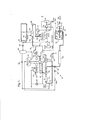
A invenção será agora ainda e mais particularmente descrita, a título de exemplo apenas, e com referência ao desenho anexo, que mostra um diagrama de fluxo esquemático de uma instalação de conversão de gás-em- líquido e equipamento associado.The invention will now be further and more particularly described, by way of example only, and with reference to the accompanying drawing, which shows a schematic flow diagram of a gas-to-liquid conversion facility and associated equipment.
A invenção refere-se a um processo químico para a conversão de gás natural (principalmente metano) para hidrocarbonetos de cadeia mais longa. Ele é apropriado para tratamento de gás associado, que é o gás natural que é produzido junto com o petróleo bruto, e é, então, separado do petróleo bruto. O primeiro estágio do processo químico envolve a formação de gás de síntese, por exemplo, por meio de reforma a vapor, por uma reação do tipo:
Esta reação é endotérmica, e pode ser catalisada por um catalisador de ródio ou platina/ródio em um primeiro canal de fluxo de gás. O calor necessário para causar esta reação pode ser fornecido por combustão catalítica 25 de um gás tal como metano ou hidrogênio, que é exotérmica, de um canal adjacente, ou por troca térmica com os gases de exaustão de um reator de combustão separado. A combustão pode ser catalisada por um catalisador de paládio em um segundo canal de fluxo de gás adjacente em um reator catalítico compacto. Em ambos os casos, o catalisador pode estar sobre um suporte de alumina estabilizada, que forma um revestimento, tipicamente menor do que 100 μm de espessura sobre um substrato metálico. Altemativamente, o catalisador pode ser aplicado nas paredes dos canais de fluxo ou pode ser 5 fornecido como grânulos dentro do canal de fluxo. O calor gerado pela combustão seria conduzido através da chapa metálica separando os canais adjacentes.This reaction is endothermic, and can be catalyzed by a rhodium or platinum / rhodium catalyst in a first gas flow channel. The heat required to cause this reaction can be provided by catalytic combustion of a gas such as methane or hydrogen, which is exothermic, from an adjacent channel, or by thermal exchange with the exhaust gases from a separate combustion reactor. Combustion can be catalyzed by a palladium catalyst in a second adjacent gas flow channel in a compact catalytic reactor. In both cases, the catalyst can be on a stabilized alumina support, which forms a coating, typically less than 100 µm thick on a metallic substrate. Alternatively, the catalyst can be applied to the walls of the flow channels or can be supplied as granules within the flow channel. The heat generated by combustion would be conducted through the metal plate separating the adjacent channels.
A mistura de gás produzida pela reforma vapor/metano é então usada para realizar uma síntese de Fischer-Tropsch para gerar um 10 hidrocarboneto de cadeia mais longa, isto é:
Referindo-se à figura 1, mostra-se uma instalação de conversão de gás-em-líquido 10 da presente invenção. A alimentação de gás natural 5 consiste principalmente de metano, mas com pequenas proporções de outros hidrocarbonetos gasosos, vapores de hidrocarboneto e vapor d’água. A alimentação de gás 5 pode estar, por exemplo, a uma pressão de 4,0 MPa (40 atm) e 35°C, seguindo por resfriamento com água do mar a uma temperatura inicial de 90°C e pode constituir o gás associado de um poço produzindo petróleo bruto. A alimentação de gás natural 5 é primeiro passada através de 5 um coalescedor 12, que remove quaisquer gotículas. Uma quantidade pequena de oxigenatos (primariamente etanol e metanol, e marcado "álcool") é então pulverizado na alimentação de gás 5, a um injetor 14, e a alimentação de gás 5 é então passada através de um trocador de calor 15 para resfriamento e, então, através uma válvula de regulação 16 através da qual ela expande em uma 10 região de pressão menor (tipicamente a cerca de 1 MPa) adiabaticamente, sem entrada significante de calor a partir do ambiente. Consequentemente, de acordo com o efeito Joule Thomson, o gás natural é consideravelmente resfriado, por exemplo, a -18°C. A corrente resultante resfriada é então alimentada a um separador de fase 18, assim produzindo uma fase de gás 20, 15 uma fase de hidrocarboneto líquido 21, e uma fase aquosa 22 (contendo os oxigenatos). O uso dos oxigenatos assegura hidratos contendo metano não sejam produzidos. Todos as três destas correntes fluidas são passadas através do trocador de calor 15, de modo a resfriar a alimentação de gás 5 fluindo para dentro.Referring to figure 1, a gas-to-
A fase de hidrocarboneto líquido 21 constitui parte da corrente de saída do produto de hidrocarboneto líquido a partir da instalação 10.The liquid hydrocarbon phase 21 forms part of the outlet stream of the liquid hydrocarbon product from the
A fase de gás 20 é então submetida a pré-tratamento 25, que pode compreender um ou mais dos seguintes: mudança de sua pressão, mudança de sua temperatura, e remoção de impurezas tais como enxofre. Então, ela é 25 misturada com vapor de água em um misturador 26.The
A mistura de gás/vapor, preferivelmente a uma temperatura de cerca de 450°C, é então alimentada em um reformador de vapor/metano catalítico 30. O reformador 30 consiste de um reator catalítico compacto formado a partir de uma pilha de placas que definem dois conjuntos de canais dispostos alternadamente. Um conjunto de canais é para a reação de reforma, e contêm um catalisador de reforma sobre suportes de folha metálica ondulada 5 removível, enquanto que o outro conjunto de canais é para a provisão de calor.The gas / steam mixture, preferably at a temperature of about 450 ° C, is then fed into a steam /
Neste exemplo, o calor é fornecido usando um queimador separado 32, os gases de exaustão do queimador 32 a cerca de 850°C sendo passados através do reformador 30 em contra-corrente para o fluxo da mistura vapor/metano. Os canais de reação do reformador 30 podem conter um 10 catalisador de níquel em uma parte inicial do canal, de comprimento entre 100 e 200 mm, por exemplo, 150 mm, a partir de um comprimento total do canal de reação de 600 mm. Na primeira parte do canal, em que o catalisador de níquel está presente, pré-reforma ocorre, portanto, quaisquer hidrocarbonetos superiores irão reagir com vapor para produzir metano. O restante do 15 comprimento dos canais de reação contém um catalisador reformador, por exemplo, um catalisador de platina/ródio, onde o vapor e metano reagem para formar monóxido de carbono e hidrogênio.In this example, heat is supplied using a
O calor para a reação de reforma a vapor/metano no reformador 30 é fornecido por combustão de um gás combustível a partir de um coletor de 20 combustível 34 em uma corrente de ar de combustão. Neste exemplo, o gás combustível é primariamente hidrogênio. O ar de combustão é fornecido por um soprador 36 e é pré-aquecido em um trocador de calor 38, retirando calor dos gases de exaustão quentes a partir da combustão, depois de terem passado através do reformador 30. Além disso, uma mistura de vapor e vapor de álcool •25 40 é introduzida no ar de combustão a montante do queimador 32. Após passar através do trocador de calor 38 os gases de exaustão podem ser ventilados através de uma chaminé 39.The heat for the steam / methane reform reaction in
Uma mistura de monóxido de carbono e de hidrogênio a acima de 800°C emerge do reformador 30, e é resfriada bruscamente a abaixo de 400°C por passagem através de um trocador de calor com elevação de vapor 42 na forma de urn termossifao. O trocador de calor 42 é um trocador de calor de tubo e envoltório, os gases quentes passando através dos tubos, e com dutos de 5 entrada e de saída se comunicando com o envoltório no topo e no fundo e se comunicando com um tambor de vapor 44. O tambor de vapor 44 está cheio em cerca de metade com água, e assim água circula através de convecção natural entre o trocador de calor 42 e o tambor de vapor 44. O vapor resultante do tambor de vapor 44 é fornecido ao misturador 26 através de uma válvula de 10 controle 46.A mixture of carbon monoxide and hydrogen at above 800 ° C emerges from
A mistura de gás, que é uma forma de gás de síntese, pode ser submetida a um resfriamento adicional (não mostrado). Ela é então submetida a compressão, usando dois compressores sucessivos 50, preferivelmente com estágios de resfriamento e de separação de líquido (não mostrados) após cada 15 compressor 50. Os compressores 50 elevam a pressão a cerca de 2,5 MPa (25 atm).The gas mixture, which is a form of synthesis gas, can be subjected to additional cooling (not shown). It is then subjected to compression, using two successive 50 compressors, preferably with cooling and liquid separation stages (not shown) after each
Será notado a partir da equação (1) acima, que a razão de hidrogênio para CO produzido desta forma é de cerca de 3:1, enquanto que a exigência estequiométrica é de cerca de 2:1, como é evidente a partir da 20 equação (2). O gás de síntese em alta pressão é, portanto, passado através de uma membrana permeável a hidrogênio 52 para remover excesso de hidrogênio. Este hidrogênio é fornecido para o coletor de combustível 34, e é o gás combustível principal.It will be noted from equation (1) above, that the ratio of hydrogen to CO produced in this way is about 3: 1, while the stoichiometric requirement is about 2: 1, as is evident from equation 20 (two). The high-pressure synthesis gas is therefore passed through a hydrogen-permeable membrane 52 to remove excess hydrogen. This hydrogen is supplied to the
A corrente de monóxido de carbono e hidrogênio em alta pressão é então aquecida a cerca de 200°C em um trocador de calor 54, e então alimentada para um reator de Fischer-Tropsch catalítico 55, este novamente sendo um reator catalítico compacto formado a partir de uma pilha de placas, como descrito acima, a mistura de reagente escoa através de um conjunto de canais, enquanto que um líquido refrigerante flui através do outro conjunto. O líquido refrigerante é circulado por uma bomba 56 e através de um trocador de calor 58. A reação de Fischer-Tropsch ocorre a cerca de 210°C, e o líquido 5 refrigerante é circulado a uma taxa tal que a temperatura varia em menos de 10 K em passagem através do reator 55.The high pressure stream of carbon monoxide and hydrogen is then heated to about 200 ° C in a heat exchanger 54, and then fed to a catalytic Fischer-
Os produtos de reação a partir da síntese de Fischer-Tropsch, predominantemente água e hidrocarbonetos, como parafinas, são resfriados a cerca de 70°C para condensar os líquidos por passagem através de um trocador 10 de calor 60 e alimentados a uma câmara de separação 62 em que as três fases água, hidrocarbonetos e gases residuais separam. A fase aquosa contém água com cerca de 1% -2 oxigenatos tais como etanol e metanol, que são formadas por meio da síntese de Fischer-Tropsch. A maior parte da fase aquosa a partir da câmara de separação 62 é tratada por extração com vapor 63 para separar os 15 oxigenatos (marcado "álcool") para deixar água limpa que pode ser descarregada para refugo. Os oxigenatos separadas, que estão a uma concentração de oxigenatos de cerca de 80%, são injetados no injetor 14 a montante da válvula de regulação 16, como descrito acima. O restante da fase aquosa é alimentado como água de processo através do trocador de calor 58, e, 20 portanto, através de uma válvula de queda de pressão 64, para um tanque de extração 66. No tanque de extração 66, a fase aquosa ferve, tipicamente a uma pressão de cerca de 10,0 MPa (10 atm), a fase líquida sendo alimentada a partir do fundo do tanque de extração 66 para o tambor de vapor 44, enquanto que a fase de vapor, que contém vapor e o grosso dos oxigenatos, fornece a corrente ■ 25 40, que é introduzida no ar de combustão por meio de uma válvula de controle 68.The reaction products from the Fischer-Tropsch synthesis, predominantly water and hydrocarbons, such as paraffins, are cooled to about 70 ° C to condense liquids by passing through a
A fase de hidrocarboneto a partir da câmara de separação 62 é o produto de hidrocarboneto de cadeia mais longa. A fase de vapor e gás a partir da câmara de separação 62 é alimentada através de dois trocadores de calor de resfriamento sucessivos 70, dos quais o segundo resfria os vapores até temperatura ambiente. Os líquidos que se condensam na passagem através do primeiro trocador de calor 70 são alimentados de volta para a câmara de 5 separação 62. A saída do segundo trocador de calor 70 é alimentada em uma câmara de separação de fase 72, onde a água e produto de hidrocarboneto leve liquido se separam.The hydrocarbon phase from the
A fase de vapor restante, que está na mesma pressão que o reator de Fischer-Tropsch 55, é então passada através de um trocador de calor 74 para 10 uma válvula de regulação 76, seguido por um vaso de separação de fase 78. À medida que o gás passa através da válvula de regulação 76, ele se expande em uma região de baixa pressão adiabaticamente, sem entrada de calor significante a partir do meio ambiente. Consequentemente, de acordo com o efeito Joule Thomson, o gás é resfriado consideravelmente. Os líquidos que emergem do 15 vaso de separação de fase 78 contém água e produto de hidrocarboneto leve. Os gases que emergem do vaso de separação de fase 78, que são os gases residuais do processo de Fischer-Tropsch, são passados de volta através do trocador de calor 74, para resfriar os gases de fluxo entrando e, opcionalmente, através de uma membrana permeável a hidrogênio (não mostrada). Uma parte do gás 20 residual pode ser alimentada de volta para a corrente de gás de síntese a montante do primeiro compressor 50. Pelo menos parte do gás residual é fornecida para o coletor de combustível 34, para garantir que não ocorra um acúmulo excessivo de metano no reator de Fischer-Tropsch 55.The remaining vapor phase, which is at the same pressure as the Fischer-
O coletor de combustível 34 não apenas fornece o combustível para o queimador 32, mas também fornece combustível por meio de um compressor de combustível 80 para uma turbina a gás 82. De fato, gás combustível comprimido também pode ser fornecido a outros equipamentos (não mostrados), que não fazem parte da instalação 10, A turbina a gás 82 pode ser disposta de modo a fornecer energia elétrica para a operação da instalação 10. Como indicado por uma linha tracejado na figura, neste exemplo, a energia elétrica gerada pela turbina a gás 82 é usada para acionar os compressores 5 50. Altemativamente, a turbina a gás 82 pode ser diretamente acoplada para acionar o compressor 50.
Será apreciado que no processo acima descrito, o calor produzido pela reação de Fischer-Tropsch é usado para a ebulição de vapor e álcool no tanque de extração 66, e assim é transferido para os canais de combustão 10 através da alimentação 40. O calor restante requerido para reforma é provido pelo gás combustível a partir do coletor de combustível 34 sofrendo combustão no queimador 32. Este pode ser um queimador de duto, na qual existem vários bicos através dos quais o gás combustível é alimentado a uma corrente de ar de combustão, de modo que ele queima com um flare. Altemativamente, o 15 queimador 32 pode ser uma unidade de combustão catalítica sem chamas. Como mencionado previamente, o gás de exaustão quente resultante fornece calor ao reformador 30, e é então usado para pré-aquecer ar de combustão no trocador de calor 38.It will be appreciated that in the process described above, the heat produced by the Fischer-Tropsch reaction is used for the boiling of steam and alcohol in the
Em uma modificação do processo acima descrito, o ar de 20 combustão pode ser adicionalmente pré-aquecido por introdução de hidrogênio no ar de combustão, e passando o mesmo através de uma estrutura de colméia de um aço ferrítico contendo alumínio, como Fecralloy, com uma superfície oxidada, que foi verificada ser catalítica para combustão de hidrogênio. Altemativamente, o pré-aquecimento pode ser realizado usando um 25 queimador de duto, em que um combustível como hidrogênio é queimado. O aquecimento final do ar de combustão até à temperatura desejada na proximidade de 800°C, então, pode ser conseguida usando queimador de duto 32 ao qual uma corrente de gás combustível é provida, tal como o gás residual a partir do processo de Fischer-Tropsch, ou como descrito acima, usando um queimador 32 que é uma unidade de combustão catalítica sem chama.In a modification of the process described above, the combustion air can be additionally preheated by introducing hydrogen into the combustion air, and passing it through a honeycomb structure of aluminum-containing ferritic steel, such as Fecralloy, with a oxidized surface, which has been found to be catalytic for hydrogen combustion. Alternatively, preheating can be carried out using a duct burner, in which a fuel such as hydrogen is burned. The final heating of the combustion air to the desired temperature in the vicinity of 800 ° C, then, can be achieved using
Em outra modificação, o ar de combustão é pré-aquecido, quer por passagem através de um queimador de duto alimentado com um combustível 5 apropriado, quer através da introdução de hidrogênio no ar de combustão, e passando o mesmo através de uma estrutura de colméia de aço ferrítico contendo alumínio, como descrito acima, de modo que hidrogênio sofre combustão catalítica. O ar de combustão quente é então alimentado em um reator de combustão/reforma integrado, e um combustível como metano ou gás 10 residual é introduzido e submetido à combustão catalítica em canais do reator fornecendo calor, através dos quais o ar de combustão quente escoa. Nesta modificação a combustão catalítica pode, por exemplo, ocorrer sobre um catalisador de paládio/platina dentro dos canais fornecendo calor dentro do reator de reforma 30. Neste caso, o percurso do gás de combustão é 15 preferivelmente co-corrente com relação ao percurso do gás do reformador. O catalisador pode incluir gama-alumina como um suporte, revestido com uma mistura 3:Ide paládio/platina, que é um catalisador eficaz sobre uma ampla faixa de temperaturas. A mistura de gás combustível pode ser fornecida em estágios ao longo do reator 30 para assegurar que a combustão ocorre em todo 20 o comprimento dos canais de combustão.In another modification, the combustion air is preheated, either by passing through a duct burner fed with an appropriate fuel, or by introducing hydrogen into the combustion air, and passing it through a honeycomb structure. of ferritic steel containing aluminum, as described above, so that hydrogen undergoes catalytic combustion. The hot combustion air is then fed into an integrated combustion / reform reactor, and a fuel such as methane or
Claims (14)
Applications Claiming Priority (3)
| Application Number | Priority Date | Filing Date | Title |
|---|---|---|---|
| GB201007196A GB201007196D0 (en) | 2010-04-30 | 2010-04-30 | Gas-to-liquid technology |
| GB1007196.7 | 2010-04-30 | ||
| PCT/GB2011/050831 WO2011135357A1 (en) | 2010-04-30 | 2011-04-27 | Gas-to-liquid technology |
Publications (2)
| Publication Number | Publication Date |
|---|---|
| BR112012025792A2 BR112012025792A2 (en) | 2016-09-13 |
| BR112012025792B1 true BR112012025792B1 (en) | 2021-04-13 |
Family
ID=42289846
Family Applications (1)
| Application Number | Title | Priority Date | Filing Date |
|---|---|---|---|
| BR112012025792-7A BR112012025792B1 (en) | 2010-04-30 | 2011-04-27 | INSTALLATION, AND, GAS-IN-LIQUID CONVERSION PROCESS FOR TREATMENT OF NATURAL GAS |
Country Status (15)
| Country | Link |
|---|---|
| US (2) | US8945488B2 (en) |
| EP (1) | EP2564140B1 (en) |
| JP (1) | JP5868951B2 (en) |
| KR (1) | KR20130060225A (en) |
| CN (1) | CN103221769B (en) |
| AU (1) | AU2011247103B2 (en) |
| BR (1) | BR112012025792B1 (en) |
| CA (1) | CA2793682A1 (en) |
| DK (1) | DK2564140T3 (en) |
| EA (1) | EA023199B1 (en) |
| GB (1) | GB201007196D0 (en) |
| MX (1) | MX2012011675A (en) |
| NO (1) | NO2564140T3 (en) |
| TW (1) | TW201200234A (en) |
| WO (1) | WO2011135357A1 (en) |
Families Citing this family (14)
| Publication number | Priority date | Publication date | Assignee | Title |
|---|---|---|---|---|
| GB201120327D0 (en) * | 2011-11-24 | 2012-01-04 | Compactgtl Plc | Oil well product treatment |
| GB201216271D0 (en) * | 2012-09-12 | 2012-10-24 | Compactgtl Plc | Operation of catalytic process plant |
| EP2845837A1 (en) * | 2013-09-09 | 2015-03-11 | Casale SA | Process and plant for the production of ammonia make-up gas including production of a hydrogen gas by steam reforming |
| DE102014007470A1 (en) * | 2013-11-15 | 2015-05-21 | Linde Aktiengesellschaft | Process and apparatus for steam reforming and steam cracking of hydrocarbons |
| US20150299596A1 (en) * | 2014-03-12 | 2015-10-22 | Rustam H. Sethna | Methods for removing contaminants from natural gas |
| US9843062B2 (en) | 2016-03-23 | 2017-12-12 | Energyield Llc | Vortex tube reformer for hydrogen production, separation, and integrated use |
| US9840413B2 (en) | 2015-05-18 | 2017-12-12 | Energyield Llc | Integrated reformer and syngas separator |
| RU2733386C2 (en) * | 2015-10-09 | 2020-10-01 | Стюарт Л. ФЕНИКС | Method and system for extracting hard-to-reach gas from underwater media, conversion thereof into clathrates and safe transportation for consumption |
| JP6264622B2 (en) * | 2016-04-18 | 2018-01-24 | 株式会社ソディック | Additive manufacturing equipment |
| PL3267100T3 (en) * | 2016-07-08 | 2021-10-25 | L'Air Liquide Société Anonyme pour l'Etude et l'Exploitation des Procédés Georges Claude | Steam creation system |
| US10870810B2 (en) * | 2017-07-20 | 2020-12-22 | Proteum Energy, Llc | Method and system for converting associated gas |
| US11717784B1 (en) | 2020-11-10 | 2023-08-08 | Solid State Separation Holdings, LLC | Natural gas adsorptive separation system and method |
| US11577191B1 (en) | 2021-09-09 | 2023-02-14 | ColdStream Energy IP, LLC | Portable pressure swing adsorption method and system for fuel gas conditioning |
| GB202216857D0 (en) * | 2022-11-11 | 2022-12-28 | Johnson Matthey Davy Technologies Ltd | A method of forming a liquid hydrocarbon product |
Family Cites Families (20)
| Publication number | Priority date | Publication date | Assignee | Title |
|---|---|---|---|---|
| US2472219A (en) * | 1945-02-13 | 1949-06-07 | Standard Oil Co | Synthesis of hydrocarbons |
| GB1011453A (en) | 1964-01-23 | 1965-12-01 | Conch Int Methane Ltd | Process for liquefying natural gas |
| JPS54103797A (en) | 1978-02-03 | 1979-08-15 | Sumitomo Heavy Ind Ltd | H2 separation and purification from h2 containing gas |
| US4932213A (en) | 1989-02-10 | 1990-06-12 | Amoco Corporation | Method of treating natural gas to remove ethane and higher hydrocarbons |
| CA1316547C (en) | 1989-02-10 | 1993-04-20 | Frank J. Reintjes | Process for recovering natural gas liquids |
| RU2144556C1 (en) * | 1995-06-07 | 2000-01-20 | Элкор Корпорейшн | Method of gas flow separation and device for its embodiment |
| NO312921B1 (en) * | 1999-07-05 | 2002-07-15 | Sinvent As | Multitest compilation for evaluation, detection and monitoring of processes at elevated pressure |
| US7300635B2 (en) | 2000-01-11 | 2007-11-27 | Compactgtl Plc | Catalytic reactor |
| US6581409B2 (en) * | 2001-05-04 | 2003-06-24 | Bechtel Bwxt Idaho, Llc | Apparatus for the liquefaction of natural gas and methods related to same |
| US7594414B2 (en) | 2001-05-04 | 2009-09-29 | Battelle Energy Alliance, Llc | Apparatus for the liquefaction of natural gas and methods relating to same |
| GB0116894D0 (en) | 2001-07-11 | 2001-09-05 | Accentus Plc | Catalytic reactor |
| US6743829B2 (en) * | 2002-01-18 | 2004-06-01 | Bp Corporation North America Inc. | Integrated processing of natural gas into liquid products |
| RU2310677C2 (en) | 2002-12-02 | 2007-11-20 | КОМПАКТДЖТЛ ПиЭлСи | Catalytic reactor and process |
| TW200636198A (en) | 2004-12-30 | 2006-10-16 | Twister Bv | Throttling valve and method for enlarging liquid droplet sizes in a fluid stream flowing therethrough |
| WO2007018677A1 (en) * | 2005-07-26 | 2007-02-15 | Exxonmobil Upstream Research Company | Method of purifying hydrocarbons and regeneration of adsorbents used therein |
| US7437889B2 (en) * | 2006-01-11 | 2008-10-21 | Air Products And Chemicals, Inc. | Method and apparatus for producing products from natural gas including helium and liquefied natural gas |
| GB0608277D0 (en) * | 2006-04-27 | 2006-06-07 | Accentus Plc | Process for preparing liquid hydrocarbons |
| US9296966B2 (en) * | 2006-07-06 | 2016-03-29 | Fluor Technologies Corporation | Propane recovery methods and configurations |
| KR100890041B1 (en) * | 2006-12-29 | 2009-03-25 | 주식회사 하이닉스반도체 | Clock buffer circuit of semiconductor device |
| CA2675816C (en) * | 2007-01-19 | 2015-09-01 | Velocys, Inc. | Process and apparatus for converting natural gas to higher molecular weight hydrocarbons using microchannel process technology |
-
2010
- 2010-04-30 GB GB201007196A patent/GB201007196D0/en not_active Ceased
-
2011
- 2011-04-27 CN CN201180021512.0A patent/CN103221769B/en active Active
- 2011-04-27 WO PCT/GB2011/050831 patent/WO2011135357A1/en active Application Filing
- 2011-04-27 EA EA201291145A patent/EA023199B1/en not_active IP Right Cessation
- 2011-04-27 JP JP2013506751A patent/JP5868951B2/en not_active Expired - Fee Related
- 2011-04-27 US US13/638,009 patent/US8945488B2/en active Active
- 2011-04-27 NO NO11720572A patent/NO2564140T3/no unknown
- 2011-04-27 AU AU2011247103A patent/AU2011247103B2/en active Active
- 2011-04-27 KR KR20127031275A patent/KR20130060225A/en not_active Application Discontinuation
- 2011-04-27 DK DK11720572.4T patent/DK2564140T3/en active
- 2011-04-27 EP EP11720572.4A patent/EP2564140B1/en active Active
- 2011-04-27 CA CA 2793682 patent/CA2793682A1/en active Pending
- 2011-04-27 BR BR112012025792-7A patent/BR112012025792B1/en active IP Right Grant
- 2011-04-27 MX MX2012011675A patent/MX2012011675A/en unknown
- 2011-04-29 TW TW100115077A patent/TW201200234A/en unknown
-
2014
- 2014-12-22 US US14/578,569 patent/US9382115B2/en not_active Expired - Fee Related
Also Published As
| Publication number | Publication date |
|---|---|
| AU2011247103B2 (en) | 2016-09-29 |
| AU2011247103A2 (en) | 2012-10-25 |
| CN103221769B (en) | 2015-08-12 |
| US20150119478A1 (en) | 2015-04-30 |
| EP2564140A1 (en) | 2013-03-06 |
| TW201200234A (en) | 2012-01-01 |
| EA201291145A1 (en) | 2013-06-28 |
| NO2564140T3 (en) | 2018-07-28 |
| US9382115B2 (en) | 2016-07-05 |
| EP2564140B1 (en) | 2018-02-28 |
| JP5868951B2 (en) | 2016-02-24 |
| BR112012025792A2 (en) | 2016-09-13 |
| GB201007196D0 (en) | 2010-06-16 |
| JP2013531693A (en) | 2013-08-08 |
| WO2011135357A1 (en) | 2011-11-03 |
| AU2011247103A1 (en) | 2012-10-11 |
| CN103221769A (en) | 2013-07-24 |
| CA2793682A1 (en) | 2011-11-03 |
| DK2564140T3 (en) | 2018-05-28 |
| MX2012011675A (en) | 2012-11-16 |
| KR20130060225A (en) | 2013-06-07 |
| EA023199B1 (en) | 2016-05-31 |
| US8945488B2 (en) | 2015-02-03 |
| US20130041049A1 (en) | 2013-02-14 |
Similar Documents
| Publication | Publication Date | Title |
|---|---|---|
| BR112012025792B1 (en) | INSTALLATION, AND, GAS-IN-LIQUID CONVERSION PROCESS FOR TREATMENT OF NATURAL GAS | |
| JP5048054B2 (en) | Method for producing liquid hydrocarbon | |
| US8926866B2 (en) | Hydrogen generating apparatus using steam reforming reaction | |
| MXPA04005959A (en) | Production enhancement for a reactor. | |
| US7351750B2 (en) | Method for producing long-chain hydrocarbons from natural gas | |
| US20060135630A1 (en) | Producing longer-chain hydrocarbons from natural gas | |
| AU2012342258B2 (en) | Oil well product treatment | |
| EP2787060A1 (en) | System or method for producing gasoline or dimethyl ether | |
| JPH06256239A (en) | Production of methanol | |
| WO2013108525A1 (en) | System and method for producing gasoline | |
| BRPI0618102A2 (en) | steam generation method and apparatus | |
| WO2023139258A1 (en) | Conversion of co2 and h2 to syngas | |
| CN117440926A (en) | For CO 2 Heat exchange reactor for conversion | |
| CN117425618A (en) | Heat exchange reactor with reduced metal dusting | |
| WO2014041332A1 (en) | Operation of catalytic process plant |
Legal Events
| Date | Code | Title | Description |
|---|---|---|---|
| B25D | Requested change of name of applicant approved |
Owner name: COMPACTGTL LIMITED (GB) |
|
| B06F | Objections, documents and/or translations needed after an examination request according [chapter 6.6 patent gazette] | ||
| B06U | Preliminary requirement: requests with searches performed by other patent offices: procedure suspended [chapter 6.21 patent gazette] | ||
| B06A | Patent application procedure suspended [chapter 6.1 patent gazette] | ||
| B09A | Decision: intention to grant [chapter 9.1 patent gazette] | ||
| B16A | Patent or certificate of addition of invention granted [chapter 16.1 patent gazette] |
Free format text: PRAZO DE VALIDADE: 20 (VINTE) ANOS CONTADOS A PARTIR DE 27/04/2011, OBSERVADAS AS CONDICOES LEGAIS. |