BR112012007964B1 - CARDBOARD WITH RE-CLOSED PLASTIC COVER - Google Patents
CARDBOARD WITH RE-CLOSED PLASTIC COVER Download PDFInfo
- Publication number
- BR112012007964B1 BR112012007964B1 BR112012007964-6A BR112012007964A BR112012007964B1 BR 112012007964 B1 BR112012007964 B1 BR 112012007964B1 BR 112012007964 A BR112012007964 A BR 112012007964A BR 112012007964 B1 BR112012007964 B1 BR 112012007964B1
- Authority
- BR
- Brazil
- Prior art keywords
- zipper
- fold
- package
- semi
- lid
- Prior art date
Links
- 229920003023 plastic Polymers 0.000 title abstract description 10
- 239000004033 plastic Substances 0.000 title abstract description 9
- 239000011111 cardboard Substances 0.000 title description 5
- 238000005304 joining Methods 0.000 claims description 2
- 238000004519 manufacturing process Methods 0.000 abstract description 10
- 239000000463 material Substances 0.000 description 80
- 210000001138 Tears Anatomy 0.000 description 23
- 238000007789 sealing Methods 0.000 description 21
- 239000003292 glue Substances 0.000 description 18
- 238000004806 packaging method and process Methods 0.000 description 17
- 239000000853 adhesive Substances 0.000 description 8
- 230000001070 adhesive Effects 0.000 description 8
- 239000000789 fastener Substances 0.000 description 5
- 230000000875 corresponding Effects 0.000 description 4
- 238000010586 diagram Methods 0.000 description 4
- 238000007906 compression Methods 0.000 description 3
- 238000001514 detection method Methods 0.000 description 3
- 239000000945 filler Substances 0.000 description 3
- 235000013305 food Nutrition 0.000 description 3
- 239000000123 paper Substances 0.000 description 3
- 238000004026 adhesive bonding Methods 0.000 description 2
- 230000015572 biosynthetic process Effects 0.000 description 2
- 238000010276 construction Methods 0.000 description 2
- 238000005520 cutting process Methods 0.000 description 2
- 238000005755 formation reaction Methods 0.000 description 2
- 238000000034 method Methods 0.000 description 2
- 230000000737 periodic Effects 0.000 description 2
- 239000011120 plywood Substances 0.000 description 2
- 230000002787 reinforcement Effects 0.000 description 2
- 230000000717 retained Effects 0.000 description 2
- 230000000087 stabilizing Effects 0.000 description 2
- 238000003860 storage Methods 0.000 description 2
- 239000010902 straw Substances 0.000 description 2
- 238000005728 strengthening Methods 0.000 description 2
- 238000003466 welding Methods 0.000 description 2
- 206010016322 Feeling abnormal Diseases 0.000 description 1
- 210000003284 Horns Anatomy 0.000 description 1
- -1 Polytetrafluoroethylene Polymers 0.000 description 1
- 230000003466 anti-cipated Effects 0.000 description 1
- 229920000704 biodegradable plastic Polymers 0.000 description 1
- 238000006065 biodegradation reaction Methods 0.000 description 1
- 239000000969 carrier Substances 0.000 description 1
- 235000013339 cereals Nutrition 0.000 description 1
- 239000011248 coating agent Substances 0.000 description 1
- 238000000576 coating method Methods 0.000 description 1
- 230000000295 complement Effects 0.000 description 1
- 238000005336 cracking Methods 0.000 description 1
- 239000000835 fiber Substances 0.000 description 1
- 239000011094 fiberboard Substances 0.000 description 1
- 229920002457 flexible plastic Polymers 0.000 description 1
- 235000013611 frozen food Nutrition 0.000 description 1
- 238000003475 lamination Methods 0.000 description 1
- MYMOFIZGZYHOMD-UHFFFAOYSA-N oxygen Chemical compound O=O MYMOFIZGZYHOMD-UHFFFAOYSA-N 0.000 description 1
- 229910052760 oxygen Inorganic materials 0.000 description 1
- 239000001301 oxygen Substances 0.000 description 1
- 239000011087 paperboard Substances 0.000 description 1
- 229920000642 polymer Polymers 0.000 description 1
- 229920001343 polytetrafluoroethylene Polymers 0.000 description 1
- 239000004810 polytetrafluoroethylene Substances 0.000 description 1
- 230000002035 prolonged Effects 0.000 description 1
- 230000003014 reinforcing Effects 0.000 description 1
- 239000007787 solid Substances 0.000 description 1
- 230000001360 synchronised Effects 0.000 description 1
- 229920001169 thermoplastic Polymers 0.000 description 1
- 239000004416 thermosoftening plastic Substances 0.000 description 1
- 230000001052 transient Effects 0.000 description 1
- 230000001960 triggered Effects 0.000 description 1
- 238000011144 upstream manufacturing Methods 0.000 description 1
Images


Abstract
CARTONADO COM TAMPA REFECHÁVEL DE PLÁSTICO A presente descrição se refere a um método e aparelho para fabricação de uma embalagem com um recipiente rigido ou semi-rígido e uma tampa polimérica ou plástica com um refechamento, como um zíper. O recipiente rígido ou semi-rígido é tipicamente fornecido em uma pilha de recipiente achatados. A tampa é selada, colada ou presa de algum modo aos recipientes. O recipiente, tipicamente invertido, é enchido, e o fundo é formado dobrandoCARTRIDGE WITH A PLASTIC RESEALABLE LID The present description relates to a method and apparatus for manufacturing a package with a rigid or semi-rigid container and a polymeric or plastic lid with a reseal such as a zipper. The rigid or semi-rigid container is typically supplied in a stack of flat containers. The lid is sealed, glued or otherwise secured to the containers. The container, typically inverted, is filled, and the bottom is formed by folding
Description
O presente pedido reivindica a prioridade nos termos do Artigo 35 do Código dos Estados Unidos §119(e) do pedido provisório de patente de série n° 61/249.852, depositado 5 em 8 de outubro de 2009 e do pedido provisório de patente de série n° 61/298.429, depositado em 26 de janeiro de 2010, cujos conteúdos são incorporados por citação em sua totali-dade.The present application claims priority pursuant to
A presente descrição se refere a um método e aparelho para produzir uma embala- 10 gem com um recipiente do tipo cartonado feito de papel, papelão, compensado ou material rígido ou semi-rígido similar ao qual é fixada uma seção de tampa refechável feita de plástico, polímero ou outro material flexível, a estrutura refechável sendo tipicamente um zíper, mas não está limitada a isso. A presente descrição se refere igualmente à embalagem resultante.The present description relates to a method and apparatus for producing a package with a cardboard-type container made of paper, cardboard, plywood or similar rigid or semi-rigid material to which a reclosable lid section made of plastic is attached. , polymer or other flexible material, the reclosable structure typically being a zipper, but not limited thereto. The present description also refers to the resulting packaging.
Na técnica anterior, é consagrada a produção de sacolas plásticas flexíveis re- fecháveis para a venda de gêneros alimentícios ou outros produtos para o consumidor. As sacolas ou embalagens, apesar de bem adequadas aos usos pretendidos, tipicamente não têm sido utilizadas para produtos alimentícios que facilmente seriam esmagados ou danifi- 20 cados durante a remessa. Adicionalmente, essas sacolas ou embalagem podem resultar em ineficiências no armazenamento, transporte e exibição.In the prior art, the production of resealable flexible plastic bags for the sale of foodstuffs or other consumer products is enshrined. Bags or packaging, while well suited for their intended uses, typically have not been used for food products that would easily be crushed or damaged during shipment. Additionally, these bags or packaging can result in inefficiencies in storage, transport and display.
Do mesmo modo, caixas de papelão tradicionais são bastante conhecidas na embalagem e comercialização de tais produtos bem estabelecidos, como cereais. No entanto, estas caixas tipicamente são pesadas e demandam um papel interno encerado ou forro si- 25 milar, tipicamente rasgável e, portanto, não são re-seláveis e não protegem os conteúdos após abertura inicial. Isso eleva os custos de fabricação e tipicamente não permite que a embalagem seja completamente enchida com o produto, resultando assim em ineficiências em termos de espaço, o que aumenta os custos para armazenamento, transporte e exibição do produto. Portanto, muitas destas caixas de papelão tradicionais, particularmente aquelas 30 com um forro plástico rasgável, estão abaixo do nível satisfatório quanto às suas capacidades de re-fechamento.Likewise, traditional cardboard boxes are well known for packaging and marketing such well-established products as cereals. However, these boxes are typically heavy and require an inner waxed paper or similar lining, typically tearable, and therefore are not re-sealable and do not protect the contents after initial opening. This raises manufacturing costs and typically does not allow the packaging to be completely filled with product, thus resulting in space inefficiencies, which increases costs for storing, transporting and displaying the product. Therefore, many of these traditional cardboard boxes, particularly those with a tearable plastic lining, are below the satisfactory level in their resealing capabilities.
Foram realizadas diversas tentativas nas embalagens para abordar tais deficiências, mas nenhuma delas foi totalmente satisfatória. As tentativas anteriores incluem aque-las reveladas na Patente N° U.S. 7.524.111 intitulada “Rigid-Bottoned Resealable Bag with 35 Handles”, emitida em 28 de abril de 2009 em favor de Williams; Patente N° U.S. 7.207.716 intitulada “Flexible Container Having Flat Walls”, emitida em 24 de abril de 2007 em favor de Buchanan; Patente N° U.S. 7.160.029 intitulada “Enclosure for Resealing an Package andSeveral attempts have been made on packaging to address these shortcomings, but none have been entirely satisfactory. Previous attempts include those disclosed in U.S. Patent No. 7,524,111 entitled "Rigid-Bottoned Resealable Bag with 35 Handles", issued April 28, 2009 in favor of Williams; U.S. Patent 7,207,716 entitled “Flexible Container Having Flat Walls,” issued April 24, 2007 to Buchanan; U.S. Patent No. 7,160,029 entitled "Enclosure for Resealing an Package and
Method Therefor”, emitida em 9 de janeiro de 2007 em favor de Bein; Patente N° U.S. 6.908.422 intitulada “Reclosable Packaging Bag and Method for Fabricating the Same”, emitida em 21 de junho de 2005 em favor de Ichikawa et al.; Patente N° U.S. 6.110.512 intitulada “Package and Merchandiser”, emitida em 29 de agosto de 2000 em favor de Teasdale; Patente N° U.S. 6.063.416 intitulada “Procedure and Package to Enable Peg Display of Food Pouch in Tent-Style Paperboard Carton”, emitida em 16 de maio de 2000 em favor de Teasdale et al.; Patente N° U.S. 4.691.373 intitulada “Zipper Closure with Unitary Adhesive Cover Sheet”, emitida em 1o de setembro de 1987 em favor de Ausnit; e Pedido Publicado de Patente N° U.S. 2005/0194386, intitulado “Zipper Box Covers” publicada em 8 de setembro de 2005 em favor de Shai; e Patente do Japão N° 2002104511 intitulada “Bag-in-Carton”, publicada em 10 de abril de 2002 em favor de Makoto et al.Method Therefor", issued January 9, 2007 in favor of Bein; U.S. Patent No. 6,908,422 entitled "Reclosable Packaging Bag and Method for Fabricating the Same", issued June 21, 2005 in favor of Ichikawa et al.; U.S. Patent No. 6,110,512 entitled "Package and Merchandiser", issued August 29, 2000 in favor of Teasdale; U.S. Patent No. 6,063,416 entitled "Procedure and Package to Enable Peg Display of Food Pouch in Tent-Style Paperboard Carton", issued May 16, 2000 in favor of Teasdale et al.; U.S. Patent No. 4,691,373 entitled "Zipper Closure with Unitary Adhesive Cover Sheet", issued September 1, 1987 in favor of Ausnit; and Published U.S. Patent Application No. 2005/0194386, entitled "Zipper Box Covers" published September 8, 2005 in favor of Shai; and Japanese Patent No. 2002104511 entitled "Bag-in-Carton", issued April 10, 2002 in favor of Makoto et al.
Portanto, um objetivo da presente descrição é fornecer uma embalagem refechável que tenha paredes rígidas para assim proporcionar uma embalagem de alta capacidade e eficiente em termos de espaço com uma superfície de impressão lisa, deste modo conferindo proteção para a embalagem de produtos que podem ser amassados ou delicados.Therefore, an object of the present description is to provide a reclosable package that has rigid walls to thereby provide a high-capacity, space-efficient package with a smooth print surface, thereby providing protection to the packaging of crushable products. or delicate.
Portanto, um objetivo adicional da presente descrição é proporcionar uma embalagem de baixo peso e que tipicamente seja refechável.Therefore, a further objective of the present description is to provide a package that is lightweight and typically resealable.
Estes e outros objetivos são alcançados pela presente descrição proporcionando uma embalagem, junto com um método e aparelho para a produção da mesma, o que inclui um recipiente do tipo cartonado rígido ou semi-rígido e, fixada ao mesmo, uma tampa plástica, polimérica, ou tampa flexível similar, tipicamente com uma configuração de zíper refechável, mas não limitada a isso.These and other objectives are achieved by the present description by providing a package, together with a method and apparatus for producing the same, which includes a rigid or semi-rigid carton type container and, attached thereto, a plastic, polymeric lid, or similar flexible cap, typically with a resealable zipper configuration, but not limited to.
Outros objetivos e vantagens da descrição serão evidenciados a partir da descrição adiante e dos desenhos que a acompanham, onde:Other purposes and advantages of the description will be evidenced from the description below and the accompanying drawings, where:
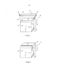
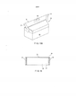
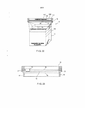
A Figura 1 é uma vista em perspectiva de uma modalidade de uma embalagem da presente descrição, mostrada em uma configuração cheia com um fundo selado e uma tampa projetada para cima.Figure 1 is a perspective view of one embodiment of a package of the present description, shown in a filled configuration with a sealed bottom and an upwardly projecting lid.
A Figura 2 é uma vista em perspectiva de uma modalidade de uma embalagem da presente descrição, mostrada em uma configuração cheia com um fundo selado e uma tampa em nivelamento.Figure 2 is a perspective view of one embodiment of a package of the present description, shown in a filled configuration with a sealed bottom and a flush cap.
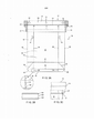
A Figura 3A é uma vista frontal plana de uma modalidade de uma embalagem da presente descrição, mostrada em uma configuração não cheia plana, com uma tampa proje-tada para cima e um fundo não selado.Figure 3A is a front plan view of one embodiment of a package of the present description, shown in a flat unfilled configuration, with an upwardly projecting lid and an unsealed bottom.
A Figura 3B é uma vista em seção transversal do material típico utilizado para a porção de recipiente rígido ou semi-rígido de modalidades da presente descrição.Figure 3B is a cross-sectional view of typical material used for the rigid or semi-rigid container portion of embodiments herein.
A Figura 3C é uma vista em perspectiva mostrando a tampa fixada ao interior da porção de recipiente da embalagem.Figure 3C is a perspective view showing the lid attached to the interior of the container portion of the package.
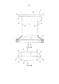
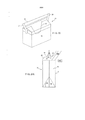
A Figura 4A é uma vista plana de uma modalidade de uma embalagem invertida da presente descrição, mostrando o fundo parcialmente dobrado, tipicamente depois do enchi-mento do fundo, com o selo do tipo “fin sear do fundo apontando para cima.Figure 4A is a plan view of one embodiment of an inverted package of the present description, showing the bottom partially folded, typically after bottom filling, with the bottom fin seal pointing upwards.
A Figura 4B é uma vista plana a partir de cima da modalidade da embalagem invertida da Figura 4A.Figure 4B is a top plan view of the inverted package embodiment of Figure 4A.
A Figura 5A é uma vista plana de uma modalidade de uma embalagem invertida da presente descrição, mostrando o fundo parcialmente dobrado, tipicamente depois do enchi-mento do fundo, com o selo do tipo “fin sear do fundo dobrado em nivelamento com o fundo da embalagem.Figure 5A is a plan view of one embodiment of an inverted package of the present description, showing the bottom partially folded, typically after bottom filling, with the folded bottom fin seal type flush with the bottom of the packaging.
A Figura 5B é uma vista plana observada de cima da modalidade da embalagem invertida da Figura 5 A.Figure 5B is a top plan view of the inverted package embodiment of Figure 5A.
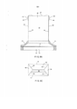
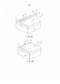
A Figura 6A é uma vista plana de uma modalidade de uma embalagem invertida da presente descrição, similar à Figura 1, mostrando as orelhas do fundo dobradas de encontro aos lados da embalagem e seladas aos mesmos, tipicamente depois do enchimento do fundo.Figure 6A is a plan view of one embodiment of an inverted package of the present description, similar to Figure 1, showing the bottom ears folded against the sides of the package and sealed thereto, typically after bottom filling.
A Figura 6B é uma vista plana lateral da modalidade da embalagem invertida da Figura 5A.Figure 6B is a side plan view of the inverted package embodiment of Figure 5A.
A Figura 6C é uma vista do fundo de uma modalidade da embalagem, mostrada com as orelhas dobradas e seladas ao fundo da embalagem.Figure 6C is a bottom view of one embodiment of the carton, shown with the ears folded and sealed to the bottom of the carton.
A Figura 6D é uma vista em seção transversal de uma modalidade da embalagem, mostrada com aletas sobre os painéis dianteiro e traseiro para a fixação interna da porção da tampa.Figure 6D is a cross-sectional view of one embodiment of the carton, shown with fins on the front and back panels for internally securing the lid portion.
A Figura 6E é uma vista lateral de uma modalidade adicional da embalagem da presente descrição.Figure 6E is a side view of a further embodiment of the package of the present description.
A Figura 6F é uma vista em perspectiva mostrando a modalidade da embalagem da Figura 6E, com uma tampa dobrada.Figure 6F is a perspective view showing the embodiment of the Figure 6E package, with a folded lid.
A Figura 6G é uma vista lateral de outra modalidade adicional da embalagem da presente descrição.Figure 6G is a side view of another additional embodiment of the package of the present description.
A Figura 6H é uma vista em perspectiva mostrando a modalidade da embalagem da Figura 6G, com uma tampa dobrada.Figure 6H is a perspective view showing the embodiment of the Figure 6G package with a folded lid.
A Figura 7 é uma vista em perspectiva do topo da porção de recipiente rígido ou semi-rígido de uma modalidade da embalagem da presente descrição, mostrando um raio ou chanfradura formada nos cantos da mesma.Figure 7 is a top perspective view of the rigid or semi-rigid container portion of one embodiment of the package of the present description, showing a spoke or chamfer formed at the corners thereof.
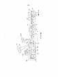
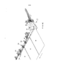
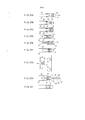
A Figura 8A é uma vista esquemática de uma primeira modalidade de um método e aparelho para produzir a embalagem da presente descrição antes do enchimento.Figure 8A is a schematic view of a first embodiment of a method and apparatus for producing the package of the present description prior to filling.
A Figura 8B é uma vista esquemática de uma segunda modalidade de um método e aparelho para produzir a embalagem da presente descrição antes do enchimento, que compreende adicionalmente uma porção em linhas invisíveis para ilustrar outra variação.Figure 8B is a schematic view of a second embodiment of a method and apparatus for producing the package of the present description before filling, which further comprises a portion in phantom lines to illustrate another variation.
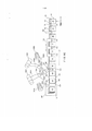
A Figura 8C é uma vista esquemática de uma terceira modalidade de um método e aparelho para produzir a embalagem da presente descrição antes do enchimento.Figure 8C is a schematic view of a third embodiment of a method and apparatus for producing the package of the present description prior to filling.
A Figura 8D é uma vista esquemática de uma quarta modalidade de um método e aparelho para produzir a embalagem da presente descrição antes do enchimento.Figure 8D is a schematic view of a fourth embodiment of a method and apparatus for producing the package of the present disclosure prior to filling.
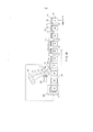
A Figura 8E é uma vista esquemática de uma quinta modalidade de um método e aparelho para produzir a embalagem da presente descrição antes do enchimento.Figure 8E is a schematic view of a fifth embodiment of a method and apparatus for producing the package of the present description prior to filling.
A Figura 8F é uma vista esquemática de uma sexta modalidade de um método e aparelho para produzir a embalagem da presente descrição antes do enchimento.Figure 8F is a schematic view of a sixth embodiment of a method and apparatus for producing the package of the present disclosure prior to filling.
A Figura 8G é uma vista lateral da sexta modalidade (vide a Figura 8F) de um método e aparelho para produzir a embalagem da presente descrição antes do enchimento.Figure 8G is a side view of the sixth embodiment (see Figure 8F) of a method and apparatus for producing the package of the present description prior to filling.
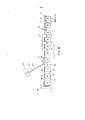
A Figura 9A é uma vista esquemática de uma sétima modalidade de um método e aparelho para produzir a embalagem da presente descrição antes do enchimento.Figure 9A is a schematic view of a seventh embodiment of a method and apparatus for producing the package of the present description prior to filling.
A Figura 9B é uma vista esquemática de uma oitava modalidade de um método e aparelho para produzir a embalagem da presente descrição antes do enchimento.Figure 9B is a schematic view of an eighth embodiment of a method and apparatus for producing the package of the present disclosure prior to filling.
A Figura 9C é uma vista esquemática de uma nona modalidade de um método e aparelho para produzir a embalagem da presente descrição antes do enchimento.Figure 9C is a schematic view of a ninth embodiment of a method and apparatus for producing the package of the present description prior to filling.
A Figura 10 é uma vista em perspectiva de uma modalidade do aparelho ultrassónico utilizado para formar os selos transversais em um aspecto de uma modalidade do método e aparelho para produzir a embalagem.Figure 10 is a perspective view of an embodiment of ultrasonic apparatus used to form the cross seals in one aspect of an embodiment of the method and apparatus for producing the package.
A Figura 11 é uma vista em perspectiva de um aparelho ultrassónico utilizado para formar três selos transversais simultaneamente em um aspecto de uma modalidade do método e aparelho para produzir a embalagem.Figure 11 is a perspective view of an ultrasonic apparatus used to form three transverse seals simultaneously in one aspect of an embodiment of the method and apparatus for producing the package.
A Figura 12 é um desenho esquemático de uma modalidade de método e aparelho da presente descrição para encher o fundo e selar as embalagens.Figure 12 is a schematic drawing of an embodiment of the method and apparatus of the present description for filling the bottom and sealing packages.
A Figura 13 é uma vista de topo de um selador da banda utilizado para formar o selo do tipo “fin seaf’ do fundo em um aspecto de uma modalidade do método e aparelho da presente descrição.Figure 13 is a top view of a web sealer used to form the bottom fin seaf seal in one aspect of one embodiment of the method and apparatus of the present description.
A Figura 14 é uma vista lateral do selador da banda da Figura 13 que forma um selo do tipo “fin sear do fundo para uma embalagem invertida em um aspecto de uma modali-dade do método e aparelho da presente descrição.Figure 14 is a side view of the web sealer of Figure 13 which forms a bottom fin seal for an inverted package in one aspect of one embodiment of the method and apparatus of the present description.
A Figura 15A é uma vista plana de uma modalidade da embalagem da presente descrição, mostrando duas posições de alça alternativas.Figure 15A is a plan view of one embodiment of the package of the present description, showing two alternative handle positions.
A Figura 15B é uma vista em perspectiva de uma modalidade da embalagem da presente descrição, mostrando uma alça construída na tampa.Figure 15B is a perspective view of one embodiment of the package of the present description, showing a handle constructed into the cap.
A Figura 16 é uma vista plana de uma tampa de uma modalidade da embalagem da presente descrição, em que a tampa é aberta por uma linha perfurada ou linha de fraqueza similar.Figure 16 is a plan view of a lid of one embodiment of the package of the present description, wherein the lid is opened by a perforated line or similar line of weakness.
A Figura 17A é uma vista plana de uma tampa de uma modalidade da embalagem da presente descrição, em que a tampa é aberta por meio de um selo de descamamento pré-ativado.Figure 17A is a plan view of a lid of one embodiment of the package of the present description, where the lid is opened by means of a pre-activated peel seal.
A Figura 17B é uma vista plana de segmentos de zíper discretos em um comprimento do material da aba.Figure 17B is a plan view of discrete zipper segments on a length of tab material.
A Figura 18 é uma vista de topo plana de uma porção rígida ou semi-rígida triangular de uma modalidade da embalagem da presente descrição, permitindo com isso o derramamento aperfeiçoado a partir da embalagem em alguns casos.Figure 18 is a top plan view of a triangular rigid or semi-rigid portion of one embodiment of the package of the present disclosure, thereby allowing for improved pouring from the package in some cases.
A Figura 19A é uma vista em perspectiva de uma tampa de uma modalidade da embalagem da presente descrição, em que o zíper se estende apenas parcialmente através do topo da tampa.Figure 19A is a perspective view of a cap of one embodiment of the package of the present description, wherein the zipper extends only partially through the top of the cap.
A Figura 19B é uma vista em perspectiva de uma tampa de uma modalidade da embalagem da presente descrição, em que um zíper encurtado é fornecido através de uma porção do topo da tampa.Figure 19B is a perspective view of a cap of one embodiment of the package of the present description, in which a shortened zipper is provided through a top portion of the cap.
A Figura 20 é uma vista plana de uma tampa de uma modalidade da embalagem da presente descrição, mostrando o zíper fornecendo acesso a um bico de derramamento.Figure 20 is a plan view of a lid of one embodiment of the package of the present description, showing the zipper providing access to a pour spout.
A Figura 21 um é um diagrama da modalidade de embalagem da presente descrição, em que a embalagem é enchida entre o recipiente e a aba do material da tampa.Figure 21 one is a diagram of the packaging embodiment of the present description, where the package is filled between the container and the flap of lid material.
A Figura 21B é um diagrama de uma modalidade da embalagem da presente descrição, em que a embalagem é enchida entre o zíper e a tampa.Figure 21B is a diagram of an embodiment of the package of the present description, where the package is filled between the zipper and the cap.
A Figura 21C é um diagrama de uma modalidade da embalagem da presente descrição, em que a embalagem é enchida entre os perfis do zíper.Figure 21C is a diagram of an embodiment of the package of the present description, where the package is stuffed between the zipper profiles.
A Figura 22 é um diagrama de diversas variações de uma modalidade da embalagem da presente descrição, em que um orifício de canudo é formado na tampa, a tampa é fornecida com um compartimento de rasgadura com material impresso, e em que a lateral do cartonado inclui um membro de reforço.Figure 22 is a diagram of several variations of an embodiment of the packaging of the present description, wherein a straw hole is formed in the lid, the lid is provided with a tear compartment with printed material, and wherein the side of the carton includes a reinforcement member.
A Figura 23 é uma vista plana de uma tampa com um zíper corrediço e uma porção de rasgadura.Figure 23 is a plan view of a lid with a sliding zipper and a tear portion.
A Figura 24 ilustra uma modalidade da embalagem da presente descrição com uma cobertura colocada sobre o topo da embalagem.Figure 24 illustrates an embodiment of the package of the present description with a cover placed over the top of the package.
A Figura 25 ilustra uma modalidade da embalagem da presente descrição com uma banda de reforço colocada ao redor da embalagem.Figure 25 illustrates an embodiment of the package of the present description with a reinforcing band placed around the package.
A Figura 26 ilustra uma modalidade da embalagem da presente descrição, que é livre de reforços e inclui um zíper orientado diagonalmente alcançando cantos opostos da porção de recipiente.Figure 26 illustrates an embodiment of the package of the present description that is free of gussets and includes a diagonally oriented zipper reaching opposite corners of the container portion.
As Figuras 27A-27I ilustram várias seções transversais do material da aba e do zí- per que podem ser utilizadas nas modalidades da presente descrição.Figures 27A-27I illustrate various cross-sections of the flap and zipper material that can be used in the embodiments of the present description.
Fazendo referência neste momento aos desenhos em detalhe onde números iguais indicam elementos iguais em todas as diversas vista, observa-se que a Figura 1 é uma vista em perspectiva de uma modalidade da embalagem 10 da presente descrição. A embalagem 10 inclui um recipiente do tipo cartonado rígido, semi-rígido ou fibroso 12, tipicamente com uma camada central 164 (Figura 3B) feita de um produto de papel como chapa de fibra de madeira ou compensado e um superfície interna 166 com uma barreira de oxigênio e uma barreira à umidade e um camada externa poli-revestida 162, mas não limitado a isso (daqui por diante, denominado coletivamente um “recipiente semi-rígido”). O recipiente semi-rígido 12, de forma típica, é inicialmente fornecido em uma configuração plana como mostra a Figura 3A com um topo ou boca aberta 14 e um fundo aberto 16. A embalagem 10 inclui ainda uma tampa plástica ou polimérica 18 (tipicamente aplicada por meio de calor, adesivo ou cola) que inclui a primeira e segunda paredes laterais 20, 22 e um refechamento (ou fechamento) 24, ilustrado como um zíper com primeiro e segundos perfis intertravantes 25, 27 (vide a Figura 6B), mas não restrito a tanto. Outros exemplos de refechamentos incluem, mas não se limitam a, zíperes flangeados com rebordos de abertura, zíperes invioláveis flangeados, inviolável zíperes, zíperes flangeados com corrediças (vide a Figura 23), zíperes flangeados sem corrediças, zíperes de cordão (sem flange), zíperes duplos (vide a Figura 27I), zíperes com múltiplos cursos, zíperes com uma linha de rasgadura, um zíper com flanges conectado acima dos elementos de travamento, zíperes com flanges conectados abaixo dos elementos de travamento, zíperes resistentes ao vazamento, zíperes com um selo de descamamento, zíperes articulados, zíperes com selagem pontual, zíperes com marcas de olho, zíperes parcialmente selados, zíperes com características de retenção da forma, zíperes de tração de pinça de aperto (isto é, a resistência de abertura do produto é mais baixa que a resistência de abertura pelo consumidor), fita de zíper (especialmente para aplicações envolvendo alimentos congelados), colchete (isto é, Velcro®), adesivos refecháveis, fita de zíper de cobertura perfurado, fita de zíper laminada com uma esfera de rasgadura, zíperes com uma linha de resistência enfraquecida, zíperes com uma cunha, zíperes com um esteio estabilizador, zíperes com cristas de orientação, zíperes com um esteio de compressão, e acessórios. Estes termos são conhecidos dos indivíduos versados na técnica, e os zíperes correspondentes são revelados nas patentes incorporadas por meio de citação em sua totalidade daqui por diante. Adicionalmente, em algumas aplicações, um selo de descamamento pode ser substituído pelo refechamento. Similarmente, exemplos da aba da qual a tampa 18 é fabricada incluem, mas não se limitam a, filme com marcas de olho, filme impresso (vide a Figura 22), filme com recortes, filme com selos diagonais e filme com linhas de rasgadura. A tampa 18 é selada ou colada à boca 14 do recipiente semi-rígido 12. O primeiro e segundo selos transversais 21, 23 ou outros métodos de fixação são formados nas extremidades de tampa 18 entre as paredes laterais 20, 22, imediatamente externamente adjacente a partir da primeira e segunda margens dobradas (ou primeira e segunda dobras externas) 30, 32. O primeiro e segundo selos transversais 21, 23 tipicamente incluem as respectivas primeira e segunda incisões laterais ou entalhes 31, 33 a fim de remover o material para auxiliar na subsequente dobradura da tampa 18 para a posição mostrada na Figura 2. Outras formas, como recortes de raio múltiplos ou únicos, também são previstos. Nota-se que é previsto que algumas aplicações possam dobrar a tampa 18 sobre o topo da embalagem 10. No entanto, será preferencial em muitas aplicações que o refechamento ou zíper 24 não seja curvado a 180 graus. A tampa 18 pode ser feita de plástico biodegradável. Adicionalmente, nessa modalidade, o vedante para o recipiente semi-rígido 12 também poderia ser feito em material biodegradável.Referring now to the detailed drawings where like numbers indicate like elements throughout, it will be seen that Figure 1 is a perspective view of one embodiment of the
Como mostra a Figura 3A, o recipiente semi-rígido 12, de forma típica, é inicialmente fornecido em um estado plano junto com o painel dianteiro 13 e o painel traseiro 15.0 recipiente semi-rígido 12 tipicamente é parcialmente ou totalmente poli-revestido na superfície externa 162 (Figura 3B), particularmente nas áreas onde a selagem térmica é requerida, como o topo do recipiente semi-rígido 12 onde a tampa 18 é fixada, e as porções do recipiente semi-rígido 12 onde o fundo é fechado por selagem antes ou depois do enchimento. Como alternativa, adesivo é aplicado nas áreas requeridas e a fixação é realizada com estes adesivos. Adicionalmente, a laminação ou revestimento interno pode incluir outros materiais requeridos para as propriedades de barreira necessárias, incluindo hermeticidade e barreiras de oxigênio-umidade. Apesar de ilustrados na Figura 3A (vide a Figura 22), os painéis dianteiro e traseiro 13, 15 tipicamente têm impressões incluindo informações do produto e publicidade na forma de texto ou desenhos em sua parte externa, como a grande maioria dos produtos comumente encontrados em uma mercearia ou em outro estabelecimento de varejo. O painel dianteiro 13 e o painel traseiro 15 são unidos entre si pela primeira e segunda margens dobradas 30, 32 que finalmente se tornam as dobras centrais do primeiro e segundo lados reforçados 34, 36 do recipiente semi-rígido 12 na configuração expandida ou cheia como mostram as Figuras 1 e 2. O painel dianteiro 13 do recipiente semi-rígido 12 inclui ainda a primeira e segunda dobras verticais internas dianteiras 38, 40 que são adjacentes internamente a partir da e paralelas à primeira e segunda margens dobradas 30, 32. nas configurações expandida ou cheia como mostram as Figuras 1 e 2, a primeira e segunda dobras verticais internas dianteiras 38, 40 formam a transição a partir da superfície dianteira 42 aos lados reforçados 34, 36. Primeira e segunda dobras verticais internas traseiras 38', 40' similares são formadas na parte traseira do recipiente semi-rígido 12, vide as Figu- ras 5A e 5B, formando a transição a partir da superfície traseira 43 aos lados reforçados 34, 36. Como mostra a Figura 7, bem como a Figura 3A, as extremidades superiores das dobras verticais 38, 38', 40, 40' podem terminar em seções chanfradas 39, 39', 41, 41 ', respectivamente, a fim de impedir a rachadura do material do recipiente semi-rígido 12 durante a do- bradura e ainda reduzir a probabilidade de o material do recipiente semi-rígido 12 formar uma ponta para furar o material da tampa 18. Similarmente, como mostra a Figura 7, a fim de impedir o vazamento entre a tampa 18 (não mostrado na Figura 7) e o recipiente semi- rígido 12, pingos de cola adicionais (indicados como “G”) são fornecidos no topo da primeira e segunda margens dobradas 30, 32 no interior do primeiro e segundo lados reforçados 34, 36. Adicionalmente, como o recipiente semi-rígido 12 é tipicamente formado de uma única folha do material com uma linha de junção 35 formada na união sobreposta das margens (mostrado na Figura 7 como ocorrendo na segunda dobra vertical interna 40) um pingo de cola adicional (indicado como “G”’) é fornecido no topo da linha de junção 35 a fim de impedir o vazamento entre o recipiente semi-rígido 12 e a tampa 18 devido à transição na espessura causada pela linha de junção 35. Outras modalidades podem utilizar um número par (igual ou maior que quatro) de painéis.As shown in Figure 3A,
Retornando à Figura 3A, observa-se que a primeira e segunda dobras horizontais internas 46, 48 são formadas sobre o painel dianteiro 13 adjacente ao fundo 16. Uma primeira dobra horizontal interna 46' similar é formada no painel traseiro 15 do recipiente semi- rígido 12, vide as Figuras 5A, 5B. As primeiras dobras horizontais internas 46, 46' são utilizadas para formar a transição até a superfície do fundo 50 enquanto a segunda dobra horizontal interna 48 é utilizada para formar a selo do tipo "fin seal” 52 como mostram as Figuras 4A, 4B, 5A e 5B. Uma segunda dobra horizontal não é ilustrada no painel traseiro 15, já que tipicamente, somente um dos painéis 13, 15 inclui uma segunda dobra horizontal para ajudar a forçar a selo do tipo “fin seal” 52 a dobrar em uma direção específica. Como mostrado na área em detalhe da Figura 3A, as porções inferiores da primeira e segunda dobras verti-cais internas dianteiras 38, 40 formam as respectivas primeira e segunda porções de dobra inclinadas para dentro 139, 141. Como mostrado na área em detalhe da Figura 3A, um ângulo de tipicamente 1-4 graus, ou preferencialmente de 2-3 graus na grande maioria das aplicações, é formado entre a projeção das respectivas dobras verticais internas dianteiras 38, 40 (com construção substancialmente idêntica na parte traseira do recipiente semi-rígido 12) e as porções de dobra inclinadas para dentro 139, 141, de modo que as porções de dobra inclinadas para dentro 139, 141 inclinam ou desviam em direção ao centro do recipiente semi-rígido 12 à medida que as porções de dobra inclinadas para dentro 139, 141 se aproximam do fundo aberto 16. Isso auxilia a subsequente dobradura do recipiente semi-rígido 12 no interior da embalagem 10.Returning to Figure 3A, it is seen that first and second inner horizontal plies 46, 48 are formed on
Como mostra ainda a Figura 3A, a primeira e segunda porções parcialmente perfu- radas ovaladas correspondentes 47, 49 (tipicamente o corte através de uma primeira camada de uma superfície multilaminada ou revestida, no entanto, outros métodos similares, como a compressão, são considerados dentro da definição de perfuração) são formadas com um eixo geométrico vertical principal sobre o recipiente semi-rígido 12 imediatamente abaixo da tampa 18, externamente adjacentes a partir da primeira e segunda dobras verticais internas dianteiras 38, 40 (desta forma são localizadas no interior dos lados reforçados depois de a embalagem 10 ter sido formada). Durante a formação da embalagem 10 a partir do recipiente semi-rígido 12 e da tampa 18, o primeiro e segundo pingos de cola ovalados 51, 53 correspondentes (com um eixo geométrico horizontal principal) são colocados sobre uma lateral da parte dianteira da tampa 18, tipicamente acima do refechamento ou zíper 24 e adjacente internamente a partir das respectivas primeiro e segundo selos transversais 21, 23. Adicionalmente, um pingo de cola 55 pode ser colocado exatamente abaixo do ponto médio da margem do topo da tampa 18. Tipicamente, utiliza-se cola de fusão a quente, mas outras colas ou adesivos são passíveis de uso em diversas aplicações. Durante a formação da embalagem 10 a partir do recipiente semi-rígido 12 e da tampa 18, a tampa 18 é dobrada para baixo de encontro às laterais do recipiente semi-rígido formado 12, de modo que o pri-meiro e segundo pingos de cola ovalados 51, 53 cobrem e são colados ou de algum modo retidos às respectivas primeira e segunda porções parcialmente perfuradas ovaladas 47, 49. Similarmente, o pingo de cola 55 fixa a margem do topo de tampa 18 de encontro à parede lateral dobrada para baixo 20. Em seguida, quando o usuário ergue a tampa 18 quebrando a conexão formada pelo primeiro e segundo pingos de cola ovalados 51, 53, tipicamente somente a primeira e segunda porções parcialmente perfuradas ovaladas 47, 49 relativamente bem definidas são rasgadas a partir do recipiente semi-rígido 12, com poucas rasgaduras da fibra ou rasgaduras esteticamente satisfatórias. A primeira e segunda porção parcialmente perfurada ovalada 47, 49 são tipicamente fornecidas somente na parte dianteira do recipiente semi-rígido 12. Diferentemente, as vistas dianteira e traseira do recipiente semi-rígido 12 são substancialmente idênticas. Como alternativa, configurações liberáveis podem ser utilizadas para fixar a tampa dobrada às laterais do recipiente semi-rígido formado, tais como, mas não limitadas a, adesivos liberáveis, colchetes (Velcro®), tiras múltiplas, etc.As further shown in Figure 3A, the corresponding oval first and second partially pierced
A primeira dobra diagonal 54 se estende a partir da interseção de primeira dobra vertical interna 38 e da primeira dobra horizontal 46 até a interseção da primeira margem dobrada 30 e da segunda dobra horizontal 48. Similarmente, a segunda dobra diagonal 56 se estende a partir da interseção de segunda dobra vertical interna 40 e da primeira dobra horizontal 46 até a interseção da segunda margem dobrada 32 e da segunda dobra horizontal 48. Adicionalmente, como mostra a Figura 3A, os cantos inferiores são removidos pelo primeiro e segundo cortes inferiores 57, 59 que se estendem diagonalmente a partir das respectivas extremidades da segunda dobra horizontal 48 até as extremidades opostas do fundo 16 do recipiente semi-rígido 12. Isso resulta em extremidades diagonais no selo do tipo “fin seat’ 52 como mostra a Figura 4A. Como mostram as Figuras 4B, 5B e 6B, primeira e segunda dobras diagonais 54', 56' similares são formadas no painel traseiro 15 do recipiente semi-rígido 12. A primeira e segunda dobras diagonais 54, 54', 56, 56' são necessárias para formar as margens diagonais da primeira e segunda orelhas triangulares inferiores 58, 60, mostradas na posição estendida transitória nas Figuras 4A, 4B, 5 A, 5B e mostradas na posição nivelada selada final nas Figuras 1,2, 6A e 6B.The first
As Figuras 6E e 6F ilustram uma modalidade adicional de embalagem 10, em que a primeira e segunda paredes laterais 20, 22 podem ser fornecidas como duas folhas separadas ou uma única folha, e em que a selagem 119 une as folhas separadas ou é formada em um local central na única folha. A parede lateral 20 inclui uma linha de fraqueza 72 (que pode incluir perfurações, linhas perfuradas a laser, esferas de rasgadura, entalhes de rasgadura, linhas de rasgadura lineares, um selo de descamamento, ou estruturas similares, e podem ser configurados como múltiplas linhas) com o primeiro e segundo flanges 25', 27' do zíper 24 estendidos acima da linha de fraqueza 72 e selados à primeira parede lateral 20 em lados opostos da linha de fraqueza 72. O zíper 24 inclui ainda um flange de zíper de abertura 123 estendido a partir do mesmo. Nesta posição, o zíper 24 é colocado sobre a parte dianteira front da tampa 18, em uma posição descentralizada invés de centralizada. Uma modalidade alternativa similar fixaria o zíper 24 no interior da primeira parede lateral 20.Figures 6E and 6F illustrate a further embodiment of
As Figuras 6G e 6H ilustram outra modalidade adicional de embalagem 10 em que as paredes laterais 20, 22 são fornecidas como folhas separadas (ou alternativamente, como uma única folha com um orifício ou linha de rasgadura através da mesma) e o zíper flan- geado 24 com corrediça 70 é selado a sua parte externa (primeiro flange 25' selado à parede lateral 20 e um segundo flange 27' selado à parede lateral 22), desta forma permitindo ao consumidor operar a corrediça 70 para abrir o zíper 24 e ganhando acesso aos conteúdos da embalagem 10.Figures 6G and 6H illustrate another additional embodiment of
As Figuras 8A-14 ilustram métodos e aparelho para produzir as embalagens 10 das Figuras 1-7. As Figuras 8A-G e 9A-C ilustram métodos e aparelho para produzir as embala-gens planas não cheias da Figura 3A. Na Figura 8A (com muitos elementos similares mostrados nas figuras seguintes), uma pilha 11 de recipientes semi-rígidos dobrados 12 pré- produzida ou previamente produzida é fornecida a um alimentador sequencial 290 (outro aparelho sequencial de alimentação, como um transportador a montante ou um aparelho para coletar e posicionar (pick-and-place), pode substituir a pilha 11 e o alimentador sequencial 290), e os recipientes semi-rígidos 12 são alimentados sequencialmente em uma direção da máquina por um transportador servo-acionado 103. O material da aba 102 é fornecido a partir de uma bobina 100, com marcas de olho periódicas 104 (em algumas aplicações, recortes no material da aba poderiam substituir as marcas de olho), cuja detecção pelo detector de marca de olho 111 é utilizada para cronometrar a alimentação sequencial de recipientes semi-rígidos 112 pelo alimentador sequencial 290 ao transportador 103 (tipicamente, a coincidência fornecida pelas marcas de olho 104 e sua detecção somente é requerida se o material da aba 102 exibir desenhos ou outro tipo de impressão junto com os locais definidos para o começo e o fim das tampas adjacentes, vide a Figura 22). Como al-ternativa, a detecção das marcas de olho periódicas 104 pode ser utilizada para variar a velocidade do transportador 103, de modo que os recipientes semi-rígidos são entregues com a coincidência correta em relação ao material da aba 102. O comprimento do material do zíper 202 é fornecido pela bobina 200 e é selado ao comprimento do material da aba 102 na estação de selagem e dobradura 106 (o comprimento do material do zíper 202 pode ser configurado sem corrediças, com corrediças pré-montadas, ou com corrediças montadas pela estação de montagem da corrediça opcional 204 imediatamente depois de o zíper ser fornecido pela bobina 200, ou a estação de montagem 204' pode ser localizada depois de o material do zíper ser fixado ao material da aba como mostra a Figura 8A). Esta selagem pode ser realizada fixando um primeiro flange de um material do zíper intertravado 202 ao material da aba não dobrado 102 e em seguida fixando o segundo flange depois de o material da aba 102 ser dobrado ao redor do material do zíper 202. Como alternativa, os perfis não travados e separados do material do zíper 202 podem ser fixados ao material da aba 102 e o material da aba 102 em seguida é dobrado, de modo que os perfis do material do zíper 202 são alinhados e intertravados (vide a modalidade alternativa ilustrada em linhas invisíveis na Figura 8B). Em outra alternativa, o material do zíper intertravado 202 pode ser introduzido entre um material da aba dobrado 102 e então selado ou fixado ao mesmo. Em mais uma modalidade do método, o zíper é fixado aos materiais da aba separados. Nessa modalidade, o zíper é fixado a uma aba em uma condição não travada, uma seção a cada aba, e posteriormente, o zíper é alinhado e intertravado ou um lado de um material do zíper intertravado pode ser fixado a um material da aba. Em seguida, o outro material da aba po-de ser fixado ao outro lado do material do zíper. Nestas modalidades, o zíper pode ser separado em um estágio posterior para encher o recipiente semi-rígido através do zíper. Adicionalmente, apesar de o método preferencial de fixar em conjunto o zíper, a aba, e os recipientes semi-rígidos demandar várias etapas, isso pode ser realizado em um número menor de etapas ou até mesmo simultaneamente.Figures 8A-14 illustrate methods and apparatus for producing the
Tipicamente, pontos liberáveis de cola (outros métodos similares podem ser utilizados) são aplicados ao comprimento do material da aba na estação de cola 107 com a finalidade de fixar a tampa 18 à parte externa do recipiente semi-rígido formado 12. Na estação de selagem (ou fixação) da aba 108, o comprimento da aba 102 (com o zíper 202 fixado ao mesmo) é dobrado (cujas margens laterais desta maneira formam a primeira e segunda paredes laterais 20, 22 da tampa 18 das Figuras 1-6) de modo a contatar os recipientes semi- rígidos 12. As margens laterais do material da aba 102 são coladas, seladas ou presas de algum modo aos painéis dianteiro e traseiro 13, 15 do recipiente semi-rígido 12 pela estação de fixação ou selagem da aba 108. A estação de selagem 108 tipicamente inclui roletes de compressão e uma barra aquecida nos dois lados da aba. A estação de selagem pode incluir múltiplas barras de selo aquecidas, em que o recipiente semi-rígido 12, com a tampa 18 na posição, passa através destas barras aquecidas com pouca a nenhuma pressão de contato. Depois de cada grupo de barras de selo, o recipiente 12 e a tampa 18 passam através dos roletes de compressão. Os roletes de compressão regulam a selagem filme-a-filme (isto é, os selos transversais 21, 23) entre os recipientes semi-rígidos 12 e a selagem filme- recipiente acima dos recipientes 12. Estes roletes de compressão podem ser de parafuso livre ou acionados. Adicionalmente, foi constatado que, pré-tensionando o filme da tampa 18 durante a selagem, a embalagem 10 se torna mais rígida. Os recipientes semi-rígidos 12 com o material da aba 102 fixado (com o material do zíper 202, por sua vez, fixado ao material da aba 102) se movem na direção da máquina. Um selador transversal 110 tipicamente com três barras de selo transversal 112, 114, 116 (vide a Figura 11) realiza movimentos alternados, de modo que momentaneamente se desloca na direção da máquina, acompanhando o movimento dos recipientes semi-rígidos 12 e do material da aba 102 (com o material do zíper 202 fixado ao mesmo), e engata no material da aba 102, de modo que um primeiro selo transversal 21 e um segundo selo transversal contíguo 23 de uma embalagem adjacente são simultaneamente formados em três lacunas sucessivas entre embalagens, tipicamente sem a necessidade de desacelerar ou interromper o percurso do material da aba 102. O uso de múltiplas barras de selo transversal (tipicamente ultrassónicas, mas podendo incluir soldagem térmica) juntamente com o percurso sincronizado com o material da aba 102 permite um tempo de permanência prolongado, aprimorando desta forma as qualidades da selagem, ao mesmo tempo em que mantém altas taxas de produção. Em algumas modalidades, um número maior ou menor de barras de selo transversal pode ser implantado. O selador transversal 110 então se desloca na direção oposta a partir da direção da máquina a fim de se posicionar para a operação de selagem transversal com as três lacunas sucessivas ou consecutivas entre embalagens. As barras de selo transversal 112, 114, 116 tipicamente incluem uma trompa ultrassónica radiada invertida e uma bigorna ultrassónica radiada invertida como mostra a Figura 10. A superfície radiada invertida cria uma diversidade de pequenos bolsões para que o material polimérico ou similar flua durante a selagem ou soldagem dos selos transversais 21, 23. Isso produz selos transversais de alta qualidade e esteticamente atraentes na metade do tempo de selagem térmica e por pressão. Tipicamente, remove ainda o calor do ambiente que danifica o filme durante longas paradas da máquina. As Figuras 8A-G e 9A-C ilustram o método e aparelho de fixação do material da aba do zíper à parte externa dos recipientes semi-rígidos dobrados 12. No entanto, esse material do zíper pode ser fixado ao interior dos recipientes semi-rígidos 12. Nessa modalidade, as margens 30, 32 dos reforços 34, 36 são ranhuradas a uma distância requerida, e o material da aba do zíper é introduzido entre as porções de reforços superiores separadas 34, 36 e fixado ao mesmo e aos painéis 13, 15. Como alternativa, como mostra a Figura 6D, 5 os painéis 13, 15 (bem como os reforços 34, 36) são fornecidos com aletas voltadas para cima 13', 15' entre e dentro das quais o material da aba do zíper que forma a tampa 18 é fixado como na Figura 3C.Typically, releasable dots of glue (other similar methods can be used) are applied to the length of the tab material at the
O material da aba 102 nas lacunas entre embalagem é então segmentado pela estação de corte 120, resultando nas embalagens planas e não cheias 10 da Figura 3 A. Como 10 alternativa, invés de cortar, perfurações podem ser feitas nos selos transversais pela estação 120, deixando assim as embalagens em uma cadeia concatenada.The material of
A Figura 8B mostra um método e aparelho similares, em que não é fornecida qualquer marca de olho no material da aba 102 (tipicamente porque não são fornecidos desenhos no material da aba 102, o que demandaria uma coincidência crítica) e em que o trans- 15 portador 103 é uma cadeia servo-acionada com asas ajustáveis periodicamente espaçadas 105 para engatar nas margens posteriores dos recipientes semi-rígidos 12 assegurando com isso o espaçamento preciso dos recipientes semi-rígidos 12. É adicionalmente ilustrado na Figura 8B, em linhas invisíveis, uma segunda fonte do material do zíper 200B, em que a fonte 200 incluiria um primeiro perfil intertravável e a fonte 200B incluiria um segundo perfilintertravável. Os perfis não travados separados do material do zíper 202 podem ser fixados ao material da aba 102 e o material da aba 102 posteriormente dobrado de modo que os perfis do material do zíper 202 são alinhados e intertravadosFigure 8B shows a similar method and apparatus, in which no eye mark is provided on the
Como mostra a Figura 8C, outra alternativa é fornecer duas folhas separadas da aba 102A, 102B. Os perfis do zíper 202A, 202B são fornecidos a partir das respectivas bo- 25 binas 200A, 200B e selados às folhas da aba 102A, 102B pelas estações de selagem 106A, 106B. Os perfis do zíper 202A e 202B são então alinhados e unidos e as margens do topo da aba da folha 102A, 102B seladas em conjunto em uma estação de união e selagem 109. No entanto, se em um estágio posterior, o recipiente então formado tiver que ser enchido através do zíper, as margens do topo 102A e 102B deixam de ser seladas.Como mostra a Figura 8D, outra alternativa é alimentar duas folhas da aba 102A,102B e o zíper intertravado 202 à estação de selagem 106 em que um primeiro perfil de zíper 202 é selado à aba 102A e um segundo perfil é selado à aba 102B simultaneamente ou em uma estação posterior. Novamente, no entanto, se em um estágio posterior o recipiente então formado tiver que ser enchido através do zíper, as margens do topo 102A, 102B dei- 35 xam de ser seladas. As margens do topo das folhas da aba 102A, 102B são então seladas em conjunto na estação de selagem 109. A Figura 27H é uma seção transversal representativa do que pode ser produzido por meio deste método e aparelho, mostrando, em particular, as linhas de fraqueza 72 ou estrutura de orifício similar (que pode incluir perfurações, linhas perfuradas a laser, esferas de rasgadura, entalhes de rasgadura, linhas de rasgadura lineares, um selo de descamamento, ou estruturas similares, e podem ser configuradas como múltiplas linhas) formadas nas paredes laterais 20, 22 fornecendo deste modo acesso ao zíper 24 após a remoção da porção de tampa removível 29. É ainda ilustrado na Figura 27H o bolsão 133 formado entre os selos 135, 137 que pode conter em si material publicitário impresso ou similar 138. Esta estrutura é igualmente ilustrada na Figura 22.As shown in Figure 8C, another alternative is to provide two
Como mostra a Figura 8E, os segmentos do material do zíper, que resultam em zí- peres discretos 24, podem ser alimentados ao comprimento do material da aba 102 pelo alimentador de zíper 206 como mostra a Figura 17B, resultando em uma configuração espaçada. Isso pode evitar ter o perfil do zíper nos selos transversais 21, 23, mas requer a coincidência exata dos zíperes 24 em relação ao material da aba 102. Nesta modalidade, os segmentos do zíper podem ser aplicados ao material da aba 102 em alinhamento à direção da aba ou em um ângulo em relação a ela.As shown in Figure 8E, the segments of zipper material, which result in
Como mostram as Figuras 8F e 8G, a pilha 11 é implantada como um depósito com recipientes 12 empilhados verticalmente na mesma. O alimentador sequencial 290 é implantado como uma correia transportadora. A correia transportadora 290 traciona um único recipiente 12 por meio de uma porta de alimentação que permite somente a passagem referente à espessura de uma caixa através dela. Os recipientes 12 são engatados em um estreitamento formado entre as correias de tração do transportador superior e inferior 292, 294. As correias de tração do transportador superior e inferior 292, 294 são tipicamente reguladas em uma velocidade diferente da correia transportadora 290 a fim de controlar a lacuna entre recipientes sucessivos 12. A margem dos recipientes 12 é percebida pela célula fotoelétrica 296 que controla a operação do aplicador do pingo de cola 502 (similar ao mostrado na Figura 9C) que aplica pingos de cola aos recipientes 12.As shown in Figures 8F and 8G, the
As Figuras 9A e 9B revelam métodos e aparelho similares aos das Figuras 8A e 8B, salvo que o material da aba 102 é fornecido com o comprimento do material do zíper 202 já selado ao mesmo. Se o material da aba 102 for fornecido em um estado dobrado, então a dobradura no interior do aparelho ilustrado não é necessária.Figures 9A and 9B disclose methods and apparatus similar to those of Figures 8A and 8B, except that the
A Figura 9C revela um método e aparelho em que o comprimento do material da aba 102 é fornecido junto com o comprimento do zíper 202 já fixado ao mesmo. O comprimento do material da aba 102 é alimentado na configuração aberta em um ângulo reto (isto é, perpendicularmente) à direção de percurso dos recipientes semi-rígidos 12. O comprimento do material da aba 102 (com o zíper 202 fixado) é então colocado em alinhamento à direção de percurso dos recipientes semi-rígidos pelo rolete 500. Pontos de cola são aplicados pelo aplicador 502 e roletes guias 504, 506, 508 dobram o material da aba 102 ao longo da sucessão de recipientes semi-rígidos 12.Figure 9C discloses a method and apparatus in which the length of
Tipicamente, a tampa resultante 18 compreende o material de refechamento da aba, em que a distância entre as margens da tampa 18, quando distendida, é maior que a distância entre as margens das laterais do recipiente semi-rígido 12 quando o recipiente semi-rígido 12 não está desdobrado e formado (isto é, a distância entre a primeira e segunda dobras verticais internas dianteiras 38, 40).Typically, the resulting
As Figuras 27A-27I ilustram várias modalidades ou variações do zíper 24, incluindo os perfis 25, 27, em relação à sua fixação às paredes laterais dianteira e traseira 20, 22 do material da aba 102, bem como diferentes configurações do material da aba 102 como nas Figuras 27E e 27F. Cabe notar que as Figuras 27 A, 27E e 27F são atinentes a construções onde o zíper é fixado à parte externa do material da aba dobrado (consulte também as Figuras 6E e 6G). Como anteriormente declarado, muitos diferentes tipos de zíperes podem ser utilizados, como zíperes articulados, zíperes corrediços, zíperes sem flange (cordão) e qualquer um dos zíperes revelados na Patente N° U.S. 6.360.513 intitulada “Resealable Bag for Filling with Food Product(s) and Method”, em favor de Strand et al.; Patente N° U.S. 7.137.736 intitulada “Closure Device for a Reclosable Pouch” em favor de Pawloski; Patente N° U.S. 5.972.396 intitulada “Flexible Package Having a Reclosable Zipper” em favor de Jur- govan; Patente N° U.S. 6.030.122 intitulada “Pinch-Grip Zipper” em favor de Ramsey; Patente N° U.S. 6.347.885 intitulada “Reclosable Package Having Zipper Closure, Slider Device and Tamper-Evident Structure” em favor de Buchman; Patente N° U.S. 6.427.421 intitulada “Method of Manufacturing Recloseable Packages” em favor de Belmont; Patente N° U.S. 4.846.585 intitulada “Easy Open Bag Structure” em favor de Boeckmann; Patente N° U.S. 4.874.257 intitulada “Method of Forming a Closed Filled Bag, a Bag Construction and an Aparatus for Forming the Bag” em favor de Inagaki; Patente N° U.S. 6.299.353 intitulada “Zipper for Reclosable Container with Apertures Passing Through Female Profile” em favor de Piechocki; Patente N° U.S. 6.955.465 intitulada “Powder-Resistant Flexible Zipper For Reclosable Packaging” em favor de Machacek; Patente N° U.S. 7.241.046 intitulada “Watertight Closure for a Reclosable Package” em favor de Piechocki; Patente N° U.S. 6.609.827 intitulada “Bag Having Slider-Actuated Complementary Closure Strips and a Leakproofing Structure” em favor de Bois et al.; Patente N° U.S. 3.325.084 intitulada “Pressure Closable Fastener” em favor de Ausnit; Re. de Patente N° U.S. 34.554 intitulada “Bags with Reclosable Plastic Fastener Having Automatic Sealing Gasket Means” em favor de Ausnit; Patente N° U.S. 5.520.463 intitulada “Foamed Zipper” em favor de Tilman; Patente N° U.S. 4.787.880 intitulada “Method of Making Extruded Zipper Strips and Bags Containing the Same” em favor de Ausnit; Patente N° U.S. 6.177.172 intitulada “Zippered film and Bag” em favor de Yeager; Patente N° U.S. 6.021.557 intitulada “Process of Making a Zipper for a Reclosable Thermoplastic Bag” em favor de Dais et al.; Patente N° U.S. 7.478.950 intitulada “Variable Alignment Slider Zipper for Reclosable Bags” em favor de Plourde et al.; Patente N° U.S. 4.925.316 intitulada “Reclosable Bag Having an Outer Reclosable Zipper Type Closure and Inner Non-Reclosable Closure” em favor de Van Erden et al.; Patente N° U.S. 4.923.309 intitulada “Tamper-Evident Package” em favor de Van Erden; Patente N° U.S. 5.509.734 intitulada “Wedge Activated Zipper” em favor de Ausnit; Patente N° U.S. 4.736.451 intitulada “Extruded Zipper Having Combination Stabilizing and Differential Opening Means” em favor de Ausnit; Patente N° U.S. 5.412.924 intitulada “Method of Making Reclosable Plastic Bags on a Form, Fill and Seal Machine” em favor de Ausnit; Patente N° U.S. 3.959.856 intitulada “Interlocking Separable Fastener” em favor de Ausnit; Patente N° U.S. 6.131.370 intitulada “Zipper Applied Across a film in Transverse Direction” em favor de Ausnit; Patente N° U.S. 6.863.754 intitulada “Apparatus and Method for Manufacturing of Reclosable Bags Utilizing Zipper Tape Material” em favor de Wright et al.; Patente N° U.S. 6.290.392 intitulada “Reclosable Plastic Bag with Deformable, Stay-Open Inlay” em favor de Sandor; Patente N° U.S. 3.054.434 intitulada “Bag Closure” em favor de Ausnit; Patente N° U.S. 4.665.552 intitulada “Zipper Equipped Bags and Method of and Means for Manually Filling and Separating Them” em favor de Lems et al.; Patente N° U.S. 5.902.427 intitulada “Fastener Arrangement with Dual Purpose Cover Sheet” em favor de Zinke et al.; Patente N° U.S. 5.174.658 intitulada “Seif-Expanding and Reclosable Flexible Pouch” em favor de Cook et al.; Patente N° U.S. 6.827.491 intitulada “Wide Open Feature for Reclosable Bags” em favor de Kohl et al.; Patente N° U.S. 6.899.460 intitulada “Storage Bag with Openly Biased Mouth” em favor de Tur- vey et al.; e Patente N° U.S. 6.167.597 intitulada “High Compression Zipper” em favor de Malin, sendo os conteúdos de todas elas aqui incorporados por meio desta citação em sua totalidade.Figures 27A-27I illustrate various embodiments or variations of the
Um típico método e aparelho de enchimento do fundo é mostrado na Figura 12. É importante notar que o maquinário e o aparelho de enchimento mostrados na Figura 12 podem estar geograficamente ou espacialmente separados de algum modo do maquinário que forma a embalagem das Figuras 8A-G e 9A-C. As operações de formação e enchimento podem ocorrer em momentos e locais separados. O aparelho e maquinário de formação e enchimento podem estar em linhas de fabricação separadas ou em uma linha de fabricação integrada. A embalagem da Figura 3A (resultante do método e aparelho de uma das Figuras 8A-G e Figuras 9A-C) é invertida. A matriz 300 abre a embalagem 10 de modo que a primeira e segunda dobras verticais internas 38, 38', 40, 40' se tornam os cantos do recipiente semi-rígido 12, e um volume do produto é criado no interior do recipiente semi-rígido 12. Isso tipicamente inclui aplicar forças opostas ao recipiente semi-rígido 12 próximo aos selos transversais 21, 23 como ilustrado pelas setas rotuladas como “F” mais à esquerda da Figura 12. No primeiro selador 302 (alternativamente CARACTERIZADO como um fixador libe- rável), assim como explicado com relação à Figura 3A, o primeiro e segundo pingos de cola ovalados 51, 53 são depositados sobre uma lateral da parte dianteira da tampa 18 e a tam- pa 18 é dobrada para que o primeiro e segundo pingos de cola ovalados 51, 53 cubram e sejam colados ou de algum modo retidos às respectivas primeira e segunda porções parcialmente perfuradas ovaladas 47, 49. O mandril 303, que pode exibir ação de alternância, pode ser utilizado em combinação ao primeiro selador 302 para assegurar uma forma quadrada do recipiente semi-rígido 12 e assegurar ainda a colagem confiável pelos pingos 51, 53. Como alternativa, outros métodos de fixação da tampa 18 às laterais do recipiente semi- rígido formado 12 podem ser utilizados como já descrito. A partir de então, a embalagem invertida 10 é enchida pelo enchedor 304. O primeiro dobrador 306 dobra ao longo da primeira e segunda dobras horizontais internas 46, 46', 48 e sela para formar um selo do tipo “fin sear 52 e orelhas triangulares 58, 60 como mostra a Figura 4A e 4B. O primeiro dobrador 306 pode ser implantado como uma configuração invertida do selador da banda 310 mostrado nas Figuras 13 e 14. Correias de politetrafluoretileno 312, 313 seguram o material do selo do tipo “fin seat’ 52 e as barras de selo aquecidas 314, 315 realizam a operação de selagem entre os painéis dianteiro e traseiro 13, 15 concluindo deste modo o selo do tipo “fin seat’ 52. O primeiro dobrador 306 pode ainda utilizar adesivo para fechar o fundo da embalagem 10. O segundo dobrador 308 dobra o selo do tipo “fin sear 52 nivelado à embalagem 10 e sela o selo do tipo “fin seat’ 52 à embalagem 10. O terceiro dobrador 309 sela as orelhas triangulares 58, 60 ao fundo da embalagem 10 (mostrada em sólido) ou ao primeiro e segundo lados reforçados 34, 36 do recipiente semi-rígido 12 (mostrado em linhas invisí-veis). Pode ser preferencial que as orelhas triangulares 58, 60 sejam seladas ao fundo da embalagem 10 para fins estéticos e para reduzir a possibilidade de o consumidor abrir o fundo da embalagem 10. O recipiente semi-rígido 12 pode ter diferentes seções de dobradu- ra do fundo e diferentes formas de dobrar estas seções. Em modalidades alternativas, as embalagens 10 são enchidas em um estágio posterior, ou são mantidas em uma cadeia contínua com linhas perfuradas fixando os selos transversais entre embalagens adjacentes 10 e empilhadas em uma configuração de ziguezague. Em outra alternativa, o recipiente semi-rígido 12 não é invertido. Depois que o fundo do recipiente é formado, o recipiente semi-rígido 12 é enchido pelo topo conforme descrita a seguir com relação às Figuras 21A-C.A typical bottom filling method and apparatus is shown in Figure 12. It is important to note that the machinery and filling apparatus shown in Figure 12 may be geographically or spatially separated in some way from the machinery that forms the package of Figures 8A-G and 9A-C. Forming and filling operations can take place at separate times and locations. Forming and filling apparatus and machinery can be on separate manufacturing lines or on an integrated manufacturing line. The package of Figure 3A (resulting from the method and apparatus of one of Figures 8A-G and Figures 9A-C) is reversed. The die 300 opens the
A Figura 15A ilustra, em linhas invisíveis, duas possíveis posições de uma alça opcional 62 ou 62'. Uma alça 62 pode ser selada ou formada de algum modo na lateral da tampa 18. Como alternativa, uma alça 62' pode ser selada ou formada de algum modo no painel dianteiro 13 da embalagem 10.Figure 15A illustrates, in invisible lines, two possible positions of an
A Figura 15B ilustra, em perspectiva, uma tampa estendida 18 com um orifício 63 atravessante, formando desta maneira uma alça.Figure 15B illustrates, in perspective, an
A Figura 16 ilustra uma modalidade de tampa 18 em que a dobra entre a primeira e segunda paredes laterais 20, 22 da tampa 18 inclui uma linha de fraqueza 72 (que pode in-cluir perfurações, linhas perfuradas a laser, esferas de rasgadura, entalhes de rasgadura, filmes de rasgadura linear, ou estruturas similares, e pode ser configurada como múltiplas linhas) em lugar do, ou junto com o, fechamento 24. Similarmente, o elemento 72 pode ser implantado como uma linha de rasgadura linear. Isto proporciona uma tampa 18 que pode ser aberta pelo consumidor, mas não fechada novamente. Similarmente, a Figura 17A ilustra uma modalidade de tampa 18 em que as paredes laterais 20, 22 são fornecidas como peças separadas com um selo de descamamento 64 (tipicamente pré-ativado) entre elas. O elemento 64 poderia ser analogamente implantado como uma fita de rasgadura ou um zíper de pinça de aperto.Figure 16 illustrates an embodiment of
A Figura 18 ilustra uma seção transversal de uma modalidade do recipiente semi- rígido 12 em que os painéis dianteiro e traseiro 13, 15 são unidos em uma extremidade pelo primeiro lado reforçado 34 e unidos diretamente um ao outro na outra extremidade no ponto 36' eliminando desta forma o segundo lado reforçado 36 e proporcionando uma seção transversal triangular que pode ser vantajosa para o derramamento.Figure 18 illustrates a cross-section of an embodiment of the
A Figura 19A ilustra uma modalidade de uma tampa 18 em que a primeira e segunda paredes laterais 20, 22 são seladas ou unidas de outro modo uma à outra ao longo de uma porção 66 da margem do topo, com um zíper 24, incluindo o primeiro e segundo perfis 25, 27, que fornece um refechamento ao longo do restante da margem do topo. Tipicamente, a porção 66 é formada selando em conjunto uma seção do zíper ou o selo transversal 23 é estendido através da tampa 18, deixando somente uma pequena seção aberta para derramar os conteúdos. Similarmente, a Figura 19B ilustra uma modalidade de tampa 18 em que um segmento de zíper encurtado 24', configurado como um acessório, é inserido no selo 66 entre a primeira e segunda paredes laterais 20, 22 em uma configuração adaptada para travar depois do derramamento dos conteúdos.Figure 19A illustrates an embodiment of a
A Figura 20 ilustra uma modalidade de tampa 18 incluindo uma porção de funil 67 criada através da formação de selos diagonais e recortes no filme de zíper de dobra dupla. O acesso à porção de funil 67 é fornecido pelo zíper 24. A porção de funil 67 seria estendida através da tampa 18 para derramar o produto a partir da mesma.Figure 20 illustrates an embodiment of
A Figura 21 A ilustra uma modalidade com enchimento no topo, em que, a primeira parede lateral 20 de tampa 18 é selada, colada ou fixada ao recipiente semi-rígido 12. Antes da selagem, colagem, ou outra fixação da segunda parede lateral 22 de tampa 18 ao recipiente semi-rígido 12, aparelho de enchimento 400 insere os conteúdos no interior da embalagem. Em seguida, a segunda parede lateral 22 é fixada ou selada de volta ao recipiente semi-rígido 12 pelo selador 402. Como alternativa, como mostra a Figura 21B, um flange de zíper 27' pode não ser fixado a partir de sua parede lateral correspondente 22 e o produto é enchido pelo enchedor entre o flange 27' e a parede lateral 22. Em seguida, o flange 27' e a parede lateral 22 são fixados em conjunto pelo selador 402. Em uma modalidade alternativa adicional mostrada na Figura 21C, o topo do filme da tampa 18 é ranhurado, o zíper (ou o refechamento) 24 é aberto, o produto é enchida através do zíper 24 pelo enchedor 400, o zíper 24 é fechado novamente e as margens da tampa ranhuradas 18 são novamente seladas pelo selador 402. No entanto, se forem utilizadas folhas separadas do material da aba como na Figura 8C, não há necessidade de efetuar ranhuras no topo da tampa 18.Figure 21A illustrates a top-fill embodiment, wherein the
A Figura 22 ilustra uma modalidade de embalagem 10 em que um orifício de canudo 68 na tampa 18, tipicamente é inicialmente selado, mas proporcionando uma fácil abertura para o consumidor. A Figura 22 adicionalmente ilustra a estrutura da porção de tampa removível 29 ilustrada na Figura 27H. É ainda ilustrada na Figura 22 a fixação de um membro de sustentação rígido 153 à lateral do segundo lado reforçado 36, bem como a estrutura da tampa ilustrada e descrita com relação à Figura 27H. Adicionalmente é ilustrada na Figura 22 a impressão sobre a tampa e a impressão sobre o cartonado.Figure 22 illustrates an embodiment of
A Figura 23 ilustra uma modalidade de tampa 18 em que o refechamento 24 é implantado como um zíper flangeado com uma corrediça 70. Adicionalmente, as paredes da tampa 18 incluem uma linha de rasgadura 72 (tipicamente implantada como uma linha de fraqueza, como perfurações, linhas perfuradas a laser, esferas de rasgadura, entalhes de rasgadura, filmes de rasgadura linear, ou estruturas similares, e pode ser configurada como múltiplas Hnhas) que está acima do refechamento 24 no primeiro e segundo selos transversais 21, 23, descendo até a área entre o topo do refechamento 24 e as linhas de selo 74 que unem os flanges do zíper e as paredes da tampa 18. A corrediça 70 opera na forma convencional, abrindo o zíper quando movida em uma primeira direção e fechando o zíper quando movida em uma segunda direção, oposta à primeira direção.Figure 23 illustrates an embodiment of
A Figura 24 ilustra uma modalidade em que a tampa 18 é mantida no lugar por uma cobertura 80. A cobertura 80 inclui o topo retangular 82 com paredes laterais 84 estendidas para baixo a partir do mesmo. A forma retangular da cobertura 80 auxilia não somente no fortalecimento ou reforço da embalagem 10, mas também ajuda a embalagem 18 a conservar uma seção transversal retangular. Similarmente, a Figura 25 ilustra uma modalidade de embalagem 10 em que a banda 86 segura a tampa 18 para baixo. Como anteriormente descrito com relação à Figura 22, os lados reforçados 35 ou 36 podem ser fornecidos junto com o membro de sustentação rígido 153. O topo 82 e a banda 86 podem ser fixados de forma rompível ao recipiente semi-rígido 12, fornecendo assim uma prova de violação, se removidos.Figure 24 illustrates an embodiment where
A Figura 26 ilustra uma modalidade de embalagem 10 com um recipiente semi- rígido retangular 12 dotado de quatro lados 90, 91, 92, 93, com isso constituindo uma forma quadrada ou retangular que é livre de reforços. A tampa 18 é colada, selada ou de algum modo fixada ao recipiente semi-rígido achatado 12 com o uso dos métodos anteriormente descritos, de modo que o selo transversal 21 é alinhado ao canto ou dobra formada entre os lados 90, 93 e o selo transversal 23 é alinhado ao canto ou dobra formada entre os lados 91, 92 (formados opostamente ao canto formado pelos lados 90, 93). Esta configuração permite ao recipiente semi-rígido 12, com a tampa 18 fixada, assentar de forma plana antes do en-chimento (isto é, as paredes laterais 90 e 93 são comprimidas ou dobradas de forma plana uma de encontro à outra e as paredes laterais 91, 92 são comprimidas ou dobradas uma de 5 encontro à outra), de maneira similar às modalidades anteriormente descritas, no entanto sem demandar reforços. Na configuração aberta, como mostra a Figura 26, o zíper 24 se estende diagonalmente através do topo aberto do recipiente semi-rígido. Configurações similares poderiam ser obtidas com embalagens com um número par de lados, superior a quatro.Deste modo os diversos objetivos e vantagens mencionados são atingidos commais eficácia. Muito embora as modalidades preferenciais da invenção tenham sido reveladas e descritas pormenorizadamente neste documento, é preciso compreender que a presente invenção não é de forma alguma limitada pelas mesmas e seu escopo será determinado por meio das reivindicações em anexo.Figure 26 illustrates an embodiment of
Claims (5)
Applications Claiming Priority (5)
| Application Number | Priority Date | Filing Date | Title |
|---|---|---|---|
| US24985209P | 2009-10-08 | 2009-10-08 | |
| US61/249.852 | 2009-10-08 | ||
| US29842910P | 2010-01-26 | 2010-01-26 | |
| US61/298.429 | 2010-01-26 | ||
| PCT/US2010/048615 WO2011043894A1 (en) | 2009-10-08 | 2010-09-13 | Carton with plastic reclosable header |
Publications (2)
| Publication Number | Publication Date |
|---|---|
| BR112012007964A2 BR112012007964A2 (en) | 2016-03-29 |
| BR112012007964B1 true BR112012007964B1 (en) | 2021-11-16 |
Family
ID=
Similar Documents
| Publication | Publication Date | Title |
|---|---|---|
| EP2485954B1 (en) | Carton with plastic reclosable header | |
| US5938337A (en) | Bottom filled, bottom-gusseted bag and method of making the same | |
| EP1642839B1 (en) | Multi-wall bag including slider actuated reclosable zipper | |
| US8012075B2 (en) | Tamper evident reclosable package | |
| US6910805B2 (en) | Method for sealing zipper assembly to bag making film at three or more points | |
| US20140263597A1 (en) | Carton with plastic reclosable header | |
| US20140263598A1 (en) | Carton with plastic reclosable header | |
| BR112012007964B1 (en) | CARDBOARD WITH RE-CLOSED PLASTIC COVER | |
| US20070258666A1 (en) | Externally applied zipper for reclosable bag | |
| US20200165047A1 (en) | Bottom gusset package with folded gusset |