JP6041016B2 - Eyeglass type terminal - Google Patents
Eyeglass type terminal Download PDFInfo
- Publication number
- JP6041016B2 JP6041016B2 JP2015110240A JP2015110240A JP6041016B2 JP 6041016 B2 JP6041016 B2 JP 6041016B2 JP 2015110240 A JP2015110240 A JP 2015110240A JP 2015110240 A JP2015110240 A JP 2015110240A JP 6041016 B2 JP6041016 B2 JP 6041016B2
- Authority
- JP
- Japan
- Prior art keywords
- finger
- screen
- data
- unit
- image data
- Prior art date
- Legal status (The legal status is an assumption and is not a legal conclusion. Google has not performed a legal analysis and makes no representation as to the accuracy of the status listed.)
- Active
Links
- 238000003384 imaging method Methods 0.000 claims description 225
- 230000000007 visual effect Effects 0.000 claims description 58
- 238000013075 data extraction Methods 0.000 claims description 55
- 230000003287 optical effect Effects 0.000 claims description 18
- 239000000284 extract Substances 0.000 claims description 16
- 239000011521 glass Substances 0.000 claims description 10
- 238000000034 method Methods 0.000 description 149
- 230000008569 process Effects 0.000 description 121
- 238000012545 processing Methods 0.000 description 104
- 230000004048 modification Effects 0.000 description 59
- 238000012986 modification Methods 0.000 description 59
- 238000010586 diagram Methods 0.000 description 28
- 238000012937 correction Methods 0.000 description 18
- 230000000694 effects Effects 0.000 description 13
- 238000004891 communication Methods 0.000 description 10
- 230000006870 function Effects 0.000 description 10
- 230000009467 reduction Effects 0.000 description 7
- 210000003128 head Anatomy 0.000 description 6
- 238000001514 detection method Methods 0.000 description 4
- 239000004973 liquid crystal related substance Substances 0.000 description 4
- 244000290594 Ficus sycomorus Species 0.000 description 3
- 125000002066 L-histidyl group Chemical group [H]N1C([H])=NC(C([H])([H])[C@](C(=O)[*])([H])N([H])[H])=C1[H] 0.000 description 3
- 210000000988 bone and bone Anatomy 0.000 description 3
- 238000006243 chemical reaction Methods 0.000 description 3
- 230000008859 change Effects 0.000 description 2
- 210000004905 finger nail Anatomy 0.000 description 2
- 238000005259 measurement Methods 0.000 description 2
- 210000001747 pupil Anatomy 0.000 description 2
- 230000004304 visual acuity Effects 0.000 description 2
- 210000001015 abdomen Anatomy 0.000 description 1
- 238000004458 analytical method Methods 0.000 description 1
- 238000004587 chromatography analysis Methods 0.000 description 1
- 230000006835 compression Effects 0.000 description 1
- 238000007906 compression Methods 0.000 description 1
- 238000005286 illumination Methods 0.000 description 1
- 230000004044 response Effects 0.000 description 1
- 238000010079 rubber tapping Methods 0.000 description 1
- 230000003936 working memory Effects 0.000 description 1
Images


Classifications
-
- G—PHYSICS
- G02—OPTICS
- G02B—OPTICAL ELEMENTS, SYSTEMS OR APPARATUS
- G02B27/00—Optical systems or apparatus not provided for by any of the groups G02B1/00 - G02B26/00, G02B30/00
- G02B27/01—Head-up displays
- G02B27/017—Head mounted
- G02B27/0172—Head mounted characterised by optical features
-
- G—PHYSICS
- G02—OPTICS
- G02B—OPTICAL ELEMENTS, SYSTEMS OR APPARATUS
- G02B27/00—Optical systems or apparatus not provided for by any of the groups G02B1/00 - G02B26/00, G02B30/00
- G02B27/01—Head-up displays
- G02B27/017—Head mounted
-
- G—PHYSICS
- G06—COMPUTING; CALCULATING OR COUNTING
- G06F—ELECTRIC DIGITAL DATA PROCESSING
- G06F3/00—Input arrangements for transferring data to be processed into a form capable of being handled by the computer; Output arrangements for transferring data from processing unit to output unit, e.g. interface arrangements
- G06F3/01—Input arrangements or combined input and output arrangements for interaction between user and computer
- G06F3/017—Gesture based interaction, e.g. based on a set of recognized hand gestures
-
- G—PHYSICS
- G06—COMPUTING; CALCULATING OR COUNTING
- G06F—ELECTRIC DIGITAL DATA PROCESSING
- G06F3/00—Input arrangements for transferring data to be processed into a form capable of being handled by the computer; Output arrangements for transferring data from processing unit to output unit, e.g. interface arrangements
- G06F3/01—Input arrangements or combined input and output arrangements for interaction between user and computer
- G06F3/03—Arrangements for converting the position or the displacement of a member into a coded form
- G06F3/033—Pointing devices displaced or positioned by the user, e.g. mice, trackballs, pens or joysticks; Accessories therefor
- G06F3/0346—Pointing devices displaced or positioned by the user, e.g. mice, trackballs, pens or joysticks; Accessories therefor with detection of the device orientation or free movement in a 3D space, e.g. 3D mice, 6-DOF [six degrees of freedom] pointers using gyroscopes, accelerometers or tilt-sensors
-
- G—PHYSICS
- G06—COMPUTING; CALCULATING OR COUNTING
- G06F—ELECTRIC DIGITAL DATA PROCESSING
- G06F3/00—Input arrangements for transferring data to be processed into a form capable of being handled by the computer; Output arrangements for transferring data from processing unit to output unit, e.g. interface arrangements
- G06F3/01—Input arrangements or combined input and output arrangements for interaction between user and computer
- G06F3/03—Arrangements for converting the position or the displacement of a member into a coded form
- G06F3/041—Digitisers, e.g. for touch screens or touch pads, characterised by the transducing means
- G06F3/042—Digitisers, e.g. for touch screens or touch pads, characterised by the transducing means by opto-electronic means
- G06F3/0425—Digitisers, e.g. for touch screens or touch pads, characterised by the transducing means by opto-electronic means using a single imaging device like a video camera for tracking the absolute position of a single or a plurality of objects with respect to an imaged reference surface, e.g. video camera imaging a display or a projection screen, a table or a wall surface, on which a computer generated image is displayed or projected
- G06F3/0426—Digitisers, e.g. for touch screens or touch pads, characterised by the transducing means by opto-electronic means using a single imaging device like a video camera for tracking the absolute position of a single or a plurality of objects with respect to an imaged reference surface, e.g. video camera imaging a display or a projection screen, a table or a wall surface, on which a computer generated image is displayed or projected tracking fingers with respect to a virtual keyboard projected or printed on the surface
-
- G—PHYSICS
- G06—COMPUTING; CALCULATING OR COUNTING
- G06F—ELECTRIC DIGITAL DATA PROCESSING
- G06F3/00—Input arrangements for transferring data to be processed into a form capable of being handled by the computer; Output arrangements for transferring data from processing unit to output unit, e.g. interface arrangements
- G06F3/01—Input arrangements or combined input and output arrangements for interaction between user and computer
- G06F3/048—Interaction techniques based on graphical user interfaces [GUI]
- G06F3/0481—Interaction techniques based on graphical user interfaces [GUI] based on specific properties of the displayed interaction object or a metaphor-based environment, e.g. interaction with desktop elements like windows or icons, or assisted by a cursor's changing behaviour or appearance
- G06F3/04815—Interaction with a metaphor-based environment or interaction object displayed as three-dimensional, e.g. changing the user viewpoint with respect to the environment or object
-
- G—PHYSICS
- G06—COMPUTING; CALCULATING OR COUNTING
- G06F—ELECTRIC DIGITAL DATA PROCESSING
- G06F3/00—Input arrangements for transferring data to be processed into a form capable of being handled by the computer; Output arrangements for transferring data from processing unit to output unit, e.g. interface arrangements
- G06F3/01—Input arrangements or combined input and output arrangements for interaction between user and computer
- G06F3/048—Interaction techniques based on graphical user interfaces [GUI]
- G06F3/0487—Interaction techniques based on graphical user interfaces [GUI] using specific features provided by the input device, e.g. functions controlled by the rotation of a mouse with dual sensing arrangements, or of the nature of the input device, e.g. tap gestures based on pressure sensed by a digitiser
- G06F3/0488—Interaction techniques based on graphical user interfaces [GUI] using specific features provided by the input device, e.g. functions controlled by the rotation of a mouse with dual sensing arrangements, or of the nature of the input device, e.g. tap gestures based on pressure sensed by a digitiser using a touch-screen or digitiser, e.g. input of commands through traced gestures
- G06F3/04883—Interaction techniques based on graphical user interfaces [GUI] using specific features provided by the input device, e.g. functions controlled by the rotation of a mouse with dual sensing arrangements, or of the nature of the input device, e.g. tap gestures based on pressure sensed by a digitiser using a touch-screen or digitiser, e.g. input of commands through traced gestures for inputting data by handwriting, e.g. gesture or text
-
- G—PHYSICS
- G06—COMPUTING; CALCULATING OR COUNTING
- G06F—ELECTRIC DIGITAL DATA PROCESSING
- G06F3/00—Input arrangements for transferring data to be processed into a form capable of being handled by the computer; Output arrangements for transferring data from processing unit to output unit, e.g. interface arrangements
- G06F3/01—Input arrangements or combined input and output arrangements for interaction between user and computer
- G06F3/048—Interaction techniques based on graphical user interfaces [GUI]
- G06F3/0487—Interaction techniques based on graphical user interfaces [GUI] using specific features provided by the input device, e.g. functions controlled by the rotation of a mouse with dual sensing arrangements, or of the nature of the input device, e.g. tap gestures based on pressure sensed by a digitiser
- G06F3/0488—Interaction techniques based on graphical user interfaces [GUI] using specific features provided by the input device, e.g. functions controlled by the rotation of a mouse with dual sensing arrangements, or of the nature of the input device, e.g. tap gestures based on pressure sensed by a digitiser using a touch-screen or digitiser, e.g. input of commands through traced gestures
- G06F3/04886—Interaction techniques based on graphical user interfaces [GUI] using specific features provided by the input device, e.g. functions controlled by the rotation of a mouse with dual sensing arrangements, or of the nature of the input device, e.g. tap gestures based on pressure sensed by a digitiser using a touch-screen or digitiser, e.g. input of commands through traced gestures by partitioning the display area of the touch-screen or the surface of the digitising tablet into independently controllable areas, e.g. virtual keyboards or menus
-
- G—PHYSICS
- G02—OPTICS
- G02B—OPTICAL ELEMENTS, SYSTEMS OR APPARATUS
- G02B27/00—Optical systems or apparatus not provided for by any of the groups G02B1/00 - G02B26/00, G02B30/00
- G02B27/01—Head-up displays
- G02B27/0101—Head-up displays characterised by optical features
- G02B2027/0138—Head-up displays characterised by optical features comprising image capture systems, e.g. camera
-
- G—PHYSICS
- G02—OPTICS
- G02B—OPTICAL ELEMENTS, SYSTEMS OR APPARATUS
- G02B27/00—Optical systems or apparatus not provided for by any of the groups G02B1/00 - G02B26/00, G02B30/00
- G02B27/01—Head-up displays
- G02B27/017—Head mounted
- G02B2027/0178—Eyeglass type
Landscapes
- Engineering & Computer Science (AREA)
- General Engineering & Computer Science (AREA)
- Theoretical Computer Science (AREA)
- Physics & Mathematics (AREA)
- General Physics & Mathematics (AREA)
- Human Computer Interaction (AREA)
- Optics & Photonics (AREA)
- Multimedia (AREA)
- User Interface Of Digital Computer (AREA)
- Position Input By Displaying (AREA)
- Eyeglasses (AREA)
- Input From Keyboards Or The Like (AREA)
Description
本発明は、身に着けて使用する眼鏡型端末に関するものである。 The present invention relates to an eyeglass-type terminal that is worn and used.
近年、身に着けて使用する端末、例えばグーグル社のグーグルグラスのような眼鏡型端末が開発・販売されている(例えば、特許文献1参照。)。このグーグルグラスは、眼鏡本体の右眼ガラスの眼前にプリズムを使用した極小型ディスプレイが配置され、グーグルグラスのユーザは現実の周囲の景色とともに、同時に、このディスプレイに表示される画面を視認することができる。この眼鏡型端末を着用して、例えば街を歩くと、ユーザは右目の視野内に浮かんで見える画面に表示される情報、例えば近辺の地図を見ながら歩くことができる。また、例えば、そのユーザの近辺にある商店やレストラン等は、そのユーザに対してその画面に広告を表示することも可能である。この眼鏡型端末を使用することにより、新たなデジタルライフが始まろうとしている。 In recent years, terminals that are worn and used, for example, eyeglass-type terminals such as Google Glass of Google Inc. have been developed and sold (see, for example, Patent Document 1). In this Google Glass, a very small display using a prism is arranged in front of the right eye glass of the eyeglass body, and the user of Google Glass can visually see the screen displayed on this display at the same time with the actual surrounding scenery Can do. When the user wears the glasses-type terminal and walks around the city, for example, the user can walk while looking at information displayed on the screen that appears to float in the field of view of the right eye, for example, a map of the vicinity. Further, for example, a store or a restaurant in the vicinity of the user can display an advertisement on the screen for the user. A new digital life is about to begin by using this glasses-type terminal.
ところで、現在、開発・販売されている眼鏡型端末では、眼鏡型端末のユーザが表示される画面を操作するときには、音声により指示したり、或いは、眼鏡の柄の根元部分に設けられたタッチパッドをタップしたりしている。しかしながら、視認画面に対して文字入力を行う場合、例えば音声による操作では、言葉には同音異義語が多々あり、また発音には個人差があるので、誰でもが正確な文字入力を行うことができるわけではない。また、眼鏡の柄の部分に設けられたタッチパッドは、文字入力を行うことができるほど大きくはない。このため、従来の眼鏡型端末は視野内に表示される画面を用いて、例えばメールの文字入力等を行うことが困難であるという問題があった。 By the way, in the eyeglass-type terminal currently being developed and sold, when operating the screen on which the user of the eyeglass-type terminal is displayed, an instruction is given by voice or the touch pad provided at the base of the eyeglass handle Or tapping. However, when performing character input on the viewing screen, for example, in voice operations, there are many homonyms in words, and there are individual differences in pronunciation, so anyone can input characters accurately. It's not possible. In addition, the touch pad provided on the handle portion of the glasses is not large enough to allow character input. For this reason, the conventional eyeglass-type terminal has a problem that it is difficult to input e-mail characters using a screen displayed in the field of view.
本発明は上記事情に基づいてなされたものであり、視野内に表示される画面に対して文字入力等の操作を容易且つ正確に行うことができる眼鏡型端末を提供することを目的とするものである。 The present invention has been made based on the above circumstances, and an object of the present invention is to provide a spectacle-type terminal capable of easily and accurately performing operations such as character input on a screen displayed in the field of view. It is.
上記の目的を達成するための本発明は、眼鏡本体部と、眼鏡本体部に設けられた、使用者に空中に浮かんでいるように見える視認画面に対応する元画面を表示する表示装置とを有し、使用者が眼鏡のように装着して使用する眼鏡型端末において、眼鏡本体部に設けられた、視認画面に対して使用者が指又は所定の入力指示具で操作を行ったときにその操作を行った指又は入力指示具を撮像する撮像装置と、使用者が視認画面に対して操作を行った指又は入力指示具を撮像装置が撮像したときに、その撮像して得られた画像データに基づいて当該指又は入力指示具による操作がどのような内容の操作であるのかを判定する操作判定部と、使用者が視認画面に対して操作を行った指又は入力指示具を撮像装置が撮像したときに、その撮像して得られた画像データに基づいて撮像装置が撮像することができる範囲である撮像範囲における当該指又は入力指示具の位置データを生成する位置データ生成部と、使用者が視認画面における一又は複数の所定位置において指又は入力指示具で操作を行ったときに、操作判定部で各所定位置における操作が所定の操作であると判定された画像データに基づいて位置データ生成部で生成された当該指又は入力指示具の位置データを用いて、当該視認画面に関するデータを生成して基準データとして記憶部に記憶する基準データ生成部と、使用者が視認画面に対して指又は入力指示具で操作を行ったときに、操作判定部で判定して得られた当該指又は入力指示具による操作の内容に関するデータ及び位置データ生成部で生成された当該指又は入力指示具の位置データと、記憶部に記憶されている当該視認画面に関する基準データとに基づいて、当該指又は入力指示具による操作に対応する入力指示の内容を認識し、その認識した入力指示の内容に応じて、表示装置に表示する元画面の制御を行う入力制御部と、を備えることを特徴とするものである。 The present invention for achieving the above object includes a spectacle main body, and a display device provided on the spectacle main body for displaying an original screen corresponding to a visual screen that appears to be floating in the air to the user. In a spectacle-type terminal that the user wears and uses like spectacles, when the user operates the viewing screen provided on the spectacle main body with a finger or a predetermined input instruction tool An imaging device that captures an image of a finger or input pointing tool that has performed the operation, and an imaging device that has been captured when the imaging device captures the finger or input pointing tool that has been operated by the user on the viewing screen. An operation determination unit that determines what kind of operation the operation by the finger or the input instruction tool is based on the image data, and images the finger or input instruction tool that the user has operated on the viewing screen When the device takes an image, A position data generation unit that generates position data of the finger or the input pointing tool in an imaging range that is an area that can be captured by the imaging device based on the captured image data, and one or more predetermined positions on the viewing screen by the user The finger or input generated by the position data generation unit based on the image data determined by the operation determination unit to be an operation at each predetermined position when the operation is performed with the finger or the input instruction tool in FIG. Using the position data of the pointing tool, the reference data generating unit that generates data related to the viewing screen and stores the data as reference data in the storage unit, and the user operates the viewing screen with a finger or an input pointing tool Sometimes, the finger or the input instruction tool generated by the position data generation unit and the data related to the content of the operation by the finger or the input instruction tool obtained by the operation determination unit. Based on the position data and the reference data relating to the viewing screen stored in the storage unit, the content of the input instruction corresponding to the operation by the finger or the input instruction tool is recognized, and the content of the recognized input instruction is determined. And an input control unit for controlling the original screen displayed on the display device.
本発明の眼鏡型端末では、入力制御部が、使用者が視認画面に対して指又は入力指示具で操作を行ったときに、操作判定部で判定して得られた当該指又は入力指示具による操作の内容に関するデータ及び位置データ生成部で生成された当該指又は入力指示具の位置データと、記憶部に記憶されている当該視認画面に関する基準データとに基づいて、当該指又は入力指示具による操作に対応する入力指示の内容を認識し、その認識した入力指示の内容に応じて、表示装置に表示する元画面の制御を行う。このため、使用者は、空中に浮かんでいるように見える視認画面に対して、通常のタッチパネルに表示された画面に対して操作するのと同様の操作を行うことにより、当該操作に対応する指示を入力することができる。したがって、本発明の眼鏡型端末を用いると、使用者は、通常のスマートフォン端末やタブレット端末と同様に、視認画面に対して操作を行うことにより、文字入力の操作や拡大・縮小等の各種の画面操作を容易且つ正確に行うことができる。 In the eyeglass-type terminal according to the present invention, the input control unit performs the finger or input instruction tool obtained by the determination by the operation determination unit when the user performs an operation on the viewing screen with the finger or the input instruction tool. The finger or the input instruction tool based on the data relating to the contents of the operation and the position data of the finger or the input instruction tool generated by the position data generation unit and the reference data related to the viewing screen stored in the storage unit The content of the input instruction corresponding to the operation by is recognized, and the original screen displayed on the display device is controlled according to the recognized content of the input instruction. For this reason, the user performs an instruction corresponding to the operation by performing the same operation as that performed on the screen displayed on the normal touch panel on the visual screen that seems to float in the air. Can be entered. Therefore, when the eyeglass-type terminal of the present invention is used, the user can perform various operations such as character input operation and enlargement / reduction by operating the viewing screen in the same manner as a normal smartphone terminal or tablet terminal. Screen operations can be performed easily and accurately.
また、上記の目的を達成するための本発明は、眼鏡本体部と、眼鏡本体部に設けられた、使用者に空中に浮かんでいるように見える視認画面に対応する元画面を表示する表示装置とを有し、使用者が眼鏡のように装着して使用する眼鏡型端末において、眼鏡本体部に設けられた、被写体に自動的にピントを合わせることができるオートフォーカス制御部を有し、オートフォーカス制御部により自動的にピントが合わせられた被写体を撮像したときに、その撮像した被写体までの距離データを算出し、その算出した距離データを当該撮像して得られた画像データとともに出力する撮像装置と、撮像装置で自動的にピントが合わせられた被写体が撮像されたときに、その撮像して得られた画像データに基づいて当該被写体が指又は入力指示具であるかどうかを判断して、指又は入力具が存在している画像データを抽出する画像データ抽出部と、使用者が視認画面に対して操作を行った指又は入力指示具を撮像装置が撮像したときに、画像データ抽出部で抽出された画像データに基づいて当該指又は入力指示具による操作がどのような内容の操作であるのかを判定する操作判定部と、使用者が視認画面に対して操作を行った指又は入力指示具を撮像装置が撮像したときに、操作判定部で指又は入力指示具による操作が所定の操作であると判定された画像データに基づいて、撮像範囲における当該指又は入力指示具の前記位置データを生成する位置データ生成部と、使用者が視認画面における少なくとも三つの所定位置において指又は入力指示具で操作を行ったときに、操作判定部で各所定位置における操作が所定の操作であると判定された画像データに基づいて位置データ生成部で生成された少なくとも三つの指又は入力指示具の位置データと、それら位置データを生成した際に用いた画像データとともに送られた距離データとを用いて、三次元空間内において当該視認画面に対応する画面である基準画面を特定するデータを生成して基準データとして記憶部に記憶する基準データ生成部と、基準データ生成部で基準データが生成された後に、使用者が視認画面に対して指又は入力指示具で操作を行った際に撮像装置で自動的にピントが合わせられた被写体を撮像したときに、操作判定部で指又は入力指示具による当該操作が所定の操作であると判定された画像データに基づいて位置データ生成部で生成された指又は入力指示具の位置データと、その指又は入力指示具の位置データを生成する際に用いた画像データと関連付けられている距離データと、記憶部に記憶されている当該視認画面に対応する基準画面を特定する基準データとに基づいて、当該指又は入力指示具が基準画面から予め定められた略一定の距離範囲以内に位置しているかどうかを判定する距離判定部と、使用者が視認画面に対して指又は入力指示具で操作を行った場合であって距離判定部で当該指又は入力指示具が基準画面から略一定の距離範囲以内に位置していると判定されたときに、操作判定部で判定して得られた当該指又は入力指示具による操作の内容に関するデータ、その判定で用いられた画像データに基づいて位置データ生成部で生成された当該指又は入力指示具の位置データと、その判定で用いられた画像データと関連付けられている距離データと、記憶部に記憶されている当該視認画面に対応する基準画面を特定する基準データとに基づいて、当該指又は入力指示具による操作に対応する入力指示の内容を認識し、その認識した入力指示の内容に応じて、表示装置に表示する元画面の制御を行う入力制御部と、を備えることを特徴とするものである。 Moreover, this invention for achieving said objective is the display apparatus which displays the original screen corresponding to the visual recognition screen which was provided in the spectacles main-body part and the spectacles main-body part, and which seemed to be floating in the air to the user. In an eyeglass-type terminal that a user wears like eyeglasses, an autofocus control unit that is provided on the eyeglass body unit and can automatically focus on a subject is provided. Imaging that captures a subject that has been automatically focused by the focus control unit, calculates distance data to the captured subject, and outputs the calculated distance data together with image data obtained by the imaging When a subject that is automatically focused by the device and the imaging device is imaged, the subject is a finger or an input instruction tool based on the image data obtained by the imaging. The imaging device picks up an image data extraction unit that extracts image data in which a finger or an input tool exists, and a finger or an input instruction tool that the user has operated on the viewing screen. Sometimes, an operation determination unit that determines what kind of operation the operation by the finger or the input pointing tool is based on the image data extracted by the image data extraction unit, and the user can When the imaging device picks up the operated finger or input pointing tool, the finger in the imaging range is determined based on the image data determined by the operation determining unit that the operation with the finger or the input pointing tool is a predetermined operation. Alternatively, a position data generation unit that generates the position data of the input pointing tool and each predetermined determination by the operation determination unit when the user performs an operation with a finger or the input pointing tool at at least three predetermined positions on the viewing screen. Position data of at least three fingers or input pointing tools generated by the position data generation unit based on image data determined to be a predetermined operation, and an image used when the position data is generated A reference data generation unit that generates data for specifying a reference screen that is a screen corresponding to the viewing screen in the three-dimensional space using the distance data transmitted together with the data, and stores the data in the storage unit as reference data; After the reference data is generated by the reference data generation unit, when an image of a subject that is automatically in focus is picked up by the image pickup device when the user operates the viewing screen with a finger or an input instruction tool The finger or the input pointing tool generated by the position data generating unit based on the image data determined by the operation determining unit to be the predetermined operation by the finger or the input pointing tool. The position data, the distance data associated with the image data used when generating the position data of the finger or the input pointing tool, and the reference for identifying the reference screen corresponding to the viewing screen stored in the storage unit A distance determination unit that determines whether the finger or the input pointing tool is located within a predetermined distance range that is predetermined from the reference screen based on the data, and the user When the operation is performed with the input pointing tool and the distance determining unit determines that the finger or the input pointing tool is located within a substantially constant distance range from the reference screen, the operation determining unit determines The position data of the finger or the input pointing tool generated by the position data generating unit based on the data regarding the content of the operation by the finger or the input pointing tool obtained in the above, the image data used in the determination, and the determination Corresponding to the operation by the finger or the input pointing device based on the distance data associated with the image data used in and the reference data specifying the reference screen corresponding to the viewing screen stored in the storage unit And an input control unit that controls the original screen displayed on the display device in accordance with the recognized content of the input instruction.
本発明の眼鏡型端末では、入力制御部が、使用者が視認画面に対して指又は入力指示具で操作を行った場合であって距離判定部で当該指又は入力指示具が基準画面から略一定の距離範囲以内に位置していると判定されたときに、操作判定部で判定して得られた当該指又は入力指示具による操作の内容に関するデータ、その判定で用いられた画像データに基づいて位置データ生成部で生成された当該指又は入力指示具の位置データと、その判定で用いられた画像データと関連付けられている距離データと、記憶部に記憶されている当該視認画面に対応する基準画面を特定する基準データとに基づいて、当該指又は入力指示具による操作に対応する入力指示の内容を認識し、その認識した入力指示の内容に応じて、表示装置に表示する元画面の制御を行う。このため、使用者は、空中に浮かんでいるように見える視認画面に対して、通常のタッチパネルに表示された画面に対して操作するのと同様の操作を行うことにより、当該操作に対応する指示を入力することができる。したがって、本発明の眼鏡型端末を用いると、使用者は、通常のスマートフォン端末やタブレット端末と同様に、視認画面に対して操作を行うことにより、文字入力の操作や拡大・縮小等の各種の画面操作を容易且つ正確に行うことができる。また、基準データ生成部が、基準データとして、三次元空間内において視認画面に対応する画面である基準画面を特定するデータを生成することにより、使用者が、視認画面に対する指での操作の際に、例えば視認画面の左側の二つの隅についてはその手前側の位置を操作し、視認画面の右側の二つの隅についてはその奥側の位置を操作するというような習癖を有する者であっても、その使用者の習癖に合った基準データを生成することができる。 In the eyeglass-type terminal of the present invention, the input control unit is a case where the user performs an operation on the viewing screen with a finger or an input instruction tool, and the distance determination unit omits the finger or the input instruction tool from the reference screen. Based on the data regarding the content of the operation with the finger or the input pointing tool obtained by the operation determination unit when it is determined that the position is within a certain distance range, based on the image data used in the determination Corresponding to the position data of the finger or the input pointing tool generated by the position data generation unit, the distance data associated with the image data used in the determination, and the viewing screen stored in the storage unit Based on the reference data for specifying the reference screen, the content of the input instruction corresponding to the operation by the finger or the input instruction tool is recognized, and the original screen displayed on the display device according to the recognized input instruction content System It is carried out. For this reason, the user performs an instruction corresponding to the operation by performing the same operation as that performed on the screen displayed on the normal touch panel on the visual screen that seems to float in the air. Can be entered. Therefore, when the eyeglass-type terminal of the present invention is used, the user can perform various operations such as character input operation and enlargement / reduction by operating the viewing screen in the same manner as a normal smartphone terminal or tablet terminal. Screen operations can be performed easily and accurately. In addition, the reference data generation unit generates, as reference data, data that specifies a reference screen that is a screen corresponding to the viewing screen in the three-dimensional space, so that the user can operate the viewing screen with a finger. In addition, for example, a person who has a habit of manipulating the position on the near side of the left corner of the viewing screen and manipulating the position on the far side of the two corners on the right side of the viewing screen. In addition, it is possible to generate reference data suitable for the user's habits.
本発明に係る眼鏡型端末によれば、視野内に表示される視認画面に対して文字入力や拡大や縮小等の各種の画面操作を容易且つ正確に行うことができる。 According to the eyeglass-type terminal according to the present invention, various screen operations such as character input, enlargement, and reduction can be easily and accurately performed on the viewing screen displayed in the field of view.
以下に、図面を参照して、本願に係る発明を実施するための形態について説明する。 Hereinafter, embodiments for carrying out the present invention will be described with reference to the drawings.
[第一実施形態]
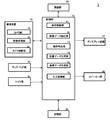
まず、本発明の第一実施形態である眼鏡型端末について説明する。図1(a)は本発明の第一実施形態である眼鏡型端末の概略平面図、同図(b)はその眼鏡型端末の概略右側面図、図2は第一実施形態の眼鏡型端末の概略斜視図、図3は第一実施形態の眼鏡型端末の概略ブロック図である。
[First embodiment]
First, the spectacles type terminal which is 1st embodiment of this invention is demonstrated. FIG. 1A is a schematic plan view of a glasses-type terminal according to the first embodiment of the present invention, FIG. 1B is a schematic right side view of the glasses-type terminal, and FIG. 2 is a glasses-type terminal according to the first embodiment. FIG. 3 is a schematic block diagram of the eyeglass-type terminal of the first embodiment.
第一実施形態の眼鏡型端末は、ユーザ(使用者)が眼鏡のように装着して使用する、例えばグーグル社のグーグルグラスである。この眼鏡型端末1は、図1から図3に示すように、レンズ部を備える眼鏡本体部(眼鏡)10と、眼鏡本体部10に設けられたディスプレイ装置(表示装置)20と、ユーザの前方を撮像するための撮像装置30と、タッチパッド部40と、マイク部50と、スピーカ部60と、制御部70と、通信部80と、記憶部90とを備える。
The eyeglass-type terminal of the first embodiment is, for example, Google Glass of Google Inc., which a user (user) wears like glasses. As shown in FIGS. 1 to 3, the spectacle-
眼鏡本体部10は、図2に示すように、二つのレンズ部11,11を有する一般的な眼鏡である。レンズ部11に取り付けるレンズは、視力を矯正するための凸レンズや凹レンズであってもよいし、視力矯正機能を持たないただのガラスやプラスチック等であってもよい。また、眼鏡本体部10は、レンズ部11に取り付けるレンズを省略したものであってもよい。
As shown in FIG. 2, the spectacle
ディスプレイ装置20は、透過型のプリズムディスプレイである。具体的に、ディスプレイ装置20は、例えば液晶パネル(表示デバイス)を有する小型プロジェクタと、光学系と、ハーフミラーとを備える。ここで、ハーフミラーは、図1及び図2に示すように、眼鏡本体部10における右眼用のレンズ部11の前に配置されたプリズムの中に埋め込まれている。液晶パネルに表示された画像や映像は、光学系を介してハーフミラーに投影される。実際、このディスプレイ装置20(ハーフミラー)には極小な画面が表示される。ユーザは、眼鏡型端末1を使用すると、ディスプレイ装置20(ハーフミラー)に表示される極小な画面の像である半透明の画面を空中に浮かんでいるように見ることができる。この浮かんで見える半透明の画面は、ユーザにとっては、8フィート離れて視る25インチの画面に相当するものである。第一実施形態では、この浮かんで見える画面が半透明である場合について説明するが、一般に、この画面は半透明でなくてもよい。また、第一実施形態では、この浮かんで見える画面が、図1及び図2に示すようにユーザの視野の右上の位置に表示される場合について説明するが、一般に、この画面は、ユーザの視野の中央や左上や右下等の位置に表示するようにしてもよい。なお、以下では、このディスプレイ装置20(ハーフミラー)に表示される極小の画面のことを「元画面」、眼鏡型端末1を使用するユーザに空中に浮かんでいるように見える画面のことを「視認画面」とも称する。
The
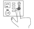
具体的に、ディスプレイ装置20には、文字入力画面等の各種の画面が表示される。図4は文字入力画面の一例を示す図である。図4に示すように、文字入力画面200は、キーボード画像210と、入力した文字等を表示するための表示領域220とを有する。キーボード画像210には、各文字(記号を含む)と対応付けられた複数の文字キー画像と、特定の機能が付与された複数の機能キー画像とが設けられている。図4の例では、キーボード画像210における文字キー画像の配列として、QWERTY配列を採用している。なお、キーボード画像210は、ひらがな50音配列のキーボード画像、各国の言語のキーボード画像、テンキー画像、或いは携帯電話のキー配列と同様のキー画像等であってもよい。また、表示領域220には、例えば検索画面が表示される。図5は文字入力画面200に表示される検索画面の一例を示す図である。この検索画面221は、インターネットのサイトを検索するためのものであり、キーワード入力部2211と、検索結果を表示する検索結果表示部2212とを有する。ユーザは、文字入力画面200を視認画面Sとして見ているときに、そのキーボード画像210のキー画像を利用して、キーワード入力部2211にキーワードを入力することができる。
Specifically, various screens such as a character input screen are displayed on the
第一実施形態では、ユーザは視認画面Sに対して指でタッチ操作を行うことにより、各種の指示を制御部70に与えることができる。そして、制御部70は、その指示の内容を認識し、その認識した指示の内容に応じて、ディスプレイ装置20に表示する元画面Mの制御を行うことになる。ここで、第一実施形態では、タッチ操作とは、通常のタッチパネルに対して行われるタッチ操作と同様に、タップ操作、ダブルタップ操作、長押し操作(ロングタップ)、ドラッグ操作、フリック操作、ピンチイン操作、ピンチアウト操作等の各種の操作をいうものとする。
In the first embodiment, the user can give various instructions to the
撮像装置30は、図1及び図2に示すように、ディスプレイ装置20に隣接する眼鏡本体部10の柄の部分に設けられている。この撮像装置30は、図3に示すように、カメラ部31と、画像処理部32と、カメラ制御部33とを備える。カメラ部31はレンズや撮像素子を有するものである。画像処理部32は、カメラ部31で撮像して得られた画像データに基づいてその撮像した画像の色や階調の補正処理を行ったり、画像データの圧縮等の画像処理を行ったりするものである。カメラ制御部33は、画像処理部32を制御したり、制御部70との間で画像データのやり取りを制御したりする。なお、本実施形態では、画像処理部32は撮像装置30に設けられている場合について説明するが、この画像処理部32は、撮像装置30ではなく、制御部70に設けるようにしてもよい。
As shown in FIGS. 1 and 2, the
また、撮像装置30は、この撮像装置30が撮像することができる範囲である撮像範囲として、ユーザの視野の一部(或いは略全視野)を撮像することができる。特に、第一実施形態では、撮像装置30は、ユーザが認識する視認画面Sの位置、具体的には、例えば、ユーザが手で視認画面Sに触ろうとして手を伸ばすときの手の指の位置であって当該撮像装置30から奥行き方向に沿って略一定の距離だけ離れた位置にある被写体にピントが合うように構成されている。しかも、そのピントが合う範囲(被写界深度)は狭い範囲に制限されている。例えば、ピントが合う位置は撮像装置30から約40cm離れた位置に設定されており、その被写界深度は約5cmの範囲である。但し、第一実施形態では、撮像装置30がこのようにピントの合う範囲を狭い範囲に制限するのは、基準データの設定、文字入力、及び画面表示のための操作を行う場合に限られる。通常のカメラ撮影を行う場合やその他の状況にある場合には、ピントの合う範囲は狭い範囲に制限されない。なお、撮像装置30としては、例えば、通常のカメラと同じように距離リング(ピントリング)を用いて手動で設定を変更することにより、ピントが合う位置を切り替えることができるものを用いるようにしてもよい。
Moreover, the
また、第一実施形態では、撮像装置30におけるピントが合う位置を、ユーザが認識する視認画面Sの位置に設定している。このため、ユーザが視認画面Sに対して指で操作を行っている場合、撮像装置30は、その操作を行っている指をピントが合った状態で撮像することになる。撮像装置30で撮像して得られた画像データは制御部70に送られ、制御部70により記憶部90に記憶される。また、第一実施形態の撮像装置30は、静止画像の撮影機能と動画像の撮影機能とを備えており、制御部70は必要に応じて画像データとして静止画像データを取得したり、動画像データを取得したりすることができる。
In the first embodiment, the in-focus position in the
眼鏡本体部10の柄の部分には、図3に示すように、タッチパッド部40、マイク部50、骨伝導型のスピーカ部60、各種のセンサ部、及びバッテリー部等が設けられている。なお、図1及び図2では、図を簡略化するため、これら各部は省略している。タッチパッド部40は、ユーザがタッチ操作を行うことにより、制御部70に各種の指示を与えるものである。マイク部50は、眼鏡本体部10を音声による指示で操作するために、ユーザの音声を入力するものである。マイク部50から入力された音声情報は、制御部70に送られ、制御部70がその音声情報を解析することになる。また、スピーカ部60は、骨の振動を利用してユーザに音声情報を伝えるものである。一般に、スピーカ部60としては、骨の振動を利用してユーザに音声情報を伝えるものに限らず、通常のスピーカ、イヤホン、ヘッドホン等を用いるようにしてもよい。なお、各種のセンサ部及びバッテリー部等は本願発明とは直接関係がないので、本実施形態ではこれらについての詳細な説明は省略する。
As shown in FIG. 3, a
制御部70は、中央演算処理装置(CPU)等を備えており、眼鏡型端末1の全般を制御する。例えば、制御部70は、元画面Mをディスプレイ装置20に表示するのを制御したり、撮像装置30による撮像を制御したりする。また、制御部70は、タッチパッド部40が操作されたときに、その操作により指示された内容を認識し、その認識した内容に応じた処理を実行したり、マイク部50から音声が入力されたときに、その入力された音声情報の内容を認識し、その認識した内容に応じた処理を実行したりする。更に、制御部70は、スピーカ部60により発する音声情報を制御する。具体的に、この制御部70は、図3に示すように、表示制御部71と、画像データ抽出部72と、操作判定部73と、位置データ生成部74と、基準データ生成部75と、入力制御部76とを備える。
The
表示制御部71は、ユーザがマイク部50による音声指示、或いはタッチパッド部40の操作による指示を行ったときに、その指示の内容に応じて、ディスプレイ装置20に表示すべき元画面Mの内容を選択し、その選択した元画面Mの表示を制御する。これにより、ディスプレイ装置20にはユーザの指示した元画面Mが表示され、ユーザはその元画面Mに対応する視認画面Sを見ることができる。
When the user gives a voice instruction from the
画像データ抽出部72は、ユーザが視認画面Sに対して指で操作を行った際に撮像装置30でピントが合った被写体が撮像されたときに、その撮像して得られた画像データに基づいて当該被写体が指であるかどうかを判断して、指が存在している画像データを抽出するものである。被写体が指であるかどうかを判断するには、一般の画像認識の方法が用いられる。第一実施形態では、撮像装置30の被写界深度を狭い範囲に制限しているので、被写体が指であると判断されれば、当該指は撮像装置30から奥行き方向に沿って略一定の距離だけ離れた位置にあると考えられる。このように、画像データ抽出部72では、当該指が撮像装置30から奥行き方向に沿って略一定の距離だけ離れた位置にある画像データが抽出される。また、操作判定部73、位置データ生成部74、基準データ生成部75では、画像データ抽出部72で抽出された画像データに基づいて処理が行われることになる。
The image
操作判定部73は、ユーザが視認画面Sに対して操作を行った指を撮像装置30が撮像したときに、その撮像して得られた画像データであって画像データ抽出部72で抽出されたものに基づいて当該指による操作がどのような内容の操作であるかを判定するものである。これにより、操作判定部73は、当該指による操作が、タップ操作、ダブルタップ操作、長押し操作等のうちいずれの操作であるかを認識することができる。その認識した当該指による操作の内容に関するデータは記憶部90に記憶される。
The
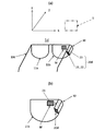
位置データ生成部74は、ユーザが視認画面Sに対して操作を行った指を撮像装置30が撮像したときに、その撮像して得られた画像データであって画像データ抽出部72で抽出されたものに基づいて撮像装置30の撮像範囲における当該指(指先)の位置データを生成するものである。ここで、本実施形態では、撮像装置30の撮像範囲内において、図2に示すように、左右方向をX軸方向、上下方向Y軸方向とするXY座標系が設定されている。このXY座標系の原点は、例えば撮像範囲における左下の点である。位置データ生成部74は、このXY座標系において指の位置データを取得する。なお、三次元的な位置データを得る必要がある場合には、このXY座標系において奥行き方向にZ軸方向をとり、これによりXYZ座標系を構成することにする。
The position
基準データ生成部75は、ユーザが視認画面Sにおける一又は複数の所定位置において指で操作を行ったときに、操作判定部73で各所定位置における操作が所定の操作であると判定された画像データに基づいて位置データ生成部74で生成された当該指の位置データを用いて、当該視認画面Sに関するデータを生成するものである。この生成された視認画面Sに関するデータは基準データとして記憶部90に記憶される。基準データとしては、視認画面Sの位置及び大きさを特定できるようなデータが用いられる。例えば、ユーザが視認画面Sの外枠の四隅に対して指で操作を行った場合には、四隅の各位置における指の位置データを基準データとして用いることができる。ここで、画像データ抽出部72が抽出した画像データは、撮像装置30からZ軸方向に沿って略一定の距離だけ離れた位置にある指を撮像したものであるので、この四隅の各位置における指の位置データは、撮像装置30からZ軸方向に沿って略一定の距離だけ離れた位置においてXY平面に平行な(略ユーザの身体と平行な)平面上での指の位置情報を表していると考えることができる。また、ユーザが視認画面Sの外枠の四隅のうち一箇所に対して指で操作を行った場合には、その一箇所における指の位置データと、当該視認画像Sに対応する元画像Mのデータから得られる視認画面Sの大きさ(例えば、予め算出又は測定した縦幅、横幅)に関するデータとを基準データとして用いることができる。
When the user performs an operation with a finger at one or more predetermined positions on the viewing screen S, the reference
入力制御部76は、ユーザが視認画面Sに対して指で操作を行ったときに、操作判定部73で判定して得られた当該指による操作の内容に関するデータ及び位置データ生成部74で生成された当該指の位置データと、記憶部90に記憶されている当該視認画面Sに関する基準データとに基づいて、当該指による操作に対応する入力指示の内容を認識し、その認識した入力指示の内容に応じて、ディスプレイ装置20に表示する元画面Mの制御を行う。例えば、視認画面Sが図4に示す文字入力画面200である場合、入力制御部76は、その視認画面Sに関する基準データに基づいて、撮像装置30の撮像範囲内でユーザが見ている当該文字入力画面200の存在する範囲を認識することができる。このとき、入力制御部76は、当該文字入力画面200の構成が予め分かっているので、当該文字入力画面200におけるキーボード画像210の範囲や、各文字キー画像の領域等も認識することができる。したがって、例えばユーザがキーボード画像210に対して指で文字キー画像のタッチ操作を行った場合、入力制御部76は、その指の位置データから得られる指の位置が、キーボード画像210におけるどの文字キー画像の領域に対応するのかを調べることにより、操作された文字キーを特定することができる。
When the user performs an operation with the finger on the viewing screen S, the
なお、入力制御部76は、ユーザが視認画面Sに対して指で操作を行った際に当該指による操作に対応する入力指示の内容を認識する場合、まず、記憶部90に記憶されている当該視認画面Sに関する基準データに基づいて、撮像装置30の撮像範囲に相当する仮想平面上に、当該視認画面Sに対応する画面である基準画面を生成し、次に、位置データ生成部74で生成された当該指の位置データが基準画面のどの位置に対応するのかを調べることにより、当該指で操作された視認画面S上の位置を特定するようにしてもよい。
Note that when the user performs an operation with the finger on the viewing screen S when the user recognizes the content of the input instruction corresponding to the operation with the finger, the
通信部80は、外部との間で情報の通信を行うものである。記憶部90には、各種のプログラムやデータ等が記憶されている。記憶部90に記憶されているプログラムには、例えば、基準データの設定処理を行うための基準データ設定処理用プログラムと、視認画面Sが文字入力画面200である場合にその文字入力画面200に対して行われた操作に基づいて文字入力の処理を行うための文字入力処理用プログラムと、視認画面Sに対して行われた操作に基づいて視認画面Sに対応する元画像Mの拡大・縮小や切替等の画面表示の処理を行うための画面表示処理用プログラムとが含まれている。また、記憶部90に記憶されているデータには、例えば、各種の元画面Mの画像データ、各元画面Mに関するデータ(具体的には、当該元画面Mの大きさ、形状、内容、構成等を示すデータ)や、後述する基準データ設定用の元画面を作成する際に用いる各種の画像データが含まれる。更に、この記憶部90は作業用のメモリとしても使用される。
The
第一実施形態の眼鏡型端末1では、ユーザが視認画面Sに対して指で操作を行ったときに、入力制御部76は、操作判定部73で判定して得られた当該指による操作の内容に関するデータ及び位置データ生成部74で生成された当該指の位置データと、記憶部90に記憶されている当該視認画面Sに対する基準データとに基づいて、当該指による操作に対応する入力指示の内容を認識し、その認識した入力指示の内容に応じて、ディスプレイ装置20に表示する元画面Mの制御を行う。このため、ユーザは、自己が見ている視認画面Sに対して、通常のタッチパネルに表示された画面に対して操作するのと同様の操作を行うことにより、当該操作に対応する指示を入力することができる。実際、ユーザが視認画面Sに対して指でタッチ操作を行うと、入力制御部76は、その視認画面Sがタッチパネルに表示されているときと同様に、当該タッチ操作に対応する指示を認識することができる。例えば、入力制御部76は、ユーザが視認画面Sに対して指でダブルタップ操作を行ったときに、その視認画面Sに対応する元画面Mを拡大又は縮小するという指示を認識し、ユーザが視認画面Sに対して指で長押し操作を行うと、元画面Mとしてオプションメニューの画面を表示するという指示を認識し、そして、ユーザが視認画面Sに対して指でドラッグ操作を行うと、元画面Mをスクロールして表示するという指示を認識する。また、ユーザが文字入力画面200における文字キー画像に対して指でタッチ操作を行えば、入力制御部76は、その文字入力画面200がタッチパネルに表示されているときと同様に、当該操作に対応する指示、すなわち当該文字キーの入力指示を認識し、元画面Mにその入力指示された文字を表示する処理を行う。
In the eyeglass-
なお、第一実施形態では、ユーザは、空中に浮いているように見える視認画面Sに対して指でタッチ操作を行うので、通常のタッチパネルに表示された画面に対してタッチ操作する場合には行うことのできない態様でタッチ操作を行うこともできる。図6及び図7は視認画面Sに対して行われるタッチ操作の態様を説明するための図である。通常、ユーザは、図6(a)に示すように、視認画面Sの正面側から一本の指でタッチ操作を行うが、図6(b)に示すように、視認画面Sの裏面側から一本の指でタッチ操作を行うことができる。また、ユーザは、図7(a)に示すように、視認画面Sの正面側から複数の指でタッチ操作を行ったり、図7(b)に示すように、視認画面Sの裏面側から複数の指でタッチ操作を行ったりすることができる。 In the first embodiment, the user performs a touch operation with the finger on the visual screen S that appears to float in the air. Therefore, when the user performs a touch operation on the screen displayed on the normal touch panel, Touch operations can also be performed in a manner that cannot be performed. 6 and 7 are diagrams for explaining a mode of a touch operation performed on the viewing screen S. FIG. Normally, the user performs a touch operation with one finger from the front side of the viewing screen S as shown in FIG. 6 (a), but from the back side of the viewing screen S as shown in FIG. 6 (b). Touch operation can be performed with one finger. Further, the user performs a touch operation with a plurality of fingers from the front side of the viewing screen S as shown in FIG. 7A, or a plurality of users from the back side of the viewing screen S as shown in FIG. You can touch with your finger.
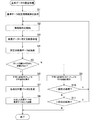
次に、第一実施形態の眼鏡型端末1において基準データを設定する処理について説明する。図8は第一実施形態の眼鏡型端末1において基準データの設定処理の手順を説明するためのフローチャートである。
Next, processing for setting reference data in the eyeglass-
ユーザは、マイク部50から音声で基準データの設定を行う旨を指示するか、或いはタッチパッド部40を用いた操作等により基準データの設定を行う旨を指示する。制御部70は、その指示を受けると、基準データ設定処理用プログラムを記憶部90から読み出し、図8に示す処理フローにしたがって基準データの設定処理を行う。
The user instructs to set the reference data by voice from the
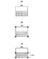
まず、表示制御部71は、現在、ディスプレイ装置20に表示されている元画面Mにおける一又は複数の所定位置に例えば円の画像を追加することにより、新たな元画面M(基準データ設定用の元画面)を作成して、ディスプレイ装置20に表示する(S1)。ここで、円の画像は、ユーザがその円の位置に対して指で操作を行うべきことを示す目印である。図9は基準データを設定する処理の際に表示される元画面Mの例を示す図である。この例では、元画面Mが文字入力画面200である場合を示している。当初は、図9(a)に示す通常の文字入力画面200がディスプレイ装置20に表示されているが、ステップS1の処理が実行されると、図9(b)に示す文字入力画面201(基準データ設定用の元画面)がディスプレイ装置20に表示されることになる。この図9(b)に示す文字入力画面201では、その四隅の位置に、円と数字とを示す画像が追加されている。図9(b)に示す文字入力画面201がディスプレイ装置20に表示されると、ユーザはその文字入力画面201に対応する視認画面S(基準データ設定用の視認画面)、すなわち図9(b)に示す文字入力画面201と同じ内容の画面を見ることになる。なお、図9(b)では、文字入力画面201の四隅に円の画像を表示しているが、図9(c)に示すように、文字入力画面201のキーボード画像210の四隅に円の画像を表示するようにしてもよい。
First, the
ステップS1の処理後、制御部70は、撮像装置30の撮像動作を開始する(S2)。ユーザは、基準データ設定用の視認画面Sとして図9(b)に示す文字入力画面201を見ると、この基準データ設定用の視認画面Sにおいて、数字が付された各円に対して数字の順番に指で所定の操作、例えばタップ操作を行う。ここで、ユーザが所定の操作を行うのは、制御部70に対してユーザが操作している位置を知らせるためである。かかるユーザによる操作は撮像装置30で撮像される。このとき、本実施形態では、撮像装置30はピントが合った被写体を撮像する。そして、画像処理部32がその撮像して得られた画像データに対して所定の画像処理を施し、その画像処理を施した画像データが制御部70に送られる(S3)。
After the process of step S1, the
次に、画像データ抽出部72は、撮像装置30で撮像して得られた画像データに基づいて、被写体が指であるかどうかを判断し、指が存在している画像データを抽出する(S4)。ここで、撮像装置30は、ピントが合った被写体を撮像して得られた画像データを画像データ抽出部72に送っている。このため、画像データ抽出部72は、当該指が撮像装置30からZ軸方向に沿って略一定の距離だけ離れた位置にある画像データを抽出することになる。その後、操作判定部73は、画像データ抽出部72で抽出された画像データに基づいて当該指による操作が所定の操作(ここでは、タップ操作)であるかどうかを判定する。操作判定部73は、このような判定処理を行い、四つの円の全てに対する指によるタップ操作が正常に認識されたかどうかを判断する(S5)。例えば、予め定めた所定の時間内に指による操作がタップ操作であるという判定が一回、二回又は三回しかなされなかった場合や、予め定めた所定の時間内に画像データ抽出部72から指が存在している画像データが送られてこなかった場合等には、操作判定部73は、四つの円の全てに対する指によるタップ操作が正常に認識されなかったと判断する。操作判定部73は、四つの円の全てに対する指によるタップ操作が正常に認識されたと判断すると、当該指による操作の内容に関するデータを記憶部90に記憶すると共に、指によるタップ操作が正常に認識された旨の信号を表示制御部71に送る。そして、表示制御部71は、指によるタップ操作が正常に認識されたことを意味する緑色ランプを示す画像を元画面Mに追加して、ディスプレイ装置20に表示する(S6)。なお、このとき、表示制御部71は、緑色ランプを示す画像とともに、或いはその画像に代えて、指によるタップ操作が正常に認識されたことを意味する文字や図形を示す画像を元画面Mに追加するようにしてもよい。或いは、制御部70は、指によるタップ操作が正常に認識されたことを意味する画像の表示とともに、若しくは当該画像の表示に代えて、特定の報知音をスピーカ部60から発するようにしてもよい。
Next, the image
ステップS6の処理の後、位置データ生成部74は、操作判定部73で各円における操作が所定の操作であると判定された画像データに基づいて、撮像装置30の撮像範囲における各指(指先)の位置データ(XY座標)を生成する(S7)。そして、基準データ生成部75は、こうして生成された四つの位置データを、現在表示されている視認画面Sに関する基準データとして記憶部90に記憶する(S8)。かかる基準データは当該視認画面Sの位置及び大きさを特定するものであるので、制御部70は、この基準データを用いると、撮像装置30の撮像範囲内でユーザが見ている当該視認画面Sの存在する範囲を認識することができるようになる。ステップS8の処理がなされると、基準データの設定処理が終了する。
After the process of step S6, the position
一方、ステップS5の処理において、操作判定部73は、四つの円の全てに対する指によるタップ操作が正常に認識されていないと判断すると、その旨の信号を表示制御部71に送る。そして、表示制御部71は、指によるタップ操作が正常に認識されなかったことを意味する赤色ランプを示す画像を元画面Mに追加して、ディスプレイ装置20に表示する(S9)。ユーザは、この赤色ランプを示す画像を見ると、再度、基準データ設定用の視認画面Sにおいて各円に対して指でタップ操作を行わなければならない。なお、このとき、表示制御部71は、赤色ランプを示す画像とともに、或いはその画像に代えて、指によるタップ操作が正常に認識されなかったことを意味する文字や図形を示す画像を元画面Mに追加するようにしてもよい。或いは、制御部70は、指によるタップ操作が正常に認識されなかったことを意味する画像の表示とともに、若しくは当該画像の表示に代えて、特定の報知音をスピーカ部60から発するようにしてもよい。
On the other hand, in the process of step S5, when the
ステップS9の処理後、制御部70は、今回のステップS5の処理が一回目の処理であるかどうかを判断する(S10)。今回のステップS5の処理が一回目の処理であれば、ステップS2に移行する。これに対し、今回のステップS5の処理が一回目の処理でなければ、制御部70は、今回のステップS5の処理が二回目の処理であるかどうかを判断する(S11)。今回のステップS5の処理が二回目の処理であれば、ステップS2に移行し、一方、今回のステップS5の処理が二回目の処理でなければ、基準データの設定処理を終了する。すなわち、視認画面S中に赤色ランプが表示された場合、ユーザには、指による操作を行う機会がさらに二回与えられる。なお、それでも指による操作が正常に認識されなかった場合には、再度、基準データの設定処理を実行すればよい。
After the process of step S9, the
なお、第一実施形態では、上記のステップS5において、操作判定部73が、各円に対する指による操作がタップ操作であるかどうかを判定し、四つの円の全てに対する指によるタップ操作が正常に認識されたかどうかを判断する場合について説明したが、操作判定部73は、各円に対する指による操作が行われる度に、その操作がタップ操作であるかどうかを判定すると共にそのタップ操作が正常に認識されたかどうかを判断するようにしてもよい。この場合、表示制御部71は、各円に対する指によるタップ操作が正常に認識されたと操作判定部73が判断する度に、当該円に対するタップ操作が正常に認識されたことを意味する画像を元画面Mに表示し、一方、各円に対する指によるタップ操作が正常に認識されなかったと操作判定部73が判断する度に、当該円に対するタップ操作が正常に認識されなかったことを意味する画像を元画面Mに表示することが望ましい。具体的に、各円に対するタップ操作が正常に認識されたことを意味する画像としては、例えば、当該円を反転表示した画像や、当該円の色を緑色で表示した画像等を挙げることができ、各円に対するタップ操作が正常に認識されなかったことを意味する画像としては、例えば、当該円の色を赤色で表示した画像等を挙げることができる。また、制御部70は、各円に対するタップ操作が正常に認識されたことを意味する画像若しくは各円対するタップ操作が正常に認識されなかったことを意味する画像の表示とともに、若しくは当該画像の表示に代えて、特定の報知音をスピーカ部60から発するようにしてもよい。
In the first embodiment, in step S5 described above, the
また、第一実施形態では、ユーザが視認画面Sにおける所定の四箇所に対して指で所定の操作を行い、四つの位置データを取得する場合について説明したが、ユーザが視認画面Sにおける所定の一箇所、二箇所又は三箇所に対して指で所定の操作を行うことにより、それらの位置データを取得するようにしてもよい。但し、この場合、視認画面Sの大きさに関するデータを、その視認画面Sに対応する元画面Mのデータ等から演算により予め算出して、記憶部90に記憶しておく必要がある。そして、その取得した各位置データと視認画面Sの大きさに関するデータとが、基準データを構成することになる。
Moreover, although 1st embodiment demonstrated the case where a user performs predetermined operation with a finger | toe with respect to the predetermined four places in the visual recognition screen S, and acquires four position data, You may make it acquire those positional data by performing predetermined operation with a finger | toe with respect to one place, two places, or three places. However, in this case, the data related to the size of the viewing screen S needs to be calculated in advance from the data of the original screen M corresponding to the viewing screen S and stored in the
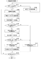
次に、第一実施形態の眼鏡型端末1における文字入力の処理について説明する。図10は第一実施形態の眼鏡型端末1における文字入力の処理の手順を説明するためのフローチャートである。ここでは、予めディスプレイ装置20に元画面Mとして文字入力画面200が表示されているものとする。
Next, the character input process in the glasses-
ユーザは、マイク部50から音声で文字入力を行う旨を指示するか、或いはタッチパッド部40を用いた操作等により文字入力を行う旨を指示する。制御部70は、その指示を受けると、文字入力処理用プログラムを記憶部90から読み出し、図10に示す処理フローにしたがって文字入力の処理を行う。なお、この文字入力の処理は、元画面Mとして文字入力画面200がディスプレイ装置20に表示されたときに自動的に実行されるようにしてもよい。
The user instructs to input characters by voice from the
まず、制御部70は、現在、ディスプレイ装置20に表示されている元画面Mに対応する視認画面Sに関する基準データが記憶部90に記憶されているかどうかを判断する(S21)。視認画面Sに関する基準データが記憶部90に記憶されていなければ、制御部70は、基準データ設定処理用プログラムを記憶部90から読み出し、図8に示す処理フローにしたがって基準データの設定処理を行う(S22)。その後、ステップS21に移行する。なお、本実施形態では、視認画面Sに関する基準データが記憶部90に記憶されていない場合に基準データの設定処理を実行することにしているが、視認画面Sに関する基準データが記憶部90に記憶されている場合でも、ユーザから指示を受けたときに、基準データの設定処理を実行して、再度、基準データを生成するようにしてもよい。
First, the
一方、ステップS21の処理において視認画面Sに関する基準データが記憶部90に記憶されていると判断されると、制御部70は、撮像装置30の撮像動作を開始する(S23)。ユーザは、視認画面Sである文字入力画面200のキーボード画像210に対して指で所定の操作、例えばタップ操作を行う。ここで、ユーザが所定の操作を行うのは、制御部70に対してユーザが操作している位置を知らせるためである。かかるユーザによる操作は撮像装置30で撮像され、その得られた画像データが画像処理部32に送られる。そして、画像処理部32が画像データに対して所定の画像処理を施し、その画像処理を施した画像データが制御部70に送られる(S24)。
On the other hand, when it is determined that the reference data regarding the viewing screen S is stored in the
次に、画像データ抽出部72は、撮像装置30で撮像して得られた画像データに基づいて、被写体が指であるかどうかを判断し、指が存在している画像データを抽出する(S25)。すなわち、画像データ抽出部72は、当該指が撮像装置30からZ軸方向に沿って略一定の距離だけ離れた位置にある画像データを抽出する。次に、操作判定部73は、画像データ抽出部72で抽出された画像データに基づいて当該指による操作が所定の操作(ここでは、タップ操作)であるかどうかを判定する。この判定は予め定めた所定の時間内に行われる。そして、操作判定部73は、当該指による操作がタップ操作であれば、文字入力のための操作が正常に認識されたと判断し、一方、当該指による操作がタップ操作でなければ、文字入力のための操作が正常に認識されなかったと判断する(S26)。操作判定部73は、文字入力のための操作が正常に認識されたと判断すると、当該指による操作の内容に関するデータを記憶部90に記憶すると共に、文字入力のための操作が正常に認識された旨の信号を表示制御部71に送る。表示制御部71は、その信号を受けると、文字入力のための操作が正常に認識されたことを意味する緑色ランプを示す画像を元画面Mに追加して、ディスプレイ装置20に表示する(S28)。なお、表示制御部71は、緑色ランプを示す画像とともに、或いはその画像に代えて、文字入力のための操作が正常に認識されたことを意味する文字や図形を示す画像を元画面Mに追加するようにしてもよい。或いは、上述したように、制御部70は、文字入力のための操作が正常に認識されたことを意味する画像の表示とともに、若しくは当該画像の表示に代えて、特定の報知音をスピーカ部60から発するようにしてもよい。
Next, the image
一方、操作判定部73は、ステップS26の処理において、予め定めた所定の時間内に文字入力のための操作が正常に認識されなかったと判断すると、その旨の信号を表示制御部71に送る。このとき例えば、予め定めた所定の時間内に画像データ抽出部72から指が存在している画像データが送られてこなかった場合にも、操作判定部73は、タップ操作が正常に認識されなかったと判断する。表示制御部71は、その信号を受けると、文字入力のための操作が正常に認識されなかったことを意味する赤色ランプを示す画像を元画面Mに追加して、ディスプレイ装置20に表示する(S27)。その後は、ステップS32に移行する。なお、このとき、表示制御部71は、赤色ランプを示す画像とともに、或いはその画像に代えて、文字入力のための操作が正常に認識されなかったことを意味する文字や図形を示す画像を元画面Mに追加するようにしてもよい。或いは、上述したように、制御部70は、文字入力のための操作が正常に認識されなかったことを意味する画像の表示とともに、若しくは当該画像の表示に代えて、特定の報知音をスピーカ部60から発するようにしてもよい。
On the other hand, when the
ステップS28の処理の後、位置データ生成部74は、操作判定部73で指による操作がタップ操作であると判定された画像データに基づいて、撮像装置30の撮像範囲における当該指(指先)の位置データを生成する(S29)。こうして生成された指の位置データは記憶部90に記憶される。
After the process of step S28, the position
次に、入力制御部76は、操作判定部73で判定して得られた当該指による操作の内容に関するデータ及び位置データ生成部74で生成された当該指の位置データと、記憶部90に記憶されている当該視認画面Sに関する基準データとに基づいて、当該指による操作に対応する入力指示の内容を認識する(S30)。例えば、ユーザがキーボード画像210における文字キー画像に対して指でタップ操作を行った場合には、入力制御部76は、その指の位置データから得られる指の位置が、キーボード画像210におけるどの文字キー画像の領域に対応するのかを調べることにより、今回のタップ操作が行われた文字キーを特定し、その特定した文字キーの入力が指示されたことを認識することができる。その後、入力制御部76は、認識した入力指示の内容に関する信号を表示制御部71に送り、表示制御部71はその入力指示の内容に応じた元画面Mをディスプレイ装置20に表示する(S31)。
Next, the
ステップS31又はステップS27の処理の後、制御部70は、ユーザから文字入力を終了する旨の指示を受けたかどうかを判断する(S32)。文字入力を終了する旨の指示を受けていれば、文字入力の処理が終了する。これに対し、文字入力を終了する旨の指示を受けていなければ、ステップS23に移行し、文字入力の処理を継続する。なお、ユーザは、文字入力を終了する旨の指示を、例えば音声やタッチパッド部40のタッチ操作により行う。
After the process of step S31 or step S27, the
次に、第一実施形態の眼鏡型端末1における画面表示の処理について説明する。図11は第一実施形態の眼鏡型端末1における画面表示の処理の手順を説明するためのフローチャートである。
Next, screen display processing in the eyeglass-
ユーザは、マイク部50から音声で画面表示のための操作を行う旨を指示するか、或いはタッチパッド部40を用いた操作等により画面表示のための操作を行う旨を指示する。制御部70は、その指示を受けると、画面表示処理用プログラムを記憶部90から読み出し、図11に示す処理フローにしたがって画面表示の処理を行う。なお、この画面表示の処理は、元画面Mがディスプレイ装置20に表示されたときに自動的に実行されるようにしてもよい。
The user instructs the
まず、制御部70は、現在、ディスプレイ装置20に表示されている元画面Mに対応する視認画面Sに関する基準データが記憶部90に記憶されているかどうかを判断する(S41)。視認画面Sに関する基準データが記憶部90に記憶されていなければ、制御部70は、基準データ設定処理用プログラムを記憶部90から読み出し、図8に示す処理フローにしたがって基準データの設定処理を行う(S42)。その後、ステップS41に移行する。なお、本実施形態では、視認画面Sに関する基準データが記憶部90に記憶されていない場合に基準データの設定処理を実行することにしているが、視認画面Sに関する基準データが記憶部90に記憶されている場合でも、ユーザから指示を受けたときに、基準データの設定処理を実行して、再度、基準データを生成するようにしてもよい。
First, the
一方、ステップS41の処理において視認画面Sに関する基準データが記憶部90に記憶されていると判断されると、制御部70は、撮像装置30の撮像動作を開始する(S43)。ユーザは、視認画面Sに対して指で所望の操作を行う。かかるユーザによる操作は撮像装置30で撮像され、その得られた画像データが画像処理部32に送られる。そして、画像処理部32が画像データに対して所定の画像処理を施し、その画像処理を施した画像データが制御部70に送られる(S44)。
On the other hand, when it is determined in the process of step S41 that the reference data regarding the viewing screen S is stored in the
次に、画像データ抽出部72は、撮像装置30で撮像して得られた画像データに基づいて、被写体が指であるかどうかを判断し、指が存在している画像データを抽出する(S45)。すなわち、画像データ抽出部72は、当該指が撮像装置30からZ軸方向に沿って略一定の距離だけ離れた位置にある画像データを抽出する。次に、操作判定部73は、画像データ抽出部72で抽出された画像データに基づいて当該指による操作の内容を判定する。そして、操作判定部73は、当該指による操作が正常に認識されたかどうかを判断する(S46)。操作判定部73は、当該指による操作が正常に認識されたと判断すると、当該指による操作の内容に関するデータを記憶部90に記憶すると共に、当該指による操作が正常に認識された旨の信号を表示制御部71に送る。表示制御部71は、その信号を受けると、指による操作が正常に認識されたことを意味する緑色ランプを示す画像を元画面Mに追加して、ディスプレイ装置20に表示する(S48)。なお、表示制御部71は、緑色ランプを示す画像とともに、或いはその画像に代えて、指による操作が正常に認識されたことを意味する文字や図形を示す画像を元画面Mに追加するようにしてもよい。或いは、上述したように、制御部70は、指による操作が正常に認識されたことを意味する画像の表示とともに、若しくは当該画像の表示に代えて、特定の報知音をスピーカ部60から発するようにしてもよい。
Next, the image
一方、操作判定部73は、ステップS46の処理において、指による操作が正常に認識されなかったと判断すると、その旨の信号を表示制御部71に送る。このとき例えば、予め定めた所定の時間内に画像データ抽出部72から指が存在している画像データが送られてこなかった場合にも、操作判定部73は、タップ操作が正常に認識されなかったと判断する。表示制御部71は、その信号を受けると、指による操作が正常に認識されなかったことを意味する赤色ランプを示す画像を元画面Mに追加して、ディスプレイ装置20に表示する(S47)。その後は、ステップS52に移行する。なお、このとき、表示制御部71は、赤色ランプを示す画像とともに、或いはその画像に代えて、指による操作が正常に認識されなかったことを意味する文字や図形を示す画像を元画面Mに追加するようにしてもよい。或いは、上述したように、制御部70は、指による操作が正常に認識されなかったことを意味する画像の表示とともに、若しくは当該画像の表示に代えて、特定の報知音をスピーカ部60から発するようにしてもよい。
On the other hand, when the
ステップS48の処理の後、位置データ生成部74は、操作判定部73で指による操作の内容が判定された画像データに基づいて、撮像装置30の撮像範囲における当該指(指先)の位置データを生成する(S49)。こうして生成された指の位置データは記憶部90に記憶される。
After the process of step S48, the position
次に、入力制御部76は、操作判定部73で判定して得られた当該指による操作の内容に関するデータ及び位置データ生成部74で生成された当該指の位置データと、記憶部90に記憶されている当該視認画面Sに関する基準データとに基づいて、当該指による操作に対応する指示の内容を認識する(S50)。例えば、ユーザが視認画面Sに対して指でダブルタップ操作を行った場合には、入力制御部76は、今回の操作がダブルタップ操作であることを特定し、元画面Mを拡大(又は縮小)する旨の指示を受けたことを認識する。その後、入力制御部76は、認識した指示の内容に関する信号を表示制御部71に送り、表示制御部71はその指示の内容に応じた元画面Mをディスプレイ装置20に表示する(S51)。
Next, the
ステップS51又はステップS47の処理の後、制御部70は、ユーザから画面表示のための操作を終了する旨の指示を受けたかどうかを判断する(S52)。画面表示のための操作を終了する旨の指示を受けていれば、画面表示の処理が終了する。これに対し、画面表示のための操作を終了する旨の指示を受けていなければ、ステップS43に移行し、画面表示の処理を継続する。なお、ユーザは、画面表示のための操作を終了する旨の指示を、例えば音声やタッチパッド部40のタッチ操作により行う。
After the process of step S51 or step S47, the
第一実施形態の眼鏡型端末では、入力制御部が、ユーザが視認画面に対して指で操作を行ったときに、操作判定部で判定して得られた当該指による操作の内容に関するデータ及び位置データ生成部で生成された当該指の位置データと、記憶部に記憶されている当該視認画面に関する基準データとに基づいて、当該指による操作に対応する入力指示の内容を認識し、その認識した入力指示の内容に応じて、ディスプレイ装置に表示する元画面の制御を行う。このため、ユーザは、空中に浮かんでいるように見える視認画面に対して、通常のタッチパネルに表示された画面に対して操作するのと同様の操作を行うことにより、当該操作に対応する指示を入力することができる。したがって、第一実施形態の眼鏡型端末を用いると、ユーザは、通常のスマートフォン端末やタブレット端末と同様に、視認画面に対して操作を行うことにより、文字入力の操作や拡大・縮小等の各種の画面操作を容易且つ正確に行うことができる。 In the glasses-type terminal according to the first embodiment, the input control unit includes data related to the content of the operation with the finger obtained by the operation determination unit when the user performs an operation with the finger on the viewing screen, and Based on the position data of the finger generated by the position data generation unit and the reference data related to the viewing screen stored in the storage unit, the content of the input instruction corresponding to the operation by the finger is recognized and recognized. The original screen displayed on the display device is controlled according to the contents of the input instruction. For this reason, the user gives an instruction corresponding to the operation by performing the same operation as that performed on the screen displayed on the normal touch panel on the visual screen that seems to float in the air. Can be entered. Therefore, when using the eyeglass-type terminal of the first embodiment, the user can perform various operations such as character input operation and enlargement / reduction by operating the viewing screen in the same manner as a normal smartphone terminal or tablet terminal. The screen operation can be performed easily and accurately.
[第一実施形態の変形例]
次に、本発明の第一実施形態の変形例である眼鏡型端末について説明する。図21(a)は本発明の第一実施形態の変形例である眼鏡型端末の概略平面図、同図(b)はその眼鏡型端末の概略右側面図である。図22(a)はその眼鏡型端末の概略斜視図、同図(b)はディスプレイ装置に元画面を投影している様子を説明するための概略図である。尚、本変形例において、上述した第一実施形態のものと同一の機能を有するものには、同一の符号を付すことにより、その詳細な説明を省略する。
[Modification of First Embodiment]
Next, an eyeglass-type terminal that is a modification of the first embodiment of the present invention will be described. FIG. 21A is a schematic plan view of a glasses-type terminal which is a modification of the first embodiment of the present invention, and FIG. 21B is a schematic right side view of the glasses-type terminal. FIG. 22A is a schematic perspective view of the eyeglass-type terminal, and FIG. 22B is a schematic diagram for explaining a state in which the original screen is projected on the display device. In addition, in this modification, the thing which has the same function as the thing of 1st Embodiment mentioned above attaches | subjects the same code | symbol, and abbreviate | omits the detailed description.
第一実施形態の変形例である眼鏡型端末1dは、図21及び図22に示すように、レンズ部11a,11bを備える眼鏡本体部10dと、ディスプレイ装置20dと、撮像装置30と、タッチパッド部40と、マイク部50と、スピーカ部60と、制御部70と、通信部80と、記憶部90とを備える。
As shown in FIGS. 21 and 22, a spectacle-
この変形例の眼鏡型端末1dが第一実施形態の眼鏡型端末1と異なる点は、ディスプレイ装置20dの構成に関する点だけである。具体的に、ディスプレイ装置20dは、例えば液晶パネル(表示デバイス)を有する小型プロジェクタ21と、光学系22と、ハーフミラー23とを備える。これらの構成要素のうち、ハーフミラー23は、図21及び図22に示すように、眼鏡本体部10dにおける右側のレンズ部11bに埋め込まれている。液晶パネルに表示された元画面Mは、図22に示すように、光学系を介してハーフミラー23に投影される。
The spectacle-
本変形例の眼鏡型端末1dの作用・効果は上記第一実施形態のものと同様である。したがって、本変形例の眼鏡型端末1dを用いると、視野内に表示される視認画面に対して文字入力や、拡大・縮小等の各種の画面操作を容易且つ正確に行うことができる。
The operation and effect of the eyeglass-
[第二実施形態]
次に、本発明の第二実施形態である眼鏡型端末について説明する。図12は本発明の第二実施形態である眼鏡型端末の概略ブロック図である。尚、第二実施形態において、上述した第一実施形態のものと同一の機能を有するものには、同一の符号を付すことにより、その詳細な説明を省略する。
[Second Embodiment]
Next, the spectacles type terminal which is 2nd embodiment of this invention is demonstrated. FIG. 12 is a schematic block diagram of a glasses-type terminal according to the second embodiment of the present invention. In the second embodiment, those having the same functions as those in the first embodiment described above are denoted by the same reference numerals, and detailed description thereof is omitted.
第二実施形態の眼鏡型端末1aは、図12に示すように、レンズ部を備える眼鏡本体部10と、眼鏡本体部10に設けられたディスプレイ装置(表示装置)20と、ユーザの前方を撮像するための撮像装置30aと、タッチパッド部40と、マイク部50と、スピーカ部60と、制御部70aと、通信部80と、記憶部90とを備える。また、撮像装置30aは、カメラ部31と、画像処理部32と、カメラ制御部33aとを有し、制御部70aは、表示制御部71と、画像データ抽出部72aと、操作判定部73と、位置データ生成部74と、基準データ生成部75と、入力制御部76とを有する。
As shown in FIG. 12, the spectacle-
第二実施形態の眼鏡型端末1aが第一実施形態の眼鏡型端末と異なる点は、カメラ制御部33aがオートフォーカス制御部331を備えている点、及び、画像データ抽出部72aが、撮像装置30aから送られた画像データの中から、被写体が指であってその指が撮像装置30aからZ軸方向に沿って略一定の距離だけ離れた位置にある画像データを抽出する点である。
The eyeglass-
オートフォーカス制御部331は、撮像範囲内における所定の位置にある被写体に自動的にピントを合わせるようにカメラ部31を制御するものである。ここで、第二実施形態では、撮像装置30aは、撮像範囲内のどの位置においても、自動的にピントを合わせることができるように、多数のフォーカスポイントを有する。このため、ユーザが視認画面Sに対して指で操作を行っている場合、撮像装置30aは、その操作を行っている指に自動的にピントを合わせ、当該指をピントが合った状態で撮像することができる。また、オートフォーカス制御部331は、自動的にピントが合わせられた被写体を撮像したときに、その撮像した被写体までの距離データを算出する。この算出した距離データは当該画像データと関連付けられる。そして、撮像装置30aで撮像して得られた画像データとそれに関連付けられた距離データは制御部70aに送られる。なお、オートフォーカスの方式としては、被写体に赤外線・超音波などを照射し、その反射波が戻るまでの時間や照射角度により距離を検出するアクティブ方式、或いは、カメラ部31のレンズで捉えた画像を利用して測距を行う位相差検出方式やコントラスト検出方式等のパッシブ方式のいずれであってもよい。
The
また、画像データ抽出部72aは、ユーザが視認画面Sに対して指で操作を行った際に撮像装置30aでピントが合った被写体が撮像されたときに、その撮像して得られた画像データに基づいて当該被写体が指であるかどうかを判断し、且つ、その撮像して得られた画像データに関連付けられた距離データに基づいて当該被写体が撮像装置30aからZ軸方向に沿って予め定められた略一定の距離だけ離れているかどうかどうかを判断することにより、被写体が指であってその指が撮像装置30aからZ軸方向に沿って略一定の距離だけ離れている画像データを抽出するものである。被写体が指であるかどうかを判断するには、第一実施形態の場合と同様に一般の画像認識の方法が用いられる。また、被写体が撮像装置30aからZ軸方向に沿って略一定の距離だけ離れているかどうかを判断する際における略一定の距離というのは、撮像装置30aからユーザが認識する視認画面Sの位置までのZ軸方向の距離である。例えば、ユーザが視認画面Sを撮像装置30aから約40cm離れた位置に認識する場合、上記略一定の距離としては、撮像装置30aから約40cm±5cmの範囲内の距離に設定される。このように、画像データ抽出部72aは、視認画面Sが表示されている位置から極端に手前の位置や奥の位置で操作を行っている指の画像データを排除して、視認画面Sに対して適正な操作を行っている指の画像データを抽出することができる。なお、操作判定部73、位置データ生成部74、基準データ生成部75では、画像データ抽出部72aで抽出された画像データに基づいて処理が行われる。
The image
基準データ生成部75は、第一実施形態と同様に、ユーザが視認画面Sにおける一又は複数の所定位置において指で操作を行ったときに、操作判定部73で各所定位置における操作が所定の操作であると判定された画像データに基づいて位置データ生成部74で生成された当該指の位置データを用いて、当該視認画面Sに関するデータを基準データとして生成する。例えば、ユーザが視認画面Sの外枠の四隅に対して指で操作を行った場合には、四隅の各位置における指の位置データを基準データとして用いることができる。上述のように、第二実施形態でも、画像データ抽出部72aが抽出した画像データは、撮像装置30aからZ軸方向に沿って略一定の距離だけ離れた位置にある指を撮像したものであるので、この四隅の各位置における指の位置データは、撮像装置30aからZ軸方向に沿って略一定の距離だけ離れた位置においてXY平面に平行な(略ユーザの身体と平行な)平面上での指の位置情報を表していると考えることができる。
As in the first embodiment, the reference
次に、第二実施形態の眼鏡型端末1aにおいて基準データを設定する処理について説明する。
Next, processing for setting reference data in the eyeglass-
第二実施形態の眼鏡型端末1aにおける基準データの設定処理の手順を説明するためのフローチャートは、図8に示す第一実施形態のものと同様である。第二実施形態における基準データの設定処理が第一実施形態における基準データの設定処理と異なるのは、撮像装置30aでの処理(ステップS2、S3)と、画像データ抽出部72aによる画像データの抽出処理(ステップS4)とである。したがって、以下では、図8に示すフローチャートを用いて、第二実施形態における基準データの設定処理のうち第一実施形態における基準データの設定処理と異なる事項について説明する。
The flowchart for explaining the procedure of the reference data setting process in the eyeglass-
ステップS1の処理後、制御部70aは、撮像装置30aの撮像動作を開始する(S2)。ユーザは、基準データ設定用の視認画面Sとして図9(b)に示す文字入力画面201を見ると、この基準データ設定用の視認画面Sにおいて、数字が付された各円に対して数字の順番に指で所定の操作、例えばタップ操作を行う。かかるユーザによる操作は撮像装置30aで撮像される。このとき、オートフォーカス制御部331は、撮像範囲内にある被写体に自動的にピントを合わせるようにカメラ部31を制御し、撮像装置30aはピントが合った被写体を撮像する。また、オートフォーカス制御部331は、自動的にピントが合わせられた被写体を撮像したときに、その撮像した被写体までの距離データを算出し、この算出した距離データを当該画像データと関連付ける。この撮像して得られた画像データは画像処理部32に送られ、画像処理部32は画像データに対して所定の画像処理を施す。そして、その画像処理を施した画像データとそれに関連付けられた距離データとは制御部70aに送られる(S3)。
After the process of step S1, the
ステップS4では、画像データ抽出部72aは、まず、撮像装置30aで撮像して得られた画像データに基づいて被写体が指であるかどうかを判断することにより、指が存在している画像データを抽出する。その後、画像データ抽出部72aは、その抽出した指が存在している画像データに関連付けられた距離データに基づいて当該被写体が撮像装置30aからZ軸方向に沿って略一定の距離だけ離れているかどうかを判断することにより、被写体が指であってその指が撮像装置30aからZ軸方向に沿って略一定の距離だけ離れている画像データを抽出する。なお、第二実施形態の基準データの設定処理において、ステップS5以下の各処理の内容は第一実施形態のものと同様である。
In step S4, the image
次に、第二実施形態の眼鏡型端末1aにおける文字入力の処理について説明する。
Next, a character input process in the glasses-
第二実施形態の眼鏡型端末1aにおける文字入力の処理の手順を説明するためのフローチャートは、図10に示す第一実施形態のものと同様である。第二実施形態における文字入力の処理が第一実施形態における文字入力の処理と異なるのは、撮像装置30aでの処理(ステップS23、S24)と、画像データ抽出部による画像データの抽出処理(ステップS25)とである。したがって、以下では、図10に示すフローチャートを用いて、第二実施形態における文字入力の処理のうち第一実施形態における文字入力の処理と異なる事項について説明する。
The flowchart for explaining the procedure of the character input process in the glasses-
ステップS21の処理において視認画面Sに関する基準データが記憶部90に記憶されていると判断されると、制御部70aは、撮像装置30aの撮像動作を開始する(S23)。ユーザは、視認画面Sである文字入力画面200のキーボード画像210に対して指で所定の操作、例えばタップ操作を行う。かかるユーザによる操作は撮像装置30aで撮像される。このとき、オートフォーカス制御部331は、撮像範囲内にある被写体に自動的にピントを合わせるようにカメラ部31を制御し、撮像装置30aはピントが合った被写体を撮像する。また、オートフォーカス制御部331は、自動的にピントが合わせられた被写体を撮像したときに、その撮像した被写体までの距離データを算出し、この算出した距離データを当該画像データと関連付ける。この撮像して得られた画像データは画像処理部32に送られ、画像処理部32は画像データに対して所定の画像処理を施す。そして、その画像処理を施した画像データとそれに関連付けられた距離データとは制御部70aに送られる(S24)。
If it is determined in the process of step S21 that the reference data related to the viewing screen S is stored in the
ステップS25では、画像データ抽出部72aは、まず、撮像装置30aで撮像して得られた画像データに基づいて被写体が指であるかどうかを判断することにより、指が存在している画像データを抽出する。その後、画像データ抽出部72aは、その抽出した指が存在している画像データに関連付けられた距離データに基づいて当該被写体が撮像装置30aからZ軸方向に沿って略一定の距離だけ離れているかどうかを判断することにより、被写体が指であってその指が撮像装置30aからZ軸方向に沿って略一定の距離だけ離れている画像データを抽出する。なお、第二実施形態の文字入力の処理において、ステップS26以下の各処理の内容は第一実施形態のものと同様である。
In step S25, the image
次に、第二実施形態の眼鏡型端末1aにおける画面表示の処理について説明する。
Next, screen display processing in the eyeglass-
第二実施形態の眼鏡型端末1aにおける画面表示の処理の手順を説明するためのフローチャートは、図11に示す第一実施形態のものと同様である。第二実施形態における画面表示の処理が第一実施形態における画面表示の処理と異なるのは、撮像装置30aでの処理(ステップS43、S44)と、画像データ抽出部による画像データの抽出処理(ステップS45)とである。したがって、以下では、図11に示すフローチャートを用いて、第二実施形態における画面表示の処理のうち第一実施形態における画面表示の処理と異なる事項について説明する。
The flowchart for explaining the procedure of the screen display process in the glasses-
ステップS41の処理において視認画面Sに関する基準データが記憶部90に記憶されていると判断されると、制御部70aは、撮像装置30aの撮像動作を開始する(S43)。ユーザは、視認画面Sに対して指で所望の操作を行う。かかるユーザによる操作は撮像装置30で撮像される。このとき、オートフォーカス制御部331は、撮像範囲内にある被写体に自動的にピントを合わせるようにカメラ部31を制御し、撮像装置30aはピントが合った被写体を撮像する。また、オートフォーカス制御部331は、自動的にピントが合わせられた被写体を撮像したときに、その撮像した被写体までの距離データを算出し、この算出した距離データを当該画像データと関連付ける。この撮像して得られた画像データは画像処理部32に送られ、画像処理部32は画像データに対して所定の画像処理を施す。そして、その画像処理を施した画像データとそれに関連付けられた距離データとは制御部70aに送られる(S24)。
When it is determined in the process of step S41 that the reference data related to the viewing screen S is stored in the
ステップS45では、画像データ抽出部72aは、まず、撮像装置30aで撮像して得られた画像データに基づいて被写体が指であるかどうかを判断することにより、指が存在している画像データを抽出する。その後、画像データ抽出部72aは、その抽出した指が存在している画像データに関連付けられた距離データに基づいて当該被写体が撮像装置30aからZ軸方向に沿って略一定の距離だけ離れているかどうかを判断することにより、被写体が指であってその指が撮像装置30aからZ軸方向に沿って略一定の距離だけ離れている画像データを抽出する。なお、第二実施形態の画面表示の処理において、ステップS46以下の各処理の内容は第一実施形態のものと同様である。
In step S45, the image
第二実施形態の眼鏡型端末は、第一実施形態の眼鏡型端末と同様の作用・効果を奏する。特に、第二実施形態では、撮像装置が、被写体に自動的にピントを合わせることができるオートフォーカス制御部を有し、オートフォーカス制御部により自動的にピントが合わせられた被写体を撮像したときに、その撮像した被写体までの距離データを算出し、その算出した距離データを当該撮像して得られた画像データとともに出力することにより、より正確に被写体である指(指先)にピントを合わせて、その被写体を撮像することができるので、制御部は、その撮像して得られた画像データ及び距離データに基づいて、より正確に基準データを生成したり、文字入力の処理等を行ったりすることができる。 The eyeglass-type terminal of the second embodiment has the same operations and effects as the eyeglass-type terminal of the first embodiment. In particular, in the second embodiment, the imaging device has an autofocus control unit that can automatically focus on the subject, and when the subject is automatically focused by the autofocus control unit By calculating the distance data to the imaged subject and outputting the calculated distance data together with the image data obtained by the imaging, the finger (fingertip) that is the subject is more accurately focused, Since the subject can be imaged, the control unit can generate reference data more accurately based on the image data and distance data obtained by the imaging, or perform character input processing, etc. Can do.
尚、第二実施形態の眼鏡型端末においては、ディスプレイ装置として、第一実施形態の変形例におけるディスプレイ装置20dを用いるようにしてもよい。この場合、このディスプレイ装置20dは、図21及び図22に示すように、小型プロジェクタ21と、光学系22と、眼鏡本体部10dにおける右側のレンズ部11bに埋め込まれたハーフミラー23とを備える。
In the glasses-type terminal according to the second embodiment, the
[第二実施形態の第一変形例]
次に、本発明の第二実施形態の第一変形例である眼鏡型端末について説明する。図13は本発明の第二実施形態の第一変形例である眼鏡型端末の概略ブロック図である。尚、本変形例において、上述した第二実施形態のものと同一の機能を有するものには、同一の符号を付すことにより、その詳細な説明を省略する。
[First Modification of Second Embodiment]
Next, an eyeglass-type terminal that is a first modification of the second embodiment of the present invention will be described. FIG. 13 is a schematic block diagram of a glasses-type terminal that is a first modification of the second embodiment of the present invention. In addition, in this modification, what has the same function as the thing of 2nd embodiment mentioned above attaches | subjects the same code | symbol, and abbreviate | omits the detailed description.
第二実施形態の第一変形例である眼鏡型端末1bは、図13に示すように、眼鏡本体部10と、眼鏡本体部10に設けられたディスプレイ装置20と、ユーザの前方を撮像するための撮像装置30aと、タッチパッド部40と、マイク部50と、スピーカ部60と、制御部70bと、通信部80と、記憶部90とを備える。また、制御部70bは、表示制御部71と、画像データ抽出部72aと、操作判定部73と、位置データ生成部74bと、基準データ生成部75と、入力制御部76と、ずれ補正部77bとを有する。
As shown in FIG. 13, the eyeglass-
この第一変形例の眼鏡型端末1bが第二実施形態の眼鏡型端末1aと異なる主な点は、制御部70bがずれ補正部77bを備えている点である。また、本変形例では、記憶部90に記憶されている視認画面Sに関する基準データに基づいて得られる視認画面Sに対応する平面を「基準画面K」と称することにする。
The main difference between the eyeglass-
ユーザは、例えば文字入力を行う際に、実際に操作する画面(以下、「操作画面T」とも称する。)を、基準データに基づいて得られる基準画面Kより手前に位置していたり、奥に位置していたりするように認識して、その操作画面Tに対して指による操作を行うことがある。すなわち、操作画面Tと基準画面Kとの間にずれが生ずることがある。このずれが大きいと、制御部70bは、ユーザが指で操作したときに、その指の位置が基準画面K上でどの位置に対応するのかを正確に判断することができない可能性がある。ずれ補正部77bは、ユーザが操作画面Tに対して指で操作して得られた指の位置データを基準画面K上での位置データに換算する処理を行うものである。ここで、ユーザが操作画面Tに対して指で操作して得られた指の位置データは位置データ生成部74bにより生成されたものである。
For example, when a user performs character input, a screen that is actually operated (hereinafter also referred to as “operation screen T”) is positioned in front of a reference screen K obtained based on reference data, or in the back. It may be recognized that the user is positioned, and the operation screen T may be operated with a finger. That is, a deviation may occur between the operation screen T and the reference screen K. If this deviation is large, the
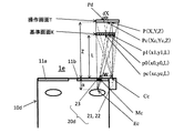
次に、ずれ補正部77bによる位置データの換算処理を詳しく説明する。この換算処理は、位置データのX座標、Y座標に対して個別に行われる。図14は第二実施形態の第一変形例においてずれ補正部77bが位置データのX座標を基準画面K上での位置データのX座標に換算する処理を説明するための図、図15は第二実施形態の第一変形例においてずれ補正部77bが位置データのY座標を基準画面K上での位置データのY座標に換算する処理を説明するための図である。ここで、図14及び図15では、操作画面Tが基準画面Kよりも奥に位置しているとユーザが認識している場合を示している。
Next, the position data conversion process by the
図14及び図15において、点Ccはカメラ部31の中心位置、点Mcは元画面Mの中心位置、点Ecはユーザの瞳の中心位置である。点pcは基準画面Kの中心位置、点Pcは操作画面Tの中心位置である。このとき、点Pc、点pc、点Mc、点Ecは同一直線上にある。また、Wはカメラ部31の中心位置と元画面Mの中心位置とのX軸方向の距離、Hはカメラ部31の中心位置と元画面Mの中心位置とのY軸方向の距離、Lは元画面Mと基準画面KとのZ軸方向の距離、αはユーザの瞳と元画面MとのZ軸方向の距離である。W、H及びαの値は予め記憶部90に記憶されており、Lの値は基準データを生成した際に求められており、記憶部90に記憶されている。
14 and 15, the point Cc is the center position of the
いま、ユーザが操作画面T上の点Pを指で操作したとする。このとき、点Pと点Mcとを結ぶ直線が基準画面Kと交わる点をp0、点Pと点Ccとを結ぶ直線が基準画面Kと交わる点をp1とする。この第一変形例では、位置データ生成部74bは、実際の指の位置を基準画面K上に射影したときのXY座標を指の位置データとして取得する。したがって、位置データ生成部74bは、点Pの位置データとして点p1の位置データを算出している。また、点Pと元画面MとのZ軸方向の距離、すなわち、操作画面Tと元画面MとのZ軸方向の距離Zは、この点Pの位置データを生成した際に用いた画像データと関連付けられている距離データから得られる。点p0は、操作画面T上の点Pに対応する基準画面K上の位置であるので、ずれ補正部77bが行うべきことは、点p1の位置データから点p0の位置データを求めることである。尚、以下では、点Pの位置座標を(X,Y)、点p0の位置座標を(x0,y0)、点pcの位置座標を(xc,yc)、点Pcの座標を(Xc,Yc)、点p1の位置座標を(x1,y1)とする。ここで、点pcは基準画面Kの中心位置であるので、この位置座標(xc,yc)は既知であり、記憶部90に記憶されている。また、点pcと点Ccとを結ぶ直線が操作画面Tを交わる点をPdとし、点Pdと点PとのX軸方向の距離をdX、点Pdと点PとのY軸方向の距離をdYとする。
Now, it is assumed that the user operates a point P on the operation screen T with a finger. At this time, a point where a straight line connecting the point P and the point Mc intersects the reference screen K is p0, and a point where a straight line connecting the point P and the point Cc intersects the reference screen K is p1. In the first modification, the position
x0をXで表す式は次のようにして求めることができる。まず、図14において、三角形pc−Pd−Pcと三角形pc−Cc−Mcに注目すると、dX:W=(Z−L):Lより、
dX=W×(Z−L)/L
である。また、三角形Cc−Pd−Pと三角形Cc−pc−p1に注目すると、{(X−Xc)+dX}:(x1−xc)=Z:Lより、
X−Xc=(x1−xc)×Z/L−dX
=(x1−xc)×Z/L−W×(Z−L)/L
である。更に、三角形Ec−Pc−Pと三角形Ec−pc−p0に注目すると、(X−Xc):(x0−xc)=(Z+α):(L+α)より、
x0−xc=(X−Xc)×(L+α)/(Z+α)
={(x1−xc)×Z/L−W×(Z−L)/L}
×(L+α)/(Z+α)
である。したがって、
x0=(x0−xc)+xc
={(x1−xc)×Z/L−W×(Z−L)/L}
×(L+α)/(Z+α)+xc ・・・・(1)
となる。一方、図15において同様に考えると、y0をYで表す式は、
y0=(y0−yc)+yc
={(y1−yc)×Z/L−H×(Z−L)/L}
×(L+α)/(Z+α)+yc ・・・・(2)
となる。尚、上記(1)式、(2)式はともに、操作画面Tが基準画面Kよりも手前に位置しているとユーザが認識している場合にも成り立つ。
The expression expressing x0 by X can be obtained as follows. First, in FIG. 14, focusing on the triangle pc-Pd-Pc and the triangle pc-Cc-Mc, from dX: W = (Z−L): L,
dX = W × (Z−L) / L
It is. When attention is paid to the triangle Cc-Pd-P and the triangle Cc-pc-p1, {(X-Xc) + dX} :( x1-xc) = Z: L
X−Xc = (x1−xc) × Z / L−dX
= (X1-xc) * Z / L-W * (Z-L) / L
It is. Further, focusing on the triangle Ec-Pc-P and the triangle Ec-pc-p0, from (X-Xc) :( x0-xc) = (Z + α) :( L + α),
x0−xc = (X−Xc) × (L + α) / (Z + α)
= {(X1-xc) * Z / L-W * (ZL) / L}
× (L + α) / (Z + α)
It is. Therefore,
x0 = (x0−xc) + xc
= {(X1-xc) * Z / L-W * (ZL) / L}
× (L + α) / (Z + α) + xc (1)
It becomes. On the other hand, when considering similarly in FIG.
y0 = (y0−yc) + yc
= {(Y1-yc) * Z / LH * (ZL) / L}
× (L + α) / (Z + α) + yc (2)
It becomes. Both the above formulas (1) and (2) are also valid when the user recognizes that the operation screen T is positioned in front of the reference screen K.
ずれ補正部77bは、位置データ生成部74bで生成された点p1の位置データ(x1,y1)の値と、点Pと元画面MとのZ軸方向の距離Zの値とを、上記(1)式、(2)式に代入することにより、点p0の位置データ(x0,y0)を得ることができる。
The
入力制御部76は、ユーザが指で操作を行ったときに、操作判定部73で判定して得られた当該指による操作の内容に関するデータ、及び、ずれ補正部77bで求められた当該指の位置データ(x0,y0)と、記憶部90に記憶されている基準画面K(視認画面S)に関する基準データとに基づいて、当該指による操作に対応する入力指示の内容を認識し、その認識した入力指示の内容に応じて、ディスプレイ装置20に表示する元画面Mの制御を行う。
The
第二実施形態の第一変形例では、ユーザの指の位置が基準画面Kの位置より手前であったり、奥であったりして、ユーザが認識している操作画面Tと、基準画面Kとの間にずれが生じるような場合でも、すれ補正部が、基準画面K上におけるユーザの指の位置を求めて、入力制御部は、その指による指示の内容を正確に認識することができる。尚、本変形例におけるその他の効果は上記第二実施形態と同様である。 In the first modification of the second embodiment, the operation screen T recognized by the user when the position of the user's finger is in front of or behind the reference screen K, and the reference screen K Even when a deviation occurs between the two, the blur correction unit obtains the position of the user's finger on the reference screen K, and the input control unit can accurately recognize the content of the instruction by the finger. The remaining effects of this modification are the same as those of the second embodiment.
尚、第二実施形態の第一変形例では、位置データ生成部74bが、実際にユーザが操作した指の位置を基準画面K上に射影したときのXY座標を指の位置データとして取得しているが、第一実施形態及び第二実施形態でも同様に、位置データ生成部74は、実際にユーザが操作した指の位置を基準画面K上に射影したときのXY座標を指の位置データとして取得するようにしてもよい。
In the first modification of the second embodiment, the position
[第二実施形態の第二変形例]
次に、本発明の第二実施形態の第二変形例である眼鏡型端末について説明する。図23は本発明の第二実施形態の第二変形例である眼鏡型端末の概略平面図であって、ずれ補正部が位置データのX座標を基準画面K上での位置データのX座標に換算する処理を説明するための図である。図24はその眼鏡型端末の概略右側面図であって、ずれ補正部が位置データのY座標を基準画面K上での位置データのY座標に換算する処理を説明するための図である。ここで、図23は図14に対応するものであり、図24は図15に対応するものである。尚、本変形例において、上述した第二実施形態の第一変形例のものと同一の機能を有するものには、同一の符号を付すことにより、その詳細な説明を省略する。
[Second Modification of Second Embodiment]
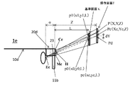
Next, an eyeglass-type terminal that is a second modification of the second embodiment of the present invention will be described. FIG. 23 is a schematic plan view of a glasses-type terminal that is a second modification of the second embodiment of the present invention, in which the shift correction unit converts the X coordinate of the position data to the X coordinate of the position data on the reference screen K. It is a figure for demonstrating the process to convert. FIG. 24 is a schematic right side view of the eyeglass-type terminal, and is a diagram for explaining processing in which the shift correction unit converts the Y coordinate of the position data into the Y coordinate of the position data on the reference screen K. Here, FIG. 23 corresponds to FIG. 14, and FIG. 24 corresponds to FIG. In addition, in this modification, the same code | symbol is attached | subjected to what has the same function as the thing of the 1st modification of 2nd embodiment mentioned above, and the detailed description is abbreviate | omitted.
第二実施形態の第二変形例である眼鏡型端末1eが第二実施形態の第一変形例である眼鏡型端末1bと異なる点は、ディスプレイ装置として、第一実施形態の変形例におけるディスプレイ装置20dを用いた点である。すなわち、このディスプレイ装置20dは、図23及び図24に示すように、小型プロジェクタ21と、光学系22と、眼鏡本体部10dにおける右側のレンズ部11bに埋め込まれたハーフミラー23とを備える。
A difference between an eyeglass-
本変形例の眼鏡型端末1eについて、ずれ補正部77bによる位置データの換算処理は、上述した第二実施形態の第一変形例のものと同様に行われる。尚、本変形例では、ハーフミラー23がレンズ部11bに埋め込まれているが、図23及び図24に示すように、各点(Cc,Mc,Ec,pc,Pc等)や各距離(W,H,L,α等)は第二実施形態の第一変形例におけるものと全く同じに定義される。
For the eyeglass-
本変形例の眼鏡型端末1eの作用・効果は上記第二実施形態の第一変形例のものと同様である。
The operation and effect of the eyeglass-
[第三実施形態]
次に、本発明の第三実施形態である眼鏡型端末について説明する。図16は本発明の第三実施形態である眼鏡型端末の概略ブロック図である。尚、第三実施形態において、上述した第一実施形態のものと同一の機能を有するものには、同一の符号を付すことにより、その詳細な説明を省略する。
[Third embodiment]
Next, the spectacles type terminal which is 3rd embodiment of this invention is demonstrated. FIG. 16 is a schematic block diagram of a glasses-type terminal according to the third embodiment of the present invention. In the third embodiment, components having the same functions as those in the first embodiment described above are denoted by the same reference numerals, and detailed description thereof is omitted.
第三実施形態の眼鏡型端末1cは、図16に示すように、レンズ部を備える眼鏡本体部10と、眼鏡本体部10に設けられたディスプレイ装置(表示装置)20と、ユーザの前方を撮像するための撮像装置30cと、タッチパッド部40と、マイク部50と、スピーカ部60と、制御部70cと、通信部80と、記憶部90とを備える。また、撮像装置30cは、カメラ部31と、画像処理部32と、カメラ制御部33cとを有し、制御部70cは、表示制御部71と、画像データ抽出部72と、操作判定部73と、位置データ生成部74と、基準データ生成部75cと、入力制御部76cと、距離判定部78cとを有する。
As shown in FIG. 16, the eyeglass-
第三実施形態の眼鏡型端末1cが第一実施形態の眼鏡型端末と異なる主な点は、カメラ制御部33cがオートフォーカス制御部331を備えている点、基準データ生成部75cが視認画面に関するデータ(基準データ)として空間内における位置及び大きさを特定できるようなデータを生成する点、及び、制御部70cが、ユーザが視認画面Sに対して指で操作を行ったときに、その指の位置が、基準データを用いて得られる視認画面Sを表す平面から略一定の距離以内だけ離れているかどうかを判定する距離判定部78cを備えている点である。
The main difference between the eyeglass-
オートフォーカス制御部331は、第二実施形態におけるオートフォーカス制御部と同じものであり、撮像範囲内における所定の位置にある被写体に自動的にピントを合わせるようにカメラ部60を制御する。ここで、第三実施形態では、撮像装置30cは、撮像範囲内のどの位置においても、自動的にピントを合わせることができるように、多数のフォーカスポイントを有する。このため、ユーザが視認画面Sに対して指で操作を行っている場合、撮像装置30cは、その操作を行っている指に自動的にピントを合わせ、当該指をピントが合った状態で撮像することができる。また、オートフォーカス制御部331は、自動的にピントが合わせられた被写体を撮像したときに、その撮像した被写体までの距離データを算出する。この算出した距離データは当該画像データと関連付けられる。そして、撮像装置30cで撮像して得られた画像データとそれに関連付けられた距離データは制御部70cに送られる。なお、オートフォーカスの方式としては、被写体に赤外線・超音波などを照射し、その反射波が戻るまでの時間や照射角度により距離を検出するアクティブ方式、或いは、カメラ部31のレンズで捉えた画像を利用して測距を行う位相差検出方式やコントラスト検出方式等のパッシブ方式のいずれであってもよい。
The
基準データ生成部75cは、ユーザが視認画面Sにおける三つの所定位置、例えば視認画面Sの三つの隅において指で操作を行ったときに、操作判定部73で各所定位置における操作が所定の操作であると判定した画像データに基づいて位置データ生成部74が生成した当該各位置における指の位置データと、その指の位置データを生成した際に用いた画像データと関連付けられている距離データとを用いて、当該視認画面Sに関するデータとして三次元空間内における位置及び大きさを特定できるようなデータを生成し、基準データとして記憶部90に記憶する。具体的には、上記各位置について、当該指の位置データ(二次元位置データ)と当該距離データ(一次元位置データ)とに基づいてXYZ座標系における座標情報(三次元的なデータ)を構成し、上記三つの位置におけるXYZ座標情報(三次元的なデータ)を基準データとして用いることができる。また、かかる基準データを用いると、XYZ座標系における視認画面Sを表す平面の方程式を算出することもできる。一般に、こうして特定される視認画面Sを表す平面は必ずしもXY平面と平行になっているわけではない。なお、第三実施形態では、視認画面Sに関する基準データに基づいて得られる視認画面Sに対応する平面を「基準画面」と称することにする。
When the user performs an operation with a finger at three predetermined positions on the visual recognition screen S, for example, at three corners of the visual recognition screen S, the reference
距離判定部78cは、ユーザが視認画面Sに対して指で操作を行った際に撮像装置30cでピントが合った被写体が撮像されたときに、操作判定部73で当該指による操作が所定の操作であると判定された画像データに基づいて位置データ生成部74で生成された指の位置データと、その指の位置データを生成する際に用いた画像データと関連付けられている距離データと、視認画面Sに関する基準データに基づいて得られる視認画面Sに対応する平面(基準画面)とに基づいて、当該指が当該視認画面Sに対応する平面(基準画面)から予め定められた略一定の距離以内に存在するかどうかを判定するものである。指が基準画面から略一定の距離以内に存在するかどうかを判断する際における略一定の距離というのは、ユーザが視認画面Sに対して操作を適正に行っていると認めることができる距離である。ここでは、上記略一定の距離を、例えば約5cmに設定している。これにより、距離判定部78cは、指が基準画面から略一定の距離よりも離れていると判定すると、ユーザが視認画面Sの位置から極端に手前の位置や奥の位置で操作を行っていると認識し、一方、指が基準画面から略一定の距離以内にあると判定すると、ユーザが視認画面Sに対して適正に操作を行っていると認識することになる。
When the user performs an operation with the finger on the visual recognition screen S, the
入力制御部76cは、ユーザが視認画面Sに対して指で操作を行った場合であって距離判定部78cで当該指が基準画面から略一定の距離以内に存在すると判定されたときに、操作判定部73で判定して得られた当該指による操作の内容に関するデータと、その判定で用いられた画像データに基づいて位置データ生成部74で生成された当該指の位置データと、その判定で用いられた画像データと関連付けられている距離データと、記憶部90に記憶されている当該視認画面Sに関する基準データとに基づいて、当該指による操作に対応する入力指示の内容を認識し、その認識した入力指示の内容に応じて、ディスプレイ装置20に表示する元画面Mの制御を行う。
The
次に、第三実施形態の眼鏡型端末1cにおいて基準データを設定する処理について説明する。
Next, processing for setting reference data in the eyeglass-
第三実施形態の眼鏡型端末1cにおける基準データの設定処理の手順を説明するためのフローチャートは、図8に示す第一実施形態のものと同様である。第三実施形態における基準データの設定処理が第一実施形態における基準データの設定処理と異なるのは、撮像装置30cでの処理(ステップS2、S3)と、基準データ生成部75cによる基準データの生成処理(ステップS8)とである。したがって、以下では、図8に示すフローチャートを用いて、第三実施形態における基準データの設定処理のうち第一実施形態における基準データの設定処理と異なる事項について説明する。
The flowchart for explaining the procedure of the reference data setting process in the eyeglass-
まず、表示制御部71は、基準データ設定用の元画面を作成して、ディスプレイ装置20に表示する(S1)。図17は基準データを設定する処理の際に表示される基準データ設定用の元画面Mの例を示す図である。図17(a)の例では、基準データ設定用の元画面Mは文字入力画面201であり、その四隅の位置のうち三つの所定位置に円と数字とを示す画像が追加されている。なお、図17(a)では、文字入力画面201の四隅のうち三つの所定位置に円の画像を表示しているが、図17(b)に示すように、文字入力画面201のキーボード画像210の四隅のうち三つの所定位置に円の画像を表示するようにしてもよい。ステップS1の処理後、制御部70cは、撮像装置30cの撮像動作を開始する(S2)。ユーザは、基準データ設定用の視認画面Sとして、図17(a)に示すように、四隅の位置のうち三つの所定位置に円と数字とを示す画像が追加された文字入力画面201を見ると、この基準データ設定用の視認画面Sにおいて、数字が付された各円に対して数字の順番に指で所定の操作、例えばタップ操作を行う。かかるユーザによる操作は撮像装置30cで撮像される。このとき、オートフォーカス制御部331は、撮像範囲内にある被写体に自動的にピントを合わせるようにカメラ部31を制御し、撮像装置30cはピントが合った被写体を撮像する。また、オートフォーカス制御部331は、自動的にピントが合わせられた被写体を撮像したときに、その撮像した被写体までの距離データを算出し、この算出した距離データを当該画像データと関連付ける。この撮像して得られた画像データは画像処理部32に送られ、画像処理部32は画像データに対して所定の画像処理を施す。そして、その画像処理を施した画像データとそれに関連付けられた距離データとは制御部70cに送られる(S3)。
First, the
ステップS8では、基準データ生成部75cは、ステップS7の処理において位置データ生成部74で生成された、三つの所定位置における指の位置データと、その指の位置データを生成した際に用いた画像データと関連付けられている距離データとを用いて、現在表示されている視認画面Sに関する基準データを生成して記憶部90に記憶する。
In step S8, the reference
次に、第三実施形態の眼鏡型端末1cにおける文字入力の処理について説明する。図18は第三実施形態の眼鏡型端末1cにおける文字入力の処理の手順を説明するためのフローチャートである。ここでは、予めディスプレイ装置20に元画面Mとして文字入力画面200が表示されているものとする。
Next, a character input process in the glasses-
ユーザは、マイク部50から音声で文字入力を行う旨を指示するか、或いはタッチパッド部40を用いた操作等により文字入力を行う旨を指示する。制御部70cは、その指示を受けると、文字入力処理用プログラムを記憶部90から読み出し、図18に示す処理フローにしたがって文字入力の処理を行う。なお、この文字入力の処理は、元画面Mとして文字入力画面200がディスプレイ装置20に表示されたときに自動的に実行されるようにしてもよい。
The user instructs to input characters by voice from the
まず、制御部70cは、現在、ディスプレイ装置20に表示されている元画面Mに対応する視認画面Sに関する基準データが記憶部90に記憶されているかどうかを判断する(S121)。視認画面Sに関する基準データが記憶部90に記憶されていなければ、制御部70cは、基準データ設定処理用プログラムを記憶部90から読み出し、基準データの設定処理を行う(S122)。その後、ステップS121に移行する。なお、本実施形態では、視認画面Sに関する基準データが記憶部90に記憶されていない場合に基準データの設定処理を実行することにしているが、視認画面Sに関する基準データが記憶部90に記憶されている場合でも、ユーザから指示を受けたときに、基準データの設定処理を実行して、再度、基準データを生成するようにしてもよい。
First, the
一方、ステップS121の処理において視認画面Sに関する基準データが記憶部90に記憶されていると判断されると、制御部70cは、撮像装置30cの撮像動作を開始する(S123)。ユーザは、視認画面Sである文字入力画面200のキーボード画像210に対して指で所定の操作、例えばタップ操作を行う。かかるユーザによる操作は撮像装置30cで撮像される。このとき、オートフォーカス制御部331は、撮像範囲内にある被写体に自動的にピントを合わせるようにカメラ部31を制御し、撮像装置30cはピントが合った被写体を撮像する。また、オートフォーカス制御部331は、自動的にピントが合わせられた被写体を撮像したときに、その撮像した被写体までの距離データを算出し、この算出した距離データを当該画像データと関連付ける。この撮像して得られた画像データは画像処理部32に送られ、画像処理部32は画像データに対して所定の画像処理を施す。そして、その画像処理を施した画像データとそれに関連付けられた距離データとは制御部70cに送られる(S124)。
On the other hand, when it is determined that the reference data regarding the viewing screen S is stored in the
次に、画像データ抽出部72は、撮像装置30cで撮像して得られた画像データに基づいて、被写体が指であるかどうかを判断し、指が存在している画像データを抽出する(S125)。次に、操作判定部73は、画像データ抽出部72で抽出された画像データに基づいて当該指による操作が所定の操作(ここでは、タップ操作)であるかどうかを判定する。この判定は予め定めた所定の時間内に行われる。そして、操作判定部73は、当該指による操作がタップ操作であれば、文字入力のための操作が正常に認識されたと判断し、一方、当該指による操作がタップ操作でなければ、文字入力のための操作が正常に認識されなかったと判断する(S126)。操作判定部73は、文字入力のための操作が正常に認識されたと判断すると、当該指による操作の内容に関するデータを記憶部90に記憶すると共に、文字入力のための操作が正常に認識された旨の信号を表示制御部71に送る。表示制御部71は、その信号を受けると、文字入力のための操作が正常に認識されたことを意味する緑色ランプを示す画像を元画面Mに追加して、ディスプレイ装置20に表示する(S128)。なお、表示制御部71は、緑色ランプを示す画像とともに、或いはその画像に代えて、文字入力のための操作が正常に認識されたことを意味する文字や図形を示す画像を元画面Mに追加するようにしてもよい。或いは、上述したように、制御部70cは、文字入力のための操作が正常に認識されたことを意味する画像の表示とともに、若しくは当該画像の表示に代えて、特定の報知音をスピーカ部60から発するようにしてもよい。
Next, the image
一方、操作判定部73は、ステップS126の処理において、予め定めた所定の時間内に文字入力のための操作が正常に認識されなかったと判断すると、その旨の信号を表示制御部71に送る。このとき例えば、予め定めた所定の時間内に画像データ抽出部72から指が存在している画像データが送られてこなかった場合にも、操作判定部73は、タップ操作が正常に認識されなかったと判断する。表示制御部71は、その信号を受けると、文字入力のための操作が正常に認識されなかったことを意味する赤色ランプを示す画像を元画面Mに追加して、ディスプレイ装置20に表示する(S127)。その後は、ステップS133に移行する。なお、このとき、表示制御部71は、赤色ランプを示す画像とともに、或いはその画像に代えて、文字入力のための操作が正常に認識されなかったことを意味する文字や図形を示す画像を元画面Mに追加するようにしてもよい。或いは、上述したように、制御部70cは、文字入力のための操作が正常に認識されなかったことを意味する画像の表示とともに、若しくは当該画像の表示に代えて、特定の報知音をスピーカ部60から発するようにしてもよい。
On the other hand, when the
ステップS128の処理の後、位置データ生成部74は、操作判定部73で指による操作がタップ操作であると判定された画像データに基づいて、撮像装置30cの撮像範囲における当該指(指先)の位置データを生成する(S129)。こうして生成された指の位置データは記憶部90に記憶される。
After the processing in step S128, the position
次に、距離判定部78cは、位置データ生成部74で生成された指の位置データと、その指の位置データを生成する際に用いた画像データと関連付けられている距離データと、記憶部90に記憶されている当該視認画面Sに関する基準データとに基づいて、当該指が当該視認画面Sに対応する平面(基準画面)から予め定められた略一定の距離以内に存在するかどうかを判定する(S130)。距離判定部78cは、指が基準画面から略一定の距離よりも離れていると判定すると、ユーザが視認画面Sに対して適正に操作を行っていないと判断し、その後、ステップS127に移行する。一方、ステップS130の処理において、距離判定部78cは、指が基準画面から略一定の距離以内にあると判定すると、ユーザが視認画面Sに対して適正に操作を行っていると認識し、その後、ステップS131に移行する。
Next, the
ステップS131では、入力制御部76cは、操作判定部73で判定して得られた当該指による操作の内容に関するデータと、位置データ生成部74で生成された当該指の位置データと、その判定で用いられた画像データと関連付けられている距離データと、記憶部90に記憶されている当該視認画面Sに関する基準データとに基づいて、当該指による操作に対応する入力指示の内容を認識する。例えば、ユーザがキーボード画像210における文字キー画像に対して指でタップ操作を行った場合には、入力制御部76cは、その指の位置データから得られる指の位置が、キーボード画像210におけるどの文字キー画像の領域に対応するのかを調べることにより、今回のタップ操作が行われた文字キーを特定し、その特定した文字キーの入力が指示されたことを認識することができる。その後、入力制御部76cは、認識した入力指示の内容に関する信号を表示制御部71に送り、表示制御部71はその入力指示の内容に応じた元画面Mをディスプレイ装置20に表示する(S132)。
In step S131, the
ステップS132又はステップS127の処理の後、制御部70cは、ユーザから文字入力を終了する旨の指示を受けたかどうかを判断する(S133)。文字入力を終了する旨の指示を受けていれば、文字入力の処理が終了する。これに対し、文字入力を終了する旨の指示を受けていなければ、ステップS123に移行し、文字入力の処理を継続する。なお、ユーザは、文字入力を終了する旨の指示を、例えば音声やタッチパッド部40のタッチ操作により行う。
After the process of step S132 or step S127, the
次に、第三実施形態の眼鏡型端末1cにおける画面表示の処理について説明する。図19は第三実施形態の眼鏡型端末1cにおける画面表示の処理の手順を説明するためのフローチャートである。
Next, screen display processing in the eyeglass-
ユーザは、マイク部50から音声で画面表示のための操作を行う旨を指示するか、或いはタッチパッド部40を用いて画面表示のための操作を行う旨を指示する。制御部70cは、その指示を受けると、画面表示処理用プログラムを記憶部90から読み出し、図19に示す処理フローにしたがって画面表示の処理を行う。なお、この画面表示の処理は、元画面Mがディスプレイ装置20に表示されたときに自動的に実行されるようにしてもよい。
The user instructs the
まず、制御部70cは、現在、ディスプレイ装置20に表示されている元画面Mに対応する視認画面Sに関する基準データが記憶部90に記憶されているかどうかを判断する(S141)。視認画面Sに関する基準データが記憶部90に記憶されていなければ、制御部70cは、基準データ設定処理用プログラムを記憶部90から読み出し、基準データの設定処理を行う(S142)。その後、ステップS141に移行する。なお、本実施形態では、視認画面Sに関する基準データが記憶部90に記憶されていない場合に基準データの設定処理を実行することにしているが、視認画面Sに関する基準データが記憶部90に記憶されている場合でも、ユーザから指示を受けたときに、基準データの設定処理を実行して、再度、基準データを生成するようにしてもよい。
First, the
一方、ステップS141の処理において視認画面Sに関する基準データが記憶部90に記憶されていると判断されると、制御部70cは、撮像装置30cの撮像動作を開始する(S143)。ユーザは、視認画面Sに対して指で所望の操作を行う。かかるユーザによる操作は撮像装置30cで撮像される。
On the other hand, when it is determined in the process of step S141 that the reference data regarding the viewing screen S is stored in the
一方、ステップS141の処理において視認画面Sに関する基準データが記憶部90に記憶されていると判断されると、制御部70cは、撮像装置30cの撮像動作を開始する(S143)。ユーザは、視認画面Sである文字入力画面200のキーボード画像210に対して指で所定の操作、例えばタップ操作を行う。かかるユーザによる操作は撮像装置30cで撮像される。このとき、オートフォーカス制御部331は、撮像範囲内にある被写体に自動的にピントを合わせるようにカメラ部31を制御し、撮像装置30cはピントが合った被写体を撮像する。また、オートフォーカス制御部331は、自動的にピントが合わせられた被写体を撮像したときに、その撮像した被写体までの距離データを算出し、この算出した距離データを当該画像データと関連付ける。この撮像して得られた画像データは画像処理部32に送られ、画像処理部32は画像データに対して所定の画像処理を施す。そして、その画像処理を施した画像データとそれに関連付けられた距離データとは制御部70cに送られる(S144)。
On the other hand, when it is determined in the process of step S141 that the reference data regarding the viewing screen S is stored in the
次に、画像データ抽出部72は、撮像装置30cで撮像して得られた画像データに基づいて、被写体が指であるかどうかを判断し、指が存在している画像データを抽出する(S145)。次に、操作判定部73は、画像データ抽出部72で抽出された画像データに基づいて当該指による操作の内容を判定する。そして、操作判定部73は、当該指による操作が正常に認識されたかどうかを判断する(S146)。操作判定部73は、当該指による操作が正常に認識されたと判断すると、当該指による操作の内容に関するデータを記憶部90に記憶すると共に、当該指による操作が正常に認識された旨の信号を表示制御部71に送る。表示制御部71は、その信号を受けると、指による操作が正常に認識されたことを意味する緑色ランプを示す画像を元画面Mに追加して、ディスプレイ装置20に表示する(S148)。なお、表示制御部71は、緑色ランプを示す画像とともに、或いはその画像に代えて、指による操作が正常に認識されたことを意味する文字や図形を示す画像を元画面Mに追加するようにしてもよい。或いは、上述したように、制御部70は、指による操作が正常に認識されたことを意味する画像の表示とともに、若しくは当該画像の表示に代えて、特定の報知音をスピーカ部60から発するようにしてもよい。
Next, the image
一方、操作判定部73は、ステップS146の処理において、指による操作が正常に認識されなかったと判断すると、その旨の信号を表示制御部71に送る。このとき例えば、予め定めた所定の時間内に画像データ抽出部72から指が存在している画像データが送られてこなかった場合にも、操作判定部73は、タップ操作が正常に認識されなかったと判断する。表示制御部71は、その信号を受けると、指による操作が正常に認識されなかったことを意味する赤色ランプを示す画像を元画面Mに追加して、ディスプレイ装置20に表示する(S147)。その後は、ステップS153に移行する。なお、このとき、表示制御部71は、赤色ランプを示す画像とともに、或いはその画像に代えて、指による操作が正常に認識されなかったことを意味する文字や図形を示す画像を元画面Mに追加するようにしてもよい。或いは、上述したように、制御部70cは、指による操作が正常に認識されなかったことを意味する画像の表示とともに、若しくは当該画像の表示に代えて、特定の報知音をスピーカ部60から発するようにしてもよい。
On the other hand, when the
ステップS148の処理の後、位置データ生成部74は、操作判定部73で指による操作の内容が判定された画像データに基づいて、撮像装置30cの撮像範囲における当該指(指先)の位置データを生成する(S149)。こうして生成された指の位置データは記憶部90に記憶される。
After the process of step S148, the position
次に、距離判定部78cは、位置データ生成部74で生成された指の位置データと、その指の位置データを生成する際に用いた画像データと関連付けられている距離データと、記憶部90に記憶されている当該視認画面Sに関する基準データとに基づいて、当該指が当該視認画面Sに対応する平面(基準画面)から予め定められた略一定の距離以内に存在するかどうかを判定する(S150)。距離判定部78cは、指が基準画面から略一定の距離よりも離れていると判定すると、ユーザが視認画面Sに対して適正に操作を行っていないと判断し、その後、ステップS147に移行する。一方、ステップS150の処理において、距離判定部78cは、指が基準画面から略一定の距離以内にあると判定すると、ユーザが視認画面Sに対して適正に操作を行っていると認識し、その後、ステップS151に移行する。
Next, the
ステップS151では、入力制御部76cは、操作判定部73で判定して得られた当該指による操作の内容に関するデータと、位置データ生成部74で生成された当該指の位置データと、その判定で用いられた画像データと関連付けられている距離データと、記憶部90に記憶されている当該視認画面Sに関する基準データとに基づいて、当該指による操作に対応する入力指示の内容を認識する。例えば、ユーザが視認画面Sに対して指でダブルタップ操作を行った場合には、入力制御部76cは、今回の操作がダブルタップ操作であることを特定し、元画面Mを拡大(又は縮小)する旨の指示を受けたことを認識する。その後、入力制御部76cは、認識した指示の内容に関する信号を表示制御部71に送り、表示制御部71はその指示の内容に応じた元画面Mをディスプレイ装置20に表示する(S152)。
In step S151, the
ステップS152又はステップS147の処理の後、制御部70cは、ユーザから画面表示のための操作を終了する旨の指示を受けたかどうかを判断する(S153)。画面表示のための操作を終了する旨の指示を受けていれば、画面表示の処理が終了する。これに対し、画面表示のための操作を終了する旨の指示を受けていなければ、ステップS143に移行し、画面表示の処理を継続する。なお、ユーザは、画面表示のための操作を終了する旨の指示を、例えば音声やタッチパッド部40のタッチ操作により行う。
After the process of step S152 or step S147, the
第三実施形態の眼鏡型端末は、第一実施形態の眼鏡型端末と同様の作用・効果を奏する。特に、第三実施形態では、基準データ生成部が、基準データとして、視認画面Sについて空間内における位置及び大きさを特定できるようなデータを生成することにより、ユーザが、視認画面Sに対する指での操作の際に、例えば視認画面Sの左側の二つの隅についてはその手前側の位置を操作し、視認画面Sの右側の二つの隅についてはその奥側の位置を操作するというような習癖を有する者であっても、そのユーザの習癖に合った基準データを生成することができる。 The eyeglass-type terminal of the third embodiment has the same operations and effects as the eyeglass-type terminal of the first embodiment. In particular, in the third embodiment, the reference data generation unit generates data that can specify the position and size in the space for the viewing screen S as the reference data, so that the user can use his / her finger to the viewing screen S. In the operation, for example, the left side corner of the viewing screen S is operated at the front side, and the right side corner of the viewing screen S is operated at the back side. Even those who have the ability to generate reference data suitable for the user's habits.
尚、第三実施形態の眼鏡型端末においては、ディスプレイ装置として、第一実施形態の変形例におけるディスプレイ装置20dを用いるようにしてもよい。この場合、このディスプレイ装置20dは、図21及び図22に示すように、小型プロジェクタ21と、光学系22と、眼鏡本体部10dにおける右側のレンズ部11bに埋め込まれたハーフミラー23とを備える。
In the glasses-type terminal of the third embodiment, the
[他の実施形態]
尚、本発明は上記の各実施形態及び各変形例に限定されるものではなく、その要旨の範囲内において種々の変形が可能である。
[Other Embodiments]
The present invention is not limited to the above embodiments and modifications, and various modifications can be made within the scope of the gist.
上記の各実施形態及び各変形例では、ユーザが視認画面に対して指で操作を行う場合について説明したが、例えば、ユーザはスタイラスやペン等の入力指示具を用いて視認画面に対して操作を行うようにしてもよい。 In each of the embodiments and the modifications described above, the case where the user performs an operation with the finger on the viewing screen has been described. For example, the user operates the viewing screen using an input instruction tool such as a stylus or a pen. May be performed.
また、上記の各実施形態及び各変形例において、ユーザは、視認画面に対して指でタッチ操作を行う場合に、指先に所定のマークを付しておくようにしてもよい。マークとしては、円や四角形等の単純な図形や記号等を用いることができる。ここで、指先にマークを付す方法としては、マークを直接、指先に描く方法だけでなく、マークを記したシールを指先に貼り付ける方法、マークを記したサック又はリングを指先に装着する方法等を用いることができる。具体的に、図6(a),図7(a)に示すように、視認画面の表側から指でタッチ操作を行う場合には、マークを指の爪側に付しておくようにすればよい。一方、図6(b),図7(b)に示すように、視認画面の表側だけでなく裏側からも指でタッチ操作する場合には、マークを指の爪側と、指先又は指の腹側(指紋のある部分)との両側に付しておくようにすればよい。なお、視認画面の裏側からのみ指でタッチ操作を行う場合には、マークを指先又は指の腹側にだけ付しておくようにしてもよい。この場合、画像データ抽出部は、マークが存在している画像データを、指が存在している画像データとして抽出する。そして、操作判定部は、マークの動きに基づいて指による操作がどのような内容の操作であるかを判定し、位置データ生成部は、マークの位置データを指の位置データとして生成する。実際、画像データの解析・処理に際しては、指自体の認識よりも単純な図形等のマークの認識の方が容易且つ正確に行うことができるので、画像認識の精度の向上を図ることができる。 In each of the above embodiments and modifications, the user may place a predetermined mark on the fingertip when performing a touch operation with the finger on the viewing screen. As the mark, a simple figure such as a circle or a rectangle, a symbol, or the like can be used. Here, as a method of attaching a mark to the fingertip, not only a method of drawing a mark directly on the fingertip, but also a method of sticking a sticker on which the mark is marked, a method of attaching a sack or ring on which the mark is marked, etc. Can be used. Specifically, as shown in FIGS. 6A and 7A, when a touch operation is performed with a finger from the front side of the viewing screen, the mark is attached to the fingernail side. Good. On the other hand, as shown in FIGS. 6 (b) and 7 (b), when a finger touch operation is performed not only from the front side but also from the back side of the viewing screen, the mark is placed on the fingernail side and the fingertip or finger pad. It should be attached to both sides of the side (the part with the fingerprint). Note that when a touch operation is performed with a finger only from the back side of the viewing screen, a mark may be attached only to the fingertip or the abdomen of the finger. In this case, the image data extraction unit extracts image data in which a mark exists as image data in which a finger exists. Then, the operation determination unit determines what kind of operation the operation by the finger is based on the movement of the mark, and the position data generation unit generates the position data of the mark as the position data of the finger. Actually, in the analysis and processing of image data, since the recognition of a mark such as a simple figure can be performed more easily and accurately than the recognition of the finger itself, the accuracy of image recognition can be improved.
また、上記第一、第二及び第三の実施形態、及び第二実施形態の第一変形例では、ディスプレイ装置が眼鏡のレンズと別個に設けられている場合について説明したが、本発明は、これに限定されるものではなく、ディスプレイ装置はレンズと一体的に構成されているものであってもよい。 In the first, second, and third embodiments, and the first modification of the second embodiment, the case where the display device is provided separately from the lens of the spectacles has been described. However, the present invention is not limited to this, and the display device may be configured integrally with a lens.
また、上記第一、第二及び第三の実施形態、及び第二実施形態の第一変形例では、ディスプレイ装置が、表示デバイスを有する小型プロジェクタと、光学系と、ハーフミラーとを備え、ハーフミラーが、眼鏡本体部のレンズ部の前に配置されたプリズムの中に埋め込まれている場合について説明したが、ハーフミラーを、プリズムと一体化し若しくはプリズムに貼り付けるようにしてもよい。更に、上記第一実施形態の変形例及び第二実施形態の第二変形例では、ディスプレイ装置が、表示デバイスを有する小型プロジェクタと、光学系と、ハーフミラーとを備え、ハーフミラーが、眼鏡本体部のレンズ部に埋め込まれている場合について説明したが、ハーフミラーを、レンズ部に貼り付け若しくはレンズ部と一体化するようにしてもよい。 In the first, second and third embodiments and the first modification of the second embodiment, the display device includes a small projector having a display device, an optical system, and a half mirror, Although the case where the mirror is embedded in the prism disposed in front of the lens portion of the spectacle main body has been described, the half mirror may be integrated with the prism or attached to the prism. Further, in the modification of the first embodiment and the second modification of the second embodiment, the display device includes a small projector having a display device, an optical system, and a half mirror, and the half mirror is a spectacle body. However, the half mirror may be attached to the lens unit or integrated with the lens unit.
また、上記の各実施形態及び各変形例では、ディスプレイ装置が、表示デバイスを有する小型プロジェクタと、光学系と、ハーフミラーとを備える場合について説明したが、ハーフミラーの代わりに、光(映像)の一部を反射するホログラムシート又はホログラムフィルムを用いるようにしてもよい。この場合、ホログラムシート又はホログラムフィルムは、眼鏡本体部のレンズ部の一部又は全部に貼り付けられ、又は眼鏡本体部のレンズ部に埋め込まれ若しくは眼鏡本体部のレンズ部と一体化される。これにより、小型プロジェクタからの画像や映像は、光学系を介してホログラムシート又はホログラムフィルムに投影され、ユーザはホログラムシート又はホログラムフィルムによって反射された画像や映像を見ることができる。 In each of the above-described embodiments and modifications, a case has been described in which the display device includes a small projector having a display device, an optical system, and a half mirror. However, light (video) is used instead of the half mirror. A hologram sheet or a hologram film that reflects a part of the film may be used. In this case, the hologram sheet or the hologram film is attached to a part or all of the lens part of the spectacle body part, or is embedded in the lens part of the spectacle body part or integrated with the lens part of the spectacle body part. Thereby, the image and video from the small projector are projected onto the hologram sheet or hologram film via the optical system, and the user can see the image or video reflected by the hologram sheet or hologram film.
また、上記の各実施形態及び各変形例では、ディスプレイ装置に一つの元画面を表示する場合について説明したが、本発明は、これに限定されるものではなく、ディスプレイ装置に二つの元画面を表示するようにしてもよい。この場合、ユーザは二つの視認画面を空中に浮かんでいるように見ることになる。例えば、文字入力画面のキーボード画像を二つに分け、キーボード画像を右側キーボード画像と左側キーボード画像とから構成する場合には、ユーザは、右側キーボード画像と左側キーボード画像を空中に浮かんでいるように認識し、両手の指で文字の入力を行うことができる。 Further, in each of the above embodiments and modifications, the case where one original screen is displayed on the display device has been described, but the present invention is not limited to this, and two original screens are displayed on the display device. You may make it display. In this case, the user sees the two viewing screens as if they are floating in the air. For example, when the keyboard image of the character input screen is divided into two and the keyboard image is composed of the right keyboard image and the left keyboard image, the user seems to float the right keyboard image and the left keyboard image in the air. Recognize and input characters with fingers of both hands.
更に、上記の各実施形態及び各変形例において、二つのディスプレイ装置を設けて、各ディスプレイ装置に異なる元画面を表示するようにしてもよい。特に、一方のディスプレイ装置を右眼用のレンズ部の前に配置し、他方のディスプレイ装置を左眼用のレンズ部の前に配置すると、ユーザは、一方の視認画面を右目で認識し、他方の視認画面を左目で認識することになる。この場合、二つの撮像装置を設け、各撮像装置が各々の視認画面に対して操作を行う指を撮像するようにしてもよい。 Furthermore, in each of the above-described embodiments and modifications, two display devices may be provided to display different original screens on each display device. In particular, when one display device is arranged in front of the right-eye lens unit and the other display device is arranged in front of the left-eye lens unit, the user recognizes one viewing screen with the right eye, Will be recognized by the left eye. In this case, two imaging devices may be provided so that each imaging device images a finger that performs an operation on each viewing screen.
また、上記の各実施形態及び各変形例では、撮像装置の撮像範囲内においてXY座標系を設定し、そのXY座標系の原点が撮像範囲における左下の点である場合について説明したが、XY座標系の原点は撮像範囲における任意の位置に設定することができる。例えば、XY座標系の原点は撮像範囲における左上の点であってもよい。 In each of the above-described embodiments and modifications, the case where the XY coordinate system is set in the imaging range of the imaging apparatus and the origin of the XY coordinate system is the lower left point in the imaging range has been described. The origin of the system can be set at an arbitrary position in the imaging range. For example, the origin of the XY coordinate system may be the upper left point in the imaging range.
また、上記の第二実施形態では、被写体が撮像装置からZ軸方向に沿って略一定の距離だけ離れているかどうかを画像データ抽出部が判断する際における略一定の距離を、撮像装置から約40cm±5cmの範囲内の距離に設定した場合について説明したが、本発明は、これに限定されるものではなく、上記略一定の距離は、例えば、30cm±3cmであってもよいし、或いは50cm±6cm等であってもよい。また、ユーザが上記略一定の距離を自由に変更することができるようにしてもよい。同様に、上記の第三実施形態では、指が基準画面から略一定の距離以内に存在するかどうかを距離判定部が判断する際における略一定の距離を、約5cmに設定した場合について説明したが、本発明は、これに限定されるものではなく、上記略一定の距離は、例えば3cm、6mm等であってもよい。また、ユーザが上記略一定の距離を自由に変更することができるようにしてもよい。 In the second embodiment, the substantially constant distance when the image data extraction unit determines whether or not the subject is separated from the imaging device by a substantially constant distance along the Z-axis direction is approximately equal to the imaging device. Although the case where the distance is set within the range of 40 cm ± 5 cm has been described, the present invention is not limited to this, and the substantially constant distance may be, for example, 30 cm ± 3 cm, or It may be 50 cm ± 6 cm or the like. In addition, the user may be able to freely change the substantially constant distance. Similarly, in the third embodiment described above, a case has been described in which a substantially constant distance is set to about 5 cm when the distance determination unit determines whether or not the finger is within a substantially constant distance from the reference screen. However, the present invention is not limited to this, and the substantially constant distance may be, for example, 3 cm, 6 mm, or the like. In addition, the user may be able to freely change the substantially constant distance.
また、上記の第三実施形態では、基準データ生成部が、ユーザが視認画面における三つの所定位置、例えば視認画面の三つの隅において指で操作を行ったときに、当該各位置における指の位置データと、その指の位置データを生成した際に用いた画像データと関連付けられている距離データとを用いて、上記三つの位置におけるXYZ座標情報を求め、その求めた三つの位置におけるXYZ座標情報を基準データとする場合について説明したが、本発明は、これに限定されるものではなく、基準データ生成部は、使用者が視認画面における少なくとも三つの所定位置において指で操作を行ったときに、当該各位置における指の位置データと、その指の位置データを生成した際に用いた画像データとともに送られた距離データとを用いて、上記少なくとも三つの位置におけるXYZ座標情報を求め、その求めた各位置におけるXYZ座標情報に基づいて基準データを作成するようにしてもよい。例えば、基準データ生成部は、ユーザが例えば視認画面の四つの隅において指で操作を行ったときに、当該各位置における指の位置データと、その指の位置データを生成した際に用いた画像データと関連付けられている距離データとを用いて、上記四つの位置におけるXYZ座標情報を求め、その求めた四つの位置におけるXYZ座標情報に基づいて基準データを生成するようにしてもよい。なお、この場合、基準データ生成部は、上記四つの位置におけるXYZ座標情報を求めたときに、上記四つの位置が同一平面上になければ、所定のアルゴリズムにより上記四つの位置からのずれが最も小さな平面を求め、この求めた平面に基づいて基準データを生成することが望ましい。 In the third embodiment, when the reference data generation unit performs an operation with a finger at three predetermined positions on the viewing screen, for example, at three corners of the viewing screen, the position of the finger at each position. Using the data and distance data associated with the image data used when generating the finger position data, XYZ coordinate information at the three positions is obtained, and XYZ coordinate information at the obtained three positions is obtained. However, the present invention is not limited to this, and the reference data generation unit is operated when the user performs an operation with a finger at at least three predetermined positions on the viewing screen. , Using the position data of the finger at each position and the distance data sent together with the image data used when the position data of the finger was generated, Seeking XYZ coordinate information at the three positions even without, may be creating a reference data based on the XYZ coordinate information in the determined respective positions. For example, when the user performs an operation with a finger at, for example, four corners of the viewing screen, the reference data generation unit generates the finger position data at each position and the image used when the finger position data is generated. The distance data associated with the data may be used to obtain XYZ coordinate information at the four positions, and the reference data may be generated based on the XYZ coordinate information at the obtained four positions. In this case, the reference data generation unit obtains the XYZ coordinate information at the four positions, and if the four positions are not on the same plane, the deviation from the four positions by the predetermined algorithm is the most. It is desirable to obtain a small plane and generate reference data based on the obtained plane.
また、上記の第三実施形態では、基準データ生成部が、ユーザが視認画面における三つの所定位置において指で操作を行ったときに、各指の位置について、当該指の位置データ(二次元位置データ)と当該距離データ(一次元位置データ)とに基づいてXYZ座標系における座標情報(三次元的なデータ)を構成し、上記三つの位置における三次元的なデータを基準データとして用いる場合について説明したが、例えば二つのカメラ部を設け、各カメラ部で被写体を撮像して得られる画像データ(立体画像データ)に基づいて当該被写体の三次元位置データを得ることができる場合には、基準データ生成部は、ユーザが視認画面における三つの所定位置において指で操作を行ったときに得られる各指の位置についての三次元位置データを基準データとして用いるようにしてもよい。 In the third embodiment, when the reference data generation unit performs an operation with a finger at three predetermined positions on the viewing screen, the finger position data (two-dimensional position) Data) and coordinate information (three-dimensional data) in the XYZ coordinate system based on the distance data (one-dimensional position data) and using the three-dimensional data at the three positions as reference data As described above, for example, when two camera units are provided and three-dimensional position data of the subject can be obtained based on image data (stereoscopic image data) obtained by imaging the subject with each camera unit, The data generation unit is based on the three-dimensional position data about the position of each finger obtained when the user performs an operation with the finger at three predetermined positions on the viewing screen. It may be used as the chromatography data.
また、上記の第二実施形態又は第三実施形態では、オートフォーカス制御部が被写体に自動的にピントを合わせるように撮像装置を制御する場合について説明したが、オートフォーカス制御部は、撮像装置からZ軸方向に沿って一定の距離以内にある被写体にだけ自動的にピントを合わせるように撮像装置を制御するようにしてもよい。例えば、撮像装置から1m以内にある被写体にだけピントが合い、撮像装置から1mより遠いところにある被写体にはピントが合わないようにしてもよい。これにより、被写体にピントを合わせるように撮像装置を制御する処理、及び、撮像装置で撮像された画像データの中から指が存在している画像データを抽出する処理を迅速に行うことができる。 In the second embodiment or the third embodiment described above, the case where the autofocus control unit controls the imaging apparatus so as to automatically focus on the subject has been described. The imaging apparatus may be controlled so that only an object within a certain distance along the Z-axis direction is automatically focused. For example, it may be possible to focus only on a subject within 1 m from the imaging apparatus and not to focus on a subject farther than 1 m from the imaging apparatus. Accordingly, it is possible to quickly perform processing for controlling the imaging device to focus on the subject, and processing for extracting image data in which a finger is present from image data captured by the imaging device.
更に、上記の各実施形態及び各変形例では、基準データの設定、文字入力、及び画面表示のための操作を行う場合に、撮像装置での撮影時にピントの合う範囲を狭い範囲に制限する場合について説明したが、本発明はこれに限定されるものではなく、例えば本発明の眼鏡型端末の撮像装置を用いて通常のカメラ撮影を行う場合に、ピントが合う範囲を一定範囲に制限するようにしてもよい。例えば、通常のカメラ撮影を行う場合には、撮像装置から例えば1mより遠く離れた位置にある被写体にはピントが合わないようにしてもよい。また、上述した基準データの設定等のための操作を行っているときや通常のカメラ撮影を行っているときのように、ピントが合う範囲を一定範囲に制限しているときには、制限している旨を第三者に報知する報知手段を備えることが望ましい。この報知手段としては、例えば眼鏡本体部に設けたLED等のライトを点灯して報知したり、眼鏡本体部にその旨のサイン等を表示して報知したりしてもよい。眼鏡型端末では、撮像装置で撮影された周りの人のプライバシーが侵害されるおそれがあり、問題となっているが、本発明では、撮像装置から例えば1mより遠く離れた位置にある被写体にはピントが合わないようにし、また、ピントが合う範囲を一定範囲に制限しているときには、制限している旨を第三者に報知する報知手段を備えることにより、従来の眼鏡型端末で懸念されているプライバシー問題を解決することが可能になる。更に、撮像装置は、本発明の眼鏡型端末がどのような状態にある場合でもピントが合う範囲を一定範囲に制限することができるものであってもよい。また、眼鏡型端末がどのような状態にある場合でもピントが合う範囲を一定範囲に制限している場合、ユーザが眼鏡型端末を装着し、上述した基準データの設定等のための操作や通常のカメラ撮影の操作以外の操作を行っているときにも、或いは、眼鏡型端末がスタンバイ状態のときにも、報知手段はピントが合う範囲を一定範囲に制限している旨を第三者に報知することが望ましい。加えて、例えば撮像装置が動作していないとき、或いは眼鏡型端末が動作していないときに、報知手段により動作していない旨の報知を行うようにすることが望ましい。このときの報知手段による報知は、上述したピントが合う範囲を一定範囲に制限している旨を第三者に報知するときのものと同様のものであってもよいし、例えばLED等のライトの色を変えたりして異なるものにしてもよい。 Furthermore, in each of the above-described embodiments and modifications, when performing operations for setting reference data, inputting characters, and displaying a screen, the range in focus at the time of shooting with the imaging device is limited to a narrow range. However, the present invention is not limited to this. For example, when performing normal camera shooting using the imaging device of the eyeglass-type terminal of the present invention, the focus range is limited to a certain range. It may be. For example, when normal camera shooting is performed, the subject located at a position farther than, for example, 1 m away from the imaging apparatus may not be focused. Moreover, when the range for focusing is limited to a certain range, such as when the above-described operation for setting the reference data is performed, or when normal camera shooting is performed, the limit is set. It is desirable to provide notifying means for notifying a third party of the fact. As this notification means, for example, a light such as an LED provided on the spectacle main body may be turned on for notification, or a sign indicating that may be displayed on the spectacle main body for notification. In the eyeglass-type terminal, there is a possibility that the privacy of the people around the camera photographed by the imaging device may be infringed, which is a problem. However, in the present invention, for a subject located farther than 1 m from the imaging device, for example, When the focus range is limited, and when the focus range is limited to a certain range, there is a concern with conventional spectacle-type terminals by providing notification means for notifying a third party that the focus range is limited. It will be possible to solve privacy issues. Furthermore, the imaging apparatus may be capable of limiting the range in focus to a certain range regardless of the state of the glasses-type terminal of the present invention. In addition, when the range of focus is limited to a certain range regardless of the state of the spectacle-type terminal, the user wears the spectacle-type terminal and performs the above-described operations for setting the reference data, etc. Even when an operation other than the camera shooting operation is performed, or when the glasses-type terminal is in the standby state, the notification means restricts the in-focus range to a certain range to a third party. It is desirable to notify. In addition, for example, when the imaging apparatus is not operating, or when the glasses-type terminal is not operating, it is desirable to notify that the operating unit is not operating. The notification by the notification means at this time may be the same as that used when notifying a third party that the focus range is limited to a certain range, for example, a light such as an LED. You may make it different by changing the color.
また、上記の第二実施形態又は第三実施形態においては、文字入力の処理や画面表示の処理の際に、撮像装置が被写体である指を認識し、その認識した指に自動的且つ連続的にピントを合わせるようにしてもよい。 In the second embodiment or the third embodiment described above, the imaging device recognizes a finger that is a subject during character input processing or screen display processing, and automatically and continuously to the recognized finger. You may make it focus on.
また、上記の各実施形態及び各変形例において、記憶部に、携帯電話、スマートフォン、タブレットやラップトップコンピュータ等の携帯端末についての操作画面や、パーソナルコンピュータ等の情報端末についての操作画面や、照明、テレビ、エアコンやセキュリティシステム等の家庭電気製品についてのリモコン画面や、カーステレオ、カーナビゲーションやエアコン等の電装装置についてのコントロールパネル画面を元画面として記憶しておくようにしてもよい。この場合、ユーザが、音声により又はタッチパッド部を用いた操作等を行うことにより元画面として上記操作画面等をディスプレイ装置に表示させ、その元画面に対応する視認画面に対して指で操作を行ったときに、制御部(遠隔制御部)はその操作の内容を示す指令信号(コマンド)を生成し、通信部を介してその生成した指令信号を上記携帯端末等に無線送信する。これにより、上記携帯端末等をリモートで操作することができる。すなわち、本発明の眼鏡型端末はエアコン等の遠隔制御可能な装置についてのリモートコントローラ(リモコン)として使用することもできる。図20は元画面としてエアコンについてのリモートコントローラの操作部に対応する画面(リモコン画面)を用い、そのリモコン画面に対応する視認画面に対してユーザが操作を行うときの様子を示す図である。図20に示すように、ユーザがその視認画面に対して設定温度を下げることを指示するボタンを指で操作すると、制御部は設定温度を下げる旨のコマンドを生成し、通信部を介してそのコマンドを赤外線通信によりエアコンに送信し、これにより、ユーザはエアコンの設定温度を容易に下げることができる。 In each of the above embodiments and modifications, the storage unit has an operation screen for a mobile terminal such as a mobile phone, a smartphone, a tablet, and a laptop computer, an operation screen for an information terminal such as a personal computer, and illumination. Further, a remote control screen for home electric products such as a TV, an air conditioner and a security system, and a control panel screen for an electrical equipment such as a car stereo, a car navigation system and an air conditioner may be stored as the original screen. In this case, the user causes the display device to display the operation screen or the like as the original screen by performing an operation or the like using voice or the touch pad unit, and operates the viewing screen corresponding to the original screen with a finger. When performed, the control unit (remote control unit) generates a command signal (command) indicating the content of the operation, and wirelessly transmits the generated command signal to the portable terminal or the like via the communication unit. Thereby, the said portable terminal etc. can be operated remotely. That is, the eyeglass-type terminal of the present invention can also be used as a remote controller (remote controller) for a remotely controllable device such as an air conditioner. FIG. 20 is a diagram illustrating a state in which a screen (remote control screen) corresponding to the operation unit of the remote controller for the air conditioner is used as the original screen, and the user performs an operation on the viewing screen corresponding to the remote control screen. As shown in FIG. 20, when the user operates the button for instructing to lower the set temperature on the viewing screen with a finger, the control unit generates a command to lower the set temperature, and the command is sent via the communication unit. The command is transmitted to the air conditioner by infrared communication, which allows the user to easily lower the set temperature of the air conditioner.
また、上記の各実施形態及び各変形例では、本発明の眼鏡型端末を、ユーザが眼鏡をかけるように頭部に装着する場合について説明したが、本発明の眼鏡型端末は、表示装置や撮像装置等を備えるものであれば、耳にかけて使用する端末に限られるものではなく、頭部の例えば、後頭部、前頭部或いは頭頂部にかけて使用するもの、具体的には、ヘッドセット型端末やヘッドマウンテッドディスプレイ(HMD)型端末であってもよい。 Further, in each of the above-described embodiments and modifications, the case where the spectacle-type terminal of the present invention is mounted on the head so that the user wears spectacles has been described. As long as it has an imaging device or the like, it is not limited to a terminal that is used over the ear, but is used over the head, for example, the back of the head, the front of the head, or the top of the head, specifically, a headset type terminal or It may be a head mounted display (HMD) type terminal.
更に、本発明の眼鏡型端末は、眼鏡に取り付けるタイプのものであってもよい。この場合、本発明の眼鏡型端末を眼鏡に取り付けた後に、使用者がその眼鏡をかけることにより、本発明の眼鏡型端末が頭部に装着される。 Furthermore, the eyeglass-type terminal of the present invention may be of a type attached to eyeglasses. In this case, after the spectacle-type terminal of the present invention is attached to the spectacles, the user wears the spectacles, so that the spectacle-type terminal of the present invention is mounted on the head.
以上説明したように、本発明の眼鏡型端末では、入力制御部が、使用者が視認画面に対して指又は入力指示具で操作を行ったときに、操作判定部で判定して得られた当該指又は入力指示具による操作の内容に関するデータ及び位置データ生成部で生成された当該指又は入力指示具の位置データと、記憶部に記憶されている当該視認画面に関する基準データとに基づいて、当該指又は入力指示具による操作に対応する入力指示の内容を認識し、その認識した入力指示の内容に応じて、表示装置に表示する元画面の制御を行う。このため、本発明の眼鏡型端末を用いると、使用者は、通常のスマートフォン端末やタブレット端末と同様に、視認画面に対して操作を行うことにより、文字入力の操作や拡大・縮小等の各種の画面操作を容易且つ正確に行うことができる。したがって、本発明は、使用者が眼鏡のように装着して使用する眼鏡型端末に適用することができる。 As described above, in the glasses-type terminal of the present invention, the input control unit is obtained by the operation determination unit determining when the user performs an operation on the viewing screen with a finger or an input instruction tool. Based on the data regarding the contents of the operation by the finger or the input pointing tool, the position data of the finger or the input pointing tool generated by the position data generating unit, and the reference data regarding the visual screen stored in the storage unit, The content of the input instruction corresponding to the operation by the finger or the input instruction tool is recognized, and the original screen displayed on the display device is controlled according to the recognized content of the input instruction. For this reason, when using the eyeglass-type terminal of the present invention, the user can perform various operations such as character input operation, enlargement / reduction, etc. by operating the viewing screen in the same manner as a normal smartphone terminal or tablet terminal. The screen operation can be performed easily and accurately. Therefore, the present invention can be applied to a spectacle-type terminal that a user wears like spectacles.
1,1a,1b,1c,1d,1e 眼鏡型端末
10,10d 眼鏡本体部
11,11a,11b レンズ部
20,20d ディスプレイ装置(表示装置)
21 小型プロジェクタ
22 光学系
23 ハーフミラー
30,30a,30c 撮像装置
31 カメラ部
32 画像処理部
33,33a,33c カメラ制御部
331 オートフォーカス制御部
40 タッチパッド部
50 マイク部
60 スピーカ部
70,70a,70b,70c 制御部
71 表示制御部
72,72a 画像データ抽出部
73 操作判定部
74,74b 位置データ生成部
75,75c 基準データ生成部
76,76c 入力制御部
77b ずれ補正部
78c 距離判定部
80 通信部
90 記憶部
200 文字入力画面
201 文字入力画面(基準データ設定用の元画面)
210 キーボード画像
220 表示領域
221 検索画面
2211 キーワード入力部
2212 検索結果表示部
1, 1a, 1b, 1c, 1d, 1e Eyeglass-
21 Small projector 22
210
Claims (13)
前記眼鏡本体部に設けられた、前記視認画面に対して使用者が指又は所定の入力指示具で操作を行ったときにその操作を行った指又は入力指示具を撮像する撮像装置と、
使用者が前記視認画面に対して操作を行った指又は入力指示具を前記撮像装置が撮像したときに、その撮像して得られた画像データに基づいて当該指又は入力指示具による操作が各種の操作のうちどのような内容の操作であるのかを判定する操作判定部と、
使用者が前記視認画面に対して操作を行った指又は入力指示具を前記撮像装置が撮像したときに、その撮像して得られた画像データに基づいて前記撮像装置が撮像することができる範囲である撮像範囲における当該指又は入力指示具の位置データを生成する位置データ生成部と、
使用者が前記視認画面における一又は複数の所定位置において指又は入力指示具で操作を行ったときに、前記操作判定部で前記各所定位置における操作が所定の操作であると判定された前記画像データに基づいて前記位置データ生成部で生成された当該指又は入力指示具の位置データを用いて、当該視認画面の位置及び大きさを特定するための当該視認画面に関するデータを生成して基準データとして記憶部に記憶する基準データ生成部と、
使用者が前記視認画面に対して指又は入力指示具で操作を行ったときに、前記操作判定部で判定して得られた当該指又は入力指示具による操作の内容に関するデータ及び前記位置データ生成部で生成された当該指又は入力指示具の位置データと、前記記憶部に記憶されている当該視認画面に関する前記基準データと、当該視認画面に対応する前記元画面に関するデータとに基づいて、前記撮像範囲内で当該視認画面の範囲を特定し、当該指又は入力指示具による操作がその特定した当該視認画面の範囲内のどの位置で行われたのかを調べることにより、当該指又は入力指示具による操作に対応する入力指示の内容を認識し、その認識した入力指示の内容に応じて、前記表示装置に表示する前記元画面の制御を行う入力制御部と、
を備えることを特徴とする眼鏡型端末。 It has a spectacle main body part and a display device provided on the spectacle main body part for displaying an original screen corresponding to a visual screen that appears to be floating in the air to the user, and the user wears like a spectacle. In the glasses-type terminal
An imaging device that is provided in the eyeglass body, and that captures an image of a finger or an input indicator that is operated when a user operates the finger or a predetermined input indicator on the visual recognition screen;
When the imaging device captures an image of a finger or an input pointing tool operated by the user on the viewing screen, various operations by the finger or the input pointing tool are performed based on image data obtained by the imaging. An operation determination unit that determines what kind of operation is the operation of
Range that can be captured by the imaging device based on image data obtained by imaging when the imaging device images a finger or an input pointing tool operated by the user on the visual recognition screen A position data generation unit that generates position data of the finger or the input pointing tool in the imaging range,
When the user performs an operation with a finger or an input pointing tool at one or a plurality of predetermined positions on the visual recognition screen, the operation determination unit determines that the operation at each predetermined position is a predetermined operation. Based on the data, using the position data of the finger or the input pointing tool generated by the position data generation unit, data relating to the viewing screen for specifying the position and size of the viewing screen is generated and the reference data A reference data generation unit to be stored in the storage unit as
When the user performs an operation on the visual recognition screen with a finger or an input instruction tool, the data regarding the contents of the operation by the finger or the input instruction tool obtained by the operation determination unit and the position data generation are obtained. the position data of the finger or input pointing device generated in section, and the reference data relating to the viewing screen stored in the storage unit, based on the data relating to the former screen corresponding to the viewing screen, the By identifying the range of the visual recognition screen within the imaging range and examining at which position within the range of the visual recognition screen the operation performed by the finger or the input instruction tool is performed, the finger or the input instruction tool An input control unit for recognizing the content of the input instruction corresponding to the operation by and controlling the original screen displayed on the display device according to the recognized content of the input instruction;
An eyeglass-type terminal comprising:
前記撮像装置でピントが合った被写体が撮像されたときに、その撮像して得られた画像データに基づいて当該被写体が指又は入力指示具であるかどうかを判断して指又は入力指示具が存在している画像データを抽出する画像データ抽出部が更に備えられており、
前記操作判定部は、前記画像データ抽出部で抽出された画像データに基づいて当該画像データに存在している指又は入力指示具による操作がどのような内容の操作であるのかを判定するものであり、
前記位置データ生成部は、前記操作判定部で指又は入力指示具による操作が所定の操作であると判定された画像データに基づいて、前記撮像範囲における当該指又は入力指示具の位置データを生成するものであることを特徴とする請求項1記載の眼鏡型端末。 The imaging device is configured to focus on a subject at a position of a visual recognition screen recognized by a user,
When a focused subject is imaged by the imaging device, the finger or the input instruction tool determines whether the subject is a finger or an input instruction tool based on image data obtained by the image pickup. An image data extraction unit for extracting existing image data is further provided,
The operation determination unit determines what kind of operation the operation by the finger or the input instruction tool existing in the image data is based on the image data extracted by the image data extraction unit. Yes,
The position data generation unit generates position data of the finger or the input instruction tool in the imaging range based on the image data determined by the operation determination unit as an operation by the finger or the input instruction tool is a predetermined operation. The spectacles-type terminal according to claim 1, wherein
前記撮像装置で自動的にピントが合わせられた被写体が撮像されたときに、その撮像して得られた画像データに基づいて当該被写体が指又は入力指示具であるかどうかを判断し、また、当該画像データとともに送られた距離データに基づいて当該被写体が前記撮像装置から奥行き方向に沿って予め定められた略一定の距離だけ離れているかどうかを判定して、指又は入力指示具が存在している画像データであってその指又は入力指示具が前記撮像装置から奥行き方向に沿って略一定の距離だけ離れているものを抽出する画像データ抽出部が更に備えられており、
前記操作判定部は、前記画像データ抽出部で抽出された画像データに基づいて当該画像データに存在している指又は入力指示具による操作がどのような内容の操作であるのかを判定するものであり、
前記位置データ生成部は、前記操作判定部で指又は入力指示具による操作が所定の操作であると判定された画像データに基づいて、前記撮像範囲における当該指又は入力指示具の前記位置データを生成するものであることを特徴とする請求項1記載の眼鏡型端末。 The imaging apparatus includes an autofocus control unit that can automatically focus on a subject. When an image of a subject that is automatically focused by the autofocus control unit is captured, up to the captured subject The distance data is calculated and the calculated distance data is output together with the image data obtained by imaging,
When a subject automatically focused by the imaging device is imaged, it is determined whether the subject is a finger or an input instruction tool based on the image data obtained by the imaging, Based on the distance data sent together with the image data, it is determined whether the subject is separated from the imaging device by a predetermined distance along the depth direction, and there is a finger or an input instruction tool. An image data extraction unit that extracts the image data that is separated from the imaging device by a substantially constant distance along the depth direction.
The operation determination unit determines what kind of operation the operation by the finger or the input instruction tool existing in the image data is based on the image data extracted by the image data extraction unit. Yes,
The position data generation unit obtains the position data of the finger or the input instruction tool in the imaging range based on the image data determined by the operation determination unit that the operation by the finger or the input instruction tool is a predetermined operation. The spectacles type terminal according to claim 1, wherein the spectacles type terminal is generated.
前記眼鏡本体部に設けられた、被写体に自動的にピントを合わせることができるオートフォーカス制御部を有し、前記オートフォーカス制御部により自動的にピントが合わせられた被写体を撮像したときに、その撮像した被写体までの距離データを算出し、その算出した距離データを当該撮像して得られた画像データとともに出力する撮像装置と、
前記撮像装置で自動的にピントが合わせられた被写体が撮像されたときに、その撮像して得られた画像データに基づいて当該被写体が指又は入力指示具であるかどうかを判断して、指又は入力具が存在している画像データを抽出する画像データ抽出部と、
使用者が前記視認画面に対して操作を行った指又は入力指示具を前記撮像装置が撮像したときに、前記画像データ抽出部で抽出された画像データに基づいて当該指又は入力指示具による操作が各種の操作のうちどのような内容の操作であるのかを判定する操作判定部と、
使用者が前記視認画面に対して操作を行った指又は入力指示具を前記撮像装置が撮像したときに、前記操作判定部で指又は入力指示具による操作が所定の操作であると判定された画像データに基づいて、前記撮像装置が撮像することができる範囲である撮像範囲における当該指又は入力指示具の位置データを生成する位置データ生成部と、
使用者が前記視認画面における少なくとも三つの所定位置において指又は入力指示具で操作を行ったときに、前記操作判定部で前記各所定位置における操作が所定の操作であると判定された前記画像データに基づいて前記位置データ生成部で生成された少なくとも三つの指又は入力指示具の位置データと、それら位置データを生成した際に用いた画像データとともに送られた距離データとを用いて、三次元空間内において当該視認画面に対応する画面である基準画面を特定するデータを生成して基準データとして記憶部に記憶する基準データ生成部と、
前記基準データ生成部で前記基準データが生成された後に、使用者が前記視認画面に対して指又は入力指示具で操作を行った際に前記撮像装置で自動的にピントが合わせられた被写体を撮像したときに、前記操作判定部で指又は入力指示具による当該操作が所定の操作であると判定された画像データに基づいて前記位置データ生成部で生成された指又は入力指示具の位置データと、その指又は入力指示具の位置データを生成する際に用いた画像データと関連付けられている距離データと、前記記憶部に記憶されている当該視認画面に対応する基準画面を特定する基準データとに基づいて、当該指又は入力指示具が前記基準画面から予め定められた略一定の距離範囲以内に位置しているかどうかを判定する距離判定部と、
使用者が前記視認画面に対して指又は入力指示具で操作を行った場合であって前記距離判定部で当該指又は入力指示具が前記基準画面から略一定の距離範囲以内に位置していると判定されたときに、前記操作判定部で判定して得られた当該指又は入力指示具による操作の内容に関するデータと、その判定で用いられた画像データに基づいて前記位置データ生成部で生成された当該指又は入力指示具の位置データと、その判定で用いられた画像データと関連付けられている距離データと、前記記憶部に記憶されている当該視認画面に対応する基準画面を特定する基準データと、当該視認画面に対応する前記元画面に関するデータとに基づいて、前記撮像範囲内で当該視認画面の範囲を特定し、当該指又は入力指示具による操作がその特定した当該視認画面の範囲内のどの位置で行われたのかを調べることにより、当該指又は入力指示具による操作に対応する入力指示の内容を認識し、その認識した入力指示の内容に応じて、前記表示装置に表示する前記元画面の制御を行う入力制御部と、
を備えることを特徴とする眼鏡型端末。 It has a spectacle main body part and a display device provided on the spectacle main body part for displaying an original screen corresponding to a visual screen that appears to be floating in the air to the user, and the user wears like a spectacle. In the glasses-type terminal
An autofocus control unit provided in the eyeglass body unit that can automatically focus on the subject, and when the subject that is automatically focused by the autofocus control unit is imaged, An imaging device that calculates distance data to the imaged subject and outputs the calculated distance data together with image data obtained by imaging;
When a subject that is automatically focused by the imaging device is imaged, it is determined whether the subject is a finger or an input instruction tool based on the image data obtained by the imaging. Or an image data extraction unit for extracting image data in which an input tool exists;
When the imaging device captures an image of a finger or an input pointing tool operated by the user on the visual recognition screen, an operation performed by the finger or the input pointing tool based on the image data extracted by the image data extraction unit An operation determination unit that determines what kind of operation is among various operations ,
When the imaging device captures an image of a finger or an input pointing tool operated by the user on the visual recognition screen, the operation determining unit determines that the operation by the finger or the input pointing tool is a predetermined operation. A position data generation unit that generates position data of the finger or the input pointing tool in an imaging range that is an area that can be captured by the imaging device, based on image data;
The image data in which the operation determining unit determines that the operation at each predetermined position is a predetermined operation when the user performs an operation with a finger or an input instruction tool at at least three predetermined positions on the visual recognition screen. 3D using the position data of at least three fingers or input pointing tools generated by the position data generation unit based on the distance data sent together with the image data used when generating the position data A reference data generation unit that generates data for specifying a reference screen that is a screen corresponding to the viewing screen in the space and stores the data in the storage unit as reference data;
After the reference data is generated by the reference data generation unit, a subject that is automatically focused by the imaging device when the user operates the viewing screen with a finger or an input instruction tool. Position data of the finger or the input pointing tool generated by the position data generating unit based on the image data determined by the operation determining unit that the operation by the finger or the input pointing tool is a predetermined operation when the image is taken And distance data associated with the image data used when generating the position data of the finger or the input pointing tool, and reference data for specifying a reference screen corresponding to the viewing screen stored in the storage unit And a distance determination unit that determines whether or not the finger or the input instruction tool is located within a substantially constant distance range determined in advance from the reference screen;
When the user performs an operation on the visual recognition screen with a finger or an input pointing tool, the finger or the input pointing tool is positioned within a substantially constant distance range from the reference screen in the distance determination unit. generated by the position data generator on the basis and when it is determined, and the data regarding the content of the operation by the obtained the finger or input pointing tool as judged by the operation judgment unit, the image data used in the determination The position data of the finger or input pointing tool that has been made, the distance data associated with the image data used in the determination, and the reference for identifying the reference screen corresponding to the viewing screen stored in the storage unit and data based on the data relating to the former screen corresponding to the viewing screen, to identify the range of the viewing screen within the imaging range, those which operated by the finger or input pointing tool has its particular By examining whether took place at any location within the viewing screen, it recognizes the contents of the input instruction corresponding to the operation by the finger or an input instruction device, according to the content of the input instruction to the recognition, the display An input control unit for controlling the original screen displayed on the apparatus;
An eyeglass-type terminal comprising:
前記リモートコントローラの操作部に対応する画面に対して操作が行われたときにその操作の内容を示す指令信号を生成し、その生成した指令信号を前記遠隔制御可能な装置に無線送信する遠隔制御部を更に備えることを特徴とする請求項1乃至5の何れか一項記載の眼鏡型端末。 The original screen displayed on the display device includes a screen corresponding to the operation unit of the remote controller for the remotely controllable device,
Remote control that generates a command signal indicating the content of the operation when an operation is performed on a screen corresponding to the operation unit of the remote controller, and wirelessly transmits the generated command signal to the remotely controllable device The glasses-type terminal according to claim 1, further comprising a unit.
The user does not wear and use it like glasses, but the user wears and uses it on any part of the head other than the ear. The glasses-type terminal described.
Priority Applications (4)
| Application Number | Priority Date | Filing Date | Title |
|---|---|---|---|
| JP2015110240A JP6041016B2 (en) | 2014-07-25 | 2015-05-29 | Eyeglass type terminal |
| EP15178479.0A EP2978218B1 (en) | 2014-07-25 | 2015-07-27 | Computer display device mounted on eyeglasses |
| US14/809,420 US10191282B2 (en) | 2014-07-25 | 2015-07-27 | Computer display device mounted on eyeglasses |
| US16/214,596 US10585288B2 (en) | 2014-07-25 | 2018-12-10 | Computer display device mounted on eyeglasses |
Applications Claiming Priority (3)
| Application Number | Priority Date | Filing Date | Title |
|---|---|---|---|
| JP2014152019 | 2014-07-25 | ||
| JP2014152019 | 2014-07-25 | ||
| JP2015110240A JP6041016B2 (en) | 2014-07-25 | 2015-05-29 | Eyeglass type terminal |
Publications (3)
| Publication Number | Publication Date |
|---|---|
| JP2016031761A JP2016031761A (en) | 2016-03-07 |
| JP2016031761A5 JP2016031761A5 (en) | 2016-07-14 |
| JP6041016B2 true JP6041016B2 (en) | 2016-12-07 |
Family
ID=53758097
Family Applications (1)
| Application Number | Title | Priority Date | Filing Date |
|---|---|---|---|
| JP2015110240A Active JP6041016B2 (en) | 2014-07-25 | 2015-05-29 | Eyeglass type terminal |
Country Status (3)
| Country | Link |
|---|---|
| US (2) | US10191282B2 (en) |
| EP (1) | EP2978218B1 (en) |
| JP (1) | JP6041016B2 (en) |
Families Citing this family (14)
| Publication number | Priority date | Publication date | Assignee | Title |
|---|---|---|---|---|
| WO2016185634A1 (en) * | 2015-05-21 | 2016-11-24 | 株式会社ソニー・インタラクティブエンタテインメント | Information processing device |
| US9709807B2 (en) * | 2015-11-03 | 2017-07-18 | Motorola Solutions, Inc. | Out of focus notifications |
| JP2017191546A (en) * | 2016-04-15 | 2017-10-19 | ミラマ サービス インク | Medical use head-mounted display, program of medical use head-mounted display, and control method of medical use head-mounted display |
| WO2018008096A1 (en) * | 2016-07-05 | 2018-01-11 | マクセル株式会社 | Information display device and program |
| WO2018158818A1 (en) * | 2017-02-28 | 2018-09-07 | 日本電気株式会社 | Inspection assistance device, inspection assistance method, and recording medium |
| EP3336848B1 (en) | 2017-08-15 | 2023-09-27 | Siemens Healthcare GmbH | Method for operating a medical imaging device and medical imaging device |
| JP2019164420A (en) * | 2018-03-19 | 2019-09-26 | セイコーエプソン株式会社 | Transmission type head-mounted display device, control method of transmission type head-mounted display device, and computer program for control of transmission type head-mounted display device |
| KR102186615B1 (en) * | 2019-03-20 | 2020-12-03 | 주식회사 이랜텍 | Smart Glasses |
| US10798292B1 (en) * | 2019-05-31 | 2020-10-06 | Microsoft Technology Licensing, Llc | Techniques to set focus in camera in a mixed-reality environment with hand gesture interaction |
| CN110989873B (en) * | 2019-11-07 | 2023-06-27 | 浙江工业大学 | Optical imaging system for simulating touch screen |
| JP7031112B1 (en) | 2020-10-13 | 2022-03-08 | 裕行 池田 | Glasses type terminal |
| EP3985486B1 (en) | 2020-10-13 | 2024-04-17 | Hiroyuki Ikeda | Glasses-type terminal |
| JP7080448B1 (en) | 2021-03-08 | 2022-06-06 | 裕行 池田 | Terminal device |
| KR20240028819A (en) * | 2022-08-25 | 2024-03-05 | 한국전자통신연구원 | Smart glasses and operation method thereof |
Family Cites Families (17)
| Publication number | Priority date | Publication date | Assignee | Title |
|---|---|---|---|---|
| JPH075978A (en) * | 1993-06-18 | 1995-01-10 | Sony Corp | Input device |
| JPH07110735A (en) * | 1993-10-14 | 1995-04-25 | Nippon Telegr & Teleph Corp <Ntt> | Fitting type pen input device |
| JP3630746B2 (en) * | 1994-12-05 | 2005-03-23 | キヤノン株式会社 | Image observation device |
| US20090273574A1 (en) | 1995-06-29 | 2009-11-05 | Pryor Timothy R | Programmable tactile touch screen displays and man-machine interfaces for improved vehicle instrumentation and telematics |
| JPH1198227A (en) | 1997-09-22 | 1999-04-09 | Gakuichi Yanagi | Portable remote activation terminal for speech system |
| JP2008009490A (en) * | 2006-06-27 | 2008-01-17 | Konica Minolta Holdings Inc | Information input device |
| JP5163166B2 (en) * | 2008-02-12 | 2013-03-13 | ブラザー工業株式会社 | Image display device |
| JP5250834B2 (en) * | 2008-04-03 | 2013-07-31 | コニカミノルタ株式会社 | Head-mounted image display device |
| JP5179575B2 (en) | 2008-04-30 | 2013-04-10 | パナソニック株式会社 | Scanning image display device, eyeglass-type head mounted display, and automobile |
| JP5293154B2 (en) * | 2008-12-19 | 2013-09-18 | ブラザー工業株式会社 | Head mounted display |
| AU2011220382A1 (en) * | 2010-02-28 | 2012-10-18 | Microsoft Corporation | Local advertising content on an interactive head-mounted eyepiece |
| US9069164B2 (en) | 2011-07-12 | 2015-06-30 | Google Inc. | Methods and systems for a virtual input device |
| JP6123160B2 (en) * | 2012-03-13 | 2017-05-10 | 株式会社ニコン | Electronic device and display device |
| JP2013206412A (en) | 2012-03-29 | 2013-10-07 | Brother Ind Ltd | Head-mounted display and computer program |
| JP2014056462A (en) * | 2012-09-13 | 2014-03-27 | Toshiba Alpine Automotive Technology Corp | Operation device |
| US10013138B2 (en) * | 2012-10-22 | 2018-07-03 | Atheer, Inc. | Method and apparatus for secure data entry using a virtual interface |
| JP6094190B2 (en) * | 2012-12-10 | 2017-03-15 | ソニー株式会社 | Information processing apparatus and recording medium |
-
2015
- 2015-05-29 JP JP2015110240A patent/JP6041016B2/en active Active
- 2015-07-27 US US14/809,420 patent/US10191282B2/en active Active
- 2015-07-27 EP EP15178479.0A patent/EP2978218B1/en active Active
-
2018
- 2018-12-10 US US16/214,596 patent/US10585288B2/en active Active
Also Published As
| Publication number | Publication date |
|---|---|
| US10191282B2 (en) | 2019-01-29 |
| EP2978218A1 (en) | 2016-01-27 |
| JP2016031761A (en) | 2016-03-07 |
| EP2978218B1 (en) | 2023-04-19 |
| US20160025983A1 (en) | 2016-01-28 |
| US20190107724A1 (en) | 2019-04-11 |
| US10585288B2 (en) | 2020-03-10 |
Similar Documents
| Publication | Publication Date | Title |
|---|---|---|
| JP6041016B2 (en) | Eyeglass type terminal | |
| JP6393367B2 (en) | Tracking display system, tracking display program, tracking display method, wearable device using them, tracking display program for wearable device, and operation method of wearable device | |
| KR102494698B1 (en) | Method and apparatus for changing focus of camera | |
| US20180136465A1 (en) | Mobile terminal and controlling method thereof | |
| JP2016031761A5 (en) | ||
| JP6507827B2 (en) | Display system | |
| US20180316911A1 (en) | Information processing apparatus | |
| JP2012079167A (en) | Information processing apparatus, information processing system and information processing method | |
| US11429200B2 (en) | Glasses-type terminal | |
| JP6638392B2 (en) | Display device, display system, display device control method, and program | |
| CN103713387A (en) | Electronic device and acquisition method | |
| JP6740613B2 (en) | Display device, display device control method, and program | |
| US20210400234A1 (en) | Information processing apparatus, information processing method, and program | |
| JP2017062650A (en) | Display system, display unit, information display method, and program | |
| JP6733401B2 (en) | Display system, display device, information display method, and program | |
| US11854444B2 (en) | Display device and display method | |
| JP6765846B2 (en) | Information processing equipment, information processing methods, and programs | |
| TW201807540A (en) | Information processing system, operation method, and operation program | |
| JP7080448B1 (en) | Terminal device | |
| JP7031112B1 (en) | Glasses type terminal | |
| JP2017111537A (en) | Head-mounted display and program for head-mounted display | |
| JP2018085595A (en) | Head-mounted display device and method for controlling the same | |
| JP2015087399A (en) | Presentation system |
Legal Events
| Date | Code | Title | Description |
|---|---|---|---|
| A521 | Request for written amendment filed |
Free format text: JAPANESE INTERMEDIATE CODE: A523 Effective date: 20160530 |
|
| A621 | Written request for application examination |
Free format text: JAPANESE INTERMEDIATE CODE: A621 Effective date: 20160530 |
|
| A871 | Explanation of circumstances concerning accelerated examination |
Free format text: JAPANESE INTERMEDIATE CODE: A871 Effective date: 20160530 |
|
| A975 | Report on accelerated examination |
Free format text: JAPANESE INTERMEDIATE CODE: A971005 Effective date: 20160622 |
|
| A131 | Notification of reasons for refusal |
Free format text: JAPANESE INTERMEDIATE CODE: A131 Effective date: 20160627 |
|
| A521 | Request for written amendment filed |
Free format text: JAPANESE INTERMEDIATE CODE: A523 Effective date: 20160823 |
|
| TRDD | Decision of grant or rejection written | ||
| A01 | Written decision to grant a patent or to grant a registration (utility model) |
Free format text: JAPANESE INTERMEDIATE CODE: A01 Effective date: 20161011 |
|
| A61 | First payment of annual fees (during grant procedure) |
Free format text: JAPANESE INTERMEDIATE CODE: A61 Effective date: 20161024 |
|
| R150 | Certificate of patent or registration of utility model |
Ref document number: 6041016 Country of ref document: JP Free format text: JAPANESE INTERMEDIATE CODE: R150 |
|
| R250 | Receipt of annual fees |
Free format text: JAPANESE INTERMEDIATE CODE: R250 |