EP2804093A1 - A method for stabilization and a system thereto - Google Patents
A method for stabilization and a system thereto Download PDFInfo
- Publication number
- EP2804093A1 EP2804093A1 EP13167460.8A EP13167460A EP2804093A1 EP 2804093 A1 EP2804093 A1 EP 2804093A1 EP 13167460 A EP13167460 A EP 13167460A EP 2804093 A1 EP2804093 A1 EP 2804093A1
- Authority
- EP
- European Patent Office
- Prior art keywords
- display
- electronic device
- image signal
- user
- gaze
- Prior art date
- Legal status (The legal status is an assumption and is not a legal conclusion. Google has not performed a legal analysis and makes no representation as to the accuracy of the status listed.)
- Withdrawn
Links
Images


Classifications
-
- G—PHYSICS
- G09—EDUCATION; CRYPTOGRAPHY; DISPLAY; ADVERTISING; SEALS
- G09G—ARRANGEMENTS OR CIRCUITS FOR CONTROL OF INDICATING DEVICES USING STATIC MEANS TO PRESENT VARIABLE INFORMATION
- G09G5/00—Control arrangements or circuits for visual indicators common to cathode-ray tube indicators and other visual indicators
- G09G5/003—Details of a display terminal, the details relating to the control arrangement of the display terminal and to the interfaces thereto
- G09G5/005—Adapting incoming signals to the display format of the display terminal
-
- G—PHYSICS
- G06—COMPUTING; CALCULATING OR COUNTING
- G06F—ELECTRIC DIGITAL DATA PROCESSING
- G06F3/00—Input arrangements for transferring data to be processed into a form capable of being handled by the computer; Output arrangements for transferring data from processing unit to output unit, e.g. interface arrangements
- G06F3/01—Input arrangements or combined input and output arrangements for interaction between user and computer
- G06F3/011—Arrangements for interaction with the human body, e.g. for user immersion in virtual reality
- G06F3/013—Eye tracking input arrangements
-
- G—PHYSICS
- G02—OPTICS
- G02B—OPTICAL ELEMENTS, SYSTEMS OR APPARATUS
- G02B27/00—Optical systems or apparatus not provided for by any of the groups G02B1/00 - G02B26/00, G02B30/00
- G02B27/0093—Optical systems or apparatus not provided for by any of the groups G02B1/00 - G02B26/00, G02B30/00 with means for monitoring data relating to the user, e.g. head-tracking, eye-tracking
-
- G—PHYSICS
- G06—COMPUTING; CALCULATING OR COUNTING
- G06F—ELECTRIC DIGITAL DATA PROCESSING
- G06F3/00—Input arrangements for transferring data to be processed into a form capable of being handled by the computer; Output arrangements for transferring data from processing unit to output unit, e.g. interface arrangements
- G06F3/14—Digital output to display device ; Cooperation and interconnection of the display device with other functional units
- G06F3/1454—Digital output to display device ; Cooperation and interconnection of the display device with other functional units involving copying of the display data of a local workstation or window to a remote workstation or window so that an actual copy of the data is displayed simultaneously on two or more displays, e.g. teledisplay
-
- G—PHYSICS
- G09—EDUCATION; CRYPTOGRAPHY; DISPLAY; ADVERTISING; SEALS
- G09G—ARRANGEMENTS OR CIRCUITS FOR CONTROL OF INDICATING DEVICES USING STATIC MEANS TO PRESENT VARIABLE INFORMATION
- G09G5/00—Control arrangements or circuits for visual indicators common to cathode-ray tube indicators and other visual indicators
- G09G5/12—Synchronisation between the display unit and other units, e.g. other display units, video-disc players
-
- G—PHYSICS
- G09—EDUCATION; CRYPTOGRAPHY; DISPLAY; ADVERTISING; SEALS
- G09G—ARRANGEMENTS OR CIRCUITS FOR CONTROL OF INDICATING DEVICES USING STATIC MEANS TO PRESENT VARIABLE INFORMATION
- G09G2320/00—Control of display operating conditions
- G09G2320/02—Improving the quality of display appearance
- G09G2320/0261—Improving the quality of display appearance in the context of movement of objects on the screen or movement of the observer relative to the screen
-
- G—PHYSICS
- G09—EDUCATION; CRYPTOGRAPHY; DISPLAY; ADVERTISING; SEALS
- G09G—ARRANGEMENTS OR CIRCUITS FOR CONTROL OF INDICATING DEVICES USING STATIC MEANS TO PRESENT VARIABLE INFORMATION
- G09G5/00—Control arrangements or circuits for visual indicators common to cathode-ray tube indicators and other visual indicators
- G09G5/14—Display of multiple viewports
Definitions
- Embodiments herein relate to methods for stabilization for use in a display system, and to a display system.
- a modern mobile electronic device often comprises a camera and may be used to create a so called keyhole display.
- the mobile device and its camera mimics a small keyhole through which a user looks at.
- a problem that occurs if the keyhole display is to be displayed on a remote display for other users to look at, in real-time or at a later occurrence, is that every little movement of the mobile device, and hence of the camera, will be transferred to the remote display and the keyhole as displayed on the remote display will look jerky and erratic, and it is often difficult to watch for any longer period, i.e. due to motion sickness.
- the display system comprises a first electronic device and a second electronic device.
- the first electronic device comprises a first display and a gaze tracking unit configured to track a gaze of a user of the first device.
- the first device is arranged to send an image signal to the second device.
- the second device comprises a second display.
- methods comprises sending the image signal from the first device to the second device, controlling the image signal by a control unit, depending on the tracked gaze of the user, displaying the controlled image signal on the second display such that, when the user focuses on an object of a view of the first display, the object of the view on the second display is cropped and stabilized.
- the first electronic device comprises a camera unit sending image signals to the first display.
- image signals received by the camera unit are sent to the second display.
- a display system comprising at least a first electronic device and a second electronic device.
- the first electronic device is arranged to send an image signal to the second electronic device.
- the first electronic device comprises a first display and a gaze tracking unit configured to track a gaze of a user of the first electronic device.
- the second electronic device comprises a second display.
- the system comprises a control unit configured to control the image signal, depending on the tracked gaze of the user, such that, when the user focuses on an object of a view of the first display, the object of the view is cropped and stabilized when displayed on the second display.
- control unit is comprised in the first electronic device.
- the first electronic device further comprises a camera unit configured to send image signals to the first display.
- the first electronic device is configured to send image signals to the second display.
- the image signal received on the second display comprises information of a geographical position of an object shown in the first display.
- the first electronic device comprises means for determining a geographical position
- the image signal received in the second display comprises information of the geographical position of the first electronic device
- a system 200 comprises a first electronic device 201 and a second electronic device 204.
- the first electronic device 201 may for example be a mobile phone, a tablet or the like.
- the first electronic device 201 comprises a first display 202 and a gaze tracking unit 203 configured to track a gaze of a user 301 of the first device 201.
- the gaze tracking unit 203 may be any suitable gaze tracking equipment available.
- the first device 201 is arranged to send an image signal to the second device 204 comprising a second display 205.
- the first electronic device 201 comprises a camera unit 207 and a display unit 202 adapted to display image signals received from the camera unit 207.
- the second electronic device 202 comprises a second display unit 205 for displaying image signals.
- a view shown on the second display 205 is controlled by a control unit 206 comprised in the first device 201.
- the control unit 206 may as well be comprised in the second device 204, or may be provided separately. Controlling depends on the tracked gaze of the user 301.
- the view is controlled on the second display 205 such that, when the user 301 focuses on an object of a view of the first display 201, the object of the view is cropped and stabilized when displayed on the second display 205.
- Image signals may be sent from the first electronic device 201 to the second display 205.
- the first electronic device 201 may comprise a camera unit 207 sending image signals to the first display.
- the method may further comprise sending image signals received by the camera unit to the second display 205.
- the image signal received on the second display 205 may comprise information of a geographical position of an object shown in the first display 202.
- the method thus utilizes gaze-tracking technique, thus what a user 301 focuses on, for picking out objects of interest and define boundaries for stabilizing a keyhole view as represented by a first electronic device 201 that may be a mobile device or a tablet camera, and a thereto related display, being streamed to and displayed on a remote second display 205 present in a second electronic device 204.
- a first electronic device 201 may be a mobile device or a tablet camera, and a thereto related display, being streamed to and displayed on a remote second display 205 present in a second electronic device 204.
- the received image signals may for example be displayed on a part of the display unit of the second electronic device. Another image signals may simultaneously be displayed on the display unit of the second electronic device. Alternatively, the received image may be displayed solely on the display unit of the second electronic device.
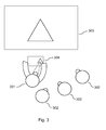
- FIG. 3 A possible exemplary use case is shown in Figure 3 .
- a user 301 is showing a holiday photo of an object for her friends 302 on a TV 303 from a tablet 304. There is a discussion whether there is, for example, a clock on all four sides of the object or only on two.
- the user 301 raises the tablet 304 which is set to be a trigger of Google Street view and start streaming a modified view of what is shown on the device 304 to the TV 303.
- the device will have a better understanding of what the user is actually looking at through the keyhole and thereby be able to define cropping boundaries, that may slowly grow and shrink dynamically based on gaze-tracking input, and that can be used to even further improve image stabilization for the video being streamed to the remote display.
- watching the keyhole as displayed on the remote display will then be much more enjoyable.
- the system exemplified comprises a first electronic device 201 and a second electronic device 204.
- the first electronic device 201 is arranged to send image signals to the second device 204.
- the first electronic device 201 comprises a camera unit 207, and a first display unit 202 adapted to display image signals received from the camera unit 207.
- Received image signals may be sent from the first electronic device 201 to the second electronic device 202.
- the second electronic device 202 comprises a display unit 205 for displaying image signals and a receiving unit for receiving image signals sent by the first electronic device.
- the system 200 comprises a control unit 206 configured to control a view shown on the second display by the first device, depending on the tracked gaze of the user, which view is controlled on the second display such that, when the user focuses on an object of a view of the first display, the object of the view is cropped and stabilized when displayed on the second display.
- the control unit 206 may be comprised either in the first electronic device 201, the second electronic device 204, or may be provided separately.
- the image signal received on the second display 205 may comprise information of a geographical position of an object shown in the first display 202.
- the first electronic device 201 may comprise means for determining a geographical position, and the image signal received in the second display 205 may comprise information of the geographical position of the first electronic device.
Abstract
Description
- Embodiments herein relate to methods for stabilization for use in a display system, and to a display system.
- A modern mobile electronic device often comprises a camera and may be used to create a so called keyhole display. The mobile device and its camera mimics a small keyhole through which a user looks at. A problem that occurs if the keyhole display is to be displayed on a remote display for other users to look at, in real-time or at a later occurrence, is that every little movement of the mobile device, and hence of the camera, will be transferred to the remote display and the keyhole as displayed on the remote display will look jerky and erratic, and it is often difficult to watch for any longer period, i.e. due to motion sickness.
- Even though existing image stabilization techniques may be used to stabilize a view shown as described above, the problems mentioned may still be present. An object of embodiments herein is to provide improved methods for stabilization. In embodiments herein, methods for stabilization for use in a display system is provided. The display system comprises a first electronic device and a second electronic device. The first electronic device comprises a first display and a gaze tracking unit configured to track a gaze of a user of the first device. The first device is arranged to send an image signal to the second device. The second device comprises a second display. In embodiments herein, methods comprises sending the image signal from the first device to the second device, controlling the image signal by a control unit, depending on the tracked gaze of the user, displaying the controlled image signal on the second display such that, when the user focuses on an object of a view of the first display, the object of the view on the second display is cropped and stabilized.
- In still other embodiments, the first electronic device comprises a camera unit sending image signals to the first display.
- In still other embodiments, image signals received by the camera unit are sent to the second display.
- In other embodiments herein, the image signal received by the second electronic device comprises information of a geographical position of an object shown in the first display.
- In other embodiments herein, a display system comprising at least a first electronic device and a second electronic device is provided. The first electronic device is arranged to send an image signal to the second electronic device. The first electronic device comprises a first display and a gaze tracking unit configured to track a gaze of a user of the first electronic device. The second electronic device comprises a second display. The system comprises a control unit configured to control the image signal, depending on the tracked gaze of the user, such that, when the user focuses on an object of a view of the first display, the object of the view is cropped and stabilized when displayed on the second display.
- In still other embodiments herein, the control unit is comprised in the first electronic device.
- In other embodiments herein, the control unit is comprised in the second electronic device.
- In other embodiments herein, the first electronic device further comprises a camera unit configured to send image signals to the first display.
- In still other embodiments herein, the first electronic device is configured to send image signals to the second display.
- In still other embodiments herein, the image signal received on the second display comprises information of a geographical position of an object shown in the first display.
- In other embodiments herein, the first electronic device comprises means for determining a geographical position, and the image signal received in the second display comprises information of the geographical position of the first electronic device.
- Examples of embodiments herein are described in more detail with reference to attached drawings in which:
-
Figure 1 is a flow chart. -
Figure 2 shows a display system. -
Figure 3 shows an example of a proposed method. - Embodiments herein will be exemplified in the following detailed non-limiting description.
- With reference to
Figure 1 and2 , an exemplified method for use in adisplay system 200 will now be described. Asystem 200 comprises a firstelectronic device 201 and a secondelectronic device 204. The firstelectronic device 201 may for example be a mobile phone, a tablet or the like. The firstelectronic device 201 comprises afirst display 202 and agaze tracking unit 203 configured to track a gaze of auser 301 of thefirst device 201. Thegaze tracking unit 203 may be any suitable gaze tracking equipment available. Thefirst device 201 is arranged to send an image signal to thesecond device 204 comprising asecond display 205. The firstelectronic device 201 comprises acamera unit 207 and adisplay unit 202 adapted to display image signals received from thecamera unit 207. The secondelectronic device 202 comprises asecond display unit 205 for displaying image signals. In an exemplified method a view shown on thesecond display 205 is controlled by acontrol unit 206 comprised in thefirst device 201. Thecontrol unit 206 may as well be comprised in thesecond device 204, or may be provided separately. Controlling depends on the tracked gaze of theuser 301. The view is controlled on thesecond display 205 such that, when theuser 301 focuses on an object of a view of thefirst display 201, the object of the view is cropped and stabilized when displayed on thesecond display 205. Image signals may be sent from the firstelectronic device 201 to thesecond display 205. The firstelectronic device 201 may comprise acamera unit 207 sending image signals to the first display. The method may further comprise sending image signals received by the camera unit to thesecond display 205. The image signal received on thesecond display 205 may comprise information of a geographical position of an object shown in thefirst display 202. - The method thus utilizes gaze-tracking technique, thus what a
user 301 focuses on, for picking out objects of interest and define boundaries for stabilizing a keyhole view as represented by a firstelectronic device 201 that may be a mobile device or a tablet camera, and a thereto related display, being streamed to and displayed on a remotesecond display 205 present in a secondelectronic device 204. - The received image signals may for example be displayed on a part of the display unit of the second electronic device. Another image signals may simultaneously be displayed on the display unit of the second electronic device. Alternatively, the received image may be displayed solely on the display unit of the second electronic device.
- For example, the specific form of a building, or any other shape shown in the display may be recognized in both devices, and the recognized shape may be used when adapting the image shown in the second device, i.e. by zooming or cutting the view. A possible exemplary use case is shown in
Figure 3 . Auser 301 is showing a holiday photo of an object for herfriends 302 on a TV 303 from atablet 304. There is a discussion whether there is, for example, a clock on all four sides of the object or only on two. Theuser 301 raises thetablet 304 which is set to be a trigger of Google Street view and start streaming a modified view of what is shown on thedevice 304 to theTV 303. Since the photo is geo tagged, the Street View application is started at the location where the photo was taken close to the object and allows panning around by moving thetablet 304 around. Since theuser 301 is constantly and eagerly looking at the object on thetablet 304 the device stabilizes the viewing experience on theTV 303 on that part by cropping the view and not showing the entire screen. That makes the viewing experience much better. By adding gaze-tracking, i.e. using mobile device and tablet front-facing camera and tracking the eye's of the user controlling the keyhole, the device will have a better understanding of what the user is actually looking at through the keyhole and thereby be able to define cropping boundaries, that may slowly grow and shrink dynamically based on gaze-tracking input, and that can be used to even further improve image stabilization for the video being streamed to the remote display. Thus, watching the keyhole as displayed on the remote display will then be much more enjoyable. - Now returning to
Figure 2 , an example of adisplay system 200 is shown. The system exemplified comprises a firstelectronic device 201 and a secondelectronic device 204. The firstelectronic device 201 is arranged to send image signals to thesecond device 204. The firstelectronic device 201 comprises acamera unit 207, and afirst display unit 202 adapted to display image signals received from thecamera unit 207. Received image signals may be sent from the firstelectronic device 201 to the secondelectronic device 202. The secondelectronic device 202 comprises adisplay unit 205 for displaying image signals and a receiving unit for receiving image signals sent by the first electronic device. Thesystem 200 comprises acontrol unit 206 configured to control a view shown on the second display by the first device, depending on the tracked gaze of the user, which view is controlled on the second display such that, when the user focuses on an object of a view of the first display, the object of the view is cropped and stabilized when displayed on the second display. Thecontrol unit 206 may be comprised either in the firstelectronic device 201, the secondelectronic device 204, or may be provided separately. The image signal received on thesecond display 205 may comprise information of a geographical position of an object shown in thefirst display 202. The firstelectronic device 201 may comprise means for determining a geographical position, and the image signal received in thesecond display 205 may comprise information of the geographical position of the first electronic device. - The embodiments herein are not limited to the above described examples. Various alternatives, modifications and equivalents may be used. Therefore, this disclosure should not be limited to the specific form set forth herein. This disclosure is limited only by the appended claims and other embodiments than the mentioned above are equally possible within the scope of the claims.
Claims (10)
- A method for stabilization for use in a display system (200), the display system (200) comprising a first electronic device (201) and a second electronic device (202),
the first electronic device (201) comprising a first display (202) and a gaze tracking unit (203) configured to track a gaze of a user (301) of the first device, the first device (201) being arranged to send an image signal to the second device (204), the second device (204) comprising a second display (205),
the method comprising:- sending (101) the image signal from the first device (201) to the second device (204),- controlling (102) the image signal by a control unit (206), depending on the tracked gaze of the user (201),- displaying (103) the controlled image signal on the second display (104) such that, when the user (201) focuses on an object of a view of the first display (202), the object of the view on the second display (104) is cropped and stabilized. - The method according to claim 1, wherein the first electronic device (201) comprises a camera unit, the method further comprising:- sending image signals received by the camera unit to the first display.
- The method according to claim 1 or 2, further comprising:- sending image signals received by the camera unit to the second electronic device (204).
- The method according to any of claims 1-3, wherein the image signal received by the second electronic device (204) comprises information of a geographical position of an object shown in the first display (202).
- A display system (200) comprising at least a first electronic device (201), and a second electronic device (204), the first electronic device (201) being arranged to send an image signal to the second electronic device (204), and wherein the first electronic device (201) comprises a first display (202) and a gaze tracking unit (203) configured to track a gaze of a user (301) of the first electronic device (201), and wherein the second electronic device (204) comprises a second display (205),
wherein the system (200) comprises a control unit (206) configured to control the image signal, depending on the tracked gaze of the user (201), such that, when the user (201) focuses on an object of a view of the first display (202), the object of the view is cropped and stabilized when displayed on the second display. - The system according to claim 5, wherein the control unit (206) is comprised in the first electronic device (201).
- The system according to claim 5, wherein the control unit (206) is comprised in the second electronic device (204).
- The system according to any of claims 5-7, wherein the first electronic device (201) further comprises a camera unit (207) configured to send image signals to the first display (202).
- The system according to any of claims 5-8, wherein the image signal received on the second display comprises information of a geographical position of an object shown in the first display.
- The system according to any of claims 5-9, wherein the first electronic device (201) comprises means for determining a geographical position, and the image signal received in the second display (205) comprises information of the geographical position of the first electronic device (201).
Priority Applications (3)
| Application Number | Priority Date | Filing Date | Title |
|---|---|---|---|
| EP13167460.8A EP2804093A1 (en) | 2013-05-13 | 2013-05-13 | A method for stabilization and a system thereto |
| US14/252,083 US9361854B2 (en) | 2013-05-13 | 2014-04-14 | Method for stabilization and a system thereto |
| PCT/IB2014/061388 WO2014184730A1 (en) | 2013-05-13 | 2014-05-13 | A method for stabilization and a system thereto |
Applications Claiming Priority (1)
| Application Number | Priority Date | Filing Date | Title |
|---|---|---|---|
| EP13167460.8A EP2804093A1 (en) | 2013-05-13 | 2013-05-13 | A method for stabilization and a system thereto |
Publications (1)
| Publication Number | Publication Date |
|---|---|
| EP2804093A1 true EP2804093A1 (en) | 2014-11-19 |
Family
ID=48576720
Family Applications (1)
| Application Number | Title | Priority Date | Filing Date |
|---|---|---|---|
| EP13167460.8A Withdrawn EP2804093A1 (en) | 2013-05-13 | 2013-05-13 | A method for stabilization and a system thereto |
Country Status (3)
| Country | Link |
|---|---|
| US (1) | US9361854B2 (en) |
| EP (1) | EP2804093A1 (en) |
| WO (1) | WO2014184730A1 (en) |
Cited By (1)
| Publication number | Priority date | Publication date | Assignee | Title |
|---|---|---|---|---|
| EP3109733A1 (en) * | 2015-06-22 | 2016-12-28 | Nokia Technologies Oy | Content delivery |
Citations (4)
| Publication number | Priority date | Publication date | Assignee | Title |
|---|---|---|---|---|
| WO2011100436A1 (en) * | 2010-02-10 | 2011-08-18 | Lead Technology Capital Management, Llc | System and method of determining an area of concentrated focus and controlling an image displayed in response |
| US20110298936A1 (en) * | 2010-06-07 | 2011-12-08 | Sony Corporation | Image stabilization device, image stabilization method, and program |
| US20120038678A1 (en) * | 2010-08-13 | 2012-02-16 | Lg Electronics Inc. | Mobile terminal, display device and controlling method thereof |
| US20120146891A1 (en) * | 2010-12-08 | 2012-06-14 | Sony Computer Entertainment Inc. | Adaptive displays using gaze tracking |
Family Cites Families (6)
| Publication number | Priority date | Publication date | Assignee | Title |
|---|---|---|---|---|
| US7306337B2 (en) * | 2003-03-06 | 2007-12-11 | Rensselaer Polytechnic Institute | Calibration-free gaze tracking under natural head movement |
| US20110292181A1 (en) * | 2008-04-16 | 2011-12-01 | Canesta, Inc. | Methods and systems using three-dimensional sensing for user interaction with applications |
| US9069164B2 (en) | 2011-07-12 | 2015-06-30 | Google Inc. | Methods and systems for a virtual input device |
| US8988350B2 (en) * | 2011-08-20 | 2015-03-24 | Buckyball Mobile, Inc | Method and system of user authentication with bioresponse data |
| US8990843B2 (en) * | 2012-10-26 | 2015-03-24 | Mobitv, Inc. | Eye tracking based defocusing |
| US9661328B2 (en) * | 2013-03-15 | 2017-05-23 | Arris Enterprises, Inc. | Method of bit allocation for image and video compression using perceptual guidance |
-
2013
- 2013-05-13 EP EP13167460.8A patent/EP2804093A1/en not_active Withdrawn
-
2014
- 2014-04-14 US US14/252,083 patent/US9361854B2/en active Active
- 2014-05-13 WO PCT/IB2014/061388 patent/WO2014184730A1/en active Application Filing
Patent Citations (4)
| Publication number | Priority date | Publication date | Assignee | Title |
|---|---|---|---|---|
| WO2011100436A1 (en) * | 2010-02-10 | 2011-08-18 | Lead Technology Capital Management, Llc | System and method of determining an area of concentrated focus and controlling an image displayed in response |
| US20110298936A1 (en) * | 2010-06-07 | 2011-12-08 | Sony Corporation | Image stabilization device, image stabilization method, and program |
| US20120038678A1 (en) * | 2010-08-13 | 2012-02-16 | Lg Electronics Inc. | Mobile terminal, display device and controlling method thereof |
| US20120146891A1 (en) * | 2010-12-08 | 2012-06-14 | Sony Computer Entertainment Inc. | Adaptive displays using gaze tracking |
Cited By (4)
| Publication number | Priority date | Publication date | Assignee | Title |
|---|---|---|---|---|
| EP3109733A1 (en) * | 2015-06-22 | 2016-12-28 | Nokia Technologies Oy | Content delivery |
| WO2016207485A1 (en) * | 2015-06-22 | 2016-12-29 | Nokia Technologies Oy | Content delivery |
| JP2018526847A (en) * | 2015-06-22 | 2018-09-13 | ノキア テクノロジーズ オーユー | Content distribution |
| US10928893B2 (en) | 2015-06-22 | 2021-02-23 | Nokia Technologies Oy | Content delivery |
Also Published As
| Publication number | Publication date |
|---|---|
| US20140333526A1 (en) | 2014-11-13 |
| US9361854B2 (en) | 2016-06-07 |
| WO2014184730A1 (en) | 2014-11-20 |
Similar Documents
| Publication | Publication Date | Title |
|---|---|---|
| AU2019216671B2 (en) | Method and apparatus for playing video content from any location and any time | |
| US10679676B2 (en) | Automatic generation of video and directional audio from spherical content | |
| US10832448B2 (en) | Display control device, display control method, and program | |
| US9754159B2 (en) | Automatic generation of video from spherical content using location-based metadata | |
| US11086594B2 (en) | Method and apparatus for controlling surveillance system with gesture and/or audio commands | |
| EP3182716A1 (en) | Method and device for video display | |
| JP5651786B2 (en) | System and method for controllably viewing a digital video stream captured by a surveillance camera | |
| US9742995B2 (en) | Receiver-controlled panoramic view video share | |
| EP2410733A2 (en) | Camera system and method of displaying photos | |
| EP3443489B1 (en) | Method and apparatus for providing content navigation | |
| KR20140053885A (en) | Apparatus and method for panoramic video imaging with mobile computing devices | |
| CN103049175A (en) | Method, device and terminal for presenting preview images | |
| RU2015116420A (en) | DEVICE AND IMAGE DISPLAY METHOD, MOBILE DEVICE, IMAGE DISPLAY SYSTEM AND COMPUTER PROGRAM | |
| EP3065413B1 (en) | Media streaming system and control method thereof | |
| KR20150097609A (en) | Immersion communication client and server, and method for obtaining content view | |
| US9185362B2 (en) | Method of controlling network camera | |
| CN103139457A (en) | Method for obtaining and controlling images and electronic device | |
| EP2804093A1 (en) | A method for stabilization and a system thereto | |
| JP6535191B2 (en) | Remote work support system | |
| CN108924529B (en) | Image display control method and device | |
| CN108986803B (en) | Scene control method and device, electronic equipment and readable storage medium | |
| CN104427226B (en) | Image-pickup method and electronic equipment | |
| US20170171492A1 (en) | Display control apparatus, imaging apparatus, and display control method | |
| JP2008146164A (en) | Compact terminal equipment | |
| CN114637390A (en) | Content display method and device |
Legal Events
| Date | Code | Title | Description |
|---|---|---|---|
| PUAI | Public reference made under article 153(3) epc to a published international application that has entered the european phase |
Free format text: ORIGINAL CODE: 0009012 |
|
| 17P | Request for examination filed |
Effective date: 20130513 |
|
| AK | Designated contracting states |
Kind code of ref document: A1 Designated state(s): AL AT BE BG CH CY CZ DE DK EE ES FI FR GB GR HR HU IE IS IT LI LT LU LV MC MK MT NL NO PL PT RO RS SE SI SK SM TR |
|
| AX | Request for extension of the european patent |
Extension state: BA ME |
|
| R17P | Request for examination filed (corrected) |
Effective date: 20150513 |
|
| RBV | Designated contracting states (corrected) |
Designated state(s): AL AT BE BG CH CY CZ DE DK EE ES FI FR GB GR HR HU IE IS IT LI LT LU LV MC MK MT NL NO PL PT RO RS SE SI SK SM TR |
|
| 17Q | First examination report despatched |
Effective date: 20160412 |
|
| STAA | Information on the status of an ep patent application or granted ep patent |
Free format text: STATUS: THE APPLICATION IS DEEMED TO BE WITHDRAWN |
|
| 18D | Application deemed to be withdrawn |
Effective date: 20160823 |