WO2020008755A1 - Information processing device, information processing system, action planning method, and program - Google Patents
Information processing device, information processing system, action planning method, and program Download PDFInfo
- Publication number
- WO2020008755A1 WO2020008755A1 PCT/JP2019/020975 JP2019020975W WO2020008755A1 WO 2020008755 A1 WO2020008755 A1 WO 2020008755A1 JP 2019020975 W JP2019020975 W JP 2019020975W WO 2020008755 A1 WO2020008755 A1 WO 2020008755A1
- Authority
- WO
- WIPO (PCT)
- Prior art keywords
- risk
- unit
- map
- predetermined area
- information
- Prior art date
Links
- 230000010365 information processing Effects 0.000 title claims abstract description 52
- 238000000034 method Methods 0.000 title claims description 33
- 230000010391 action planning Effects 0.000 title claims description 27
- 230000009471 action Effects 0.000 claims abstract description 118
- 230000001902 propagating effect Effects 0.000 claims abstract description 13
- 230000006870 function Effects 0.000 claims description 165
- 238000012546 transfer Methods 0.000 claims description 150
- 230000007613 environmental effect Effects 0.000 claims description 43
- 238000004891 communication Methods 0.000 claims description 13
- 230000005540 biological transmission Effects 0.000 claims description 5
- 230000000644 propagated effect Effects 0.000 claims description 5
- 230000007246 mechanism Effects 0.000 claims description 4
- 238000004364 calculation method Methods 0.000 claims description 3
- 238000012545 processing Methods 0.000 description 63
- 230000008569 process Effects 0.000 description 22
- 238000010586 diagram Methods 0.000 description 20
- 230000003287 optical effect Effects 0.000 description 20
- 238000009826 distribution Methods 0.000 description 19
- 238000001514 detection method Methods 0.000 description 17
- 238000005259 measurement Methods 0.000 description 14
- 230000000694 effects Effects 0.000 description 9
- 230000007774 longterm Effects 0.000 description 7
- 230000008859 change Effects 0.000 description 6
- 239000000463 material Substances 0.000 description 6
- 230000033001 locomotion Effects 0.000 description 5
- 230000035945 sensitivity Effects 0.000 description 5
- 238000001228 spectrum Methods 0.000 description 5
- 230000001133 acceleration Effects 0.000 description 3
- 241001522296 Erithacus rubecula Species 0.000 description 2
- 230000007423 decrease Effects 0.000 description 2
- 239000000284 extract Substances 0.000 description 2
- 230000004807 localization Effects 0.000 description 2
- 238000013507 mapping Methods 0.000 description 2
- 239000011159 matrix material Substances 0.000 description 2
- 238000000926 separation method Methods 0.000 description 2
- 230000005236 sound signal Effects 0.000 description 2
- 230000002123 temporal effect Effects 0.000 description 2
- 238000009825 accumulation Methods 0.000 description 1
- 230000002411 adverse Effects 0.000 description 1
- 238000003491 array Methods 0.000 description 1
- 238000013473 artificial intelligence Methods 0.000 description 1
- 230000002238 attenuated effect Effects 0.000 description 1
- 230000000903 blocking effect Effects 0.000 description 1
- 239000000470 constituent Substances 0.000 description 1
- 230000036461 convulsion Effects 0.000 description 1
- 238000013016 damping Methods 0.000 description 1
- 238000005516 engineering process Methods 0.000 description 1
- 239000005357 flat glass Substances 0.000 description 1
- 230000004927 fusion Effects 0.000 description 1
- 239000011521 glass Substances 0.000 description 1
- 238000003384 imaging method Methods 0.000 description 1
- 230000002452 interceptive effect Effects 0.000 description 1
- 239000003550 marker Substances 0.000 description 1
- 238000010295 mobile communication Methods 0.000 description 1
- 238000012986 modification Methods 0.000 description 1
- 230000004048 modification Effects 0.000 description 1
- 230000001151 other effect Effects 0.000 description 1
- 238000005192 partition Methods 0.000 description 1
- 238000010845 search algorithm Methods 0.000 description 1
- 230000009476 short term action Effects 0.000 description 1
Images


Classifications
-
- G—PHYSICS
- G05—CONTROLLING; REGULATING
- G05D—SYSTEMS FOR CONTROLLING OR REGULATING NON-ELECTRIC VARIABLES
- G05D1/00—Control of position, course or altitude of land, water, air, or space vehicles, e.g. automatic pilot
- G05D1/02—Control of position or course in two dimensions
- G05D1/021—Control of position or course in two dimensions specially adapted to land vehicles
- G05D1/0212—Control of position or course in two dimensions specially adapted to land vehicles with means for defining a desired trajectory
- G05D1/0214—Control of position or course in two dimensions specially adapted to land vehicles with means for defining a desired trajectory in accordance with safety or protection criteria, e.g. avoiding hazardous areas
-
- G—PHYSICS
- G05—CONTROLLING; REGULATING
- G05D—SYSTEMS FOR CONTROLLING OR REGULATING NON-ELECTRIC VARIABLES
- G05D1/00—Control of position, course or altitude of land, water, air, or space vehicles, e.g. automatic pilot
- G05D1/02—Control of position or course in two dimensions
- G05D1/021—Control of position or course in two dimensions specially adapted to land vehicles
- G05D1/0268—Control of position or course in two dimensions specially adapted to land vehicles using internal positioning means
- G05D1/0274—Control of position or course in two dimensions specially adapted to land vehicles using internal positioning means using mapping information stored in a memory device
-
- G—PHYSICS
- G01—MEASURING; TESTING
- G01C—MEASURING DISTANCES, LEVELS OR BEARINGS; SURVEYING; NAVIGATION; GYROSCOPIC INSTRUMENTS; PHOTOGRAMMETRY OR VIDEOGRAMMETRY
- G01C21/00—Navigation; Navigational instruments not provided for in groups G01C1/00 - G01C19/00
- G01C21/20—Instruments for performing navigational calculations
- G01C21/206—Instruments for performing navigational calculations specially adapted for indoor navigation
-
- G—PHYSICS
- G01—MEASURING; TESTING
- G01C—MEASURING DISTANCES, LEVELS OR BEARINGS; SURVEYING; NAVIGATION; GYROSCOPIC INSTRUMENTS; PHOTOGRAMMETRY OR VIDEOGRAMMETRY
- G01C21/00—Navigation; Navigational instruments not provided for in groups G01C1/00 - G01C19/00
- G01C21/38—Electronic maps specially adapted for navigation; Updating thereof
- G01C21/3804—Creation or updating of map data
- G01C21/3807—Creation or updating of map data characterised by the type of data
- G01C21/383—Indoor data
-
- G—PHYSICS
- G05—CONTROLLING; REGULATING
- G05D—SYSTEMS FOR CONTROLLING OR REGULATING NON-ELECTRIC VARIABLES
- G05D1/00—Control of position, course or altitude of land, water, air, or space vehicles, e.g. automatic pilot
- G05D1/0088—Control of position, course or altitude of land, water, air, or space vehicles, e.g. automatic pilot characterized by the autonomous decision making process, e.g. artificial intelligence, predefined behaviours
-
- G—PHYSICS
- G05—CONTROLLING; REGULATING
- G05D—SYSTEMS FOR CONTROLLING OR REGULATING NON-ELECTRIC VARIABLES
- G05D1/00—Control of position, course or altitude of land, water, air, or space vehicles, e.g. automatic pilot
- G05D1/02—Control of position or course in two dimensions
- G05D1/021—Control of position or course in two dimensions specially adapted to land vehicles
- G05D1/0212—Control of position or course in two dimensions specially adapted to land vehicles with means for defining a desired trajectory
- G05D1/0217—Control of position or course in two dimensions specially adapted to land vehicles with means for defining a desired trajectory in accordance with energy consumption, time reduction or distance reduction criteria
-
- G—PHYSICS
- G05—CONTROLLING; REGULATING
- G05D—SYSTEMS FOR CONTROLLING OR REGULATING NON-ELECTRIC VARIABLES
- G05D1/00—Control of position, course or altitude of land, water, air, or space vehicles, e.g. automatic pilot
- G05D1/02—Control of position or course in two dimensions
- G05D1/021—Control of position or course in two dimensions specially adapted to land vehicles
- G05D1/0255—Control of position or course in two dimensions specially adapted to land vehicles using acoustic signals, e.g. ultra-sonic singals
-
- G—PHYSICS
- G05—CONTROLLING; REGULATING
- G05D—SYSTEMS FOR CONTROLLING OR REGULATING NON-ELECTRIC VARIABLES
- G05D1/00—Control of position, course or altitude of land, water, air, or space vehicles, e.g. automatic pilot
- G05D1/02—Control of position or course in two dimensions
- G05D1/021—Control of position or course in two dimensions specially adapted to land vehicles
- G05D1/0231—Control of position or course in two dimensions specially adapted to land vehicles using optical position detecting means
-
- G—PHYSICS
- G05—CONTROLLING; REGULATING
- G05D—SYSTEMS FOR CONTROLLING OR REGULATING NON-ELECTRIC VARIABLES
- G05D1/00—Control of position, course or altitude of land, water, air, or space vehicles, e.g. automatic pilot
- G05D1/02—Control of position or course in two dimensions
- G05D1/021—Control of position or course in two dimensions specially adapted to land vehicles
- G05D1/0257—Control of position or course in two dimensions specially adapted to land vehicles using a radar
Definitions
- the present disclosure relates to an information processing device, an information processing system, an action planning method, and a program.
- an action plan of an autonomous mobile robot uses a grid map (occupancy map, occupancy grid map, or simply a grid map), which is two-dimensional matrix data, to move the autonomous mobile robot. Is scheduled.
- a grid map occupancy map, occupancy grid map, or simply a grid map
- the distance from the autonomous mobile robot to the obstacle is used as a cost to avoid collision between the autonomous mobile robot and the obstacle.
- the existence probability of the obstacle is set higher than the mass on the grid map corresponding to the position where the presence of the obstacle is observed by the sensor or the like.
- the existence probability of the obstacle is set low.
- the expansion processing of the obstacle area is performed on the grid map, and thereafter, a graph represented by the Dijkstra method or A * (star) is performed.
- An optimal route is determined using a search algorithm.
- a normal autonomous mobile robot emits a motor driving sound, voice, light, or the like in order to move to a destination, perform various operations using an arm, or communicate with a user.
- route search not only prevents the aircraft from being affected by tangible risks such as collisions with obstacles, but also reduces the impact on the surroundings due to risks such as sound and light emitted by itself. Thus, it is necessary to search for the optimal route.
- the present disclosure proposes an information processing device, an information processing system, an action planning method, and a program that can reduce the influence on the surroundings due to the risk of sound, light, or the like emitted by the own device.
- an information processing apparatus includes an action performed by a driving unit based on an influence target that is affected by a risk of propagating in a space existing in a predetermined area. It has a planning department to plan.
- an action plan of a driving unit can be set in advance so that a risk generated by the driving unit can suppress the influence on surrounding influence targets. .
- a risk generated by the driving unit can suppress the influence on surrounding influence targets.
- an information processing device it is possible to realize an information processing device, an information processing system, an action planning method, and a program that can reduce the influence on the surroundings due to the risk of sound, light, or the like emitted by the own device.
- the effects described here are not necessarily limited, and may be any of the effects described in the present disclosure.
- FIG. 1 is a diagram for describing an exemplary outline of an embodiment of the present disclosure.
- 1 is a block diagram illustrating a schematic configuration example of an autonomous system according to an embodiment of the present disclosure.
- FIG. 6 is a diagram illustrating an example of a flow of class setting according to an embodiment of the present disclosure.
- FIG. 6 is a diagram illustrating an example of a flow of a process executed by an affected target storage unit according to an embodiment of the present disclosure.
- FIG. 3 is a diagram illustrating a position of an autonomous moving body, the number and positions of sensors when acquiring optical / acoustic data according to an embodiment of the present disclosure.
- FIG. 1 is a diagram for describing an exemplary outline of an embodiment of the present disclosure.
- 1 is a block diagram illustrating a schematic configuration example of an autonomous system according to an embodiment of the present disclosure.
- FIG. 6 is a diagram illustrating an example of a flow of class setting according to an embodiment of the present disclosure.
- FIG. 6 is a diagram
- FIG. 4 is a diagram illustrating an example of optical / acoustic data acquired by each sensor of the autonomous mobile body according to an embodiment of the present disclosure.
- FIG. 4 is a diagram illustrating an example of environmental light / sound information generated from light / sound data according to an embodiment of the present disclosure.
- FIG. 7 is a diagram illustrating an example of a flow of a process executed by an ambient light / sound storage unit according to an embodiment of the present disclosure.
- 5 is a flowchart illustrating an example of a sound source registration / update process according to an embodiment of the present disclosure.
- 5 is a flowchart illustrating an example of a noise level registration process at an observation position according to an embodiment of the present disclosure.
- FIG. 5 is a flowchart illustrating an example of a noise level estimation operation according to an embodiment of the present disclosure.
- FIG. 7 is a diagram illustrating an example of a transfer function estimation operation according to an embodiment of the present disclosure.
- FIG. 6 is a diagram illustrating an example of a noise level interpolation operation according to an embodiment of the present disclosure.
- 5 is a flowchart illustrating an example of a noise level interpolation operation according to an embodiment of the present disclosure.
- FIG. 6 is a diagram illustrating an example of an operation performed by a transfer function storage unit according to an embodiment of the present disclosure.
- FIG. 1 is a block diagram illustrating a schematic configuration example of an autonomous system according to an embodiment of the present disclosure.
- 1 is a block diagram illustrating a schematic configuration example of an autonomous mobile body according to an embodiment of the present disclosure.
- an autonomous mobile body (hereinafter referred to as own machine) equipped with various sensors, such as a domestic pet robot, a robot cleaner, an unmanned aerial vehicle, a following transport robot, and an automobile equipped with an automatic driving function.
- the present disclosure is not limited to such an autonomous system, but includes a movable unit such as a robot arm or manipulator having a drive mechanism and / or an interactive communication function. It is possible to apply various devices or systems that may emit sound by autonomous or remote control driving (including sound generation, light emission, and the like), such as a smart speaker equipped with.
- the autonomous mobile body makes an action plan
- the influence of the risk of sound, light, wind, odor, and the like emitted by the autonomous mobile body 1 to propagate in the space on the surroundings is considered.
- FIG. 1 is a diagram for describing an exemplary outline of the present embodiment.
- FIG. 1 illustrates an example in which the autonomous mobile body 1 makes an action plan to move from the start point P0 to the destination P1, and moves from the start point P0 to the destination P1 according to the action plan.
- a target persons H1 to H5 that is greatly affected by the risk generated by the autonomous mobile unit 1 based on the surrounding observation by the sensor and information collected in advance.
- Electronic devices, etc., and the positions of boundaries (such as walls W1 to W4, doors, curtains, etc.) with low risk transmission are grasped.
- the degree of influence of the risk generated by the autonomous mobile body 1 is calculated using the risk transfer function, and based on the calculation result, the degree of influence of the risk generated by the autonomous mobile body 1 on the surrounding affected objects is determined.
- a lower route R0 is planned.
- passages A12, A21, and A23 having no influence target or having a small number of influence targets are given priority over passages A11 and A22 in which influence targets (persons H1 to H4) exist, or influence targets exist.
- Passage A21 where automatic doors E1 and E2 exist which prioritize passages A12, A21 and A23 which are farther from passages A11 and A22, and which shield risks more than passages A22 and A23 which do not have a partition for blocking the propagation of risks.
- a route R0 is planned in which the degree of influence on the surrounding influence target is reduced by the risk generated by the autonomous mobile unit 1.
- FIG. 2 is a block diagram illustrating a schematic configuration example of the autonomous system according to the present embodiment.
- the autonomous system 100 includes a sensor 101, a recognition unit 102, a map creation unit 103, an action plan map creation unit (fourth creation unit) 104, an action plan unit 105, and a control unit.
- 106 an actuator 107, an optical / acoustic sensor 121, an influence target recognition unit (first recognition unit) 122, an influence target storage unit (first creation unit) 123, and an ambient light / sound recognition unit (second recognition).
- the sensor 101 is a sensor module such as an external sensor that measures the external world or an internal sensor (also referred to as an airframe sensor) that measures the state of the own device.
- the external sensor include a camera (including RGB, gray scale, stereo, depth, infrared, and the like) that acquires external information as image information, a time-of-flight (ToF) sensor, a light-detection and ranging or a laser-detection and lidar (LIDAR).
- Ranging Ranging
- RADAR Radio Detection And Ranging
- an encoder As the inner field sensor, an encoder, a potentiometer, a voltmeter, an ammeter, a strain gauge, a pressure gauge, an IMU (Inertial Measurement Unit), a thermometer, a hygrometer, or the like can be used. Note that the number of sensor modules constituting the sensor 101 is not limited to one, and may be plural.
- the sensor 101 outputs the measurement data 101a measured by the sensor module as described above to, for example, a recognition unit 102, an influence target recognition unit 122, an ambient light / sound recognition unit 124, and a transfer function estimation unit 126 described below.
- the recognition unit 102 is a module that receives the measurement data 101a of the sensor 101 and recognizes the outside world and the state of its own device.
- the external world recognition obstacle recognition, shape recognition (floor recognition, wall recognition, etc.), general object recognition, marker recognition, character recognition, white line / lane recognition, voice recognition, and the like can be applied.
- the body recognition self-position estimation, self-motion state estimation (speed, acceleration, jerk, etc.), body state estimation (power supply remaining, temperature, joint angle, etc.) can be applied.
- the recognition unit 102 outputs the outside world information 102a obtained as a result of the outside world recognition to, for example, a map creation unit 103 described later.
- the recognition unit 102 outputs the own state 102b obtained as a result of the body recognition to, for example, an action planning unit 105 and a control unit 106, which will be described later.
- the external information 102 a and the own device status 102 b are shown as if they were one each.
- the number is not limited to one, and for example, the type of the sensor 101 and the map creation unit 103 may be different.
- a plurality of maps may be provided depending on the type of map to be created and the like.
- the map creation unit 103 is a module that creates an outside world map by using the outside world information 102a output from the recognition unit 102 as a result of the outside world recognition.
- the map creator 103 is used when making an action plan by accumulating the outside world information 102a from the recognition section 102 along the time axis or integrating the outside world information 102a from a plurality of recognition sections 102.
- the outside world map 103a is created.
- As the created external world map 103a an obstacle / moving area map expressing whether the autonomous moving body 1 can pass, an object map expressing where and what, an area name, relevance and meaning are given.
- the represented topological map can be cited.
- the external world map 103a to be created is shown as if it were one. However, the number is not limited to one, and a plurality of external world maps 103a are created according to the type and use of the map. May be.
- the action planning map creating unit 104 is a module that creates an action planning map 104a in which information for an action plan is embedded by using the external world map 103a created by the map creating unit 103 as an input.
- the action planning map creator 104 embeds various information in the action planning map 104a according to what the objects and regions included in the external world map 103a have for the autonomous mobile body 1. Therefore, the action plan map creator 104 generates information on the influence target (the influence target map 123a described later) and information on the risks existing in the environment such as environmental light, environmental sound, environmental wind, and environmental odor (environmental light described later).
- the action plan map creator 104 determines a reference risk level (light quantity, volume, air volume, odor intensity, and the like) from risks existing in the environment, and determines the risk based on the influence target.
- the degree of risk is determined in consideration of the sensitivity.
- a map (e.g., equivalent to the permissible volume map 104c described later) relating to the permissible risk in the space is created using the determined permissible risk and the transfer function, and the created map relating to the permissible risk is created.
- the creation of the action plan map 104a will be described later in detail. Further, in FIG. 2, the action plan map 104a is shown as if it were one, but the action plan map 104a is not limited to one, and a plurality of action plan maps 104a may be created according to the use or the like.
- the action planning unit 105 is a planning unit that plans an action to be executed by the actuator 107 based on a position of an influence target that is affected by a risk in a predetermined area, and the action plan created by the action planning map creating unit 104.
- This is a module that creates and outputs action plan information (own device) 105a by using as input the use map 104a and the own device status 102b obtained as a result of the device recognition by the recognition unit 102.
- the action plan information (own device) 105a may be information having a hierarchical structure, or may be a set of a plurality of information.
- the action plan information (own device) 105a has a hierarchical structure such as an action policy, a long-term action, and a short-term action.
- action plan information including topological route planning using a wide-area topological map, coordinate route planning using an obstruction map in the observation range, and motion planning including the dynamics for the next few seconds, etc.
- the control unit 106 is a module that outputs a control command 106a using the action plan information (own device) 105a and the own device status 102b as inputs. For example, the control unit 106 obtains an error between the action planned in the action plan information (own apparatus) 105a and the state of the own apparatus 102b, determines a control command 106a to reduce the error, and transmits the determined control command 106a to the actuator Output to 107.
- the actuator 107 is a driving unit that performs an action involving occurrence of a risk of propagating in space. In FIG. 2, the control command 106a is shown as if it were one.
- control commands 106a is not limited to one, and a plurality of control commands 106a are output according to the number of actuators 107, the contents of actions, and the like. May be. Further, the control command 106a may have a hierarchical structure.
- the actuator 107 is a module that operates on the real world with the control command 106a as an input.
- the actuator 107 may include an engine, a motor, a speaker, a projector, a light emitter (a light bulb, an LED, a laser pointer, and the like).
- FIG. 2 shows the case where the number of the actuators 107 is one, as described above, the number of the actuators 107 may be plural.
- the optical / acoustic sensor 121 is a sensor module for measuring a risk in an external environment and outputting the optical / acoustic data 121a, such as an illuminance sensor, a camera, a microphone, a microphone array, a vibration sensor, and a high-speed camera.
- the number of optical / acoustic sensors 121 is not limited to one, and may be plural.
- the optical / acoustic sensor 121 outputs the optical / acoustic data 121a generated from the sensing result to the affected object recognition unit 122, the environment light / sound recognition unit 124, and the transfer function estimation unit 126.
- the influence target recognition unit 122 is a module for recognizing an influence target that is affected by a risk generated by the autonomous mobile body 1 by using the measurement data 101a and the light / sound data 121a as inputs.
- the recognition processing executed by the influence target recognition unit 122 includes, for example, person recognition (person detection, person identification, person position estimation, and the like), action estimation (whether chatting or being concentrated, etc.), state estimation (Whether you are wearing glasses or sunglasses, earphones or headphones, etc.), area / context (meeting room, on the phone) detection, baby recognition, sound (speaking, working sounds, sleeping, etc.) Estimation and the like may be included.
- the influence target recognition unit 122 estimates the identification information (ID) for identifying the recognized influence target, the estimated position of the influence target, the type of the influence target, and the influence target. It determines the degree (sensitivity, etc.) of the influence from the risk, and outputs the determined result as the influence target information 122a.
- ID identification information
- the influence target recognition unit 122 according to the present embodiment not only specifies the type and position of the object (detection target) by object detection, position estimation, and the like, but also influences the object (detection target) from the risk. Is also estimated. Note that the number of influence target recognition units 122 is not limited to one, and may be plural.
- the influence target storage unit 123 is a module for storing and managing the influence target information 122a. That is, the influence target storage unit 123 stores the influence target information 122a received from the influence target recognition unit 122 in a short-term or long-term on the volatile storage medium, or stores the influence target information 122a already stored in the nonvolatile storage medium. The target information 122a is read. The influence target storage unit 123 accumulates the influence target information 122a in chronological order, so that "there is a high possibility that there is a person working in this area", "this is a conference room, The influence target map 123a including information on an area where the influence target may exist, such as "Must be quiet inside" is created.
- the influence target storage unit 123 not only stores the influence target information 122a and creates the influence target map 123a, but also the degree of the influence that the influence target receives from the risk (the estimated sensitivity of the influence target described later). ), Accumulation of information such as attribute differences for each time zone of the influence target, existence probability of the influence target, and the like. Note that the number of affected target storage units 123 is not limited to one, and may be plural. Further, the created impact target map 123a is output to the action plan map creating unit 104 described above.
- the ambient light / sound recognition unit 124 receives the light / acoustic data 121a (measurement data 101a as necessary) as input, and receives a risk level for the entire environment, a risk level for each risk source, a light quantity / volume and a wind direction for each frequency. It is a module for recognizing information such as wind power and odor intensity for each type of odor, the direction of the source of the risk, the position of the source of the risk, and the like.
- the risk level is information on the degree of risk, for example, information such as luminous intensity level, noise level, wind power, and odor intensity.
- the source of the risk may be a light source, a sound source, a source of wind or smell, or the like.
- the ambient light / sound recognition unit 124 executes, for example, localization (light source / sound source localization, etc.) relating to the source of the risk, separation of the source of the risk (separation of the light source / sound source, etc.), and the like.
- a model an optical model for each light source, an acoustic model for each sound source, a wind model for each wind source, an odor model for each odor source, etc .; hereinafter, referred to as a risk model
- the risk model is a model relating to the type and degree of the risk generated by the source of the risk. In the case of an optical model or an acoustic model, it is a model including a frequency spectrum, a characteristic waveform, and the like.
- a wind model is a model including a wind direction, a wind force, and the like
- an odor model is a model including a type of odor, an odor intensity, and the like.
- the environmental light / sound recognition unit 124 determines the risk level at a certain point, identification information (light source / sound source ID, etc.) for identifying the source of each risk, the estimated position of the source of the risk, and the source of the risk.
- Ambient light / sound information 124a including one or more risk source data (for example, corresponding to sound source data to be described later) including a risk model is output.
- the number of the ambient light / sound recognition units 124 is not limited to one, and may be plural. The details of the processing executed by the ambient light / sound recognition unit 124 will be described later.
- the ambient light / sound storage unit 125 is a module for storing and managing the ambient light / sound information 124a. That is, the ambient light / sound storage unit 125 stores the ambient light / sound information 124a received from the ambient light / sound recognizing unit 124 on a volatile storage medium in a short-term or long-term, or already stores it on a nonvolatile storage medium. And reads the ambient light / sound information 124a stored in the. Then, the environmental light / sound storage unit 125 accumulates the environmental light / sound information 124a in chronological order, thereby setting the risk level at each point in the predetermined area (corresponding to each grid in a grid map G32 described later). Then, risk data (for example, corresponding to environmental sound data described later) is created.
- risk data for example, corresponding to environmental sound data described later
- the ambient light / sound storage unit 125 receives the transfer function map 127a from the transfer function storage unit 127 described later, and uses the received transfer function map 127a and the risk data, so that the light / acoustic sensor 121 still has the risk. Estimate the risk level at locations where direct observations (such as ambient light, ambient sound, ambient wind, and environmental odor) are not observed. The ambient light / sound storage unit 125 uses the observed risk level and the estimated risk level to obtain an ambient light / sound map including information on a risk level caused by a risk source other than the own device. Create an environment map 125a. The ambient light / sound map 125a created in this way is output to the action plan map creating unit 104.
- the above-described risk data is also output to the transfer function estimating unit 126.
- the number of the ambient light / sound storage units 125 is not limited to one, and may be plural. Further, details of the processing executed by the ambient light / sound storage unit 125 will be described later.
- the transfer function estimating unit 126 is a module for estimating a transfer function of a risk such as light, sound, or wind in space by using the measurement data 101a or the light / sound data 121a as an input. For example, the transfer function estimating unit 126 estimates the material / thickness of a wall or furniture using the sensor 101 such as a camera or a LIDAR sensor, and specifies the attenuation rate from the estimated material / thickness of the wall or furniture. Then, a transfer function is estimated from the specified attenuation rate.
- the transfer function estimating unit 126 for example, by receiving the ambient light / sound map 125a from the ambient light / sound storage unit 125, grasps the risk levels of a plurality of points, and determines the risk level of each point based on the grasped risk level of each point. Estimate the transfer function directly. Then, the transfer function estimating unit 126 outputs transfer function information 126a for each frequency between the two points based on the estimated transfer function between the points. Note that the number of transfer function estimating units 126 is not limited to one, and may be plural. The details of the processing executed by the transfer function estimating unit 126 will be described later.
- the transfer function storage unit 127 is a module for storing and managing the transfer function information 126a. That is, the transfer function storage unit 127 stores the transfer function information 126a received from the transfer function estimation unit 126 in a short-term or long-term on the volatile storage medium, or stores the transfer function information already stored on the nonvolatile storage medium. The function information 126a is read. Then, the transfer function storage unit 127 accumulates the transfer function information 126a in a time series to improve the accuracy of the transfer function in the space, and at the same time, relates to the transfer function indicating the ease with which the risk is transmitted in the space. A transfer function map 127a including information is created. The created transfer function map 127a is output to the action plan map creating unit 104 described above. Note that the number of transfer function storage units 127 is not limited to one, and may be plural. The details of the processing executed by the transfer function storage unit 127 will be described later.
- the influence target recognition unit 122, the influence target storage unit 123, the environment light / sound recognition unit 124, the environment light / sound storage unit 125, the transfer function estimation unit 126, the transfer function storage unit 127, and the Attention is paid to the operations of the map creation unit 104 and the action planning unit 105.
- the operations exemplified below may be executed, for example, as multi-task threads or processes, and executed sequentially as needed. Further, in the following description, for the sake of simplicity, a case where the risk of affecting the affected object is sound will be exemplified, but the present invention is not limited to this. The same can be applied.
- the influence target in the present description is a target (object) that is present in the environment and that is greatly affected by the risk of the sound emitted from the autonomous mobile unit 1.
- the recognition target may include not only a living individual such as a person but also a space having an area such as an inanimate object such as a microphone or a conference room.
- the influence target recognition unit 122 not only specifies the type and position of the object (detection target) by object detection, position estimation, and the like, but also estimates the degree of influence of the sound on the object. Therefore, the influence target recognizing unit 122 executes the class setting focusing on the object affected by the sound as the influence target recognition processing.
- FIG. 3 shows the flow of this class setting.
- FIG. 3 exemplifies a class setting in which “people working in a concentrated manner”, “people wearing headphones”, and the like are used as classes of objects affected by sound.
- the class setting by performing object detection (S31) on the RGB image G30 acquired by the sensor 101, the person (the rectangular area H10 and the rectangular area H10) that is included in the RGB image G30 is affected. H20) is detected.
- image processing (S32) using a technique such as stereo vision in parallel with the object detection (S31)
- a depth image G31 of the RGB image G30 is generated.
- distances D10 and D20 from the autonomous mobile body 1 to the person (rectangular areas H10 and H20) and their directions are measured (S33a and S33b).
- the positions p10 and p20 of the people (rectangular regions H10 and H20) on the two-dimensional matrix data (hereinafter, referred to as a grid map) G32 are estimated (S34). . Then, the estimated positions p10 and p20 of the persons (rectangular regions H10 and H20) on the grid map G32 are output as the influence target information 122a.
- the grid map G32 in FIG. 3 is, for example, map information corresponding to the action range of the autonomous mobile body 1 in the real space, and includes the affected object information 122a, the affected object map 123a, the ambient light / sound information 124a, and the ambient light. / Sound map 125a, transfer function map 127a, external world map 103a, action plan map 104a, etc. This is map information on a common area in other information. Further, the position p30 of the autonomous mobile body 1 indicated by a triangle mark in FIG. 3 does not need to be included in the influence target information 122a. Further, FIG. 3 shows a two-dimensional grid map G32, but the present invention is not limited to this, and a three-dimensional grid map using box cells may be used. In that case, the estimated positions p10 and p20 of the persons (rectangular regions H10 and H20) are three-dimensional positions that also include information in the height direction.
- the influence target storage unit 123 accumulates the influence target information 122a obtained at each timing in the influence target recognition unit 122 in chronological order based on, for example, information on the time at which the RGB image was acquired, so that the influence target storage unit 123 Analyze and store spatial and temporal characteristics.
- FIG. 4 shows the flow of the process executed by the affected target storage unit 123.
- ⁇ T 2) obtained in impact target information 122a with reference to show an example of the updated affected target map 123a. Further, the timing T 0 before the impact object is not to have been detected one.
- the influence target storage unit 123 the impact target information 122a0 current impact target map based on (corresponding to the impact object information 122a in FIG. 3) of the timing T 0 which is input from the affected target recognition unit 122 by updating the 123a, to create the effect target map 123a0 of timing T 0. Since the influence subject to timing T 0 previously not been detected one, the updated impact target map 123A0, position of a person contained in the affected target information 122A0 (rectangular regions H10 and H20) p10 And the existence probability distributions P10 and P20 based on p20 are registered.
- the influence target storage unit 123 by updating the current impact target map 123a0 on the basis of the impact target information 122a1 timing T 1 which is input from the affected target recognition unit 122, the timing T 1 influenced target map 123a1 Create Specifically, the impact target storage unit 123, who are a presence probability distribution P10 and P20 that are registered in the affected target map 123a0 timing T 0, is contained in the affected target information 122a1 (rectangular regions H10 and H20) The generation probability distributions P11 and P21 of the people (rectangular regions H10 and H20) are generated on the basis of the positions p11 and p21, and the influence target map 123a0 is updated with the generated presence probability distributions P11 and P21. 1 is created.
- the affected target storage unit 123 updates the current affected target map 123a based on the affected target information 122a input from the affected target recognition unit 122, thereby updating the latest affected target map 123a at each timing t. create.
- the influence target storage unit 123 accumulates the result of the influence target recognition processing (the influence target information 122a) obtained from the sense result at each timing in a time-series manner, so that the existence position of each influence target is determined.
- the spread existence probability distribution
- FIG. 4 illustrates a case where the influence target storage unit 123 stores short-term information (influence target information 122a) obtained from the sense result.
- the present invention is not limited to this.
- the short-term information may be information whose validity (also called freshness) decreases in a short period of time
- the long-term information may be information whose validity is maintained for a long period of time.
- the ambient light / sound recognition unit 124 recognizes the sound characteristics at each point (corresponding to each grid) in the environment (corresponding to the grid map G32), and also recognizes or estimates the position of the sound source that is the source of the sound. .
- the purpose of recognizing the sound source is to estimate the sound characteristics of the entire space.
- the sound characteristics include a frequency spectrum and its time change. Therefore, the optical / acoustic data 121a output by the optical / acoustic sensor 121 as a detection result may include a frequency spectrum, its time change, a position, a direction, and the like. In the following description, information on such a sound source is referred to as sound source data.
- FIGS. 5 to 7 are diagrams showing the flow of the sound recognition processing.
- FIG. 5 shows the position of the autonomous mobile unit 1 and the sensor 101 (the book) when the light / sound data 121a (sound data in this example) is acquired. In the description, the number, position, and the like of microphones or microphone arrays are shown.
- FIG. 6 shows an example of optical / acoustic data 121a acquired by each sensor 101 (microphone or microphone array) of the autonomous mobile body 1.
- FIG. An example of ambient light / sound information 124a (in this example, ambient sound information) generated from the light / acoustic data 121a is shown.
- the flow shown in FIGS. 5 to 7 can be similarly applied to a case where light is used instead of sound.
- the autonomous mobile body 1 has a total of four microphones M1 to M4 arranged in front, rear, left and right. Then, it is assumed that light / sound data 121a including a waveform as shown in FIG. 6 is obtained from each of the microphones M1 to M4 of the autonomous mobile body 1. Further, it is assumed that the position p30 of the autonomous moving body 1 is specified by the self-position estimation of the dead reckoning method or the star reckoning method based on information input from the sensor 101, for example. Therefore, the ambient light / sound recognition unit 124 extracts characteristic waveforms (solid line waveforms L11 to L14 and broken line waveforms L21 to L24) from the waveforms shown in FIG.
- characteristic waveforms solid line waveforms L11 to L14 and broken line waveforms L21 to L24
- the sound source data in the present description includes, for example, information on the estimated positions k10 and k20.
- the waveform L24 arrives at the microphone M4 earliest, and the waveform L21 corresponding to the waveform L24 arrives at the microphone M1 earlier than the waveform L23 corresponding to the waveform L24 arrives at the microphone M3. Therefore, it is presumed that the sound source of the sound having the waveforms L21 to L24 exists at the position k20 in the leftward and slightly forward direction of the autonomous mobile body 1. Similarly, it is estimated that the sound source of the sound having the waveforms L11 to L14 exists at the position k10 in the right front direction of the autonomous mobile body 1.
- the ambient light / sound recognition unit 124 calculates the total noise level at the point where the waveform is observed (observation position c30) from the waveform illustrated in FIG. At this time, the ambient light / sound recognition unit 124 may specify the noise model at the observation position c30 from the waveform shown in FIG.
- the noise model is a model related to the frequency spectrum of the observed sound, its time change, and the like. In the following, for the sake of simplicity, it is assumed that the noise level information appropriately includes noise model information.
- the ambient light / sound recognition unit 124 determines each frequency based on, for example, the frequency spectrum in the light / acoustic data 121a, its time change, position, direction, and the like.
- the identification information (ID) for identifying the sound source is generated, and the generated ID is included in the sound source data of the corresponding sound source.
- the environment light / sound recognition unit 124 outputs the time stamp of the time stamp included in the light / sound data 121a as information indicating when the environment light / sound information 124a is based on the acquired light / sound data 121a.
- Information and the like are included in the ambient light / sound information 124a as observation time information.
- the ambient light / sound storage unit 125 integrates the ambient light / sound information 124a output from the ambient light / sound recognizing unit 124 in chronological order, so that the accuracy of the information on the sound characteristics at each point in the environment is improved. In addition to estimating the long-term temporal change in sound characteristics, estimating the moving speed of the sound source and its variance (existence probability distribution).
- FIG. 8 shows an example of the flow of a process executed by the ambient light / sound storage unit 125.
- the timing T 0 before it is assumed that the environmental sound data has not been created.
- the environmental sound data may be, for example, information on the position of the sound source or the noise level at the observation position c30.
- the ambient light / sound storage unit 125 (corresponding to the ambient light / sound information 124a in FIG. 7) the ambient light / sound information 124a0 timing T 0 which is input from the ambient light / sound recognition unit 124 by updating the current environment sound data on the basis of, to create an environment sound data 124b0 of timing T 0.
- the environmental sound data 124b0 from the information about the sound source data and the observation position is included in the ambient light / sound information 124A0, the position of the sound source k10 And the existence probability distributions K10 and K20 based on k20 and the noise level (for example, 70 dB) of the grid C30 to which the observation position c30 belongs are registered.
- the ambient light / sound storage unit 125 to update the current environmental sound data 124b0 based on the ambient light / sound information 124a1 timing T 1 input from the ambient light / sound recognition unit 124, the timing T The first environmental sound data 124b1 is created. Specifically, the ambient light / sound storage unit 125, a presence probability distribution K10 and K20 that are registered in the environmental sound data 124b0 timing T 0, identified from the sound source data included in the ambient light / sound information 124a1 Based on the sound source positions k11 and k21 to be generated, sound source existence probability distributions K11 and K21 are generated, and the environment sound data 124b0 is updated with the generated existence probability distributions K11 and K21.
- the ambient light / sound storage unit 125 newly registers the noise level of the grid C31 to which the observation position c31 included in the ambient light / sound information 124a1 belongs in the ambient sound data 124b0. As a result, the environmental sound data 124b1 of timing T 1 is created.
- the ambient light / sound storage unit 125 to update the current environmental sound data 124b1 based on the ambient light / sound information 124a2 timing T 2 that is input from the ambient light / sound recognition unit 124, the timing T The second environmental sound data 124b2 is created.
- the ambient light / sound storage unit 125 updates the current ambient sound data based on the ambient light / sound information 124a input from the ambient light / sound recognizing unit 124, thereby updating the latest ambient sound data at each timing t. Create environmental sound data.
- the environmental sound is determined based on the position of the sound source included in the ambient light / sound information 124a at each timing t.
- the process of registering a new sound source existence probability distribution in the data or updating the already registered sound source existence probability distribution is also represented by, for example, a flowchart illustrated in FIG. 9. Can be.
- the ambient light / sound storage unit 125 first specifies the ID of the sound source data included in the ambient light / sound information 124a input at the timing t (In step S101, it is determined whether a sound source having the same ID as the ID specified in step S101 exists in a sound source for which the existence probability distribution has already been registered in the environmental sound data (step S102).
- the ambient light / sound storage unit 125 If the sound source with the same ID has not yet been registered in the environmental sound data (NO in step S102), the ambient light / sound storage unit 125 generates an existence probability distribution for the new sound source based on the sound source data with the new ID, The generated existence probability distribution is added to the environmental sound data (step S103), and the operation ends.
- the ambient light / sound storage unit 125 sets the sound source data based on the newly notified ambient light / sound information 124a based on the sound source data.
- a new estimation result (position, etc.) is added to the sound source having the same ID in the environmental sound data (step S104).
- the ambient light / sound storage unit 125 updates the existence probability distribution of each sound source based on the estimation result (position, existence probability distribution, and the like) stored in each sound source in the environment sound data (step S105).
- the ambient light / sound storage unit 125 updates the position and existence probability distribution of each sound source from a plurality of sound source data by data fusion represented by a Kalman filter or the like. After that, the ambient light / sound storage unit 125 ends the operation.
- the noise level is registered in the grid to which the observation position at which the autonomous mobile object 1 actually performs the observation belongs.
- the process of registering the level can also be represented by, for example, a flowchart illustrated in FIG.
- the ambient light / sound storage unit 125 firstly outputs the grid map from the observation position included in the ambient light / sound information 124a input at the timing t.
- the corresponding grid is specified in G32 (step S111).
- the environment light / sound storage unit 125 adds the observation time and noise level information included in the environment light / sound information 124a to the environment sound data for the specified grid (step S112), and performs this operation. finish.
- the ambient light / sound storage unit 125 receives a transfer function map 127a from a transfer function storage unit 127, which will be described in detail later. (Corresponding to the grid of G32). Note that the point (grid) in the present description does not need to be a single point, but may be a two-dimensionally expanded area or a three-dimensionally expanded space. FIG. 11 shows an example of the flow of processing when estimating the noise level at an unobserved point (grid).
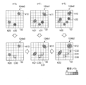
- the ambient light / sound storage unit 125 stores the ambient sound data (for example, FIG. 9) obtained by the sound source registration / update processing (see FIG. 9) and the noise level registration processing at the observation position (see FIG. 10). 8 using the environmental sound data 124b2) at the lower right and the transfer function map 127a input from the transfer function storage unit 127, an ambient light / sound map in which the noise level is set up to an unobserved point (grid). 125a is created.
- the ambient light / sound storage unit 125 firstly stores the acoustic model of the sound source at the position K22 at the observation position c30.
- An inverse calculation is specified based on the transfer function map 127a from the noise level of the grid C30. More specifically, the ambient light / sound storage unit 125 sequentially stores the noise level set in the grid C30 in the transfer function map 127a on the grids located on the path from the grid C30 to the grid corresponding to the position K22. Back-propagation based on As a result, the acoustic model of the sound source at the position K22 is back calculated from the noise level of the grid C30.
- the ambient light / sound storage unit 125 sequentially propagates the acoustic model of the sound source at the position K22 to grids other than the grids C30 to C32 based on the transfer function map 127a with the grid at the position K22 as a starting point. Estimate and set the noise level for all grids for which no direct noise level is observed. As a result, an ambient light / sound map 125a in which noise levels are set for all grids as shown in the right diagram of FIG. 11 is created. When the noise level transmitted from a plurality of routes is obtained for one grid, for example, the highest noise level may be set as the noise level of the grid.
- the ambient light / sound storage unit 125 determines whether or not the sound source data is included in the ambient light / sound information 124a (step S121). This operation ends (NO in step S121). On the other hand, if the sound source data is included (YES in step S121), the ambient light / sound storage unit 125 proceeds to step S122, and performs processing for all the sound source data included in the ambient light / sound information 124a. The processing of is performed.
- step S122 the environment light / sound storage unit 125 specifies a grid on the grid map G32 corresponding to the position of the sound source indicated by each sound source data for all the sound source data included in the environment light / sound information 124a.
- the ambient light / sound storage unit 125 initializes a list for registering grids to be processed (hereinafter, referred to as a first processing schedule list) (step S123), and specifies the first processing schedule list in step S122.
- the grids of all the sound sources obtained are additionally registered as grids to be processed (step S124).
- the ambient light / sound storage unit 125 determines whether or not the first processing schedule list is empty (step S125). If the first processing schedule list is empty, that is, if the processing schedule grid is 1 in the first processing schedule list. If none has been registered (YES in step S125), this operation ends. On the other hand, if the processing schedule grid is registered in the first processing schedule list (NO in step S125), the ambient light / sound storage unit 125 stores one of the processing schedule grids registered in the first processing schedule list. It is selected as the grid of interest (step S126), and the selected processing schedule grid is deleted from the first processing schedule list (step S127).
- step S1208 the environment light / sound storage unit 125 proceeds to step S128, and executes the subsequent processing for all the adjacent grids adjacent to the grid of interest (this is referred to as a first adjacent grid).
- the rule for selecting the grid to be processed in step S126 may be various rules such as round robin.
- step S1208 the ambient light / sound storage unit 125 specifies the transfer function between the grid of interest and each of the first adjacent grids adjacent thereto based on the transfer function map 127a input from the transfer function storage unit 127. I do. Subsequently, the ambient light / sound storage unit 125 obtains the noise level of each first adjacent grid using the transfer function from the noise level actually measured for each of the first adjacent grids and the noise level of the grid of interest. The noise level is set to the larger one of the noise levels (step S129). In step S129, for the first adjacent grid for which the actually measured noise level has not been set, the noise level determined using the transfer function from the noise level of the grid of interest is set.
- the ambient light / sound storage unit 125 has already performed the processing of setting the noise level for the grids adjacent to all the first adjacent grids adjacent to the grid of interest (this is referred to as a second adjacent grid). It is determined whether or not there is (Step S130), and if the execution has been completed (YES in Step S130), the process returns to Step S125 to execute the subsequent operations. On the other hand, when there is an unprocessed second adjacent grid (NO in step S130), the ambient light / sound storage unit 125 adds the unprocessed second adjacent grid to the first process schedule list as a process schedule grid ( (Step S131) Then, the process returns to step S125 to execute the subsequent operations.
- the transfer function is a function expressing the attenuation rate in each frequency band of the sound when the sound is transmitted from a certain point (corresponding to the grid) to another point (corresponding to the grid).
- the transfer function can be defined as information indicating how easily the risk is transmitted in the space.
- the operation of the transfer function estimating unit 126 includes, for example, a transfer function estimating operation of estimating a transfer function using the measurement data 101a acquired by the sensor 101 and creating the first transfer function information 126b; A noise level interpolation operation for generating the second transfer function information 126c by interpolating the noise level using the environmental sound data input from the ambient light / sound storage unit 125 may be included.
- the transfer function information 126a described above includes first transfer function information 126b and second transfer function information 126c.
- the transfer function estimation operation estimates a transfer function between each point (grid) in a predetermined area in consideration of an object recognized in an object detection process for the measurement data 101a. Operation.
- An example of the transfer function estimating operation will be described with reference to FIG. As illustrated in FIG. 13, in the transfer function estimation operation, for example, by performing object detection on the measurement data 101a, an object constituting the environment such as the wall W10 is detected, and its position and layout are specified.
- the object to be detected may include a window glass, a curtain, a sofa, and the like, in addition to the wall W10.
- the shape, material, and the like of the detected object are estimated, and the attenuation rate for each object is specified from the estimated object shape, material, and the like.
- the shape, the material, and the like of the wall W10 are estimated, and the attenuation rate of the wall W10 is specified from the estimated shape, the material, and the like.
- a transfer function between each point in a predetermined area is estimated from the specified layout of the object and the attenuation rate of each object.
- the first transfer function information 126b indicating the attenuation rate at each point (grid) as shown on the right side of FIG. 13 is created. Note that, in addition to the attenuation rate, a reflectance or the like may be specified and included in the first transfer function information 126b.
- the noise level interpolation operation is an operation of interpolating the noise level at each point (grid) in a predetermined area based on the position of the sound source and the noise level included in the environmental sound data. It is.
- An example of the noise level interpolation operation will be described with reference to FIG. FIG. 14 illustrates a case where the environmental sound data 124b2 shown in the lower right of FIG. 8 is used.
- the noise level interpolation operation is based on, for example, the sound source positions K12 and K22 included in the environmental sound data 124b2 and the noise levels on the grids C30 to C32 corresponding to the observation positions c30 to c32. Then, the transfer function between points is directly estimated.
- the sound propagated from the sound source located at the position K22 to the grid C31 of the observation position c31. Further propagates to the grid C32 at the observation position c32 via a route via the adjacent grid C303, a route via the adjacent grid C304, and a direct route in an oblique direction. Therefore, the noise level of each of the adjacent grids C303 and C304 can be directly obtained from the difference between the noise level of the grid C31 at the observation position c31 and the noise level of the grid C32 at the observation position c32.
- the noise level between the noise level of the grid C31 at the observation position c31 and the noise level of the grid C32 at the observation position c32 can be determined to be the noise levels of the adjacent grids 303 and C304, respectively.
- the noise levels of the grids C30 and C302 adjacent to the grid C30 corresponding to the observation position c30 and the grid C31 corresponding to the observation position c31 can be directly obtained.
- the second transfer function information 126c in which the noise level of the grid sandwiched by the grids whose noise levels have already been set is interpolated is created.
- the transfer function estimating unit 126 first determines whether or not there is a grid in which the noise level is set in the environmental sound data input from the ambient light / sound storage unit 125. It is determined (step S141). If there is no grid for which the noise level has been set (NO in step S141), the transfer function estimating unit 126 ends this operation.
- the transfer function estimating unit 126 subsequently determines whether or not the sound source is included in the environmental sound data (step S142). If no sound source is included (NO in step S142), the transfer function estimating unit 126 ends this operation. On the other hand, if the sound source is included (YES in step S142), the transfer function estimating unit 126 proceeds to step S143, and performs the subsequent operation on all combinations of the sound source and the grid for which the noise level is set. Execute.
- step S143 the transfer function estimating unit 126 specifies the shortest path connecting the grid for which the noise level is set and the grid corresponding to the position of the sound source. Subsequently, the transfer function estimating unit 126 determines whether there is another grid on which the noise level is set on the specified shortest path (Step S144). If there is no other grid (NO in step S144), the transfer function estimating unit 126 ends this operation. On the other hand, if another grid exists (YES in step S144), the transfer function estimating unit 126 determines the noise level of each of the grids located between the two grids on which the noise level is set on the shortest path by the noise level.
- step S145 This operation is determined based on the difference between the noise levels of the two grids for which the levels are set and the distance from the sound source along the shortest path of each of the two grids for which the noise levels are set (step S145). finish.
- step S145 for example, the position and the noise level on the shortest path of the grid on which the noise level closer to the sound source is set, and the position and the noise level on the shortest path of the grid on which the noise level is set farther from the sound source From the noise level, the slope of a function indicating the amount of increase or decrease of the noise level with respect to the change in the position on the shortest path is obtained, and based on this slope, the noise level is sandwiched between two grids on which the noise level is set on the shortest path. Other grid noise levels are required.
- the transfer function storage unit 127 creates the transfer function map 127a by integrating the first transfer function information 126b and the second transfer function information 126c created by the transfer function estimation unit 126.
- FIG. 16 shows a flow of processing for integrating the first transfer function information 126b and the second transfer function information 126c.
- the transfer function storage unit 127 sets the grids C30 to C32 and the adjacent grids C301 to C304 for which the noise levels are set in the second transfer function information 126c, in the first transfer function information 126b.
- the first transfer function information 126b and the second transfer function information 126c are integrated by overwriting the damping rate or the like with the noise level set in the second transfer function information 126c. Thereby, a transfer function map 127a shown on the right side of FIG. 16 is created.
- the action planning map creator 104 uses the influence target map 123a, the ambient light / sound map 125a, and the transfer function map 127a created as described above as inputs to plan an action to be executed by the autonomous mobile unit 1.
- An action plan map 104a to be used is created.
- costs are used according to the presence or absence of obstacles and the distance to obstacles.
- the effect of the sound generated by the autonomous mobile unit 1 on the affected object is used as the cost.
- the cost is determined in accordance with the degree to which the influence target is concerned about the YdB sound, and the action plan of the autonomous mobile 1 is made using the cost.
- an allowable volume for setting the influence on the influence target existing in the predetermined area to be equal to or less than an allowable value A map is created.
- the permissible sound volume map shows that the permissible sound volume at which the effect of the target within the predetermined area is less than or equal to the permissible value even if the autonomous mobile object 1 emits a sound at each point, that is, the autonomous mobile object 1 at each point.
- the maximum value of the sound that is permitted to emit is registered.
- FIG. 17 shows an example of a process when the action plan map creating unit 104 creates an allowable volume map. In the example shown in FIG.
- the action plan map creator 104 acquires information such as the positions P12 and P22 of the influence target and the estimated sensitivity of the influence target from the influence target map 123a2, and obtains the influence from the ambient light / sound map 125a.
- the permissible sound volume in the grids corresponding to the target positions P12 and P22 is estimated, and this permissible sound volume is arranged on the grid map G32.
- a position allowable volume map 104b is created.
- the estimation of the permissible sound volume in the grid corresponding to the position of the influence target is performed, for example, as follows: "Since the noise level has already reached XdB at the position of the influence target, the influence target does not care about sounds below Xdb.”
- Such a rule can be realized by previously implementing a rule for estimating the allowable volume for each of the influence targets as a function.
- the action plan map creator 104 uses the inverse function of the transfer function obtained from the transfer function map 127a to calculate the permissible volume estimated for the grids corresponding to the affected positions P12 and P22 as a whole.
- the grid For example, when it is specified from the transfer function map 127a that a certain frequency band is attenuated by YdB when transmitting to an adjacent grid, it is far from the grid closer to the grid corresponding to the position of the influence target.
- the allowable volume is propagated to the grid on the side, the inverse function of setting the allowable volume obtained by increasing the allowable volume of the grid on the near side by YdB to the grid on the far side is used, so that the positions P12 and P22 to be affected are used. Is propagated to the entire grid.
- an allowable volume map 104c in which the maximum value of the sound permitted to be emitted by the autonomous mobile body 1 at each point is registered.
- the created permissible volume map 104c is output to the action planning unit 105 together with the map for calculating the cost according to the presence or absence of the obstacle or the distance to the obstacle or as the action planning map 104a alone. You.
- the action plan map creating unit 104 first determines whether or not an influence target exists in a predetermined area based on the influence target map 123a (step S151). When the influence target does not exist (NO in step S151), the action plan map creating unit 104 ends the operation. On the other hand, when the influence target exists (YES in step S151), the action plan map creating unit 104 proceeds to step S152, and performs the subsequent operation on all the influence targets included in the influence target map 123a. I do.
- step S152 the action plan map creating unit 104 specifies grids corresponding to all the positions of the influence targets included in the influence target map 123a.
- the action plan map creating unit 104 acquires the noise level of the specified grid by referring to the ambient light / sound map 125a (step S153).
- the action plan map creator 104 obtains the permissible volume of the specified grid by using a function implemented in advance for estimating the permissible volume for each affected object (step S154). For example, the action plan map creating unit 104 substitutes the estimated sensitivity of the influence target acquired from the influence target map 123a and the noise level of the specified grid into a function implemented in advance, thereby allowing the specified grid to accept the specified grid. Find the volume.
- the action plan map creation unit 104 initializes a list for registering a grid to be processed (hereinafter, referred to as a second processing schedule list) (step S155), and specifies the second processing schedule list in step S152. Grids corresponding to all the affected positions are additionally registered as scheduled grids (step S156).
- the action plan map creating unit 104 determines whether or not the second processing schedule list is empty (step S157). If the second processing schedule list is empty, that is, if the processing schedule grid is 1 in the second processing schedule list. If none has been registered (YES in step S157), this operation ends. On the other hand, when the processing schedule grid is registered in the second processing schedule list (NO in step S157), the action plan map creating unit 104 stores one of the processing schedule grids registered in the second processing schedule list. It is selected as the grid of interest (step S158), and the selected processing schedule grid is deleted from the second processing schedule list (step S159).
- step S160 the action plan map creating unit 104 proceeds to step S160, and executes the subsequent processing on all the adjacent grids adjacent to the grid of interest (this is referred to as a third adjacent grid).
- the rule for selecting the grid to be processed in step S158 may be various rules such as round robin.
- step S160 the action plan map creator 104 specifies the transfer function between the grid of interest and each of the third adjacent grids adjacent thereto based on the transfer function map 127a input from the transfer function storage 127. I do. Subsequently, the action plan map creator 104 calculates the allowable volume of each third adjacent grid by using the allowable volume obtained in step S154 for each of the third adjacent grids and the inverse function of the transfer function from the allowable volume of the grid of interest. It is set to the higher allowable volume of the allowable volume obtained by using (step S162). In step S162, for the third adjacent grid for which the allowable volume has not been determined in step S154, the allowable volume determined using the inverse function of the transfer function from the allowable volume of the grid of interest is set.
- the action plan map creating unit 104 has already performed the processing of setting the allowable volume for the grids adjacent to all the third adjacent grids adjacent to the grid of interest (this is referred to as a fourth adjacent grid). It is determined whether or not there is (Step S163), and if the execution has been completed (YES in Step S163), the process returns to Step S157 to execute the subsequent operations. On the other hand, when there is an unprocessed fourth adjacent grid (NO in step S163), the action plan map creating unit 104 adds the unprocessed fourth adjacent grid to the second process schedule list as a process schedule grid ( (Step S164) Then, the process returns to step S157 to execute the subsequent operations.
- the action planning unit 105 makes an action plan of the autonomous mobile unit 1 using the action planning map 104a including the allowable volume map 104c created as described above. At this time, for example, the action of the autonomous mobile body 1 at each point is planned based on the allowable volume at each point registered in the allowable volume map 104c. For example, when the noise generated by the autonomous mobile body 1 is larger as the speed is higher, the action planning unit 105 determines the autonomous mobile body at each point based on the allowable volume of each point registered in the allowable volume map 104c. 1 is determined. In addition, the behavior planning unit 105 limits an area in which the autonomous mobile 1 can pass, based on the sound emitted by the autonomous mobile 1.
- FIG. 19 is a block diagram illustrating a schematic configuration example of the autonomous system 100 according to the present embodiment.
- an autonomous system 100 according to the present embodiment has a configuration in which one or more autonomous mobile objects 1A to 1N are connected to a server 2 via a network 3.
- a server 2 via a network 3.
- the storage unit 123, the ambient light / sound recognition unit 124, the ambient light / sound storage unit 125, the transfer function estimation unit 126, and the transfer function storage unit 127 may be arranged on the server 2 side.
- the server 2 may be a server group including a plurality of servers, such as a cloud server.
- the action plan map creator 104 When the action plan map creator 104 is arranged on the server 2 side, the action plan map creator 104 includes the optical / acoustic sensor 121 and the sensor mounted on each of the one or more autonomous mobile bodies 1.
- One or more autonomous mobile objects existing in the same area are integrated by integrating the affected object map 123a, the ambient light / sound map 125a, and the transfer function map 127a generated from the light / acoustic data 121a and the measurement data 101a acquired in 101.
- a common action plan map may be created. This makes it possible to create the action plan map 104a using more information, and thus to create a more accurate action plan map 104a.
- FIG. 20 is a block diagram illustrating a schematic configuration example of the autonomous mobile body according to the present embodiment.
- the autonomous mobile body 1 includes, for example, a CPU (Central Processing Unit) 12, a DRAM (Dynamic Random Access Memory) 13, a flash ROM (Read Only Memory) 14, and a PC (Personal Computer) card interface (I).
- / F) 15, a control unit 10 formed by connecting the wireless communication unit 16 and the signal processing circuit 11 to each other via an internal bus 17, and a battery 18 as a power source of the autonomous mobile unit 1.
- the control unit 10 corresponds to, for example, the control unit 106 described above.
- the autonomous mobile body 1 has a movable part 26 such as a joint part of an arm and a leg, a wheel or a caterpillar, and an operating mechanism for realizing an operation such as movement and gesture, and a drive part for driving the movable part. And an actuator 107.
- the autonomous mobile body 1 serves as a sensor for acquiring information such as a moving distance, a moving speed, a moving direction, and a posture (hereinafter, referred to as an inner field sensor) for detecting the direction and the acceleration of the own machine.
- An inertial measurement device (Inertial ⁇ Measurement ⁇ Unit: IMU) 20 and an encoder (or potentiometer) 28 for detecting a driving amount of the actuator 107 are provided.
- an acceleration sensor, an angular velocity sensor, or the like can be used as the inner field sensor.
- the autonomous mobile body 1 captures an external situation as a sensor (hereinafter, referred to as an external sensor) that acquires information such as the terrain around the own device and the distance and direction to an object existing around the own device.
- an external sensor that acquires information such as the terrain around the own device and the distance and direction to an object existing around the own device.
- ToF Time of Flight
- LIDAR Light Detection and Ranging or Laser Imaging and Detection and Ranging
- GPS Global Positioning System
- magnetic sensor magnetic sensor
- Bluetooth registered trademark
- Wi-Fi Wi-Fi
- a measurement unit hereinafter, referred to as a radio field intensity sensor of the radio field intensity in the wireless communication unit 16 such as a trademark may be used.
- the autonomous mobile body 1 includes a microphone 23 as the optical / acoustic sensor 121 for collecting an external sound.
- the above-described CCD camera 19 may be used not only as an external sensor but also as one of the optical / acoustic sensors 121.
- the invention is not limited thereto, and a separate optical sensor may be provided as the optical / acoustic sensor 121.
- the autonomous mobile body 1 also includes a touch sensor 22 for detecting a physical pressure received from the outside, a speaker 24 for outputting sound and the like to the surroundings, and various information to a user or the like.
- a display unit 25 for displaying may be provided.
- various sensors such as the IMU 20, the touch sensor 22, the ToF sensor 21, the microphone 23, the speaker 24, and the encoder (or potentiometer) 28, the display unit, the actuator 107, the CCD camera (hereinafter simply referred to as a camera) 19, and the battery Reference numerals 18 are connected to the signal processing circuit 11 of the control unit 10, respectively.
- the signal processing circuit 14 sequentially captures sensor data, image data, and audio data supplied from the various sensors described above, and sequentially stores them at predetermined positions in the DRAM 13 via the internal bus 17.
- the signal processing circuit 11 sequentially takes in remaining battery power data indicating the remaining battery power supplied from the battery 18 and stores the data in a predetermined position in the DRAM 13.
- the sensor data, image data, audio data, and remaining battery data stored in the DRAM 13 in this manner are used when the CPU 12 controls the operation of the autonomous mobile unit 1 and, if necessary, communicate with the wireless communication.
- the data is transmitted to the external server 2 via the unit 16.
- the influence target information 122a, the influence target map 123a, the ambient light / sound information 124a, the ambient light / sound map 125a, the transfer function information 126a, the transfer function map 127a, the outside world information 102a, the outside world map 103a, the action plan map 104a, and the like. May be transmitted to the external server 2 via the wireless communication unit 16 as necessary.
- the wireless communication unit 16 communicates with the external server 2 via a predetermined network such as a wireless LAN (Local Area Network) or a mobile communication network in addition to Bluetooth (registered trademark) and Wi-Fi (registered trademark). It may be a communication unit for performing communication.
- a predetermined network such as a wireless LAN (Local Area Network) or a mobile communication network in addition to Bluetooth (registered trademark) and Wi-Fi (registered trademark). It may be a communication unit for performing communication.
- the CPU 12 transmits the control program stored in the memory card 30 or the flash ROM 14 loaded in the PC card slot (not shown) via the PC card interface 15 or directly. Read and store this in the DRAM 13.
- the CPU 12 based on the sensor data, image data, audio data, and remaining battery power data sequentially stored in the DRAM 13 from the signal processing circuit 11 as described above, the status of its own device and the surroundings, and instructions from the user. Judge whether there is any action or not.
- the CPU 12 performs self-position estimation and various operations using map data stored in the DRAM 13 or the like or map data acquired from the external server 2 via the wireless communication unit 16 and various information. .
- the CPU 12 generates a control command 106 a to be given to the actuator 107 based on the action plan information (own device) 105 a acquired from the external server 2 via the wireless communication unit 16, and sends the control command 106 a via the signal processing circuit 11. To the actuator 107.
- the CPU 12 determines the subsequent action based on the above-described determination result, the estimated own position, the control program stored in the DRAM 13, the created or received action plan information (own device) 105a, and the like. By driving the necessary actuator 107 based on the determination result, various actions such as movement and gesture are executed.
- the CPU 12 generates audio data as necessary, and supplies the generated audio data to the speaker 24 as an audio signal via the signal processing circuit 11 so that the audio based on the audio signal is output to the outside, or the display unit 25 To display various information.
- the autonomous mobile body 1 is configured to be able to act autonomously according to its own device and surrounding conditions, and instructions and actions from the user.
- the configuration of the autonomous mobile 1 described above is merely an example, and various autonomous mobiles can be applied according to purposes and applications. That is, the autonomous mobile object 1 according to the present disclosure is not limited to an autonomous mobile robot such as a domestic pet robot, a robot cleaner, an unmanned aerial vehicle, a following transport robot, and the like, but may include various mobile objects such as a car that estimates its own position. It is possible to apply.
- an autonomous mobile robot such as a domestic pet robot, a robot cleaner, an unmanned aerial vehicle, a following transport robot, and the like
- various mobile objects such as a car that estimates its own position. It is possible to apply.
- the present embodiment it is possible to estimate the influence on the surrounding influence target due to the risk generated by the autonomous mobile body 1.
- the autonomous mobile object 1 before the autonomous mobile object 1 takes an action, it is possible to estimate the influence on the surrounding influence target due to the action of the autonomous mobile object 1, so that the surrounding It is possible to make an action plan in which the influence on the affected object is suppressed in advance. For example, it is possible to plan an action in which the influence of the risk of the autonomous mobile body 1 on the surrounding influence target is suppressed to an allowable value or less.
- the autonomous system 100 that is easily accepted by an environment that is easily affected by risks such as people, for example, an environment such as a library or an office.
- the autonomous mobile body 1 can be controlled in an autonomous manner so that the risk generated by the autonomous mobile body 1 is not more than an allowable amount according to the surrounding environment. It is also possible to make an action plan for the mobile unit 1. Further, the present invention is not limited to the case where the autonomous mobile body 1 affects the surrounding influence target, but may be a case where it is desired to positively influence the surrounding such as a warning sound or a projection. According to the autonomous system 100 according to the present embodiment, even in such a case, by estimating the amount of influence on the target to be affected, it is possible to appropriately adjust the degree of the risk generated by the autonomous mobile body 1. Will be possible.
- An information processing apparatus comprising: a planning unit configured to plan an action to be performed by a driving unit based on an influence target affected by a risk of propagating in a space existing in a predetermined area.
- the apparatus further includes a creating unit that creates an affected map including information on the affected object in the predetermined area, The information processing device according to (1), wherein the planning unit plans the action performed by the driving unit based on the influence target map.
- a recognition unit that determines a position of the affected object in the predetermined area based on the sensor information acquired by the predetermined sensor, The creating unit creates the influence target map including information on an area where the influence target may exist, based on the position of the influence target in the predetermined area determined by the recognition unit.
- the information processing device wherein the planning unit plans the action to be executed by the driving unit based on information on a region in which the influence target may exist, which is included in the influence target map. .
- the recognition unit based on the sensor information, further determines the degree of influence that the affected target receives from the risk, The creating unit creates the influence target map including the degree of the influence determined by the recognition unit, The planning unit plans the action to be executed by the driving unit based on the degree of the influence included in the influence target map, in addition to the information on the area where the influence target may exist.
- the information processing device according to (1).
- a recognition unit that determines the degree of risk observed at each point in the predetermined area, and the position of the source of the risk in the predetermined area. Further comprising The creating unit, based on the degree of the risk observed at each point in the predetermined area determined by the recognition unit and the position of the source of the risk in the predetermined area, the environmental map make, The planning unit is executed by the driving unit based on information on the degree of the risk caused by the risk source other than the driving unit at each point in the predetermined area included in the environment map.
- the information processing apparatus according to (5), wherein the action is planned.
- the creating unit propagates the degree of the risk observed at each point in the predetermined area to a position in the predetermined area of the source of the risk based on an inverse function of a predetermined transfer function.
- the predetermined area Based on the sensor information obtained by the predetermined sensor, the position and the attenuation rate of the object existing in the predetermined area are specified, and based on the specified position and the attenuation rate of the object, the predetermined area Further comprising an estimator for determining the attenuation rate at each point in the,
- the information processing device according to (8), wherein the creation unit creates the transfer function map based on the attenuation rate at each point in the predetermined area determined by the estimation unit.
- the apparatus further includes an estimation unit that interpolates the degree of risk at a point where the degree of risk is not observed in a predetermined area, The creation unit, the degree of the risk observed at each point in the predetermined area, and the degree at the point where the degree of the risk in the predetermined area interpolated by the estimation unit is not observed.
- the information processing device according to (8), wherein the transfer function map is created based on a degree of risk.
- the estimating unit calculates the degree of the risk at the point where the degree of the risk in the predetermined area is not observed, the position of the source of the risk in the predetermined area and the degree of the risk.
- the information processing apparatus according to (10), wherein the information is calculated based on a positional relationship with the observed point.
- a first creating unit that creates an affected map including information on the affected object in the predetermined area
- a second creating unit that creates an environmental map including information on a degree of risk caused by the risk source other than the driving unit in the predetermined area
- a third creation unit that creates a transfer function map including information on a transfer function indicating the ease of transmission of the risk in the space in the predetermined area
- the planning unit plans the action performed by the driving unit based on the influence target map, the environment map, and the transfer function map.
- a fourth creation unit that creates a map related to a degree of risk that is allowed to occur to the driving unit based on the influence target map, the environment map, and the transfer function map, The information processing device according to (12), wherein the planning unit plans the action to be performed by the driving unit based on a map relating to the degree of the allowable risk.
- the information processing apparatus according to any one of (1) to (13), wherein the risk is at least one of sound, light, wind, and odor.
- the risk is sound
- the information processing apparatus according to any one of (1) to (13), wherein the influence target is an influence target affected by sound.
- the information processing apparatus according to any one of (1) to (15), wherein the driving unit is a driving unit mounted on an autonomous mobile body having a mechanism that moves autonomously.
- the information processing apparatus according to any one of (1) to (15), further including the driving unit that executes an action involving occurrence of the risk.
- An autonomous mobile body having a drive unit for performing an action involving occurrence of a risk of propagating in space;
- a planning unit configured to plan an action to be executed by the driving unit based on an influence target affected by the risk existing in a predetermined area, the communication unit being communicably connected to the autonomous mobile body via a predetermined network.
- An information processing system comprising: (19) An action planning method including a step of planning an action to be executed by a driving unit based on an influence target affected by a risk of propagating in a space existing in a predetermined area. (20) A program for causing a computer to execute a step of planning an action to be executed by a drive unit based on an affected object affected by a risk of propagating in a space existing in a predetermined area. (21)
- the driving unit is a driving unit mounted on a domestic pet robot, a robot cleaner, an unmanned aerial vehicle, a following and carrying robot, an automobile equipped with an automatic driving function, a robot arm, or a smart speaker. 17) The information processing apparatus according to any one of the above items 17).
Abstract
The present invention reduces the risk that sound or light emitted from a device will have an influence on the surroundings. An information processing device (100) according to an embodiment of the present invention is provided with a planning unit (105) that plans an action to be executed by a driving unit (107), on the basis of an influence object that is under the influence of a risk propagating through a space existing in a prescribed area.
Description
本開示は、情報処理装置、情報処理システム、行動計画方法及びプログラムに関する。
The present disclosure relates to an information processing device, an information processing system, an action planning method, and a program.
近年、家庭におけるロボット掃除機やペットロボット、工場や物流倉庫における運搬ロボットなど、人工知能を備えた自律移動ロボットの開発が盛んに行なわれている。
In recent years, autonomous mobile robots equipped with artificial intelligence, such as robot cleaners and pet robots at home and transport robots at factories and distribution warehouses, have been actively developed.
一般的に、自律移動ロボットの行動計画では、2次元の行列データである格子地図(オキュパンシーマップ、オキュパンシーグリッドマップ、又は、単にグリッドマップともいう)を用いて、自律移動ロボットの移動経路などがスケジューリングされる。
In general, an action plan of an autonomous mobile robot uses a grid map (occupancy map, occupancy grid map, or simply a grid map), which is two-dimensional matrix data, to move the autonomous mobile robot. Is scheduled.
自律移動ロボットの移動経路を決定する際の経路探索では、自律移動ロボットと障害物との衝突を避けるために、自律移動ロボットから障害物までの距離がコストとして用いられる。具体的には、センサ等により障害物の存在が観測された位置に対応する格子地図上のマスに対して障害物の存在確率が高く設定され、障害物が存在しないことが観測されたマスに対して障害物の存在確率が低く設定される。そして、この格子地図に対し、自律移動ロボットの機体サイズや安全率等を表現するために、障害物領域の膨張処理等が実行され、その後、ダイクストラ法やA*(スター)に代表されるグラフ探索アルゴリズムを用いて最適経路が決定される。
経 路 In the route search when determining the movement route of the autonomous mobile robot, the distance from the autonomous mobile robot to the obstacle is used as a cost to avoid collision between the autonomous mobile robot and the obstacle. Specifically, the existence probability of the obstacle is set higher than the mass on the grid map corresponding to the position where the presence of the obstacle is observed by the sensor or the like. On the other hand, the existence probability of the obstacle is set low. Then, in order to express the body size, the safety factor, and the like of the autonomous mobile robot, the expansion processing of the obstacle area is performed on the grid map, and thereafter, a graph represented by the Dijkstra method or A * (star) is performed. An optimal route is determined using a search algorithm.
しかしながら、通常の自律移動ロボットは、目的地への移動やアーム等を使った各種作業やユーザとのコミュニケーション等を行なうために、モータの駆動音や音声や光等を発している。そのため、経路探索では、障害物との衝突といったような有形のリスクから自機が影響を受けることを回避するだけでなく、自身が発した音や光等のリスクによって周囲が受ける影響を低減するように、最適経路を探索する必要がある。
However, a normal autonomous mobile robot emits a motor driving sound, voice, light, or the like in order to move to a destination, perform various operations using an arm, or communicate with a user. For this reason, route search not only prevents the aircraft from being affected by tangible risks such as collisions with obstacles, but also reduces the impact on the surroundings due to risks such as sound and light emitted by itself. Thus, it is necessary to search for the optimal route.
そこで本開示では、自機が発した音や光等のリスクによって周囲が受ける影響を低減することが可能な情報処理装置、情報処理システム、行動計画方法及びプログラムを提案する。
Therefore, the present disclosure proposes an information processing device, an information processing system, an action planning method, and a program that can reduce the influence on the surroundings due to the risk of sound, light, or the like emitted by the own device.
上記の課題を解決するために、本開示に係る一形態の情報処理装置は、所定のエリア内に存在する空間中を伝播するリスクによって影響を受ける影響対象に基づいて駆動部が実行する行動を計画する計画部を備える。
In order to solve the above-described problems, an information processing apparatus according to an embodiment of the present disclosure includes an action performed by a driving unit based on an influence target that is affected by a risk of propagating in a space existing in a predetermined area. It has a planning department to plan.
(作用)本開示に係る一形態の情報処理装置によれば、駆動部が発するリスクによって周囲の影響対象が受ける影響が抑えられるように、駆動部の行動計画を事前に立てることが可能となる。これにより、自機が発した音や光等のリスクによって周囲が受ける影響を低減することが可能となる。
(Operation) According to an information processing apparatus according to an embodiment of the present disclosure, an action plan of a driving unit can be set in advance so that a risk generated by the driving unit can suppress the influence on surrounding influence targets. . As a result, it is possible to reduce the influence on the surroundings due to the risk of sound or light emitted by the own device.
本開示によれば、自機が発した音や光等のリスクによって周囲が受ける影響を低減することが可能な情報処理装置、情報処理システム、行動計画方法及びプログラムを実現することが可能となる。なお、ここに記載された効果は必ずしも限定されるものではなく、本開示中に記載された何れかの効果であってもよい。
According to the present disclosure, it is possible to realize an information processing device, an information processing system, an action planning method, and a program that can reduce the influence on the surroundings due to the risk of sound, light, or the like emitted by the own device. . Note that the effects described here are not necessarily limited, and may be any of the effects described in the present disclosure.
以下に、本開示の一実施形態に係る情報処理装置、情報処理システム、行動計画方法及びプログラムについて、図面に基づいて詳細に説明する。なお、以下の実施形態において、同一の部位には同一の符号を付することにより重複する説明を省略する。
Hereinafter, an information processing device, an information processing system, an action planning method, and a program according to an embodiment of the present disclosure will be described in detail with reference to the drawings. In the following embodiments, the same portions will be denoted by the same reference characters, without redundant description.
また、以下に示す項目順序に従って本開示を説明する。
1.一実施形態
1.1 自律システムの概要
1.2 自律システムの構成例
1.3 自律システムの動作例
1.3.1 影響対象認識部の動作例
1.3.2 影響対象記憶部の動作例
1.3.3 環境光/音認識部の動作例
1.3.4 環境光/音記憶部の動作例
1.3.4.1 音源登録/更新処理
1.3.4.2 観測位置での騒音レベル登録処理
1.3.4.3 騒音レベル推定動作
1.3.4.3.1 騒音レベル推定動作のフローチャート
1.3.5 伝達関数推定部の動作例
1.3.5.1 伝達関数推定動作の例
1.3.5.2 騒音レベル補間動作の例
1.3.5.2.1 騒音レベル補間動作のフローチャート
1.3.6 伝達関数記憶部の動作例
1.3.7 行動計画用地図作成部の動作例
1.3.7.1 許容音量地図作成動作のフローチャート
1.3.8 行動計画用地図作成部の動作例
1.4 システム構成例
1.5 自律移動体
1.6 むすび In addition, the present disclosure will be described according to the following item order.
1. 1. Embodiment 1.1 Overview of Autonomous System 1.2 Configuration Example of Autonomous System 1.3 Operation Example of Autonomous System 1.3.1 Operation Example of Impact Target Recognition Unit 1.3.2 Operation Example of Impact Target Storage Unit 1.3.3 Operation example of ambient light / sound recognition unit 1.3.4 Operation example of ambient light / sound storage unit 1.3.4.1 Sound source registration / update processing 1.3.4.2 At observation position 1.3.4.3 Noise level estimation operation 1.3.3.4 Noise level estimation operation flowchart 1.3.5 Operation example of transfer function estimating section 1.3.5.1 Example of transfer function estimation operation 1.3.5.2 Example of noise level interpolation operation 1.3.3.52 Flow chart of noise level interpolation operation 1.3.6 Operation example of transfer function storage section 1.3. 7 Operation example of the action planning map creator .3.7.1 allowable volume operation example 1.4 System Configuration 1.5 autonomous moving body 1.6 knot flowchart 1.3.8 action plan for mapping of the mapping operation
1.一実施形態
以下で例示する実施形態では、家庭内ペットロボットやロボット掃除機や無人航空機や追従運搬ロボットや自動運転機能を搭載した自動車など、各種センサを搭載した自律移動体(以下、自機ともいう)を含む自律システムが適用対象として想定されているが、本開示はこのような自律システムに限定されず、例えば駆動機構を備えたロボットアームやマニピュレータ等の可動部及び/又はインタラクティブなコミュニケーション機能を備えたスマートスピーカなど、自律又は遠隔操作による駆動(発音や発光等を含む)によって音を発する可能性のある種々の装置又はシステムを適用対象とすることが可能である。 1. One Embodiment In an embodiment exemplified below, an autonomous mobile body (hereinafter referred to as own machine) equipped with various sensors, such as a domestic pet robot, a robot cleaner, an unmanned aerial vehicle, a following transport robot, and an automobile equipped with an automatic driving function. The present disclosure is not limited to such an autonomous system, but includes a movable unit such as a robot arm or manipulator having a drive mechanism and / or an interactive communication function. It is possible to apply various devices or systems that may emit sound by autonomous or remote control driving (including sound generation, light emission, and the like), such as a smart speaker equipped with.
以下で例示する実施形態では、家庭内ペットロボットやロボット掃除機や無人航空機や追従運搬ロボットや自動運転機能を搭載した自動車など、各種センサを搭載した自律移動体(以下、自機ともいう)を含む自律システムが適用対象として想定されているが、本開示はこのような自律システムに限定されず、例えば駆動機構を備えたロボットアームやマニピュレータ等の可動部及び/又はインタラクティブなコミュニケーション機能を備えたスマートスピーカなど、自律又は遠隔操作による駆動(発音や発光等を含む)によって音を発する可能性のある種々の装置又はシステムを適用対象とすることが可能である。 1. One Embodiment In an embodiment exemplified below, an autonomous mobile body (hereinafter referred to as own machine) equipped with various sensors, such as a domestic pet robot, a robot cleaner, an unmanned aerial vehicle, a following transport robot, and an automobile equipped with an automatic driving function. The present disclosure is not limited to such an autonomous system, but includes a movable unit such as a robot arm or manipulator having a drive mechanism and / or an interactive communication function. It is possible to apply various devices or systems that may emit sound by autonomous or remote control driving (including sound generation, light emission, and the like), such as a smart speaker equipped with.
以下で例示する実施形態では、自律移動体が行動計画を立てる際に、自律移動体1が発する音や光や風や匂い等の空間中を伝播するリスクが周囲に与える影響が考慮される。それにより、自律移動体1が環境に与える悪影響を低減するように行動計画を立てることが可能となるため、人や他の自律移動体が存在する環境に受け入れられ易い自律システムを実現することが可能となる。例えば、自律移動体1の発する音が周囲の環境に与える影響を考慮することで、人の少ない通路を優先的に通行したり、会議室の前は静かに走行したりといったような、オフィスや図書館など、空間中を伝播するリスクから受ける影響の大きい対象が多く存在する環境に適した行動計画を立てることが可能となる。
In the embodiment exemplified below, when the autonomous mobile body makes an action plan, the influence of the risk of sound, light, wind, odor, and the like emitted by the autonomous mobile body 1 to propagate in the space on the surroundings is considered. Thereby, it is possible to make an action plan so as to reduce the adverse effect of the autonomous mobile body 1 on the environment, thereby realizing an autonomous system that is easily accepted in an environment where people and other autonomous mobile bodies exist. It becomes possible. For example, by considering the influence of the sound emitted from the autonomous mobile body 1 on the surrounding environment, it is possible to preferentially pass through a passage with few people or run quietly in front of the conference room. It is possible to make an action plan suitable for an environment where there are many objects that are greatly affected by the risk of propagating through space, such as libraries.
1.1 自律システムの概要
図1は、本実施形態の例示的な概要を説明するための図である。図1には、自律移動体1が、スタート地点P0から目的地P1へ移動する行動計画を立て、その行動計画にしたがってスタート地点P0から目的地P1へ移動する場合が例示されている。 1.1 Outline of Autonomous System FIG. 1 is a diagram for describing an exemplary outline of the present embodiment. FIG. 1 illustrates an example in which the autonomousmobile body 1 makes an action plan to move from the start point P0 to the destination P1, and moves from the start point P0 to the destination P1 according to the action plan.
図1は、本実施形態の例示的な概要を説明するための図である。図1には、自律移動体1が、スタート地点P0から目的地P1へ移動する行動計画を立て、その行動計画にしたがってスタート地点P0から目的地P1へ移動する場合が例示されている。 1.1 Outline of Autonomous System FIG. 1 is a diagram for describing an exemplary outline of the present embodiment. FIG. 1 illustrates an example in which the autonomous
図1に示すように、本実施形態では、まず、センサによる周囲の観測や事前に収集しておいた情報に基づいて、自律移動体1の発するリスクから受ける影響の大きい対象(人H1~H5、電子機器など。以下、影響対象という)や、リスクの伝達が低い境界(壁W1~W4、ドア、カーテンなど)の位置などが把握される。つぎに、リスクの伝達関数を用いて自律移動体1の発するリスクによる影響の度合いが計算され、その計算結果に基づいて、自律移動体1の発するリスクによって周囲の影響対象が受ける影響の度合いが低くなる経路R0が計画される。具体的には、影響対象(人H1~H4)が存在する通路A11及びA22よりも影響対象が存在しない又は影響対象の数が少ない通路A12、A21及びA23を優先したり、影響対象が存在する通路A11及びA22から距離が離れた通路A12、A21及びA23を優先したり、リスクの伝播を遮断する仕切りが存在しない通路A22及びA23よりもリスクを遮蔽する自動ドアE1及びE2が存在する通路A21を優先したりすることで、自律移動体1の発するリスクによって周囲の影響対象が受ける影響の度合いが低くなる経路R0が計画される。
As shown in FIG. 1, in the present embodiment, first, a target (persons H1 to H5) that is greatly affected by the risk generated by the autonomous mobile unit 1 based on the surrounding observation by the sensor and information collected in advance. , Electronic devices, etc., and the positions of boundaries (such as walls W1 to W4, doors, curtains, etc.) with low risk transmission are grasped. Next, the degree of influence of the risk generated by the autonomous mobile body 1 is calculated using the risk transfer function, and based on the calculation result, the degree of influence of the risk generated by the autonomous mobile body 1 on the surrounding affected objects is determined. A lower route R0 is planned. Specifically, passages A12, A21, and A23 having no influence target or having a small number of influence targets are given priority over passages A11 and A22 in which influence targets (persons H1 to H4) exist, or influence targets exist. Passage A21 where automatic doors E1 and E2 exist, which prioritize passages A12, A21 and A23 which are farther from passages A11 and A22, and which shield risks more than passages A22 and A23 which do not have a partition for blocking the propagation of risks. By prioritizing the route R0, a route R0 is planned in which the degree of influence on the surrounding influence target is reduced by the risk generated by the autonomous mobile unit 1.
図1に示すような行動計画を立てる際には、例えば、以下の点に着目することが、より良い行動計画を立てる上での一つの目安になると考えられる。ただし、これらの点に限定されるものではなく、目的や周囲の環境等に応じて種々変形できることは言うまでもない。
(1)音や光や風や匂い等のリスクにより影響を受ける影響対象を検出する点
(2)周囲の空間における音や光や風や匂い等のリスクの伝達関数を推定する点
(3)自機の発する音や光や風や匂い等のリスクが影響対象に与える影響を推定する点
(4)推定した影響を考慮しつつ行動計画を立てる点 When making an action plan as shown in FIG. 1, for example, focusing on the following points is considered to be one guide for making a better action plan. However, the present invention is not limited to these points, and it goes without saying that various modifications can be made according to the purpose, the surrounding environment, and the like.
(1) A point for detecting an affected object affected by a risk such as sound, light, wind, or smell (2) A point for estimating a transfer function of a risk such as sound, light, wind, or smell in a surrounding space (3) The point of estimating the effects of the risks such as the sound, light, wind, and odor emitted by the own aircraft on the affected objects. (4) The point of making an action plan considering the estimated effects.
1.2 自律システムの構成例
つぎに、本実施形態に係る自律システムの概略構成例について、以下に図面を参照して詳細に説明する。図2は、本実施形態に係る自律システムの概略構成例を示すブロック図である。図2に示すように、自律システム100は、センサ101と、認識部102と、地図作成部103と、行動計画用地図作成部(第4作成部)104と、行動計画部105と、制御部106と、アクチュエータ107と、光/音響センサ121と、影響対象認識部(第1認識部)122と、影響対象記憶部(第1作成部)123と、環境光/音認識部(第2認識部)124と、環境光/音記憶部(第2作成部)125と、伝達関数推定部(推定部)126と、伝達関数記憶部(第3作成部)127とを備える。 1.2 Configuration Example of Autonomous System Next, a schematic configuration example of the autonomous system according to the present embodiment will be described in detail below with reference to the drawings. FIG. 2 is a block diagram illustrating a schematic configuration example of the autonomous system according to the present embodiment. As shown in FIG. 2, theautonomous system 100 includes a sensor 101, a recognition unit 102, a map creation unit 103, an action plan map creation unit (fourth creation unit) 104, an action plan unit 105, and a control unit. 106, an actuator 107, an optical / acoustic sensor 121, an influence target recognition unit (first recognition unit) 122, an influence target storage unit (first creation unit) 123, and an ambient light / sound recognition unit (second recognition). Unit) 124, an ambient light / sound storage unit (second creation unit) 125, a transfer function estimation unit (estimation unit) 126, and a transfer function storage unit (third creation unit) 127.
つぎに、本実施形態に係る自律システムの概略構成例について、以下に図面を参照して詳細に説明する。図2は、本実施形態に係る自律システムの概略構成例を示すブロック図である。図2に示すように、自律システム100は、センサ101と、認識部102と、地図作成部103と、行動計画用地図作成部(第4作成部)104と、行動計画部105と、制御部106と、アクチュエータ107と、光/音響センサ121と、影響対象認識部(第1認識部)122と、影響対象記憶部(第1作成部)123と、環境光/音認識部(第2認識部)124と、環境光/音記憶部(第2作成部)125と、伝達関数推定部(推定部)126と、伝達関数記憶部(第3作成部)127とを備える。 1.2 Configuration Example of Autonomous System Next, a schematic configuration example of the autonomous system according to the present embodiment will be described in detail below with reference to the drawings. FIG. 2 is a block diagram illustrating a schematic configuration example of the autonomous system according to the present embodiment. As shown in FIG. 2, the
センサ101は、外界を計測する外界センサや自機の状態を計測する内界センサ(機体センサともいう)などのセンサモジュールである。外界センサには、外界の情報を画像情報として取得するカメラ(RGB、グレースケール、ステレオ、デプス、赤外線などを含む)、ToF(Time Of Flight)センサ、LIDAR(Light Detection and Ranging又はLaser Imaging Detection and Ranging)センサ、RADAR(Radio Detection And Ranging)センサなどを用いることができる。内界センサには、エンコーダ、ポテンショメータや、電圧計、電流計、ひずみゲージ、圧力計、IMU(Inertial Measurement Unit)、温度計、湿度計などを用いることができる。なお、センサ101を構成するセンサモジュールの数は1つに限定されず、複数であってもよい。センサ101は、上記のようなセンサモジュールで計測した計測データ101aを、例えば後述する認識部102、影響対象認識部122、環境光/音認識部124及び伝達関数推定部126へ出力する。
The sensor 101 is a sensor module such as an external sensor that measures the external world or an internal sensor (also referred to as an airframe sensor) that measures the state of the own device. Examples of the external sensor include a camera (including RGB, gray scale, stereo, depth, infrared, and the like) that acquires external information as image information, a time-of-flight (ToF) sensor, a light-detection and ranging or a laser-detection and lidar (LIDAR). Ranging) sensor, RADAR (Radio Detection And Ranging) sensor and the like can be used. As the inner field sensor, an encoder, a potentiometer, a voltmeter, an ammeter, a strain gauge, a pressure gauge, an IMU (Inertial Measurement Unit), a thermometer, a hygrometer, or the like can be used. Note that the number of sensor modules constituting the sensor 101 is not limited to one, and may be plural. The sensor 101 outputs the measurement data 101a measured by the sensor module as described above to, for example, a recognition unit 102, an influence target recognition unit 122, an ambient light / sound recognition unit 124, and a transfer function estimation unit 126 described below.
認識部102は、センサ101の計測データ101aを入力として、外界や自機の状態を認識するモジュールである。外界認識としては、障害物認識、形状認識(床認識、壁認識等)、一般物体認識、マーカ認識、文字認識、白線・車線認識、音声認識などを適用することができる。機体認識としては、自己位置推定、自己運動状態推定(速度・加速度・ジャーク等)、機体状態推定(電源残量、温度、関節角等)などを適用することができる。認識部102は、外界認識の結果として得られた外界情報102aを、例えば後述する地図作成部103へ出力する。また、認識部102は、機体認識の結果として得られた自機状態102bを、例えば後述する行動計画部105及び制御部106へ出力する。なお、図2には、外界情報102a及び自機状態102bがそれぞれ1つずつであるかのように示されているが、それぞれ1つとは限らず、例えばセンサ101の種類や地図作成部103が作成する地図の種類等に応じてそれぞれ複数あってもよい。
The recognition unit 102 is a module that receives the measurement data 101a of the sensor 101 and recognizes the outside world and the state of its own device. As the external world recognition, obstacle recognition, shape recognition (floor recognition, wall recognition, etc.), general object recognition, marker recognition, character recognition, white line / lane recognition, voice recognition, and the like can be applied. As the body recognition, self-position estimation, self-motion state estimation (speed, acceleration, jerk, etc.), body state estimation (power supply remaining, temperature, joint angle, etc.) can be applied. The recognition unit 102 outputs the outside world information 102a obtained as a result of the outside world recognition to, for example, a map creation unit 103 described later. In addition, the recognition unit 102 outputs the own state 102b obtained as a result of the body recognition to, for example, an action planning unit 105 and a control unit 106, which will be described later. In FIG. 2, the external information 102 a and the own device status 102 b are shown as if they were one each. However, the number is not limited to one, and for example, the type of the sensor 101 and the map creation unit 103 may be different. A plurality of maps may be provided depending on the type of map to be created and the like.
地図作成部103は、認識部102から外界認識の結果として出力された外界情報102aを入力として外界地図を作成するモジュールである。地図作成部103は、認識部102からの外界情報102aを時間軸に沿って蓄積したり、複数の認識部102からの外界情報102aを統合したりすることで、行動計画を立てる際に使用する外界地図103aを作成する。作成される外界地図103aとしては、自律移動体1が通行可能かどうかを表現した障害物・移動領域地図や、どこに何があるかを表現した物体地図、領域の名前や関連性、意味づけを表現したトポロジカル地図などを挙げることができる。なお、図2では、作成される外界地図103aが1つであるかのように示されているが、1つに限られず、地図の種類や用途等に応じて複数の外界地図103aが作成されてよい。
The map creation unit 103 is a module that creates an outside world map by using the outside world information 102a output from the recognition unit 102 as a result of the outside world recognition. The map creator 103 is used when making an action plan by accumulating the outside world information 102a from the recognition section 102 along the time axis or integrating the outside world information 102a from a plurality of recognition sections 102. The outside world map 103a is created. As the created external world map 103a, an obstacle / moving area map expressing whether the autonomous moving body 1 can pass, an object map expressing where and what, an area name, relevance and meaning are given. The represented topological map can be cited. In FIG. 2, the external world map 103a to be created is shown as if it were one. However, the number is not limited to one, and a plurality of external world maps 103a are created according to the type and use of the map. May be.
行動計画用地図作成部104は、地図作成部103で作成された外界地図103aを入力として行動計画のための情報を埋め込んだ行動計画用地図104aを作成するモジュールである。その際、行動計画用地図作成部104は、外界地図103aに含まれる物体や領域が自律移動体1にとってどのような意味を持つのかに応じて、行動計画用地図104aに種々の情報を埋め込む。そこで、行動計画用地図作成部104は、影響対象に関する情報(後述する影響対象地図123a)、環境光や環境音や環境風や環境臭などの環境中に存在するリスクに関する情報(後述する環境光/音地図125a)、及び、リスクの伝達関数に関する情報(例えば後述する伝達関数地図127a)を追加の入力として用いることで、行動計画用地図104aに種々の情報を埋め込む。例えば、本実施形態では、行動計画用地図作成部104は、環境中に存在するリスクから基準となるリスクの程度(光量、音量、風量、臭いの強さ等)を決定し、影響対象に応じた感度を考慮して許容するリスクの程度(光量、音量、風量、臭いの強さ等)を決定する。そして、決定した許容するリスクの程度と伝達関数とを用いて空間中の許容するリスクの程度に関する地図(例えば後述する許容音量地図104cに相当)を作成し、作成した許容するリスクの程度に関する地図を行動計画用地図104aとする。なお、行動計画用地図104aの作成については、後述において詳細に説明する。また、図2では、行動計画用地図104aが1つであるかのように示されているが、1つに限られず、用途等に応じて複数の行動計画用地図104aが作成されてよい。
The action planning map creating unit 104 is a module that creates an action planning map 104a in which information for an action plan is embedded by using the external world map 103a created by the map creating unit 103 as an input. At this time, the action planning map creator 104 embeds various information in the action planning map 104a according to what the objects and regions included in the external world map 103a have for the autonomous mobile body 1. Therefore, the action plan map creator 104 generates information on the influence target (the influence target map 123a described later) and information on the risks existing in the environment such as environmental light, environmental sound, environmental wind, and environmental odor (environmental light described later). By using the / sound map 125a) and information related to the risk transfer function (for example, a transfer function map 127a described later) as additional inputs, various types of information are embedded in the action plan map 104a. For example, in the present embodiment, the action plan map creator 104 determines a reference risk level (light quantity, volume, air volume, odor intensity, and the like) from risks existing in the environment, and determines the risk based on the influence target. The degree of risk (light quantity, sound volume, air volume, odor intensity, etc.) is determined in consideration of the sensitivity. Then, a map (e.g., equivalent to the permissible volume map 104c described later) relating to the permissible risk in the space is created using the determined permissible risk and the transfer function, and the created map relating to the permissible risk is created. Is the action plan map 104a. The creation of the action plan map 104a will be described later in detail. Further, in FIG. 2, the action plan map 104a is shown as if it were one, but the action plan map 104a is not limited to one, and a plurality of action plan maps 104a may be created according to the use or the like.
行動計画部105は、所定のエリア内におけるリスクによって影響を受ける影響対象の位置に基づいてアクチュエータ107が実行する行動を計画する計画部であり、行動計画用地図作成部104で作成された行動計画用地図104aと、認識部102での機体認識の結果として得られた自機状態102bとを入力として行動計画情報(自機)105aを作成して出力するモジュールである。行動計画情報(自機)105aは、階層的な構造を持つ情報であってもよいし、複数の情報の集合であってもよい。例えば、行動計画情報(自機)105aは、行動方針、長期的行動、短期的行動などの階層構造を有している。また、行動の内容が移動であれば、広域のトポロジカル地図を利用したトポロジカル経路計画、観測範囲の障害物地図を利用した座標経路計画、次の数秒間のダイナミクスを含む運動計画などが行動計画情報(自機)105aに含まれ得る。
The action planning unit 105 is a planning unit that plans an action to be executed by the actuator 107 based on a position of an influence target that is affected by a risk in a predetermined area, and the action plan created by the action planning map creating unit 104. This is a module that creates and outputs action plan information (own device) 105a by using as input the use map 104a and the own device status 102b obtained as a result of the device recognition by the recognition unit 102. The action plan information (own device) 105a may be information having a hierarchical structure, or may be a set of a plurality of information. For example, the action plan information (own device) 105a has a hierarchical structure such as an action policy, a long-term action, and a short-term action. In addition, if the content of the action is movement, action plan information including topological route planning using a wide-area topological map, coordinate route planning using an obstruction map in the observation range, and motion planning including the dynamics for the next few seconds, etc. (Own device) 105a.
制御部106は、行動計画情報(自機)105aと自機状態102bとを入力として制御指令106aを出力するモジュールである。例えば制御部106は、行動計画情報(自機)105aで計画された行動と自機状態102bとの誤差を求め、その誤差を減らすように制御指令106aを決定し、決定した制御指令106aをアクチュエータ107へ出力する。アクチュエータ107は、空間中を伝播するリスクの発生を伴う行動を実行する駆動部である。なお、図2では、制御指令106aが1つであるかのように示されているが、1つに限られず、アクチュエータ107の数や行動の内容等に応じて複数の制御指令106aが出力されてもよい。また、制御指令106aが階層的な構造を備えていてもよい。
The control unit 106 is a module that outputs a control command 106a using the action plan information (own device) 105a and the own device status 102b as inputs. For example, the control unit 106 obtains an error between the action planned in the action plan information (own apparatus) 105a and the state of the own apparatus 102b, determines a control command 106a to reduce the error, and transmits the determined control command 106a to the actuator Output to 107. The actuator 107 is a driving unit that performs an action involving occurrence of a risk of propagating in space. In FIG. 2, the control command 106a is shown as if it were one. However, the number of control commands 106a is not limited to one, and a plurality of control commands 106a are output according to the number of actuators 107, the contents of actions, and the like. May be. Further, the control command 106a may have a hierarchical structure.
アクチュエータ107は、制御指令106aを入力として実世界へ作用するモジュールである。このアクチュエータ107には、エンジンやモータ、スピーカ、プロジェクタ、発光器(電球、LED、レーザポインタ等)などが含まれ得る。なお、図2では、アクチュエータ107が1つであるかのように示されているが、上述したように、アクチュエータ107は複数であってもよい。
The actuator 107 is a module that operates on the real world with the control command 106a as an input. The actuator 107 may include an engine, a motor, a speaker, a projector, a light emitter (a light bulb, an LED, a laser pointer, and the like). Although FIG. 2 shows the case where the number of the actuators 107 is one, as described above, the number of the actuators 107 may be plural.
光/音響センサ121は、照度センサ、カメラ、マイク、マイクアレイ、振動センサ、高速カメラなど、外部環境におけるリスクを計測して光/音響データ121aを出力するためのセンサモジュールである。光/音響センサ121は、1つに限らず、複数であってもよい。光/音響センサ121は、センス結果より生成した光/音響データ121aを、影響対象認識部122、環境光/音認識部124及び伝達関数推定部126へ出力する。
The optical / acoustic sensor 121 is a sensor module for measuring a risk in an external environment and outputting the optical / acoustic data 121a, such as an illuminance sensor, a camera, a microphone, a microphone array, a vibration sensor, and a high-speed camera. The number of optical / acoustic sensors 121 is not limited to one, and may be plural. The optical / acoustic sensor 121 outputs the optical / acoustic data 121a generated from the sensing result to the affected object recognition unit 122, the environment light / sound recognition unit 124, and the transfer function estimation unit 126.
影響対象認識部122は、計測データ101aや光/音響データ121aを入力として自律移動体1が発するリスクの影響を受ける影響対象を認識するためのモジュールである。影響対象認識部122が実行する認識処理には、例えば、人認識(人検出、人識別、人位置推定等)、行動推定(歓談中か、集中して作業をしているか等)、状態推定(メガネやサングラスをかけているか、イヤホンやヘッドホンをしているか等)、領域・コンテキスト(会議室、電話中)検出、赤ん坊認識、音響(話し声、作業音、寝息等)による対象の位置・方向推定などが含まれ得る。そして、影響対象認識部122は、上記のような認識処理の結果として、認識した影響対象を識別するための識別情報(ID)、影響対象の推定位置、影響対象の種別、影響対象に関して推定されるリスクから受ける影響の度合い(感度など)を決定し、決定した結果を影響対象情報122aとして出力する。このように、本実施形態に係る影響対象認識部122は、物体検出や位置推定等によって物体(検出対象)の種類や位置等を特定するだけでなく、物体(検出対象)がリスクから受ける影響の度合いも推定する。なお、影響対象認識部122の数は1つに限られず、複数であっても良い。
The influence target recognition unit 122 is a module for recognizing an influence target that is affected by a risk generated by the autonomous mobile body 1 by using the measurement data 101a and the light / sound data 121a as inputs. The recognition processing executed by the influence target recognition unit 122 includes, for example, person recognition (person detection, person identification, person position estimation, and the like), action estimation (whether chatting or being concentrated, etc.), state estimation (Whether you are wearing glasses or sunglasses, earphones or headphones, etc.), area / context (meeting room, on the phone) detection, baby recognition, sound (speaking, working sounds, sleeping, etc.) Estimation and the like may be included. Then, as a result of the above-described recognition processing, the influence target recognition unit 122 estimates the identification information (ID) for identifying the recognized influence target, the estimated position of the influence target, the type of the influence target, and the influence target. It determines the degree (sensitivity, etc.) of the influence from the risk, and outputs the determined result as the influence target information 122a. As described above, the influence target recognition unit 122 according to the present embodiment not only specifies the type and position of the object (detection target) by object detection, position estimation, and the like, but also influences the object (detection target) from the risk. Is also estimated. Note that the number of influence target recognition units 122 is not limited to one, and may be plural.
影響対象記憶部123は、影響対象情報122aを記憶・管理するためのモジュールである。すなわち、影響対象記憶部123は、影響対象認識部122から受け取った影響対象情報122aを揮発性記憶媒体上に短期的又は長期的に記憶したり、既に不揮発性記憶媒体上に記憶されている影響対象情報122aを読み込んだりする。そして、影響対象記憶部123は、時系列に沿って影響対象情報122aを蓄積することで、「この領域には働いている人がいる可能性が高い」、「ここは会議室であり、日中は静かにしなければならない」など、影響対象が存在する可能性のある領域に関する情報を含む影響対象地図123aを作成する。このように、本実施形態に係る影響対象記憶部123は、影響対象情報122aの記憶や影響対象地図123aの作成だけでなく、影響対象がリスクから受ける影響の度合い(後述における影響対象の推定感度)、影響対象の時間帯ごとの属性の違い、影響対象の存在確率などの情報の蓄積も実行する。なお、影響対象記憶部123の数は1つに限られず、複数であってもよい。また、作成された影響対象地図123aは、上述した行動計画用地図作成部104へ出力される。
The influence target storage unit 123 is a module for storing and managing the influence target information 122a. That is, the influence target storage unit 123 stores the influence target information 122a received from the influence target recognition unit 122 in a short-term or long-term on the volatile storage medium, or stores the influence target information 122a already stored in the nonvolatile storage medium. The target information 122a is read. The influence target storage unit 123 accumulates the influence target information 122a in chronological order, so that "there is a high possibility that there is a person working in this area", "this is a conference room, The influence target map 123a including information on an area where the influence target may exist, such as "Must be quiet inside" is created. As described above, the influence target storage unit 123 according to the present embodiment not only stores the influence target information 122a and creates the influence target map 123a, but also the degree of the influence that the influence target receives from the risk (the estimated sensitivity of the influence target described later). ), Accumulation of information such as attribute differences for each time zone of the influence target, existence probability of the influence target, and the like. Note that the number of affected target storage units 123 is not limited to one, and may be plural. Further, the created impact target map 123a is output to the action plan map creating unit 104 described above.
環境光/音認識部124は、光/音響データ121a(必要に応じて計測データ101a)を入力として、環境全体のリスクレベル、リスクの発生源ごとのリスクレベル、周波数ごとの光量・音量や風向ごとの風力や匂いの種類ごとの匂いの強さ等の情報、リスクの発生源の方向、リスクの発生源の位置などを認識するためのモジュールである。ここで、リスクレベルとは、リスクの程度に関する情報であって、例えば、光度レベル、騒音レベル、風力、匂いの強さ等の情報である。また、リスクの発生源とは、光源、音源、風や匂いの発生源等であってよい。
The ambient light / sound recognition unit 124 receives the light / acoustic data 121a (measurement data 101a as necessary) as input, and receives a risk level for the entire environment, a risk level for each risk source, a light quantity / volume and a wind direction for each frequency. It is a module for recognizing information such as wind power and odor intensity for each type of odor, the direction of the source of the risk, the position of the source of the risk, and the like. Here, the risk level is information on the degree of risk, for example, information such as luminous intensity level, noise level, wind power, and odor intensity. The source of the risk may be a light source, a sound source, a source of wind or smell, or the like.
環境光/音認識部124は、例えば、リスクの発生源に関する定位(光源・音源定位等)、リスクの発生源の分離(光源・音源分離等)などを実行することで、リスクの発生源のモデル(光源ごとの光モデル、音源ごとの音響モデル、風の発生源ごとの風モデル、匂いの発生源ごとの匂いモデル等。以下、リスクモデルという)を推定する。なお、リスクモデルとは、リスクの発生源が発するリスクの種類や程度に関するモデルであって、光モデルや音響モデルであれば、周波数スペクトラム、特徴的な波形等を含むモデルである。また、風モデルであれば風向、風力等を含むモデルであり、匂いモデルであれば、匂いの種類、匂いの強さ等を含むモデルである。
The ambient light / sound recognition unit 124 executes, for example, localization (light source / sound source localization, etc.) relating to the source of the risk, separation of the source of the risk (separation of the light source / sound source, etc.), and the like. A model (an optical model for each light source, an acoustic model for each sound source, a wind model for each wind source, an odor model for each odor source, etc .; hereinafter, referred to as a risk model) is estimated. The risk model is a model relating to the type and degree of the risk generated by the source of the risk. In the case of an optical model or an acoustic model, it is a model including a frequency spectrum, a characteristic waveform, and the like. Further, a wind model is a model including a wind direction, a wind force, and the like, and an odor model is a model including a type of odor, an odor intensity, and the like.
そして、環境光/音認識部124は、ある地点のリスクレベル、各リスクの発生源を識別するための識別情報(光源・音源ID等)、リスクの発生源の推定位置、リスクの発生源のリスクモデルなどからなる1つ以上のリスク源データ(例えば後述する音源データに相当)を含む環境光/音情報124aを出力する。なお、環境光/音認識部124の数は1つに限られず、複数であってもよい。また、環境光/音認識部124が実行する処理の詳細については後述する。
Then, the environmental light / sound recognition unit 124 determines the risk level at a certain point, identification information (light source / sound source ID, etc.) for identifying the source of each risk, the estimated position of the source of the risk, and the source of the risk. Ambient light / sound information 124a including one or more risk source data (for example, corresponding to sound source data to be described later) including a risk model is output. The number of the ambient light / sound recognition units 124 is not limited to one, and may be plural. The details of the processing executed by the ambient light / sound recognition unit 124 will be described later.
環境光/音記憶部125は、環境光/音情報124aを記憶・管理するためのモジュールである。すなわち、環境光/音記憶部125は、環境光/音認識部124から受け取った環境光/音情報124aを揮発性記憶媒体上に短期的又は長期的に記憶したり、既に不揮発性記憶媒体上に記憶されている環境光/音情報124aを読み込んだりする。そして、環境光/音記憶部125は、時系列に沿って環境光/音情報124aを蓄積することで、所定エリア内の各地点(後述するグリッドマップG32における各グリッドに相当)におけるリスクレベルを把握して、リスクデータ(例えば後述の環境音データに対応)を作成する。
The ambient light / sound storage unit 125 is a module for storing and managing the ambient light / sound information 124a. That is, the ambient light / sound storage unit 125 stores the ambient light / sound information 124a received from the ambient light / sound recognizing unit 124 on a volatile storage medium in a short-term or long-term, or already stores it on a nonvolatile storage medium. And reads the ambient light / sound information 124a stored in the. Then, the environmental light / sound storage unit 125 accumulates the environmental light / sound information 124a in chronological order, thereby setting the risk level at each point in the predetermined area (corresponding to each grid in a grid map G32 described later). Then, risk data (for example, corresponding to environmental sound data described later) is created.
また、環境光/音記憶部125は、後述する伝達関数記憶部127から伝達関数地図127aを受け取り、受け取った伝達関数地図127aとリスクデータとを用いることで、未だ光/音響センサ121にてリスク(環境光や環境音や環境風や環境臭等)が直接観測されていない地点のリスクレベルを推定する。そして、環境光/音記憶部125は、観測されたリスクレベルと推定されたリスクレベルとを用いることで、自機以外のリスクの発生源に起因したリスクレベルに関する情報を含む環境光/音地図(環境地図ともいう)125aを作成する。このように作成された環境光/音地図125aは、行動計画用地図作成部104へ出力される。なお、上述のリスクデータは、伝達関数推定部126へも出力される。また、環境光/音記憶部125の数は1つに限られず、複数であってもよい。さらに、環境光/音記憶部125が実行する処理の詳細については後述する。
Further, the ambient light / sound storage unit 125 receives the transfer function map 127a from the transfer function storage unit 127 described later, and uses the received transfer function map 127a and the risk data, so that the light / acoustic sensor 121 still has the risk. Estimate the risk level at locations where direct observations (such as ambient light, ambient sound, ambient wind, and environmental odor) are not observed. The ambient light / sound storage unit 125 uses the observed risk level and the estimated risk level to obtain an ambient light / sound map including information on a risk level caused by a risk source other than the own device. Create an environment map 125a. The ambient light / sound map 125a created in this way is output to the action plan map creating unit 104. Note that the above-described risk data is also output to the transfer function estimating unit 126. Further, the number of the ambient light / sound storage units 125 is not limited to one, and may be plural. Further, details of the processing executed by the ambient light / sound storage unit 125 will be described later.
伝達関数推定部126は、計測データ101aや光/音響データ121aを入力として空間中の光や音や風等のリスクの伝達関数を推定するためのモジュールである。例えば、伝達関数推定部126は、カメラやLIDARセンサなどのセンサ101を用いて壁や家具などの材質・厚み等を推定し、推定された壁や家具などの材質・厚み等から減衰率を特定し、特定した減衰率から伝達関数を推定する。また、伝達関数推定部126は、例えば、環境光/音記憶部125から環境光/音地図125aを受け取ることで、複数地点のリスクレベルを把握し、把握した各地点のリスクレベルから地点間の伝達関数を直接推定する。そして、伝達関数推定部126は、推定した地点間の伝達関数に基づいて、各2地点間の周波数ごとの伝達関数情報126aを出力する。なお、伝達関数推定部126の数は1つに限られず、複数であってもよい。また、伝達関数推定部126が実行する処理の詳細については後述する。
The transfer function estimating unit 126 is a module for estimating a transfer function of a risk such as light, sound, or wind in space by using the measurement data 101a or the light / sound data 121a as an input. For example, the transfer function estimating unit 126 estimates the material / thickness of a wall or furniture using the sensor 101 such as a camera or a LIDAR sensor, and specifies the attenuation rate from the estimated material / thickness of the wall or furniture. Then, a transfer function is estimated from the specified attenuation rate. Further, the transfer function estimating unit 126, for example, by receiving the ambient light / sound map 125a from the ambient light / sound storage unit 125, grasps the risk levels of a plurality of points, and determines the risk level of each point based on the grasped risk level of each point. Estimate the transfer function directly. Then, the transfer function estimating unit 126 outputs transfer function information 126a for each frequency between the two points based on the estimated transfer function between the points. Note that the number of transfer function estimating units 126 is not limited to one, and may be plural. The details of the processing executed by the transfer function estimating unit 126 will be described later.
伝達関数記憶部127は、伝達関数情報126aを記憶・管理するためのモジュールである。すなわち、伝達関数記憶部127は、伝達関数推定部126から受け取った伝達関数情報126aを揮発性記憶媒体上に短期的又は長期的に記憶したり、既に不揮発性記憶媒体上に記憶されている伝達関数情報126aを読み込んだりする。そして、伝達関数記憶部127は、時系列に沿って伝達関数情報126aを蓄積することで、空間中の伝達関数の精度を向上させると同時に、リスクの空間中の伝わり易さを示す伝達関数に関する情報を含む伝達関数地図127aを作成する。作成された伝達関数地図127aは、上述した行動計画用地図作成部104へ出力される。なお、伝達関数記憶部127の数は1つに限られず、複数であってもよい。また、伝達関数記憶部127が実行する処理の詳細については後述する。
The transfer function storage unit 127 is a module for storing and managing the transfer function information 126a. That is, the transfer function storage unit 127 stores the transfer function information 126a received from the transfer function estimation unit 126 in a short-term or long-term on the volatile storage medium, or stores the transfer function information already stored on the nonvolatile storage medium. The function information 126a is read. Then, the transfer function storage unit 127 accumulates the transfer function information 126a in a time series to improve the accuracy of the transfer function in the space, and at the same time, relates to the transfer function indicating the ease with which the risk is transmitted in the space. A transfer function map 127a including information is created. The created transfer function map 127a is output to the action plan map creating unit 104 described above. Note that the number of transfer function storage units 127 is not limited to one, and may be plural. The details of the processing executed by the transfer function storage unit 127 will be described later.
1.3 自律システムの動作例
つぎに、本実施形態に係る自律システム100の動作について、図面を参照して詳細に説明する。なお、以下の説明では、影響対象認識部122、影響対象記憶部123、環境光/音認識部124、環境光/音記憶部125、伝達関数推定部126、伝達関数記憶部127、行動計画用地図作成部104及び行動計画部105の動作に着目する。また、以下で例示する動作は、例えばマルチタスクのスレッド又はプロセスとして起動しておき、必要に応じて逐次実行されるものであってもよい。さらに、以下の説明では、簡略化のため、影響対象に対して影響を与えるリスクが音である場合を例示するが、これに限定されず、光や風や匂いやその他のリスクに対しても同様に適用することが可能である。 1.3 Operation Example of Autonomous System Next, the operation of theautonomous system 100 according to the present embodiment will be described in detail with reference to the drawings. In the following description, the influence target recognition unit 122, the influence target storage unit 123, the environment light / sound recognition unit 124, the environment light / sound storage unit 125, the transfer function estimation unit 126, the transfer function storage unit 127, and the Attention is paid to the operations of the map creation unit 104 and the action planning unit 105. The operations exemplified below may be executed, for example, as multi-task threads or processes, and executed sequentially as needed. Further, in the following description, for the sake of simplicity, a case where the risk of affecting the affected object is sound will be exemplified, but the present invention is not limited to this. The same can be applied.
つぎに、本実施形態に係る自律システム100の動作について、図面を参照して詳細に説明する。なお、以下の説明では、影響対象認識部122、影響対象記憶部123、環境光/音認識部124、環境光/音記憶部125、伝達関数推定部126、伝達関数記憶部127、行動計画用地図作成部104及び行動計画部105の動作に着目する。また、以下で例示する動作は、例えばマルチタスクのスレッド又はプロセスとして起動しておき、必要に応じて逐次実行されるものであってもよい。さらに、以下の説明では、簡略化のため、影響対象に対して影響を与えるリスクが音である場合を例示するが、これに限定されず、光や風や匂いやその他のリスクに対しても同様に適用することが可能である。 1.3 Operation Example of Autonomous System Next, the operation of the
1.3.1 影響対象認識部の動作例
まず、影響対象認識部122の動作例を、図面を参照して詳細に説明する。本説明における影響対象とは、環境中に存在する、自律移動体1の発する音のリスクから受ける影響の大きい対象(物体)のことである。この認識対象には、人などの生物個体だけでなく、マイクなどの無生物や会議室といった領域を持った空間なども含まれ得る。 1.3.1 Operation Example of Impact Target Recognition Unit First, an operation example of the influencetarget recognition unit 122 will be described in detail with reference to the drawings. The influence target in the present description is a target (object) that is present in the environment and that is greatly affected by the risk of the sound emitted from the autonomous mobile unit 1. The recognition target may include not only a living individual such as a person but also a space having an area such as an inanimate object such as a microphone or a conference room.
まず、影響対象認識部122の動作例を、図面を参照して詳細に説明する。本説明における影響対象とは、環境中に存在する、自律移動体1の発する音のリスクから受ける影響の大きい対象(物体)のことである。この認識対象には、人などの生物個体だけでなく、マイクなどの無生物や会議室といった領域を持った空間なども含まれ得る。 1.3.1 Operation Example of Impact Target Recognition Unit First, an operation example of the influence
影響対象認識部122は、上述したように、物体検出や位置推定等によって物体(検出対象)の種類や位置等を特定するだけでなく、物体が音から受ける影響の度合いも推定する。そこで、影響対象認識部122は、影響対象認識処理として、音の影響を受ける物体に注目したクラス設定を実行する。このクラス設定の流れを図3に示す。なお、図3には、音の影響を受ける物体のクラスとして「集中して作業している人」、「ヘッドホンをしている人」などが用いられたクラス設定が例示されている。
As described above, the influence target recognition unit 122 not only specifies the type and position of the object (detection target) by object detection, position estimation, and the like, but also estimates the degree of influence of the sound on the object. Therefore, the influence target recognizing unit 122 executes the class setting focusing on the object affected by the sound as the influence target recognition processing. FIG. 3 shows the flow of this class setting. FIG. 3 exemplifies a class setting in which “people working in a concentrated manner”, “people wearing headphones”, and the like are used as classes of objects affected by sound.
図3に示すように、クラス設定では、センサ101で取得されたRGB画像G30に対して物体検出(S31)を実行することで、RGB画像G30に含まれる影響対象である人(矩形領域H10及びH20)を検出する。また、物体検出(S31)と並行して、ステレオ視などの技術を用いた画像処理(S32)を実行することで、RGB画像G30の深度画像G31を生成する。つづいて、深度画像G31における矩形領域H10及びH20の位置に基づいて、自律移動体1から人(矩形領域H10及びH20)までの距離D10及びD20及びその方向を測定し(S33a及びS33b)、この測定された距離D10及びD20及び方向に基づくことで、2次元の行列型のデータ(以下、グリッドマップという)G32上の人(矩形領域H10及びH20)の位置p10及びp20を推定する(S34)。そして、推定したグリッドマップG32上の人(矩形領域H10及びH20)の位置p10及びp20を影響対象情報122aとして出力する。
As illustrated in FIG. 3, in the class setting, by performing object detection (S31) on the RGB image G30 acquired by the sensor 101, the person (the rectangular area H10 and the rectangular area H10) that is included in the RGB image G30 is affected. H20) is detected. In addition, by executing image processing (S32) using a technique such as stereo vision in parallel with the object detection (S31), a depth image G31 of the RGB image G30 is generated. Subsequently, based on the positions of the rectangular areas H10 and H20 in the depth image G31, distances D10 and D20 from the autonomous mobile body 1 to the person (rectangular areas H10 and H20) and their directions are measured (S33a and S33b). Based on the measured distances D10 and D20 and the directions, the positions p10 and p20 of the people (rectangular regions H10 and H20) on the two-dimensional matrix data (hereinafter, referred to as a grid map) G32 are estimated (S34). . Then, the estimated positions p10 and p20 of the persons (rectangular regions H10 and H20) on the grid map G32 are output as the influence target information 122a.
なお、図3におけるグリッドマップG32は、例えば、実空間における自律移動体1の行動範囲に対応する地図情報であって、影響対象情報122a、影響対象地図123a、環境光/音情報124a、環境光/音地図125a、伝達関数地図127a、外界地図103a、行動計画用地図104a等の他の情報においても共通する領域に関する地図情報である。また、図3において三角マークで示されている自律移動体1の位置p30は、影響対象情報122aに含まれていなくてもよい。さらに、図3では、2次元のグリッドマップG32を示しているが、これに限らず、ボックスセルを用いた3次元のグリッドマップが用いられてもよい。その場合、推定される人(矩形領域H10及びH20)の位置p10及びp20は、高さ方向の情報も含む3次元的な位置となる。
Note that the grid map G32 in FIG. 3 is, for example, map information corresponding to the action range of the autonomous mobile body 1 in the real space, and includes the affected object information 122a, the affected object map 123a, the ambient light / sound information 124a, and the ambient light. / Sound map 125a, transfer function map 127a, external world map 103a, action plan map 104a, etc. This is map information on a common area in other information. Further, the position p30 of the autonomous mobile body 1 indicated by a triangle mark in FIG. 3 does not need to be included in the influence target information 122a. Further, FIG. 3 shows a two-dimensional grid map G32, but the present invention is not limited to this, and a three-dimensional grid map using box cells may be used. In that case, the estimated positions p10 and p20 of the persons (rectangular regions H10 and H20) are three-dimensional positions that also include information in the height direction.
1.3.2 影響対象記憶部の動作例
つぎに、影響対象記憶部123の動作例を、図面を参照して詳細に説明する。影響対象記憶部123は、影響対象認識部122において各タイミングで得られた影響対象情報122aを、例えばRGB画像を取得した時刻の情報に基づいて時系列に沿って蓄積することで、影響対象の空間的及び時間的特性を分析して記憶する。この影響対象記憶部123が実行する処理の流れを図4に示す。なお、図4において、上段は、各タイミングt(=T0~T2)で取得された影響対象情報122a(例えば影響対象の位置)の例を示し、下段は、各タイミングt(=T0~T2)で得られた影響対象情報122aを用いて更新された影響対象地図123aの例を示している。また、タイミングT0以前には、影響対象が1つも検出されていなかったものとする。 1.3.2 Operation Example of Influence Target Storage Unit Next, an operation example of the influencetarget storage unit 123 will be described in detail with reference to the drawings. The influence target storage unit 123 accumulates the influence target information 122a obtained at each timing in the influence target recognition unit 122 in chronological order based on, for example, information on the time at which the RGB image was acquired, so that the influence target storage unit 123 Analyze and store spatial and temporal characteristics. FIG. 4 shows the flow of the process executed by the affected target storage unit 123. In FIG. 4, the upper part shows an example of the influence target information 122a (for example, the position of the influence target) acquired at each timing t (= T 0 to T 2 ), and the lower part shows each timing t (= T 0). ~ T 2) obtained in impact target information 122a with reference to show an example of the updated affected target map 123a. Further, the timing T 0 before the impact object is not to have been detected one.
つぎに、影響対象記憶部123の動作例を、図面を参照して詳細に説明する。影響対象記憶部123は、影響対象認識部122において各タイミングで得られた影響対象情報122aを、例えばRGB画像を取得した時刻の情報に基づいて時系列に沿って蓄積することで、影響対象の空間的及び時間的特性を分析して記憶する。この影響対象記憶部123が実行する処理の流れを図4に示す。なお、図4において、上段は、各タイミングt(=T0~T2)で取得された影響対象情報122a(例えば影響対象の位置)の例を示し、下段は、各タイミングt(=T0~T2)で得られた影響対象情報122aを用いて更新された影響対象地図123aの例を示している。また、タイミングT0以前には、影響対象が1つも検出されていなかったものとする。 1.3.2 Operation Example of Influence Target Storage Unit Next, an operation example of the influence
図4に示すように、影響対象記憶部123は、影響対象認識部122から入力されたタイミングT0の影響対象情報122a0(図3の影響対象情報122aに相当)に基づいて現在の影響対象地図123aを更新することで、タイミングT0の影響対象地図123a0を作成する。ここで、タイミングT0以前には影響対象が1つも検出されていなかったため、更新後の影響対象地図123a0には、影響対象情報122a0に含まれている人(矩形領域H10及びH20)の位置p10及びp20に基づく存在確率分布P10及びP20が登録される。
As shown in FIG. 4, the influence target storage unit 123, the impact target information 122a0 current impact target map based on (corresponding to the impact object information 122a in FIG. 3) of the timing T 0 which is input from the affected target recognition unit 122 by updating the 123a, to create the effect target map 123a0 of timing T 0. Since the influence subject to timing T 0 previously not been detected one, the updated impact target map 123A0, position of a person contained in the affected target information 122A0 (rectangular regions H10 and H20) p10 And the existence probability distributions P10 and P20 based on p20 are registered.
つぎに、影響対象記憶部123は、影響対象認識部122から入力されたタイミングT1の影響対象情報122a1に基づいて現在の影響対象地図123a0を更新することで、タイミングT1の影響対象地図123a1を作成する。具体的には、影響対象記憶部123は、タイミングT0の影響対象地図123a0に登録されている存在確率分布P10及びP20と、影響対象情報122a1に含まれている人(矩形領域H10及びH20)の位置p11及びp21とに基づいて、人(矩形領域H10及びH20)の存在確率分布P11及びP21を生成し、生成した存在確率分布P11及びP21で影響対象地図123a0を更新することで、タイミングT1の影響対象地図123a1を作成する。
Next, the influence target storage unit 123, by updating the current impact target map 123a0 on the basis of the impact target information 122a1 timing T 1 which is input from the affected target recognition unit 122, the timing T 1 influenced target map 123a1 Create Specifically, the impact target storage unit 123, who are a presence probability distribution P10 and P20 that are registered in the affected target map 123a0 timing T 0, is contained in the affected target information 122a1 (rectangular regions H10 and H20) The generation probability distributions P11 and P21 of the people (rectangular regions H10 and H20) are generated on the basis of the positions p11 and p21, and the influence target map 123a0 is updated with the generated presence probability distributions P11 and P21. 1 is created.
以降同様に、影響対象記憶部123は、影響対象認識部122から入力された影響対象情報122aに基づいて現在の影響対象地図123aを更新することで、各タイミングtで最新の影響対象地図123aを作成する。
Thereafter, similarly, the affected target storage unit 123 updates the current affected target map 123a based on the affected target information 122a input from the affected target recognition unit 122, thereby updating the latest affected target map 123a at each timing t. create.
このように、影響対象記憶部123は、各タイミングのセンス結果から得られた影響対象認識処理の結果(影響対象情報122a)を時系列に沿って蓄積することで、影響対象それぞれの存在位置の広がり(存在確率分布)を記憶している。なお、図4では、影響対象記憶部123が、センス結果から得られた短期的な情報(影響対象情報122a)を記憶する場合が例示されているが、これに限られず、例えば、「左上の領域には昼間に人がいる可能性が高い」というような長期的な情報を記憶してもよい。なお、短期的な情報とは、有効性(鮮度ともいう)が短期間で低下する情報であってよく、長期的な情報とは、有効性が長期間維持される情報であってよい。
As described above, the influence target storage unit 123 accumulates the result of the influence target recognition processing (the influence target information 122a) obtained from the sense result at each timing in a time-series manner, so that the existence position of each influence target is determined. The spread (existence probability distribution) is stored. Note that FIG. 4 illustrates a case where the influence target storage unit 123 stores short-term information (influence target information 122a) obtained from the sense result. However, the present invention is not limited to this. It is possible to store long-term information such as "There is a high possibility that there will be people in the area in the daytime." Note that the short-term information may be information whose validity (also called freshness) decreases in a short period of time, and the long-term information may be information whose validity is maintained for a long period of time.
1.3.3 環境光/音認識部の動作例
つぎに、環境光/音認識部124の動作例を、図面を参照して詳細に説明する。環境光/音認識部124は、環境(グリッドマップG32に相当)中の各地点(各グリッドに相当)における音の特性を認識するとともに、その発生源である音源の位置等を認識又は推定する。音源を認識する目的は、空間全体の音の特性を推定することにある。音の特性としては、周波数スペクトルやその時間変化などである。したがって、光/音響センサ121が検出結果として出力する光/音響データ121aには、周波数スペクトルやその時間変化、位置や方向なども含まれ得る。以下の説明では、これらのような音源に関する情報を、音源データとする。 1.3.3 Operation Example of Ambient Light / Sound Recognition Unit Next, an operation example of the environment light /sound recognition unit 124 will be described in detail with reference to the drawings. The ambient light / sound recognition unit 124 recognizes the sound characteristics at each point (corresponding to each grid) in the environment (corresponding to the grid map G32), and also recognizes or estimates the position of the sound source that is the source of the sound. . The purpose of recognizing the sound source is to estimate the sound characteristics of the entire space. The sound characteristics include a frequency spectrum and its time change. Therefore, the optical / acoustic data 121a output by the optical / acoustic sensor 121 as a detection result may include a frequency spectrum, its time change, a position, a direction, and the like. In the following description, information on such a sound source is referred to as sound source data.
つぎに、環境光/音認識部124の動作例を、図面を参照して詳細に説明する。環境光/音認識部124は、環境(グリッドマップG32に相当)中の各地点(各グリッドに相当)における音の特性を認識するとともに、その発生源である音源の位置等を認識又は推定する。音源を認識する目的は、空間全体の音の特性を推定することにある。音の特性としては、周波数スペクトルやその時間変化などである。したがって、光/音響センサ121が検出結果として出力する光/音響データ121aには、周波数スペクトルやその時間変化、位置や方向なども含まれ得る。以下の説明では、これらのような音源に関する情報を、音源データとする。 1.3.3 Operation Example of Ambient Light / Sound Recognition Unit Next, an operation example of the environment light /
図5~図7は、音響認識処理の流れを示す図であり、図5は、光/音響データ121a(本例では音響データ)を取得した際の自律移動体1の位置及びセンサ101(本説明ではマイク又はマイクアレイ)の数や位置等を示し、図6は、自律移動体1の各センサ101(マイク又はマイクアレイ)で取得された光/音響データ121aの例を示し、図7は、光/音響データ121aから生成した環境光/音情報124a(本例では環境音情報)の例を示す。なお、図5~図7に示す流れは、音に代えて光を対象とした場合にも同様に適用することができる。
5 to 7 are diagrams showing the flow of the sound recognition processing. FIG. 5 shows the position of the autonomous mobile unit 1 and the sensor 101 (the book) when the light / sound data 121a (sound data in this example) is acquired. In the description, the number, position, and the like of microphones or microphone arrays are shown. FIG. 6 shows an example of optical / acoustic data 121a acquired by each sensor 101 (microphone or microphone array) of the autonomous mobile body 1. FIG. An example of ambient light / sound information 124a (in this example, ambient sound information) generated from the light / acoustic data 121a is shown. The flow shown in FIGS. 5 to 7 can be similarly applied to a case where light is used instead of sound.
図5に示すように、本例では、自律移動体1が前後左右に配置された合計4つのマイクM1~M4を備えているとする。そして、自律移動体1の各マイクM1~M4からは、図6に示すような波形を含む光/音響データ121aが得られたとする。また、自律移動体1の位置p30は、例えばセンサ101から入力された情報に基づき、デッドレコニング方式やスターレコニング方式の自己位置推定にて特定されているとする。そこで、環境光/音認識部124は、図6に示す波形の中から特徴的な波形(実線の波形L11~L14及び破線の波形L21~L24)を抽出し、それぞれの波形L11~L14及びL21~L24の音が各マイクM1~M4に到達する時間の差に基づくことで、図7に示すように、それぞれの音の音源の位置k10及びk20を推定する。したがって、本説明における音源データには、例えば、推定された位置k10及びk20の情報が含まれている。
自律 As shown in FIG. 5, in this example, it is assumed that the autonomous mobile body 1 has a total of four microphones M1 to M4 arranged in front, rear, left and right. Then, it is assumed that light / sound data 121a including a waveform as shown in FIG. 6 is obtained from each of the microphones M1 to M4 of the autonomous mobile body 1. Further, it is assumed that the position p30 of the autonomous moving body 1 is specified by the self-position estimation of the dead reckoning method or the star reckoning method based on information input from the sensor 101, for example. Therefore, the ambient light / sound recognition unit 124 extracts characteristic waveforms (solid line waveforms L11 to L14 and broken line waveforms L21 to L24) from the waveforms shown in FIG. 6, and extracts the respective waveforms L11 to L14 and L21. Based on the difference between the times when the sounds L24 to L24 reach the microphones M1 to M4, the positions k10 and k20 of the sound sources of the respective sounds are estimated as shown in FIG. Therefore, the sound source data in the present description includes, for example, information on the estimated positions k10 and k20.
図7に示す例では、波形L24が、マイクM4に最も早く到達し、又、波形L24に対応する波形L23がマイクM3に到達するよりも早く、波形L24に対応する波形L21がマイクM1に到達していることから、当該波形L21~L24の音の音源は、自律移動体1の左側やや前方方向の位置k20に存在していると推定される。同様に、波形L11~L14の音の音源は、自律移動体1の右側前方方向の位置k10に存在していると推定される。
In the example shown in FIG. 7, the waveform L24 arrives at the microphone M4 earliest, and the waveform L21 corresponding to the waveform L24 arrives at the microphone M1 earlier than the waveform L23 corresponding to the waveform L24 arrives at the microphone M3. Therefore, it is presumed that the sound source of the sound having the waveforms L21 to L24 exists at the position k20 in the leftward and slightly forward direction of the autonomous mobile body 1. Similarly, it is estimated that the sound source of the sound having the waveforms L11 to L14 exists at the position k10 in the right front direction of the autonomous mobile body 1.
また、環境光/音認識部124は、図6に示す波形から、当該波形を観測した地点(観測位置c30)での総合的な騒音レベルを算出する。その際、環境光/音認識部124は、図6に示す波形から、観測位置c30での騒音モデルを特定してもよい。騒音モデルとは、観測された音の周波数スペクトルやその時間変化等に関するモデルである。以下では、説明の簡略化のため、騒音レベルの情報に適宜、騒音モデルの情報が含まれているものとする。
{Circle around (6)} The ambient light / sound recognition unit 124 calculates the total noise level at the point where the waveform is observed (observation position c30) from the waveform illustrated in FIG. At this time, the ambient light / sound recognition unit 124 may specify the noise model at the observation position c30 from the waveform shown in FIG. The noise model is a model related to the frequency spectrum of the observed sound, its time change, and the like. In the following, for the sake of simplicity, it is assumed that the noise level information appropriately includes noise model information.
環境光/音認識部124は、上述のように推定した音源の位置k10及びk20と、観測位置c30と、観測位置c30での騒音レベル(=70dB(デシベル))とを、環境光/音情報124aとして出力する。
The ambient light / sound recognition unit 124 converts the sound source positions k10 and k20 estimated as described above, the observation position c30, and the noise level (= 70 dB (decibel)) at the observation position c30 into ambient light / sound information. Output as 124a.
さらに、環境光/音認識部124は、同一の音源を異なる音源として処理することを回避するために、例えば光/音響データ121aにおける周波数スペクトルやその時間変化、位置や方向などに基づいて、各音源を識別するための識別情報(ID)を生成し、生成したIDを対応する音源の音源データに含める。さらにまた、環境光/音認識部124は、環境光/音情報124aがいつ取得された光/音響データ121aに基づくものであるかを示す情報として、光/音響データ121aに含まれるタイムスタンプの情報等を、観測時間の情報として環境光/音情報124aに含める。
Furthermore, in order to avoid processing the same sound source as a different sound source, the ambient light / sound recognition unit 124 determines each frequency based on, for example, the frequency spectrum in the light / acoustic data 121a, its time change, position, direction, and the like. The identification information (ID) for identifying the sound source is generated, and the generated ID is included in the sound source data of the corresponding sound source. Furthermore, the environment light / sound recognition unit 124 outputs the time stamp of the time stamp included in the light / sound data 121a as information indicating when the environment light / sound information 124a is based on the acquired light / sound data 121a. Information and the like are included in the ambient light / sound information 124a as observation time information.
1.3.4 環境光/音記憶部の動作例
つぎに、環境光/音記憶部125の動作例を、図面を参照して詳細に説明する。環境光/音記憶部125は、環境光/音認識部124から出力された環境光/音情報124aを時系列に沿って統合することで、環境中における各地点の音の特性に関する情報の精度を向上するとともに、音の特性の長期的な時間変化を推定したり、音源の移動速度やその分散(存在確率分布)などを推定したりする。この環境光/音記憶部125が実行する処理の流れの一例を図8に示す。図8において、上段は、各タイミングt(=T0~T2)で取得された環境光/音情報124a(例えば図7参照)の例を示し、下段は、各タイミングt(=T0~T2)で得られた環境光/音情報124aを用いて更新された環境音データ(上述のリスクデータに対応)の例を示している。また、タイミングT0以前には、環境音データが作成されていなかったものとする。なお、環境音データとは、例えば、音源の位置や観測位置c30での騒音レベルに関する情報であってよい。 1.3.4 Operation Example of Ambient Light / Sound Storage Unit Next, an operation example of the environment light /sound storage unit 125 will be described in detail with reference to the drawings. The ambient light / sound storage unit 125 integrates the ambient light / sound information 124a output from the ambient light / sound recognizing unit 124 in chronological order, so that the accuracy of the information on the sound characteristics at each point in the environment is improved. In addition to estimating the long-term temporal change in sound characteristics, estimating the moving speed of the sound source and its variance (existence probability distribution). FIG. 8 shows an example of the flow of a process executed by the ambient light / sound storage unit 125. 8, the upper part shows an example of each timing t (= T 0 ~ T 2 ) obtained in ambient light / sound information 124a (e.g. see FIG. 7), the lower is the timing t (= T 0 ~ T 2) obtained by using the ambient light / sound information 124a shows an example of the updated environmental sound data (corresponding to the above-mentioned risk data). In addition, the timing T 0 before, it is assumed that the environmental sound data has not been created. The environmental sound data may be, for example, information on the position of the sound source or the noise level at the observation position c30.
つぎに、環境光/音記憶部125の動作例を、図面を参照して詳細に説明する。環境光/音記憶部125は、環境光/音認識部124から出力された環境光/音情報124aを時系列に沿って統合することで、環境中における各地点の音の特性に関する情報の精度を向上するとともに、音の特性の長期的な時間変化を推定したり、音源の移動速度やその分散(存在確率分布)などを推定したりする。この環境光/音記憶部125が実行する処理の流れの一例を図8に示す。図8において、上段は、各タイミングt(=T0~T2)で取得された環境光/音情報124a(例えば図7参照)の例を示し、下段は、各タイミングt(=T0~T2)で得られた環境光/音情報124aを用いて更新された環境音データ(上述のリスクデータに対応)の例を示している。また、タイミングT0以前には、環境音データが作成されていなかったものとする。なお、環境音データとは、例えば、音源の位置や観測位置c30での騒音レベルに関する情報であってよい。 1.3.4 Operation Example of Ambient Light / Sound Storage Unit Next, an operation example of the environment light /
図8に示すように、環境光/音記憶部125は、環境光/音認識部124から入力されたタイミングT0の環境光/音情報124a0(図7の環境光/音情報124aに相当)に基づいて現在の環境音データを更新することで、タイミングT0の環境音データ124b0を作成する。ここで、タイミングT0以前には環境音データが作成されていなかったため、環境音データ124b0には、環境光/音情報124a0に含まれている音源データ及び観測位置に関する情報から、音源の位置k10及びk20に基づく存在確率分布K10及びK20と、観測位置c30が属するグリッドC30の騒音レベル(例えば70dB)とが登録される。
As shown in FIG. 8, the ambient light / sound storage unit 125 (corresponding to the ambient light / sound information 124a in FIG. 7) the ambient light / sound information 124a0 timing T 0 which is input from the ambient light / sound recognition unit 124 by updating the current environment sound data on the basis of, to create an environment sound data 124b0 of timing T 0. Here, since the timing T 0 has not been previously created environmental sound data, the environmental sound data 124b0 from the information about the sound source data and the observation position is included in the ambient light / sound information 124A0, the position of the sound source k10 And the existence probability distributions K10 and K20 based on k20 and the noise level (for example, 70 dB) of the grid C30 to which the observation position c30 belongs are registered.
つぎに、環境光/音記憶部125は、環境光/音認識部124から入力されたタイミングT1の環境光/音情報124a1に基づいて現在の環境音データ124b0を更新することで、タイミングT1の環境音データ124b1を作成する。具体的には、環境光/音記憶部125は、タイミングT0の環境音データ124b0に登録されている存在確率分布K10及びK20と、環境光/音情報124a1に含まれている音源データから特定される音源の位置k11及びk21とに基づいて、音源の存在確率分布K11及びK21を生成し、生成した存在確率分布K11及びK21で環境音データ124b0を更新する。また、環境光/音記憶部125は、環境光/音情報124a1に含まれている観測位置c31が属するグリッドC31の騒音レベルを環境音データ124b0に新たに登録する。これにより、タイミングT1の環境音データ124b1が作成される。
Then, the ambient light / sound storage unit 125 to update the current environmental sound data 124b0 based on the ambient light / sound information 124a1 timing T 1 input from the ambient light / sound recognition unit 124, the timing T The first environmental sound data 124b1 is created. Specifically, the ambient light / sound storage unit 125, a presence probability distribution K10 and K20 that are registered in the environmental sound data 124b0 timing T 0, identified from the sound source data included in the ambient light / sound information 124a1 Based on the sound source positions k11 and k21 to be generated, sound source existence probability distributions K11 and K21 are generated, and the environment sound data 124b0 is updated with the generated existence probability distributions K11 and K21. The ambient light / sound storage unit 125 newly registers the noise level of the grid C31 to which the observation position c31 included in the ambient light / sound information 124a1 belongs in the ambient sound data 124b0. As a result, the environmental sound data 124b1 of timing T 1 is created.
つぎに、環境光/音記憶部125は、環境光/音認識部124から入力されたタイミングT2の環境光/音情報124a2に基づいて現在の環境音データ124b1を更新することで、タイミングT2の環境音データ124b2を作成する。以降同様に、環境光/音記憶部125は、環境光/音認識部124から入力された環境光/音情報124aに基づいて現在の環境音データを更新することで、各タイミングtで最新の環境音データを作成する。
Then, the ambient light / sound storage unit 125 to update the current environmental sound data 124b1 based on the ambient light / sound information 124a2 timing T 2 that is input from the ambient light / sound recognition unit 124, the timing T The second environmental sound data 124b2 is created. Similarly, the ambient light / sound storage unit 125 updates the current ambient sound data based on the ambient light / sound information 124a input from the ambient light / sound recognizing unit 124, thereby updating the latest ambient sound data at each timing t. Create environmental sound data.
1.3.4.1 音源登録/更新処理
環境光/音記憶部125が実行する上記の動作において、各タイミングtの環境光/音情報124aに含まれている音源の位置に基づいて環境音データに新規に音源の存在確率分布を登録するか、既に登録されている音源の存在確率分布を更新するかの処理(音源登録/更新処理)は、例えば図9に例示するフローチャートによっても表すことができる。 1.3.4.1 Sound Source Registration / Update Processing In the above operation performed by the ambient light /sound storage unit 125, the environmental sound is determined based on the position of the sound source included in the ambient light / sound information 124a at each timing t. The process of registering a new sound source existence probability distribution in the data or updating the already registered sound source existence probability distribution (sound source registration / update process) is also represented by, for example, a flowchart illustrated in FIG. 9. Can be.
環境光/音記憶部125が実行する上記の動作において、各タイミングtの環境光/音情報124aに含まれている音源の位置に基づいて環境音データに新規に音源の存在確率分布を登録するか、既に登録されている音源の存在確率分布を更新するかの処理(音源登録/更新処理)は、例えば図9に例示するフローチャートによっても表すことができる。 1.3.4.1 Sound Source Registration / Update Processing In the above operation performed by the ambient light /
図9に示すように、音源登録/更新処理では、環境光/音記憶部125は、まず、タイミングtで入力された環境光/音情報124aに含まれている音源データのIDを特定し(ステップS101)、既に環境音データに存在確率分布を登録済みの音源に、ステップS101で特定したIDと同じIDの音源が存在するか否かを判定する(ステップS102)。
As shown in FIG. 9, in the sound source registration / update processing, the ambient light / sound storage unit 125 first specifies the ID of the sound source data included in the ambient light / sound information 124a input at the timing t ( In step S101, it is determined whether a sound source having the same ID as the ID specified in step S101 exists in a sound source for which the existence probability distribution has already been registered in the environmental sound data (step S102).
同じIDの音源が未だ環境音データに登録されていない場合(ステップS102のNO)、環境光/音記憶部125は、新規IDの音源データに基づいて新規の音源に関する存在確率分布を生成し、生成した存在確率分布を環境音データに追加し(ステップS103)、本動作を終了する。
If the sound source with the same ID has not yet been registered in the environmental sound data (NO in step S102), the ambient light / sound storage unit 125 generates an existence probability distribution for the new sound source based on the sound source data with the new ID, The generated existence probability distribution is added to the environmental sound data (step S103), and the operation ends.
一方、同じIDの音源が既に環境音データに登録されている場合(ステップS102のYES)、環境光/音記憶部125は、新たに通知された環境光/音情報124aの音源データに基づき、環境音データにおける同じIDの音源に対して新たな推定結果(位置等)を追加する(ステップS104)。そして、環境光/音記憶部125は、環境音データにおける各音源に蓄積された推定結果(位置や存在確率分布等)に基づいて各音源の存在確率分布を更新する(ステップS105)。例えば、環境光/音記憶部125は、カルマンフィルタに代表されるデータフュージョン等によって複数の音源データから各音源の位置と存在確率分布とを更新する。その後、環境光/音記憶部125は、本動作を終了する。
On the other hand, if the sound source with the same ID has already been registered in the environmental sound data (YES in step S102), the ambient light / sound storage unit 125 sets the sound source data based on the newly notified ambient light / sound information 124a based on the sound source data. A new estimation result (position, etc.) is added to the sound source having the same ID in the environmental sound data (step S104). Then, the ambient light / sound storage unit 125 updates the existence probability distribution of each sound source based on the estimation result (position, existence probability distribution, and the like) stored in each sound source in the environment sound data (step S105). For example, the ambient light / sound storage unit 125 updates the position and existence probability distribution of each sound source from a plurality of sound source data by data fusion represented by a Kalman filter or the like. After that, the ambient light / sound storage unit 125 ends the operation.
1.3.4.2 観測位置での騒音レベル登録処理
また、環境光/音記憶部125が実行する上記の動作において、自律移動体1が実際に観測を行った観測位置が属するグリッドに騒音レベルを登録する処理(観測位置での騒音レベル登録処理)は、例えば図10に例示するフローチャートによっても表すことができる。 1.3.4.2 Noise Level Registration Processing at Observation Position In the above-described operation performed by the ambient light /sound storage unit 125, the noise level is registered in the grid to which the observation position at which the autonomous mobile object 1 actually performs the observation belongs. The process of registering the level (the process of registering the noise level at the observation position) can also be represented by, for example, a flowchart illustrated in FIG.
また、環境光/音記憶部125が実行する上記の動作において、自律移動体1が実際に観測を行った観測位置が属するグリッドに騒音レベルを登録する処理(観測位置での騒音レベル登録処理)は、例えば図10に例示するフローチャートによっても表すことができる。 1.3.4.2 Noise Level Registration Processing at Observation Position In the above-described operation performed by the ambient light /
図10に示すように、観測位置での騒音レベル登録処理では、環境光/音記憶部125は、まず、タイミングtで入力された環境光/音情報124aに含まれている観測位置からグリッドマップG32において対応するグリッドを特定する(ステップS111)。つづいて環境光/音記憶部125は、特定したグリッドに対し、環境光/音情報124aに含まれている観測時間及び騒音レベルの情報を環境音データに追加し(ステップS112)、本動作を終了する。
As shown in FIG. 10, in the noise level registration processing at the observation position, the ambient light / sound storage unit 125 firstly outputs the grid map from the observation position included in the ambient light / sound information 124a input at the timing t. The corresponding grid is specified in G32 (step S111). Subsequently, the environment light / sound storage unit 125 adds the observation time and noise level information included in the environment light / sound information 124a to the environment sound data for the specified grid (step S112), and performs this operation. finish.
1.3.4.3 騒音レベル推定動作
また、環境光/音記憶部125は、後述において詳細に説明する伝達関数記憶部127から伝達関数地図127aを受け取ることで、未観測の地点(グリッドマップG32のグリッドに相当)における騒音レベルを推定する。なお、本説明における地点(グリッド)は、一点である必要はなく、2次元の広がりを持った領域又は3次元の広がりを持った空間であってよい。図11に、未観測の地点(グリッド)における騒音レベルを推定する際の処理の流れの一例を示す。 1.3.4.3 Noise Level Estimation Operation The ambient light /sound storage unit 125 receives a transfer function map 127a from a transfer function storage unit 127, which will be described in detail later. (Corresponding to the grid of G32). Note that the point (grid) in the present description does not need to be a single point, but may be a two-dimensionally expanded area or a three-dimensionally expanded space. FIG. 11 shows an example of the flow of processing when estimating the noise level at an unobserved point (grid).
また、環境光/音記憶部125は、後述において詳細に説明する伝達関数記憶部127から伝達関数地図127aを受け取ることで、未観測の地点(グリッドマップG32のグリッドに相当)における騒音レベルを推定する。なお、本説明における地点(グリッド)は、一点である必要はなく、2次元の広がりを持った領域又は3次元の広がりを持った空間であってよい。図11に、未観測の地点(グリッド)における騒音レベルを推定する際の処理の流れの一例を示す。 1.3.4.3 Noise Level Estimation Operation The ambient light /
図11に示すように、環境光/音記憶部125は、音源登録/更新処理(図9参照)及び観測位置での騒音レベル登録処理(図10参照)によって得られた環境音データ(例えば図8の右下の環境音データ124b2)と、伝達関数記憶部127から入力された伝達関数地図127aを用いることで、未観測の地点(グリッド)にまで騒音レベルが設定された環境光/音地図125aを作成する。
As shown in FIG. 11, the ambient light / sound storage unit 125 stores the ambient sound data (for example, FIG. 9) obtained by the sound source registration / update processing (see FIG. 9) and the noise level registration processing at the observation position (see FIG. 10). 8 using the environmental sound data 124b2) at the lower right and the transfer function map 127a input from the transfer function storage unit 127, an ambient light / sound map in which the noise level is set up to an unobserved point (grid). 125a is created.
具体的な処理の流れを図11に示す観測位置c30及び位置K22の音源に着目して説明すると、環境光/音記憶部125は、まず、位置K22の音源の音響モデルを、観測位置c30のグリッドC30の騒音レベルから伝達関数地図127aに基づいて逆算して特定する。より具体的には、環境光/音記憶部125は、グリッドC30に設定された騒音レベルを、グリッドC30から位置K22に対応するグリッドまでの経路上に位置するグリッドに順次、伝達関数地図127aに基づいて逆伝播させる。これにより、位置K22の音源の音響モデルがグリッドC30の騒音レベルから逆算される。
The specific processing flow will be described focusing on the sound source at the observation position c30 and the position K22 shown in FIG. 11. The ambient light / sound storage unit 125 firstly stores the acoustic model of the sound source at the position K22 at the observation position c30. An inverse calculation is specified based on the transfer function map 127a from the noise level of the grid C30. More specifically, the ambient light / sound storage unit 125 sequentially stores the noise level set in the grid C30 in the transfer function map 127a on the grids located on the path from the grid C30 to the grid corresponding to the position K22. Back-propagation based on As a result, the acoustic model of the sound source at the position K22 is back calculated from the noise level of the grid C30.
次に、環境光/音記憶部125は、位置K22のグリッドを始点とし、位置K22の音源の音響モデルを伝達関数地図127aに基づいて順次、グリッドC30~C32以外のグリッドへ伝播させることで、直接騒音レベルが観測されていない全てのグリッドについての騒音レベルを推定して設定する。これにより、図11の右図に示すような、全てのグリッドに対して騒音レベルが設定された環境光/音地図125aが作成される。なお、1つのグリッドに対して複数の経路から伝播した騒音レベルが求められる場合には、例えば最も高い騒音レベルを当該グリッドの騒音レベルとしてもよい。
Next, the ambient light / sound storage unit 125 sequentially propagates the acoustic model of the sound source at the position K22 to grids other than the grids C30 to C32 based on the transfer function map 127a with the grid at the position K22 as a starting point. Estimate and set the noise level for all grids for which no direct noise level is observed. As a result, an ambient light / sound map 125a in which noise levels are set for all grids as shown in the right diagram of FIG. 11 is created. When the noise level transmitted from a plurality of routes is obtained for one grid, for example, the highest noise level may be set as the noise level of the grid.
1.3.4.3.1 騒音レベル推定動作のフローチャート
上述した騒音レベル推定動作の一例を、図12に示すフローチャートを用いて説明する。図12に示すように、本動作では、環境光/音記憶部125は、環境光/音情報124aに音源データが含まれているか否かを判定し(ステップS121)、含まれていない場合(ステップS121のNO)、本動作を終了する。一方、音源データが含まれている場合(ステップS121のYES)、環境光/音記憶部125は、ステップS122へ進み、環境光/音情報124aに含まれている全ての音源データに対して以降の処理を実行する。 1.3.3.4. 1. Flowchart of Noise Level Estimation Operation An example of the above-described noise level estimation operation will be described with reference to the flowchart shown in FIG. As shown in FIG. 12, in this operation, the ambient light /sound storage unit 125 determines whether or not the sound source data is included in the ambient light / sound information 124a (step S121). This operation ends (NO in step S121). On the other hand, if the sound source data is included (YES in step S121), the ambient light / sound storage unit 125 proceeds to step S122, and performs processing for all the sound source data included in the ambient light / sound information 124a. The processing of is performed.
上述した騒音レベル推定動作の一例を、図12に示すフローチャートを用いて説明する。図12に示すように、本動作では、環境光/音記憶部125は、環境光/音情報124aに音源データが含まれているか否かを判定し(ステップS121)、含まれていない場合(ステップS121のNO)、本動作を終了する。一方、音源データが含まれている場合(ステップS121のYES)、環境光/音記憶部125は、ステップS122へ進み、環境光/音情報124aに含まれている全ての音源データに対して以降の処理を実行する。 1.3.3.4. 1. Flowchart of Noise Level Estimation Operation An example of the above-described noise level estimation operation will be described with reference to the flowchart shown in FIG. As shown in FIG. 12, in this operation, the ambient light /
ステップS122では、環境光/音記憶部125は、環境光/音情報124aに含まれている全ての音源データについて、各音源データが示す音源の位置に対応するグリッドマップG32上のグリッドを特定する。次に、環境光/音記憶部125は、処理予定のグリッドを登録するリスト(以下、第1処理予定リストという)を初期化し(ステップS123)、この第1処理予定リストに、ステップS122で特定した全ての音源のグリッドを処理予定グリッドとして追加登録する(ステップS124)。
In step S122, the environment light / sound storage unit 125 specifies a grid on the grid map G32 corresponding to the position of the sound source indicated by each sound source data for all the sound source data included in the environment light / sound information 124a. . Next, the ambient light / sound storage unit 125 initializes a list for registering grids to be processed (hereinafter, referred to as a first processing schedule list) (step S123), and specifies the first processing schedule list in step S122. The grids of all the sound sources obtained are additionally registered as grids to be processed (step S124).
次に、環境光/音記憶部125は、第1処理予定リストが空であるか否かを判定し(ステップS125)、空である場合、すなわち、第1処理予定リストに処理予定グリッドが1つも登録されていない場合(ステップS125のYES)、本動作を終了する。一方、第1処理予定リストに処理予定グリッドが登録されている場合(ステップS125のNO)、環境光/音記憶部125は、第1処理予定リストに登録されている処理予定グリッドの1つを注目グリッドとして選択し(ステップS126)、この選択した処理予定グリッドを第1処理予定リストから削除する(ステップS127)。そして、環境光/音記憶部125は、ステップS128へ進み、注目グリッドに隣接する隣接グリッド(これを第1隣接グリッドという)のすべてについて、以降の処理を実行する。なお、ステップS126における処理予定グリッドの選択ルールは、例えばラウンドロビンなど、種々のルールであってよい。
Next, the ambient light / sound storage unit 125 determines whether or not the first processing schedule list is empty (step S125). If the first processing schedule list is empty, that is, if the processing schedule grid is 1 in the first processing schedule list. If none has been registered (YES in step S125), this operation ends. On the other hand, if the processing schedule grid is registered in the first processing schedule list (NO in step S125), the ambient light / sound storage unit 125 stores one of the processing schedule grids registered in the first processing schedule list. It is selected as the grid of interest (step S126), and the selected processing schedule grid is deleted from the first processing schedule list (step S127). Then, the environment light / sound storage unit 125 proceeds to step S128, and executes the subsequent processing for all the adjacent grids adjacent to the grid of interest (this is referred to as a first adjacent grid). Note that the rule for selecting the grid to be processed in step S126 may be various rules such as round robin.
ステップS128では、環境光/音記憶部125は、伝達関数記憶部127から入力された伝達関数地図127aに基づいて、注目グリッドとこれに隣接する第1隣接グリッドそれぞれとの間の伝達関数を特定する。つづいて、環境光/音記憶部125は、各第1隣接グリッドの騒音レベルを、第1隣接グリッドそれぞれについて実際に測定された騒音レベルと、注目グリッドの騒音レベルから伝達関数を用いて求めた騒音レベルとのうちの大きい方の騒音レベルに設定する(ステップS129)。なお、ステップS129では、実際に測定された騒音レベルが設定されていない第1隣接グリッドについては、注目グリッドの騒音レベルから伝達関数を用いて求めた騒音レベルが設定される。
In step S128, the ambient light / sound storage unit 125 specifies the transfer function between the grid of interest and each of the first adjacent grids adjacent thereto based on the transfer function map 127a input from the transfer function storage unit 127. I do. Subsequently, the ambient light / sound storage unit 125 obtains the noise level of each first adjacent grid using the transfer function from the noise level actually measured for each of the first adjacent grids and the noise level of the grid of interest. The noise level is set to the larger one of the noise levels (step S129). In step S129, for the first adjacent grid for which the actually measured noise level has not been set, the noise level determined using the transfer function from the noise level of the grid of interest is set.
次に、環境光/音記憶部125は、注目グリッドに隣接する全ての第1隣接グリッドそれぞれに隣接するグリッド(これを第2隣接グリッドという)に対して騒音レベルを設定する処理を実行済みであるか否かを判定し(ステップS130)、実行済みである場合(ステップS130のYES)、ステップS125へリターンして、以降の動作を実行する。一方、未処理の第2隣接グリッドが存在する場合(ステップS130のNO)、環境光/音記憶部125は、未処理の第2隣接グリッドを処理予定グリッドとして第1処理予定リストに追加し(ステップS131)、その後、ステップS125へリターンして、以降の動作を実行する。
Next, the ambient light / sound storage unit 125 has already performed the processing of setting the noise level for the grids adjacent to all the first adjacent grids adjacent to the grid of interest (this is referred to as a second adjacent grid). It is determined whether or not there is (Step S130), and if the execution has been completed (YES in Step S130), the process returns to Step S125 to execute the subsequent operations. On the other hand, when there is an unprocessed second adjacent grid (NO in step S130), the ambient light / sound storage unit 125 adds the unprocessed second adjacent grid to the first process schedule list as a process schedule grid ( (Step S131) Then, the process returns to step S125 to execute the subsequent operations.
1.3.5 伝達関数推定部の動作例
つぎに、伝達関数推定部126の動作例を、図面を参照して詳細に説明する。ここで伝達関数とは、ある地点(グリッドに相当)から他の地点(グリッドに相当)に音が伝達する際の音の各周波数帯における減衰率を表現した関数である。なお、リスクを音に限定されない光や風や匂い等の空間中を伝播するリスクとした場合、伝達関数とは、リスクの空間中の伝わり易さを示す情報と定義することもできる。 1.3.5 Operation Example of Transfer Function Estimation Unit Next, an operation example of the transferfunction estimation unit 126 will be described in detail with reference to the drawings. Here, the transfer function is a function expressing the attenuation rate in each frequency band of the sound when the sound is transmitted from a certain point (corresponding to the grid) to another point (corresponding to the grid). When the risk is a risk of propagating in a space such as light, wind, and odor, which is not limited to sound, the transfer function can be defined as information indicating how easily the risk is transmitted in the space.
つぎに、伝達関数推定部126の動作例を、図面を参照して詳細に説明する。ここで伝達関数とは、ある地点(グリッドに相当)から他の地点(グリッドに相当)に音が伝達する際の音の各周波数帯における減衰率を表現した関数である。なお、リスクを音に限定されない光や風や匂い等の空間中を伝播するリスクとした場合、伝達関数とは、リスクの空間中の伝わり易さを示す情報と定義することもできる。 1.3.5 Operation Example of Transfer Function Estimation Unit Next, an operation example of the transfer
本実施形態に係る伝達関数推定部126の動作には、例えば、センサ101で取得された計測データ101aを用いて伝達関数を推定して第1伝達関数情報126bを作成する伝達関数推定動作と、環境光/音記憶部125から入力された環境音データを用いて騒音レベルを補間して第2伝達関数情報126cを作成する騒音レベル補間動作とが含まれ得る。なお、上述における伝達関数情報126aには、第1伝達関数情報126bと第2伝達関数情報126cとが含まれている。
The operation of the transfer function estimating unit 126 according to the present embodiment includes, for example, a transfer function estimating operation of estimating a transfer function using the measurement data 101a acquired by the sensor 101 and creating the first transfer function information 126b; A noise level interpolation operation for generating the second transfer function information 126c by interpolating the noise level using the environmental sound data input from the ambient light / sound storage unit 125 may be included. Note that the transfer function information 126a described above includes first transfer function information 126b and second transfer function information 126c.
1.3.5.1 伝達関数推定動作の例
伝達関数推定動作は、計測データ101aに対する物体検出処理で認識された物体を考慮して所定エリア内の各地点(グリッド)間における伝達関数を推定する動作である。伝達関数推定動作の一例を、図13を用いて説明する。図13に示すように、伝達関数推定動作では、例えば、計測データ101aに対して物体検出を実行することで、壁W10などの環境を構成する物体を検出してその位置やレイアウトを特定する。なお、検出する物体としては、壁W10の他に、窓ガラスやカーテンやソファなどが含まれ得る。また、伝達関数推定動作では、検出した物体の形状や素材等が推定され、推定した物体の形状や素材などから物体ごとの減衰率が特定される。図13に示す例では、壁W10の形状及び素材等が推定され、推定された形状や素材等から、壁W10の減衰率が特定される。そして伝達関数推定動作では、特定した物体のレイアウトと物体ごとの減衰率とから、所定エリア内の各地点間における伝達関数が推定される。これにより、図13の右側に示すような、各地点(グリッド)での減衰率を示す第1伝達関数情報126bが作成される。なお、減衰率の他にも、反射率などが特定されて、第1伝達関数情報126bに含められてもよい。 1.3.5.1 Example of Transfer Function Estimation Operation The transfer function estimation operation estimates a transfer function between each point (grid) in a predetermined area in consideration of an object recognized in an object detection process for themeasurement data 101a. Operation. An example of the transfer function estimating operation will be described with reference to FIG. As illustrated in FIG. 13, in the transfer function estimation operation, for example, by performing object detection on the measurement data 101a, an object constituting the environment such as the wall W10 is detected, and its position and layout are specified. The object to be detected may include a window glass, a curtain, a sofa, and the like, in addition to the wall W10. In the transfer function estimating operation, the shape, material, and the like of the detected object are estimated, and the attenuation rate for each object is specified from the estimated object shape, material, and the like. In the example illustrated in FIG. 13, the shape, the material, and the like of the wall W10 are estimated, and the attenuation rate of the wall W10 is specified from the estimated shape, the material, and the like. In the transfer function estimating operation, a transfer function between each point in a predetermined area is estimated from the specified layout of the object and the attenuation rate of each object. Thus, the first transfer function information 126b indicating the attenuation rate at each point (grid) as shown on the right side of FIG. 13 is created. Note that, in addition to the attenuation rate, a reflectance or the like may be specified and included in the first transfer function information 126b.
伝達関数推定動作は、計測データ101aに対する物体検出処理で認識された物体を考慮して所定エリア内の各地点(グリッド)間における伝達関数を推定する動作である。伝達関数推定動作の一例を、図13を用いて説明する。図13に示すように、伝達関数推定動作では、例えば、計測データ101aに対して物体検出を実行することで、壁W10などの環境を構成する物体を検出してその位置やレイアウトを特定する。なお、検出する物体としては、壁W10の他に、窓ガラスやカーテンやソファなどが含まれ得る。また、伝達関数推定動作では、検出した物体の形状や素材等が推定され、推定した物体の形状や素材などから物体ごとの減衰率が特定される。図13に示す例では、壁W10の形状及び素材等が推定され、推定された形状や素材等から、壁W10の減衰率が特定される。そして伝達関数推定動作では、特定した物体のレイアウトと物体ごとの減衰率とから、所定エリア内の各地点間における伝達関数が推定される。これにより、図13の右側に示すような、各地点(グリッド)での減衰率を示す第1伝達関数情報126bが作成される。なお、減衰率の他にも、反射率などが特定されて、第1伝達関数情報126bに含められてもよい。 1.3.5.1 Example of Transfer Function Estimation Operation The transfer function estimation operation estimates a transfer function between each point (grid) in a predetermined area in consideration of an object recognized in an object detection process for the
1.3.5.2 騒音レベル補間動作の例
騒音レベル補間動作は、環境音データに含まれる音源の位置や騒音レベルに基づいて所定エリア内の各地点(グリッド)における騒音レベルを補間する動作である。騒音レベル補間動作の一例を、図14を用いて説明する。なお、図14では、図8の右下に示す環境音データ124b2を用いた場合を例示する。図14に示すように、騒音レベル補間動作では、例えば、環境音データ124b2に含まれる音源の位置K12及びK22と、観測位置c30~c32に対応するグリッドC30~C32での騒音レベルとに基づくことで、直接的に地点間の伝達関数が推定される。具体的には、図14の左側に示す環境音データ124b2における領域U10に着目すると、図14の中央の図に示すように、位置K22に位置する音源から観測位置c31のグリッドC31まで伝播した音は、さらに隣接グリッドC303を経た経路と、隣接グリッドC304を経た経路と、斜め方向の直接的な経路とを経て、観測位置c32のグリッドC32まで伝播する。したがって、隣接グリッドC303及びC304それぞれの騒音レベルは、観測位置c31のグリッドC31の騒音レベルと観測位置c32のグリッドC32の騒音レベルとの差分から、直接的に求めることができる。例えば、観測位置c31のグリッドC31の騒音レベルと観測位置c32のグリッドC32の騒音レベルとの中間の騒音レベルが隣接グリッド303及びC304それぞれの騒音レベルであると求めることができる。同様にして、観測位置c30似対応するグリッドC30及び観測位置c31に対応するグリッドC31に隣接する隣接グリッドC301及びC302それぞれの騒音レベルについても直接的に求めることができる。これにより、図14の右側に示すような、既に騒音レベルが設定済みであったグリッドで挟まれたグリッドの騒音レベルが補間された第2伝達関数情報126cが作成される。 1.3.5.2 Example of Noise Level Interpolation Operation The noise level interpolation operation is an operation of interpolating the noise level at each point (grid) in a predetermined area based on the position of the sound source and the noise level included in the environmental sound data. It is. An example of the noise level interpolation operation will be described with reference to FIG. FIG. 14 illustrates a case where the environmental sound data 124b2 shown in the lower right of FIG. 8 is used. As shown in FIG. 14, the noise level interpolation operation is based on, for example, the sound source positions K12 and K22 included in the environmental sound data 124b2 and the noise levels on the grids C30 to C32 corresponding to the observation positions c30 to c32. Then, the transfer function between points is directly estimated. Specifically, focusing on the area U10 in the environmental sound data 124b2 shown on the left side of FIG. 14, as shown in the center diagram of FIG. 14, the sound propagated from the sound source located at the position K22 to the grid C31 of the observation position c31. Further propagates to the grid C32 at the observation position c32 via a route via the adjacent grid C303, a route via the adjacent grid C304, and a direct route in an oblique direction. Therefore, the noise level of each of the adjacent grids C303 and C304 can be directly obtained from the difference between the noise level of the grid C31 at the observation position c31 and the noise level of the grid C32 at the observation position c32. For example, the noise level between the noise level of the grid C31 at the observation position c31 and the noise level of the grid C32 at the observation position c32 can be determined to be the noise levels of the adjacent grids 303 and C304, respectively. Similarly, the noise levels of the grids C30 and C302 adjacent to the grid C30 corresponding to the observation position c30 and the grid C31 corresponding to the observation position c31 can be directly obtained. As a result, as shown on the right side of FIG. 14, the secondtransfer function information 126c in which the noise level of the grid sandwiched by the grids whose noise levels have already been set is interpolated is created.
騒音レベル補間動作は、環境音データに含まれる音源の位置や騒音レベルに基づいて所定エリア内の各地点(グリッド)における騒音レベルを補間する動作である。騒音レベル補間動作の一例を、図14を用いて説明する。なお、図14では、図8の右下に示す環境音データ124b2を用いた場合を例示する。図14に示すように、騒音レベル補間動作では、例えば、環境音データ124b2に含まれる音源の位置K12及びK22と、観測位置c30~c32に対応するグリッドC30~C32での騒音レベルとに基づくことで、直接的に地点間の伝達関数が推定される。具体的には、図14の左側に示す環境音データ124b2における領域U10に着目すると、図14の中央の図に示すように、位置K22に位置する音源から観測位置c31のグリッドC31まで伝播した音は、さらに隣接グリッドC303を経た経路と、隣接グリッドC304を経た経路と、斜め方向の直接的な経路とを経て、観測位置c32のグリッドC32まで伝播する。したがって、隣接グリッドC303及びC304それぞれの騒音レベルは、観測位置c31のグリッドC31の騒音レベルと観測位置c32のグリッドC32の騒音レベルとの差分から、直接的に求めることができる。例えば、観測位置c31のグリッドC31の騒音レベルと観測位置c32のグリッドC32の騒音レベルとの中間の騒音レベルが隣接グリッド303及びC304それぞれの騒音レベルであると求めることができる。同様にして、観測位置c30似対応するグリッドC30及び観測位置c31に対応するグリッドC31に隣接する隣接グリッドC301及びC302それぞれの騒音レベルについても直接的に求めることができる。これにより、図14の右側に示すような、既に騒音レベルが設定済みであったグリッドで挟まれたグリッドの騒音レベルが補間された第2伝達関数情報126cが作成される。 1.3.5.2 Example of Noise Level Interpolation Operation The noise level interpolation operation is an operation of interpolating the noise level at each point (grid) in a predetermined area based on the position of the sound source and the noise level included in the environmental sound data. It is. An example of the noise level interpolation operation will be described with reference to FIG. FIG. 14 illustrates a case where the environmental sound data 124b2 shown in the lower right of FIG. 8 is used. As shown in FIG. 14, the noise level interpolation operation is based on, for example, the sound source positions K12 and K22 included in the environmental sound data 124b2 and the noise levels on the grids C30 to C32 corresponding to the observation positions c30 to c32. Then, the transfer function between points is directly estimated. Specifically, focusing on the area U10 in the environmental sound data 124b2 shown on the left side of FIG. 14, as shown in the center diagram of FIG. 14, the sound propagated from the sound source located at the position K22 to the grid C31 of the observation position c31. Further propagates to the grid C32 at the observation position c32 via a route via the adjacent grid C303, a route via the adjacent grid C304, and a direct route in an oblique direction. Therefore, the noise level of each of the adjacent grids C303 and C304 can be directly obtained from the difference between the noise level of the grid C31 at the observation position c31 and the noise level of the grid C32 at the observation position c32. For example, the noise level between the noise level of the grid C31 at the observation position c31 and the noise level of the grid C32 at the observation position c32 can be determined to be the noise levels of the adjacent grids 303 and C304, respectively. Similarly, the noise levels of the grids C30 and C302 adjacent to the grid C30 corresponding to the observation position c30 and the grid C31 corresponding to the observation position c31 can be directly obtained. As a result, as shown on the right side of FIG. 14, the second
1.3.5.2.1 騒音レベル補間動作のフローチャート
ここで、騒音レベル補間動作の一例を、図15に示すフローチャートを用いて説明する。図15に示すように、騒音レベル補間動作では、伝達関数推定部126は、まず、環境光/音記憶部125から入力された環境音データにおいて、騒音レベルが設定されたグリッドが存在するか否かを判定する(ステップS141)。騒音レベルが設定されたグリッドが存在しない場合(ステップS141のNO)、伝達関数推定部126は、本動作を終了する。一方、騒音レベルが設定されたグリッドが存在する場合(ステップS141のYES)、伝達関数推定部126は、つづいて、環境音データに音源が含まれているか否かを判定する(ステップS142)。音源が含まれていない場合(ステップS142のNO)、伝達関数推定部126は、本動作を終了する。一方、音源が含まれていた場合(ステップS142のYES)、伝達関数推定部126は、ステップS143へ進み、騒音レベルが設定されたグリッドと音源との組合せの全てに対して、以降の動作を実行する。 1.3.5.2.1 Flowchart of Noise Level Interpolation Operation Here, an example of the noise level interpolation operation will be described with reference to the flowchart shown in FIG. As shown in FIG. 15, in the noise level interpolation operation, the transferfunction estimating unit 126 first determines whether or not there is a grid in which the noise level is set in the environmental sound data input from the ambient light / sound storage unit 125. It is determined (step S141). If there is no grid for which the noise level has been set (NO in step S141), the transfer function estimating unit 126 ends this operation. On the other hand, when there is a grid for which the noise level is set (YES in step S141), the transfer function estimating unit 126 subsequently determines whether or not the sound source is included in the environmental sound data (step S142). If no sound source is included (NO in step S142), the transfer function estimating unit 126 ends this operation. On the other hand, if the sound source is included (YES in step S142), the transfer function estimating unit 126 proceeds to step S143, and performs the subsequent operation on all combinations of the sound source and the grid for which the noise level is set. Execute.
ここで、騒音レベル補間動作の一例を、図15に示すフローチャートを用いて説明する。図15に示すように、騒音レベル補間動作では、伝達関数推定部126は、まず、環境光/音記憶部125から入力された環境音データにおいて、騒音レベルが設定されたグリッドが存在するか否かを判定する(ステップS141)。騒音レベルが設定されたグリッドが存在しない場合(ステップS141のNO)、伝達関数推定部126は、本動作を終了する。一方、騒音レベルが設定されたグリッドが存在する場合(ステップS141のYES)、伝達関数推定部126は、つづいて、環境音データに音源が含まれているか否かを判定する(ステップS142)。音源が含まれていない場合(ステップS142のNO)、伝達関数推定部126は、本動作を終了する。一方、音源が含まれていた場合(ステップS142のYES)、伝達関数推定部126は、ステップS143へ進み、騒音レベルが設定されたグリッドと音源との組合せの全てに対して、以降の動作を実行する。 1.3.5.2.1 Flowchart of Noise Level Interpolation Operation Here, an example of the noise level interpolation operation will be described with reference to the flowchart shown in FIG. As shown in FIG. 15, in the noise level interpolation operation, the transfer
ステップS143では、伝達関数推定部126は、騒音レベルが設定されているグリッドと音源の位置に対応するグリッドとを結ぶ最短経路を特定する。つづいて、伝達関数推定部126は、特定した最短経路上に騒音レベルが設定されている他のグリッドが存在するか否かを判定する(ステップS144)。他のグリッドが存在しない場合(ステップS144のNO)、伝達関数推定部126は、本動作を終了する。一方、他のグリッドが存在する場合(ステップS144のYES)、伝達関数推定部126は、最短経路上において騒音レベルが設定されている2つのグリッド間に位置するグリッドそれぞれの騒音レベルを、当該騒音レベルが設定されている2つのグリッドの騒音レベルの差分と、騒音レベルが設定されている2つのグリッドそれぞれの最短経路に沿った音源からの距離とに基づいて求め(ステップS145)、本動作を終了する。なお、ステップS145では、例えば、音源に近い側の騒音レベルが設定されたグリッドの最短経路上の位置及び騒音レベルと、音源から遠い側の騒音レベルが設定されたグリッドの最短経路上の位置及び騒音レベルとから、最短経路上の位置の変化に対する騒音レベルの増減の量を示す関数の傾きを求め、この傾きに基づいて、最短経路上において騒音レベルが設定された2つのグリッドで挟まれた他のグリッドの騒音レベルが求められる。
In step S143, the transfer function estimating unit 126 specifies the shortest path connecting the grid for which the noise level is set and the grid corresponding to the position of the sound source. Subsequently, the transfer function estimating unit 126 determines whether there is another grid on which the noise level is set on the specified shortest path (Step S144). If there is no other grid (NO in step S144), the transfer function estimating unit 126 ends this operation. On the other hand, if another grid exists (YES in step S144), the transfer function estimating unit 126 determines the noise level of each of the grids located between the two grids on which the noise level is set on the shortest path by the noise level. This operation is determined based on the difference between the noise levels of the two grids for which the levels are set and the distance from the sound source along the shortest path of each of the two grids for which the noise levels are set (step S145). finish. In step S145, for example, the position and the noise level on the shortest path of the grid on which the noise level closer to the sound source is set, and the position and the noise level on the shortest path of the grid on which the noise level is set farther from the sound source From the noise level, the slope of a function indicating the amount of increase or decrease of the noise level with respect to the change in the position on the shortest path is obtained, and based on this slope, the noise level is sandwiched between two grids on which the noise level is set on the shortest path. Other grid noise levels are required.
1.3.6 伝達関数記憶部の動作例
つぎに、伝達関数記憶部127の動作例を、図面を参照して詳細に説明する。伝達関数記憶部127は、伝達関数推定部126で作成された第1伝達関数情報126b及び第2伝達関数情報126cを統合することで、伝達関数地図127aを作成する。この第1伝達関数情報126b及び第2伝達関数情報126cを統合する処理の流れを図16に示す。 1.3.6 Operation Example of Transfer Function Storage Unit Next, an operation example of the transferfunction storage unit 127 will be described in detail with reference to the drawings. The transfer function storage unit 127 creates the transfer function map 127a by integrating the first transfer function information 126b and the second transfer function information 126c created by the transfer function estimation unit 126. FIG. 16 shows a flow of processing for integrating the first transfer function information 126b and the second transfer function information 126c.
つぎに、伝達関数記憶部127の動作例を、図面を参照して詳細に説明する。伝達関数記憶部127は、伝達関数推定部126で作成された第1伝達関数情報126b及び第2伝達関数情報126cを統合することで、伝達関数地図127aを作成する。この第1伝達関数情報126b及び第2伝達関数情報126cを統合する処理の流れを図16に示す。 1.3.6 Operation Example of Transfer Function Storage Unit Next, an operation example of the transfer
図16に示すように、伝達関数記憶部127は、第2伝達関数情報126cにおいて騒音レベルが設定されているグリッドC30~C32及び隣接グリッドC301~C304に関しては、第1伝達関数情報126bにおいて設定されている減衰率等を第2伝達関数情報126cにおいて設定されている騒音レベルで上書きすることで、第1伝達関数情報126bと第2伝達関数情報126cとを統合する。これにより、図16の右側に示す伝達関数地図127aが作成される。
As shown in FIG. 16, the transfer function storage unit 127 sets the grids C30 to C32 and the adjacent grids C301 to C304 for which the noise levels are set in the second transfer function information 126c, in the first transfer function information 126b. The first transfer function information 126b and the second transfer function information 126c are integrated by overwriting the damping rate or the like with the noise level set in the second transfer function information 126c. Thereby, a transfer function map 127a shown on the right side of FIG. 16 is created.
1.3.7 行動計画用地図作成部の動作例
つぎに、行動計画用地図作成部104の動作例を、図面を参照して詳細に説明する。行動計画用地図作成部104は、上述のようにして作成された影響対象地図123a、環境光/音地図125a及び伝達関数地図127aを入力として自律移動体1が実行する行動の計画を立てる際に使用する行動計画用地図104aを作成する。 1.3.7 Operation Example of Action Planning Map Creation Unit Next, an operation example of the action planningmap creation unit 104 will be described in detail with reference to the drawings. The action planning map creator 104 uses the influence target map 123a, the ambient light / sound map 125a, and the transfer function map 127a created as described above as inputs to plan an action to be executed by the autonomous mobile unit 1. An action plan map 104a to be used is created.
つぎに、行動計画用地図作成部104の動作例を、図面を参照して詳細に説明する。行動計画用地図作成部104は、上述のようにして作成された影響対象地図123a、環境光/音地図125a及び伝達関数地図127aを入力として自律移動体1が実行する行動の計画を立てる際に使用する行動計画用地図104aを作成する。 1.3.7 Operation Example of Action Planning Map Creation Unit Next, an operation example of the action planning
一般的な自律移動体の行動計画を立てる際には、障害物の有無や障害物との距離に応じたコストが使用される。これに対し、本実施形態では、このような障害物に基づくコストに加え、又は、障害物に基づくコストに代えて、自律移動体1が発生する音が影響対象に与える影響をコストとして使用する。例えば、ある地点でXdBの音を発生させた場合、影響対象に到達する音はYdBとなる。そこで本実施形態では、影響対象がYdBの音を気にする度合いに応じてコストを決定し、このコストを用いて自律移動体1の行動計画を立てる。
コ ス ト When planning an action plan for a general autonomous mobile object, costs are used according to the presence or absence of obstacles and the distance to obstacles. In contrast, in the present embodiment, in addition to such costs based on obstacles, or in place of costs based on obstacles, the effect of the sound generated by the autonomous mobile unit 1 on the affected object is used as the cost. . For example, when an XdB sound is generated at a certain point, the sound reaching the affected object is YdB. Therefore, in the present embodiment, the cost is determined in accordance with the degree to which the influence target is concerned about the YdB sound, and the action plan of the autonomous mobile 1 is made using the cost.
自律移動体1が発生する音が影響対象に与える影響をコストとして使用するために、本実施形態では、所定エリア内に存在する影響対象に対して与える影響を許容値以下とするための許容音量地図が作成される。この許容音量地図には、各地点において自律移動体1が音を発したとしても所定エリア内に存在する影響対象が受ける影響が許容値以下となる許容音量、すなわち、各地点における自律移動体1が発することを許可する音の最大値が登録されている。行動計画用地図作成部104が許容音量地図を作成する際の処理の一例を図17に示す。なお、図17に示す例では、図4の右下に示す影響対象地図123a2と、図11の右側に示す環境光/音地図125aと、図16の右側に示す伝達関数地図127aとを用いて、許容音量地図を作成する場合を例示する。
In order to use the influence of the sound generated by the autonomous mobile object 1 on the influence target as a cost, in the present embodiment, an allowable volume for setting the influence on the influence target existing in the predetermined area to be equal to or less than an allowable value. A map is created. The permissible sound volume map shows that the permissible sound volume at which the effect of the target within the predetermined area is less than or equal to the permissible value even if the autonomous mobile object 1 emits a sound at each point, that is, the autonomous mobile object 1 at each point. The maximum value of the sound that is permitted to emit is registered. FIG. 17 shows an example of a process when the action plan map creating unit 104 creates an allowable volume map. In the example shown in FIG. 17, an influence target map 123a2 shown at the lower right of FIG. 4, an ambient light / sound map 125a shown at the right of FIG. 11, and a transfer function map 127a shown at the right of FIG. The case where an allowable volume map is created will be exemplified.
図17に示すように、行動計画用地図作成部104は、影響対象地図123a2から影響対象の位置P12及びP22や影響対象の推定感度などの情報を取得するとともに、環境光/音地図125aから影響対象の位置P12及びP22に対応するグリッドの騒音レベルを特定することで、影響対象の位置P12及びP22に対応するグリッドにおける許容音量を推定し、この許容音量をグリッドマップG32上に配置した影響対象位置許容音量地図104bを作成する。なお、影響対象の位置に対応するグリッドにおける許容音量の推定は、例えば、「影響対象の位置では既に騒音レベルがXdBに達しているので、当該影響対象はXdb以下の音は気にしない」というような、各影響対象に対して許容音量を推定するためのルールを予め関数として実装しておくことで実現することができる。
As shown in FIG. 17, the action plan map creator 104 acquires information such as the positions P12 and P22 of the influence target and the estimated sensitivity of the influence target from the influence target map 123a2, and obtains the influence from the ambient light / sound map 125a. By specifying the noise levels of the grids corresponding to the target positions P12 and P22, the permissible sound volume in the grids corresponding to the target positions P12 and P22 is estimated, and this permissible sound volume is arranged on the grid map G32. A position allowable volume map 104b is created. The estimation of the permissible sound volume in the grid corresponding to the position of the influence target is performed, for example, as follows: "Since the noise level has already reached XdB at the position of the influence target, the influence target does not care about sounds below Xdb." Such a rule can be realized by previously implementing a rule for estimating the allowable volume for each of the influence targets as a function.
次に、行動計画用地図作成部104は、伝達関数地図127aから得られる伝達関数の逆関数を用いることで、影響対象の位置P12及びP22に対応するグリッドに対して推定された許容音量を全体のグリッドに伝播させる。例えば、ある周波数帯が隣接するグリッドに伝達する際にYdBの減衰を受けることが伝達関数地図127a等から特定されている場合には、影響対象の位置に対応するグリッドに近い側のグリッドから遠い側のグリッドへ許容音量を伝播させる際には、近い側のグリッドの許容音量をYdB増加させた許容音量を遠い側のグリッドに設定するという逆関数を用いることで、影響対象の位置P12及びP22に対応するグリッドに対して推定された許容音量を全体のグリッドに伝播させる。これにより、各地点における自律移動体1が発することを許可する音の最大値が登録された許容音量地図104cが作成される。
Next, the action plan map creator 104 uses the inverse function of the transfer function obtained from the transfer function map 127a to calculate the permissible volume estimated for the grids corresponding to the affected positions P12 and P22 as a whole. To the grid. For example, when it is specified from the transfer function map 127a that a certain frequency band is attenuated by YdB when transmitting to an adjacent grid, it is far from the grid closer to the grid corresponding to the position of the influence target. When the allowable volume is propagated to the grid on the side, the inverse function of setting the allowable volume obtained by increasing the allowable volume of the grid on the near side by YdB to the grid on the far side is used, so that the positions P12 and P22 to be affected are used. Is propagated to the entire grid. Thereby, an allowable volume map 104c in which the maximum value of the sound permitted to be emitted by the autonomous mobile body 1 at each point is registered.
作成された許容音量地図104cは、障害物の有無や障害物との距離に応じたコストを計算するための地図とともに、又は、単独で、行動計画用地図104aとして、行動計画部105へ出力される。
The created permissible volume map 104c is output to the action planning unit 105 together with the map for calculating the cost according to the presence or absence of the obstacle or the distance to the obstacle or as the action planning map 104a alone. You.
1.3.7.1 許容音量地図作成動作のフローチャート
つづいて、行動計画用地図作成部104が許容音量地図104cを作成する際の動作例を、図18に示すフローチャートを用いて説明する。図18に示すように、本動作では、行動計画用地図作成部104は、まず、影響対象地図123aに基づいて、所定エリア内に影響対象が存在するか否かを判定する(ステップS151)。影響対象が存在しない場合(ステップS151のNO)、行動計画用地図作成部104は、本動作を終了する。一方、影響対象が存在する場合(ステップS151のYES)、行動計画用地図作成部104は、ステップS152へ進み、影響対象地図123aに含まれている全ての影響対象に対して以降の動作を実行する。 1.3.7.1 Flowchart of Permissible Volume Map Creation Operation Next, an operation example when the action planmap generation unit 104 generates the permissible volume map 104c will be described with reference to a flowchart shown in FIG. As shown in FIG. 18, in the present operation, the action plan map creating unit 104 first determines whether or not an influence target exists in a predetermined area based on the influence target map 123a (step S151). When the influence target does not exist (NO in step S151), the action plan map creating unit 104 ends the operation. On the other hand, when the influence target exists (YES in step S151), the action plan map creating unit 104 proceeds to step S152, and performs the subsequent operation on all the influence targets included in the influence target map 123a. I do.
つづいて、行動計画用地図作成部104が許容音量地図104cを作成する際の動作例を、図18に示すフローチャートを用いて説明する。図18に示すように、本動作では、行動計画用地図作成部104は、まず、影響対象地図123aに基づいて、所定エリア内に影響対象が存在するか否かを判定する(ステップS151)。影響対象が存在しない場合(ステップS151のNO)、行動計画用地図作成部104は、本動作を終了する。一方、影響対象が存在する場合(ステップS151のYES)、行動計画用地図作成部104は、ステップS152へ進み、影響対象地図123aに含まれている全ての影響対象に対して以降の動作を実行する。 1.3.7.1 Flowchart of Permissible Volume Map Creation Operation Next, an operation example when the action plan
ステップS152では、行動計画用地図作成部104は、影響対象地図123aに含まれる全ての影響対象の位置に対応するグリッドを特定する。つづいて、行動計画用地図作成部104は、環境光/音地図125aを参照することで、特定したグリッドの騒音レベルを取得する(ステップS153)。つぎに、行動計画用地図作成部104は、各影響対象に対して許容音量を推定するために予め実装しておいた関数を用いることで、特定したグリッドの許容音量を求める(ステップS154)。例えば、行動計画用地図作成部104は、予め実装しておいた関数に、影響対象地図123aから取得した影響対象の推定感度や特定したグリッドの騒音レベルを代入することで、特定したグリッドの許容音量を求める。
In step S152, the action plan map creating unit 104 specifies grids corresponding to all the positions of the influence targets included in the influence target map 123a. Next, the action plan map creating unit 104 acquires the noise level of the specified grid by referring to the ambient light / sound map 125a (step S153). Next, the action plan map creator 104 obtains the permissible volume of the specified grid by using a function implemented in advance for estimating the permissible volume for each affected object (step S154). For example, the action plan map creating unit 104 substitutes the estimated sensitivity of the influence target acquired from the influence target map 123a and the noise level of the specified grid into a function implemented in advance, thereby allowing the specified grid to accept the specified grid. Find the volume.
つぎに、行動計画用地図作成部104は、処理予定のグリッドを登録するリスト(以下、第2処理予定リストという)を初期化し(ステップS155)、この第2処理予定リストに、ステップS152で特定した全ての影響対象の位置に対応するグリッドを処理予定グリッドとして追加登録する(ステップS156)。
Next, the action plan map creation unit 104 initializes a list for registering a grid to be processed (hereinafter, referred to as a second processing schedule list) (step S155), and specifies the second processing schedule list in step S152. Grids corresponding to all the affected positions are additionally registered as scheduled grids (step S156).
次に、行動計画用地図作成部104は、第2処理予定リストが空であるか否かを判定し(ステップS157)、空である場合、すなわち、第2処理予定リストに処理予定グリッドが1つも登録されていない場合(ステップS157のYES)、本動作を終了する。一方、第2処理予定リストに処理予定グリッドが登録されている場合(ステップS157のNO)、行動計画用地図作成部104は、第2処理予定リストに登録されている処理予定グリッドの1つを注目グリッドとして選択し(ステップS158)、この選択した処理予定グリッドを第2処理予定リストから削除する(ステップS159)。そして、行動計画用地図作成部104は、ステップS160へ進み、注目グリッドに隣接する隣接グリッド(これを第3隣接グリッドという)のすべてについて、以降の処理を実行する。なお、ステップS158における処理予定グリッドの選択ルールは、例えばラウンドロビンなど、種々のルールであってよい。
Next, the action plan map creating unit 104 determines whether or not the second processing schedule list is empty (step S157). If the second processing schedule list is empty, that is, if the processing schedule grid is 1 in the second processing schedule list. If none has been registered (YES in step S157), this operation ends. On the other hand, when the processing schedule grid is registered in the second processing schedule list (NO in step S157), the action plan map creating unit 104 stores one of the processing schedule grids registered in the second processing schedule list. It is selected as the grid of interest (step S158), and the selected processing schedule grid is deleted from the second processing schedule list (step S159). Then, the action plan map creating unit 104 proceeds to step S160, and executes the subsequent processing on all the adjacent grids adjacent to the grid of interest (this is referred to as a third adjacent grid). Note that the rule for selecting the grid to be processed in step S158 may be various rules such as round robin.
ステップS160では、行動計画用地図作成部104は、伝達関数記憶部127から入力された伝達関数地図127aに基づいて、注目グリッドとこれに隣接する第3隣接グリッドそれぞれとの間の伝達関数を特定する。つづいて、行動計画用地図作成部104は、各第3隣接グリッドの許容音量を、第3隣接グリッドそれぞれについてステップS154で求められた許容音量と、注目グリッドの許容音量から伝達関数の逆関数を用いて求めた許容音量とのうちの大きい方の許容音量に設定する(ステップS162)。なお、ステップS162では、ステップS154で許容音量が求められていない第3隣接グリッドについては、注目グリッドの許容音量から伝達関数の逆関数を用いて求めた許容音量が設定される。
In step S160, the action plan map creator 104 specifies the transfer function between the grid of interest and each of the third adjacent grids adjacent thereto based on the transfer function map 127a input from the transfer function storage 127. I do. Subsequently, the action plan map creator 104 calculates the allowable volume of each third adjacent grid by using the allowable volume obtained in step S154 for each of the third adjacent grids and the inverse function of the transfer function from the allowable volume of the grid of interest. It is set to the higher allowable volume of the allowable volume obtained by using (step S162). In step S162, for the third adjacent grid for which the allowable volume has not been determined in step S154, the allowable volume determined using the inverse function of the transfer function from the allowable volume of the grid of interest is set.
次に、行動計画用地図作成部104は、注目グリッドに隣接する全ての第3隣接グリッドそれぞれに隣接するグリッド(これを第4隣接グリッドという)に対して許容音量を設定する処理を実行済みであるか否かを判定し(ステップS163)、実行済みである場合(ステップS163のYES)、ステップS157へリターンして、以降の動作を実行する。一方、未処理の第4隣接グリッドが存在する場合(ステップS163のNO)、行動計画用地図作成部104は、未処理の第4隣接グリッドを処理予定グリッドとして第2処理予定リストに追加し(ステップS164)、その後、ステップS157へリターンして、以降の動作を実行する。
Next, the action plan map creating unit 104 has already performed the processing of setting the allowable volume for the grids adjacent to all the third adjacent grids adjacent to the grid of interest (this is referred to as a fourth adjacent grid). It is determined whether or not there is (Step S163), and if the execution has been completed (YES in Step S163), the process returns to Step S157 to execute the subsequent operations. On the other hand, when there is an unprocessed fourth adjacent grid (NO in step S163), the action plan map creating unit 104 adds the unprocessed fourth adjacent grid to the second process schedule list as a process schedule grid ( (Step S164) Then, the process returns to step S157 to execute the subsequent operations.
1.3.8 行動計画用地図作成部の動作例
以上のようにして作成された許容音量地図104cを含む行動計画用地図104aを用いて行動計画部105が自律移動体1の行動計画を立てる際には、例えば、許容音量地図104cに登録されている各地点の許容音量に基づいて、各地点での自律移動体1の行動が計画される。例えば、速度が大きいほど自律移動体1が発する騒音が大きい場合には、行動計画部105は、許容音量地図104cに登録されている各地点の許容音量に基づいて、各地点での自律移動体1の最大移動速度を決定する。また、行動計画部105は、自律移動体1が発する音に基づいて、自律移動体1が通行可能な領域を制限する。 1.3.8 Operation Example of Action Planning Map Creation Unit Theaction planning unit 105 makes an action plan of the autonomous mobile unit 1 using the action planning map 104a including the allowable volume map 104c created as described above. At this time, for example, the action of the autonomous mobile body 1 at each point is planned based on the allowable volume at each point registered in the allowable volume map 104c. For example, when the noise generated by the autonomous mobile body 1 is larger as the speed is higher, the action planning unit 105 determines the autonomous mobile body at each point based on the allowable volume of each point registered in the allowable volume map 104c. 1 is determined. In addition, the behavior planning unit 105 limits an area in which the autonomous mobile 1 can pass, based on the sound emitted by the autonomous mobile 1.
以上のようにして作成された許容音量地図104cを含む行動計画用地図104aを用いて行動計画部105が自律移動体1の行動計画を立てる際には、例えば、許容音量地図104cに登録されている各地点の許容音量に基づいて、各地点での自律移動体1の行動が計画される。例えば、速度が大きいほど自律移動体1が発する騒音が大きい場合には、行動計画部105は、許容音量地図104cに登録されている各地点の許容音量に基づいて、各地点での自律移動体1の最大移動速度を決定する。また、行動計画部105は、自律移動体1が発する音に基づいて、自律移動体1が通行可能な領域を制限する。 1.3.8 Operation Example of Action Planning Map Creation Unit The
1.4 システム構成例
つぎに、本実施形態に係る自律システム100のシステム構成例を、図面を参照して詳細に説明する。図19は、本実施形態に係る自律システム100の概略構成例を示すブロック図である。図19に示すように、本実施形態に係る自律システム100は、1以上の自律移動体1A~1Nがネットワーク3を介してサーバ2に接続された構成を備える。上述において図2を用いて説明した構成のうち、例えば、認識部102と、地図作成部103と、行動計画用地図作成部104と、行動計画部105と、影響対象認識部122と、影響対象記憶部123と、環境光/音認識部124と、環境光/音記憶部125と、伝達関数推定部126と、伝達関数記憶部127とは、サーバ2側に配置されてもよい。また、サーバ2は、例えばクラウドサーバなど、複数のサーバで構成されたサーバ群であってもよい。 1.4 System Configuration Example Next, a system configuration example of theautonomous system 100 according to the present embodiment will be described in detail with reference to the drawings. FIG. 19 is a block diagram illustrating a schematic configuration example of the autonomous system 100 according to the present embodiment. As shown in FIG. 19, an autonomous system 100 according to the present embodiment has a configuration in which one or more autonomous mobile objects 1A to 1N are connected to a server 2 via a network 3. Among the configurations described above with reference to FIG. 2, for example, the recognition unit 102, the map creation unit 103, the action plan map creation unit 104, the action plan unit 105, the influence target recognition unit 122, and the influence target The storage unit 123, the ambient light / sound recognition unit 124, the ambient light / sound storage unit 125, the transfer function estimation unit 126, and the transfer function storage unit 127 may be arranged on the server 2 side. The server 2 may be a server group including a plurality of servers, such as a cloud server.
つぎに、本実施形態に係る自律システム100のシステム構成例を、図面を参照して詳細に説明する。図19は、本実施形態に係る自律システム100の概略構成例を示すブロック図である。図19に示すように、本実施形態に係る自律システム100は、1以上の自律移動体1A~1Nがネットワーク3を介してサーバ2に接続された構成を備える。上述において図2を用いて説明した構成のうち、例えば、認識部102と、地図作成部103と、行動計画用地図作成部104と、行動計画部105と、影響対象認識部122と、影響対象記憶部123と、環境光/音認識部124と、環境光/音記憶部125と、伝達関数推定部126と、伝達関数記憶部127とは、サーバ2側に配置されてもよい。また、サーバ2は、例えばクラウドサーバなど、複数のサーバで構成されたサーバ群であってもよい。 1.4 System Configuration Example Next, a system configuration example of the
また、行動計画用地図作成部104がサーバ2側に配置されている場合には、行動計画用地図作成部104は、1以上の自律移動体1それぞれに搭載された光/音響センサ121及びセンサ101で取得された光/音響データ121a及び計測データ101aから生成された影響対象地図123a、環境光/音地図125a及び伝達関数地図127aを統合して、同一エリアに存在する1以上の自律移動体1に共通の行動計画用地図を作成してもよい。これにより、より多くの情報を用いて行動計画用地図104aを作成することが可能となるため、より正確な行動計画用地図104aを作成することが可能となる。
When the action plan map creator 104 is arranged on the server 2 side, the action plan map creator 104 includes the optical / acoustic sensor 121 and the sensor mounted on each of the one or more autonomous mobile bodies 1. One or more autonomous mobile objects existing in the same area are integrated by integrating the affected object map 123a, the ambient light / sound map 125a, and the transfer function map 127a generated from the light / acoustic data 121a and the measurement data 101a acquired in 101. A common action plan map may be created. This makes it possible to create the action plan map 104a using more information, and thus to create a more accurate action plan map 104a.
1.5 自律移動体
つぎに、本実施形態に係る自律移動体1の一例を、図面を参照して詳細に説明する。図20は、本実施形態に係る自律移動体の概略構成例を示すブロック図である。図20に示すように、自律移動体1は、例えば、CPU(Central Processing Unit)12、DRAM(Dynamic Random Access Memory)13、フラッシュROM(Read Only Memory)14、PC(Personal Computer)カードインタフェース(I/F)15、無線通信部16及び信号処理回路11が内部バス17を介して相互に接続されることにより形成されたコントロール部10と、この自律移動体1の動力源としてのバッテリ18とを備える。コントロール部10は、例えば、上述における制御部106に対応している。 1.5 Autonomous Mobile Next, an example of the autonomous mobile 1 according to the present embodiment will be described in detail with reference to the drawings. FIG. 20 is a block diagram illustrating a schematic configuration example of the autonomous mobile body according to the present embodiment. As shown in FIG. 20, the autonomousmobile body 1 includes, for example, a CPU (Central Processing Unit) 12, a DRAM (Dynamic Random Access Memory) 13, a flash ROM (Read Only Memory) 14, and a PC (Personal Computer) card interface (I). / F) 15, a control unit 10 formed by connecting the wireless communication unit 16 and the signal processing circuit 11 to each other via an internal bus 17, and a battery 18 as a power source of the autonomous mobile unit 1. Prepare. The control unit 10 corresponds to, for example, the control unit 106 described above.
つぎに、本実施形態に係る自律移動体1の一例を、図面を参照して詳細に説明する。図20は、本実施形態に係る自律移動体の概略構成例を示すブロック図である。図20に示すように、自律移動体1は、例えば、CPU(Central Processing Unit)12、DRAM(Dynamic Random Access Memory)13、フラッシュROM(Read Only Memory)14、PC(Personal Computer)カードインタフェース(I/F)15、無線通信部16及び信号処理回路11が内部バス17を介して相互に接続されることにより形成されたコントロール部10と、この自律移動体1の動力源としてのバッテリ18とを備える。コントロール部10は、例えば、上述における制御部106に対応している。 1.5 Autonomous Mobile Next, an example of the autonomous mobile 1 according to the present embodiment will be described in detail with reference to the drawings. FIG. 20 is a block diagram illustrating a schematic configuration example of the autonomous mobile body according to the present embodiment. As shown in FIG. 20, the autonomous
また、自律移動体1は、移動やジェスチャーなどの動作を実現するための稼働機構として、腕部及び脚部の関節部分や車輪やキャタピラ等の可動部26と、この可動部を駆動するためのアクチュエータ107とを備える。
In addition, the autonomous mobile body 1 has a movable part 26 such as a joint part of an arm and a leg, a wheel or a caterpillar, and an operating mechanism for realizing an operation such as movement and gesture, and a drive part for driving the movable part. And an actuator 107.
さらに、自律移動体1は、移動距離や移動速度や移動方向や姿勢などの情報を取得するためのセンサ(以下、内界センサという)として、自機の向きや動きの加速度を検出するための慣性計測装置(Inertial Measurement Unit:IMU)20と、アクチュエータ107の駆動量を検出するエンコーダ(又はポテンショメータ)28とを備える。なお、内界センサとしては、これらの他にも、加速度センサや角速度センサ等を用いることができる。
Further, the autonomous mobile body 1 serves as a sensor for acquiring information such as a moving distance, a moving speed, a moving direction, and a posture (hereinafter, referred to as an inner field sensor) for detecting the direction and the acceleration of the own machine. An inertial measurement device (Inertial \ Measurement \ Unit: IMU) 20 and an encoder (or potentiometer) 28 for detecting a driving amount of the actuator 107 are provided. In addition, an acceleration sensor, an angular velocity sensor, or the like can be used as the inner field sensor.
さらにまた、自律移動体1は、自機の周囲の地形や自機の周囲に存在する物体までの距離や方向などの情報を取得するセンサ(以下、外界センサという)として、外部の状況を撮像するCCD(Charge Coupled Device)カメラ19と、自機に対して特定の方向に存在する物体までの距離を測定するToF(Time of Flight)センサ21とを備える。なお、外界センサとしては、これらの他にも、LIDAR(Light Detection and Ranging又はLaser Imaging Detection and Ranging)センサ、GPS(Global Positioning System)センサ、磁気センサ、Bluetooth(登録商標)やWi-Fi(登録商標)などの無線通信部16における電波強度の測定部(以下、電波強度センサという)等を用いることができる。
Furthermore, the autonomous mobile body 1 captures an external situation as a sensor (hereinafter, referred to as an external sensor) that acquires information such as the terrain around the own device and the distance and direction to an object existing around the own device. (Charge Coupled Device) camera 19 and a ToF (Time of Flight) sensor 21 for measuring the distance to an object existing in a specific direction with respect to the own device. In addition, as an external sensor, in addition to these, LIDAR (Light Detection and Ranging or Laser Imaging and Detection and Ranging) sensor, GPS (Global Positioning System) sensor, magnetic sensor, Bluetooth (registered trademark) and Wi-Fi (registered trademark) For example, a measurement unit (hereinafter, referred to as a radio field intensity sensor) of the radio field intensity in the wireless communication unit 16 such as a trademark may be used.
さらにまた、自律移動体1は、光/音響センサ121として、外部音を集音するためのマイク23を備えている。なお、上述のCCDカメラ19は、外界センサとしてだけでなく、光/音響センサ121の1つとして使用されてもよい。ただし、これに限定されず、光/音響センサ121として別途の光センサが設けられてもよい。
自律 Furthermore, the autonomous mobile body 1 includes a microphone 23 as the optical / acoustic sensor 121 for collecting an external sound. Note that the above-described CCD camera 19 may be used not only as an external sensor but also as one of the optical / acoustic sensors 121. However, the invention is not limited thereto, and a separate optical sensor may be provided as the optical / acoustic sensor 121.
また、その他にも、自律移動体1には、外部から受けた物理的な圧力を検出するためのタッチセンサ22や、周囲へ音声等を出力するためのスピーカ24や、ユーザ等へ各種情報を表示するための表示部25などが設けられてもよい。
In addition, the autonomous mobile body 1 also includes a touch sensor 22 for detecting a physical pressure received from the outside, a speaker 24 for outputting sound and the like to the surroundings, and various information to a user or the like. A display unit 25 for displaying may be provided.
以上の構成において、IMU20、タッチセンサ22、ToFセンサ21、マイク23、スピーカ24及びエンコーダ(又はポテンショメータ)28などの各種センサ、表示部、アクチュエータ107、CCDカメラ(以下、単にカメラという)19及びバッテリ18は、それぞれコントロール部10の信号処理回路11と接続されている。
In the above configuration, various sensors such as the IMU 20, the touch sensor 22, the ToF sensor 21, the microphone 23, the speaker 24, and the encoder (or potentiometer) 28, the display unit, the actuator 107, the CCD camera (hereinafter simply referred to as a camera) 19, and the battery Reference numerals 18 are connected to the signal processing circuit 11 of the control unit 10, respectively.
信号処理回路l4は、上述の各種センサから供給されるセンサデータや画像データ及び音声データを順次取り込み、これらをそれぞれ内部バス17を介してDRAM13内の所定位置に順次格納する。また、信号処理回路11は、これと共にバッテリ18から供給されるバッテリ残量を表すバッテリ残量データを順次取り込み、これをDRAM13内の所定位置に格納する。
The signal processing circuit 14 sequentially captures sensor data, image data, and audio data supplied from the various sensors described above, and sequentially stores them at predetermined positions in the DRAM 13 via the internal bus 17. In addition, the signal processing circuit 11 sequentially takes in remaining battery power data indicating the remaining battery power supplied from the battery 18 and stores the data in a predetermined position in the DRAM 13.
このようにしてDRAM13に格納された各センサデータ、画像データ、音声データ及びバッテリ残量データは、CPU12が自律移動体1の動作制御を行う際に利用されるとともに、必要に応じて、無線通信部16を介して外部のサーバ2へ送信される。また、影響対象情報122a、影響対象地図123a、環境光/音情報124a、環境光/音地図125a、伝達関数情報126a、伝達関数地図127a、外界情報102a、外界地図103a、行動計画用地図104a等が自律移動体1側で作成される場合には、これらのデータが必要に応じて無線通信部16を介して外部のサーバ2へ送信されてもよい。なお、無線通信部16は、Bluetooth(登録商標)やWi-Fi(登録商標)などの他、無線LAN(Local Area Network)や移動体通信網等の所定のネットワークを介して外部のサーバ2と通信を行なうための通信部であってよい。
The sensor data, image data, audio data, and remaining battery data stored in the DRAM 13 in this manner are used when the CPU 12 controls the operation of the autonomous mobile unit 1 and, if necessary, communicate with the wireless communication. The data is transmitted to the external server 2 via the unit 16. Further, the influence target information 122a, the influence target map 123a, the ambient light / sound information 124a, the ambient light / sound map 125a, the transfer function information 126a, the transfer function map 127a, the outside world information 102a, the outside world map 103a, the action plan map 104a, and the like. May be transmitted to the external server 2 via the wireless communication unit 16 as necessary. The wireless communication unit 16 communicates with the external server 2 via a predetermined network such as a wireless LAN (Local Area Network) or a mobile communication network in addition to Bluetooth (registered trademark) and Wi-Fi (registered trademark). It may be a communication unit for performing communication.
CPU12は、例えば、自律移動体1の電源が投入された初期時、不図示のPCカードスロットに装填されたメモリカード30又はフラッシュROM14に格納された制御プログラムをPCカードインタフェース15を介して又は直接読み出し、これをDRAM13に格納する。
For example, at the initial stage when the power of the autonomous mobile body 1 is turned on, the CPU 12 transmits the control program stored in the memory card 30 or the flash ROM 14 loaded in the PC card slot (not shown) via the PC card interface 15 or directly. Read and store this in the DRAM 13.
また、CPU12は、上述のように信号処理回路11よりDRAM13に順次格納される各センサデータ、画像データ、音声データ及びバッテリ残量データに基づいて自機及び周囲の状況や、ユーザからの指示及び働きかけの有無などを判断する。
Further, the CPU 12, based on the sensor data, image data, audio data, and remaining battery power data sequentially stored in the DRAM 13 from the signal processing circuit 11 as described above, the status of its own device and the surroundings, and instructions from the user. Judge whether there is any action or not.
さらに、CPU12は、DRAM13等に格納されている地図データ又は無線通信部16を介して外部のサーバ2から取得した地図データと各種情報とを利用して、自己位置推定や種々の動作を実行する。例えば、CPU12は、無線通信部16を介して外部のサーバ2から取得した行動計画情報(自機)105aに基づいて、アクチュエータ107へ与える制御指令106aを生成し、これを信号処理回路11を介してアクチュエータ107へ出力する。
Further, the CPU 12 performs self-position estimation and various operations using map data stored in the DRAM 13 or the like or map data acquired from the external server 2 via the wireless communication unit 16 and various information. . For example, the CPU 12 generates a control command 106 a to be given to the actuator 107 based on the action plan information (own device) 105 a acquired from the external server 2 via the wireless communication unit 16, and sends the control command 106 a via the signal processing circuit 11. To the actuator 107.
そして、CPU12は、上述の判断結果や推定された自己位置やDRAM13に格納されている制御プログラムや作成又は受信した行動計画情報(自機)105a等に基づいて、その後の行動を決定すると共に、当該決定結果に基づいて必要なアクチュエータ107を駆動させることにより、移動やジェスチャーなどの各種行動を実行する。
Then, the CPU 12 determines the subsequent action based on the above-described determination result, the estimated own position, the control program stored in the DRAM 13, the created or received action plan information (own device) 105a, and the like. By driving the necessary actuator 107 based on the determination result, various actions such as movement and gesture are executed.
その際、CPU12は、必要に応じて音声データを生成し、これを信号処理回路11を介して音声信号としてスピーカ24に与えることにより当該音声信号に基づく音声を外部に出力させたり、表示部25に各種情報を表示させたりする。
At this time, the CPU 12 generates audio data as necessary, and supplies the generated audio data to the speaker 24 as an audio signal via the signal processing circuit 11 so that the audio based on the audio signal is output to the outside, or the display unit 25 To display various information.
このようにして、自律移動体1は、自機及び周囲の状況や、ユーザからの指示及び働きかけに応じて自律的に行動し得るように構成されている。
In this manner, the autonomous mobile body 1 is configured to be able to act autonomously according to its own device and surrounding conditions, and instructions and actions from the user.
なお、以上で説明した自律移動体1の構成は、単なる一例に過ぎず、目的や用途に応じて種々の自律移動体を適用することが可能である。すなわち、本開示における自律移動体1には、家庭内ペットロボットなどの自律移動ロボットやロボット掃除機や無人航空機や追従運搬ロボットなどに限られず、自動車などの自己位置を推定する種々の移動体を適用することが可能である。
The configuration of the autonomous mobile 1 described above is merely an example, and various autonomous mobiles can be applied according to purposes and applications. That is, the autonomous mobile object 1 according to the present disclosure is not limited to an autonomous mobile robot such as a domestic pet robot, a robot cleaner, an unmanned aerial vehicle, a following transport robot, and the like, but may include various mobile objects such as a car that estimates its own position. It is possible to apply.
1.6 むすび
以上のように、本実施形態によれば、自律移動体1が発するリスクによって周囲の影響対象が受ける影響を推定することが可能になる。それにより、本実施形態によれば、自律移動体1が行動を起こす前に、自律移動体1の行動に起因して周囲の影響対象が受ける影響を推定することが可能となるため、周囲の影響対象が受ける影響が抑えられた行動計画を事前に立てることが可能となる。例えば、自律移動体1が発するリスクによって周囲の影響対象が受ける影響が許容値以下に抑えられるような行動を計画することが可能となる。その結果、人などのリスクによって影響を受けやすい環境、例えば、図書館やオフィスなどの環境にも受け入れられ易い自律システム100を実現することが可能となる。 1.6 Conclusion As described above, according to the present embodiment, it is possible to estimate the influence on the surrounding influence target due to the risk generated by the autonomousmobile body 1. Thus, according to the present embodiment, before the autonomous mobile object 1 takes an action, it is possible to estimate the influence on the surrounding influence target due to the action of the autonomous mobile object 1, so that the surrounding It is possible to make an action plan in which the influence on the affected object is suppressed in advance. For example, it is possible to plan an action in which the influence of the risk of the autonomous mobile body 1 on the surrounding influence target is suppressed to an allowable value or less. As a result, it is possible to realize the autonomous system 100 that is easily accepted by an environment that is easily affected by risks such as people, for example, an environment such as a library or an office.
以上のように、本実施形態によれば、自律移動体1が発するリスクによって周囲の影響対象が受ける影響を推定することが可能になる。それにより、本実施形態によれば、自律移動体1が行動を起こす前に、自律移動体1の行動に起因して周囲の影響対象が受ける影響を推定することが可能となるため、周囲の影響対象が受ける影響が抑えられた行動計画を事前に立てることが可能となる。例えば、自律移動体1が発するリスクによって周囲の影響対象が受ける影響が許容値以下に抑えられるような行動を計画することが可能となる。その結果、人などのリスクによって影響を受けやすい環境、例えば、図書館やオフィスなどの環境にも受け入れられ易い自律システム100を実現することが可能となる。 1.6 Conclusion As described above, according to the present embodiment, it is possible to estimate the influence on the surrounding influence target due to the risk generated by the autonomous
また、自律移動体1の行動に起因して周囲の影響対象が受ける影響を事前に推定することで、周囲の環境に応じて自律移動体1が発するリスクが許容量以下となるように、自律移動体1の行動計画を立てることも可能となる。さらに、自律移動体1が周囲の影響対象に与える影響を抑える場合に限らず、警告音やプロジェクションなど、積極的に周囲に影響を与えたい場合もある。本実施形態に係る自律システム100によれば、このような場合においても、影響を与えたい対象への影響量を推定することで、自律移動体1が発するリスクの程度を適切に調整することが可能になる。
In addition, by preliminarily estimating the influence of the surrounding affected object due to the behavior of the autonomous mobile body 1, the autonomous mobile body 1 can be controlled in an autonomous manner so that the risk generated by the autonomous mobile body 1 is not more than an allowable amount according to the surrounding environment. It is also possible to make an action plan for the mobile unit 1. Further, the present invention is not limited to the case where the autonomous mobile body 1 affects the surrounding influence target, but may be a case where it is desired to positively influence the surrounding such as a warning sound or a projection. According to the autonomous system 100 according to the present embodiment, even in such a case, by estimating the amount of influence on the target to be affected, it is possible to appropriately adjust the degree of the risk generated by the autonomous mobile body 1. Will be possible.
以上、本開示の実施形態について説明したが、本開示の技術的範囲は、上述の各実施形態そのままに限定されるものではなく、本開示の要旨を逸脱しない範囲において種々の変更が可能である。また、異なる実施形態及び変形例にわたる構成要素を適宜組み合わせてもよい。
As described above, the embodiments of the present disclosure have been described. However, the technical scope of the present disclosure is not limited to the above embodiments, and various changes can be made without departing from the gist of the present disclosure. . Further, constituent elements of different embodiments and modified examples may be appropriately combined.
また、本明細書に記載された各実施形態における効果はあくまで例示であって限定されるものでは無く、他の効果があってもよい。
The effects in the embodiments described in the present specification are merely examples and are not limited, and other effects may be obtained.
なお、本技術は以下のような構成も取ることができる。
(1)
所定のエリア内に存在する空間中を伝播するリスクによって影響を受ける影響対象に基づいて駆動部が実行する行動を計画する計画部を備える情報処理装置。
(2)
前記所定のエリア内における前記影響対象に関する情報を含む影響対象地図を作成する作成部をさらに備え、
前記計画部は、前記影響対象地図に基づいて前記駆動部が実行する前記行動を計画する
前記(1)に記載の情報処理装置。
(3)
所定のセンサで取得されたセンサ情報に基づいて、前記影響対象の前記所定のエリア内での位置を決定する認識部をさらに備え、
前記作成部は、前記認識部で決定された前記影響対象の前記所定のエリア内での位置に基づいて、前記影響対象が存在する可能性のある領域に関する情報を含む前記影響対象地図を作成し、
前記計画部は、前記影響対象地図に含まれる前記影響対象が存在する可能性のある領域に関する情報に基づいて、前記駆動部が実行する前記行動を計画する
前記(2)に記載の情報処理装置。
(4)
前記認識部は、前記センサ情報に基づいて、前記影響対象が前記リスクから受ける影響の度合いさらに決定し、
前記作成部は、前記認識部で決定された前記影響の度合いを含む前記影響対象地図を作成し、
前記計画部は、前記影響対象が存在する可能性のある領域に関する情報に加え、前記影響対象地図に含まれる前記影響の度合いに基づいて、前記駆動部が実行する前記行動を計画する
前記(3)に記載の情報処理装置。
(5)
前記所定のエリア内における前記駆動部以外の前記リスクの発生源に起因したリスクの程度に関する情報を含む環境地図を作成する作成部をさらに備え、
前記計画部は、前記環境地図に基づいて前記駆動部が実行する前記行動を計画する
前記(1)に記載の情報処理装置。
(6)
所定のセンサで取得されたセンサ情報に基づいて、前記所定のエリア内における各地点で観測されたリスクの程度、及び、前記リスクの発生源の前記所定のエリア内での位置を決定する認識部をさらに備え、
前記作成部は、前記認識部で決定された前記所定のエリア内における各地点で観測された前記リスクの程度及び前記リスクの発生源の前記所定のエリア内での位置に基づいて前記環境地図を作成し、
前記計画部は、前記環境地図に含まれる前記所定のエリア内における各地点での前記駆動部以外の前記リスクの発生源に起因した前記リスクの程度に関する情報に基づいて、前記駆動部が実行する前記行動を計画する
前記(5)に記載の情報処理装置。
(7)
前記作成部は、前記所定のエリア内における各地点で観測された前記リスクの程度を、所定の伝達関数の逆関数に基づいて前記リスクの発生源の前記所定のエリア内での位置へ伝播させることで、前記リスクの発生源の前記所定のエリア内での位置での前記リスクの程度を特定し、特定された前記リスクの発生源の前記所定のエリア内での位置での前記リスクの程度を前記所定の伝達関数に基づいて前記所定のエリア内の各地点へ伝播させることで、前記所定のエリア内における各地点での前記駆動部以外の前記リスクの発生源に起因した前記リスクの程度に関する情報を生成する前記(6)に記載の情報処理装置。
(8)
前記所定のエリア内における前記リスクの空間中の伝わり易さを示す伝達関数に関する情報を含む伝達関数地図を作成する作成部をさらに備え、
前記計画部は、前記伝達関数地図に基づいて前記駆動部が実行する前記行動を計画する
前記(1)に記載の情報処理装置。
(9)
所定のセンサで取得されたセンサ情報に基づいて、前記所定のエリア内に存在する物体の位置及び減衰率を特定し、特定された前記物体の位置及び減衰率に基づいて、前記所定のエリア内における各地点での減衰率を決定する推定部をさらに備え、
前記作成部は、前記推定部で決定された前記所定のエリア内における各地点での前記減衰率に基づいて前記伝達関数地図を作成する
前記(8)に記載の情報処理装置。
(10)
所定のセンサで取得されたセンサ情報に基づいて決定された前記所定のエリア内における各地点で観測されたリスクの程度及び前記リスクの発生源の前記所定のエリア内での位置に基づいて、前記所定のエリア内における前記リスクの程度が観測されていない地点でのリスクの程度を補間する推定部をさらに備え、
前記作成部は、前記所定のエリア内における各地点で観測された前記リスクの程度と、前記推定部で補間された前記所定のエリア内における前記リスクの程度が観測されていない前記地点での前記リスクの程度とに基づいて、前記伝達関数地図を作成する
前記(8)に記載の情報処理装置。
(11)
前記推定部は、前記所定のエリア内における前記リスクの程度が観測されていない前記地点での前記リスクの程度を、前記リスクの発生源の前記所定のエリア内での位置と前記リスクの程度が観測された前記地点との位置関係に基づいて算出する前記(10)に記載の情報処理装置。
(12)
前記所定のエリア内における前記影響対象に関する情報を含む影響対象地図を作成する第1作成部と、
前記所定のエリア内における前記駆動部以外の前記リスクの発生源に起因したリスクの程度に関する情報を含む環境地図を作成する第2作成部と、
前記所定のエリア内における前記リスクの空間中の伝わり易さを示す伝達関数に関する情報を含む伝達関数地図を作成する第3作成部と、
をさらに備え、
前記計画部は、前記影響対象地図と前記環境地図と前記伝達関数地図とに基づいて前記駆動部が実行する前記行動を計画する
前記(1)に記載の情報処理装置。
(13)
前記影響対象地図と前記環境地図と前記伝達関数地図とに基づいて、前記駆動部に対して発生することを許容するリスクの程度に関する地図を作成する第4作成部をさらに備え、
前記計画部は、前記許容するリスクの程度に関する地図に基づいて前記駆動部が実行する前記行動を計画する
前記(12)に記載の情報処理装置。
(14)
前記リスクは、音、光、風及び匂いのうちの少なくとも1つである前記(1)~(13)の何れか1項に記載の情報処理装置。
(15)
前記リスクは、音であり、
前記影響対象は、音によって影響を受ける影響対象である
前記(1)~(13)の何れか1項に記載の情報処理装置。
(16)
前記駆動部は、自律して移動する機構を備えた自律移動体に搭載された駆動部である前記(1)~(15)の何れか1項に記載の情報処理装置。
(17)
前記リスクの発生を伴う行動を実行する前記駆動部をさらに備える前記(1)~(15)の何れか1項に記載の情報処理装置。
(18)
空間中を伝播するリスクの発生を伴う行動を実行する駆動部を備えた自律移動体と、
前記自律移動体と所定のネットワークを介して相互に通信可能に接続され、所定のエリア内に存在する前記リスクによって影響を受ける影響対象に基づいて前記駆動部が実行する行動を計画する計画部を備えたサーバと、
を備える情報処理システム。
(19)
所定のエリア内に存在する空間中を伝播するリスクによって影響を受ける影響対象に基づいて駆動部が実行する行動を計画する工程を含む行動計画方法。
(20)
所定のエリア内に存在する空間中を伝播するリスクによって影響を受ける影響対象に基づいて駆動部が実行する行動を計画するステップをコンピュータに実行させるためのプログラム。
(21)
前記駆動部は、家庭内ペットロボット、ロボット掃除機、無人航空機、追従運搬ロボット、自動運転機能を搭載した自動車、ロボットアーム、又は、スマートスピーカに搭載された駆動部である前記(1)~(17)の何れか1項に記載の情報処理装置。 Note that the present technology may also have the following configurations.
(1)
An information processing apparatus comprising: a planning unit configured to plan an action to be performed by a driving unit based on an influence target affected by a risk of propagating in a space existing in a predetermined area.
(2)
The apparatus further includes a creating unit that creates an affected map including information on the affected object in the predetermined area,
The information processing device according to (1), wherein the planning unit plans the action performed by the driving unit based on the influence target map.
(3)
A recognition unit that determines a position of the affected object in the predetermined area based on the sensor information acquired by the predetermined sensor,
The creating unit creates the influence target map including information on an area where the influence target may exist, based on the position of the influence target in the predetermined area determined by the recognition unit. ,
The information processing device according to (2), wherein the planning unit plans the action to be executed by the driving unit based on information on a region in which the influence target may exist, which is included in the influence target map. .
(4)
The recognition unit, based on the sensor information, further determines the degree of influence that the affected target receives from the risk,
The creating unit creates the influence target map including the degree of the influence determined by the recognition unit,
The planning unit plans the action to be executed by the driving unit based on the degree of the influence included in the influence target map, in addition to the information on the area where the influence target may exist. The information processing device according to (1).
(5)
Further comprising a creating unit that creates an environmental map including information on the degree of risk caused by the risk source other than the driving unit in the predetermined area,
The information processing device according to (1), wherein the planning unit plans the action performed by the driving unit based on the environment map.
(6)
Based on sensor information obtained by a predetermined sensor, a recognition unit that determines the degree of risk observed at each point in the predetermined area, and the position of the source of the risk in the predetermined area. Further comprising
The creating unit, based on the degree of the risk observed at each point in the predetermined area determined by the recognition unit and the position of the source of the risk in the predetermined area, the environmental map make,
The planning unit is executed by the driving unit based on information on the degree of the risk caused by the risk source other than the driving unit at each point in the predetermined area included in the environment map. The information processing apparatus according to (5), wherein the action is planned.
(7)
The creating unit propagates the degree of the risk observed at each point in the predetermined area to a position in the predetermined area of the source of the risk based on an inverse function of a predetermined transfer function. By specifying the degree of the risk at the position of the source of the risk within the predetermined area, the degree of the risk at the position of the specified source of the risk within the predetermined area Is propagated to each point in the predetermined area based on the predetermined transfer function, so that the degree of the risk caused by the source of the risk other than the drive unit at each point in the predetermined area The information processing apparatus according to (6), wherein the information processing apparatus generates information on:
(8)
Further comprising a creating unit that creates a transfer function map including information on a transfer function indicating the ease of transmission of the risk in the space in the predetermined area,
The information processing device according to (1), wherein the planning unit plans the action to be performed by the driving unit based on the transfer function map.
(9)
Based on the sensor information obtained by the predetermined sensor, the position and the attenuation rate of the object existing in the predetermined area are specified, and based on the specified position and the attenuation rate of the object, the predetermined area Further comprising an estimator for determining the attenuation rate at each point in the,
The information processing device according to (8), wherein the creation unit creates the transfer function map based on the attenuation rate at each point in the predetermined area determined by the estimation unit.
(10)
Based on the degree of the risk observed at each point in the predetermined area determined based on the sensor information acquired by the predetermined sensor and the position of the source of the risk in the predetermined area, The apparatus further includes an estimation unit that interpolates the degree of risk at a point where the degree of risk is not observed in a predetermined area,
The creation unit, the degree of the risk observed at each point in the predetermined area, and the degree at the point where the degree of the risk in the predetermined area interpolated by the estimation unit is not observed The information processing device according to (8), wherein the transfer function map is created based on a degree of risk.
(11)
The estimating unit calculates the degree of the risk at the point where the degree of the risk in the predetermined area is not observed, the position of the source of the risk in the predetermined area and the degree of the risk. The information processing apparatus according to (10), wherein the information is calculated based on a positional relationship with the observed point.
(12)
A first creating unit that creates an affected map including information on the affected object in the predetermined area;
A second creating unit that creates an environmental map including information on a degree of risk caused by the risk source other than the driving unit in the predetermined area;
A third creation unit that creates a transfer function map including information on a transfer function indicating the ease of transmission of the risk in the space in the predetermined area;
Further comprising
The information processing device according to (1), wherein the planning unit plans the action performed by the driving unit based on the influence target map, the environment map, and the transfer function map.
(13)
A fourth creation unit that creates a map related to a degree of risk that is allowed to occur to the driving unit based on the influence target map, the environment map, and the transfer function map,
The information processing device according to (12), wherein the planning unit plans the action to be performed by the driving unit based on a map relating to the degree of the allowable risk.
(14)
The information processing apparatus according to any one of (1) to (13), wherein the risk is at least one of sound, light, wind, and odor.
(15)
The risk is sound,
The information processing apparatus according to any one of (1) to (13), wherein the influence target is an influence target affected by sound.
(16)
The information processing apparatus according to any one of (1) to (15), wherein the driving unit is a driving unit mounted on an autonomous mobile body having a mechanism that moves autonomously.
(17)
The information processing apparatus according to any one of (1) to (15), further including the driving unit that executes an action involving occurrence of the risk.
(18)
An autonomous mobile body having a drive unit for performing an action involving occurrence of a risk of propagating in space;
A planning unit configured to plan an action to be executed by the driving unit based on an influence target affected by the risk existing in a predetermined area, the communication unit being communicably connected to the autonomous mobile body via a predetermined network. Equipped server,
An information processing system comprising:
(19)
An action planning method including a step of planning an action to be executed by a driving unit based on an influence target affected by a risk of propagating in a space existing in a predetermined area.
(20)
A program for causing a computer to execute a step of planning an action to be executed by a drive unit based on an affected object affected by a risk of propagating in a space existing in a predetermined area.
(21)
The driving unit is a driving unit mounted on a domestic pet robot, a robot cleaner, an unmanned aerial vehicle, a following and carrying robot, an automobile equipped with an automatic driving function, a robot arm, or a smart speaker. 17) The information processing apparatus according to any one of the above items 17).
(1)
所定のエリア内に存在する空間中を伝播するリスクによって影響を受ける影響対象に基づいて駆動部が実行する行動を計画する計画部を備える情報処理装置。
(2)
前記所定のエリア内における前記影響対象に関する情報を含む影響対象地図を作成する作成部をさらに備え、
前記計画部は、前記影響対象地図に基づいて前記駆動部が実行する前記行動を計画する
前記(1)に記載の情報処理装置。
(3)
所定のセンサで取得されたセンサ情報に基づいて、前記影響対象の前記所定のエリア内での位置を決定する認識部をさらに備え、
前記作成部は、前記認識部で決定された前記影響対象の前記所定のエリア内での位置に基づいて、前記影響対象が存在する可能性のある領域に関する情報を含む前記影響対象地図を作成し、
前記計画部は、前記影響対象地図に含まれる前記影響対象が存在する可能性のある領域に関する情報に基づいて、前記駆動部が実行する前記行動を計画する
前記(2)に記載の情報処理装置。
(4)
前記認識部は、前記センサ情報に基づいて、前記影響対象が前記リスクから受ける影響の度合いさらに決定し、
前記作成部は、前記認識部で決定された前記影響の度合いを含む前記影響対象地図を作成し、
前記計画部は、前記影響対象が存在する可能性のある領域に関する情報に加え、前記影響対象地図に含まれる前記影響の度合いに基づいて、前記駆動部が実行する前記行動を計画する
前記(3)に記載の情報処理装置。
(5)
前記所定のエリア内における前記駆動部以外の前記リスクの発生源に起因したリスクの程度に関する情報を含む環境地図を作成する作成部をさらに備え、
前記計画部は、前記環境地図に基づいて前記駆動部が実行する前記行動を計画する
前記(1)に記載の情報処理装置。
(6)
所定のセンサで取得されたセンサ情報に基づいて、前記所定のエリア内における各地点で観測されたリスクの程度、及び、前記リスクの発生源の前記所定のエリア内での位置を決定する認識部をさらに備え、
前記作成部は、前記認識部で決定された前記所定のエリア内における各地点で観測された前記リスクの程度及び前記リスクの発生源の前記所定のエリア内での位置に基づいて前記環境地図を作成し、
前記計画部は、前記環境地図に含まれる前記所定のエリア内における各地点での前記駆動部以外の前記リスクの発生源に起因した前記リスクの程度に関する情報に基づいて、前記駆動部が実行する前記行動を計画する
前記(5)に記載の情報処理装置。
(7)
前記作成部は、前記所定のエリア内における各地点で観測された前記リスクの程度を、所定の伝達関数の逆関数に基づいて前記リスクの発生源の前記所定のエリア内での位置へ伝播させることで、前記リスクの発生源の前記所定のエリア内での位置での前記リスクの程度を特定し、特定された前記リスクの発生源の前記所定のエリア内での位置での前記リスクの程度を前記所定の伝達関数に基づいて前記所定のエリア内の各地点へ伝播させることで、前記所定のエリア内における各地点での前記駆動部以外の前記リスクの発生源に起因した前記リスクの程度に関する情報を生成する前記(6)に記載の情報処理装置。
(8)
前記所定のエリア内における前記リスクの空間中の伝わり易さを示す伝達関数に関する情報を含む伝達関数地図を作成する作成部をさらに備え、
前記計画部は、前記伝達関数地図に基づいて前記駆動部が実行する前記行動を計画する
前記(1)に記載の情報処理装置。
(9)
所定のセンサで取得されたセンサ情報に基づいて、前記所定のエリア内に存在する物体の位置及び減衰率を特定し、特定された前記物体の位置及び減衰率に基づいて、前記所定のエリア内における各地点での減衰率を決定する推定部をさらに備え、
前記作成部は、前記推定部で決定された前記所定のエリア内における各地点での前記減衰率に基づいて前記伝達関数地図を作成する
前記(8)に記載の情報処理装置。
(10)
所定のセンサで取得されたセンサ情報に基づいて決定された前記所定のエリア内における各地点で観測されたリスクの程度及び前記リスクの発生源の前記所定のエリア内での位置に基づいて、前記所定のエリア内における前記リスクの程度が観測されていない地点でのリスクの程度を補間する推定部をさらに備え、
前記作成部は、前記所定のエリア内における各地点で観測された前記リスクの程度と、前記推定部で補間された前記所定のエリア内における前記リスクの程度が観測されていない前記地点での前記リスクの程度とに基づいて、前記伝達関数地図を作成する
前記(8)に記載の情報処理装置。
(11)
前記推定部は、前記所定のエリア内における前記リスクの程度が観測されていない前記地点での前記リスクの程度を、前記リスクの発生源の前記所定のエリア内での位置と前記リスクの程度が観測された前記地点との位置関係に基づいて算出する前記(10)に記載の情報処理装置。
(12)
前記所定のエリア内における前記影響対象に関する情報を含む影響対象地図を作成する第1作成部と、
前記所定のエリア内における前記駆動部以外の前記リスクの発生源に起因したリスクの程度に関する情報を含む環境地図を作成する第2作成部と、
前記所定のエリア内における前記リスクの空間中の伝わり易さを示す伝達関数に関する情報を含む伝達関数地図を作成する第3作成部と、
をさらに備え、
前記計画部は、前記影響対象地図と前記環境地図と前記伝達関数地図とに基づいて前記駆動部が実行する前記行動を計画する
前記(1)に記載の情報処理装置。
(13)
前記影響対象地図と前記環境地図と前記伝達関数地図とに基づいて、前記駆動部に対して発生することを許容するリスクの程度に関する地図を作成する第4作成部をさらに備え、
前記計画部は、前記許容するリスクの程度に関する地図に基づいて前記駆動部が実行する前記行動を計画する
前記(12)に記載の情報処理装置。
(14)
前記リスクは、音、光、風及び匂いのうちの少なくとも1つである前記(1)~(13)の何れか1項に記載の情報処理装置。
(15)
前記リスクは、音であり、
前記影響対象は、音によって影響を受ける影響対象である
前記(1)~(13)の何れか1項に記載の情報処理装置。
(16)
前記駆動部は、自律して移動する機構を備えた自律移動体に搭載された駆動部である前記(1)~(15)の何れか1項に記載の情報処理装置。
(17)
前記リスクの発生を伴う行動を実行する前記駆動部をさらに備える前記(1)~(15)の何れか1項に記載の情報処理装置。
(18)
空間中を伝播するリスクの発生を伴う行動を実行する駆動部を備えた自律移動体と、
前記自律移動体と所定のネットワークを介して相互に通信可能に接続され、所定のエリア内に存在する前記リスクによって影響を受ける影響対象に基づいて前記駆動部が実行する行動を計画する計画部を備えたサーバと、
を備える情報処理システム。
(19)
所定のエリア内に存在する空間中を伝播するリスクによって影響を受ける影響対象に基づいて駆動部が実行する行動を計画する工程を含む行動計画方法。
(20)
所定のエリア内に存在する空間中を伝播するリスクによって影響を受ける影響対象に基づいて駆動部が実行する行動を計画するステップをコンピュータに実行させるためのプログラム。
(21)
前記駆動部は、家庭内ペットロボット、ロボット掃除機、無人航空機、追従運搬ロボット、自動運転機能を搭載した自動車、ロボットアーム、又は、スマートスピーカに搭載された駆動部である前記(1)~(17)の何れか1項に記載の情報処理装置。 Note that the present technology may also have the following configurations.
(1)
An information processing apparatus comprising: a planning unit configured to plan an action to be performed by a driving unit based on an influence target affected by a risk of propagating in a space existing in a predetermined area.
(2)
The apparatus further includes a creating unit that creates an affected map including information on the affected object in the predetermined area,
The information processing device according to (1), wherein the planning unit plans the action performed by the driving unit based on the influence target map.
(3)
A recognition unit that determines a position of the affected object in the predetermined area based on the sensor information acquired by the predetermined sensor,
The creating unit creates the influence target map including information on an area where the influence target may exist, based on the position of the influence target in the predetermined area determined by the recognition unit. ,
The information processing device according to (2), wherein the planning unit plans the action to be executed by the driving unit based on information on a region in which the influence target may exist, which is included in the influence target map. .
(4)
The recognition unit, based on the sensor information, further determines the degree of influence that the affected target receives from the risk,
The creating unit creates the influence target map including the degree of the influence determined by the recognition unit,
The planning unit plans the action to be executed by the driving unit based on the degree of the influence included in the influence target map, in addition to the information on the area where the influence target may exist. The information processing device according to (1).
(5)
Further comprising a creating unit that creates an environmental map including information on the degree of risk caused by the risk source other than the driving unit in the predetermined area,
The information processing device according to (1), wherein the planning unit plans the action performed by the driving unit based on the environment map.
(6)
Based on sensor information obtained by a predetermined sensor, a recognition unit that determines the degree of risk observed at each point in the predetermined area, and the position of the source of the risk in the predetermined area. Further comprising
The creating unit, based on the degree of the risk observed at each point in the predetermined area determined by the recognition unit and the position of the source of the risk in the predetermined area, the environmental map make,
The planning unit is executed by the driving unit based on information on the degree of the risk caused by the risk source other than the driving unit at each point in the predetermined area included in the environment map. The information processing apparatus according to (5), wherein the action is planned.
(7)
The creating unit propagates the degree of the risk observed at each point in the predetermined area to a position in the predetermined area of the source of the risk based on an inverse function of a predetermined transfer function. By specifying the degree of the risk at the position of the source of the risk within the predetermined area, the degree of the risk at the position of the specified source of the risk within the predetermined area Is propagated to each point in the predetermined area based on the predetermined transfer function, so that the degree of the risk caused by the source of the risk other than the drive unit at each point in the predetermined area The information processing apparatus according to (6), wherein the information processing apparatus generates information on:
(8)
Further comprising a creating unit that creates a transfer function map including information on a transfer function indicating the ease of transmission of the risk in the space in the predetermined area,
The information processing device according to (1), wherein the planning unit plans the action to be performed by the driving unit based on the transfer function map.
(9)
Based on the sensor information obtained by the predetermined sensor, the position and the attenuation rate of the object existing in the predetermined area are specified, and based on the specified position and the attenuation rate of the object, the predetermined area Further comprising an estimator for determining the attenuation rate at each point in the,
The information processing device according to (8), wherein the creation unit creates the transfer function map based on the attenuation rate at each point in the predetermined area determined by the estimation unit.
(10)
Based on the degree of the risk observed at each point in the predetermined area determined based on the sensor information acquired by the predetermined sensor and the position of the source of the risk in the predetermined area, The apparatus further includes an estimation unit that interpolates the degree of risk at a point where the degree of risk is not observed in a predetermined area,
The creation unit, the degree of the risk observed at each point in the predetermined area, and the degree at the point where the degree of the risk in the predetermined area interpolated by the estimation unit is not observed The information processing device according to (8), wherein the transfer function map is created based on a degree of risk.
(11)
The estimating unit calculates the degree of the risk at the point where the degree of the risk in the predetermined area is not observed, the position of the source of the risk in the predetermined area and the degree of the risk. The information processing apparatus according to (10), wherein the information is calculated based on a positional relationship with the observed point.
(12)
A first creating unit that creates an affected map including information on the affected object in the predetermined area;
A second creating unit that creates an environmental map including information on a degree of risk caused by the risk source other than the driving unit in the predetermined area;
A third creation unit that creates a transfer function map including information on a transfer function indicating the ease of transmission of the risk in the space in the predetermined area;
Further comprising
The information processing device according to (1), wherein the planning unit plans the action performed by the driving unit based on the influence target map, the environment map, and the transfer function map.
(13)
A fourth creation unit that creates a map related to a degree of risk that is allowed to occur to the driving unit based on the influence target map, the environment map, and the transfer function map,
The information processing device according to (12), wherein the planning unit plans the action to be performed by the driving unit based on a map relating to the degree of the allowable risk.
(14)
The information processing apparatus according to any one of (1) to (13), wherein the risk is at least one of sound, light, wind, and odor.
(15)
The risk is sound,
The information processing apparatus according to any one of (1) to (13), wherein the influence target is an influence target affected by sound.
(16)
The information processing apparatus according to any one of (1) to (15), wherein the driving unit is a driving unit mounted on an autonomous mobile body having a mechanism that moves autonomously.
(17)
The information processing apparatus according to any one of (1) to (15), further including the driving unit that executes an action involving occurrence of the risk.
(18)
An autonomous mobile body having a drive unit for performing an action involving occurrence of a risk of propagating in space;
A planning unit configured to plan an action to be executed by the driving unit based on an influence target affected by the risk existing in a predetermined area, the communication unit being communicably connected to the autonomous mobile body via a predetermined network. Equipped server,
An information processing system comprising:
(19)
An action planning method including a step of planning an action to be executed by a driving unit based on an influence target affected by a risk of propagating in a space existing in a predetermined area.
(20)
A program for causing a computer to execute a step of planning an action to be executed by a drive unit based on an affected object affected by a risk of propagating in a space existing in a predetermined area.
(21)
The driving unit is a driving unit mounted on a domestic pet robot, a robot cleaner, an unmanned aerial vehicle, a following and carrying robot, an automobile equipped with an automatic driving function, a robot arm, or a smart speaker. 17) The information processing apparatus according to any one of the above items 17).
1 自律移動体
10 コントロール部
11 信号処理回路
12 CPU
13 DRAM
14 フラッシュROM
15 PCカードインタフェース
16 無線通信部
17 内部バス
18 バッテリ
19 CCDカメラ
20 IMU
21 ToFセンサ
22 タッチセンサ
23 マイク
24 スピーカ
25 表示部
26 可動部
28 エンコーダ(ポテンショメータ)
30 メモリカード
100 自律システム
101 センサ
101a 計測データ
102 認識部
102a 外界情報
102b 自機状態
103 地図作成部
103a 外界地図
104 行動計画用地図作成部
104a 行動計画用地図
104b 影響対象位置許容音量地図
104c 許容音量地図
105 行動計画部
105a 行動計画情報(自機)
106 制御部
106a 制御指令
107 アクチュエータ
121 光/音響センサ
121a 光/音響データ
122 影響対象認識部
122a、122a0、122a1、122a2 影響対象情報
123 影響対象記憶部
123a、123a0、123a1、123a2 影響対象地図
124 環境光/音認識部
124a、124a0、124a1、124a2 環境光/音情報
124b、124b0、124b1、124b2 環境音データ
125 環境光/音記憶部
125a 環境光/音地図
126 伝達関数推定部
126a 伝達関数情報
126b 第1伝達関数情報
126c 第2伝達関数情報
127 伝達関数記憶部
127a 伝達関数地図 DESCRIPTION OFSYMBOLS 1 Autonomous mobile body 10 Control part 11 Signal processing circuit 12 CPU
13 DRAM
14 Flash ROM
15 PC Card Interface 16Wireless Communication Unit 17 Internal Bus 18 Battery 19 CCD Camera 20 IMU
Reference Signs List 21 ToF sensor 22 Touch sensor 23 Microphone 24 Speaker 25 Display unit 26 Moving unit 28 Encoder (potentiometer)
Reference Signs List 30 memory card 100 autonomous system 101 sensor 101a measurement data 102 recognition unit 102a outside world information 102b own machine status 103 map creation unit 103a outside world map 104 action planning map creation unit 104a action planning map 104b affected position allowable volume map 104c allowable volume Map 105 Action plan section 105a Action plan information (own machine)
106 Control unit 106aControl command 107 Actuator 121 Optical / acoustic sensor 121a Optical / acoustic data 122 Impact target recognition unit 122a, 122a0, 122a1, 122a2 Impact target information 123 Impact target storage unit 123a, 123a0, 123a1, 123a2 Impact target map 124 Environment Light / Sound Recognition Units 124a, 124a0, 124a1, 124a2 Ambient Light / Sound Information 124b, 124b0, 124b1, 124b2 Ambient Sound Data 125 Ambient Light / Sound Storage Unit 125a Ambient Light / Sound Map 126 Transfer Function Estimation Unit 126a Transfer Function Information 126b First transfer function information 126c Second transfer function information 127 Transfer function storage unit 127a Transfer function map
10 コントロール部
11 信号処理回路
12 CPU
13 DRAM
14 フラッシュROM
15 PCカードインタフェース
16 無線通信部
17 内部バス
18 バッテリ
19 CCDカメラ
20 IMU
21 ToFセンサ
22 タッチセンサ
23 マイク
24 スピーカ
25 表示部
26 可動部
28 エンコーダ(ポテンショメータ)
30 メモリカード
100 自律システム
101 センサ
101a 計測データ
102 認識部
102a 外界情報
102b 自機状態
103 地図作成部
103a 外界地図
104 行動計画用地図作成部
104a 行動計画用地図
104b 影響対象位置許容音量地図
104c 許容音量地図
105 行動計画部
105a 行動計画情報(自機)
106 制御部
106a 制御指令
107 アクチュエータ
121 光/音響センサ
121a 光/音響データ
122 影響対象認識部
122a、122a0、122a1、122a2 影響対象情報
123 影響対象記憶部
123a、123a0、123a1、123a2 影響対象地図
124 環境光/音認識部
124a、124a0、124a1、124a2 環境光/音情報
124b、124b0、124b1、124b2 環境音データ
125 環境光/音記憶部
125a 環境光/音地図
126 伝達関数推定部
126a 伝達関数情報
126b 第1伝達関数情報
126c 第2伝達関数情報
127 伝達関数記憶部
127a 伝達関数地図 DESCRIPTION OF
13 DRAM
14 Flash ROM
15 PC Card Interface 16
106 Control unit 106a
Claims (20)
- 所定のエリア内に存在する空間中を伝播するリスクによって影響を受ける影響対象に基づいて駆動部が実行する行動を計画する計画部を備える情報処理装置。 (4) An information processing apparatus including a planning unit that plans an action to be executed by a driving unit based on an influence target that is affected by a risk of propagating in a space existing in a predetermined area.
- 前記所定のエリア内における前記影響対象に関する情報を含む影響対象地図を作成する作成部をさらに備え、
前記計画部は、前記影響対象地図に基づいて前記駆動部が実行する前記行動を計画する
請求項1に記載の情報処理装置。 The apparatus further includes a creating unit that creates an affected map including information on the affected object in the predetermined area,
The information processing device according to claim 1, wherein the planning unit plans the action executed by the driving unit based on the influence target map. - 所定のセンサで取得されたセンサ情報に基づいて、前記影響対象の前記所定のエリア内での位置を決定する認識部をさらに備え、
前記作成部は、前記認識部で決定された前記影響対象の前記所定のエリア内での位置に基づいて、前記影響対象が存在する可能性のある領域に関する情報を含む前記影響対象地図を作成し、
前記計画部は、前記影響対象地図に含まれる前記影響対象が存在する可能性のある領域に関する情報に基づいて、前記駆動部が実行する前記行動を計画する
請求項2に記載の情報処理装置。 A recognition unit that determines a position of the affected object in the predetermined area based on the sensor information acquired by the predetermined sensor,
The creating unit creates the influence target map including information on an area where the influence target may exist, based on the position of the influence target in the predetermined area determined by the recognition unit. ,
The information processing device according to claim 2, wherein the planning unit plans the action to be executed by the driving unit based on information on a region in which the influence target may exist, which is included in the influence target map. - 前記認識部は、前記センサ情報に基づいて、前記影響対象が前記リスクから受ける影響の度合いさらに決定し、
前記作成部は、前記認識部で決定された前記影響の度合いを含む前記影響対象地図を作成し、
前記計画部は、前記影響対象が存在する可能性のある領域に関する情報に加え、前記影響対象地図に含まれる前記影響の度合いに基づいて、前記駆動部が実行する前記行動を計画する
請求項3に記載の情報処理装置。 The recognition unit, based on the sensor information, further determines the degree of influence that the affected target receives from the risk,
The creating unit creates the influence target map including the degree of the influence determined by the recognition unit,
The said planning part plans the said action which the said drive part performs based on the degree of the said influence included in the said influence target map in addition to the information regarding the area | region where the said influence target may exist. An information processing apparatus according to claim 1. - 前記所定のエリア内における前記駆動部以外の前記リスクの発生源に起因したリスクの程度に関する情報を含む環境地図を作成する作成部をさらに備え、
前記計画部は、前記環境地図に基づいて前記駆動部が実行する前記行動を計画する
請求項1に記載の情報処理装置。 Further comprising a creating unit that creates an environmental map including information on the degree of risk caused by the risk source other than the driving unit in the predetermined area,
The information processing device according to claim 1, wherein the planning unit plans the action performed by the driving unit based on the environment map. - 所定のセンサで取得されたセンサ情報に基づいて、前記所定のエリア内における各地点で観測されたリスクの程度、及び、前記リスクの発生源の前記所定のエリア内での位置を決定する認識部をさらに備え、
前記作成部は、前記認識部で決定された前記所定のエリア内における各地点で観測された前記リスクの程度及び前記リスクの発生源の前記所定のエリア内での位置に基づいて前記環境地図を作成し、
前記計画部は、前記環境地図に含まれる前記所定のエリア内における各地点での前記駆動部以外の前記リスクの発生源に起因した前記リスクの程度に関する情報に基づいて、前記駆動部が実行する前記行動を計画する
請求項5に記載の情報処理装置。 Based on sensor information obtained by a predetermined sensor, a recognition unit that determines the degree of risk observed at each point in the predetermined area, and the position of the source of the risk in the predetermined area. Further comprising
The creating unit, based on the degree of the risk observed at each point in the predetermined area determined by the recognition unit and the position of the source of the risk in the predetermined area, the environmental map make,
The planning unit is executed by the driving unit based on information on the degree of the risk caused by the risk source other than the driving unit at each point in the predetermined area included in the environment map. The information processing device according to claim 5, wherein the action is planned. - 前記作成部は、前記所定のエリア内における各地点で観測された前記リスクの程度を、所定の伝達関数の逆関数に基づいて前記リスクの発生源の前記所定のエリア内での位置へ伝播させることで、前記リスクの発生源の前記所定のエリア内での位置での前記リスクの程度を特定し、特定された前記リスクの発生源の前記所定のエリア内での位置での前記リスクの程度を前記所定の伝達関数に基づいて前記所定のエリア内の各地点へ伝播させることで、前記所定のエリア内における各地点での前記駆動部以外の前記リスクの発生源に起因した前記リスクの程度に関する情報を生成する請求項6に記載の情報処理装置。 The creating unit propagates the degree of the risk observed at each point in the predetermined area to a position in the predetermined area of the source of the risk based on an inverse function of a predetermined transfer function. By specifying the degree of the risk at the position of the source of the risk within the predetermined area, the degree of the risk at the position of the specified source of the risk within the predetermined area Is propagated to each point in the predetermined area based on the predetermined transfer function, so that the degree of the risk caused by the source of the risk other than the drive unit at each point in the predetermined area The information processing apparatus according to claim 6, wherein the information processing apparatus generates information on the information.
- 前記所定のエリア内における前記リスクの空間中の伝わり易さを示す伝達関数に関する情報を含む伝達関数地図を作成する作成部をさらに備え、
前記計画部は、前記伝達関数地図に基づいて前記駆動部が実行する前記行動を計画する
請求項1に記載の情報処理装置。 Further comprising a creating unit that creates a transfer function map including information on a transfer function indicating the ease of transmission of the risk in the space in the predetermined area,
The information processing device according to claim 1, wherein the planning unit plans the action performed by the driving unit based on the transfer function map. - 所定のセンサで取得されたセンサ情報に基づいて、前記所定のエリア内に存在する物体の位置及び減衰率を特定し、特定された前記物体の位置及び減衰率に基づいて、前記所定のエリア内における各地点での減衰率を決定する推定部をさらに備え、
前記作成部は、前記推定部で決定された前記所定のエリア内における各地点での前記減衰率に基づいて前記伝達関数地図を作成する
請求項8に記載の情報処理装置。 Based on the sensor information obtained by the predetermined sensor, the position and the attenuation rate of the object existing in the predetermined area are specified, and based on the specified position and the attenuation rate of the object, the predetermined area Further comprising an estimator for determining the attenuation rate at each point in the,
The information processing apparatus according to claim 8, wherein the creation unit creates the transfer function map based on the attenuation rate at each point in the predetermined area determined by the estimation unit. - 所定のセンサで取得されたセンサ情報に基づいて決定された前記所定のエリア内における各地点で観測されたリスクの程度及び前記リスクの発生源の前記所定のエリア内での位置に基づいて、前記所定のエリア内における前記リスクの程度が観測されていない地点でのリスクの程度を補間する推定部をさらに備え、
前記作成部は、前記所定のエリア内における各地点で観測された前記リスクの程度と、前記推定部で補間された前記所定のエリア内における前記リスクの程度が観測されていない前記地点での前記リスクの程度とに基づいて、前記伝達関数地図を作成する
請求項8に記載の情報処理装置。 Based on the degree of the risk observed at each point in the predetermined area determined based on the sensor information acquired by the predetermined sensor and the position of the source of the risk in the predetermined area, The apparatus further includes an estimation unit that interpolates the degree of risk at a point where the degree of risk is not observed in a predetermined area,
The creation unit, the degree of the risk observed at each point in the predetermined area, and the degree at the point where the degree of the risk in the predetermined area interpolated by the estimation unit is not observed The information processing device according to claim 8, wherein the transfer function map is created based on a degree of risk. - 前記推定部は、前記所定のエリア内における前記リスクの程度が観測されていない前記地点での前記リスクの程度を、前記リスクの発生源の前記所定のエリア内での位置と前記リスクの程度が観測された前記地点との位置関係に基づいて算出する請求項10に記載の情報処理装置。 The estimating unit calculates the degree of the risk at the point where the degree of the risk in the predetermined area is not observed, the position of the source of the risk in the predetermined area and the degree of the risk. The information processing apparatus according to claim 10, wherein the calculation is performed based on a positional relationship with the observed point.
- 前記所定のエリア内における前記影響対象に関する情報を含む影響対象地図を作成する第1作成部と、
前記所定のエリア内における前記駆動部以外の前記リスクの発生源に起因したリスクの程度に関する情報を含む環境地図を作成する第2作成部と、
前記所定のエリア内における前記リスクの空間中の伝わり易さを示す伝達関数に関する情報を含む伝達関数地図を作成する第3作成部と、
をさらに備え、
前記計画部は、前記影響対象地図と前記環境地図と前記伝達関数地図とに基づいて前記駆動部が実行する前記行動を計画する
請求項1に記載の情報処理装置。 A first creating unit that creates an affected map including information on the affected object in the predetermined area;
A second creating unit that creates an environmental map including information on a degree of risk caused by the risk source other than the driving unit in the predetermined area;
A third creation unit that creates a transfer function map including information on a transfer function indicating the ease of transmission of the risk in the space in the predetermined area;
Further comprising
The information processing device according to claim 1, wherein the planning unit plans the action performed by the driving unit based on the influence target map, the environment map, and the transfer function map. - 前記影響対象地図と前記環境地図と前記伝達関数地図とに基づいて、前記駆動部に対して発生することを許容するリスクの程度に関する地図を作成する第4作成部をさらに備え、
前記計画部は、前記許容するリスクの程度に関する地図に基づいて前記駆動部が実行する前記行動を計画する
請求項12に記載の情報処理装置。 A fourth creation unit that creates a map related to a degree of risk that is allowed to occur to the drive unit based on the influence target map, the environment map, and the transfer function map,
The information processing device according to claim 12, wherein the planning unit plans the action to be performed by the driving unit based on a map related to the allowable risk level. - 前記リスクは、音、光、風及び匂いのうちの少なくとも1つである請求項1に記載の情報処理装置。 The information processing apparatus according to claim 1, wherein the risk is at least one of sound, light, wind, and smell.
- 前記リスクは、音であり、
前記影響対象は、音によって影響を受ける影響対象である
請求項1に記載の情報処理装置。 The risk is sound,
The information processing device according to claim 1, wherein the influence target is an influence target affected by sound. - 前記駆動部は、自律して移動する機構を備えた自律移動体に搭載された駆動部である請求項1に記載の情報処理装置。 The information processing apparatus according to claim 1, wherein the driving unit is a driving unit mounted on an autonomous mobile body having a mechanism that moves autonomously.
- 前記リスクの発生を伴う行動を実行する前記駆動部をさらに備える請求項1に記載の情報処理装置。 The information processing apparatus according to claim 1, further comprising: the driving unit configured to execute an action involving occurrence of the risk.
- 空間中を伝播するリスクの発生を伴う行動を実行する駆動部を備えた自律移動体と、
前記自律移動体と所定のネットワークを介して相互に通信可能に接続され、所定のエリア内に存在する前記リスクによって影響を受ける影響対象に基づいて前記駆動部が実行する行動を計画する計画部を備えたサーバと、
を備える情報処理システム。 An autonomous mobile body having a drive unit for performing an action involving occurrence of a risk of propagating in space;
A planning unit configured to plan an action to be performed by the driving unit based on an influence target affected by the risk existing in a predetermined area, the communication unit being communicably connected to the autonomous mobile body via a predetermined network. Equipped server,
An information processing system comprising: - 所定のエリア内に存在する空間中を伝播するリスクによって影響を受ける影響対象に基づいて駆動部が実行する行動を計画する工程を含む行動計画方法。 (4) An action planning method including a step of planning an action to be executed by a driving unit based on an influence target affected by a risk of propagating in a space existing in a predetermined area.
- 所定のエリア内に存在する空間中を伝播するリスクによって影響を受ける影響対象に基づいて駆動部が実行する行動を計画するステップをコンピュータに実行させるためのプログラム。 (4) A program for causing a computer to execute a step of planning an action to be executed by a drive unit based on an influence target affected by a risk of propagating in a space existing in a predetermined area.
Priority Applications (1)
| Application Number | Priority Date | Filing Date | Title |
|---|---|---|---|
| US17/250,298 US20210141381A1 (en) | 2018-07-06 | 2019-05-27 | Information processing device, information processing system, behavior planning method, and computer program |
Applications Claiming Priority (2)
| Application Number | Priority Date | Filing Date | Title |
|---|---|---|---|
| JP2018-129480 | 2018-07-06 | ||
| JP2018129480 | 2018-07-06 |
Publications (1)
| Publication Number | Publication Date |
|---|---|
| WO2020008755A1 true WO2020008755A1 (en) | 2020-01-09 |
Family
ID=69060051
Family Applications (1)
| Application Number | Title | Priority Date | Filing Date |
|---|---|---|---|
| PCT/JP2019/020975 WO2020008755A1 (en) | 2018-07-06 | 2019-05-27 | Information processing device, information processing system, action planning method, and program |
Country Status (2)
| Country | Link |
|---|---|
| US (1) | US20210141381A1 (en) |
| WO (1) | WO2020008755A1 (en) |
Families Citing this family (3)
| Publication number | Priority date | Publication date | Assignee | Title |
|---|---|---|---|---|
| KR20200101221A (en) * | 2019-02-19 | 2020-08-27 | 삼성전자주식회사 | Method for processing user input and electronic device supporting the same |
| US11674812B2 (en) * | 2019-05-31 | 2023-06-13 | Lyft, Inc. | Approaches for mapping geographic regions |
| JP7041111B2 (en) * | 2019-10-15 | 2022-03-23 | 本田技研工業株式会社 | Management device |
Citations (5)
| Publication number | Priority date | Publication date | Assignee | Title |
|---|---|---|---|---|
| JP2013169221A (en) * | 2012-02-17 | 2013-09-02 | Sharp Corp | Self-propelled cleaner |
| JP2013230294A (en) * | 2012-05-01 | 2013-11-14 | Sharp Corp | Self-travelling vacuum cleaner |
| US20160278593A1 (en) * | 2013-11-13 | 2016-09-29 | Lg Electronics Inc. | Cleaning device and control method therefor |
| JP2017169613A (en) * | 2016-03-18 | 2017-09-28 | 株式会社東芝 | Mobile Autonomous Robot |
| JP2018185727A (en) * | 2017-04-27 | 2018-11-22 | アマノ株式会社 | Autonomous traveling work device |
Family Cites Families (20)
| Publication number | Priority date | Publication date | Assignee | Title |
|---|---|---|---|---|
| CA2271498C (en) * | 1998-05-11 | 2007-01-09 | Honda Giken Kogyo Kabushiki Kaisha | Legged mobile robot |
| US7840308B2 (en) * | 2004-09-10 | 2010-11-23 | Honda Motor Co., Ltd. | Robot device control based on environment and position of a movable robot |
| US8355818B2 (en) * | 2009-09-03 | 2013-01-15 | Battelle Energy Alliance, Llc | Robots, systems, and methods for hazard evaluation and visualization |
| JP4371153B2 (en) * | 2007-06-15 | 2009-11-25 | トヨタ自動車株式会社 | Autonomous mobile device |
| JP2012236244A (en) * | 2011-05-10 | 2012-12-06 | Sony Corp | Robot device, method of controlling the same, and program for controlling the same |
| JP5165784B1 (en) * | 2011-10-07 | 2013-03-21 | シャープ株式会社 | Self-propelled ion generator and cleaning robot |
| US9031573B2 (en) * | 2012-12-31 | 2015-05-12 | Qualcomm Incorporated | Context-based parameter maps for position determination |
| US20170080558A1 (en) * | 2013-03-13 | 2017-03-23 | Double Robotics, Inc. | Telepresence robot with stabilization mechanism |
| EP2839769B1 (en) * | 2013-08-23 | 2016-12-21 | LG Electronics Inc. | Robot cleaner and method for controlling the same |
| KR20150104311A (en) * | 2014-03-05 | 2015-09-15 | 엘지전자 주식회사 | Robor cleaner and method for controlling the same |
| JP6402469B2 (en) * | 2014-04-04 | 2018-10-10 | 富士電機株式会社 | Safety control device and safety control system |
| CN105640443B (en) * | 2014-12-03 | 2018-09-04 | 小米科技有限责任公司 | The mute working method and device of automatic cleaning equipment, electronic equipment |
| JP6539125B2 (en) * | 2015-06-22 | 2019-07-03 | 株式会社日立製作所 | Mobile robot system and control method of mobile robot |
| US10002510B2 (en) * | 2015-12-09 | 2018-06-19 | Noah Lael Ryder | System and methods for detecting, confirming, classifying, and monitoring a fire |
| US9646597B1 (en) * | 2015-12-21 | 2017-05-09 | Amazon Technologies, Inc. | Delivery sound masking and sound emission |
| CN106406117B (en) * | 2016-10-27 | 2020-01-10 | 北京小米移动软件有限公司 | Equipment control method and device |
| TR201620208A1 (en) * | 2016-12-30 | 2018-07-23 | Ford Otomotiv Sanayi As | COMPACT VIBRATION AND NOISE MAPPING SYSTEM AND METHOD |
| KR102219801B1 (en) * | 2017-09-22 | 2021-02-23 | 엘지전자 주식회사 | A moving-robot and control method thereof |
| AU2018203176A1 (en) * | 2018-05-08 | 2019-11-28 | Automation Innovation Pty Ltd | Laser cleaning system |
| JP7075822B2 (en) * | 2018-06-04 | 2022-05-26 | パナソニックホールディングス株式会社 | Map information update system |
-
2019
- 2019-05-27 WO PCT/JP2019/020975 patent/WO2020008755A1/en active Application Filing
- 2019-05-27 US US17/250,298 patent/US20210141381A1/en active Pending
Patent Citations (5)
| Publication number | Priority date | Publication date | Assignee | Title |
|---|---|---|---|---|
| JP2013169221A (en) * | 2012-02-17 | 2013-09-02 | Sharp Corp | Self-propelled cleaner |
| JP2013230294A (en) * | 2012-05-01 | 2013-11-14 | Sharp Corp | Self-travelling vacuum cleaner |
| US20160278593A1 (en) * | 2013-11-13 | 2016-09-29 | Lg Electronics Inc. | Cleaning device and control method therefor |
| JP2017169613A (en) * | 2016-03-18 | 2017-09-28 | 株式会社東芝 | Mobile Autonomous Robot |
| JP2018185727A (en) * | 2017-04-27 | 2018-11-22 | アマノ株式会社 | Autonomous traveling work device |
Also Published As
| Publication number | Publication date |
|---|---|
| US20210141381A1 (en) | 2021-05-13 |
Similar Documents
| Publication | Publication Date | Title |
|---|---|---|
| CN108475059B (en) | Autonomous visual navigation | |
| CN108290294B (en) | Mobile robot and control method thereof | |
| WO2020008755A1 (en) | Information processing device, information processing system, action planning method, and program | |
| CN111201448B (en) | Method and device for generating an inverted sensor model and method for identifying obstacles | |
| JP7156305B2 (en) | CONTROL DEVICE, CONTROL METHOD, PROGRAM, AND MOVING OBJECT | |
| CN111208814B (en) | Memory-based optimal motion planning for an automatic vehicle using dynamic models | |
| JP6640779B2 (en) | Autonomous mobile device and mobile control system | |
| KR20210063791A (en) | System for mapless navigation based on dqn and slam considering characteristic of obstacle and processing method thereof | |
| KR20210048969A (en) | Method and system for optimizing reinforcement learning based navigation to human preference | |
| KR20210096523A (en) | Localization of robot | |
| KR20200128486A (en) | Artificial intelligence device for determining user's location and method thereof | |
| US20200377111A1 (en) | Trainer system for use with driving automation systems | |
| JP5105595B2 (en) | Travel route determination map creation device and travel route determination map creation method for autonomous mobile body | |
| EP3832421A1 (en) | Information processing device, action determination method, and program | |
| WO2019176258A1 (en) | Control device, control method, and program | |
| US20210232150A1 (en) | Control device, control method, and program | |
| CN115016510A (en) | Robot navigation obstacle avoidance method and device and storage medium | |
| de Melo Neto et al. | Environment exploration with multiple vehicles and fastslam technique | |
| TWI679511B (en) | Method and system for planning trajectory | |
| US20220090938A1 (en) | Map creation device, map creation method, and program | |
| Mukherjee et al. | Computational study of DFMB algorithm for unmanned vehicle in static 2D environment | |
| JP7328463B1 (en) | ROBOT SYSTEM, ROBOT CONTROL DEVICE, AND ROBOT CONTROL METHOD | |
| de Melo Neto et al. | Exploration with fastslam technique | |
| Mohan et al. | A comprehensive review of SLAM techniques | |
| CN112799403A (en) | Space-time ultrasonic navigation data acquisition method and system for robot |
Legal Events
| Date | Code | Title | Description |
|---|---|---|---|
| 121 | Ep: the epo has been informed by wipo that ep was designated in this application |
Ref document number: 19830094 Country of ref document: EP Kind code of ref document: A1 |
|
| NENP | Non-entry into the national phase |
Ref country code: DE |
|
| 122 | Ep: pct application non-entry in european phase |
Ref document number: 19830094 Country of ref document: EP Kind code of ref document: A1 |
|
| NENP | Non-entry into the national phase |
Ref country code: JP |