WO2019167203A1 - Control device, work machine, and program - Google Patents
Control device, work machine, and program Download PDFInfo
- Publication number
- WO2019167203A1 WO2019167203A1 PCT/JP2018/007654 JP2018007654W WO2019167203A1 WO 2019167203 A1 WO2019167203 A1 WO 2019167203A1 JP 2018007654 W JP2018007654 W JP 2018007654W WO 2019167203 A1 WO2019167203 A1 WO 2019167203A1
- Authority
- WO
- WIPO (PCT)
- Prior art keywords
- moving body
- lawn mower
- unit
- condition
- traveling direction
- Prior art date
Links
- 230000007423 decrease Effects 0.000 abstract description 2
- 238000013507 mapping Methods 0.000 description 60
- 238000001514 detection method Methods 0.000 description 36
- 238000004891 communication Methods 0.000 description 33
- 238000000034 method Methods 0.000 description 32
- 238000003860 storage Methods 0.000 description 21
- 238000004364 calculation method Methods 0.000 description 18
- 238000011156 evaluation Methods 0.000 description 18
- 238000012545 processing Methods 0.000 description 11
- 230000010365 information processing Effects 0.000 description 10
- 230000006870 function Effects 0.000 description 8
- 230000008569 process Effects 0.000 description 8
- 238000005259 measurement Methods 0.000 description 7
- 230000008859 change Effects 0.000 description 6
- 239000000470 constituent Substances 0.000 description 6
- 238000005520 cutting process Methods 0.000 description 6
- 239000013598 vector Substances 0.000 description 5
- 230000005540 biological transmission Effects 0.000 description 4
- 238000013459 approach Methods 0.000 description 3
- 238000009826 distribution Methods 0.000 description 3
- XLYOFNOQVPJJNP-UHFFFAOYSA-N water Substances O XLYOFNOQVPJJNP-UHFFFAOYSA-N 0.000 description 3
- 238000009434 installation Methods 0.000 description 2
- 239000002689 soil Substances 0.000 description 2
- 230000001133 acceleration Effects 0.000 description 1
- 238000004140 cleaning Methods 0.000 description 1
- 238000010276 construction Methods 0.000 description 1
- 238000005516 engineering process Methods 0.000 description 1
- 230000005764 inhibitory process Effects 0.000 description 1
- 238000010295 mobile communication Methods 0.000 description 1
- 238000012986 modification Methods 0.000 description 1
- 230000004048 modification Effects 0.000 description 1
- 238000012544 monitoring process Methods 0.000 description 1
- 238000013138 pruning Methods 0.000 description 1
- 230000004044 response Effects 0.000 description 1
- 239000011435 rock Substances 0.000 description 1
- 230000011218 segmentation Effects 0.000 description 1
- 238000009331 sowing Methods 0.000 description 1
- 239000000126 substance Substances 0.000 description 1
- 238000009333 weeding Methods 0.000 description 1
Images


Classifications
-
- G—PHYSICS
- G05—CONTROLLING; REGULATING
- G05D—SYSTEMS FOR CONTROLLING OR REGULATING NON-ELECTRIC VARIABLES
- G05D1/00—Control of position, course, altitude or attitude of land, water, air or space vehicles, e.g. using automatic pilots
- G05D1/02—Control of position or course in two dimensions
- G05D1/021—Control of position or course in two dimensions specially adapted to land vehicles
- G05D1/0268—Control of position or course in two dimensions specially adapted to land vehicles using internal positioning means
- G05D1/0274—Control of position or course in two dimensions specially adapted to land vehicles using internal positioning means using mapping information stored in a memory device
-
- E—FIXED CONSTRUCTIONS
- E02—HYDRAULIC ENGINEERING; FOUNDATIONS; SOIL SHIFTING
- E02F—DREDGING; SOIL-SHIFTING
- E02F9/00—Component parts of dredgers or soil-shifting machines, not restricted to one of the kinds covered by groups E02F3/00 - E02F7/00
- E02F9/20—Drives; Control devices
- E02F9/2025—Particular purposes of control systems not otherwise provided for
- E02F9/2045—Guiding machines along a predetermined path
-
- A—HUMAN NECESSITIES
- A01—AGRICULTURE; FORESTRY; ANIMAL HUSBANDRY; HUNTING; TRAPPING; FISHING
- A01B—SOIL WORKING IN AGRICULTURE OR FORESTRY; PARTS, DETAILS, OR ACCESSORIES OF AGRICULTURAL MACHINES OR IMPLEMENTS, IN GENERAL
- A01B69/00—Steering of agricultural machines or implements; Guiding agricultural machines or implements on a desired track
- A01B69/007—Steering or guiding of agricultural vehicles, e.g. steering of the tractor to keep the plough in the furrow
- A01B69/008—Steering or guiding of agricultural vehicles, e.g. steering of the tractor to keep the plough in the furrow automatic
-
- A—HUMAN NECESSITIES
- A01—AGRICULTURE; FORESTRY; ANIMAL HUSBANDRY; HUNTING; TRAPPING; FISHING
- A01D—HARVESTING; MOWING
- A01D34/00—Mowers; Mowing apparatus of harvesters
- A01D34/006—Control or measuring arrangements
- A01D34/008—Control or measuring arrangements for automated or remotely controlled operation
-
- E—FIXED CONSTRUCTIONS
- E02—HYDRAULIC ENGINEERING; FOUNDATIONS; SOIL SHIFTING
- E02F—DREDGING; SOIL-SHIFTING
- E02F9/00—Component parts of dredgers or soil-shifting machines, not restricted to one of the kinds covered by groups E02F3/00 - E02F7/00
- E02F9/20—Drives; Control devices
- E02F9/2058—Electric or electro-mechanical or mechanical control devices of vehicle sub-units
- E02F9/2062—Control of propulsion units
-
- E—FIXED CONSTRUCTIONS
- E02—HYDRAULIC ENGINEERING; FOUNDATIONS; SOIL SHIFTING
- E02F—DREDGING; SOIL-SHIFTING
- E02F9/00—Component parts of dredgers or soil-shifting machines, not restricted to one of the kinds covered by groups E02F3/00 - E02F7/00
- E02F9/20—Drives; Control devices
- E02F9/2058—Electric or electro-mechanical or mechanical control devices of vehicle sub-units
- E02F9/2087—Control of vehicle steering
-
- G—PHYSICS
- G01—MEASURING; TESTING
- G01C—MEASURING DISTANCES, LEVELS OR BEARINGS; SURVEYING; NAVIGATION; GYROSCOPIC INSTRUMENTS; PHOTOGRAMMETRY OR VIDEOGRAMMETRY
- G01C21/00—Navigation; Navigational instruments not provided for in groups G01C1/00 - G01C19/00
- G01C21/26—Navigation; Navigational instruments not provided for in groups G01C1/00 - G01C19/00 specially adapted for navigation in a road network
- G01C21/34—Route searching; Route guidance
- G01C21/3453—Special cost functions, i.e. other than distance or default speed limit of road segments
- G01C21/3461—Preferred or disfavoured areas, e.g. dangerous zones, toll or emission zones, intersections, manoeuvre types, segments such as motorways, toll roads, ferries
-
- G—PHYSICS
- G01—MEASURING; TESTING
- G01S—RADIO DIRECTION-FINDING; RADIO NAVIGATION; DETERMINING DISTANCE OR VELOCITY BY USE OF RADIO WAVES; LOCATING OR PRESENCE-DETECTING BY USE OF THE REFLECTION OR RERADIATION OF RADIO WAVES; ANALOGOUS ARRANGEMENTS USING OTHER WAVES
- G01S19/00—Satellite radio beacon positioning systems; Determining position, velocity or attitude using signals transmitted by such systems
- G01S19/01—Satellite radio beacon positioning systems transmitting time-stamped messages, e.g. GPS [Global Positioning System], GLONASS [Global Orbiting Navigation Satellite System] or GALILEO
- G01S19/13—Receivers
- G01S19/14—Receivers specially adapted for specific applications
-
- G—PHYSICS
- G01—MEASURING; TESTING
- G01S—RADIO DIRECTION-FINDING; RADIO NAVIGATION; DETERMINING DISTANCE OR VELOCITY BY USE OF RADIO WAVES; LOCATING OR PRESENCE-DETECTING BY USE OF THE REFLECTION OR RERADIATION OF RADIO WAVES; ANALOGOUS ARRANGEMENTS USING OTHER WAVES
- G01S5/00—Position-fixing by co-ordinating two or more direction or position line determinations; Position-fixing by co-ordinating two or more distance determinations
- G01S5/16—Position-fixing by co-ordinating two or more direction or position line determinations; Position-fixing by co-ordinating two or more distance determinations using electromagnetic waves other than radio waves
-
- A—HUMAN NECESSITIES
- A01—AGRICULTURE; FORESTRY; ANIMAL HUSBANDRY; HUNTING; TRAPPING; FISHING
- A01B—SOIL WORKING IN AGRICULTURE OR FORESTRY; PARTS, DETAILS, OR ACCESSORIES OF AGRICULTURAL MACHINES OR IMPLEMENTS, IN GENERAL
- A01B79/00—Methods for working soil
- A01B79/005—Precision agriculture
-
- E—FIXED CONSTRUCTIONS
- E02—HYDRAULIC ENGINEERING; FOUNDATIONS; SOIL SHIFTING
- E02F—DREDGING; SOIL-SHIFTING
- E02F9/00—Component parts of dredgers or soil-shifting machines, not restricted to one of the kinds covered by groups E02F3/00 - E02F7/00
- E02F9/20—Drives; Control devices
- E02F9/2025—Particular purposes of control systems not otherwise provided for
- E02F9/2054—Fleet management
Definitions
- the present invention relates to a control device, a work machine, and a program.
- Patent Document 1 Japanese Patent Application Laid-Open No. 2016-185099
- Patent Document 2 Japanese Patent Application Laid-Open No. 2013-223531
- the movement efficiency of the work machine decreases when the positioning accuracy of the position of the work machine is relatively low.
- a control device controls the mobile body which has an autonomous movement function, for example.
- the control device includes, for example, a control unit that controls the movement of the moving body based on at least one of the degree of completion of map information indicating an area where the moving body is allowed to enter and the position estimation accuracy of the moving body. Prepare.
- the control unit (a) the degree of completeness of the map information at the position of the moving body satisfies a predetermined first condition, and (b) the degree of completeness of the map information at the position of the moving body. Move so that at least one of (i) the traveling speed of the moving object and (ii) the operation when the moving object reaches the boundary of the region is different from the case where the second condition satisfies the predetermined second condition. You may control the movement of your body.
- the second condition may be a condition that the degree of completion of the map information does not satisfy the first condition.
- the control unit when the degree of completeness of the map information at the position of the moving body satisfies the first condition, the control unit (i) sets the traveling speed setting value of the moving body and the degree of completeness of the map information is the second. It may be set to a smaller value than when the condition is satisfied, and (ii) when the moving body reaches the boundary of the region, the traveling direction of the moving body may be determined based on the probability model.
- the control unit controls the movement of the moving body so that the moving body returns to the return position of the moving body when the completeness of the map information at the position of the moving body satisfies the first condition. Good.
- the control unit includes (a) a case where the position estimation accuracy of the moving body satisfies a predetermined third condition, and (b) a fourth condition where the position estimation accuracy of the moving body is determined in advance.
- the movement of the moving object may be controlled so that at least one of (i) the traveling speed of the moving object and (ii) the operation when the moving object reaches the boundary of the region is different from .
- the fourth condition may be a condition that the position estimation accuracy of the moving body does not satisfy the third condition.
- the control unit when the position estimation accuracy of the moving object satisfies the third condition, the control unit satisfies (i) the set value of the traveling speed of the moving object, and the position estimation accuracy of the moving object satisfies the fourth condition. And (ii) when the moving body reaches the boundary of the region, the traveling direction of the moving body may be determined based on the probability model. In the above control device, the control unit may control the movement of the moving body so that the moving body returns to the return position of the moving body when the position estimation accuracy of the moving body satisfies the third condition.
- an autonomously traveling work machine includes, for example, the control device.
- the control device may control the work machine.
- a program is provided.
- the program is a program for causing a computer to function as the control device, for example.
- the above program is a program for causing a computer to execute a control method for controlling a moving object having an autonomous movement function, for example.
- the above control method includes, for example, a control step for controlling the movement of the moving body based on at least one of the degree of completion of the map information indicating the area where the moving body is allowed to enter and the position estimation accuracy of the moving body. Have.
- a computer-readable medium for storing the above program may be provided.
- the computer readable medium may be a non-transitory computer readable medium.
- the computer readable medium may be a computer readable recording medium.
- An example of the internal structure of the moving body 150 is shown schematically.
- An example of a system configuration of management system 200 is shown roughly.
- An example of work area 202 is shown roughly.
- An example of the map 420 expressing the permission of entry in a map format is schematically shown.
- An example of the map 520 which expressed the permission of entry in map format is shown roughly.
- An example of the internal configuration of the lawn mower 210 is schematically shown.
- An example of an internal configuration of control unit 680 is shown roughly.
- An example of an internal configuration of traveling control part 720 is shown roughly.
- An example of the determination method of a turning angle is shown roughly.
- An example of the determination method of a turning angle is shown roughly.
- An example of the determination method of a turning angle is shown roughly.
- An example of the determination method of a turning angle is shown roughly.
- An example of the determination method of a turning angle is shown roughly.
- An example of the return route determination method of the lawn mower 210 will be schematically shown.
- An example of an internal configuration of the map management unit 810 is schematically shown.
- An example of an internal configuration of work unit control part 730 is shown roughly.
- An example of data table 1500 is shown roughly.
- An example of data table 1600 is shown roughly.
- An example of the internal configuration of the management server 230 is schematically shown.
- FIG. 1 schematically shows an example of the internal configuration of an embodiment of the moving body 150.
- the moving body 150 includes a control device 152.
- the control device 152 includes a control unit 154.
- the moving body 150 may be an example of a work machine.
- the moving body 150 has an autonomous movement function.
- the moving body 150 can move by automatic operation by the control device 152.
- the moving body 150 may move by a user's remote operation.
- the mobile body 150 may be a mobile body traveling on land, a mobile body flying in the air, or a mobile body navigating in water or water.
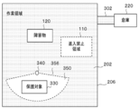
- the moving body 150 moves inside the region 100.
- an entry prohibited area 110 where entry of the mobile body 150 is prohibited and (ii) an obstacle 120 where the mobile body 150 cannot enter are arranged in the area 100.
- a plurality of entry prohibition areas 110 may be arranged inside the area 100.
- a plurality of obstacles 120 may be arranged inside the region 100.
- the moving body 150 is permitted to move within the area 100 except for (i) the entry prohibition area 110 and (ii) the area where the obstacle 120 is arranged.
- the region 100 may be an example of a region where entry of the moving body 150 is permitted.
- the region 100 may be a region surrounded by the boundary 106.
- the boundary 106 may have a linear shape, or may have a strip shape wider than the linear boundary.
- the boundary 106 distinguishes between the inside of the region 100 and the outside of the region 100.
- the boundary 106 may be a physically set geographical boundary or a virtually set geographical boundary.
- the boundary 106 may be configured by a single continuous boundary, or may be configured by a combination of a plurality of boundaries.
- the entry prohibition area 110 may be an area surrounded by the boundary 116.
- the boundary 116 may have a linear shape, or may have a strip shape that is wider than the linear boundary.
- the boundary 116 distinguishes between an area where the mobile object 150 is allowed to enter inside the area 100 and an area where the mobile object 150 is prohibited from entering inside the area 100.
- the boundary 116 may be a physically set geographical boundary or a virtually set geographical boundary.
- the boundary 116 may be configured by a single continuous boundary, or may be configured by a combination of a plurality of boundaries.
- Physically set geographic boundaries include (i) boundaries defined by naturally or artificially formed structures, (ii) boundaries defined by sprayed chemicals, (iii) visible Examples include boundaries defined by electromagnetic waves such as light rays, infrared rays, and ultraviolet rays, (iv) boundaries defined by magnetic fields, and (v) boundaries defined by sound waves or ultrasonic waves.
- naturally formed structures include depressions, steps, slopes, lakes, and rivers.
- artificially formed structure include a passage, a groove, a tunnel, a building, a wire, a rope, a fence, a net, and a braille block.
- Examples of the virtually set geographical boundary include a geofence and a virtual wire.
- the virtual wire may be a geographical boundary defined by a virtual line set between a plurality of structures.
- the obstacle 120 prevents the moving body 150 from proceeding.
- the obstacle 120 may be an object that is difficult for the moving body 150 to pass safely compared to the moving performance of the moving body 150.
- the obstacle 120 distinguishes between an area where the mobile object 150 is allowed to enter inside the area 100 and an area where the mobile object 150 is prohibited from entering inside the area 100.
- the obstacle 120 may be an example of a boundary.
- the obstacle 120 may be a structure formed naturally or artificially.
- naturally formed structures include trees, rocks, mud, lakes, rivers, depressions, steps, and steep slopes.
- artificially formed structure include a block, a building, a groove, a wire, a rope, a fence, and a net.
- the region 100 may have one or more sub-regions 130 and one or more sub-regions 140 therein.
- the sub-region 130 and the sub-region 140 may be an example of a region where the moving body 150 is permitted to enter.
- the entry prohibition area 110 is arranged inside the sub area 130, and the obstacle 120 is arranged inside the sub area 140.
- the sub-region 130 and the sub-region 140 are not limited to this embodiment.
- the obstacle 120 is disposed inside the sub-region 130, and the entry prohibition region 110 is disposed inside the sub-region 140.
- the sub area 130 and the sub area 140 may be virtual areas used by the control device 152 to control the moving body 150. At least one of the position, size, and shape of the sub-region 130 may change with time or may not change with time.
- the sub-region 130 may be a region surrounded by the boundary 136.
- the boundary 136 may be a geographical boundary that is virtually set. At least one of the position, size, and shape of the sub-region 140 may change with time or may not change with time.
- the sub-region 140 may be a region surrounded by the boundary 146.
- the boundary 146 may be a geographical boundary that is virtually set.
- the sub-region 130 may be a region where the value of the first parameter in the region satisfies a specific condition regarding the first parameter.
- the sub-region 140 may be a region where the value of the first parameter in the region does not satisfy the specific condition related to the first parameter.
- Examples of the first parameter include (i) the degree of completion of map information indicating an area where the mobile object 150 is permitted to enter, and (ii) the estimation accuracy of the self-position of the mobile object 150.
- the sub-region 140 may be a region where the value of the first parameter in the region satisfies other conditions related to the first parameter.
- the sub-region 140 may be a region where the value of the second parameter in the region satisfies the condition relating to the second parameter.
- the second parameter may be a parameter different from the first parameter.
- control device 152 controls the moving body 150.
- the details of the control device 152 will be described by taking as an example the case where the control device 152 is arranged on the moving body 150.
- the control device 152 is not limited to this embodiment.
- the control device 152 may be at least a part of an external information processing device that can send and receive information to and from the mobile body 150 via a communication network, and is realized by the information processing device. May be.
- control unit 154 controls the moving body 150.
- the control unit 154 may control the movement of the moving body 150.
- the control unit 154 moves the mobile unit 150 based on at least one of (i) the degree of completion of map information indicating the area where the mobile unit 150 is permitted to enter and (ii) the position estimation accuracy of the mobile unit 150. May be controlled.
- the control unit 154 controls at least one of (i) the traveling speed and (ii) the traveling direction of the moving body 150.
- the control unit 154 may control an operation when the moving body 150 reaches at least one of the boundary 106, the boundary 116, the obstacle 120, the boundary 136, and the boundary 146.
- the control unit 154 controls the traveling direction of the moving body 150 by controlling the operation when the moving body 150 reaches at least one of the boundary 106, the boundary 116, the obstacle 120, the boundary 136, and the boundary 146. May be.
- the control unit 154 may control an operation when the moving body 150 returns from an arbitrary position inside the region 100 to the return position of the moving body 150.
- the control unit 154 includes (a) a case where the completeness of the map information at the position of the moving body 150 satisfies a predetermined first condition, and (b) the map information at the position of the moving body 150. At least one of (i) the traveling speed of the moving body 150 and (ii) the operation when the moving body 150 reaches an arbitrary boundary differs from the case where the degree of completion satisfies a predetermined second condition. Thus, the movement of the moving body 150 is controlled.
- the second condition may be a condition different from the first condition.
- the second condition may be a condition that the completeness of the map information does not satisfy the first condition.
- the control unit 154 sets (i) the set value of the traveling speed of the moving body 150 and the degree of completion of the map information is the second condition. (Ii) When the moving body 150 reaches an arbitrary boundary, the traveling direction of the moving body 150 is determined based on the probability model. When the completeness of the map information at the position of the moving body satisfies the first condition, the control unit 154 moves the moving body 150 so that the moving body 150 returns to the return position of the moving body 150 along the boundary 106 of the region 100. The movement of 150 may be controlled.
- control unit 154 (a) the position estimation accuracy of the moving body 150 satisfies a predetermined third condition, and (b) the position estimation accuracy of the moving body 150 is determined in advance.
- the mobile unit 150 is configured so that at least one of (i) the traveling speed of the mobile unit 150 and (ii) the operation when the mobile unit 150 reaches the boundary of the region is different from the case where the fourth condition is satisfied. Control movement.
- Each of the third condition and the fourth condition may be a condition different from the first condition and the second condition.
- the fourth condition may be a condition different from the third condition.
- the fourth condition may be a condition that the position estimation accuracy of the moving body 150 does not satisfy the third condition.
- the control unit 154 sets the traveling speed of the moving body 150 and the position estimation accuracy of the moving body 150 satisfies the fourth condition. And (ii) when the moving body 150 reaches an arbitrary boundary, the traveling direction of the moving body 150 is determined based on the probability model.
- the control unit 154 causes the moving body 150 to return to the return position of the moving body 150 along the boundary 106 of the region 100. The movement may be controlled.
- control unit 154 may control the moving body 150 by determining the moving mode of the moving body 150 according to the state of the moving body 150. For example, the control unit 154 determines the movement mode of the moving body 150 based on at least one of (i) the degree of completion of the map information and (ii) the position estimation accuracy of the moving body 150.
- the movement mode is information for defining at least one of (i) a setting relating to at least one of the traveling speed and the traveling direction, and (ii) an algorithm for determining at least one of the traveling speed and the traveling direction.
- the traveling direction of the moving body 150 is determined by the operation of the moving body 150 when the moving body 150 reaches an arbitrary boundary, for example. Examples of the arbitrary boundary include the boundary 106 of the region 100, the boundary 116 of the entry prohibition region 110, the periphery of the obstacle 120, the boundary 136 of the sub-region 130, the boundary 146 of the sub-region 140, and the like.
- the movement mode As an example of the movement mode, (i) a mode in which an arbitrary work is performed on a work target placed in the area 100 during movement, and (ii) the above work is not performed during the movement.
- a mode for creating map information (iii) a mode for creating map information while carrying out the above work while moving; and (iv) carrying out the above work or creating map information while moving.
- a mode for moving while suppressing the generation of noise (vi) a mode for returning to the return position, and the like.
- the above movement mode defines, for example, at least one of a setting related to the traveling speed and an algorithm for determining the traveling speed.
- the movement mode described above may further define an operation when the moving body 150 reaches an arbitrary boundary.
- the movement mode include (i) a mode of moving along a predetermined route (sometimes referred to as a program mode), and (ii) moving along the boundary after reaching a known boundary.
- Mode sometimes referred to as a guide mode
- Iv A mode in which, after arriving at an arbitrary boundary, turning in a direction determined based on an arbitrary probability model and continuing to move (sometimes referred to as a first random mode).
- V A mode in which the movement is continued in a direction determined based on an arbitrary probability model with constraints after reaching an arbitrary boundary (referred to as a second random mode).
- (Vi) (vi) A mode in which a plurality of parallel paths move while repeating straight movement and turning so that a plurality of parallel paths are arranged without gaps or with a predetermined gap (sometimes referred to as a parallel mode). Is done.
- Examples of the shape of the path in the parallel mode include a straight line shape, a curved line shape, a zigzag shape, and a combination thereof.
- the movement mode defines the operation of the moving body 150 when the moving body 150 reaches an arbitrary boundary.
- the movement mode may further define at least one of a setting relating to the traveling speed and an algorithm for determining the traveling speed.
- control unit 154 generates data (may be referred to as log data) for generating map information indicating an area where the mobile object 150 is allowed to enter while moving within the area 100. get.
- the control unit 154 may generate map information based on the acquired log data.
- the control unit 154 may determine whether to acquire log data according to the position of the moving body 150. For example, when the degree of completion of the map information at the position of the moving body 150 is equal to or greater than a predetermined threshold or exceeds the threshold, the control unit 154 determines not to acquire log data at the position. The control unit 154 may determine whether or not to acquire log data based on the estimation accuracy of the position of the moving body 150. For example, when the position estimation accuracy is equal to or less than a predetermined threshold or less than the threshold, the control unit 154 determines not to acquire log data at the position.
- the completeness of the map information may be defined as the ratio of the area where the creation of the map information is completed with respect to the entire specific area.
- the degree of completion of the map information may be defined as the degree of completion of the update work.
- the degree of completion of the map information is defined as the ratio of the area in which the map information update work is completed among the areas that are the target of the map information update work.
- the completeness of the map information in the sub-region is calculated.
- the shape and size of each sub-region are not particularly limited.
- the completeness of the map information in each sub-region is, for example, (i) the number of log data already acquired within the sub-region, and (ii) the geographical distribution of log data already acquired within the sub-region. And (iii) is determined based on at least one of the ratio of the area of the area where the moving body 150 has already passed within the sub area to the area of the sub area.
- control unit 154 may use the degree of map information of the sub area as the degree of completion of the map information of the moving object 150 located inside the specific sub area.
- control unit 154 may determine the sub area where the moving body 150 is located based on the traveling direction of the moving body 150.
- the completeness of the map information is calculated for each position of the moving body 150.
- the position, size, and shape of each of the plurality of sub-regions are determined in advance, and the completeness of the map information is calculated for each sub-region.
- a virtual area for calculating the degree of completion of the map information around the moving body 150 (when referred to as a calculation area) Is set).
- the calculation area may be set so that the moving body 150 is included in the calculation area, or may be set at a position away from the moving body 150.
- the calculation area may be set at an arbitrary position in the traveling direction of the moving body 150.
- the shape and size of the calculation area and the position of the moving body 150 in the calculation area are not particularly limited.
- the completeness of the map information is, for example, (i) the number of log data already acquired inside the calculation area, (ii) the geographical distribution of log data already acquired inside the calculation area, and (iii) the calculation area The area where the moving body 150 has already passed within the calculation area with respect to the shortest distance between the position indicated by the log data already acquired inside the position and the position of the moving body 150 and (iv) the area of the calculation area Is determined based on at least one of the following ratios. Note that the degree of completeness of the map information may be calculated based on the shortest distance between the position indicated by the already acquired log data and the position of the moving body 150 without setting the calculation area.
- the completeness of the map information may be represented by continuous numerical values or by stepwise division.
- Examples of the evaluation based on the stepwise classification include two-step evaluation, three-step evaluation, five-step evaluation, and ten-step evaluation.
- Each division may be distinguished by a symbol or a character, and may be distinguished by a number.
- the control unit 154 may acquire the above data at predetermined time intervals.
- the control unit 154 may acquire the above data at a predetermined time.
- the control unit 154 may acquire the above data every time the moving body 150 travels a predetermined distance.
- the control unit 154 may acquire the above data when the moving body 150 reaches a predetermined position.
- the control unit 154 may acquire the above data when the surrounding environment of the moving body 150 satisfies a predetermined condition.
- control unit 154 includes information indicating the position of the moving body 150 and information indicating whether or not the moving body 150 can travel at the position while the moving body 150 is moving within the region 100.
- information indicating the position of the moving body 150 is stored in an arbitrary storage device. While the moving body 150 is moving inside the region 100, the control unit 154 includes information indicating the position of the moving body 150, information indicating the traveling direction of the moving body 150 at the position, and the moving body 150 at the position. May be stored in an arbitrary storage device in association with information indicating whether or not the process can proceed.
- the control unit 154 may estimate the position of the moving body 150 by an arbitrary position estimation method.
- the control unit 154 may estimate the position of the moving body 150 and determine the estimation accuracy of the position (sometimes referred to as positioning accuracy).
- the control unit 154 estimates the position of the moving body 150 based on the GPS signal.
- the GPS signal may include information indicating the positioning accuracy.
- the control unit 154 estimates the position of the moving body 150 based on a beacon signal from a beacon transmitter installed in or around the area 100.
- the control unit 154 estimates the position of the moving body 150 based on the radio wave intensity of radio waves from a plurality of radio wave transmitters.
- the control unit 154 analyzes an image around the moving body 150 and estimates the position of the moving body 150.
- control unit 154 controls the movement of the moving body 150 based on at least one of (i) the degree of completion of map information and (ii) the position estimation accuracy of the moving body 150. .
- the moving body 150 can move efficiently inside the region 100.
- the work machine creates map information while moving inside the work area in a low-speed parallel mode. Therefore, the period until the map information is completed is long, and until the map information is completed, it is difficult to move the work implement at high speed inside the work area.
- the control unit 154 controls the movement of the moving body 150 according to the degree of completion of the map information.
- the control unit 154 (i) travels in an appropriate movement mode and movement speed according to the purpose in an area where the degree of completion of map information is relatively large, and (ii) an area where the degree of completion of map information is relatively small.
- the mobile body 150 is controlled so that the vehicle travels in a movement mode and a movement speed that prioritize the creation of map information. Thereby, the period until map information is completed can be shortened.
- map information can be created while the moving body 150 is moving in at least a part of the region 100 in the first random mode or the second random mode. Therefore, it is possible to shorten the period until the approximate positions of the entry prohibition area 110 and the obstacle 120 are reflected in the map information. As a result, even before the map information is completed, the control unit 154 can move the moving body 150 at a high speed in an area where the degree of completion of the map information is relatively large. Thereby, the moving body 150 can move efficiently inside the region 100.
- control unit 154 controls the movement of the moving body 150 according to the position estimation accuracy of the moving body 150.
- control unit 154 (i) travels in an appropriate movement mode and movement speed according to the purpose in an area where the position estimation accuracy is relatively large, and (ii) the first in an area where the position estimation accuracy is relatively small.
- the moving body 150 is controlled to run in the random mode or the second random mode. Thereby, the moving body 150 can move efficiently inside the region 100.
- Each unit of the moving body 150 may be realized by hardware, may be realized by software, or may be realized by hardware and software.
- the constituent elements realized by the software define the operations related to the constituent elements in an information processing apparatus having a general configuration. It may be realized by starting software or a program.
- the information processing apparatus includes (i) a data processing apparatus having a processor such as a CPU and GPU, ROM, RAM, a communication interface, and (ii) a keyboard, a touch panel, a camera, a microphone, various sensors, a GPS receiver, and the like.
- An input device (iii) an output device such as a display device, a speaker, and a vibration device, and (iv) a storage device (including an external storage device) such as a memory and an HDD may be provided.
- the data processing apparatus or the storage device may store the software or the program.
- the software or program is executed by a processor to cause the information processing apparatus to execute an operation defined by the software or program.
- the above software or program may be stored in a non-transitory computer-readable recording medium.
- the above software or program may be a control program for controlling a mobile object having an autonomous movement function.
- the control program moves the computer based on at least one of the completeness of the map information indicating whether or not the vehicle is allowed to enter at each position inside the area where the mobile object is permitted and the position estimation accuracy of the mobile object.
- the program for performing the control step which controls a movement of a body may be sufficient.
- the computer may be (i) a computer mounted on the mobile unit 150, or (ii) a computer external to the mobile unit 150 and controlling the mobile unit 150 via a communication network. May be.
- FIG. 2 schematically shows an example of the system configuration of the management system 200.
- the management system 200 includes a lawn mower 210, a warehouse 220, and a management server 230.
- a charging station 222 is arranged in the warehouse 220.
- the lawn mower 210 may be an example of a moving body and a work machine. Part of the lawn mower 210 may be an example of a control unit and a control device.
- the warehouse 220 may be an example of a return position.
- the user terminal 22 may be an example of a control unit and a control device.
- the management server 230 may be an example of a control unit and a control device.
- Each part of the management system 200 may send and receive information to and from each other.
- the lawn mower 210 transmits and receives information to and from at least one of the user terminal 22 and the management server 230 via the communication network 20.
- the charging station 222 is connected to the communication network 20
- the lawn mower 210 may send and receive information to / from the user terminal 22 and the management server 230 via the charging station 222.
- the communication network 20 may be a wired communication transmission line, a wireless communication transmission line, or a combination of a wireless communication transmission line and a wired communication transmission line.
- the communication network 20 may include a wireless packet communication network, the Internet, a P2P network, a dedicated line, a VPN, a power line communication line, and the like.
- the communication network 20 may include (i) a mobile communication network such as a mobile phone network, (ii) a wireless MAN (for example, WiMAX (registered trademark)), a wireless LAN (for example, WiFi (registered trademark)). Or a wireless communication network such as Bluetooth (registered trademark), Zigbee (registered trademark), NFC (Near Field Communication), or the like.
- the user terminal 22 is a communication terminal used by the user of the management system 200 or the lawn mower 210, and details thereof are not particularly limited.
- Examples of the user terminal 22 include a personal computer and a portable terminal.
- Examples of the portable terminal include a mobile phone, a smartphone, a PDA, a tablet, a notebook computer or a laptop computer, and a wearable computer.
- the management system 200 manages the work area 202.
- the work area 202 may be an area where the lawn mower 210 is permitted to enter.
- the management system 200 manages the state of the work area 202.
- the management system 200 may manage the state of an object (may be referred to as a work target) that is a work target performed in the work area 202.
- the management system 200 may manage work performed in the work area 202.
- the management system 200 manages a work schedule.
- the work schedule may be information that defines at least one of a work execution time, a work execution place, a work execution subject, a work target, and a work content.
- the management system 200 manages the lawn mower 210.
- the lawn mower 210 may be an example of a work execution entity.
- the management system 200 manages the state of the lawn mower 210.
- the management system 200 manages the position of the lawn mower 210, the traveling direction, the traveling speed, the remaining amount of energy (for example, the remaining amount of the battery), the schedule of work performed by the lawn mower 210, and the like.
- a wire 206 having a conductive member is embedded at the boundary between the work area 202 and the non-work area 204.
- a voltage is applied to both ends of the wire 206 and a current flows through the wire 206, a magnetic field is generated around the wire 206.
- the lawn mower 210 recognizes the magnetic field generated by the wire 206 as a boundary that distinguishes the inside of the work area 202 from the outside of the work area.
- the wire 206 may be an example of a boundary.
- the magnetic field generated by the wire 206 may be an example of a boundary.
- the burying machine may transmit information indicating the installation position of the wire 206 to the management server 230 during the installation work of the wire 206.
- the management server 230 can manage the position of the wire 206 in the work area 202.
- the management system 200 may manage work machines other than the lawn mower 210.
- the work machine may perform various operations.
- the types of work include (i) civil engineering work, (ii) construction work, (iii) cultivation work of plants or agricultural products, (iv) snow removal work, (v) cleaning work, (vi) transporting work, (vii) monitoring Security or security work is exemplified.
- Examples of the cultivation work include sowing seeds, pruning, lawn mowing, mowing, water supply, fertilizing, putting in soil, and weeding.
- the work machine may have an autonomous movement function.
- the work machine may be an example of a moving body.
- the work area 202 may have the same configuration as the area 100 within a technically consistent range.
- the area 100 may have the same configuration as the work area 202 within a technically consistent range.
- the wire 206 may have the same configuration as the boundary 106 within a technically consistent range.
- the boundary 106 may have the same configuration as the wire 206 within a technically consistent range.
- the lawn mower 210 may have the same configuration as the moving body 150 within a technically consistent range.
- the moving body 150 may have the same configuration as the lawn mower 210 within a technically consistent range.
- the lawn mower 210 has an autonomous movement function and autonomously travels inside the work area 202.
- the lawn mower 210 cuts the lawn growing inside the work area 202.
- the lawn mower 210 may travel while cutting the turf, or may travel without cutting the turf.
- Turf may be an example of a work target. Details of the lawn mower 210 will be described later.
- the warehouse 220 stores the lawn mower 210.
- the lawn mower 210 leaves the warehouse 220 and moves toward the work area 202.
- the lawn mower 210 returns to the warehouse 220 when the work in the work area 202 is completed.
- the charging station 222 charges the lawn mower 210.
- the management server 230 manages various types of information regarding the work area 202.
- the management server 230 manages mapping data indicating the geographical distribution of various attributes in the work area 202.
- the mapping data may be an example of map information.
- Examples of the attributes include permission / inhibition of the lawn mower 210, work target attributes, various parameters related to the work, positioning accuracy of the lawn mower 210, and the like.
- the management server 230 may manage the state of the work area 202.
- the management server 230 may manage the status of the work target.
- the management server 230 may manage work performed in the work area 202.
- the management server 230 may manage the state of the lawn mower 210.
- the management server 230 manages the position of the lawn mower 210, the traveling direction, the traveling speed, the remaining energy, the schedule of work performed by the lawn mower 210, and the like. Details of the management server 230 will be described later.
- Each unit of the management system 200 may be realized by hardware, may be realized by software, or may be realized by hardware and software. At least a part of each part of the management system 200 may be realized by a single server or a plurality of servers. At least a part of each part of the management system 200 may be realized on a virtual server or a cloud system. At least a part of each part of the management system 200 may be realized by a personal computer or a portable terminal. Examples of the portable terminal include a mobile phone, a smartphone, a PDA, a tablet, a notebook computer or a laptop computer, and a wearable computer.
- the management system 200 may store information using a distributed ledger technology such as a block chain or a distributed network.
- the constituent elements realized by the software define operations related to the constituent elements in an information processing apparatus having a general configuration. It may be realized by starting software or a program.
- the information processing apparatus includes (i) a data processing apparatus having a processor such as a CPU and GPU, ROM, RAM, a communication interface, and (ii) a keyboard, a touch panel, a camera, a microphone, various sensors, a GPS receiver, and the like.
- An input device, (iii) an output device such as a display device, a speaker, and a vibration device, and (iv) a storage device (including an external storage device) such as a memory and an HDD may be provided.
- the data processing apparatus or the storage device may store the software or the program.
- the software or program is executed by a processor to cause the information processing apparatus to execute an operation defined by the software or program.
- the above software or program may be stored in a non-transitory computer-readable recording medium.
- the above software or program may be a control program for controlling the lawn mower 210.
- the control program controls the movement of the lawn mower 210 based on at least one of the completeness of the map information indicating the area where the lawn mower 210 is permitted to enter and the position estimation accuracy of the lawn mower 210. It may be a program for executing the procedure.
- the processor may be (i) the lawn mower 210 processor or (ii) the management server 230 processor.
- the processor of the management server 230 may be a physical processor or a virtual processor.
- the processor may be an example of a computer.
- FIG. 3 schematically shows an example of the work area 202.
- the work area 202 may be an area surrounded by the wire 206.
- a passage 302 that connects the entrance / exit of the warehouse 220 and a part of the work area 202 is disposed between the warehouse 220 and the work area 202.
- one or more entry prohibition areas 110, one or more obstacles 120, and one or more protection objects 330 are arranged inside the work area 202.
- a protected area setting device 340 is disposed inside the work area 202.
- the protection target 330 may be a target to be protected from damage caused by the operation of the lawn mower 210.
- the protection area setting device 340 sets a protection area 350 for preventing the lawnmower 210 from approaching the protection object 330 around the protection object 330.
- the protection area 350 may have the same configuration as the entry prohibition area 110 within a technically consistent range.
- the protection area setting device 340 sets at least a part of the boundary 356 of the protection area 350 by emitting electromagnetic waves, sound waves, ultrasonic waves, and the like.
- the protection area setting device 340 may set at least a part of the boundary 356 of the protection area 350 by emitting directional electromagnetic waves, sound waves, ultrasonic waves, or the like.
- the boundary 356 of the protection region 350 may be configured by a single continuous boundary or may be configured by a combination of a plurality of boundaries. This prohibits the lawn mower 210 from entering the protection area 350.
- mapping data [Overview of mapping data] 4 and 5, an outline of mapping data indicating whether or not the lawn mower 210 is allowed to enter at each position in the work area 202 will be described. An example of a method for calculating the degree of completion of mapping data will be described with reference to FIGS.
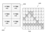
- FIG. 4 schematically shows an example of a map 420 that expresses whether or not an entry is permitted in a map format.
- the work area 202 is divided into, for example, a sub area 402, a sub area 403, a sub area 404, a sub area 405, a sub area 406, and a sub area 407.
- the degree of completion of mapping data is calculated for each sub-region.
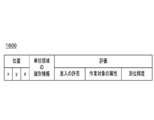
- the map 420 shows evaluations regarding whether or not the lawn mower 210 is allowed to enter at each position in the sub-region 407.
- the map 420 virtually divides the sub-region 407 by a plurality of unit regions having a predetermined shape and size. The plurality of unit areas are continuously arranged without overlapping. The area of the unit region may be larger than the projected area of the lawn mower 210 on the ground, or smaller than the projected area.
- the map 420 indicates whether or not the lawn mower 210 is allowed to enter the unit area for each unit area.
- ⁇ and ⁇ indicate unit areas for which log data has already been acquired, and “-” indicates unit areas for which log data has not yet been acquired.
- ⁇ indicates a unit area in which the lawn mower 210 is allowed to enter, and “ ⁇ ” indicates a unit area in which the lawn mower 210 is not allowed to enter, or that the lawn mower 210 enters. Indicates the unit area that cannot be used. It should be noted that the method for expressing whether the lawn mower 210 is permitted to enter is not limited to the present embodiment.
- the unit area may be regarded as a unit area where the lawn mower 210 is not allowed to enter or a unit area where the lawn mower 210 cannot enter.
- an evaluation for example, “ ⁇ ” or “ ⁇ ” indicated by a large number of the plurality of log data is performed. It may be regarded as an evaluation related to the unit area.
- the completeness of the mapping data in the sub-region 407 is calculated as a ratio of A to B (A / B) using A and B defined as follows, for example.
- A is the number of unit areas for which log data has already been acquired.
- B is the number of all unit areas included in the sub area 407.
- the degree of completeness of the mapping data may be calculated by converting the above ratio (A / B) into an evaluation based on stepwise classification.
- FIG. 5 schematically shows an example of a map 520 that expresses whether or not an entry is permitted in a map format.
- the map 520 shows an evaluation regarding whether or not the lawn mower 210 is allowed to enter at each position in the sub-region 407.
- a unit area for which log data has not yet been acquired (represented as “ ⁇ ” in the figure) is surrounded by a unit area whose evaluation is “ ⁇ ”.
- the completeness of the mapping data in the sub-region 407 may be calculated as a ratio of A to B (A / B) using A and B defined as follows.
- A is the number of unit areas for which log data has already been acquired.
- B is obtained by subtracting “the number of unit areas for which log data has not yet been acquired, surrounded by unit area positions whose evaluation is ⁇ ” from “the number of all unit areas included in the sub area 407”. Value.
- the degree of completeness of the mapping data may be calculated by converting the above ratio (A / B) into an evaluation based on stepwise classification.
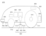
- FIG. 6 schematically shows an example of the internal configuration of the lawn mower 210.
- the lawn mower 210 includes a housing 602.
- the lawn mower 210 includes a pair of front wheels 612 and a pair of rear wheels 614 at the bottom of the housing 602.
- the lawn mower 210 may include a pair of traveling motors 616 that drive each of the pair of rear wheels 614.
- the lawn mower 210 includes a work unit 620.
- the work unit 620 includes, for example, a blade disk 622, a cutter blade 624, a work motor 626, and a shaft 628.
- the lawn mower 210 may include a position adjustment unit 630 that adjusts the position of the work unit 620.
- the blade disk 622 is connected to a work motor 626 through a shaft 628.
- the cutter blade 624 may be a cutting blade for cutting turf.
- the cutter blade 624 is attached to the blade disk 622 and rotates with the blade disk 622.
- the work motor 626 rotates the blade disk 622.
- the blade disk 622 and the cutter blade 624 may be an example of a cutting member for cutting a work target.
- the lawn mower 210 includes a battery unit 640, a user interface 650, a boundary detection unit 662, a proximity detection unit 664, and a distance measurement unit 666 inside or on the housing 602.
- the sensor unit 670 and the control unit 680 are provided.
- the control unit 680 may be an example of a control unit and a control device.
- the battery unit 640 supplies power to each part of the lawn mower 210.
- the user interface 650 receives user input.
- the user interface 650 outputs information to the user. Examples of the user interface 650 include a keyboard, a pointing device, a microphone, a touch panel, a display, and a speaker.
- the boundary detection unit 662 detects the wire 206 in the work area 202.
- the boundary detection unit 662 may detect an arbitrary boundary arranged in the work area 202.
- the boundary detection unit 662 may include a sensor for detecting a physically set geographical boundary.
- the boundary detection unit 662 may detect the virtually set geographical boundary based on the position information of the virtually set geographical boundary and the position information of the lawn mower 210. If a boundary is detected, boundary detection unit 662 may send a signal to control unit 680 indicating that the boundary has been detected.
- the proximity detection unit 664 detects an object existing in the traveling direction of the lawn mower 210.
- the proximity detection unit 664 is disposed on at least a part of the outer periphery of the lawn mower 210.
- the proximity detection unit 664 is disposed in front of the lawn mower 210, for example.
- the proximity detection unit 664 may be disposed on the front and both sides of the lawn mower 210.
- the proximity detection unit 664 may include a contact type proximity detection sensor.
- the proximity detection unit 664 may include a non-contact type proximity detection sensor.
- the distance measuring unit 666 measures the distance between the distance measuring unit 666 and the ground. Thereby, the ranging unit 666 can acquire information indicating the state of the ground in the traveling direction of the lawn mower 210.
- the distance measuring unit 666 is disposed in front of the lawn mower 210, for example.
- the distance measuring unit 666 may include a contact-type distance measuring sensor.
- the distance measuring unit 666 may include a non-contact type distance measuring sensor.
- the ranging unit 666 may transmit a signal indicating the ranging result to the control unit 680.
- the distance measuring unit 666 may detect a step or a head formed on the ground in the traveling direction of the lawn mower 210 based on the distance measurement result.
- the ranging unit 666 may detect a step or a head that is likely to affect the stability or safety of the lawn mower 210.
- the distance measuring unit 666 sends a signal indicating that the step or head has been detected to the control unit. 680 may be transmitted.
- the sensor unit 670 includes various sensors.
- the sensor unit 670 may include various internal sensors.
- the sensor unit 670 may include various external sensors.
- As a sensor GPS signal receiver, beacon receiver, radio wave intensity measuring device, millimeter wave sensor, camera, infrared camera, microphone, ultrasonic sensor, acceleration sensor, angular velocity sensor, wheel speed sensor, load sensor, idling detection sensor, Examples include a magnetic sensor, a geomagnetic sensor (sometimes referred to as an orientation sensor, an electronic compass, etc.), a temperature sensor, a humidity sensor, a soil moisture sensor, and the like.
- the sensor unit 670 may transmit the outputs of various sensors to the control unit 680.
- the wheel speed sensor may be a rotary encoder that detects the rotation angle or the rotation speed of the wheel.
- control unit 680 controls the operation of the lawn mower 210.
- control unit 680 controls the movement of the lawn mower 210 by controlling the pair of travel motors 616.
- control unit 680 controls the work motor 626 to control the work of the lawn mower 210.
- the control unit 680 may control the lawn mower 210 based on an instruction from the management server 230. For example, the control unit 680 controls the lawn mower 210 according to the command generated by the management server 230.
- the control unit 680 may execute various determination processes.
- the control unit 680 may execute at least one of the determination processes in the determination processing unit 440.
- the control unit 680 may control the lawn mower 210 based on the result of the determination process. Details of the control unit 680 will be described later.
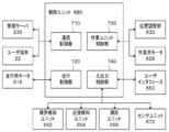
- FIG. 7 schematically shows an example of the internal configuration of the control unit 680.
- the control unit 680 includes a communication control unit 710, a travel control unit 720, a work unit control unit 730, and an input / output control unit 740.
- the travel control unit 720 may be an example of a control unit and a control device.
- the communication control unit 710 controls communication with a device outside the lawn mower 210.
- the communication control unit 710 may be a communication interface corresponding to one or a plurality of communication methods. Examples of external devices include the user terminal 22, the charging station 222, and the management server 230.
- the travel control unit 720 controls the travel motor 616 to control the movement of the lawn mower 210.
- the travel control unit 720 controls autonomous travel of the lawn mower 210.
- the traveling control unit 720 controls at least one of the movement mode, the traveling speed, the traveling direction, and the traveling route of the lawn mower 210.
- the traveling control unit 720 may monitor the current value of the traveling motor 616. Details of the travel control unit will be described later.
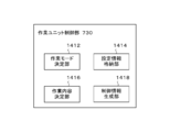
- the work unit control unit 730 controls the work unit 620.
- the work unit control unit 730 may control at least one of the work mode, the work type, the work intensity, and the work execution timing of the work unit 620.
- the work unit control unit 730 controls the work motor 626 to control the work intensity of the work unit 620.
- the work unit control unit 730 may control the position adjustment unit 630 to control the work intensity of the work unit 620.
- the work unit control unit 730 may monitor the current value of the work motor 626. Details of the travel control unit will be described later.
- the input / output control unit 740 receives input from at least one of the user interface 650, the boundary detection unit 662, the proximity detection unit 664, the distance measurement unit 666, and the sensor unit 670.
- the input / output control unit 740 outputs information to the user interface 650.
- the input / output control unit 740 may control at least one of the user interface 650, the boundary detection unit 662, the proximity detection unit 664, the distance measurement unit 666, and the sensor unit 670.
- the input / output control unit 740 controls the device by adjusting the setting of at least one of the user interface 650, the boundary detection unit 662, the proximity detection unit 664, the distance measurement unit 666, and the sensor unit 670.
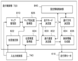
- FIG. 8 schematically shows an example of the internal configuration of the travel control unit 720.
- the travel control unit 720 may have the same configuration as the control device 152 or the control unit 154 within a technically consistent range.
- the control device 152 or the control unit 154 may have the same configuration as the travel control unit 720 within a technically consistent range.
- the travel control unit 720 includes a map management unit 810.
- the travel control unit 720 includes a position estimation unit 822, a position accuracy acquisition unit 824, and a map completeness acquisition unit 826.
- the travel control unit 720 includes a travel mode determination unit 830, a travel speed determination unit 832, a travel direction determination unit 834, a control information generation unit 836, and a setting information storage unit 840.
- each part of the traveling control unit 720 can transmit and receive information to and from each other without being limited to the arrows in the drawing.
- the map management unit 810 manages mapping data.
- the map management unit 810 may acquire log data.
- the map management unit 810 acquires data output from the boundary detection unit 662, the proximity detection unit 664, the distance measurement unit 666, and the sensor unit 670 from the input / output control unit 740 as log data.
- the map management unit 810 may acquire information regarding the work of the lawn mower 210 from the work unit control unit 730 as log data.
- the map management unit 810 may generate mapping data based on one or a plurality of log data.
- the map management unit 810 may generate mapping data indicating whether the lawn mower 210 is allowed to enter at each position in the work area 202.
- the map management unit 810 generates mapping data indicating (i) the attribute of the work target, (ii) various parameters relating to the work, or (iii) the positioning accuracy of the lawn mower 210 at each position in the work area 202. Also good.
- the map management unit 810 may calculate the degree of completion of mapping data. Details of the map management unit 810 will be described later.
- the position estimation unit 822 estimates the position of the lawn mower 210.
- the position estimation unit 822 may estimate the position of the lawn mower 210 by an arbitrary position estimation method. For example, the position estimation unit 822 acquires data output from the sensor unit 670 from the input / output control unit 740. The position estimation unit 822 may estimate the current position of the lawn mower 210 based on the above data. The position estimation unit 822 may calculate the estimation accuracy of the position of the lawn mower 210. The position estimation unit 822 may transmit information indicating the estimation accuracy of the position of the lawn mower 210 to the position accuracy acquisition unit 824.
- the position accuracy acquisition unit 824 acquires information indicating the estimation accuracy of the position of the lawn mower 210 estimated by the position estimation unit 822.
- the position accuracy acquisition unit 824 may acquire information indicating the estimated accuracy of the position of the lawn mower 210 from the sensor unit 670 via the input / output control unit 740.
- the position accuracy acquisition unit 824 acquires information indicating the positioning accuracy included in the GPS signal received by the sensor unit 670.
- the position accuracy acquisition unit 824 may acquire information indicating the estimation accuracy of the position of the lawn mower 210 from the position estimation unit 822.
- the map completeness acquisition unit 826 acquires information indicating the completeness of the mapping data at the position of the lawn mower 210 estimated by the position estimation unit 822. For example, the map completeness acquisition unit 826 acquires information indicating the current position of the lawn mower 210 from the position estimation unit 822. The map completeness acquisition unit 826 transmits information indicating the current position of the lawn mower 210 to the map management unit 810 and requests information indicating the completeness of the mapping data at the current position of the lawn mower 210. Thereby, the map completeness acquisition unit 826 can acquire information indicating the completeness of the mapping data at the current position of the lawn mower 210.
- the traveling mode determination unit 830 determines the traveling mode of the lawn mower 210.
- the traveling mode determination unit 830 may, for example, (i) position estimation accuracy at the current position of the lawn mower 210, (ii) completeness of mapping data at the current position of the lawn mower 210, (iii) an instruction from the user, and ( iv) The travel mode of the lawn mower 210 is determined based on at least one of the times.
- information indicating the position estimation accuracy at the current position of the lawn mower 210 is input from the position accuracy acquisition unit 824 to the travel mode determination unit 830.
- the travel mode determination unit 830 determines the travel mode of the lawn mower 210 based on the position estimation accuracy at the current position of the lawn mower 210.
- the traveling mode determination unit 830 reduces the traveling speed of the lawn mower 210 compared to the case where the position estimation accuracy is larger than the threshold.
- the travel mode of the lawn mower 210 is determined.
- the traveling mode determination unit 830 is configured such that when the position estimation accuracy is smaller than a predetermined threshold, the traveling speed of the lawn mower 210 is larger than when the position estimation accuracy is larger than the threshold.
- the travel mode of the lawn mower 210 may be determined.
- the traveling mode determination unit 830 may select the first random mode or the second random mode as the traveling mode of the lawn mower 210.
- the traveling mode determination unit 830 may select the parallel mode or the program mode as the traveling mode of the lawn mower 210.
- information indicating the completeness of the mapping data at the current position of the lawn mower 210 is input from the map completeness acquisition unit 826 to the travel mode determination unit 830.
- the travel mode determination unit 830 determines the travel mode of the lawn mower 210 based on the completeness of the mapping data at the current position of the lawn mower 210.
- the traveling mode determination unit 830 selects the second random mode as the traveling mode of the lawn mower 210.
- the traveling mode determination unit 830 selects the parallel mode, the program mode, or the first random mode as the traveling mode of the lawn mower 210.
- the traveling mode determination unit 830 may select the first random mode or the second random mode as the traveling mode of the lawn mower 210.
- the traveling mode determination unit 830 may select the parallel mode or the program mode as the traveling mode of the lawn mower 210.
- the traveling mode determination unit 830 reduces the traveling speed of the lawn mower 210 when the degree of completion of the mapping data is smaller than a predetermined threshold value as compared with the case where the degree of completion of the mapping data is larger than the threshold value. As such, the travel mode of the lawn mower 210 may be determined.
- the traveling mode determination unit 830 makes the traveling speed of the lawn mower 210 larger than when the degree of completion of mapping data is larger than the threshold. In addition, the travel mode of the lawn mower 210 may be determined.
- the traveling mode determination unit 830 when the proximity detection unit 664 or the distance measurement unit 666 detects the unknown obstacle 120, the traveling mode determination unit 830 causes the traveling speed of the lawn mower 210 to be less than or equal to a predetermined value. As described above, the travel mode of the lawn mower 210 may be determined. The travel mode determination unit 830 may determine the travel mode of the lawn mower 210 so that the lawn mower 210 performs the operation for detecting the position, size, range, or shape of the obstacle 120. . For example, the travel mode determination unit 830 selects the shape detection mode as the travel mode of the lawn mower 210.
- the travel mode determination unit 830 determines the travel mode of the lawn mower 210. May be returned to the travel mode before the obstacle 120 is detected.
- the traveling mode determination unit also operates when the operation for detecting the position, size, range, or shape of at least a part of the boundary is not performed. In step 830, the same processing as when the unknown obstacle 120 is found may be executed.
- the traveling mode determination unit 830 may The travel mode of the lawn mower 210 so that the machine 210 returns to the warehouse 220.
- the travel mode determination unit 830 may determine the travel mode of the lawn mower 210 so that the lawn mower 210 travels along the wire 206 in the work area 202 and returns to the warehouse 220.
- the traveling mode determination unit 830 may determine the traveling mode of the lawn mower 210 so that the lawn mower 210 moves at a higher speed than when the lawn mower 210 moves within the work area 202. For example, the travel mode determination unit 830 selects the guide mode as the travel mode of the lawn mower 210.
- the traveling speed determination unit 832 determines the traveling speed of the lawn mower 210. For example, the traveling speed determination unit 832 receives information indicating the movement mode of the lawn mower 210 from the travel mode determination unit 830. The traveling speed determination unit 832 refers to the setting information storage unit 840, and indicates information indicating at least one of (i) settings related to the traveling speed and (ii) an algorithm for determining the traveling speed corresponding to the input movement mode. To get. The traveling speed determination unit 832 determines the traveling speed of the lawn mower 210 based on information obtained by referring to the setting information storage unit 840.
- the traveling direction determination unit 834 determines the traveling direction of the lawn mower 210.
- the traveling direction determination unit 834 may determine the traveling direction of the lawn mower 210 based on the traveling mode selected by the traveling mode determination unit 830. As described above, the traveling direction of the lawn mower 210 is determined by, for example, the operation of the lawn mower 210 when the lawn mower 210 reaches an arbitrary boundary. When the lawn mower 210 reaches a boundary that distinguishes two adjacent sub-regions, the traveling direction determination unit 834 may determine not to turn on the boundary.
- the traveling direction determination unit 834 refers to the setting information storage unit 840, and indicates information indicating at least one of (i) a setting related to the traveling direction and (ii) an algorithm for determining the traveling direction corresponding to the input movement mode. To get.
- the traveling direction determination unit 834 determines the traveling direction of the lawn mower 210 based on information obtained by referring to the setting information storage unit 840.
- examples of the running mode include a program mode, a guide mode, a shape detection mode, a first random mode, a second random mode, and a parallel mode.
- the traveling direction determination unit 834 determines the traveling direction of the lawn mower 210 by the following procedure, for example.
- the traveling direction determination unit 834 determines the traveling direction of the lawn mower 210 after turning so that the lawn mower 210 moves on a predetermined route. For example, the traveling direction determination unit 834 determines the traveling direction of the lawn mower 210 after turning so that the lawn mower 210 turns in a predetermined direction at a predetermined position.
- the traveling direction determination unit 834 determines the traveling direction of the lawn mower 210 after turning so that the lawn mower 210 moves along the boundary. For example, the traveling direction determining unit 834 determines the traveling direction of the lawn mower 210 during the turning operation so that the lawn mower 210 repeats the turning operation until the extending direction of the boundary and the traveling direction after the turning are substantially parallel. decide. When the distance between the position of the lawn mower 210 and the representative point of the boundary exceeds a predetermined threshold after the lawn mower 210 starts moving along the boundary, the traveling direction determination unit 834 210 decides to change the direction of travel.
- the advancing direction determination part 834 determines the advancing direction of the lawn mower 210 after a course change so that the distance of the position of the lawn mower 210 and the representative point of a boundary may become small. In this case, for example, the lawn mower 210 moves in a zigzag shape along the boundary line.
- the traveling direction determination unit 834 causes the lawn mower 210 after turning so that the lawn mower 210 detects the position, size, range, or shape of at least a part of the boundary. Determine the direction of travel. For example, the traveling direction determination unit 834 determines the traveling direction of the lawn mower 210 after the turn so that the lawn mower 210 repeats the progression, boundary detection, retreat, and turning around the boundary.
- the traveling direction determination unit 834 may determine the traveling direction after the turn based on an arbitrary probability model. For example, the traveling direction determination unit 834 randomly determines the traveling direction after turning. The traveling direction determination unit 834 may determine the traveling direction of the lawn mower 210 after the rotation so that the traveling direction after the rotation satisfies a predetermined constraint condition. The traveling direction determination unit 834 may determine the traveling direction of the lawn mower 210 after the rotation so that the traveling direction after the rotation satisfies a predetermined constraint condition based on an arbitrary probability model.
- Constraint condition may be a condition that an angle formed by a traveling direction before turning and a traveling direction after turning is within a predetermined numerical range.
- the predetermined numerical range may be 90 degrees or less, preferably less than 90 degrees, more preferably 60 degrees or less, still more preferably 30 degrees or less, still more preferably 15 degrees or less, and even more preferably less than 15 degrees.
- the “angle between the traveling direction before turning and the traveling direction after turning” is the overlap of the starting point of the plane vector indicating the traveling direction before turning and the starting point of the plane vector indicating the traveling direction after turning. In this case, of the two angles formed by the two vectors, it may mean an angle that is 180 degrees or less.
- the traveling direction determination unit 834 determines the traveling direction after the turn based on an arbitrary probability model. For example, the traveling direction determination unit 834 randomly determines the traveling direction after turning.
- the traveling direction determination unit 834 determines the traveling direction of the lawn mower 210 after the rotation so that the traveling direction after the rotation satisfies a predetermined constraint condition.
- the traveling direction determination unit 834 may determine the traveling direction of the lawn mower 210 after the rotation so that the traveling direction after the rotation satisfies a predetermined constraint condition based on an arbitrary probability model.
- the constraint condition may be a condition that an angle formed between the extending direction of the boundary and the traveling direction after the rotation is within a predetermined numerical range.
- the predetermined numerical range is 15 degrees or more and 90 degrees or less, preferably more than 15 degrees and 90 degrees or less, more preferably 30 degrees or more and 90 degrees or less, further preferably 45 degrees or more and 90 degrees or less, and further preferably 60 degrees or more. It may be 90 degrees or less.
- the traveling direction after turning is limited to the direction from the boundary of the region toward the inside of the region.
- the angle between the extending direction of the boundary and the traveling direction after the turn is the above-mentioned when the starting point of the plane vector indicating the traveling direction after the turning is overlaid on the straight line indicating the extending direction of the boundary.
- it may mean an angle that is 90 degrees or less.
- the traveling direction determination unit 834 has a probability that the smaller one of the two candidates related to the traveling direction after the turn is smaller than the probability that the other is selected.
- the traveling direction of the lawn mower 210 after turning may be determined.
- the traveling direction determination unit 834 selects, as the traveling direction of the lawn mower 210 after the rotation, the smaller one of the two candidates related to the traveling direction after the rotation with respect to the traveling direction before the rotation.
- the traveling direction determination unit 834 is such that the probability that the smaller one of the two candidates related to the traveling direction after the turn and the traveling direction before the turn is selected is smaller than the probability that the other is selected.
- the traveling direction of the lawn mower 210 after turning may be determined.
- the constraint condition is lawn mowing. There may be a condition that the probability that the machine 210 is selected in the direction toward the region is larger than the probability that the other direction is selected. Similarly, when there is an area within the work area 202 where the degree of completion of the mapping data is smaller than a predetermined threshold, the constraint condition is that the probability that the lawn mower 210 is selected in the direction toward the area is: It may be a condition that it is larger than the probability that another direction is selected.
- the traveling direction determination unit 834 proceeds the lawn mower 210 after the rotation so that the angle formed by the traveling direction before the rotation and the traveling direction after the rotation is approximately 180 degrees. Determine the direction. Further, the traveling direction determination unit 834 determines the traveling direction of the lawn mower 210 during the turning operation so that the gap between the route before the turning and the route after the turning becomes an appropriate value.
- the traveling direction determination unit 834 may determine a return route to the warehouse 220. For example, when the lawn mower 210 completes the scheduled work, or when the lawn mower 210 receives a return command from the user terminal 22 or the management server 230, the traveling mode determination unit 830 causes the lawn mower 210 to work in the work area. The traveling mode of the lawn mower 210 is determined so as to return along the wire 206 of 202. When the lawn mower 210 reaches the wire 206, the traveling direction determination unit 834 determines which direction of the two extending directions of the wire 206 is to advance the lawn mower 210.
- the traveling direction determination unit 834 moves the lawn mower toward either of the two extending directions of the wire 206. It may be determined whether machine 210 is to proceed.
- control information generation unit 836 generates control information for controlling the traveling motor 616.
- the control information generation unit 836 may generate a control signal based on the travel mode determined by the travel mode determination unit 830.
- the control information generation unit 836 may generate a control signal based on the traveling speed determined by the traveling speed determination unit 832.
- the control information generation unit 836 may generate a control signal based on the traveling direction determined by the traveling direction determination unit 834.
- the control information generation unit 836 may transmit the generated control information to the traveling motor 616.
- control information generation unit 836 includes: (a) when the mapping data completeness at the position of the lawn mower 210 satisfies a predetermined first condition; and (b) the position of the lawn mower 210. And (ii) the speed of the lawn mower 210, and (ii) the operation when the lawn mower 210 reaches an arbitrary boundary. Control information is generated so that at least one of them is different.
- the second condition may be a condition different from the first condition.
- the first condition a condition that the degree of completion of mapping data is smaller than a predetermined threshold, a condition that the degree of completion of mapping data is less than or equal to a predetermined threshold, and a threshold that determines the degree of completion of mapping data Examples are a condition that the mapping data is greater than a predetermined threshold value, and a combination thereof.
- the second condition may be a condition that the completeness of the mapping data does not satisfy the first condition.
- the control information generation unit 836 sets the progress speed of the lawn mower 210 to be the first completeness of the mapping data.
- the traveling direction of the lawn mower 210 is determined based on a probability model, when the two conditions are satisfied.
- One or a plurality of control information is generated. More specifically, the first condition is a condition that the degree of completion of mapping data is equal to or lower than a predetermined threshold value or smaller than the threshold value, and the second condition is that the degree of completion of mapping data is higher than the above threshold value. It may be a condition that it is large or greater than or equal to the threshold value.
- the control information generation unit 836 may generate control information so that the traveling direction of the lawn mower 210 is limited.
- the traveling direction determination unit 834 determines the traveling direction of the lawn mower 210 after turning so that the traveling direction of the lawn mower 210 after turning satisfies a predetermined constraint condition based on an arbitrary probability model.
- the control information generation unit 836 generates one or a plurality of control information based on the determination result of the traveling direction determination unit 834.
- the constraint condition may be a condition that an angle formed between the extending direction of the boundary and the traveling direction after the rotation is within a predetermined numerical range.
- the predetermined numerical range is 15 degrees or more and 90 degrees or less, preferably more than 15 degrees and 90 degrees or less, more preferably 30 degrees or more and 90 degrees or less, further preferably 45 degrees or more and 90 degrees or less, and further preferably 60 degrees or more. It may be 90 degrees or less.
- the constraint condition is that the allowable range of the angle between the traveling direction of the lawn mower 210 and the extending direction of the boundary reached by the lawn mower 210 is smaller than when the degree of completeness of the mapping data does not satisfy the first condition.
- Condition may be sufficient.
- the second random mode is selected, the first random mode or the program mode is selected as the allowable range of the angle between the traveling direction of the lawn mower 210 and the extending direction of the boundary reached by the lawn mower 210. Small compared to the case. Therefore, for example, when the completeness of the mapping data is smaller than a predetermined threshold, the travel mode determination unit 830 selects the second random mode as the travel mode of the lawn mower 210, and the completeness of the mapping data is determined in advance. When the threshold value is larger than the threshold value, the above-described constraint condition is satisfied when the program mode or the first random mode is selected as the travel mode of the lawn mower 210.
- the control information generation unit 836 returns the lawn mower 210 to the warehouse 220, and when the map information completeness at the position of the lawn mower 210 satisfies the first condition, the lawn mower 210 uses the wire 206. 1 or a plurality of control information is generated so as to return to the warehouse 220.
- the control information generation unit 836 generates control information for causing the lawn mower 210 to go straight until the wire 206 is detected.
- the control information generation unit 836 generates a control signal that indicates which direction of the drawing direction of the wire 206 should proceed. Thereafter, the control information generation unit 836 generates a control signal so that the lawn mower 210 travels along the wire 206.
- the control information generation unit 836 may generate a control signal for instructing a set value of the traveling speed of the lawn mower 210.
- the control information generation unit 836 includes: (a) the position estimation accuracy of the lawn mower 210 satisfies a predetermined third condition; and (b) the position estimation accuracy of the lawn mower 210 is In a case where the predetermined fourth condition is satisfied, at least one of (i) the traveling speed of the lawn mower 210 and (ii) the operation when the lawn mower 210 reaches the boundary of the region is different. Generate a control signal.
- Each of the third condition and the fourth condition may be a condition different from the first condition and the second condition.
- the fourth condition may be a condition different from the third condition.
- the third condition a condition that the position estimation accuracy is smaller than a predetermined threshold, a condition that the position estimation accuracy is less than or equal to a predetermined threshold, a condition that the position estimation accuracy is larger than a predetermined threshold, and a position A condition that the estimation accuracy is equal to or higher than a predetermined threshold and a combination thereof are exemplified.
- the fourth condition may be a condition that the position estimation accuracy of the lawn mower 210 does not satisfy the third condition.
- the control information generation unit 836 indicates that (i) the set value of the traveling speed of the lawn mower 210 is the fourth condition and the position estimation accuracy of the lawn mower 210 is the fourth condition. 1 or 2 so that the direction of travel of the lawn mower 210 is determined based on a probability model when the lawn mower 210 reaches an arbitrary boundary.
- a plurality of control information is generated.
- the third condition is a condition that the position estimation accuracy is equal to or smaller than a predetermined threshold value or smaller than the threshold value
- the fourth condition is a position estimation accuracy that is larger than the threshold value or the threshold value.
- the condition may be as described above.
- the control information generation unit 836 returns the lawn mower 210 to the warehouse 220, and when the position estimation accuracy of the lawn mower 210 satisfies the third condition, the lawn mower 210 moves along the wire 206 to the warehouse.
- One or more control information is generated so as to return to 220.
- the control information generation unit 836 generates control information for causing the lawn mower 210 to go straight until the wire 206 is detected.
- the control information generation unit 836 generates a control signal that indicates which direction of the drawing direction of the wire 206 should proceed. Thereafter, the control information generation unit 836 generates a control signal so that the lawn mower 210 travels along the wire 206.
- the control information generation unit 836 may generate a control signal for instructing a set value of the traveling speed of the lawn mower 210.
- the traveling control unit 720 is not limited to this embodiment. In other embodiments, the travel control unit 720 may be disposed in the management server 230. A part of the traveling control unit 720 may be arranged in the management server 230.
- FIG. 9 schematically illustrates an example of a procedure in which the traveling direction determination unit 834 determines the turning angle when the parallel mode is selected as the movement mode of the lawn mower 210.
- a straight line 906 indicates the extending direction of the wire 206 at the position 920 where the lawn mower 210 reaches the wire 206.
- ⁇ 92 indicates an angle formed by the straight line 906 and the traveling direction 912 before turning.
- ⁇ 94 indicates an angle formed by the traveling direction 942 after the rotation and the straight line 906.
- the straight line 906 may be a straight line connecting the points 902 and 904 on the wire 206.
- a point 902 and a point 904 are ends of a region where the wire 206 and the shadow of the lawn mower 210 intersect when the lawn mower 210 is projected onto the wire 206 in a direction parallel to the traveling direction before turning.
- the points 902 and 904 may be the ends of the wire 206 on the working area 202 side.
- the lawn mower 210 first moves forward in the traveling direction 912 before turning, and approaches the wire 206. Lawn mower 210 detects wire 206 at position 920. Therefore, the lawn mower 210 moves backward to the turning position 930 in the direction of travel 922 during the turning operation.
- the angle formed by the traveling direction 922 and the traveling direction 912 is not particularly limited, but is approximately 180 degrees, for example.
- the lawn mower 210 moves toward the turning position 940 in the traveling direction 932 during the turning operation.
- the angle formed by the traveling direction 932 and the traveling direction 912 is not particularly limited, but is approximately 90 degrees, for example.
- the turning position 940 is set so that the offset amount of the path before the turning and the path after the turning becomes an appropriate value in consideration of the position of the cutter blade 624.
- the lawn mower 210 turns at the turning position 940 and then moves forward in the traveling direction 942 after the turning.
- the traveling direction determination unit 834 determines the traveling direction 942 of the lawn mower 210 after turning so that the angle formed by the traveling direction 942 and the traveling direction 912 is approximately 180 degrees.
- FIG. 10 schematically shows an example of a procedure in which the traveling direction determination unit 834 determines the turning angle when the first random mode or the second random mode is selected as the movement mode of the lawn mower 210.
- the lawn mower 210 first moves forward in the traveling direction 912 before turning and approaches the wire 206. Lawn mower 210 detects wire 206 at position 920. Therefore, the lawn mower 210 moves backward to the turning position 930 in the direction of travel 922 during the turning operation.
- the angle formed by the traveling direction 922 and the traveling direction 912 is not particularly limited, but is approximately 180 degrees, for example.
- the traveling direction determination unit 834 determines an angle ⁇ 96 formed by the traveling direction 1032 and the straight line 906 based on an arbitrary probability model.
- angle theta 96 the angle of the corner theta 96 may take the 0 degrees to 90 degrees or less value.
- the traveling direction determination unit 834 determines the angle ⁇ 96 so that, for example, values from 0 to 90 are selected with equal probability. To do.
- the traveling direction determination unit 834 may determine the angle ⁇ 96 such that 0 or an integer from 1 to 90 is selected with equal probability.
- the traveling direction determination unit 834 may determine the angle ⁇ 96 so that a plurality of candidates are selected with equal probability.
- the traveling direction determination unit 834 selects one of the two candidates as the traveling direction 1032 after turning.
- the traveling direction determination unit 834 may select one of the two candidates based on an arbitrary probability model.
- the traveling direction determination unit 834 may randomly select one of the two candidates.
- Traveling direction setting unit 834 so that the probability that the smaller of the two angles of travel direction 912 and forms angle theta 98 before turning out the candidate is selected is larger than the probability that the other is selected after turn
- the traveling direction 1032 may be determined.
- the direction-of-travel determining unit 834 is configured so that the probability that the smaller one of the two angles is smaller than the angle ⁇ 98 formed with the direction of travel 912 before the rotation is selected is smaller than the probability that the other is selected.
- the traveling direction 1032 may be determined.
- the traveling direction determination unit 834 determines the angle ⁇ 96 so that the traveling direction 1032 after the rotation satisfies a predetermined constraint condition. To do.
- the traveling direction determination unit 834 may determine the angle ⁇ 96 so that the traveling direction 1032 after the rotation satisfies a predetermined constraint condition based on an arbitrary probability model.
- the traveling direction determination unit 834 determines the angle ⁇ 96 so that the values included in one or more predetermined numerical ranges among the values from 0 to 90 are selected with equal probability.
- the numerical range described above may be a range exceeding 0 and less than 90.
- the numerical range may be in the range of 1 to 89. Thereby, for example, values from 30 degrees to 45 degrees and 60 degrees to 80 degrees are selected with equal probability.
- the traveling direction determination unit 834 determines the angle ⁇ 96 so that the values included in one or more predetermined numerical ranges among 0 or an integer from 1 to 90 are selected with equal probability. It's okay.
- the traveling direction determination unit 834 may determine the angle ⁇ 96 so that a plurality of candidates included in one or more predetermined numerical ranges are selected with equal probability.
- the traveling direction determination unit 834 causes the probability that a value included in one or more predetermined numerical ranges among values from 0 to 90 is selected is greater than the probability that another value is selected.
- the angle ⁇ 96 may be determined. Thereby, for example, the probability that the lawn mower 210 goes to the area where the log data is not acquired can be increased. In addition, the probability that the lawn mower 210 moves to the region where the degree of completion of the mapping data is small can be increased.
- FIG. 11 schematically illustrates an example of a procedure in which the traveling direction determination unit 834 determines the turning angle when the mode of movement along the boundary is selected as the movement mode of the lawn mower 210.
- the lawn mower 210 first moves forward in the traveling direction 912 before turning and approaches the wire 206. Lawn mower 210 detects wire 206 at position 920. Therefore, the lawn mower 210 moves backward to the turning position 930 in the direction of travel 922 during the turning operation.
- the angle formed by the traveling direction 922 and the traveling direction 912 is not particularly limited, but is approximately 180 degrees, for example.
- the traveling direction determination unit 834 determines the angle between the traveling direction 1132 and the traveling direction 912 based on an arbitrary probability model.
- the traveling direction determination unit 834 may determine the traveling direction 1132 so that the angle formed by the traveling direction 1132 and the traveling direction 912 satisfies a predetermined constraint condition.
- the traveling direction determination unit 834 sets the angle formed by the traveling direction 1132 and the straight line 906 to approximately 0 degrees or approximately 180 degrees. Set.
- the lawn mower 210 moves backward to the turning position 1150 in the direction of the traveling direction 1142 as in the case where the wire 206 is detected at the position 920.
- the angle formed by the traveling direction 1132 and the traveling direction 1142 is not particularly limited, but is approximately 180 degrees, for example.
- the traveling direction determination unit 834 determines the angle between the traveling direction 1152 and the traveling direction 1132 based on an arbitrary probability model.
- the traveling direction determination unit 834 may determine the traveling direction 1152 so that the angle formed by the traveling direction 1152 and the traveling direction 1132 satisfies a predetermined constraint condition.
- the traveling direction determination unit 834 sets the angle formed by the traveling direction 1152 and the straight line 906 to approximately 0 degrees or approximately 180 degrees. Set.
- the traveling direction of the lawn mower 210 after the rotation is determined based on the extending direction of the straight line 906.
- the method for determining the traveling direction of the lawn mower 210 after turning is not limited to the present embodiment.
- the azimuth or direction indicating the traveling direction of the lawn mower 210 after turning is determined.
- the angle formed by the traveling direction before turning and the traveling direction after turning may be determined based on the azimuth or direction indicating the traveling direction before turning and the azimuth or direction indicating the traveling direction after turning.
- the lawn mower 210 when the boundary is detected, the lawn mower 210 once turns backward and then turns as an example. Details were explained. However, the turning operation is not limited to this embodiment. In other embodiments, the lawn mower 210 may turn at the point where the boundary is detected.
- FIG. 12 schematically shows an example of a method for determining the return route of the lawn mower 210.
- the traveling direction determination unit 834 determines which of the extending directions (a) and (b) of the wire 206. One of them is selected as the traveling direction of the lawn mower 210.
- the traveling direction determination unit 834 selects the direction (a) as the traveling direction of the lawn mower 210 based on the positional information of the lawn mower 210 and the positional information of the warehouse 220, the position of the lawn mower 210 is determined. And depending on the shape of the wire 206, there is a possibility that it will be very roundabout. Therefore, according to the present embodiment, the traveling direction determination unit 834 selects one of the extending directions (a) and (b) of the wire 206 based on the position of the lawn mower 210 and the shape of the wire 206. 210 is selected as the traveling direction. Thereby, the movement efficiency of the lawn mower 210 can be improved.
- FIG. 13 schematically shows an example of the internal configuration of the map management unit 810.
- the map management unit 810 includes a mapping data generation unit 1312, a map completeness calculation unit 1314, and a storage unit 1316.
- the mapping data generation unit 1312 acquires various log data via the input / output control unit 740.
- the mapping data generation unit 1312 may store log data in the storage unit 1316.
- the mapping data generation unit 1312 generates mapping data for the work area 202 based on a plurality of log data.
- the mapping data generation unit 1312 may store the mapping data of the work area 202 in the storage unit 1316.
- the map completeness calculation unit 1314 calculates the completeness of the mapping data of the work area 202. In one embodiment, the map completeness calculation unit 1314 calculates the completeness of mapping data for each sub-region included in the work area 202. In another embodiment, the map completeness calculation unit 1314 calculates the completeness of mapping data for each position of the lawn mower 210. In response to a request from the map completeness acquisition unit 826, the map completeness calculation unit 1314 acquires (i) information indicating the completeness of the mapping data at the position indicated by the request, and (ii) maps the information to the map You may transmit to the completion degree acquisition part 826.
- FIG. 14 schematically shows an example of the internal configuration of the work unit controller 730.
- the work unit control unit 730 includes a work mode determination unit 1412, a setting information storage unit 1414, a work content determination unit 1416, and a control information generation unit 1418.
- the work mode determination unit 1412 determines the work mode of the work unit 620.
- the work mode determination unit 1412 may determine whether to perform work during movement.
- the work mode determination unit 1412 may determine the work mode of the work unit 620 based on the movement mode determined by the travel control unit 720, for example.
- the setting information storage unit 1414 stores setting information for each of one or a plurality of work modes.
- the setting information may be information in which identification information of each work mode is associated with information defining the work content in the work mode.
- the work mode defines, for example, at least one of (i) whether work can be performed and (ii) work intensity.
- As the work mode (i) a mode in which work is performed while moving, (ii) a mode in which work is stopped or interrupted during movement, (iii) work is performed during straight travel, but work is stopped during turning operations. Or the mode etc. which are interrupted are illustrated.
- work modes include (i) a mode with relatively high work intensity, (ii) a mode with medium work intensity, (iii) a mode with relatively low work intensity, and the like.
- work mode include (iv) a mode of returning to the warehouse 220, (v) a mode of moving from the warehouse 220 to the work start position of the target work, and the like.
- strength may be represented by the continuous numerical value and may be represented by the step-wise division
- the work content determination unit 1416 determines the content of work performed by the work unit 620.
- Examples of the contents of work include work targets, work types, work intensity, and the like.
- control information generation unit 1418 generates control information for controlling the work unit 620.
- the control information generation unit 1418 may generate a control signal indicating at least one of a timing at which the work unit 620 starts work and a timing at which the work unit 620 stops work.
- the control information generation unit 1418 may generate control information indicating the content of work.
- the work unit control unit 730 is not limited to this embodiment. In other embodiments, the work unit control unit 730 may be disposed in the management server 230. A part of the work unit control unit 730 may be arranged in the management server 230.
- FIG. 15 schematically shows an example of the data table 1500.
- the data table 1500 may be an example of the data structure of log data.
- the data table 1500 includes information indicating time, information indicating the position of the lawn mower 210, information indicating the attitude of the lawn mower 210, information indicating whether a boundary is detected, and an obstacle. Information indicating whether or not proximity to the vehicle is detected, information indicating the state of the ground, and information indicating details of the work performed by the lawn mower 210 are stored in association with each other.
- the information indicating the position of the lawn mower 210 includes information indicating the position coordinates of the lawn mower 210 and information indicating the positioning accuracy.
- the position coordinates may be any information that can specify the position in the work area 202, for example, and the method for expressing the position coordinates is not particularly limited.
- the position coordinates may be two-dimensional coordinates or three-dimensional coordinates.
- the information indicating the attitude of the lawn mower 210 includes information indicating each of the roll, pitch, and yaw of the lawn mower 210.
- Information indicating the attitude of the lawn mower 210 may be two-dimensional information or three-dimensional information.
- the information indicating whether or not a boundary is detected may include output data of the boundary detection unit 662.
- the information indicating whether or not proximity to an obstacle is detected may include output data of the proximity detection unit 664.
- Information indicating whether or not proximity to the obstacle is detected may include output data of the distance measuring unit 666.
- the information indicating the state of the ground may be information indicating the presence or absence of a step or a depression formed on the ground.
- Information indicating the state of the ground may include output data of the ranging unit 666.
- the information indicating the state of the ground may be information indicating the degree of muddyness of the ground, the ease of slipping of the ground, and the like.
- the information indicating the state of the ground may include information indicating the current value of the driving current of the traveling motor 616.
- the information indicating the details of the work may be information indicating whether or not the lawn mower 210 is performing the work, the work mode, the content of the work, the state of the work target, the attribute of the work target, and the like. .
- the data table 1500 is not limited to this embodiment.
- the data table 1500 indicates (i) information indicating the position of the lawn mower 210, (ii) information indicating the time, information indicating the attitude of the lawn mower 210, and whether a boundary has been detected.
- Information, information indicating whether or not proximity to an obstacle has been detected, information indicating the state of the ground, and information indicating details of work performed by the lawn mower 210 may be stored in association with each other. Good.
- FIG. 16 schematically shows an example of the data table 1600.
- the data table 1600 may be an example of the data structure of mapping data.
- the data table 1600 stores information indicating a position, identification information of a unit area including the position, and information indicating an evaluation at the position in association with each other.
- the information indicating the position may include information indicating the position coordinates of the position.
- the position coordinates may be any information that can specify the position in the work area 202, for example, and the method for expressing the position coordinates is not particularly limited.
- the position coordinates may be two-dimensional coordinates or three-dimensional coordinates.
- the information indicating the evaluation may include at least one of information indicating the evaluation regarding the permission of entry, information indicating the evaluation regarding the attribute of the work target, and information indicating the evaluation regarding the positioning accuracy.
- the data table 1600 is not limited to this embodiment.
- the data table 1600 may store information indicating a position and information indicating permission / prohibition of entry at the position in association with each other.
- FIG. 17 schematically shows an example of the internal configuration of the management server 230.
- the management server 230 includes a communication control unit 1710, a request processing unit 1720, a boundary information management unit 1730, a device management unit 1740, and a work plan management unit 1750.
- the communication control unit 1710 controls communication with an external device of the management server 230.
- the communication control unit 1710 may be a communication interface corresponding to one or a plurality of communication methods. Examples of external devices include the user terminal 22, the lawn mower 210, the charging station 222, and the like.
- the request processing unit 1720 receives a request from an external device. The request processing unit 1720 processes a request from an external device.
- the boundary information management unit 1730 manages information related to the boundary of the work area 202.
- the boundary information management unit 1730 may store information indicating the position, size, range, or shape of the wire 206. Information indicating the position, size, range, or shape of one or more boundaries included in the work area 202 may be stored.
- the boundary information management unit 1730 may acquire mapping data from the map management unit 810.
- the boundary information management unit 1730 may have the same configuration as the map management unit 810.
- the device management unit 1740 manages various devices constituting the management system 200.
- the device management unit 1740 manages information related to at least one of the lawn mower 210, the warehouse 220, and the charging station 222.
- the device management unit 1740 may manage information regarding the position, traveling speed, traveling direction, movement mode, work mode, and the like of the lawn mower 210.
- the work plan management unit 1750 manages a work schedule performed by the lawn mower 210.
- the work plan management unit 1750 may plan a work schedule for the lawn mower 210.
- the work plan management unit 1750 may manage the progress of the work schedule of the lawn mower 210.
Landscapes
- Engineering & Computer Science (AREA)
- Radar, Positioning & Navigation (AREA)
- Remote Sensing (AREA)
- Physics & Mathematics (AREA)
- General Physics & Mathematics (AREA)
- Structural Engineering (AREA)
- General Engineering & Computer Science (AREA)
- Civil Engineering (AREA)
- Mining & Mineral Resources (AREA)
- Life Sciences & Earth Sciences (AREA)
- Automation & Control Theory (AREA)
- Environmental Sciences (AREA)
- Electromagnetism (AREA)
- Computer Networks & Wireless Communication (AREA)
- Mechanical Engineering (AREA)
- Soil Sciences (AREA)
- Aviation & Aerospace Engineering (AREA)
- Control Of Position, Course, Altitude, Or Attitude Of Moving Bodies (AREA)
- Guiding Agricultural Machines (AREA)
Abstract
The movement efficiency of a work machine decreases in the case that obstacles, entry-prohibited areas, etc., are arranged inside of a region, in the case that the positioning accuracy of the work machine is relatively low, etc. This control device is provided with a control unit which controls movement of a moving body on the basis of the degree of completeness of map information, which indicates regions into which the moving body is permitted to enter, and/or the position estimation accuracy of the moving body.
Description
本発明は、制御装置、作業機械及びプログラムに関する。
The present invention relates to a control device, a work machine, and a program.
近年、予め定められた領域の内部を自律走行して、各種の作業を実施する作業機械が開発されている。(例えば、特許文献1または2を参照されたい)。
[先行技術文献]
[特許文献]
[特許文献1] 特開2016-185099号公報
[特許文献2] 特開2013-223531号公報 2. Description of the Related Art In recent years, work machines have been developed that perform various operations by autonomously running inside a predetermined area. (See, for example,Patent Document 1 or 2).
[Prior art documents]
[Patent Literature]
[Patent Document 1] Japanese Patent Application Laid-Open No. 2016-185099 [Patent Document 2] Japanese Patent Application Laid-Open No. 2013-223531
[先行技術文献]
[特許文献]
[特許文献1] 特開2016-185099号公報
[特許文献2] 特開2013-223531号公報 2. Description of the Related Art In recent years, work machines have been developed that perform various operations by autonomously running inside a predetermined area. (See, for example,
[Prior art documents]
[Patent Literature]
[Patent Document 1] Japanese Patent Application Laid-Open No. 2016-185099 [Patent Document 2] Japanese Patent Application Laid-Open No. 2013-223531
しかしながら、例えば、上記の領域の内部に障害物、進入禁止領域などが配されている場合、作業機械の位置の測位精度が比較的低い場合などには、作業機械の移動効率が低下する。
However, for example, when an obstacle, an entry prohibition area, or the like is arranged inside the above area, the movement efficiency of the work machine decreases when the positioning accuracy of the position of the work machine is relatively low.
本発明の第1の態様においては、制御装置が提供される。上記の制御装置は、例えば、自律移動機能を有する移動体を制御する。上記の制御装置は、例えば、移動体の進入が許可された領域を示すマップ情報の完成度、及び、移動体の位置推定精度の少なくとも一方に基づいて、移動体の移動を制御する制御部を備える。
In the first aspect of the present invention, a control device is provided. Said control apparatus controls the mobile body which has an autonomous movement function, for example. The control device includes, for example, a control unit that controls the movement of the moving body based on at least one of the degree of completion of map information indicating an area where the moving body is allowed to enter and the position estimation accuracy of the moving body. Prepare.
上記の制御装置において、制御部は、(a)移動体の位置におけるマップ情報の完成度が予め定められた第1条件を満足する場合と、(b)移動体の位置におけるマップ情報の完成度が予め定められた第2条件を満足する場合とで、(i)移動体の進行速度、及び、(ii)移動体が領域の境界に到達した場合の動作の少なくとも一方が異なるように、移動体の移動を制御してよい。上記の制御装置において、第2条件は、マップ情報の完成度が第1条件を満足しないという条件であってよい。
In the above control device, the control unit (a) the degree of completeness of the map information at the position of the moving body satisfies a predetermined first condition, and (b) the degree of completeness of the map information at the position of the moving body. Move so that at least one of (i) the traveling speed of the moving object and (ii) the operation when the moving object reaches the boundary of the region is different from the case where the second condition satisfies the predetermined second condition. You may control the movement of your body. In the above control device, the second condition may be a condition that the degree of completion of the map information does not satisfy the first condition.
上記の制御装置において、制御部は、移動体の位置におけるマップ情報の完成度が第1条件を満足する場合、(i)移動体の進行速度の設定値を、マップ情報の完成度が第2条件を満足する場合よりも小さな値に設定し、且つ、(ii)移動体が領域の境界に到達したときに、確率モデルに基づいて移動体の進行方向を決定してよい。上記の制御装置において制御部は、移動体の位置におけるマップ情報の完成度が第1条件を満足する場合、移動体が移動体の帰還位置に帰還するように、移動体の移動を制御してよい。
In the above control device, when the degree of completeness of the map information at the position of the moving body satisfies the first condition, the control unit (i) sets the traveling speed setting value of the moving body and the degree of completeness of the map information is the second. It may be set to a smaller value than when the condition is satisfied, and (ii) when the moving body reaches the boundary of the region, the traveling direction of the moving body may be determined based on the probability model. In the above control device, the control unit controls the movement of the moving body so that the moving body returns to the return position of the moving body when the completeness of the map information at the position of the moving body satisfies the first condition. Good.
上記の制御装置において、制御部は、(a)移動体の位置推定精度が予め定められた第3条件を満足する場合と、(b)移動体の位置推定精度が予め定められた第4条件を満足する場合とで、(i)移動体の進行速度、及び、(ii)移動体が領域の境界に到達した場合の動作の少なくとも一方が異なるように、移動体の移動を制御してよい。第4条件は、移動体の位置推定精度が第3条件を満足しないという条件であってよい。
In the above control device, the control unit includes (a) a case where the position estimation accuracy of the moving body satisfies a predetermined third condition, and (b) a fourth condition where the position estimation accuracy of the moving body is determined in advance. The movement of the moving object may be controlled so that at least one of (i) the traveling speed of the moving object and (ii) the operation when the moving object reaches the boundary of the region is different from . The fourth condition may be a condition that the position estimation accuracy of the moving body does not satisfy the third condition.
上記の制御装置において、制御部は、移動体の位置推定精度が第3条件を満足する場合、(i)移動体の進行速度の設定値を、移動体の位置推定精度が第4条件を満足する場合よりも小さな値に設定し、且つ、(ii)移動体が領域の境界に到達したときに、確率モデルに基づいて移動体の進行方向を決定してよい。上記の制御装置において、制御部は、移動体の位置推定精度が第3条件を満足する場合、移動体が移動体の帰還位置に帰還するように、移動体の移動を制御してよい。
In the above control device, when the position estimation accuracy of the moving object satisfies the third condition, the control unit satisfies (i) the set value of the traveling speed of the moving object, and the position estimation accuracy of the moving object satisfies the fourth condition. And (ii) when the moving body reaches the boundary of the region, the traveling direction of the moving body may be determined based on the probability model. In the above control device, the control unit may control the movement of the moving body so that the moving body returns to the return position of the moving body when the position estimation accuracy of the moving body satisfies the third condition.
本発明の第2の態様においては、自律走行式の作業機械が提供される。上記の作業機械は、例えば、上記の制御装置を備える。上記の制御装置は、上記の作業機械を制御してよい。
In the second aspect of the present invention, an autonomously traveling work machine is provided. The work machine includes, for example, the control device. The control device may control the work machine.
本発明の第3の態様においては、プログラムが提供される。上記のプログラムは、例えば、コンピュータを、上記の制御装置として機能させるためのプログラムである。上記のプログラムは、例えば、コンピュータに、自律移動機能を有する移動体を制御する制御方法を実行させるためのプログラムである。上記の制御方法は、例えば、移動体の進入が許可された領域を示すマップ情報の完成度、及び、移動体の位置推定精度の少なくとも一方に基づいて、移動体の移動を制御する制御段階を有する。
In the third aspect of the present invention, a program is provided. The program is a program for causing a computer to function as the control device, for example. The above program is a program for causing a computer to execute a control method for controlling a moving object having an autonomous movement function, for example. The above control method includes, for example, a control step for controlling the movement of the moving body based on at least one of the degree of completion of the map information indicating the area where the moving body is allowed to enter and the position estimation accuracy of the moving body. Have.
上記のプログラムを格納するコンピュータ可読媒体が提供されてもよい。コンピュータ可読媒体は、非一時的なコンピュータ可読媒体であってもよい。コンピュータ可読媒体は、コンピュータ可読記録媒体であってもよい。
A computer-readable medium for storing the above program may be provided. The computer readable medium may be a non-transitory computer readable medium. The computer readable medium may be a computer readable recording medium.
なお、上記の発明の概要は、本発明の必要な特徴の全てを列挙したものではない。また、これらの特徴群のサブコンビネーションもまた、発明となりうる。
Note that the above summary of the invention does not enumerate all the necessary features of the present invention. In addition, a sub-combination of these feature groups can also be an invention.
以下、発明の実施の形態を通じて本発明を説明するが、以下の実施形態は請求の範囲にかかる発明を限定するものではない。また、実施形態の中で説明されている特徴の組み合わせの全てが発明の解決手段に必須であるとは限らない。なお、図面において、同一または類似の部分には同一の参照番号を付して、重複する説明を省く場合がある。
Hereinafter, the present invention will be described through embodiments of the invention. However, the following embodiments do not limit the invention according to the claims. In addition, not all the combinations of features described in the embodiments are essential for the solving means of the invention. In the drawings, the same or similar parts are denoted by the same reference numerals, and redundant description may be omitted.
[移動体150の概要]
図1は、移動体150の一実施形態の内部構成の一例を概略的に示す。本実施形態において、移動体150は、制御装置152を備える。本実施形態において、制御装置152は、制御部154を有する。移動体150は、作業機械の一例であってもよい。 [Overview of moving body 150]
FIG. 1 schematically shows an example of the internal configuration of an embodiment of the movingbody 150. In the present embodiment, the moving body 150 includes a control device 152. In the present embodiment, the control device 152 includes a control unit 154. The moving body 150 may be an example of a work machine.
図1は、移動体150の一実施形態の内部構成の一例を概略的に示す。本実施形態において、移動体150は、制御装置152を備える。本実施形態において、制御装置152は、制御部154を有する。移動体150は、作業機械の一例であってもよい。 [Overview of moving body 150]
FIG. 1 schematically shows an example of the internal configuration of an embodiment of the moving
本実施形態において、移動体150は、自律移動機能を有する。例えば、移動体150は、制御装置152による自動運転により移動することができる。移動体150は、ユーザの遠隔操作により移動してもよい。移動体150は、陸上を走行する移動体であってもよく、空中を飛行する移動体であってもよく、水中又は水上を航行する移動体であってもよい。
In this embodiment, the moving body 150 has an autonomous movement function. For example, the moving body 150 can move by automatic operation by the control device 152. The moving body 150 may move by a user's remote operation. The mobile body 150 may be a mobile body traveling on land, a mobile body flying in the air, or a mobile body navigating in water or water.
本実施形態において、移動体150は、領域100の内部を移動する。本実施形態において、領域100の内部には、(i)移動体150の進入が禁止された進入禁止領域110、及び、(ii)移動体150が進入することのできない障害物120が配される。領域100の内部に、複数の進入禁止領域110が配されてもよい。領域100の内部に、複数の障害物120が配されてもよい。
In this embodiment, the moving body 150 moves inside the region 100. In the present embodiment, (i) an entry prohibited area 110 where entry of the mobile body 150 is prohibited and (ii) an obstacle 120 where the mobile body 150 cannot enter are arranged in the area 100. . A plurality of entry prohibition areas 110 may be arranged inside the area 100. A plurality of obstacles 120 may be arranged inside the region 100.
本実施形態において、移動体150は、領域100の内部において、(i)進入禁止領域110と、(ii)障害物120が配された領域とを除いた領域を移動することが許可されている。領域100は、移動体150の進入が許可された領域の一例であってよい。
In the present embodiment, the moving body 150 is permitted to move within the area 100 except for (i) the entry prohibition area 110 and (ii) the area where the obstacle 120 is arranged. . The region 100 may be an example of a region where entry of the moving body 150 is permitted.
本実施形態において、領域100は、境界106により囲まれた領域であってよい。境界106は、線状の形態を有してもよく、線状の境界よりも幅の広い帯状の形態を有してもよい。境界106は、領域100の内部と、領域100の外部とを区別する。境界106は、物理的に設定された地理的境界であってもよく、仮想的に設定された地理的境界であってもよい。境界106は、単一の連続する境界により構成されてもよく、複数の境界の組み合わせにより構成されてもよい。
In this embodiment, the region 100 may be a region surrounded by the boundary 106. The boundary 106 may have a linear shape, or may have a strip shape wider than the linear boundary. The boundary 106 distinguishes between the inside of the region 100 and the outside of the region 100. The boundary 106 may be a physically set geographical boundary or a virtually set geographical boundary. The boundary 106 may be configured by a single continuous boundary, or may be configured by a combination of a plurality of boundaries.
本実施形態において、進入禁止領域110は、境界116により囲まれた領域であってよい。境界116は、線状の形態を有してもよく、線状の境界よりも幅の広い帯状の形態を有してもよい。境界116は、領域100の内部において移動体150の進入が許可された領域と、領域100の内部において移動体150の進入が禁止された領域とを区別する。境界116は、物理的に設定された地理的境界であってもよく、仮想的に設定された地理的境界であってもよい。境界116は、単一の連続する境界により構成されてもよく、複数の境界の組み合わせにより構成されてもよい。
In the present embodiment, the entry prohibition area 110 may be an area surrounded by the boundary 116. The boundary 116 may have a linear shape, or may have a strip shape that is wider than the linear boundary. The boundary 116 distinguishes between an area where the mobile object 150 is allowed to enter inside the area 100 and an area where the mobile object 150 is prohibited from entering inside the area 100. The boundary 116 may be a physically set geographical boundary or a virtually set geographical boundary. The boundary 116 may be configured by a single continuous boundary, or may be configured by a combination of a plurality of boundaries.
物理的に設定された地理的境界としては、(i)天然に又は人工的に形成された構造物により規定される境界、(ii)散布された化学物質により規定される境界、(iii)可視光線、赤外線、紫外線などの電磁波により規定される境界、(iv)磁界により規定される境界、(v)音波又は超音波により規定される境界などが例示される。天然に形成された構造物としては、窪み、段差、斜面、湖沼、川などが例示される。人工的に形成された構造物としては、通路、溝、トンネル、建築物、ワイヤ、ロープ、フェンス、ネット、点字ブロックなどが例示される。仮想的に設定された地理的境界としては、ジオフェンス、バーチャルワイヤなどが例示される。バーチャルワイヤは、複数の構造物の間に設定された仮想的な線により規定される地理的境界であってよい。
Physically set geographic boundaries include (i) boundaries defined by naturally or artificially formed structures, (ii) boundaries defined by sprayed chemicals, (iii) visible Examples include boundaries defined by electromagnetic waves such as light rays, infrared rays, and ultraviolet rays, (iv) boundaries defined by magnetic fields, and (v) boundaries defined by sound waves or ultrasonic waves. Examples of naturally formed structures include depressions, steps, slopes, lakes, and rivers. Examples of the artificially formed structure include a passage, a groove, a tunnel, a building, a wire, a rope, a fence, a net, and a braille block. Examples of the virtually set geographical boundary include a geofence and a virtual wire. The virtual wire may be a geographical boundary defined by a virtual line set between a plurality of structures.
本実施形態において、障害物120は、移動体150の進行を妨げる。障害物120は、移動体150の移動性能と比較して、移動体150が安全に通過することが困難な物体であってよい。障害物120は、領域100の内部において移動体150の進入が許可された領域と、領域100の内部において移動体150の進入が禁止された領域とを区別する。障害物120は、境界の一例であってよい。
In the present embodiment, the obstacle 120 prevents the moving body 150 from proceeding. The obstacle 120 may be an object that is difficult for the moving body 150 to pass safely compared to the moving performance of the moving body 150. The obstacle 120 distinguishes between an area where the mobile object 150 is allowed to enter inside the area 100 and an area where the mobile object 150 is prohibited from entering inside the area 100. The obstacle 120 may be an example of a boundary.
障害物120は、天然に又は人工的に形成された構造物であってよい。天然に形成された構造物としては、樹木、岩、ぬかるみ、湖沼、川、窪み、段差、急斜面などが例示される。人工的に形成された構造物としては、ブロック、建築物、溝、ワイヤ、ロープ、フェンス、ネットなどが例示される。
The obstacle 120 may be a structure formed naturally or artificially. Examples of naturally formed structures include trees, rocks, mud, lakes, rivers, depressions, steps, and steep slopes. Examples of the artificially formed structure include a block, a building, a groove, a wire, a rope, a fence, and a net.
本実施形態において、領域100は、その内部に、1又は複数のサブ領域130と、1又は複数のサブ領域140とを有してよい。サブ領域130及びサブ領域140は、移動体150が進入を許可された領域の一例であってよい。
In the present embodiment, the region 100 may have one or more sub-regions 130 and one or more sub-regions 140 therein. The sub-region 130 and the sub-region 140 may be an example of a region where the moving body 150 is permitted to enter.
本実施形態においては、サブ領域130の内部には進入禁止領域110が配され、サブ領域140の内部には障害物120が配される。しかしながら、サブ領域130及びサブ領域140は本実施形態に限定されない。他の実施形態において、サブ領域130の内部に障害物120が配され、サブ領域140の内部に進入禁止領域110が配される。
In the present embodiment, the entry prohibition area 110 is arranged inside the sub area 130, and the obstacle 120 is arranged inside the sub area 140. However, the sub-region 130 and the sub-region 140 are not limited to this embodiment. In another embodiment, the obstacle 120 is disposed inside the sub-region 130, and the entry prohibition region 110 is disposed inside the sub-region 140.
サブ領域130及びサブ領域140は、制御装置152が移動体150を制御するために使用する仮想的な領域であってよい。サブ領域130の位置、大きさ及び形状の少なくとも1つは、経時的に変化してもよく、経時的に変化しなくてもよい。サブ領域130は、境界136により囲まれた領域であってよい。境界136は、仮想的に設定された地理的境界であってもよい。サブ領域140の位置、大きさ及び形状の少なくとも1つは、経時的に変化してもよく、経時的に変化しなくてもよい。サブ領域140は、境界146により囲まれた領域であってよい。境界146は、仮想的に設定された地理的境界であってもよい。
The sub area 130 and the sub area 140 may be virtual areas used by the control device 152 to control the moving body 150. At least one of the position, size, and shape of the sub-region 130 may change with time or may not change with time. The sub-region 130 may be a region surrounded by the boundary 136. The boundary 136 may be a geographical boundary that is virtually set. At least one of the position, size, and shape of the sub-region 140 may change with time or may not change with time. The sub-region 140 may be a region surrounded by the boundary 146. The boundary 146 may be a geographical boundary that is virtually set.
サブ領域130は、当該領域における第1のパラメータの値が、第1のパラメータに関する特定の条件を満足する領域であってよい。サブ領域140は、当該領域における第1のパラメータの値が、第1のパラメータに関する上記の特定の条件を満足しない領域であってよい。第1のパラメータとしては、(i)移動体150の進入が許可された領域を示すマップ情報の完成度、(ii)移動体150の自己位置の推定精度などが例示される。
The sub-region 130 may be a region where the value of the first parameter in the region satisfies a specific condition regarding the first parameter. The sub-region 140 may be a region where the value of the first parameter in the region does not satisfy the specific condition related to the first parameter. Examples of the first parameter include (i) the degree of completion of map information indicating an area where the mobile object 150 is permitted to enter, and (ii) the estimation accuracy of the self-position of the mobile object 150.
サブ領域140は、当該領域における第1のパラメータの値が、第1のパラメータに関する他の条件を満足する領域であってよい。サブ領域140は、当該領域における第2のパラメータの値が、第2のパラメータに関する条件を満足する領域であってもよい。第2のパラメータは、第1のパラメータとは異なるパラメータであってよい。
The sub-region 140 may be a region where the value of the first parameter in the region satisfies other conditions related to the first parameter. The sub-region 140 may be a region where the value of the second parameter in the region satisfies the condition relating to the second parameter. The second parameter may be a parameter different from the first parameter.
本実施形態において、制御装置152は、移動体150を制御する。本実施形態においては、制御装置152が移動体150に配される場合を例として、制御装置152の詳細について説明する。しかしながら、制御装置152は、本実施形態に限定されない。他の実施形態において、制御装置152は、通信ネットワークを介して移動体150と情報を送受することのできる、外部の情報処理装置の少なくとも一部であってもよく、当該情報処理装置により実現されてもよい。
In this embodiment, the control device 152 controls the moving body 150. In the present embodiment, the details of the control device 152 will be described by taking as an example the case where the control device 152 is arranged on the moving body 150. However, the control device 152 is not limited to this embodiment. In another embodiment, the control device 152 may be at least a part of an external information processing device that can send and receive information to and from the mobile body 150 via a communication network, and is realized by the information processing device. May be.
本実施形態において、制御部154は、移動体150を制御する。制御部154は、移動体150の移動を制御してよい。制御部154は、(i)移動体150の進入が許可された領域を示すマップ情報の完成度、及び、(ii)移動体150の位置推定精度の少なくとも一方に基づいて、移動体150の移動を制御してよい。
In the present embodiment, the control unit 154 controls the moving body 150. The control unit 154 may control the movement of the moving body 150. The control unit 154 moves the mobile unit 150 based on at least one of (i) the degree of completion of map information indicating the area where the mobile unit 150 is permitted to enter and (ii) the position estimation accuracy of the mobile unit 150. May be controlled.
例えば、制御部154は、移動体150の(i)進行速度及び(ii)進行方向の少なくとも一方を制御する。制御部154は、移動体150が、境界106、境界116、障害物120、境界136及び境界146の少なくとも1つに到達した場合の動作を制御してもよい。制御部154は、移動体150が、境界106、境界116、障害物120、境界136及び境界146の少なくとも1つに到達した場合の動作を制御することで、移動体150の進行方向を制御してもよい。制御部154は、移動体150が、領域100の内部の任意の位置から、移動体150の帰還位置に帰還する場合の動作を制御してもよい。
For example, the control unit 154 controls at least one of (i) the traveling speed and (ii) the traveling direction of the moving body 150. The control unit 154 may control an operation when the moving body 150 reaches at least one of the boundary 106, the boundary 116, the obstacle 120, the boundary 136, and the boundary 146. The control unit 154 controls the traveling direction of the moving body 150 by controlling the operation when the moving body 150 reaches at least one of the boundary 106, the boundary 116, the obstacle 120, the boundary 136, and the boundary 146. May be. The control unit 154 may control an operation when the moving body 150 returns from an arbitrary position inside the region 100 to the return position of the moving body 150.
一実施形態において、制御部154は、(a)移動体150の位置におけるマップ情報の完成度が予め定められた第1条件を満足する場合と、(b)移動体150の位置におけるマップ情報の完成度が予め定められた第2条件を満足する場合とで、(i)移動体150の進行速度、及び、(ii)移動体150が任意の境界に到達した場合の動作の少なくとも一方が異なるように、移動体150の移動を制御する。第2条件は、第1条件とは異なる条件であってよい。第2条件は、マップ情報の完成度が第1条件を満足しないという条件であってもよい。
In one embodiment, the control unit 154 includes (a) a case where the completeness of the map information at the position of the moving body 150 satisfies a predetermined first condition, and (b) the map information at the position of the moving body 150. At least one of (i) the traveling speed of the moving body 150 and (ii) the operation when the moving body 150 reaches an arbitrary boundary differs from the case where the degree of completion satisfies a predetermined second condition. Thus, the movement of the moving body 150 is controlled. The second condition may be a condition different from the first condition. The second condition may be a condition that the completeness of the map information does not satisfy the first condition.
例えば、制御部154は、移動体150の位置におけるマップ情報の完成度が第1条件を満足する場合、(i)移動体150の進行速度の設定値を、マップ情報の完成度が第2条件を満足する場合よりも小さな値に設定し、且つ、(ii)移動体150が任意の境界に到達したときに、確率モデルに基づいて移動体150の進行方向を決定する。制御部154は、移動体の位置におけるマップ情報の完成度が第1条件を満足する場合、移動体150が領域100の境界106に沿って移動体150の帰還位置に帰還するように、移動体150の移動を制御してもよい。
For example, when the degree of completion of the map information at the position of the moving body 150 satisfies the first condition, the control unit 154 sets (i) the set value of the traveling speed of the moving body 150 and the degree of completion of the map information is the second condition. (Ii) When the moving body 150 reaches an arbitrary boundary, the traveling direction of the moving body 150 is determined based on the probability model. When the completeness of the map information at the position of the moving body satisfies the first condition, the control unit 154 moves the moving body 150 so that the moving body 150 returns to the return position of the moving body 150 along the boundary 106 of the region 100. The movement of 150 may be controlled.
他の実施形態において、制御部154は、(a)移動体150の位置推定精度が予め定められた第3条件を満足する場合と、(b)移動体150の位置推定精度が予め定められた第4条件を満足する場合とで、(i)移動体150の進行速度、及び、(ii)移動体150が領域の境界に到達した場合の動作の少なくとも一方が異なるように、移動体150の移動を制御する。第3条件及び第4条件のそれぞれは、第1条件及び第2条件とは異なる条件であってよい。第4条件は、第3条件とは異なる条件であってよい。第4条件は、移動体150の位置推定精度が第3条件を満足しないという条件であってよい。
In another embodiment, the control unit 154 (a) the position estimation accuracy of the moving body 150 satisfies a predetermined third condition, and (b) the position estimation accuracy of the moving body 150 is determined in advance. The mobile unit 150 is configured so that at least one of (i) the traveling speed of the mobile unit 150 and (ii) the operation when the mobile unit 150 reaches the boundary of the region is different from the case where the fourth condition is satisfied. Control movement. Each of the third condition and the fourth condition may be a condition different from the first condition and the second condition. The fourth condition may be a condition different from the third condition. The fourth condition may be a condition that the position estimation accuracy of the moving body 150 does not satisfy the third condition.
例えば、制御部154は、移動体150の位置推定精度が第3条件を満足する場合、(i)移動体150の進行速度の設定値を、移動体150の位置推定精度が第4条件を満足する場合よりも小さな値に設定し、且つ、(ii)移動体150が任意の境界に到達したときに、確率モデルに基づいて移動体150の進行方向を決定する。制御部154は、移動体150の位置推定精度が前記第3条件を満足する場合、移動体150が領域100の境界106に沿って移動体150の帰還位置に帰還するように、移動体150の移動を制御してもよい。
For example, when the position estimation accuracy of the moving body 150 satisfies the third condition, the control unit 154 (i) sets the traveling speed of the moving body 150 and the position estimation accuracy of the moving body 150 satisfies the fourth condition. And (ii) when the moving body 150 reaches an arbitrary boundary, the traveling direction of the moving body 150 is determined based on the probability model. When the position estimation accuracy of the moving body 150 satisfies the third condition, the control unit 154 causes the moving body 150 to return to the return position of the moving body 150 along the boundary 106 of the region 100. The movement may be controlled.
本実施形態において、制御部154は、移動体150の状況に応じて移動体150の移動モードを決定することにより、移動体150を制御してもよい。例えば、制御部154は、(i)マップ情報の完成度、及び、(ii)移動体150の位置推定精度の少なくとも一方に基づいて、移動体150の移動モードを決定する。
In this embodiment, the control unit 154 may control the moving body 150 by determining the moving mode of the moving body 150 according to the state of the moving body 150. For example, the control unit 154 determines the movement mode of the moving body 150 based on at least one of (i) the degree of completion of the map information and (ii) the position estimation accuracy of the moving body 150.
移動モードは、(i)進行速度及び進行方向の少なくとも一方に関する設定、並びに、(ii)進行速度及び進行方向の少なくとも一方を決定するためのアルゴリズム、の少なくとも一方を規定するための情報であってよい。移動体150の進行方向は、例えば、移動体150が任意の境界に到達した場合における、移動体150の動作により決定される。任意の境界としては、領域100の境界106、進入禁止領域110の境界116、障害物120の周囲、サブ領域130の境界136、サブ領域140の境界146などが例示される。
The movement mode is information for defining at least one of (i) a setting relating to at least one of the traveling speed and the traveling direction, and (ii) an algorithm for determining at least one of the traveling speed and the traveling direction. Good. The traveling direction of the moving body 150 is determined by the operation of the moving body 150 when the moving body 150 reaches an arbitrary boundary, for example. Examples of the arbitrary boundary include the boundary 106 of the region 100, the boundary 116 of the entry prohibition region 110, the periphery of the obstacle 120, the boundary 136 of the sub-region 130, the boundary 146 of the sub-region 140, and the like.
移動モードの一例としては、(i)移動中に、領域100の内部に配された作業対象に対して任意の作業を実施するモード、(ii)移動中に、上記の作業を実施することなく、マップ情報を作成するモード、(iii)移動中に、上記の作業を実施しながら、マップ情報を作成するモード、(iv)移動中に、上記の作業を実施したり、マップ情報を作成したりすることなく、単に移動するモード、(v)騒音の発生を抑制しながら移動するモード、(vi)帰還位置に帰還するモードなどが例示される。上記の移動モードは、例えば、進行速度に関する設定、及び、進行速度を決定するためのアルゴリズムの少なくとも一方を規定する。上記の移動モードは、移動体150が任意の境界に到達した場合の動作を、さらに規定してもよい。
As an example of the movement mode, (i) a mode in which an arbitrary work is performed on a work target placed in the area 100 during movement, and (ii) the above work is not performed during the movement. A mode for creating map information; (iii) a mode for creating map information while carrying out the above work while moving; and (iv) carrying out the above work or creating map information while moving. And (v) a mode for moving while suppressing the generation of noise, (vi) a mode for returning to the return position, and the like. The above movement mode defines, for example, at least one of a setting related to the traveling speed and an algorithm for determining the traveling speed. The movement mode described above may further define an operation when the moving body 150 reaches an arbitrary boundary.
移動モードの他の例としては、(i)予め定められた経路に沿って移動するモード(プログラムモードと称する場合がある)、(ii)既知の境界に到達した後、当該境界に沿って移動するモード(ガイドモードと称する場合がある)、(iii)任意の境界に到達した後、当該境界の周囲を移動しながら、当該境界の位置、大きさ、及び、範囲又は形状を検出するモード(形状検出モードと称する場合がある)、(iv)任意の境界に到達した後、任意の確率モデルに基づいて決定された方向に転回し、移動を継続するモード(第1ランダムモードと称する場合がある)、(v)任意の境界に到達した後、制約条件のある任意の確率モデルに基づいて決定された方向に転回し、移動を継続するモード(第2ランダムモードと称する場合がある)、(vi)複数の平行な経路が、隙間なく又は所定の隙間を空けて配されるように、直進及び転回を繰り返しながら移動するモード(パラレルモードと称する場合がある。)などが例示される。パラレルモードにおける経路の形状としては、直線状、曲線状、ジグザグ状、及び、これらの組み合わせが例示される。上記の移動モードは、例えば、移動体150が任意の境界に到達した場合における移動体150の動作を規定する。上記の移動モードは、進行速度に関する設定、及び、進行速度を決定するためのアルゴリズムの少なくとも一方を、さらに規定してもよい。
Other examples of the movement mode include (i) a mode of moving along a predetermined route (sometimes referred to as a program mode), and (ii) moving along the boundary after reaching a known boundary. Mode (sometimes referred to as a guide mode), (iii) a mode for detecting the position, size, range or shape of the boundary while moving around the boundary after reaching an arbitrary boundary ( (Iv) A mode in which, after arriving at an arbitrary boundary, turning in a direction determined based on an arbitrary probability model and continuing to move (sometimes referred to as a first random mode). (V) A mode in which the movement is continued in a direction determined based on an arbitrary probability model with constraints after reaching an arbitrary boundary (referred to as a second random mode). (Vi) (vi) A mode in which a plurality of parallel paths move while repeating straight movement and turning so that a plurality of parallel paths are arranged without gaps or with a predetermined gap (sometimes referred to as a parallel mode). Is done. Examples of the shape of the path in the parallel mode include a straight line shape, a curved line shape, a zigzag shape, and a combination thereof. For example, the movement mode defines the operation of the moving body 150 when the moving body 150 reaches an arbitrary boundary. The movement mode may further define at least one of a setting relating to the traveling speed and an algorithm for determining the traveling speed.
本実施形態において、制御部154は、領域100の内部を移動しながら、移動体150の進入が許可された領域を示すマップ情報を生成するためのデータ(ログデータと称する場合がある。)を取得する。制御部154は、取得されたログデータに基づいてマップ情報を生成してもよい。
In the present embodiment, the control unit 154 generates data (may be referred to as log data) for generating map information indicating an area where the mobile object 150 is allowed to enter while moving within the area 100. get. The control unit 154 may generate map information based on the acquired log data.
制御部154は、移動体150の位置によって、ログデータを取得するか否かを決定してもよい。例えば、移動体150の位置におけるマップ情報の完成度が予め定められた閾値以上である場合又は当該閾値を超えている場合、制御部154は、当該位置におけるログデータを取得しないことを決定する。制御部154は、移動体150の位置の推定精度によって、ログデータを取得するか否かを決定してもよい。例えば、上記の位置推定精度が予め定められた閾値以下又は当該閾値未満である場合、制御部154は、当該位置におけるログデータを取得しないことを決定する。
The control unit 154 may determine whether to acquire log data according to the position of the moving body 150. For example, when the degree of completion of the map information at the position of the moving body 150 is equal to or greater than a predetermined threshold or exceeds the threshold, the control unit 154 determines not to acquire log data at the position. The control unit 154 may determine whether or not to acquire log data based on the estimation accuracy of the position of the moving body 150. For example, when the position estimation accuracy is equal to or less than a predetermined threshold or less than the threshold, the control unit 154 determines not to acquire log data at the position.
特定の領域に関して、マップ情報が初めて作成される場合、マップ情報の完成度は、当該特定の領域の全体に対する、マップ情報の作成作業が終了した領域の割合として規定されてよい。また、マップ情報が更新される場合、マップ情報の完成度は、更新作業の完成度として規定されてよい。例えば、マップ情報の完成度は、マップ情報の更新作業の対象となる領域のうち、マップ情報の更新作業が終了した領域の割合として規定される。
When map information is created for a specific area for the first time, the completeness of the map information may be defined as the ratio of the area where the creation of the map information is completed with respect to the entire specific area. Further, when the map information is updated, the degree of completion of the map information may be defined as the degree of completion of the update work. For example, the degree of completion of the map information is defined as the ratio of the area in which the map information update work is completed among the areas that are the target of the map information update work.
一実施形態において、領域100が仮想的に分割されて生成される複数のサブ領域のそれぞれについて、当該サブ領域におけるマップ情報の完成度が算出される。各サブ領域の形状及び大きさは、特に限定されない。各サブ領域におけるマップ情報の完成度は、例えば、(i)当該サブ領域の内部で既に取得されたログデータの個数、(ii)当該サブ領域の内部で既に取得されたログデータの地理的分布、及び、(iii)当該サブ領域の面積に対する、当該サブ領域の内部で移動体150が既に通過した領域の面積の割合の少なくとも1つに基づいて決定される。
In one embodiment, for each of a plurality of sub-regions generated by virtually dividing the region 100, the completeness of the map information in the sub-region is calculated. The shape and size of each sub-region are not particularly limited. The completeness of the map information in each sub-region is, for example, (i) the number of log data already acquired within the sub-region, and (ii) the geographical distribution of log data already acquired within the sub-region. And (iii) is determined based on at least one of the ratio of the area of the area where the moving body 150 has already passed within the sub area to the area of the sub area.
この場合、制御部154は、特定のサブ領域の内部に位置する移動体150のマップ情報の完成度として、当該サブ領域のマップ情報の完成度を用いてよい。移動体150がサブ領域の境界上に位置している場合、制御部154は、移動体150の進行方向に基づいて、移動体150が位置するサブ領域を決定してよい。
In this case, the control unit 154 may use the degree of map information of the sub area as the degree of completion of the map information of the moving object 150 located inside the specific sub area. When the moving body 150 is located on the boundary of the sub area, the control unit 154 may determine the sub area where the moving body 150 is located based on the traveling direction of the moving body 150.
他の実施形態において、移動体150の位置ごとにマップ情報の完成度が算出される。上記の実施形態においては、複数のサブ領域のそれぞれの位置、大きさ及び形状が予め定められ、サブ領域ごとにマップ情報の完成度が算出された。これに対して、本実施形態によれば、移動体150の位置が指定されると、移動体150の周囲に、マップ情報の完成度を算出するための仮想的な領域(計算領域と称する場合がある。)が設定される。
In another embodiment, the completeness of the map information is calculated for each position of the moving body 150. In the above embodiment, the position, size, and shape of each of the plurality of sub-regions are determined in advance, and the completeness of the map information is calculated for each sub-region. On the other hand, according to the present embodiment, when the position of the moving body 150 is specified, a virtual area for calculating the degree of completion of the map information around the moving body 150 (when referred to as a calculation area) Is set).
計算領域は、移動体150が当該計算領域の内部に含まれるように設定されてもよく、移動体150から離れた位置に設定されてもよい。計算領域は、移動体150の進行方向上の任意の位置に設定されてもよい。計算領域の形状及び大きさ、並びに、計算領域における移動体150の位置は、特に限定されない。
The calculation area may be set so that the moving body 150 is included in the calculation area, or may be set at a position away from the moving body 150. The calculation area may be set at an arbitrary position in the traveling direction of the moving body 150. The shape and size of the calculation area and the position of the moving body 150 in the calculation area are not particularly limited.
マップ情報の完成度は、例えば、(i)計算領域の内部で既に取得されたログデータの個数、(ii)計算領域の内部で既に取得されたログデータの地理的分布、(iii)計算領域の内部で既に取得されたログデータにより示される位置と、移動体150の位置との最短距離、及び、(iv)計算領域の面積に対する、当該計算領域の内部で移動体150が既に通過した領域の面積の割合、の少なくとも1つに基づいて決定される。なお、計算領域が設定されることなく、既に取得されたログデータにより示される位置と、移動体150の位置との最短距離に基づいて、マップ情報の完成度が算出されてもよい。
The completeness of the map information is, for example, (i) the number of log data already acquired inside the calculation area, (ii) the geographical distribution of log data already acquired inside the calculation area, and (iii) the calculation area The area where the moving body 150 has already passed within the calculation area with respect to the shortest distance between the position indicated by the log data already acquired inside the position and the position of the moving body 150 and (iv) the area of the calculation area Is determined based on at least one of the following ratios. Note that the degree of completeness of the map information may be calculated based on the shortest distance between the position indicated by the already acquired log data and the position of the moving body 150 without setting the calculation area.
マップ情報の完成度は、連続的な数値により表されてもよく、段階的な区分により表されてもよい。段階的な区分による評価としては、2段階評価、3段階評価、5段階評価、10段階評価などが例示される。各区分は、記号又は文字により区別されてもよく、数字により区別されてもよい。
The completeness of the map information may be represented by continuous numerical values or by stepwise division. Examples of the evaluation based on the stepwise classification include two-step evaluation, three-step evaluation, five-step evaluation, and ten-step evaluation. Each division may be distinguished by a symbol or a character, and may be distinguished by a number.
制御部154は、予め定められた時間間隔ごとに、上記のデータを取得してもよい。制御部154は、予め定められた時刻に、上記のデータを取得してもよい。制御部154は、移動体150が予め定められた距離を進むごとに、上記のデータを取得してもよい。制御部154は、移動体150が予め定められた位置に到達したときに、上記のデータを取得してもよい。制御部154は、移動体150の周辺環境が予め定められた条件を満足するときに、上記のデータを取得してもよい。
The control unit 154 may acquire the above data at predetermined time intervals. The control unit 154 may acquire the above data at a predetermined time. The control unit 154 may acquire the above data every time the moving body 150 travels a predetermined distance. The control unit 154 may acquire the above data when the moving body 150 reaches a predetermined position. The control unit 154 may acquire the above data when the surrounding environment of the moving body 150 satisfies a predetermined condition.
例えば、制御部154は、移動体150が領域100の内部を移動している間、移動体150の位置を示す情報と、当該位置において移動体150が進行することができるか否かを示す情報とを対応付けて、任意の記憶装置に格納する。制御部154は、移動体150が領域100の内部を移動している間、移動体150の位置を示す情報と、当該位置における移動体150の進行方向を示す情報と、当該位置において移動体150が進行することができるか否かを示す情報とを対応付けて、任意の記憶装置に格納してもよい。
For example, the control unit 154 includes information indicating the position of the moving body 150 and information indicating whether or not the moving body 150 can travel at the position while the moving body 150 is moving within the region 100. Are stored in an arbitrary storage device. While the moving body 150 is moving inside the region 100, the control unit 154 includes information indicating the position of the moving body 150, information indicating the traveling direction of the moving body 150 at the position, and the moving body 150 at the position. May be stored in an arbitrary storage device in association with information indicating whether or not the process can proceed.
制御部154は、任意の位置推定方法により、移動体150の位置を推定してよい。制御部154は、移動体150の位置を推定するとともに、当該位置の推定精度(測位精度と称される場合がある。)を決定してもよい。
The control unit 154 may estimate the position of the moving body 150 by an arbitrary position estimation method. The control unit 154 may estimate the position of the moving body 150 and determine the estimation accuracy of the position (sometimes referred to as positioning accuracy).
一実施形態において、制御部154は、GPS信号に基づいて、移動体150の位置を推定する。GPS信号には、測位精度を示す情報が含まれていてもよい。他の実施形態において、制御部154は、領域100の内部又は周辺に設置されたビーコン発信機からのビーコン信号に基づいて、移動体150の位置を推定する。他の実施形態において、制御部154は、複数の電波発信機からの無線電波の電波強度に基づいて、移動体150の位置を推定する。さらに他の実施形態において制御部154は、移動体150の周囲の画像を解析して、移動体150の位置を推定する。
In one embodiment, the control unit 154 estimates the position of the moving body 150 based on the GPS signal. The GPS signal may include information indicating the positioning accuracy. In another embodiment, the control unit 154 estimates the position of the moving body 150 based on a beacon signal from a beacon transmitter installed in or around the area 100. In another embodiment, the control unit 154 estimates the position of the moving body 150 based on the radio wave intensity of radio waves from a plurality of radio wave transmitters. In yet another embodiment, the control unit 154 analyzes an image around the moving body 150 and estimates the position of the moving body 150.
本実施形態によれば、例えば、制御部154が、(i)マップ情報の完成度、及び、(ii)移動体150の位置推定精度の少なくとも一方に基づいて、移動体150の移動を制御する。これにより、移動体150は、領域100の内部で効率的に移動することができる。
According to the present embodiment, for example, the control unit 154 controls the movement of the moving body 150 based on at least one of (i) the degree of completion of map information and (ii) the position estimation accuracy of the moving body 150. . Thereby, the moving body 150 can move efficiently inside the region 100.
例えば、従来技術によれば、作業機が、作業領域の内部を低速のパラレルモードで移動しながら、マップ情報を作成していた。そのため、マップ情報が完成するまでの期間が長く、また、マップ情報が完成するまでは、作業領域の内部において、作業機を高速で移動させることが難しかった。
For example, according to the prior art, the work machine creates map information while moving inside the work area in a low-speed parallel mode. Therefore, the period until the map information is completed is long, and until the map information is completed, it is difficult to move the work implement at high speed inside the work area.
これに対して、本実施形態によれば、制御部154が、マップ情報の完成度に応じて、移動体150の移動を制御する。例えば、制御部154は、(i)マップ情報の完成度が比較的大きい領域では、目的に応じて適切な移動モード及び移動速度で走行し、(ii)マップ情報の完成度が比較的小さい領域では、マップ情報の作成を優先した移動モード及び移動速度で走行するように、移動体150を制御する。これにより、マップ情報が完成するまでの期間を短縮することができる。
On the other hand, according to the present embodiment, the control unit 154 controls the movement of the moving body 150 according to the degree of completion of the map information. For example, the control unit 154 (i) travels in an appropriate movement mode and movement speed according to the purpose in an area where the degree of completion of map information is relatively large, and (ii) an area where the degree of completion of map information is relatively small Then, the mobile body 150 is controlled so that the vehicle travels in a movement mode and a movement speed that prioritize the creation of map information. Thereby, the period until map information is completed can be shortened.
また、本実施形態によれば、移動体150が、領域100の少なくとも一部を第1ランダムモード又は第2ランダムモードで移動している間にも、マップ情報を作成することができる。そのため、進入禁止領域110、障害物120などの凡その位置が、マップ情報に反映されるまでの期間を短縮することができる。その結果、制御部154は、マップ情報が完成する前であっても、マップ情報の完成度が比較的大きな領域においては、移動体150を高速で移動させることができる。これにより、移動体150は、領域100の内部で効率的に移動することができる。
Also, according to the present embodiment, map information can be created while the moving body 150 is moving in at least a part of the region 100 in the first random mode or the second random mode. Therefore, it is possible to shorten the period until the approximate positions of the entry prohibition area 110 and the obstacle 120 are reflected in the map information. As a result, even before the map information is completed, the control unit 154 can move the moving body 150 at a high speed in an area where the degree of completion of the map information is relatively large. Thereby, the moving body 150 can move efficiently inside the region 100.
また、本実施形態によれば、制御部154が、移動体150の位置推定精度に応じて、移動体150の移動を制御する。例えば、制御部154は、(i)位置推定精度が比較的大きい領域では、目的に応じて適切な移動モード及び移動速度で走行し、(ii)位置推定精度が比較的小さい領域では、第1ランダムモード又は第2ランダムモードで走行するように、移動体150を制御する。これにより、移動体150は、領域100の内部で効率的に移動することができる。
Also, according to the present embodiment, the control unit 154 controls the movement of the moving body 150 according to the position estimation accuracy of the moving body 150. For example, the control unit 154 (i) travels in an appropriate movement mode and movement speed according to the purpose in an area where the position estimation accuracy is relatively large, and (ii) the first in an area where the position estimation accuracy is relatively small. The moving body 150 is controlled to run in the random mode or the second random mode. Thereby, the moving body 150 can move efficiently inside the region 100.
[移動体150の各部の具体的な構成]
移動体150の各部は、ハードウェアにより実現されてもよく、ソフトウエアにより実現されてもよく、ハードウェア及びソフトウエアにより実現されてもよい。移動体150を構成する構成要素の少なくとも一部がソフトウエアにより実現される場合、当該ソフトウエアにより実現される構成要素は、一般的な構成の情報処理装置において、当該構成要素に関する動作を規定したソフトウエア又はプログラムを起動することにより実現されてよい。 [Specific Configuration of Each Part of Moving Body 150]
Each unit of the movingbody 150 may be realized by hardware, may be realized by software, or may be realized by hardware and software. When at least a part of the constituent elements constituting the mobile unit 150 is realized by software, the constituent elements realized by the software define the operations related to the constituent elements in an information processing apparatus having a general configuration. It may be realized by starting software or a program.
移動体150の各部は、ハードウェアにより実現されてもよく、ソフトウエアにより実現されてもよく、ハードウェア及びソフトウエアにより実現されてもよい。移動体150を構成する構成要素の少なくとも一部がソフトウエアにより実現される場合、当該ソフトウエアにより実現される構成要素は、一般的な構成の情報処理装置において、当該構成要素に関する動作を規定したソフトウエア又はプログラムを起動することにより実現されてよい。 [Specific Configuration of Each Part of Moving Body 150]
Each unit of the moving
上記の情報処理装置は、(i)CPU、GPUなどのプロセッサ、ROM、RAM、通信インタフェースなどを有するデータ処理装置と、(ii)キーボード、タッチパネル、カメラ、マイク、各種センサ、GPS受信機などの入力装置と、(iii)表示装置、スピーカ、振動装置などの出力装置と、(iv)メモリ、HDDなどの記憶装置(外部記憶装置を含む。)とを備えてよい。上記の情報処理装置において、上記のデータ処理装置又は記憶装置は、上記のソフトウエア又はプログラムを記憶してよい。上記のソフトウエア又はプログラムは、プロセッサによって実行されることにより、上記の情報処理装置に、当該ソフトウエア又はプログラムによって規定された動作を実行させる。上記のソフトウエア又はプログラムは、非一時的なコンピュータ可読記録媒体に格納されていてもよい。
The information processing apparatus includes (i) a data processing apparatus having a processor such as a CPU and GPU, ROM, RAM, a communication interface, and (ii) a keyboard, a touch panel, a camera, a microphone, various sensors, a GPS receiver, and the like. An input device, (iii) an output device such as a display device, a speaker, and a vibration device, and (iv) a storage device (including an external storage device) such as a memory and an HDD may be provided. In the information processing apparatus, the data processing apparatus or the storage device may store the software or the program. The software or program is executed by a processor to cause the information processing apparatus to execute an operation defined by the software or program. The above software or program may be stored in a non-transitory computer-readable recording medium.
上記のソフトウエア又はプログラムは、自律移動機能を有する移動体を制御するための制御用プログラムであってもよい。制御用プログラムは、コンピュータに、移動体の進入が許可された領域の内部の各位置における進入の許否を示すマップ情報の完成度、及び、移動体の位置推定精度の少なくとも一方に基づいて、移動体の移動を制御する制御段階、を実行させるためのプログラムであってもよい。上記のコンピュータは、(i)移動体150に搭載されたコンピュータであってもよく、(ii)移動体150の外部のコンピュータであって、通信ネットワークを介して移動体150を制御するコンピュータであってもよい。
The above software or program may be a control program for controlling a mobile object having an autonomous movement function. The control program moves the computer based on at least one of the completeness of the map information indicating whether or not the vehicle is allowed to enter at each position inside the area where the mobile object is permitted and the position estimation accuracy of the mobile object. The program for performing the control step which controls a movement of a body may be sufficient. The computer may be (i) a computer mounted on the mobile unit 150, or (ii) a computer external to the mobile unit 150 and controlling the mobile unit 150 via a communication network. May be.
[管理システム200の概要]
図2は、管理システム200のシステム構成の一例を概略的に示す。本実施形態において、管理システム200は、芝刈機210と、倉庫220と、管理サーバ230とを備える。本実施形態において、倉庫220には、充電ステーション222が配される。 [Outline of Management System 200]
FIG. 2 schematically shows an example of the system configuration of themanagement system 200. In the present embodiment, the management system 200 includes a lawn mower 210, a warehouse 220, and a management server 230. In the present embodiment, a charging station 222 is arranged in the warehouse 220.
図2は、管理システム200のシステム構成の一例を概略的に示す。本実施形態において、管理システム200は、芝刈機210と、倉庫220と、管理サーバ230とを備える。本実施形態において、倉庫220には、充電ステーション222が配される。 [Outline of Management System 200]
FIG. 2 schematically shows an example of the system configuration of the
芝刈機210は、移動体及び作業機械の一例であってよい。芝刈機210の一部は、制御部及び制御装置の一例であってよい。倉庫220は、帰還位置の一例であってよい。ユーザ端末22は、制御部及び制御装置の一例であってよい。管理サーバ230は、制御部及び制御装置の一例であってよい。
The lawn mower 210 may be an example of a moving body and a work machine. Part of the lawn mower 210 may be an example of a control unit and a control device. The warehouse 220 may be an example of a return position. The user terminal 22 may be an example of a control unit and a control device. The management server 230 may be an example of a control unit and a control device.
管理システム200の各部は、互いに情報を送受してもよい。例えば、芝刈機210は、通信ネットワーク20を介して、ユーザ端末22及び管理サーバ230の少なくとも一方との間で、情報を送受する。充電ステーション222が通信ネットワーク20に接続されている場合、芝刈機210は、充電ステーション222を介して、ユーザ端末22及び管理サーバ230の少なくとも一方との間で、情報を送受してもよい。
Each part of the management system 200 may send and receive information to and from each other. For example, the lawn mower 210 transmits and receives information to and from at least one of the user terminal 22 and the management server 230 via the communication network 20. When the charging station 222 is connected to the communication network 20, the lawn mower 210 may send and receive information to / from the user terminal 22 and the management server 230 via the charging station 222.
本実施形態において、通信ネットワーク20は、有線通信の伝送路であってもよく、無線通信の伝送路であってもよく、無線通信の伝送路及び有線通信の伝送路の組み合わせであってもよい。通信ネットワーク20は、無線パケット通信網、インターネット、P2Pネットワーク、専用回線、VPN、電力線通信回線などを含んでもよい。通信ネットワーク20は、(i)携帯電話回線網などの移動体通信網を含んでもよく、(ii)無線MAN(例えば、WiMAX(登録商標)である。)、無線LAN(例えば、WiFi(登録商標)である。)、Bluetooth(登録商標)、Zigbee(登録商標)、NFC(Near Field Communication)などの無線通信網を含んでもよい。
In the present embodiment, the communication network 20 may be a wired communication transmission line, a wireless communication transmission line, or a combination of a wireless communication transmission line and a wired communication transmission line. . The communication network 20 may include a wireless packet communication network, the Internet, a P2P network, a dedicated line, a VPN, a power line communication line, and the like. The communication network 20 may include (i) a mobile communication network such as a mobile phone network, (ii) a wireless MAN (for example, WiMAX (registered trademark)), a wireless LAN (for example, WiFi (registered trademark)). Or a wireless communication network such as Bluetooth (registered trademark), Zigbee (registered trademark), NFC (Near Field Communication), or the like.
本実施形態において、ユーザ端末22は、管理システム200又は芝刈機210のユーザが利用する通信端末であり、その詳細については特に限定されない。ユーザ端末22としては、パーソナルコンピュータ、携帯端末などが例示される。携帯端末としては、携帯電話、スマートフォン、PDA、タブレット、ノートブック・コンピュータ又はラップトップ・コンピュータ、ウエアラブル・コンピュータなどが例示される。
In the present embodiment, the user terminal 22 is a communication terminal used by the user of the management system 200 or the lawn mower 210, and details thereof are not particularly limited. Examples of the user terminal 22 include a personal computer and a portable terminal. Examples of the portable terminal include a mobile phone, a smartphone, a PDA, a tablet, a notebook computer or a laptop computer, and a wearable computer.
本実施形態において、管理システム200は、作業領域202を管理する。作業領域202は、芝刈機210の進入が許可された領域であってよい。例えば、管理システム200は、作業領域202の状態を管理する。管理システム200は、作業領域202において実施される作業の対象となる物体(作業対象と称する場合がある。)の状態を管理してもよい。管理システム200は、作業領域202において実施される作業を管理してもよい。例えば、管理システム200は、作業のスケジュールを管理する。作業のスケジュールは、作業の実施時期、作業の実施場所、作業の実施主体、作業対象、及び、作業の内容の少なくとも1つを規定する情報であってよい。
In the present embodiment, the management system 200 manages the work area 202. The work area 202 may be an area where the lawn mower 210 is permitted to enter. For example, the management system 200 manages the state of the work area 202. The management system 200 may manage the state of an object (may be referred to as a work target) that is a work target performed in the work area 202. The management system 200 may manage work performed in the work area 202. For example, the management system 200 manages a work schedule. The work schedule may be information that defines at least one of a work execution time, a work execution place, a work execution subject, a work target, and a work content.
本実施形態において、管理システム200は、芝刈機210を管理する。芝刈機210は、作業の実施主体の一例であってよい。例えば、管理システム200は、芝刈機210の状態を管理する。例えば、管理システム200は、芝刈機210の位置、進行方向、進行速度、エネルギー残量(例えば、バッテリの残量である)、芝刈機210が実施する作業のスケジュールなどを管理する。
In the present embodiment, the management system 200 manages the lawn mower 210. The lawn mower 210 may be an example of a work execution entity. For example, the management system 200 manages the state of the lawn mower 210. For example, the management system 200 manages the position of the lawn mower 210, the traveling direction, the traveling speed, the remaining amount of energy (for example, the remaining amount of the battery), the schedule of work performed by the lawn mower 210, and the like.
本実施形態において、作業領域202と、非作業領域204との境界には、導電部材を有するワイヤ206が埋め込まれている。ワイヤ206の両端に電圧が印加され、ワイヤ206に電流が流れると、ワイヤ206の周囲に磁界が発生する。芝刈機210は、ワイヤ206が発生させた磁界を、作業領域202の内部と、作業領域の外部とを区別する境界として認識する。ワイヤ206は、境界の一例であってよい。ワイヤ206が発生させる磁界は、境界の一例であってよい。
In this embodiment, a wire 206 having a conductive member is embedded at the boundary between the work area 202 and the non-work area 204. When a voltage is applied to both ends of the wire 206 and a current flows through the wire 206, a magnetic field is generated around the wire 206. The lawn mower 210 recognizes the magnetic field generated by the wire 206 as a boundary that distinguishes the inside of the work area 202 from the outside of the work area. The wire 206 may be an example of a boundary. The magnetic field generated by the wire 206 may be an example of a boundary.
ワイヤ206を地中に埋設する埋設機が自己位置推定機能を有する場合、当該埋設機は、ワイヤ206の設置作業中に、ワイヤ206の設置位置を示す情報を管理サーバ230に送信してよい。これにより、管理サーバ230は、作業領域202のワイヤ206の位置を管理することができる。
When the burying machine that embeds the wire 206 in the ground has a self-position estimation function, the burying machine may transmit information indicating the installation position of the wire 206 to the management server 230 during the installation work of the wire 206. Thereby, the management server 230 can manage the position of the wire 206 in the work area 202.
なお、本実施形態においては、説明を簡単にすることを目的として、管理システム200が芝刈機210を管理する実施形態を例として、管理システム200の詳細を説明する。しかしながら、管理システム200は、本実施形態に限定されない。他の実施形態において、管理システム200は、芝刈機210以外の作業機械を管理してもよい。作業機械は、各種の作業を実施してよい。作業の種類としては、(i)土木作業、(ii)建設作業、(iii)植物又は農産物の栽培作業、(iv)除雪作業、(v)清掃作業、(vi)運搬作業、(vii)監視、警備又は警護作業などが例示される。栽培作業としては、種蒔き、剪定、芝刈り、草刈り、給水、施肥、土入れ、除草などが例示される。作業機械は、自律移動機能を有してよい。作業機械は、移動体の一例であってよい。
In the present embodiment, for the purpose of simplifying the description, details of the management system 200 will be described by taking an embodiment in which the management system 200 manages the lawn mower 210 as an example. However, the management system 200 is not limited to this embodiment. In other embodiments, the management system 200 may manage work machines other than the lawn mower 210. The work machine may perform various operations. The types of work include (i) civil engineering work, (ii) construction work, (iii) cultivation work of plants or agricultural products, (iv) snow removal work, (v) cleaning work, (vi) transporting work, (vii) monitoring Security or security work is exemplified. Examples of the cultivation work include sowing seeds, pruning, lawn mowing, mowing, water supply, fertilizing, putting in soil, and weeding. The work machine may have an autonomous movement function. The work machine may be an example of a moving body.
[管理システム200の各部の概要]
本実施形態において、作業領域202は、技術的に矛盾しない範囲において、領域100と同様の構成を有してよい。同様に、領域100は、技術的に矛盾しない範囲において、作業領域202と同様の構成を有してよい。本実施形態において、ワイヤ206は、技術的に矛盾しない範囲において、境界106と同様の構成を有してよい。同様に、境界106は、技術的に矛盾しない範囲において、ワイヤ206と同様の構成を有してよい。本実施形態において、芝刈機210は、技術的に矛盾しない範囲において、移動体150と同様の構成を有してよい。同様に、移動体150は、技術的に矛盾しない範囲において、芝刈機210と同様の構成を有してよい。 [Outline of each part of the management system 200]
In the present embodiment, thework area 202 may have the same configuration as the area 100 within a technically consistent range. Similarly, the area 100 may have the same configuration as the work area 202 within a technically consistent range. In this embodiment, the wire 206 may have the same configuration as the boundary 106 within a technically consistent range. Similarly, the boundary 106 may have the same configuration as the wire 206 within a technically consistent range. In the present embodiment, the lawn mower 210 may have the same configuration as the moving body 150 within a technically consistent range. Similarly, the moving body 150 may have the same configuration as the lawn mower 210 within a technically consistent range.
本実施形態において、作業領域202は、技術的に矛盾しない範囲において、領域100と同様の構成を有してよい。同様に、領域100は、技術的に矛盾しない範囲において、作業領域202と同様の構成を有してよい。本実施形態において、ワイヤ206は、技術的に矛盾しない範囲において、境界106と同様の構成を有してよい。同様に、境界106は、技術的に矛盾しない範囲において、ワイヤ206と同様の構成を有してよい。本実施形態において、芝刈機210は、技術的に矛盾しない範囲において、移動体150と同様の構成を有してよい。同様に、移動体150は、技術的に矛盾しない範囲において、芝刈機210と同様の構成を有してよい。 [Outline of each part of the management system 200]
In the present embodiment, the
本実施形態において、芝刈機210は、自律移動機能を有し、作業領域202の内部を自律的に走行する。芝刈機210は、作業領域202の内部で生育している芝を切断する。芝刈機210は、芝を切断しながら走行してもよく、芝を切断することなく走行してもよい。芝は、作業対象の一例であってよい。芝刈機210の詳細は後述される。
In the present embodiment, the lawn mower 210 has an autonomous movement function and autonomously travels inside the work area 202. The lawn mower 210 cuts the lawn growing inside the work area 202. The lawn mower 210 may travel while cutting the turf, or may travel without cutting the turf. Turf may be an example of a work target. Details of the lawn mower 210 will be described later.
本実施形態において、倉庫220は、芝刈機210を保管する。芝刈機210は、作業の開始時刻が到達すると、倉庫220を出発して、作業領域202に向かって移動する。芝刈機210は、作業領域202での作業が終了すると、倉庫220に帰還する。本実施形態において、充電ステーション222は、芝刈機210を充電する。
In the present embodiment, the warehouse 220 stores the lawn mower 210. When the work start time arrives, the lawn mower 210 leaves the warehouse 220 and moves toward the work area 202. The lawn mower 210 returns to the warehouse 220 when the work in the work area 202 is completed. In the present embodiment, the charging station 222 charges the lawn mower 210.
本実施形態において、管理サーバ230は、作業領域202に関する各種の情報を管理する。例えば、管理サーバ230は、作業領域202における各種の属性の地理的分布を示すマッピングデータを管理する。マッピングデータは、マップ情報の一例であってよい。上記の属性としては、芝刈機210の進入の許否、作業対象の属性、作業に関する各種のパラメータ、芝刈機210の測位精度などが例示される。
In this embodiment, the management server 230 manages various types of information regarding the work area 202. For example, the management server 230 manages mapping data indicating the geographical distribution of various attributes in the work area 202. The mapping data may be an example of map information. Examples of the attributes include permission / inhibition of the lawn mower 210, work target attributes, various parameters related to the work, positioning accuracy of the lawn mower 210, and the like.
管理サーバ230は、作業領域202の状態を管理してもよい。管理サーバ230は、作業対象の状態を管理してもよい。管理サーバ230は、作業領域202において実施される作業を管理してもよい。管理サーバ230は、芝刈機210の状態を管理してもよい。例えば、管理サーバ230は、芝刈機210の位置、進行方向、進行速度、エネルギー残量、芝刈機210が実施する作業のスケジュールなどを管理する。管理サーバ230の詳細は後述される。
The management server 230 may manage the state of the work area 202. The management server 230 may manage the status of the work target. The management server 230 may manage work performed in the work area 202. The management server 230 may manage the state of the lawn mower 210. For example, the management server 230 manages the position of the lawn mower 210, the traveling direction, the traveling speed, the remaining energy, the schedule of work performed by the lawn mower 210, and the like. Details of the management server 230 will be described later.
[管理システム200の各部の具体的な構成]
管理システム200の各部は、ハードウェアにより実現されてもよく、ソフトウエアにより実現されてもよく、ハードウェア及びソフトウエアにより実現されてもよい。管理システム200の各部は、その少なくとも一部が、単一のサーバによって実現されてもよく、複数のサーバによって実現されてもよい。管理システム200の各部は、その少なくとも一部が、仮想サーバ上又はクラウドシステム上で実現されてもよい。管理システム200の各部は、その少なくとも一部が、パーソナルコンピュータ又は携帯端末によって実現されてもよい。携帯端末としては、携帯電話、スマートフォン、PDA、タブレット、ノートブック・コンピュータ又はラップトップ・コンピュータ、ウエアラブル・コンピュータなどが例示される。管理システム200は、ブロックチェーンなどの分散型台帳技術又は分散型ネットワークを利用して、情報を格納してもよい。 [Specific Configuration of Each Part of Management System 200]
Each unit of themanagement system 200 may be realized by hardware, may be realized by software, or may be realized by hardware and software. At least a part of each part of the management system 200 may be realized by a single server or a plurality of servers. At least a part of each part of the management system 200 may be realized on a virtual server or a cloud system. At least a part of each part of the management system 200 may be realized by a personal computer or a portable terminal. Examples of the portable terminal include a mobile phone, a smartphone, a PDA, a tablet, a notebook computer or a laptop computer, and a wearable computer. The management system 200 may store information using a distributed ledger technology such as a block chain or a distributed network.
管理システム200の各部は、ハードウェアにより実現されてもよく、ソフトウエアにより実現されてもよく、ハードウェア及びソフトウエアにより実現されてもよい。管理システム200の各部は、その少なくとも一部が、単一のサーバによって実現されてもよく、複数のサーバによって実現されてもよい。管理システム200の各部は、その少なくとも一部が、仮想サーバ上又はクラウドシステム上で実現されてもよい。管理システム200の各部は、その少なくとも一部が、パーソナルコンピュータ又は携帯端末によって実現されてもよい。携帯端末としては、携帯電話、スマートフォン、PDA、タブレット、ノートブック・コンピュータ又はラップトップ・コンピュータ、ウエアラブル・コンピュータなどが例示される。管理システム200は、ブロックチェーンなどの分散型台帳技術又は分散型ネットワークを利用して、情報を格納してもよい。 [Specific Configuration of Each Part of Management System 200]
Each unit of the
管理システム200を構成する構成要素の少なくとも一部がソフトウエアにより実現される場合、当該ソフトウエアにより実現される構成要素は、一般的な構成の情報処理装置において、当該構成要素に関する動作を規定したソフトウエア又はプログラムを起動することにより実現されてよい。上記の情報処理装置は、(i)CPU、GPUなどのプロセッサ、ROM、RAM、通信インタフェースなどを有するデータ処理装置と、(ii)キーボード、タッチパネル、カメラ、マイク、各種センサ、GPS受信機などの入力装置と、(iii)表示装置、スピーカ、振動装置などの出力装置と、(iv)メモリ、HDDなどの記憶装置(外部記憶装置を含む。)とを備えてよい。上記の情報処理装置において、上記のデータ処理装置又は記憶装置は、上記のソフトウエア又はプログラムを記憶してよい。上記のソフトウエア又はプログラムは、プロセッサによって実行されることにより、上記の情報処理装置に、当該ソフトウエア又はプログラムによって規定された動作を実行させる。上記のソフトウエア又はプログラムは、非一時的なコンピュータ可読記録媒体に格納されていてもよい。
When at least a part of the constituent elements constituting the management system 200 is realized by software, the constituent elements realized by the software define operations related to the constituent elements in an information processing apparatus having a general configuration. It may be realized by starting software or a program. The information processing apparatus includes (i) a data processing apparatus having a processor such as a CPU and GPU, ROM, RAM, a communication interface, and (ii) a keyboard, a touch panel, a camera, a microphone, various sensors, a GPS receiver, and the like. An input device, (iii) an output device such as a display device, a speaker, and a vibration device, and (iv) a storage device (including an external storage device) such as a memory and an HDD may be provided. In the information processing apparatus, the data processing apparatus or the storage device may store the software or the program. The software or program is executed by a processor to cause the information processing apparatus to execute an operation defined by the software or program. The above software or program may be stored in a non-transitory computer-readable recording medium.
上記のソフトウエア又はプログラムは、芝刈機210を制御するための制御用プログラムであってもよい。制御用プログラムは、プロセッサに、芝刈機210の進入が許可された領域を示すマップ情報の完成度、及び、芝刈機210の位置推定精度の少なくとも一方に基づいて、芝刈機210の移動を制御する手順を実行させるためのプログラムであってもよい。上記のプロセッサは、(i)芝刈機210のプロセッサであってもよく、(ii)管理サーバ230のプロセッサであってもよい。管理サーバ230のプロセッサは、物理プロセッサであってもよく、仮想プロセッサであってもよい。プロセッサは、コンピュータの一例であってよい。
The above software or program may be a control program for controlling the lawn mower 210. The control program controls the movement of the lawn mower 210 based on at least one of the completeness of the map information indicating the area where the lawn mower 210 is permitted to enter and the position estimation accuracy of the lawn mower 210. It may be a program for executing the procedure. The processor may be (i) the lawn mower 210 processor or (ii) the management server 230 processor. The processor of the management server 230 may be a physical processor or a virtual processor. The processor may be an example of a computer.
[作業領域202の概要]
図3は、作業領域202の一例を概略的に示す。本実施形態において、作業領域202は、ワイヤ206により囲まれた領域であってよい。本実施形態において、倉庫220と、作業領域202との間には、倉庫220の出入り口と、作業領域202の一部とを接続する通路302が配される。本実施形態において、作業領域202の内部には、1又は複数の進入禁止領域110と、1又は複数の障害物120と、1又は複数の保護対象330が配される。本実施形態において、作業領域202の内部に、保護領域設定装置340が配される。 [Overview of work area 202]
FIG. 3 schematically shows an example of thework area 202. In the present embodiment, the work area 202 may be an area surrounded by the wire 206. In the present embodiment, a passage 302 that connects the entrance / exit of the warehouse 220 and a part of the work area 202 is disposed between the warehouse 220 and the work area 202. In the present embodiment, one or more entry prohibition areas 110, one or more obstacles 120, and one or more protection objects 330 are arranged inside the work area 202. In the present embodiment, a protected area setting device 340 is disposed inside the work area 202.
図3は、作業領域202の一例を概略的に示す。本実施形態において、作業領域202は、ワイヤ206により囲まれた領域であってよい。本実施形態において、倉庫220と、作業領域202との間には、倉庫220の出入り口と、作業領域202の一部とを接続する通路302が配される。本実施形態において、作業領域202の内部には、1又は複数の進入禁止領域110と、1又は複数の障害物120と、1又は複数の保護対象330が配される。本実施形態において、作業領域202の内部に、保護領域設定装置340が配される。 [Overview of work area 202]
FIG. 3 schematically shows an example of the
本実施形態において、保護対象330は、芝刈機210の作業による損壊などから保護すべき対象であってよい。本実施形態において、保護領域設定装置340は、保護対象330の周囲に、芝刈機210が保護対象330に接近することを防止するための保護領域350を設定する。保護領域350は、技術的に矛盾しない範囲において、進入禁止領域110と同様の構成を有してよい。
In this embodiment, the protection target 330 may be a target to be protected from damage caused by the operation of the lawn mower 210. In the present embodiment, the protection area setting device 340 sets a protection area 350 for preventing the lawnmower 210 from approaching the protection object 330 around the protection object 330. The protection area 350 may have the same configuration as the entry prohibition area 110 within a technically consistent range.
例えば、保護領域設定装置340は、電磁波、音波、超音波などを出射することで、保護領域350の境界356の少なくとも一部を設定する。保護領域設定装置340は、指向性を有する電磁波、音波、超音波などを出射することで、保護領域350の境界356の少なくとも一部を設定してもよい。保護領域350の境界356は、単一の連続する境界により構成されてもよく、複数の境界の組み合わせにより構成されてもよい。これにより、保護領域350の内部に、芝刈機210が進入することが禁止される。
For example, the protection area setting device 340 sets at least a part of the boundary 356 of the protection area 350 by emitting electromagnetic waves, sound waves, ultrasonic waves, and the like. The protection area setting device 340 may set at least a part of the boundary 356 of the protection area 350 by emitting directional electromagnetic waves, sound waves, ultrasonic waves, or the like. The boundary 356 of the protection region 350 may be configured by a single continuous boundary or may be configured by a combination of a plurality of boundaries. This prohibits the lawn mower 210 from entering the protection area 350.
[マッピングデータの概要]
図4及び図5に関連して、作業領域202の各位置における芝刈機210の進入の許否を示すマッピングデータの概要が説明される。また、図4及び図5に関連して、マッピングデータの完成度の算出方法の一例が説明される。 [Overview of mapping data]
4 and 5, an outline of mapping data indicating whether or not thelawn mower 210 is allowed to enter at each position in the work area 202 will be described. An example of a method for calculating the degree of completion of mapping data will be described with reference to FIGS.
図4及び図5に関連して、作業領域202の各位置における芝刈機210の進入の許否を示すマッピングデータの概要が説明される。また、図4及び図5に関連して、マッピングデータの完成度の算出方法の一例が説明される。 [Overview of mapping data]
4 and 5, an outline of mapping data indicating whether or not the
図4は、進入の許否を地図形式で表現したマップ420の一例を概略的に示す。本実施形態において、作業領域202は、例えば、サブ領域402、サブ領域403、サブ領域404、サブ領域405、及び、サブ領域406、サブ領域407に分割される。本実施形態によれば、サブ領域ごとにマッピングデータの完成度が算出される。
FIG. 4 schematically shows an example of a map 420 that expresses whether or not an entry is permitted in a map format. In the present embodiment, the work area 202 is divided into, for example, a sub area 402, a sub area 403, a sub area 404, a sub area 405, a sub area 406, and a sub area 407. According to the present embodiment, the degree of completion of mapping data is calculated for each sub-region.
本実施形態において、マップ420は、サブ領域407の各位置における、芝刈機210の進入の許否に関する評価を示す。本実施形態において、マップ420は、予め定められた形状及び大きさを有する複数の単位領域により、サブ領域407を仮想的に分割する。上記の複数の単位領域は、重複することなく、連続的に配される。単位領域の面積は、芝刈機210の地面への投影面積より大きくてもよく、当該投影面積より小さくてもよい。本実施形態において、マップ420は、単位領域ごとに、当該単位領域への芝刈機210の進入の許否を示す。
In the present embodiment, the map 420 shows evaluations regarding whether or not the lawn mower 210 is allowed to enter at each position in the sub-region 407. In the present embodiment, the map 420 virtually divides the sub-region 407 by a plurality of unit regions having a predetermined shape and size. The plurality of unit areas are continuously arranged without overlapping. The area of the unit region may be larger than the projected area of the lawn mower 210 on the ground, or smaller than the projected area. In the present embodiment, the map 420 indicates whether or not the lawn mower 210 is allowed to enter the unit area for each unit area.
図4において、「○」及び「×」は、ログデータが既に取得された単位領域を示し、「-」は、ログデータがまだ取得されていない単位領域を示す。また、「○」は、芝刈機210の進入が許可されている単位領域を示し、「×」は、芝刈機210の進入が禁止されている単位領域、又は、芝刈機210が進入することのできない単位領域を示す。なお、芝刈機210の進入の許否を表現する方法は、本実施形態に限定されないことに留意されたい。
In FIG. 4, “◯” and “×” indicate unit areas for which log data has already been acquired, and “-” indicates unit areas for which log data has not yet been acquired. In addition, “◯” indicates a unit area in which the lawn mower 210 is allowed to enter, and “×” indicates a unit area in which the lawn mower 210 is not allowed to enter, or that the lawn mower 210 enters. Indicates the unit area that cannot be used. It should be noted that the method for expressing whether the lawn mower 210 is permitted to enter is not limited to the present embodiment.
単一の単位領域において複数のログデータが取得されている場合、一実施形態によれば、芝刈機210の進入が禁止されていること、又は、芝刈機210が進入することのできないことを示すログデータが1つでも存在すれば、当該単位領域は、芝刈機210の進入が禁止されている単位領域、又は、芝刈機210が進入することのできない単位領域であるとみなされてよい。単一の単位領域において複数のログデータが取得されている場合、他の実施形態によれば、複数のログデータの多数が示す評価(例えば、「○」又は「×」である。)を、当該単位領域に関する評価とみなしてよい。
When a plurality of log data are acquired in a single unit area, it indicates that the lawn mower 210 is not allowed to enter or that the lawn mower 210 cannot enter according to an embodiment. If at least one log data exists, the unit area may be regarded as a unit area where the lawn mower 210 is not allowed to enter or a unit area where the lawn mower 210 cannot enter. When a plurality of log data are acquired in a single unit area, according to another embodiment, an evaluation (for example, “◯” or “×”) indicated by a large number of the plurality of log data is performed. It may be regarded as an evaluation related to the unit area.
本実施形態によれば、サブ領域407におけるマッピングデータの完成度は、例えば、下記のとおり定義されるA及びBを用いて、Bに対するAの割合(A/B)として算出される。ここで、Aは、ログデータが既に取得された単位領域の個数である。また、Bは、サブ領域407に含まれる全ての単位領域の個数である。マッピングデータの完成度は、上記の割合(A/B)が段階的な区分による評価に換算されることで、算出されてよい。
According to the present embodiment, the completeness of the mapping data in the sub-region 407 is calculated as a ratio of A to B (A / B) using A and B defined as follows, for example. Here, A is the number of unit areas for which log data has already been acquired. B is the number of all unit areas included in the sub area 407. The degree of completeness of the mapping data may be calculated by converting the above ratio (A / B) into an evaluation based on stepwise classification.
図5は、進入の許否を地図形式で表現したマップ520の一例を概略的に示す。本実施形態において、マップ520は、サブ領域407の各位置における、芝刈機210の進入の許否に関する評価を示す。図5によれば、ログデータがまだ取得されていない単位領域(図中、「-」として表される。)が、評価が「×」の単位領域に囲まれている。
FIG. 5 schematically shows an example of a map 520 that expresses whether or not an entry is permitted in a map format. In the present embodiment, the map 520 shows an evaluation regarding whether or not the lawn mower 210 is allowed to enter at each position in the sub-region 407. According to FIG. 5, a unit area for which log data has not yet been acquired (represented as “−” in the figure) is surrounded by a unit area whose evaluation is “×”.
この場合、サブ領域407におけるマッピングデータの完成度は、下記のとおり定義されるA及びBを用いて、Bに対するAの割合(A/B)として算出されてもよい。ここで、Aは、ログデータが既に取得された単位領域の個数である。また、Bは、「サブ領域407に含まれる全ての単位領域の個数」から、「評価が×の単位領域位に囲まれた、ログデータがまだ取得されていない単位領域の個数」を引いた値である。マッピングデータの完成度は、上記の割合(A/B)が段階的な区分による評価に換算されることで、算出されてよい。
In this case, the completeness of the mapping data in the sub-region 407 may be calculated as a ratio of A to B (A / B) using A and B defined as follows. Here, A is the number of unit areas for which log data has already been acquired. Further, B is obtained by subtracting “the number of unit areas for which log data has not yet been acquired, surrounded by unit area positions whose evaluation is ×” from “the number of all unit areas included in the sub area 407”. Value. The degree of completeness of the mapping data may be calculated by converting the above ratio (A / B) into an evaluation based on stepwise classification.
[芝刈機210の概要]
図6~図16を用いて、芝刈機210の概要を説明する。図6は、芝刈機210の内部構成の一例を概略的に示す。本実施形態において、芝刈機210は、筐体602を備える。本実施形態において、芝刈機210は、筐体602の下部に、一対の前輪612と、一対の後輪614とを備える。芝刈機210は、一対の後輪614のそれぞれを駆動する一対の走行用モータ616を備えてよい。 [Outline of lawn mower 210]
The outline of thelawn mower 210 will be described with reference to FIGS. FIG. 6 schematically shows an example of the internal configuration of the lawn mower 210. In the present embodiment, the lawn mower 210 includes a housing 602. In the present embodiment, the lawn mower 210 includes a pair of front wheels 612 and a pair of rear wheels 614 at the bottom of the housing 602. The lawn mower 210 may include a pair of traveling motors 616 that drive each of the pair of rear wheels 614.
図6~図16を用いて、芝刈機210の概要を説明する。図6は、芝刈機210の内部構成の一例を概略的に示す。本実施形態において、芝刈機210は、筐体602を備える。本実施形態において、芝刈機210は、筐体602の下部に、一対の前輪612と、一対の後輪614とを備える。芝刈機210は、一対の後輪614のそれぞれを駆動する一対の走行用モータ616を備えてよい。 [Outline of lawn mower 210]
The outline of the
本実施形態において、芝刈機210は、作業ユニット620を備える。作業ユニット620は、例えば、ブレードディスク622と、カッターブレード624と、作業用モータ626と、シャフト628とを有する。芝刈機210は、作業ユニット620の位置を調整する位置調整部630を備えてもよい。
In the present embodiment, the lawn mower 210 includes a work unit 620. The work unit 620 includes, for example, a blade disk 622, a cutter blade 624, a work motor 626, and a shaft 628. The lawn mower 210 may include a position adjustment unit 630 that adjusts the position of the work unit 620.
ブレードディスク622は、シャフト628を介して、作業用モータ626に連結される。カッターブレード624は、芝を切断するための刈刃であってよい。カッターブレード624は、ブレードディスク622に取り付けられ、ブレードディスク622と一緒に回転する。作業用モータ626は、ブレードディスク622を回転させる。ブレードディスク622及びカッターブレード624は、作業対象を切断するための切断部材の一例であってよい。
The blade disk 622 is connected to a work motor 626 through a shaft 628. The cutter blade 624 may be a cutting blade for cutting turf. The cutter blade 624 is attached to the blade disk 622 and rotates with the blade disk 622. The work motor 626 rotates the blade disk 622. The blade disk 622 and the cutter blade 624 may be an example of a cutting member for cutting a work target.
本実施形態において、芝刈機210は、筐体602の内部又は筐体602の上に、バッテリユニット640と、ユーザインタフェース650と、境界検知ユニット662と、近接検知ユニット664と、測距ユニット666と、センサユニット670と、制御ユニット680とを備える。制御ユニット680は、制御部及び制御装置の一例であってよい。
In the present embodiment, the lawn mower 210 includes a battery unit 640, a user interface 650, a boundary detection unit 662, a proximity detection unit 664, and a distance measurement unit 666 inside or on the housing 602. The sensor unit 670 and the control unit 680 are provided. The control unit 680 may be an example of a control unit and a control device.
本実施形態において、バッテリユニット640は、芝刈機210の各部に電力を供給する。本実施形態において、ユーザインタフェース650は、ユーザの入力を受け付ける。ユーザインタフェース650は、ユーザに情報を出力する。ユーザインタフェース650としては、キーボード、ポインティングデバイス、マイク、タッチパネル、ディスプレイ、スピーカなどが例示される。
In this embodiment, the battery unit 640 supplies power to each part of the lawn mower 210. In the present embodiment, the user interface 650 receives user input. The user interface 650 outputs information to the user. Examples of the user interface 650 include a keyboard, a pointing device, a microphone, a touch panel, a display, and a speaker.
本実施形態において、境界検知ユニット662は、作業領域202のワイヤ206を検出する。境界検知ユニット662は、作業領域202の内部に配された任意の境界を検出してもよい。境界検知ユニット662は、物理的に設定された地理的境界を検出するためのセンサを有してよい。境界検知ユニット662は、仮想的に設定された地理的境界の位置情報と、芝刈機210の位置情報とに基づいて、仮想的に設定された地理的境界を検出してよい。境界が検出された場合、境界検知ユニット662は、境界が検出されたことを示す信号を、制御ユニット680に送信してよい。
In the present embodiment, the boundary detection unit 662 detects the wire 206 in the work area 202. The boundary detection unit 662 may detect an arbitrary boundary arranged in the work area 202. The boundary detection unit 662 may include a sensor for detecting a physically set geographical boundary. The boundary detection unit 662 may detect the virtually set geographical boundary based on the position information of the virtually set geographical boundary and the position information of the lawn mower 210. If a boundary is detected, boundary detection unit 662 may send a signal to control unit 680 indicating that the boundary has been detected.
本実施形態において、近接検知ユニット664は、芝刈機210の進行方向に存在する物体を検知する。近接検知ユニット664は、芝刈機210の外周の少なくとも一部に配される。近接検知ユニット664は、例えば、芝刈機210の前方に配される。近接検知ユニット664は、芝刈機210の前部及び両側部に配されてよい。近接検知ユニット664は、接触式の近接検知センサを有してよい。近接検知ユニット664は、非接触式の近接検知センサを有してよい。芝刈機210の進行方向に物体が検出された場合、近接検知ユニット664は、近接する物体が検出されたことを示す信号を、制御ユニット680に送信してよい。
In the present embodiment, the proximity detection unit 664 detects an object existing in the traveling direction of the lawn mower 210. The proximity detection unit 664 is disposed on at least a part of the outer periphery of the lawn mower 210. The proximity detection unit 664 is disposed in front of the lawn mower 210, for example. The proximity detection unit 664 may be disposed on the front and both sides of the lawn mower 210. The proximity detection unit 664 may include a contact type proximity detection sensor. The proximity detection unit 664 may include a non-contact type proximity detection sensor. When an object is detected in the traveling direction of the lawn mower 210, the proximity detection unit 664 may transmit a signal indicating that an adjacent object is detected to the control unit 680.
本実施形態において、測距ユニット666は、測距ユニット666と、地面との距離を測定する。これにより、測距ユニット666は、芝刈機210の進行方向の地面の状態を示す情報を取得することができる。測距ユニット666は、例えば、芝刈機210の前方に配される。測距ユニット666は、接触式の測距センサを有してよい。測距ユニット666は、非接触式の測距センサを有してよい。測距ユニット666は、測距結果を示す信号を制御ユニット680に送信してよい。
In this embodiment, the distance measuring unit 666 measures the distance between the distance measuring unit 666 and the ground. Thereby, the ranging unit 666 can acquire information indicating the state of the ground in the traveling direction of the lawn mower 210. The distance measuring unit 666 is disposed in front of the lawn mower 210, for example. The distance measuring unit 666 may include a contact-type distance measuring sensor. The distance measuring unit 666 may include a non-contact type distance measuring sensor. The ranging unit 666 may transmit a signal indicating the ranging result to the control unit 680.
測距ユニット666は、測距結果に基づいて、芝刈機210の進行方向の地面に形成された段差又は落差を検出してよい。測距ユニット666は、芝刈機210の走行の安定性又は安全性に影響を与える可能性の高い段差又は落差を検出してもよい。芝刈機210の走行の安定性又は安全性に影響を与える可能性の高い段差又は落差が検出された場合、測距ユニット666は、当該段差又は落差が検出されたことを示す信号を、制御ユニット680に送信してよい。
The distance measuring unit 666 may detect a step or a head formed on the ground in the traveling direction of the lawn mower 210 based on the distance measurement result. The ranging unit 666 may detect a step or a head that is likely to affect the stability or safety of the lawn mower 210. When a step or head that has a high possibility of affecting the stability or safety of the lawn mower 210 is detected, the distance measuring unit 666 sends a signal indicating that the step or head has been detected to the control unit. 680 may be transmitted.
本実施形態において、センサユニット670は、各種センサを備える。センサユニット670は、各種の内界センサを備えてよい。センサユニット670は、各種の外界センサを備えてよい。センサとしては、GPS信号受信機、ビーコン受信機、電波強度測定機、ミリ波センサ、カメラ、赤外線カメラ、マイク、超音波センサ、加速度センサ、角速度センサ、車輪速センサ、荷重センサ、空転検知センサ、磁気センサ、地磁気センサ(方位センサ、電子コンパスなどと称される場合がある)、温度センサ、湿度センサ、土壌水分センサなどが例示される。センサユニット670は、各種センサの出力を制御ユニット680に送信してよい。車輪速センサは、車輪の回転角又は回転数を検出するロータリエンコーダであってもよい。
In the present embodiment, the sensor unit 670 includes various sensors. The sensor unit 670 may include various internal sensors. The sensor unit 670 may include various external sensors. As a sensor, GPS signal receiver, beacon receiver, radio wave intensity measuring device, millimeter wave sensor, camera, infrared camera, microphone, ultrasonic sensor, acceleration sensor, angular velocity sensor, wheel speed sensor, load sensor, idling detection sensor, Examples include a magnetic sensor, a geomagnetic sensor (sometimes referred to as an orientation sensor, an electronic compass, etc.), a temperature sensor, a humidity sensor, a soil moisture sensor, and the like. The sensor unit 670 may transmit the outputs of various sensors to the control unit 680. The wheel speed sensor may be a rotary encoder that detects the rotation angle or the rotation speed of the wheel.
本実施形態において、制御ユニット680は、芝刈機210の動作を制御する。一実施形態によれば、制御ユニット680は、一対の走行用モータ616を制御して、芝刈機210の移動を制御する。他の実施形態によれば、制御ユニット680は、作業用モータ626を制御して、芝刈機210の作業を制御する。
In this embodiment, the control unit 680 controls the operation of the lawn mower 210. According to one embodiment, the control unit 680 controls the movement of the lawn mower 210 by controlling the pair of travel motors 616. According to another embodiment, the control unit 680 controls the work motor 626 to control the work of the lawn mower 210.
制御ユニット680は、管理サーバ230からの指示に基づいて、芝刈機210を制御してもよい。例えば、制御ユニット680は、管理サーバ230が生成した命令に従って、芝刈機210を制御する。制御ユニット680は、各種の判定処理を実行してもよい。制御ユニット680は、判定処理部440における判定処理の少なくとも1つを実行してもよい。一実施形態において、制御ユニット680は、上記の判定処理の結果に基づいて、芝刈機210を制御してよい。制御ユニット680の詳細は後述される。
The control unit 680 may control the lawn mower 210 based on an instruction from the management server 230. For example, the control unit 680 controls the lawn mower 210 according to the command generated by the management server 230. The control unit 680 may execute various determination processes. The control unit 680 may execute at least one of the determination processes in the determination processing unit 440. In one embodiment, the control unit 680 may control the lawn mower 210 based on the result of the determination process. Details of the control unit 680 will be described later.
図7は、制御ユニット680の内部構成の一例を概略的に示す。本実施形態において、制御ユニット680は、通信制御部710と、走行制御部720と、作業ユニット制御部730と、入出力制御部740とを備える。走行制御部720は、制御部及び制御装置の一例であってよい。
FIG. 7 schematically shows an example of the internal configuration of the control unit 680. In the present embodiment, the control unit 680 includes a communication control unit 710, a travel control unit 720, a work unit control unit 730, and an input / output control unit 740. The travel control unit 720 may be an example of a control unit and a control device.
本実施形態において、通信制御部710は、芝刈機210の外部の機器との通信を制御する。通信制御部710は、1又は複数の通信方式に対応した通信インタフェースであってもよい。外部の機器としては、ユーザ端末22、充電ステーション222、管理サーバ230などが例示される。
In this embodiment, the communication control unit 710 controls communication with a device outside the lawn mower 210. The communication control unit 710 may be a communication interface corresponding to one or a plurality of communication methods. Examples of external devices include the user terminal 22, the charging station 222, and the management server 230.
本実施形態において、走行制御部720は、走行用モータ616を制御して、芝刈機210の移動を制御する。走行制御部720は、芝刈機210の自律走行を制御する。例えば、走行制御部720は、芝刈機210の移動モード、進行速度、進行方向、及び、移動ルートの少なくとも1つを制御する。走行制御部720は、走行用モータ616の電流値を監視してよい。走行制御部の詳細は後述される。
In this embodiment, the travel control unit 720 controls the travel motor 616 to control the movement of the lawn mower 210. The travel control unit 720 controls autonomous travel of the lawn mower 210. For example, the traveling control unit 720 controls at least one of the movement mode, the traveling speed, the traveling direction, and the traveling route of the lawn mower 210. The traveling control unit 720 may monitor the current value of the traveling motor 616. Details of the travel control unit will be described later.
本実施形態において、作業ユニット制御部730は、作業ユニット620を制御する。作業ユニット制御部730は、作業ユニット620の作業モード、作業の種類、作業の強度、及び、作業を実施するタイミングの少なくとも1つを制御してよい。例えば、作業ユニット制御部730は、作業用モータ626を制御して、作業ユニット620の作業の強度を制御する。作業ユニット制御部730は、位置調整部630を制御して、作業ユニット620の作業の強度を制御してもよい。作業ユニット制御部730は、作業用モータ626の電流値を監視してよい。走行制御部の詳細は後述される。
In the present embodiment, the work unit control unit 730 controls the work unit 620. The work unit control unit 730 may control at least one of the work mode, the work type, the work intensity, and the work execution timing of the work unit 620. For example, the work unit control unit 730 controls the work motor 626 to control the work intensity of the work unit 620. The work unit control unit 730 may control the position adjustment unit 630 to control the work intensity of the work unit 620. The work unit control unit 730 may monitor the current value of the work motor 626. Details of the travel control unit will be described later.
本実施形態において、入出力制御部740は、ユーザインタフェース650、境界検知ユニット662、近接検知ユニット664、測距ユニット666及びセンサユニット670の少なくとも1つからの入力を受け付ける。入出力制御部740は、ユーザインタフェース650に情報を出力する。入出力制御部740は、ユーザインタフェース650、境界検知ユニット662、近接検知ユニット664、測距ユニット666及びセンサユニット670の少なくとも1つを制御してもよい。例えば、入出力制御部740は、ユーザインタフェース650、境界検知ユニット662、近接検知ユニット664、測距ユニット666及びセンサユニット670の少なくとも1つの機器の設定を調整することで、当該機器を制御する。
In the present embodiment, the input / output control unit 740 receives input from at least one of the user interface 650, the boundary detection unit 662, the proximity detection unit 664, the distance measurement unit 666, and the sensor unit 670. The input / output control unit 740 outputs information to the user interface 650. The input / output control unit 740 may control at least one of the user interface 650, the boundary detection unit 662, the proximity detection unit 664, the distance measurement unit 666, and the sensor unit 670. For example, the input / output control unit 740 controls the device by adjusting the setting of at least one of the user interface 650, the boundary detection unit 662, the proximity detection unit 664, the distance measurement unit 666, and the sensor unit 670.
図8は、走行制御部720の内部構成の一例を概略的に示す。走行制御部720は、技術的に矛盾しない範囲において、制御装置152又は制御部154と同様の構成を有してよい。同様に、制御装置152又は制御部154は、技術的に矛盾しない範囲において、走行制御部720と同様の構成を有してよい。
FIG. 8 schematically shows an example of the internal configuration of the travel control unit 720. The travel control unit 720 may have the same configuration as the control device 152 or the control unit 154 within a technically consistent range. Similarly, the control device 152 or the control unit 154 may have the same configuration as the travel control unit 720 within a technically consistent range.
本実施形態において、走行制御部720は、マップ管理部810を備える。本実施形態において、走行制御部720は、位置推定部822と、位置精度取得部824と、マップ完成度取得部826とを備える。本実施形態において、走行制御部720は、走行モード決定部830と、進行速度決定部832と、進行方向決定部834と、制御情報生成部836と、設定情報格納部840とを備える。本実施形態において、走行制御部720の各部は、図中の矢印に限定されることなく、互いに情報を送受することができる。
In this embodiment, the travel control unit 720 includes a map management unit 810. In the present embodiment, the travel control unit 720 includes a position estimation unit 822, a position accuracy acquisition unit 824, and a map completeness acquisition unit 826. In the present embodiment, the travel control unit 720 includes a travel mode determination unit 830, a travel speed determination unit 832, a travel direction determination unit 834, a control information generation unit 836, and a setting information storage unit 840. In this embodiment, each part of the traveling control unit 720 can transmit and receive information to and from each other without being limited to the arrows in the drawing.
本実施形態において、マップ管理部810は、マッピングデータを管理する。マップ管理部810は、ログデータを取得してよい。例えば、マップ管理部810は、ログデータとして、入出力制御部740から、境界検知ユニット662、近接検知ユニット664、測距ユニット666、及び、センサユニット670が出力したデータを取得する。マップ管理部810は、ログデータとして、作業ユニット制御部730から、芝刈機210の作業に関する情報を取得してもよい。
In this embodiment, the map management unit 810 manages mapping data. The map management unit 810 may acquire log data. For example, the map management unit 810 acquires data output from the boundary detection unit 662, the proximity detection unit 664, the distance measurement unit 666, and the sensor unit 670 from the input / output control unit 740 as log data. The map management unit 810 may acquire information regarding the work of the lawn mower 210 from the work unit control unit 730 as log data.
マップ管理部810は、1又は複数のログデータに基づいて、マッピングデータを生成してよい。マップ管理部810は、作業領域202の各位置における芝刈機210の進入の許否を示すマッピングデータを生成してよい。マップ管理部810は、作業領域202の各位置における、(i)作業対象の属性、(ii)作業に関する各種のパラメータ、又は、(iii)芝刈機210の測位精度を示すマッピングデータを生成してもよい。マップ管理部810は、マッピングデータの完成度を算出してもよい。マップ管理部810の詳細は後述される。
The map management unit 810 may generate mapping data based on one or a plurality of log data. The map management unit 810 may generate mapping data indicating whether the lawn mower 210 is allowed to enter at each position in the work area 202. The map management unit 810 generates mapping data indicating (i) the attribute of the work target, (ii) various parameters relating to the work, or (iii) the positioning accuracy of the lawn mower 210 at each position in the work area 202. Also good. The map management unit 810 may calculate the degree of completion of mapping data. Details of the map management unit 810 will be described later.
本実施形態において、位置推定部822は、芝刈機210の位置を推定する。位置推定部822は、任意の位置推定方法により、芝刈機210の位置を推定してよい。例えば、位置推定部822は、入出力制御部740から、センサユニット670が出力したデータを取得する。位置推定部822は、上記のデータに基づいて、芝刈機210の現在位置を推定してよい。位置推定部822は、芝刈機210の位置の推定精度を算出してもよい。位置推定部822は、芝刈機210の位置の推定精度を示す情報を、位置精度取得部824に送信してもよい。
In this embodiment, the position estimation unit 822 estimates the position of the lawn mower 210. The position estimation unit 822 may estimate the position of the lawn mower 210 by an arbitrary position estimation method. For example, the position estimation unit 822 acquires data output from the sensor unit 670 from the input / output control unit 740. The position estimation unit 822 may estimate the current position of the lawn mower 210 based on the above data. The position estimation unit 822 may calculate the estimation accuracy of the position of the lawn mower 210. The position estimation unit 822 may transmit information indicating the estimation accuracy of the position of the lawn mower 210 to the position accuracy acquisition unit 824.
本実施形態において、位置精度取得部824は、位置推定部822が推定した芝刈機210の位置の推定精度を示す情報を取得する。一実施形態において、位置精度取得部824は、入出力制御部740を介して、センサユニット670から、芝刈機210の位置の推定精度を示す情報を取得してよい。例えば、位置精度取得部824は、センサユニット670が受信したGPS信号に含まれる測位精度を示す情報を取得する。他の実施形態において、位置精度取得部824は、位置推定部822から、芝刈機210の位置の推定精度を示す情報を取得してもよい。
In this embodiment, the position accuracy acquisition unit 824 acquires information indicating the estimation accuracy of the position of the lawn mower 210 estimated by the position estimation unit 822. In one embodiment, the position accuracy acquisition unit 824 may acquire information indicating the estimated accuracy of the position of the lawn mower 210 from the sensor unit 670 via the input / output control unit 740. For example, the position accuracy acquisition unit 824 acquires information indicating the positioning accuracy included in the GPS signal received by the sensor unit 670. In another embodiment, the position accuracy acquisition unit 824 may acquire information indicating the estimation accuracy of the position of the lawn mower 210 from the position estimation unit 822.
本実施形態において、マップ完成度取得部826は、位置推定部822が推定した芝刈機210の位置における、マッピングデータの完成度を示す情報を取得する。例えば、マップ完成度取得部826は、位置推定部822から、芝刈機210の現在位置を示す情報を取得する。マップ完成度取得部826は、マップ管理部810に、芝刈機210の現在位置を示す情報を送信して、芝刈機210の現在位置におけるマッピングデータの完成度を示す情報を要求する。これにより、マップ完成度取得部826は、芝刈機210の現在位置におけるマッピングデータの完成度を示す情報を取得することができる。
In this embodiment, the map completeness acquisition unit 826 acquires information indicating the completeness of the mapping data at the position of the lawn mower 210 estimated by the position estimation unit 822. For example, the map completeness acquisition unit 826 acquires information indicating the current position of the lawn mower 210 from the position estimation unit 822. The map completeness acquisition unit 826 transmits information indicating the current position of the lawn mower 210 to the map management unit 810 and requests information indicating the completeness of the mapping data at the current position of the lawn mower 210. Thereby, the map completeness acquisition unit 826 can acquire information indicating the completeness of the mapping data at the current position of the lawn mower 210.
本実施形態において、走行モード決定部830は、芝刈機210の走行モードを決定する。走行モード決定部830は、例えば、(i)芝刈機210の現在位置における位置推定精度、(ii)芝刈機210の現在位置におけるマッピングデータの完成度、(iii)ユーザからの指示、及び、(iv)時刻の少なくとも1つに基づいて、芝刈機210の走行モードを決定する。
In this embodiment, the traveling mode determination unit 830 determines the traveling mode of the lawn mower 210. The traveling mode determination unit 830 may, for example, (i) position estimation accuracy at the current position of the lawn mower 210, (ii) completeness of mapping data at the current position of the lawn mower 210, (iii) an instruction from the user, and ( iv) The travel mode of the lawn mower 210 is determined based on at least one of the times.
[位置推定精度を考慮する実施形態]
一実施形態において、位置精度取得部824から、走行モード決定部830に、芝刈機210の現在位置における位置推定精度を示す情報が入力される。走行モード決定部830は、芝刈機210の現在位置における位置推定精度に基づいて、芝刈機210の走行モードを決定する。 [Embodiment Considering Position Estimation Accuracy]
In one embodiment, information indicating the position estimation accuracy at the current position of thelawn mower 210 is input from the position accuracy acquisition unit 824 to the travel mode determination unit 830. The travel mode determination unit 830 determines the travel mode of the lawn mower 210 based on the position estimation accuracy at the current position of the lawn mower 210.
一実施形態において、位置精度取得部824から、走行モード決定部830に、芝刈機210の現在位置における位置推定精度を示す情報が入力される。走行モード決定部830は、芝刈機210の現在位置における位置推定精度に基づいて、芝刈機210の走行モードを決定する。 [Embodiment Considering Position Estimation Accuracy]
In one embodiment, information indicating the position estimation accuracy at the current position of the
例えば、走行モード決定部830は、位置推定精度が予め定められた閾値よりも小さい場合、位置推定精度が当該閾値よりも大きい場合と比較して、芝刈機210の進行速度が小さくなるように、芝刈機210の走行モードを決定する。なお、走行モード決定部830は、位置推定精度が予め定められた閾値よりも小さい場合、位置推定精度が当該閾値よりも大きい場合と比較して、芝刈機210の進行速度が大きくなるように、芝刈機210の走行モードを決定してもよい。
For example, when the position estimation accuracy is smaller than a predetermined threshold, the traveling mode determination unit 830 reduces the traveling speed of the lawn mower 210 compared to the case where the position estimation accuracy is larger than the threshold. The travel mode of the lawn mower 210 is determined. The traveling mode determination unit 830 is configured such that when the position estimation accuracy is smaller than a predetermined threshold, the traveling speed of the lawn mower 210 is larger than when the position estimation accuracy is larger than the threshold. The travel mode of the lawn mower 210 may be determined.
また、位置推定精度が予め定められた閾値よりも小さい場合、走行モード決定部830は、芝刈機210の走行モードとして、第1ランダムモード又は第2ランダムモードを選択してよい。一方、位置推定精度が予め定められた閾値よりも大きい場合、走行モード決定部830は、芝刈機210の走行モードとして、パラレルモード又はプログラムモードを選択してもよい。
Further, when the position estimation accuracy is smaller than a predetermined threshold, the traveling mode determination unit 830 may select the first random mode or the second random mode as the traveling mode of the lawn mower 210. On the other hand, when the position estimation accuracy is larger than a predetermined threshold, the traveling mode determination unit 830 may select the parallel mode or the program mode as the traveling mode of the lawn mower 210.
[マッピングデータの完成度を考慮する実施形態]
他の実施形態において、マップ完成度取得部826から、走行モード決定部830に、芝刈機210の現在位置におけるマッピングデータの完成度を示す情報が入力される。走行モード決定部830は、芝刈機210の現在位置におけるマッピングデータの完成度に基づいて、芝刈機210の走行モードを決定する。 [Embodiment considering the completeness of mapping data]
In another embodiment, information indicating the completeness of the mapping data at the current position of thelawn mower 210 is input from the map completeness acquisition unit 826 to the travel mode determination unit 830. The travel mode determination unit 830 determines the travel mode of the lawn mower 210 based on the completeness of the mapping data at the current position of the lawn mower 210.
他の実施形態において、マップ完成度取得部826から、走行モード決定部830に、芝刈機210の現在位置におけるマッピングデータの完成度を示す情報が入力される。走行モード決定部830は、芝刈機210の現在位置におけるマッピングデータの完成度に基づいて、芝刈機210の走行モードを決定する。 [Embodiment considering the completeness of mapping data]
In another embodiment, information indicating the completeness of the mapping data at the current position of the
例えば、マッピングデータの完成度が予め定められた閾値よりも小さい場合、走行モード決定部830は、芝刈機210の走行モードとして、第2ランダムモードを選択する。一方、マッピングデータの完成度が予め定められた閾値よりも大きい場合、走行モード決定部830は、芝刈機210の走行モードとして、パラレルモード、プログラムモード又は第1ランダムモードを選択する。
For example, when the degree of completion of the mapping data is smaller than a predetermined threshold, the traveling mode determination unit 830 selects the second random mode as the traveling mode of the lawn mower 210. On the other hand, when the degree of completeness of the mapping data is larger than a predetermined threshold, the traveling mode determination unit 830 selects the parallel mode, the program mode, or the first random mode as the traveling mode of the lawn mower 210.
マッピングデータの完成度が予め定められた閾値よりも小さい場合、走行モード決定部830は、芝刈機210の走行モードとして、第1ランダムモード又は第2ランダムモードを選択してもよい。一方、マッピングデータの完成度が予め定められた閾値よりも大きい場合、走行モード決定部830は、芝刈機210の走行モードとして、パラレルモード又はプログラムモードを選択してもよい。
When the degree of completion of the mapping data is smaller than a predetermined threshold, the traveling mode determination unit 830 may select the first random mode or the second random mode as the traveling mode of the lawn mower 210. On the other hand, when the degree of completion of the mapping data is larger than a predetermined threshold, the traveling mode determination unit 830 may select the parallel mode or the program mode as the traveling mode of the lawn mower 210.
また、走行モード決定部830は、マッピングデータの完成度が予め定められた閾値よりも小さい場合、マッピングデータの完成度が当該閾値よりも大きい場合と比較して、芝刈機210の進行速度が小さくなるように、芝刈機210の走行モードを決定してよい。走行モード決定部830は、マッピングデータの完成度が予め定められた閾値よりも小さい場合、マッピングデータの完成度が当該閾値よりも大きい場合と比較して、芝刈機210の進行速度が大きくなるように、芝刈機210の走行モードを決定してもよい。
In addition, the traveling mode determination unit 830 reduces the traveling speed of the lawn mower 210 when the degree of completion of the mapping data is smaller than a predetermined threshold value as compared with the case where the degree of completion of the mapping data is larger than the threshold value. As such, the travel mode of the lawn mower 210 may be determined. When the degree of completion of mapping data is smaller than a predetermined threshold, the traveling mode determination unit 830 makes the traveling speed of the lawn mower 210 larger than when the degree of completion of mapping data is larger than the threshold. In addition, the travel mode of the lawn mower 210 may be determined.
[その他の実施形態]
さらに他の実施形態において、近接検知ユニット664又は測距ユニット666が、未知の障害物120を検出した場合、走行モード決定部830は、芝刈機210の進行速度が予め定められた値以下となるように、芝刈機210の走行モードを決定してもよい。走行モード決定部830は、芝刈機210が、障害物120の位置、大きさ、及び、範囲又は形状を検出するための作業を実施するように、芝刈機210の走行モードを決定してもよい。例えば、走行モード決定部830は、芝刈機210の走行モードとして、形状検出モードを選択する。 [Other Embodiments]
In still another embodiment, when theproximity detection unit 664 or the distance measurement unit 666 detects the unknown obstacle 120, the traveling mode determination unit 830 causes the traveling speed of the lawn mower 210 to be less than or equal to a predetermined value. As described above, the travel mode of the lawn mower 210 may be determined. The travel mode determination unit 830 may determine the travel mode of the lawn mower 210 so that the lawn mower 210 performs the operation for detecting the position, size, range, or shape of the obstacle 120. . For example, the travel mode determination unit 830 selects the shape detection mode as the travel mode of the lawn mower 210.
さらに他の実施形態において、近接検知ユニット664又は測距ユニット666が、未知の障害物120を検出した場合、走行モード決定部830は、芝刈機210の進行速度が予め定められた値以下となるように、芝刈機210の走行モードを決定してもよい。走行モード決定部830は、芝刈機210が、障害物120の位置、大きさ、及び、範囲又は形状を検出するための作業を実施するように、芝刈機210の走行モードを決定してもよい。例えば、走行モード決定部830は、芝刈機210の走行モードとして、形状検出モードを選択する。 [Other Embodiments]
In still another embodiment, when the
芝刈機210が、上記の障害物120の少なくとも一部について、位置、大きさ、及び、範囲又は形状を検出するための作業を実施した後、走行モード決定部830は、芝刈機210の走行モードを、障害物120が検出される前の走行モードに戻すことを決定してよい。境界検知ユニット662が既知の境界を検出した場合において、当該境界の少なくとも一部について、位置、大きさ、及び、範囲又は形状を検出するための作業が実施されていないときも、走行モード決定部830は、未知の障害物120が発見された場合と同様の処理を実行してよい。
After the lawn mower 210 performs the operation for detecting the position, size, range, and shape of at least a part of the obstacle 120, the travel mode determination unit 830 determines the travel mode of the lawn mower 210. May be returned to the travel mode before the obstacle 120 is detected. When the boundary detection unit 662 detects a known boundary, the traveling mode determination unit also operates when the operation for detecting the position, size, range, or shape of at least a part of the boundary is not performed. In step 830, the same processing as when the unknown obstacle 120 is found may be executed.
さらに他の実施形態において、芝刈機210が予定された作業を完了した場合、又は、芝刈機210がユーザ端末22若しくは管理サーバ230からの帰還命令を受信した場合、走行モード決定部830は、芝刈機210が倉庫220に帰還するように、芝刈機210の走行モードを決定してよい。走行モード決定部830は、芝刈機210が、作業領域202のワイヤ206に沿って走行して倉庫220に帰還するように、芝刈機210の走行モードを決定してもよい。また、走行モード決定部830は、芝刈機210が作業領域202の内部を移動する場合と比較して、高速に移動するように、芝刈機210の走行モードを決定してよい。例えば、走行モード決定部830は、芝刈機210の走行モードとして、ガイドモードを選択する。
In still another embodiment, when the lawn mower 210 completes the scheduled work, or when the lawn mower 210 receives a feedback command from the user terminal 22 or the management server 230, the traveling mode determination unit 830 may The travel mode of the lawn mower 210 may be determined so that the machine 210 returns to the warehouse 220. The travel mode determination unit 830 may determine the travel mode of the lawn mower 210 so that the lawn mower 210 travels along the wire 206 in the work area 202 and returns to the warehouse 220. The traveling mode determination unit 830 may determine the traveling mode of the lawn mower 210 so that the lawn mower 210 moves at a higher speed than when the lawn mower 210 moves within the work area 202. For example, the travel mode determination unit 830 selects the guide mode as the travel mode of the lawn mower 210.
本実施形態において、進行速度決定部832は、芝刈機210の進行速度を決定する。例えば、進行速度決定部832には、走行モード決定部830から、芝刈機210の移動モードを示す情報が入力される。進行速度決定部832は、設定情報格納部840を参照して、入力された移動モードに対応する(i)進行速度に関する設定及び(ii)進行速度を決定するためのアルゴリズムの少なくとも一方を示す情報を取得する。進行速度決定部832は、設定情報格納部840を参照して得られた情報に基づいて、芝刈機210の進行速度を決定する。
In this embodiment, the traveling speed determination unit 832 determines the traveling speed of the lawn mower 210. For example, the traveling speed determination unit 832 receives information indicating the movement mode of the lawn mower 210 from the travel mode determination unit 830. The traveling speed determination unit 832 refers to the setting information storage unit 840, and indicates information indicating at least one of (i) settings related to the traveling speed and (ii) an algorithm for determining the traveling speed corresponding to the input movement mode. To get. The traveling speed determination unit 832 determines the traveling speed of the lawn mower 210 based on information obtained by referring to the setting information storage unit 840.
本実施形態において、進行方向決定部834は、芝刈機210の進行方向を決定する。進行方向決定部834は、走行モード決定部830が選択した走行モードに基づいて、芝刈機210の進行方向を決定してよい。上述のとおり、芝刈機210の進行方向は、例えば、芝刈機210が任意の境界に到達した場合における、芝刈機210の動作により決定される。進行方向決定部834は、芝刈機210が隣接する2つのサブ領域を区別する境界に到達した場合、当該境界上で転回しないことを決定してもよい。
In this embodiment, the traveling direction determination unit 834 determines the traveling direction of the lawn mower 210. The traveling direction determination unit 834 may determine the traveling direction of the lawn mower 210 based on the traveling mode selected by the traveling mode determination unit 830. As described above, the traveling direction of the lawn mower 210 is determined by, for example, the operation of the lawn mower 210 when the lawn mower 210 reaches an arbitrary boundary. When the lawn mower 210 reaches a boundary that distinguishes two adjacent sub-regions, the traveling direction determination unit 834 may determine not to turn on the boundary.
例えば、進行方向決定部834には、走行モード決定部830から、芝刈機210の移動モードを示す情報が入力される。進行方向決定部834は、設定情報格納部840を参照して、入力された移動モードに対応する(i)進行方向に関する設定及び(ii)進行方向を決定するためのアルゴリズムの少なくとも一方を示す情報を取得する。進行方向決定部834は、設定情報格納部840を参照して得られた情報に基づいて、芝刈機210の進行方向を決定する。
For example, information indicating the movement mode of the lawn mower 210 is input to the traveling direction determination unit 834 from the travel mode determination unit 830. The traveling direction determination unit 834 refers to the setting information storage unit 840, and indicates information indicating at least one of (i) a setting related to the traveling direction and (ii) an algorithm for determining the traveling direction corresponding to the input movement mode. To get. The traveling direction determination unit 834 determines the traveling direction of the lawn mower 210 based on information obtained by referring to the setting information storage unit 840.
上述のとおり、走行モードとしては、プログラムモード、ガイドモード、形状検出モード、第1ランダムモード、第2ランダムモード、パラレルモードなどが例示される。各走行モードが選択された場合、進行方向決定部834は、例えば、下記の手順により、芝刈機210の進行方向を決する。
As described above, examples of the running mode include a program mode, a guide mode, a shape detection mode, a first random mode, a second random mode, and a parallel mode. When each traveling mode is selected, the traveling direction determination unit 834 determines the traveling direction of the lawn mower 210 by the following procedure, for example.
[プログラムモード]
プログラムモードが選択されている場合、進行方向決定部834は、芝刈機210が予め定められた経路上を移動するように、転回後の芝刈機210の進行方向を決定する。例えば、進行方向決定部834は、芝刈機210が、予め定められた位置で、予め定められた方向に転回するように、転回後の芝刈機210の進行方向を決定する。 [Program mode]
When the program mode is selected, the travelingdirection determination unit 834 determines the traveling direction of the lawn mower 210 after turning so that the lawn mower 210 moves on a predetermined route. For example, the traveling direction determination unit 834 determines the traveling direction of the lawn mower 210 after turning so that the lawn mower 210 turns in a predetermined direction at a predetermined position.
プログラムモードが選択されている場合、進行方向決定部834は、芝刈機210が予め定められた経路上を移動するように、転回後の芝刈機210の進行方向を決定する。例えば、進行方向決定部834は、芝刈機210が、予め定められた位置で、予め定められた方向に転回するように、転回後の芝刈機210の進行方向を決定する。 [Program mode]
When the program mode is selected, the traveling
[ガイドモード]
ガイドモードが選択されている場合、進行方向決定部834は、芝刈機210が境界に沿って移動するように、転回後の芝刈機210の進行方向を決定する。例えば、進行方向決定部834は、境界の延伸方向と、転回後の進行方向とが略平行になるまで、芝刈機210が転回動作を繰り返すように、転回動作中の芝刈機210の進行方向を決定する。また、芝刈機210が境界に沿って移動を開始した後、芝刈機210の位置と、境界の代表点との距離が予め定められた閾値を超えた場合、進行方向決定部834は、芝刈機210の進行方向を変更することを決定する。そして、進行方向決定部834は、芝刈機210の位置と、境界の代表点との距離が小さくなるように、進路変更後の芝刈機210の進行方向を決定する。この場合、例えば、芝刈機210は、境界線に沿ってジグザグ状に移動する。 [Guide mode]
When the guide mode is selected, the travelingdirection determination unit 834 determines the traveling direction of the lawn mower 210 after turning so that the lawn mower 210 moves along the boundary. For example, the traveling direction determining unit 834 determines the traveling direction of the lawn mower 210 during the turning operation so that the lawn mower 210 repeats the turning operation until the extending direction of the boundary and the traveling direction after the turning are substantially parallel. decide. When the distance between the position of the lawn mower 210 and the representative point of the boundary exceeds a predetermined threshold after the lawn mower 210 starts moving along the boundary, the traveling direction determination unit 834 210 decides to change the direction of travel. And the advancing direction determination part 834 determines the advancing direction of the lawn mower 210 after a course change so that the distance of the position of the lawn mower 210 and the representative point of a boundary may become small. In this case, for example, the lawn mower 210 moves in a zigzag shape along the boundary line.
ガイドモードが選択されている場合、進行方向決定部834は、芝刈機210が境界に沿って移動するように、転回後の芝刈機210の進行方向を決定する。例えば、進行方向決定部834は、境界の延伸方向と、転回後の進行方向とが略平行になるまで、芝刈機210が転回動作を繰り返すように、転回動作中の芝刈機210の進行方向を決定する。また、芝刈機210が境界に沿って移動を開始した後、芝刈機210の位置と、境界の代表点との距離が予め定められた閾値を超えた場合、進行方向決定部834は、芝刈機210の進行方向を変更することを決定する。そして、進行方向決定部834は、芝刈機210の位置と、境界の代表点との距離が小さくなるように、進路変更後の芝刈機210の進行方向を決定する。この場合、例えば、芝刈機210は、境界線に沿ってジグザグ状に移動する。 [Guide mode]
When the guide mode is selected, the traveling
[形状検出モード]
形状検出モードが選択されている場合、進行方向決定部834は、芝刈機210が、境界の少なくとも一部の位置、大きさ、及び、範囲又は形状を検出するように、転回後の芝刈機210の進行方向を決定する。例えば、進行方向決定部834は、芝刈機210が、境界の周囲で、進行、境界検知、後退、及び、転回を繰り返すように、転回後の芝刈機210の進行方向を決定する。 [Shape detection mode]
When the shape detection mode is selected, the travelingdirection determination unit 834 causes the lawn mower 210 after turning so that the lawn mower 210 detects the position, size, range, or shape of at least a part of the boundary. Determine the direction of travel. For example, the traveling direction determination unit 834 determines the traveling direction of the lawn mower 210 after the turn so that the lawn mower 210 repeats the progression, boundary detection, retreat, and turning around the boundary.
形状検出モードが選択されている場合、進行方向決定部834は、芝刈機210が、境界の少なくとも一部の位置、大きさ、及び、範囲又は形状を検出するように、転回後の芝刈機210の進行方向を決定する。例えば、進行方向決定部834は、芝刈機210が、境界の周囲で、進行、境界検知、後退、及び、転回を繰り返すように、転回後の芝刈機210の進行方向を決定する。 [Shape detection mode]
When the shape detection mode is selected, the traveling
進行方向決定部834は、任意の確率モデルに基づいて、転回後の進行方向を決定してよい。例えば、進行方向決定部834は、転回後の進行方向をランダムに決定する。進行方向決定部834は、転回後の進行方向が予め定められた制約条件を満たすように、転回後の芝刈機210の進行方向を決定してよい。進行方向決定部834は、任意の確率モデルに基づいて、転回後の進行方向が予め定められた制約条件を満たすように、転回後の芝刈機210の進行方向を決定してもよい。
The traveling direction determination unit 834 may determine the traveling direction after the turn based on an arbitrary probability model. For example, the traveling direction determination unit 834 randomly determines the traveling direction after turning. The traveling direction determination unit 834 may determine the traveling direction of the lawn mower 210 after the rotation so that the traveling direction after the rotation satisfies a predetermined constraint condition. The traveling direction determination unit 834 may determine the traveling direction of the lawn mower 210 after the rotation so that the traveling direction after the rotation satisfies a predetermined constraint condition based on an arbitrary probability model.
制約条件は、転回前の進行方向と、転回後の進行方向とのなす角度が、予め定められた数値範囲の範囲内であるという条件であってよい。予め定められた数値範囲は、90度以下、好ましくは90度未満、より好ましくは60度以下、さらに好ましくは30度以下、さらに好ましくは15度以下、さらに好ましくは15度未満であってよい。ここで、「転回前の進行方向と、転回後の進行方向とのなす角度」は、転回前の進行方向を示す平面ベクトルの始点と、転回後の進行方向を示す平面ベクトルの始点とを重ねた場合に、上記の2つのベクトルにより形成される2つの角度のうち、180度以下となる方の角度を意味してよい。
Constraint condition may be a condition that an angle formed by a traveling direction before turning and a traveling direction after turning is within a predetermined numerical range. The predetermined numerical range may be 90 degrees or less, preferably less than 90 degrees, more preferably 60 degrees or less, still more preferably 30 degrees or less, still more preferably 15 degrees or less, and even more preferably less than 15 degrees. Here, the “angle between the traveling direction before turning and the traveling direction after turning” is the overlap of the starting point of the plane vector indicating the traveling direction before turning and the starting point of the plane vector indicating the traveling direction after turning. In this case, of the two angles formed by the two vectors, it may mean an angle that is 180 degrees or less.
[第1ランダムモード]
第1ランダムモードが選択されている場合、進行方向決定部834は、任意の確率モデルに基づいて、転回後の進行方向を決定する。例えば、進行方向決定部834は、転回後の進行方向をランダムに決定する。 [First random mode]
When the first random mode is selected, the travelingdirection determination unit 834 determines the traveling direction after the turn based on an arbitrary probability model. For example, the traveling direction determination unit 834 randomly determines the traveling direction after turning.
第1ランダムモードが選択されている場合、進行方向決定部834は、任意の確率モデルに基づいて、転回後の進行方向を決定する。例えば、進行方向決定部834は、転回後の進行方向をランダムに決定する。 [First random mode]
When the first random mode is selected, the traveling
[第2ランダムモード]
第2ランダムモードが選択されている場合、進行方向決定部834は、転回後の進行方向が予め定められた制約条件を満たすように、転回後の芝刈機210の進行方向を決定する。進行方向決定部834は、任意の確率モデルに基づいて、転回後の進行方向が予め定められた制約条件を満たすように、転回後の芝刈機210の進行方向を決定してよい。 [Second random mode]
When the second random mode is selected, the travelingdirection determination unit 834 determines the traveling direction of the lawn mower 210 after the rotation so that the traveling direction after the rotation satisfies a predetermined constraint condition. The traveling direction determination unit 834 may determine the traveling direction of the lawn mower 210 after the rotation so that the traveling direction after the rotation satisfies a predetermined constraint condition based on an arbitrary probability model.
第2ランダムモードが選択されている場合、進行方向決定部834は、転回後の進行方向が予め定められた制約条件を満たすように、転回後の芝刈機210の進行方向を決定する。進行方向決定部834は、任意の確率モデルに基づいて、転回後の進行方向が予め定められた制約条件を満たすように、転回後の芝刈機210の進行方向を決定してよい。 [Second random mode]
When the second random mode is selected, the traveling
一実施形態において、制約条件は、境界の延伸方向と、転回後の進行方向とがなす角度が、予め定められた数値範囲の範囲内であるという条件であってよい。予め定められた数値範囲は、15度以上90度以下、好ましくは15度超90度以下、より好ましくは30度以上90度以下、さらに好ましくは45度以上90度以下、さらに好ましくは60度以上90度以下であってよい。ここで、転回後の進行方向は、領域の境界から領域の内側に向かう方向に限定される。そこで、「境界の延伸方向と、転回後の進行方向とのなす角度」は、転回後の進行方向を示す平面ベクトルの始点を、境界の延伸方向を示す直線上に重ねた場合に、上記の平面ベクトル及び直線により形成される2つの角度のうち、90度以下となる方の角度を意味してよい。
In one embodiment, the constraint condition may be a condition that an angle formed between the extending direction of the boundary and the traveling direction after the rotation is within a predetermined numerical range. The predetermined numerical range is 15 degrees or more and 90 degrees or less, preferably more than 15 degrees and 90 degrees or less, more preferably 30 degrees or more and 90 degrees or less, further preferably 45 degrees or more and 90 degrees or less, and further preferably 60 degrees or more. It may be 90 degrees or less. Here, the traveling direction after turning is limited to the direction from the boundary of the region toward the inside of the region. Therefore, “the angle between the extending direction of the boundary and the traveling direction after the turn” is the above-mentioned when the starting point of the plane vector indicating the traveling direction after the turning is overlaid on the straight line indicating the extending direction of the boundary. Of the two angles formed by the plane vector and the straight line, it may mean an angle that is 90 degrees or less.
上記の実施形態によれば、1つの角度に対して、転回後の進行方向として、2つの候補が存在し得る。この場合、進行方向決定部834は、転回後の進行方向に関する2つの候補のうち、転回前の進行方向となす角度の小さい方が選択される確率が、他方が選択される確率よりも大きくなるように、転回後の芝刈機210の進行方向を決定してよい。例えば、進行方向決定部834は、転回後の進行方向に関する2つの候補のうち、転回前の進行方向となす角度の小さい方を、転回後の芝刈機210の進行方向として選択する。なお、進行方向決定部834は、転回後の進行方向に関する2つの候補のうち、転回前の進行方向となす角度の小さい方が選択される確率が、他方が選択される確率よりも小さくなるように、転回後の芝刈機210の進行方向を決定してよい。
According to the above embodiment, there can be two candidates as the traveling direction after turning for one angle. In this case, the traveling direction determination unit 834 has a probability that the smaller one of the two candidates related to the traveling direction after the turn is smaller than the probability that the other is selected. In this way, the traveling direction of the lawn mower 210 after turning may be determined. For example, the traveling direction determination unit 834 selects, as the traveling direction of the lawn mower 210 after the rotation, the smaller one of the two candidates related to the traveling direction after the rotation with respect to the traveling direction before the rotation. The traveling direction determination unit 834 is such that the probability that the smaller one of the two candidates related to the traveling direction after the turn and the traveling direction before the turn is selected is smaller than the probability that the other is selected. In addition, the traveling direction of the lawn mower 210 after turning may be determined.
他の実施形態において、作業領域202のワイヤ206、及び、作業領域202の内部に配された任意の境界の少なくとも一方において、ログデータの取得されていない領域が存在する場合、制約条件は、芝刈機210が当該領域に向かう方向の選択される確率が、他の方向が選択される確率よりも大きいという条件であってよい。同様に、作業領域202の内部において、マッピングデータの完成度が予め定められた閾値よりも小さい領域が存在する場合、制約条件は、芝刈機210が当該領域に向かう方向の選択される確率が、他の方向が選択される確率よりも大きいという条件であってよい。
In another embodiment, when at least one of the wire 206 of the work area 202 and the arbitrary boundary arranged inside the work area 202 has an area where log data is not acquired, the constraint condition is lawn mowing. There may be a condition that the probability that the machine 210 is selected in the direction toward the region is larger than the probability that the other direction is selected. Similarly, when there is an area within the work area 202 where the degree of completion of the mapping data is smaller than a predetermined threshold, the constraint condition is that the probability that the lawn mower 210 is selected in the direction toward the area is: It may be a condition that it is larger than the probability that another direction is selected.
[パラレルモード]
パラレルモードが選択されている場合、進行方向決定部834は、転回前の進行方向と、転回後の進行方向とのなす角度が、略180度となるように、転回後の芝刈機210の進行方向を決定する。また、進行方向決定部834は、転回前の経路と、転回後の経路との隙間が適切な値となるように、転回動作中の芝刈機210の進行方向を決定する。 [Parallel mode]
When the parallel mode is selected, the travelingdirection determination unit 834 proceeds the lawn mower 210 after the rotation so that the angle formed by the traveling direction before the rotation and the traveling direction after the rotation is approximately 180 degrees. Determine the direction. Further, the traveling direction determination unit 834 determines the traveling direction of the lawn mower 210 during the turning operation so that the gap between the route before the turning and the route after the turning becomes an appropriate value.
パラレルモードが選択されている場合、進行方向決定部834は、転回前の進行方向と、転回後の進行方向とのなす角度が、略180度となるように、転回後の芝刈機210の進行方向を決定する。また、進行方向決定部834は、転回前の経路と、転回後の経路との隙間が適切な値となるように、転回動作中の芝刈機210の進行方向を決定する。 [Parallel mode]
When the parallel mode is selected, the traveling
本実施形態において、進行方向決定部834は、倉庫220への帰還ルートを決定してもよい。例えば、芝刈機210が予定された作業を完了した場合、又は、芝刈機210がユーザ端末22若しくは管理サーバ230からの帰還命令を受信した場合、走行モード決定部830は、芝刈機210が作業領域202のワイヤ206に沿って帰還するように、芝刈機210の走行モードを決定する。芝刈機210がワイヤ206に到達すると、進行方向決定部834は、ワイヤ206の2つの延伸方向のうち、どちらの方向に向かって、芝刈機210を進行させるかを決定する。進行方向決定部834は、芝刈機210の位置と、ワイヤ206により形成される作業領域202の境界の形状とに基づいて、ワイヤ206の2つの延伸方向のうち、どちらの方向に向かって、芝刈機210を進行させるかを決定してよい。
In this embodiment, the traveling direction determination unit 834 may determine a return route to the warehouse 220. For example, when the lawn mower 210 completes the scheduled work, or when the lawn mower 210 receives a return command from the user terminal 22 or the management server 230, the traveling mode determination unit 830 causes the lawn mower 210 to work in the work area. The traveling mode of the lawn mower 210 is determined so as to return along the wire 206 of 202. When the lawn mower 210 reaches the wire 206, the traveling direction determination unit 834 determines which direction of the two extending directions of the wire 206 is to advance the lawn mower 210. Based on the position of the lawn mower 210 and the shape of the boundary of the work area 202 formed by the wire 206, the traveling direction determination unit 834 moves the lawn mower toward either of the two extending directions of the wire 206. It may be determined whether machine 210 is to proceed.
本実施形態において、制御情報生成部836は、走行用モータ616を制御するための制御情報を生成する。制御情報生成部836は、走行モード決定部830が決定した走行モードに基づいて、制御信号を生成してよい。制御情報生成部836は、進行速度決定部832が決定した進行速度に基づいて、制御信号を生成してよい。制御情報生成部836は、進行方向決定部834が決定した進行方向に基づいて、制御信号を生成してよい。制御情報生成部836は、生成された制御情報を、走行用モータ616に送信してよい。
In the present embodiment, the control information generation unit 836 generates control information for controlling the traveling motor 616. The control information generation unit 836 may generate a control signal based on the travel mode determined by the travel mode determination unit 830. The control information generation unit 836 may generate a control signal based on the traveling speed determined by the traveling speed determination unit 832. The control information generation unit 836 may generate a control signal based on the traveling direction determined by the traveling direction determination unit 834. The control information generation unit 836 may transmit the generated control information to the traveling motor 616.
一実施形態によれば、制御情報生成部836は、(a)芝刈機210の位置におけるマッピングデータの完成度が予め定められた第1条件を満足する場合と、(b)芝刈機210の位置におけるマッピングデータの完成度が予め定められた第2条件を満足する場合とで、(i)芝刈機210の進行速度、及び、(ii)芝刈機210が任意の境界に到達した場合の動作の少なくとも一方が異なるように、制御情報を生成する。第2条件は、第1条件とは異なる条件であってよい。
According to one embodiment, the control information generation unit 836 includes: (a) when the mapping data completeness at the position of the lawn mower 210 satisfies a predetermined first condition; and (b) the position of the lawn mower 210. And (ii) the speed of the lawn mower 210, and (ii) the operation when the lawn mower 210 reaches an arbitrary boundary. Control information is generated so that at least one of them is different. The second condition may be a condition different from the first condition.
第1条件としては、マッピングデータの完成度が予め定められた閾値より小さいという条件、マッピングデータの完成度が予め定められた閾値以下であるという条件、マッピングデータの完成度が予め定められた閾値より大きいという条件、マッピングデータの完成度が予め定められた閾値以上であるという条件、及び、これらの組み合わせが例示される。第2条件は、マッピングデータの完成度が第1条件を満足しないという条件であってもよい。
As the first condition, a condition that the degree of completion of mapping data is smaller than a predetermined threshold, a condition that the degree of completion of mapping data is less than or equal to a predetermined threshold, and a threshold that determines the degree of completion of mapping data Examples are a condition that the mapping data is greater than a predetermined threshold value, and a combination thereof. The second condition may be a condition that the completeness of the mapping data does not satisfy the first condition.
例えば、芝刈機210の位置におけるマッピングデータの完成度が第1条件を満足する場合、制御情報生成部836は、(i)芝刈機210の進行速度の設定値が、マッピングデータの完成度が第2条件を満足する場合よりも小さな値に設定され、且つ、(ii)芝刈機210が任意の境界に到達したときに、芝刈機210の進行方向が確率モデルに基づいて決定されるように、1又は複数の制御情報を生成する。より具体的には、第1条件は、マッピングデータの完成度が予め定められた閾値以下である又は当該閾値より小さいという条件であり、第2条件は、マッピングデータの完成度が上記の閾値より大きい又は当該閾値以上であるという条件であってよい。
For example, when the completeness of the mapping data at the position of the lawn mower 210 satisfies the first condition, the control information generation unit 836 (i) sets the progress speed of the lawn mower 210 to be the first completeness of the mapping data. (Ii) When the lawn mower 210 reaches an arbitrary boundary, the traveling direction of the lawn mower 210 is determined based on a probability model, when the two conditions are satisfied. One or a plurality of control information is generated. More specifically, the first condition is a condition that the degree of completion of mapping data is equal to or lower than a predetermined threshold value or smaller than the threshold value, and the second condition is that the degree of completion of mapping data is higher than the above threshold value. It may be a condition that it is large or greater than or equal to the threshold value.
芝刈機210の位置におけるマッピングデータの完成度が第1条件を満足する場合、制御情報生成部836は、芝刈機210の進行方向が制限されるように、制御情報を生成してもよい。例えば、進行方向決定部834が、任意の確率モデルに基づいて、転回後の芝刈機210の進行方向が予め定められた制約条件を満たすように、転回後の芝刈機210の進行方向を決定する。制御情報生成部836は、進行方向決定部834の決定結果に基づいて、1又は複数の制御情報を生成する。
When the completeness of the mapping data at the position of the lawn mower 210 satisfies the first condition, the control information generation unit 836 may generate control information so that the traveling direction of the lawn mower 210 is limited. For example, the traveling direction determination unit 834 determines the traveling direction of the lawn mower 210 after turning so that the traveling direction of the lawn mower 210 after turning satisfies a predetermined constraint condition based on an arbitrary probability model. . The control information generation unit 836 generates one or a plurality of control information based on the determination result of the traveling direction determination unit 834.
制約条件は、境界の延伸方向と、転回後の進行方向とがなす角度が、予め定められた数値範囲の範囲内であるという条件であってよい。予め定められた数値範囲は、15度以上90度以下、好ましくは15度超90度以下、より好ましくは30度以上90度以下、さらに好ましくは45度以上90度以下、さらに好ましくは60度以上90度以下であってよい。
The constraint condition may be a condition that an angle formed between the extending direction of the boundary and the traveling direction after the rotation is within a predetermined numerical range. The predetermined numerical range is 15 degrees or more and 90 degrees or less, preferably more than 15 degrees and 90 degrees or less, more preferably 30 degrees or more and 90 degrees or less, further preferably 45 degrees or more and 90 degrees or less, and further preferably 60 degrees or more. It may be 90 degrees or less.
制約条件は、マッピングデータの完成度が第1条件を満足しない場合と比較して、芝刈機210の進行方向と、芝刈機210が到達した境界の延伸方向とのなす角度の許容範囲が小さいという条件であってもよい。例えば、第2ランダムモードが選択された場合における、芝刈機210の進行方向と、芝刈機210が到達した境界の延伸方向とのなす角度の許容範囲は、第1ランダムモード又はプログラムモードが選択された場合と比較して小さい。そのため、例えば、走行モード決定部830が、マッピングデータの完成度が予め定められた閾値よりも小さい場合、芝刈機210の走行モードとして第2ランダムモードを選択し、マッピングデータの完成度が予め定められた閾値よりも大きい場合、芝刈機210の走行モードとして、プログラムモード又は第1ランダムモードを選択すると、上記の制約条件が満たされる。
The constraint condition is that the allowable range of the angle between the traveling direction of the lawn mower 210 and the extending direction of the boundary reached by the lawn mower 210 is smaller than when the degree of completeness of the mapping data does not satisfy the first condition. Condition may be sufficient. For example, when the second random mode is selected, the first random mode or the program mode is selected as the allowable range of the angle between the traveling direction of the lawn mower 210 and the extending direction of the boundary reached by the lawn mower 210. Small compared to the case. Therefore, for example, when the completeness of the mapping data is smaller than a predetermined threshold, the travel mode determination unit 830 selects the second random mode as the travel mode of the lawn mower 210, and the completeness of the mapping data is determined in advance. When the threshold value is larger than the threshold value, the above-described constraint condition is satisfied when the program mode or the first random mode is selected as the travel mode of the lawn mower 210.
本実施形態において、制御情報生成部836は、芝刈機210を倉庫220に帰還させる場合において、芝刈機210の位置におけるマップ情報の完成度が第1条件を満足するとき、芝刈機210がワイヤ206に沿って倉庫220に帰還するように、1又は複数の制御情報を生成する。例えば、制御情報生成部836は、ワイヤ206が検出されるまで芝刈機210を直進させるための制御情報を生成する。また、制御情報生成部836は、ワイヤ206の延伸方向のうち、どちらの方向に進行すべきかを示す制御信号を生成する。その後、制御情報生成部836は、芝刈機210がワイヤ206に沿って進行するように制御信号を生成する。制御情報生成部836は、芝刈機210の進行速度の設定値を指示するための制御信号を生成してもよい。
In the present embodiment, the control information generation unit 836 returns the lawn mower 210 to the warehouse 220, and when the map information completeness at the position of the lawn mower 210 satisfies the first condition, the lawn mower 210 uses the wire 206. 1 or a plurality of control information is generated so as to return to the warehouse 220. For example, the control information generation unit 836 generates control information for causing the lawn mower 210 to go straight until the wire 206 is detected. In addition, the control information generation unit 836 generates a control signal that indicates which direction of the drawing direction of the wire 206 should proceed. Thereafter, the control information generation unit 836 generates a control signal so that the lawn mower 210 travels along the wire 206. The control information generation unit 836 may generate a control signal for instructing a set value of the traveling speed of the lawn mower 210.
他の実施形態によれば、制御情報生成部836は、(a)芝刈機210の位置推定精度が予め定められた第3条件を満足する場合と、(b)芝刈機210の位置推定精度が予め定められた第4条件を満足する場合とで、(i)芝刈機210の進行速度、及び、(ii)芝刈機210が領域の境界に到達した場合の動作の少なくとも一方が異なるように、制御信号を生成する。第3条件及び第4条件のそれぞれは、第1条件及び第2条件とは異なる条件であってよい。第4条件は、第3条件とは異なる条件であってよい。
According to another embodiment, the control information generation unit 836 includes: (a) the position estimation accuracy of the lawn mower 210 satisfies a predetermined third condition; and (b) the position estimation accuracy of the lawn mower 210 is In a case where the predetermined fourth condition is satisfied, at least one of (i) the traveling speed of the lawn mower 210 and (ii) the operation when the lawn mower 210 reaches the boundary of the region is different. Generate a control signal. Each of the third condition and the fourth condition may be a condition different from the first condition and the second condition. The fourth condition may be a condition different from the third condition.
第3条件としては、位置推定精度が予め定められた閾値より小さいという条件、位置推定精度が予め定められた閾値以下であるという条件、位置推定精度が予め定められた閾値より大きいという条件、位置推定精度が予め定められた閾値以上であるという条件、及び、これらの組み合わせが例示される。第4条件は、芝刈機210の位置推定精度が第3条件を満足しないという条件であってよい。
As the third condition, a condition that the position estimation accuracy is smaller than a predetermined threshold, a condition that the position estimation accuracy is less than or equal to a predetermined threshold, a condition that the position estimation accuracy is larger than a predetermined threshold, and a position A condition that the estimation accuracy is equal to or higher than a predetermined threshold and a combination thereof are exemplified. The fourth condition may be a condition that the position estimation accuracy of the lawn mower 210 does not satisfy the third condition.
例えば、芝刈機210の位置推定精度が第3条件を満足する場合、制御情報生成部836は、(i)芝刈機210の進行速度の設定値が、芝刈機210の位置推定精度が第4条件を満足する場合よりも小さな値に設定され、且つ、(ii)芝刈機210が任意の境界に到達したときに、芝刈機210の進行方向が確率モデルに基づいて決定されるように、1又は複数の制御情報を生成する。より具体的には、第3条件は、位置推定精度が予め定められた閾値以下である又は当該閾値より小さいという条件であり、第4条件は、位置推定精度が上記の閾値より大きい又は当該閾値以上であるという条件であってよい。
For example, when the position estimation accuracy of the lawn mower 210 satisfies the third condition, the control information generation unit 836 indicates that (i) the set value of the traveling speed of the lawn mower 210 is the fourth condition and the position estimation accuracy of the lawn mower 210 is the fourth condition. 1 or 2 so that the direction of travel of the lawn mower 210 is determined based on a probability model when the lawn mower 210 reaches an arbitrary boundary. A plurality of control information is generated. More specifically, the third condition is a condition that the position estimation accuracy is equal to or smaller than a predetermined threshold value or smaller than the threshold value, and the fourth condition is a position estimation accuracy that is larger than the threshold value or the threshold value. The condition may be as described above.
本実施形態において、制御情報生成部836は、芝刈機210を倉庫220に帰還させる場合において、芝刈機210の位置推定精度が第3条件を満足するとき、芝刈機210がワイヤ206に沿って倉庫220に帰還するように、1又は複数の制御情報を生成する。例えば、制御情報生成部836は、ワイヤ206が検出されるまで芝刈機210を直進させるための制御情報を生成する。また、制御情報生成部836は、ワイヤ206の延伸方向のうち、どちらの方向に進行すべきかを示す制御信号を生成する。その後、制御情報生成部836は、芝刈機210がワイヤ206に沿って進行するように制御信号を生成する。制御情報生成部836は、芝刈機210の進行速度の設定値を指示するための制御信号を生成してもよい。
In this embodiment, the control information generation unit 836 returns the lawn mower 210 to the warehouse 220, and when the position estimation accuracy of the lawn mower 210 satisfies the third condition, the lawn mower 210 moves along the wire 206 to the warehouse. One or more control information is generated so as to return to 220. For example, the control information generation unit 836 generates control information for causing the lawn mower 210 to go straight until the wire 206 is detected. In addition, the control information generation unit 836 generates a control signal that indicates which direction of the drawing direction of the wire 206 should proceed. Thereafter, the control information generation unit 836 generates a control signal so that the lawn mower 210 travels along the wire 206. The control information generation unit 836 may generate a control signal for instructing a set value of the traveling speed of the lawn mower 210.
本実施形態においては、走行制御部720が、芝刈機210に配される場合について説明した。しかしながら、走行制御部720は、本実施形態に限定されない。他の実施形態において、走行制御部720は、管理サーバ230に配されてよい。走行制御部720の一部が、管理サーバ230に配されてもよい。
In the present embodiment, the case where the traveling control unit 720 is arranged in the lawn mower 210 has been described. However, the traveling control unit 720 is not limited to this embodiment. In other embodiments, the travel control unit 720 may be disposed in the management server 230. A part of the traveling control unit 720 may be arranged in the management server 230.
図9、図10及び図11を用いて、転回角度の決定方法の概要を説明する。図9は、芝刈機210の移動モードとして、パラレルモードが選択された場合において、進行方向決定部834が転回角度を決定する手順の一例を概略的に示す。
The outline of the method for determining the turning angle will be described with reference to FIG. 9, FIG. 10, and FIG. FIG. 9 schematically illustrates an example of a procedure in which the traveling direction determination unit 834 determines the turning angle when the parallel mode is selected as the movement mode of the lawn mower 210.
図9において、直線906は、芝刈機210がワイヤ206に到達した位置920におけるワイヤ206の延伸方向を示す。なお、θ92は、転回前の進行方向912と、直線906とのなす角を示す。θ94は、転回後の進行方向942と、直線906とのなす角を示す。
In FIG. 9, a straight line 906 indicates the extending direction of the wire 206 at the position 920 where the lawn mower 210 reaches the wire 206. Θ 92 indicates an angle formed by the straight line 906 and the traveling direction 912 before turning. θ 94 indicates an angle formed by the traveling direction 942 after the rotation and the straight line 906.
図9の点線の円で囲まれた領域に記載されているように、直線906は、ワイヤ206上の点902及び点904を結ぶ直線であってよい。点902及び点904は、転回前の進行方向に平行な向きに、芝刈機210をワイヤ206に投影した場合に、ワイヤ206と、芝刈機210の影とが交差する領域の端部である。点902及び点904は、ワイヤ206の作業領域202の側の端部であってよい。
As described in the region surrounded by the dotted circle in FIG. 9, the straight line 906 may be a straight line connecting the points 902 and 904 on the wire 206. A point 902 and a point 904 are ends of a region where the wire 206 and the shadow of the lawn mower 210 intersect when the lawn mower 210 is projected onto the wire 206 in a direction parallel to the traveling direction before turning. The points 902 and 904 may be the ends of the wire 206 on the working area 202 side.
本実施形態において、芝刈機210は、まず、転回前の進行方向912を向いて前進し、ワイヤ206に接近する。芝刈機210は、位置920において、ワイヤ206を検出する。そこで、芝刈機210は、転回位置930まで、転回動作中の進行方向922の向きに後退する。進行方向922と、進行方向912とのなす角は、特に限定されるものではないが、例えば、略180度である。
In this embodiment, the lawn mower 210 first moves forward in the traveling direction 912 before turning, and approaches the wire 206. Lawn mower 210 detects wire 206 at position 920. Therefore, the lawn mower 210 moves backward to the turning position 930 in the direction of travel 922 during the turning operation. The angle formed by the traveling direction 922 and the traveling direction 912 is not particularly limited, but is approximately 180 degrees, for example.
次に、芝刈機210は、転回位置930において転回した後、転回動作中の進行方向932を向いて、転回位置940まで前進する。進行方向932と、進行方向912とのなす角は、特に限定されるものでないが、例えば、略90度である。また、転回位置940は、転回前の経路及び転回後の経路のオフセット量が、カッターブレード624の位置を考慮した適切な値となるように設定される。
Next, after the lawnmower 210 turns at the turning position 930, the lawn mower 210 moves toward the turning position 940 in the traveling direction 932 during the turning operation. The angle formed by the traveling direction 932 and the traveling direction 912 is not particularly limited, but is approximately 90 degrees, for example. The turning position 940 is set so that the offset amount of the path before the turning and the path after the turning becomes an appropriate value in consideration of the position of the cutter blade 624.
次に、芝刈機210は、転回位置940において転回した後、転回後の進行方向942を向いて前進する。進行方向決定部834は、進行方向942と、進行方向912とのなす角が、略180度となるように、転回後の芝刈機210の進行方向942を決定する。
Next, the lawn mower 210 turns at the turning position 940 and then moves forward in the traveling direction 942 after the turning. The traveling direction determination unit 834 determines the traveling direction 942 of the lawn mower 210 after turning so that the angle formed by the traveling direction 942 and the traveling direction 912 is approximately 180 degrees.
図10は、芝刈機210の移動モードとして、第1ランダムモード又は第2ランダムモードが選択された場合において、進行方向決定部834が転回角度を決定する手順の一例を概略的に示す。本実施形態において、芝刈機210は、まず、転回前の進行方向912を向いて前進し、ワイヤ206に接近する。芝刈機210は、位置920において、ワイヤ206を検出する。そこで、芝刈機210は、転回位置930まで、転回動作中の進行方向922の向きに後退する。進行方向922と、進行方向912とのなす角は、特に限定されるものではないが、例えば、略180度である。
FIG. 10 schematically shows an example of a procedure in which the traveling direction determination unit 834 determines the turning angle when the first random mode or the second random mode is selected as the movement mode of the lawn mower 210. In the present embodiment, the lawn mower 210 first moves forward in the traveling direction 912 before turning and approaches the wire 206. Lawn mower 210 detects wire 206 at position 920. Therefore, the lawn mower 210 moves backward to the turning position 930 in the direction of travel 922 during the turning operation. The angle formed by the traveling direction 922 and the traveling direction 912 is not particularly limited, but is approximately 180 degrees, for example.
次に、芝刈機210は、転回位置930において転回した後、転回後の進行方向1032を向いて前進する。進行方向決定部834は、任意の確率モデルに基づいて、進行方向1032と、直線906とのなす角θ96の角度を決定する。なお、角θ96の定義より、角θ96の角度は、0度以上90度以下の値を採り得る。
Next, after the lawnmower 210 turns at the turning position 930, the lawn mower 210 moves forward in the traveling direction 1032 after the turning. The traveling direction determination unit 834 determines an angle θ 96 formed by the traveling direction 1032 and the straight line 906 based on an arbitrary probability model. Incidentally, the definition of angle theta 96, the angle of the corner theta 96 may take the 0 degrees to 90 degrees or less value.
芝刈機210の走行モードが第1ランダムモードに設定されている場合、進行方向決定部834は、例えば、0から90までの値が等しい確率で選択されるように、角θ96の角度を決定する。進行方向決定部834は、0又は1から90までの整数が等しい確率で選択されるように、角θ96の角度を決定してもよい。進行方向決定部834は、複数の候補が等しい確率で選択されるように、角θ96の角度を決定してもよい。
When the travel mode of the lawn mower 210 is set to the first random mode, the traveling direction determination unit 834 determines the angle θ 96 so that, for example, values from 0 to 90 are selected with equal probability. To do. The traveling direction determination unit 834 may determine the angle θ 96 such that 0 or an integer from 1 to 90 is selected with equal probability. The traveling direction determination unit 834 may determine the angle θ 96 so that a plurality of candidates are selected with equal probability.
角θ96の定義上、角θ96の角度として単一の値が決定されたとしても、転回後の進行方向1032の候補が2つ存在し得る。そこで、進行方向決定部834は、2つの候補のうちの1つを、転回後の進行方向1032として選択する。進行方向決定部834は、任意の確率モデルに基づいて、2つの候補のうちの1つ選択してよい。進行方向決定部834は、2つの候補のうちの1つをランダムに選択してもよい。
Even if a single value is determined as the angle θ 96 due to the definition of the angle θ 96 , there can be two candidates for the traveling direction 1032 after the turn. Therefore, the traveling direction determination unit 834 selects one of the two candidates as the traveling direction 1032 after turning. The traveling direction determination unit 834 may select one of the two candidates based on an arbitrary probability model. The traveling direction determination unit 834 may randomly select one of the two candidates.
進行方向決定部834は、2つの候補のうち転回前の進行方向912となす角θ98の角度の小さい方が選択される確率が、他方が選択される確率よりも大きくなるように、転回後の進行方向1032を決定してよい。進行方向決定部834は、2つの候補のうち転回前の進行方向912となす角θ98の角度の小さい方が選択される確率が、他方が選択される確率よりも小さくなるように、転回後の進行方向1032を決定してもよい。
Traveling direction setting unit 834, so that the probability that the smaller of the two angles of travel direction 912 and forms angle theta 98 before turning out the candidate is selected is larger than the probability that the other is selected after turn The traveling direction 1032 may be determined. The direction-of-travel determining unit 834 is configured so that the probability that the smaller one of the two angles is smaller than the angle θ 98 formed with the direction of travel 912 before the rotation is selected is smaller than the probability that the other is selected. The traveling direction 1032 may be determined.
芝刈機210の走行モードが第1ランダムモードに設定されている場合、進行方向決定部834は、転回後の進行方向1032が予め定められた制約条件を満たすように、角θ96の角度を決定する。進行方向決定部834は、任意の確率モデルに基づいて、転回後の進行方向1032が予め定められた制約条件を満たすように、角θ96の角度を決定してよい。
When the traveling mode of the lawn mower 210 is set to the first random mode, the traveling direction determination unit 834 determines the angle θ 96 so that the traveling direction 1032 after the rotation satisfies a predetermined constraint condition. To do. The traveling direction determination unit 834 may determine the angle θ 96 so that the traveling direction 1032 after the rotation satisfies a predetermined constraint condition based on an arbitrary probability model.
例えば、進行方向決定部834は、0から90までの値のうち、予め定められた1又は複数の数値範囲に含まれる値が等しい確率で選択されるように、角θ96の角度を決定する。上記の数値範囲は、0を超え90に満たない範囲であってよい。上記の数値範囲は、1以上89以下の範囲であってもよい。これにより、例えば、30度から45度及び60度から80度までの値が、等しい確率で選択される。
For example, the traveling direction determination unit 834 determines the angle θ 96 so that the values included in one or more predetermined numerical ranges among the values from 0 to 90 are selected with equal probability. . The numerical range described above may be a range exceeding 0 and less than 90. The numerical range may be in the range of 1 to 89. Thereby, for example, values from 30 degrees to 45 degrees and 60 degrees to 80 degrees are selected with equal probability.
進行方向決定部834は、0又は1から90までの整数のうち、予め定められた1又は複数の数値範囲に含まれる値が等しい確率で選択されるように、角θ96の角度を決定してよい。進行方向決定部834は、予め定められた1又は複数の数値範囲に含まれる複数の候補が等しい確率で選択されるように、角θ96の角度を決定してもよい。
The traveling direction determination unit 834 determines the angle θ 96 so that the values included in one or more predetermined numerical ranges among 0 or an integer from 1 to 90 are selected with equal probability. It's okay. The traveling direction determination unit 834 may determine the angle θ 96 so that a plurality of candidates included in one or more predetermined numerical ranges are selected with equal probability.
進行方向決定部834は、0から90までの値のうち、予め定められた1又は複数の数値範囲に含まれる値の選択される確率が、他の値の選択される確率よりも大きくなるように、角θ96の角度を決定してよい。これにより、例えば、芝刈機210がログデータの取得されていない領域に向かう確率を、大きくすることができる。また、芝刈機210がマッピングデータの完成度が小さい領域に向かう確率を、大きくすることができる。
The traveling direction determination unit 834 causes the probability that a value included in one or more predetermined numerical ranges among values from 0 to 90 is selected is greater than the probability that another value is selected. In addition, the angle θ 96 may be determined. Thereby, for example, the probability that the lawn mower 210 goes to the area where the log data is not acquired can be increased. In addition, the probability that the lawn mower 210 moves to the region where the degree of completion of the mapping data is small can be increased.
図11は、芝刈機210の移動モードとして、境界に沿って移動するモードが選択された場合において、進行方向決定部834が転回角度を決定する手順の一例を概略的に示す。本実施形態において、芝刈機210は、まず、転回前の進行方向912を向いて前進し、ワイヤ206に接近する。芝刈機210は、位置920において、ワイヤ206を検出する。そこで、芝刈機210は、転回位置930まで、転回動作中の進行方向922の向きに後退する。進行方向922と、進行方向912とのなす角は、特に限定されるものではないが、例えば、略180度である。
FIG. 11 schematically illustrates an example of a procedure in which the traveling direction determination unit 834 determines the turning angle when the mode of movement along the boundary is selected as the movement mode of the lawn mower 210. In the present embodiment, the lawn mower 210 first moves forward in the traveling direction 912 before turning and approaches the wire 206. Lawn mower 210 detects wire 206 at position 920. Therefore, the lawn mower 210 moves backward to the turning position 930 in the direction of travel 922 during the turning operation. The angle formed by the traveling direction 922 and the traveling direction 912 is not particularly limited, but is approximately 180 degrees, for example.
次に、芝刈機210は、転回位置930において転回した後、転回後の進行方向1132を向いて前進する。一実施形態において、進行方向決定部834は、任意の確率モデルに基づいて、進行方向1132と、進行方向912とのなす角の角度を決定する。進行方向決定部834は、進行方向1132と、進行方向912とのなす角が予め定められた制約条件を満たすように、進行方向1132を決定してもよい。他の実施形態において、例えばワイヤ206の形状が比較的単純な場合には、進行方向決定部834は、進行方向1132と、直線906とのなす角の角度を、略0度又は略180度に設定する。
Next, the lawn mower 210 turns around at the turning position 930 and then moves forward in the traveling direction 1132 after the turning. In one embodiment, the traveling direction determination unit 834 determines the angle between the traveling direction 1132 and the traveling direction 912 based on an arbitrary probability model. The traveling direction determination unit 834 may determine the traveling direction 1132 so that the angle formed by the traveling direction 1132 and the traveling direction 912 satisfies a predetermined constraint condition. In another embodiment, for example, when the shape of the wire 206 is relatively simple, the traveling direction determination unit 834 sets the angle formed by the traveling direction 1132 and the straight line 906 to approximately 0 degrees or approximately 180 degrees. Set.
次に、位置1140においてワイヤ206が検出された場合、位置920でワイヤ206が検出された場合と同様に、芝刈機210は、転回位置1150まで、転回動作中の進行方向1142の向きに後退する。進行方向1132と、進行方向1142とのなす角は、特に限定されるものではないが、例えば、略180度である。
Next, when the wire 206 is detected at the position 1140, the lawn mower 210 moves backward to the turning position 1150 in the direction of the traveling direction 1142 as in the case where the wire 206 is detected at the position 920. . The angle formed by the traveling direction 1132 and the traveling direction 1142 is not particularly limited, but is approximately 180 degrees, for example.
次に、芝刈機210は、転回位置1150において転回した後、転回後の進行方向1152を向いて前進する。一実施形態において、進行方向決定部834は、任意の確率モデルに基づいて、進行方向1152と、進行方向1132とのなす角の角度を決定する。進行方向決定部834は、進行方向1152と、進行方向1132とのなす角が予め定められた制約条件を満たすように、進行方向1152を決定してもよい。他の実施形態において、例えばワイヤ206の形状が比較的単純な場合には、進行方向決定部834は、進行方向1152と、直線906とのなす角の角度を、略0度又は略180度に設定する。
Next, the lawn mower 210 turns at the turning position 1150 and then moves forward in the traveling direction 1152 after the turning. In one embodiment, the traveling direction determination unit 834 determines the angle between the traveling direction 1152 and the traveling direction 1132 based on an arbitrary probability model. The traveling direction determination unit 834 may determine the traveling direction 1152 so that the angle formed by the traveling direction 1152 and the traveling direction 1132 satisfies a predetermined constraint condition. In another embodiment, for example, when the shape of the wire 206 is relatively simple, the traveling direction determination unit 834 sets the angle formed by the traveling direction 1152 and the straight line 906 to approximately 0 degrees or approximately 180 degrees. Set.
図9、図10及び図11に関連して説明された実施形態においては、直線906の延伸方向を基準として、転回後の芝刈機210の進行方向が決定された。しかしながら、転回後の芝刈機210の進行方向を決定する方法は、本実施形態に限定されない。他の実施形態において、転回後の芝刈機210の進行方向を示す方位又は方角が決定される。また、転回前の進行方向と、転回後の進行方向とのなす角度は、転回前の進行方向を示す方位又は方角と、転回後の進行方向を示す方位又は方角に基づいて決定されてよい。
In the embodiment described in relation to FIG. 9, FIG. 10, and FIG. 11, the traveling direction of the lawn mower 210 after the rotation is determined based on the extending direction of the straight line 906. However, the method for determining the traveling direction of the lawn mower 210 after turning is not limited to the present embodiment. In another embodiment, the azimuth or direction indicating the traveling direction of the lawn mower 210 after turning is determined. In addition, the angle formed by the traveling direction before turning and the traveling direction after turning may be determined based on the azimuth or direction indicating the traveling direction before turning and the azimuth or direction indicating the traveling direction after turning.
また、図9、図10及び図11に関連して説明された実施形態などにおいては、境界が検出された場合、芝刈機210が、一旦、後退した後、転回する場合を例として、転回動作の詳細が説明された。しかしながら、転回動作は、本実施形態に限定されない。他の実施形態において、芝刈機210は、境界が検出された地点で転回してよい。
Further, in the embodiments described with reference to FIGS. 9, 10, and 11, when the boundary is detected, the lawn mower 210 once turns backward and then turns as an example. Details were explained. However, the turning operation is not limited to this embodiment. In other embodiments, the lawn mower 210 may turn at the point where the boundary is detected.
図12は、芝刈機210の帰還ルートの決定方法の一例を概略的に示す。芝刈機210がワイヤ206に沿って倉庫220に帰還する場合において、芝刈機210がワイヤ206に到達すると、進行方向決定部834は、ワイヤ206の延伸方向(a)及び(b)のうちのどちらか一方を、芝刈機210の進行方向として選択する。
FIG. 12 schematically shows an example of a method for determining the return route of the lawn mower 210. When the lawn mower 210 returns to the warehouse 220 along the wire 206, when the lawn mower 210 reaches the wire 206, the traveling direction determination unit 834 determines which of the extending directions (a) and (b) of the wire 206. One of them is selected as the traveling direction of the lawn mower 210.
この場合において、進行方向決定部834が、芝刈機210の位置情報、及び、倉庫220の位置情報に基づいて、芝刈機210の進行方向として、方向(a)を選択すると、芝刈機210の位置及びワイヤ206の形状によっては、非常に遠回りになる可能性がある。そこで、本実施形態によれば、進行方向決定部834は、芝刈機210の位置と、ワイヤ206の形状とに基づいて、ワイヤ206の延伸方向(a)及び(b)の一方を、芝刈機210の進行方向として選択する。これにより、芝刈機210の移動効率を向上させることができる。
In this case, when the traveling direction determination unit 834 selects the direction (a) as the traveling direction of the lawn mower 210 based on the positional information of the lawn mower 210 and the positional information of the warehouse 220, the position of the lawn mower 210 is determined. And depending on the shape of the wire 206, there is a possibility that it will be very roundabout. Therefore, according to the present embodiment, the traveling direction determination unit 834 selects one of the extending directions (a) and (b) of the wire 206 based on the position of the lawn mower 210 and the shape of the wire 206. 210 is selected as the traveling direction. Thereby, the movement efficiency of the lawn mower 210 can be improved.
図13は、マップ管理部810の内部構成の一例を概略的に示す。本実施形態において、マップ管理部810は、マッピングデータ生成部1312と、マップ完成度算出部1314と、格納部1316とを備える。
FIG. 13 schematically shows an example of the internal configuration of the map management unit 810. In the present embodiment, the map management unit 810 includes a mapping data generation unit 1312, a map completeness calculation unit 1314, and a storage unit 1316.
本実施形態において、マッピングデータ生成部1312は、入出力制御部740を介して、各種のログデータを取得する。マッピングデータ生成部1312は、ログデータを格納部1316に格納してよい。マッピングデータ生成部1312は、複数のログデータに基づいて、作業領域202のマッピングデータを生成する。マッピングデータ生成部1312は、作業領域202のマッピングデータを格納部1316に格納してよい。
In this embodiment, the mapping data generation unit 1312 acquires various log data via the input / output control unit 740. The mapping data generation unit 1312 may store log data in the storage unit 1316. The mapping data generation unit 1312 generates mapping data for the work area 202 based on a plurality of log data. The mapping data generation unit 1312 may store the mapping data of the work area 202 in the storage unit 1316.
本実施形態において、マップ完成度算出部1314は、作業領域202のマッピングデータの完成度を算出する。一実施形態において、マップ完成度算出部1314は、作業領域202に含まれるサブ領域ごとに、マッピングデータの完成度を算出する。他の実施形態において、マップ完成度算出部1314は、芝刈機210の位置ごとに、マッピングデータの完成度を算出する。マップ完成度算出部1314は、マップ完成度取得部826からの要求に応じて、(i)当該要求により示される位置におけるマッピングデータの完成度を示す情報を取得し、(ii)当該情報をマップ完成度取得部826に送信してよい。
In this embodiment, the map completeness calculation unit 1314 calculates the completeness of the mapping data of the work area 202. In one embodiment, the map completeness calculation unit 1314 calculates the completeness of mapping data for each sub-region included in the work area 202. In another embodiment, the map completeness calculation unit 1314 calculates the completeness of mapping data for each position of the lawn mower 210. In response to a request from the map completeness acquisition unit 826, the map completeness calculation unit 1314 acquires (i) information indicating the completeness of the mapping data at the position indicated by the request, and (ii) maps the information to the map You may transmit to the completion degree acquisition part 826.
図14は、作業ユニット制御部730の内部構成の一例を概略的に示す。本実施形態において、作業ユニット制御部730は、作業モード決定部1412と、設定情報格納部1414と、作業内容決定部1416と、制御情報生成部1418とを備える。
FIG. 14 schematically shows an example of the internal configuration of the work unit controller 730. In this embodiment, the work unit control unit 730 includes a work mode determination unit 1412, a setting information storage unit 1414, a work content determination unit 1416, and a control information generation unit 1418.
本実施形態において、作業モード決定部1412は、作業ユニット620の作業モードを決定する。作業モード決定部1412は、移動中に作業を実施するか否かを決定してもよい。作業モード決定部1412は、例えば、走行制御部720が決定した移動モードに基づいて、作業ユニット620の作業モードを決定してよい。
In this embodiment, the work mode determination unit 1412 determines the work mode of the work unit 620. The work mode determination unit 1412 may determine whether to perform work during movement. The work mode determination unit 1412 may determine the work mode of the work unit 620 based on the movement mode determined by the travel control unit 720, for example.
本実施形態において、設定情報格納部1414は、1又は複数の作業モードのそれぞれの設定情報を格納する。設定情報は、各作業モードの識別情報と、当該作業モードにおける作業の内容を規定する情報とが対応付けられた情報であってよい。
In the present embodiment, the setting information storage unit 1414 stores setting information for each of one or a plurality of work modes. The setting information may be information in which identification information of each work mode is associated with information defining the work content in the work mode.
作業モードは、例えば、(i)作業の実施の可否、及び、(ii)作業強度の少なくとも一方を規定する。作業モードとしては、(i)移動しながら作業を実施するモード、(ii)移動中は作業を停止又は中断するモード、(iii)直進中は作業を実施するが、転回動作中は作業を停止又は中断するモードなどが例示される。
The work mode defines, for example, at least one of (i) whether work can be performed and (ii) work intensity. As the work mode, (i) a mode in which work is performed while moving, (ii) a mode in which work is stopped or interrupted during movement, (iii) work is performed during straight travel, but work is stopped during turning operations. Or the mode etc. which are interrupted are illustrated.
作業モードの他の例としては、(i)作業強度が比較的大きいモード、(ii)作業強度が中程度であるモード、(iii)作業強度が比較的小さいモードなどが例示される。作業モードの他の例としては、(iv)倉庫220に帰還するモード、(v)倉庫220から、目的とする作業の作業開始位置に移動するモードなどが例示される。
Other examples of work modes include (i) a mode with relatively high work intensity, (ii) a mode with medium work intensity, (iii) a mode with relatively low work intensity, and the like. Other examples of the work mode include (iv) a mode of returning to the warehouse 220, (v) a mode of moving from the warehouse 220 to the work start position of the target work, and the like.
作業強度としては、特定の期間における作業頻度、1回あたりの作業量、特定の期間における総作業量などが例示される。作業強度は、連続的な数値により表されてもよく、段階的な区分により表されてもよい。各区分は、記号又は文字により区別されてもよく、数字により区別されてもよい。
As work intensity, work frequency in a specific period, work volume per time, total work volume in a specific period, etc. are exemplified. Work intensity | strength may be represented by the continuous numerical value and may be represented by the step-wise division | segmentation. Each division may be distinguished by a symbol or a character, and may be distinguished by a number.
本実施形態において、作業内容決定部1416は、作業ユニット620が実施する作業の内容を決定する。作業の内容としては、作業の対象、作業の種類、作業の強度などが例示される。
In this embodiment, the work content determination unit 1416 determines the content of work performed by the work unit 620. Examples of the contents of work include work targets, work types, work intensity, and the like.
本実施形態において、制御情報生成部1418は、作業ユニット620を制御するための制御情報を生成する。制御情報生成部1418は、作業ユニット620が作業を開始するタイミング、及び、作業ユニット620が作業を停止するタイミングの少なくとも一方を示す制御信号を生成してよい。制御情報生成部1418は、作業の内容を示す制御情報を生成してもよい。
In this embodiment, the control information generation unit 1418 generates control information for controlling the work unit 620. The control information generation unit 1418 may generate a control signal indicating at least one of a timing at which the work unit 620 starts work and a timing at which the work unit 620 stops work. The control information generation unit 1418 may generate control information indicating the content of work.
本実施形態においては、作業ユニット制御部730が、芝刈機210に配される場合について説明した。しかしながら、作業ユニット制御部730は、本実施形態に限定されない。他の実施形態において、作業ユニット制御部730は、管理サーバ230に配されてもよい。作業ユニット制御部730の一部が、管理サーバ230に配されてもよい。
In the present embodiment, the case where the work unit control unit 730 is arranged in the lawn mower 210 has been described. However, the work unit control unit 730 is not limited to this embodiment. In other embodiments, the work unit control unit 730 may be disposed in the management server 230. A part of the work unit control unit 730 may be arranged in the management server 230.
図15は、データテーブル1500の一例を概略的に示す。データテーブル1500は、ログデータのデータ構造の一例であってよい。本実施形態において、データテーブル1500は、時刻を示す情報と、芝刈機210の位置を示す情報と、芝刈機210の姿勢を示す情報と、境界が検出されたか否かを示す情報と、障害物への近接が検出されたか否かを示す情報と、地面の状態を示す情報と、芝刈機210が実施した作業の詳細を示す情報とを対応付けて格納する。
FIG. 15 schematically shows an example of the data table 1500. The data table 1500 may be an example of the data structure of log data. In this embodiment, the data table 1500 includes information indicating time, information indicating the position of the lawn mower 210, information indicating the attitude of the lawn mower 210, information indicating whether a boundary is detected, and an obstacle. Information indicating whether or not proximity to the vehicle is detected, information indicating the state of the ground, and information indicating details of the work performed by the lawn mower 210 are stored in association with each other.
本実施形態において、芝刈機210の位置を示す情報は、芝刈機210の位置座標を示す情報と、測位精度を示す情報とを含む。位置座標は、例えば作業領域202の内部における位置を特定することができる情報であればよく、当該位置座標の表現方法は特に限定されない。位置座標は、2次元座標であってもよく、3次元座標であってもよい。本実施形態において、芝刈機210の姿勢を示す情報は、芝刈機210のロール、ピッチ及びヨーのそれぞれを示す情報を含む。芝刈機210の姿勢を示す情報は、2次元の情報であってもよく、3次元の情報であってもよい。
In the present embodiment, the information indicating the position of the lawn mower 210 includes information indicating the position coordinates of the lawn mower 210 and information indicating the positioning accuracy. The position coordinates may be any information that can specify the position in the work area 202, for example, and the method for expressing the position coordinates is not particularly limited. The position coordinates may be two-dimensional coordinates or three-dimensional coordinates. In the present embodiment, the information indicating the attitude of the lawn mower 210 includes information indicating each of the roll, pitch, and yaw of the lawn mower 210. Information indicating the attitude of the lawn mower 210 may be two-dimensional information or three-dimensional information.
本実施形態において、境界が検出されたか否かを示す情報は、境界検知ユニット662の出力データを含んでよい。本実施形態において、障害物への近接が検出されたか否かを示す情報は、近接検知ユニット664の出力データを含んでよい。障害物への近接が検出されたか否かを示す情報は、測距ユニット666の出力データを含んでよい。
In the present embodiment, the information indicating whether or not a boundary is detected may include output data of the boundary detection unit 662. In the present embodiment, the information indicating whether or not proximity to an obstacle is detected may include output data of the proximity detection unit 664. Information indicating whether or not proximity to the obstacle is detected may include output data of the distance measuring unit 666.
本実施形態において、地面の状態を示す情報は、地面に形成された段差、窪みなどの有無を示す情報であってよい。地面の状態を示す情報は、測距ユニット666の出力データを含んでよい。地面の状態を示す情報は、地面のぬかるみ具合、地面の滑りやすさなどを示す情報であってよい。地面の状態を示す情報は、走行用モータ616の駆動電流の電流値を示す情報を含んでよい。本実施形態において、作業の詳細を示す情報は、芝刈機210が作業を実施しているか否か、作業モード、作業の内容、作業対象の状態、作業対象の属性などを示す情報であってよい。
In the present embodiment, the information indicating the state of the ground may be information indicating the presence or absence of a step or a depression formed on the ground. Information indicating the state of the ground may include output data of the ranging unit 666. The information indicating the state of the ground may be information indicating the degree of muddyness of the ground, the ease of slipping of the ground, and the like. The information indicating the state of the ground may include information indicating the current value of the driving current of the traveling motor 616. In the present embodiment, the information indicating the details of the work may be information indicating whether or not the lawn mower 210 is performing the work, the work mode, the content of the work, the state of the work target, the attribute of the work target, and the like. .
データテーブル1500は、本実施形態に限定されない。他の実施形態において、データテーブル1500は、(i)芝刈機210の位置を示す情報と、(ii)時刻を示す情報、芝刈機210の姿勢を示す情報、境界が検出されたか否かを示す情報、障害物への近接が検出されたか否かを示す情報、地面の状態を示す情報、及び、芝刈機210が実施した作業の詳細を示す情報の少なくとも1つとを対応付けて格納してもよい。
The data table 1500 is not limited to this embodiment. In another embodiment, the data table 1500 indicates (i) information indicating the position of the lawn mower 210, (ii) information indicating the time, information indicating the attitude of the lawn mower 210, and whether a boundary has been detected. Information, information indicating whether or not proximity to an obstacle has been detected, information indicating the state of the ground, and information indicating details of work performed by the lawn mower 210 may be stored in association with each other. Good.
図16は、データテーブル1600の一例を概略的に示す。データテーブル1600は、マッピングデータのデータ構造の一例であってよい。本実施形態において、データテーブル1600は、位置を示す情報と、当該位置を含む単位領域の識別情報と、当該位置における評価を示す情報とを対応付けて格納する。
FIG. 16 schematically shows an example of the data table 1600. The data table 1600 may be an example of the data structure of mapping data. In the present embodiment, the data table 1600 stores information indicating a position, identification information of a unit area including the position, and information indicating an evaluation at the position in association with each other.
本実施形態において、位置を示す情報は、当該位置の位置座標を示す情報を含んでよい。位置座標は、例えば作業領域202の内部における位置を特定することができる情報であればよく、当該位置座標の表現方法は特に限定されない。位置座標は、2次元座標であってもよく、3次元座標であってもよい。本実施形態において、評価を示す情報は、進入の許否に関する評価を示す情報、作業対象の属性に関する評価を示す情報、及び、測位精度に関する評価を示す情報の少なくとも1つを含んでよい。
In the present embodiment, the information indicating the position may include information indicating the position coordinates of the position. The position coordinates may be any information that can specify the position in the work area 202, for example, and the method for expressing the position coordinates is not particularly limited. The position coordinates may be two-dimensional coordinates or three-dimensional coordinates. In the present embodiment, the information indicating the evaluation may include at least one of information indicating the evaluation regarding the permission of entry, information indicating the evaluation regarding the attribute of the work target, and information indicating the evaluation regarding the positioning accuracy.
データテーブル1600は、本実施形態に限定されない。他の実施形態において、データテーブル1600は、位置を示す情報と、当該位置における進入の許否を示す情報とを対応付けて格納してよい。
The data table 1600 is not limited to this embodiment. In another embodiment, the data table 1600 may store information indicating a position and information indicating permission / prohibition of entry at the position in association with each other.
図17は、管理サーバ230の内部構成の一例を概略的に示す。本実施形態において、管理サーバ230は、通信制御部1710と、要求処理部1720と、境界情報管理部1730と、機器管理部1740と、作業計画管理部1750とを備える。
FIG. 17 schematically shows an example of the internal configuration of the management server 230. In the present embodiment, the management server 230 includes a communication control unit 1710, a request processing unit 1720, a boundary information management unit 1730, a device management unit 1740, and a work plan management unit 1750.
本実施形態において、通信制御部1710は、管理サーバ230の外部の機器との通信を制御する。通信制御部1710は、1又は複数の通信方式に対応した通信インタフェースであってもよい。外部の機器としては、ユーザ端末22、芝刈機210、充電ステーション222などが例示される。本実施形態において、要求処理部1720は、外部の機器からの要求を受け付ける。要求処理部1720は、外部の機器からの要求を処理する。
In this embodiment, the communication control unit 1710 controls communication with an external device of the management server 230. The communication control unit 1710 may be a communication interface corresponding to one or a plurality of communication methods. Examples of external devices include the user terminal 22, the lawn mower 210, the charging station 222, and the like. In the present embodiment, the request processing unit 1720 receives a request from an external device. The request processing unit 1720 processes a request from an external device.
本実施形態において、境界情報管理部1730は、作業領域202の境界に関する情報を管理する。境界情報管理部1730は、ワイヤ206の位置、大きさ、及び、範囲又は形状を示す情報を格納してよい。作業領域202に含まれる1又は複数の境界の位置、大きさ、及び、範囲又は形状を示す情報を格納してよい。境界情報管理部1730は、マップ管理部810から、マッピングデータを取得してよい。境界情報管理部1730は、マップ管理部810と同様の構成を有してもよい。
In this embodiment, the boundary information management unit 1730 manages information related to the boundary of the work area 202. The boundary information management unit 1730 may store information indicating the position, size, range, or shape of the wire 206. Information indicating the position, size, range, or shape of one or more boundaries included in the work area 202 may be stored. The boundary information management unit 1730 may acquire mapping data from the map management unit 810. The boundary information management unit 1730 may have the same configuration as the map management unit 810.
本実施形態において、機器管理部1740は、管理システム200を構成する各種の機器を管理する。例えば、機器管理部1740は、芝刈機210、倉庫220及び充電ステーション222の少なくとも1つに関する情報を管理する。機器管理部1740は、芝刈機210の位置、進行速度、進行方向、移動モード、作業モードなどに関する情報を管理してよい。
In this embodiment, the device management unit 1740 manages various devices constituting the management system 200. For example, the device management unit 1740 manages information related to at least one of the lawn mower 210, the warehouse 220, and the charging station 222. The device management unit 1740 may manage information regarding the position, traveling speed, traveling direction, movement mode, work mode, and the like of the lawn mower 210.
本実施形態において、作業計画管理部1750は、芝刈機210が実施する作業のスケジュールを管理する。作業計画管理部1750は、芝刈機210の作業スケジュールを計画してよい。作業計画管理部1750は、芝刈機210の作業スケジュールの進捗を管理してよい。
In this embodiment, the work plan management unit 1750 manages a work schedule performed by the lawn mower 210. The work plan management unit 1750 may plan a work schedule for the lawn mower 210. The work plan management unit 1750 may manage the progress of the work schedule of the lawn mower 210.
以上、本発明を実施の形態を用いて説明したが、本発明の技術的範囲は上記実施の形態に記載の範囲には限定されない。上記実施の形態に、多様な変更または改良を加えることが可能であることが当業者に明らかである。また、技術的に矛盾しない範囲において、特定の実施形態について説明した事項を、他の実施形態に適用することができる。例えば、図1の実施形態について説明した事項を、他の図面に関連して説明される他の実施形態に適用することができる。その様な変更または改良を加えた形態もまた、本発明の技術的範囲に含まれ得ることが、請求の範囲の記載から明らかである。
As mentioned above, although this invention was demonstrated using embodiment, the technical scope of this invention is not limited to the range as described in the said embodiment. It will be apparent to those skilled in the art that various modifications or improvements can be added to the above-described embodiment. In addition, the matters described in the specific embodiment can be applied to other embodiments within a technically consistent range. For example, the matters described with respect to the embodiment of FIG. 1 can be applied to other embodiments described with reference to other drawings. It is apparent from the scope of the claims that the embodiments added with such changes or improvements can also be included in the technical scope of the present invention.
請求の範囲、明細書、および図面中において示した装置、システム、プログラム、および方法における動作、手順、ステップ、および段階等の各処理の実行順序は、特段「より前に」、「先立って」等と明示しておらず、また、前の処理の出力を後の処理で用いるのでない限り、任意の順序で実現しうることに留意すべきである。請求の範囲、明細書、および図面中の動作フローに関して、便宜上「まず、」、「次に、」等を用いて説明したとしても、この順で実施することが必須であることを意味するものではない。
The execution order of each process such as operations, procedures, steps, and stages in the apparatus, system, program, and method shown in the claims, the description, and the drawings is particularly “before” or “prior”. It should be noted that they can be implemented in any order unless the output of the previous process is used in the subsequent process. Regarding the operation flow in the claims, the description, and the drawings, even if it is described using “first”, “next”, etc. for the sake of convenience, it means that it is essential to carry out in this order. is not.
20 通信ネットワーク、22 ユーザ端末、100 領域、106 境界、110 進入禁止領域、116 境界、120 障害物、130 サブ領域、136 境界、140 サブ領域、146 境界、150 移動体、152 制御装置、154 制御部、200 管理システム、202 作業領域、204 非作業領域、206 ワイヤ、210 芝刈機、220 倉庫、222 充電ステーション、230 管理サーバ、302 通路、330 保護対象、340 保護領域設定装置、350 保護領域、356 境界、402 サブ領域、403 サブ領域、404 サブ領域、405 サブ領域、406 サブ領域、407 サブ領域、420 マップ、440 判定処理部、520 マップ、602 筐体、612 前輪、614 後輪、616 走行用モータ、620 作業ユニット、622 ブレードディスク、624 カッターブレード、626 作業用モータ、628 シャフト、630 位置調整部、640 バッテリユニット、650 ユーザインタフェース、662 境界検知ユニット、664 近接検知ユニット、666 測距ユニット、670 センサユニット、680 制御ユニット、710 通信制御部、720 走行制御部、730 作業ユニット制御部、740 入出力制御部、810 マップ管理部、822 位置推定部、824 位置精度取得部、826 マップ完成度取得部、830 走行モード決定部、832 進行速度決定部、834 進行方向決定部、836 制御情報生成部、840 設定情報格納部、902 点、904 点、906 直線、912 進行方向、920 位置、922 進行方向、930 転回位置、932 進行方向、940 転回位置、942 進行方向、1032 進行方向、1132 進行方向、1140 位置、1142 進行方向、1150 転回位置、1152 進行方向、1312 マッピングデータ生成部、1314 マップ完成度算出部、1316 格納部、1412 作業モード決定部、1414 設定情報格納部、1416 作業内容決定部、1418 制御情報生成部、1500 データテーブル、1600 データテーブル、1710 通信制御部、1720 要求処理部、1730 境界情報管理部、1740 機器管理部、1750 作業計画管理部
20 communication networks, 22 user terminals, 100 areas, 106 boundaries, 110 entry prohibited areas, 116 boundaries, 120 obstacles, 130 sub areas, 136 boundaries, 140 sub areas, 146 boundaries, 150 mobile units, 152 control devices, 154 control Part, 200 management system, 202 work area, 204 non-work area, 206 wire, 210 lawn mower, 220 warehouse, 222 charging station, 230 management server, 302 passage, 330 protection target, 340 protection area setting device, 350 protection area, 356 boundary, 402 sub-region, 403 sub-region, 404 sub-region, 405 sub-region, 406 sub-region, 407 sub-region, 420 map, 440 judgment processing unit, 520 map, 602 housing, 612 front wheel 614 rear wheel, 616 travel motor, 620 work unit, 622 blade disk, 624 cutter blade, 626 work motor, 628 shaft, 630 position adjustment unit, 640 battery unit, 650 user interface, 662 boundary detection unit, 664 proximity detection Unit, 666, ranging unit, 670 sensor unit, 680 control unit, 710 communication control unit, 720 travel control unit, 730 work unit control unit, 740 input / output control unit, 810 map management unit, 822 position estimation unit, 824 position accuracy Acquisition unit, 826 map completeness acquisition unit, 830 travel mode determination unit, 832 travel speed determination unit, 834 travel direction determination unit, 836 control information generation unit, 840 setting information storage unit, 902 points, 04 point, 906 straight line, 912 traveling direction, 920 position, 922 traveling direction, 930 turning position, 932 traveling direction, 940 turning position, 942 traveling direction, 1032 traveling direction, 1132 traveling direction, 1140 traveling direction, 1142 traveling direction, 1150 turning Location, 1152, traveling direction, 1312 mapping data generation unit, 1314 map completeness calculation unit, 1316 storage unit, 1412 work mode determination unit, 1414 setting information storage unit, 1416 work content determination unit, 1418 control information generation unit, 1500 data table 1600 data table, 1710 communication control unit, 1720 request processing unit, 1730 boundary information management unit, 1740 device management unit, 1750 work plan management unit
Claims (11)
- 自律移動機能を有する移動体を制御する制御装置であって、
前記移動体の進入が許可された領域を示すマップ情報の完成度、及び、前記移動体の位置推定精度の少なくとも一方に基づいて、前記移動体の移動を制御する制御部、
を備える、制御装置。 A control device for controlling a moving body having an autonomous movement function,
A control unit for controlling the movement of the moving body based on at least one of the degree of completion of the map information indicating the area where the moving body is allowed to enter and the position estimation accuracy of the moving body;
A control device comprising: - 前記制御部は、(a)前記移動体の位置における前記マップ情報の完成度が予め定められた第1条件を満足する場合と、(b)前記移動体の位置における前記マップ情報の完成度が予め定められた第2条件を満足する場合とで、(i)前記移動体の進行速度、及び、(ii)前記移動体が前記領域の境界に到達した場合の動作の少なくとも一方が異なるように、前記移動体の移動を制御する、
請求項1に記載の制御装置。 The control unit includes: (a) a case where a degree of completion of the map information at the position of the moving body satisfies a first predetermined condition; and (b) a degree of completion of the map information at the position of the moving body. So that at least one of (i) the traveling speed of the moving body and (ii) the operation when the moving body reaches the boundary of the region is different from the case where the predetermined second condition is satisfied , Controlling the movement of the moving body,
The control device according to claim 1. - 前記第2条件は、前記マップ情報の完成度が前記第1条件を満足しないという条件である、
請求項2に記載の制御装置。 The second condition is a condition that the completeness of the map information does not satisfy the first condition.
The control device according to claim 2. - 前記制御部は、
前記移動体の位置における前記マップ情報の完成度が前記第1条件を満足する場合、
(i)前記移動体の進行速度の設定値を、前記マップ情報の完成度が前記第2条件を満足する場合よりも小さな値に設定し、且つ、
(ii)前記移動体が前記領域の境界に到達したときに、確率モデルに基づいて前記移動体の進行方向を決定する、
請求項2又は請求項3に記載の制御装置。 The controller is
When the completeness of the map information at the position of the moving body satisfies the first condition,
(I) setting the set value of the moving speed of the moving body to a value smaller than the case where the degree of completion of the map information satisfies the second condition;
(Ii) When the moving body reaches the boundary of the region, the traveling direction of the moving body is determined based on a probability model;
The control device according to claim 2 or claim 3. - 前記制御部は、
前記移動体の位置における前記マップ情報の完成度が前記第1条件を満足する場合、
前記移動体が前記移動体の帰還位置に帰還するように、前記移動体の移動を制御する、
請求項2から請求項4までの何れか一項に記載の制御装置。 The controller is
When the completeness of the map information at the position of the moving body satisfies the first condition,
Controlling the movement of the moving body so that the moving body returns to the return position of the moving body;
The control device according to any one of claims 2 to 4. - 前記制御部は、(a)前記移動体の位置推定精度が予め定められた第3条件を満足する場合と、(b)前記移動体の位置推定精度が予め定められた第4条件を満足する場合とで、(i)前記移動体の進行速度、及び、(ii)前記移動体が前記領域の境界に到達した場合の動作の少なくとも一方が異なるように、前記移動体の移動を制御する、
請求項1から請求項5までの何れか一項に記載の制御装置。 The control unit (a) the position estimation accuracy of the moving body satisfies a predetermined third condition, and (b) the position estimation accuracy of the moving body satisfies a predetermined fourth condition. And (ii) controlling the movement of the moving body so that at least one of the movement speed when the moving body reaches the boundary of the region is different.
The control device according to any one of claims 1 to 5. - 前記第4条件は、前記移動体の位置推定精度が前記第3条件を満足しないという条件である、
請求項6に記載の制御装置。 The fourth condition is a condition that the position estimation accuracy of the moving body does not satisfy the third condition.
The control device according to claim 6. - 前記制御部は、
前記移動体の位置推定精度が前記第3条件を満足する場合、
(i)前記移動体の進行速度の設定値を、前記移動体の位置推定精度が前記第4条件を満足する場合よりも小さな値に設定し、且つ、
(ii)前記移動体が前記領域の境界に到達したときに、確率モデルに基づいて前記移動体の進行方向を決定する、
請求項6又は請求項7に記載の制御装置。 The controller is
When the position estimation accuracy of the moving body satisfies the third condition,
(I) The set value of the traveling speed of the moving body is set to a smaller value than the case where the position estimation accuracy of the moving body satisfies the fourth condition, and
(Ii) When the moving body reaches the boundary of the region, the traveling direction of the moving body is determined based on a probability model;
The control device according to claim 6 or 7. - 前記制御部は、前記移動体の位置推定精度が前記第3条件を満足する場合、前記移動体が前記移動体の帰還位置に帰還するように、前記移動体の移動を制御する、
請求項6から請求項8までの何れか一項に記載の制御装置。 The controller controls the movement of the moving body so that the moving body returns to the return position of the moving body when the position estimation accuracy of the moving body satisfies the third condition;
The control device according to any one of claims 6 to 8. - 請求項1から請求項9までの何れか一項に記載の制御装置を備える、
自律走行式の作業機械。 Comprising the control device according to any one of claims 1 to 9,
Autonomous work machine. - コンピュータを、請求項1から請求項9までの何れか一項に記載の制御装置として機能させるためのプログラム。 A program for causing a computer to function as the control device according to any one of claims 1 to 9.
Priority Applications (4)
| Application Number | Priority Date | Filing Date | Title |
|---|---|---|---|
| EP18907508.8A EP3731052B1 (en) | 2018-02-28 | 2018-02-28 | Control device, work machine and control program |
| JP2020503189A JP6960518B2 (en) | 2018-02-28 | 2018-02-28 | Control devices, work machines, programs and control methods |
| PCT/JP2018/007654 WO2019167203A1 (en) | 2018-02-28 | 2018-02-28 | Control device, work machine, and program |
| US16/985,173 US11718976B2 (en) | 2018-02-28 | 2020-08-04 | Control apparatus, work machine, control method, and computer readable storage medium |
Applications Claiming Priority (1)
| Application Number | Priority Date | Filing Date | Title |
|---|---|---|---|
| PCT/JP2018/007654 WO2019167203A1 (en) | 2018-02-28 | 2018-02-28 | Control device, work machine, and program |
Related Child Applications (1)
| Application Number | Title | Priority Date | Filing Date |
|---|---|---|---|
| US16/985,173 Continuation US11718976B2 (en) | 2018-02-28 | 2020-08-04 | Control apparatus, work machine, control method, and computer readable storage medium |
Publications (1)
| Publication Number | Publication Date |
|---|---|
| WO2019167203A1 true WO2019167203A1 (en) | 2019-09-06 |
Family
ID=67806043
Family Applications (1)
| Application Number | Title | Priority Date | Filing Date |
|---|---|---|---|
| PCT/JP2018/007654 WO2019167203A1 (en) | 2018-02-28 | 2018-02-28 | Control device, work machine, and program |
Country Status (4)
| Country | Link |
|---|---|
| US (1) | US11718976B2 (en) |
| EP (1) | EP3731052B1 (en) |
| JP (1) | JP6960518B2 (en) |
| WO (1) | WO2019167203A1 (en) |
Cited By (4)
| Publication number | Priority date | Publication date | Assignee | Title |
|---|---|---|---|---|
| JPWO2019167203A1 (en) * | 2018-02-28 | 2020-12-03 | 本田技研工業株式会社 | Controls, work machines and programs |
| WO2021135901A1 (en) * | 2019-12-31 | 2021-07-08 | 速感科技(北京)有限公司 | Method and apparatus for processing map of enclosed space, and movable device |
| EP3850935A3 (en) * | 2020-01-17 | 2021-09-15 | Honda Motor Co., Ltd. | Working machine and working system |
| JP7076020B1 (en) | 2021-02-02 | 2022-05-26 | 日立建機株式会社 | Automatic work system |
Families Citing this family (5)
| Publication number | Priority date | Publication date | Assignee | Title |
|---|---|---|---|---|
| JP6946227B2 (en) * | 2018-03-29 | 2021-10-06 | 株式会社小松製作所 | Work vehicle control systems, methods, and work vehicles |
| KR20190108530A (en) * | 2019-09-04 | 2019-09-24 | 엘지전자 주식회사 | Mobile robot and method for operating the same |
| KR20210080004A (en) * | 2019-12-20 | 2021-06-30 | 엘지전자 주식회사 | Robot and control method thereof |
| US20220187823A1 (en) * | 2020-12-15 | 2022-06-16 | Caterpillar Inc. | Methods and systems for dynamic geofencing |
| CN115328108A (en) * | 2021-04-23 | 2022-11-11 | 南京泉峰科技有限公司 | Intelligent mowing equipment and operation control method thereof |
Citations (9)
| Publication number | Priority date | Publication date | Assignee | Title |
|---|---|---|---|---|
| JP2011065308A (en) * | 2009-09-16 | 2011-03-31 | Hitachi Ltd | Autonomous moving system and autonomous mobile device |
| WO2013069147A1 (en) * | 2011-11-11 | 2013-05-16 | 株式会社日立製作所 | Autonomous movement method and autonomous movement device |
| JP2013223531A (en) | 2012-04-19 | 2013-10-31 | Sharp Corp | Self-travelling air-cleaning machine |
| WO2016093374A1 (en) * | 2016-02-01 | 2016-06-16 | 株式会社小松製作所 | Control system for work machines, work machine, and management system for work machines |
| JP2016185099A (en) | 2015-03-27 | 2016-10-27 | 本田技研工業株式会社 | Lawn mower |
| US20170150676A1 (en) * | 2014-10-10 | 2017-06-01 | Irobot Corporation | Robotic Lawn Mowing Boundary Determination |
| JP2017134794A (en) * | 2016-01-29 | 2017-08-03 | パナソニックIpマネジメント株式会社 | Mobile robot control system, and server device for controlling mobile robots |
| JP2017191539A (en) * | 2016-04-15 | 2017-10-19 | 株式会社日立産機システム | Position identification system |
| US20170364081A1 (en) * | 2016-01-08 | 2017-12-21 | King Fahd University Of Petroleum And Minerals | Seismic sensor deployment with a stereographically configured robot |
Family Cites Families (19)
| Publication number | Priority date | Publication date | Assignee | Title |
|---|---|---|---|---|
| US7429843B2 (en) * | 2001-06-12 | 2008-09-30 | Irobot Corporation | Method and system for multi-mode coverage for an autonomous robot |
| JP3945279B2 (en) * | 2002-03-15 | 2007-07-18 | ソニー株式会社 | Obstacle recognition apparatus, obstacle recognition method, obstacle recognition program, and mobile robot apparatus |
| US7135992B2 (en) * | 2002-12-17 | 2006-11-14 | Evolution Robotics, Inc. | Systems and methods for using multiple hypotheses in a visual simultaneous localization and mapping system |
| JP4477924B2 (en) * | 2004-03-31 | 2010-06-09 | 本田技研工業株式会社 | Mobile robot external detection device |
| US20100013615A1 (en) * | 2004-03-31 | 2010-01-21 | Carnegie Mellon University | Obstacle detection having enhanced classification |
| JP4455417B2 (en) * | 2005-06-13 | 2010-04-21 | 株式会社東芝 | Mobile robot, program, and robot control method |
| WO2008013568A2 (en) * | 2005-12-30 | 2008-01-31 | Irobot Corporation | Autonomous mobile robot |
| KR100988736B1 (en) * | 2006-03-15 | 2010-10-20 | 삼성전자주식회사 | Home network system and method for moving the shortest path of autonomous mobile robot |
| US8180486B2 (en) * | 2006-10-02 | 2012-05-15 | Honda Motor Co., Ltd. | Mobile robot and controller for same |
| JP4576445B2 (en) * | 2007-04-12 | 2010-11-10 | パナソニック株式会社 | Autonomous mobile device and program for autonomous mobile device |
| JP2009025898A (en) * | 2007-07-17 | 2009-02-05 | Toyota Motor Corp | Route planning device, route planning method and traveling object |
| JP4978494B2 (en) * | 2008-02-07 | 2012-07-18 | トヨタ自動車株式会社 | Autonomous mobile body and control method thereof |
| US9164512B2 (en) * | 2009-11-27 | 2015-10-20 | Toyota Jidosha Kabushiki Kaisha | Autonomous moving body and control method thereof |
| JP2011128899A (en) * | 2009-12-17 | 2011-06-30 | Murata Machinery Ltd | Autonomous mobile device |
| JP6353322B2 (en) * | 2014-09-04 | 2018-07-04 | 日立建機株式会社 | Transport vehicle and travel control device thereof |
| US9475195B2 (en) * | 2014-09-12 | 2016-10-25 | Toyota Jidosha Kabushiki Kaisha | Anticipatory robot navigation |
| JP6617192B2 (en) | 2016-02-29 | 2019-12-11 | 株式会社小松製作所 | Work machine management system and work machine |
| CN107333245B (en) | 2017-06-16 | 2020-08-07 | 华为技术有限公司 | Automatic driving method for motor vehicle and terminal equipment |
| JP6960518B2 (en) * | 2018-02-28 | 2021-11-05 | 本田技研工業株式会社 | Control devices, work machines, programs and control methods |
-
2018
- 2018-02-28 JP JP2020503189A patent/JP6960518B2/en active Active
- 2018-02-28 WO PCT/JP2018/007654 patent/WO2019167203A1/en unknown
- 2018-02-28 EP EP18907508.8A patent/EP3731052B1/en active Active
-
2020
- 2020-08-04 US US16/985,173 patent/US11718976B2/en active Active
Patent Citations (9)
| Publication number | Priority date | Publication date | Assignee | Title |
|---|---|---|---|---|
| JP2011065308A (en) * | 2009-09-16 | 2011-03-31 | Hitachi Ltd | Autonomous moving system and autonomous mobile device |
| WO2013069147A1 (en) * | 2011-11-11 | 2013-05-16 | 株式会社日立製作所 | Autonomous movement method and autonomous movement device |
| JP2013223531A (en) | 2012-04-19 | 2013-10-31 | Sharp Corp | Self-travelling air-cleaning machine |
| US20170150676A1 (en) * | 2014-10-10 | 2017-06-01 | Irobot Corporation | Robotic Lawn Mowing Boundary Determination |
| JP2016185099A (en) | 2015-03-27 | 2016-10-27 | 本田技研工業株式会社 | Lawn mower |
| US20170364081A1 (en) * | 2016-01-08 | 2017-12-21 | King Fahd University Of Petroleum And Minerals | Seismic sensor deployment with a stereographically configured robot |
| JP2017134794A (en) * | 2016-01-29 | 2017-08-03 | パナソニックIpマネジメント株式会社 | Mobile robot control system, and server device for controlling mobile robots |
| WO2016093374A1 (en) * | 2016-02-01 | 2016-06-16 | 株式会社小松製作所 | Control system for work machines, work machine, and management system for work machines |
| JP2017191539A (en) * | 2016-04-15 | 2017-10-19 | 株式会社日立産機システム | Position identification system |
Non-Patent Citations (1)
| Title |
|---|
| See also references of EP3731052A4 |
Cited By (6)
| Publication number | Priority date | Publication date | Assignee | Title |
|---|---|---|---|---|
| JPWO2019167203A1 (en) * | 2018-02-28 | 2020-12-03 | 本田技研工業株式会社 | Controls, work machines and programs |
| WO2021135901A1 (en) * | 2019-12-31 | 2021-07-08 | 速感科技(北京)有限公司 | Method and apparatus for processing map of enclosed space, and movable device |
| EP3850935A3 (en) * | 2020-01-17 | 2021-09-15 | Honda Motor Co., Ltd. | Working machine and working system |
| JP7076020B1 (en) | 2021-02-02 | 2022-05-26 | 日立建機株式会社 | Automatic work system |
| WO2022168447A1 (en) * | 2021-02-02 | 2022-08-11 | 日立建機株式会社 | Automated work system |
| JP2022118445A (en) * | 2021-02-02 | 2022-08-15 | 日立建機株式会社 | automatic work system |
Also Published As
| Publication number | Publication date |
|---|---|
| JP6960518B2 (en) | 2021-11-05 |
| US20200362536A1 (en) | 2020-11-19 |
| EP3731052A1 (en) | 2020-10-28 |
| EP3731052B1 (en) | 2021-10-27 |
| EP3731052A4 (en) | 2020-12-16 |
| US11718976B2 (en) | 2023-08-08 |
| JPWO2019167203A1 (en) | 2020-12-03 |
Similar Documents
| Publication | Publication Date | Title |
|---|---|---|
| WO2019167203A1 (en) | Control device, work machine, and program | |
| US10750667B2 (en) | Robotic lawn mowing boundary determination | |
| US7539557B2 (en) | Autonomous mobile robot | |
| US20200363796A1 (en) | Control apparatus, work machine, and computer-readable storage medium | |
| US20200379469A1 (en) | Control apparatus, moving object, control method, and computer readable storage medium | |
| EP3698227B1 (en) | Path planning for an unmanned vehicle | |
| US11175374B2 (en) | Location estimation apparatus, moving object, location estimation method, and computer readable storage medium | |
| US20200356093A1 (en) | Management apparatus, management system, moving object, and computer readable storage medium | |
| US20230236604A1 (en) | Autonomous machine navigation using reflections from subsurface objects | |
| US20220295696A1 (en) | Improved Operation for a Robotic Work Tool | |
| US20200379463A1 (en) | Control apparatus, moving object, control method, and computer readable storage medium | |
| WO2019167201A1 (en) | Position estimation device, moving body, position estimation method and program | |
| WO2019167209A1 (en) | Control device, work machine, and program |
Legal Events
| Date | Code | Title | Description |
|---|---|---|---|
| 121 | Ep: the epo has been informed by wipo that ep was designated in this application |
Ref document number: 18907508 Country of ref document: EP Kind code of ref document: A1 |
|
| ENP | Entry into the national phase |
Ref document number: 2020503189 Country of ref document: JP Kind code of ref document: A |
|
| ENP | Entry into the national phase |
Ref document number: 2018907508 Country of ref document: EP Effective date: 20200720 |
|
| NENP | Non-entry into the national phase |
Ref country code: DE |