WO2019111702A1 - Information processing device, information processing method, and program - Google Patents
Information processing device, information processing method, and program Download PDFInfo
- Publication number
- WO2019111702A1 WO2019111702A1 PCT/JP2018/042922 JP2018042922W WO2019111702A1 WO 2019111702 A1 WO2019111702 A1 WO 2019111702A1 JP 2018042922 W JP2018042922 W JP 2018042922W WO 2019111702 A1 WO2019111702 A1 WO 2019111702A1
- Authority
- WO
- WIPO (PCT)
- Prior art keywords
- map
- unit
- vehicle
- advance
- information processing
- Prior art date
Links
- 230000010365 information processing Effects 0.000 title claims abstract description 36
- 238000003672 processing method Methods 0.000 title claims abstract description 8
- 238000000034 method Methods 0.000 claims description 51
- 230000008569 process Effects 0.000 claims description 43
- 230000033001 locomotion Effects 0.000 claims description 22
- 230000011218 segmentation Effects 0.000 claims description 18
- 238000000605 extraction Methods 0.000 claims description 10
- 238000001914 filtration Methods 0.000 claims description 2
- 238000005516 engineering process Methods 0.000 abstract description 20
- 238000001514 detection method Methods 0.000 description 42
- 238000004891 communication Methods 0.000 description 34
- 238000012545 processing Methods 0.000 description 31
- 238000004458 analytical method Methods 0.000 description 19
- 230000000007 visual effect Effects 0.000 description 14
- 230000001133 acceleration Effects 0.000 description 12
- 238000010586 diagram Methods 0.000 description 12
- 238000003384 imaging method Methods 0.000 description 9
- 230000010391 action planning Effects 0.000 description 7
- 230000005856 abnormality Effects 0.000 description 5
- 230000006870 function Effects 0.000 description 5
- 230000007246 mechanism Effects 0.000 description 5
- 230000006399 behavior Effects 0.000 description 4
- 238000012937 correction Methods 0.000 description 4
- 239000000284 extract Substances 0.000 description 4
- 239000002245 particle Substances 0.000 description 4
- 230000005540 biological transmission Effects 0.000 description 3
- 230000008859 change Effects 0.000 description 3
- 230000007613 environmental effect Effects 0.000 description 3
- 238000005259 measurement Methods 0.000 description 3
- 239000000203 mixture Substances 0.000 description 3
- 239000004065 semiconductor Substances 0.000 description 3
- 240000004050 Pentaglottis sempervirens Species 0.000 description 2
- 235000004522 Pentaglottis sempervirens Nutrition 0.000 description 2
- 230000009471 action Effects 0.000 description 2
- 230000003287 optical effect Effects 0.000 description 2
- 230000036626 alertness Effects 0.000 description 1
- 230000003190 augmentative effect Effects 0.000 description 1
- 238000002485 combustion reaction Methods 0.000 description 1
- 230000000295 complement effect Effects 0.000 description 1
- 238000010276 construction Methods 0.000 description 1
- 230000007423 decrease Effects 0.000 description 1
- 238000013135 deep learning Methods 0.000 description 1
- 238000006073 displacement reaction Methods 0.000 description 1
- 238000005286 illumination Methods 0.000 description 1
- 230000004807 localization Effects 0.000 description 1
- 238000010801 machine learning Methods 0.000 description 1
- 238000012423 maintenance Methods 0.000 description 1
- 238000013507 mapping Methods 0.000 description 1
- 229910044991 metal oxide Inorganic materials 0.000 description 1
- 150000004706 metal oxides Chemical class 0.000 description 1
- 238000012986 modification Methods 0.000 description 1
- 230000004048 modification Effects 0.000 description 1
Images


Classifications
-
- G—PHYSICS
- G06—COMPUTING; CALCULATING OR COUNTING
- G06V—IMAGE OR VIDEO RECOGNITION OR UNDERSTANDING
- G06V20/00—Scenes; Scene-specific elements
- G06V20/50—Context or environment of the image
- G06V20/56—Context or environment of the image exterior to a vehicle by using sensors mounted on the vehicle
- G06V20/58—Recognition of moving objects or obstacles, e.g. vehicles or pedestrians; Recognition of traffic objects, e.g. traffic signs, traffic lights or roads
-
- G—PHYSICS
- G05—CONTROLLING; REGULATING
- G05D—SYSTEMS FOR CONTROLLING OR REGULATING NON-ELECTRIC VARIABLES
- G05D1/00—Control of position, course or altitude of land, water, air, or space vehicles, e.g. automatic pilot
- G05D1/02—Control of position or course in two dimensions
- G05D1/021—Control of position or course in two dimensions specially adapted to land vehicles
- G05D1/0212—Control of position or course in two dimensions specially adapted to land vehicles with means for defining a desired trajectory
- G05D1/0219—Control of position or course in two dimensions specially adapted to land vehicles with means for defining a desired trajectory ensuring the processing of the whole working surface
-
- G—PHYSICS
- G05—CONTROLLING; REGULATING
- G05D—SYSTEMS FOR CONTROLLING OR REGULATING NON-ELECTRIC VARIABLES
- G05D1/00—Control of position, course or altitude of land, water, air, or space vehicles, e.g. automatic pilot
- G05D1/02—Control of position or course in two dimensions
- G05D1/021—Control of position or course in two dimensions specially adapted to land vehicles
- G05D1/0231—Control of position or course in two dimensions specially adapted to land vehicles using optical position detecting means
- G05D1/0238—Control of position or course in two dimensions specially adapted to land vehicles using optical position detecting means using obstacle or wall sensors
-
- G—PHYSICS
- G05—CONTROLLING; REGULATING
- G05D—SYSTEMS FOR CONTROLLING OR REGULATING NON-ELECTRIC VARIABLES
- G05D1/00—Control of position, course or altitude of land, water, air, or space vehicles, e.g. automatic pilot
- G05D1/02—Control of position or course in two dimensions
- G05D1/021—Control of position or course in two dimensions specially adapted to land vehicles
- G05D1/0231—Control of position or course in two dimensions specially adapted to land vehicles using optical position detecting means
- G05D1/0246—Control of position or course in two dimensions specially adapted to land vehicles using optical position detecting means using a video camera in combination with image processing means
-
- G—PHYSICS
- G05—CONTROLLING; REGULATING
- G05D—SYSTEMS FOR CONTROLLING OR REGULATING NON-ELECTRIC VARIABLES
- G05D1/00—Control of position, course or altitude of land, water, air, or space vehicles, e.g. automatic pilot
- G05D1/02—Control of position or course in two dimensions
- G05D1/021—Control of position or course in two dimensions specially adapted to land vehicles
- G05D1/0268—Control of position or course in two dimensions specially adapted to land vehicles using internal positioning means
- G05D1/0274—Control of position or course in two dimensions specially adapted to land vehicles using internal positioning means using mapping information stored in a memory device
-
- G—PHYSICS
- G06—COMPUTING; CALCULATING OR COUNTING
- G06F—ELECTRIC DIGITAL DATA PROCESSING
- G06F18/00—Pattern recognition
- G06F18/20—Analysing
- G06F18/25—Fusion techniques
-
- G—PHYSICS
- G06—COMPUTING; CALCULATING OR COUNTING
- G06V—IMAGE OR VIDEO RECOGNITION OR UNDERSTANDING
- G06V10/00—Arrangements for image or video recognition or understanding
- G06V10/40—Extraction of image or video features
- G06V10/44—Local feature extraction by analysis of parts of the pattern, e.g. by detecting edges, contours, loops, corners, strokes or intersections; Connectivity analysis, e.g. of connected components
-
- G—PHYSICS
- G06—COMPUTING; CALCULATING OR COUNTING
- G06V—IMAGE OR VIDEO RECOGNITION OR UNDERSTANDING
- G06V10/00—Arrangements for image or video recognition or understanding
- G06V10/70—Arrangements for image or video recognition or understanding using pattern recognition or machine learning
- G06V10/77—Processing image or video features in feature spaces; using data integration or data reduction, e.g. principal component analysis [PCA] or independent component analysis [ICA] or self-organising maps [SOM]; Blind source separation
- G06V10/80—Fusion, i.e. combining data from various sources at the sensor level, preprocessing level, feature extraction level or classification level
Definitions
- the present technology relates to an information processing apparatus, an information processing method, and a program, and more particularly, to an information processing apparatus, an information processing method, and a program that can obtain the self position of a moving object with high accuracy.
- Patent Document 1 discloses a method of estimating the self position of a moving object by using an environmental structure around the moving object, such as a flat wall surface or an obstacle with a certain height.
- the present technology has been made in view of such a situation, and makes it possible to obtain the self position of the mobile object with high accuracy.
- An information processing apparatus generates an attributed occupancy grid map in which an attribute of the obstacle is labeled on an occupancy grid map that has an existence probability of an obstacle in a space around a mobile body for each grid.
- the position of the moving object is estimated by matching the shape of the non-moving object and the attribute in the map generation unit, the attribute-included occupied lattice map, and the advance map which is the attribute-provided occupied lattice map prepared in advance And a position estimation unit.
- a grid map is generated, and the position of the moving body is estimated by matching the shape of the non-moving body and the attribute in the attribute-occupied exclusive grid map and the pre-map which is the attribute-provided occupied grid map prepared in advance. It is an information processing method.
- a program generates, on a computer, an attributed occupancy grid map in which the attributes of the obstacle are labeled on an occupancy grid map having the presence probability of the obstacle in the space around the mobile body for each grid.
- Processing of estimating the position of the moving object by matching the shape of the non-moving object and the attribute in the attribute-added occupied lattice map and the advance map which is the attribute-provided occupied lattice map prepared in advance It is a program.
- an attribute occupied grid map in which the attributes of the obstacle are labeled is generated on an occupied grid map having a probability of existence of an obstacle in a space around the mobile object for each grid.
- the position of the moving object is estimated by matching the shape of the non-moving object and the attribute in the attached occupied lattice map and the advance map which is the attributeed occupied lattice map prepared in advance.
- First embodiment (configuration for estimating self position) 2. Method of generating advance map 3.
- Second embodiment (configuration for performing automatic operation) 4.
- Third embodiment (configuration for correcting waypoints) 5.
- FIG. 1 is a block diagram illustrating a configuration example of a vehicle control device according to a first embodiment to which the present technology is applied.
- the vehicle control device 10 of FIG. 1 is mounted on a vehicle such as a car and configured as a part of a so-called electronic control unit (ECU) or the like.
- the vehicle control device 10 estimates the position of the vehicle based on signals from a camera 11 mounted on the vehicle and a light detection and ranging (LiDAR) 12.
- LiDAR light detection and ranging
- the camera 11 includes a solid-state imaging device such as a complementary metal oxide semiconductor (CMOS) image sensor or a charge coupled device (CCD) image sensor, and captures an image in front of the vehicle. The captured image is output to the vehicle control device 10.
- CMOS complementary metal oxide semiconductor
- CCD charge coupled device
- the LiDAR 12 emits laser light to the front of the vehicle using the ToF (Time of Flight) method, and receives the reflected light reflected by the obstacle to determine the distance to the obstacle in front of the vehicle. taking measurement.
- the distance information obtained as the measurement result is output to the vehicle control device 10.
- the information in the depth direction in front of the vehicle acquired by the camera 11 may be output to the vehicle control device 10 as distance information.
- LiDAR 12 can be omitted.
- the vehicle control device 10 includes a depth data generation unit 21, a semantic segmentation unit 22, a visual odometry unit 23, a map generation unit 24, an edge extraction unit 25, a position estimation unit 26, and a prior map storage unit 27.
- the depth data generation unit 21 performs depth data (distance image) indicating the distance to an obstacle within the imaging range of the camera 11 based on the image from the camera 11 and the distance information from the LiDAR 12 (or the camera 11). Generate The generated depth data is supplied to the map generation unit 24.
- the semantic segmentation unit 22 determines the attribute of the subject on a pixel basis for the image from the camera 11 by semantic segmentation by machine learning such as deep learning, and labels the attribute for each pixel.
- the attributes of the subject include, for example, other vehicles (other vehicles) existing in the space around the host vehicle, bikes, bicycles, people (pedestrians), buildings such as buildings, trees in the street, traffic lights, telephone poles, and the like.
- the image data labeled with the attribute of the subject is supplied to the map generation unit 24 as semantic segmentation data.
- the visual odometry unit 23 detects the displacement of the coordinates of the feature point on the image from the camera 11 based on the difference between the frames, thereby determining the speed, position, and direction of the moving vehicle. calculate. Motion data indicating the calculated velocity, position, and direction is supplied to the map generation unit 24.
- the map generation unit 24 generates an attribute-added occupied lattice map using each data from the depth data generation unit 21, the semantic segmentation unit 22, and the visual odometry unit 23, and supplies the generated occupancy lattice map to the edge extraction unit 25.
- the attributed occupancy grid map is data in which an attribute of the obstacle is labeled in an occupancy grid map (Occupancy Grid Map) having the existence probability of the obstacle in the space around the host vehicle for each grid.
- the occupied grid map a region within a certain range based on the host vehicle is divided into a plurality of cells in a grid, and a value indicating whether or not an obstacle exists in each cell is set.
- the occupied grid map is divided into an area in which the obstacle is present, a free space in which the obstacle is not present, and an unknown area in which the obstacle is unknown.
- the attribute-occupied occupancy lattice map thus obtained is hereinafter referred to as a labeled Occupancy Map.
- the edge extraction unit 25 extracts an edge portion between the non-moving object of the obstacles and the free space in the labeled Occupancy Map from the map generation unit 24.
- non-moving objects refer to obstacles that do not normally move, such as buildings such as buildings, road trees, traffic lights, and telephone poles. Therefore, in the labeled Occupancy Map, obstacles to which the attribute of moving objects such as other vehicles, bikes, bicycles, people, etc. that may move can not be taken into consideration.
- the labeled Occupancy Map (hereinafter referred to as an edge image) from which the edge portion is extracted is supplied to the position estimation unit 26.
- the position estimation unit 26 matches the position and position of the non-moving object in the labeled Occupancy Map and the advance map (advanced map) stored in the advance map storage unit 27 to find the position of the vehicle (self position).
- Estimate The preliminary map is a labeled Occupancy Map prepared in advance, which may indicate the coordinates of the world coordinate system or may indicate the coordinates of the local coordinate system.
- the advance map is generated by a vendor who provides map data or the vehicle itself travels in advance.
- the position estimation unit 26 determines the non-moving object in the edge image from the edge extracting unit 25 and the edge portion between the non-moving object and the free space in the advance map stored in the advance map storage unit 27. Perform matching on the shape and attributes of By performing matching, position information indicating latitude and longitude, and attitude information indicating the attitude of the vehicle can be obtained.
- the position estimation unit 26 filters the position information obtained as a result of the matching based on the motion data from the visual odometry unit 23.
- a Kalman filter a process of comparing the obtained prediction result obtained by predicting the self position and the obtained position information is performed.
- processing using a particle filter may be performed.
- the position of each particle of the particle filter is updated using the prediction result of the velocity calculated by the visual odometry unit 23, and the particle is generated with the matching result with the prior map at each position as the likelihood.
- a process is performed to obtain a proper position.
- the process of FIG. 2 may be repeatedly performed in synchronization with a frame rate of imaging by the camera 11, or may be repeatedly performed with a predetermined number of frames as a cycle.
- step S11 the map generation unit 24 generates a labeled Occupancy Map using depth data, motion data, and semantic segmentation data.
- the depth data, motion data, and semantic segmentation data are generated by the depth data generation unit 21, the visual odometry unit 23, and the semantic segmentation unit 22, respectively, and supplied to the map generation unit 24.
- FIG. 3 is a diagram showing an example of the environment around a vehicle traveling at a certain timing.
- a bird's-eye view showing the environment in the traveling direction of the vehicle C0 including the vehicle C0 is shown on the upper side in FIG. 3, and a front view showing the environment in the traveling direction seen from the vehicle C0 is shown on the lower side in FIG. . That is, in the bird's-eye view on the upper side of FIG. 3, the upper direction in the drawing is the traveling direction of the host vehicle C0, and in the front view on the lower side of FIG. 3, the depth direction in the drawing is the traveling direction of the host vehicle C0.
- a building B1 is built on the left side of the road where the host vehicle C0 travels, and a road tree W1 is planted.
- a building B2 is built on the right side of the road on which the host vehicle C0 travels, and a road tree W2 is planted.
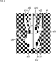
- the labeled Occupancy Map shown in FIG. 4 is generated from the depth data, motion data, and semantic segmentation data generated based on the image and distance information obtained in such an environment.
- the free space where there is no obstacle is white, the unknown area where the obstacle exists or is not certain is gray, and the area where the obstacle exists is black. It is shown.
- regions a31 to a34 corresponding to the other vehicles C1 to C4 among the regions where the obstacles exist have label information indicating that the attribute is a vehicle
- a region corresponding to the motorcycle M1 a35 has label information indicating that the attribute is a motorcycle.
- areas b31 and b32 corresponding to buildings B1 and B2 respectively have label information indicating that the attribute is a building
- areas c31 and c32 corresponding to the street trees W1 and W2 are Each has label information indicating that the attribute is a street tree.
- step S12 the edge extraction unit 25 extracts an edge portion between the non-moving object of the obstacles and the free space from the labeled Occupancy Map.
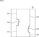
- the edge portion between the obstacle and the free space excluding the regions a31 to a35 having the label information of the moving vehicle or the motorcycle is extracted. Thereby, the edge image shown in FIG. 5 is generated.
- the edge image 40 shown in FIG. 5 has edge areas E41 and E42 which are edge parts of the areas b31 and b32 of the labeled Occupancy Map 30, and edge areas E43 and E44 which are edge parts of the areas c31 and c32.
- the edge areas E41 and E42 have building label information, and the edge areas E43 and E44 have street tree label information.
- the edge image 40 is information indicating the shape of the non-moving object in the labeled Occupancy Map 30 and the attribute of the non-moving object.
- step S13 the position estimation unit 26 acquires data of an edge portion from the prior map expressed by the labeled Occupancy Map.
- step S14 the position estimation unit 26 estimates the self position by matching the data of the generated Occupancy Map with labels with the data of the prior map.
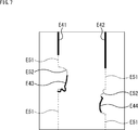
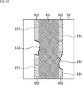
- FIG. 6 is a diagram showing an example of the prior map.
- the pre-map 50 of FIG. 6 is shown as an edge image in which an edge portion between an obstacle (non-moving object) and free space is extracted in the pre-map represented by the labeled Occupancy Map.
- the prior map 50 includes an edge area E51 having label information of a building and an edge area E52 having label information of a street tree.
- the advance map 50 is map data indicating a range sufficiently wider than the range indicated by the labeled Occupancy Map generated while the vehicle is traveling. Therefore, the advance map 50 of FIG. 6 shows data of a specific position in the entire advance map 50 stored in the advance map storage unit 27.
- the position estimation unit 26 matches the shape of the edge area and the label information in the entire pre-map 50 and the edge image 40 of FIG. 5. Then, the position estimation unit 26 takes the position where the degree of coincidence of the shape of the edge area and the label information in the edge image 40 is the highest in the entire pre-map 50 as the self position.
- the position where the information matches is the self position.
- the labeled Occupancy Map can be matched with the prior map without being affected by moving objects such as other vehicles and pedestrians, the self position of the own vehicle can be determined with high accuracy. Is possible.
- free space label information may be further used.
- FIG. 8 shows an example of a labeled Occupancy Map having label information in free space.
- areas d31 and e31 to e33 are further set in the free space (white area) of the labeled Occupancy Map 30 shown in FIG.
- the area d31 has label information indicating that the attribute is a roadway
- the areas e31 to e33 have label information indicating that the attribute is a sidewalk. These label information is based on semantic segmentation.
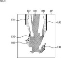
- an edge portion between an obstacle and a free space excluding regions a31 to a35 having label information of a vehicle and a motorcycle as a moving body and a region set as the free space Label information is extracted. Thereby, the edge image shown in FIG. 9 is generated.
- the edge image 40 'shown in FIG. 9 includes regions R41 to R44 in addition to the edge regions similar to the edge image 40 shown in FIG.
- the area R41 corresponds to the area d31 of the labeled Occupancy Map 30 'and has roadway label information.
- the regions R42 to R43 correspond to the regions e31 to e33 of the labeled Occupancy Map 30 ', and have sidewalk label information.
- FIG. 10 shows another example of the prior map.
- the advance map 50 'of FIG. 10 includes, in addition to the same area as the advance map 50 of FIG. 6, an area R51 having roadway label information and an R52 having sidewalk label information.
- the pre-map 50 'of FIG. 10 also shows data for a particular location of the entire pre-map.
- the matching of the shape of the edge area and the label information in the entire pre-map 50 'and the edge image 40' of FIG. 9 is performed to obtain the self position.
- the matching accuracy can be enhanced by further using the label information of the free space in the matching between the labeled Occupancy Map and the prior map, and the self-position of the vehicle can be determined with higher accuracy. It becomes possible.
- the labeled Occupancy Map is a two-dimensional space representing the space around the vehicle, but a plurality of labeled Occupancy Maps in the height direction are generated, and the layer configuration is taken to create the periphery of the vehicle.
- the space of may be expressed in a three-dimensional space.
- the prior map is also configured in the same manner, and matching between layers is performed in matching between the labeled Occupancy Map and the prior map.
- the prior map may indicate the coordinates of the world coordinate system or may indicate the coordinates of the local coordinate system, and is generated by the vehicle traveling in advance by manual driving. Be done.
- Example 1 of advance map generation processing First, with reference to the flowchart in FIG. 11, an example of the world coordinate system advance map generation process will be described.
- the process in FIG. 11 is realized by running a vehicle equipped with a sensor capable of performing RTK-GPS (Real Time Kinematic GPS) positioning in addition to the vehicle control device 10, the camera 11, and the LiDAR 12.
- RTK-GPS Real Time Kinematic GPS
- step S31 the map generation unit 24 generates a labeled Occupancy Map using depth data, RTK-GPS data, and semantic segmentation data.
- the labeled Occupancy Map is generated using RTK-GPS data acquired by a sensor capable of RTK-GPS positioning.
- step S32 the edge extraction unit 25 extracts an edge portion between the non-moving object of the obstacles and the free space from the labeled Occupancy Map. This generates an edge image.
- step S33 the position estimation unit 26 registers the self position converted into the world coordinate system as map data, using the generated edge image and the self position obtained from the RTK-GPS data. Thereby, the position of the host vehicle at that time is stored in the prior map storage unit 27 as a labeled Occupancy Map.
- step S34 the position estimation unit 26 obtains an ideal route for automatic driving, and sets a waypoint on the registered advance map.
- the waypoint referred to here is not information indicating what kind of road is used as a route, but information indicating which lane on a road (road surface) to travel.
- RTK-GPS data is used when generating a labeled Occupancy Map, but position data obtained by other positioning using GNSS (Global Navigation Satellite System) is used. It is also good.
- GNSS Global Navigation Satellite System
- Example 2 of advance map generation processing Next, with reference to the flowchart of FIG. 12, an example of the pre-map generation processing of the local coordinate system will be described.
- the process of FIG. 11 is realized by traveling of a vehicle equipped with the vehicle control device 10, the camera 11, and the LiDAR 12.
- step S51 the map generation unit 24 generates a labeled Occupancy Map using the depth data, the motion data, and the semantic segmentation data.
- the labeled Occupancy Map is generated using the motion data generated by the visual odometry unit 23.
- step S52 the edge extraction unit 25 extracts an edge portion between the non-moving object of the obstacles and the free space from the labeled Occupancy Map. This generates an edge image.
- step S53 the position estimation unit 26 registers, as map data, the self position converted into the local coordinate system using the generated edge image and the relative self position obtained by integrating the motion data. . Thereby, the position of the host vehicle at that time is stored in the prior map storage unit 27 as a labeled Occupancy Map.
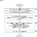
- step S54 the position estimation unit 26 obtains an ideal route for automatic driving, and sets a waypoint on the registered advance map.
- the waypoint can be set based on the alignment of obstacles and roads in the generated advance map.
- the waypoint is set so that the roadside center travels more in the case of the roadside tree.
- the waypoint is set so that the radius of curvature of the route becomes smaller.
- setting of waypoints does not necessarily have to be performed in the advance map generation process, and may be omitted.
- Second embodiment> The automatic driving of the vehicle can be realized based on the waypoint set in the above-described preliminary map generation process. Therefore, in the following, a configuration for performing automatic driving of the vehicle will be described.
- FIG. 13 is a block diagram showing a configuration example of a vehicle control device according to a second embodiment to which the present technology is applied.
- the vehicle control device 60 of FIG. 13 includes a route setting unit 61 and an operation control unit 62 in addition to the same configuration as the vehicle control device 10 of FIG. 1.
- the route setting unit 61 uses the own position estimated by the position estimation unit 26 and the waypoint set in the advance map stored in the advance map storage unit 27 to Set).
- the route setting unit 61 acquires the labeled Occupancy Map from the map generation unit 24, and sets the waypoint in real time, for example, to avoid moving objects. It is also possible to set a travel route.
- the route information indicating the set travel route is supplied to the operation control unit 62.
- the operation control unit 62 controls the operation of the own vehicle so as to travel the traveling route indicated by the route information. Specifically, the operation control unit 62 controls the operation of each driving mechanism, such as a steering mechanism related to steering, a braking device related to braking, an engine related to driving (travelling), and a driving motor, provided in the vehicle.
- each driving mechanism such as a steering mechanism related to steering, a braking device related to braking, an engine related to driving (travelling), and a driving motor, provided in the vehicle.
- the operation control unit 62 controls the illumination of the headlight provided at the front of the vehicle. Specifically, based on the route information indicating the travel route, the operation control unit 62 controls the irradiation angle of the headlights so that the end of the travel route is irradiated with light.
- the operation control unit 62 realizes control of driving assistance (automatic driving) of the vehicle.
- steps S71 to S74 of the flowchart of FIG. 14 are the same as the processes of steps S11 to S14 of the flowchart of FIG.
- the route setting unit 61 refers to the prior map stored in the prior map storage unit 27, and based on the waypoint set in the prior map , Set the travel route of the vehicle.
- the range of the prior map referred to by the route setting unit 61 is, for example, a range including the position used for matching when estimating the self position.
- the route setting unit 61 acquires a labeled Occupancy Map from the map generation unit 24 and sets a waypoint in real time to set a traveling route.
- step S76 the operation control unit 62 controls the automatic driving by controlling the operation of the host vehicle based on the route information indicating the set travel route.
- valet parking can be realized by automatic driving.
- the user travels the vehicle from the entrance of the apartment at home to the parking lot in the neighborhood by manual driving, whereby a pre-map in which the waypoint is set is generated.
- the vehicle is estimated with its own position and the prior map with the waypoint set. It is possible to move to the parking lot automatically based on
- FIG. 15 is a block diagram showing a configuration example of a vehicle control device according to a third embodiment to which the present technology is applied.
- the vehicle control device 70 of FIG. 15 includes a danger degree determination unit 71 in addition to the same configuration as the vehicle control device 60 of FIG. 13.
- the degree-of-risk determination unit 71 determines the degree of risk of the vehicle while traveling based on the image from the camera 11, the depth data from the depth data generation unit 21, and the labeled Occupancy Map from the map generation unit 24.
- the risk level is an index (value) indicating the possibility of occurrence of a dangerous event that may lead to an accident.
- the degree-of-risk determination unit 71 determines that a danger has been detected, and calculates the degree of danger at that point. Then, the degree-of-risk determination unit 71 sets the calculated degree of risk at the point in the advance map stored in the advance map storage unit 27.
- the degree of risk is accumulated for each point on the advance map. Therefore, every time it is determined that a danger is repeatedly detected at the same point, the degree of danger at that point is added and increased.
- the degree-of-risk determination unit 71 corrects the waypoint based on the degree of danger set in the advance map so as to avoid a point with a high degree of danger.
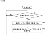
- step S 91 whether the danger level determination unit 71 has detected a danger based on the image from the camera 11, the depth data from the depth data generation unit 21, and the labeled Occupancy Map from the map generation unit 24. Determine
- step S91 The process of step S91 is repeated until it is determined that the danger has been detected. If it is determined that the danger has been detected, the degree-of-risk determination unit 71 calculates the degree of danger at that point, and the process proceeds to step S92.
- step S 92 the degree-of-risk determination unit 71 sets the calculated degree of risk at that point in the advance map stored in the advance map storage unit 27.
- step S93 the degree-of-risk determination unit 71 corrects the waypoint so as to avoid a point with a large degree of risk, based on the degree of risk set in the advance map.
- the degree of risk for a dynamic obstacle is accumulated empirically, and the waypoint is corrected based on the magnitude of the accumulated degree of risk.
- the present technology can be applied to a system that controls a mobile other than a vehicle.
- the present invention can be applied to a vehicle control system as shown in FIG.
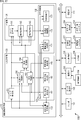
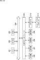
- FIG. 17 is a block diagram showing a configuration example of a schematic function of a vehicle control system 100 which is an example of a mobile control system to which the present technology can be applied.
- the vehicle provided with the vehicle control system 100 is distinguished from other vehicles, it is referred to as the own vehicle or the own vehicle.
- the vehicle control system 100 includes an input unit 101, a data acquisition unit 102, a communication unit 103, an in-vehicle device 104, an output control unit 105, an output unit 106, a drive system control unit 107, a drive system 108, a body system control unit 109, and a body.
- the system system 110, the storage unit 111, and the automatic driving control unit 112 are provided.
- the input unit 101, the data acquisition unit 102, the communication unit 103, the output control unit 105, the drive system control unit 107, the body system control unit 109, the storage unit 111, and the automatic operation control unit 112 are connected via the communication network 121. Connected to each other.
- the communication network 121 may be, for example, an on-vehicle communication network or bus conforming to any standard such as CAN (Controller Area Network), LIN (Local Interconnect Network), LAN (Local Area Network), or FlexRay (registered trademark). Become. In addition, each part of the vehicle control system 100 may be directly connected without passing through the communication network 121.
- CAN Controller Area Network
- LIN Local Interconnect Network
- LAN Local Area Network
- FlexRay registered trademark
- each unit of the vehicle control system 100 performs communication via the communication network 121
- the description of the communication network 121 is omitted.
- the input unit 101 and the automatic driving control unit 112 communicate via the communication network 121, it is described that the input unit 101 and the automatic driving control unit 112 merely communicate.
- the input unit 101 includes an apparatus used by a passenger for inputting various data and instructions.
- the input unit 101 includes operation devices such as a touch panel, a button, a microphone, a switch, and a lever, and an operation device and the like that can be input by a method other than manual operation by voice or gesture.
- the input unit 101 may be a remote control device using infrared rays or other radio waves, or an external connection device such as a mobile device or wearable device corresponding to the operation of the vehicle control system 100.
- the input unit 101 generates an input signal based on data, an instruction, and the like input by the passenger, and supplies the input signal to each unit of the vehicle control system 100.
- the data acquisition unit 102 includes various sensors for acquiring data used for processing of the vehicle control system 100 and supplies the acquired data to each unit of the vehicle control system 100.
- the data acquisition unit 102 includes various sensors for detecting the state of the vehicle.
- the data acquisition unit 102 includes a gyro sensor, an acceleration sensor, an inertia measurement device (IMU), an operation amount of an accelerator pedal, an operation amount of a brake pedal, a steering angle of a steering wheel, and an engine speed.
- IMU inertia measurement device
- a sensor or the like for detecting a motor rotation speed or a rotation speed of a wheel is provided.
- the data acquisition unit 102 includes various sensors for detecting information outside the vehicle.
- the data acquisition unit 102 includes an imaging device such as a ToF (Time Of Flight) camera, a stereo camera, a monocular camera, an infrared camera, and other cameras.
- the data acquisition unit 102 includes an environment sensor for detecting weather, weather or the like, and an ambient information detection sensor for detecting an object around the vehicle.
- the environment sensor includes, for example, a raindrop sensor, a fog sensor, a sunshine sensor, a snow sensor, and the like.
- the ambient information detection sensor is made of, for example, an ultrasonic sensor, a radar, LiDAR (Light Detection and Ranging, Laser Imaging Detection and Ranging), sonar or the like.
- the data acquisition unit 102 includes various sensors for detecting the current position of the vehicle.
- the data acquisition unit 102 includes a GNSS receiver or the like which receives a GNSS signal from a Global Navigation Satellite System (GNSS) satellite.
- GNSS Global Navigation Satellite System
- the data acquisition unit 102 includes various sensors for detecting information in the vehicle.
- the data acquisition unit 102 includes an imaging device for imaging a driver, a biological sensor for detecting biological information of the driver, a microphone for collecting sound in a vehicle interior, and the like.
- the biological sensor is provided, for example, on a seat or a steering wheel, and detects biological information of an occupant sitting on a seat or a driver holding the steering wheel.
- the communication unit 103 communicates with the in-vehicle device 104 and various devices outside the vehicle, a server, a base station, etc., and transmits data supplied from each portion of the vehicle control system 100, and receives the received data. Supply to each part of 100.
- the communication protocol supported by the communication unit 103 is not particularly limited, and the communication unit 103 can also support a plurality of types of communication protocols.
- the communication unit 103 performs wireless communication with the in-vehicle device 104 by wireless LAN, Bluetooth (registered trademark), NFC (Near Field Communication), WUSB (Wireless USB), or the like. Also, for example, the communication unit 103 may use a Universal Serial Bus (USB), a High-Definition Multimedia Interface (HDMI (registered trademark)), or an MHL (Universal Serial Bus) via a connection terminal (and a cable, if necessary) not shown. Wired communication is performed with the in-vehicle device 104 by Mobile High-definition Link) or the like.
- USB Universal Serial Bus
- HDMI High-Definition Multimedia Interface
- MHL Universal Serial Bus
- the communication unit 103 may communicate with an apparatus (for example, an application server or control server) existing on an external network (for example, the Internet, a cloud network, or a network unique to an operator) via a base station or an access point. Communicate. Also, for example, using the P2P (Peer To Peer) technology, the communication unit 103 may use a terminal (eg, a pedestrian or a shop terminal, or an MTC (Machine Type Communication) terminal) with a terminal existing near the host vehicle. Communicate. Furthermore, for example, the communication unit 103 may perform vehicle-to-vehicle communication, vehicle-to-infrastructure communication, vehicle-to-home communication, and vehicle-to-pedestrian communication.
- an apparatus for example, an application server or control server
- an external network for example, the Internet, a cloud network, or a network unique to an operator
- the communication unit 103 may use a terminal (eg, a pedestrian or a shop terminal, or an MTC (Machine Type Communication) terminal)
- V2X communication such as communication is performed.
- the communication unit 103 includes a beacon receiving unit, receives radio waves or electromagnetic waves transmitted from radio stations installed on roads, and acquires information such as current position, traffic jam, traffic restriction, or required time. Do.
- the in-vehicle device 104 includes, for example, a mobile device or wearable device owned by the passenger, an information device carried in or attached to the vehicle, and a navigation device for searching for a route to an arbitrary destination.
- the output control unit 105 controls the output of various information to the passenger of the vehicle or the outside of the vehicle.
- the output control unit 105 generates an output signal including at least one of visual information (for example, image data) and auditory information (for example, audio data), and supplies the generated output signal to the output unit 106.
- the output control unit 105 combines image data captured by different imaging devices of the data acquisition unit 102 to generate an overhead image or a panoramic image, and an output signal including the generated image is generated.
- the output unit 106 is supplied.
- the output control unit 105 generates voice data including a warning sound or a warning message for danger such as collision, contact, entering a danger zone, and the like, and outputs an output signal including the generated voice data to the output unit 106.
- Supply for example, the output control unit 105 generates voice data including a warning sound or a warning message for danger such as collision, contact, entering a danger zone, and the like, and outputs an output signal
- the output unit 106 includes a device capable of outputting visual information or auditory information to the passenger of the vehicle or the outside of the vehicle.
- the output unit 106 includes a display device, an instrument panel, an audio speaker, headphones, wearable devices such as a glasses-type display worn by a passenger, a projector, a lamp, and the like.
- the display device included in the output unit 106 has visual information in the driver's field of vision, such as a head-up display, a transmissive display, and a device having an AR (Augmented Reality) display function, in addition to a device having a normal display. It may be an apparatus for displaying.
- the drive system control unit 107 controls the drive system 108 by generating various control signals and supplying them to the drive system 108. In addition, the drive system control unit 107 supplies a control signal to each unit other than the drive system 108 as necessary, and notifies a control state of the drive system 108, and the like.
- the drive system 108 includes various devices related to the drive system of the vehicle.
- the drive system 108 includes a driving force generating device for generating a driving force of an internal combustion engine or a driving motor, a driving force transmission mechanism for transmitting the driving force to the wheels, and a steering mechanism for adjusting a steering angle.
- a braking system that generates a braking force an antilock brake system (ABS), an electronic stability control (ESC), an electric power steering apparatus, and the like are provided.
- the body control unit 109 controls the body system 110 by generating various control signals and supplying the control signals to the body system 110.
- the body system control unit 109 supplies a control signal to each unit other than the body system 110, as required, to notify the control state of the body system 110, and the like.
- the body system 110 includes various devices of the body system mounted on the vehicle body.
- the body system 110 includes a keyless entry system, a smart key system, a power window device, a power seat, a steering wheel, an air conditioner, and various lamps (for example, headlamps, back lamps, brake lamps, blinkers, fog lamps, etc.) Etc.
- the storage unit 111 includes, for example, a read only memory (ROM), a random access memory (RAM), a magnetic storage device such as a hard disk drive (HDD), a semiconductor storage device, an optical storage device, and a magneto-optical storage device. .
- the storage unit 111 stores various programs, data, and the like used by each unit of the vehicle control system 100.
- the storage unit 111 is map data such as a three-dimensional high-precision map such as a dynamic map, a global map that covers a wide area with lower accuracy than a high-precision map, and information around the vehicle.
- map data such as a three-dimensional high-precision map such as a dynamic map, a global map that covers a wide area with lower accuracy than a high-precision map, and information around the vehicle.
- the autonomous driving control unit 112 performs control regarding autonomous driving such as autonomous traveling or driving assistance. Specifically, for example, the automatic driving control unit 112 can avoid collision or reduce impact of the vehicle, follow-up traveling based on the distance between vehicles, vehicle speed maintenance traveling, collision warning of the vehicle, lane departure warning of the vehicle, etc. Coordinated control is carried out to realize the functions of the Advanced Driver Assistance System (ADAS), including: Further, for example, the automatic driving control unit 112 performs cooperative control for the purpose of automatic driving or the like that travels autonomously without depending on the driver's operation.
- the automatic driving control unit 112 includes a detection unit 131, a self position estimation unit 132, a situation analysis unit 133, a planning unit 134, and an operation control unit 135.
- the detection unit 131 detects various types of information necessary for control of automatic driving.
- the detection unit 131 includes an out-of-vehicle information detection unit 141, an in-vehicle information detection unit 142, and a vehicle state detection unit 143.
- the external information detection unit 141 performs detection processing of external information of the vehicle based on data or signals from each unit of the vehicle control system 100. For example, the external information detection unit 141 performs detection processing of an object around the host vehicle, recognition processing, tracking processing, and detection processing of the distance to the object.
- the objects to be detected include, for example, vehicles, people, obstacles, structures, roads, traffic lights, traffic signs, road markings and the like.
- the outside-of-vehicle information detection unit 141 performs a process of detecting the environment around the vehicle.
- the surrounding environment to be detected includes, for example, weather, temperature, humidity, brightness, road surface condition and the like.
- the information outside the vehicle detection unit 141 indicates data indicating the result of the detection process as the self position estimation unit 132, the map analysis unit 151 of the situation analysis unit 133, the traffic rule recognition unit 152, the situation recognition unit 153, and the operation control unit 135. Supply to the emergency situation avoidance unit 171 and the like.
- the out-of-vehicle information detection unit 141 corresponds to the depth data generation unit 21, the semantic segmentation unit 22, and the visual odometry unit 23 described above, and generates depth data, motion data, and semantic segmentation data.
- the in-vehicle information detection unit 142 performs in-vehicle information detection processing based on data or signals from each unit of the vehicle control system 100.
- the in-vehicle information detection unit 142 performs a driver authentication process and recognition process, a driver state detection process, a passenger detection process, an in-vehicle environment detection process, and the like.
- the state of the driver to be detected includes, for example, physical condition, awakening degree, concentration degree, fatigue degree, gaze direction and the like.
- the in-vehicle environment to be detected includes, for example, temperature, humidity, brightness, smell and the like.
- the in-vehicle information detection unit 142 supplies data indicating the result of the detection process to the situation recognition unit 153 of the situation analysis unit 133, the emergency situation avoidance unit 171 of the operation control unit 135, and the like.
- the vehicle state detection unit 143 detects the state of the vehicle based on data or signals from each unit of the vehicle control system 100.
- the state of the vehicle to be detected includes, for example, speed, acceleration, steering angle, presence / absence of abnormality and contents, state of driving operation, position and inclination of power seat, state of door lock, and other in-vehicle devices. Status etc. are included.
- the vehicle state detection unit 143 supplies data indicating the result of the detection process to the situation recognition unit 153 of the situation analysis unit 133, the emergency situation avoidance unit 171 of the operation control unit 135, and the like.
- the self position estimation unit 132 estimates the position and orientation of the vehicle based on data or signals from each part of the vehicle control system 100 such as the external information detection unit 141 and the situation recognition unit 153 of the situation analysis unit 133. Do the processing. In addition, the self position estimation unit 132 generates a local map (hereinafter, referred to as a self position estimation map) used to estimate the self position, as necessary.
- the self-location estimation map is, for example, a high-accuracy map using a technique such as SLAM (Simultaneous Localization and Mapping).
- the self position estimation unit 132 supplies data indicating the result of the estimation process to the map analysis unit 151, the traffic rule recognition unit 152, the situation recognition unit 153, and the like of the situation analysis unit 133. In addition, the self position estimation unit 132 stores the self position estimation map in the storage unit 111.
- the self position estimation unit 132 corresponds to the edge extraction unit 25 and the position estimation unit 26 described above, and estimates the self position by matching the attribute-added occupancy grid map (labeled Occupancy Map) with the prior map.
- the situation analysis unit 133 analyzes the situation of the vehicle and the surroundings.
- the situation analysis unit 133 includes a map analysis unit 151, a traffic rule recognition unit 152, a situation recognition unit 153, and a situation prediction unit 154.
- the map analysis unit 151 uses various data or signals stored in the storage unit 111 while using data or signals from each part of the vehicle control system 100 such as the self position estimation unit 132 and the external information detection unit 141 as necessary. Perform analysis processing and construct a map that contains information necessary for automatic driving processing.
- the map analysis unit 151 is configured of the traffic rule recognition unit 152, the situation recognition unit 153, the situation prediction unit 154, the route planning unit 161 of the planning unit 134, the action planning unit 162, the operation planning unit 163, and the like. Supply to
- the traffic rule recognition unit 152 uses traffic rules around the vehicle based on data or signals from each unit of the vehicle control system 100 such as the self position estimation unit 132, the outside information detection unit 141, and the map analysis unit 151. Perform recognition processing. By this recognition process, for example, the position and state of signals around the vehicle, the contents of traffic restriction around the vehicle, and the travelable lane are recognized.
- the traffic rule recognition unit 152 supplies data indicating the result of the recognition process to the situation prediction unit 154 and the like.
- the situation recognition unit 153 uses data or signals from each unit of the vehicle control system 100 such as the self position estimation unit 132, the outside information detection unit 141, the in-vehicle information detection unit 142, the vehicle state detection unit 143, and the map analysis unit 151. Based on the recognition processing of the situation regarding the vehicle. For example, the situation recognition unit 153 performs recognition processing of the situation of the own vehicle, the situation around the own vehicle, the situation of the driver of the own vehicle, and the like. In addition, the situation recognition unit 153 generates a local map (hereinafter referred to as a situation recognition map) used to recognize the situation around the host vehicle, as necessary.
- the situation recognition map is, for example, an Occupancy Grid Map.
- the situation of the vehicle to be recognized includes, for example, the position, posture, movement (for example, speed, acceleration, moving direction, etc.) of the vehicle, and the presence or absence and contents of abnormality.
- the situation around the vehicle to be recognized includes, for example, the type and position of the surrounding stationary object, the type, position and movement of the surrounding moving object (eg, speed, acceleration, movement direction, etc.) Configuration and road surface conditions, as well as ambient weather, temperature, humidity, brightness, etc. are included.
- the state of the driver to be recognized includes, for example, physical condition, alertness level, concentration level, fatigue level, movement of eyes, driving operation and the like.
- the situation recognition unit 153 supplies data (including a situation recognition map, if necessary) indicating the result of the recognition process to the self position estimation unit 132, the situation prediction unit 154, and the like. In addition, the situation recognition unit 153 stores the situation recognition map in the storage unit 111.
- the situation recognition unit 153 corresponds to the map generation unit 24 and the risk degree determination unit 71 described above, and generates a labeled Occupancy Map or determines the degree of risk.
- the situation prediction unit 154 performs prediction processing of the situation regarding the own vehicle based on data or signals from each part of the vehicle control system 100 such as the map analysis unit 151, the traffic rule recognition unit 152, and the situation recognition unit 153. For example, the situation prediction unit 154 performs prediction processing of the situation of the vehicle, the situation around the vehicle, the situation of the driver, and the like.
- the situation of the subject vehicle to be predicted includes, for example, the behavior of the subject vehicle, the occurrence of an abnormality, the travelable distance, and the like.
- the situation around the vehicle to be predicted includes, for example, the behavior of the moving object around the vehicle, the change of the signal state, and the change of the environment such as the weather.
- the driver's condition to be predicted includes, for example, the driver's behavior and physical condition.
- the situation prediction unit 154 together with data from the traffic rule recognition unit 152 and the situation recognition unit 153, indicates data indicating the result of the prediction process, the route planning unit 161 of the planning unit 134, the action planning unit 162, and the operation planning unit 163. Supply to etc.
- the route planning unit 161 plans a route to a destination based on data or signals from each unit of the vehicle control system 100 such as the map analysis unit 151 and the situation prediction unit 154. For example, the route planning unit 161 sets a route from the current position to the specified destination based on the global map. In addition, for example, the route planning unit 161 changes the route as appropriate based on traffic jams, accidents, traffic restrictions, conditions such as construction, the physical condition of the driver, and the like. The route planning unit 161 supplies data indicating the planned route to the action planning unit 162 and the like.
- the action planning part 162 Based on data or signals from each part of the vehicle control system 100 such as the map analyzing part 151 and the situation predicting part 154, the action planning part 162 safely makes the route planned by the route planning part 161 within the planned time. Plan your vehicle's action to drive. For example, the action planning unit 162 performs planning of start, stop, traveling direction (for example, forward, backward, left turn, right turn, change of direction, etc.), travel lane, travel speed, overtaking, and the like. The action planning unit 162 supplies data indicating the planned behavior of the host vehicle to the operation planning unit 163 and the like.
- the operation planning unit 163 is an operation of the own vehicle for realizing the action planned by the action planning unit 162 based on data or signals from each unit of the vehicle control system 100 such as the map analysis unit 151 and the situation prediction unit 154. Plan.
- the operation plan unit 163 plans acceleration, deceleration, a traveling track, and the like.
- the operation planning unit 163 supplies data indicating the planned operation of the vehicle to the acceleration / deceleration control unit 172, the direction control unit 173, and the like of the operation control unit 135.
- the operation control unit 135 controls the operation of the vehicle.
- the operation control unit 135 includes an emergency situation avoidance unit 171, an acceleration / deceleration control unit 172, and a direction control unit 173.
- the emergency situation avoidance unit 171 is based on the detection results of the external information detection unit 141, the in-vehicle information detection unit 142, and the vehicle state detection unit 143, collision, contact, entry into a danger zone, driver's abnormality, vehicle Perform detection processing of an emergency such as an abnormality.
- the emergency situation avoidance unit 171 detects the occurrence of an emergency situation, it plans the operation of the own vehicle for avoiding an emergency situation such as a sudden stop or a sudden turn.
- the emergency situation avoidance unit 171 supplies data indicating the planned operation of the host vehicle to the acceleration / deceleration control unit 172, the direction control unit 173, and the like.
- the acceleration / deceleration control unit 172 performs acceleration / deceleration control for realizing the operation of the own vehicle planned by the operation planning unit 163 or the emergency situation avoidance unit 171. For example, the acceleration / deceleration control unit 172 calculates a control target value of a driving force generator or a braking device for achieving planned acceleration, deceleration, or sudden stop, and drives a control command indicating the calculated control target value. It is supplied to the system control unit 107.
- the direction control unit 173 performs direction control for realizing the operation of the vehicle planned by the operation planning unit 163 or the emergency situation avoidance unit 171. For example, the direction control unit 173 calculates the control target value of the steering mechanism for realizing the traveling track or the sharp turn planned by the operation plan unit 163 or the emergency situation avoidance unit 171, and performs control indicating the calculated control target value. The command is supplied to the drive system control unit 107.
- the series of processes described above can be performed by hardware or software.
- a program that configures the software is installed on a computer.
- the computer includes, for example, a general-purpose personal computer that can execute various functions by installing a computer incorporated in dedicated hardware and various programs.
- FIG. 18 is a block diagram showing an example of a hardware configuration of a computer that executes the series of processes described above according to a program.
- a CPU 201 In the computer, a CPU 201, a read only memory (ROM) 202, and a random access memory (RAM) 203 are mutually connected by a bus 204.
- ROM read only memory
- RAM random access memory
- an input / output interface 205 is connected to the bus 204.
- An input unit 206, an output unit 207, a storage unit 208, a communication unit 209, and a drive 910 are connected to the input / output interface 205.
- the input unit 206 includes a keyboard, a mouse, a microphone and the like.
- the output unit 207 includes a display, a speaker, and the like.
- the storage unit 208 includes a hard disk, a non-volatile memory, and the like.
- the communication unit 209 is configured of a network interface or the like.
- the drive 210 drives removable media 211 such as a magnetic disk, an optical disk, a magneto-optical disk, or a semiconductor memory.
- the CPU 201 loads the program stored in the storage unit 208 into the RAM 203 via the input / output interface 205 and the bus 204 and executes the program. Processing is performed.
- the program executed by the computer (CPU 201) can be provided by being recorded on, for example, the removable medium 211 as a package medium or the like. Also, the program can be provided via a wired or wireless transmission medium such as a local area network, the Internet, or digital satellite broadcasting.
- the program can be installed in the storage unit 208 via the input / output interface 205 by attaching the removable media 211 to the drive 210.
- the program can be received by the communication unit 209 via a wired or wireless transmission medium and installed in the storage unit 208.
- the program can be installed in advance in the ROM 202 or the storage unit 208.
- the program executed by the computer may be a program that performs processing in chronological order according to the order described in this specification, in parallel, or when necessary, such as when a call is made. It may be a program to be processed.
- the present technology can have a cloud computing configuration in which one function is shared and processed by a plurality of devices via a network.
- each step described in the above-described flowchart can be executed by one device or in a shared manner by a plurality of devices.
- the plurality of processes included in one step can be executed by being shared by a plurality of devices in addition to being executed by one device.
- the present technology can be configured as follows.
- a map generation unit for generating an attributed occupancy grid map in which the attributes of the obstacle are labeled on an occupied grid map having the existence probability of the obstacle in the space around the moving object for each grid;
- a position estimation unit for estimating the position of the moving object by matching the shape of the non-moving object and the attribute in the attribute-included occupied lattice map and the advance map which is the attribute-provided occupied lattice map prepared in advance Information processing apparatus provided.
- an edge extraction unit that generates an edge image by extracting an edge portion between the non-moving object and the free space without the obstacle in the attributed occupancy lattice map.
- the position estimation unit estimates the position of the moving body by filtering the position information obtained as a result of the matching based on motion data of the moving body.
- the position estimation unit estimates the position of the moving object using a Kalman filter.
- a route setting unit for setting a moving route of the moving object based on the estimated position of the moving object and the waypoint set in the advance map.
- (1) to (5) The information processing apparatus according to claim 1.
- the information processing apparatus according to (6) further including: an operation control unit configured to control an operation of the moving body based on the set moving path of the moving body.
- the information processing apparatus according to any one of (6) to (8), wherein the degree-of-risk determination unit sets the degree of risk at a position at which the degree of risk is calculated in the advance map. (10) The information processing apparatus according to (9), wherein the degree-of-risk determination unit corrects the waypoint registered in the preliminary map based on the magnitude of the degree of risk set in the preliminary map.
- the information processing apparatus Generating an attributed occupancy grid map in which the attributes of the obstacle are labeled, in an occupancy grid map having a presence probability of an obstacle in a space around the mobile body for each grid, An information processing method for estimating the position of the moving object by matching the shape of the non-moving object and the attribute in the attribute-included occupied lattice map and the advance map which is the attribute-added occupied lattice map prepared in advance.
Abstract
The present technology pertains to an information processing device, an information processing method, and a program with which it is possible to find a host position of a moving body with high precision. A map generation unit generates an attribute-provided occupancy grid map in which attributes of obstacles are labeled on an occupancy grid map having, in each grid, the probability that an obstacle is present in a space around a moving body; and a position estimation unit estimates the position of the moving body by matching the shape and attributes of a non-moving body in the attribute-provided occupancy grid map and an in-advance map, which is an attribute-provided occupancy grid map that is prepared in advance. The present technology can be applied to on-board vehicle control systems.
Description
本技術は、情報処理装置、情報処理方法、およびプログラムに関し、特に、移動体の自己位置を高精度に求めることができるようにした情報処理装置、情報処理方法、およびプログラムに関する。
The present technology relates to an information processing apparatus, an information processing method, and a program, and more particularly, to an information processing apparatus, an information processing method, and a program that can obtain the self position of a moving object with high accuracy.
近年、車両やロボットなどの、自律移動する移動体の自己位置を求めるための様々な手法が提案されている。
In recent years, various methods have been proposed for determining the self position of a mobile object that moves autonomously, such as a vehicle or a robot.
例えば、特許文献1には、平らな壁面や一定の高さの障害物などの、移動体周囲における環境構造を用いることで、移動体の自己位置を推定する手法が開示されている。
For example, Patent Document 1 discloses a method of estimating the self position of a moving object by using an environmental structure around the moving object, such as a flat wall surface or an obstacle with a certain height.
しかしながら、特許文献1の手法においては、環境構造の形状を利用して移動体の自己位置を推定しているため、似たような形状の環境構造が存在する場所では、自己位置を誤る可能性があった。
However, in the method of Patent Document 1, since the self-position of the moving body is estimated using the shape of the environmental structure, the possibility of mistaking the self-position in the place where the similar-shaped environmental structure exists was there.
本技術は、このような状況に鑑みてなされたものであり、移動体の自己位置を高精度に求めることができるようにするものである。
The present technology has been made in view of such a situation, and makes it possible to obtain the self position of the mobile object with high accuracy.
本技術の一側面の情報処理装置は、移動体の周囲の空間における障害物の存在確率を格子毎に有する占有格子地図に、前記障害物の属性がラベリングされた属性付き占有格子地図を生成するマップ生成部と、前記属性付き占有格子地図と、あらかじめ用意された前記属性付き占有格子地図である事前地図とにおける、非動体の形状および前記属性についてのマッチングにより、前記移動体の位置を推定する位置推定部とを備える。
An information processing apparatus according to one aspect of the present technology generates an attributed occupancy grid map in which an attribute of the obstacle is labeled on an occupancy grid map that has an existence probability of an obstacle in a space around a mobile body for each grid. The position of the moving object is estimated by matching the shape of the non-moving object and the attribute in the map generation unit, the attribute-included occupied lattice map, and the advance map which is the attribute-provided occupied lattice map prepared in advance And a position estimation unit.
本技術の一側面の情報処理方法は、情報処理装置が、移動体の周囲の空間における障害物の存在確率を格子毎に有する占有格子地図に、前記障害物の属性がラベリングされた属性付き占有格子地図を生成し、前記属性付き占有格子地図と、あらかじめ用意された前記属性付き占有格子地図である事前地図とにおける、非動体の形状および前記属性のマッチングにより、前記移動体の位置を推定する情報処理方法である。
In an information processing method according to one aspect of the present technology, an attribute-occupied occupancy in which an attribute of the obstacle is labeled in an occupied grid map in which the information processing apparatus has an existence probability of an obstacle in a space around a mobile body for each grid. A grid map is generated, and the position of the moving body is estimated by matching the shape of the non-moving body and the attribute in the attribute-occupied exclusive grid map and the pre-map which is the attribute-provided occupied grid map prepared in advance. It is an information processing method.
本技術の一側面のプログラムは、コンピュータに、移動体の周囲の空間における障害物の存在確率を格子毎に有する占有格子地図に、前記障害物の属性がラベリングされた属性付き占有格子地図を生成し、前記属性付き占有格子地図と、あらかじめ用意された前記属性付き占有格子地図である事前地図とにおける、非動体の形状および前記属性のマッチングにより、前記移動体の位置を推定する処理を実行させるプログラムである。
A program according to one aspect of the present technology generates, on a computer, an attributed occupancy grid map in which the attributes of the obstacle are labeled on an occupancy grid map having the presence probability of the obstacle in the space around the mobile body for each grid. Processing of estimating the position of the moving object by matching the shape of the non-moving object and the attribute in the attribute-added occupied lattice map and the advance map which is the attribute-provided occupied lattice map prepared in advance It is a program.
本技術の一側面においては、移動体の周囲の空間における障害物の存在確率を格子毎に有する占有格子地図に、前記障害物の属性がラベリングされた属性付き占有格子地図が生成され、前記属性付き占有格子地図と、あらかじめ用意された前記属性付き占有格子地図である事前地図とにおける、非動体の形状および前記属性のマッチングにより、前記移動体の位置が推定される。
In an aspect of the present technology, an attribute occupied grid map in which the attributes of the obstacle are labeled is generated on an occupied grid map having a probability of existence of an obstacle in a space around the mobile object for each grid. The position of the moving object is estimated by matching the shape of the non-moving object and the attribute in the attached occupied lattice map and the advance map which is the attributeed occupied lattice map prepared in advance.
本技術の一側面によれば、移動体の自己位置を高精度に求めることが可能となる。
According to one aspect of the present technology, it is possible to determine the self position of the mobile object with high accuracy.
以下、本開示を実施するための形態(以下、実施の形態とする)について説明する。なお、説明は以下の順序で行う。
Hereinafter, modes for carrying out the present disclosure (hereinafter, referred to as embodiments) will be described. The description will be made in the following order.
1.第1の実施の形態(自己位置を推定する構成)
2.事前マップの生成方法
3.第2の実施の形態(自動運転を行う構成)
4.第3の実施の形態(ウェイポイントを修正する構成)
5.移動体制御システムの例
6.その他 1. First embodiment (configuration for estimating self position)
2. Method of generating advance map 3. Second embodiment (configuration for performing automatic operation)
4. Third embodiment (configuration for correcting waypoints)
5. Example of mobile control system 6. Other
<1.第1の実施の形態>
(車両制御装置の構成例)
図1は、本技術を適用した第1の実施の形態の車両制御装置の構成例を示すブロック図である。 <1. First embodiment>
(Example of configuration of vehicle control device)
FIG. 1 is a block diagram illustrating a configuration example of a vehicle control device according to a first embodiment to which the present technology is applied.
(車両制御装置の構成例)
図1は、本技術を適用した第1の実施の形態の車両制御装置の構成例を示すブロック図である。 <1. First embodiment>
(Example of configuration of vehicle control device)
FIG. 1 is a block diagram illustrating a configuration example of a vehicle control device according to a first embodiment to which the present technology is applied.
図1の車両制御装置10は、自動車などの車両に搭載され、いわゆる電子制御装置(ECU)などの一部として構成される。車両制御装置10は、車両に搭載されたカメラ11やLiDAR(Light Detection and Ranging,Laser Imaging Detection and Ranging)12からの信号に基づいて、車両の位置を推定する。
The vehicle control device 10 of FIG. 1 is mounted on a vehicle such as a car and configured as a part of a so-called electronic control unit (ECU) or the like. The vehicle control device 10 estimates the position of the vehicle based on signals from a camera 11 mounted on the vehicle and a light detection and ranging (LiDAR) 12.
カメラ11は、CMOS(Complementary Metal Oxide Semiconductor)イメージセンサやCCD(Charge Coupled Device)イメージセンサなどの固体撮像素子を備え、車両の前方を撮像する。撮像された画像は車両制御装置10に出力される。
The camera 11 includes a solid-state imaging device such as a complementary metal oxide semiconductor (CMOS) image sensor or a charge coupled device (CCD) image sensor, and captures an image in front of the vehicle. The captured image is output to the vehicle control device 10.
LiDAR12は、ToF(Time of Flight)方式を利用して、車両の前方にレーザ光を投光し、障害物で反射した反射光を受光することで、車両の前方にある障害物までの距離を測定する。測定結果として得られた距離情報は車両制御装置10に出力される。
The LiDAR 12 emits laser light to the front of the vehicle using the ToF (Time of Flight) method, and receives the reflected light reflected by the obstacle to determine the distance to the obstacle in front of the vehicle. taking measurement. The distance information obtained as the measurement result is output to the vehicle control device 10.
なお、カメラ11をステレオカメラとして構成することで、カメラ11が取得した車両の前方の奥行き方向の情報を距離情報として、車両制御装置10に出力されるようにしてもよい。この場合、LiDAR12を省略することができる。
Note that by configuring the camera 11 as a stereo camera, the information in the depth direction in front of the vehicle acquired by the camera 11 may be output to the vehicle control device 10 as distance information. In this case, LiDAR 12 can be omitted.
次に、車両制御装置10の詳細な構成について説明する。
Next, the detailed configuration of the vehicle control device 10 will be described.
車両制御装置10は、デプスデータ生成部21、セマンティックセグメンテーション部22、ビジュアルオドメトリ部23、マップ生成部24、エッジ抽出部25、位置推定部26、および事前マップ記憶部27を備える。
The vehicle control device 10 includes a depth data generation unit 21, a semantic segmentation unit 22, a visual odometry unit 23, a map generation unit 24, an edge extraction unit 25, a position estimation unit 26, and a prior map storage unit 27.
デプスデータ生成部21は、カメラ11からの画像と、LiDAR12(またはカメラ11)からの距離情報に基づいて、カメラ11の撮像範囲内にある障害物までの距離を示すデプスデータ(距離画像)を生成する。生成されたデプスデータは、マップ生成部24に供給される。
The depth data generation unit 21 performs depth data (distance image) indicating the distance to an obstacle within the imaging range of the camera 11 based on the image from the camera 11 and the distance information from the LiDAR 12 (or the camera 11). Generate The generated depth data is supplied to the map generation unit 24.
セマンティックセグメンテーション部22は、ディープラーニングなどの機械学習によるセマンティックセグメンテーションにより、カメラ11からの画像について、画素単位で被写体の属性を判定し、各画素に対してその属性をラベリングする。
The semantic segmentation unit 22 determines the attribute of the subject on a pixel basis for the image from the camera 11 by semantic segmentation by machine learning such as deep learning, and labels the attribute for each pixel.
被写体の属性としては、例えば、自車両の周囲の空間に存在する他の車両(他車両)、バイク、自転車、人(歩行者)、ビルなどの建物、街路樹、信号機、電柱などがある。被写体の属性がラベリングされた画像データは、セマンティックセグメンテーションデータとして、マップ生成部24に供給される。
The attributes of the subject include, for example, other vehicles (other vehicles) existing in the space around the host vehicle, bikes, bicycles, people (pedestrians), buildings such as buildings, trees in the street, traffic lights, telephone poles, and the like. The image data labeled with the attribute of the subject is supplied to the map generation unit 24 as semantic segmentation data.
ビジュアルオドメトリ部23は、カメラ11からの画像について、フレーム間の差分に基づいて、画像上の特徴点の座標の変位を検知することにより、移動している自車両の速度、位置、および方向を算出する。算出された速度、位置、方向を示す運動データは、マップ生成部24に供給される。
The visual odometry unit 23 detects the displacement of the coordinates of the feature point on the image from the camera 11 based on the difference between the frames, thereby determining the speed, position, and direction of the moving vehicle. calculate. Motion data indicating the calculated velocity, position, and direction is supplied to the map generation unit 24.
マップ生成部24は、デプスデータ生成部21、セマンティックセグメンテーション部22、およびビジュアルオドメトリ部23からの各データを用いて、属性付き占有格子地図を生成し、エッジ抽出部25に供給する。属性付き占有格子地図は、自車両の周囲の空間における障害物の存在確率を格子毎に有する占有格子地図(Occupancy Grid Map)に、その障害物の属性がラベリングされたデータである。
The map generation unit 24 generates an attribute-added occupied lattice map using each data from the depth data generation unit 21, the semantic segmentation unit 22, and the visual odometry unit 23, and supplies the generated occupancy lattice map to the edge extraction unit 25. The attributed occupancy grid map is data in which an attribute of the obstacle is labeled in an occupancy grid map (Occupancy Grid Map) having the existence probability of the obstacle in the space around the host vehicle for each grid.
占有格子地図においては、自車両を基準とする一定の範囲内の領域が、格子状に複数のセルに分割され、各セルに障害物が存在するか否かを示す値が設定される。これにより、占有格子地図は、障害物が存在する領域、障害物が存在しないフリースペース、障害物が存在するか定かではない未知の領域に区分される。
In the occupied grid map, a region within a certain range based on the host vehicle is divided into a plurality of cells in a grid, and a value indicating whether or not an obstacle exists in each cell is set. As a result, the occupied grid map is divided into an area in which the obstacle is present, a free space in which the obstacle is not present, and an unknown area in which the obstacle is unknown.
そして、属性付き占有格子地図においては、占有格子地図の障害物が存在する領域に、セマンティックセグメンテーションデータに基づいた属性が付与される。
Then, in the attribute-added occupied lattice map, an attribute based on the semantic segmentation data is given to the area where the obstacle of the occupied lattice map is present.
このようにして得られた属性付き占有格子地図を、以下においては、ラベル付きOccupancy Mapという。
The attribute-occupied occupancy lattice map thus obtained is hereinafter referred to as a labeled Occupancy Map.
エッジ抽出部25は、マップ生成部24からのラベル付きOccupancy Mapにおいて、障害物のうちの非動体とフリースペースとの間のエッジ部分を抽出する。
The edge extraction unit 25 extracts an edge portion between the non-moving object of the obstacles and the free space in the labeled Occupancy Map from the map generation unit 24.
ここでいう非動体は、ビルなどの建物、街路樹、信号機、電柱といった通常移動することのない障害物をいう。したがって、ラベル付きOccupancy Mapにおいて、移動する可能性のある他車両、バイク、自転車、人などの動体の属性が付与された障害物は考慮されなくなる。
Here, non-moving objects refer to obstacles that do not normally move, such as buildings such as buildings, road trees, traffic lights, and telephone poles. Therefore, in the labeled Occupancy Map, obstacles to which the attribute of moving objects such as other vehicles, bikes, bicycles, people, etc. that may move can not be taken into consideration.
エッジ部分が抽出されたラベル付きOccupancy Map(以下、エッジ画像という)は、位置推定部26に供給される。
The labeled Occupancy Map (hereinafter referred to as an edge image) from which the edge portion is extracted is supplied to the position estimation unit 26.
位置推定部26は、ラベル付きOccupancy Mapと、事前マップ記憶部27に記憶されている事前マップ(事前地図)とにおける、非動体の形状および属性についてのマッチングにより、自車両の位置(自己位置)を推定する。事前マップは、あらかじめ用意されたラベル付きOccupancy Mapであり、世界座標系の座標を示すものであってもよいし、ローカル座標系の座標を示すものであってもよい。事前マップは、地図データを提供するベンダなどによって生成されたり、車両自体が事前に走行することで生成されたりする。
The position estimation unit 26 matches the position and position of the non-moving object in the labeled Occupancy Map and the advance map (advanced map) stored in the advance map storage unit 27 to find the position of the vehicle (self position). Estimate The preliminary map is a labeled Occupancy Map prepared in advance, which may indicate the coordinates of the world coordinate system or may indicate the coordinates of the local coordinate system. The advance map is generated by a vendor who provides map data or the vehicle itself travels in advance.
具体的には、位置推定部26は、エッジ抽出部25からのエッジ画像と、事前マップ記憶部27に記憶されている事前マップにおける非動体とフリースペースとの間のエッジ部分とにおける、非動体の形状および属性についてのマッチングを行う。マッチングを行うことにより、緯度と経度を表す位置情報、さらには車両の姿勢を表す姿勢情報が得られる。
Specifically, the position estimation unit 26 determines the non-moving object in the edge image from the edge extracting unit 25 and the edge portion between the non-moving object and the free space in the advance map stored in the advance map storage unit 27. Perform matching on the shape and attributes of By performing matching, position information indicating latitude and longitude, and attitude information indicating the attitude of the vehicle can be obtained.
また、位置推定部26は、マッチングの結果として得られた位置情報を、ビジュアルオドメトリ部23からの運動データに基づいてフィルタリングする。ここでは、例えばカルマンフィルタを用いることで、自己位置を予測した予測結果と、得られた位置情報とを比較し、重み付け加算する処理が行われる。また、パーティクルフィルタを用いた処理が行われるようにしてもよい。この場合、ビジュアルオドメトリ部23により算出された速度の予測結果を用いて、パーティクルフィルタの各パーティクルの位置を更新し、各位置における事前マップとのマッチング結果を尤度としてパーティクルを生成し、最終的な位置を求める処理が行われる。
Further, the position estimation unit 26 filters the position information obtained as a result of the matching based on the motion data from the visual odometry unit 23. Here, for example, by using a Kalman filter, a process of comparing the obtained prediction result obtained by predicting the self position and the obtained position information is performed. Further, processing using a particle filter may be performed. In this case, the position of each particle of the particle filter is updated using the prediction result of the velocity calculated by the visual odometry unit 23, and the particle is generated with the matching result with the prior map at each position as the likelihood. A process is performed to obtain a proper position.
(自己位置推定処理)
次に、図2のフローチャートを参照して、車両制御装置10により実行される自己位置推定処理について説明する。図2の処理は、車両の走行中、カメラ11からの画像が車両制御装置10に出力されることで実行される。 (Self position estimation process)
Next, the self-position estimation process executed by thevehicle control device 10 will be described with reference to the flowchart of FIG. The process of FIG. 2 is executed by outputting an image from the camera 11 to the vehicle control device 10 while the vehicle is traveling.
次に、図2のフローチャートを参照して、車両制御装置10により実行される自己位置推定処理について説明する。図2の処理は、車両の走行中、カメラ11からの画像が車両制御装置10に出力されることで実行される。 (Self position estimation process)
Next, the self-position estimation process executed by the
なお、図2の処理は、カメラ11による撮像のフレームレートと同期して繰り返し実行されてもよいし、所定のフレーム数を周期として繰り返し実行されてもよい。
Note that the process of FIG. 2 may be repeatedly performed in synchronization with a frame rate of imaging by the camera 11, or may be repeatedly performed with a predetermined number of frames as a cycle.
ステップS11において、マップ生成部24は、デプスデータ、運動データ、およびセマンティックセグメンテーションデータを用いて、ラベル付きOccupancy Mapを生成する。
In step S11, the map generation unit 24 generates a labeled Occupancy Map using depth data, motion data, and semantic segmentation data.
デプスデータ、運動データ、およびセマンティックセグメンテーションデータは、それぞれデプスデータ生成部21、ビジュアルオドメトリ部23、およびセマンティックセグメンテーション部22により生成され、マップ生成部24に供給される。
The depth data, motion data, and semantic segmentation data are generated by the depth data generation unit 21, the visual odometry unit 23, and the semantic segmentation unit 22, respectively, and supplied to the map generation unit 24.
図3は、あるタイミングでの走行中の車両の周囲の環境の例を示す図である。
FIG. 3 is a diagram showing an example of the environment around a vehicle traveling at a certain timing.
図3上側には、自車両C0を含む自車両C0の進行方向の環境を示す鳥瞰図が、図3下側には、自車両C0から見た進行方向の環境を示す正面図が示されている。つまり、図3上側の鳥瞰図においては、図中上方向が、自車両C0の進行方向となり、図3下側の正面図においては、図中奥行き方向が、自車両C0の進行方向となる。
A bird's-eye view showing the environment in the traveling direction of the vehicle C0 including the vehicle C0 is shown on the upper side in FIG. 3, and a front view showing the environment in the traveling direction seen from the vehicle C0 is shown on the lower side in FIG. . That is, in the bird's-eye view on the upper side of FIG. 3, the upper direction in the drawing is the traveling direction of the host vehicle C0, and in the front view on the lower side of FIG. 3, the depth direction in the drawing is the traveling direction of the host vehicle C0.
図3の例では、自車両C0の前方には、2台の他車両C1,C2が走行しており、そのさらに前方には、2台の他車両C3,C4と、バイクM1が走行している。自車両C0が走行する道路の左側には、建物B1が建ち、街路樹W1が植えられている。また、自車両C0が走行する道路の右側には、建物B2が建ち、街路樹W2が植えられている。
In the example of FIG. 3, two other vehicles C1 and C2 are traveling ahead of the host vehicle C0, and two other vehicles C3 and C4 and a motorcycle M1 are traveling ahead of that. There is. A building B1 is built on the left side of the road where the host vehicle C0 travels, and a road tree W1 is planted. In addition, a building B2 is built on the right side of the road on which the host vehicle C0 travels, and a road tree W2 is planted.
このような環境において得られた画像と距離情報に基づいて生成されたデプスデータ、運動データ、およびセマンティックセグメンテーションデータにより、図4に示されるラベル付きOccupancy Mapが生成される。
The labeled Occupancy Map shown in FIG. 4 is generated from the depth data, motion data, and semantic segmentation data generated based on the image and distance information obtained in such an environment.
図4に示されるラベル付きOccupancy Map30においては、障害物が存在しないフリースペースは白色で、障害物が存在するか定かではない未知の領域は灰色で、障害物が存在する領域は黒色で、それぞれ示されている。
In the labeled Occupancy Map 30 shown in FIG. 4, the free space where there is no obstacle is white, the unknown area where the obstacle exists or is not certain is gray, and the area where the obstacle exists is black. It is shown.
ラベル付きOccupancy Map30において、障害物が存在する領域のうち、他車両C1乃至C4に対応する領域a31乃至a34は、それぞれ属性が車両であることを示すラベル情報を有し、バイクM1に対応する領域a35は、属性がバイクであることを示すラベル情報を有している。
In the labeled Occupancy Map 30, regions a31 to a34 corresponding to the other vehicles C1 to C4 among the regions where the obstacles exist have label information indicating that the attribute is a vehicle, and a region corresponding to the motorcycle M1 a35 has label information indicating that the attribute is a motorcycle.
また、ラベル付きOccupancy Map30において、建物B1,B2に対応する領域b31,b32は、それぞれ属性が建物であることを示すラベル情報を有し、街路樹W1,W2に対応する領域c31,c32は、それぞれ属性が街路樹であることを示すラベル情報を有している。
In the labeled Occupancy Map 30, areas b31 and b32 corresponding to buildings B1 and B2 respectively have label information indicating that the attribute is a building, and areas c31 and c32 corresponding to the street trees W1 and W2 are Each has label information indicating that the attribute is a street tree.
図2のフローチャートに戻り、ステップS12において、エッジ抽出部25は、ラベル付きOccupancy Mapから、障害物のうちの非動体とフリースペースとの間のエッジ部分を抽出する。
Returning to the flowchart of FIG. 2, in step S12, the edge extraction unit 25 extracts an edge portion between the non-moving object of the obstacles and the free space from the labeled Occupancy Map.
すなわち、図4のラベル付きOccupancy Map30において、動体である車両またはバイクのラベル情報を有する領域a31乃至a35を除いた障害物とフリースペースとの間のエッジ部分が抽出される。これにより、図5に示されるエッジ画像が生成される。
That is, in the labeled Occupancy Map 30 of FIG. 4, the edge portion between the obstacle and the free space excluding the regions a31 to a35 having the label information of the moving vehicle or the motorcycle is extracted. Thereby, the edge image shown in FIG. 5 is generated.
図5に示されるエッジ画像40は、ラベル付きOccupancy Map30の領域b31,b32のエッジ部分であるエッジ領域E41,E42と、領域c31,c32のエッジ部分であるエッジ領域E43,E44を有する。エッジ領域E41,E42は、建物のラベル情報を有し、エッジ領域E43,E44は、街路樹のラベル情報を有している。
The edge image 40 shown in FIG. 5 has edge areas E41 and E42 which are edge parts of the areas b31 and b32 of the labeled Occupancy Map 30, and edge areas E43 and E44 which are edge parts of the areas c31 and c32. The edge areas E41 and E42 have building label information, and the edge areas E43 and E44 have street tree label information.
すなわち、エッジ画像40は、ラベル付きOccupancy Map30における非動体の形状、および、その非動体の属性を示す情報となる。
That is, the edge image 40 is information indicating the shape of the non-moving object in the labeled Occupancy Map 30 and the attribute of the non-moving object.
図2のフローチャートに戻り、ステップS13において、位置推定部26は、ラベル付きOccupancy Mapで表現された事前マップから、エッジ部分のデータを取得する。
Returning to the flowchart of FIG. 2, in step S13, the position estimation unit 26 acquires data of an edge portion from the prior map expressed by the labeled Occupancy Map.
そして、ステップS14において、位置推定部26は、生成したラベル付きOccupancy Mapと事前マップのデータのマッチングを行うことで、自己位置を推定する。
Then, in step S14, the position estimation unit 26 estimates the self position by matching the data of the generated Occupancy Map with labels with the data of the prior map.
図6は、事前マップの例を示す図である。
FIG. 6 is a diagram showing an example of the prior map.
図6の事前マップ50は、ラベル付きOccupancy Mapで表現された事前マップにおいて、障害物(非動体)とフリースペースとの間のエッジ部分が抽出されたエッジ画像として示される。事前マップ50は、建物のラベル情報を有するエッジ領域E51と、街路樹のラベル情報を有するエッジ領域E52を有している。
The pre-map 50 of FIG. 6 is shown as an edge image in which an edge portion between an obstacle (non-moving object) and free space is extracted in the pre-map represented by the labeled Occupancy Map. The prior map 50 includes an edge area E51 having label information of a building and an edge area E52 having label information of a street tree.
事前マップ50は、車両の走行中に生成されるラベル付きOccupancy Mapが示す範囲よりも十分に広い範囲を示す地図データである。したがって、図6の事前マップ50は、事前マップ記憶部27に記憶されている事前マップ50全体のうちの特定の位置のデータを示すものである。
The advance map 50 is map data indicating a range sufficiently wider than the range indicated by the labeled Occupancy Map generated while the vehicle is traveling. Therefore, the advance map 50 of FIG. 6 shows data of a specific position in the entire advance map 50 stored in the advance map storage unit 27.
位置推定部26は、事前マップ50全体と、図5のエッジ画像40における、エッジ領域の形状およびラベル情報のマッチングを行う。そして、位置推定部26は、事前マップ50全体で、エッジ画像40におけるエッジ領域の形状およびラベル情報の一致度が最も高くなる位置を、自己位置とする。
The position estimation unit 26 matches the shape of the edge area and the label information in the entire pre-map 50 and the edge image 40 of FIG. 5. Then, the position estimation unit 26 takes the position where the degree of coincidence of the shape of the edge area and the label information in the edge image 40 is the highest in the entire pre-map 50 as the self position.
具体的には、図7に示されるように、事前マップ50全体において、エッジ画像40のエッジ領域E41,E42とエッジ領域E51、エッジ画像40のエッジ領域E43,E44とエッジ領域E52の形状およびラベル情報が一致する位置が、自己位置となる。
Specifically, as shown in FIG. 7, the shapes and labels of the edge areas E41 and E42 and the edge area E51 of the edge image 40 and the edge areas E43 and E44 and the edge area E52 of the edge image 40 in the entire premap 50. The position where the information matches is the self position.
以上の処理によれば、他車両や歩行者などの動体の影響を受けることなく、ラベル付きOccupancy Mapと事前マップとのマッチングを行うことができるので、自車両の自己位置を高精度に求めることが可能となる。
According to the above processing, since the labeled Occupancy Map can be matched with the prior map without being affected by moving objects such as other vehicles and pedestrians, the self position of the own vehicle can be determined with high accuracy. Is possible.
(マッチングの他の例)
上述したラベル付きOccupancy Mapと事前マップとのマッチングにおいて、フリースペースのラベル情報をさらに用いるようにしてもよい。 (Other examples of matching)
In the matching between the labeled Occupancy Map and the prior map, free space label information may be further used.
上述したラベル付きOccupancy Mapと事前マップとのマッチングにおいて、フリースペースのラベル情報をさらに用いるようにしてもよい。 (Other examples of matching)
In the matching between the labeled Occupancy Map and the prior map, free space label information may be further used.
図8は、フリースペースにラベル情報を有するラベル付きOccupancy Mapの例を示している。
FIG. 8 shows an example of a labeled Occupancy Map having label information in free space.
図8に示されるラベル付きOccupancy Map30’においては、図4に示されるラベル付きOccupancy Map30のフリースペース(白色領域)に、領域d31,e31乃至e33がさらに設定されている。領域d31は、属性が車道であることを示すラベル情報を有し、領域e31乃至e33は、それぞれ属性が歩道であることを示すラベル情報を有している。これらのラベル情報は、セマンティックセグメンテーションに基づくものである。
In the labeled Occupancy Map 30 'shown in FIG. 8, areas d31 and e31 to e33 are further set in the free space (white area) of the labeled Occupancy Map 30 shown in FIG. The area d31 has label information indicating that the attribute is a roadway, and the areas e31 to e33 have label information indicating that the attribute is a sidewalk. These label information is based on semantic segmentation.
図8のラベル付きOccupancy Map30’においては、動体である車両とバイクのラベル情報を有する領域a31乃至a35を除いた障害物とフリースペースとの間のエッジ部分と、フリースペースに設定されている領域が有するラベル情報が抽出される。これにより、図9に示されるエッジ画像が生成される。
In the labeled Occupancy Map 30 'of FIG. 8, an edge portion between an obstacle and a free space excluding regions a31 to a35 having label information of a vehicle and a motorcycle as a moving body and a region set as the free space Label information is extracted. Thereby, the edge image shown in FIG. 9 is generated.
図9に示されるエッジ画像40’は、図5に示されるエッジ画像40と同様のエッジ領域に加え、領域R41乃至R44を有している。領域R41は、ラベル付きOccupancy Map30’の領域d31に対応し、車道のラベル情報を有している。領域R42乃至R43は、ラベル付きOccupancy Map30’の領域e31乃至e33に対応し、歩道のラベル情報を有している。
The edge image 40 'shown in FIG. 9 includes regions R41 to R44 in addition to the edge regions similar to the edge image 40 shown in FIG. The area R41 corresponds to the area d31 of the labeled Occupancy Map 30 'and has roadway label information. The regions R42 to R43 correspond to the regions e31 to e33 of the labeled Occupancy Map 30 ', and have sidewalk label information.
図10は、事前マップの他の例を示している。
FIG. 10 shows another example of the prior map.
図10の事前マップ50’は、図6の事前マップ50と同様の領域に加え、車道のラベル情報を有する領域R51と、歩道のラベル情報を有するR52を有している。図10の事前マップ50’もまた、事前マップ全体のうちの特定の位置のデータを示すものである。
The advance map 50 'of FIG. 10 includes, in addition to the same area as the advance map 50 of FIG. 6, an area R51 having roadway label information and an R52 having sidewalk label information. The pre-map 50 'of FIG. 10 also shows data for a particular location of the entire pre-map.
そして、事前マップ50’全体と、図9のエッジ画像40’における、エッジ領域の形状およびラベル情報のマッチングが行われることで、自己位置が求められる。
Then, the matching of the shape of the edge area and the label information in the entire pre-map 50 'and the edge image 40' of FIG. 9 is performed to obtain the self position.
このようにして、ラベル付きOccupancy Mapと事前マップとのマッチングにおいて、フリースペースのラベル情報をさらに用いることで、マッチングの精度を高めることができ、自車両の自己位置をより高精度に求めることが可能となる。
In this way, the matching accuracy can be enhanced by further using the label information of the free space in the matching between the labeled Occupancy Map and the prior map, and the self-position of the vehicle can be determined with higher accuracy. It becomes possible.
また、ラベル付きOccupancy Mapは、車両の周囲の空間を2次元空間で表現したものであるが、高さ方向についての複数のラベル付きOccupancy Mapを生成し、レイヤ構成を採ることで、車両の周囲の空間を3次元空間で表現するようにしてもよい。この場合、事前マップも同様の構成を採るようにし、ラベル付きOccupancy Mapと事前マップとのマッチングにおいては、レイヤ毎のマッチングが行われるようにする。
In addition, the labeled Occupancy Map is a two-dimensional space representing the space around the vehicle, but a plurality of labeled Occupancy Maps in the height direction are generated, and the layer configuration is taken to create the periphery of the vehicle. The space of may be expressed in a three-dimensional space. In this case, the prior map is also configured in the same manner, and matching between layers is performed in matching between the labeled Occupancy Map and the prior map.
<2.事前マップの生成方法>
ここで、事前マップの生成方法について説明する。 <2. How to generate advance map>
Here, a method of generating the prior map will be described.
ここで、事前マップの生成方法について説明する。 <2. How to generate advance map>
Here, a method of generating the prior map will be described.
上述したように、事前マップは、世界座標系の座標を示すものであってもよいし、ローカル座標系の座標を示すものであってもよく、手動運転により車両が事前に走行することで生成される。
As described above, the prior map may indicate the coordinates of the world coordinate system or may indicate the coordinates of the local coordinate system, and is generated by the vehicle traveling in advance by manual driving. Be done.
(事前マップ生成処理の例1)
まず、図11のフローチャートを参照して、世界座標系の事前マップ生成処理の例について説明する。図11の処理は、車両制御装置10、カメラ11、およびLiDAR12に加え、RTK-GPS(Real Time Kinematic GPS)測位が可能なセンサが搭載された車両が走行することで実現される。 (Example 1 of advance map generation processing)
First, with reference to the flowchart in FIG. 11, an example of the world coordinate system advance map generation process will be described. The process in FIG. 11 is realized by running a vehicle equipped with a sensor capable of performing RTK-GPS (Real Time Kinematic GPS) positioning in addition to thevehicle control device 10, the camera 11, and the LiDAR 12.
まず、図11のフローチャートを参照して、世界座標系の事前マップ生成処理の例について説明する。図11の処理は、車両制御装置10、カメラ11、およびLiDAR12に加え、RTK-GPS(Real Time Kinematic GPS)測位が可能なセンサが搭載された車両が走行することで実現される。 (Example 1 of advance map generation processing)
First, with reference to the flowchart in FIG. 11, an example of the world coordinate system advance map generation process will be described. The process in FIG. 11 is realized by running a vehicle equipped with a sensor capable of performing RTK-GPS (Real Time Kinematic GPS) positioning in addition to the
ステップS31において、マップ生成部24は、デプスデータ、RTK-GPSデータ、およびセマンティックセグメンテーションデータを用いて、ラベル付きOccupancy Mapを生成する。
In step S31, the map generation unit 24 generates a labeled Occupancy Map using depth data, RTK-GPS data, and semantic segmentation data.
ここでは、ビジュアルオドメトリ部23により生成される運動データに代えて、RTK-GPS測位が可能なセンサにより取得されたRTK-GPSデータを用いて、ラベル付きOccupancy Mapが生成される。
Here, instead of the motion data generated by the visual odometry unit 23, the labeled Occupancy Map is generated using RTK-GPS data acquired by a sensor capable of RTK-GPS positioning.
ステップS32において、エッジ抽出部25は、ラベル付きOccupancy Mapから、障害物のうちの非動体とフリースペースとの間のエッジ部分を抽出する。これにより、エッジ画像が生成される。
In step S32, the edge extraction unit 25 extracts an edge portion between the non-moving object of the obstacles and the free space from the labeled Occupancy Map. This generates an edge image.
ステップS33において、位置推定部26は、生成されたエッジ画像と、RTK-GPSデータから得られる自己位置を用いて、世界座標系に変換した自己位置を、地図データとして登録する。これにより、事前マップ記憶部27には、そのときの自車両の位置が、ラベル付きOccupancy Mapとして記憶される。
In step S33, the position estimation unit 26 registers the self position converted into the world coordinate system as map data, using the generated edge image and the self position obtained from the RTK-GPS data. Thereby, the position of the host vehicle at that time is stored in the prior map storage unit 27 as a labeled Occupancy Map.
さらに、ステップS34において、位置推定部26は、自動運転のための理想的な経路を求め、登録した事前マップ上にウェイポイントを設定する。
Further, in step S34, the position estimation unit 26 obtains an ideal route for automatic driving, and sets a waypoint on the registered advance map.
ここでいうウェイポイントは、どのような道路を経路とするかを示す情報ではなく、道路(路面)上のどのレーンを走行するかなどを示す情報である。
The waypoint referred to here is not information indicating what kind of road is used as a route, but information indicating which lane on a road (road surface) to travel.
以上の処理により、動体の影響を受けない世界座標系の事前マップを生成することができる。
By the above processing, it is possible to generate a prior map of the world coordinate system which is not influenced by the moving body.
なお、以上においては、ラベル付きOccupancy Mapを生成する際、RTK-GPSデータを用いるようにしたが、GNSS(Global Navigation Satellite System)を利用した他の測位によって得られた位置データを用いるようにしてもよい。
In the above, RTK-GPS data is used when generating a labeled Occupancy Map, but position data obtained by other positioning using GNSS (Global Navigation Satellite System) is used. It is also good.
(事前マップ生成処理の例2)
次に、図12のフローチャートを参照して、ローカル座標系の事前マップ生成処理の例について説明する。図11の処理は、車両制御装置10、カメラ11、およびLiDAR12が搭載された車両が走行することで実現される。 (Example 2 of advance map generation processing)
Next, with reference to the flowchart of FIG. 12, an example of the pre-map generation processing of the local coordinate system will be described. The process of FIG. 11 is realized by traveling of a vehicle equipped with thevehicle control device 10, the camera 11, and the LiDAR 12.
次に、図12のフローチャートを参照して、ローカル座標系の事前マップ生成処理の例について説明する。図11の処理は、車両制御装置10、カメラ11、およびLiDAR12が搭載された車両が走行することで実現される。 (Example 2 of advance map generation processing)
Next, with reference to the flowchart of FIG. 12, an example of the pre-map generation processing of the local coordinate system will be described. The process of FIG. 11 is realized by traveling of a vehicle equipped with the
ステップS51において、マップ生成部24は、デプスデータ、運動データ、およびセマンティックセグメンテーションデータを用いて、ラベル付きOccupancy Mapを生成する。
In step S51, the map generation unit 24 generates a labeled Occupancy Map using the depth data, the motion data, and the semantic segmentation data.
ここでは、ビジュアルオドメトリ部23により生成される運動データを用いて、ラベル付きOccupancy Mapが生成される。
Here, the labeled Occupancy Map is generated using the motion data generated by the visual odometry unit 23.
ステップS52において、エッジ抽出部25は、ラベル付きOccupancy Mapから、障害物のうちの非動体とフリースペースとの間のエッジ部分を抽出する。これにより、エッジ画像が生成される。
In step S52, the edge extraction unit 25 extracts an edge portion between the non-moving object of the obstacles and the free space from the labeled Occupancy Map. This generates an edge image.
ステップS53において、位置推定部26は、生成されたエッジ画像と、運動データを積分して得られた相対的な自己位置を用いて、ローカル座標系に変換した自己位置を、地図データとして登録する。これにより、事前マップ記憶部27には、そのときの自車両の位置が、ラベル付きOccupancy Mapとして記憶される。
In step S53, the position estimation unit 26 registers, as map data, the self position converted into the local coordinate system using the generated edge image and the relative self position obtained by integrating the motion data. . Thereby, the position of the host vehicle at that time is stored in the prior map storage unit 27 as a labeled Occupancy Map.
さらに、ステップS54において、位置推定部26は、自動運転のための理想的な経路を求め、登録した事前マップ上にウェイポイントを設定する。
Furthermore, in step S54, the position estimation unit 26 obtains an ideal route for automatic driving, and sets a waypoint on the registered advance map.
以上の処理により、動体の影響を受けないローカル座標系の事前マップを生成することができる。
By the above processing, it is possible to generate a prior map of the local coordinate system which is not affected by the moving object.
上述した処理において、ウェイポイントは、生成した事前マップにおける障害物や道路の線形に基づいて設定されるようにすることができる。
In the process described above, the waypoint can be set based on the alignment of obstacles and roads in the generated advance map.
例えば、道路脇にある障害物が電柱の場合と、街路樹の場合とでは、街路樹の場合の方が、より道路中央寄りを走行するように、ウェイポイントが設定されるようにする。また、道路がカーブしている場合には、経路の曲率半径がより小さくなるように、ウェイポイントが設定されるようにする。
For example, in the case where the obstacle at the side of the road is a telephone pole and in the case of a roadside tree, the waypoint is set so that the roadside center travels more in the case of the roadside tree. In addition, when the road is curved, the waypoint is set so that the radius of curvature of the route becomes smaller.
なお、事前マップ生成処理において、ウェイポイントの設定は必ずしも行われる必要はなく、省略するようにしてもよい。
Note that setting of waypoints does not necessarily have to be performed in the advance map generation process, and may be omitted.
<3.第2の実施の形態>
上述した事前マップ生成処理において設定されたウェイポイントに基づいて、車両の自動運転を実現することができる。そこで、以下においては、車両の自動運転を行う構成について説明する。 <3. Second embodiment>
The automatic driving of the vehicle can be realized based on the waypoint set in the above-described preliminary map generation process. Therefore, in the following, a configuration for performing automatic driving of the vehicle will be described.
(車両制御装置の構成例)
図13は、本技術を適用した第2の実施の形態の車両制御装置の構成例を示すブロック図である。 (Example of configuration of vehicle control device)
FIG. 13 is a block diagram showing a configuration example of a vehicle control device according to a second embodiment to which the present technology is applied.
図13は、本技術を適用した第2の実施の形態の車両制御装置の構成例を示すブロック図である。 (Example of configuration of vehicle control device)
FIG. 13 is a block diagram showing a configuration example of a vehicle control device according to a second embodiment to which the present technology is applied.
図13の車両制御装置60は、図1の車両制御装置10と同様の構成に加え、経路設定部61と動作制御部62を備える。
The vehicle control device 60 of FIG. 13 includes a route setting unit 61 and an operation control unit 62 in addition to the same configuration as the vehicle control device 10 of FIG. 1.
経路設定部61は、位置推定部26により推定された自己位置と、事前マップ記憶部27に記憶されている事前マップに設定されているウェイポイントとを用いて、自車両の走行経路(移動経路)を設定する。
The route setting unit 61 uses the own position estimated by the position estimation unit 26 and the waypoint set in the advance map stored in the advance map storage unit 27 to Set).
また、事前マップにウェイポイントが設定されていない場合には、経路設定部61は、マップ生成部24からラベル付きOccupancy Mapを取得し、例えば動体を避けるように、リアルタイムでウェイポイントを設定することで、走行経路を設定することもできる。
In addition, when the waypoint is not set in the advance map, the route setting unit 61 acquires the labeled Occupancy Map from the map generation unit 24, and sets the waypoint in real time, for example, to avoid moving objects. It is also possible to set a travel route.
設定された走行経路を示す経路情報は、動作制御部62に供給される。
The route information indicating the set travel route is supplied to the operation control unit 62.
動作制御部62は、経路設定部61からの経路情報に基づいて、その経路情報で示される走行経路を走行するよう、自車両の動作を制御する。具体的には、動作制御部62は、車両が備える、操舵に関わるステアリング機構、制動に関わる制動装置、駆動(走行)に関わるエンジンや駆動モータといった各運転機構の動作を制御する。
Based on the route information from the route setting unit 61, the operation control unit 62 controls the operation of the own vehicle so as to travel the traveling route indicated by the route information. Specifically, the operation control unit 62 controls the operation of each driving mechanism, such as a steering mechanism related to steering, a braking device related to braking, an engine related to driving (travelling), and a driving motor, provided in the vehicle.
さらに、動作制御部62は、車両の前部に設けられるヘッドライトの照射を制御する。具体的には、動作制御部62は、走行経路を示す経路情報に基づいて、走行経路の先が光で照射されるように、ヘッドライトの照射角度を制御する。
Furthermore, the operation control unit 62 controls the illumination of the headlight provided at the front of the vehicle. Specifically, based on the route information indicating the travel route, the operation control unit 62 controls the irradiation angle of the headlights so that the end of the travel route is irradiated with light.
このようにして、動作制御部62により、車両の運転支援(自動運転)の制御が実現される。
Thus, the operation control unit 62 realizes control of driving assistance (automatic driving) of the vehicle.
(自動運転制御処理)
次に、図14のフローチャートを参照して、車両制御装置60により実行される自動運転制御処理について説明する。 (Automatic operation control process)
Next, an automatic driving control process executed by thevehicle control device 60 will be described with reference to the flowchart of FIG.
次に、図14のフローチャートを参照して、車両制御装置60により実行される自動運転制御処理について説明する。 (Automatic operation control process)
Next, an automatic driving control process executed by the
なお、図14のフローチャートのステップS71乃至S74の処理は、図2のフローチャートのステップS11乃至S14の処理と同様であるので、その説明は省略する。
The processes of steps S71 to S74 of the flowchart of FIG. 14 are the same as the processes of steps S11 to S14 of the flowchart of FIG.
ステップS74において自己位置が推定された後、ステップS75において、経路設定部61は、事前マップ記憶部27に記憶されている事前マップを参照し、その事前マップに設定されているウェイポイントに基づいて、自車両の走行経路を設定する。
After the self position is estimated in step S74, in step S75, the route setting unit 61 refers to the prior map stored in the prior map storage unit 27, and based on the waypoint set in the prior map , Set the travel route of the vehicle.
経路設定部61により参照される事前マップの範囲は、例えば、自己位置の推定の際にマッチングに用いられた位置を含む範囲などとされる。
The range of the prior map referred to by the route setting unit 61 is, for example, a range including the position used for matching when estimating the self position.
なお、事前マップにウェイポイントが設定されていない場合、経路設定部61は、マップ生成部24からラベル付きOccupancy Mapを取得し、リアルタイムでウェイポイントを設定することで、走行経路を設定する。
When a waypoint is not set in the advance map, the route setting unit 61 acquires a labeled Occupancy Map from the map generation unit 24 and sets a waypoint in real time to set a traveling route.
ステップS76において、動作制御部62は、設定された走行経路を示す経路情報に基づいて、自車両の動作を制御することで、自動運転を制御する。
In step S76, the operation control unit 62 controls the automatic driving by controlling the operation of the host vehicle based on the route information indicating the set travel route.
以上のようにして、車両の自動運転を実現することができる。
As described above, automatic driving of the vehicle can be realized.
例えば、手動運転により一度走行した経路について、事前マップを生成するとともに、ウェイポイントを設定することで、それ以降は、自己位置を推定しながら、目的地まで自動で車両を走行させることが可能となる。
For example, it is possible to automatically drive the vehicle to the destination while estimating its own position by generating a map in advance and setting a waypoint for the route once traveled by manual operation. Become.
これにより、例えば、自動運転によるバレーパーキングを実現することができる。
Thereby, for example, valet parking can be realized by automatic driving.
まず、ユーザが、自宅のマンションのエントランスから近所の駐車場までの行程を、手動運転により車両を走行させることで、ウェイポイントが設定された事前マップが生成される。
First, the user travels the vehicle from the entrance of the apartment at home to the parking lot in the neighborhood by manual driving, whereby a pre-map in which the waypoint is set is generated.
その後は、ユーザが、外出先から自宅のマンションのエントランスまで手動運転により車両を走行させ、車両を降りた場合であっても、車両は、自己位置の推定とウェイポイントが設定された事前マップとに基づいて、自動で駐車場まで移動することが可能となる。
After that, even when the user manually drives the vehicle from the outside to the entrance of the apartment at home and gets off the vehicle, the vehicle is estimated with its own position and the prior map with the waypoint set. It is possible to move to the parking lot automatically based on
<4.第3の実施の形態>
上述した車両の自動運転により、事故につながるような危険な事象が発生するおそれのある箇所を走行する可能性がある。そこで、以下においては、危険を避けるようにウェイポイントの修正を行う構成について説明する。 <4. Third embodiment>
With the above-described automatic driving of the vehicle, there is a possibility of traveling at a place where a dangerous event that may lead to an accident may occur. Therefore, in the following, a configuration will be described in which waypoint correction is performed so as to avoid danger.
(車両制御装置の構成例)
図15は、本技術を適用した第3の実施の形態の車両制御装置の構成例を示すブロック図である。 (Example of configuration of vehicle control device)
FIG. 15 is a block diagram showing a configuration example of a vehicle control device according to a third embodiment to which the present technology is applied.
図15は、本技術を適用した第3の実施の形態の車両制御装置の構成例を示すブロック図である。 (Example of configuration of vehicle control device)
FIG. 15 is a block diagram showing a configuration example of a vehicle control device according to a third embodiment to which the present technology is applied.
図15の車両制御装置70は、図13の車両制御装置60と同様の構成に加え、危険度判定部71を備える。
The vehicle control device 70 of FIG. 15 includes a danger degree determination unit 71 in addition to the same configuration as the vehicle control device 60 of FIG. 13.
危険度判定部71は、カメラ11からの画像、デプスデータ生成部21からのデプスデータ、および、マップ生成部24からのラベル付きOccupancy Mapに基づいて、走行中の車両の危険度を判定する。危険度は、事故につながるような危険な事象が発生する可能性を示す指標(値)とされる。
The degree-of-risk determination unit 71 determines the degree of risk of the vehicle while traveling based on the image from the camera 11, the depth data from the depth data generation unit 21, and the labeled Occupancy Map from the map generation unit 24. The risk level is an index (value) indicating the possibility of occurrence of a dangerous event that may lead to an accident.
例えば、カメラ11の撮像範囲内で、電柱の陰から子供が飛び出してきた場合、デプスデータにおいて、急激に距離情報が小さくなる領域が検知されたり、ラベル付きOccupancy Mapにおいて、障害物(動体)の動きの急激な変化が検知される。
For example, when a child jumps out from behind a telephone pole within the imaging range of the camera 11, an area in which distance information decreases sharply in depth data is detected or an obstacle (moving object) is detected in a labeled Occupancy Map. Sudden changes in movement are detected.
このような場合、危険度判定部71は、危険を察知したと判定し、その地点での危険度を算出する。そして、危険度判定部71は、事前マップ記憶部27に記憶されている事前マップにおけるその地点に、算出した危険度を設定する。
In such a case, the degree-of-risk determination unit 71 determines that a danger has been detected, and calculates the degree of danger at that point. Then, the degree-of-risk determination unit 71 sets the calculated degree of risk at the point in the advance map stored in the advance map storage unit 27.
危険度は、事前マップ上の地点ごとに累積される。したがって、同一の地点で繰り返し危険を察知したと判定される度に、その地点での危険度は加算され大きくなる。
The degree of risk is accumulated for each point on the advance map. Therefore, every time it is determined that a danger is repeatedly detected at the same point, the degree of danger at that point is added and increased.
そして、危険度判定部71は、事前マップにウェイポイントが設定されている場合、事前マップに設定された危険度に基づいて、危険度の大きい地点を避けるように、ウェイポイントを修正する。
Then, when the waypoint is set in the advance map, the degree-of-risk determination unit 71 corrects the waypoint based on the degree of danger set in the advance map so as to avoid a point with a high degree of danger.
(ウェイポイント修正処理)
次に、図16のフローチャートを参照して、車両制御装置70により実行されるウェイポイント修正処理について説明する。図16の処理は、車両の走行中(例えば自動運転中など)に実行される。また、ここでは、事前マップ記憶部27に記憶されている事前マップにウェイポイントが設定されているものとする。 (Waypoint correction process)
Next, the waypoint correction process executed by thevehicle control device 70 will be described with reference to the flowchart of FIG. The process of FIG. 16 is performed while the vehicle is traveling (for example, during automatic driving). Also, here, it is assumed that waypoints are set in the advance map stored in the advance map storage unit 27.
次に、図16のフローチャートを参照して、車両制御装置70により実行されるウェイポイント修正処理について説明する。図16の処理は、車両の走行中(例えば自動運転中など)に実行される。また、ここでは、事前マップ記憶部27に記憶されている事前マップにウェイポイントが設定されているものとする。 (Waypoint correction process)
Next, the waypoint correction process executed by the
ステップS91において、危険度判定部71は、カメラ11からの画像、デプスデータ生成部21からのデプスデータ、および、マップ生成部24からのラベル付きOccupancy Mapに基づいて、危険を察知したか否かを判定する。
In step S 91, whether the danger level determination unit 71 has detected a danger based on the image from the camera 11, the depth data from the depth data generation unit 21, and the labeled Occupancy Map from the map generation unit 24. Determine
ステップS91の処理は、危険を察知したと判定されるまで繰り返される。危険を察知したと判定されると、危険度判定部71は、その地点での危険度を算出し、処理はステップS92に進む。
The process of step S91 is repeated until it is determined that the danger has been detected. If it is determined that the danger has been detected, the degree-of-risk determination unit 71 calculates the degree of danger at that point, and the process proceeds to step S92.
ステップS92において、危険度判定部71は、事前マップ記憶部27に記憶されている事前マップにおけるその地点に、算出した危険度を設定する。
In step S 92, the degree-of-risk determination unit 71 sets the calculated degree of risk at that point in the advance map stored in the advance map storage unit 27.
そして、ステップS93において、危険度判定部71は、事前マップに設定された危険度に基づいて、危険度の大きい地点を避けるように、ウェイポイントを修正する。
Then, in step S93, the degree-of-risk determination unit 71 corrects the waypoint so as to avoid a point with a large degree of risk, based on the degree of risk set in the advance map.
以上の処理によれば、動的な障害物についての危険度が経験的に累積され、累積された危険度の大きさに基づいて、ウェイポイントが修正される。これにより、自動運転において、事故につながるような危険な事象が発生するおそれのある箇所を避けて走行することが可能となる。
According to the above processing, the degree of risk for a dynamic obstacle is accumulated empirically, and the waypoint is corrected based on the magnitude of the accumulated degree of risk. Thereby, in the automatic driving, it is possible to travel while avoiding a place where a dangerous event which may lead to an accident may occur.
<5.移動体制御システムの例>
本技術は、車両以外の移動体を制御するシステムに適用することができる。例えば、図17に示されるような車両制御システムにも適用することができる。 <5. Mobile Control System Example>
The present technology can be applied to a system that controls a mobile other than a vehicle. For example, the present invention can be applied to a vehicle control system as shown in FIG.
本技術は、車両以外の移動体を制御するシステムに適用することができる。例えば、図17に示されるような車両制御システムにも適用することができる。 <5. Mobile Control System Example>
The present technology can be applied to a system that controls a mobile other than a vehicle. For example, the present invention can be applied to a vehicle control system as shown in FIG.
図17は、本技術が適用され得る移動体制御システムの一例である車両制御システム100の概略的な機能の構成例を示すブロック図である。
FIG. 17 is a block diagram showing a configuration example of a schematic function of a vehicle control system 100 which is an example of a mobile control system to which the present technology can be applied.
なお、以下、車両制御システム100が設けられている車両を他の車両と区別する場合、自車又は自車両と称する。
Hereinafter, when the vehicle provided with the vehicle control system 100 is distinguished from other vehicles, it is referred to as the own vehicle or the own vehicle.
車両制御システム100は、入力部101、データ取得部102、通信部103、車内機器104、出力制御部105、出力部106、駆動系制御部107、駆動系システム108、ボディ系制御部109、ボディ系システム110、記憶部111、及び、自動運転制御部112を備える。入力部101、データ取得部102、通信部103、出力制御部105、駆動系制御部107、ボディ系制御部109、記憶部111、及び、自動運転制御部112は、通信ネットワーク121を介して、相互に接続されている。通信ネットワーク121は、例えば、CAN(Controller Area Network)、LIN(Local Interconnect Network)、LAN(Local Area Network)、又は、FlexRay(登録商標)等の任意の規格に準拠した車載通信ネットワークやバス等からなる。なお、車両制御システム100の各部は、通信ネットワーク121を介さずに、直接接続される場合もある。
The vehicle control system 100 includes an input unit 101, a data acquisition unit 102, a communication unit 103, an in-vehicle device 104, an output control unit 105, an output unit 106, a drive system control unit 107, a drive system 108, a body system control unit 109, and a body. The system system 110, the storage unit 111, and the automatic driving control unit 112 are provided. The input unit 101, the data acquisition unit 102, the communication unit 103, the output control unit 105, the drive system control unit 107, the body system control unit 109, the storage unit 111, and the automatic operation control unit 112 are connected via the communication network 121. Connected to each other. The communication network 121 may be, for example, an on-vehicle communication network or bus conforming to any standard such as CAN (Controller Area Network), LIN (Local Interconnect Network), LAN (Local Area Network), or FlexRay (registered trademark). Become. In addition, each part of the vehicle control system 100 may be directly connected without passing through the communication network 121.
なお、以下、車両制御システム100の各部が、通信ネットワーク121を介して通信を行う場合、通信ネットワーク121の記載を省略するものとする。例えば、入力部101と自動運転制御部112が、通信ネットワーク121を介して通信を行う場合、単に入力部101と自動運転制御部112が通信を行うと記載する。
In the following, when each unit of the vehicle control system 100 performs communication via the communication network 121, the description of the communication network 121 is omitted. For example, when the input unit 101 and the automatic driving control unit 112 communicate via the communication network 121, it is described that the input unit 101 and the automatic driving control unit 112 merely communicate.
入力部101は、搭乗者が各種のデータや指示等の入力に用いる装置を備える。例えば、入力部101は、タッチパネル、ボタン、マイクロフォン、スイッチ、及び、レバー等の操作デバイス、並びに、音声やジェスチャ等により手動操作以外の方法で入力可能な操作デバイス等を備える。また、例えば、入力部101は、赤外線若しくはその他の電波を利用したリモートコントロール装置、又は、車両制御システム100の操作に対応したモバイル機器若しくはウェアラブル機器等の外部接続機器であってもよい。入力部101は、搭乗者により入力されたデータや指示等に基づいて入力信号を生成し、車両制御システム100の各部に供給する。
The input unit 101 includes an apparatus used by a passenger for inputting various data and instructions. For example, the input unit 101 includes operation devices such as a touch panel, a button, a microphone, a switch, and a lever, and an operation device and the like that can be input by a method other than manual operation by voice or gesture. Also, for example, the input unit 101 may be a remote control device using infrared rays or other radio waves, or an external connection device such as a mobile device or wearable device corresponding to the operation of the vehicle control system 100. The input unit 101 generates an input signal based on data, an instruction, and the like input by the passenger, and supplies the input signal to each unit of the vehicle control system 100.
データ取得部102は、車両制御システム100の処理に用いるデータを取得する各種のセンサ等を備え、取得したデータを、車両制御システム100の各部に供給する。
The data acquisition unit 102 includes various sensors for acquiring data used for processing of the vehicle control system 100 and supplies the acquired data to each unit of the vehicle control system 100.
例えば、データ取得部102は、自車の状態等を検出するための各種のセンサを備える。具体的には、例えば、データ取得部102は、ジャイロセンサ、加速度センサ、慣性計測装置(IMU)、及び、アクセルペダルの操作量、ブレーキペダルの操作量、ステアリングホイールの操舵角、エンジン回転数、モータ回転数、若しくは、車輪の回転速度等を検出するためのセンサ等を備える。
For example, the data acquisition unit 102 includes various sensors for detecting the state of the vehicle. Specifically, for example, the data acquisition unit 102 includes a gyro sensor, an acceleration sensor, an inertia measurement device (IMU), an operation amount of an accelerator pedal, an operation amount of a brake pedal, a steering angle of a steering wheel, and an engine speed. A sensor or the like for detecting a motor rotation speed or a rotation speed of a wheel is provided.
また、例えば、データ取得部102は、自車の外部の情報を検出するための各種のセンサを備える。具体的には、例えば、データ取得部102は、ToF(Time Of Flight)カメラ、ステレオカメラ、単眼カメラ、赤外線カメラ、及び、その他のカメラ等の撮像装置を備える。また、例えば、データ取得部102は、天候又は気象等を検出するための環境センサ、及び、自車の周囲の物体を検出するための周囲情報検出センサを備える。環境センサは、例えば、雨滴センサ、霧センサ、日照センサ、雪センサ等からなる。周囲情報検出センサは、例えば、超音波センサ、レーダ、LiDAR(Light Detection and Ranging、Laser Imaging Detection and Ranging)、ソナー等からなる。
Also, for example, the data acquisition unit 102 includes various sensors for detecting information outside the vehicle. Specifically, for example, the data acquisition unit 102 includes an imaging device such as a ToF (Time Of Flight) camera, a stereo camera, a monocular camera, an infrared camera, and other cameras. Also, for example, the data acquisition unit 102 includes an environment sensor for detecting weather, weather or the like, and an ambient information detection sensor for detecting an object around the vehicle. The environment sensor includes, for example, a raindrop sensor, a fog sensor, a sunshine sensor, a snow sensor, and the like. The ambient information detection sensor is made of, for example, an ultrasonic sensor, a radar, LiDAR (Light Detection and Ranging, Laser Imaging Detection and Ranging), sonar or the like.
さらに、例えば、データ取得部102は、自車の現在位置を検出するための各種のセンサを備える。具体的には、例えば、データ取得部102は、GNSS(Global Navigation Satellite System)衛星からのGNSS信号を受信するGNSS受信機等を備える。
Furthermore, for example, the data acquisition unit 102 includes various sensors for detecting the current position of the vehicle. Specifically, for example, the data acquisition unit 102 includes a GNSS receiver or the like which receives a GNSS signal from a Global Navigation Satellite System (GNSS) satellite.
また、例えば、データ取得部102は、車内の情報を検出するための各種のセンサを備える。具体的には、例えば、データ取得部102は、運転者を撮像する撮像装置、運転者の生体情報を検出する生体センサ、及び、車室内の音声を集音するマイクロフォン等を備える。生体センサは、例えば、座面又はステアリングホイール等に設けられ、座席に座っている搭乗者又はステアリングホイールを握っている運転者の生体情報を検出する。
Also, for example, the data acquisition unit 102 includes various sensors for detecting information in the vehicle. Specifically, for example, the data acquisition unit 102 includes an imaging device for imaging a driver, a biological sensor for detecting biological information of the driver, a microphone for collecting sound in a vehicle interior, and the like. The biological sensor is provided, for example, on a seat or a steering wheel, and detects biological information of an occupant sitting on a seat or a driver holding the steering wheel.
通信部103は、車内機器104、並びに、車外の様々な機器、サーバ、基地局等と通信を行い、車両制御システム100の各部から供給されるデータを送信したり、受信したデータを車両制御システム100の各部に供給したりする。なお、通信部103がサポートする通信プロトコルは、特に限定されるものではなく、また、通信部103が、複数の種類の通信プロトコルをサポートすることも可能である。
The communication unit 103 communicates with the in-vehicle device 104 and various devices outside the vehicle, a server, a base station, etc., and transmits data supplied from each portion of the vehicle control system 100, and receives the received data. Supply to each part of 100. The communication protocol supported by the communication unit 103 is not particularly limited, and the communication unit 103 can also support a plurality of types of communication protocols.
例えば、通信部103は、無線LAN、Bluetooth(登録商標)、NFC(Near Field Communication)、又は、WUSB(Wireless USB)等により、車内機器104と無線通信を行う。また、例えば、通信部103は、図示しない接続端子(及び、必要であればケーブル)を介して、USB(Universal Serial Bus)、HDMI(登録商標)(High-Definition Multimedia Interface)、又は、MHL(Mobile High-definition Link)等により、車内機器104と有線通信を行う。
For example, the communication unit 103 performs wireless communication with the in-vehicle device 104 by wireless LAN, Bluetooth (registered trademark), NFC (Near Field Communication), WUSB (Wireless USB), or the like. Also, for example, the communication unit 103 may use a Universal Serial Bus (USB), a High-Definition Multimedia Interface (HDMI (registered trademark)), or an MHL (Universal Serial Bus) via a connection terminal (and a cable, if necessary) not shown. Wired communication is performed with the in-vehicle device 104 by Mobile High-definition Link) or the like.
さらに、例えば、通信部103は、基地局又はアクセスポイントを介して、外部ネットワーク(例えば、インターネット、クラウドネットワーク又は事業者固有のネットワーク)上に存在する機器(例えば、アプリケーションサーバ又は制御サーバ)との通信を行う。また、例えば、通信部103は、P2P(Peer To Peer)技術を用いて、自車の近傍に存在する端末(例えば、歩行者若しくは店舗の端末、又は、MTC(Machine Type Communication)端末)との通信を行う。さらに、例えば、通信部103は、車車間(Vehicle to Vehicle)通信、路車間(Vehicle to Infrastructure)通信、自車と家との間(Vehicle to Home)の通信、及び、歩車間(Vehicle to Pedestrian)通信等のV2X通信を行う。また、例えば、通信部103は、ビーコン受信部を備え、道路上に設置された無線局等から発信される電波あるいは電磁波を受信し、現在位置、渋滞、通行規制又は所要時間等の情報を取得する。
Furthermore, for example, the communication unit 103 may communicate with an apparatus (for example, an application server or control server) existing on an external network (for example, the Internet, a cloud network, or a network unique to an operator) via a base station or an access point. Communicate. Also, for example, using the P2P (Peer To Peer) technology, the communication unit 103 may use a terminal (eg, a pedestrian or a shop terminal, or an MTC (Machine Type Communication) terminal) with a terminal existing near the host vehicle. Communicate. Furthermore, for example, the communication unit 103 may perform vehicle-to-vehicle communication, vehicle-to-infrastructure communication, vehicle-to-home communication, and vehicle-to-pedestrian communication. ) V2X communication such as communication is performed. Also, for example, the communication unit 103 includes a beacon receiving unit, receives radio waves or electromagnetic waves transmitted from radio stations installed on roads, and acquires information such as current position, traffic jam, traffic restriction, or required time. Do.
車内機器104は、例えば、搭乗者が有するモバイル機器若しくはウェアラブル機器、自車に搬入され若しくは取り付けられる情報機器、及び、任意の目的地までの経路探索を行うナビゲーション装置等を含む。
The in-vehicle device 104 includes, for example, a mobile device or wearable device owned by the passenger, an information device carried in or attached to the vehicle, and a navigation device for searching for a route to an arbitrary destination.
出力制御部105は、自車の搭乗者又は車外に対する各種の情報の出力を制御する。例えば、出力制御部105は、視覚情報(例えば、画像データ)及び聴覚情報(例えば、音声データ)のうちの少なくとも1つを含む出力信号を生成し、出力部106に供給することにより、出力部106からの視覚情報及び聴覚情報の出力を制御する。具体的には、例えば、出力制御部105は、データ取得部102の異なる撮像装置により撮像された画像データを合成して、俯瞰画像又はパノラマ画像等を生成し、生成した画像を含む出力信号を出力部106に供給する。また、例えば、出力制御部105は、衝突、接触、危険地帯への進入等の危険に対する警告音又は警告メッセージ等を含む音声データを生成し、生成した音声データを含む出力信号を出力部106に供給する。
The output control unit 105 controls the output of various information to the passenger of the vehicle or the outside of the vehicle. For example, the output control unit 105 generates an output signal including at least one of visual information (for example, image data) and auditory information (for example, audio data), and supplies the generated output signal to the output unit 106. Control the output of visual and auditory information from 106. Specifically, for example, the output control unit 105 combines image data captured by different imaging devices of the data acquisition unit 102 to generate an overhead image or a panoramic image, and an output signal including the generated image is generated. The output unit 106 is supplied. Also, for example, the output control unit 105 generates voice data including a warning sound or a warning message for danger such as collision, contact, entering a danger zone, and the like, and outputs an output signal including the generated voice data to the output unit 106. Supply.
出力部106は、自車の搭乗者又は車外に対して、視覚情報又は聴覚情報を出力することが可能な装置を備える。例えば、出力部106は、表示装置、インストルメントパネル、オーディオスピーカ、ヘッドホン、搭乗者が装着する眼鏡型ディスプレイ等のウェアラブルデバイス、プロジェクタ、ランプ等を備える。出力部106が備える表示装置は、通常のディスプレイを有する装置以外にも、例えば、ヘッドアップディスプレイ、透過型ディスプレイ、AR(Augmented Reality)表示機能を有する装置等の運転者の視野内に視覚情報を表示する装置であってもよい。
The output unit 106 includes a device capable of outputting visual information or auditory information to the passenger of the vehicle or the outside of the vehicle. For example, the output unit 106 includes a display device, an instrument panel, an audio speaker, headphones, wearable devices such as a glasses-type display worn by a passenger, a projector, a lamp, and the like. The display device included in the output unit 106 has visual information in the driver's field of vision, such as a head-up display, a transmissive display, and a device having an AR (Augmented Reality) display function, in addition to a device having a normal display. It may be an apparatus for displaying.
駆動系制御部107は、各種の制御信号を生成し、駆動系システム108に供給することにより、駆動系システム108の制御を行う。また、駆動系制御部107は、必要に応じて、駆動系システム108以外の各部に制御信号を供給し、駆動系システム108の制御状態の通知等を行う。
The drive system control unit 107 controls the drive system 108 by generating various control signals and supplying them to the drive system 108. In addition, the drive system control unit 107 supplies a control signal to each unit other than the drive system 108 as necessary, and notifies a control state of the drive system 108, and the like.
駆動系システム108は、自車の駆動系に関わる各種の装置を備える。例えば、駆動系システム108は、内燃機関又は駆動用モータ等の駆動力を発生させるための駆動力発生装置、駆動力を車輪に伝達するための駆動力伝達機構、舵角を調節するステアリング機構、制動力を発生させる制動装置、ABS(Antilock Brake System)、ESC(Electronic Stability Control)、並びに、電動パワーステアリング装置等を備える。
The drive system 108 includes various devices related to the drive system of the vehicle. For example, the drive system 108 includes a driving force generating device for generating a driving force of an internal combustion engine or a driving motor, a driving force transmission mechanism for transmitting the driving force to the wheels, and a steering mechanism for adjusting a steering angle. A braking system that generates a braking force, an antilock brake system (ABS), an electronic stability control (ESC), an electric power steering apparatus, and the like are provided.
ボディ系制御部109は、各種の制御信号を生成し、ボディ系システム110に供給することにより、ボディ系システム110の制御を行う。また、ボディ系制御部109は、必要に応じて、ボディ系システム110以外の各部に制御信号を供給し、ボディ系システム110の制御状態の通知等を行う。
The body control unit 109 controls the body system 110 by generating various control signals and supplying the control signals to the body system 110. In addition, the body system control unit 109 supplies a control signal to each unit other than the body system 110, as required, to notify the control state of the body system 110, and the like.
ボディ系システム110は、車体に装備されたボディ系の各種の装置を備える。例えば、ボディ系システム110は、キーレスエントリシステム、スマートキーシステム、パワーウィンドウ装置、パワーシート、ステアリングホイール、空調装置、及び、各種ランプ(例えば、ヘッドランプ、バックランプ、ブレーキランプ、ウィンカ、フォグランプ等)等を備える。
The body system 110 includes various devices of the body system mounted on the vehicle body. For example, the body system 110 includes a keyless entry system, a smart key system, a power window device, a power seat, a steering wheel, an air conditioner, and various lamps (for example, headlamps, back lamps, brake lamps, blinkers, fog lamps, etc.) Etc.
記憶部111は、例えば、ROM(Read Only Memory)、RAM(Random Access Memory)、HDD(Hard Disc Drive)等の磁気記憶デバイス、半導体記憶デバイス、光記憶デバイス、及び、光磁気記憶デバイス等を備える。記憶部111は、車両制御システム100の各部が用いる各種プログラムやデータ等を記憶する。例えば、記憶部111は、ダイナミックマップ等の3次元の高精度地図、高精度地図より精度が低く、広いエリアをカバーするグローバルマップ、及び、自車の周囲の情報を含むローカルマップ等の地図データを記憶する。
The storage unit 111 includes, for example, a read only memory (ROM), a random access memory (RAM), a magnetic storage device such as a hard disk drive (HDD), a semiconductor storage device, an optical storage device, and a magneto-optical storage device. . The storage unit 111 stores various programs, data, and the like used by each unit of the vehicle control system 100. For example, the storage unit 111 is map data such as a three-dimensional high-precision map such as a dynamic map, a global map that covers a wide area with lower accuracy than a high-precision map, and information around the vehicle. Remember.
自動運転制御部112は、自律走行又は運転支援等の自動運転に関する制御を行う。具体的には、例えば、自動運転制御部112は、自車の衝突回避あるいは衝撃緩和、車間距離に基づく追従走行、車速維持走行、自車の衝突警告、又は、自車のレーン逸脱警告等を含むADAS(Advanced Driver Assistance System)の機能実現を目的とした協調制御を行う。また、例えば、自動運転制御部112は、運転者の操作に拠らずに自律的に走行する自動運転等を目的とした協調制御を行う。自動運転制御部112は、検出部131、自己位置推定部132、状況分析部133、計画部134、及び、動作制御部135を備える。
The autonomous driving control unit 112 performs control regarding autonomous driving such as autonomous traveling or driving assistance. Specifically, for example, the automatic driving control unit 112 can avoid collision or reduce impact of the vehicle, follow-up traveling based on the distance between vehicles, vehicle speed maintenance traveling, collision warning of the vehicle, lane departure warning of the vehicle, etc. Coordinated control is carried out to realize the functions of the Advanced Driver Assistance System (ADAS), including: Further, for example, the automatic driving control unit 112 performs cooperative control for the purpose of automatic driving or the like that travels autonomously without depending on the driver's operation. The automatic driving control unit 112 includes a detection unit 131, a self position estimation unit 132, a situation analysis unit 133, a planning unit 134, and an operation control unit 135.
検出部131は、自動運転の制御に必要な各種の情報の検出を行う。検出部131は、車外情報検出部141、車内情報検出部142、及び、車両状態検出部143を備える。
The detection unit 131 detects various types of information necessary for control of automatic driving. The detection unit 131 includes an out-of-vehicle information detection unit 141, an in-vehicle information detection unit 142, and a vehicle state detection unit 143.
車外情報検出部141は、車両制御システム100の各部からのデータ又は信号に基づいて、自車の外部の情報の検出処理を行う。例えば、車外情報検出部141は、自車の周囲の物体の検出処理、認識処理、及び、追跡処理、並びに、物体までの距離の検出処理を行う。検出対象となる物体には、例えば、車両、人、障害物、構造物、道路、信号機、交通標識、道路標示等が含まれる。また、例えば、車外情報検出部141は、自車の周囲の環境の検出処理を行う。検出対象となる周囲の環境には、例えば、天候、気温、湿度、明るさ、及び、路面の状態等が含まれる。車外情報検出部141は、検出処理の結果を示すデータを自己位置推定部132、状況分析部133のマップ解析部151、交通ルール認識部152、及び、状況認識部153、並びに、動作制御部135の緊急事態回避部171等に供給する。
The external information detection unit 141 performs detection processing of external information of the vehicle based on data or signals from each unit of the vehicle control system 100. For example, the external information detection unit 141 performs detection processing of an object around the host vehicle, recognition processing, tracking processing, and detection processing of the distance to the object. The objects to be detected include, for example, vehicles, people, obstacles, structures, roads, traffic lights, traffic signs, road markings and the like. Further, for example, the outside-of-vehicle information detection unit 141 performs a process of detecting the environment around the vehicle. The surrounding environment to be detected includes, for example, weather, temperature, humidity, brightness, road surface condition and the like. The information outside the vehicle detection unit 141 indicates data indicating the result of the detection process as the self position estimation unit 132, the map analysis unit 151 of the situation analysis unit 133, the traffic rule recognition unit 152, the situation recognition unit 153, and the operation control unit 135. Supply to the emergency situation avoidance unit 171 and the like.
車外情報検出部141は、上述したデプスデータ生成部21、セマンティックセグメンテーション部22、および、ビジュアルオドメトリ部23に対応し、デプスデータ、運動データ、およびセマンティックセグメンテーションデータを生成する。
The out-of-vehicle information detection unit 141 corresponds to the depth data generation unit 21, the semantic segmentation unit 22, and the visual odometry unit 23 described above, and generates depth data, motion data, and semantic segmentation data.
車内情報検出部142は、車両制御システム100の各部からのデータ又は信号に基づいて、車内の情報の検出処理を行う。例えば、車内情報検出部142は、運転者の認証処理及び認識処理、運転者の状態の検出処理、搭乗者の検出処理、及び、車内の環境の検出処理等を行う。検出対象となる運転者の状態には、例えば、体調、覚醒度、集中度、疲労度、視線方向等が含まれる。検出対象となる車内の環境には、例えば、気温、湿度、明るさ、臭い等が含まれる。車内情報検出部142は、検出処理の結果を示すデータを状況分析部133の状況認識部153、及び、動作制御部135の緊急事態回避部171等に供給する。
The in-vehicle information detection unit 142 performs in-vehicle information detection processing based on data or signals from each unit of the vehicle control system 100. For example, the in-vehicle information detection unit 142 performs a driver authentication process and recognition process, a driver state detection process, a passenger detection process, an in-vehicle environment detection process, and the like. The state of the driver to be detected includes, for example, physical condition, awakening degree, concentration degree, fatigue degree, gaze direction and the like. The in-vehicle environment to be detected includes, for example, temperature, humidity, brightness, smell and the like. The in-vehicle information detection unit 142 supplies data indicating the result of the detection process to the situation recognition unit 153 of the situation analysis unit 133, the emergency situation avoidance unit 171 of the operation control unit 135, and the like.
車両状態検出部143は、車両制御システム100の各部からのデータ又は信号に基づいて、自車の状態の検出処理を行う。検出対象となる自車の状態には、例えば、速度、加速度、舵角、異常の有無及び内容、運転操作の状態、パワーシートの位置及び傾き、ドアロックの状態、並びに、その他の車載機器の状態等が含まれる。車両状態検出部143は、検出処理の結果を示すデータを状況分析部133の状況認識部153、及び、動作制御部135の緊急事態回避部171等に供給する。
The vehicle state detection unit 143 detects the state of the vehicle based on data or signals from each unit of the vehicle control system 100. The state of the vehicle to be detected includes, for example, speed, acceleration, steering angle, presence / absence of abnormality and contents, state of driving operation, position and inclination of power seat, state of door lock, and other in-vehicle devices. Status etc. are included. The vehicle state detection unit 143 supplies data indicating the result of the detection process to the situation recognition unit 153 of the situation analysis unit 133, the emergency situation avoidance unit 171 of the operation control unit 135, and the like.
自己位置推定部132は、車外情報検出部141、及び、状況分析部133の状況認識部153等の車両制御システム100の各部からのデータ又は信号に基づいて、自車の位置及び姿勢等の推定処理を行う。また、自己位置推定部132は、必要に応じて、自己位置の推定に用いるローカルマップ(以下、自己位置推定用マップと称する)を生成する。自己位置推定用マップは、例えば、SLAM(Simultaneous Localization and Mapping)等の技術を用いた高精度なマップとされる。自己位置推定部132は、推定処理の結果を示すデータを状況分析部133のマップ解析部151、交通ルール認識部152、及び、状況認識部153等に供給する。また、自己位置推定部132は、自己位置推定用マップを記憶部111に記憶させる。
The self position estimation unit 132 estimates the position and orientation of the vehicle based on data or signals from each part of the vehicle control system 100 such as the external information detection unit 141 and the situation recognition unit 153 of the situation analysis unit 133. Do the processing. In addition, the self position estimation unit 132 generates a local map (hereinafter, referred to as a self position estimation map) used to estimate the self position, as necessary. The self-location estimation map is, for example, a high-accuracy map using a technique such as SLAM (Simultaneous Localization and Mapping). The self position estimation unit 132 supplies data indicating the result of the estimation process to the map analysis unit 151, the traffic rule recognition unit 152, the situation recognition unit 153, and the like of the situation analysis unit 133. In addition, the self position estimation unit 132 stores the self position estimation map in the storage unit 111.
自己位置推定部132は、上述したエッジ抽出部25と位置推定部26に対応し、属性付き占有格子地図(ラベル付きOccupancy Map)と事前マップとのマッチングにより、自己位置を推定する。
The self position estimation unit 132 corresponds to the edge extraction unit 25 and the position estimation unit 26 described above, and estimates the self position by matching the attribute-added occupancy grid map (labeled Occupancy Map) with the prior map.
状況分析部133は、自車及び周囲の状況の分析処理を行う。状況分析部133は、マップ解析部151、交通ルール認識部152、状況認識部153、及び、状況予測部154を備える。
The situation analysis unit 133 analyzes the situation of the vehicle and the surroundings. The situation analysis unit 133 includes a map analysis unit 151, a traffic rule recognition unit 152, a situation recognition unit 153, and a situation prediction unit 154.
マップ解析部151は、自己位置推定部132及び車外情報検出部141等の車両制御システム100の各部からのデータ又は信号を必要に応じて用いながら、記憶部111に記憶されている各種のマップの解析処理を行い、自動運転の処理に必要な情報を含むマップを構築する。マップ解析部151は、構築したマップを、交通ルール認識部152、状況認識部153、状況予測部154、並びに、計画部134のルート計画部161、行動計画部162、及び、動作計画部163等に供給する。
The map analysis unit 151 uses various data or signals stored in the storage unit 111 while using data or signals from each part of the vehicle control system 100 such as the self position estimation unit 132 and the external information detection unit 141 as necessary. Perform analysis processing and construct a map that contains information necessary for automatic driving processing. The map analysis unit 151 is configured of the traffic rule recognition unit 152, the situation recognition unit 153, the situation prediction unit 154, the route planning unit 161 of the planning unit 134, the action planning unit 162, the operation planning unit 163, and the like. Supply to
交通ルール認識部152は、自己位置推定部132、車外情報検出部141、及び、マップ解析部151等の車両制御システム100の各部からのデータ又は信号に基づいて、自車の周囲の交通ルールの認識処理を行う。この認識処理により、例えば、自車の周囲の信号の位置及び状態、自車の周囲の交通規制の内容、並びに、走行可能な車線等が認識される。交通ルール認識部152は、認識処理の結果を示すデータを状況予測部154等に供給する。
The traffic rule recognition unit 152 uses traffic rules around the vehicle based on data or signals from each unit of the vehicle control system 100 such as the self position estimation unit 132, the outside information detection unit 141, and the map analysis unit 151. Perform recognition processing. By this recognition process, for example, the position and state of signals around the vehicle, the contents of traffic restriction around the vehicle, and the travelable lane are recognized. The traffic rule recognition unit 152 supplies data indicating the result of the recognition process to the situation prediction unit 154 and the like.
状況認識部153は、自己位置推定部132、車外情報検出部141、車内情報検出部142、車両状態検出部143、及び、マップ解析部151等の車両制御システム100の各部からのデータ又は信号に基づいて、自車に関する状況の認識処理を行う。例えば、状況認識部153は、自車の状況、自車の周囲の状況、及び、自車の運転者の状況等の認識処理を行う。また、状況認識部153は、必要に応じて、自車の周囲の状況の認識に用いるローカルマップ(以下、状況認識用マップと称する)を生成する。状況認識用マップは、例えば、占有格子地図(Occupancy Grid Map)とされる。
The situation recognition unit 153 uses data or signals from each unit of the vehicle control system 100 such as the self position estimation unit 132, the outside information detection unit 141, the in-vehicle information detection unit 142, the vehicle state detection unit 143, and the map analysis unit 151. Based on the recognition processing of the situation regarding the vehicle. For example, the situation recognition unit 153 performs recognition processing of the situation of the own vehicle, the situation around the own vehicle, the situation of the driver of the own vehicle, and the like. In addition, the situation recognition unit 153 generates a local map (hereinafter referred to as a situation recognition map) used to recognize the situation around the host vehicle, as necessary. The situation recognition map is, for example, an Occupancy Grid Map.
認識対象となる自車の状況には、例えば、自車の位置、姿勢、動き(例えば、速度、加速度、移動方向等)、並びに、異常の有無及び内容等が含まれる。認識対象となる自車の周囲の状況には、例えば、周囲の静止物体の種類及び位置、周囲の動物体の種類、位置及び動き(例えば、速度、加速度、移動方向等)、周囲の道路の構成及び路面の状態、並びに、周囲の天候、気温、湿度、及び、明るさ等が含まれる。認識対象となる運転者の状態には、例えば、体調、覚醒度、集中度、疲労度、視線の動き、並びに、運転操作等が含まれる。
The situation of the vehicle to be recognized includes, for example, the position, posture, movement (for example, speed, acceleration, moving direction, etc.) of the vehicle, and the presence or absence and contents of abnormality. The situation around the vehicle to be recognized includes, for example, the type and position of the surrounding stationary object, the type, position and movement of the surrounding moving object (eg, speed, acceleration, movement direction, etc.) Configuration and road surface conditions, as well as ambient weather, temperature, humidity, brightness, etc. are included. The state of the driver to be recognized includes, for example, physical condition, alertness level, concentration level, fatigue level, movement of eyes, driving operation and the like.
状況認識部153は、認識処理の結果を示すデータ(必要に応じて、状況認識用マップを含む)を自己位置推定部132及び状況予測部154等に供給する。また、状況認識部153は、状況認識用マップを記憶部111に記憶させる。
The situation recognition unit 153 supplies data (including a situation recognition map, if necessary) indicating the result of the recognition process to the self position estimation unit 132, the situation prediction unit 154, and the like. In addition, the situation recognition unit 153 stores the situation recognition map in the storage unit 111.
状況認識部153は、上述したマップ生成部24と危険度判定部71に対応し、ラベル付きOccupancy Mapを生成したり、危険度を判定する。
The situation recognition unit 153 corresponds to the map generation unit 24 and the risk degree determination unit 71 described above, and generates a labeled Occupancy Map or determines the degree of risk.
状況予測部154は、マップ解析部151、交通ルール認識部152及び状況認識部153等の車両制御システム100の各部からのデータ又は信号に基づいて、自車に関する状況の予測処理を行う。例えば、状況予測部154は、自車の状況、自車の周囲の状況、及び、運転者の状況等の予測処理を行う。
The situation prediction unit 154 performs prediction processing of the situation regarding the own vehicle based on data or signals from each part of the vehicle control system 100 such as the map analysis unit 151, the traffic rule recognition unit 152, and the situation recognition unit 153. For example, the situation prediction unit 154 performs prediction processing of the situation of the vehicle, the situation around the vehicle, the situation of the driver, and the like.
予測対象となる自車の状況には、例えば、自車の挙動、異常の発生、及び、走行可能距離等が含まれる。予測対象となる自車の周囲の状況には、例えば、自車の周囲の動物体の挙動、信号の状態の変化、及び、天候等の環境の変化等が含まれる。予測対象となる運転者の状況には、例えば、運転者の挙動及び体調等が含まれる。
The situation of the subject vehicle to be predicted includes, for example, the behavior of the subject vehicle, the occurrence of an abnormality, the travelable distance, and the like. The situation around the vehicle to be predicted includes, for example, the behavior of the moving object around the vehicle, the change of the signal state, and the change of the environment such as the weather. The driver's condition to be predicted includes, for example, the driver's behavior and physical condition.
状況予測部154は、予測処理の結果を示すデータを、交通ルール認識部152及び状況認識部153からのデータとともに、計画部134のルート計画部161、行動計画部162、及び、動作計画部163等に供給する。
The situation prediction unit 154, together with data from the traffic rule recognition unit 152 and the situation recognition unit 153, indicates data indicating the result of the prediction process, the route planning unit 161 of the planning unit 134, the action planning unit 162, and the operation planning unit 163. Supply to etc.
ルート計画部161は、マップ解析部151及び状況予測部154等の車両制御システム100の各部からのデータ又は信号に基づいて、目的地までのルートを計画する。例えば、ルート計画部161は、グローバルマップに基づいて、現在位置から指定された目的地までのルートを設定する。また、例えば、ルート計画部161は、渋滞、事故、通行規制、工事等の状況、及び、運転者の体調等に基づいて、適宜ルートを変更する。ルート計画部161は、計画したルートを示すデータを行動計画部162等に供給する。
The route planning unit 161 plans a route to a destination based on data or signals from each unit of the vehicle control system 100 such as the map analysis unit 151 and the situation prediction unit 154. For example, the route planning unit 161 sets a route from the current position to the specified destination based on the global map. In addition, for example, the route planning unit 161 changes the route as appropriate based on traffic jams, accidents, traffic restrictions, conditions such as construction, the physical condition of the driver, and the like. The route planning unit 161 supplies data indicating the planned route to the action planning unit 162 and the like.
行動計画部162は、マップ解析部151及び状況予測部154等の車両制御システム100の各部からのデータ又は信号に基づいて、ルート計画部161により計画されたルートを計画された時間内で安全に走行するための自車の行動を計画する。例えば、行動計画部162は、発進、停止、進行方向(例えば、前進、後退、左折、右折、方向転換等)、走行車線、走行速度、及び、追い越し等の計画を行う。行動計画部162は、計画した自車の行動を示すデータを動作計画部163等に供給する。
Based on data or signals from each part of the vehicle control system 100 such as the map analyzing part 151 and the situation predicting part 154, the action planning part 162 safely makes the route planned by the route planning part 161 within the planned time. Plan your vehicle's action to drive. For example, the action planning unit 162 performs planning of start, stop, traveling direction (for example, forward, backward, left turn, right turn, change of direction, etc.), travel lane, travel speed, overtaking, and the like. The action planning unit 162 supplies data indicating the planned behavior of the host vehicle to the operation planning unit 163 and the like.
動作計画部163は、マップ解析部151及び状況予測部154等の車両制御システム100の各部からのデータ又は信号に基づいて、行動計画部162により計画された行動を実現するための自車の動作を計画する。例えば、動作計画部163は、加速、減速、及び、走行軌道等の計画を行う。動作計画部163は、計画した自車の動作を示すデータを、動作制御部135の加減速制御部172及び方向制御部173等に供給する。
The operation planning unit 163 is an operation of the own vehicle for realizing the action planned by the action planning unit 162 based on data or signals from each unit of the vehicle control system 100 such as the map analysis unit 151 and the situation prediction unit 154. Plan. For example, the operation plan unit 163 plans acceleration, deceleration, a traveling track, and the like. The operation planning unit 163 supplies data indicating the planned operation of the vehicle to the acceleration / deceleration control unit 172, the direction control unit 173, and the like of the operation control unit 135.
動作制御部135は、自車の動作の制御を行う。動作制御部135は、緊急事態回避部171、加減速制御部172、及び、方向制御部173を備える。
The operation control unit 135 controls the operation of the vehicle. The operation control unit 135 includes an emergency situation avoidance unit 171, an acceleration / deceleration control unit 172, and a direction control unit 173.
緊急事態回避部171は、車外情報検出部141、車内情報検出部142、及び、車両状態検出部143の検出結果に基づいて、衝突、接触、危険地帯への進入、運転者の異常、車両の異常等の緊急事態の検出処理を行う。緊急事態回避部171は、緊急事態の発生を検出した場合、急停車や急旋回等の緊急事態を回避するための自車の動作を計画する。緊急事態回避部171は、計画した自車の動作を示すデータを加減速制御部172及び方向制御部173等に供給する。
The emergency situation avoidance unit 171 is based on the detection results of the external information detection unit 141, the in-vehicle information detection unit 142, and the vehicle state detection unit 143, collision, contact, entry into a danger zone, driver's abnormality, vehicle Perform detection processing of an emergency such as an abnormality. When the emergency situation avoidance unit 171 detects the occurrence of an emergency situation, it plans the operation of the own vehicle for avoiding an emergency situation such as a sudden stop or a sudden turn. The emergency situation avoidance unit 171 supplies data indicating the planned operation of the host vehicle to the acceleration / deceleration control unit 172, the direction control unit 173, and the like.
加減速制御部172は、動作計画部163又は緊急事態回避部171により計画された自車の動作を実現するための加減速制御を行う。例えば、加減速制御部172は、計画された加速、減速、又は、急停車を実現するための駆動力発生装置又は制動装置の制御目標値を演算し、演算した制御目標値を示す制御指令を駆動系制御部107に供給する。
The acceleration / deceleration control unit 172 performs acceleration / deceleration control for realizing the operation of the own vehicle planned by the operation planning unit 163 or the emergency situation avoidance unit 171. For example, the acceleration / deceleration control unit 172 calculates a control target value of a driving force generator or a braking device for achieving planned acceleration, deceleration, or sudden stop, and drives a control command indicating the calculated control target value. It is supplied to the system control unit 107.
方向制御部173は、動作計画部163又は緊急事態回避部171により計画された自車の動作を実現するための方向制御を行う。例えば、方向制御部173は、動作計画部163又は緊急事態回避部171により計画された走行軌道又は急旋回を実現するためのステアリング機構の制御目標値を演算し、演算した制御目標値を示す制御指令を駆動系制御部107に供給する。
The direction control unit 173 performs direction control for realizing the operation of the vehicle planned by the operation planning unit 163 or the emergency situation avoidance unit 171. For example, the direction control unit 173 calculates the control target value of the steering mechanism for realizing the traveling track or the sharp turn planned by the operation plan unit 163 or the emergency situation avoidance unit 171, and performs control indicating the calculated control target value. The command is supplied to the drive system control unit 107.
以上のような構成に、本技術を適用することで、移動体の自己位置を高精度に求めることが可能となる。
By applying the present technology to the configuration as described above, it is possible to obtain the self position of the moving object with high accuracy.
<6.その他>
上述した一連の処理は、ハードウェアにより実行することもできるし、ソフトウェアにより実行することもできる。一連の処理をソフトウェアにより実行する場合には、そのソフトウェアを構成するプログラムが、コンピュータにインストールされる。ここで、コンピュータには、専用のハードウェアに組み込まれているコンピュータや、各種のプログラムをインストールすることで、各種の機能を実行することが可能な、例えば汎用のパーソナルコンピュータなどが含まれる。 <6. Other>
The series of processes described above can be performed by hardware or software. When the series of processes are performed by software, a program that configures the software is installed on a computer. Here, the computer includes, for example, a general-purpose personal computer that can execute various functions by installing a computer incorporated in dedicated hardware and various programs.
図18は、上述した一連の処理をプログラムにより実行するコンピュータのハードウェアの構成例を示すブロック図である。
FIG. 18 is a block diagram showing an example of a hardware configuration of a computer that executes the series of processes described above according to a program.
コンピュータにおいて、CPU201,ROM(Read Only Memory)202,RAM(Random Access Memory)203は、バス204により相互に接続されている。
In the computer, a CPU 201, a read only memory (ROM) 202, and a random access memory (RAM) 203 are mutually connected by a bus 204.
バス204には、さらに、入出力インタフェース205が接続されている。入出力インタフェース205には、入力部206、出力部207、記憶部208、通信部209、およびドライブ910が接続されている。
Further, an input / output interface 205 is connected to the bus 204. An input unit 206, an output unit 207, a storage unit 208, a communication unit 209, and a drive 910 are connected to the input / output interface 205.
入力部206は、キーボード、マウス、マイクロフォンなどよりなる。出力部207は、ディスプレイ、スピーカなどよりなる。記憶部208は、ハードディスクや不揮発性のメモリなどよりなる。通信部209は、ネットワークインタフェースなどよりなる。ドライブ210は、磁気ディスク、光ディスク、光磁気ディスク、または半導体メモリなどのリムーバブルメディア211を駆動する。
The input unit 206 includes a keyboard, a mouse, a microphone and the like. The output unit 207 includes a display, a speaker, and the like. The storage unit 208 includes a hard disk, a non-volatile memory, and the like. The communication unit 209 is configured of a network interface or the like. The drive 210 drives removable media 211 such as a magnetic disk, an optical disk, a magneto-optical disk, or a semiconductor memory.
以上のように構成されるコンピュータでは、CPU201が、例えば、記憶部208に記憶されているプログラムを、入出力インタフェース205およびバス204を介して、RAM203にロードして実行することにより、上述した一連の処理が行われる。
In the computer configured as described above, for example, the CPU 201 loads the program stored in the storage unit 208 into the RAM 203 via the input / output interface 205 and the bus 204 and executes the program. Processing is performed.
コンピュータ(CPU201)が実行するプログラムは、例えば、パッケージメディア等としてのリムーバブルメディア211に記録して提供することができる。また、プログラムは、ローカルエリアネットワーク、インターネット、デジタル衛星放送といった、有線または無線の伝送媒体を介して提供することができる。
The program executed by the computer (CPU 201) can be provided by being recorded on, for example, the removable medium 211 as a package medium or the like. Also, the program can be provided via a wired or wireless transmission medium such as a local area network, the Internet, or digital satellite broadcasting.
コンピュータでは、プログラムは、リムーバブルメディア211をドライブ210に装着することにより、入出力インタフェース205を介して、記憶部208にインストールすることができる。また、プログラムは、有線または無線の伝送媒体を介して、通信部209で受信し、記憶部208にインストールすることができる。その他、プログラムは、ROM202や記憶部208に、あらかじめインストールしておくことができる。
In the computer, the program can be installed in the storage unit 208 via the input / output interface 205 by attaching the removable media 211 to the drive 210. The program can be received by the communication unit 209 via a wired or wireless transmission medium and installed in the storage unit 208. In addition, the program can be installed in advance in the ROM 202 or the storage unit 208.
なお、コンピュータが実行するプログラムは、本明細書で説明する順序に沿って時系列に処理が行われるプログラムであっても良いし、並列に、あるいは呼び出しが行われたとき等の必要なタイミングで処理が行われるプログラムであっても良い。
Note that the program executed by the computer may be a program that performs processing in chronological order according to the order described in this specification, in parallel, or when necessary, such as when a call is made. It may be a program to be processed.
また、本技術の実施の形態は、上述した実施の形態に限定されるものではなく、本技術の要旨を逸脱しない範囲において種々の変更が可能である。
Further, the embodiments of the present technology are not limited to the above-described embodiments, and various modifications can be made without departing from the scope of the present technology.
例えば、本技術は、1つの機能をネットワークを介して複数の装置で分担、共同して処理するクラウドコンピューティングの構成をとることができる。
For example, the present technology can have a cloud computing configuration in which one function is shared and processed by a plurality of devices via a network.
また、上述のフローチャートで説明した各ステップは、1つの装置で実行する他、複数の装置で分担して実行することができる。
Further, each step described in the above-described flowchart can be executed by one device or in a shared manner by a plurality of devices.
さらに、1つのステップに複数の処理が含まれる場合には、その1つのステップに含まれる複数の処理は、1つの装置で実行する他、複数の装置で分担して実行することができる。
Furthermore, in the case where a plurality of processes are included in one step, the plurality of processes included in one step can be executed by being shared by a plurality of devices in addition to being executed by one device.
また、本技術は以下のような構成をとることができる。
(1)
移動体の周囲の空間における障害物の存在確率を格子毎に有する占有格子地図に、前記障害物の属性がラベリングされた属性付き占有格子地図を生成するマップ生成部と、
前記属性付き占有格子地図と、あらかじめ用意された前記属性付き占有格子地図である事前地図とにおける、非動体の形状および前記属性についてのマッチングにより、前記移動体の位置を推定する位置推定部と
を備える情報処理装置。
(2)
前記マップ生成部は、前記空間におけるデプスデータ、前記移動体の運動データ、および、セマンティックセグメンテーションデータを用いて、前記属性付き占有格子地図を生成する
(1)に記載の情報処理装置。
(3)
前記属性付き占有格子地図において、前記非動体と前記障害物がないフリースペースとの間のエッジ部分を抽出したエッジ画像を生成するエッジ抽出部
をさらに備え、
前記位置推定部は、前記エッジ画像と、前記事前地図における前記エッジ部分とにおける前記マッチングにより、前記移動体の位置を推定する
(2)に記載の情報処理装置。
(4)
前記位置推定部は、前記マッチングの結果として得られる位置情報を、前記移動体の運動データに基づいてフィルタリングすることで、前記移動体の位置を推定する
(3)に記載の情報処理装置。
(5)
前記位置推定部は、カルマンフィルタを用いて前記移動体の位置を推定する
(4)に記載の情報処理装置。
(6)
推定された前記移動体の位置と、前記事前地図に設定されているウェイポイントに基づいて、前記移動体の移動経路を設定する経路設定部
をさらに備える
(1)乃至(5)のいずれかに記載の情報処理装置。
(7)
設定された前記移動体の前記移動経路に基づいて、前記移動体の動作を制御する動作制御部
をさらに備える
(6)に記載の情報処理装置。
(8)
前記ウェイポイントは、前記移動体の事前の移動により、前記事前地図が生成されるのとともに、前記事前地図に登録される
(6)または(7)に記載の情報処理装置。
(9)
移動中の前記移動体の危険度を判定し算出する危険度判定部
をさらに備え、
前記危険度判定部は、前記事前地図における前記危険度を算出した位置に、前記危険度を設定する
(6)乃至(8)のいずれかに記載の情報処理装置。
(10)
前記危険度判定部は、前記事前地図に設定された前記危険度の大きさに基づいて、前記事前地図に登録されている前記ウェイポイントを修正する
(9)に記載の情報処理装置。
(11)
情報処理装置が、
移動体の周囲の空間における障害物の存在確率を格子毎に有する占有格子地図に、前記障害物の属性がラベリングされた属性付き占有格子地図を生成し、
前記属性付き占有格子地図と、あらかじめ用意された前記属性付き占有格子地図である事前地図とにおける、非動体の形状および前記属性のマッチングにより、前記移動体の位置を推定する
情報処理方法。
(12)
コンピュータに、
移動体の周囲の空間における障害物の存在確率を格子毎に有する占有格子地図に、前記障害物の属性がラベリングされた属性付き占有格子地図を生成し、
前記属性付き占有格子地図と、あらかじめ用意された前記属性付き占有格子地図である事前地図とにおける、非動体の形状および前記属性のマッチングにより、前記移動体の位置を推定する
処理を実行させるプログラム。 Further, the present technology can be configured as follows.
(1)
A map generation unit for generating an attributed occupancy grid map in which the attributes of the obstacle are labeled on an occupied grid map having the existence probability of the obstacle in the space around the moving object for each grid;
A position estimation unit for estimating the position of the moving object by matching the shape of the non-moving object and the attribute in the attribute-included occupied lattice map and the advance map which is the attribute-provided occupied lattice map prepared in advance Information processing apparatus provided.
(2)
The information processing apparatus according to (1), wherein the map generation unit generates the attributed exclusive grid map using depth data in the space, motion data of the moving object, and semantic segmentation data.
(3)
And an edge extraction unit that generates an edge image by extracting an edge portion between the non-moving object and the free space without the obstacle in the attributed occupancy lattice map.
The information processing apparatus according to (2), wherein the position estimation unit estimates the position of the moving object by the matching between the edge image and the edge portion in the advance map.
(4)
The information processing apparatus according to (3), wherein the position estimation unit estimates the position of the moving body by filtering the position information obtained as a result of the matching based on motion data of the moving body.
(5)
The information processing apparatus according to (4), wherein the position estimation unit estimates the position of the moving object using a Kalman filter.
(6)
A route setting unit for setting a moving route of the moving object based on the estimated position of the moving object and the waypoint set in the advance map. (1) to (5) The information processing apparatus according toclaim 1.
(7)
The information processing apparatus according to (6), further including: an operation control unit configured to control an operation of the moving body based on the set moving path of the moving body.
(8)
The information processing apparatus according to (6) or (7), wherein the waypoint is registered in the advance map while the advance map is generated by the advance movement of the mobile body.
(9)
It further comprises a risk determination unit that determines and calculates the risk of the moving object while moving.
The information processing apparatus according to any one of (6) to (8), wherein the degree-of-risk determination unit sets the degree of risk at a position at which the degree of risk is calculated in the advance map.
(10)
The information processing apparatus according to (9), wherein the degree-of-risk determination unit corrects the waypoint registered in the preliminary map based on the magnitude of the degree of risk set in the preliminary map.
(11)
The information processing apparatus
Generating an attributed occupancy grid map in which the attributes of the obstacle are labeled, in an occupancy grid map having a presence probability of an obstacle in a space around the mobile body for each grid,
An information processing method for estimating the position of the moving object by matching the shape of the non-moving object and the attribute in the attribute-included occupied lattice map and the advance map which is the attribute-added occupied lattice map prepared in advance.
(12)
On the computer
Generating an attributed occupancy grid map in which the attributes of the obstacle are labeled, in an occupancy grid map having a presence probability of an obstacle in a space around the mobile body for each grid,
A program for executing a process of estimating the position of the moving object by matching the shape of the non-moving object and the attribute in the attribute-included occupied lattice map and the advance map which is the attribute-provided occupied lattice map prepared in advance.
(1)
移動体の周囲の空間における障害物の存在確率を格子毎に有する占有格子地図に、前記障害物の属性がラベリングされた属性付き占有格子地図を生成するマップ生成部と、
前記属性付き占有格子地図と、あらかじめ用意された前記属性付き占有格子地図である事前地図とにおける、非動体の形状および前記属性についてのマッチングにより、前記移動体の位置を推定する位置推定部と
を備える情報処理装置。
(2)
前記マップ生成部は、前記空間におけるデプスデータ、前記移動体の運動データ、および、セマンティックセグメンテーションデータを用いて、前記属性付き占有格子地図を生成する
(1)に記載の情報処理装置。
(3)
前記属性付き占有格子地図において、前記非動体と前記障害物がないフリースペースとの間のエッジ部分を抽出したエッジ画像を生成するエッジ抽出部
をさらに備え、
前記位置推定部は、前記エッジ画像と、前記事前地図における前記エッジ部分とにおける前記マッチングにより、前記移動体の位置を推定する
(2)に記載の情報処理装置。
(4)
前記位置推定部は、前記マッチングの結果として得られる位置情報を、前記移動体の運動データに基づいてフィルタリングすることで、前記移動体の位置を推定する
(3)に記載の情報処理装置。
(5)
前記位置推定部は、カルマンフィルタを用いて前記移動体の位置を推定する
(4)に記載の情報処理装置。
(6)
推定された前記移動体の位置と、前記事前地図に設定されているウェイポイントに基づいて、前記移動体の移動経路を設定する経路設定部
をさらに備える
(1)乃至(5)のいずれかに記載の情報処理装置。
(7)
設定された前記移動体の前記移動経路に基づいて、前記移動体の動作を制御する動作制御部
をさらに備える
(6)に記載の情報処理装置。
(8)
前記ウェイポイントは、前記移動体の事前の移動により、前記事前地図が生成されるのとともに、前記事前地図に登録される
(6)または(7)に記載の情報処理装置。
(9)
移動中の前記移動体の危険度を判定し算出する危険度判定部
をさらに備え、
前記危険度判定部は、前記事前地図における前記危険度を算出した位置に、前記危険度を設定する
(6)乃至(8)のいずれかに記載の情報処理装置。
(10)
前記危険度判定部は、前記事前地図に設定された前記危険度の大きさに基づいて、前記事前地図に登録されている前記ウェイポイントを修正する
(9)に記載の情報処理装置。
(11)
情報処理装置が、
移動体の周囲の空間における障害物の存在確率を格子毎に有する占有格子地図に、前記障害物の属性がラベリングされた属性付き占有格子地図を生成し、
前記属性付き占有格子地図と、あらかじめ用意された前記属性付き占有格子地図である事前地図とにおける、非動体の形状および前記属性のマッチングにより、前記移動体の位置を推定する
情報処理方法。
(12)
コンピュータに、
移動体の周囲の空間における障害物の存在確率を格子毎に有する占有格子地図に、前記障害物の属性がラベリングされた属性付き占有格子地図を生成し、
前記属性付き占有格子地図と、あらかじめ用意された前記属性付き占有格子地図である事前地図とにおける、非動体の形状および前記属性のマッチングにより、前記移動体の位置を推定する
処理を実行させるプログラム。 Further, the present technology can be configured as follows.
(1)
A map generation unit for generating an attributed occupancy grid map in which the attributes of the obstacle are labeled on an occupied grid map having the existence probability of the obstacle in the space around the moving object for each grid;
A position estimation unit for estimating the position of the moving object by matching the shape of the non-moving object and the attribute in the attribute-included occupied lattice map and the advance map which is the attribute-provided occupied lattice map prepared in advance Information processing apparatus provided.
(2)
The information processing apparatus according to (1), wherein the map generation unit generates the attributed exclusive grid map using depth data in the space, motion data of the moving object, and semantic segmentation data.
(3)
And an edge extraction unit that generates an edge image by extracting an edge portion between the non-moving object and the free space without the obstacle in the attributed occupancy lattice map.
The information processing apparatus according to (2), wherein the position estimation unit estimates the position of the moving object by the matching between the edge image and the edge portion in the advance map.
(4)
The information processing apparatus according to (3), wherein the position estimation unit estimates the position of the moving body by filtering the position information obtained as a result of the matching based on motion data of the moving body.
(5)
The information processing apparatus according to (4), wherein the position estimation unit estimates the position of the moving object using a Kalman filter.
(6)
A route setting unit for setting a moving route of the moving object based on the estimated position of the moving object and the waypoint set in the advance map. (1) to (5) The information processing apparatus according to
(7)
The information processing apparatus according to (6), further including: an operation control unit configured to control an operation of the moving body based on the set moving path of the moving body.
(8)
The information processing apparatus according to (6) or (7), wherein the waypoint is registered in the advance map while the advance map is generated by the advance movement of the mobile body.
(9)
It further comprises a risk determination unit that determines and calculates the risk of the moving object while moving.
The information processing apparatus according to any one of (6) to (8), wherein the degree-of-risk determination unit sets the degree of risk at a position at which the degree of risk is calculated in the advance map.
(10)
The information processing apparatus according to (9), wherein the degree-of-risk determination unit corrects the waypoint registered in the preliminary map based on the magnitude of the degree of risk set in the preliminary map.
(11)
The information processing apparatus
Generating an attributed occupancy grid map in which the attributes of the obstacle are labeled, in an occupancy grid map having a presence probability of an obstacle in a space around the mobile body for each grid,
An information processing method for estimating the position of the moving object by matching the shape of the non-moving object and the attribute in the attribute-included occupied lattice map and the advance map which is the attribute-added occupied lattice map prepared in advance.
(12)
On the computer
Generating an attributed occupancy grid map in which the attributes of the obstacle are labeled, in an occupancy grid map having a presence probability of an obstacle in a space around the mobile body for each grid,
A program for executing a process of estimating the position of the moving object by matching the shape of the non-moving object and the attribute in the attribute-included occupied lattice map and the advance map which is the attribute-provided occupied lattice map prepared in advance.
10 車両制御装置, 11 カメラ, 12 LiDAR, 21 デプスデータ生成部, 22 セマンティックセグメンテーション部, 23 ビジュアルオドメトリ部, 24 マップ生成部, 25 エッジ抽出部, 26 位置推定部, 27 事前マップ記憶部, 60 車両制御装置, 61 経路設定部, 62 動作制御部, 70 車両制御装置, 71 危険度判定部
Reference Signs List 10 vehicle control device, 11 camera, 12 LiDAR, 21 depth data generation unit, 22 semantic segmentation unit, 23 visual odometry unit, 24 map generation unit, 25 edge extraction unit, 26 position estimation unit, 27 preliminary map storage unit, 60 vehicle Control device, 61 route setting unit, 62 operation control unit, 70 vehicle control device, 71 risk determination unit
Claims (12)
- 移動体の周囲の空間における障害物の存在確率を格子毎に有する占有格子地図に、前記障害物の属性がラベリングされた属性付き占有格子地図を生成するマップ生成部と、
前記属性付き占有格子地図と、あらかじめ用意された前記属性付き占有格子地図である事前地図とにおける、非動体の形状および前記属性についてのマッチングにより、前記移動体の位置を推定する位置推定部と
を備える情報処理装置。 A map generation unit for generating an attributed occupancy grid map in which the attributes of the obstacle are labeled on an occupied grid map having the existence probability of the obstacle in the space around the moving object for each grid;
A position estimation unit for estimating the position of the moving object by matching the shape of the non-moving object and the attribute in the attribute-included occupied lattice map and the advance map which is the attribute-provided occupied lattice map prepared in advance Information processing apparatus provided. - 前記マップ生成部は、前記空間におけるデプスデータ、前記移動体の運動データ、および、セマンティックセグメンテーションデータを用いて、前記属性付き占有格子地図を生成する
請求項1に記載の情報処理装置。 The information processing apparatus according to claim 1, wherein the map generation unit generates the attributed exclusive grid map using depth data in the space, motion data of the moving object, and semantic segmentation data. - 前記属性付き占有格子地図において、前記非動体と前記障害物がないフリースペースとの間のエッジ部分を抽出したエッジ画像を生成するエッジ抽出部
をさらに備え、
前記位置推定部は、前記エッジ画像と、前記事前地図における前記エッジ部分とにおける前記マッチングにより、前記移動体の位置を推定する
請求項2に記載の情報処理装置。 And an edge extraction unit that generates an edge image by extracting an edge portion between the non-moving object and the free space without the obstacle in the attributed occupancy lattice map.
The information processing apparatus according to claim 2, wherein the position estimation unit estimates the position of the moving object by the matching between the edge image and the edge portion in the advance map. - 前記位置推定部は、前記マッチングの結果として得られる位置情報を、前記移動体の運動データに基づいてフィルタリングすることで、前記移動体の位置を推定する
請求項3に記載の情報処理装置。 The information processing apparatus according to claim 3, wherein the position estimation unit estimates the position of the moving object by filtering the position information obtained as a result of the matching based on motion data of the moving object. - 前記位置推定部は、カルマンフィルタを用いて前記移動体の位置を推定する
請求項4に記載の情報処理装置。 The information processing apparatus according to claim 4, wherein the position estimation unit estimates the position of the moving object using a Kalman filter. - 推定された前記移動体の位置と、前記事前地図に設定されているウェイポイントに基づいて、前記移動体の移動経路を設定する経路設定部
をさらに備える
請求項1に記載の情報処理装置。 The information processing apparatus according to claim 1, further comprising: a route setting unit configured to set a moving route of the mobile object based on the estimated position of the mobile object and the waypoint set in the advance map. - 設定された前記移動体の前記移動経路に基づいて、前記移動体の動作を制御する動作制御部
をさらに備える
請求項6に記載の情報処理装置。 The information processing apparatus according to claim 6, further comprising: an operation control unit configured to control an operation of the moving body based on the set movement path of the moving body. - 前記ウェイポイントは、前記移動体の事前の移動により、前記事前地図が生成されるのとともに、前記事前地図に登録される
請求項6に記載の情報処理装置。 The information processing apparatus according to claim 6, wherein the waypoint is registered in the advance map while the advance map is generated by the advance movement of the mobile body. - 移動中の前記移動体の危険度を判定し算出する危険度判定部
をさらに備え、
前記危険度判定部は、前記事前地図における前記危険度を算出した位置に、前記危険度を設定する
請求項6に記載の情報処理装置。 It further comprises a risk determination unit that determines and calculates the risk of the moving object while moving.
The information processing apparatus according to claim 6, wherein the degree-of-risk determination unit sets the degree of risk at a position at which the degree of risk is calculated in the advance map. - 前記危険度判定部は、前記事前地図に設定された前記危険度の大きさに基づいて、前記事前地図に登録されている前記ウェイポイントを修正する
請求項9に記載の情報処理装置。 The information processing apparatus according to claim 9, wherein the degree-of-risk determination unit corrects the waypoint registered in the advance map based on the magnitude of the degree of danger set in the advance map. - 情報処理装置が、
移動体の周囲の空間における障害物の存在確率を格子毎に有する占有格子地図に、前記障害物の属性がラベリングされた属性付き占有格子地図を生成し、
前記属性付き占有格子地図と、あらかじめ用意された前記属性付き占有格子地図である事前地図とにおける、非動体の形状および前記属性のマッチングにより、前記移動体の位置を推定する
情報処理方法。 The information processing apparatus
Generating an attributed occupancy grid map in which the attributes of the obstacle are labeled, in an occupancy grid map having a presence probability of an obstacle in a space around the mobile body for each grid,
An information processing method for estimating the position of the moving object by matching the shape of the non-moving object and the attribute in the attribute-included occupied lattice map and the advance map which is the attribute-added occupied lattice map prepared in advance. - コンピュータに、
移動体の周囲の空間における障害物の存在確率を格子毎に有する占有格子地図に、前記障害物の属性がラベリングされた属性付き占有格子地図を生成し、
前記属性付き占有格子地図と、あらかじめ用意された前記属性付き占有格子地図である事前地図とにおける、非動体の形状および前記属性のマッチングにより、前記移動体の位置を推定する
処理を実行させるプログラム。 On the computer
Generating an attributed occupancy grid map in which the attributes of the obstacle are labeled, in an occupancy grid map having a presence probability of an obstacle in a space around the mobile body for each grid,
A program for executing a process of estimating the position of the moving object by matching the shape of the non-moving object and the attribute in the attribute-included occupied lattice map and the advance map which is the attribute-provided occupied lattice map prepared in advance.
Priority Applications (1)
| Application Number | Priority Date | Filing Date | Title |
|---|---|---|---|
| US16/767,432 US11531354B2 (en) | 2017-12-05 | 2018-11-21 | Image processing apparatus and image processing method |
Applications Claiming Priority (2)
| Application Number | Priority Date | Filing Date | Title |
|---|---|---|---|
| JP2017-233095 | 2017-12-05 | ||
| JP2017233095 | 2017-12-05 |
Publications (1)
| Publication Number | Publication Date |
|---|---|
| WO2019111702A1 true WO2019111702A1 (en) | 2019-06-13 |
Family
ID=66750881
Family Applications (1)
| Application Number | Title | Priority Date | Filing Date |
|---|---|---|---|
| PCT/JP2018/042922 WO2019111702A1 (en) | 2017-12-05 | 2018-11-21 | Information processing device, information processing method, and program |
Country Status (2)
| Country | Link |
|---|---|
| US (1) | US11531354B2 (en) |
| WO (1) | WO2019111702A1 (en) |
Cited By (7)
| Publication number | Priority date | Publication date | Assignee | Title |
|---|---|---|---|---|
| CN110849351A (en) * | 2019-11-21 | 2020-02-28 | 大连理工大学 | Method for constructing grid map by using depth camera and binocular camera |
| CN110849352A (en) * | 2019-11-21 | 2020-02-28 | 大连理工大学 | Method for constructing grid map by fusing infrared camera, depth camera and binocular camera |
| WO2020213275A1 (en) * | 2019-04-15 | 2020-10-22 | ソニー株式会社 | Information processing device, information processing method, and information processing program |
| JPWO2020250725A1 (en) * | 2019-06-14 | 2020-12-17 | ||
| WO2021049231A1 (en) * | 2019-09-11 | 2021-03-18 | 日立オートモティブシステムズ株式会社 | Occupied grid map management device |
| CN112824836A (en) * | 2019-11-21 | 2021-05-21 | 北京图森智途科技有限公司 | Mobile tool collision detection method and related equipment |
| WO2021166954A1 (en) * | 2020-02-19 | 2021-08-26 | 株式会社Nttドコモ | Map data generation device and positioning device |
Families Citing this family (9)
| Publication number | Priority date | Publication date | Assignee | Title |
|---|---|---|---|---|
| KR102557049B1 (en) * | 2018-03-30 | 2023-07-19 | 한국전자통신연구원 | Image Feature Matching Method and System Using The Labeled Keyframes In SLAM-Based Camera Tracking |
| US10672188B2 (en) * | 2018-04-19 | 2020-06-02 | Microsoft Technology Licensing, Llc | Surface reconstruction for environments with moving objects |
| US11697410B2 (en) * | 2019-03-07 | 2023-07-11 | Toyota Jidosha Kabushiki Kaisha | Vehicle-to-everything communication-based lane change collision avoidance warning |
| US11300959B2 (en) * | 2019-08-30 | 2022-04-12 | Huawei Technologies Co., Ltd. | System and method for predictive path planning in autonomous vehicles |
| US11462041B2 (en) * | 2019-12-23 | 2022-10-04 | Zoox, Inc. | Pedestrians with objects |
| US11789155B2 (en) | 2019-12-23 | 2023-10-17 | Zoox, Inc. | Pedestrian object detection training |
| KR20210106690A (en) * | 2020-02-21 | 2021-08-31 | 현대자동차주식회사 | Apparatus and method for controlling door opening |
| CN116148879B (en) * | 2021-11-22 | 2024-05-03 | 珠海一微半导体股份有限公司 | Method for improving obstacle marking precision by robot |
| TWI816387B (en) * | 2022-05-05 | 2023-09-21 | 勝薪科技股份有限公司 | Method for establishing semantic distance map and related mobile device |
Citations (8)
| Publication number | Priority date | Publication date | Assignee | Title |
|---|---|---|---|---|
| US20090024251A1 (en) * | 2007-07-18 | 2009-01-22 | Samsung Electronics Co., Ltd. | Method and apparatus for estimating pose of mobile robot using particle filter |
| JP2011008320A (en) * | 2009-06-23 | 2011-01-13 | Toyota Motor Corp | Autonomous mobile unit, self position estimating device, and program |
| JP2011198098A (en) * | 2010-03-19 | 2011-10-06 | Ihi Aerospace Co Ltd | Plane detecting method by stereo camera, and mobile robot employing the same |
| JP2011248445A (en) * | 2010-05-24 | 2011-12-08 | Toyota Central R&D Labs Inc | Moving object prediction device and program |
| WO2013150630A1 (en) * | 2012-04-05 | 2013-10-10 | 株式会社日立製作所 | Map data creation device, autonomous movement system and autonomous movement control device |
| US20150355639A1 (en) * | 2006-07-05 | 2015-12-10 | Battelle Energy Alliance, Llc | Real time explosive hazard information sensing, processing, and communication for autonomous operation |
| JP2017027213A (en) * | 2015-07-17 | 2017-02-02 | トヨタ自動車株式会社 | Autonomous mobile body and position estimation method for the same |
| JP2017126101A (en) * | 2016-01-12 | 2017-07-20 | 株式会社Subaru | Transfer route setting device, transfer route setting method, and transfer route setting program |
Family Cites Families (3)
| Publication number | Priority date | Publication date | Assignee | Title |
|---|---|---|---|---|
| US10363940B2 (en) * | 2013-08-01 | 2019-07-30 | Nissan Motor Co., Ltd. | Vehicle position attitude-angle estimation device and vehicle position attitude-angle estimation method |
| US9424649B1 (en) * | 2013-11-13 | 2016-08-23 | Nissan Motor Co., Ltd. | Moving body position estimation device and moving body position estimation method |
| JP6610339B2 (en) * | 2016-03-03 | 2019-11-27 | 株式会社デンソー | Occupancy grid mapping device |
-
2018
- 2018-11-21 US US16/767,432 patent/US11531354B2/en active Active
- 2018-11-21 WO PCT/JP2018/042922 patent/WO2019111702A1/en active Application Filing
Patent Citations (8)
| Publication number | Priority date | Publication date | Assignee | Title |
|---|---|---|---|---|
| US20150355639A1 (en) * | 2006-07-05 | 2015-12-10 | Battelle Energy Alliance, Llc | Real time explosive hazard information sensing, processing, and communication for autonomous operation |
| US20090024251A1 (en) * | 2007-07-18 | 2009-01-22 | Samsung Electronics Co., Ltd. | Method and apparatus for estimating pose of mobile robot using particle filter |
| JP2011008320A (en) * | 2009-06-23 | 2011-01-13 | Toyota Motor Corp | Autonomous mobile unit, self position estimating device, and program |
| JP2011198098A (en) * | 2010-03-19 | 2011-10-06 | Ihi Aerospace Co Ltd | Plane detecting method by stereo camera, and mobile robot employing the same |
| JP2011248445A (en) * | 2010-05-24 | 2011-12-08 | Toyota Central R&D Labs Inc | Moving object prediction device and program |
| WO2013150630A1 (en) * | 2012-04-05 | 2013-10-10 | 株式会社日立製作所 | Map data creation device, autonomous movement system and autonomous movement control device |
| JP2017027213A (en) * | 2015-07-17 | 2017-02-02 | トヨタ自動車株式会社 | Autonomous mobile body and position estimation method for the same |
| JP2017126101A (en) * | 2016-01-12 | 2017-07-20 | 株式会社Subaru | Transfer route setting device, transfer route setting method, and transfer route setting program |
Cited By (12)
| Publication number | Priority date | Publication date | Assignee | Title |
|---|---|---|---|---|
| WO2020213275A1 (en) * | 2019-04-15 | 2020-10-22 | ソニー株式会社 | Information processing device, information processing method, and information processing program |
| US11906970B2 (en) | 2019-04-15 | 2024-02-20 | Sony Group Corporation | Information processing device and information processing method |
| JPWO2020250725A1 (en) * | 2019-06-14 | 2020-12-17 | ||
| WO2020250725A1 (en) * | 2019-06-14 | 2020-12-17 | ソニー株式会社 | Information processing device, information processing method, and program |
| JP7456442B2 (en) | 2019-06-14 | 2024-03-27 | ソニーグループ株式会社 | Information processing device, information processing method, and program |
| WO2021049231A1 (en) * | 2019-09-11 | 2021-03-18 | 日立オートモティブシステムズ株式会社 | Occupied grid map management device |
| JPWO2021049231A1 (en) * | 2019-09-11 | 2021-03-18 | ||
| JP7261892B2 (en) | 2019-09-11 | 2023-04-20 | 日立Astemo株式会社 | Occupancy grid map management device |
| CN110849351A (en) * | 2019-11-21 | 2020-02-28 | 大连理工大学 | Method for constructing grid map by using depth camera and binocular camera |
| CN110849352A (en) * | 2019-11-21 | 2020-02-28 | 大连理工大学 | Method for constructing grid map by fusing infrared camera, depth camera and binocular camera |
| CN112824836A (en) * | 2019-11-21 | 2021-05-21 | 北京图森智途科技有限公司 | Mobile tool collision detection method and related equipment |
| WO2021166954A1 (en) * | 2020-02-19 | 2021-08-26 | 株式会社Nttドコモ | Map data generation device and positioning device |
Also Published As
| Publication number | Publication date |
|---|---|
| US20200409387A1 (en) | 2020-12-31 |
| US11531354B2 (en) | 2022-12-20 |
Similar Documents
| Publication | Publication Date | Title |
|---|---|---|
| WO2019111702A1 (en) | Information processing device, information processing method, and program | |
| JP7314798B2 (en) | IMAGING DEVICE, IMAGE PROCESSING DEVICE, AND IMAGE PROCESSING METHOD | |
| JP7320001B2 (en) | Information processing device, information processing method, program, mobile body control device, and mobile body | |
| JP7143857B2 (en) | Information processing device, information processing method, program, and mobile object | |
| US11501461B2 (en) | Controller, control method, and program | |
| WO2019181284A1 (en) | Information processing device, movement device, method, and program | |
| US11377101B2 (en) | Information processing apparatus, information processing method, and vehicle | |
| WO2019082670A1 (en) | Information processing device, information processing method, program, and moving body | |
| JP7257737B2 (en) | Information processing device, self-position estimation method, and program | |
| WO2019039281A1 (en) | Information processing device, information processing method, program and mobile body | |
| WO2019107143A1 (en) | Information processing device, information processing method, program and mobile body | |
| WO2020031812A1 (en) | Information processing device, information processing method, information processing program, and moving body | |
| WO2021241189A1 (en) | Information processing device, information processing method, and program | |
| JPWO2020009060A1 (en) | Information processing equipment and information processing methods, computer programs, and mobile equipment | |
| US20240054793A1 (en) | Information processing device, information processing method, and program | |
| JP2022028092A (en) | Vehicle controller, vehicle control method, program, and vehicle | |
| WO2021060018A1 (en) | Signal processing device, signal processing method, program, and moving device | |
| WO2019078010A1 (en) | Information processing device, information processing method, moving body, and vehicle | |
| US20200230820A1 (en) | Information processing apparatus, self-localization method, program, and mobile body | |
| JP2022113054A (en) | Information processing device, information processing method, program, and moving device | |
| JP2020101960A (en) | Information processing apparatus, information processing method, and program | |
| WO2020158489A1 (en) | Visible light communication device, visible light communication method, and visible light communication program | |
| WO2020090250A1 (en) | Image processing apparatus, image processing method and program | |
| WO2020036044A1 (en) | Image processing device, image processing method, and program | |
| WO2023054090A1 (en) | Recognition processing device, recognition processing method, and recognition processing system |
Legal Events
| Date | Code | Title | Description |
|---|---|---|---|
| 121 | Ep: the epo has been informed by wipo that ep was designated in this application |
Ref document number: 18887146 Country of ref document: EP Kind code of ref document: A1 |
|
| NENP | Non-entry into the national phase |
Ref country code: DE |
|
| 122 | Ep: pct application non-entry in european phase |
Ref document number: 18887146 Country of ref document: EP Kind code of ref document: A1 |
|
| NENP | Non-entry into the national phase |
Ref country code: JP |