WO2017150862A1 - Vacuum cleaner - Google Patents
Vacuum cleaner Download PDFInfo
- Publication number
- WO2017150862A1 WO2017150862A1 PCT/KR2017/002145 KR2017002145W WO2017150862A1 WO 2017150862 A1 WO2017150862 A1 WO 2017150862A1 KR 2017002145 W KR2017002145 W KR 2017002145W WO 2017150862 A1 WO2017150862 A1 WO 2017150862A1
- Authority
- WO
- WIPO (PCT)
- Prior art keywords
- connector
- dust container
- suction
- cover member
- dust
- Prior art date
Links
Images


Classifications
-
- A—HUMAN NECESSITIES
- A47—FURNITURE; DOMESTIC ARTICLES OR APPLIANCES; COFFEE MILLS; SPICE MILLS; SUCTION CLEANERS IN GENERAL
- A47L—DOMESTIC WASHING OR CLEANING; SUCTION CLEANERS IN GENERAL
- A47L5/00—Structural features of suction cleaners
- A47L5/12—Structural features of suction cleaners with power-driven air-pumps or air-compressors, e.g. driven by motor vehicle engine vacuum
- A47L5/22—Structural features of suction cleaners with power-driven air-pumps or air-compressors, e.g. driven by motor vehicle engine vacuum with rotary fans
- A47L5/36—Suction cleaners with hose between nozzle and casing; Suction cleaners for fixing on staircases; Suction cleaners for carrying on the back
- A47L5/362—Suction cleaners with hose between nozzle and casing; Suction cleaners for fixing on staircases; Suction cleaners for carrying on the back of the horizontal type, e.g. canister or sledge type
-
- A—HUMAN NECESSITIES
- A47—FURNITURE; DOMESTIC ARTICLES OR APPLIANCES; COFFEE MILLS; SPICE MILLS; SUCTION CLEANERS IN GENERAL
- A47L—DOMESTIC WASHING OR CLEANING; SUCTION CLEANERS IN GENERAL
- A47L9/00—Details or accessories of suction cleaners, e.g. mechanical means for controlling the suction or for effecting pulsating action; Storing devices specially adapted to suction cleaners or parts thereof; Carrying-vehicles specially adapted for suction cleaners
- A47L9/0081—Means for exhaust-air diffusion; Means for sound or vibration damping
-
- A—HUMAN NECESSITIES
- A47—FURNITURE; DOMESTIC ARTICLES OR APPLIANCES; COFFEE MILLS; SPICE MILLS; SUCTION CLEANERS IN GENERAL
- A47L—DOMESTIC WASHING OR CLEANING; SUCTION CLEANERS IN GENERAL
- A47L9/00—Details or accessories of suction cleaners, e.g. mechanical means for controlling the suction or for effecting pulsating action; Storing devices specially adapted to suction cleaners or parts thereof; Carrying-vehicles specially adapted for suction cleaners
- A47L9/009—Carrying-vehicles; Arrangements of trollies or wheels; Means for avoiding mechanical obstacles
-
- A—HUMAN NECESSITIES
- A47—FURNITURE; DOMESTIC ARTICLES OR APPLIANCES; COFFEE MILLS; SPICE MILLS; SUCTION CLEANERS IN GENERAL
- A47L—DOMESTIC WASHING OR CLEANING; SUCTION CLEANERS IN GENERAL
- A47L9/00—Details or accessories of suction cleaners, e.g. mechanical means for controlling the suction or for effecting pulsating action; Storing devices specially adapted to suction cleaners or parts thereof; Carrying-vehicles specially adapted for suction cleaners
- A47L9/10—Filters; Dust separators; Dust removal; Automatic exchange of filters
- A47L9/102—Dust separators
-
- A—HUMAN NECESSITIES
- A47—FURNITURE; DOMESTIC ARTICLES OR APPLIANCES; COFFEE MILLS; SPICE MILLS; SUCTION CLEANERS IN GENERAL
- A47L—DOMESTIC WASHING OR CLEANING; SUCTION CLEANERS IN GENERAL
- A47L9/00—Details or accessories of suction cleaners, e.g. mechanical means for controlling the suction or for effecting pulsating action; Storing devices specially adapted to suction cleaners or parts thereof; Carrying-vehicles specially adapted for suction cleaners
- A47L9/10—Filters; Dust separators; Dust removal; Automatic exchange of filters
- A47L9/12—Dry filters
-
- A—HUMAN NECESSITIES
- A47—FURNITURE; DOMESTIC ARTICLES OR APPLIANCES; COFFEE MILLS; SPICE MILLS; SUCTION CLEANERS IN GENERAL
- A47L—DOMESTIC WASHING OR CLEANING; SUCTION CLEANERS IN GENERAL
- A47L9/00—Details or accessories of suction cleaners, e.g. mechanical means for controlling the suction or for effecting pulsating action; Storing devices specially adapted to suction cleaners or parts thereof; Carrying-vehicles specially adapted for suction cleaners
- A47L9/24—Hoses or pipes; Hose or pipe couplings
- A47L9/242—Hose or pipe couplings
-
- A—HUMAN NECESSITIES
- A47—FURNITURE; DOMESTIC ARTICLES OR APPLIANCES; COFFEE MILLS; SPICE MILLS; SUCTION CLEANERS IN GENERAL
- A47L—DOMESTIC WASHING OR CLEANING; SUCTION CLEANERS IN GENERAL
- A47L9/00—Details or accessories of suction cleaners, e.g. mechanical means for controlling the suction or for effecting pulsating action; Storing devices specially adapted to suction cleaners or parts thereof; Carrying-vehicles specially adapted for suction cleaners
- A47L9/28—Installation of the electric equipment, e.g. adaptation or attachment to the suction cleaner; Controlling suction cleaners by electric means
- A47L9/2805—Parameters or conditions being sensed
-
- A—HUMAN NECESSITIES
- A47—FURNITURE; DOMESTIC ARTICLES OR APPLIANCES; COFFEE MILLS; SPICE MILLS; SUCTION CLEANERS IN GENERAL
- A47L—DOMESTIC WASHING OR CLEANING; SUCTION CLEANERS IN GENERAL
- A47L9/00—Details or accessories of suction cleaners, e.g. mechanical means for controlling the suction or for effecting pulsating action; Storing devices specially adapted to suction cleaners or parts thereof; Carrying-vehicles specially adapted for suction cleaners
- A47L9/28—Installation of the electric equipment, e.g. adaptation or attachment to the suction cleaner; Controlling suction cleaners by electric means
- A47L9/2836—Installation of the electric equipment, e.g. adaptation or attachment to the suction cleaner; Controlling suction cleaners by electric means characterised by the parts which are controlled
- A47L9/2852—Elements for displacement of the vacuum cleaner or the accessories therefor, e.g. wheels, casters or nozzles
-
- A—HUMAN NECESSITIES
- A47—FURNITURE; DOMESTIC ARTICLES OR APPLIANCES; COFFEE MILLS; SPICE MILLS; SUCTION CLEANERS IN GENERAL
- A47L—DOMESTIC WASHING OR CLEANING; SUCTION CLEANERS IN GENERAL
- A47L9/00—Details or accessories of suction cleaners, e.g. mechanical means for controlling the suction or for effecting pulsating action; Storing devices specially adapted to suction cleaners or parts thereof; Carrying-vehicles specially adapted for suction cleaners
- A47L9/28—Installation of the electric equipment, e.g. adaptation or attachment to the suction cleaner; Controlling suction cleaners by electric means
- A47L9/2857—User input or output elements for control, e.g. buttons, switches or displays
-
- A—HUMAN NECESSITIES
- A47—FURNITURE; DOMESTIC ARTICLES OR APPLIANCES; COFFEE MILLS; SPICE MILLS; SUCTION CLEANERS IN GENERAL
- A47L—DOMESTIC WASHING OR CLEANING; SUCTION CLEANERS IN GENERAL
- A47L9/00—Details or accessories of suction cleaners, e.g. mechanical means for controlling the suction or for effecting pulsating action; Storing devices specially adapted to suction cleaners or parts thereof; Carrying-vehicles specially adapted for suction cleaners
- A47L9/28—Installation of the electric equipment, e.g. adaptation or attachment to the suction cleaner; Controlling suction cleaners by electric means
- A47L9/2868—Arrangements for power supply of vacuum cleaners or the accessories thereof
- A47L9/2884—Details of arrangements of batteries or their installation
Definitions
- the present invention relates to a vacuum cleaner.
- a vacuum cleaner is a device that sucks dust and foreign substances present on the surface to be cleaned by using a suction motor provided inside the main body and then filters the dust and foreign substances inside the main body.
- Such a vacuum cleaner is an up-right vacuum cleaner in which a suction nozzle is connected to a main body and moves together with the main body, and a suction nozzle is connected to the main body by an extension tube, a handle, a hose, and the like. It can be classified as a vacuum cleaner.
- Korean Patent Laid-Open Publication No. 10-2012-0004100 (published date: January 12, 2012), which is a prior art document, discloses a canister type vacuum cleaner.
- Conventional vacuum cleaner disclosed in the prior document is provided in the main body to generate a suction force, a dust separation device for separating the dust and air sucked by the suction force of the suction motor and dust separated from the dust separation device is collected And a dust collecting container.
- Air containing dust is introduced into the inlet pipe provided in the main body through the suction nozzle and the connecting portion by the suction force of the suction motor.
- the air is sucked into the dust separator through an inlet pipe.
- the air sucked into the dust separator is separated from dust in the process of flowing inside the dust separator.
- the dust separated by the dust separator is collected in the dust collecting container through the dust discharge unit.
- the inflow pipe extends upward from the lower part of the dust separation device and the dust collecting container in the main body toward the inlet of the dust separation device (see FIG. 3 of the preceding document).
- the problem to be solved by the present invention is to minimize the air flow loss in the cleaner body.
- Still another object of the present invention is to provide a vacuum cleaner that can easily mount a battery in the cleaner body.
- Another object of the present invention is to allow the cleaner body to be supported by two points by the moving wheel.
- Another object of the present invention is to improve the running stability of the cleaner body.
- Another object of the present invention is to prevent the cleaner body from overturning backward.
- the vacuum cleaner comprises a cleaner body; And a suction hose, wherein the cleaner body comprises: a body part; A dust container provided on the main body, the dust container including a suction port through which the dust sucked through the suction hose and a storage space for collecting dust; And a cover member having one side connected to the suction hose, the cover member selectively shielding at least a portion of the dust container, and when the cover member shields one side of the dust container, the connector is air at the suction port. Aligned with the inflow direction.
- Vacuum cleaner is a cleaner body; And a suction hose, wherein the cleaner body comprises: a dust container having a suction port connected to the suction hose and a storage space for storing dust introduced through the suction port; And a cover member coupled to the dust container, wherein the cover member includes a connector connecting the suction hose to the dust container, and air introduced into the suction port from the connector is guided downward to move to the storage space. .
- Vacuum cleaner is a cleaner body; And a suction hose, wherein the cleaner body comprises: a dust container having a suction port through which air is introduced; And a cover member coupled to the dust container, wherein the cover member is provided with a connector connected at one side to the suction hose and at the other side to the suction port, and the suction port is provided at an upper surface of the dust container.
- a vacuum cleaner includes: a cleaner body having a suction motor generating a suction force; A suction hose communicating with the cleaner body to suck air containing dust; A dust container seated on the front surface of the cleaner body, the front part of which is exposed to the outside; A cover member rotatably mounted to the cleaner body and shielding the dust container from above; An inlet opening formed in the dust container so as to be shielded by the cover member and defining a passage through which air including dust sucked through the suction hose flows into the dust container; And a connector which is formed to be opened in the cover member on the same extension line as the suction port so that the suction hose is connected and forms a passage extending to the suction port.
- a first sealing part is formed at an open end of the connector, and a second sealing part is formed at a shape of a shape corresponding to the first sealing part at an open end of the suction port facing the first sealing part.
- the first sealing part and the second sealing part may be coupled to each other when the cover member is closed to seal the gap between the connector and the suction port.
- the first sealing part is formed to be inclined at the open end of the connector, and the second sealing part is formed to be inclined at the same angle as the first sealing part at the open end of the suction port facing the first sealing part.
- the first sealing part and the second sealing part may be in close contact with each other.
- the first sealing part and the second sealing part may be formed to have an inclination in which a lower end protrudes further toward the front to which the suction hose is connected.
- the first sealing portion and the second sealing portion are formed of an elastic material, and can be mounted to the connector and the suction port, respectively.
- the connector and the end of the suction hose connected to the connector and the suction port can be aligned on the same extension line.
- the cover member may be configured to constrain the dust container by accommodating an upper portion of the dust container in a closed state.
- the cleaner main body is provided with a seating portion extending forward to support the lower surface of the dust container from below, the dust container is constrained by a lower end and an upper end by the seating portion and the cover member, the outside through between the seating portion and the cover member It is possible to be exposed to.
- a vacuum cleaner includes a cleaner body having a suction motor, and the cleaner body includes: a main body; A moving wheel for moving the main body; And a battery detachably provided at a rear of the main body part and capable of supplying power to the main body part, wherein the main body part is rotatable based on a rotation center of the moving wheel, and the battery is separated from the cleaner body.
- the center of gravity of the main body is positioned forward with respect to the vertical line passing through the rotation center of the moving wheel.
- the connector since the connector is aligned with the air inflow direction at the inlet of the dust container, the resistance acting on the flowing air is reduced, thereby minimizing the flow loss. Due to the reduced flow loss of air, the suction efficiency of the vacuum cleaner can be improved as a result.
- the cover member shields only a part of the dust container, the dust container is exposed to the outside, so that the user can easily check the amount of dust collected in the dust container.
- first sealing portion forming one end of the connector formed on the cover member and the second sealing portion forming one end of the suction port formed in the dust container are formed to have inclined surfaces corresponding to each other so as not to interfere with the rotation of the cover member. They can also have a structure that can be in close contact with each other.
- first sealing portion and the second sealing portion may be formed of an elastic material and may be fixed to each other.
- first sealing portion and the second sealing portion In the closed state of the cover member, the first sealing portion and the second sealing portion may be press-closed so that air flowing into the suction port through the connector does not leak.
- the sealing member is provided between the connector and the suction port of the dust container to ensure the airtightness between the connector and the dust container.
- suction hose, the connector and the suction port can be aligned on the same extension line to minimize the flow resistance in the air discharged from the suction hose flows to the suction port.
- the end of the suction hose is inserted into the inside of the connector, and at the same time extends to a position adjacent to the suction port has the advantage that the air discharged from the suction hose can be effectively introduced into the suction port.
- the center of gravity when the battery is separated from the main body, the center of gravity is located at the front and rotates forward so that the battery can be easily coupled from the cleaner body.
- the cleaner body is supported by two points by a pair of moving wheels can easily move over obstacles such as thick carpet, duvets.
- the center of gravity of the cleaner main body moves downward to improve driving stability of the cleaner main body.
- the main body part can be prevented from overturning backward.
- FIG. 1 is a perspective view of a vacuum cleaner according to an embodiment of the present invention.
- FIG. 2 is a view illustrating a state in which the cleaner body and the suction device of FIG. 1 are separated.
- FIG 3 is a view showing a state in which the dust container of Figure 2 is separated from the main body.
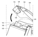
- FIG. 4 is a perspective view of the cleaner body when the cover member is open.
- FIG. 5 is a longitudinal cross-sectional view of FIG. 4.
- FIG. 6 is a perspective view of the cleaner body when the cover member is closed.
- FIG. 7 is a longitudinal cross-sectional view of FIG. 6.
- FIG 8 is a perspective view showing a state in which the suction device is coupled to the cleaner body.
- FIG. 9 is a longitudinal cross-sectional view of FIG. 8.
- FIG. 10 is a view showing a state in which the body portion of the cleaner body according to another embodiment of the present invention is inclined forward.
- FIG. 11 is a view showing a state in which the body portion is inclined rearward.
- FIG. 12 is a view showing a configuration of a support according to another embodiment of the present invention.
- 13 is a view sequentially showing a state in which the battery is coupled to the cleaner body.
- FIG. 14 is a view sequentially illustrating a state in which the battery is separated from the cleaner body.
- first, second, A, B, (a), and (b) may be used. These terms are only for distinguishing the components from other components, and the nature, order or order of the components are not limited by the terms. If a component is described as being “connected”, “coupled” or “connected” to another component, that component may be directly connected or connected to that other component, but between components It will be understood that may be “connected”, “coupled” or “connected”.
- FIG. 1 is a perspective view of a vacuum cleaner according to an embodiment of the present invention.
- a vacuum cleaner 1 according to an embodiment of the present invention includes a cleaner body 10 and a suction device 20.
- the cleaner body 10 includes a suction motor generating a suction force.
- the suction device 20 may guide air containing dust to the cleaner body 10.
- the suction device 20 may include a suction part 21 for sucking dust on a floor surface as an example of a cleaning surface, and a connection part 22, 23, 24 for connecting the suction part 21 to the cleaner body 10. ) May be included.
- the connection parts 22, 23, 24 may include an extension tube 24 connected to the suction part 21, a handle 22 connected to the extension tube 24, and the handle 22 to the main body 10. It may include a suction hose 23 to be connected to).
- the cleaner body 10 includes a main body 110 forming an overall appearance.
- the cleaner body 10 may further include a moving wheel 102 rotatably coupled to the body unit 110.
- the moving wheels 102 may be provided in pairs, and may be coupled to both sides of the main body unit 110, respectively.
- the main body 110 may be provided with a grip 104 for the user to grip.
- the user may grip the grip part 104 when lifting or tilting the main body part 110.
- the cleaner body 10 may further include a battery 106 for supplying power.
- the battery 106 may be detachably coupled to the main body 110.
- the battery 106 When the battery 106 is coupled to the main body 110, the battery 106 may be integrated with the main body 110. Accordingly, the battery 106 moves together with the main body 110.
- the battery 106 may supply power required for all driving of the vacuum cleaner 1.
- the battery 106 may be a rechargeable battery that can be charged and discharged.
- a power cord (not shown) for supplying commercial power may be separately connected to the battery 106.
- the cleaner body 10 further includes a dust container 120 in which dust sucked through the suction device 20 is stored.
- the dust container 120 may be formed in a cylindrical shape as shown, but is not limited to such a shape.
- the dust container 120 may be provided with a suction port 124 through which dust is sucked.
- the suction port 124 may be disposed on the upper surface of the dust container 120 as shown. Accordingly, the air introduced into the suction port 124 is guided downward to move to the storage space.
- the dust container 120 may be detachably mounted to the main body 110.
- a storage space may be formed in the dust container 120 to collect dust introduced into the suction port 124.
- the dust container 120 may be provided in front of the main body 110, the side portion of the dust container 120 may be made of at least a portion of a transparent material so that the user can check the dust collected in the storage space. .
- the vacuum cleaner 1 may include a dust separator (not shown) for separating the air and dust sucked from the suction device 20 from each other.
- the dust separator may be made of a separate article from the dust container 120 or may form a module with the dust container 120.
- the dust separator is provided inside the dust container 120, the dust separated from the dust separator may be collected below the dust container 120.
- FIG. 2 is a view showing a state in which the cleaner body and the suction device of FIG. 1 are separated
- FIG. 3 is a view showing the state in which the dust container of FIG. 2 is separated from the main body.
- the cleaner body 10 may include a connector 134 connected to the suction device 20.
- the connector 134 may be directly connected to the suction hose 23 to allow air containing dust to flow therein. That is, the connector 134 has one side coupled to the suction hose 23 and the other side coupled to the suction port 124. Accordingly, the connector 134 connects the suction hose 23 and the suction port 124.
- the connector 134 may communicate with the dust container 120. Accordingly, air introduced into the suction hose 23 may be introduced into the dust container 120 through the connector 134.
- One side of the dust container 120 may be provided with a suction port 124 to which dust is introduced.
- the suction port 124 may be provided on the upper portion (or upper surface portion) of the dust container 120 as shown.
- the suction port 124 may be formed to face the front.
- the front refers to a portion where the suction hose 23 is located with respect to the cleaner body 10.
- the connector 134 may be disposed above the dust container 120. Since both the suction port 124 and the connector 134 are disposed above the dust container 120, the length of the flow path of air introduced from the suction hose 23 can be minimized.
- the suction hose 23 may be provided with fitting parts 231, 232, and 233 to improve airtightness when combined with the connector 134.
- the fitting parts 231, 232, and 233 may attach and detach the suction hose 23 to the connector 134.
- the fitting parts 231, 232, and 233 may be formed to form multiple stages as shown.
- the fitting parts 231, 232, and 233 may include a first fitting part 231, a second fitting part 232, and a third fitting part 233.
- the first fitting part 231 and the second fitting part 232 are inserted into the connector 134. Accordingly, the first fitting part 231 and the second fitting part 232 may be collectively referred to as an inserting part, and may be referred to as a first inserting part and a second inserting part, respectively.
- the third fitting part 233 is provided outside the connector 134. The third fitting part 233 may contact the end of the connector 134 to limit the insertion depth of the insertion part.
- the cleaner body 10 further includes a cover member 130 that is movably provided in the main body 110.
- the cleaner body 10 may further include a connection member 13 connecting the cover member 130 and the main body 110.
- the cover member 130 may be rotatably connected to the main body 110 by the connection member 13.
- the cover member 130 may be provided with the connector 134. Accordingly, the connector 134 may move together with the cover member 130.
- the cover member 130 may shield at least one side of the dust container 120.
- the cover member 130 may be coupled to the dust container 120 while shielding at least one side of the dust container 120.
- the cover member 130 may be coupled to the upper portion of the dust container 120.
- the dust container 120 may be separated from the main body 110 as shown in FIG.
- the main body 110 may be provided with a seating portion 108 on which the dust container 120 is seated.
- the seating part 108 may be disposed below the dust container 120 as shown.
- a coupling part (not shown) may be formed at the seating part 108 to be coupled to the bottom part of the dust container 120.
- the bottom surface of the dust container 120 may be referred to as one side of the dust container 120, and the upper surface of the dust container 120 may be referred to as the other side of the dust container 120. Since the cover member 130 is coupled to the dust container 120 from the upper side of the dust container 120, the cover member 130 can be seen to be provided on the opposite side to the seating portion 108.
- FIG. 4 is a perspective view of the cleaner body when the cover member is open
- FIG. 5 is a longitudinal sectional view of FIG. 4
- FIG. 6 is a perspective view of the cleaner body when the cover member is closed
- FIG. 7 is a longitudinal sectional view of FIG. 6. to be.
- the cover member 130 When the cover member 130 is open, the user can draw out the dust container 120 to the outside. At this time, the suction port 124 of the dust container 120 is exposed to the outside.
- the cover member 130 When the cover member 130 is closed, at least one side of the dust container 120 is shielded by the cover member 130. When one side of the dust container 120 is shielded by the cover member 130, the suction port 124 is also shielded by the cover member 130.
- the cover member 130 does not shield the side surface of the dust container 120, the side surface of the dust container 120 is exposed to the outside. Accordingly, since at least a portion of the side surface of the dust container 120 is made of a transparent material, the user can visually check the amount of dust collected in the storage space inside the dust container 120.
- the inlet 124 When the inlet 124 is shielded by the cover member 130, the inlet 124 contacts the outlet of the connector 134. Accordingly, the connector 134 communicates with the suction port 124. In this case, the connector 134 may be aligned with the air inflow direction at the inlet 124.
- the first space part 135 is formed inside the connector 134, and the second space part 125 is formed inside the suction port 124. When the cover member 130 is closed, the first space 135 and the second space 125 is directly connected.
- the rear end of the connector 134 and the front end of the suction port 124 may be in close contact with each other, the airtight state, the air passing through the connector 134 to the outside Without leaking, all can be introduced into the dust container 120 through the suction port 124.
- the opened rear end of the connector 134 may extend to the inside of the cover member 130, and may extend to a position corresponding to the opened front end of the suction port 124 when the cover member 130 is closed. Can be.
- the first sealing part 136 may be formed at the rear end of the connector 134, and the second sealing part 126 may be formed at the front end of the suction port 124.
- the first sealing part 136 and the second sealing part 126 may be formed in a shape corresponding to each other in a position facing each other, and when the cover member 130 is closed to be in close contact with each other to be configured Can be.
- first sealing part 136 is formed to be inclined, and may be formed to have an inclination toward the front from the top to the bottom.
- the second sealing part 126 may be formed to be inclined in the same direction as the first sealing part 136, and may be formed to have an inclination toward the front from the upper side to the lower side.
- the inclined surfaces of the first sealing part 136 and the second sealing part 126 may be formed to correspond to the rotation direction in which the cover member 130 is opened and closed.
- Directions of the inclined surfaces of the first sealing part 136 and the second sealing part 126 may be formed to correspond to the tangent of the rotation radius of the cover member 130.
- the rotation center of the cover member 130 is located at the rear end of the cover member 130, the first sealing at a position away from the rotation center of the cover member 130 when the cover member 130 is rotated
- the inclination of the first sealing part 136 and the second sealing part 126 is a tangent of the rotation radius of the cover member 130. It may be formed to have a slope such as.
- the cover member 130 Due to the inclined structures of the first sealing part 136 and the second sealing part 126, the cover member 130 has the connector 134 and the suction port during the rotation operation in which the cover member 130 is closed. 124 may be effectively sealed without interference.
- the inside of the connector 134 and the inside of the suction port 124 may form a first space portion 135 and a second space portion 125, respectively, at the rear end and the second space of the first space portion 135.
- the front end of the space 125 may have a size corresponding to each other.
- the first sealing part 136 and the second sealing part 126 may be formed to have the same inclined surface, and thus, the first space part 135 and the first sealing part 130 are closed.
- the two spaces 125 may have a structure that is completely in communication with each other.
- the first sealing part 136 and the second sealing part 126 may be formed together when the connector 134 and the suction port 124 are formed. That is, the first sealing part 136 and the second sealing part 126 may be formed of a plastic material, respectively, and may be integrally formed with the connector 134 and the suction port 124.
- the first sealing part 136 and the second sealing part 126 may be equipped with a sealing member for airtightness.
- the sealing member may be formed around an open end of the first sealing part 136 and the second sealing part 126, and at least one of the first sealing part 136 and the second sealing part 126. It can be mounted on either.
- the sealing member may be formed of a material having elasticity such as rubber, silicone, or sponge. Therefore, when the cover member 130 is closed, the space between the first sealing portion 136 and the second sealing portion 126 may be completely sealed by compression of the sealing member.
- the cover member 130 may provide elasticity when the cover member 130 is closed or opened to mitigate an impact when the cover member 130 is closed and to facilitate initial rotation when the cover member 130 is opened. .
- first sealing part 136 and the second sealing part 126 may be formed of a separate material having elasticity as necessary. That is, the first sealing part 136 and the second sealing part 126 are separately formed of a material having elasticity such as rubber, silicone, sponge, etc., and then the rear end of the connector 134 and the front end of the suction port 124. It can be fixedly mounted on.
- first sealing part 136 and the second sealing part 126 may be mounted to be inclined, or the surfaces contacting each other may be formed to be inclined.
- the first sealing part 136 and the second sealing part 126 having elasticity may be formed to have a predetermined thickness so that the cover member 130 can be compressed with each other in a closed state.
- the first sealing part 136 and the second sealing part 126 may be completely sealed by the first sealing part 136 and the second sealing part 126 formed of an elastic material, and the cover member ( The opening and closing of the 130 may be alleviated the impact and facilitate the opening.
- first sealing part 136 and the second sealing part 126 are formed of an elastic material, when the cover member 130 is closed, the first sealing part 136 and the second sealing part ( 126 are pressed against each other. Therefore, in the state in which the cover member 130 is closed, the first sealing portion 136 and the second sealing portion 126 may be in close contact with each other, and the connector 134 and the suction port 124 may be in close contact with each other. The airtight performance can be further improved in between.
- FIG. 8 is a perspective view showing a state in which the suction device is coupled to the cleaner body
- Figure 9 is a longitudinal cross-sectional view of FIG.
- the suction hose 23 is connected to the connector 134.
- a front end (left side in FIG. 9) to which the suction hose 23 is connected may be defined as an inlet part, and a rear end (right side in FIG. 9) through which air is discharged may be defined as an outlet part.
- the outlet portion of the connector 134 may face the suction port 124 and contact each other.
- the outlet portion of the connector 134 may be in communication with the inlet 124, the first sealing portion 136 of the connector 134 and the second sealing portion 126 of the inlet 124 are mutually In close contact with each other, the connector 134 and the suction port 124 may be completely in communication with each other.
- the air discharged from the suction hose 23 may be introduced into the dust container 120 through the first space 135 and the second space 125.
- a flow path leading from the first space part 135 and the second space part 125 to the dust container 12 may be defined as a suction flow path F.
- the suction flow path F is introduced into the suction port 124 from the connector 134 and guided downward to move to the storage space.
- the suction flow path F may be divided into a first flow path defined in the first space part 135 and a second flow path defined in the second space part 125.
- the flow path is connected in a straight line due to the close contact between the first sealing part 136 and the second sealing part 126, and the suction hose 23 also has a straight line with the connector 134. Since the air is finally introduced through the suction hose 23 can be flowed in a straight state at the shortest distance toward the dust container (20).
- the airtightness between the suction hose 23 and the connector 134 may be maintained by the fitting parts 231, 232, and 233.
- the diameter of the first fitting part 231, the second fitting part 232, and the third fitting part 233 may be increased in order. Accordingly, a step may occur between the first fitting part 231 and the second fitting part 232, and a step may occur between the second fitting part 232 and the third fitting part 233. .
- the first fitting part 231 and the second fitting part 232 are inserted into the first space part 135.
- the connector 134 may be provided with stepped portions 134a and 134b. At least a part of the fitting parts 231, 232, and 233 may be caught by the stepped parts 134a and 134b to limit the insertion range. In addition, the stepped parts 134a and 134b are in surface contact with the fitting parts 231, 232, and 233, thereby improving airtightness between the fitting parts 231, 232, and 233 and the first space part 135. Can be.
- the stepped portions 134a and 134b may include a first stepped portion 134a and a second stepped portion 134b.
- the first stepped part 134a may be provided in the first space part 135. An end portion of the second fitting portion 232 may contact the first stepped portion 134a.
- the second stepped portion 134b may be provided outside the connector 134. An end portion of the third fitting portion 233 may contact the second stepped portion 134b.
- the suction hose 23 may be aligned in line with the air flow direction in the first space 135. Accordingly, the resistance acting on the air discharged from the suction hose 23 and flowing to the first space 135 is reduced.
- the vacuum cleaner 1 of the present invention has the suction hose 23, the connector 134, and the suction port 124 disposed in a line, and thus, a resistance acting on the air discharged from the suction hose 23. This is minimized.
- the stepped portion 134a of the suction hose 23 may extend to a position adjacent to the suction port 124 while being inserted into the connector 134. Therefore, the suction hose 23 may be in a state aligned with the suction port 124 in the connector 134. Therefore, the air discharged from the suction hose 23 can be flowed directly toward the suction port 124.
- first sealing portion 136 and the second sealing portion 126 formed on the connector 134 and the suction port 124 can be in close contact with each other in an inclined state to effectively maintain the airtight state and thus air It is possible to prevent leakage.
- air flow loss in the cleaner body 10 may be minimized, and as a result, suction efficiency of the vacuum cleaner 1 may be improved.
- the present invention may be various other embodiments in addition to the above-described embodiment.
- FIG. 10 is a view showing a state in which the body portion of the cleaner body according to another embodiment of the present invention is inclined forward.
- Figure 11 is a view showing a state in which the main body inclined rearward.
- Figure 12 is a view showing the configuration of the support according to another embodiment of the present invention.
- the cleaner body 1000 includes a main body 1110, a moving wheel 1120, and a battery 1130.
- the main body 1110 may include a dust container 1105 for storing dust sucked through the suction device 1160.
- the pair of moving wheels 1120 may be coupled to both sides of the main body 1110, respectively.
- the battery 1130 may be detachably coupled to the main body 1110.
- a portion in which the connector 1103 is disposed on the basis of the vertical line V passing through the rotation center of the moving wheel 1120 is defined as the front in the cleaner body 1000, and a portion in which the battery 1130 is disposed It can be defined as rear.
- the case in which the main body 1110 rotates forwardly means that the main body 1110 rotates in a counterclockwise direction (see FIG. 10) in the drawing, and the main body 1110 rotates backwards.
- the case of rotation means that the main body 1110 rotates clockwise (see FIG. 11).
- the cleaner body 1000 may further include a driving unit for driving the moving wheel 1120.
- the cleaner body 1000 may control the driving of the moving wheel 1120 by the controller according to the sensing information of the sensing unit that detects the movement of the cleaner body 1000.
- the moving wheel 1120 When the sensing unit is in an OFF state, the moving wheel 1120 may not be driven.
- the main body 1110 is inclined according to the position of the center of gravity. For example, when the center of gravity of the body portion 1110 is located in front of the vertical line (V) passing through the rotation center of the moving wheel 1120, the body portion 1110 is inclined forward as shown in FIG. When the center of gravity of the main body 1110 is located behind the vertical line V, the main body 1110 is inclined backward as shown in FIG. 11.
- the control unit drives the movement of the moving wheel 1120 such that the center of gravity of the main body 1110 is positioned on the vertical line V passing through the rotation center of the moving wheel 1120. Can be controlled.
- the bottom surface B of the main body 1110 may be spaced apart from the bottom surface G.
- the cleaner body 1000 may further include a rear wheel unit 1140.
- the rear wheel unit 1140 may be disposed at the rear of the bottom of the main body 1110, and may function to limit an angle at which the main body 1110 is inclined backward.
- the rear wheel unit 1140 may further include an extension 1144.
- An auxiliary wheel 1142 may be rotatably connected to one side of the extension 1144.
- the other side of the extension part 1144 may be rotatably connected to the main body part 1110 by the rotation shaft 1146.
- the extension 1144 may rotate upward or downward within the a-a ⁇ range.
- the rear wheel unit 1140 may further include an elastic member 1150.
- the elastic member 1150 may be a torsion spring.
- One end 1152 of the elastic member 1150 may be supported by the main body 1110, and the other end 1153 of the elastic member 1150 may be supported by the extension 1144.
- the elastic member 1150 may apply an elastic force so that the extension part 1144 rotates in the clockwise direction on the drawing.
- the front portion of the bottom surface B of the main body 1110 may contact the bottom surface G. Accordingly, the maximum rotation angle toward the front of the body portion 1110 may be limited.
- the rear wheel unit 1140 may contact the bottom surface G. Accordingly, the maximum rotation angle of the main body 1110 to the rear may be limited. Accordingly, the main body 1110 may be prevented from overturning forward or backward.
- the bottom surface B of the main body 1110 may form a predetermined angle ⁇ with the bottom surface G.
- an angle ⁇ between the bottom surface B and the bottom surface G of the main body 1110 may be approximately 17 ° to 20 °.
- the battery 1130 may be provided with a cover 1131.
- the cover 1131 may be exposed to the outside while the battery 1130 is mounted on the main body 1110. Accordingly, the cover 1131 may form at least a portion of an outer shape of the main body 1110.
- the user may detach the battery 1130 from the main body 1110 or couple to the main body 1110 without disassembling the main body 1110.
- the center of gravity of the main body 1110 is located in front of the main body 1110, and the battery 1130 is coupled to the main body 1110. In the case described below, only the case where the center of gravity of the main body 1110 is located at the rear.
- 13 is a view sequentially showing a state in which the battery is coupled to the cleaner body.
- FIG. 13A illustrates a state in which the battery 1130 is separated from the main body 1110.
- FIG. 13B is a view in which the battery 1130 is coupled to the main body 1110
- FIG. 13C is a view showing the main body 1110 inclined backward.
- the body part 1110 is provided with a battery coupling part 1107 to which the battery 1130 is coupled.
- the battery coupling part 1107 may be formed by recessing a part of the main body part 1110.
- the battery coupling unit 1107 is formed below the main body 1110, and thus the battery 1130 is coupled to the lower side of the main body 1110.
- the center of gravity of the battery 1130 may be located below the rotation center of the moving wheel 1120.
- the center of gravity of the main body 1110 may move downward, and thus driving stability of the cleaner main body 1000 may be improved.
- the center of gravity of the main body 1110 may be positioned in front of the vertical line passing through the center of the moving wheel 1120. Accordingly, when the battery 1130 is separated from the main body 1110, the main body 1110 may be tilted forward with respect to the moving wheel 1120.
- the front portion of the bottom surface of the body portion 1110 contacts the bottom surface, and the battery coupling portion 1107 obliquely faces upward. Accordingly, the user can easily combine the battery 1130.
- the battery 1130 may be coupled in an oblique direction to the main body 1110 by a coupling guide provided in the battery coupling unit 1107. Specifically, the insertion direction S of the battery 1130 may form an acute angle with the vertical line V and the bottom surface, respectively. Therefore, when the front portion of the bottom of the body portion 1110 contacts the bottom surface, the insertion direction S of the battery 1130 forms an acute angle with the bottom surface.
- the center of gravity of the main body 1110 may move rearward. That is, in the state in which the battery 1130 is coupled to the main body 1110, the center of gravity of the main body 1110 may be positioned behind the vertical line passing through the center of the moving wheel 1120.
- the main body 1110 may be inclined backward with respect to the moving wheel 1120.
- the rear wheel unit 1140 selectively contacts the bottom surface.
- the bottom surface B of the body portion 1110 forms a predetermined angle ⁇ with the bottom surface (G).
- FIG. 14 is a view sequentially illustrating a state in which the battery is separated from the cleaner body.
- FIG. 14 shows a state before the battery 1130 is separated from the main body 1110
- (b) of FIG. 14 shows that the battery 1130 is the main body 1110. Shows separation from
- a user may directly apply the force to the main body 1110 to tilt the main body 1110 forward.
- the user may separate the battery 1130 in a direction opposite to the insertion direction S.
- the main body 1110 may maintain a state inclined forward.
- the main body 1110 rotates backward so that the bottom of the main body 1110 is spaced apart from the bottom surface.
- the main body 1110 may be supported by two points by the moving wheel 1120 while driving.
- the cleaner body 1000 may more easily overcome obstacles, and the driving friction acting on the moving wheel 1120 is reduced, thereby reducing the labor required when the user moves the cleaner body 1000. You can.
- the center of gravity of the main body 1110 moves forward and the main body 1110 rotates forward, so that the rear of the main body 1110
- the battery coupling unit 1107 provided on the lower side is raised. Accordingly, a user can easily couple the battery 1130 to the battery coupler 1107.
- the suction efficiency of the vacuum cleaner may be improved, the industrial applicability is high.
Landscapes
- Engineering & Computer Science (AREA)
- Mechanical Engineering (AREA)
- Nozzles For Electric Vacuum Cleaners (AREA)
- Electric Vacuum Cleaner (AREA)
Abstract
Description
Claims (20)
- 흡입력을 발생시키기 위한 흡입모터를 구비하는 청소기 본체; 및A cleaner body having a suction motor for generating a suction force; And상기 청소기 본체와 연통되어 먼지가 포함된 공기를 흡입하는 흡입호스를 포함하고,A suction hose communicating with the cleaner body to suck air containing dust,상기 청소기 본체는, The cleaner body,본체부;Main body;상기 본체부에 구비되며, 상기 흡입호스를 통해 흡입된 공기가 유입되는 흡입구 및 먼지가 포집되는 저장공간이 구비되는 먼지통; 및 A dust container provided in the main body, and having a suction port through which air sucked through the suction hose flows and a storage space for collecting dust; And일측이 상기 흡입호스와 연결되는 커넥터가 구비되며, 상기 먼지통의 적어도 일부를 선택적으로 차폐하는 커버부재를 포함하고,One side is provided with a connector connected to the suction hose, and includes a cover member for selectively shielding at least a portion of the dust container,상기 커버부재가 상기 먼지통의 일측을 차폐하면, 상기 커넥터는 상기 흡입구에서의 공기 유입 방향과 나란하게 정렬되는 진공 청소기.When the cover member shields one side of the dust container, the connector is aligned with the air inflow direction at the suction port.
- 제 1 항에 있어서,The method of claim 1,상기 커넥터는 상기 흡입호스로부터 공기가 유입되는 입구부와 공기가 배출되는 출구부를 포함하고,The connector includes an inlet portion through which air is introduced from the suction hose and an outlet portion through which air is discharged.상기 커버부재가 상기 먼지통을 차폐하면, 상기 커넥터의 출구부는 상기 흡입구와 접촉되는 진공 청소기.And the outlet of the connector contacts the suction port when the cover member shields the dust container.
- 제 2 항에 있어서,The method of claim 2,상기 커넥터의 출구부와 상기 흡입구 사이에는 기밀성을 유지하기 위한 실링부재가 구비되는 진공 청소기.And a sealing member provided between the outlet of the connector and the suction port to maintain airtightness.
- 제 1 항에 있어서,The method of claim 1,상기 커넥터는 상기 흡입호스를 통해 유입되는 공기의 유입 방향과 나란하게 정렬되는 진공 청소기.The connector is arranged in parallel with the inflow direction of the air flowing through the suction hose.
- 제 1 항에 있어서,The method of claim 1,상기 흡입호스에는 상기 커넥터와 기밀성을 유지하기 위한 피팅부가 구비되고, 상기 피팅부의 적어도 일부분은 상기 커넥터에 삽입되는 진공 청소기. The suction hose is provided with a fitting for maintaining the air tightness with the connector, at least a portion of the vacuum cleaner is inserted into the connector.
- 제 5 항에 있어서,The method of claim 5,상기 커넥터 내부에는 상기 피팅부의 일부분과 접촉하여 상기 피팅부의 삽입 범위를 제한하는 단턱부가 구비되는 진공 청소기.The connector has a stepped portion inside the connector to contact the portion of the fitting portion to limit the insertion range of the fitting portion.
- 제 1 항에 있어서,The method of claim 1,상기 커버부재가 상기 먼지통의 일측을 차폐하면, 상기 먼지통의 측면부는 외부로 노출되고,When the cover member shields one side of the dust container, the side portion of the dust container is exposed to the outside,사용자가 상기 저장공간에 포집된 먼지를 확인할 수 있도록, 상기 먼지통의 측면부는 적어도 일부분이 투명 재질로 이루어진 진공 청소기.At least a portion of the side surface of the dust container is a vacuum cleaner made of a transparent material so that the user can check the dust collected in the storage space.
- 제 1 항에 있어서,The method of claim 1,상기 커버부재를 상기 본체부에 회전 가능하게 연결하는 연결부재를 더 포함하는 진공 청소기.And a connecting member rotatably connecting the cover member to the main body.
- 제 1 항에 있어서,The method of claim 1,상기 커버부재에는 사용자가 파지하기 위한 그립부가 구비되는 진공 청소기.The cover member is provided with a grip portion for holding the vacuum cleaner by the user.
- 제 1 항에 있어서,The method of claim 1,상기 본체부에는 상기 먼지통이 안착되는 안착부가 구비되는 진공 청소기.The main body unit is a vacuum cleaner provided with a seating portion for mounting the dust container.
- 흡입력을 발생시키기 위한 흡입모터를 구비하는 청소기 본체; 및A cleaner body having a suction motor for generating a suction force; And상기 청소기 본체와 연통되어 먼지가 포함된 공기를 흡입하는 흡입호스를 포함하고,A suction hose communicating with the cleaner body to suck air containing dust,상기 청소기 본체는, The cleaner body,상기 흡입호스와 연결되는 흡입구 및 상기 흡입구를 통해 유입된 먼지가 저장되는 저장공간이 구비되는 먼지통; 및 A dust container having a suction port connected to the suction hose and a storage space for storing dust introduced through the suction port; And상기 먼지통과 결합되는 커버부재를 포함하고,A cover member coupled to the dust container,상기 커버부재에는 상기 흡입호스와 상기 먼지통을 연결하는 커넥터가 구비되며,The cover member is provided with a connector connecting the suction hose and the dust container,상기 커넥터로부터 상기 흡입구로 유입된 공기는 하방으로 가이드되어 상기 저장공간으로 이동하는 진공 청소기.The air introduced from the connector to the suction port is guided downward to move to the storage space.
- 흡입력을 발생시키기 위한 흡입모터를 구비하는 청소기 본체; 및A cleaner body having a suction motor for generating a suction force; And상기 청소기 본체와 연통되어 먼지가 포함된 공기를 흡입하는 흡입호스를 포함하고,A suction hose communicating with the cleaner body to suck air containing dust,상기 청소기 본체는, The cleaner body,공기가 유입되는 흡입구가 구비되는 먼지통; 및 A dust container provided with a suction port through which air is introduced; And상기 먼지통과 결합되는 커버부재를 포함하고,A cover member coupled to the dust container,상기 커버부재에는 일측이 상기 흡입호스와 연결되고, 타측이 상기 흡입구와 연결되는 커넥터가 구비되며,The cover member is provided with a connector on one side is connected to the suction hose, the other side is connected to the suction port,상기 흡입구는 상기 먼지통의 상면부에 구비되는 진공 청소기.The suction port is a vacuum cleaner provided in the upper surface portion of the dust container.
- 흡입력을 발생시키는 흡입 모터가 구비되는 청소기 본체;A cleaner body having a suction motor generating a suction force;상기 청소기 본체와 연통되어 먼지가 포함된 공기를 흡입하는 흡입호스;A suction hose communicating with the cleaner body to suck air containing dust;상기 청소기 본체 전면에 안착되되, 전면 일부가 외부로 노출되는 먼지통;A dust container seated on the front surface of the cleaner body, the front part of which is exposed to the outside;상기 청소기 본체에 회동 가능하게 장착되며, 상기 먼지통을 상방에서 차폐하는 커버부재;A cover member rotatably mounted to the cleaner body and shielding the dust container from above;상기 커버부재에 의해 차폐되도록 상기 먼지통에 개구되며, 상기 흡입 호스를 통해서 흡입되는 먼지를 포함한 공기가 상기 먼지통 내부로 유입되는 통로를 형성하는 흡입구; 및An inlet opening formed in the dust container so as to be shielded by the cover member and defining a passage through which air including dust sucked through the suction hose flows into the dust container; And상기 흡입구와 동일 연장선상에서 상기 커버부재에 개구되도록 형성되어 상기 흡입호스가 연결되며, 상기 흡입구까지 연장되는 통로를 형성하는 커넥터;를 포함하는 진공 청소기.And a connector which is formed to be opened in the cover member on the same extension line as the suction port, the suction hose is connected, and forms a passage extending to the suction port.
- 제 13 항에 있어서,The method of claim 13,상기 커넥터의 개구된 일단에는 제 1 실링부가 형성되고, A first sealing portion is formed at the open end of the connector,상기 제 1 실링부와 마주보는 상기 흡입구의 개구된 일단에는 상기 제 1 실링부와 대응하는 형상으로 형성되는 제 2 실링부가 형성되며,A second sealing part formed in a shape corresponding to the first sealing part is formed at an open end of the suction port facing the first sealing part.상기 제 1 실링부와 제 2 실링부는 상기 커버부재가 닫히게 될 때 서로 결합되어 상기 커넥터와 흡입구 사이를 기밀 시키는 진공 청소기.And the first sealing part and the second sealing part are coupled to each other when the cover member is closed to seal the gap between the connector and the suction port.
- 제 13 항에 있어서,The method of claim 13,상기 커넥터의 개구된 단부에는 경사지게 형성되는 제 1 실링부가 형성되고,At the open end of the connector is formed a first sealing portion which is formed to be inclined,상기 제 1 실링부와 마주보는 상기 흡입구의 개구된 단부에는 상기 제 1 실링부와 동일 각도록 경사지게 형성되는 제 2 실링부가 형성되며,At the open end of the suction port facing the first sealing part, a second sealing part which is formed to be inclined at the same angle as the first sealing part is formed.상기 커버부재가 닫히게 되면 상기 제 1 실링부와 제 2 실링부는 서로 밀착 되는 진공 청소기.And the first sealing part and the second sealing part are in close contact with each other when the cover member is closed.
- 제 15 항에 있어서,The method of claim 15,상기 제 1 실링부와 제 2 실링부는 상기 흡입호스가 연결되는 전방으로 갈수록 하단이 더 돌출되는 기울기를 가지도록 형성되는 진공 청소기.And the first sealing part and the second sealing part are formed to have a slope at which a lower end thereof protrudes further toward the front to which the suction hose is connected.
- 제 15 항에 있어서,The method of claim 15,상기 제 1 실링부와 제 2 실링부는 탄성소재로 형성되며, 상기 커넥터와 흡입구에 각각 장착되는 진공 청소기.The first sealing portion and the second sealing portion is formed of an elastic material, the vacuum cleaner is mounted to the connector and the suction port, respectively.
- 제 13 항에 있어서,The method of claim 13,상기 커넥터와 상기 커넥터에 연결되는 흡입 호스의 단부와 상기 흡입구는 동일 연장선상에 정렬되는 진공 청소기.And the end of the connector and the suction hose connected to the connector and the suction port are aligned on the same extension line.
- 제 13 항에 있어서,The method of claim 13,상기 커버 부재는 닫힌 상태에서 상기 먼지통의 상부를 수용하여 상기 먼지통을 구속하는 진공 청소기.The cover member is a vacuum cleaner for accommodating the upper portion of the dust container in the closed state to confine the dust container.
- 제 13 항에 있어서,The method of claim 13,상기 청소기 본체에는 상기 먼지통 하면을 하방에서 지지하도록 전방으로 연장되는 안착부가 형성되며,The cleaner body is provided with a seating portion extending forward to support the lower surface of the dust container from below,상기 먼지통은 상기 안착부와 커버부재에 의해 하단과 상단이 구속되며, 상기 안착부와 커버부재의 사이를 통해 외부로 노출되는 진공 청소기.The dust container is the bottom and the top is restrained by the seating portion and the cover member, the vacuum cleaner is exposed to the outside through the seating portion and the cover member.
Priority Applications (5)
| Application Number | Priority Date | Filing Date | Title |
|---|---|---|---|
| EP17760266.1A EP3424388B1 (en) | 2016-02-29 | 2017-02-27 | Vacuum cleaner |
| JP2018542287A JP2019504715A (en) | 2016-02-29 | 2017-02-27 | Vacuum cleaner |
| AU2017227407A AU2017227407B2 (en) | 2016-02-29 | 2017-02-27 | Vacuum cleaner |
| RU2018134032A RU2696639C1 (en) | 2016-02-29 | 2017-02-27 | Vacuum cleaner |
| CN201780011005.6A CN108601493B (en) | 2016-02-29 | 2017-02-27 | Vacuum cleaner with a vacuum cleaner head |
Applications Claiming Priority (6)
| Application Number | Priority Date | Filing Date | Title |
|---|---|---|---|
| KR10-2016-0024022 | 2016-02-29 | ||
| KR20160024022 | 2016-02-29 | ||
| KR10-2016-0036277 | 2016-03-25 | ||
| KR20160036277 | 2016-03-25 | ||
| KR1020160184161A KR101903257B1 (en) | 2016-03-25 | 2016-12-30 | Vacuum cleaner |
| KR10-2016-0184161 | 2016-12-30 |
Publications (1)
| Publication Number | Publication Date |
|---|---|
| WO2017150862A1 true WO2017150862A1 (en) | 2017-09-08 |
Family
ID=59069284
Family Applications (1)
| Application Number | Title | Priority Date | Filing Date |
|---|---|---|---|
| PCT/KR2017/002145 WO2017150862A1 (en) | 2016-02-29 | 2017-02-27 | Vacuum cleaner |
Country Status (3)
| Country | Link |
|---|---|
| US (1) | US10426303B2 (en) |
| DE (1) | DE202017001077U1 (en) |
| WO (1) | WO2017150862A1 (en) |
Families Citing this family (15)
| Publication number | Priority date | Publication date | Assignee | Title |
|---|---|---|---|---|
| TWI664943B (en) * | 2016-02-29 | 2019-07-11 | Lg電子股份有限公司 | Vacuum cleaner |
| AU2017227412B2 (en) * | 2016-02-29 | 2020-01-23 | Lg Electronics Inc. | Vacuum cleaner |
| TWI664944B (en) | 2016-02-29 | 2019-07-11 | Lg電子股份有限公司 | Vacuum cleaner |
| TWI643597B (en) * | 2016-02-29 | 2018-12-11 | Lg電子股份有限公司 | Vacuum cleaner |
| GB2564035B8 (en) | 2016-02-29 | 2021-07-07 | Lg Electronics Inc | Vacuum cleaner |
| DE202017000984U1 (en) | 2016-02-29 | 2017-05-29 | Lg Electronics Inc. | vacuum cleaner |
| TWI636758B (en) * | 2016-02-29 | 2018-10-01 | Lg電子股份有限公司 | Vacuum cleaner |
| TWI653962B (en) * | 2016-02-29 | 2019-03-21 | Lg電子股份有限公司 | Vacuum cleaner |
| TWI643596B (en) | 2016-02-29 | 2018-12-11 | Lg電子股份有限公司 | Vacuum cleaner |
| WO2017150862A1 (en) | 2016-02-29 | 2017-09-08 | 엘지전자 주식회사 | Vacuum cleaner |
| TWI637718B (en) | 2016-02-29 | 2018-10-11 | Lg電子股份有限公司 | Vacuum cleaner |
| TWI641353B (en) * | 2016-02-29 | 2018-11-21 | Lg電子股份有限公司 | Vacuum cleaner |
| DE202017000985U1 (en) | 2016-02-29 | 2017-05-29 | Lg Electronics Inc. | vacuum cleaner |
| JP6714091B2 (en) | 2016-02-29 | 2020-06-24 | エルジー エレクトロニクス インコーポレイティド | Vacuum cleaner |
| DE202017002619U1 (en) | 2016-05-20 | 2017-08-04 | Lg Electronics Inc. | vacuum cleaner |
Citations (6)
| Publication number | Priority date | Publication date | Assignee | Title |
|---|---|---|---|---|
| JP2002028121A (en) * | 2000-07-18 | 2002-01-29 | Toshiba Tec Corp | Vacuum cleaner |
| JP2003038404A (en) * | 2001-07-31 | 2003-02-12 | Sanyo Electric Co Ltd | Electric vacuum cleaner |
| KR100449933B1 (en) * | 1995-10-30 | 2004-12-16 | 코닌클리케 필립스 일렉트로닉스 엔.브이. | Vacuum cleaner hose assembly with swivel bands and vacuum cleaner with this assembly |
| KR20100019146A (en) * | 2008-08-08 | 2010-02-18 | 엘지전자 주식회사 | Vacuum cleaner |
| KR20120004100A (en) | 2010-07-06 | 2012-01-12 | 엘지전자 주식회사 | A vacuum cleaner |
| KR101552437B1 (en) * | 2014-05-12 | 2015-09-10 | 엘지전자 주식회사 | Vacuum cleaner |
Family Cites Families (107)
| Publication number | Priority date | Publication date | Assignee | Title |
|---|---|---|---|---|
| US2811737A (en) | 1954-05-06 | 1957-11-05 | Gen Electric | Mobile electric vacuum cleaner |
| KR890004031Y1 (en) | 1987-02-03 | 1989-06-17 | 삼성전자주식회사 | Suction cleaners |
| DE3863282D1 (en) | 1987-11-11 | 1991-07-18 | Siemens Ag | MOBILE VACUUM CLEANER. |
| US4831683A (en) | 1988-09-02 | 1989-05-23 | Riccar America Company | Vacuum cleaner |
| US4962453A (en) | 1989-02-07 | 1990-10-09 | Transitions Research Corporation | Autonomous vehicle for working on a surface and method of controlling same |
| KR920010563B1 (en) | 1988-11-09 | 1992-12-07 | 주식회사 금성사 | Electric vacuum cleaner |
| JPH0718716B2 (en) | 1991-07-19 | 1995-03-06 | 近畿コンクリート工業株式会社 | Foundation block for collective meter box and its buried structure |
| JPH07236599A (en) | 1994-03-01 | 1995-09-12 | Matsushita Electric Ind Co Ltd | Vacuum cleaner |
| KR970032722A (en) | 1995-12-19 | 1997-07-22 | 최진호 | Cordless cleaner |
| US5926909A (en) | 1996-08-28 | 1999-07-27 | Mcgee; Daniel | Remote control vacuum cleaner and charging system |
| JPH114787A (en) | 1997-06-18 | 1999-01-12 | Matsushita Electric Ind Co Ltd | Vacuum cleaner |
| US6226830B1 (en) | 1997-08-20 | 2001-05-08 | Philips Electronics North America Corp. | Vacuum cleaner with obstacle avoidance |
| US5991972A (en) | 1998-02-09 | 1999-11-30 | Rexair, Inc. | Height adjustment mechanism for a cleaning tool |
| TW529406U (en) | 1999-01-29 | 2003-04-21 | Hitachi Ltd | Vacuum cleaner |
| TW471954B (en) | 2000-03-01 | 2002-01-11 | Matsushita Electric Ind Co Ltd | Electric cleaner |
| JP2001321310A (en) | 2000-05-16 | 2001-11-20 | Hitachi Ltd | Vacuum cleaner |
| KR100662282B1 (en) | 2000-11-14 | 2007-01-02 | 엘지전자 주식회사 | covers structure of a vacuum cleaner |
| TWI240622B (en) | 2001-06-14 | 2005-10-01 | Sanyo Electric Co | Dust collection device |
| JP3656835B2 (en) * | 2001-07-09 | 2005-06-08 | 東芝テック株式会社 | Electric vacuum cleaner |
| JP2003093302A (en) | 2001-09-26 | 2003-04-02 | Toshiba Corp | Battery-drive vacuum cleaner |
| JP2003169771A (en) | 2001-12-07 | 2003-06-17 | Toshiba Tec Corp | Storage battery cooling device for vacuum cleaner |
| CN2607938Y (en) | 2001-12-27 | 2004-03-31 | 松下电器产业株式会社 | Motor-driven vacuum cleaner and nozzle of suction cleaner |
| JP2004033628A (en) | 2002-07-05 | 2004-02-05 | Toshiba Tec Corp | Vacuum cleaner |
| KR200294697Y1 (en) | 2002-07-11 | 2002-11-13 | 삼성광주전자 주식회사 | Indicator lamp device for cleaner |
| CN1292696C (en) | 2002-07-25 | 2007-01-03 | 东芝泰格有限公司 | Vacuum cleaner |
| WO2004032696A2 (en) | 2002-10-10 | 2004-04-22 | Polar Light Limited | Method and apparatus to control the power delivery to an appliance |
| KR20050064945A (en) | 2003-12-24 | 2005-06-29 | 주식회사 대우일렉트로닉스 | Dual releasing cover of the vacuum cleaner |
| JP2005211462A (en) | 2004-01-30 | 2005-08-11 | Funai Electric Co Ltd | Self-propelled cleaner |
| EP1748716A4 (en) | 2004-05-03 | 2009-08-26 | Charles A Castronovo | Vacuum cleaners especially quiet vacuum cleaners, pumps, and engines |
| CN1698527A (en) | 2004-05-19 | 2005-11-23 | 乐金电子(天津)电器有限公司 | Rotation speed reducing structure of dust collection chamber cap of vacuum cleaner |
| KR100634470B1 (en) | 2004-12-03 | 2006-10-16 | 주식회사 대우일렉트로닉스 | Vacuum cleaner having air cleaning function |
| KR100677982B1 (en) | 2004-12-27 | 2007-02-02 | 엘지전자 주식회사 | Motor filter mounting structure of a vacuum cleaner |
| KR100697429B1 (en) | 2004-12-27 | 2007-03-20 | 엘지전자 주식회사 | Vacuum cleaner |
| KR20060082900A (en) | 2005-01-13 | 2006-07-20 | 주식회사 대우일렉트로닉스 | Handle for vacuum cleaner |
| DE102005007925B4 (en) | 2005-02-11 | 2006-11-02 | Alfred Kärcher Gmbh & Co. Kg | suction device |
| AU2006214016B2 (en) | 2005-02-18 | 2011-11-10 | Irobot Corporation | Autonomous surface cleaning robot for wet and dry cleaning |
| JP4253311B2 (en) | 2005-03-25 | 2009-04-08 | 株式会社東芝 | Electric vacuum cleaner |
| KR100640830B1 (en) | 2005-05-11 | 2006-11-02 | 엘지전자 주식회사 | Dust collector for vacuum cleaner |
| JP4553793B2 (en) | 2005-05-13 | 2010-09-29 | 三菱電機株式会社 | Vacuum cleaner |
| KR101196128B1 (en) | 2005-05-16 | 2012-10-30 | 엘지전자 주식회사 | Open/closing apparatus of dust collecting unit |
| KR100788791B1 (en) | 2006-05-01 | 2008-01-02 | 주식회사 한울로보틱스 | The control method of cleaning action for cleaning robot |
| MX2008016122A (en) | 2006-09-22 | 2009-04-15 | Shop Vac Corp | Leaf shredder vacuum. |
| KR100807409B1 (en) | 2006-12-22 | 2008-02-25 | 주식회사 유진로봇 | A robot cleaner for the weightcenter of construction eccentrically |
| KR100831784B1 (en) | 2007-03-02 | 2008-05-28 | 엘지전자 주식회사 | Vacuum cleaner |
| KR100840889B1 (en) | 2007-03-21 | 2008-06-24 | 한경희 | Dust collecting container |
| KR100829094B1 (en) | 2007-03-23 | 2008-05-16 | 주식회사 인터텍 | Robot cleaner with sensor modulation |
| KR100876695B1 (en) | 2007-05-09 | 2008-12-31 | 엘지전자 주식회사 | Vacuum cleaners that control standing and maneuver |
| EP2129274B1 (en) | 2007-03-28 | 2013-02-20 | LG Electronics Inc. | Vacuum cleaner |
| KR100876698B1 (en) | 2007-05-09 | 2008-12-31 | 엘지전자 주식회사 | Active driven cleaner |
| EP1974642B1 (en) | 2007-03-30 | 2012-06-27 | Kabushiki Kaisha Toshiba | Electric vacuum cleaner |
| JP5012224B2 (en) | 2007-06-05 | 2012-08-29 | パナソニック株式会社 | Electric vacuum cleaner |
| KR101340423B1 (en) | 2007-08-28 | 2013-12-13 | 삼성전자주식회사 | A Stick Type Vacuum Cleaner |
| DE102007043725A1 (en) | 2007-09-13 | 2009-04-02 | BSH Bosch und Siemens Hausgeräte GmbH | Mobile vacuum cleaner and swivel castor of a mobile vacuum cleaner |
| KR101471026B1 (en) | 2008-03-05 | 2014-12-11 | 삼성전자주식회사 | Vacuum cleaner in which dust bag or cyclone dust collecting apparatus is selectively mounted |
| CN101554306B (en) | 2008-04-11 | 2012-06-27 | 乐金电子(天津)电器有限公司 | Active-drive type vacuum cleaner |
| JP5430886B2 (en) | 2008-06-30 | 2014-03-05 | 株式会社東芝 | Electric vacuum cleaner |
| KR101026065B1 (en) | 2008-08-18 | 2011-04-04 | 엘지전자 주식회사 | A switching device of cover for cleanner and switching structure using of the same |
| KR101166285B1 (en) | 2008-08-07 | 2012-07-17 | 엘지전자 주식회사 | Vacuunm cleaner |
| KR100869537B1 (en) | 2008-08-25 | 2008-11-19 | 주식회사 동영티엔디 | Water suction device used with vacuum cleaner |
| KR101524797B1 (en) | 2008-10-17 | 2015-06-02 | 삼성전자주식회사 | Wheel Assembly |
| KR20100047638A (en) | 2008-10-29 | 2010-05-10 | 주식회사 대우일렉트로닉스 | Auto cleaner |
| US8062398B2 (en) * | 2008-12-19 | 2011-11-22 | Bissell Homecare, Inc. | Vacuum cleaner and cyclone module therefor |
| US9089248B2 (en) | 2009-02-16 | 2015-07-28 | Samsung Electronics Co., Ltd. | Fan motor apparatus having diffuser unit for vacuum cleaner |
| KR101123185B1 (en) | 2009-03-18 | 2012-03-19 | 에이스전자(주) | Robot cleaner |
| KR20100116834A (en) | 2009-04-23 | 2010-11-02 | 삼성광주전자 주식회사 | Upright type vacuum cleaner |
| CN105769054A (en) | 2009-05-08 | 2016-07-20 | 伊莱克斯公司 | Detachable Dust Receptacle For A Vacuum Cleaner |
| DE102009035603B4 (en) | 2009-07-31 | 2018-01-25 | BSH Hausgeräte GmbH | Vacuum cleaner with removable lid |
| JP5417220B2 (en) | 2010-02-26 | 2014-02-12 | 株式会社東芝 | Electric vacuum cleaner |
| KR101666902B1 (en) | 2010-08-20 | 2016-10-17 | 엘지전자 주식회사 | Controlling Method of Cleaner |
| JP5647041B2 (en) | 2011-03-15 | 2014-12-24 | 日立アプライアンス株式会社 | Electric vacuum cleaner |
| KR101844221B1 (en) | 2011-04-19 | 2018-04-02 | 엘지전자 주식회사 | A vacuum cleaner comprising a wheel assembly |
| KR20130029852A (en) | 2011-09-16 | 2013-03-26 | 주식회사 와이즈오토모티브 | Cleaning robot for enabling set up data of cleaning area and verification of after cleaning real cleaning area and system for controlling the same |
| JP5931385B2 (en) | 2011-09-22 | 2016-06-08 | 株式会社東芝 | Electric vacuum cleaner |
| KR101929813B1 (en) | 2012-02-21 | 2019-03-14 | 엘지전자 주식회사 | Autonomous mobile cleaner and moving method of the same |
| JP6068824B2 (en) | 2012-05-01 | 2017-01-25 | シャープ株式会社 | Self-propelled electronic device |
| GB2503252B (en) | 2012-06-20 | 2014-12-17 | Dyson Technology Ltd | A self righting cleaning appliance |
| KR102082746B1 (en) | 2013-06-11 | 2020-02-28 | 삼성전자주식회사 | Vacuum cleaner |
| KR101495732B1 (en) | 2013-07-16 | 2015-02-25 | 엘지전자 주식회사 | Vacuum cleaner |
| KR102274369B1 (en) | 2013-09-23 | 2021-07-07 | 삼성전자주식회사 | Vacuum cleaner |
| JP6429449B2 (en) | 2013-10-28 | 2018-11-28 | シャープ株式会社 | Electric vacuum cleaner |
| KR102153896B1 (en) | 2013-10-28 | 2020-09-09 | 삼성전자주식회사 | Vacuum cleaner |
| JP6302648B2 (en) | 2013-11-15 | 2018-03-28 | シャープ株式会社 | Electric vacuum cleaner |
| US9980618B2 (en) | 2014-02-13 | 2018-05-29 | Makita Corporation | Dust collecting device |
| JP6158119B2 (en) | 2014-03-12 | 2017-07-05 | 日立アプライアンス株式会社 | Electric vacuum cleaner |
| JP2016015974A (en) | 2014-07-04 | 2016-02-01 | 株式会社東芝 | Vacuum cleaner |
| KR20160028182A (en) | 2014-09-03 | 2016-03-11 | 삼성전자주식회사 | A dust collector, a cleaning apparatus using the dust collector and a method for controlling the same |
| KR102312095B1 (en) | 2014-12-26 | 2021-10-13 | 엘지전자 주식회사 | Autonomous mobile cleaner and method of contorlling the same |
| KR20170000071A (en) | 2015-06-23 | 2017-01-02 | 엘지전자 주식회사 | Vacuum cleaner and method for controlling the same |
| TWI618523B (en) | 2015-07-29 | 2018-03-21 | Lg電子股份有限公司 | Vacuum cleaner |
| KR101684171B1 (en) | 2015-09-14 | 2016-12-07 | 엘지전자 주식회사 | Vacuum cleaner |
| EP3403560B1 (en) | 2016-02-29 | 2020-08-12 | LG Electronics Inc. | Vacuum cleaner and method of displaying state thereof |
| JP6714091B2 (en) | 2016-02-29 | 2020-06-24 | エルジー エレクトロニクス インコーポレイティド | Vacuum cleaner |
| TWI664943B (en) | 2016-02-29 | 2019-07-11 | Lg電子股份有限公司 | Vacuum cleaner |
| AU2017227412B2 (en) | 2016-02-29 | 2020-01-23 | Lg Electronics Inc. | Vacuum cleaner |
| CN108697289B (en) | 2016-02-29 | 2020-09-01 | Lg电子株式会社 | Vacuum cleaner with a vacuum cleaner head |
| TWI637718B (en) | 2016-02-29 | 2018-10-11 | Lg電子股份有限公司 | Vacuum cleaner |
| TWI643597B (en) | 2016-02-29 | 2018-12-11 | Lg電子股份有限公司 | Vacuum cleaner |
| TWI636758B (en) | 2016-02-29 | 2018-10-01 | Lg電子股份有限公司 | Vacuum cleaner |
| TWI641353B (en) | 2016-02-29 | 2018-11-21 | Lg電子股份有限公司 | Vacuum cleaner |
| GB2564035B8 (en) | 2016-02-29 | 2021-07-07 | Lg Electronics Inc | Vacuum cleaner |
| WO2017150862A1 (en) | 2016-02-29 | 2017-09-08 | 엘지전자 주식회사 | Vacuum cleaner |
| TWI653962B (en) | 2016-02-29 | 2019-03-21 | Lg電子股份有限公司 | Vacuum cleaner |
| TWI664944B (en) | 2016-02-29 | 2019-07-11 | Lg電子股份有限公司 | Vacuum cleaner |
| DE202017000985U1 (en) | 2016-02-29 | 2017-05-29 | Lg Electronics Inc. | vacuum cleaner |
| TWI643596B (en) | 2016-02-29 | 2018-12-11 | Lg電子股份有限公司 | Vacuum cleaner |
| DE202017000984U1 (en) | 2016-02-29 | 2017-05-29 | Lg Electronics Inc. | vacuum cleaner |
| JP7236599B1 (en) | 2021-09-09 | 2023-03-09 | 日本ペイント・サーフケミカルズ株式会社 | Aqueous surface treatment agent and surface treated metal |
-
2017
- 2017-02-27 WO PCT/KR2017/002145 patent/WO2017150862A1/en active Application Filing
- 2017-02-28 DE DE202017001077.1U patent/DE202017001077U1/en active Active
- 2017-02-28 US US15/444,761 patent/US10426303B2/en active Active
Patent Citations (6)
| Publication number | Priority date | Publication date | Assignee | Title |
|---|---|---|---|---|
| KR100449933B1 (en) * | 1995-10-30 | 2004-12-16 | 코닌클리케 필립스 일렉트로닉스 엔.브이. | Vacuum cleaner hose assembly with swivel bands and vacuum cleaner with this assembly |
| JP2002028121A (en) * | 2000-07-18 | 2002-01-29 | Toshiba Tec Corp | Vacuum cleaner |
| JP2003038404A (en) * | 2001-07-31 | 2003-02-12 | Sanyo Electric Co Ltd | Electric vacuum cleaner |
| KR20100019146A (en) * | 2008-08-08 | 2010-02-18 | 엘지전자 주식회사 | Vacuum cleaner |
| KR20120004100A (en) | 2010-07-06 | 2012-01-12 | 엘지전자 주식회사 | A vacuum cleaner |
| KR101552437B1 (en) * | 2014-05-12 | 2015-09-10 | 엘지전자 주식회사 | Vacuum cleaner |
Also Published As
| Publication number | Publication date |
|---|---|
| US10426303B2 (en) | 2019-10-01 |
| US20170245703A1 (en) | 2017-08-31 |
| DE202017001077U1 (en) | 2017-05-29 |
Similar Documents
| Publication | Publication Date | Title |
|---|---|---|
| WO2017150862A1 (en) | Vacuum cleaner | |
| WO2017150829A1 (en) | Vacuum cleaner | |
| WO2021002625A1 (en) | Robot cleaner station | |
| WO2021025377A1 (en) | Station of robot cleaner | |
| WO2022005013A1 (en) | Cleaning device comprising vacuum cleaner and docking station | |
| WO2020262863A1 (en) | Robot cleaner, station, and cleaning system | |
| WO2017150816A1 (en) | Vacuum cleaner | |
| WO2020122473A1 (en) | Robot cleaner, station and cleaning system | |
| WO2020153672A1 (en) | Robot cleaner | |
| WO2017196027A1 (en) | Vacuum stand | |
| EP3570718A1 (en) | Robot cleaner and maintenance device for the same | |
| WO2021215842A1 (en) | Cleaner station | |
| WO2017196005A1 (en) | Vacuum stand | |
| WO2009154360A2 (en) | Nozzle for a vacuum cleaner | |
| WO2019039764A1 (en) | Vacuum cleaner | |
| WO2019164258A1 (en) | Cleaner | |
| WO2011055861A1 (en) | Vacuum cleaner | |
| WO2022075570A1 (en) | Cleaning system and docking apparatus | |
| WO2010016672A2 (en) | Vacuum cleaner | |
| WO2021215844A1 (en) | Cleaning apparatus dock | |
| WO2021020925A1 (en) | Robot cleaner | |
| WO2018093087A1 (en) | Vacuum cleaner and cleaning device having same | |
| WO2022173108A1 (en) | Cleaning device having vacuum cleaner and docking station | |
| WO2023018048A1 (en) | Cleaning apparatus comprising cleaner and docking station | |
| WO2019146924A1 (en) | Cleaner |
Legal Events
| Date | Code | Title | Description |
|---|---|---|---|
| ENP | Entry into the national phase |
Ref document number: 2018542287 Country of ref document: JP Kind code of ref document: A |
|
| ENP | Entry into the national phase |
Ref document number: 2017227407 Country of ref document: AU Date of ref document: 20170227 Kind code of ref document: A |
|
| NENP | Non-entry into the national phase |
Ref country code: DE |
|
| WWE | Wipo information: entry into national phase |
Ref document number: 2017760266 Country of ref document: EP |
|
| ENP | Entry into the national phase |
Ref document number: 2017760266 Country of ref document: EP Effective date: 20181001 |
|
| 121 | Ep: the epo has been informed by wipo that ep was designated in this application |
Ref document number: 17760266 Country of ref document: EP Kind code of ref document: A1 |