WO2013065312A1 - Remote control system - Google Patents
Remote control system Download PDFInfo
- Publication number
- WO2013065312A1 WO2013065312A1 PCT/JP2012/007019 JP2012007019W WO2013065312A1 WO 2013065312 A1 WO2013065312 A1 WO 2013065312A1 JP 2012007019 W JP2012007019 W JP 2012007019W WO 2013065312 A1 WO2013065312 A1 WO 2013065312A1
- Authority
- WO
- WIPO (PCT)
- Prior art keywords
- movement
- unit
- remote control
- target position
- moving
- Prior art date
Links
- 230000008859 change Effects 0.000 claims abstract description 21
- 238000004891 communication Methods 0.000 claims description 63
- 238000001514 detection method Methods 0.000 claims description 17
- 238000003384 imaging method Methods 0.000 claims description 10
- 230000010365 information processing Effects 0.000 claims 1
- 238000000034 method Methods 0.000 description 34
- 230000008569 process Effects 0.000 description 29
- 238000010586 diagram Methods 0.000 description 18
- 238000004364 calculation method Methods 0.000 description 16
- 230000007613 environmental effect Effects 0.000 description 14
- 238000011156 evaluation Methods 0.000 description 11
- 238000012986 modification Methods 0.000 description 5
- 230000004048 modification Effects 0.000 description 5
- 238000012545 processing Methods 0.000 description 5
- 238000010845 search algorithm Methods 0.000 description 3
- 238000013459 approach Methods 0.000 description 2
- 230000005540 biological transmission Effects 0.000 description 2
- 239000004973 liquid crystal related substance Substances 0.000 description 2
- 238000005452 bending Methods 0.000 description 1
- 230000008901 benefit Effects 0.000 description 1
- 238000012937 correction Methods 0.000 description 1
- 230000000694 effects Effects 0.000 description 1
- 230000006870 function Effects 0.000 description 1
- 230000002068 genetic effect Effects 0.000 description 1
- 238000003825 pressing Methods 0.000 description 1
- 238000012546 transfer Methods 0.000 description 1
Images


Classifications
-
- G—PHYSICS
- G05—CONTROLLING; REGULATING
- G05D—SYSTEMS FOR CONTROLLING OR REGULATING NON-ELECTRIC VARIABLES
- G05D1/00—Control of position, course or altitude of land, water, air, or space vehicles, e.g. automatic pilot
- G05D1/0011—Control of position, course or altitude of land, water, air, or space vehicles, e.g. automatic pilot associated with a remote control arrangement
- G05D1/0038—Control of position, course or altitude of land, water, air, or space vehicles, e.g. automatic pilot associated with a remote control arrangement by providing the operator with simple or augmented images from one or more cameras located onboard the vehicle, e.g. tele-operation
-
- G—PHYSICS
- G05—CONTROLLING; REGULATING
- G05D—SYSTEMS FOR CONTROLLING OR REGULATING NON-ELECTRIC VARIABLES
- G05D1/00—Control of position, course or altitude of land, water, air, or space vehicles, e.g. automatic pilot
- G05D1/02—Control of position or course in two dimensions
- G05D1/021—Control of position or course in two dimensions specially adapted to land vehicles
- G05D1/0268—Control of position or course in two dimensions specially adapted to land vehicles using internal positioning means
- G05D1/0274—Control of position or course in two dimensions specially adapted to land vehicles using internal positioning means using mapping information stored in a memory device
-
- G—PHYSICS
- G05—CONTROLLING; REGULATING
- G05D—SYSTEMS FOR CONTROLLING OR REGULATING NON-ELECTRIC VARIABLES
- G05D1/00—Control of position, course or altitude of land, water, air, or space vehicles, e.g. automatic pilot
- G05D1/0011—Control of position, course or altitude of land, water, air, or space vehicles, e.g. automatic pilot associated with a remote control arrangement
- G05D1/0044—Control of position, course or altitude of land, water, air, or space vehicles, e.g. automatic pilot associated with a remote control arrangement by providing the operator with a computer generated representation of the environment of the vehicle, e.g. virtual reality, maps
Definitions
- the present invention relates to a remote control system for remotely operating a mobile device.
- a remote control system that can remotely operate a mobile device at a hospital or commercial facility or facility such as an exhibition hall or museum.
- Such a remote control system can cause the mobile device to substitute for the role of the worker, and to improve the efficiency of the work performed at the facility.
- the mobile device provided with an interface unit for assisting the dialogue can be arranged at each of a plurality of hospitals to assist the dialogue between the patient and a doctor located at a remote place away from the patient.
- the security guard can operate the mobile device having the surveillance camera in the remote control room, so that the security guard can perform security without going to the facility.
- a remote control system includes a remote control device for the operator to operate and a movement device that moves according to the operation instruction transmitted from the remote control device (see, for example, Patent Document 1). .
- FIG. 15 is a diagram showing a monitor 1 of the remote control device in the remote control system of Patent Document 1.
- the moving device (robot) of Patent Document 1 transmits an image captured by a camera of the moving device to a remote control device.
- the remote control device displays the image received from the mobile device on the monitor 1 of the remote control device shown in FIG.
- the floor plane grid 6 and the low tension tape 7 are superimposed on the image 5 displayed on the monitor 1.
- the floor plane grid 6 represents the front plane of the mobile device with a grid of set dimensions in order to supply the user with the relative distance between the object and the mobile device within the camera view.
- the tension tape 7 also indicates the angle of relative rotation of the moving device with respect to the camera.
- the operator of the remote control system grasps the sense of distance with the floor plane grid 6 and the low tension tape 7, moves the cursor 3 with the mouse of the remote control device, and sets the movement target position 2 in the image 5. Do. Then, position information of the movement target position 2 is transmitted from the remote control device to the mobile device. Then, the mobile device moves toward the movement target position 2 received from the remote control device. According to Patent Document 1, by using such a remote control system, an operator can perform remote control on the mobile device.
- the conventional remote control system it is difficult for the operator to intuitively grasp the movement target position 2 in the three-dimensional space displayed on the monitor 1, and it is difficult to set the movement target position on the monitor 1 There is a case. Specifically, in the conventional remote control system, in the three-dimensional space displayed on the monitor 1, the operator intuitively grasps the distance between the surrounding environment (such as a wall) and the position of the movement target position. In some cases, it is difficult to set a movement target position on the monitor 1. Further, in the conventional remote control system, it may be difficult for the operator to grasp the position of the moving device in the three-dimensional ambient environment on the image 5, and it may be difficult to set the optimum movement target position.
- the present invention solves these problems, and an object of the present invention is to provide a remote control system capable of efficiently moving a moving device to a movement target position.
- a remote control system is a system including a mobile device and a remote control device, and the remote control device includes an operation unit and the operation unit.
- a communication unit that transmits the input movement target position to the mobile device; and a detection unit that detects an input value of the operation unit as a change amount, and the mobile device stores the map information.
- a control unit autonomously moving to the movement target position along a movement path, and a control unit autonomously moving while changing the movement target position according to the amount of change.
- FIG. 1 is a schematic view of a remote control system according to a first embodiment of the present invention
- FIG. 2A is a schematic explanatory view of a monitor and an operation unit at the time of operation according to the first embodiment
- FIG. 2B is a schematic explanatory view of the monitor and operation unit at the time of forward operation according to the first embodiment
- FIG. 2C is a schematic explanatory view of a monitor and an operation unit at the time of the right turn operation according to the first embodiment
- FIG. 2D is a schematic explanatory view of a monitor and an operation unit at the time of the right rotation operation according to the first embodiment
- FIG. 1 is a schematic view of a remote control system according to a first embodiment of the present invention
- FIG. 2A is a schematic explanatory view of a monitor and an operation unit at the time of operation according to the first embodiment
- FIG. 2B is a schematic explanatory view of the monitor and operation unit at the time of forward operation according to the first embodiment
- FIG. 2C is
- FIG. 3 is a flowchart showing setting operation of a movement target position by the remote control device according to the first embodiment
- FIG. 4A is a diagram showing a monitor of the remote control device in the first state according to the first embodiment
- FIG. 4B is a diagram showing a monitor of the remote control device in the second state according to the first embodiment
- FIG. 4C is a diagram showing a monitor of the remote control device in the third state according to the first embodiment
- FIG. 4D is a diagram showing a monitor of the remote control device in the fourth state according to the first embodiment
- FIG. 5 is a diagram showing nodes of map information according to the first embodiment
- FIG. 6 is a diagram showing a second movement path of the remote control device according to the first embodiment
- FIG. 7 is a diagram showing a second movement route of the remote control device in which the setting of the movement target position according to the first embodiment is changed
- FIG. 8A is a flowchart showing the first half of a series of flows of remote control according to the first embodiment
- FIG. 8B is a flowchart showing the second half of the remote control series of flows according to the first embodiment
- FIG. 9 is a schematic view showing the mobile apparatus according to the first embodiment and the periphery thereof
- FIG. 10 is a schematic view of a remote control device according to a second embodiment of the present invention
- FIG. 11 is a diagram showing the relationship between the first icon and the wall image according to the second embodiment
- 12A is a schematic view of a remote control system according to a third embodiment of the present invention
- 12B is a view of an image of the monitor of the remote control device according to the third embodiment as viewed from above the mobile device
- 12C is a diagram of an image obtained by superimposing an image obtained by the image forming unit of the surrounding imaging unit on the map information in the monitor of the remote control device according to the third embodiment
- 12D is a diagram of a monitor of the remote control device according to a modification of the third embodiment
- FIG. 13 is a diagram showing a monitor of the remote control unit according to the third embodiment
- FIG. 14 is a view showing a monitor of the remote control device according to the fourth embodiment of the present invention
- FIG. 15 is a diagram showing a monitor of a conventional remote control device.
- FIG. 1 is a schematic view of a remote control system 11 according to a first embodiment of the present invention.
- the remote control system 11 of the first embodiment is a system comprising at least a mobile device 12 and a remote control device 13.
- the remote control system 11 of the first embodiment is a system in which the mobile device 12 moves autonomously based on the movement target position from the remote control device 13.
- the movement route means a route generated by the first generation unit 53 in order for the mobile device 12 to move autonomously.
- the movement device 12 generates a movement path by the first generation unit 53 while acquiring environmental information on the periphery up to the movement target position, and drives a driving unit such as the driving wheel 22a or a leg along the movement path. It moves autonomously and follows the movement target position.
- the mobile device 12 and the remote control device 13 are connected by wireless communication, and transmit and receive various information.
- the operator of the remote control system 11 operates the operation unit 32 of the remote control device 13 to set the movement target position of the moving device 12.
- an operator at a remote place moves the position of the first icon 36 displayed on the first monitor 31 of the remote control device 13 using the operation unit 32 of the remote control device 13 to set the movement target position Do.
- the first icon 36 is an icon indicating the movement target position on the first monitor 31.
- the remote control device 13 wirelessly transmits the movement target position from the second communication unit 33 to the first communication unit 29 of the mobile device 12.
- the mobile device 12 recognizes the current position in the map information stored in advance.
- the current position includes information on the current posture of the moving device 12 in addition to the information on the current position of the moving device 12.
- the movement target position includes information of the movement target attitude of the movement device 12 in addition to the information of the movement target position of the movement device 12. The mobile device 12 having finished recognizing the current position autonomously moves toward the movement target position set by the remote control device 13.
- the first predetermined time is a time to set a second movement route using a node when the current position of the mobile device 12 does not change for this time or more.
- the second predetermined time is a timing at which the mobile device 12 updates the travel route.
- the third predetermined time is communication timing between the mobile device 12 and the remote control device 13.
- the fourth predetermined time will be difficult to reach the movement target position. It is time to notify the 13 operators.
- the first predetermined distance is a distance for setting a second movement path using a node when a distance ⁇ D (or ⁇ E) described later is greater than or equal to this distance.
- the second predetermined distance is a distance for notifying the operator of the remote control device 13 that the distance ⁇ D (or ⁇ E) described later becomes too large.
- the third predetermined distance is a distance set for determination of the arrival of the moving device 12 to the movement target position, which is set around the movement target position.
- the fourth predetermined distance is a distance ⁇ D for returning from the second movement route using the node to the normal first movement route.
- the fifth predetermined distance is a distance for recognizing an object moving more than this distance as a moving obstacle as a result of sensing by the first acquisition unit 27.
- the sixth predetermined distance is a distance for notifying the operator of the remote control device 13 that it is difficult to reach the movement target position when the above-described fourth predetermined time or more elapses above this distance.
- the seventh predetermined distance is a distance within a range in which the first acquisition unit 27 can perform sensing.
- the first movement route is a movement route for normal movement of the moving device 12 and is a shortest route between the current position of the moving device 12 and the movement target position.
- the second movement route is a movement route of the moving device 12 passing through a route connecting nodes, and is a movement route as a measure when it is not possible to move along the first movement route.
- the moving device 12 includes a vehicle body 21, a drive unit 22, a first storage unit 24, a first acquisition unit 27, a battery 28, a first communication unit 29, an interface unit 30, and a second storage unit 70. , And a first control unit 41.
- the first storage unit 24 is a movement information storage unit that stores movement information of the moving device 12.
- the second storage unit 70 is a map information storage unit that stores map information.
- the first acquisition unit 27 is an environmental information acquisition unit that acquires environmental information around the mobile device 12 using a sensor.
- the first control unit 41 includes a first recognition unit 23, a second control unit 26, a first generation unit 53, a second generation unit 74, a temporary target position generation unit 71, and a first calculation unit 72. And a first evaluation unit 73.
- the first recognition unit 23 is a self position recognition unit that recognizes the position of the moving device 12.
- the second control unit 26 is a traveling control unit that controls the traveling of the moving device 12.
- the first generation unit 53 is a route generation unit that generates a moving route on which the moving device 12 travels.
- the second generation unit 74 is an obstacle avoidance point generation unit that generates an obstacle avoidance point.
- the temporary target position generation unit 71 generates a temporary target position for traveling of the moving device 12 on the moving route based on the moving route, the current position, and the moving target position at a predetermined cycle. That is, in order for the moving device 12 to move along the moving route, the temporary target position generating unit 71 temporarily sets the target position on the moving route sequentially, and sequentially moves toward the moving destination. Is moving.
- the first evaluation unit 73 is a movement amount evaluation unit that evaluates the movement amount of the movement device 12 by detecting the amount of change between the movement target position and the current position.
- the first calculation unit 72 is a distance calculation unit that calculates the distance between the moving device 12 and the movement target position and the current position.
- the processing and operation of the mobile apparatus 12 of the first embodiment are controlled by the first control unit 41 and the like. Specifically, the processing such as correction or comparison of the mobile device 12 according to the first embodiment and the mobile operation are performed by the first recognition unit 23, the first storage unit 24, the second control unit 26, and the first acquisition unit 27.
- the first communication unit 29, the first generation unit 53, the second storage unit 70, the second generation unit 74, and the first evaluation unit 73 are appropriately combined and used.
- the drive unit 22 has a pair of motors 22M rotated forward and reverse by the battery 28, and a pair of drive wheels 22a rotated forward and reverse independently by the pair of motors 22M.
- Each of the pair of motors 22M is provided with an encoder 22E that measures the rotational speed and the rotational speed.
- the second control unit 26 detects the moving distance and the moving direction of the moving device 12 based on the output of the pair of encoders 22E.
- the number of motors 22M and encoders 22E is an example, and may be an arbitrary number.
- the speed of the moving device 12 is not constant but can be changed as appropriate. Note that the maximum speed of the moving device 12 is preset.
- the second storage unit 70 stores map information in advance.
- the map information also includes environmental information of environmental objects.
- the environmental information of the surrounding environment is the information of the structure of the building where the mobile device 12 travels, and is, for example, the information of the passage 80P of the building, the wall 42, or the stairs.
- the area around the down stairs where the risk of an accident due to the falling of the moving device 12 exists is set in the map information as the movement prohibited region of the moving device 12 from the viewpoint of safety.
- the map information includes nodes 45 (positional coordinates) disposed at appropriate intervals on the passage 80P where the mobile apparatus 12 can move, and information on the connection relationship of the nodes 45 as environment information. .
- both ends of the movement prohibited line segment are absolute coordinates in order to display a line segment indicating the boundary of the environment and the movement prohibited area as the movement prohibited line segment.
- the information indicated by (x 1 , y 1 ) and (x 2 , y 2 ) is included.
- the surface of the wall 42 which is an example of the environmental information displayed on the first monitor 31 of the remote control device 13 is recorded in the map information as a movement prohibited line segment.
- the environment or movement prohibited area having a certain area is configured by combining movement prohibited line segments so as to surround the area. Note that, for example, the method disclosed in Japanese Patent No. 3842247 can be used to generate the movement route of the movement device 12.
- the movement target position set by the remote control device 13 is stored as absolute coordinates, and environment information acquired by the first acquisition unit 27 is stored.
- the first acquisition unit 27 acquires, as environmental information, a wall 42 or an obstacle of the passage 80P in which the moving device 12 moves, using a sensor.
- This sensor can be configured by a rider (Light Detection And Ranging) as an example.
- the rider is provided at the lower center of the front of the vehicle body 21 to detect an environment around the moving device 12 and scans the front side in the traveling direction of the moving device 12. The rider shakes the laser beam in the scan plane to obtain the distance from the moving device 12 to the surrounding environment.
- the first acquisition unit 27 scans intermittently in a fixed cycle, and sets the first set of distance data acquired for each scan once as environment information at each time point in time series. It is stored in the storage unit 24.
- the first acquisition unit 27 is connected to the first storage unit 24.
- the first communication unit 29 is a wireless communication device, and transmits and receives various information to and from the remote control device 13.
- the first communication unit 29 is connected to the second storage unit 70, the first recognition unit 23, and the interface unit 30.
- the interface unit 30 includes, for example, a touch panel, a camera, a microphone, and a speaker.
- the interface unit 30 is a device that performs various settings of the mobile device 12 and is a device that supports communication between an operator who operates the remote control device 13 and a person near the mobile device 12.
- Image information or sound information acquired by the camera or microphone of the interface unit 30 is sent to the remote control device 13 via the communication units 29 and 33. Further, the image information or the voice information sent from the remote control device 13 is output from the interface unit 30 through the communication units 33 and 29.
- the first recognition unit 23 of the first control unit 41 first teaches the current position of the mobile device 12 as an initial value by an input from a person via the interface unit 30 or recognition by the first acquisition unit 27. And recognize the current position (self position) of the moving device 12. After that, the first recognition unit 23 detects the amount of change from the initial value of the moving device 12 first recognized by the first evaluation unit 73 based on the output of the encoder 22E of the drive unit 22, and moves in absolute coordinates The current position of the device 12 is recognized. Here, only by the recognition based on the output of the encoder 22E, an error between the actual position of the moving device 12 and the current position may occur due to, for example, the slip of the drive wheel 22a.
- a shape such as a wall of a building is recognized from environmental information obtained by the first acquisition unit 27 and is recognized by the first recognition unit 23 and stored in the first storage unit 24.
- the information of the wall 42 and the information of the wall of the building included in the map information of the second storage unit 70 are compared.
- the first recognition unit 23 is connected to the interface unit 30, the first acquisition unit 27, the first storage unit 24, the second storage unit 70, the first evaluation unit 73, and the encoder 22E. .
- the information on the current position recognized by the first recognition unit 23 is transmitted to the second communication unit 33 via the first communication unit 29 every third predetermined time (for example, every ms).
- the first generation unit 53 of the first control unit 41 connects a plurality of nodes included in the map information of the second storage unit 70 to form a node connection path, and the movement path from the current position to the movement target position is Generate
- the movement target position is set in the first storage unit 24 as absolute coordinates, and is input from the first storage unit 24 to the first generation unit 53.
- the first generation unit 53 is connected to the first storage unit 24 and the second control unit 26 respectively.
- the second control unit 26 controls the pair of motors 22M of the drive unit 22 based on the movement path generated by the first generation unit 53 and the output of the encoder 22E to direct the movement device 12 to the movement target position. Move autonomously.
- the second control unit 26 is connected to the motor 22M and the encoder 22E, respectively.
- the first calculation unit 72 of the first control unit 41 is connected to the first storage unit 24 and the first recognition unit 23, and calculates the distance ⁇ D between the movement target position and the current position.
- the first evaluation unit 73 of the first control unit 41 detects the amount of change, which is the input value detected by the first detection unit 32 b of the operation unit 32, as the amount of change at the operation unit 32. And output to the first storage unit 24 or the like.
- the first detection unit 32 b is an input detection unit that detects an input value based on the amount of operation of the operation unit 32.
- the second generation unit 74 of the first control unit 41 generates an obstacle avoidance point outside the movement path, and generates an avoidance path of the movement device 12.
- the avoidance route means a route on which the mobile device 12 traveling on the movement route travels temporarily away from the movement route in order to avoid an obstacle.
- the moving device 12 is a movement set as an absolute coordinate in the first storage unit 24 while avoiding a collision with a surrounding environment or an obstacle based on the environmental information acquired by the first acquisition unit 27.
- the vehicle travels along the passage 80P under the control of the second control unit 26 toward the target position. That is, the moving device 12 has a function of automatically avoiding an environment or an obstacle detected by the first acquisition unit 27 and moving to the movement target position.
- the second generation unit 74 generates an obstacle avoidance point.
- the moving device 12 travels toward the obstacle avoidance point generated by the second generation unit 74, the moving device 12 travels away from the moving path, and the obstacle is avoided. Then, after the avoidance, the moving device 12 returns to the movement route before the avoidance and moves toward the movement target position.
- the remote control device 13 includes a first monitor 31, a second monitor 30a, a third storage unit 34, an operation unit 32, a second calculation unit 77, a second communication unit 33, and a notification unit 75.
- the second monitor 30 a is a communication monitor for communicating with people near the mobile device 12.
- the operation unit 32 has, for example, a joystick 32 c.
- the second operation unit 77 performs an operation of changing the movement target position stored in the third storage unit 34 to a new movement target position by adding the input value of the operation detected by the first detection unit 32 b. It is an operation unit.
- the first monitor 31 is, for example, a liquid crystal display device.
- the first monitor 31 displays an image in which the image of the second icon 35 and the image of the first icon 36 are superimposed by the image forming unit 31 a of the first monitor 31 on the image of the map information around the moving device 12.
- the second icon 35 is a mobile device icon indicating the current position of the mobile device 12.
- the first icon 36 is a movement target position icon indicating the movement target position of the movement device 12.
- the second monitor 30a is, for example, a liquid crystal display device.
- the second monitor 30a displays an image acquired by the interface unit 30 of the mobile device 12 and transmitted through the communication units 29 and 33. By using the second monitor 30a, the operator of the remote control device 13 can communicate with people around the mobile device 12 using images or video while being at a remote place.
- the third storage unit 34 shares information with the first storage unit 24 of the mobile device 12 by transmitting and receiving information by wireless communication via the communication units 29 and 33. That is, when the movement target position is stored in the third storage unit 34, the movement target position is also stored in the first storage unit 24 of the mobile apparatus 12 by transmission and reception via the communication units 33 and 29. When the current position of the mobile device 12 is stored in the first storage unit 24 of the mobile device 12, the current position is also stored in the third memory unit 34 by transmission and reception via the communication units 29 and 33.
- the operation unit 32 is an example of the operation unit for changing the movement target position stored in the first storage unit 24 by communication via the communication units 33 and 29.
- the operation unit 32 first detects an input value based on an operation applied to the joystick 32 c from the operator of the remote control device 13 as a change amount by the first detection unit 32 b of the operation unit 32. Then, the movement target position is changed by the second calculation unit 77 according to the detected amount of change, and the movement target position changed via the communication units 33 and 29 is transmitted, and the movement stored in the first storage unit 24 is performed. Change the target position.
- the joystick 32c is provided with a button 32a.
- the movement target position is reset via the communication units 33 and 29 so that the movement target position is set to the current position. In order to be able to instruct.
- the notification unit 75 causes the remote control device 13 to display voice or image, for example, when the distance ⁇ D becomes less than a third predetermined distance described later.
- the operation resistance of the operation unit 32 is increased (a resistance is applied to the joystick 32c by a motor or the like), a sound is emitted, a light is emitted, and a movement target position is set to the current position. Display to reset, etc.
- the notification unit 75 notifies that the moving device 12 is moving on a second movement route, which will be described later.
- the second communication unit 33 is a wireless communication device, and transmits and receives various types of information to and from the first communication unit 29 of the mobile device 12.
- the second communication unit 33 is connected to the first monitor 31, the second monitor 30 a, the third storage unit 34, and the operation unit 32.
- FIG. 2A is a schematic explanatory view showing the first monitor 31 and the operation unit 32 of the remote control device 13 at the start of operation of the moving device 12 according to the first embodiment.
- FIG. 2B is a schematic explanatory view showing the first monitor 31 and the operation unit 32 of the remote control device 13 at the time of forward operation according to the first embodiment.
- FIG. 2C is a schematic explanatory view showing the first monitor 31 and the operation unit 32 of the remote control device 13 at the time of the right turn operation according to the first embodiment.
- FIG. 2D is a schematic explanatory view showing the first monitor 31 and the operation unit 32 of the remote control device 13 at the time of the right rotation operation according to the first embodiment.
- the first control unit 41 of the mobile device 12 sets the current position (Xa, Ya, Aa) of the mobile device 12 to the mobile device 12. It substitutes in the movement target position (Xt, Yt, At) of to make an initial value.
- the position (Xt, Yt) is the absolute coordinates of the x axis and y axis of the map information of the moving target position
- the position (Xa, Ya) is the absolute coordinates of the x axis and y axis of the map information of the current position. It is.
- the x-axis is the traveling direction of the moving device 12, and the y-axis is the direction orthogonal to the traveling direction of the moving device 12.
- the attitude (At) is an angle (moving target attitude) formed between the x axis at the moving target position and the direction of the moving device 12, and is information included in the moving target position.
- the posture (Aa) is an angle (current posture) formed between the x-axis at the current position and the orientation of the moving device 12, and is information included in the current position.
- the moving device 12 is in a stopped state, and the second icon 35 and the first icon 36 are superimposed and displayed on the first monitor 31 by the image forming unit 31 a.
- the input value of the operation unit 32 is (0, 0, 0). That is, in the case of FIG. 2A, the operation of the operation unit 32 is “stop”.
- FIG. 2B the operation of the operation unit 32 is “advance”.
- the first detection unit 32b of the remote control device 13 operates the operation unit 32.
- the first icon 36 is separated from the second icon 35 by a distance corresponding to the input value (dX, 0, 0) based on the input value (dX, 0, 0) detected by the first detection unit 32 b. Is displayed on the first monitor 31 at the second position.
- the second operation unit 77 of the remote control device 13 adds this input value to the movement target position stored in the third storage unit 34 to add a new movement target position (Xt ′, Yt ′, At ′).
- the new movement target position (Xt ′, Yt ′, At ′) the movement target position (Xt, Yt, At) + the input value (dX, 0, 0) is calculated and changed.
- the position of the first icon 36 is a position separated from the position of the second icon 35 by the distance dX in the traveling direction of the moving device 12 ( See Figure 2B).
- the mobile device 12 When the mobile device 12 receives the new movement target position transmitted from the second communication unit 33 of the remote control device 13 by the first communication unit 29, the new movement based on the control of the first control unit 41 causes the new movement to be received.
- the movement is started autonomously toward the target position.
- the moving device 12 moves linearly in the forward direction of the moving device 12 in which the first icon 36 is set.
- FIG. 2C the operation of the operation unit 32 is “turn right”.
- the joystick 32c is slanted forward and obliquely right by the operator to perform a right-turn operation of the moving device 12 (plus direction of x axis (up direction of FIG. 2C) and minus direction of y axis (figure
- the first detection unit 32b of the operation unit 32 of the remote control device 13 inputs the input values (dX, dX ⁇ cos ( ⁇ a), dA) of the operation unit 32).
- the first icon 36 is displayed on the first monitor 31 at a position separated from the second icon 35.
- ⁇ a is an angle between the x axis and the joystick 32c.
- the first communication unit 29 of the mobile device 12 receives a new movement target position from the second communication unit 33 of the remote control device 13, and starts autonomous movement toward the movement target position. In the case shown in FIG. 2C, the mobile device 12 moves forward while curving to the right, and moves autonomously until the current position of the mobile device 12 becomes the same as the movement target position.
- FIG. 2D remote control at the time of right rotation operation of the moving apparatus 12 in 1st Embodiment is demonstrated using FIG. 2D.
- the operation of the operation unit 32 is “clockwise rotation”.
- the second control of the operation unit 32 of the remote control device 13 is performed.
- the 1 detection unit 32 b detects input values (0, 0, dA) of the operation unit 32.
- the first icon 36 on the first monitor 31 of the remote control device 13 rotates clockwise (clockwise). Then, the first communication unit 29 of the mobile device 12 receives a new movement target position from the second communication unit 33 of the remote control device 13, and starts movement toward the movement target position.
- FIG. 3 is a flowchart showing the setting operation of the movement target position by the remote control device 13 according to the first embodiment.
- step S01 the second arithmetic unit 77 of the remote control device 13 acquires the current position of the mobile device 12 from the first recognition unit 23 of the mobile device 12 via the communication units 29 and 33. Specifically, the second communication unit 33 of the remote control device 13 transmits the current position (Xa, Ya, Aa) of the mobile device 12 from the first recognition unit 23 of the mobile device 12 via the first communication unit 29.
- Step S01 is a mobile device information acquisition step of acquiring information of the mobile device 12.
- Step S01A the current position (Xa, Ya, Aa) of the moving device 12 is substituted into the movement target position (Xt, Yt, At) of the moving device 12 by the first control unit 41, and Do.
- Step S01A is an initial value setting step only when setting an initial value of the mobile device 12.
- step S02 the input value of the operation unit 32 is detected by the first detection unit 32b.
- the tilt of the joystick 32c is detected by the first detection unit 32b as an input value (dXt, dYt, dAt) when the operator operates the joystick 32c.
- Step S02 is an operation detection step of detecting an input value by the operation of the operation unit 32.
- Step S03 is a movement target position generation step of generating a new movement target position based on the operation of the operation unit 32.
- step S04 the remote control device 13 forms an image of the position of the first icon 36 on the first monitor 31 in accordance with the new movement target position generated by the second calculation unit 77 in step S03. Update in section 31a. Further, the display of the second icon 35 on the first monitor 31 is updated by the image forming unit 31a in accordance with the current position of the moving device 12 acquired in step S01. Step S04 is a monitor display update step of updating the display of the first monitor 31 of the remote control device 13.
- step S05 the movement target position generated by the second calculation unit 77 in step S03 is transmitted from the second communication unit 33 to the first communication unit 29 of the mobile apparatus 12, and is transmitted to the first storage unit 24.
- Step S05 is a movement target position transmitting step for transmitting the movement target position from the remote control device 13 to the mobile device 12.
- the movement target position is changed by the operation applied to the operation unit 32 of the remote control device 13 by repeating steps S01 to S05 in FIG. 3, and the movement target in the first storage unit 24 of the movement device 12 Perform position setting operation.
- the mobile device 12 receives the movement target position transmitted from the second communication unit 33 of the remote control device 13 by the first communication unit 29, the movement target position received is used as the new movement target position in the first storage unit 24. Update and start autonomous movement toward this movement target position.
- the distance (interval) ⁇ D between the current position of the mobile device 12 and the movement target position is greater than or equal to a first predetermined distance, or the current position does not change for more than a first predetermined time
- the first generation unit 53 generates a second movement route including a route connecting the nodes using the node 45 included in the map information.
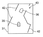
- FIGS. 4A to 4D are diagrams showing the first monitor 31 of the remote control device 13 in each state according to the first embodiment.
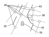
- FIG. 5 is a diagram showing the node 45 of the map information according to the first embodiment.
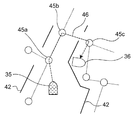
- FIG. 6 is a diagram showing a second movement path of the remote control device 13 according to the first embodiment.
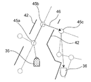
- FIG. 7 is a diagram showing a second movement route of the remote control device 13 in which the setting of the movement target position according to the first embodiment is changed.
- the second icon 35 is not moved but only the first icon 36 is moved. May. This is because, in the first embodiment, the second icon 35 on the first monitor 31 is not moved even if an autonomous avoidance operation or the like of an obstacle around the mobile device 12 is performed by the mobile device 12. It occurs because it is displayed. In this case, as shown in FIGS. 4A to 4C, by moving only the first icon 36 on the first monitor 31, as shown in FIG. 4D, between the first icon 36 and the second icon 35. , The wall 42 which is an example of an obstacle may be pinched.
- the first movement generated by the first generation unit 53 is performed. Even if the mobile device 12 autonomously moves along the route, the mobile device 12 may not be able to arrive at the movement target position.
- the first generation unit 53 of the first embodiment generates the first movement path (that is, the first movement path passing an obstacle such as the wall 42) having the shortest distance from the current position to the movement target position.
- the first movement path is the shortest movement path generated by the first generation unit 53 so as to connect the current position of the movement device 12 and the movement target position. In this case, when the moving device 12 travels along the generated first moving path, the moving device 12 repeats the avoidance operation in front of the wall 42 and can not travel further along the first moving path. is there.
- the first acquiring unit 27 is used to search for the opening 43 and pass through the opening 43 In some cases, it is possible to set a first movement route. However, when the distance (distance) between the opening 43 of the wall 42 and the moving device 12 is equal to or more than the seventh predetermined distance, it is difficult to search for the opening 43 using the first acquisition unit 27.
- the seventh predetermined distance is a distance at which environmental information can be acquired by the first acquisition unit 27, and is determined in advance by the type of sensor of the first acquisition unit 27, experimental data, or the like.
- the moving device 12 determines that the first recognition unit 23 determines that the distance ⁇ D between the current position and the movement target position is equal to or greater than the first predetermined distance.
- the node 45 included in the map information when judging, or when judging by the timer incorporated in the first recognition unit 23 that only the first predetermined time (for example, 30 seconds) has elapsed without changing the current position.
- the first generation unit 53 generates a second movement route including a route connecting nodes.
- the nodes 45 are set at least at a corner and an intersection in the passage 80P stored in the second storage unit 70, and are set at appropriate intervals in the straight portion of the passage. Then, when the mobile device 12 according to the first embodiment generates the second movement route using the node 45, the movement device 12 moves from the current position toward the movement target position by using the second movement route generated by the first generation unit 53. Make an autonomous move along.
- the moving device 12 when the distance ⁇ D between the current position and the movement target position is separated by the first predetermined distance or more, the moving device 12 according to the first embodiment has passed the first predetermined time or more without changing the current position.
- the mobile device 12 autonomously moves to the movement target position more reliably by generating the second movement route by the first generation unit 53 using the node 45 included in the map information and the connection relationship thereof. It is possible to do that.
- FIG. 5 is a diagram showing a node 45 of map information according to the first embodiment and a part of the connection relationship.
- FIG. 6 is a view showing a second movement path 46 on the map of the first monitor 31 of the remote control device 13 according to the first embodiment.
- each coordinate of the node 45 and the connection relationship between the nodes 45 are preset in the first storage unit 24 as map information.
- the information on the connection relationship between the nodes 45 is, for example, information on whether the nodes 45 are one-way or two-way, or information on costs required to travel between the nodes 45.
- the cost is an evaluation value of distance, time, energy, etc., and is an index that summarizes what is required for the mobile device 12 to move.
- the first generation unit 53 selects the node 45 with the smallest cost from the current position as the “start point node” that is the node 45 to be reached first from the current position.
- the first generation unit 53 selects the node 45 with the smallest cost to the movement target position as the “end point node” which is the final node 45 toward the movement target position. Then, based on the selected start point node and end point node, the first generation unit 53 searches for a second movement path connecting the midway node (node 45 halfway between the start point node and the end point node) at the minimum cost. .
- the algorithm used by the first generation unit 53 for searching for the second movement path can use, for example, a route search algorithm A * . In the route search algorithm A * , the first generation unit 53 searches for the second movement route while calculating the cost f (N) of the node 45 set in the traveling region of the mobile device 12.
- g (N) is the current minimum cost between the start node and the midway node.
- h (N) is an estimate of the minimum cost between the en route node and the end node.
- the route generation method such as a genetic algorithm may be used by the first generation unit 53 instead of the route search algorithm A * for searching for such an optimal second movement route.
- the first generation unit 53 of the first embodiment performs the second process from the current position of the movement device 12 to the movement target position.
- the movement path 46 is bent as shown in FIG. 6 to generate a plurality of straight lines passing through the node 45.
- the movement path 46 in FIG. 6 selects nodes as the node 45 to be passed in the order of the start point node 45a, the midway node 45b, and the end point node 45c, and uses the bending line connecting these nodes 45a, 45b and 45c as the movement path 46. There is. That is, as shown in FIG. 5, the moving device 12 according to the first embodiment moves toward the movement target position along the second movement path 46 connecting the nodes 45.
- the moving device 12 of the remote control system 11 according to the first embodiment can move from the current position to the movement target even when an environment such as the wall 42 exists between the current position of the movement device 12 and the movement target position. It can move to the position.
- the remote control device 13 according to the first embodiment the operator can remotely control the mobile device 12 without being aware of the environment around the mobile device 12.
- FIG. 7 is a view showing a second movement path 46 on the first monitor 31 of the remote control device 13 in which the setting of the movement target position according to the first embodiment is changed after the start of traveling.
- the moving device 12 moves along the moving path 46, it takes a long time for the moving device 12 to reach the moving target position since the moving target position and the current position are apart. There is a case. Therefore, in the mobile device 12 according to the first embodiment, when the second movement path 46 connecting the nodes 45a, 45b, and 45c is set by the first generation unit 53, the second movement path 46 to the end point node 45c. Are set by the first generation unit 53 and fixed. That is, in the moving apparatus 12 of the first embodiment, even when the movement target position is moved as shown in FIG. 7, the second movement path 46 is used as the first generation unit until the movement apparatus 12 reaches the end point node 45 c.
- the first movement unit 46 changes the second movement path 46 so as to move toward the latest movement target position after reaching the end point node 45 c without changing it in 53. By doing this, the first generation unit 53 does not generate the second movement route 46 which has already been generated by the first generation unit 53 each time the movement target position is set. The calculation load for generating the 2 movement path 46 can be reduced.
- moving to the end point node 45c on the second movement path 46 causes the inefficient second movement path 46 to move in a direction opposite to the movement target position. May be generated.
- a method of updating the moving path 46 by the first generation unit 53 every second predetermined time (for example, 10 seconds) or the second moving path 46 every time it reaches the node 45 on the moving path A method of updating by the first generation unit 53 is conceivable.
- the first acquisition unit 27 detects that the situation between the movement target position and the current position has changed, for example, the arrangement state of the environment around the movement device 12 has changed by a fifth predetermined distance or more.
- the movement path may be changed from the movement along the second movement path 46 to the second movement path directly toward the movement target position based on the detection information from the first acquisition unit 27.
- FIGS. 8A and 8B a series of flows of remote control of the mobile device 12 using the remote control system 11 of the first embodiment will be described using FIGS. 8A and 8B.
- step S11 of FIG. 8A the mobile device 12 determines whether the first communication unit 29 of the mobile device 12 receives the movement start signal or the destination information from the second communication unit 33 of the remote control device 13. This is judged by the first evaluation unit 73 of Twelve.
- the moving device 12 receives the movement start signal or the information on the destination (in the case of YES in step S11), the moving device 12 is selected by the first recognition unit 23 and the first generation unit 53 in step S12 of FIG. While moving 12 is started, the first generation unit 53 sets the inter-node movement flag as false (not).
- step S13 of FIG. 8A the mobile device 12 reads the movement target position received by the first communication unit 29 from the second communication unit 33 of the remote control device 13, and inputs the movement target position to the first arithmetic unit 72.
- the movement target position transmitted from the second communication unit 33 of the remote control device 13 is generated as described with reference to FIGS. 2A to 2D and FIG.
- the movement target position read out here is the movement target position immediately before stored in the temporary storage area of the first storage unit 24. However, when the movement target position is not stored in the temporary storage area and can not be read out, , The previous movement target position is used as it is.
- step S11 when the movement start signal or the information on the destination is not received (in the case of NO in step S11), the steps in FIG. 8A are performed until the first communication unit 29 of the mobile device 12 receives the information on the movement start signal or the destination. Repeat S11.
- step S14 of FIG. 8A the first calculation unit 72 of the moving apparatus 12 which has read the movement target position in step S13 calculates a distance ⁇ D between the movement target position and the current position.
- the first generation unit 53 determines whether the moving device 12 has moved on the second movement path.
- the second movement route is a movement route in the case of including the route connecting between the nodes 45 as described above. Specifically, the first generation unit 53 determines whether the inter-node movement flag is true or false.
- the inter-node movement flag is stored in the internal storage unit of the first generation unit 53. The inter-node movement flag is true when the mobile device 12 is moving on the second movement path, and when the mobile device 12 is not moving on the second movement path (for example, the mobile device 12 does not move on the first movement path It becomes false) when moving.
- step S15 since the inter-node movement flag is set to false in step S12, the case of step S15 is NO, and the process proceeds to step S16. If the inter-node movement flag is true, the result is YES in step S15, and the process proceeds to step S24.
- step S16 of FIG. 8A the first calculation unit 72 of the moving device 12 compares the movement target position with the current position.
- the first generation unit 53 determines whether the distance ⁇ D between the movement target position and the current position obtained by the first calculation unit 72 is equal to or greater than a first predetermined distance (for example, 5 m). To judge. If the first generation unit 53 determines that the distance ⁇ D is equal to or greater than the first predetermined distance (YES in step S16), the process proceeds to step S36. When the first generation unit 53 determines that the distance ⁇ D is less than the first predetermined distance (NO in step S16), the process proceeds to step S17.
- a first predetermined distance for example, 5 m
- step S17 the first generation unit 53 determines whether or not the moving device 12 can move directly from the current position to the movement target position along the first movement path.
- the process proceeds to step S18.
- the process proceeds to step S22.
- step S18 the mobile device 12 autonomously moves along the first movement path from the current position toward the movement target position by the first generation unit 53, the second control unit 26, and the drive unit 22.
- step S19 whether or not the distance ⁇ D between the movement target position and the current position is equal to or greater than a second predetermined distance (for example, 3 m), and the state where the distance ⁇ D is equal to or longer than a sixth predetermined distance is equal to or longer than a fourth predetermined time
- the first recognition unit 23 determines whether or not to continue.
- the first recognition unit 23 determines YES if the distance ⁇ D is equal to or greater than the second predetermined distance.
- step S19 the first recognition unit 23 also determines YES if the state in which the distance ⁇ D is the sixth predetermined distance or more continues for the fourth predetermined time or more.
- step S19 when the distance ⁇ D is less than the second predetermined distance and the state where the distance ⁇ D is equal to or longer than the sixth predetermined distance is less than the fourth predetermined time, the first recognition unit 23 determines NO.
- the process proceeds to step S20.
- the first recognition unit 23 determines YES in step S19, the process proceeds to step S37.
- step S37 the notification unit 75 of the remote control device 13 gives a first notification to the operator.
- the first notification is to notify the operator of the remote control device 13 that the distance between the movement target position of the moving device 12 and the current position is too far.
- the operation resistance of the operation unit 32 is increased (a resistance is applied to the joystick 32c by a motor or the like), a sound is emitted, a light is emitted, of the first icon 36
- the position is reset and displayed at the position of the second icon 35. Thereafter, the process proceeds to step S20.
- step S20 the first control unit 41 determines whether the movement stop signal is received from the second communication unit 33 of the remote control device 13 by the first communication unit 29 of the movement device 12.
- the process proceeds to step S21.
- the process returns to step S13.
- step S20 it is determined whether a movement stop signal such as an emergency stop by the operation of the operator is transmitted from the remote control device 13 to the movement device 12. Then, based on the movement stop signal, the first control unit 41 determines whether or not the movement device 12 is to be stopped.
- step S21 the autonomous movement of the mobile device 12 is stopped. After that, the series of processing ends.
- the second generation unit 74 is performed to avoid the obstacle. Avoid obstacles by creating obstacle avoidance points and moving to obstacle avoidance points.
- the process proceeds to step S23. .
- step S23 the moving device 12 is controlled by the first recognition unit 23, the first generation unit 53, the second control unit 26, the drive unit 22, and the second generation unit 74, and the second generation unit 74
- the mobile device 12 travels along the generated obstacle avoidance point. Thereafter, the process proceeds to step S19.
- steps S17 to S23 are a movement flow of the normal moving device 12 which moves the first route which is the shortest route from the current position to the movement target position.
- step S15 when the inter-node movement flag is true (when step S15 is YES), the moving device 12 is moving on the second movement route. Further, in the case where the distance ⁇ D is equal to or more than the first predetermined distance (in the case of YES at step S16), it is a case where it is determined that the moving device 12 moves the second movement path. In this case, in step S36, for the destination, a second movement route connecting the nodes is generated, and the inter-node movement flag is set to true.
- the movement target position may be set as the destination.
- step S24 the temporary target position generation unit 71 generates a temporary on the second movement route.
- the target position is set by the first evaluation unit 73. Thereafter, the process proceeds to step S25.
- step S25 the first evaluation unit 73 determines whether the moving apparatus 12 can directly move to the temporary target position on the second moving route set in step S24.
- step S25 When it is determined that the moving device 12 can directly move from the current position to the movement target position (in the case of YES at step S25), the process proceeds to step S26. If it is determined that the mobile device 12 can not move directly from the current position to the temporary target position because the obstacle is found by the first acquisition unit 27 (NO in step S25), the process proceeds to steps S33 and S34. After avoiding the obstacle in the same manner as in steps S22 and S23, the process proceeds to step S27.
- step S26 the moving device 12 moves on the second movement path from the current position to the temporary target position by the first generation unit 53, the second control unit 26, and the drive unit 22.
- step S27 as in step S19, the first recognition unit 23 is used when the distance (interval) ⁇ E between the temporary target position on the second movement route and the current position of the moving device 12 is equal to or greater than the second predetermined distance. And decide YES.
- the first recognition unit 23 also determines YES if the state in which the distance ⁇ E is equal to or longer than the sixth predetermined distance continues for the fourth predetermined time or more. That is, in step S27, when the distance ⁇ E is less than the second predetermined distance and the state where the distance ⁇ E is equal to or more than the sixth predetermined distance is less than the fourth predetermined time, the first recognition unit 23 determines NO.
- step S27 If the first recognition unit 23 determines NO in step S27, the process proceeds to step S28. If the first recognition unit 23 determines YES in step S27, the process proceeds to step S35.
- step S35 as in step S37, the notification unit 75 of the remote control device 13 performs a first notification to the operator.
- the first notification is to notify the operator of the remote control device 13 that the distance between the movement target position of the moving device 12 and the current position is too far. Thereafter, the process proceeds to step S28.
- step S28 the first recognition unit 23 determines whether the moving device 12 has approached the temporary target position to the fourth predetermined distance. If the first recognition unit 23 determines that the moving device 12 has approached the temporary target position to the fourth predetermined distance (the distance ⁇ E is equal to or less than the fourth predetermined distance) (YES in step S28), the process proceeds to step S31. When the first recognition unit 23 determines that the moving device 12 has not approached the temporary target position to the fourth predetermined distance (in the case of NO at step S28), the process proceeds to step S29. When the distance ⁇ E is equal to or less than the fourth predetermined distance, as described with reference to FIG. 6, processing for switching the movement route from the second movement route using the node 45 to the normal first movement route is performed.
- step S31 a second notification indicating return to the first movement route is performed, and the process proceeds to step S32.
- the second notification is notified in the same manner as the first notification.
- step S29 the first control unit 41 determines whether the first communication unit 29 of the mobile device 12 receives a movement stop signal from the second communication unit 33 of the remote control device 13. To judge. When it is determined that the movement stop signal is received by the first communication unit 29 of the mobile device 12 (in the case of YES at step S30), the process proceeds to step S21. When it is determined that the movement stop signal is not received by the first communication unit 29 of the mobile device 12 (in the case of NO at step S30), the process returns to step S13. In step S30, it is determined whether a movement stop signal such as an emergency stop by the operation of the operator is transmitted from the remote control device 13 to the movement device 12. Then, based on the movement stop signal, the first control unit 41 determines whether or not the movement device 12 is to be stopped.
- a movement stop signal such as an emergency stop by the operation of the operator is transmitted from the remote control device 13 to the movement device 12.
- step S32 the inter-node movement flag is set to false (no) to cancel the movement of the second movement route. Thereafter, the process proceeds to step S20.
- Steps S36 and S24 to S30 described above are the movement flows for inter-node movement of the mobile device 12, which move the second movement route connecting the nodes.
- step S13 the steps after step S13 are repeated until the movement device 12 reaches the movement target position .
- the remote control device 13 can not obtain the movement target position remotely by the operator using the operation unit 32 instead of directly operating the movement device 12 remotely. It is possible to move around the environment without depending on (a moving obstacle (for example, a moving body such as a person among the environment around the moving device 12 which is not in the map information)). Therefore, by using the remote control system 11 according to the first embodiment, the operator can remotely control the mobile apparatus 12 without being aware of environmental objects not included in the map information.
- a moving obstacle for example, a moving body such as a person among the environment around the moving device 12 which is not in the map information
- FIG. 9 is a schematic view showing the mobile apparatus 12 according to the first embodiment and the periphery thereof.
- the movement target position is set at a position away from the moving device 12
- a moving obstacle in the environment including the moving body 37 is caught between the moving device 12 and the movement target position.
- this environmental object is not included in the map information, and therefore, is not displayed on the first monitor 31. Therefore, the operator who operates the remote control device 13 can not recognize the moving body 37, and can not set the movement target position in consideration of the moving body 37.
- the mobile device 12 performs autonomous movement toward the movement target position sent from the remote control device 13 by wireless communication, and the mobile object detected by the first acquisition unit 27 Avoid 37 automatically.
- the second icon 35 is displayed on the first monitor 31 of the remote control device 13 in order to display the second icon 35 based on the recognition information of the self position of the mobile device 12 transmitted by wireless communication from the mobile device 12. Does not go straight to the first icon 36, but moves so as to bypass an empty area on the first monitor 31.
- the first storage unit 24 determines the movement target position and movement target attitude at the time of cutting, Continue to set the movement target position. In this way, even when the communication is disconnected, the mobile device 12 can continuously move to the previously set movement target position without a sudden stop.
- the movement target position includes the information on the movement target position and the movement target attitude, but even if the information on the movement target position is not included, the movement target position may be only the information on the movement target position. Good.
- the remote control device 13 can be used to efficiently move the moving device 12 to the movement target position.
- the conventional remote control system needs to set the movement target position with respect to the three-dimensional space displayed on the monitor, the distance between the surrounding environment (movement obstacles such as a wall) and the movement target position In some cases, it is difficult to intuitively determine the movement target position on the monitor.
- the distance between the surrounding environment (a moving obstacle such as a wall) and the movement target position can be intuitively grasped, and the movement target position can be easily made using the first monitor 31. It can be set to
- FIG. 10 is a view showing the first monitor 31 and the operation unit 32 of the remote control device 13 according to the second embodiment of the present invention.
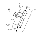
- FIG. 11 is a view showing the relationship between the first icon 36 and the wall 42 according to the second embodiment.
- the map information of the remote control device according to the second embodiment is characterized by including a movement prohibited area which prohibits the movement of the moving device 12. Then, the second arithmetic unit 77 of the remote control device 13 prohibits the setting of the movement target position in the movement prohibited area (for example, a wall, stairs, etc.) by the operation unit 32.
- the operator turns the joystick 32c forward (plus direction of the x axis) by the operator and the first icon Even if 36 is moved in the direction of the arrow, the first icon 36 does not move in the direction of the arrow in front of the wall 42. That is, the second arithmetic unit 77 can not set the position of the movement target position beyond the wall 42. At this time, the wall 42 is included in the map information as a movement prohibited line segment. Since the position of the movement target position can not be set on the wall 42 by the second arithmetic unit 77, the first icon 36 does not exceed the wall 42.
- the movement target position may not be set around the movement prohibited line segment by the second calculation unit 77. By doing this, the moving device 12 will not move near the wall 42.
- the second computing unit 77 allows the wall 42 which is also a movement inhibited line segment to be safe from the maximum radius from the rotation center of the moving device 12.
- the movement target position is not set in a predetermined distance range W to which a predetermined distance (for example, about several hundreds of mm) is added.
- the second calculation unit 77 of the remote control device 13 calculates the distance r between the center of the first icon 36 (the movement target position) and the movement prohibition line segment from the map information. Setting of movement target position is prohibited. By doing so, the moving device 12 does not approach the wall 42, and higher security can be ensured.
- FIG. 12A is a schematic view of a remote control system 61 according to a third embodiment of the present invention.
- the remote control system 61 includes at least a mobile device 62 and a remote control device 13.
- FIG. 13 is a view showing a first monitor 31 of the remote control device 13 according to the third embodiment.
- the moving apparatus 62 of 3rd Embodiment has the 1st imaging part 63 which image
- the first imaging unit 63 has cameras 63C on all sides of the vehicle body of the moving device 62, and an image forming unit 63a built in the first imaging unit 63 combines and moves images taken by the four cameras 63C.
- An image 64 viewed from above the device 62 is generated (see FIG. 12B).
- the remote control device 13 superimposes the image 64 obtained by the image forming unit 63a of the first imaging unit 63 on the map information, and displays the map information on the first monitor 31 (see FIG. 12C).
- the first icon 36 which is the movement target position is superimposed and displayed on the display range of the map.
- an area which is blocked by a wall (or an obstacle) and not photographed by the camera 63c is displayed in a black area as a wall portion 64a (or an obstacle portion 64b) as shown in FIG. 12B.
- the direction of the movement target position is displayed by an arrow icon (for example, “ ⁇ ”) or the like.
- the arrow icon is displayed as information different from the wide area map information (the right side of FIG. 12C) (displayed on the upper left side in FIG. 12C).
- the operator can set the movement target position by the operation unit 32 by acquiring the environment information around the moving device 62 not recorded in the map information by the first imaging unit 63. . That is, the operator can recognize an environmental object such as a person not recorded in the map information, and the operator can set the movement target position. Specifically, the operator can recognize the moving body 37 not recorded in the map information and set the movement target position so as to avoid the moving body 37.
- the image obtained by the first imaging unit 63 is displayed within the predetermined distance from the moving device 62 and displayed on the first monitor 31, and the movement target position (first The change of the center of the icon 36 may be limited within a predetermined distance from the same moving device 62 as the image 64 displayed on the first monitor 31.
- the operator is not recorded in the map information by performing control so that the movement target position (center of the first icon 36) can not be set outside the range of the image 64 displayed on the first monitor 31 illustrated in FIG.
- An appropriate movement target position is set without setting the movement target position on the movement obstacle of the surrounding environment.
- the change of the movement target position may be limited within a predetermined distance from the movement device 62 regardless of the image. By limiting the change position of the movement target position within a predetermined distance, the movement target position is not largely separated from the moving device 62. Specifically, as one example, it is desirable to set the width within 2 m, which is the same as the width of the passage 80P.
- the coordinates of the destination to which the moving device 62 frequently travels may be stored in advance in the first storage unit 24 and the third storage unit 34, and the first list selection unit 76 may be provided in the remote control device 13. .
- the first list selection unit 76 lists the destinations associated with the storage units 24 and 34 as a destination list on the operation screen of the first monitor 31 of the remote control device 13 as shown in FIG. 12D. indicate.
- the first list selection unit 76 reads the coordinates of the selected destination from the storage units 24 and 34, and the movement route is The movement of the mobile device 12 can also be started by the generation unit 53.
- FIG. 14 is a view showing a first monitor 31 of the remote control system 11 according to the fourth embodiment of the present invention.
- the image forming unit 31 a of the remote control device 13 always displays the attitude of the first icon 36 in a fixed direction on the first monitor 31.
- the traveling direction of the first icon 36 is always upward of the first monitor 31. Since the first icon 36 is always displayed above the first monitor 31 by the image forming unit 31 a, the operation direction of the joystick 32 c matches the direction of the first icon 36. As a result, the operator can easily grasp the moving target posture at the moving target position, and can easily set the moving target position.
- the remote control system according to the present invention is easy to operate and is useful for a remote control system of a communication robot.
Abstract
Description
図1は、本発明の第1実施形態にかかる遠隔制御システム11の模式図である。第1実施形態の遠隔制御システム11は、移動装置12及び遠隔制御装置13から少なくとも構成されるシステムである。第1実施形態の遠隔制御システム11は、遠隔制御装置13からの移動目標位置に基づいて、移動装置12が自律移動するシステムである。ここで、移動経路(第1移動経路、第2移動経路)とは、移動装置12が自律移動するために第1生成部53で生成された経路を意味する。移動装置12は、移動目標位置までの周囲の環境情報を取得しながら第1生成部53で移動経路を生成し、この移動経路に沿って、例えば駆動輪22a又は脚などの駆動部を駆動させて自律移動し、移動目標位置に対して追従移動する。 First Embodiment
FIG. 1 is a schematic view of a
ここで、移動装置12の初期値が設定された後であれば、第1アイコン36の位置は、第2アイコン35の位置より、移動装置12の走行方向に距離dXだけ離れた位置である(図2B参照)。移動装置12は、遠隔制御装置13の第2通信部33から送信された新たな移動目標位置を第1通信部29で受信すると、第1制御部41での制御に基づいて、この新たな移動目標位置に向って自律的に移動を開始する。図2Bに示す場合は、移動装置12は、第1アイコン36が設定された移動装置12の前進方向に直進移動する。 As shown in FIG. 2B, when the
Here, if the initial value of the moving
図10は、本発明の第2実施形態にかかる遠隔制御装置13の第1モニタ31及び操作部32を示す図である。図11は、第2実施形態にかかる第1アイコン36と壁42との関係を示す図である。 Second Embodiment
FIG. 10 is a view showing the
図12Aは、本発明の第3実施形態にかかる遠隔制御システム61の模式図である。遠隔制御システム61は、移動装置62と遠隔制御装置13とを少なくとも含んで構成される。図13は、第3実施形態にかかる遠隔制御装置13の第1モニタ31を示す図である。 Third Embodiment
FIG. 12A is a schematic view of a
図14は、本発明の第4実施形態にかかる遠隔制御システム11の第1モニタ31を示す図である。 Fourth Embodiment
FIG. 14 is a view showing a
Claims (11)
- 移動装置及び遠隔制御装置から構成される遠隔制御システムであって、
前記遠隔制御装置は、操作部と、前記操作部により入力された移動目標位置を前記移動装置へ送信する通信部と、前記操作部の入力値を変化量として検出する検出部と、を有し、
前記移動装置は、地図情報を記憶する記憶部と、移動経路に沿って前記移動目標位置へ自律移動する制御部と、前記変化量に応じて前記移動目標位置を変更させながら自律移動する制御部と、を有する、
遠隔制御システム。 A remote control system comprising a mobile device and a remote control device, comprising:
The remote control device includes an operation unit, a communication unit that transmits the movement target position input by the operation unit to the moving device, and a detection unit that detects an input value of the operation unit as a change amount. ,
The moving device includes a storage unit storing map information, a control unit autonomously moving to the movement target position along a movement path, and a control unit autonomously moving while changing the movement target position according to the change amount And have,
Remote control system. - 前記移動装置の前記制御部は、前記移動装置の現在位置に前記操作部による前記変化量を加算して移動目標位置を求める、
請求項1に記載の遠隔制御システム。 The control unit of the movement device adds the amount of change by the operation unit to the current position of the movement device to obtain a movement target position.
The remote control system according to claim 1. - 前記遠隔制御装置は、前記移動装置の現在位置と前記移動目標位置との距離が所定距離以上離れた場合、又は、前記移動目標位置に所定時間以上の間に前記移動装置が到達しない場合に、報知を行う報知部をさらに備える、
請求項1に記載の遠隔制御システム。 When the distance between the current position of the moving device and the movement target position is separated by a predetermined distance or more, or when the movement device does not reach the movement target position during a predetermined time or more, the remote control device may The information processing apparatus further comprising a notification unit that performs notification
The remote control system according to claim 1. - 前記移動装置の前記制御部は、前記移動装置の現在位置と前記移動目標位置との距離が所定距離以上だけ離れた場合、又は、前記移動目標位置に所定時間以上の間に到達しない場合に、前記地図情報に含まれるノードの接続関係に基づいて前記現在位置と前記移動目標位置とを結ぶ移動経路を生成する生成部をさらに備える、
請求項1又は2に記載の遠隔制御システム。 When the distance between the current position of the moving device and the movement target position is separated by a predetermined distance or more, or when the control unit of the movement device does not reach the movement target position for a predetermined time or more, And a generation unit configured to generate a movement route connecting the current position and the movement target position based on a connection relation of nodes included in the map information.
A remote control system according to claim 1 or 2. - 前記生成部は、前記移動装置が前記移動経路に沿って自律移動を始めた場合に、前記ノード間を結ぶ移動経路を固定する、
請求項4に記載の遠隔制御システム。 The generation unit fixes a movement path connecting between the nodes when the mobile device starts an autonomous movement along the movement path.
The remote control system according to claim 4. - 前記遠隔制御装置は、前記移動装置の現在位置を示す移動装置アイコン及び前記移動目標位置を示す移動目標位置アイコンを前記地図情報に重ねて表示するモニタ、をさらに備える、
請求項1又は2に記載の遠隔制御システム。 The remote control device further includes a mobile device icon indicating the current position of the mobile device, and a monitor that displays a moving target position icon indicating the moving target position superimposed on the map information.
A remote control system according to claim 1 or 2. - 前記遠隔制御部は、前記地図情報に含まれる移動禁止領域に前記移動目標位置を設定することを禁止している、
請求項1又は2に記載の遠隔制御システム。 The remote control unit prohibits the setting of the movement target position in the movement prohibited area included in the map information.
A remote control system according to claim 1 or 2. - 前記移動禁止領域は、前記地図情報に含まれる壁である、
請求項7に記載の遠隔制御システム。 The movement prohibited area is a wall included in the map information.
The remote control system according to claim 7. - 前記移動装置は、周囲を撮影する撮影部を有し、
前記遠隔制御装置は、前記撮影部で撮影された画像を前記地図情報に重ねて前記モニタに表示する、
請求項6に記載の遠隔制御システム。 The moving device has a photographing unit for photographing the surroundings,
The remote control device superimposes the image captured by the imaging unit on the map information and displays the image on the monitor.
The remote control system according to claim 6. - 前記移動装置の車体の四方に配置された撮影部と、
前記撮影部で取得した画像を合成して前記移動装置の上方から見た画像を生成する画像形成部と、
前記遠隔制御部に配置されかつ前記画像形成部で形成した画像を表示するモニタとをさらに備える、
請求項1又は2に記載の遠隔制御システム。 An imaging unit disposed on each side of a vehicle body of the moving device;
An image forming unit that combines the images acquired by the imaging unit to generate an image viewed from above the moving device;
And a monitor disposed in the remote control unit and displaying an image formed by the image forming unit.
A remote control system according to claim 1 or 2. - 前記遠隔制御部は、前記移動目標位置アイコンの姿勢を、前記モニタ上で常に所定の方向に固定して表示する、
請求項6に記載の遠隔制御システム。 The remote control unit always displays the posture of the movement target position icon fixedly in a predetermined direction on the monitor.
The remote control system according to claim 6.
Priority Applications (3)
| Application Number | Priority Date | Filing Date | Title |
|---|---|---|---|
| US14/355,343 US20140297066A1 (en) | 2011-11-04 | 2012-11-01 | Remote control system |
| JP2013541634A JP5828088B2 (en) | 2011-11-04 | 2012-11-01 | Remote control system |
| EP12846550.7A EP2775365A4 (en) | 2011-11-04 | 2012-11-01 | Remote control system |
Applications Claiming Priority (2)
| Application Number | Priority Date | Filing Date | Title |
|---|---|---|---|
| JP2011-241892 | 2011-11-04 | ||
| JP2011241892 | 2011-11-04 |
Publications (1)
| Publication Number | Publication Date |
|---|---|
| WO2013065312A1 true WO2013065312A1 (en) | 2013-05-10 |
Family
ID=48191684
Family Applications (1)
| Application Number | Title | Priority Date | Filing Date |
|---|---|---|---|
| PCT/JP2012/007019 WO2013065312A1 (en) | 2011-11-04 | 2012-11-01 | Remote control system |
Country Status (4)
| Country | Link |
|---|---|
| US (1) | US20140297066A1 (en) |
| EP (1) | EP2775365A4 (en) |
| JP (1) | JP5828088B2 (en) |
| WO (1) | WO2013065312A1 (en) |
Cited By (7)
| Publication number | Priority date | Publication date | Assignee | Title |
|---|---|---|---|---|
| JP2014229300A (en) * | 2013-05-17 | 2014-12-08 | 恩斯邁電子(深▲しん▼)有限公司Msi Computer (Shenzhen) Co.,Ltd. | Mobile device |
| WO2015087430A1 (en) * | 2013-12-12 | 2015-06-18 | 日立建機株式会社 | Vehicle travel system and vehicle travel control method |
| JP2019133701A (en) * | 2019-04-01 | 2019-08-08 | ヤンマー株式会社 | Travel area shape registration system |
| JP2021036451A (en) * | 2014-04-25 | 2021-03-04 | ソニー株式会社 | Information processor, information processing method, and information processing program |
| JP2022040377A (en) * | 2020-06-15 | 2022-03-10 | ソニーグループ株式会社 | Control method and control device |
| JP2022065749A (en) * | 2020-10-16 | 2022-04-28 | 株式会社キビテク | Control system for movable body |
| US11927960B2 (en) | 2014-10-17 | 2024-03-12 | Sony Group Corporation | Control device, control method, and computer program |
Families Citing this family (2)
| Publication number | Priority date | Publication date | Assignee | Title |
|---|---|---|---|---|
| CN105787463A (en) * | 2016-03-18 | 2016-07-20 | 哈尔滨工程大学 | Wi-Fi-based remote target tracking system and method |
| JPWO2020039656A1 (en) * | 2018-08-23 | 2020-08-27 | 日本精工株式会社 | Self-propelled device, traveling control method of self-propelled device, and traveling control program |
Citations (6)
| Publication number | Priority date | Publication date | Assignee | Title |
|---|---|---|---|---|
| JPH0854925A (en) * | 1994-08-09 | 1996-02-27 | Yamaha Motor Co Ltd | Unmanned vehicle |
| JPH11149315A (en) * | 1997-11-19 | 1999-06-02 | Mitsubishi Heavy Ind Ltd | Robot control system |
| JP2001116567A (en) * | 1999-10-20 | 2001-04-27 | Matsushita Electric Ind Co Ltd | On-vehicle driving supporting information displaying device |
| JP2003532218A (en) | 2000-05-01 | 2003-10-28 | アイロボット コーポレーション | Method and system for remotely controlling a mobile robot |
| JP3844247B2 (en) | 2003-07-28 | 2006-11-08 | 松下電工株式会社 | Route generating apparatus for autonomous movement and autonomous mobile apparatus using the apparatus |
| JP2010169692A (en) * | 2010-04-08 | 2010-08-05 | Kyocera Corp | Mobile map display device and display control method of the same |
Family Cites Families (6)
| Publication number | Priority date | Publication date | Assignee | Title |
|---|---|---|---|---|
| US7474945B2 (en) * | 2004-12-14 | 2009-01-06 | Honda Motor Company, Ltd. | Route generating system for an autonomous mobile robot |
| US7539557B2 (en) * | 2005-12-30 | 2009-05-26 | Irobot Corporation | Autonomous mobile robot |
| IL183006A0 (en) * | 2007-05-06 | 2007-12-03 | Wave Group Ltd | A bilateral robotic omni-directional situational awarness system having a smart throw able transportaion case |
| US8032296B2 (en) * | 2008-04-30 | 2011-10-04 | Verizon Patent And Licensing Inc. | Method and system for providing video mapping and travel planning services |
| JP5124351B2 (en) * | 2008-06-04 | 2013-01-23 | 三洋電機株式会社 | Vehicle operation system |
| US8392065B2 (en) * | 2008-09-11 | 2013-03-05 | Deere & Company | Leader-follower semi-autonomous vehicle with operator on side |
-
2012
- 2012-11-01 JP JP2013541634A patent/JP5828088B2/en active Active
- 2012-11-01 WO PCT/JP2012/007019 patent/WO2013065312A1/en active Application Filing
- 2012-11-01 US US14/355,343 patent/US20140297066A1/en not_active Abandoned
- 2012-11-01 EP EP12846550.7A patent/EP2775365A4/en not_active Withdrawn
Patent Citations (6)
| Publication number | Priority date | Publication date | Assignee | Title |
|---|---|---|---|---|
| JPH0854925A (en) * | 1994-08-09 | 1996-02-27 | Yamaha Motor Co Ltd | Unmanned vehicle |
| JPH11149315A (en) * | 1997-11-19 | 1999-06-02 | Mitsubishi Heavy Ind Ltd | Robot control system |
| JP2001116567A (en) * | 1999-10-20 | 2001-04-27 | Matsushita Electric Ind Co Ltd | On-vehicle driving supporting information displaying device |
| JP2003532218A (en) | 2000-05-01 | 2003-10-28 | アイロボット コーポレーション | Method and system for remotely controlling a mobile robot |
| JP3844247B2 (en) | 2003-07-28 | 2006-11-08 | 松下電工株式会社 | Route generating apparatus for autonomous movement and autonomous mobile apparatus using the apparatus |
| JP2010169692A (en) * | 2010-04-08 | 2010-08-05 | Kyocera Corp | Mobile map display device and display control method of the same |
Non-Patent Citations (1)
| Title |
|---|
| See also references of EP2775365A4 |
Cited By (15)
| Publication number | Priority date | Publication date | Assignee | Title |
|---|---|---|---|---|
| JP2014229300A (en) * | 2013-05-17 | 2014-12-08 | 恩斯邁電子(深▲しん▼)有限公司Msi Computer (Shenzhen) Co.,Ltd. | Mobile device |
| WO2015087430A1 (en) * | 2013-12-12 | 2015-06-18 | 日立建機株式会社 | Vehicle travel system and vehicle travel control method |
| CN105518556A (en) * | 2013-12-12 | 2016-04-20 | 日立建机株式会社 | Vehicle travel system and vehicle travel control method |
| JPWO2015087430A1 (en) * | 2013-12-12 | 2017-03-16 | 日立建機株式会社 | Vehicle traveling system and vehicle traveling control method |
| US10048692B2 (en) | 2013-12-12 | 2018-08-14 | Hitachi Construction Machinery Co., Ltd. | Vehicle travel system |
| JP2021036451A (en) * | 2014-04-25 | 2021-03-04 | ソニー株式会社 | Information processor, information processing method, and information processing program |
| US11237560B2 (en) | 2014-04-25 | 2022-02-01 | Sony Corporation | Control device, imaging device, control method, imaging method, and computer program |
| JP7078093B2 (en) | 2014-04-25 | 2022-05-31 | ソニーグループ株式会社 | Information processing equipment, information processing methods and information processing programs |
| JP2022111131A (en) * | 2014-04-25 | 2022-07-29 | ソニーグループ株式会社 | Flight control method, information processing apparatus and computer program |
| US11927960B2 (en) | 2014-10-17 | 2024-03-12 | Sony Group Corporation | Control device, control method, and computer program |
| JP2019133701A (en) * | 2019-04-01 | 2019-08-08 | ヤンマー株式会社 | Travel area shape registration system |
| JP7142597B2 (en) | 2019-04-01 | 2022-09-27 | ヤンマーパワーテクノロジー株式会社 | Running area shape registration system |
| JP2022040377A (en) * | 2020-06-15 | 2022-03-10 | ソニーグループ株式会社 | Control method and control device |
| JP7392742B2 (en) | 2020-06-15 | 2023-12-06 | ソニーグループ株式会社 | Control method and control device |
| JP2022065749A (en) * | 2020-10-16 | 2022-04-28 | 株式会社キビテク | Control system for movable body |
Also Published As
| Publication number | Publication date |
|---|---|
| US20140297066A1 (en) | 2014-10-02 |
| EP2775365A4 (en) | 2015-09-30 |
| EP2775365A1 (en) | 2014-09-10 |
| JP5828088B2 (en) | 2015-12-02 |
| JPWO2013065312A1 (en) | 2015-04-02 |
Similar Documents
| Publication | Publication Date | Title |
|---|---|---|
| WO2013065312A1 (en) | Remote control system | |
| JP3906743B2 (en) | Guide robot | |
| JP5550671B2 (en) | Autonomous traveling robot and traveling control method for autonomous traveling robot | |
| JP5768273B2 (en) | A robot that predicts a pedestrian's trajectory and determines its avoidance behavior | |
| JP5366711B2 (en) | Semi-autonomous vehicle remote control system | |
| JP2006185438A (en) | Robot control device | |
| US20050212680A1 (en) | Self-propelled cleaner | |
| JP5946428B2 (en) | Mobile robot system | |
| EP2237127B1 (en) | Target route setting support system | |
| JP2006113858A (en) | Method and system for supporting remote operation for mobile object | |
| JP2010231698A (en) | Network robot system, and robot control device, method and program | |
| JP2007260822A (en) | Guide robot | |
| JP2005239048A (en) | Parking assistance system | |
| JP7312582B2 (en) | unmanned mobile device | |
| JP4910787B2 (en) | Parking assistance device and method, parking position setting device and method, recording medium, and program | |
| CN110554692A (en) | Map information updating system | |
| JP5187757B2 (en) | Unmanned mobile system | |
| JP2019196065A (en) | Automatic parking control device and automatic parking control system | |
| JP2018112775A (en) | Autonomous Mobile Robot | |
| JP2008134744A (en) | Autonomous moving device group control system | |
| CN113576854A (en) | Information processor | |
| JP5024896B2 (en) | Mobile robot control system | |
| JP2006139525A (en) | Autonomous mobile robot | |
| JP2007286740A (en) | Autonomous movable body | |
| JP2011000656A (en) | Guide robot |
Legal Events
| Date | Code | Title | Description |
|---|---|---|---|
| 121 | Ep: the epo has been informed by wipo that ep was designated in this application |
Ref document number: 12846550 Country of ref document: EP Kind code of ref document: A1 |
|
| ENP | Entry into the national phase |
Ref document number: 2013541634 Country of ref document: JP Kind code of ref document: A |
|
| REEP | Request for entry into the european phase |
Ref document number: 2012846550 Country of ref document: EP |
|
| WWE | Wipo information: entry into national phase |
Ref document number: 14355343 Country of ref document: US Ref document number: 2012846550 Country of ref document: EP |
|
| NENP | Non-entry into the national phase |
Ref country code: DE |