WO2008036304A2 - Systems, devices, and methods for surgery on a hollow anatomically suspended organ - Google Patents
Systems, devices, and methods for surgery on a hollow anatomically suspended organ Download PDFInfo
- Publication number
- WO2008036304A2 WO2008036304A2 PCT/US2007/020281 US2007020281W WO2008036304A2 WO 2008036304 A2 WO2008036304 A2 WO 2008036304A2 US 2007020281 W US2007020281 W US 2007020281W WO 2008036304 A2 WO2008036304 A2 WO 2008036304A2
- Authority
- WO
- WIPO (PCT)
- Prior art keywords
- robot
- robotic
- cannula
- eye
- serial
- Prior art date
Links
Classifications
-
- A—HUMAN NECESSITIES
- A61—MEDICAL OR VETERINARY SCIENCE; HYGIENE
- A61B—DIAGNOSIS; SURGERY; IDENTIFICATION
- A61B17/00—Surgical instruments, devices or methods, e.g. tourniquets
-
- A—HUMAN NECESSITIES
- A61—MEDICAL OR VETERINARY SCIENCE; HYGIENE
- A61B—DIAGNOSIS; SURGERY; IDENTIFICATION
- A61B90/00—Instruments, implements or accessories specially adapted for surgery or diagnosis and not covered by any of the groups A61B1/00 - A61B50/00, e.g. for luxation treatment or for protecting wound edges
- A61B90/10—Instruments, implements or accessories specially adapted for surgery or diagnosis and not covered by any of the groups A61B1/00 - A61B50/00, e.g. for luxation treatment or for protecting wound edges for stereotaxic surgery, e.g. frame-based stereotaxis
- A61B90/14—Fixators for body parts, e.g. skull clamps; Constructional details of fixators, e.g. pins
- A61B90/16—Bite blocks
-
- A—HUMAN NECESSITIES
- A61—MEDICAL OR VETERINARY SCIENCE; HYGIENE
- A61B—DIAGNOSIS; SURGERY; IDENTIFICATION
- A61B3/00—Apparatus for testing the eyes; Instruments for examining the eyes
- A61B3/10—Objective types, i.e. instruments for examining the eyes independent of the patients' perceptions or reactions
- A61B3/13—Ophthalmic microscopes
-
- A—HUMAN NECESSITIES
- A61—MEDICAL OR VETERINARY SCIENCE; HYGIENE
- A61B—DIAGNOSIS; SURGERY; IDENTIFICATION
- A61B34/00—Computer-aided surgery; Manipulators or robots specially adapted for use in surgery
- A61B34/30—Surgical robots
- A61B34/35—Surgical robots for telesurgery
-
- A—HUMAN NECESSITIES
- A61—MEDICAL OR VETERINARY SCIENCE; HYGIENE
- A61B—DIAGNOSIS; SURGERY; IDENTIFICATION
- A61B34/00—Computer-aided surgery; Manipulators or robots specially adapted for use in surgery
- A61B34/30—Surgical robots
- A61B34/37—Master-slave robots
-
- A—HUMAN NECESSITIES
- A61—MEDICAL OR VETERINARY SCIENCE; HYGIENE
- A61B—DIAGNOSIS; SURGERY; IDENTIFICATION
- A61B34/00—Computer-aided surgery; Manipulators or robots specially adapted for use in surgery
- A61B34/70—Manipulators specially adapted for use in surgery
-
- A—HUMAN NECESSITIES
- A61—MEDICAL OR VETERINARY SCIENCE; HYGIENE
- A61B—DIAGNOSIS; SURGERY; IDENTIFICATION
- A61B34/00—Computer-aided surgery; Manipulators or robots specially adapted for use in surgery
- A61B34/70—Manipulators specially adapted for use in surgery
- A61B34/71—Manipulators operated by drive cable mechanisms
-
- A—HUMAN NECESSITIES
- A61—MEDICAL OR VETERINARY SCIENCE; HYGIENE
- A61B—DIAGNOSIS; SURGERY; IDENTIFICATION
- A61B34/00—Computer-aided surgery; Manipulators or robots specially adapted for use in surgery
- A61B34/70—Manipulators specially adapted for use in surgery
- A61B34/75—Manipulators having means for prevention or compensation of hand tremors
-
- A—HUMAN NECESSITIES
- A61—MEDICAL OR VETERINARY SCIENCE; HYGIENE
- A61B—DIAGNOSIS; SURGERY; IDENTIFICATION
- A61B34/00—Computer-aided surgery; Manipulators or robots specially adapted for use in surgery
- A61B34/70—Manipulators specially adapted for use in surgery
- A61B34/76—Manipulators having means for providing feel, e.g. force or tactile feedback
-
- A—HUMAN NECESSITIES
- A61—MEDICAL OR VETERINARY SCIENCE; HYGIENE
- A61B—DIAGNOSIS; SURGERY; IDENTIFICATION
- A61B17/00—Surgical instruments, devices or methods, e.g. tourniquets
- A61B2017/00831—Material properties
- A61B2017/00867—Material properties shape memory effect
-
- A—HUMAN NECESSITIES
- A61—MEDICAL OR VETERINARY SCIENCE; HYGIENE
- A61B—DIAGNOSIS; SURGERY; IDENTIFICATION
- A61B17/00—Surgical instruments, devices or methods, e.g. tourniquets
- A61B17/34—Trocars; Puncturing needles
- A61B17/3403—Needle locating or guiding means
- A61B2017/3405—Needle locating or guiding means using mechanical guide means
- A61B2017/3407—Needle locating or guiding means using mechanical guide means including a base for support on the body
-
- A—HUMAN NECESSITIES
- A61—MEDICAL OR VETERINARY SCIENCE; HYGIENE
- A61B—DIAGNOSIS; SURGERY; IDENTIFICATION
- A61B34/00—Computer-aided surgery; Manipulators or robots specially adapted for use in surgery
- A61B34/30—Surgical robots
- A61B2034/304—Surgical robots including a freely orientable platform, e.g. so called 'Stewart platforms'
-
- A—HUMAN NECESSITIES
- A61—MEDICAL OR VETERINARY SCIENCE; HYGIENE
- A61B—DIAGNOSIS; SURGERY; IDENTIFICATION
- A61B90/00—Instruments, implements or accessories specially adapted for surgery or diagnosis and not covered by any of the groups A61B1/00 - A61B50/00, e.g. for luxation treatment or for protecting wound edges
- A61B90/06—Measuring instruments not otherwise provided for
- A61B2090/064—Measuring instruments not otherwise provided for for measuring force, pressure or mechanical tension
-
- A—HUMAN NECESSITIES
- A61—MEDICAL OR VETERINARY SCIENCE; HYGIENE
- A61B—DIAGNOSIS; SURGERY; IDENTIFICATION
- A61B90/00—Instruments, implements or accessories specially adapted for surgery or diagnosis and not covered by any of the groups A61B1/00 - A61B50/00, e.g. for luxation treatment or for protecting wound edges
- A61B90/30—Devices for illuminating a surgical field, the devices having an interrelation with other surgical devices or with a surgical procedure
- A61B2090/306—Devices for illuminating a surgical field, the devices having an interrelation with other surgical devices or with a surgical procedure using optical fibres
-
- A—HUMAN NECESSITIES
- A61—MEDICAL OR VETERINARY SCIENCE; HYGIENE
- A61B—DIAGNOSIS; SURGERY; IDENTIFICATION
- A61B34/00—Computer-aided surgery; Manipulators or robots specially adapted for use in surgery
- A61B34/30—Surgical robots
-
- A—HUMAN NECESSITIES
- A61—MEDICAL OR VETERINARY SCIENCE; HYGIENE
- A61B—DIAGNOSIS; SURGERY; IDENTIFICATION
- A61B90/00—Instruments, implements or accessories specially adapted for surgery or diagnosis and not covered by any of the groups A61B1/00 - A61B50/00, e.g. for luxation treatment or for protecting wound edges
- A61B90/20—Surgical microscopes characterised by non-optical aspects
-
- A—HUMAN NECESSITIES
- A61—MEDICAL OR VETERINARY SCIENCE; HYGIENE
- A61F—FILTERS IMPLANTABLE INTO BLOOD VESSELS; PROSTHESES; DEVICES PROVIDING PATENCY TO, OR PREVENTING COLLAPSING OF, TUBULAR STRUCTURES OF THE BODY, e.g. STENTS; ORTHOPAEDIC, NURSING OR CONTRACEPTIVE DEVICES; FOMENTATION; TREATMENT OR PROTECTION OF EYES OR EARS; BANDAGES, DRESSINGS OR ABSORBENT PADS; FIRST-AID KITS
- A61F9/00—Methods or devices for treatment of the eyes; Devices for putting-in contact lenses; Devices to correct squinting; Apparatus to guide the blind; Protective devices for the eyes, carried on the body or in the hand
- A61F9/007—Methods or devices for eye surgery
Definitions
- ophthalmic microsurgery presents medical professionals with unique challenges. Focusing on ophthalmic microsurgery, these challenges stem from the fact that the eye is a hollow and movable organ requiring very accurate and delicate surgical tasks to be performed inside it.
- medical professionals use a microscope to visualize the retina by looking through the dilated iris.
- the tools currently used by medical professionals lack intraocular dexterity and are constrained to minimal degrees of freedom. Hence, it can be very difficult to perform complex ophthalmic surgery.
- medical professionals can also be required to rotate the eye under the microscope in order to allow access to and visualization of the peripheral regions of the eye while manipulating multiple tools with very high precision.
- microsurgery challenges include lack of intraocular dexterity of the tools, limited force feedback, and lack of depth perception when visualizing using the microscope.
- Microsurgery also demands a level of accuracy and bimanual dexterity not common to other surgical fields (e.g. positioning accuracy of 5-10 microns can be required). These difficult and precise bimanual tasks demonstrate the potential benefits and need for robotic assistance.
- a tele-robotic microsurgical system for eye surgery has: a tele-robotic master and a slave hybrid-robot; wherein the tele-robotic master has at least two master slave interfaces controlled by a medical professional; wherein the slave hybrid-robot has at least two robotic arms attached to a frame which is releasably attachable to a patient's head; and wherein the at least two robotic arms each have a parallel robot and a serial robot.
- a tele-robotic microsurgical system for eye surgery has: a frame, a first robotic arm, a second robotic arm, and a tele-robotic master; wherein the frame is releasably attached to a patient's head; wherein the first robotic arm and second robotic arm each have a parallel robot and a serial robot; the tele-robotic master having a master slave interface controlled by a medical professional and the serial robot having a tube and a cannula.
- a tele-robotic microsurgical system for surgery on a hollow anatomically suspended organ has: a tele-robotic master and a slave hybrid-robot; wherein the tele-robotic master has at least one master slave interface controlled by a medical professional; wherein the slave hybrid-robot has at least one robotic arm attached to a frame releasably attachable to a patient; and wherein the at least one robotic arm has a parallel robot and a serial robot.
- a slave-hybrid robot for surgery on a hollow anatomically suspended organ has: a frame releasably attachable to a patient and at least one robotic arm releasably attached to the frame; wherein the at least one robotic arm has a parallel robot and a serial robot; wherein the serial robot has a tube for delivering a pre-bent NiTi cannula; wherein at least one of the tube and the pre-bent NiTi cannula is capable of rotating about its longitudinal axis; and wherein the pre-bent NiTi cannula is capable of bending when extended from the tube.
- FIG. IA illustratively displays a method for using a tele-robotic microsurgery system in accordance with some embodiments of the disclosed subject matter
- FIG. IB illustratively displays the general surgical setup for tele-robotic microsurgery on the eye in accordance with some embodiments of the disclosed subject matter
- FIG. 2 illustratively displays a slave hybrid-robot positioned over a patient's head in accordance with some embodiments of the disclosed subject matter
- FIG. 3 illustratively displays a tele-robotic microsurgical system for eye surgery including a tele-robotic master and a slave hybrid-robot in accordance with some embodiments of the disclosed subject matter;
- FIG. 4A illustratively displays a slave hybrid-robot illustrating a serial robot and a parallel robot in accordance with some embodiments of the disclosed subject matter
- FIGS. 4B-4C illustratively display a serial connector included in a serial robot in accordance with some embodiments of the disclosed subject matter
- FIG. 5 illustratively displays a serial articulator included in a serial robot in accordance with some embodiments of the disclosed subject matter
- FIGS. 6A-6B illustratively display a tube for delivering a cannula in accordance with some embodiments of the disclosed subject matter
- FIG. 7 illustratively displays a slave hybrid-robot illustrating the legs of a parallel robot in accordance with some embodiments of the disclosed subject matter
- FIGS. 8-9 illustratively display an eye and an i th slave hybrid-robot in accordance with some embodiments of the disclosed subject matter.
- FIGS. 10A-10B illustratively display an organ and an i th slave hybrid-robot in accordance with some embodiments of the disclosed subject matter.
- a tele-robotic microsurgical system can have a slave hybrid robot having at least two robotic arms (each robotic arm having a serial robot attached to a parallel robot) and a tele-robotic master having at least two user controlled master slave interfaces (e.g., joysticks).
- the serial robot for each robotic arm can have a tube housing a pre-bent NiTi cannula that is substantially straight when in the tube.
- the user can control movement of the at least two robotic arms by controlling the parallel robot and serial robot for each robotic arm. That is, the user can control the combined motion of the serial robot and parallel robot for each arm by the master slave interfaces.
- a general surgical setup for eye surgery 100 includes a surgical bed 110, a surgical microscope 120, a slave hybrid-robot 125, and a tele- robotic master (not shown).
- the patient lies on surgical bed 110, with his head 115 positioned as shown.
- a patient located on surgical bed 110 has a frame 130 releasably attached to their head, and a slave hybrid-robot releasably attached to frame 130.
- a medical professional can look into the patient's eye through surgical microscope 120 and can control drug delivery, aspiration, light delivery, and delivery of at least one of microgrippers, picks, and micro knives by the tele-robotic master which is in communication with slave hybrid-robot 125.
- the slave-hybrid robot can be positioned over the organ (e.g., attached to a frame connected to the head of a patient).
- the slave-hybrid robot having a first robotic arm (having a first parallel robot and first serial robot) and a second robotic arm (having a second parallel robot and a second serial robot) can have both arms in a position minimizing the amount of movement needed to enter the organ.
- the user can insert a first tube, housing a first pre- bent NiTi cannula, into a patient's organ by moving the first parallel robot.
- a second user controlled master slave interface to control the second robotic arm the user can insert a second tube into the patient's organ by moving the second parallel robot.
- surgical tasks 103 in Figure 1 A), such as organ manipulation (105 in Figure IA) and operations inside the organ (104 in Figure IA).
- Organ manipulation (105 in Figure I A) and operations inside the organ (104 in Figure IA) can occur in series (e.g., operations inside the organ then organ manipulation, organ manipulation then operations inside the organ, etc.) or in parallel (e.g., operations inside the organ and organ manipulation at substantially the same time).
- the user can use the first serial robot to rotate at least one of the first pre-bent NiTi cannula and the first tube about their longitudinal axis (hence positioning the NiTi cannula inside the organ). This rotation about the longitudinal axis represents a second degree of freedom for the serial robot.
- the user can use the second serial robot to move a second pre-bent NiTi cannula out of the second tube. The second pre-bent NiTi cannula bends as it exits the second tube.
- the user can rotate at least one of the second pre-bent NiTi cannula and the second tube about their longitudinal axis.
- delivering a second pre-bent NiTi cannula out of the tube is not necessary.
- the second tube can be used for delivering a light into the organ.
- the pre-bent NiTi cannula can be delivered outside of the tube to provide a controlled delivery of light through an embedded optical fiber.
- the pre-bent NiTi cannula can be delivered outside of the tube to provide a controlled delivery of an optical fiber bundle for controllable intra-ocular visualization for applications such as visualizing the distance between tools and the retina by providing a side view to the surgeon.
- the user can utilize at least one of the first and second NiTi cannula and first and second tubes for drug delivery, aspiration, light delivery, and delivery of at least one of microgrippers, picks, and micro knives into the organ.
- the user can manipulate and position the organ (105 in Figure IA), with both tubes in the patient's organ,.
- the user can move both parallel robots together (hence moving the tubes in the organ) and manipulate the organ.
- the user can perform additional operations within the organ (104 in Figure IA).
- the user For exiting the organ (106 in Figure IA) 5 that is, to remove the surgical instruments from the organ, the user uses the first, user controlled master slave interface to control the first robotic arm.
- the user retracts the first pre-bent NiTi cannula into the first tube using the first serial robot.
- the user can similarly retract the second pre-bent NiTi cannula into the second tube using the serial robot.
- the user can move both the first and second parallel robots to retract both the first and second tubes from the organ.
- the serial robots can be removed from the eye by releasing a fast clamping mechanisms connecting them to the parallel robots and subsequently removing the frame with the two parallel robots.
- the disclosed subject matter can be used for surgery on any hollow anatomically suspended organs in the body.
- the disclosed subject matter can be used on the eye, heart, liver, kidneys, bladder, or any other substantially hollow anatomically suspended organ deemed suitable.
- the following description focuses on tele-robotic microsurgery on the eye.
- a slave hybrid-robot 125 positioned over a patient's head is displayed.
- the slave hybrid-robot 125 can be attached to a frame 210 which in turn is attached to a patient's head 215.
- slave hybrid-robot 125 includes a first robotic arm 220 and a second robotic arm 225 that can be attached to frame 210 and can further include a microscope/viewcone 230. Still further, in some embodiments, first robotic arm 220 and second robotic arm 225 can include a parallel robot 235 (e.g., a Stewart platform, Stewart/Gough platform, delta robot, etc.) and a serial robot 240 (e.g., a robot consisting of a number of rigid links connected with joints). Some parts of the first and second robotic arms can be permanently attached to the frame while other parts can be releasably attached to the frame. Further, the serial robot can be releasably attached to the parallel robot.
- parallel robot 235 e.g., a Stewart platform, Stewart/Gough platform, delta robot, etc.
- serial robot 240 e.g., a robot consisting of a number of rigid links connected with joints.
- the parallel robot can be permanently attached to the frame and the serial robot can be releasably attached to the parallel robot.
- the serial robot can be releasably attached to the parallel robot by, for example, lockable adjustable jaws.
- the slave hybrid-robot includes at least two robot arms releasably attached to the frame.
- the robot arms can be attached to the frame by an adjustable lockable link, a friction fit, a clamp fit, a screw fit, or any other mechanical method and apparatus deemed suitable.
- the robotic arms can be permanently attached to the frame.
- the robotic arms can be attached by welding, adhesive, or any other mechanism deemed suitable.
- first robotic arm 220 and second robotic arm 225 can be adjusted into location at initial setup of the system (e.g., at the beginning of surgery). This can be done, for example, to align the robotic arms with the eye. Further, first robotic arm 220 and second robotic arm 225 can have a serial robot and a parallel robot where only one of the serial robot or parallel robot can be adjusted into location at initial setup of the system. [0022] In some embodiments, frame 210 can be attached to the patient's head by a bite plate 245 (e.g., an item placed in the patient's mouth which the patient bites down on) and a surgical strap 250. Frame 210 can be designed to produce the least amount of trauma to a patient when attached.
- a bite plate 245 e.g., an item placed in the patient's mouth which the patient bites down on
- frame 210 can be attached to a patient's head by a coronal strap (e.g., a strap placed around the patient's head) and a locking bite plate (e.g., a bite plate which can be locked onto the patient's mouth where the bite plate locks on the upper teeth ).
- a coronal strap e.g., a strap placed around the patient's head
- a locking bite plate e.g., a bite plate which can be locked onto the patient's mouth where the bite plate locks on the upper teeth
- Any mechanism for attaching the frame to the patient's head can be used.
- the frame can be attached to the patient's head by a bite plate, surgical strap, or tension screw.
- frame 210 can be screwed directly into the patient's skull.
- bite plate 245 can include air and suction access (not shown).
- first robotic arm 220 and second robotic arm 225 can be released from the frame and the patient can receive air and suction through tubes (not shown) in the bite plate access.
- Frame 210 can be made using a substantially monolithic material constructed in a substantially circular shape with a hollow center. Further, the shape of frame 210 can be designed to fit the curvature of the patient's face. For example, the frame 210 can be substantially round, oval, or any other shape deemed suitable.
- the frame material can be selected to be fully autoclaved.
- the frame material can include a metal, a plastic, a blend, or any other material deemed suitable for an autoclave. Further still, frame 210 can include a material that is not selected to be fully autoclaved. That is, the frame can be for one time use.
- first robotic arm 220 and second robotic arm 225 include hybrid-robots. It will be understood that a hybrid-robot refers to any combination of more than one robot combined for use on each of the robotic arms.
- first robotic arm 220 and second robotic arm 225 include a six degree of freedom parallel robot (e.g., a Stewart platform, Stewart/Gough platform, delta robot, etc.) attached to a two degree of freedom serial robot (e.g., an intra-ocular dexterity robot) which when combined produce 16 degrees of freedom in the system.
- the hybrid- robots can include a parallel robot with any number of degrees of freedom.
- the two degree of freedom serial robot e.g., intra-ocular dexterity robot
- the parallel robot can provide global high precision positioning of the eye and any surgical tool inside the eye.
- the hybrid-robots can include any combination of robots including a serial robot, parallel robot, snake robot, mechanatronic robot, or any other robot deemed suitable.
- First robotic arm 220 and second robotic arm 225 can be substantially identical.
- both first robotic arm 220 and second robotic arm 225 can include a parallel robot and a serial robot.
- first robotic arm 220 and second robotic arm 225 can be substantially different.
- first robotic arm 220 can include a first parallel robot attached to a second serial robot while second robotic arm 225 can include a first parallel robot attached to a second parallel robot.
- slave hybrid-robot 125 includes only two robotic arms. Using two robotic arms increases the bimanual dexterity of the user. For example, the two robotic arms can be controlled by a medical professional using two user controlled master slave interfaces (e.g., one controller in contact with each hand). Further, more than two robotic arms can be used in slave hybrid-robot 125. For example, four robotic arms can be used in slave hybrid-robot 125. Any suitable number of robotic arms can be used in slave hybrid-robot 125.
- first robotic arm 220 and second robotic arm 225 can be designed to be placed in an autoclave. Further, first robotic arm 220 and second robotic arm 225 can be designed for one time use. For example, first robotic arm 220 and second robotic arm 225 can be designed as throw away one time use products. Still further, parts of the robotic arms can be designed for one time use while other parts can be designed to be used in future operations. For example, first robotic arm 220 and second robotic arm 225 can include a disposable cannula, which can be used one time, and a reusable parallel robot.
- the slave hybrid-robot can be designed to use less than 24 Volts and 0.8 Amps for each electrical component. Using less than 24 Volts and 0.8 Amps can minimize safety concerns for the patient. Further, in some embodiments, both the parallel robot and serial robot allow sterile draping and the frame supporting the parallel and serial robot can be designed to be autoclaved.
- a tele-robotic microsurgical system for eye surgery 300 includes a tele-robotic master 305 and a slave hybrid-robot 325.
- tele-robotic robotic master 305 includes a controller 310 and a user controlled master slave interface 315 (e.g., two force feedback joysticks).
- controller 310 includes at least one of a dexterity optimizer, a force feedback system, and a tremor filtering system.
- the force feedback system can include a display 320 for indicating to a medical professional 325 the amount of force exerted by the robotic arms (e.g., the force on the cannula in the eye). Further, the force feedback system can include providing resistance on user controlled master slave interface 315 as the medical professional increases force on the robotic arms. Further still, at least one of the robotic arms can include a force sensor and torque sensor to measure the amount of force or torque on the arms during surgery. For example, at least one of the robotic arms can include a 6-axis force sensor for force feedback. These sensors can be used to provide force feedback to the medical professional. Forces on the robotic arms can be measured to prevent injuring patients.
- a tremor reducing system can be included in robotic master 305.
- tremor reduction can be accomplished by filtering the tremor of the surgeon on the tele- robotic master side before delivering motion commands.
- the motions of a master slave interface e.g., joystick
- the controller can be filtered and delivered by the controller as set points for a PID (proportional, integral, and differential) controller of the slave hybrid-robot.
- PID proportional, integral, and differential
- the two tilting angles of the master joystick can be correlated to axial translations in the x-and y directions.
- the direction of the master slave interface can be correlated to the direction of movement of the slave in the x-y plane while the magnitudes of tilting of the master slave interface (e.g., joystick) can be correlated to the magnitude of the movement velocity of the robotic slave in x-y plane.
- the user can control the slave hybrid robot by directly applying forces to a tube (described below) included in the serial robot.
- the serial robot can be connected to the parallel robot through a six-axis force and moment sensor that reads forces that the user applies and can deliver signals to the controller 310 that translates these commands to motion commands while filtering the tremor of the hand of the surgeon. Any suitable method for tremor reducing can be included in tele-robotic master 305.
- a dexterity optimizer can include any mechanism for increasing the dexterity of the user.
- the dexterity optimizer can utilize a preplanned path for entry into the eye.
- the dexterity optimizer takes over the delivery of the tube into the eye by using the preplanned path.
- the tele-robotic master and slave hybrid-robot can communicate over a highspeed dedicated Ethernet connection. Any communications mechanism between the tele- robotic master and slave hybrid-robot deemed suitable can be used. Further, the medical professional and the tele-robotic master can be in a substantially different location than the slave hybrid-robot and patient.
- the slave hybrid-robot can include a serial robot 405 and a parallel robot 410.
- serial robot 405 can include a serial connector 406 for connecting a platform 415 (e.g., the parallel robot's platform) and a serial articulator 407. Any mechanical connection can be used for connecting the parallel robot's platform and serial articulator 407.
- Platform 415 can be connected to legs 420 which are attached to base 425.
- serial robot 405 including serial connector 406 is illustratively displayed.
- the serial connector can be enlarged for a clearer view of the serial connector.
- an exploded view of serial connector 406 is displayed for a clearer view of a possible construction for serial connector 406.
- Any suitable construction for serial connector 406 can be used.
- serial connector 406 can connect serial articulator 407 ( Figure 4A) with parallel robot 410 ( Figure 4A).
- platform 415 e.g., the parallel robot moving platform
- hollow arms 430 can support hollow arms 430 that can support a first electrical motor 435 and a second electric motor 437.
- First electric motor 435 and second electric motor 437 can actuate a first capstan 440 and a second capstan 443 via a first wire drive that actuate anti-backlash bevel gear 445 and a second wire drive actuate anti- backlash bevel gear 447 that can differentially actuate a third bevel gear 465 about its axis and tilt a supporting bracket 455.
- Differentially driving first electric motor 435 and second electric motor 437, the tilting of bracket 455 and. the rotation of a fast clamp 460 about the axis of the cannula can be controlled.
- fast clamp 460 is displayed for a clearer view of a possible construction for fast clamp 460.
- Fast clamp 460 included in serial connector 406, can be used to clamp instruments that are inserted through the fast clamp 460. Any suitable construction for fast clamp 460 can be used.
- fast clamp 460 can include a collet housing 450, connecting screws 470, and a flexible collet 475. Connecting screws 470 can connect collet housing 450 to third bevel gear 450.
- Collet housing 450 can have a tapered bore such that when flexible collet 475 is screwed into a matching thread in the collet housing 450 a flexible tip (included in flexibile collet 475) can be axially driven along the axis of the tapered bore, hence reducing the diameter of the flexibile collet 475. This can be done, for example, to clamp instruments that are inserted through the fast clamp 460. Any other suitable mechanism for clamping instruments can be used.
- the serial robot includes a serial articulator 407 for delivering at least one of a tube 505 and a cannula 520 into the eye.
- serial robot articulator 407 includes a servo motor 510 and high precision ball screw 515 for controlling delivery of at least one of tube 505 and cannula 520.
- Servo motor 510 coupled to high-precision ball screw 515, can add a degree of freedom to the system that can be used for controlling the position of cannula 520 with respect to tube 505.
- servo motor 510 can be coupled to a hollow lead screw (not shown) that when rotated drives a nut (not shown) axially.
- cannula 520 can be connected to the nut and move up/down as servo motor 510 rotates the lead screw (not shown). Any suitable mechanism for controlling the delivery of tube 505 and cannula 520 can be used. Further, in some embodiments, tube 505 houses cannula 520. [0039] Referring to Figures 6A-6B, in some embodiments, cannula 520 can be delivered through tube 505 into the eye. Figure 6 A illustratively displays a cannula 520 in a straightened position while housed in tube 505.
- Figure 6B illustratively displays cannula 520 in a bent position as cannula 520 has exited tube 505 (hence the cannula has assumed its pre- bent shape).
- the pre-bent shape of cannula 520 can be created by using any shape memory alloy (e.g., NiTi) and setting the shape so that the cannula assumes the bent position at a given temperature (e.g., body temperature, room temperature, etc.).
- a given temperature e.g., body temperature, room temperature, etc.
- cannula 520 is described as having a specific pre-bent shape, any shape deemed suitable can be used (e.g., s-shaped, curved, etc.).
- Tube 505 can include a proximal end 610 and a distal end 615.
- cannula 520 can exit distal end 615 of tube 505.
- cannula 520 can include a pre-bent NiTi cannula which bends when exiting tube 505.
- Tube 505 and cannula 520 can be constructed of different suitable materials, such as a plastic (e.g, Teflon, Nylon, etc), metal (e.g, Stainless Steal, NiTi, etc), or any other suitable material.
- at least one of tube 505 and cannula 520 can rotate about longitudinal axis 620.
- cannula 520 or tube 505 can be used for at least one of drug delivery, aspiration, light delivery, and for delivering at least one of micro grippers, picks, and micro knives.
- a medical professional can extend cannula 520 out of tube 505 into the orbit of the eye. While in the orbit, the medical professional can deliver a micro knife through cannula 520 to remove tissue on the retina.
- cannula 520 can include a backlash-free super- elastic NiTi cannula to provide high precision dexterous manipulation.
- Using a backlash-free super-elastic NiTi cannula increases the control of delivery into the orbit of the eye by eliminating unwanted movement of the cannula (e.g., backlash).
- the bending of cannula 520 when exiting tube 505 can increase positioning capabilities for eye surgery.
- the slave hybrid-robot can be designed to manipulate the eye. For example, in some embodiments, at least one of tube 505 and cannula 520 apply • force to the eye thereby moving the position of the eye.
- force can be applied by cannula 520 inside the eye for manipulating the eye.
- Force on the eye by at least one of tube 505 and cannula 520 can be generated by moving the parallel robot controlling the position of at least one of the tube and cannula.
- the parallel robot can include a plurality of independently actuated legs 705. As the lengths of the independently actuated legs are changed the position and orientation of the platform 415 changes.
- Legs 705 can include a universal joint 710, a high precision ball screw 715, anti-backlash gear pair 720, and a ball joint 725.
- the parallel robot can include any number of legs 705. For example, the parallel robot can include three to six legs.
- a unified kinematic model accounts for the relationship between joint speeds (e.g., the speed at which moving parts of the parallel and serial robots translate and rotate) of the two robotic arms of the slave hybrid-robot, and twist of the eye and the surgical tools inside the eye.
- joint speeds e.g., the speed at which moving parts of the parallel and serial robots translate and rotate
- twist relates to the six dimensional vector of linear velocity and angular velocity where the linear velocity precedes the angular velocity.
- the twist can be required to represent the motion of an end effector, described below (920 in Fig 9). Further, this definition can be different from the standard nomenclature where the angular velocity precedes the linear velocity (in its vector presentation).
- the eye and an i th hybrid robot is displayed.
- the eye system can be enlarged, Figure 9, for a clearer view of the end effector (e.g., the device at the end of a robotic arm designed to interact with the environment of the eye, such as the pre-bent cannula or items delivered through the pre-bent cannula) and the eye coordinate frames.
- the coordinate system can be defined to assist in the derivation of the system kinematics.
- the coordinate systems described below are defined to assist in the derivation of the system kinematics.
- the world coordinate system ⁇ W ⁇ (having coordinates ⁇ w , y w , z w ) can be centered at an arbitrarily predetermined point in the patient's forehead with the patient in a supine position.
- the ⁇ w axis points vertically and y w axis points superiorly (e.g., pointing in the direction of the patients head as viewed from the center of the body along a line parallel to the line formed by the bregma and center point of the foramen magnum of the skull).
- a parallel robot base coordinate system ⁇ B$ of the i th hybrid robot (having coordinates x B ⁇ , y B1 > % B ⁇ ) can be located at point b t (i.e., the center of the platform base) such that the i Bt axis lies perpendicular to the platform base of the parallel robot base and the x B/ axis lies parallel
- a parallel extension arm coordinate system of the i lh hybrid (Qi)(havmg coordinates x Q ⁇ , y a , z Q ⁇ ) can be
- the end effector coordinator system (Gi) (having coordinates x ⁇ , y c ,
- the eye coordinate system (E) (having
- the eye is unactuated by the robot.
- i 1,2 refers to an index referring to one of the two arms.
- (A) refers to an arbitrary right handed coordinate frame with ⁇ x A ,y ⁇ ,z A ⁇ as it is associated unit vectors and point a as the location of its origin.
- a ⁇ L B refers to the rotation matrix of the moving frame (B) with respect to the frame (A).
- ROt(X ⁇ , ⁇ ) refers to the rotation matrix about unit vector x A by an angle a .
- Q J , [ ⁇ j(I > 4 s , 2 1 ' refers to the joint speeds of the serial robot.
- the first component can be the rotation speed about the axis of the serial robot tube and the second component can be the bending angular rate of the pre-bent cannula.
- x e represents only the angular velocity of the eye (a 3x1 column vector). This is an exception to other notation because it is assumed that the translations of the center of motion of the eye are negligible due to anatomical constraints refers to the vector from point a to b expressed in frame ⁇ A ⁇ . r refers to the bending radius of the pre-curved cannula.
- twist transformation operator refers to the twist transformation operator. This operator can be defined as a function of the translation of the origin of the coordinate system
- vector a can be a 6x6 upper triangular matrix with the diagonal
- elements being a 3x3 unity matrix and the upper right 3x3 block being a cross product matrix and the lower left 3x3 block being all zeros.
- the kinematic modeling of the system includes the kinematic constraints due to the incision points in the eye and the limited degrees of freedom of the eye.
- the kinematics of a two-armed robot with the eye are described, while describing the relative kinematics of a serial robot end effector with respect to a target point on the retina.
- the Jacobian of the parallel robot platform relating the twist of the moving platform frame ⁇ / ⁇ to the joint speeds q P can be given by:
- the kinematic relationship of the frame ⁇ N I ⁇ can be similarly related to (QJ by combining the linear and angular velocities.
- the linear and angular velocities are:
- the eye can be modeled as a rigid body constrained to spherical motion by the geometry of the orbit and musculature.
- Roll-Pitch- Yaw angles (a, ⁇ , ⁇ ) can be chosen to describe the orientation of the eye such that the rotation matrix w R e specifies the eye frame ⁇ £ ⁇ ⁇ with respect to ⁇ fV ⁇ as fV R e - R 1 R ⁇ R x where , and
- the angular velocity of the eye can be parameterized by:
- the kinematics of the end effector with respect to the eye can also be modeled.
- the formulations can be combined to define the kinematic structure of the eye and i th hybrid robot.
- This relationship can allow expression of the robot joint parameters based on the desired velocity of the end effector with respect to the eye and the desired angular velocity of the eye.
- an arbitrary goal point on the retinal surface ti can be chosen.
- the angular velocity of the eye imparts a velocity at point U
- equation (13) and equation (15) into equation (18) yielding further combining the linear equation (17) and angular equation (19) velocities yields the twist of the end effector with respect to point ⁇ ,-.-
- the mechanical structure of the hybrid robot in the eye allows only five degrees of freedom as independent rotation about the z c axis can be unachievable. This rotation can be easily represented by the third w-v-w
- Euler angle ⁇ t represents the rotation between the projection of the z c axis on the $. w y w plane and x w and the second angle ⁇ t - represents rotation between z w andz ⁇ .
- the system can utilize path planning and path control.
- path planning and path control can be used to ease the surgery by having the tele-robotic master controller automatically perform some of the movements for the slave hybrid-robot.
- the twist of the system can therefore be parameterized with w-v-w Euler angles and the third Euler angle eliminated by a degenerate matrix K ; defined as follows:
- the robotic system can be constrained such that the hybrid robots move in concert (e.g., move substantially together) to control the eye without injuring the structure by tearing the insertion points.
- This motion can be achieved by allowing each insertion arm to move at the insertion point only with the velocity equal to the eye surface at that point, plus any velocity along the insertion needle. This combined motion constrains the insertion needle to the insertion point without damage to the structure.
- point mi can be defined at the insertion point on the scleral surface of the eye and m) can be defined as point on the insertion needle instantaneously coincident with ⁇ w ; .
- the velocity of m ⁇ must be equal to the velocity of point m t - in the plane perpendicular to the needle axis:
- An expression for the velocity of the insertion point mi can be related to the desired eye velocity, similar to the derivation of velocity of point t,-, yielding:
- FIG. 10A- 1OB an organ and the i th hybrid robotic arm is displayed.
- the organ is enlarged (Figure 10A) for a clearer view of the end effector and the organ coordinate frames.
- Figure 1OB illustratively displays an enlarged view of the end effector.
- the following coordinate systems are defined to assist in the derivation of the system kinematics.
- the world coordinate system [W) (having coordinates x w , y w , z w ) can be centered at an arbitrarily predetermined point in the patient's forehead with the patient in a supine position.
- the z w axis points vertically and y w axis points superiorly.
- the parallel robot base coordinate system (B 1 ) (having coordinates x B . , y B , z s ) of the i th hybrid robot can be located at point b i (i.e., the center of the base platform) such that the z B/ axis lies perpendicular to the base of the parallel robot platform and the x B axis lies parallel to z w .
- the moving platform coordinate system of the i th hybrid robot [P 1 ] (having coordinates x P/ , y p , Xp 1 ) lies in center of the moving platform, at point p, such that the axes lie parallel to
- the parallel robot extension arm coordinate system of the i th hybrid [Q 1 ] (having coordinates x ⁇ / , y ⁇ , z Qj ) can be attached to the distal end of the arm at point q ( ., with z e
- serial robot e.g., intra-ocular dexterity robot
- the serial robot e.g., intra-ocular dexterity robot
- JV 1 - ⁇ having coordinates x N , y N z N _
- JV 1 - ⁇ having coordinates x N , y N z N _
- the end effector coordinate system [G 1 ⁇ (having coordinates x G ⁇ , y G ⁇ , z G ⁇ ) lies at point g-, with the z c , axis pointing in the direction of the end effector gripper and the y G( axis parallel to the y N axis.
- the organ coordinate system [ ⁇ ] (having coordinates x ⁇ , y o , z o )sits at the rotating center o of the organ with axes parallel to ⁇ fV ⁇ when the organ can be not actuated by the robot.
- ⁇ A ⁇ refers to a right handed coordinate frame with ⁇ as its associated unit vectors and point a as the location of its origin. refers to the relative linear and angular velocities of frame ⁇ A ⁇ with respect to ⁇ B ⁇ , expressed in ⁇ c ⁇ . It will be understood that, unless specifically stated, all vectors displayed below can be expressed in ⁇ fV ⁇ .
- ⁇ A , ⁇ A refers to absolute linear and angular velocities of frame ⁇ A ⁇ .
- [bx] refers to the skew symmetric cross product matrix of vector b. refers to the active joint speeds of the i th parallel robot platform.
- the first component can be the rotation speed about the axis of the serial robot (e.g., intra-ocular dexterity robot) tube
- the second component can be the bending angular rate of the pre-shaped cannula.
- ab refers to the vector from point a to b expressed in frame ⁇ .
- L s refers to the bending radius of the pre-bent cannula of the serial robot (e.g., intra-ocular dexterity robot).
- This operator can be defined as a function of the translation of the origin of the coordinate
- W can be a 6x6 upper triangular matrix with the
- the kinematic modeling of the system can include the kinematic constraints of the incision points on the hollow organ.
- the kinematics of the triple-armed robot with the organ and describes the relative kinematics of the serial robot (e.g., intra-ocular dexterity robot) end effector with respect to a target point on the organ.
- the Jacobian of the parallel robot platform relating the twist of the moving platform frame x p to the joint parameters, q is shown in equation 33. Further, the overall hybrid Jacobian matrix for one robotic arm is obtained as equation 34.
- modeling can be accomplished by considering the elasticity and surrounding anatomy of the organ. Further, in some embodiments, the below analysis does not include the organ elasticity. Further still, a six dimension twist vector can be used to describe the motion of the organ using the following parameterization: where x, y, z, a, ⁇ , ⁇ can be linear positions and Roll-Pitch- Yaw angles of the organ, and x 0/ and x o ⁇ correspond to the linear and angular velocities of the organ respectively.
- the Kinematics of the serial robot (e.g., intra-ocular dexterity robot) end effector with respect to the organ can be modeled. Further, in some embodiments, the model can express the desired velocity of the end effector with respect to the organ and the desired velocity of the organ itself, an arbitrary target point U on the inner surface of the organ can be chosen.
- the linear and angular velocities of the end effector frame with respect to the target point can be written as:
- the mechanical structure of the hybrid robot in the organ cavity can allow only five degrees of freedom as independent rotation of the serial robot (e.g., intra-ocular dexterity robot) end effector about the z C/ axis can be unachievable due to the two degrees of freedom of the serial robot (e.g., intra-ocular dexterity robot).
- This rotation can be represented by the third w-v-w Euler angle ⁇ s .
- the twist of the system can be parameterized using w-v-w Euler angles while eliminating the third Euler angle through the use of a degenerate matrix K ,. as defined below. Inserting the aforementioned parameterization into the end effector twist, equation 38, yields a relation between the achievable independent velocities and the joint parameters of the hybrid system, equation 40.
- the robotic system can be constrained such that the hybrid arms move synchronously to control the organ without tearing the insertion point.
- the robotic system can be constrained such that the multitude, n a , of hybrid robotic arms moves synchronously to control the organ without tearing the insertion points.
- an equality constraint must be imposed between the projections of the linear velocities of m ( and m] on a plane perpendicular to the longitudinal axis of the i th serial robot (e.g., intra-ocular dexterity robot) cannula.
- Equation 41 and equation 42 can constitute 2n n scalar equations that provide the conditions for the organ to be constrained by n ⁇ robotic arms inserted into it through incision points.
- equation 41 and equation 42 should have the same rank as the dimension of the organ twist, X 0 as constrained by its surrounding anatomy.
- the rank should be six and therefore a minimum of three robotic arms can be necessary to effectively stabilize the organ.
- the required rank can be three and hence the minimum number of arms can be two (e.g., for a dual-arm ophthalmic surgical system).
- a differential kinematic relationship can be modeled. Further, multi-arm manipulation can be modeled wherein the relative position between the robotic arms and the organ can be always changing. Further, by separating input joint rates q ⁇ output organ motion rates x o and relative motion rates x g/l equation 43, the kinematic relationship can be modeled.
- the robot kinetostatic performance can be evaluated by examining the characteristics of the robot Jacobian matrix. Further, normalization of the Jacobian can be necessary when calculating the singular values of the Jacobian. These singular values can depend on the units of the individual cells of the Jacobian. Inhomogeneity of the units of the Jacobian can stem from the inhomogeneity of the units of its end effector twist and inhomogeneity of the units in joint space (e.g., in cases where not all the joints are of the same type, such as linear or angular). Normalizing the Jacobian matrix requires scaling matrices corresponding to ranges of joint and task-space variables by multiplying the Jacobian for normalization.
- the performance can be evaluated.
- the Jacobian scaling matrix can be found by using a physically meaningful transformation of the end effector twist that would homogenize the units of the transformed twist. The designer can be required to determine the scaling/normalization factors of the Jacobian prior to the calculation of the condition index of the Jacobian. The methodology used relies on the use of individual characteristic lengths for the serial and the parallel portions of each robotic arm.
- Equations 44-46 specify the units of the individual vectors and submatrices of equation 43.
- the brackets can be used to designate units of a vector or a matrix, where [m] and [s] denote meters and seconds respectively.
- the Jacobian matrices J , and J 0 do not possess uniform units and using a single characteristic length to normalize both of them can be not possible because the robotic arms can include both serial and parallel portions. Also, evaluating the performance of the robotic system for different applications can include simultaneously normalizing J 7 and J 0 rendering the units of all their elements to be unity.
- the matrix can be homogenized using the radius of the organ at the target point as the characteristic length. It can be this radius, as measured with respect to the instantaneous center of rotation that imparts a linear velocity to point t,- , as a result of the angular velocity of the organ.
- the top right nine components of J 0 given by K 1 -H,. i l,2,3 of equation 43, bear the unit of [m]. Hence, dividing them by the radius of the organ at the target point, L 1 . can render their units to be unity.
- the Jacobian matrix J can describe the geometry of both the parallel robot and the serial robot. Further this can be done by using both L p , the length of the connection link
- L p is multiplied by those components in K.J /; bearing the unit of [1/m], Further, the components in K 1 . J ⁇ that bear the unit of [m] can be divided by L s . This can result in a normalized input Jacobian J, that can be dimensionless. Further still, the radius of the moving platform can be used for normalization. L p can be the scaling factor of the linear velocity at point q. stemming from a unit angular velocity of the moving platform.
- the circular bending cannula of the serial robot can be modeled as a virtual rotary joint, and the bending radius L s can be used to normalize the components of K,J ⁇ ( that are related to the serial robot.
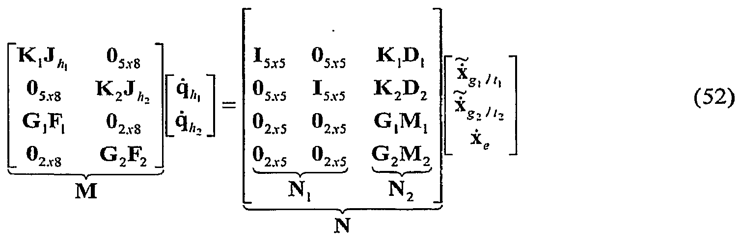
- the eye can be modeled as a constrained organ allowing only rotational motions about its center. This can be used to produce a simplify model of the twist of the organ as a three dimensional vector as indicated in equation 47.
- the overall Jacobian equation for the whole system with the eye simplifies to equation 52.
- At least four modes of operation can be performed by a robotic system for surgery: intra-organ manipulation and stabilization of the organ; organ manipulation with constrained intra-organ motions (e.g., manipulation of the eye while • maintaining the relative position of devices in the eye with respect to a target point inside the eye); organ manipulation with unconstrained intra-organ motion (e.g., eye manipulation regardless of the relative motions between devices in the eye and the eye); and simultaneous organ manipulation and intra-organ operation.
- organ manipulation with constrained intra-organ motions e.g., manipulation of the eye while • maintaining the relative position of devices in the eye with respect to a target point inside the eye
- organ manipulation with unconstrained intra-organ motion e.g., eye manipulation regardless of the relative motions between devices in the eye and the eye
- simultaneous organ manipulation and intra-organ operation e.g., simultaneous organ manipulation and intra-organ operation.
- each of the aforementioned four modes can be used to provide a dexterity evaluation.
- intra-organ operation with organ stabilization can be used to examine the intraocular dexterity, a measure of how well this system can perform a specified surgical task inside the eye with one of its two arms.
- organ manipulation with constrained intra-organ motions can be used to evaluate orbital dexterity, a measure of how well the two arms can grossly manipulate the rotational position of eye, while respecting the kinematic constraints at the incision points and maintaining zero velocity of the grippers with respect to the retina.
- organ manipulation with unconstrained intra-organ motion can be used to evaluate the orbital dexterity without constraints of zero velocity of the grippers with respect to the retina.
- simultaneous organ manipulation and intra-organ operation can be used to measure of intra-ocular and orbital dexterity while simultaneously rotating the eye and executing an intra-ocular surgical task.
- Equation 54 represents the mathematical model of intra-ocular manipulation while constraining the eye.
- equation 55 represents the mathematical model of orbital manipulation.
- the robotic arms can use standard ophthalmic instruments with no distal dexterity (e.g., a straight cannula capable of rotating about its own longitudinal axis). This yields a seven degree of freedom robotic arm.
- the Jacobian matrix e.g., a straight cannula capable of rotating about its own longitudinal axis.
- the method of using multiple characteristic lengths to normalize the overall Jacobian can be used for the purpose of performance evaluation.
- evaluating translational and rotational dexterity separately can be accomplished by investigating the upper and lower three rows of J 7( and J, (/ .
- Equation 56 and equation 58 can give the normalized sub-Jacobians for translational motions of seven degree of freedom and eight degree of freedom robots
- equation 57 and equation 59 can give the normalized sub-Jacobians for rotational motions of seven degree of freedom and eight degree of freedom robots.
- Organ manipulation with constrained intra-organ motions can be used to evaluated the orbital dexterity when simultaneously using both arms to rotate the eyeball.
- the evaluation can be designed to address the medical professionals' need to rotate the eye under the microscope in order to obtain a view of peripheral areas of the retina.
- the two arms can be predetermined to approach a target point on the retina.
- the relative position and orientation of the robot end effector with respect to a target point remains constant.
- the target point on the retina can be selected to be [5 ⁇ / 6, ⁇ ] ', defined in the eye and attached coordinate system ⁇ is ⁇ .
- Frame ⁇ E ⁇ can be defined similarly as the organ coordinate system ⁇ 0 ⁇ and can represent the relative rotation of the eye with respect to ⁇ w ⁇ .
- a desired rotation velocity of the eye of 10°/sec about the y-axis can be specified and the input joint actuation velocities can be calculated through the inverse of the Jacobian matrix.
- two serial robots e.g., intra-ocular dexterity robots
- the eyeball form a rigid body allowing no relative motion in between.
- the rates of the serial robot joints can be expected to be zero.
- both arms coordinate to manipulate the eyeball. Further, one arm also operates inside the eye along a specified path.
- the 5x1 Euler angle parameterization of the desired i ⁇ end effector velocity, x g /f can be related to the general twist of the i th robot end effector, x g( //j by the degenerate matrix K,- .
- the matrix can be derived using a relationship relating the Cartesian angular velocities to the Euler angle velocities:
- the 5x1 Euler parameterization used in the aforementioned path planning equation can be derived by applying a 5x6 degenerate matrix to the 6x1 Euler angle twist, as follows:
- each insertion arm moves at the insertion point only with the velocity equal to the velocity of the organ surface at that point plus any velocity along the insertion needle can be derived as follows.
- point m can be defined at the insertion point on the surface of the organ and
- m] can be defined as point on the insertion needle instantaneously coincident with m, .
- velocity of m ⁇ must be equal to the velocity of point m y in the plane perpendicular to the
- An expression for the velocity of the insertion point m can be related to the desired organ velocity, yielding: where .
- P 1 . [1 3x3 , M,. ] .
Abstract
Description


Claims
Priority Applications (6)
| Application Number | Priority Date | Filing Date | Title |
|---|---|---|---|
| CA002663797A CA2663797A1 (en) | 2006-09-19 | 2007-09-19 | Systems, devices, and methods for surgery on a hollow anatomically suspended organ |
| US12/441,566 US20100010504A1 (en) | 2006-09-19 | 2007-09-19 | Systems, devices, and methods for surgery on a hollow anatomically suspended organ |
| CN2007800346703A CN101998841B (en) | 2006-09-19 | 2007-09-19 | Systems, devices, and methods for surgery on a hollow anatomically suspended organ |
| AU2007297702A AU2007297702B2 (en) | 2006-09-19 | 2007-09-19 | Systems, devices, and methods for surgery on a hollow anatomically suspended organ |
| JP2009529220A JP2010504151A (en) | 2006-09-19 | 2007-09-19 | System, apparatus and method for surgery on hollow anatomically suspended organs |
| EP07838485A EP2063777A2 (en) | 2006-09-19 | 2007-09-19 | Systems, devices, and methods for surgery on a hollow anatomically suspended organ |
Applications Claiming Priority (4)
| Application Number | Priority Date | Filing Date | Title |
|---|---|---|---|
| US84568806P | 2006-09-19 | 2006-09-19 | |
| US60/845,688 | 2006-09-19 | ||
| US92084807P | 2007-03-30 | 2007-03-30 | |
| US60/920,848 | 2007-03-30 |
Publications (1)
| Publication Number | Publication Date |
|---|---|
| WO2008036304A2 true WO2008036304A2 (en) | 2008-03-27 |
Family
ID=39201070
Family Applications (1)
| Application Number | Title | Priority Date | Filing Date |
|---|---|---|---|
| PCT/US2007/020281 WO2008036304A2 (en) | 2006-09-19 | 2007-09-19 | Systems, devices, and methods for surgery on a hollow anatomically suspended organ |
Country Status (8)
| Country | Link |
|---|---|
| US (1) | US20100010504A1 (en) |
| EP (1) | EP2063777A2 (en) |
| JP (1) | JP2010504151A (en) |
| KR (1) | KR20090057984A (en) |
| CN (1) | CN101998841B (en) |
| AU (1) | AU2007297702B2 (en) |
| CA (1) | CA2663797A1 (en) |
| WO (1) | WO2008036304A2 (en) |
Cited By (15)
| Publication number | Priority date | Publication date | Assignee | Title |
|---|---|---|---|---|
| JP2010094768A (en) * | 2008-10-15 | 2010-04-30 | Ihi Corp | Manipulator system |
| NL1037348C2 (en) * | 2009-10-02 | 2011-04-05 | Univ Eindhoven Tech | Surgical robot, instrument manipulator, combination of an operating table and a surgical robot, and master-slave operating system. |
| US9333650B2 (en) | 2012-05-11 | 2016-05-10 | Vanderbilt University | Method and system for contact detection and contact localization along continuum robots |
| US9539726B2 (en) | 2012-04-20 | 2017-01-10 | Vanderbilt University | Systems and methods for safe compliant insertion and hybrid force/motion telemanipulation of continuum robots |
| US9549720B2 (en) | 2012-04-20 | 2017-01-24 | Vanderbilt University | Robotic device for establishing access channel |
| US9655681B2 (en) | 2010-10-01 | 2017-05-23 | Technische Universiteit Eindhoven | Surgical robot, instrument manipulator, combination of an operating table and a surgical robot, and master-slave operating system |
| US9687303B2 (en) | 2012-04-20 | 2017-06-27 | Vanderbilt University | Dexterous wrists for surgical intervention |
| US9956042B2 (en) | 2012-01-13 | 2018-05-01 | Vanderbilt University | Systems and methods for robot-assisted transurethral exploration and intervention |
| RU2692148C1 (en) * | 2018-06-22 | 2019-06-21 | Юрий Иванович Колягин | Device for diagnosing postural disorders |
| US10406026B2 (en) | 2008-05-16 | 2019-09-10 | The Johns Hopkins University | System and method for macro-micro distal dexterity enhancement in micro-surgery of the eye |
| US10967504B2 (en) | 2017-09-13 | 2021-04-06 | Vanderbilt University | Continuum robots with multi-scale motion through equilibrium modulation |
| US20210298954A1 (en) * | 2013-01-18 | 2021-09-30 | Auris Health, Inc. | Coordinated control of a water jet flow and an aspiration flow |
| US11737776B2 (en) | 2012-02-29 | 2023-08-29 | Procept Biorobotics Corporation | Automated image-guided tissue resection and treatment |
| US11759258B2 (en) | 2008-03-06 | 2023-09-19 | Aquabeam, Llc | Controlled ablation with laser energy |
| US11793394B2 (en) | 2016-12-02 | 2023-10-24 | Vanderbilt University | Steerable endoscope with continuum manipulator |
Families Citing this family (61)
| Publication number | Priority date | Publication date | Assignee | Title |
|---|---|---|---|---|
| US9232959B2 (en) | 2007-01-02 | 2016-01-12 | Aquabeam, Llc | Multi fluid tissue resection methods and devices |
| WO2008097540A2 (en) | 2007-02-02 | 2008-08-14 | Hansen Medical, Inc. | Robotic surgical instrument and methods using bragg fiber sensors |
| US8909319B2 (en) * | 2008-04-14 | 2014-12-09 | Mri Robotics Llc | Device and method for MRI-guided breast interventions |
| ES2762203T3 (en) * | 2009-03-27 | 2020-05-22 | New View Surgical Inc | Cannula with lighting and integrated camera |
| US8834358B2 (en) | 2009-03-27 | 2014-09-16 | EndoSphere Surgical, Inc. | Cannula with integrated camera and illumination |
| US9149929B2 (en) * | 2010-05-26 | 2015-10-06 | The Boeing Company | Methods and systems for inspection sensor placement |
| WO2012100211A2 (en) | 2011-01-20 | 2012-07-26 | Hansen Medical, Inc. | System and method for endoluminal and transluminal therapy |
| GB201115586D0 (en) * | 2011-09-09 | 2011-10-26 | Univ Bristol | A system for anatomical reduction of bone fractures |
| JP5856306B2 (en) | 2011-10-05 | 2016-02-09 | アナログ・デバイシズ・インコーポレーテッド | Two-wire communication system for high-speed data and power distribution |
| US10649948B2 (en) * | 2011-10-05 | 2020-05-12 | Analog Devices, Inc. | Two-wire communication systems and applications |
| WO2013067535A1 (en) * | 2011-11-04 | 2013-05-10 | The Johns Hopkins University | Steady hand micromanipulation robot |
| US9772665B2 (en) | 2012-10-05 | 2017-09-26 | Analog Devices, Inc. | Power switching in a two-wire conductor system |
| US9946680B2 (en) | 2012-10-05 | 2018-04-17 | Analog Devices, Inc. | Peripheral device diagnostics and control over a two-wire communication bus |
| US10744035B2 (en) * | 2013-06-11 | 2020-08-18 | Auris Health, Inc. | Methods for robotic assisted cataract surgery |
| US10426661B2 (en) | 2013-08-13 | 2019-10-01 | Auris Health, Inc. | Method and apparatus for laser assisted cataract surgery |
| US10219936B2 (en) * | 2014-09-11 | 2019-03-05 | Orbit Biomedical Limited | Therapeutic agent delivery device with advanceable cannula and needle |
| US10064752B2 (en) | 2014-09-11 | 2018-09-04 | Orbit Biomedical Limited | Motorized suprachoroidal injection of therapeutic agent |
| US20160287279A1 (en) | 2015-04-01 | 2016-10-06 | Auris Surgical Robotics, Inc. | Microsurgical tool for robotic applications |
| US9949749B2 (en) | 2015-10-30 | 2018-04-24 | Auris Surgical Robotics, Inc. | Object capture with a basket |
| US10231793B2 (en) | 2015-10-30 | 2019-03-19 | Auris Health, Inc. | Object removal through a percutaneous suction tube |
| US9955986B2 (en) | 2015-10-30 | 2018-05-01 | Auris Surgical Robotics, Inc. | Basket apparatus |
| US10478553B2 (en) * | 2016-03-09 | 2019-11-19 | Orbit Biomedical Limited | Apparatus for subretinal administration of therapeutic agent via a curved needle |
| JP6632487B2 (en) * | 2016-07-13 | 2020-01-22 | キヤノン株式会社 | Continuum robot, method of correcting kinematics, and control method of continuum robot |
| KR102545869B1 (en) | 2017-03-28 | 2023-06-23 | 아우리스 헬스, 인코포레이티드 | shaft operating handle |
| US10285574B2 (en) | 2017-04-07 | 2019-05-14 | Auris Health, Inc. | Superelastic medical instrument |
| CN110602976B (en) | 2017-04-07 | 2022-11-15 | 奥瑞斯健康公司 | Patient introducer alignment |
| CN107550569B (en) * | 2017-10-16 | 2023-08-04 | 鹰利视医疗科技有限公司 | Vertebra minimally invasive robot |
| US10751140B2 (en) | 2018-06-07 | 2020-08-25 | Auris Health, Inc. | Robotic medical systems with high force instruments |
| US11399905B2 (en) | 2018-06-28 | 2022-08-02 | Auris Health, Inc. | Medical systems incorporating pulley sharing |
| US10828118B2 (en) | 2018-08-15 | 2020-11-10 | Auris Health, Inc. | Medical instruments for tissue cauterization |
| EP3806758A4 (en) | 2018-08-17 | 2022-04-06 | Auris Health, Inc. | Bipolar medical instrument |
| CN112770689A (en) | 2018-09-26 | 2021-05-07 | 奥瑞斯健康公司 | Systems and apparatus for suction and irrigation |
| WO2020076447A1 (en) | 2018-10-08 | 2020-04-16 | Auris Health, Inc. | Systems and instruments for tissue sealing |
| WO2020131529A1 (en) | 2018-12-20 | 2020-06-25 | Auris Health, Inc. | Shielding for wristed instruments |
| US11589913B2 (en) | 2019-01-25 | 2023-02-28 | Auris Health, Inc. | Vessel sealer with heating and cooling capabilities |
| WO2020197625A1 (en) | 2019-03-25 | 2020-10-01 | Auris Health, Inc. | Systems and methods for medical stapling |
| KR102284387B1 (en) | 2019-06-21 | 2021-08-02 | 한국과학기술원 | Surgical system |
| US20220401168A1 (en) * | 2019-06-21 | 2022-12-22 | Korea Advanced Institute Of Science And Technology | Slave Device and Control Method Therefor, and Eye Surgery Device and Control Method Therefor |
| KR102277148B1 (en) * | 2019-06-21 | 2021-07-14 | 한국과학기술원 | Eye surgery apparatus and method for controlling the same |
| KR102284388B1 (en) | 2019-06-21 | 2021-08-02 | 한국과학기술원 | Slave device and method for controliing the same |
| WO2020263629A1 (en) | 2019-06-27 | 2020-12-30 | Auris Health, Inc. | Systems and methods for a medical clip applier |
| CN114040727A (en) | 2019-06-28 | 2022-02-11 | 奥瑞斯健康公司 | Medical instrument including a wrist with hybrid redirecting surfaces |
| US11439429B2 (en) | 2019-07-11 | 2022-09-13 | New View Surgical | Cannula assembly with deployable camera |
| US11896330B2 (en) | 2019-08-15 | 2024-02-13 | Auris Health, Inc. | Robotic medical system having multiple medical instruments |
| WO2021059099A1 (en) | 2019-09-26 | 2021-04-01 | Auris Health, Inc. | Systems and methods for collision detection and avoidance |
| WO2021064536A1 (en) | 2019-09-30 | 2021-04-08 | Auris Health, Inc. | Medical instrument with capstan |
| US11737835B2 (en) | 2019-10-29 | 2023-08-29 | Auris Health, Inc. | Braid-reinforced insulation sheath |
| US11582372B2 (en) | 2019-12-02 | 2023-02-14 | Adasky, Ltd. | System and method for lens alignment and bonding |
| US11025807B1 (en) | 2019-12-02 | 2021-06-01 | Adasky, Ltd. | System and method for optical alignment and calibration of an infrared camera lens |
| RU2721485C1 (en) * | 2019-12-12 | 2020-05-19 | Ассистирующие Хирургические Технологии (Аст), Лтд | Combined manipulator of robotosurgical complex |
| US11950872B2 (en) | 2019-12-31 | 2024-04-09 | Auris Health, Inc. | Dynamic pulley system |
| KR20220123269A (en) | 2019-12-31 | 2022-09-06 | 아우리스 헬스, 인코포레이티드 | Advanced basket drive mode |
| CN115802975A (en) | 2020-06-29 | 2023-03-14 | 奥瑞斯健康公司 | System and method for detecting contact between a connecting rod and an external object |
| EP4171428A1 (en) | 2020-06-30 | 2023-05-03 | Auris Health, Inc. | Robotic medical system with collision proximity indicators |
| US11357586B2 (en) | 2020-06-30 | 2022-06-14 | Auris Health, Inc. | Systems and methods for saturated robotic movement |
| CN111772919A (en) * | 2020-07-22 | 2020-10-16 | 宁夏回族自治区第五人民医院(宁夏回族自治区国家矿山医疗救护中心) | Drainage device for glaucoma valve filtering bulb part |
| CN112168482A (en) * | 2020-08-21 | 2021-01-05 | 西安交通大学 | Operation mechanism of ophthalmic cornea transplantation operation robot |
| US20240042593A1 (en) * | 2020-12-30 | 2024-02-08 | Noahtron Intelligence Medtech (Hangzhou) Co., Ltd. | Hybrid master-slave mapping method, robotic arm system, and computer device |
| CA3204500A1 (en) * | 2021-02-05 | 2022-08-11 | Steven T. Charles | Direct drive robot for vitreoretinal surgery |
| WO2023112732A1 (en) * | 2021-12-13 | 2023-06-22 | ソニーグループ株式会社 | Robot system and coordinate registration method |
| CN115533930A (en) * | 2022-09-08 | 2022-12-30 | 天津大学 | Novel large-scale unit assembly robot in aircraft cabin |
Family Cites Families (36)
| Publication number | Priority date | Publication date | Assignee | Title |
|---|---|---|---|---|
| US5737500A (en) * | 1992-03-11 | 1998-04-07 | California Institute Of Technology | Mobile dexterous siren degree of freedom robot arm with real-time control system |
| US5550953A (en) * | 1994-04-20 | 1996-08-27 | The United States Of America As Represented By The Administrator Of The National Aeronautics And Space Administration | On-line method and apparatus for coordinated mobility and manipulation of mobile robots |
| US7074179B2 (en) * | 1992-08-10 | 2006-07-11 | Intuitive Surgical Inc | Method and apparatus for performing minimally invasive cardiac procedures |
| US5410638A (en) * | 1993-05-03 | 1995-04-25 | Northwestern University | System for positioning a medical instrument within a biotic structure using a micromanipulator |
| JPH07328015A (en) * | 1994-06-14 | 1995-12-19 | Olympus Optical Co Ltd | Surgical manipulator system |
| US6120433A (en) * | 1994-09-01 | 2000-09-19 | Olympus Optical Co., Ltd. | Surgical manipulator system |
| US5588430A (en) * | 1995-02-14 | 1996-12-31 | University Of Florida Research Foundation, Inc. | Repeat fixation for frameless stereotactic procedure |
| US5784542A (en) * | 1995-09-07 | 1998-07-21 | California Institute Of Technology | Decoupled six degree-of-freedom teleoperated robot system |
| AU726713B2 (en) * | 1995-10-13 | 2000-11-16 | Transvascular, Inc. | Methods and apparatus for bypassing arterial obstructions and/or performing other transvascular procedures |
| US20020013573A1 (en) * | 1995-10-27 | 2002-01-31 | William B. Telfair | Apparatus and method for tracking and compensating for eye movements |
| AUPN929096A0 (en) * | 1996-04-17 | 1996-05-09 | Lions Eye Institute | A system for ocular ultramicrosurgery |
| US6254628B1 (en) * | 1996-12-09 | 2001-07-03 | Micro Therapeutics, Inc. | Intracranial stent |
| US6331181B1 (en) * | 1998-12-08 | 2001-12-18 | Intuitive Surgical, Inc. | Surgical robotic tools, data architecture, and use |
| US5943914A (en) * | 1997-03-27 | 1999-08-31 | Sandia Corporation | Master-slave micromanipulator apparatus |
| US7214230B2 (en) * | 1998-02-24 | 2007-05-08 | Hansen Medical, Inc. | Flexible instrument |
| US6233504B1 (en) * | 1998-04-16 | 2001-05-15 | California Institute Of Technology | Tool actuation and force feedback on robot-assisted microsurgery system |
| FR2779339B1 (en) * | 1998-06-09 | 2000-10-13 | Integrated Surgical Systems Sa | MATCHING METHOD AND APPARATUS FOR ROBOTIC SURGERY, AND MATCHING DEVICE COMPRISING APPLICATION |
| US6459926B1 (en) * | 1998-11-20 | 2002-10-01 | Intuitive Surgical, Inc. | Repositioning and reorientation of master/slave relationship in minimally invasive telesurgery |
| WO2000030557A1 (en) * | 1998-11-23 | 2000-06-02 | Microdexterity Systems, Inc. | Surgical manipulator |
| US6363938B2 (en) * | 1998-12-22 | 2002-04-02 | Angiotrax, Inc. | Methods and apparatus for perfusing tissue and/or stimulating revascularization and tissue growth |
| US6788018B1 (en) * | 1999-08-03 | 2004-09-07 | Intuitive Surgical, Inc. | Ceiling and floor mounted surgical robot set-up arms |
| JP4145464B2 (en) * | 2000-05-10 | 2008-09-03 | 独立行政法人科学技術振興機構 | Remote microsurgery system and slave manipulator insertion method. |
| US6519860B1 (en) * | 2000-10-19 | 2003-02-18 | Sandia Corporation | Position feedback control system |
| US7198630B2 (en) * | 2002-12-17 | 2007-04-03 | Kenneth I. Lipow | Method and apparatus for controlling a surgical robot to mimic, harmonize and enhance the natural neurophysiological behavior of a surgeon |
| US7077842B1 (en) * | 2001-08-03 | 2006-07-18 | Cosman Jr Eric R | Over-the-wire high frequency electrode |
| US8491549B2 (en) * | 2001-11-21 | 2013-07-23 | Iscience Interventional Corporation | Ophthalmic microsurgical system |
| US6989024B2 (en) * | 2002-02-28 | 2006-01-24 | Counter Clockwise, Inc. | Guidewire loaded stent for delivery through a catheter |
| DE10258702A1 (en) * | 2002-06-21 | 2004-01-08 | Curative Medical Devices Gmbh | Catheter arrangement has distal and proximal catheters with lumen, bendable distal point, side slit and guide wire |
| WO2004012803A1 (en) * | 2002-08-05 | 2004-02-12 | Resmed Limited | Inextensible headgear and cpap or ventilator mask assembly with same |
| US7766904B2 (en) * | 2003-01-31 | 2010-08-03 | Iridex Corporation | Adjustable laser probe for use in vitreoretinal surgery |
| CN1190171C (en) * | 2003-05-28 | 2005-02-23 | 天津大学 | Mechanical arm used in microsurgery operation robot |
| US7850642B2 (en) * | 2004-03-05 | 2010-12-14 | Hansen Medical, Inc. | Methods using a robotic catheter system |
| JP2006055273A (en) * | 2004-08-18 | 2006-03-02 | Olympus Corp | Surgery support system |
| CN1299650C (en) * | 2005-03-11 | 2007-02-14 | 天津大学 | Micro surgery operation robot control system with force sense |
| US9266239B2 (en) * | 2005-12-27 | 2016-02-23 | Intuitive Surgical Operations, Inc. | Constraint based control in a minimally invasive surgical apparatus |
| EP2037794B1 (en) * | 2006-06-13 | 2021-10-27 | Intuitive Surgical Operations, Inc. | Minimally invasive surgical system |
-
2007
- 2007-09-19 JP JP2009529220A patent/JP2010504151A/en active Pending
- 2007-09-19 US US12/441,566 patent/US20100010504A1/en not_active Abandoned
- 2007-09-19 CN CN2007800346703A patent/CN101998841B/en not_active Expired - Fee Related
- 2007-09-19 EP EP07838485A patent/EP2063777A2/en not_active Withdrawn
- 2007-09-19 KR KR1020097005552A patent/KR20090057984A/en not_active Application Discontinuation
- 2007-09-19 CA CA002663797A patent/CA2663797A1/en not_active Abandoned
- 2007-09-19 WO PCT/US2007/020281 patent/WO2008036304A2/en active Application Filing
- 2007-09-19 AU AU2007297702A patent/AU2007297702B2/en not_active Ceased
Cited By (19)
| Publication number | Priority date | Publication date | Assignee | Title |
|---|---|---|---|---|
| US11759258B2 (en) | 2008-03-06 | 2023-09-19 | Aquabeam, Llc | Controlled ablation with laser energy |
| US10406026B2 (en) | 2008-05-16 | 2019-09-10 | The Johns Hopkins University | System and method for macro-micro distal dexterity enhancement in micro-surgery of the eye |
| JP2010094768A (en) * | 2008-10-15 | 2010-04-30 | Ihi Corp | Manipulator system |
| NL1037348C2 (en) * | 2009-10-02 | 2011-04-05 | Univ Eindhoven Tech | Surgical robot, instrument manipulator, combination of an operating table and a surgical robot, and master-slave operating system. |
| WO2011040813A1 (en) | 2009-10-02 | 2011-04-07 | Technische Universiteit Eindhoven | Surgical robot, instrument manipulator, combination of an operating table and a surgical robot, and master-slave operating system |
| US9060795B2 (en) | 2009-10-02 | 2015-06-23 | Technische Universiteit Eindhoven | Surgical robot, instrument manipulator, combination of an operating table and a surgical robot, and master-slave operating system |
| US9655681B2 (en) | 2010-10-01 | 2017-05-23 | Technische Universiteit Eindhoven | Surgical robot, instrument manipulator, combination of an operating table and a surgical robot, and master-slave operating system |
| US9956042B2 (en) | 2012-01-13 | 2018-05-01 | Vanderbilt University | Systems and methods for robot-assisted transurethral exploration and intervention |
| US11737776B2 (en) | 2012-02-29 | 2023-08-29 | Procept Biorobotics Corporation | Automated image-guided tissue resection and treatment |
| US10500002B2 (en) | 2012-04-20 | 2019-12-10 | Vanderbilt University | Dexterous wrists |
| US9687303B2 (en) | 2012-04-20 | 2017-06-27 | Vanderbilt University | Dexterous wrists for surgical intervention |
| US9549720B2 (en) | 2012-04-20 | 2017-01-24 | Vanderbilt University | Robotic device for establishing access channel |
| US9539726B2 (en) | 2012-04-20 | 2017-01-10 | Vanderbilt University | Systems and methods for safe compliant insertion and hybrid force/motion telemanipulation of continuum robots |
| US9333650B2 (en) | 2012-05-11 | 2016-05-10 | Vanderbilt University | Method and system for contact detection and contact localization along continuum robots |
| US20210298954A1 (en) * | 2013-01-18 | 2021-09-30 | Auris Health, Inc. | Coordinated control of a water jet flow and an aspiration flow |
| US11793394B2 (en) | 2016-12-02 | 2023-10-24 | Vanderbilt University | Steerable endoscope with continuum manipulator |
| US10967504B2 (en) | 2017-09-13 | 2021-04-06 | Vanderbilt University | Continuum robots with multi-scale motion through equilibrium modulation |
| US11897129B2 (en) | 2017-09-13 | 2024-02-13 | Vanderbilt University | Continuum robots with multi-scale motion through equilibrium modulation |
| RU2692148C1 (en) * | 2018-06-22 | 2019-06-21 | Юрий Иванович Колягин | Device for diagnosing postural disorders |
Also Published As
| Publication number | Publication date |
|---|---|
| CN101998841B (en) | 2013-04-10 |
| EP2063777A2 (en) | 2009-06-03 |
| US20100010504A1 (en) | 2010-01-14 |
| CN101998841A (en) | 2011-03-30 |
| CA2663797A1 (en) | 2008-03-27 |
| JP2010504151A (en) | 2010-02-12 |
| KR20090057984A (en) | 2009-06-08 |
| AU2007297702B2 (en) | 2013-04-04 |
| AU2007297702A1 (en) | 2008-03-27 |
Similar Documents
| Publication | Publication Date | Title |
|---|---|---|
| AU2007297702B2 (en) | Systems, devices, and methods for surgery on a hollow anatomically suspended organ | |
| US20100331858A1 (en) | Systems, devices, and methods for robot-assisted micro-surgical stenting | |
| JP7434246B2 (en) | System and method for positioning a manipulator arm by clutching in zero orthogonal space simultaneously with zero space movement | |
| JP7022709B2 (en) | Computer-aided medical system and method | |
| CN108143497B (en) | System and method for tracking a path using null space | |
| KR102214811B1 (en) | Systems and methods for using the null space to emphasize manipulator joint motion anisotropically | |
| Wei et al. | Design and theoretical evaluation of micro-surgical manipulators for orbital manipulation and intraocular dexterity | |
| US9492235B2 (en) | Manipulator arm-to-patient collision avoidance using a null-space | |
| CN105050526B (en) | Using kernel with the system and method at the convenient edge into cartesian coordinate space | |
| CN104334109B (en) | For the system and method for reconfiguring of the order of the surgical manipulator using kernel | |
| Munoz et al. | A medical robotic assistant for minimally invasive surgery | |
| CN109171975B (en) | System and method for managing multiple null-space targets and saturated SLI behavior | |
| KR20190007505A (en) | Computer Assisted Remote Operation Surgical System and Method | |
| CN109715104A (en) | Area of computer aided remotely operates surgery systems and method | |
| Lin et al. | Biometry-based concentric tubes robot for vitreoretinal surgery | |
| Wei et al. | Performance evaluation for multi-arm manipulation of hollow suspended organs | |
| Song et al. | Intraocular snake integrated with the steady-hand eye robot for assisted retinal microsurgery | |
| Mitros et al. | Optic nerve sheath fenestration with a multi-arm continuum robot | |
| Wu et al. | An optimized tilt mechanism for a new steady-hand eye robot | |
| Zhao et al. | Human-robot interaction in retinal surgery: A comparative study of serial and parallel cooperative robots | |
| Dai et al. | Eye Robotic System for Vitreoretinal Surgery | |
| Wei | Design and implementation of high-precision hybrid robotic systems with application for ophthalmic micro-surgery |
Legal Events
| Date | Code | Title | Description |
|---|---|---|---|
| WWE | Wipo information: entry into national phase |
Ref document number: 200780034670.3 Country of ref document: CN |
|
| 121 | Ep: the epo has been informed by wipo that ep was designated in this application |
Ref document number: 07838485 Country of ref document: EP Kind code of ref document: A2 |
|
| WWE | Wipo information: entry into national phase |
Ref document number: 2007297702 Country of ref document: AU |
|
| REEP | Request for entry into the european phase |
Ref document number: 2007838485 Country of ref document: EP |
|
| WWE | Wipo information: entry into national phase |
Ref document number: 2007838485 Country of ref document: EP |
|
| WWE | Wipo information: entry into national phase |
Ref document number: 1283/DELNP/2009 Country of ref document: IN |
|
| ENP | Entry into the national phase |
Ref document number: 2007297702 Country of ref document: AU Date of ref document: 20070919 Kind code of ref document: A |
|
| ENP | Entry into the national phase |
Ref document number: 2663797 Country of ref document: CA |
|
| WWE | Wipo information: entry into national phase |
Ref document number: 1020097005552 Country of ref document: KR |
|
| ENP | Entry into the national phase |
Ref document number: 2009529220 Country of ref document: JP Kind code of ref document: A |
|
| NENP | Non-entry into the national phase |
Ref country code: DE |
|
| WWE | Wipo information: entry into national phase |
Ref document number: 12441566 Country of ref document: US |