US9831724B2 - Access control system using a wearable access sensory implementing an energy harvesting technique - Google Patents

Access control system using a wearable access sensory implementing an energy harvesting technique Download PDF

Info

Publication number
US9831724B2
US9831724B2 US14/956,803 US201514956803A US9831724B2 US 9831724 B2 US9831724 B2 US 9831724B2 US 201514956803 A US201514956803 A US 201514956803A US 9831724 B2 US9831724 B2 US 9831724B2
Authority
US
United States
Prior art keywords
storage device
voltage level
energy storage
energy
person
Prior art date
Legal status (The legal status is an assumption and is not a legal conclusion. Google has not performed a legal analysis and makes no representation as to the accuracy of the status listed.)
Active, expires
Application number
US14/956,803
Other versions
US20160156219A1 (en
Inventor
Richard L. Copeland
Melwyn F. Sequeira
Current Assignee (The listed assignees may be inaccurate. Google has not performed a legal analysis and makes no representation or warranty as to the accuracy of the list.)
Sensormatic Electronics LLC
Original Assignee
Tyco Fire and Security GmbH
Priority date (The priority date is an assumption and is not a legal conclusion. Google has not performed a legal analysis and makes no representation as to the accuracy of the date listed.)
Filing date
Publication date
Application filed by Tyco Fire and Security GmbH filed Critical Tyco Fire and Security GmbH
Priority to US14/956,803 priority Critical patent/US9831724B2/en
Assigned to TYCO FIRE & SECURITY GMBH reassignment TYCO FIRE & SECURITY GMBH ASSIGNMENT OF ASSIGNORS INTEREST (SEE DOCUMENT FOR DETAILS). Assignors: COPELAND, RICHARD L., SEQUEIRA, MELWYN F.
Publication of US20160156219A1 publication Critical patent/US20160156219A1/en
Application granted granted Critical
Publication of US9831724B2 publication Critical patent/US9831724B2/en
Assigned to Sensormatic Electronics, LLC reassignment Sensormatic Electronics, LLC ASSIGNMENT OF ASSIGNORS INTEREST (SEE DOCUMENT FOR DETAILS). Assignors: TYCO FIRE & SECURITY GMBH
Active legal-status Critical Current
Adjusted expiration legal-status Critical

Links

Images

Classifications

    • HELECTRICITY
    • H02GENERATION; CONVERSION OR DISTRIBUTION OF ELECTRIC POWER
    • H02JCIRCUIT ARRANGEMENTS OR SYSTEMS FOR SUPPLYING OR DISTRIBUTING ELECTRIC POWER; SYSTEMS FOR STORING ELECTRIC ENERGY
    • H02J50/00Circuit arrangements or systems for wireless supply or distribution of electric power
    • H02J50/20Circuit arrangements or systems for wireless supply or distribution of electric power using microwaves or radio frequency waves
    • G07C9/00007
    • GPHYSICS
    • G07CHECKING-DEVICES
    • G07CTIME OR ATTENDANCE REGISTERS; REGISTERING OR INDICATING THE WORKING OF MACHINES; GENERATING RANDOM NUMBERS; VOTING OR LOTTERY APPARATUS; ARRANGEMENTS, SYSTEMS OR APPARATUS FOR CHECKING NOT PROVIDED FOR ELSEWHERE
    • G07C9/00Individual registration on entry or exit
    • G07C9/20Individual registration on entry or exit involving the use of a pass
    • HELECTRICITY
    • H02GENERATION; CONVERSION OR DISTRIBUTION OF ELECTRIC POWER
    • H02JCIRCUIT ARRANGEMENTS OR SYSTEMS FOR SUPPLYING OR DISTRIBUTING ELECTRIC POWER; SYSTEMS FOR STORING ELECTRIC ENERGY
    • H02J50/00Circuit arrangements or systems for wireless supply or distribution of electric power
    • H02J50/001Energy harvesting or scavenging

Definitions

  • This document relates generally to Access Control Systems (“ACSs”) for restricted areas. More particularly, this document relates to ACSs using a wearable access sensor implementing an energy harvesting technique.
  • ACSs Access Control Systems
  • ACSs There are many ACSs known in the art.
  • One such ACS comprises a plurality of Access Control Readers (“ACRs”) mounted at exits and/or entries of restricted areas.
  • ACR Access Control Readers
  • an ACR may be disposed adjacent to a doorway through which access to a restricted room is gained.
  • a badge worn by a person is used to gain access to a restricted room via the ACR.
  • the badge comprises a Low Frequency (“LF”) passive Radio Frequency Identifier (“RFID”) communication device disposed thereon or therein.
  • the LF passive RFID communication device typically operates at a frequency of 125 kHz.
  • the ACR is a near field device with a detection range of about 5 cm or less.
  • the ACS tracks which entries a given person passes through for purposes of entering a restricted area. However, the ACS does not track when the person leaves each visited restricted area within the given time period.
  • Another conventional ACS employs beacons and wireless communication devices (e.g., mobile phones) which communicate via Bluetooth technology.
  • a personal identifier is stored on the wireless communication device, and communicated to the beacon when the person is in proximity thereto. In response to the reception of the personal identifier, the ACS would allow the person to have access to the restricted area.
  • the present disclosure concerns systems and methods for operating a Wearable Access Sensor (“WAS”).
  • the methods comprise capturing RF energy by the WAS being worn by a person.
  • the RF energy is emitted within a surrounding environment from equipment disposed at an access point of a restricted area.
  • the RF energy is passed through a switch that is normally in a position which provides an electrical connection between an antenna of the WAS and a full wave rectifier of the WAS.
  • the WAS then performs operations to convert the RF energy into direct current for generating electric power.
  • the electric power is supplied to an energy storage device (e.g., a super capacitor) of the WAS for charging the energy storage device to a pre-determined voltage level.
  • Power is supplied from the energy storage device to a controller of the WAS when a voltage level of the energy storage device is equal to or greater than the pre-determined voltage level.
  • the methods also comprise: generating and sending a switch control signal from the controller to the switch to cause the switch to change positions such that the switch is disconnected from the antenna and connected to a transceiver of the WAS; and communicating information from the WAS to a wireless edge device.
  • the information comprises user credentials that are useful for authenticating a user such that the user can be granted or denied access to the restricted area.
  • the power is supplied from the energy storage device to the controller via a voltage converter.
  • the voltage converter changes the pre-determined voltage level to a sub-threshold voltage level. More particularly, the voltage converter increases or decreases a voltage level of a signal received from the energy storage device to a sub-threshold voltage level.
  • the sub-threshold voltage level is at least one order of magnitude below a normal operating range for the WAS.
  • the voltage level change is performed prior to supplying the power from the energy storage device to the controller.
  • the normal operating range of a voltage level may be within 1.2 Volts to 3.6 Volts.
  • the sub-threshold voltage level may be within 200 milli-Volts to 600 milli-Volts.
  • a directionality of the WAS's movement is determined based on at least one of a rate of change of a charging voltage of the energy storage device and a detected direction of travel of the WAS in relation to the access point.
  • FIG. 1 is a perspective view of an exemplary ACS.
  • FIG. 2 is a block diagram of an exemplary architecture for the WAS shown in FIG. 1 .
  • FIGS. 3A-3B collectively provide a flow diagram of an exemplary method for controlling access to a restricted area.
  • FIGS. 4A-4B collectively provide a flow diagram of another exemplary method for controlling access to a restricted area.
  • FIG. 5 provides a flow diagram of an exemplary method for operating a WAS.
  • FIG. 6 provides a graph showing charging of a capacitor.
  • the present invention may be implemented on one or any combination of hardware, firmware and software.
  • the present invention may also be implemented as instructions contained in or on a machine-readable medium, which may be read and executed by one or more processors to enable performance of the operations described herein.
  • a machine-readable medium may include any mechanism for storing, transmitting and/or receiving information in a form readable by a machine (e.g., a computer).
  • a machine-readable medium may include a tangible storage medium, such as but not limited to, Read Only Memory (“ROM”), Random Access Memory (“RAM”) and/or a flash memory device.
  • ROM Read Only Memory
  • RAM Random Access Memory
  • a machine-readable medium may also include a propagated signal which has been modulated to encode the instructions, such as but not limited to electromagnetic, optical or acoustical carrier wave signals.
  • wireless and its derivatives may be used to describe circuits, devices, systems, methods, techniques, communications channels, etc., that communicate data by using modulated electromagnetic radiation through a non-solid medium. The term does not imply that the associated devices do not contain any wires, although in some scenarios they might not.
  • the present disclosure provides a novel ACS implementing a method for controlling access to restricted areas.
  • An exemplary architecture 100 for the novel ACS is provided in FIG. 1 .
  • An object of ACS 100 is to use a wearable device that can harvest just enough Radio Frequency (“RF”) energy emanating from a wireless edge device (e.g., a device mounted at an entryway), supply the harvested power to an on-board wireless transceiver and controller so as to enable wireless authentication and access through an entry way.
  • RF Radio Frequency
  • ACS 100 is generally configured to manage the entrance and exit of people through at least one secure area 118 .
  • each secure area is entered and exited via an access point, such as a doorway 102 .
  • Exit and entrance antennas 106 , 108 are disposed on front and back surfaces of the same structural wall or different structural walls located adjacent to the access point 102 .
  • the entrance antenna 108 is disposed on a front sidewall surface 130 of a structural wall 132 located adjacent to the doorway 102 .
  • the exit antenna 106 is disposed on a back sidewall surface (not shown in FIG. 1 ) of a structural wall 134 located adjacent to the doorway 102 .
  • the antennas 106 , 108 are also communicatively coupled to a reader 104 .
  • the reader 104 is communicatively coupled to a Data Processing System (“DPS”) 112 via a network (e.g., an Intranet and/or an Internet).
  • DPS Data Processing System
  • a WAS 114 is assigned to each individual authorized for accessing restricted areas of a business entity.
  • the WAS 114 comprises a wearable communications device that can be worn by the person 116 to which it is assigned.
  • WAS 114 comprises a wrist band with internal sensor circuitry (not shown in FIG. 1 ).
  • the present invention is not limited in this regard.
  • WAS 114 can include any other type of wearable item, such as a watch, necklace, hat, headset or clip-on item which can be worn on a person or on a person's clothing at a location offset from the person's center axis. In all scenarios, the WAS 114 facilitates the entrance and exit of the authorized person through the secure area 118 .
  • FIG. 2 A schematic illustration of an exemplary architecture for the WAS 114 is provided FIG. 2 , which will be described below.
  • the WAS 114 runs at a sub-threshold power or voltage level.
  • the term “sub-threshold”, as used herein, means that a power level and/or voltage level falls at least one order of magnitude below a normal operating range for a given device.
  • traditional processing systems normally operate at a power level of approximately 3 milli-Watts and/or a voltage level within 1.2 Volts to 3.6 Volts.
  • the WAS 114 runs at a sub-threshold power level at approximately 3 micro-Watts and/or a voltage level within 200 milli-Volts to 600 milli-Volts.
  • the WAS 114 may include a diode junction (or rectifier) to rectify an incoming signal and a transistor to switch the incoming signal to/from a transceiver.
  • the input voltage needed to operate the diode junction and transistor is of a threshold voltage level (e.g., 1.5-3.0 Volts, 0.7 Volts for the diode junction and 0.6 Volts for the transistor).
  • the input voltage needed to operate the diode junction and transistor of the WAS 114 is of a sub-threshold voltage level (e.g., 0.6 Volts) which is lower than the threshold voltage level (e.g., 1.5-3.0 Volts) of conventional RFID devices.
  • the diode bridge employed by the present solution comprise low drop out diodes which enable active rectification at less than 20 milli-Volts compared to conventional diodes which enable rectification at 300-700 milli-Volts.
  • the WAS 114 comprises an energy harvesting circuit 220 and a voltage converter 290 , as shown in FIG. 2 .
  • the energy harvesting circuit 220 is provided for deriving energy from an external source to power other electronic components 204 , 206 , 208 , 216 internal to the WAS 114 .
  • the energy harvesting circuit 220 is generally configured to collect received energy from RF fields.
  • the energy harvesting circuit 220 is sized and shaped to minimize the amount of space taken up thereby on the WAS 114 having a height ⁇ approximately 2 inches and a width ⁇ approximately 3 inches.
  • the energy harvesting circuit 220 can include, but is not limited to, a device having a part number BQ25570 which is available from Texas Instruments of Dallas, Tex. Additionally or alternatively, the energy harvesting circuit 220 can include, but is not limited to, that shown in FIG. 2 and discussed below.
  • the voltage converter 290 comprises an electric power converter which changes the output voltage of an electrical power source, such as the energy harvesting circuit 220 .
  • the voltage converter 290 includes, but is not limited to, an inverter, a semiconductor switch (e.g., a transistor), passive components (e.g., inductors, capacitors, resistors, and/or diodes), and/or a transformer to change the voltage of AC power.
  • the voltage converter 290 raises or lowers the level of an input voltage received from the energy harvesting circuit 220 to the sub-threshold voltage level (e.g., 0.6 Volts).
  • Reducing the required operating voltage of the WAS 114 means a lower field level (volts per meter) is required for a given antenna size.
  • running the WAS 114 at a sub-threshold power or voltage level means an Integrated Circuit (“IC”) 280 of the WAS 114 operates more slowly than normal super-threshold ICs, but runs at 100-1000 times lower current.
  • IC Integrated Circuit
  • the IC 280 of the WAS 114 can implement components 212 , 220 and 290 .
  • the IC 280 can be created by (1) changing the processing parameters for the mask set during fabrication, (2) changing the implantation rules for dopants and/or (3) changing processing parameters.
  • the IC can be made on regular CMOS fabrication lines without affecting the normal operating of the line. This allows most FAB lines to create sub-threshold electronics on their standard lines using the normal mask processes used in fabrication.
  • the advantages of running the IC 280 at a sub-threshold power or voltage level are substantial.
  • the IC 280 is ideally suited to working with energy harvesting devices which are notorious for supplying very low power and voltages.
  • the IC's 280 use with resulting inlays or RFID devices. Since the operating power of the IC 280 is substantially reduced, the read range for a given sized inlay is ten to fifteen times larger as compared to that of conventional RFID devices.
  • an inlay that is only one centimeter long can operate like a conventional inlay that is ten to fifteen centimeters long.
  • the size of the antenna 202 can be reduced as compared to that of conventional RFID devices, while still maintaining the larger read range.
  • the size reduction of the inlay and antenna provide significant advantages when placing the IC 280 in/on packaging or incorporating the IC 280 into a wearable item.
  • the energy harvesting circuit 220 comprises a switch 250 , a full wave rectifier 252 , an energy harvester power manager 258 and an energy storage device 262 .
  • the energy harvesting circuit 220 may also comprise matching circuits (not shown) to optimize a power transfer from an antenna 202 of the WAS 114 and/or to impedance match the antenna to a transceiver 204 of the WAS 114 .
  • Antenna 202 can include any known or to be known antenna.
  • the antenna comprises an antenna described in U.S. Patent Publication No. 2015/0054696. The present invention is not limited in this regard.
  • the energy storage device 262 comprises a super capacitor.
  • the switch 250 includes a Field Effect Transistor (“FET”) switch.
  • the FET switch may comprise a Heterostructure FET (“HFET”) which without applied power directly couples the antenna 202 to the energy harvesting electronics.
  • HFET Heterostructure FET
  • the energy harvesting circuit 220 charges up the energy storage device 262 (e.g., a super capacitor) to a pre-determined voltage level.
  • the switch 250 is normally in a position which provides an electrical connection or closed circuit between the antenna 202 and the full wave rectifier 252 , as shown in FIG. 2 . In the absence of an energy source (and hence the application of a voltage to power the switch), the switch 250 is in an indeterminate state causing the RF signal to bleed through both channels thereof, but with significantly reduced output. However, the voltage output is sufficient to turn on or enable the energy harvesting electronics 252 , 258 , 262 such that RF energy can be captured thereby.
  • the captured RF energy is passed through the switch 250 by virtue of the switches characteristics described above.
  • the energy harvester power manager 258 converts the received RF energy into direct current for generating electric power.
  • the electric power is supplied to the energy storage device 262 (e.g., a super capacitor) for charging the same to the pre-determined voltage level.
  • a graph is provided in FIG. 6 that is useful for understanding the charging of an energy storage device, such as a capacitor.
  • the voltage on the energy storage device 262 is sufficient to power up the components 204 , 206 of the Short Range Communication (“SRC”) device 212 as the user of the WAS 114 passes through the RF field generated by the wireless edge device located at the entryway.
  • SRC Short Range Communication
  • the controller 206 When the energy storage device 262 is charged to the pre-determined voltage level, power is supplied from the energy storage device 262 to the controller 206 via the energy harvester power manager 258 .
  • the controller 206 generates and sends a switch control signal 266 to the switch 250 .
  • the switch control signal 266 includes a command to cause the switch 250 to change positions.
  • the switch 250 is disconnected from the energy harvesting circuit 220 , whereby an open circuit is formed between the antenna 202 and the full wave rectifier 252 .
  • the switch 250 is connected to the transceiver 204 so as to allow communication of information from the WAS 114 to a nearby communications device.
  • the controller 206 initiates communications with the wireless edge device such that user credentials are passed from the WAS 114 to the wireless edge device.
  • the wireless edge device processes the user credentials for authenticating the user. If the user is not authenticated, then (s)he is denied access to the restricted area. In contrast, if the user is authenticated, then (s)he is granted access
  • the antenna 202 of WAS 114 may comprise a directional antenna arranged to point away from the person's body when the WAS 114 is being worn thereby.
  • the antenna 202 is coupled to the SRC device 212 implementing SRC technology.
  • the SRC technology includes, but is not limited to, RFID technology which uses radio-frequency electromagnetic fields to identify persons and/or objects when they come close to the reader 104 .
  • the SRC device 212 facilitates communication of a unique identifier 210 to the reader 104 via SRC reply signals in response to interrogation signals sent from reader 104 .
  • the unique identifier 210 is then used by the reader 104 and/or DPS 112 to automatically identify the person 116 which is in proximity to the access point 102 and/or whether the person is authorized to access the restricted area.
  • the reader 104 determines the directionality of the WAS 114 emitting the SRC reply signal. This determination is made based on RSSI measurements of the power present in the SRC reply signal received by an antenna 106 or 108 from the WAS 114 .
  • the RSSI measurements specify the signal strength of the SRC reply signal received at antenna 106 or antenna 108 , and whether the signal strength is increasing or decreasing during a given period of time. If the signal strength of the SRC reply signal is increasing during the given period of time, then the WAS 114 is deemed to be traveling towards to the respective antenna 106 or 108 . In contrast, if the signal strength of the SRC reply signal is decreasing during the given period of time, then the WAS 114 is deemed to be traveling away from the respective antenna 106 or 108 .
  • additional motion sensors 120 , 122 are employed herein.
  • the motion sensors may be provided at the access point 102 .
  • a first motion sensor 122 is disposed on the front sidewall surface 130 of the structural wall 132 located adjacent to the access point 102 .
  • a second motion sensor 122 is disposed on a back sidewall surface (not shown in FIG. 1 ) of the structural wall 134 located adjacent to the access point 102 .
  • the motion sensors 120 , 122 are used to determine the direction and/or speed/velocity of travel of the person 116 in proximity to the access point 102 .
  • Information specifying the person's direction and/or speed/velocity of travel is provided from the motion sensors 120 , 122 to the reader 104 .
  • the present invention is not limited to the motion sensor configuration shown in FIG. 1 .
  • the motion sensors provided in wireless communication devices e.g., mobile phones or smart phones
  • the reader 104 forwards the information received from the motion sensor(s) 120 , 122 to the DPS 112 via network 110 .
  • reader 104 communicates information to the DPS 112 indicating the directionality of the WAS 114 (i.e., whether the WAS 114 is traveling towards or away from the antenna 106 or 108 ).
  • the DPS 112 may be located in the same facility as the reader 104 or in a different facility remote from the facility in which the reader 104 is disposed.
  • the network 110 may comprise an Intranet and/or the Internet.
  • each exit and/or entrance to a restricted area in each facility of a business entity may have access control sensory systems 104 - 108 , 120 , 122 disposed thereat so as to define a distributed network of access control sensor systems.
  • the information is used to determine whether or not the person is attempting to enter or exit the access point 102 . For example, if the information indicates that the WAS 114 is traveling towards the entrance antenna 108 and the person is moving in direction 124 , then a determination is made that the person desires to enter the restricted area via access point 102 . In contrast, if the information indicates that the WAS 114 is traveling towards antenna 106 and the person is moving in direction 126 , then a determination is made that the person desires to exit the restricted area via the access point 102 . If the information indicates that the WAS 114 is traveling away from the antenna 108 , then a determination is made that the person is not trying to enter the restricted area. Similarly, if the information indicates that the WAS 114 is traveling away from the antenna 106 , then a determination is made that the person is not trying to exit the restricted area.
  • the DPS 112 may also analyze patterns of motion defined by the information to determine whether or not the person desires to enter or exit the access point 102 . For example, if the information indicates that the person 116 is traveling in a direction 124 , 136 or 138 towards the access point 102 during a first period of time and then travels in a direction 126 , 136 or 138 away from the access point 102 during an immediately following second period of time, then a determination is made that the person does not want to gain access to the restricted area, but is simply passing by the access point.
  • the information indicates that the person 116 is traveling at a first speed in a direction 124 , 136 or 138 towards the access point 102 during a first period of time and then slows down as (s)he approaches the access point, a determination is made that the person does want to gain access to the restricted area.
  • the information indicates that the person 116 is traveling at a first speed in a direction 124 , 136 or 138 towards the access point 102 during a first period of time and stops upon reaching the access point, a determination is made that the person does want to gain access to the restricted area.
  • the DPS 112 Upon determining that the person does not want to enter or exit the restricted area, the DPS 112 simply logs the unique identifier, the directionality information, the motion direction information, the speed/velocity information, and/or the results of the information analysis in a data store (not shown in FIG. 1 ) for later use. Upon determining that the person does want to enter the restricted area, the DPS 112 compares the unique identifier 210 to a plurality of unique identifiers stored in the data store to check whether the person is authorized to enter the restricted area. If the person is authorized to enter the restricted area, the DPS 112 causes a door opening actuator 128 to be actuated (e.g., for unlocking a lock).
  • the DPS 112 also logs results of the information analysis and/or information specifying that access to the restricted area was provided to the person at a particular time. Upon determining that the person wants to exit the restricted area, the DPS 112 causes a door opening actuator 128 to be actuated, and also logs results of the information analysis and/or information specifying that the person exited the restricted area at a particular time.
  • the data logging allows the DPS 112 to track the access points through which the person enters and exits, and the time of such entering and exiting.
  • This historical information is useful for a variety of reasons. For example, the historical information can be used to determine when employees arrive at and/or leave work, whereby the need for conventional employee time-attendance systems requiring each employee to manually clock-in upon arrival at work and clock-out upon leaving work is no longer necessary.
  • the historical information can also be used to identify individuals who gained access to a restricted area when a possible theft occurred or when equipment was removed from the restricted area.
  • the above described access control system overcomes certain drawbacks of conventional access control systems.
  • authorized individuals do not need to take any manual actions (e.g., swiping a card) to gain access to restricted areas.
  • the need for certain access control equipment e.g., card readers
  • the need for certain access control equipment has been eliminated, thereby reducing the overall cost of implementing the present access control system 100 .
  • the WAS 114 operates in both an energy harvesting mode and a communications mode.
  • the energy harvesting circuit 220 collects energy every time WAS 114 passes by an access point.
  • the collected energy is stored in the energy storage device 222 (e.g., a capacitor).
  • the mode of the WAS 114 is changed from the energy harvesting mode to the communications mode.
  • an SRC identifier signal is sent to the reader 104 via antenna 202 at the access point 102 .
  • the SRC identifier signal comprises the unique identifier 210 .
  • Information 214 indicating the rate of change of the charging voltage of the energy storage device 222 may also be sent from the WAS 114 to the reader 104 via the SRC identifier signal.
  • the rate of change information 214 specifies directionality of the WAS 114 .
  • the reader 104 communicates the unique identifier 210 and/or rate of change information 214 to the DPS 112 .
  • the motion sensors 120 , 122 are also employed along with the multi-mode WAS 114 (i.e., the WAS configured to operate in both an energy harvesting mode and a communications mode).
  • the motion sensors 120 , 122 are used to determine the direction and/or speed/velocity of travel of the person 116 in proximity to the access point 102 .
  • Information specifying the person's direction and/or speed/velocity of travel is provided from the motion sensors 120 , 122 to the reader 104 .
  • the reader 104 is simply an edge connect module that controls the door opening actuator.
  • an interrogation reader e.g., an RFID reader
  • step 302 begins with step 302 and continues with step 304 where an interrogation signal is transmitted from a reader (e.g., reader 104 of FIG. 1 ) of an ACS (e.g., ACS 100 of FIG. 1 ).
  • an SRC reply signal is transmitted from a WAS (e.g., WAS 114 of FIG. 1 ), as shown by step 306 .
  • the SRC reply signal comprises a unique identifier (e.g., unique identifier 210 of FIG. 2 ).
  • the SRC reply signal is received at an antenna (e.g., antenna 106 or 108 of FIG. 1 ) coupled to the reader.
  • RSSI measurement data specifying the power present in the SRC reply signal over a given period of time, as shown by step 310 .
  • the RSSI measurement data is used by the reader to determine if the signal strength of the SRC reply message is increasing. Notably, this determination can alternatively be performed by a DPS (e.g., DPS 112 of FIG. 1 ). In this case, method 300 can be amended accordingly. Such changes are understood by persons skilled in the art.
  • step 314 is performed where first information is generated indicating that the WAS is traveling away from the antenna.
  • step 316 is performed where second information is generated indicating that the WAS is traveling towards the antenna.
  • Step 318 involves detecting the direction and/or speed/velocity of motion of the person (e.g., person 116 of FIG. 1 ) wearing the WAS.
  • One or more motion sensors e.g., sensors 120 and/or 122 of FIG. 1
  • step 320 third information is communicated to the reader specifying the detected direction and/or speed/velocity of the person's motion.
  • the reader then communicates the following information to the DPS: the unique identifier; a time stamp; the first information; the second information; and/or the third information, as shown by step 322 .
  • operations are performed to determine whether or not the person is attempting to enter or exit the restricted area using the information received in previous step 322 . For example, if the received information indicates that the WAS is traveling towards an entrance antenna (e.g., antenna 108 of FIG. 1 ) and the person is moving in a first direction (e.g., direction 124 of FIG. 1 ), then a determination is made that the person desires to enter the restricted area via an access point (e.g., access point 102 of FIG. 1 ). In contrast, if the received information indicates that the WAS is traveling towards an exit antenna (e.g., antenna 106 of FIG. 1 ) and the person is moving in a direction opposite the first direction (e.g., direction 126 of FIG.
  • an entrance antenna e.g., antenna 108 of FIG. 1
  • an exit antenna e.g., antenna 106 of FIG. 1
  • the DPS additionally or alternatively analyzes patterns of motion defined by the received information to determine whether or not the person desires to enter or exit the access point.
  • step 324 method 300 continues with decision step 326 of FIG. 3B . If it is determined that the person does not want to enter or exit the restricted area [ 326 :NO], then step 328 is performed where the following information is logged in a data store: the unique identifier; a time stamp; the first or second information; the third information; and/or the fourth information indicating the results of the operations performed in previous step 324 . Subsequently, step 350 is performed where method 300 ends or other processing is performed.
  • step 332 is performed when the person is attempting to enter the restricted area, and therefore involves comparing the unique identifier with a plurality of unique identifiers stored in a data store to check whether the person is authorized to enter the restricted area.
  • the DPS performs various actions as shown by steps 334 - 340 .
  • Steps 334 - 340 involve: causing a request for identification and location information to be sent to a PCD (e.g., PCD 150 of FIG. 1 ) in the person's possession; performing operations by the PCD to obtain information useful for determining its current location within a surrounding environment; relaying the information obtained in step 336 to a remote device via a wireless communications link; and estimating the location of the PCD.
  • a PCD e.g., PCD 150 of FIG. 1
  • step 342 is performed where the DPS performs operation to cause actuation of a door opening actuator (e.g., door opening actuation 128 of FIG. 1 ).
  • steps 344 - 346 are performed to log the following information: the unique identifier; the time stamp; the first or second information; the third information; the fourth information; and/or fifth information indicating that the person entered or exited the restricted area at a particular time.
  • the logged information can optionally be used in step 348 to perform a historical analysis of the person's movement through a facility.
  • step 350 is performed where method 300 ends or other processing is performed.
  • method 400 begins with step 402 and continues with step 404 where an energy harvesting circuit (e.g., circuit 220 of FIG. 2 ) of a WAS (e.g., WAS 114 of FIG. 1 ) collects energy. The collected energy is then stored in an energy storage device (e.g., device 222 of FIG. 2 ) of the WAS as shown by step 406 .
  • an energy harvesting circuit e.g., circuit 220 of FIG. 2
  • WAS e.g., WAS 114 of FIG. 1
  • step 410 When the energy storage device charges to an operating voltage level of an SRC device (e.g., SRC device 212 of FIG. 2 ) of the WAS [ 408 :YES], step 410 is performed where the WAS is transitioned from its energy harvesting mode to its communication mode. In its communication mode, step 412 is performed. Step 412 involves transmitting an SRC identifier signal from the WAS.
  • the SRC identifier signal comprises a unique identifier and/or first information indicating a rate of change of the charging voltage of the energy storage device.
  • the SRC identifier signal is then received in step 414 at an antenna (e.g., antenna 106 or 108 of FIG. 1 ) coupled to the reader.
  • step 416 the direction and/or speed/velocity of motion of the person wearing the WAS is detected.
  • One or more motion sensors e.g., sensors 120 and/or 122 of FIG. 1
  • step 418 second information is communicated to the reader specifying the detected direction and/or speed/velocity of the person's motion.
  • the reader then communicates the following information to the DPS: the unique identifier; a time stamp; the first information; and/or the second information, as shown by step 420 .
  • step 4B the direction and/or speed/velocity of motion of the person wearing the WAS is detected.
  • One or more motion sensors e.g., sensors 120 and/or 122 of FIG. 1
  • step 418 second information is communicated to the reader specifying the detected direction and/or speed/velocity of the person's motion.
  • the reader then communicates the following information to the DPS: the unique identifier; a time stamp; the first information; and/or the second information, as shown by step 420
  • step 422 operations are performed in step 422 to determine whether or not the person is attempting to enter or exit the restricted area using the information received in previous step 420 . For example, if the received information indicates that the WAS is traveling towards an entrance antenna (e.g., antenna 108 of FIG. 1 ) and the person is moving in a first direction (e.g., direction 124 of FIG. 1 ), then a determination is made that the person desires to enter the restricted area via an access point (e.g., access point 102 of FIG. 1 ). In contrast, if the received information indicates that the WAS is traveling towards an exit antenna (e.g., antenna 106 of FIG.
  • an entrance antenna e.g., antenna 108 of FIG. 1
  • an exit antenna e.g., antenna 106 of FIG.
  • the DPS additionally or alternatively analyzes patterns of motion defined by the received information to determine whether or not the person desires to enter or exit the access point.
  • step 424 of FIG. 4B After completing step 422 , method 400 continues with decision step 424 of FIG. 4B . If it is determined that the person does not want to enter or exit the restricted area [ 424 :NO], then step 426 is performed where the following information is logged in a data store: the unique identifier; a time stamp; the first information; the second information; and/or the third information indicating the results of the operations performed in previous step 422 . Subsequently, step 444 is performed where method 400 ends or other processing is performed.
  • step 427 is performed when the person is attempting to enter the restricted area, and therefore involves comparing the unique identifier with a plurality of unique identifiers stored in a data store to check whether the person is authorized to enter the restricted area.
  • steps 428 - 434 are performed.
  • These steps involve: causing a request for identification and location information to be sent to a PCD in a person's possession; performing operations by the PCD to obtain information useful for determining its current location within a surrounding environment; relaying the information obtained in step 430 to a remote device; and estimating a location of the PCD.
  • step 436 is performed.
  • the DPS performs actions to cause actuation of a door opening actuator (e.g., door opening actuation 128 of FIG. 1 ).
  • steps 438 - 440 are performed to log the following information: the unique identifier; the time stamp; the first information; the second information; the third information; and/or the fourth information indicating that the person entered or exited the restricted area at a particular time.
  • the logged information can optionally be used in step 442 to perform a historical analysis of the person's movement through a facility.
  • step 444 is performed where method 400 ends or other processing is performed.
  • the WAS may detect no rate of change when the wearer is standing near the access point of a restricted area. For example, let's assume that a person travels towards the access point whereby the WAS detects a rate of change of the energy collected by the energy harvesting circuit thereof. When the person arrives at the access point, (s)he is stopped by another person for a discussion. At this time, the WAS detects no rate of change of the energy collected by the energy harvesting circuit thereof. In response to such a detection, the WAS communicates a signal to the reader (e.g., reader 104 of FIG. 1 ) indicating that there is currently no change in the rate at which the energy harvesting circuit is collecting energy.
  • the reader e.g., reader 104 of FIG. 1
  • the reader performs operations to cause termination of the emission of an electromagnetic field from the entrance antenna (e.g., antenna 108 of FIG. 1 ).
  • the electromagnetic field is once again emitted upon the expiration of a pre-defined period of time (e.g., 2 minutes). In this way, the person may still obtain access to the restricted area after finishing said discussion with the other person.
  • Method 500 begins with step 502 and continues with step 504 where RF energy is emitted within a surrounding environment from equipment disposed at an access point of a restricted area.
  • step 506 a person (e.g., person 116 of FIG. 1 ) wearing the WAS enters into the RF field at an operating frequency of an antenna of the WAS.
  • RF energy is captured by the WAS as shown by step 508 .
  • the captured RF energy is passed through a switch of the WAS, as shown by step 510 .
  • the switch is normally in a position which provides an electrical connection or closed circuit between an antenna (e.g., antenna 202 of FIG. 2 ) and a full wave rectifier (e.g., full wave rectifier 252 of FIG. 2 ) of the WAS.
  • An energy harvester power manager e.g., energy harvester power manager 258 of FIG. 2
  • step 512 to convert the RF energy into direct current for generating electric power.
  • the electric power is supplied to an energy storage device (e.g., energy storage device 262 of FIG. 2 ) of the WAS in step 514 for charging the same to a pre-determined voltage level. If the voltage of the energy storage device (e.g., a capacitor) is not equal to or greater than the pre-determined voltage level [ 516 :NO], then method 500 returns to step 514 so that the energy storage device continues to be charged.
  • the voltage of the energy storage device e.g., a capacitor
  • steps 518 - 522 are performed. These steps involve: supplying power from the energy storage device to a controller (e.g., controller 206 of FIG. 2 ) of the WAS via the energy harvester power manager and/or a voltage converter; generating and sending a switch control signal from the controller to the switch so as to cause the switch to change positions so as to be disconnected from the antenna and connected to a transceiver of the WAS; and communicating information from the WAS to a wireless edge device.
  • the information comprises user credentials that are useful for authenticating a user such that the user can be granted or denied access to a restricted area.

Abstract

A method for operating a Wearable Access Sensor (“WAS”). The methods comprise: capturing RF energy by the WAS, where the RF energy is emitted within a surrounding environment from equipment disposed at an access point of a restricted area; passing the RF energy through a switch that is normally in a position which provides an electrical connection between an antenna of the WAS and a full wave rectifier of the WAS; performing operations by the WAS to convert the RF energy into direct current for generating electric power; supplying the electric power to an energy storage device of the WAS for charging the energy storage device to a pre-determined voltage level; and supplying power from the energy storage device to a controller of the WAS when a voltage level of the energy storage device is equal to or greater than the pre-determined voltage level.

Description

CROSS-REFERENCE TO RELATED APPLICATIONS
This application claims priority benefits of U.S. Provisional Patent Application No. 62/086,241 filed on Dec. 2, 2014 and U.S. Provisional Patent Application No. 62/219,294 filed on Sep. 16, 2015. The contents of the listed documents are herein incorporated by reference.
FIELD OF THE INVENTION
This document relates generally to Access Control Systems (“ACSs”) for restricted areas. More particularly, this document relates to ACSs using a wearable access sensor implementing an energy harvesting technique.
BACKGROUND OF THE INVENTION
There are many ACSs known in the art. One such ACS comprises a plurality of Access Control Readers (“ACRs”) mounted at exits and/or entries of restricted areas. For example, an ACR may be disposed adjacent to a doorway through which access to a restricted room is gained. A badge worn by a person is used to gain access to a restricted room via the ACR. In this regard, the badge comprises a Low Frequency (“LF”) passive Radio Frequency Identifier (“RFID”) communication device disposed thereon or therein. The LF passive RFID communication device typically operates at a frequency of 125 kHz. The ACR is a near field device with a detection range of about 5 cm or less. Throughout a given time period, the ACS tracks which entries a given person passes through for purposes of entering a restricted area. However, the ACS does not track when the person leaves each visited restricted area within the given time period.
Another conventional ACS employs beacons and wireless communication devices (e.g., mobile phones) which communicate via Bluetooth technology. A personal identifier is stored on the wireless communication device, and communicated to the beacon when the person is in proximity thereto. In response to the reception of the personal identifier, the ACS would allow the person to have access to the restricted area.
SUMMARY OF THE INVENTION
The present disclosure concerns systems and methods for operating a Wearable Access Sensor (“WAS”). The methods comprise capturing RF energy by the WAS being worn by a person. The RF energy is emitted within a surrounding environment from equipment disposed at an access point of a restricted area. The RF energy is passed through a switch that is normally in a position which provides an electrical connection between an antenna of the WAS and a full wave rectifier of the WAS. The WAS then performs operations to convert the RF energy into direct current for generating electric power. The electric power is supplied to an energy storage device (e.g., a super capacitor) of the WAS for charging the energy storage device to a pre-determined voltage level. Power is supplied from the energy storage device to a controller of the WAS when a voltage level of the energy storage device is equal to or greater than the pre-determined voltage level.
In some scenarios, the methods also comprise: generating and sending a switch control signal from the controller to the switch to cause the switch to change positions such that the switch is disconnected from the antenna and connected to a transceiver of the WAS; and communicating information from the WAS to a wireless edge device. The information comprises user credentials that are useful for authenticating a user such that the user can be granted or denied access to the restricted area.
In those or other scenarios, the power is supplied from the energy storage device to the controller via a voltage converter. The voltage converter changes the pre-determined voltage level to a sub-threshold voltage level. More particularly, the voltage converter increases or decreases a voltage level of a signal received from the energy storage device to a sub-threshold voltage level. The sub-threshold voltage level is at least one order of magnitude below a normal operating range for the WAS. The voltage level change is performed prior to supplying the power from the energy storage device to the controller. The normal operating range of a voltage level may be within 1.2 Volts to 3.6 Volts. The sub-threshold voltage level may be within 200 milli-Volts to 600 milli-Volts.
In those or yet other scenarios, a directionality of the WAS's movement is determined based on at least one of a rate of change of a charging voltage of the energy storage device and a detected direction of travel of the WAS in relation to the access point.
DESCRIPTION OF THE DRAWINGS
Embodiments will be described with reference to the following drawing figures, in which like numerals represent like items throughout the figures, and in which:
FIG. 1 is a perspective view of an exemplary ACS.
FIG. 2 is a block diagram of an exemplary architecture for the WAS shown in FIG. 1.
FIGS. 3A-3B collectively provide a flow diagram of an exemplary method for controlling access to a restricted area.
FIGS. 4A-4B collectively provide a flow diagram of another exemplary method for controlling access to a restricted area.
FIG. 5 provides a flow diagram of an exemplary method for operating a WAS.
FIG. 6 provides a graph showing charging of a capacitor.
DETAILED DESCRIPTION OF THE INVENTION
It will be readily understood that the components of the embodiments as generally described herein and illustrated in the appended figures could be arranged and designed in a wide variety of different configurations. Thus, the following more detailed description of various embodiments, as represented in the figures, is not intended to limit the scope of the present disclosure, but is merely representative of various embodiments. While the various aspects of the embodiments are presented in drawings, the drawings are not necessarily drawn to scale unless specifically indicated.
The present invention may be embodied in other specific forms without departing from its spirit or essential characteristics. The described embodiments are to be considered in all respects only as illustrative and not restrictive. The scope of the invention is, therefore, indicated by the appended claims rather than by this detailed description. All changes which come within the meaning and range of equivalency of the claims are to be embraced within their scope.
Reference throughout this specification to features, advantages, or similar language does not imply that all of the features and advantages that may be realized with the present invention should be or are in any single embodiment of the invention. Rather, language referring to the features and advantages is understood to mean that a specific feature, advantage, or characteristic described in connection with an embodiment is included in at least one embodiment of the present invention. Thus, discussions of the features and advantages, and similar language, throughout the specification may, but do not necessarily, refer to the same embodiment.
Furthermore, the described features, advantages and characteristics of the invention may be combined in any suitable manner in one or more embodiments. One skilled in the relevant art will recognize, in light of the description herein, that the invention can be practiced without one or more of the specific features or advantages of a particular embodiment. In other instances, additional features and advantages may be recognized in certain embodiments that may not be present in all embodiments of the invention.
Reference throughout this specification to “one embodiment”, “an embodiment”, or similar language means that a particular feature, structure, or characteristic described in connection with the indicated embodiment is included in at least one embodiment of the present invention. Thus, the phrases “in one embodiment”, “in an embodiment”, and similar language throughout this specification may, but do not necessarily, all refer to the same embodiment.
As used in this document, the singular form “a”, “an”, and “the” include plural references unless the context clearly dictates otherwise. Unless defined otherwise, all technical and scientific terms used herein have the same meanings as commonly understood by one of ordinary skill in the art. As used in this document, the term “comprising” means “including, but not limited to”.
The present invention may be implemented on one or any combination of hardware, firmware and software. The present invention may also be implemented as instructions contained in or on a machine-readable medium, which may be read and executed by one or more processors to enable performance of the operations described herein. A machine-readable medium may include any mechanism for storing, transmitting and/or receiving information in a form readable by a machine (e.g., a computer). For example, a machine-readable medium may include a tangible storage medium, such as but not limited to, Read Only Memory (“ROM”), Random Access Memory (“RAM”) and/or a flash memory device. A machine-readable medium may also include a propagated signal which has been modulated to encode the instructions, such as but not limited to electromagnetic, optical or acoustical carrier wave signals.
The term “wireless” and its derivatives may be used to describe circuits, devices, systems, methods, techniques, communications channels, etc., that communicate data by using modulated electromagnetic radiation through a non-solid medium. The term does not imply that the associated devices do not contain any wires, although in some scenarios they might not.
The present disclosure provides a novel ACS implementing a method for controlling access to restricted areas. An exemplary architecture 100 for the novel ACS is provided in FIG. 1. An object of ACS 100 is to use a wearable device that can harvest just enough Radio Frequency (“RF”) energy emanating from a wireless edge device (e.g., a device mounted at an entryway), supply the harvested power to an on-board wireless transceiver and controller so as to enable wireless authentication and access through an entry way.
Accordingly, ACS 100 is generally configured to manage the entrance and exit of people through at least one secure area 118. In this regard, each secure area is entered and exited via an access point, such as a doorway 102. Exit and entrance antennas 106, 108 are disposed on front and back surfaces of the same structural wall or different structural walls located adjacent to the access point 102. For example, the entrance antenna 108 is disposed on a front sidewall surface 130 of a structural wall 132 located adjacent to the doorway 102. In contrast, the exit antenna 106 is disposed on a back sidewall surface (not shown in FIG. 1) of a structural wall 134 located adjacent to the doorway 102. The antennas 106, 108 are also communicatively coupled to a reader 104. The reader 104 is communicatively coupled to a Data Processing System (“DPS”) 112 via a network (e.g., an Intranet and/or an Internet).
A WAS 114 is assigned to each individual authorized for accessing restricted areas of a business entity. The WAS 114 comprises a wearable communications device that can be worn by the person 116 to which it is assigned. As shown in FIG. 1, WAS 114 comprises a wrist band with internal sensor circuitry (not shown in FIG. 1). The present invention is not limited in this regard. WAS 114 can include any other type of wearable item, such as a watch, necklace, hat, headset or clip-on item which can be worn on a person or on a person's clothing at a location offset from the person's center axis. In all scenarios, the WAS 114 facilitates the entrance and exit of the authorized person through the secure area 118. A schematic illustration of an exemplary architecture for the WAS 114 is provided FIG. 2, which will be described below.
In some scenarios, the WAS 114 runs at a sub-threshold power or voltage level. The term “sub-threshold”, as used herein, means that a power level and/or voltage level falls at least one order of magnitude below a normal operating range for a given device. For example, traditional processing systems normally operate at a power level of approximately 3 milli-Watts and/or a voltage level within 1.2 Volts to 3.6 Volts. In contrast, the WAS 114 runs at a sub-threshold power level at approximately 3 micro-Watts and/or a voltage level within 200 milli-Volts to 600 milli-Volts.
For example, the WAS 114 may include a diode junction (or rectifier) to rectify an incoming signal and a transistor to switch the incoming signal to/from a transceiver. In conventional RFID devices, the input voltage needed to operate the diode junction and transistor is of a threshold voltage level (e.g., 1.5-3.0 Volts, 0.7 Volts for the diode junction and 0.6 Volts for the transistor). In contrast, the input voltage needed to operate the diode junction and transistor of the WAS 114 is of a sub-threshold voltage level (e.g., 0.6 Volts) which is lower than the threshold voltage level (e.g., 1.5-3.0 Volts) of conventional RFID devices. For example, in the present solution, 0.3-0.4 Volts may be supplied to the diode bridge and 0.2-0.3 Volts may be supplied to the transistor. In effect, the operating voltage required to operate the WAS 114 is substantially reduced (e.g., from 1.5-3.0 Volts to 0.2-0.6 Volts) as compared to that of conventional RFID devices. In some scenarios, the diode bridge employed by the present solution comprise low drop out diodes which enable active rectification at less than 20 milli-Volts compared to conventional diodes which enable rectification at 300-700 milli-Volts.
In this regard, the WAS 114 comprises an energy harvesting circuit 220 and a voltage converter 290, as shown in FIG. 2. The energy harvesting circuit 220 is provided for deriving energy from an external source to power other electronic components 204, 206, 208, 216 internal to the WAS 114. The energy harvesting circuit 220 is generally configured to collect received energy from RF fields. The energy harvesting circuit 220 is sized and shaped to minimize the amount of space taken up thereby on the WAS 114 having a height≦approximately 2 inches and a width≦approximately 3 inches. For example, the energy harvesting circuit 220 can include, but is not limited to, a device having a part number BQ25570 which is available from Texas Instruments of Dallas, Tex. Additionally or alternatively, the energy harvesting circuit 220 can include, but is not limited to, that shown in FIG. 2 and discussed below.
The voltage converter 290 comprises an electric power converter which changes the output voltage of an electrical power source, such as the energy harvesting circuit 220. The voltage converter 290 includes, but is not limited to, an inverter, a semiconductor switch (e.g., a transistor), passive components (e.g., inductors, capacitors, resistors, and/or diodes), and/or a transformer to change the voltage of AC power. In all scenarios, the voltage converter 290 raises or lowers the level of an input voltage received from the energy harvesting circuit 220 to the sub-threshold voltage level (e.g., 0.6 Volts).
Reducing the required operating voltage of the WAS 114 means a lower field level (volts per meter) is required for a given antenna size. In addition, running the WAS 114 at a sub-threshold power or voltage level means an Integrated Circuit (“IC”) 280 of the WAS 114 operates more slowly than normal super-threshold ICs, but runs at 100-1000 times lower current. Furthermore, operating the WAS 114 at sub-threshold levels allows the output antenna power of the antennas 106, 108 to be significantly lowered as compared to conventional non sub-threshold based RFID systems.
The IC 280 of the WAS 114 can implement components 212, 220 and 290. The IC 280 can be created by (1) changing the processing parameters for the mask set during fabrication, (2) changing the implantation rules for dopants and/or (3) changing processing parameters. However, the IC can be made on regular CMOS fabrication lines without affecting the normal operating of the line. This allows most FAB lines to create sub-threshold electronics on their standard lines using the normal mask processes used in fabrication.
Normally, running the IC 280 at half the voltage would cut the current by half as well as result in an IC operating at one quarter of the power. However, in this situation, the required power is reduced by 25-250 times more because of lower circuit losses and a slower operating speed. This lower power allows the very low input voltages into a voltage booster 290 to supply sufficient power to operate the IC.
The advantages of running the IC 280 at a sub-threshold power or voltage level are substantial. For example, the IC 280 is ideally suited to working with energy harvesting devices which are notorious for supplying very low power and voltages. Just as important is the IC's 280 use with resulting inlays or RFID devices. Since the operating power of the IC 280 is substantially reduced, the read range for a given sized inlay is ten to fifteen times larger as compared to that of conventional RFID devices. For example, an inlay that is only one centimeter long can operate like a conventional inlay that is ten to fifteen centimeters long. Notably, the size of the antenna 202 can be reduced as compared to that of conventional RFID devices, while still maintaining the larger read range. The size reduction of the inlay and antenna provide significant advantages when placing the IC 280 in/on packaging or incorporating the IC 280 into a wearable item.
Referring again to FIG. 2, the energy harvesting circuit 220 comprises a switch 250, a full wave rectifier 252, an energy harvester power manager 258 and an energy storage device 262. In some scenarios, the energy harvesting circuit 220 may also comprise matching circuits (not shown) to optimize a power transfer from an antenna 202 of the WAS 114 and/or to impedance match the antenna to a transceiver 204 of the WAS 114. Antenna 202 can include any known or to be known antenna. For example, in some scenarios, the antenna comprises an antenna described in U.S. Patent Publication No. 2015/0054696. The present invention is not limited in this regard.
In some scenarios, the energy storage device 262 comprises a super capacitor. The switch 250 includes a Field Effect Transistor (“FET”) switch. The FET switch may comprise a Heterostructure FET (“HFET”) which without applied power directly couples the antenna 202 to the energy harvesting electronics. The present invention is not limited to the particulars of these scenarios.
During operation, RF energy is emitted within a surrounding environment from equipment disposed at an access point of a restricted area. Upon entering into the RF field which corresponds to the antenna operating frequency, the energy harvesting circuit 220 charges up the energy storage device 262 (e.g., a super capacitor) to a pre-determined voltage level. In this regard, it should be understood that the switch 250 is normally in a position which provides an electrical connection or closed circuit between the antenna 202 and the full wave rectifier 252, as shown in FIG. 2. In the absence of an energy source (and hence the application of a voltage to power the switch), the switch 250 is in an indeterminate state causing the RF signal to bleed through both channels thereof, but with significantly reduced output. However, the voltage output is sufficient to turn on or enable the energy harvesting electronics 252, 258, 262 such that RF energy can be captured thereby.
The captured RF energy is passed through the switch 250 by virtue of the switches characteristics described above. The energy harvester power manager 258 converts the received RF energy into direct current for generating electric power. The electric power is supplied to the energy storage device 262 (e.g., a super capacitor) for charging the same to the pre-determined voltage level. A graph is provided in FIG. 6 that is useful for understanding the charging of an energy storage device, such as a capacitor. The voltage on the energy storage device 262 is sufficient to power up the components 204, 206 of the Short Range Communication (“SRC”) device 212 as the user of the WAS 114 passes through the RF field generated by the wireless edge device located at the entryway.
When the energy storage device 262 is charged to the pre-determined voltage level, power is supplied from the energy storage device 262 to the controller 206 via the energy harvester power manager 258. The controller 206 generates and sends a switch control signal 266 to the switch 250. The switch control signal 266 includes a command to cause the switch 250 to change positions. In effect, the switch 250 is disconnected from the energy harvesting circuit 220, whereby an open circuit is formed between the antenna 202 and the full wave rectifier 252. The switch 250 is connected to the transceiver 204 so as to allow communication of information from the WAS 114 to a nearby communications device. Next, the controller 206 initiates communications with the wireless edge device such that user credentials are passed from the WAS 114 to the wireless edge device. The wireless edge device processes the user credentials for authenticating the user. If the user is not authenticated, then (s)he is denied access to the restricted area. In contrast, if the user is authenticated, then (s)he is granted access to the restricted area.
Referring again to FIG. 2, the antenna 202 of WAS 114 may comprise a directional antenna arranged to point away from the person's body when the WAS 114 is being worn thereby. The antenna 202 is coupled to the SRC device 212 implementing SRC technology. The SRC technology includes, but is not limited to, RFID technology which uses radio-frequency electromagnetic fields to identify persons and/or objects when they come close to the reader 104. Accordingly, the SRC device 212 facilitates communication of a unique identifier 210 to the reader 104 via SRC reply signals in response to interrogation signals sent from reader 104. The unique identifier 210 is then used by the reader 104 and/or DPS 112 to automatically identify the person 116 which is in proximity to the access point 102 and/or whether the person is authorized to access the restricted area.
At the access point 102, the reader 104 determines the directionality of the WAS 114 emitting the SRC reply signal. This determination is made based on RSSI measurements of the power present in the SRC reply signal received by an antenna 106 or 108 from the WAS 114. The RSSI measurements specify the signal strength of the SRC reply signal received at antenna 106 or antenna 108, and whether the signal strength is increasing or decreasing during a given period of time. If the signal strength of the SRC reply signal is increasing during the given period of time, then the WAS 114 is deemed to be traveling towards to the respective antenna 106 or 108. In contrast, if the signal strength of the SRC reply signal is decreasing during the given period of time, then the WAS 114 is deemed to be traveling away from the respective antenna 106 or 108.
However, such determinations are not sufficient to detect whether the person is attempting to enter or exit the restricted area. Accordingly, additional motion sensors 120, 122 are employed herein. The motion sensors may be provided at the access point 102. A first motion sensor 122 is disposed on the front sidewall surface 130 of the structural wall 132 located adjacent to the access point 102. In contrast, a second motion sensor 122 is disposed on a back sidewall surface (not shown in FIG. 1) of the structural wall 134 located adjacent to the access point 102. The motion sensors 120, 122 are used to determine the direction and/or speed/velocity of travel of the person 116 in proximity to the access point 102. Information specifying the person's direction and/or speed/velocity of travel is provided from the motion sensors 120, 122 to the reader 104.
Notably, the present invention is not limited to the motion sensor configuration shown in FIG. 1. Additionally or alternatively, the motion sensors provided in wireless communication devices (e.g., mobile phones or smart phones) can be used to detect the direction and/or velocity of the person's motion.
In turn, the reader 104 forwards the information received from the motion sensor(s) 120, 122 to the DPS 112 via network 110. Similarly, reader 104 communicates information to the DPS 112 indicating the directionality of the WAS 114 (i.e., whether the WAS 114 is traveling towards or away from the antenna 106 or 108). The DPS 112 may be located in the same facility as the reader 104 or in a different facility remote from the facility in which the reader 104 is disposed. As such, the network 110 may comprise an Intranet and/or the Internet. Additionally, each exit and/or entrance to a restricted area in each facility of a business entity may have access control sensory systems 104-108, 120, 122 disposed thereat so as to define a distributed network of access control sensor systems.
At the DPS 112, the information is used to determine whether or not the person is attempting to enter or exit the access point 102. For example, if the information indicates that the WAS 114 is traveling towards the entrance antenna 108 and the person is moving in direction 124, then a determination is made that the person desires to enter the restricted area via access point 102. In contrast, if the information indicates that the WAS 114 is traveling towards antenna 106 and the person is moving in direction 126, then a determination is made that the person desires to exit the restricted area via the access point 102. If the information indicates that the WAS 114 is traveling away from the antenna 108, then a determination is made that the person is not trying to enter the restricted area. Similarly, if the information indicates that the WAS 114 is traveling away from the antenna 106, then a determination is made that the person is not trying to exit the restricted area.
The DPS 112 may also analyze patterns of motion defined by the information to determine whether or not the person desires to enter or exit the access point 102. For example, if the information indicates that the person 116 is traveling in a direction 124, 136 or 138 towards the access point 102 during a first period of time and then travels in a direction 126, 136 or 138 away from the access point 102 during an immediately following second period of time, then a determination is made that the person does not want to gain access to the restricted area, but is simply passing by the access point. In contrast, if the information indicates that the person 116 is traveling at a first speed in a direction 124, 136 or 138 towards the access point 102 during a first period of time and then slows down as (s)he approaches the access point, a determination is made that the person does want to gain access to the restricted area. Similarly, if the information indicates that the person 116 is traveling at a first speed in a direction 124, 136 or 138 towards the access point 102 during a first period of time and stops upon reaching the access point, a determination is made that the person does want to gain access to the restricted area.
Upon determining that the person does not want to enter or exit the restricted area, the DPS 112 simply logs the unique identifier, the directionality information, the motion direction information, the speed/velocity information, and/or the results of the information analysis in a data store (not shown in FIG. 1) for later use. Upon determining that the person does want to enter the restricted area, the DPS 112 compares the unique identifier 210 to a plurality of unique identifiers stored in the data store to check whether the person is authorized to enter the restricted area. If the person is authorized to enter the restricted area, the DPS 112 causes a door opening actuator 128 to be actuated (e.g., for unlocking a lock). The DPS 112 also logs results of the information analysis and/or information specifying that access to the restricted area was provided to the person at a particular time. Upon determining that the person wants to exit the restricted area, the DPS 112 causes a door opening actuator 128 to be actuated, and also logs results of the information analysis and/or information specifying that the person exited the restricted area at a particular time.
The data logging allows the DPS 112 to track the access points through which the person enters and exits, and the time of such entering and exiting. This historical information is useful for a variety of reasons. For example, the historical information can be used to determine when employees arrive at and/or leave work, whereby the need for conventional employee time-attendance systems requiring each employee to manually clock-in upon arrival at work and clock-out upon leaving work is no longer necessary. The historical information can also be used to identify individuals who gained access to a restricted area when a possible theft occurred or when equipment was removed from the restricted area.
Notably, the above described access control system overcomes certain drawbacks of conventional access control systems. For example, in the present invention, authorized individuals do not need to take any manual actions (e.g., swiping a card) to gain access to restricted areas. In effect, the need for certain access control equipment (e.g., card readers) has been eliminated, thereby reducing the overall cost of implementing the present access control system 100.
In other scenarios, the WAS 114 operates in both an energy harvesting mode and a communications mode. In the energy harvesting mode, the energy harvesting circuit 220 collects energy every time WAS 114 passes by an access point. The collected energy is stored in the energy storage device 222 (e.g., a capacitor). Once the energy storage device 222 is charged to an operating voltage level of the SRC device 212, the mode of the WAS 114 is changed from the energy harvesting mode to the communications mode. Thereafter, an SRC identifier signal is sent to the reader 104 via antenna 202 at the access point 102. The SRC identifier signal comprises the unique identifier 210. Information 214 indicating the rate of change of the charging voltage of the energy storage device 222 (e.g., a capacitor) may also be sent from the WAS 114 to the reader 104 via the SRC identifier signal. The rate of change information 214 specifies directionality of the WAS 114. At a later time, the reader 104 communicates the unique identifier 210 and/or rate of change information 214 to the DPS 112.
Notably, the motion sensors 120, 122 are also employed along with the multi-mode WAS 114 (i.e., the WAS configured to operate in both an energy harvesting mode and a communications mode). The motion sensors 120, 122 are used to determine the direction and/or speed/velocity of travel of the person 116 in proximity to the access point 102. Information specifying the person's direction and/or speed/velocity of travel is provided from the motion sensors 120, 122 to the reader 104.
At the DPS 112, a determination is made as to whether the person is authorized to access the restricted area based on the unique identifier 210 and/or whether the person is attempting to enter or exit the restricted area based on the rate of change information 214. If the person is attempting to enter the restricted area and is not authorized to access the restricted area, then the DPS 112 simply logs information indicating that the person was in proximity of the access point at a particular time. In contrast, if the person is attempting to enter the restricted area and is authorized to access the restricted area, then the DPS 112 causes the door opening actuator 128 to be actuated. The DPS 112 also logs information specifying that access to the restricted area was provided to the person at a particular time.
In this scenario, the reader 104 is simply an edge connect module that controls the door opening actuator. As a result, the need for an interrogation reader (e.g., an RFID reader) is eliminated, thereby reducing the overall cost required to implement system 100.
Referring now to FIGS. 3A-3B, there is provided a flow diagram of an exemplary method 300 for controlling access to a restricted area. As shown in FIG. 3A, method 300 begins with step 302 and continues with step 304 where an interrogation signal is transmitted from a reader (e.g., reader 104 of FIG. 1) of an ACS (e.g., ACS 100 of FIG. 1). In response to the interrogation signal, an SRC reply signal is transmitted from a WAS (e.g., WAS 114 of FIG. 1), as shown by step 306. The SRC reply signal comprises a unique identifier (e.g., unique identifier 210 of FIG. 2). In next step 308, the SRC reply signal is received at an antenna (e.g., antenna 106 or 108 of FIG. 1) coupled to the reader.
At the reader, actions are performed to obtain RSSI measurement data specifying the power present in the SRC reply signal over a given period of time, as shown by step 310. The RSSI measurement data is used by the reader to determine if the signal strength of the SRC reply message is increasing. Notably, this determination can alternatively be performed by a DPS (e.g., DPS 112 of FIG. 1). In this case, method 300 can be amended accordingly. Such changes are understood by persons skilled in the art.
If the signal strength of the SRC reply signal is decreasing [312:NO], then step 314 is performed where first information is generated indicating that the WAS is traveling away from the antenna. In contrast, if the signal strength of the SRC reply signal is increasing [312:YES], then step 316 is performed where second information is generated indicating that the WAS is traveling towards the antenna.
Upon completing step 314 or 316, the method 300 continues with step 318. Step 318 involves detecting the direction and/or speed/velocity of motion of the person (e.g., person 116 of FIG. 1) wearing the WAS. One or more motion sensors (e.g., sensors 120 and/or 122 of FIG. 1) can be used in step 318 for said detection. Thereafter in step 320, third information is communicated to the reader specifying the detected direction and/or speed/velocity of the person's motion. The reader then communicates the following information to the DPS: the unique identifier; a time stamp; the first information; the second information; and/or the third information, as shown by step 322.
At the DPS, operations are performed to determine whether or not the person is attempting to enter or exit the restricted area using the information received in previous step 322. For example, if the received information indicates that the WAS is traveling towards an entrance antenna (e.g., antenna 108 of FIG. 1) and the person is moving in a first direction (e.g., direction 124 of FIG. 1), then a determination is made that the person desires to enter the restricted area via an access point (e.g., access point 102 of FIG. 1). In contrast, if the received information indicates that the WAS is traveling towards an exit antenna (e.g., antenna 106 of FIG. 1) and the person is moving in a direction opposite the first direction (e.g., direction 126 of FIG. 1), then a determination is made that the person desires to exit the restricted area via the access point. If the received information indicates that the WAS is traveling away from the entrance antenna, then a determination is made that the person is not trying to enter the restricted area. Similarly, if the received information indicates that the WAS is traveling away from the exit antenna, then a determination is made that the person is not trying to exit the restricted area. The present invention is not limited to the particulars of these examples. In this regard, it should be understood that the DPS additionally or alternatively analyzes patterns of motion defined by the received information to determine whether or not the person desires to enter or exit the access point.
After completing step 324, method 300 continues with decision step 326 of FIG. 3B. If it is determined that the person does not want to enter or exit the restricted area [326:NO], then step 328 is performed where the following information is logged in a data store: the unique identifier; a time stamp; the first or second information; the third information; and/or the fourth information indicating the results of the operations performed in previous step 324. Subsequently, step 350 is performed where method 300 ends or other processing is performed.
If it is determined that the person does want to enter or exit the restricted area [326:YES], then optional step 332 is performed. Optional step 332 is performed when the person is attempting to enter the restricted area, and therefore involves comparing the unique identifier with a plurality of unique identifiers stored in a data store to check whether the person is authorized to enter the restricted area. When a person is attempting to exit the restricted area or an authorized person is attempting to enter the restricted area, the DPS performs various actions as shown by steps 334-340. Steps 334-340 involve: causing a request for identification and location information to be sent to a PCD (e.g., PCD 150 of FIG. 1) in the person's possession; performing operations by the PCD to obtain information useful for determining its current location within a surrounding environment; relaying the information obtained in step 336 to a remote device via a wireless communications link; and estimating the location of the PCD.
Upon completing step 340, step 342 is performed where the DPS performs operation to cause actuation of a door opening actuator (e.g., door opening actuation 128 of FIG. 1). Upon completing step 342, steps 344-346 are performed to log the following information: the unique identifier; the time stamp; the first or second information; the third information; the fourth information; and/or fifth information indicating that the person entered or exited the restricted area at a particular time. The logged information can optionally be used in step 348 to perform a historical analysis of the person's movement through a facility. Thereafter, step 350 is performed where method 300 ends or other processing is performed.
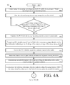
Referring now to FIGS. 4A-4B, there is provided a flow diagram of another exemplary method 400 for controlling access to a restricted area. As shown in FIG. 4A, method 400 begins with step 402 and continues with step 404 where an energy harvesting circuit (e.g., circuit 220 of FIG. 2) of a WAS (e.g., WAS 114 of FIG. 1) collects energy. The collected energy is then stored in an energy storage device (e.g., device 222 of FIG. 2) of the WAS as shown by step 406.
When the energy storage device charges to an operating voltage level of an SRC device (e.g., SRC device 212 of FIG. 2) of the WAS [408:YES], step 410 is performed where the WAS is transitioned from its energy harvesting mode to its communication mode. In its communication mode, step 412 is performed. Step 412 involves transmitting an SRC identifier signal from the WAS. The SRC identifier signal comprises a unique identifier and/or first information indicating a rate of change of the charging voltage of the energy storage device. The SRC identifier signal is then received in step 414 at an antenna (e.g., antenna 106 or 108 of FIG. 1) coupled to the reader.
In a next step 416, the direction and/or speed/velocity of motion of the person wearing the WAS is detected. One or more motion sensors (e.g., sensors 120 and/or 122 of FIG. 1) can be used in step 416 for said detection. Thereafter in step 418, second information is communicated to the reader specifying the detected direction and/or speed/velocity of the person's motion. The reader then communicates the following information to the DPS: the unique identifier; a time stamp; the first information; and/or the second information, as shown by step 420. After completing step 420, method 400 continues with step 422 of FIG. 4B.
At the DPS, operations are performed in step 422 to determine whether or not the person is attempting to enter or exit the restricted area using the information received in previous step 420. For example, if the received information indicates that the WAS is traveling towards an entrance antenna (e.g., antenna 108 of FIG. 1) and the person is moving in a first direction (e.g., direction 124 of FIG. 1), then a determination is made that the person desires to enter the restricted area via an access point (e.g., access point 102 of FIG. 1). In contrast, if the received information indicates that the WAS is traveling towards an exit antenna (e.g., antenna 106 of FIG. 1) and the person is moving in a direction opposite the first direction (e.g., direction 126 of FIG. 1), then a determination is made that the person desires to exit the restricted area via the access point. If the received information indicates that the WAS is traveling away from the entrance antenna, then a determination is made that the person is not trying to enter the restricted area. Similarly, if the received information indicates that the WAS is traveling away from the exit antenna, then a determination is made that the person is not trying to exit the restricted area. The present invention is not limited to the particulars of these examples. In this regard, it should be understood that the DPS additionally or alternatively analyzes patterns of motion defined by the received information to determine whether or not the person desires to enter or exit the access point.
After completing step 422, method 400 continues with decision step 424 of FIG. 4B. If it is determined that the person does not want to enter or exit the restricted area [424:NO], then step 426 is performed where the following information is logged in a data store: the unique identifier; a time stamp; the first information; the second information; and/or the third information indicating the results of the operations performed in previous step 422. Subsequently, step 444 is performed where method 400 ends or other processing is performed.
If it is determined that the person does want to enter or exit the restricted area [424:YES], then optional step 427 is performed. Optional step 427 is performed when the person is attempting to enter the restricted area, and therefore involves comparing the unique identifier with a plurality of unique identifiers stored in a data store to check whether the person is authorized to enter the restricted area. When a person is attempting to exit the restricted area or an authorized person is attempting to enter the restricted area, steps 428-434 are performed. These steps involve: causing a request for identification and location information to be sent to a PCD in a person's possession; performing operations by the PCD to obtain information useful for determining its current location within a surrounding environment; relaying the information obtained in step 430 to a remote device; and estimating a location of the PCD.
Upon completing step 434, step 436 is performed. In step 436, the DPS performs actions to cause actuation of a door opening actuator (e.g., door opening actuation 128 of FIG. 1). Next, steps 438-440 are performed to log the following information: the unique identifier; the time stamp; the first information; the second information; the third information; and/or the fourth information indicating that the person entered or exited the restricted area at a particular time. The logged information can optionally be used in step 442 to perform a historical analysis of the person's movement through a facility. Thereafter, step 444 is performed where method 400 ends or other processing is performed.
Additionally, in some scenarios, the WAS may detect no rate of change when the wearer is standing near the access point of a restricted area. For example, let's assume that a person travels towards the access point whereby the WAS detects a rate of change of the energy collected by the energy harvesting circuit thereof. When the person arrives at the access point, (s)he is stopped by another person for a discussion. At this time, the WAS detects no rate of change of the energy collected by the energy harvesting circuit thereof. In response to such a detection, the WAS communicates a signal to the reader (e.g., reader 104 of FIG. 1) indicating that there is currently no change in the rate at which the energy harvesting circuit is collecting energy. In turn, the reader performs operations to cause termination of the emission of an electromagnetic field from the entrance antenna (e.g., antenna 108 of FIG. 1). The electromagnetic field is once again emitted upon the expiration of a pre-defined period of time (e.g., 2 minutes). In this way, the person may still obtain access to the restricted area after finishing said discussion with the other person.
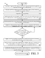
Referring now to FIG. 5, there is provided a flow diagram of an exemplary method 500 for operating a WAS (e.g., WAS 114 of FIG. 1). Method 500 begins with step 502 and continues with step 504 where RF energy is emitted within a surrounding environment from equipment disposed at an access point of a restricted area. Next in step 506, a person (e.g., person 116 of FIG. 1) wearing the WAS enters into the RF field at an operating frequency of an antenna of the WAS. As a result, RF energy is captured by the WAS as shown by step 508. The captured RF energy is passed through a switch of the WAS, as shown by step 510. The switch is normally in a position which provides an electrical connection or closed circuit between an antenna (e.g., antenna 202 of FIG. 2) and a full wave rectifier (e.g., full wave rectifier 252 of FIG. 2) of the WAS. An energy harvester power manager (e.g., energy harvester power manager 258 of FIG. 2) then performs operations in step 512 to convert the RF energy into direct current for generating electric power. The electric power is supplied to an energy storage device (e.g., energy storage device 262 of FIG. 2) of the WAS in step 514 for charging the same to a pre-determined voltage level. If the voltage of the energy storage device (e.g., a capacitor) is not equal to or greater than the pre-determined voltage level [516:NO], then method 500 returns to step 514 so that the energy storage device continues to be charged.
If the voltage of the energy storage device (e.g., a capacitor) is equal to or greater than the pre-determined voltage level [516:YES], then steps 518-522 are performed. These steps involve: supplying power from the energy storage device to a controller (e.g., controller 206 of FIG. 2) of the WAS via the energy harvester power manager and/or a voltage converter; generating and sending a switch control signal from the controller to the switch so as to cause the switch to change positions so as to be disconnected from the antenna and connected to a transceiver of the WAS; and communicating information from the WAS to a wireless edge device. In some scenarios, the information comprises user credentials that are useful for authenticating a user such that the user can be granted or denied access to a restricted area. Upon completing step 522, step 524 is performed where method 500 ends or other processing is performed.
All of the apparatus, methods, and algorithms disclosed and claimed herein can be made and executed without undue experimentation in light of the present disclosure. While the invention has been described in terms of preferred embodiments, it will be apparent to those having ordinary skill in the art that variations may be applied to the apparatus, methods and sequence of steps of the method without departing from the concept, spirit and scope of the invention. More specifically, it will be apparent that certain components may be added to, combined with, or substituted for the components described herein while the same or similar results would be achieved. All such similar substitutes and modifications apparent to those having ordinary skill in the art are deemed to be within the spirit, scope and concept of the invention as defined.
The features and functions disclosed above, as well as alternatives, may be combined into many other different systems or applications. Various presently unforeseen or unanticipated alternatives, modifications, variations or improvements may be made by those skilled in the art, each of which is also intended to be encompassed by the disclosed embodiments.

Claims (20)

We claim:
1. A method for operating a Wearable Access Sensor (“WAS”), comprising:
capturing RF energy by the WAS being worn by a person, where the RF energy is emitted within a surrounding environment from equipment disposed at an access point of a restricted area;
passing the RF energy through a switch that is normally in a position which provides an electrical connection between an antenna of the WAS and a full wave rectifier of the WAS;
performing operations by the WAS to convert the RF energy into direct current for generating electric power;
supplying the electric power to an energy storage device of the WAS for charging the energy storage device to a pre-determined voltage level; and
supplying power from the energy storage device to a controller of the WAS when a voltage level of the energy storage device is equal to or greater than the pre-determined voltage level.
2. The method according to claim 1, wherein the energy storage device comprises a super capacitor.
3. The method according to claim 1, further comprising generating and sending a switch control signal from the controller to the switch to cause the switch to change positions such that the switch is disconnected from the antenna and connected to a transceiver of the WAS.
4. The method according to claim 3, further comprising communicating information from the WAS to a wireless edge device.
5. The method according to claim 4, wherein the information comprises user credentials that are useful for authenticating a user such that the user can be granted or denied access to the restricted area.
6. The method according to claim 1, wherein the power is supplied from the energy storage device to the controller via a voltage converter that changes the pre-determined voltage level to a sub-threshold voltage level.
7. The method according to claim 1, further comprising increasing or decreasing, by a voltage converter of the WAS, a voltage level of a signal received from the energy storage device to a sub-threshold voltage level that is at least one order of magnitude below a normal operating range for the WAS, prior to supplying the power from the energy storage device to the controller.
8. The method according to claim 7, wherein the normal operating range of a voltage level is 1.2 Volts to 3.6 Volts.
9. The method according to claim 7, wherein the sub-threshold voltage level is within 200 milli-Volts to 600 milli-Volts.
10. The method according to claim 1, wherein a directionality of the WAS's movement is determined based on at least one of a rate of change of a charging voltage of the energy storage device and a detected direction of travel of the WAS in relation to the access point.
11. A Wearable Access Sensor (“WAS”), comprising:
an article wearable on a person;
an electronic circuit coupled to the article and comprising:
an antenna configured to capture RF energy emitted within a surrounding environment from equipment disposed at an access point of a restricted area;
a switch through which the RF energy passes, where the switch is normally in a position which provides an electrical connection between the antenna and a full wave rectifier;
said full wave rectifier configured to convert the RF energy into direct current for generating electric power and to supply the electric power to charge an energy storage device; and
an energy harvester power manager configured to supply power from the energy storage device to a controller when a voltage level of the energy storage device is equal to or greater than a pre-determined voltage level.
12. The WAS according to claim 11, wherein the energy storage device comprises a super capacitor.
13. The method according to claim 11, wherein the controller is configured to generate and send a switch control signal to the switch to cause the switch to change positions such that the switch is disconnected from the antenna and connected to a transceiver of the WAS.
14. The method according to claim 13, wherein the transceiver is configured to communicate information from the WAS to a wireless edge device.
15. The method according to claim 14, wherein the information comprises user credentials that are useful for authenticating a user such that the user can be granted or denied access to the restricted area.
16. The method according to claim 11, wherein the power is supplied from the energy storage device to the controller via a voltage converter that changes the pre-determined voltage level to a sub-threshold voltage level.
17. The method according to claim 11, wherein the voltage level of a signal received from the energy storage device is increased or decreased to a sub-threshold voltage level that is at least one order of magnitude below a normal operating range for the WAS, prior to when the power is supplied from the energy storage device to the controller.
18. The method according to claim 17, wherein the normal operating range of a voltage level is 1.2 Volts to 3.6 Volts.
19. The method according to claim 17, wherein the sub-threshold voltage level is within 200 milli-Volts to 600 milli-Volts.
20. The method according to claim 11, wherein a directionality of the WAS's movement is determined based on at least one of a rate of change of a charging voltage of the energy storage device and a detected direction of travel of the WAS in relation to the access point.
US14/956,803 2014-12-02 2015-12-02 Access control system using a wearable access sensory implementing an energy harvesting technique Active 2036-08-10 US9831724B2 (en)

Priority Applications (1)

Application Number Priority Date Filing Date Title
US14/956,803 US9831724B2 (en) 2014-12-02 2015-12-02 Access control system using a wearable access sensory implementing an energy harvesting technique

Applications Claiming Priority (3)

Application Number Priority Date Filing Date Title
US201462086241P 2014-12-02 2014-12-02
US201562219294P 2015-09-16 2015-09-16
US14/956,803 US9831724B2 (en) 2014-12-02 2015-12-02 Access control system using a wearable access sensory implementing an energy harvesting technique

Publications (2)

Publication Number Publication Date
US20160156219A1 US20160156219A1 (en) 2016-06-02
US9831724B2 true US9831724B2 (en) 2017-11-28

Family

ID=56079803

Family Applications (1)

Application Number Title Priority Date Filing Date
US14/956,803 Active 2036-08-10 US9831724B2 (en) 2014-12-02 2015-12-02 Access control system using a wearable access sensory implementing an energy harvesting technique

Country Status (1)

Country Link
US (1) US9831724B2 (en)

Cited By (21)

* Cited by examiner, † Cited by third party
Publication number Priority date Publication date Assignee Title
US10223516B2 (en) * 2016-06-09 2019-03-05 Lenovo (Singapore) Pte. Ltd. Login with linked wearable device
US10360419B1 (en) 2018-01-15 2019-07-23 Universal City Studios Llc Interactive systems and methods with tracking devices
US10537803B2 (en) 2018-01-18 2020-01-21 Universal City Studios Llc Interactive gaming system
US10603564B2 (en) 2018-01-03 2020-03-31 Universal City Studios Llc Interactive component for an amusement park
US10614271B2 (en) 2018-01-15 2020-04-07 Universal City Studios Llc Interactive systems and methods
US10653957B2 (en) 2017-12-06 2020-05-19 Universal City Studios Llc Interactive video game system
US10699084B2 (en) 2018-01-15 2020-06-30 Universal City Studios Llc Local interaction systems and methods
US10818152B2 (en) 2018-01-15 2020-10-27 Universal City Studios Llc Interactive systems and methods with feedback devices
US10839631B1 (en) 2017-03-01 2020-11-17 Alarm.Com Incorporated Authorized smart access to a monitored property
US10846967B2 (en) 2017-12-13 2020-11-24 Universal City Studio LLC Systems and methods for threshold detection of a wireless device
US10845975B2 (en) 2018-03-29 2020-11-24 Universal City Studios Llc Interactive animated character head systems and methods
US10916059B2 (en) 2017-12-06 2021-02-09 Universal City Studios Llc Interactive video game system having an augmented virtual representation
US10970725B2 (en) 2017-11-29 2021-04-06 Universal Studios LLC System and method for crowd management and maintenance operations
US10977583B2 (en) 2016-06-30 2021-04-13 Alarm.Com Incorporated Scheduled temporary rental property access
US11145016B1 (en) 2016-06-30 2021-10-12 Alarm.Com Incorporated Unattended smart property showing
US11755874B2 (en) 2021-03-03 2023-09-12 Sensormatic Electronics, LLC Methods and systems for heat applied sensor tag
US11769026B2 (en) 2019-11-27 2023-09-26 Sensormatic Electronics, LLC Flexible water-resistant sensor tag
US11861440B2 (en) 2019-09-18 2024-01-02 Sensormatic Electronics, LLC Systems and methods for providing tags adapted to be incorporated with or in items
US11869324B2 (en) 2021-12-23 2024-01-09 Sensormatic Electronics, LLC Securing a security tag into an article
US11928538B2 (en) 2019-09-18 2024-03-12 Sensormatic Electronics, LLC Systems and methods for laser tuning and attaching RFID tags to products
US11983596B2 (en) 2022-06-30 2024-05-14 Universal City Studios Llc Interactive systems and methods with tracking devices

Families Citing this family (2)

* Cited by examiner, † Cited by third party
Publication number Priority date Publication date Assignee Title
US10211679B1 (en) * 2015-08-31 2019-02-19 Spatiallink Corporation Hybrid source of energy supply scheme for internet of things system on chip
TWI773072B (en) * 2021-01-05 2022-08-01 亞旭電腦股份有限公司 Log in system and log in method of field

Citations (116)

* Cited by examiner, † Cited by third party
Publication number Priority date Publication date Assignee Title
US4325146A (en) 1979-12-20 1982-04-13 Lennington John W Non-synchronous object identification system
US4993068A (en) 1989-11-27 1991-02-12 Motorola, Inc. Unforgeable personal identification system
US5365266A (en) 1991-12-10 1994-11-15 Carpenter Loren C Video imaging method and apparatus for audience participation
US5387993A (en) 1993-06-25 1995-02-07 Precision Tracking Fm, Inc. Method for receiving and transmitting optical data and control information to and from remotely located receivers and transmitters in an optical locator system
US5502447A (en) 1993-10-28 1996-03-26 Hazeltine Corporation Beam sharpened pencil beam antenna systems
US5532705A (en) 1993-03-17 1996-07-02 Seiko Epson Corporation Wrist-mounted-type antenna device and apparatus having the antenna device
US5763868A (en) 1994-07-25 1998-06-09 Dai Nippon Printing Co., Ltd. Optical card
WO1999041721A1 (en) 1998-02-11 1999-08-19 Avery Dennison Corporation Label/tag with embedded signaling device and method and apparatus for making and using
US5947369A (en) 1995-09-21 1999-09-07 Temtec, Inc. Electronic time badge
US5960085A (en) 1997-04-14 1999-09-28 De La Huerga; Carlos Security badge for automated access control and secure data gathering
US5966227A (en) 1996-11-01 1999-10-12 Her Majesty The Queen In Right Of Canada, As Represented By The Minister Of National Defence Active cooperative tuned identification friend or foe (ACTIFF)
US5988645A (en) 1994-04-08 1999-11-23 Downing; Dennis L. Moving object monitoring system
US6219439B1 (en) 1998-07-09 2001-04-17 Paul M. Burger Biometric authentication system
US6288644B1 (en) 1998-09-01 2001-09-11 Caretaker System, Inc. Perimeter monitoring system
US6339999B1 (en) 1997-08-27 2002-01-22 Robert James Newell Detection of on-heat cows
US6346886B1 (en) 1996-12-20 2002-02-12 Carlos De La Huerga Electronic identification apparatus
US20020084904A1 (en) 1996-12-20 2002-07-04 Carlos De La Huerga Electronic identification apparatus
US20020140558A1 (en) 2001-03-29 2002-10-03 Ming-Ren Lian Manufacturing methods for magnetomechanical electronic article surveillance markers
US20030005193A1 (en) 2001-06-29 2003-01-02 Gadiel Seroussi Access control through secure channel using personal identification system
US20040085208A1 (en) 2002-10-29 2004-05-06 Shinichiro Fukuoka Article management system, noncontact electronic tag, article management method, and computer-readable medium
US6788262B1 (en) 2002-01-31 2004-09-07 The United States Of America As Represented By The Secretary Of The Navy Ultra-broadband antenna incorporated into a garment with radiation absorber material to mitigate radiation hazard
US20040246103A1 (en) 2003-06-04 2004-12-09 Pitney Bowes Incorporated Reusable electronic tag for secure data accumulation
US6888502B2 (en) 2002-03-05 2005-05-03 Precision Dynamics Corporation Microstrip antenna for an identification appliance
US20050168340A1 (en) 2002-03-18 2005-08-04 Mosher Walter W.Jr. Enhanced identification appliance having a plurality or data sets for authentication
US6950098B2 (en) 2001-07-03 2005-09-27 Barco N.V. Method and system for real time correction of an image
US20050285740A1 (en) 2004-03-17 2005-12-29 Uwe Kubach Proximity sensing
US20060022816A1 (en) 2004-07-30 2006-02-02 Mitsuhiko Yukawa Home security system
US20060219778A1 (en) 2005-04-05 2006-10-05 Kabushiki Kaisha Toshiba Authentication system, authentication method, and entrance/exit management system
US7119688B2 (en) 2001-05-25 2006-10-10 Hill-Rom Services, Inc. Waste segregation compliance system
US7202789B1 (en) * 2003-02-03 2007-04-10 Ingrid, Inc. Clip for RFID transponder of a security network
US20070182559A1 (en) 2005-09-15 2007-08-09 Zih Corp. Rfid antenna on multiple sides of 3-d packaging
US20080055045A1 (en) 2006-08-31 2008-03-06 3M Innovative Properties Company Rfid tag including a three-dimensional antenna
US20080074652A1 (en) 2006-09-15 2008-03-27 Fouquet Julie E Retroreflector-based system and method for detecting intrusion into a restricted area
US7424316B1 (en) 1999-07-29 2008-09-09 Nxp B.V. Body-worn personal communications apparatus
US7450024B2 (en) 2001-05-08 2008-11-11 Hill-Rom Services, Inc. Article locating and tracking apparatus and method
US7450077B2 (en) 2006-06-13 2008-11-11 Pharad, Llc Antenna for efficient body wearable applications
US20090121931A1 (en) 2007-11-12 2009-05-14 Katz Daniel A Wrist Worn Communication Device coupled with Antenna Extendable by the Arm
US7629934B2 (en) 2007-12-19 2009-12-08 Wireless Fibre Systems Wearable antenna
US20090322513A1 (en) 2008-06-27 2009-12-31 Franklin Dun-Jen Hwang Medical emergency alert system and method
US7696882B1 (en) 2007-02-21 2010-04-13 Impinj, Inc. Reading codes of RFID tags incoming at premises and removing them later as they exit
US20100315244A1 (en) 2009-06-12 2010-12-16 Ecolab USA Inc., Hand hygiene compliance monitoring
US20100328043A1 (en) 2008-02-29 2010-12-30 Nokia Corporation Interrogation of rfid communication units
US20110022121A1 (en) 2008-03-28 2011-01-27 Werner Meskins Antenna for behind-the-ear (bte) devices
US7898385B2 (en) 2002-06-26 2011-03-01 Robert William Kocher Personnel and vehicle identification system using three factors of authentication
US20110148602A1 (en) 2008-07-23 2011-06-23 Cadi Scientific Pte Ltd method and a system for determining the location of a subject, and a radio frequency identification tag assembly
US7982616B2 (en) 2008-02-14 2011-07-19 3M Innovative Properties Company Radio frequency identification (RFID) tag including a three-dimensional loop antenna
US7983565B2 (en) 2002-02-01 2011-07-19 Cubic Corporation Integrated optical communication and range finding system and application thereof
US20110206378A1 (en) 2005-06-20 2011-08-25 Bolling Steven F Hand cleanliness
US20110316700A1 (en) 2009-03-09 2011-12-29 Panasonic Corporation Device for detecting entry and/or exit monitoring device, and method for detecting entry and/or exit
US20120056719A1 (en) 2010-09-01 2012-03-08 Pattabhiraman Krishna UHF RFID wristband with a long read range
US20120189312A1 (en) 2010-07-19 2012-07-26 Cubic Corporation Near field combat identification
EP2495621A1 (en) 2011-03-03 2012-09-05 Winwatch IP Ltd Wristwatch including an RFID tag with antennas with split ring resonator (SRR) structure and/or meta-material antennas operating in the UHF and/or microwave frequency band and components of a watch provided with such an RFID tag
US8267325B2 (en) 2009-08-05 2012-09-18 Avery Dennison Corporation Wristband with elastic portion and inelastic portion containing a RFID inlay
US20120234921A1 (en) 2009-11-25 2012-09-20 Avery Dennison Corporation RFID Apparel Tag for Use in Industrial Processing and Post Care Treatment
US20120242481A1 (en) * 2011-03-22 2012-09-27 Tassilo Gernandt Apparatus and method for locating, tracking, controlling and recognizing tagged objects using active RFID technology.
US20120242501A1 (en) 2006-05-12 2012-09-27 Bao Tran Health monitoring appliance
US20120256492A1 (en) 2006-03-31 2012-10-11 Siemens Corporate Research, Inc. Passive RF Energy Harvesting Scheme For Wireless Sensor
US20120286927A1 (en) 2011-05-12 2012-11-15 Andreas Hagl Wake Channel Indication for Passive Entry System
US20130010962A1 (en) 2003-09-30 2013-01-10 Broadcom Corporation Proximity Authentication System
US20130027180A1 (en) 2010-03-02 2013-01-31 Vijaya Ramaraju Lakamraju Seamless authentication system
US8447188B2 (en) 2003-05-07 2013-05-21 Qinetiq Limited Dynamic optical reflector and interrogation system
US8497808B2 (en) 2011-04-08 2013-07-30 Wang Electro-Opto Corporation Ultra-wideband miniaturized omnidirectional antennas via multi-mode three-dimensional (3-D) traveling-wave (TW)
US20130221938A1 (en) 2012-02-29 2013-08-29 Stmicroelectronics S.R.L. Voltage regulator for contact-less electronic devices
US8599101B2 (en) 2010-01-27 2013-12-03 Sarantel Limited Dielectrically loaded antenna and radio communication apparatus
US8646695B2 (en) 2010-10-01 2014-02-11 Disney Enterprises, Inc. Combined HF and UHF RFID device
US20140068742A1 (en) * 2007-03-23 2014-03-06 Mastercard International Incorporated Pre-authenticated identification token
US8674810B2 (en) 2009-04-22 2014-03-18 Franwell, Inc. Wearable RFID system
US20140077929A1 (en) 2012-03-08 2014-03-20 Unikey Technologies, Inc. Wireless access control system and related methods
US20140159959A1 (en) 2012-07-11 2014-06-12 Digimarc Corporation Body-worn phased-array antenna
US20140159975A1 (en) 2012-08-14 2014-06-12 AMI Research & Development, LLC Wideband compact dipole manpack antenna
WO2014113882A1 (en) 2013-01-28 2014-07-31 Spielo International Canada Ulc Computer system and method for indoor geo-fencing and access control
US20140226844A1 (en) 2013-02-04 2014-08-14 Nxp B.V. Hearing aid antenna
US20140240087A1 (en) 2013-02-26 2014-08-28 Honeywell International Inc. Access Control System Using Smart Phone
US20140240088A1 (en) * 2011-03-22 2014-08-28 Jamie Robinette Apparatus and method for locating, tracking, controlling and recognizing tagged objects using active rfid technology
CN203825788U (en) 2014-05-14 2014-09-10 普天信息技术有限公司 Finger ring having vibration function
US20140327517A1 (en) 2011-10-11 2014-11-06 Johnson Controls Automotive Electronics Sas Remote control system, and method for automatically locking and/or unlocking at least one movable panel of a motor vehicle and/or for starting a motor vehicle engine using a remote control system
US20140354494A1 (en) 2013-06-03 2014-12-04 Daniel A. Katz Wrist Worn Device with Inverted F Antenna
US8917214B2 (en) 2011-03-16 2014-12-23 Avery Dennison Corporation Dual band RFID device and method of formulation
US20140375429A1 (en) 2007-07-27 2014-12-25 Lucomm Technologies, Inc. Systems and methods for object localization and path identification based on rfid sensing
WO2014210000A1 (en) 2013-06-24 2014-12-31 Avery Dennison Corporation Robust washable tags using a large area antenna conductor
US20150022321A1 (en) 2013-07-17 2015-01-22 Donald Keith Lefevre Long-Range Electronic Identification System
US20150041614A1 (en) 2013-08-09 2015-02-12 Motorola Solutions, Inc. Flexible mounting apparatus for mounting an antenna
WO2015023737A1 (en) 2013-08-15 2015-02-19 Unikey Technologies, Inc. Wireless access control system and related methods
US20150054696A1 (en) 2013-08-22 2015-02-26 The Penn State Research Foundation Antenna Apparatus and Communication System
US20150070134A1 (en) 2013-09-10 2015-03-12 Intel Corporation Authentication system using wearable device
US20150078741A1 (en) 2013-09-19 2015-03-19 eocys, LLC Devices and methods to produce and receive an encoded light signature
US8985439B2 (en) 2013-01-18 2015-03-24 Deetectee Microsystems Inc. Method of mobile optical recognition
US20150149310A1 (en) 2013-11-27 2015-05-28 Shenzhen Huiding Technology Co., Ltd. Wearable communication devices for secured transaction and communication
US20150154486A1 (en) 2013-12-02 2015-06-04 Cambridge Silicon Radio, Ltd. Protection of an nfc or rfid radio in the presence of strong electromagnetic fields
US20150168554A1 (en) 2012-08-09 2015-06-18 Israel Aerospace Industries Ltd. Friend or foe identification system and method
US20150180716A1 (en) 2013-07-30 2015-06-25 Google Inc. Mobile computing device and wearable computing device having automatic access mode control
US20150185160A1 (en) 2012-07-03 2015-07-02 Sicpa Holding Sa Capsule or cork comprising security features
US20150188632A1 (en) 2012-12-27 2015-07-02 Panasonic Intellectual Property Corporation Of America Information processing program, reception program, and information processing apparatus
US9076273B2 (en) 2012-02-24 2015-07-07 Identive Group, Inc. Method and system for providing identity, authentication, and access services
US20150221147A1 (en) 2013-03-15 2015-08-06 The Chamberlain Group, Inc. Remote Guest Access to a Secured Premises
US20150250419A1 (en) 2014-03-07 2015-09-10 Mondevices Inc. Subject motion monitoring, temperature monitoring, data gathering and analytics system and method
US20150264431A1 (en) 2014-03-14 2015-09-17 Aliphcom Presentation and recommendation of media content based on media content responses determined using sensor data
US20150280829A1 (en) 2014-03-25 2015-10-01 Osram Sylvania Inc. Multiple panel luminaires for light-based communication
US20150339870A1 (en) 2014-05-20 2015-11-26 Tyco Safety Products Canada Ltd. Dual Access Level Security System and Method
US20150341114A1 (en) 2007-05-24 2015-11-26 Federal Law Enforcement Development Services, Inc. LED Light Fixture
US20150365166A1 (en) 2014-06-13 2015-12-17 Google Inc. Optical communication for body mountable devices
US20150379791A1 (en) 2014-06-25 2015-12-31 Amazon Technologies, Inc. Wearable RFID Devices With Manually Activated RFID Tags
US20160007315A1 (en) 2011-02-24 2016-01-07 John C. Lundgreen Ranging system using active radio frequency (rf) nodes
US20160014103A1 (en) 2014-07-10 2016-01-14 Schweitzer Engineering Laboratories, Inc. Physical access control authentication
US20160055692A1 (en) 2014-08-19 2016-02-25 Sensormatic Electronics, LLC Method and system for access control proximity location
US20160095189A1 (en) 2014-09-29 2016-03-31 Koninklijke Philips N.V Systems and methods for lighting control
US20160164607A1 (en) 2007-05-24 2016-06-09 Federal Law Enforcement Development Services, Inc. Led light global positioning and routing communication system
US9384608B2 (en) 2014-12-03 2016-07-05 Tyco Fire & Security Gmbh Dual level human identification and location system
US20160267760A1 (en) 2014-08-19 2016-09-15 Sensormatic Electronics, LLC Video Recognition in Frictionless Access Control System
US20160284183A1 (en) 2014-08-19 2016-09-29 Sensormatic Electronics, LLC Tailgating Detection in Frictionless Access Control System
US20160294835A1 (en) 2015-03-31 2016-10-06 Lenovo (Singapore) Pte. Ltd. Initiating a Secure Action Via Physical Manipulation
US20160344091A1 (en) 2015-05-20 2016-11-24 Sensormatic Electronics, LLC Portable Device having Directional BLE Antenna
US9514584B1 (en) 2010-10-28 2016-12-06 Alarm.Com Incorporated Access management and reporting technology
US9519853B2 (en) 2013-11-01 2016-12-13 James P Tolle Wearable, non-visible identification device for friendly force identification and intruder detection
US9600999B2 (en) 2014-05-21 2017-03-21 Universal City Studios Llc Amusement park element tracking system
US20170228953A1 (en) * 2014-08-07 2017-08-10 8857911 Canada Inc. Proximity access control devices, systems and related methods

Patent Citations (120)

* Cited by examiner, † Cited by third party
Publication number Priority date Publication date Assignee Title
US4325146A (en) 1979-12-20 1982-04-13 Lennington John W Non-synchronous object identification system
US4993068A (en) 1989-11-27 1991-02-12 Motorola, Inc. Unforgeable personal identification system
US5365266A (en) 1991-12-10 1994-11-15 Carpenter Loren C Video imaging method and apparatus for audience participation
US5532705A (en) 1993-03-17 1996-07-02 Seiko Epson Corporation Wrist-mounted-type antenna device and apparatus having the antenna device
US5387993A (en) 1993-06-25 1995-02-07 Precision Tracking Fm, Inc. Method for receiving and transmitting optical data and control information to and from remotely located receivers and transmitters in an optical locator system
US5502447A (en) 1993-10-28 1996-03-26 Hazeltine Corporation Beam sharpened pencil beam antenna systems
US5988645A (en) 1994-04-08 1999-11-23 Downing; Dennis L. Moving object monitoring system
US5763868A (en) 1994-07-25 1998-06-09 Dai Nippon Printing Co., Ltd. Optical card
US5947369A (en) 1995-09-21 1999-09-07 Temtec, Inc. Electronic time badge
US5966227A (en) 1996-11-01 1999-10-12 Her Majesty The Queen In Right Of Canada, As Represented By The Minister Of National Defence Active cooperative tuned identification friend or foe (ACTIFF)
US6346886B1 (en) 1996-12-20 2002-02-12 Carlos De La Huerga Electronic identification apparatus
US20020084904A1 (en) 1996-12-20 2002-07-04 Carlos De La Huerga Electronic identification apparatus
US5960085A (en) 1997-04-14 1999-09-28 De La Huerga; Carlos Security badge for automated access control and secure data gathering
US6339999B1 (en) 1997-08-27 2002-01-22 Robert James Newell Detection of on-heat cows
WO1999041721A1 (en) 1998-02-11 1999-08-19 Avery Dennison Corporation Label/tag with embedded signaling device and method and apparatus for making and using
US6219439B1 (en) 1998-07-09 2001-04-17 Paul M. Burger Biometric authentication system
US6288644B1 (en) 1998-09-01 2001-09-11 Caretaker System, Inc. Perimeter monitoring system
US7424316B1 (en) 1999-07-29 2008-09-09 Nxp B.V. Body-worn personal communications apparatus
US20020140558A1 (en) 2001-03-29 2002-10-03 Ming-Ren Lian Manufacturing methods for magnetomechanical electronic article surveillance markers
US7450024B2 (en) 2001-05-08 2008-11-11 Hill-Rom Services, Inc. Article locating and tracking apparatus and method
US7119688B2 (en) 2001-05-25 2006-10-10 Hill-Rom Services, Inc. Waste segregation compliance system
US20030005193A1 (en) 2001-06-29 2003-01-02 Gadiel Seroussi Access control through secure channel using personal identification system
US6950098B2 (en) 2001-07-03 2005-09-27 Barco N.V. Method and system for real time correction of an image
US6788262B1 (en) 2002-01-31 2004-09-07 The United States Of America As Represented By The Secretary Of The Navy Ultra-broadband antenna incorporated into a garment with radiation absorber material to mitigate radiation hazard
US7983565B2 (en) 2002-02-01 2011-07-19 Cubic Corporation Integrated optical communication and range finding system and application thereof
US6888502B2 (en) 2002-03-05 2005-05-03 Precision Dynamics Corporation Microstrip antenna for an identification appliance
US7849619B2 (en) 2002-03-18 2010-12-14 Mosher Jr Walter W Enhanced identification appliance for verifying and authenticating the bearer through biometric data
US20050168340A1 (en) 2002-03-18 2005-08-04 Mosher Walter W.Jr. Enhanced identification appliance having a plurality or data sets for authentication
US7898385B2 (en) 2002-06-26 2011-03-01 Robert William Kocher Personnel and vehicle identification system using three factors of authentication
US20040085208A1 (en) 2002-10-29 2004-05-06 Shinichiro Fukuoka Article management system, noncontact electronic tag, article management method, and computer-readable medium
US7202789B1 (en) * 2003-02-03 2007-04-10 Ingrid, Inc. Clip for RFID transponder of a security network
US8447188B2 (en) 2003-05-07 2013-05-21 Qinetiq Limited Dynamic optical reflector and interrogation system
US20040246103A1 (en) 2003-06-04 2004-12-09 Pitney Bowes Incorporated Reusable electronic tag for secure data accumulation
US20130010962A1 (en) 2003-09-30 2013-01-10 Broadcom Corporation Proximity Authentication System
US20050285740A1 (en) 2004-03-17 2005-12-29 Uwe Kubach Proximity sensing
US20060022816A1 (en) 2004-07-30 2006-02-02 Mitsuhiko Yukawa Home security system
US20060219778A1 (en) 2005-04-05 2006-10-05 Kabushiki Kaisha Toshiba Authentication system, authentication method, and entrance/exit management system
US8502681B2 (en) 2005-06-20 2013-08-06 Biovigil, Llc Hand cleanliness
US20110206378A1 (en) 2005-06-20 2011-08-25 Bolling Steven F Hand cleanliness
US20070182559A1 (en) 2005-09-15 2007-08-09 Zih Corp. Rfid antenna on multiple sides of 3-d packaging
US20120256492A1 (en) 2006-03-31 2012-10-11 Siemens Corporate Research, Inc. Passive RF Energy Harvesting Scheme For Wireless Sensor
US20120242501A1 (en) 2006-05-12 2012-09-27 Bao Tran Health monitoring appliance
US7450077B2 (en) 2006-06-13 2008-11-11 Pharad, Llc Antenna for efficient body wearable applications
US20080055045A1 (en) 2006-08-31 2008-03-06 3M Innovative Properties Company Rfid tag including a three-dimensional antenna
US20080074652A1 (en) 2006-09-15 2008-03-27 Fouquet Julie E Retroreflector-based system and method for detecting intrusion into a restricted area
US7696882B1 (en) 2007-02-21 2010-04-13 Impinj, Inc. Reading codes of RFID tags incoming at premises and removing them later as they exit
US20140068742A1 (en) * 2007-03-23 2014-03-06 Mastercard International Incorporated Pre-authenticated identification token
US20170026118A1 (en) 2007-05-24 2017-01-26 Federal Law Enforcement Development Services, Inc. Building illumination apparatus with integrated communications, security and energy management
US20150341114A1 (en) 2007-05-24 2015-11-26 Federal Law Enforcement Development Services, Inc. LED Light Fixture
US20160164607A1 (en) 2007-05-24 2016-06-09 Federal Law Enforcement Development Services, Inc. Led light global positioning and routing communication system
US20140375429A1 (en) 2007-07-27 2014-12-25 Lucomm Technologies, Inc. Systems and methods for object localization and path identification based on rfid sensing
US20090121931A1 (en) 2007-11-12 2009-05-14 Katz Daniel A Wrist Worn Communication Device coupled with Antenna Extendable by the Arm
US7629934B2 (en) 2007-12-19 2009-12-08 Wireless Fibre Systems Wearable antenna
US7982616B2 (en) 2008-02-14 2011-07-19 3M Innovative Properties Company Radio frequency identification (RFID) tag including a three-dimensional loop antenna
US20100328043A1 (en) 2008-02-29 2010-12-30 Nokia Corporation Interrogation of rfid communication units
US20110022121A1 (en) 2008-03-28 2011-01-27 Werner Meskins Antenna for behind-the-ear (bte) devices
US20090322513A1 (en) 2008-06-27 2009-12-31 Franklin Dun-Jen Hwang Medical emergency alert system and method
US20110148602A1 (en) 2008-07-23 2011-06-23 Cadi Scientific Pte Ltd method and a system for determining the location of a subject, and a radio frequency identification tag assembly
US20110316700A1 (en) 2009-03-09 2011-12-29 Panasonic Corporation Device for detecting entry and/or exit monitoring device, and method for detecting entry and/or exit
US8674810B2 (en) 2009-04-22 2014-03-18 Franwell, Inc. Wearable RFID system
US20100315244A1 (en) 2009-06-12 2010-12-16 Ecolab USA Inc., Hand hygiene compliance monitoring
US8267325B2 (en) 2009-08-05 2012-09-18 Avery Dennison Corporation Wristband with elastic portion and inelastic portion containing a RFID inlay
US20120234921A1 (en) 2009-11-25 2012-09-20 Avery Dennison Corporation RFID Apparel Tag for Use in Industrial Processing and Post Care Treatment
US8599101B2 (en) 2010-01-27 2013-12-03 Sarantel Limited Dielectrically loaded antenna and radio communication apparatus
US20130027180A1 (en) 2010-03-02 2013-01-31 Vijaya Ramaraju Lakamraju Seamless authentication system
US20120189312A1 (en) 2010-07-19 2012-07-26 Cubic Corporation Near field combat identification
US20120056719A1 (en) 2010-09-01 2012-03-08 Pattabhiraman Krishna UHF RFID wristband with a long read range
US8646695B2 (en) 2010-10-01 2014-02-11 Disney Enterprises, Inc. Combined HF and UHF RFID device
US9514584B1 (en) 2010-10-28 2016-12-06 Alarm.Com Incorporated Access management and reporting technology
US20160007315A1 (en) 2011-02-24 2016-01-07 John C. Lundgreen Ranging system using active radio frequency (rf) nodes
EP2495621A1 (en) 2011-03-03 2012-09-05 Winwatch IP Ltd Wristwatch including an RFID tag with antennas with split ring resonator (SRR) structure and/or meta-material antennas operating in the UHF and/or microwave frequency band and components of a watch provided with such an RFID tag
US8917214B2 (en) 2011-03-16 2014-12-23 Avery Dennison Corporation Dual band RFID device and method of formulation
US20140240088A1 (en) * 2011-03-22 2014-08-28 Jamie Robinette Apparatus and method for locating, tracking, controlling and recognizing tagged objects using active rfid technology
US20120242481A1 (en) * 2011-03-22 2012-09-27 Tassilo Gernandt Apparatus and method for locating, tracking, controlling and recognizing tagged objects using active RFID technology.
US8497808B2 (en) 2011-04-08 2013-07-30 Wang Electro-Opto Corporation Ultra-wideband miniaturized omnidirectional antennas via multi-mode three-dimensional (3-D) traveling-wave (TW)
US20120286927A1 (en) 2011-05-12 2012-11-15 Andreas Hagl Wake Channel Indication for Passive Entry System
US20140327517A1 (en) 2011-10-11 2014-11-06 Johnson Controls Automotive Electronics Sas Remote control system, and method for automatically locking and/or unlocking at least one movable panel of a motor vehicle and/or for starting a motor vehicle engine using a remote control system
US9076273B2 (en) 2012-02-24 2015-07-07 Identive Group, Inc. Method and system for providing identity, authentication, and access services
US20130221938A1 (en) 2012-02-29 2013-08-29 Stmicroelectronics S.R.L. Voltage regulator for contact-less electronic devices
US20140077929A1 (en) 2012-03-08 2014-03-20 Unikey Technologies, Inc. Wireless access control system and related methods
US20150185160A1 (en) 2012-07-03 2015-07-02 Sicpa Holding Sa Capsule or cork comprising security features
US20140159959A1 (en) 2012-07-11 2014-06-12 Digimarc Corporation Body-worn phased-array antenna
US20150168554A1 (en) 2012-08-09 2015-06-18 Israel Aerospace Industries Ltd. Friend or foe identification system and method
US20140159975A1 (en) 2012-08-14 2014-06-12 AMI Research & Development, LLC Wideband compact dipole manpack antenna
US20150188632A1 (en) 2012-12-27 2015-07-02 Panasonic Intellectual Property Corporation Of America Information processing program, reception program, and information processing apparatus
US8985439B2 (en) 2013-01-18 2015-03-24 Deetectee Microsystems Inc. Method of mobile optical recognition
WO2014113882A1 (en) 2013-01-28 2014-07-31 Spielo International Canada Ulc Computer system and method for indoor geo-fencing and access control
US20140226844A1 (en) 2013-02-04 2014-08-14 Nxp B.V. Hearing aid antenna
US20140240087A1 (en) 2013-02-26 2014-08-28 Honeywell International Inc. Access Control System Using Smart Phone
US20150221147A1 (en) 2013-03-15 2015-08-06 The Chamberlain Group, Inc. Remote Guest Access to a Secured Premises
US20140354494A1 (en) 2013-06-03 2014-12-04 Daniel A. Katz Wrist Worn Device with Inverted F Antenna
WO2014210000A1 (en) 2013-06-24 2014-12-31 Avery Dennison Corporation Robust washable tags using a large area antenna conductor
US20150022321A1 (en) 2013-07-17 2015-01-22 Donald Keith Lefevre Long-Range Electronic Identification System
US20150180716A1 (en) 2013-07-30 2015-06-25 Google Inc. Mobile computing device and wearable computing device having automatic access mode control
US20150041614A1 (en) 2013-08-09 2015-02-12 Motorola Solutions, Inc. Flexible mounting apparatus for mounting an antenna
WO2015023737A1 (en) 2013-08-15 2015-02-19 Unikey Technologies, Inc. Wireless access control system and related methods
US20150054696A1 (en) 2013-08-22 2015-02-26 The Penn State Research Foundation Antenna Apparatus and Communication System
US20150070134A1 (en) 2013-09-10 2015-03-12 Intel Corporation Authentication system using wearable device
US20150078741A1 (en) 2013-09-19 2015-03-19 eocys, LLC Devices and methods to produce and receive an encoded light signature
US9519853B2 (en) 2013-11-01 2016-12-13 James P Tolle Wearable, non-visible identification device for friendly force identification and intruder detection
US20150149310A1 (en) 2013-11-27 2015-05-28 Shenzhen Huiding Technology Co., Ltd. Wearable communication devices for secured transaction and communication
US20150154486A1 (en) 2013-12-02 2015-06-04 Cambridge Silicon Radio, Ltd. Protection of an nfc or rfid radio in the presence of strong electromagnetic fields
US20150250419A1 (en) 2014-03-07 2015-09-10 Mondevices Inc. Subject motion monitoring, temperature monitoring, data gathering and analytics system and method
US20150264431A1 (en) 2014-03-14 2015-09-17 Aliphcom Presentation and recommendation of media content based on media content responses determined using sensor data
US20150280829A1 (en) 2014-03-25 2015-10-01 Osram Sylvania Inc. Multiple panel luminaires for light-based communication
CN203825788U (en) 2014-05-14 2014-09-10 普天信息技术有限公司 Finger ring having vibration function
US20150339870A1 (en) 2014-05-20 2015-11-26 Tyco Safety Products Canada Ltd. Dual Access Level Security System and Method
US9600999B2 (en) 2014-05-21 2017-03-21 Universal City Studios Llc Amusement park element tracking system
US20150365166A1 (en) 2014-06-13 2015-12-17 Google Inc. Optical communication for body mountable devices
US20150379791A1 (en) 2014-06-25 2015-12-31 Amazon Technologies, Inc. Wearable RFID Devices With Manually Activated RFID Tags
US20160014103A1 (en) 2014-07-10 2016-01-14 Schweitzer Engineering Laboratories, Inc. Physical access control authentication
US20170228953A1 (en) * 2014-08-07 2017-08-10 8857911 Canada Inc. Proximity access control devices, systems and related methods
US20160284183A1 (en) 2014-08-19 2016-09-29 Sensormatic Electronics, LLC Tailgating Detection in Frictionless Access Control System
US20160267760A1 (en) 2014-08-19 2016-09-15 Sensormatic Electronics, LLC Video Recognition in Frictionless Access Control System
US20160055692A1 (en) 2014-08-19 2016-02-25 Sensormatic Electronics, LLC Method and system for access control proximity location
US20160095189A1 (en) 2014-09-29 2016-03-31 Koninklijke Philips N.V Systems and methods for lighting control
US9384608B2 (en) 2014-12-03 2016-07-05 Tyco Fire & Security Gmbh Dual level human identification and location system
US20160294835A1 (en) 2015-03-31 2016-10-06 Lenovo (Singapore) Pte. Ltd. Initiating a Secure Action Via Physical Manipulation
US20160344091A1 (en) 2015-05-20 2016-11-24 Sensormatic Electronics, LLC Portable Device having Directional BLE Antenna
US20160343187A1 (en) 2015-05-20 2016-11-24 Sensormatic Electronics, LLC Frictionless Access System for Public Access Point

Non-Patent Citations (6)

* Cited by examiner, † Cited by third party
Title
Conway, G.A., et al., "Antennas for Over-Body-Surface Communication at 2.45 GHz," IEEE Transactions on Antennas and Propagation, vol. 57, No. 4, Apr. 2009, 0018-926X, copyright 2009 IEEE.
Hall, P.S., et al., "Antennas and Propagation for Body Centric Communications," Proc. 'EUCAP 2006', Nice, France, Nov. 6-10, 2006 (ESA SP-626, Oct. 2006).
Hall, P.S., et al., "Antennas and Propagation for Body Centric Communications," Proc. ‘EUCAP 2006’, Nice, France, Nov. 6-10, 2006 (ESA SP-626, Oct. 2006).
Ito, K., et al., "Wearable Antennas for Body-Centric Wireless Communications," copyright IEEE 2010; 978-1-4244-6418-0/10.
Matthews, J.C.G., et al., "Body Wearable Antennas for UHF/VHF," 2008 Loughborough Antennas & Propagation Conference, 978-1-4244-1894-7/08, copyright 2008 IEEE.
Rais, N.H.M., et al., "A Review of Wearable Antenna," Antennas & Propagation Conference, 2009, LAPC 2009, Loughborough, Published IEEE; 978-1-4244-2720-8; DOI: 10.1109/LAPC.2009.5352373.

Cited By (30)

* Cited by examiner, † Cited by third party
Publication number Priority date Publication date Assignee Title
US10223516B2 (en) * 2016-06-09 2019-03-05 Lenovo (Singapore) Pte. Ltd. Login with linked wearable device
US11861750B2 (en) 2016-06-30 2024-01-02 Alarm.Com Incorporated Unattended smart property showing
US11145016B1 (en) 2016-06-30 2021-10-12 Alarm.Com Incorporated Unattended smart property showing
US10977583B2 (en) 2016-06-30 2021-04-13 Alarm.Com Incorporated Scheduled temporary rental property access
US10839631B1 (en) 2017-03-01 2020-11-17 Alarm.Com Incorporated Authorized smart access to a monitored property
US11501590B2 (en) 2017-03-01 2022-11-15 Alarm.Com Incorporated Authorized smart access to a monitored property
US11694217B2 (en) 2017-11-29 2023-07-04 Universal City Studios Llc System and method for crowd management and maintenance operations
US10970725B2 (en) 2017-11-29 2021-04-06 Universal Studios LLC System and method for crowd management and maintenance operations
US11682172B2 (en) 2017-12-06 2023-06-20 Universal City Studios Llc Interactive video game system having an augmented virtual representation
US10916059B2 (en) 2017-12-06 2021-02-09 Universal City Studios Llc Interactive video game system having an augmented virtual representation
US11400371B2 (en) 2017-12-06 2022-08-02 Universal City Studios Llc Interactive video game system
US10653957B2 (en) 2017-12-06 2020-05-19 Universal City Studios Llc Interactive video game system
US10846967B2 (en) 2017-12-13 2020-11-24 Universal City Studio LLC Systems and methods for threshold detection of a wireless device
US11130038B2 (en) 2018-01-03 2021-09-28 Universal City Studios Llc Interactive component for an amusement park
US10603564B2 (en) 2018-01-03 2020-03-31 Universal City Studios Llc Interactive component for an amusement park
US10699084B2 (en) 2018-01-15 2020-06-30 Universal City Studios Llc Local interaction systems and methods
US10839178B2 (en) 2018-01-15 2020-11-17 Universal City Studios Llc Interactive systems and methods with tracking devices
US11379678B2 (en) 2018-01-15 2022-07-05 Universal City Studios Llc Local interaction systems and methods
US11379679B2 (en) 2018-01-15 2022-07-05 Universal City Studios Llc Interactive systems and methods with tracking devices
US10818152B2 (en) 2018-01-15 2020-10-27 Universal City Studios Llc Interactive systems and methods with feedback devices
US10614271B2 (en) 2018-01-15 2020-04-07 Universal City Studios Llc Interactive systems and methods
US10360419B1 (en) 2018-01-15 2019-07-23 Universal City Studios Llc Interactive systems and methods with tracking devices
US10537803B2 (en) 2018-01-18 2020-01-21 Universal City Studios Llc Interactive gaming system
US10845975B2 (en) 2018-03-29 2020-11-24 Universal City Studios Llc Interactive animated character head systems and methods
US11861440B2 (en) 2019-09-18 2024-01-02 Sensormatic Electronics, LLC Systems and methods for providing tags adapted to be incorporated with or in items
US11928538B2 (en) 2019-09-18 2024-03-12 Sensormatic Electronics, LLC Systems and methods for laser tuning and attaching RFID tags to products
US11769026B2 (en) 2019-11-27 2023-09-26 Sensormatic Electronics, LLC Flexible water-resistant sensor tag
US11755874B2 (en) 2021-03-03 2023-09-12 Sensormatic Electronics, LLC Methods and systems for heat applied sensor tag
US11869324B2 (en) 2021-12-23 2024-01-09 Sensormatic Electronics, LLC Securing a security tag into an article
US11983596B2 (en) 2022-06-30 2024-05-14 Universal City Studios Llc Interactive systems and methods with tracking devices

Also Published As

Publication number Publication date
US20160156219A1 (en) 2016-06-02

Similar Documents

Publication Publication Date Title
US9831724B2 (en) Access control system using a wearable access sensory implementing an energy harvesting technique
CA2972425C (en) Passive rfid tags with integrated circuits using sub-threshold technology
US9384607B1 (en) Access control system
US9384608B2 (en) Dual level human identification and location system
CN105931326B (en) A kind of access control device and method
US9710978B1 (en) Access control system using optical communication protocol
CN103052974B (en) Method and device for prevention loss of item and prompt search thereof
CN105279824B (en) Tripper
US20150210505A1 (en) Elevator call registering system
CN103988213A (en) Antenna interface for radio frequency identification circuit
CN108763993A (en) The noninductive control methods of RFID based on range sensor, apparatus and system
US20070252208A1 (en) Semiconductor device and position detecting method using the semiconductor device
AU2015358535B2 (en) Dual level human identification and location system
CN208314799U (en) The noninductive control device of RFID and system based on range sensor
KR20070005277A (en) Elevator controller using rfid tag
KR20150112686A (en) Management of gates using FRID system
CN106646340A (en) Door entrance and exit electronic equipment identification system on basis of directional antennas
CN118038582A (en) Authentication system, learning device method, learning program, reasoning device, reasoning method, and reasoning program
CN108780515B (en) Label, authentication system, electronic lock control system, automatic door control system, and elevator control system
CN106910265A (en) Distance entrance and control method

Legal Events

Date Code Title Description
AS Assignment

Owner name: TYCO FIRE & SECURITY GMBH, SWITZERLAND

Free format text: ASSIGNMENT OF ASSIGNORS INTEREST;ASSIGNORS:COPELAND, RICHARD L.;SEQUEIRA, MELWYN F.;SIGNING DATES FROM 20151123 TO 20151201;REEL/FRAME:037190/0173

STCF Information on status: patent grant

Free format text: PATENTED CASE

AS Assignment

Owner name: SENSORMATIC ELECTRONICS, LLC, FLORIDA

Free format text: ASSIGNMENT OF ASSIGNORS INTEREST;ASSIGNOR:TYCO FIRE & SECURITY GMBH;REEL/FRAME:047182/0674

Effective date: 20180927

AS Assignment

Owner name: SENSORMATIC ELECTRONICS, LLC, FLORIDA

Free format text: ASSIGNMENT OF ASSIGNORS INTEREST;ASSIGNOR:TYCO FIRE & SECURITY GMBH;REEL/FRAME:047188/0715

Effective date: 20180927

MAFP Maintenance fee payment

Free format text: PAYMENT OF MAINTENANCE FEE, 4TH YEAR, LARGE ENTITY (ORIGINAL EVENT CODE: M1551); ENTITY STATUS OF PATENT OWNER: LARGE ENTITY

Year of fee payment: 4