US9499348B2 - Material handling conveyor vehicle - Google Patents
Material handling conveyor vehicle Download PDFInfo
- Publication number
- US9499348B2 US9499348B2 US14/286,488 US201414286488A US9499348B2 US 9499348 B2 US9499348 B2 US 9499348B2 US 201414286488 A US201414286488 A US 201414286488A US 9499348 B2 US9499348 B2 US 9499348B2
- Authority
- US
- United States
- Prior art keywords
- conveyor
- vehicle
- wheels
- support arms
- chassis
- Prior art date
- Legal status (The legal status is an assumption and is not a legal conclusion. Google has not performed a legal analysis and makes no representation as to the accuracy of the status listed.)
- Active, expires
Links
- 239000000463 material Substances 0.000 title claims abstract description 85
- 230000005484 gravity Effects 0.000 claims description 8
- 230000033001 locomotion Effects 0.000 claims description 8
- 238000000926 separation method Methods 0.000 claims description 3
- 238000005096 rolling process Methods 0.000 claims 1
- 239000012530 fluid Substances 0.000 abstract description 25
- 239000000428 dust Substances 0.000 abstract description 21
- 230000005540 biological transmission Effects 0.000 abstract description 14
- 239000013590 bulk material Substances 0.000 description 21
- 238000012546 transfer Methods 0.000 description 19
- 230000007246 mechanism Effects 0.000 description 12
- 239000008187 granular material Substances 0.000 description 9
- 239000004576 sand Substances 0.000 description 4
- 238000003825 pressing Methods 0.000 description 3
- 230000000712 assembly Effects 0.000 description 2
- 238000000429 assembly Methods 0.000 description 2
- 230000008878 coupling Effects 0.000 description 2
- 238000010168 coupling process Methods 0.000 description 2
- 238000005859 coupling reaction Methods 0.000 description 2
- 238000007599 discharging Methods 0.000 description 2
- 230000000694 effects Effects 0.000 description 2
- 239000002184 metal Substances 0.000 description 2
- 230000000116 mitigating effect Effects 0.000 description 2
- 230000007935 neutral effect Effects 0.000 description 2
- 208000010392 Bone Fractures Diseases 0.000 description 1
- 206010017076 Fracture Diseases 0.000 description 1
- 239000004677 Nylon Substances 0.000 description 1
- 208000002565 Open Fractures Diseases 0.000 description 1
- 201000010001 Silicosis Diseases 0.000 description 1
- 210000001015 abdomen Anatomy 0.000 description 1
- 230000009471 action Effects 0.000 description 1
- 238000004873 anchoring Methods 0.000 description 1
- 238000013459 approach Methods 0.000 description 1
- 238000009835 boiling Methods 0.000 description 1
- 239000000919 ceramic Substances 0.000 description 1
- 238000004891 communication Methods 0.000 description 1
- 230000007423 decrease Effects 0.000 description 1
- 230000003247 decreasing effect Effects 0.000 description 1
- 238000013461 design Methods 0.000 description 1
- 239000013070 direct material Substances 0.000 description 1
- 238000005553 drilling Methods 0.000 description 1
- 230000003028 elevating effect Effects 0.000 description 1
- 238000001125 extrusion Methods 0.000 description 1
- 230000036541 health Effects 0.000 description 1
- 238000010438 heat treatment Methods 0.000 description 1
- 238000002844 melting Methods 0.000 description 1
- 230000008018 melting Effects 0.000 description 1
- 238000000034 method Methods 0.000 description 1
- 238000012986 modification Methods 0.000 description 1
- 230000004048 modification Effects 0.000 description 1
- 229920003052 natural elastomer Polymers 0.000 description 1
- 229920001194 natural rubber Polymers 0.000 description 1
- 229920001778 nylon Polymers 0.000 description 1
- 230000008569 process Effects 0.000 description 1
- 230000009467 reduction Effects 0.000 description 1
- 239000012858 resilient material Substances 0.000 description 1
- 230000000284 resting effect Effects 0.000 description 1
- 230000000717 retained effect Effects 0.000 description 1
- 239000011435 rock Substances 0.000 description 1
- 238000004904 shortening Methods 0.000 description 1
- 229920003051 synthetic elastomer Polymers 0.000 description 1
- 239000005061 synthetic rubber Substances 0.000 description 1
- XLYOFNOQVPJJNP-UHFFFAOYSA-N water Substances O XLYOFNOQVPJJNP-UHFFFAOYSA-N 0.000 description 1
Images


Classifications
-
- B—PERFORMING OPERATIONS; TRANSPORTING
- B65—CONVEYING; PACKING; STORING; HANDLING THIN OR FILAMENTARY MATERIAL
- B65G—TRANSPORT OR STORAGE DEVICES, e.g. CONVEYORS FOR LOADING OR TIPPING, SHOP CONVEYOR SYSTEMS OR PNEUMATIC TUBE CONVEYORS
- B65G37/00—Combinations of mechanical conveyors of the same kind, or of different kinds, of interest apart from their application in particular machines or use in particular manufacturing processes
-
- B—PERFORMING OPERATIONS; TRANSPORTING
- B60—VEHICLES IN GENERAL
- B60K—ARRANGEMENT OR MOUNTING OF PROPULSION UNITS OR OF TRANSMISSIONS IN VEHICLES; ARRANGEMENT OR MOUNTING OF PLURAL DIVERSE PRIME-MOVERS IN VEHICLES; AUXILIARY DRIVES FOR VEHICLES; INSTRUMENTATION OR DASHBOARDS FOR VEHICLES; ARRANGEMENTS IN CONNECTION WITH COOLING, AIR INTAKE, GAS EXHAUST OR FUEL SUPPLY OF PROPULSION UNITS IN VEHICLES
- B60K17/00—Arrangement or mounting of transmissions in vehicles
- B60K17/04—Arrangement or mounting of transmissions in vehicles characterised by arrangement, location, or kind of gearing
- B60K17/10—Arrangement or mounting of transmissions in vehicles characterised by arrangement, location, or kind of gearing of fluid gearing
-
- B—PERFORMING OPERATIONS; TRANSPORTING
- B62—LAND VEHICLES FOR TRAVELLING OTHERWISE THAN ON RAILS
- B62D—MOTOR VEHICLES; TRAILERS
- B62D11/00—Steering non-deflectable wheels; Steering endless tracks or the like
- B62D11/02—Steering non-deflectable wheels; Steering endless tracks or the like by differentially driving ground-engaging elements on opposite vehicle sides
-
- B—PERFORMING OPERATIONS; TRANSPORTING
- B62—LAND VEHICLES FOR TRAVELLING OTHERWISE THAN ON RAILS
- B62D—MOTOR VEHICLES; TRAILERS
- B62D17/00—Means on vehicles for adjusting camber, castor, or toe-in
-
- B—PERFORMING OPERATIONS; TRANSPORTING
- B62—LAND VEHICLES FOR TRAVELLING OTHERWISE THAN ON RAILS
- B62D—MOTOR VEHICLES; TRAILERS
- B62D7/00—Steering linkage; Stub axles or their mountings
- B62D7/06—Steering linkage; Stub axles or their mountings for individually-pivoted wheels, e.g. on king-pins
-
- B—PERFORMING OPERATIONS; TRANSPORTING
- B65—CONVEYING; PACKING; STORING; HANDLING THIN OR FILAMENTARY MATERIAL
- B65G—TRANSPORT OR STORAGE DEVICES, e.g. CONVEYORS FOR LOADING OR TIPPING, SHOP CONVEYOR SYSTEMS OR PNEUMATIC TUBE CONVEYORS
- B65G41/00—Supporting frames or bases for conveyors as a whole, e.g. transportable conveyor frames
- B65G41/001—Supporting frames or bases for conveyors as a whole, e.g. transportable conveyor frames with the conveyor adjustably mounted on the supporting frame or base
- B65G41/002—Pivotably mounted
-
- B—PERFORMING OPERATIONS; TRANSPORTING
- B65—CONVEYING; PACKING; STORING; HANDLING THIN OR FILAMENTARY MATERIAL
- B65G—TRANSPORT OR STORAGE DEVICES, e.g. CONVEYORS FOR LOADING OR TIPPING, SHOP CONVEYOR SYSTEMS OR PNEUMATIC TUBE CONVEYORS
- B65G41/00—Supporting frames or bases for conveyors as a whole, e.g. transportable conveyor frames
- B65G41/007—Means for moving conveyor frames and control arrangements therefor
- B65G41/008—Means for moving conveyor frames and control arrangements therefor frames mounted on wheels or caterpillar
-
- B—PERFORMING OPERATIONS; TRANSPORTING
- B65—CONVEYING; PACKING; STORING; HANDLING THIN OR FILAMENTARY MATERIAL
- B65G—TRANSPORT OR STORAGE DEVICES, e.g. CONVEYORS FOR LOADING OR TIPPING, SHOP CONVEYOR SYSTEMS OR PNEUMATIC TUBE CONVEYORS
- B65G47/00—Article or material-handling devices associated with conveyors; Methods employing such devices
- B65G47/02—Devices for feeding articles or materials to conveyors
- B65G47/16—Devices for feeding articles or materials to conveyors for feeding materials in bulk
- B65G47/18—Arrangements or applications of hoppers or chutes
-
- B—PERFORMING OPERATIONS; TRANSPORTING
- B65—CONVEYING; PACKING; STORING; HANDLING THIN OR FILAMENTARY MATERIAL
- B65G—TRANSPORT OR STORAGE DEVICES, e.g. CONVEYORS FOR LOADING OR TIPPING, SHOP CONVEYOR SYSTEMS OR PNEUMATIC TUBE CONVEYORS
- B65G65/00—Loading or unloading
- B65G65/30—Methods or devices for filling or emptying bunkers, hoppers, tanks, or like containers, of interest apart from their use in particular chemical or physical processes or their application in particular machines, e.g. not covered by a single other subclass
- B65G65/34—Emptying devices
- B65G65/40—Devices for emptying otherwise than from the top
- B65G65/42—Devices for emptying otherwise than from the top using belt or chain conveyors
- B65G65/425—Devices for emptying otherwise than from the top using belt or chain conveyors arranged to be movable
-
- B—PERFORMING OPERATIONS; TRANSPORTING
- B65—CONVEYING; PACKING; STORING; HANDLING THIN OR FILAMENTARY MATERIAL
- B65G—TRANSPORT OR STORAGE DEVICES, e.g. CONVEYORS FOR LOADING OR TIPPING, SHOP CONVEYOR SYSTEMS OR PNEUMATIC TUBE CONVEYORS
- B65G69/00—Auxiliary measures taken, or devices used, in connection with loading or unloading
- B65G69/18—Preventing escape of dust
- B65G69/185—Preventing escape of dust by means of non-sealed systems
-
- B—PERFORMING OPERATIONS; TRANSPORTING
- B65—CONVEYING; PACKING; STORING; HANDLING THIN OR FILAMENTARY MATERIAL
- B65G—TRANSPORT OR STORAGE DEVICES, e.g. CONVEYORS FOR LOADING OR TIPPING, SHOP CONVEYOR SYSTEMS OR PNEUMATIC TUBE CONVEYORS
- B65G2207/00—Indexing codes relating to constructional details, configuration and additional features of a handling device, e.g. Conveyors
- B65G2207/40—Safety features of loads, equipment or persons
Definitions
- the present invention pertains in general to bulk material handling systems and in particular to mobile conveyor systems for moving bulk granular material from one location to another.
- Granular material such as sand or hydraulic fracturing proppant
- fracturing fluid along with a granular proppant material such as sand and/or ceramics, is pumped into a drill well to create and prop open fractures in rock.
- activities requiring large amounts of granular material are performed in a remote location, requiring granular material to be shipped in for example by road, rail or water.
- One component of an on-site mobile granular material delivery system is a mobile conveyor, which receives the material from a source such as a delivery truck, barge or rail car and conveys the material to an elevated location such as the input of a storage container.
- a mobile conveyor which receives the material from a source such as a delivery truck, barge or rail car and conveys the material to an elevated location such as the input of a storage container.
- existing mobile conveyors can suffer from a variety of drawbacks, such complexity of operation potentially requiring a large number of personnel, and various mechanical design limitations that can limit performance of the delivery system.
- An object of the present invention is to provide a vehicle for conveying bulk granular material.
- a mobile conveyor vehicle for transporting material comprising: a chassis; a first conveyor system mounted to the chassis and non-rotatable horizontally relative to the chassis; a second conveyor system mounted to the chassis and rotatable relative to the chassis in the horizontal direction, the second conveyor system cooperating with the first conveyor system to transport the material; and a steerable, powered drive system supporting the chassis and configured for both transporting the vehicle and rotating the vehicle, wherein rotation of the vehicle causes corresponding rotation of the first conveyor system for position control thereof.
- a dust control apparatus for a telescopic conveyor system, the conveyor system including an upper conveyor section for delivering material from an input end to a transfer end, and a lower conveyor section in telescoping relation with the upper conveyor section; the apparatus comprising: a cover mounted overtop of the lower conveyor section, the cover comprising a pair of separate, flexible sections mounted on opposite sides of the lower conveyor section and extending toward one another; and a material transfer chute mounted at the transfer end of the upper conveyor section, the chute having an outer surface shaped to interpose between and force apart the flexible sections of the cover, the chute defining an internal aperture for flow of the material from the transfer end of the upper conveyor section onto the lower conveyor section.
- a hydraulic fluid transmission system for a mobile conveyor vehicle for transporting material including a conveyor section comprising a structural frame and a source of hydraulic fluid, the hydraulic fluid transmission system comprising at least one hollow metallic member forming a structural element of the structural frame, the at least one hollow metallic member extending along a length of the conveyor section, wherein the hollow metallic member is operatively coupled to the source of hydraulic fluid and is configured to operate as a hydraulic fluid transmission line, and further wherein the hollow metallic member is configured to radiate excess heat from the hydraulic fluid.
- FIGS. 1 a to 1 d illustrates a conveyor vehicle provided in accordance with one embodiment of the invention.
- FIG. 2 illustrates a top view of the conveyor vehicle of FIGS. 1 a to 1 d.
- FIGS. 3 aa , 3 ab , 3 b and 3 c illustrate a dust control apparatus provided in accordance with one embodiment of the invention.
- FIGS. 4 aa , 4 ab and 4 b to 4 d illustrate a cross sectional views of the flexible sections of the dust control apparatus of FIGS. 3 aa , 3 ab , 3 b and 3 c , in accordance with various embodiments of the invention.
- FIGS. 5 a and 5 b illustrate a hydraulic fluid transmission system provided in accordance with one embodiment of the invention.
- FIG. 6 illustrates a bulk material delivery, handling and storage system comprising a mobile conveyor vehicle provided in accordance with one embodiment of the invention.
- the term “about” refers to a +/ ⁇ 10% variation from the nominal value. It is to be understood that such a variation is always included in a given value provided herein, whether or not it is specifically referred to.
- the present invention generally provides for aspects of a conveyor vehicle for transporting bulk material, such as sand, proppant, or the like.
- the vehicle includes a system of conveyors for transporting the material and a drive system for moving the vehicle relative to the ground, and aspects of the present invention may relate to one or both of the conveyor system and the drive system, as will be discussed in more detail below.
- An aspect of the present invention provides for a steerable, powered drive system of a mobile conveyor vehicle which is configured for both transporting the vehicle and rotating the vehicle, for example for relocating the conveyor or conveyors of the vehicle.
- the drive system may include a four-wheel steering component for rotation of the vehicle about a predetermined or selected pivot point.
- the pivot point may be vertically aligned with a point on the vehicle, such that this point on the vehicle remains substantially stationary while the vehicle rotates.
- the rotation is described as rotation-in-place of the vehicle. More particularly, rotation of the vehicle is configured to cause corresponding rotation of one of the conveyor systems mounted to and extending from the vehicle, thereby facilitating desired positioning of a distal end of this conveyor system.
- This conveyor system may therefore be non-rotatably mounted to the vehicle chassis, which eliminates the requirement for a powered turntable for rotating the conveyor while the vehicle chassis remains stationary. This may also simplify the requirements for counterweights which counterbalance this conveyor system relative to the vehicle chassis.
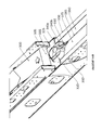
- FIGS. 1 a to 1 c illustrate a conveyor vehicle provided in accordance with an embodiment of the invention.
- the vehicle includes an infeed conveyor 110 and an output conveyor 120 which cooperate to transport bulk material from a distal end 112 of the infeed conveyor to a distal end 122 of the output conveyor.
- Material is received at the distal end 112 and is conveyed, for example by powered belt conveyor, along the infeed conveyor and off of an output end 114 of the infeed conveyor for receipt, via gravity, by a receiving portion 124 of the output conveyor, either at an end or interior portion thereof. It is then conveyed by another belt conveyor along the output conveyor and off of the distal end 122 to a target container proximate to the conveyor vehicle.
- Various forms and types of belt conveyors may be provided.
- belt conveyors may have a substantially flat or concave cross section, for example a V-shaped or U-Shaped cross section, possibly mounted on corresponding V-shaped or U-shaped roller assemblies.
- Belt conveyors may include features such as ledges formed across the width of the conveyor to assist in moving bulk material.
- Position of the infeed conveyor 110 is adjustable relative to the remainder of the vehicle by use of suitable drive systems.
- the infeed conveyor 110 is mounted on a powered turntable 135 configured for rotating the infeed conveyor relative to the vehicle.
- At least one hydraulic cylinder 137 or more typically a pair of hydraulic cylinders located on opposite sides of the conveyor, or similar mechanical actuator is provided for raising and lowering the infeed conveyor.
- the infeed conveyor may be a telescoping conveyor comprising an upper section 116 movable relative to a lower section 117 under mechanical power of a telescoping drive mechanism such as a rack and pinion mechanism or a hydraulic system.
- the upper section may be supported overtop of the upper section and generally parallel thereto.
- the upper section may be made to move in a longitudinal direction relative to the lower section, for example on a track, to extend or retract, thereby varying the length of the conveyor.
- the distal end 112 of the infeed conveyor may be placed in a variety of locations within a three-dimensional envelope, relative to the rest of the vehicle.
- hydraulic drivers are often referred to herein for operating various mechanical components of the vehicle, other types of mechanical drivers may be utilized.
- the conveyors may be driven by electric motors, as may other mechanical components.
- the infeed conveyor may be supported by cantilever when receiving material, for example from a gravity-fed material outlet hatch of a truck, rail car, or the like.
- the hatch may be located on the bottom of a material container and the infeed conveyor may be located upwardly so that an infeed hopper 160 located at the distal end 112 is proximate to the hatch opening, for example to sealingly engage therewith.
- Such discharge hatches are typically found for example in the belly of a bulk tanker trailer. This may facilitate a reduction in the amount of dust or material loss during receipt of the bulk material at the distal end. Due to the cantilever support, the infeed conveyor and/or hopper need not rest on the ground, and therefore can be made to engage closely with the hatch opening.
- Cantilever support may include a suitable counterbalance which may be provided for example by the vehicle weight and support footing geometry, possibly in conjunction with a counterweight designed for this purpose.
- a locking mechanism or sufficiently robust raising/lowering actuator of the infeed conveyor may be provided to facilitate the cantilever support and holding in place of the conveyor against forces due to receipt of bulk material.
- a hydraulic lift cylinder may raise the infeed conveyor into place, and a locking mechanism operable at different travel distances of the lift cylinder, such as a ratchet mechanism, may be used to assist in cantilever support of the infeed conveyor in its desired position.
- the infeed hopper may have a height profile which is suitably limited so as to allow for positioning of the hopper between a hatch opening of the material source vehicle and substantially level ground supporting the vehicle.
- the hopper may be configured in this way given standard vehicle clearance heights as would be readily understood by a worker skilled in the art.
- the hopper may comprise or interact with rigid or flexible sidewalls which form an enclosure around the hatch opening in order to inhibit dust egress during material transfer.
- the conveyors may include top covers for containing dust and bulk material and/or preventing external material or moisture from entering the bulk material.
- the top covers are generally not illustrated in the figures, other than the particular cover comprising the pair of flexible sections as illustrated for example in FIGS. 3 aa to 4 d.
- an idler roller 165 is located proximate to the infeed hopper, overtop of the conveyor belt of the infeed conveyor.
- the idler roller may contact or nearly contact the infeed conveyor during operation, such that bulk material can be interposed between the idler roller and the infeed conveyor, the bulk material being in contact with both the idler roller and the conveyor surface.
- the idler roller 165 has an axis of rotation parallel to that of the conveyor rollers which facilitate motion of the conveyor. Bulk material on the conveyor passes between the idler roller 165 and the conveyor. This causes the idler roller to generally force the bulk material toward the conveyor, thereby reducing bouncing tendency of the bulk material and assisting in settling the material onto the conveyor for upward conveyance.
- the bulk material may in some embodiments be compressed by the idler roller, thereby further assisting in settling the material onto the conveyor.
- Such an idler roller may increase bulk material flow rate on the conveyor, since such material otherwise tends to bounce and churn at the bottom of the conveyor when it initially falls onto the conveyor.
- the idler roller may optionally further operate to compact the material on the conveyor.
- Position of the output conveyor 120 is also adjustable. As illustrated, the output conveyor 120 is non-rotatably mounted to the vehicle chassis 150 rather than being placed on a turntable. That is, the output conveyor 120 is fixed relative to the vehicle chassis about a vertical rotation axis and does not rotate horizontally with respect to the chassis, i.e. axially about a vertical axis and in the horizontal plane. Horizontal rotation of the output conveyor relative to the operating environment is achieved by rotation of the vehicle by operation of its drive wheels 140 , as will be described in more detail below. Each drive wheel is mounted at the end of a corresponding support arm 143 , which may be pivotably mounted to the vehicle chassis and driven for example by hydraulic cylinders 144 .
- One or more hydraulic cylinders 147 typically a pair of hydraulic cylinders, or similar mechanical actuator is provided for raising and lowering the output conveyor.
- the output conveyor may be a telescoping conveyor comprising a distal section 127 movable with respect to a base section 126 under mechanical power of a telescoping mechanism.
- the distal section 127 may be nested within or suspended below the base section 126 , and may be supported and guided via a track, for example.
- the drive wheels 140 , the hydraulic cylinder 147 and the telescoping mechanism By operating one or more of the drive wheels 140 , the hydraulic cylinder 147 and the telescoping mechanism, the distal end 122 of the output conveyor may be placed in a variety of locations within a three-dimensional envelope, for example generally relative to a pivot point of the vehicle.
- the drive wheels may be pivoted on their support arms for example by operation of hydraulic cylinders 146 .
- a telescoping conveyor system may comprise two or more belt style conveyors arranged in a cascading fashion, wherein adjacent conveyors are mounted on supports which are relatively movable in a longitudinal direction of the conveyor system, thereby allowing lengthening or shortening of the conveyor system.
- FIG. 1 c illustrates a particular vertical axis of rotation 190 about which the vehicle can rotate due to operation of the drive wheels.
- the axis of rotation 190 passes through or near the center of the turntable 135 of the infeed conveyor. This simplifies operation since the infeed conveyor can be retained in position during vehicle rotation simply by counter-rotating the turntable 135 .
- the turntable may connect the infeed conveyor to the vehicle via a slewing bearing such that the infeed conveyor may be rotated, differentially from the discharge section, about an axis in yaw.
- the output conveyor 120 includes a lower section 123 on an opposite side of a pivot from the distal end 122 .
- this lower section may be excluded, or at least shortened relative to the illustration.
- the lower section 123 is correspondingly lowered since it is on the opposite side of the pivot.
- the infeed conveyor 110 and the turntable 135 may be mounted directly to the lower section 123 . As such, the angle of inclination of the infeed conveyor 110 decreases as the output conveyor is raised. This may allow for decreased energy expenditure for operating the infeed conveyor, for example.
- FIG. 1 d illustrates the conveyor vehicle with the support arms in a stowed position.
- a first pair of the support arms 143 c , 143 d are oriented proximate to each other forward of the chassis 150 and a second pair of the support arms 143 a , 143 b are oriented proximate to each other rearward of the chassis 150 .
- the wheels 142 a , 142 b , 142 c , 142 d are generally parallel to each other.
- the stowed position can potentially also be used as a transportation configuration in which the vehicle is driven generally linearly due to the parallel but still steerable wheels.
- the support arms may be separated from each other somewhat in the transportation configuration, such that the wheels are still orientable substantially parallel to each other for driving the vehicle generally linearly.
- the wheels may be oriented as illustrated in FIG. 1 d but with wheels 142 a , 142 b and wheels 142 c , 142 d separated pairwise by a greater distance than illustrated in FIG.
- one or more transportation configurations may be possible, each of which allows the wheels to be orientable parallel to each other and also parallel with one or more given directions relative to the midline 152 of the vehicle, for driving the vehicle in such a given direction.
- FIG. 2 illustrates a top view of the conveyor vehicle in which the drive wheels are angled for rotation-in-place about a pivot point 205 .
- a first pair of wheels 142 a , 142 b are angled tangentially with respect to a first circle 210
- a second pair of wheels 142 c , 142 d are angled tangentially with respect to a second circle 215 , both circles having their center at the pivot point 205 .
- the second circle has a larger circumference than the first circle, the second pair of wheels are generally driven faster than the first pair of wheels during rotation-in-place.
- each of the wheels may be independently driven at a selected speed and direction, independently steerable, or both.
- the pivot point 205 may be aligned with a pivot point of the infeed conveyor's supporting turntable. This may simplify operation, for example by maintaining the distal end 112 of the infeed conveyor in place while rotating the vehicle about the pivot point 205 by counter-rotating the turntable at the same speed but opposite direction as rotation of the vehicle.
- steering of each wheel may be performed by adjusting the angle of the corresponding wheel 142 a , 142 b , 142 c , 142 d relative to the current position of its support arm, the wheels mounted on a wheel assembly which in turn is pivotably mounted to the support arms.
- steering may also be performed in part by adjusting the angle of the corresponding pivotably mounted support arm 143 a , 143 b , 143 c , 143 d relative to the vehicle chassis.
- Pivoting of the support arms and/or wheels may be performed by mechanical drivers such as hydraulic cylinders, gear systems, or the like.
- a hydraulic cylinder 240 is coupled at one end to the support arm 143 c and at the other end to a steering knuckle 245 mounted on a wheel assembly. Driving of the steering knuckle by the hydraulic cylinder causes pivoting of the wheel assembly for steering. Further, another hydraulic cylinder 250 is coupled at one end to the chassis 255 and at the other end to the support arm 143 c or protrusion thereof, such that driving of this hydraulic cylinder causes pivoting of the corresponding support arm.
- This arrangement can be provided for each wheel and support arm.
- the wheel assemblies are capable of pivoting over an angle of about 110 degrees
- the support arms are capable of pivoting over angles of at least about 30 degrees. These angular ranges may be adjusted by adjusting the length and position of the hydraulic cylinders and their mounting points, and/or by removing portions of the chassis which may impede further motion of the support arms.
- the vehicle may only require wheels pivotable relative to the support arms or support arms pivotable relative to the chassis, but not necessarily both, in order to achieve rotation such as rotation-in-place.
- use of both pivotable wheels and pivotable support arms may confer certain advantages, such as range of control, flexibility of vehicle operation, adjustable vehicle stability, and the like, as described elsewhere herein.
- the support arms may be of similar or different lengths and mounted at various relative locations.
- independent driving of each wheel may be facilitated by providing a wheel drive gear assembly interposed between the wheel hub and the steering knuckle.
- the gear assembly comprises a first face coupled to the wheel hub and a second fact coupled to the steering knuckle, the first and second faces rotatable with respect to each other and driven by a hydraulic motor.
- the hydraulic motor delivers power to the gear assembly, the assembly operates to turn the wheel at a given speed, which is generally variable.
- the opposite configuration may also be used, i.e. utilizing a turntable for positioning the output conveyor and a four-wheel steering configuration for positioning the infeed conveyor, the infeed conveyor being non-rotatable with respect to the chassis.
- the wheels and/or support arms are further configured for transporting the vehicle from place to place.
- the wheels may be aligned so that they are generally parallel to each other and steered in a conventional two-wheel or four-wheel steering manner.
- the support arms may be placed in a variety of angular configurations while allowing the wheels to be aligned generally parallel.
- the support arm mounting points define the four corners of a rectangle, and 90 degree pivotability of both the wheels and the support arms can be achieved, then a range of such transportation configurations may be achievable, along a continuum from one extreme in which all support arms are parallel to the long side of the rectangle to another extreme in which all support arms are parallel to the short side of the rectangle.
- the support arms may be folded against the chassis, thereby reducing the footprint of the vehicle for compact stowage thereof.
- the separation between the wheels, or the area defined by a shape having the wheels as vertices can be increased or even maximized, thereby providing for a relatively wide support base for the vehicle and correspondingly high stability. This may be particularly useful during material conveyance.
- the support arms may be positioned such that the wheels are separated from the pivot point by at least a threshold distance, and possibly by a substantially maximum achievable distance.
- This may provide for increased rotational position control. For example, given a circle centered on the pivot point and along which one or more of the wheels travels for vehicle rotation, as the diameter of this circle increases, one turn of the wheel corresponds to a smaller angular rotation of the vehicle, and hence for a limited granularity of control over wheel rotation, more accurate angular position can be achieved for a larger diameter circle.
- steering of the wheel can be more accurately achieved when following a larger circle than when following a smaller circle, due to the difficulty of tracking a more quickly varying curvature of the smaller circle.
- the vehicle since the support arms rotate along with the output conveyor, the vehicle remains at roughly the same level of stability regardless of where the output conveyor is positioned. That is, the position of the base, i.e. the ground-contacting points, of the vehicle is substantially unchanged relative to the position of the output conveyor during rotation of the output conveyor.
- the vehicle's center of gravity is dictated in large part by the vehicle body and output conveyor (relative to that portion dictated by the position of the infeed conveyor), then said center of gravity essentially does not move relative to the vehicle's wheels during rotation of the output conveyor.
- embodiments of the present invention provide for an alternative approach to supporting a rotatable portion of a vehicle which has a center of gravity which travels through a significant arc.
- the conveyor system comprises an upper conveyor section 300 and a lower conveyor section 350 , the upper conveyor section configured for conveying material toward the lower conveyor section, and the lower conveyor section configured for conveying material away from the upper conveyor section. Material falls from the upper conveyor section to the lower conveyor section at a transfer end 305 of the upper conveyor section.
- the transfer end is shaped, for example with endwalls and/or vertical depressions, so as to direct material into a bottom aperture which is associated with the aperture 325 of the material transfer chute 320 , to be described below.
- the two conveyor sections may be generally parallel and are telescopically mounted one with respect to the other so that a controllable amount of the upper conveyor can be made to lie overtop of the lower conveyor, by movement of either the upper conveyor or the lower conveyor for example via a rack-and-pinion or other mechanism.
- At least the lower conveyor section includes sidewalls 360 .
- Each of the conveyor sections also includes and a bottom section having a flat or curved belt or bucket-style conveyor, or the like.
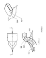
- FIG. 3 aa illustrates a tunnel component 322 forming an upper part of the material transfer chute 320
- FIG. 3 ab illustrates the dust control apparatus with the tunnel component removed for clarity.
- the tunnel component 322 extends upward and curves to form a horizontal intake for receiving material horizontally from the upper conveyor section 300
- FIG. 3 c further illustrates top, perspective and sectional views of the chute 320 including the tunnel component 322 .
- the chute 320 with tunnel component 322 forms a substantially downward curving and “S” shaped channel for guiding the material downward from the upper conveyor section 300 to the lower conveyor section 350 through the aperture 325 . This channel may be described as an S tunnel without a lower floor.
- the bulk material is driven horizontally off the upper conveyor section 300 into the channel, which contains and directs the material. Due to its shape, the channel may maintain at least some forward momentum of the bulk material, since the channel continues substantially in the same direction as the upper conveyor section. Furthermore, the channel may function to limit or even minimize turbulence or “boiling” as the material reaches the lower conveyor section 350 .
- the tunnel component 322 may optionally be replaced with a funnel or other hollow component for guiding material from the upper conveyor section 300 into the aperture 325 .
- FIG. 3 c also illustrates how material flows through the aperture 325 or centroid of the plough-shaped chute 325 .
- the lower conveyor section includes a cover which is mounted across the tops of the sidewalls and extend along at least a portion of the lower conveyor's length to form an enclosed area through which material is conveyed.
- the cover may include a pair of flexible sections 375 , 380 mounted on opposite sides of the lower conveyor and extending toward one another, and overlapping, meeting or almost meeting at a generally linear location 385 which runs parallel to the length of the lower conveyor.
- the flexible sections may be made of a natural or synthetic rubber material, for example, or other suitably flexible but also suitably stiff and/or suitably resilient material, and may be disposed in a peaked manner such that the flexible sections rest one upon the other at their meeting location.
- the flexible sections may be completely separate from each other or they may be connected to each other at locations toward at least one end of the lower conveyor section.
- flexible hinges such as spring hinges may be provided for coupling the flexible sections 375 , 380 to the conveyor sidewalls.
- the flexible sections themselves need not necessarily be made of flexible material; rather the flexibility is provided through the hinges and the flexible sections may optionally be formed of rigid material.
- the flexible sections may be formed of a number of separate panels, so that forcing apart one pair of opposed panels due to interposing of the chute does not result in forcing apart of adjacent opposed panels.
- the flexible sections may be formed of a plurality of portions of material which interlock in a hinged manner to provide the required flexibility.
- rigid sections may be rotatably interlocked with pins to provide flexibility at desired locations.
- the rigid sections may include overlapping bottom portions configured to inhibit downward flexibility past a certain angle while allowing upward flexibility when encountering the wedge of the material transfer chute.
- the dust control apparatus further comprises a material transfer chute 320 which is mounted at the transfer end of the upper conveyor section, substantially in line with an end of the belt conveyor of the upper conveyor section.
- the chute defines an internal aperture 325 through which the material flows from the upper conveyor section to the lower conveyor section.
- the outer surface of the chute comprises a pair of tapered, wedge-shaped or plough-shaped features 330 , 335 fore and aft, suitably in line with the meeting location 385 of the flexible cover sections.
- the gap is widened by one of the wedge-shaped features to accommodate the chute.
- the gap narrows with distance away from the chute.
- Such bias may be due for example to one or both of gravitational force and resilience of the flexible material.
- one plough feature functions to separate the cover sections while the other plough feature forms a graduated surface onto which the cover sections can be gradually returned toward each other after being separated.
- the dust control apparatus allows for a substantial portion of the lower conveyor section to be covered by the flexible cover sections in cooperation with each other, while also allowing for an opening to be formed at one of a continuum of locations along the lower conveyor's length for material transfer to the lower conveyor. This allows for telescoping of the conveyor while also maintaining an enclosure around the conveyor for example for facilitating dust control by mitigating egress of material from the conveyor.
- the dust control apparatus comprises one or more pressing mechanisms such as rollers 340 a and 340 b , which are configured to press the flexible cover sections together at a location away from, but typically adjacent to, the material transfer chute.
- Such pressing mechanisms may be located fore and/or aft of the material transfer chute and function to reduce the size of the opening formed between the cover sections by the chute's outer surface.
- the rollers may be mounted on pivotable arms which are biased, for example by a spring or hydraulic means, to press the cover sections 375 , 380 toward the meeting location 385 .
- FIGS. 4 aa and 4 ab illustrate the peaked manner in which the flexible sections 375 , 380 may meet, in accordance with some embodiments of the present invention.
- Optional spring hinges 377 are also shown for connecting the flexible sections to anchoring protrusion on the sidewall.
- the angle 410 between the flexible sections may be adjusted based on various factors, such as shape of the chute, resilience of the flexible section material, and the like.
- the flexible sections 375 , 380 may rest against each other.
- the material transfer chute 320 includes a wedge having a leading edge which engages and parts the flexible sections at their meeting point.
- FIG. 4 aa illustrates the chute 320 including a tunnel component 322 as previously described.
- FIG. 4 ab illustrates the chute 320 with the tunnel component removed, to better show the aperture 325 .
- the flexible sections may be angled downward, rather than upward. In other embodiments, the flexible sections may be substantially horizontal and/or parallel to each other. However, upwardly angled flexible sections may be preferable in various embodiments since they will tend to fall toward each other under the influence of gravity, thereby forming an enclosure over the conveyor.
- the flexible material may have a relatively low resilience, for example they may be more plastically deformable than elastically deformable. This may require gravity or the use of pressing mechanisms as mentioned above to close the gap between flexible sections following intrusion of the chute therebetween.
- the flexible material may have relatively high resilience, in that the material is biased to return to a neutral position following deformation. The neutral position generally may correspond to the flexible sections contacting or substantially proximate each other to close the gap therebetween.
- the flexible sections may comprise substantially straight edges which meet each other.
- the edges may be jagged or curved.
- brush material such as nylon material, may protrude outwardly from each edge, the opposing brush portions overlapping with each other to form the enclosure.
- a nominal gap may exist between the flexible sections even when they are proximate each other to form the enclosure, the gap optionally being bridged by the brush portions.
- the edges of the flexible sections 375 , 380 may comprise features such as ledges or lips 405 , 410 as illustrated in FIG. 4 b , which facilitate the resting of the flexible sections each upon the other.
- the amount of deviation of such features from a center meeting line 415 is limited, the features are substantially free of sharp corners, or both. This facilitates smooth movement of the wedged material transfer chute between the flexible sections for parting same.
- the edges 420 , 425 of the flexible sections 375 , 380 are substantially straight and parallel, as illustrated in FIG. 4 c , or non-parallel, as illustrated in FIG. 4 d .
- Other configurations and shapes of the edges of the flexible sections may also be used.
- the dust control apparatus as described above may be applied in particular for use on a telescoping conveyor, which allows for dust control to be applied at varying conveyor lengths, and mitigates dust and/or material loss due to movement of bulk material along the conveyor as well as between conveyor sections. It is, however, noted that the dust control apparatus may be incorporated into other applications.
- the cover sections may be provided to enclose a container which does not include a conveyor, and the material transfer chute may be movably interposed between the cover sections so as to deposit material in various locations within the enclosed container.
- the cover sections may be provided on a material receiving portion of a conveyor and the material transfer chute may be configured as a movable hopper which allows material to be inserted onto the conveyor at a variable location.
- a hydraulic fluid transmission system which includes at least one hollow structural element which also operates as a conduit for the hydraulic fluid.
- the structural element is formed of a material, such as metal, which is of sufficient strength to provide structural support to an associated apparatus, while also adequately containing the hydraulic fluid under pressure.
- the material is further conductive of heat, so that excess heat from the hydraulic fluid is radiated to the exterior of the structural element.
- the radiated heat may be used for a further purpose, for example to melt snow or ice off of the exterior of the structure.
- the structural element may be formed of metal, for example, with an interior channel having a substantially circular cross section.
- the hollow structural element generally forms a portion of the hydraulic fluid transmission system between the hydraulic power source and one or more hydraulically driven mechanical elements, such as pistons.
- the transmission line may convey fluid in either direction under pressure.
- the hollow structural element may be connected to other hoses or conduits of the transmission system via flexible couplings such as hoses, as would be readily understood by a worker skilled in the art.
- the hollow member may be made by an extrusion process.
- the structural element forms part of a mobile conveyor vehicle, such as an element of or supporting a telescoping conveyor section mounted on the vehicle.
- the hydraulic drive system may be used for telescoping, orienting and/or driving the conveyor, for example.
- FIGS. 5 a and 5 b illustrate a hydraulic fluid transmission system, in perspective and cross section, respectively, for a mobile conveyor vehicle 500 comprising a structural frame 510 and a source of hydraulic fluid 515 .
- the hydraulic fluid transmission system comprises at least one hollow metallic member 520 forming a structural element of a structural frame. In the illustrated case, the member 520 extends along a length of the conveyor section and includes an interior aperture 512 for conveying fluid along its length.
- the hollow metallic member 520 is operatively coupled to the source of hydraulic fluid 515 and operates as a transmission line.
- the hollow metallic member 520 is further configured to radiate excess heat from the hydraulic fluid outward for heating the vehicle structure and potentially facilitating melting of snow or ice on the structure.
- a plurality of such hollow metallic members, including 520 as well as 540 , 542 , 544 may be provided, for example one at each corner of the conveyor section. Hot oil from a hydraulic motor 517 may be returned through the upper members 520 , 542 and pressurized oil to the hydraulic motor may be routed through the lower members 540 , 544 .
- the particular mobile conveyor vehicle, dust control apparatus and hydraulic fluid transmission system as described herein may be provided together or separately in accordance with different embodiments of the invention.
- one or both of the dust control apparatus and the hydraulic fluid transmission system may be incorporated into other systems, such as other types of mobile conveyor vehicles or other work vehicles.
- FIG. 6 illustrates a system comprising a mobile conveyor vehicle 610 as described herein, receiving bulk material from a delivery truck 620 and conveying the material to one of a plurality of elevated storage containers 630 .
- the system may be mobile and set up for substantially temporary use in a remote location, such as a hydraulic fracturing site.
- the delivery truck 620 may be located at a delivery point located along a suitably placed vehicle-accessible road or path 625 .
- the storage containers 630 may be arranged for example along a line adjacent to a conveyor 640 which receives material from the storage containers as needed for example to facilitate hydraulic fracturing operations.
- the system may integrate various components of a SandStormTM material handling system provided by TyCropTM, for example with the storage containers 630 corresponding to GravityBoxTM containers as also provided by TyCropTM.
- the storage containers may include multiple hatches for receiving material at different locations.
- the conveyor vehicle may be configured to position the endpoints 652 , 662 of its infeed conveyor 650 and output conveyor 660 , respectively, so as to receive material from an output hatch of the delivery truck 620 and deliver it to a selected one of the storage containers 630 .
- Positioning the conveyor endpoints 652 , 662 may comprise rotating the conveyors, telescoping the conveyors, elevating or lowering the conveyors, and optionally moving the vehicle itself from one location to another.
- the vehicle 610 may be placed at an alternate location on the opposite side of the line of storage containers.
- the output conveyor endpoint 662 may be capable of traversing roughly in an arc and of extending such that it can discharge into a selected one of the storage containers 630 , preferably without relocation of the vehicle or containers.
- the output conveyor is extendable by about 46 feet and capable of elevation of up to about 56 feet.
- the output conveyor endpoint 662 may also be capable of discharging at extended minimum and maximum reach into low elevation devices such as industrial sand conveyors, blenders, bulk tankers, and ground-level stockpiles, and the like. Discharging into bulk tankers may be desirable for material removal on job completion.
- the mobile conveyor vehicle is controlled by a remote control system, comprising radio communication components, sensor and actuator components, transducers, and the like.
Abstract
Description
Claims (10)
Priority Applications (3)
| Application Number | Priority Date | Filing Date | Title |
|---|---|---|---|
| US14/286,488 US9499348B2 (en) | 2014-05-23 | 2014-05-23 | Material handling conveyor vehicle |
| CA2852719A CA2852719C (en) | 2014-05-23 | 2014-05-27 | Material handling conveyor vehicle |
| US14/945,944 US9334124B2 (en) | 2014-05-23 | 2015-11-19 | Material handling conveyor vehicle |
Applications Claiming Priority (1)
| Application Number | Priority Date | Filing Date | Title |
|---|---|---|---|
| US14/286,488 US9499348B2 (en) | 2014-05-23 | 2014-05-23 | Material handling conveyor vehicle |
Related Child Applications (1)
| Application Number | Title | Priority Date | Filing Date |
|---|---|---|---|
| US14/945,944 Division US9334124B2 (en) | 2014-05-23 | 2015-11-19 | Material handling conveyor vehicle |
Publications (2)
| Publication Number | Publication Date |
|---|---|
| US20150336747A1 US20150336747A1 (en) | 2015-11-26 |
| US9499348B2 true US9499348B2 (en) | 2016-11-22 |
Family
ID=54555527
Family Applications (2)
| Application Number | Title | Priority Date | Filing Date |
|---|---|---|---|
| US14/286,488 Active 2034-06-18 US9499348B2 (en) | 2014-05-23 | 2014-05-23 | Material handling conveyor vehicle |
| US14/945,944 Active US9334124B2 (en) | 2014-05-23 | 2015-11-19 | Material handling conveyor vehicle |
Family Applications After (1)
| Application Number | Title | Priority Date | Filing Date |
|---|---|---|---|
| US14/945,944 Active US9334124B2 (en) | 2014-05-23 | 2015-11-19 | Material handling conveyor vehicle |
Country Status (2)
| Country | Link |
|---|---|
| US (2) | US9499348B2 (en) |
| CA (1) | CA2852719C (en) |
Cited By (12)
| Publication number | Priority date | Publication date | Assignee | Title |
|---|---|---|---|---|
| US9957108B2 (en) | 2015-06-08 | 2018-05-01 | Continental Intermodal Group-Trucking Llc | Conveyor transition for material handling |
| US20180333987A1 (en) * | 2017-05-19 | 2018-11-22 | J.C. Bamford Excavators Limited | Working Machine |
| US20180362259A1 (en) * | 2017-06-19 | 2018-12-20 | Brandt Industries Canada Limited | Manually steered auger mover |
| US20190039430A1 (en) * | 2017-08-02 | 2019-02-07 | Gary Crook | Vehicle wheel positioning and steering apparatus |
| US10315850B2 (en) * | 2017-07-13 | 2019-06-11 | 1875452 Alberta Ltd. | Proppant conveyor systems and methods of use |
| US10399785B1 (en) | 2018-05-31 | 2019-09-03 | Stout Conveyors, LLC | Compact portable conveyor |
| US10518982B1 (en) * | 2019-06-14 | 2019-12-31 | Stout Conveyors, LLC | Feed conveyor for compact portable conveyor |
| US10625959B2 (en) | 2018-02-27 | 2020-04-21 | Todd A. Larson | Dust control device |
| US20210354910A1 (en) * | 2018-09-14 | 2021-11-18 | National Oilwell Varco, L.P. | Proppant supply system |
| US11267663B2 (en) * | 2019-01-15 | 2022-03-08 | Quickthree Technology, Llc | Bottom dump pneumatic material handling system |
| US11691831B2 (en) | 2019-01-22 | 2023-07-04 | 543077 Alberta Ltd. | Portable conveyor system including pivotable and extendable feed conveyors for feeding particulate material into an elevating assembly |
| US11880804B1 (en) | 2020-04-29 | 2024-01-23 | Prop Sense Canada Ltd. | System and method for automated inventory, transport, management, and storage control in hydraulic fracturing operations |
Families Citing this family (21)
| Publication number | Priority date | Publication date | Assignee | Title |
|---|---|---|---|---|
| US9428348B2 (en) | 2010-10-21 | 2016-08-30 | Ty-Crop Manufacturing Ltd. | Mobile material handling and metering system |
| CA2893686A1 (en) | 2014-06-09 | 2015-12-09 | Ty-Crop Manufacturing Ltd. | Control system for material handling conveyor vehicle |
| CA168558S (en) * | 2016-05-19 | 2017-05-01 | Brandt Ind Ltd | Conveyor |
| CN107487598A (en) * | 2016-11-15 | 2017-12-19 | 中煤第五建设有限公司 | A kind of concrete material discharging of roadway construction, feeding system |
| US10470373B2 (en) * | 2017-03-22 | 2019-11-12 | Cnh Industrial America Llc | Agricultural vehicle with belt unloader |
| CA3005521A1 (en) * | 2017-05-22 | 2018-11-22 | Vermeer Manufacturing Company | Pivoting conveyor |
| CN107265144A (en) * | 2017-06-27 | 2017-10-20 | 江苏绿叶机械有限公司 | A kind of cement bulk dust arrester installation |
| PL234330B1 (en) * | 2017-07-18 | 2020-02-28 | Kobzarenko Spolka Z Ograniczona Odpowiedzialnoscia | Unloading device |
| US10543990B2 (en) | 2017-11-21 | 2020-01-28 | Ag Automation, Inc. | Automatic front and rear lift self-propelled agricultural conveyor |
| CN108890247B (en) * | 2018-07-27 | 2023-08-11 | 无锡丹尼克尔自动化科技有限公司 | Quantitative feeding device |
| US11506314B2 (en) | 2018-12-10 | 2022-11-22 | National Oilwell Varco Uk Limited | Articulating flow line connector |
| CN110143448A (en) * | 2019-06-25 | 2019-08-20 | 四川省星船城水泥股份有限公司 | A kind of stacker-reclaimer of good dustproof effect |
| US11828150B2 (en) | 2019-07-01 | 2023-11-28 | National Oilwell Varco, L.P. | Smart manifold |
| CN110171716B (en) * | 2019-07-04 | 2023-11-24 | 山东煜龙环保科技股份有限公司 | Bulk material conveyer |
| CN111717590A (en) * | 2020-06-22 | 2020-09-29 | 惠安县崇武镇婉云广告设计中心 | Convenient transfer device of material for interior decoration |
| CN112193546B (en) * | 2020-09-25 | 2022-04-01 | 济南市莱芜盛腾包装科技有限公司 | Film seals cuts packagine machine |
| US11702916B2 (en) | 2020-12-22 | 2023-07-18 | National Oilwell Varco, L.P. | Controlling the flow of fluid to high pressure pumps |
| CN112660759A (en) * | 2021-01-29 | 2021-04-16 | 洛阳耐锐机械设备有限公司 | Conveying device for transferring gravel aggregate |
| CN113321004B (en) * | 2021-07-06 | 2022-03-25 | 中铁五局集团第一工程有限责任公司 | Tunnel waste slag treatment method |
| CN114455335A (en) * | 2021-08-27 | 2022-05-10 | 西门子工业自动化产品(成都)有限公司 | Separating device and method for stacked boxes |
| CN113895898B (en) * | 2021-10-08 | 2023-07-18 | 巢湖学院 | Micro-transport unit for flexible transport system and flexible transport system using the same |
Citations (102)
| Publication number | Priority date | Publication date | Assignee | Title |
|---|---|---|---|---|
| US1346990A (en) | 1919-08-15 | 1920-07-20 | Stuart Francis Lee | Conveying apparatus |
| US2124687A (en) | 1938-02-03 | 1938-07-26 | American Hard Rubber Co | Comb |
| US3086465A (en) | 1960-05-09 | 1963-04-23 | Montfort Gerald Simon De | Oil well fire control vehicle |
| US3095097A (en) | 1960-06-13 | 1963-06-25 | Paul A Mellow | Grain elevator control system |
| US3231066A (en) | 1964-05-06 | 1966-01-25 | Prospect Mfg Co Inc | Tilting conveyor apparatus |
| US3265232A (en) | 1964-11-12 | 1966-08-09 | Lythgoe Frank | Material handling devices |
| US3285439A (en) | 1961-12-20 | 1966-11-15 | Carves Simon Ltd | Coke oven wharves |
| US3310161A (en) | 1965-03-31 | 1967-03-21 | Goodyear Tire & Rubber | Turn conveyor |
| US3314557A (en) | 1965-04-16 | 1967-04-18 | Sr Walter J Sackett | Tank type bulk blending plant |
| US3501193A (en) | 1968-02-07 | 1970-03-17 | States Steamship Co | System for engaging cargo containers |
| US3530832A (en) | 1968-04-03 | 1970-09-29 | Mag Eng Inc De | Apparatus for use in removing manure from buildings having manure collecting channels |
| US3567048A (en) | 1969-10-10 | 1971-03-02 | Latham E Whitham | Remote automatic tripper operation and control by low bin determination |
| US3653486A (en) | 1970-07-17 | 1972-04-04 | Dravo Corp | Material handling apparatus |
| US3669245A (en) | 1970-01-13 | 1972-06-13 | Aerojet General Co | Tilt type conveyors |
| US3753506A (en) | 1972-05-03 | 1973-08-21 | Bell & Howell Co | Unitized refuse transfer station |
| US3884346A (en) | 1972-06-22 | 1975-05-20 | Powerscreen Int Ltd | Conveyor unit |
| US3899037A (en) * | 1973-07-16 | 1975-08-12 | Paul A Yuker | Chassis apparatus for all terrain vehicles |
| US3934739A (en) | 1974-02-13 | 1976-01-27 | Standard Havens, Inc. | Self-erecting surge storage system |
| US4101019A (en) | 1973-11-07 | 1978-07-18 | Satterwhite Charles R | Aerial conveyor system |
| US4187047A (en) | 1978-03-09 | 1980-02-05 | Boeing Construction Equipment Company | System and apparatus for erecting a portable silo and elevator structure |
| US4198186A (en) | 1977-06-24 | 1980-04-15 | Holdren Brothers, Inc. | Silo dig out tool |
| US4268208A (en) | 1979-12-13 | 1981-05-19 | Cmi Corporation | Portable self-erecting silo apparatus |
| US4319677A (en) | 1980-09-29 | 1982-03-16 | Phb-Weserhutte Ag | Stockyard transporter and tripper car equipment |
| US4330232A (en) | 1978-07-03 | 1982-05-18 | Mcclaren Jay L | Grain bin and truck loading and unloading system |
| US4337014A (en) | 1980-11-28 | 1982-06-29 | Barber-Greene Company | Method and apparatus for erecting a portable silo and elevator |
| US4345869A (en) | 1980-11-03 | 1982-08-24 | King John L | Conveyor system for loading and unloading trucks and trailers |
| US4387798A (en) | 1977-06-24 | 1983-06-14 | Consolidation Coal Company | Cascading conveyor system |
| US4392776A (en) | 1981-05-15 | 1983-07-12 | Westinghouse Electric Corp. | Robotic manipulator structure |
| US4465420A (en) | 1982-03-03 | 1984-08-14 | Bituma-Stor, Inc. | Self-erecting portable paving mix silo |
| US4482281A (en) | 1982-12-01 | 1984-11-13 | Iowa Manufacturing Company Of Cedar | Portable asphalt storage silo |
| US4491216A (en) | 1982-07-19 | 1985-01-01 | Sawby Kenneth J | Grain handling system |
| US4561821A (en) | 1984-12-20 | 1985-12-31 | Bituma-Stor, Inc. | Portable self-erecting surge storage silo |
| US4568239A (en) | 1978-08-07 | 1986-02-04 | Sims Royal W | Hydraulically operated batch-loader for dry mix concrete |
| US4624357A (en) * | 1984-06-25 | 1986-11-25 | Rotec Industries, Inc. | Vehicle-mounted extensible conveyor |
| US4629060A (en) | 1984-08-14 | 1986-12-16 | Schlegel Hans J | Apparatus for handling bulk material |
| US4701095A (en) | 1984-12-28 | 1987-10-20 | Halliburton Company | Transportable material conveying apparatus |
| US4813526A (en) * | 1986-11-03 | 1989-03-21 | Entrepreises Premier Cdn Ltee. | Conveyor |
| GB2222995A (en) | 1988-09-09 | 1990-03-28 | Hausherr Limited | Mobile conveyors |
| US4917560A (en) | 1989-01-19 | 1990-04-17 | Cmi Corporation | Twin bin self erect silo |
| US4924993A (en) | 1988-06-08 | 1990-05-15 | Buxton Robert W | Conveyor assembly |
| US4944646A (en) | 1989-01-12 | 1990-07-31 | Astec Industries, Inc. | Highway transportable material storage apparatus and frame assembly therefor |
| US5087155A (en) | 1990-04-25 | 1992-02-11 | Blowhard Pneumatic Services Inc. | Apparatus for introducing bulk materials into pneumatic conveying line |
| US5125771A (en) | 1990-04-25 | 1992-06-30 | Blowhard Pneumatic Services, Inc. | Apparatus for introducing bulk materials into pneumatic conveying line |
| US5129508A (en) | 1991-03-25 | 1992-07-14 | Keith Shelstad | Dust control system |
| US5141528A (en) | 1991-03-27 | 1992-08-25 | Super Products Corporation | Separator docking system |
| US5203442A (en) * | 1991-04-29 | 1993-04-20 | Rotec Industries, Inc. | Cantilever conveying techniques |
| US5203628A (en) | 1988-09-30 | 1993-04-20 | Hamm Family Partnership | Portable batch mixing apparatus for cementitious construction materials |
| US5297665A (en) | 1993-03-29 | 1994-03-29 | Smith Roger G | Vehicle with multiple serving conveyors |
| DE4235276A1 (en) | 1992-10-20 | 1994-04-21 | Melchior Maschbau Gmbh | Small silo for bulk building materials |
| US5339996A (en) | 1993-04-26 | 1994-08-23 | Midwest Pre-Mix, Inc. | Portable mini silo system |
| US5340259A (en) | 1992-11-24 | 1994-08-23 | Flaskey David L | Round bale handling trailer apparatus |
| US5427497A (en) | 1993-10-15 | 1995-06-27 | Dillman; Bruce A. | Horizontal surge/storage silo |
| US5431523A (en) | 1993-01-04 | 1995-07-11 | Ferguson Farms, Inc. | Remote control for a reciprocating vehicle bed conveyor floor |
| US5577618A (en) | 1993-09-07 | 1996-11-26 | Rafferty; Malachy J. | Mobile aggregate material processing plant |
| US5634716A (en) | 1995-10-30 | 1997-06-03 | Coronado Engineering, Inc. | Portable batch blending system |
| US5640996A (en) | 1993-02-27 | 1997-06-24 | Putzmeister-Werk Maschinenfabrik Gmbh | Large manipulator, especially for self-propelled concrete pumps |
| US5865300A (en) | 1996-10-04 | 1999-02-02 | Newsome; John R. | Presser assembly for turning conveyors |
| WO1999050091A1 (en) | 1998-04-01 | 1999-10-07 | Putzmeister Ag | Travelling conveyor |
| US6135171A (en) | 1999-03-18 | 2000-10-24 | Weakly; L. Alan | Passive enclosure dust control system |
| US6186311B1 (en) | 1998-11-25 | 2001-02-13 | Ohio Machinery Co. | Self-transporting multiple conveyor system |
| US6186654B1 (en) | 1999-02-23 | 2001-02-13 | Guntert & Zimmerman Construction Division, Inc. | Portable and modular batching and mixing plant for concrete and the like |
| US6283269B1 (en) * | 1999-12-03 | 2001-09-04 | Putzmeister, Inc. | Vehicle-mounted extendable conveyor having variable angle infeed conveyor assembly |
| US6293689B1 (en) | 2000-09-20 | 2001-09-25 | Guntert & Zimmerman Const. Div., Inc. | High volume portable concrete batching and mixing plant having compulsory mixer with overlying supported silo |
| US6360876B1 (en) | 1994-08-11 | 2002-03-26 | Superior Industries, Inc. | Portable telescoping radial stacking conveyor |
| US6367610B1 (en) | 2000-02-14 | 2002-04-09 | Mantissa Corporation | High efficiency sorting conveyor |
| US6378686B1 (en) * | 1999-06-02 | 2002-04-30 | Putzmeister Inc. | Vehicle-mounted conveyor system including powered rotating infeed conveyor |
| US6386352B1 (en) * | 2001-04-30 | 2002-05-14 | Blaw-Knox Construction Equipment Corporation | Swing conveyor assembly |
| US6527428B2 (en) | 2000-09-20 | 2003-03-04 | Guntert & Zimmerman Const. Div., Inc. | High volume portable concrete batching and mixing plant having compulsory mixer with overlying supported silo |
| US6540039B1 (en) * | 1999-08-19 | 2003-04-01 | Massachusetts Institute Of Technology | Omnidirectional vehicle with offset wheel pairs |
| US6543622B1 (en) | 2001-03-27 | 2003-04-08 | Terex Corporation | Portable conveyor with swivel and fold |
| US6688450B2 (en) * | 2001-04-30 | 2004-02-10 | Blaw-Knox Construction Equipment Corporation | Mobile conveyor for paving vehicles |
| US6810976B2 (en) * | 2002-04-23 | 2004-11-02 | Massachusetts Institute Of Technology | Omni-directional, holonomic drive mechanism |
| US6827198B1 (en) | 2001-01-09 | 2004-12-07 | Laitram, L.L.C. | Tilt conveyor |
| US6866071B2 (en) | 2003-02-07 | 2005-03-15 | Air Control Science, Inc. | Dustless Stacker method and apparatus for a bulk solids handling and storage system |
| US6910586B2 (en) | 2003-03-19 | 2005-06-28 | Mccloskey James Paschal | System and method for folding conveyors |
| US6929113B1 (en) | 2004-03-17 | 2005-08-16 | Hoover Conveyor & Fabrication Corp. | Telescoping stacking conveyor having a single conveyor belt and single drive mechanism for the belt |
| US6986294B2 (en) | 2000-02-17 | 2006-01-17 | Bintech Lllp | Bulk materials management apparatus and method |
| US7150352B2 (en) | 2002-04-12 | 2006-12-19 | Dematic Corp. | Curved belt conveyor |
| US20070029170A1 (en) | 2005-08-03 | 2007-02-08 | Superior Industries, Llc | Rolling conveyor support |
| US7198278B2 (en) * | 2004-03-24 | 2007-04-03 | Genie Industries, Inc. | Vehicle support system |
| US7223059B2 (en) | 2004-10-22 | 2007-05-29 | Construction Equipment Company | Adjustable conveyor system |
| US7255194B2 (en) * | 2004-12-21 | 2007-08-14 | Daimlerchrysler Corporation | Steering system for a zero-steer vehicle |
| US20070193798A1 (en) | 2005-10-21 | 2007-08-23 | James Allard | Systems and methods for obstacle avoidance |
| US20080008562A1 (en) | 2006-07-07 | 2008-01-10 | Jeff Beckel | Method of transporting and storing an oilfield proppant |
| US20080179054A1 (en) | 2007-01-30 | 2008-07-31 | Halliburton Energy Services, Inc. | Methods for expandable storage and metering |
| US20090078410A1 (en) | 2007-09-21 | 2009-03-26 | David Krenek | Aggregate Delivery Unit |
| US7789217B2 (en) | 2007-12-12 | 2010-09-07 | Ccc Group, Inc. | Dust control material transfer system |
| US7887110B2 (en) | 2008-04-29 | 2011-02-15 | Fooyin University | Automatic detaching structure for a hook device |
| US7946416B2 (en) | 2008-10-31 | 2011-05-24 | Rodono Industries Ltd. | Retractable transfer conveyor |
| US8025140B2 (en) * | 2005-12-09 | 2011-09-27 | Metso Minerals Inc. | Material processing apparatus comprising a conveyor |
| US8033376B2 (en) * | 2007-12-10 | 2011-10-11 | Bernie John Toews | Steerable conveyor |
| US8251199B2 (en) | 2009-12-03 | 2012-08-28 | Flsmidth A/S | Conveyor apparatus |
| US20120219391A1 (en) | 2010-10-21 | 2012-08-30 | Ty-Crop Manufacturing Ltd. | Mobile Material Handling and Metering System |
| US8322507B2 (en) | 2007-02-08 | 2012-12-04 | Prairie Machine & Parts Mfg. (1978) Ltd. | Conveyor machine having pivot connector comprising curved track and rollers engaging track |
| US8408377B2 (en) | 2008-03-05 | 2013-04-02 | Earth Corp. Industries, Llc | Reload conveyor with articulating conveyor frame |
| US20130118862A1 (en) | 2011-11-15 | 2013-05-16 | All-Right Steel LLC | Pivoting Conveyor System |
| US20140023467A1 (en) | 2009-04-20 | 2014-01-23 | Volvo Construction Equipment Ab | Integrated paving system and method |
| US8640855B2 (en) | 2010-10-13 | 2014-02-04 | Steven Hays Brobst | Apparatus and method for passive dust control in a transfer chute |
| US8944740B2 (en) | 2010-10-21 | 2015-02-03 | Ty-Crop Manufacturing Ltd. | Mobile material handling and metering system |
| US8944239B2 (en) * | 2010-10-26 | 2015-02-03 | Engineered Lifting Systems & Equipment Inc. | Conveyor apparatus for loading or unloading packages from shipping containers |
| US20150044004A1 (en) | 2013-08-08 | 2015-02-12 | Schlumberger Technology Corporation | Mobile oilfield materialtransfer unit |
| US9079470B2 (en) * | 2013-10-14 | 2015-07-14 | Agco Corporation | Vehicle with chassis height adjustment |
-
2014
- 2014-05-23 US US14/286,488 patent/US9499348B2/en active Active
- 2014-05-27 CA CA2852719A patent/CA2852719C/en active Active
-
2015
- 2015-11-19 US US14/945,944 patent/US9334124B2/en active Active
Patent Citations (105)
| Publication number | Priority date | Publication date | Assignee | Title |
|---|---|---|---|---|
| US1346990A (en) | 1919-08-15 | 1920-07-20 | Stuart Francis Lee | Conveying apparatus |
| US2124687A (en) | 1938-02-03 | 1938-07-26 | American Hard Rubber Co | Comb |
| US3086465A (en) | 1960-05-09 | 1963-04-23 | Montfort Gerald Simon De | Oil well fire control vehicle |
| US3095097A (en) | 1960-06-13 | 1963-06-25 | Paul A Mellow | Grain elevator control system |
| US3285439A (en) | 1961-12-20 | 1966-11-15 | Carves Simon Ltd | Coke oven wharves |
| US3231066A (en) | 1964-05-06 | 1966-01-25 | Prospect Mfg Co Inc | Tilting conveyor apparatus |
| US3265232A (en) | 1964-11-12 | 1966-08-09 | Lythgoe Frank | Material handling devices |
| US3310161A (en) | 1965-03-31 | 1967-03-21 | Goodyear Tire & Rubber | Turn conveyor |
| US3314557A (en) | 1965-04-16 | 1967-04-18 | Sr Walter J Sackett | Tank type bulk blending plant |
| US3501193A (en) | 1968-02-07 | 1970-03-17 | States Steamship Co | System for engaging cargo containers |
| US3530832A (en) | 1968-04-03 | 1970-09-29 | Mag Eng Inc De | Apparatus for use in removing manure from buildings having manure collecting channels |
| US3567048A (en) | 1969-10-10 | 1971-03-02 | Latham E Whitham | Remote automatic tripper operation and control by low bin determination |
| US3669245A (en) | 1970-01-13 | 1972-06-13 | Aerojet General Co | Tilt type conveyors |
| US3653486A (en) | 1970-07-17 | 1972-04-04 | Dravo Corp | Material handling apparatus |
| US3753506A (en) | 1972-05-03 | 1973-08-21 | Bell & Howell Co | Unitized refuse transfer station |
| US3884346A (en) | 1972-06-22 | 1975-05-20 | Powerscreen Int Ltd | Conveyor unit |
| US3899037A (en) * | 1973-07-16 | 1975-08-12 | Paul A Yuker | Chassis apparatus for all terrain vehicles |
| US4101019A (en) | 1973-11-07 | 1978-07-18 | Satterwhite Charles R | Aerial conveyor system |
| US3934739A (en) | 1974-02-13 | 1976-01-27 | Standard Havens, Inc. | Self-erecting surge storage system |
| US4198186A (en) | 1977-06-24 | 1980-04-15 | Holdren Brothers, Inc. | Silo dig out tool |
| US4387798A (en) | 1977-06-24 | 1983-06-14 | Consolidation Coal Company | Cascading conveyor system |
| US4187047A (en) | 1978-03-09 | 1980-02-05 | Boeing Construction Equipment Company | System and apparatus for erecting a portable silo and elevator structure |
| US4330232A (en) | 1978-07-03 | 1982-05-18 | Mcclaren Jay L | Grain bin and truck loading and unloading system |
| US4568239A (en) | 1978-08-07 | 1986-02-04 | Sims Royal W | Hydraulically operated batch-loader for dry mix concrete |
| US4268208A (en) | 1979-12-13 | 1981-05-19 | Cmi Corporation | Portable self-erecting silo apparatus |
| US4319677A (en) | 1980-09-29 | 1982-03-16 | Phb-Weserhutte Ag | Stockyard transporter and tripper car equipment |
| US4345869A (en) | 1980-11-03 | 1982-08-24 | King John L | Conveyor system for loading and unloading trucks and trailers |
| US4337014A (en) | 1980-11-28 | 1982-06-29 | Barber-Greene Company | Method and apparatus for erecting a portable silo and elevator |
| US4392776A (en) | 1981-05-15 | 1983-07-12 | Westinghouse Electric Corp. | Robotic manipulator structure |
| US4465420A (en) | 1982-03-03 | 1984-08-14 | Bituma-Stor, Inc. | Self-erecting portable paving mix silo |
| US4491216A (en) | 1982-07-19 | 1985-01-01 | Sawby Kenneth J | Grain handling system |
| US4482281A (en) | 1982-12-01 | 1984-11-13 | Iowa Manufacturing Company Of Cedar | Portable asphalt storage silo |
| US4624357A (en) * | 1984-06-25 | 1986-11-25 | Rotec Industries, Inc. | Vehicle-mounted extensible conveyor |
| US4629060A (en) | 1984-08-14 | 1986-12-16 | Schlegel Hans J | Apparatus for handling bulk material |
| US4561821A (en) | 1984-12-20 | 1985-12-31 | Bituma-Stor, Inc. | Portable self-erecting surge storage silo |
| US4701095A (en) | 1984-12-28 | 1987-10-20 | Halliburton Company | Transportable material conveying apparatus |
| US4813526A (en) * | 1986-11-03 | 1989-03-21 | Entrepreises Premier Cdn Ltee. | Conveyor |
| US4924993A (en) | 1988-06-08 | 1990-05-15 | Buxton Robert W | Conveyor assembly |
| GB2222995A (en) | 1988-09-09 | 1990-03-28 | Hausherr Limited | Mobile conveyors |
| US5277489A (en) | 1988-09-30 | 1994-01-11 | Hamm Family Partnership | Portable batch mixing apparatus for cementitious construction materials |
| US5203628A (en) | 1988-09-30 | 1993-04-20 | Hamm Family Partnership | Portable batch mixing apparatus for cementitious construction materials |
| US4944646A (en) | 1989-01-12 | 1990-07-31 | Astec Industries, Inc. | Highway transportable material storage apparatus and frame assembly therefor |
| US4917560A (en) | 1989-01-19 | 1990-04-17 | Cmi Corporation | Twin bin self erect silo |
| US5125771A (en) | 1990-04-25 | 1992-06-30 | Blowhard Pneumatic Services, Inc. | Apparatus for introducing bulk materials into pneumatic conveying line |
| US5087155A (en) | 1990-04-25 | 1992-02-11 | Blowhard Pneumatic Services Inc. | Apparatus for introducing bulk materials into pneumatic conveying line |
| US5129508A (en) | 1991-03-25 | 1992-07-14 | Keith Shelstad | Dust control system |
| US5141528A (en) | 1991-03-27 | 1992-08-25 | Super Products Corporation | Separator docking system |
| US5203442A (en) * | 1991-04-29 | 1993-04-20 | Rotec Industries, Inc. | Cantilever conveying techniques |
| DE4235276A1 (en) | 1992-10-20 | 1994-04-21 | Melchior Maschbau Gmbh | Small silo for bulk building materials |
| US5340259A (en) | 1992-11-24 | 1994-08-23 | Flaskey David L | Round bale handling trailer apparatus |
| US5431523A (en) | 1993-01-04 | 1995-07-11 | Ferguson Farms, Inc. | Remote control for a reciprocating vehicle bed conveyor floor |
| US5640996A (en) | 1993-02-27 | 1997-06-24 | Putzmeister-Werk Maschinenfabrik Gmbh | Large manipulator, especially for self-propelled concrete pumps |
| US5297665A (en) | 1993-03-29 | 1994-03-29 | Smith Roger G | Vehicle with multiple serving conveyors |
| US5339996A (en) | 1993-04-26 | 1994-08-23 | Midwest Pre-Mix, Inc. | Portable mini silo system |
| US5577618A (en) | 1993-09-07 | 1996-11-26 | Rafferty; Malachy J. | Mobile aggregate material processing plant |
| US5427497A (en) | 1993-10-15 | 1995-06-27 | Dillman; Bruce A. | Horizontal surge/storage silo |
| US6360876B1 (en) | 1994-08-11 | 2002-03-26 | Superior Industries, Inc. | Portable telescoping radial stacking conveyor |
| US5634716A (en) | 1995-10-30 | 1997-06-03 | Coronado Engineering, Inc. | Portable batch blending system |
| US5865300A (en) | 1996-10-04 | 1999-02-02 | Newsome; John R. | Presser assembly for turning conveyors |
| WO1999050091A1 (en) | 1998-04-01 | 1999-10-07 | Putzmeister Ag | Travelling conveyor |
| US6186311B1 (en) | 1998-11-25 | 2001-02-13 | Ohio Machinery Co. | Self-transporting multiple conveyor system |
| US6186654B1 (en) | 1999-02-23 | 2001-02-13 | Guntert & Zimmerman Construction Division, Inc. | Portable and modular batching and mixing plant for concrete and the like |
| US6135171A (en) | 1999-03-18 | 2000-10-24 | Weakly; L. Alan | Passive enclosure dust control system |
| US6378686B1 (en) * | 1999-06-02 | 2002-04-30 | Putzmeister Inc. | Vehicle-mounted conveyor system including powered rotating infeed conveyor |
| US6540039B1 (en) * | 1999-08-19 | 2003-04-01 | Massachusetts Institute Of Technology | Omnidirectional vehicle with offset wheel pairs |
| US6283269B1 (en) * | 1999-12-03 | 2001-09-04 | Putzmeister, Inc. | Vehicle-mounted extendable conveyor having variable angle infeed conveyor assembly |
| US6367610B1 (en) | 2000-02-14 | 2002-04-09 | Mantissa Corporation | High efficiency sorting conveyor |
| US6986294B2 (en) | 2000-02-17 | 2006-01-17 | Bintech Lllp | Bulk materials management apparatus and method |
| US6293689B1 (en) | 2000-09-20 | 2001-09-25 | Guntert & Zimmerman Const. Div., Inc. | High volume portable concrete batching and mixing plant having compulsory mixer with overlying supported silo |
| US6527428B2 (en) | 2000-09-20 | 2003-03-04 | Guntert & Zimmerman Const. Div., Inc. | High volume portable concrete batching and mixing plant having compulsory mixer with overlying supported silo |
| US6827198B1 (en) | 2001-01-09 | 2004-12-07 | Laitram, L.L.C. | Tilt conveyor |
| US6543622B1 (en) | 2001-03-27 | 2003-04-08 | Terex Corporation | Portable conveyor with swivel and fold |
| US6386352B1 (en) * | 2001-04-30 | 2002-05-14 | Blaw-Knox Construction Equipment Corporation | Swing conveyor assembly |
| US6688450B2 (en) * | 2001-04-30 | 2004-02-10 | Blaw-Knox Construction Equipment Corporation | Mobile conveyor for paving vehicles |
| US7150352B2 (en) | 2002-04-12 | 2006-12-19 | Dematic Corp. | Curved belt conveyor |
| US6810976B2 (en) * | 2002-04-23 | 2004-11-02 | Massachusetts Institute Of Technology | Omni-directional, holonomic drive mechanism |
| US6866071B2 (en) | 2003-02-07 | 2005-03-15 | Air Control Science, Inc. | Dustless Stacker method and apparatus for a bulk solids handling and storage system |
| US6910586B2 (en) | 2003-03-19 | 2005-06-28 | Mccloskey James Paschal | System and method for folding conveyors |
| US6929113B1 (en) | 2004-03-17 | 2005-08-16 | Hoover Conveyor & Fabrication Corp. | Telescoping stacking conveyor having a single conveyor belt and single drive mechanism for the belt |
| US7198278B2 (en) * | 2004-03-24 | 2007-04-03 | Genie Industries, Inc. | Vehicle support system |
| US7296676B2 (en) | 2004-10-22 | 2007-11-20 | Construction Equipment Company | Adjustable conveyor system |
| US7223059B2 (en) | 2004-10-22 | 2007-05-29 | Construction Equipment Company | Adjustable conveyor system |
| US7255194B2 (en) * | 2004-12-21 | 2007-08-14 | Daimlerchrysler Corporation | Steering system for a zero-steer vehicle |
| US20070029170A1 (en) | 2005-08-03 | 2007-02-08 | Superior Industries, Llc | Rolling conveyor support |
| US20070193798A1 (en) | 2005-10-21 | 2007-08-23 | James Allard | Systems and methods for obstacle avoidance |
| US8025140B2 (en) * | 2005-12-09 | 2011-09-27 | Metso Minerals Inc. | Material processing apparatus comprising a conveyor |
| US20080008562A1 (en) | 2006-07-07 | 2008-01-10 | Jeff Beckel | Method of transporting and storing an oilfield proppant |
| US20080179054A1 (en) | 2007-01-30 | 2008-07-31 | Halliburton Energy Services, Inc. | Methods for expandable storage and metering |
| US8322507B2 (en) | 2007-02-08 | 2012-12-04 | Prairie Machine & Parts Mfg. (1978) Ltd. | Conveyor machine having pivot connector comprising curved track and rollers engaging track |
| US20090078410A1 (en) | 2007-09-21 | 2009-03-26 | David Krenek | Aggregate Delivery Unit |
| US8033376B2 (en) * | 2007-12-10 | 2011-10-11 | Bernie John Toews | Steerable conveyor |
| US7789217B2 (en) | 2007-12-12 | 2010-09-07 | Ccc Group, Inc. | Dust control material transfer system |
| US8408377B2 (en) | 2008-03-05 | 2013-04-02 | Earth Corp. Industries, Llc | Reload conveyor with articulating conveyor frame |
| US7887110B2 (en) | 2008-04-29 | 2011-02-15 | Fooyin University | Automatic detaching structure for a hook device |
| US7946416B2 (en) | 2008-10-31 | 2011-05-24 | Rodono Industries Ltd. | Retractable transfer conveyor |
| US20140023467A1 (en) | 2009-04-20 | 2014-01-23 | Volvo Construction Equipment Ab | Integrated paving system and method |
| US8251199B2 (en) | 2009-12-03 | 2012-08-28 | Flsmidth A/S | Conveyor apparatus |
| US8348044B2 (en) | 2009-12-03 | 2013-01-08 | Flsmidth A/S | Conveyor apparatus |
| US8640855B2 (en) | 2010-10-13 | 2014-02-04 | Steven Hays Brobst | Apparatus and method for passive dust control in a transfer chute |
| US20120219391A1 (en) | 2010-10-21 | 2012-08-30 | Ty-Crop Manufacturing Ltd. | Mobile Material Handling and Metering System |
| US8944740B2 (en) | 2010-10-21 | 2015-02-03 | Ty-Crop Manufacturing Ltd. | Mobile material handling and metering system |
| US8944239B2 (en) * | 2010-10-26 | 2015-02-03 | Engineered Lifting Systems & Equipment Inc. | Conveyor apparatus for loading or unloading packages from shipping containers |
| US20130118862A1 (en) | 2011-11-15 | 2013-05-16 | All-Right Steel LLC | Pivoting Conveyor System |
| US20150044004A1 (en) | 2013-08-08 | 2015-02-12 | Schlumberger Technology Corporation | Mobile oilfield materialtransfer unit |
| US9079470B2 (en) * | 2013-10-14 | 2015-07-14 | Agco Corporation | Vehicle with chassis height adjustment |
Non-Patent Citations (20)
| Title |
|---|
| "Pro-Belt Horizontal Curve Design", [Retrieved from the Internet Oct. 1, 2015: ]. |
| "Pro-Belt Horizontal Curve Design", [Retrieved from the Internet Oct. 1, 2015: <URL:http://www.pro-belt.com/hcurve.htm>]. |
| "Sand Silo Sites", FB Industries Inc., Winkler, MB, Canada, Nov. 12, 2010. |
| "Troughed Belt Dual Direction Discharge Conveyor", Cisco-Eagle-Material Handling Experts, [Retrieved from the Internet Oct. 1, 2015: ]. |
| "Troughed Belt Dual Direction Discharge Conveyor", Cisco-Eagle-Material Handling Experts, [Retrieved from the Internet Oct. 1, 2015: <URL:http://www.cisco-eagle.com/catalog/c-4220-dual-direction-tilting-discharge-belt-conveyor.aspx>]. |
| "Vertical Conveyor Systems, Sprial Conveying Solutions", Ryson International, [Retrieved from the Internet Oct. 1, 2015: ]. |
| "Vertical Conveyor Systems, Sprial Conveying Solutions", Ryson International, [Retrieved from the Internet Oct. 1, 2015: <URL:http://www.ryson.com/>]. |
| Notice of Allowance received from the United States Patent and Trademark Office, dated Feb. 1, 2016 for U.S. Appl. No. 14/945,944. |
| Notice of Allowance received from the United States Patent and Trademark Office, dated May 24, 2016 for U.S. Appl. No. 13/452,422. |
| Notice of Allowance received from the United States Patent and Trademark Office, dated Sep. 24, 2014 for U.S. Pat. No. 8,944,740. |
| Office Action received from the United States Patent and Trademark Office, dated Aug. 11, 2016 for U.S. Appl. No. 14/732,928. |
| Office Action received from the United States Patent and Trademark Office, dated Dec. 30, 2015 for U.S. Appl. No. 13/452,422. |
| Office Action received from the United States Patent and Trademark Office, dated Feb. 27, 2014 for U.S. Pat. No. 8,944,740. |
| Office Action received from the United States Patent and Trademark Office, dated Jul. 31, 2014 for U.S. Pat. No. 8,944,740. |
| Office Action received from the United States Patent and Trademark Office, dated Mar. 13, 2015 for U.S. Patent Publication No. 2012/0219391. |
| Office Action received from the United States Patent and Trademark Office, dated Sep. 18, 2015 for U.S. Patent Publication No. 2012/0219391. |
| Office Action received from the United States Patent and Trademark Office, dated Sep. 20, 2013 for U.S. Pat. No. 8,944,740. |
| Superior RazerTail® Truck Unloader Promotional Video, Superior Industries, Uploaded on Dec. 6, 2010, pp. 1-2, https://www.youtube.com/watch?v=FFEcn2HX2WY. |
| Superior TeleStacker® Conveyor Promotional Video, Superior Industries, Uploaded on Nov. 5, 2010, pp. 1-2, https://www.youtube.com/watch?v=WmnUqC6OaJw. |
| U.S. Appl. No. 14/732,928. |
Cited By (14)
| Publication number | Priority date | Publication date | Assignee | Title |
|---|---|---|---|---|
| US9957108B2 (en) | 2015-06-08 | 2018-05-01 | Continental Intermodal Group-Trucking Llc | Conveyor transition for material handling |
| US20180333987A1 (en) * | 2017-05-19 | 2018-11-22 | J.C. Bamford Excavators Limited | Working Machine |
| US10556751B2 (en) * | 2017-06-19 | 2020-02-11 | Brandt Industries Canada Limited | Manually steered auger mover |
| US20180362259A1 (en) * | 2017-06-19 | 2018-12-20 | Brandt Industries Canada Limited | Manually steered auger mover |
| US10315850B2 (en) * | 2017-07-13 | 2019-06-11 | 1875452 Alberta Ltd. | Proppant conveyor systems and methods of use |
| US20190039430A1 (en) * | 2017-08-02 | 2019-02-07 | Gary Crook | Vehicle wheel positioning and steering apparatus |
| US10562364B2 (en) * | 2017-08-02 | 2020-02-18 | California Manufacturing & Engineering Company, Llc | Vehicle wheel positioning and steering apparatus |
| US10625959B2 (en) | 2018-02-27 | 2020-04-21 | Todd A. Larson | Dust control device |
| US10399785B1 (en) | 2018-05-31 | 2019-09-03 | Stout Conveyors, LLC | Compact portable conveyor |
| US20210354910A1 (en) * | 2018-09-14 | 2021-11-18 | National Oilwell Varco, L.P. | Proppant supply system |
| US11267663B2 (en) * | 2019-01-15 | 2022-03-08 | Quickthree Technology, Llc | Bottom dump pneumatic material handling system |
| US11691831B2 (en) | 2019-01-22 | 2023-07-04 | 543077 Alberta Ltd. | Portable conveyor system including pivotable and extendable feed conveyors for feeding particulate material into an elevating assembly |
| US10518982B1 (en) * | 2019-06-14 | 2019-12-31 | Stout Conveyors, LLC | Feed conveyor for compact portable conveyor |
| US11880804B1 (en) | 2020-04-29 | 2024-01-23 | Prop Sense Canada Ltd. | System and method for automated inventory, transport, management, and storage control in hydraulic fracturing operations |
Also Published As
| Publication number | Publication date |
|---|---|
| US20150336747A1 (en) | 2015-11-26 |
| US20160068349A1 (en) | 2016-03-10 |
| US9334124B2 (en) | 2016-05-10 |
| CA2852719A1 (en) | 2015-11-23 |
| CA2852719C (en) | 2020-07-14 |
Similar Documents
| Publication | Publication Date | Title |
|---|---|---|
| US9334124B2 (en) | Material handling conveyor vehicle | |
| US5360097A (en) | Mobile conveyor system | |
| CN103025630B (en) | Telescopic belt conveyor | |
| US20060239806A1 (en) | Mobile material placer and conveying system and method of placing and conveying material utilizing the same | |
| US20160244268A1 (en) | Mobile material elevating system | |
| US9701481B2 (en) | Transportable drive-over conveyor system | |
| WO2011151378A1 (en) | Mobile conveyor | |
| US6805229B2 (en) | Telescoping tube conveyor | |
| ES2886135T3 (en) | Material transfer vehicle | |
| RU2657145C2 (en) | Mobile bulk material processing apparatus with slewing conveyor | |
| CA2882359C (en) | Drive units for tarpaulin cover systems | |
| US10196215B2 (en) | Swing away conveyor | |
| US20180347359A1 (en) | Conveyor system for mining equipment | |
| EP2837585B1 (en) | Main frame for mobile bulk processing apparatus | |
| US11795015B2 (en) | Radial stacking conveyor system with feeder | |
| US20150237803A1 (en) | Transfer Conveyor and Farm Implement For Transporting Same | |
| US10683176B2 (en) | Material placer | |
| US5740903A (en) | Feed device for a material transportation tube | |
| CN210084217U (en) | Wheeled removal belt feeder of taking feeding funnel | |
| CA2697319C (en) | Low profile telescopic conveyor system | |
| US4992017A (en) | Bulk shipper for harbours and the like | |
| CN208007940U (en) | A kind of telescopically adjustable grain waggon | |
| CA2827356C (en) | Transportable drive-over conveyor system |
Legal Events
| Date | Code | Title | Description |
|---|---|---|---|
| AS | Assignment |
Owner name: TY-CROP MANUFACTURING LTD., CANADA Free format text: ASSIGNMENT OF ASSIGNORS INTEREST;ASSIGNORS:TEICHROB, GARY WAYNE;MAZURENKO, MICHAEL PERRY;HEINRICHS, ALLEN PETER;REEL/FRAME:033223/0623 Effective date: 20140603 |
|
| STCF | Information on status: patent grant |
Free format text: PATENTED CASE |
|
| AS | Assignment |
Owner name: CONTINENTAL INTERMODAL GROUP-TRUCKING LLC, TEXAS Free format text: ASSIGNMENT OF ASSIGNORS INTEREST;ASSIGNOR:TY-CROP MANUFACTURING LTD.;REEL/FRAME:044601/0523 Effective date: 20171215 |
|
| AS | Assignment |
Owner name: CONTINENTAL INTERMODAL GROUP - TRUCKING LLC, TEXAS Free format text: RELEASE BY SECURED PARTY;ASSIGNOR:RIVERSTONE CREDIT PARTNERS - DIRECT, L.P., AS COLLATERAL AGENT;REEL/FRAME:051674/0830 Effective date: 20200128 Owner name: CONTINENTAL INTERMODAL GROUP LP, TEXAS Free format text: RELEASE BY SECURED PARTY;ASSIGNOR:RIVERSTONE CREDIT PARTNERS - DIRECT, L.P., AS COLLATERAL AGENT;REEL/FRAME:051674/0830 Effective date: 20200128 Owner name: OAKTREE FUND ADMINISTRATION, LLC, AS ADMINISTRATIVE AGENT, CALIFORNIA Free format text: SECURITY INTEREST;ASSIGNOR:CONTINENTAL INTERMODAL GROUP - TRUCKING LLC;REEL/FRAME:051674/0812 Effective date: 20200128 |
|
| MAFP | Maintenance fee payment |
Free format text: PAYMENT OF MAINTENANCE FEE, 4TH YR, SMALL ENTITY (ORIGINAL EVENT CODE: M2551); ENTITY STATUS OF PATENT OWNER: SMALL ENTITY Year of fee payment: 4 |
|
| AS | Assignment |
Owner name: CONTINENTAL INTERMODAL GROUP - TRUCKING LLC, TEXAS Free format text: RELEASE OF PATENT SECURITY AGREEMENT RECORDED AT REEL/FRAME 051674/0812;ASSIGNOR:OAKTREE FUND ADMINISTRATION, LLC;REEL/FRAME:061085/0650 Effective date: 20220803 |
|
| AS | Assignment |
Owner name: CONTINENTAL INTERMODAL GROUP - TRUCKING LLC, TEXAS Free format text: RELEASE BY SECURED PARTY;ASSIGNOR:OAKTREE FUND ADMINISTRATION, LLC, AS ADMINISTRATIVE AGENT;REEL/FRAME:066026/0922 Effective date: 20231231 |
|
| AS | Assignment |
Owner name: NEXTIER COMPLETION SOLUTIONS INC, TEXAS Free format text: ASSIGNMENT OF ASSIGNORS INTEREST;ASSIGNOR:CONTINENTAL INTERMODAL GROUP-TRUCKING LLC;REEL/FRAME:066306/0176 Effective date: 20220803 |
|
| FEPP | Fee payment procedure |
Free format text: ENTITY STATUS SET TO UNDISCOUNTED (ORIGINAL EVENT CODE: BIG.); ENTITY STATUS OF PATENT OWNER: LARGE ENTITY |