US8918210B2 - Method of detecting an inter-axis offset of 6-axis robot - Google Patents
Method of detecting an inter-axis offset of 6-axis robot Download PDFInfo
- Publication number
- US8918210B2 US8918210B2 US13/423,715 US201213423715A US8918210B2 US 8918210 B2 US8918210 B2 US 8918210B2 US 201213423715 A US201213423715 A US 201213423715A US 8918210 B2 US8918210 B2 US 8918210B2
- Authority
- US
- United States
- Prior art keywords
- rotation
- link
- positions
- axis
- joint
- Prior art date
- Legal status (The legal status is an assumption and is not a legal conclusion. Google has not performed a legal analysis and makes no representation as to the accuracy of the status listed.)
- Active, expires
Links
Images


Classifications
-
- B—PERFORMING OPERATIONS; TRANSPORTING
- B25—HAND TOOLS; PORTABLE POWER-DRIVEN TOOLS; MANIPULATORS
- B25J—MANIPULATORS; CHAMBERS PROVIDED WITH MANIPULATION DEVICES
- B25J9/00—Programme-controlled manipulators
- B25J9/16—Programme controls
- B25J9/1679—Programme controls characterised by the tasks executed
- B25J9/1692—Calibration of manipulator
-
- G—PHYSICS
- G05—CONTROLLING; REGULATING
- G05B—CONTROL OR REGULATING SYSTEMS IN GENERAL; FUNCTIONAL ELEMENTS OF SUCH SYSTEMS; MONITORING OR TESTING ARRANGEMENTS FOR SUCH SYSTEMS OR ELEMENTS
- G05B2219/00—Program-control systems
- G05B2219/30—Nc systems
- G05B2219/40—Robotics, robotics mapping to robotics vision
- G05B2219/40588—Three laser scanners project beam on photodiodes on end effector
Definitions
- the present invention relates to a method for detecting an inter-axis offset of a 6-axis robot, which detects and compensates for an offset between a first rotation joint and a second, third, or fifth rotation joint, which have rotation axes perpendicular to each other.
- a 6-axis robot is configured to convert given position data, which is expressed by fixed three-dimensional orthogonal coordinates, to angle data for a rotation joint of the robot and move an end effector (i.e., hand) of the robot to a position indicated by the position data.
- an error occurs in a link (arm) length
- an angle hereinafter, referred to as a “twist angle” between rotation axes of a rotation joint and a next rotation joint, or a relation between an origin position of a link and an origin position (hereinafter, referred to as a “motor origin position”) of a motor due to a working error or assembling error of components of the robot, or if a deflection is caused in a driving system of each rotation joint by an extra torque applied to the drive system, a deviation may occur in the position or posture of the end effector, so as to degrade the absolute position accuracy.
- the inventor has performed an experiment for a 6-axis robot, by using the method described above, to obtain a link length error, a twist angle error, a motor origin position error, and a deflection of a driving system, correct a rotation angle of each rotation joint based on the obtained values, and then determine whether the end effector moves to the position indicated by the position data.
- results of the experiment have showed nothing that satisfies the absolute position accuracy originally expected by the inventor.
- the inventor considered that the lack of the absolute position accuracy is not caused by the link length error, the twist angle error, the motor origin position error, and the deflection of a driving system but is caused by another error, which the inventor predicted is an error in the inter-axis offset.
- the amount of the deviation is expressed by an amount of deviation in the direction of the rotation center line of each of the second, third, and fifth rotation joints with respect to the rotation center line of the first rotation joint, and such a deviation is called the inter-axis offset.
- each of the second, third, and fifth rotation joints is deviated from a normal position thereof due to working errors, assembling errors, etc. of the components of the robot, a deviation may occur in the relation between a designed origin position in coordinates of each of the second, third, and fifth link and the rotation axis of each of the second, third, and fifth rotation joints.
- the end effector of the robot is deviated, by a distance corresponding to the inter-axis offset, from the position indicated by the position data.
- the deviation from the normal position of each of the second, third, and fifth rotation joints is compensated for as a link length error.
- a measurement point is arranged on an end effector of a robot arm, the robot arm is rotated around a rotation shaft of a first rotation joint, and three or more positions on a rotation trajectory of the measurement point are measured by a three-dimensional measuring means.
- a normal line of a plane including a position of a rotation center of the measurement point and a plurality of positions of the measurement point on the rotation trajectory is obtained, and a reference coordinate wherein the rotation center of the measurement point serves as an origin of the reference coordinate, a linear lines extending through the origin in parallel to the normal line serves as a Z-axis thereof, a linear lines extending through the origin and perpendicular to the Z-axis serves as an X-axis thereof, and a linear lines extending through the origin and perpendicular to both the Z-axis and the X-axis serves as a Y-axis thereof is determined.
- a plurality of positions on one plane including the Z-axis of the reference coordinate and extending from the Z-axis are optionally selected, the selected positions are determined as target positions of movement, and the end effector is moved to the target positions of movement.
- a correction is performed in order to prevent occurrence of an error in the position of the end effector due to a motor origin error of a motor operating the first to sixth links through a first to sixth driving systems including the rotation shafts of the first to sixth rotation joints, a deflection of the first to sixth rotation driving systems, the position errors by the length errors of the first to sixth links, and angle errors between rotations shafts of a rotation joint and a next rotation joint.
- the end effector is moved to the plurality of target positions of movement, the position of the measurement point is measured by the three-dimensional gauge at the respective target positions of movement, and the measured positions of the measurement point are subjected to a coordinate transformation into a position on the reference coordinate.
- X-Y coordinate values of the measurement point at the plurality of positions on the reference coordinate are obtained, the obtained X-Y coordinate values of the measurement point are plotted on the X-Y plane of the reference coordinate, segments interconnecting the plotted points are put as measurement dependence segments, and a length of a perpendicular line from the origin of the reference coordinate onto a linear lines obtained by extending the measurement dependence segments is then obtained as an amount of deviation. Then, the obtained amount of deviation corresponds to a sum of inter-axis offsets of the second, third, and fifth rotation joints.
- DH Densavit-Hartenberg
- an operation of determining a plurality of positions on a plane including the Z-axis of the reference coordinate and extending from the Z-axis as target positions of movement and moving the end effector to the target positions of movement on the in plane may be performed with respect to two planes extending in opposite directions from the Z-axis of the reference coordinate.
- a movement of the end effector from a plane extending in one direction from the Z-axis to a plane extending in the opposite direction is performed by inverting the robot arm by rotating a rotation shaft of at least one rotation joint among the second, third, and fifth rotation joints in a state in which the rotation shaft of the first rotation joint is fixed.
- a measurement dependence segment capable of interconnecting positions of measurement points when the end effector is moved to a plurality of positions on one plane in one direction may be in line with a measurement dependence segment capable of interconnecting positions of measurement points when the end effector is moved to a plurality of positions on one plane in the opposite direction in a state in which the robot arm is inverted.
- they are not in line with each other it is considered that there has been an error in the process of correction in order to prevent occurrence of error in the position of the end effector due to a motor origin error of a motor, a deflection of the first to sixth rotation driving systems, position errors by the length errors of the first to sixth links, etc. Therefore, by this example, it is possible to identify whether the obtained inter-axis offset is exact.
- FIG. 1 is a perspective view of a robot apparatus according to an aspect of the present invention
- FIG. 2 is a schematic sectional view of a rotation joint
- FIG. 3 is a side view of the robot in which the rotation axes of the respective rotation joints are set to their origins;
- FIG. 4 is a perspective view illustrating coordinates set in each link
- FIG. 5 is a table showing DH parameters
- FIG. 6 is a table showing specific numerical data of the DH parameters
- FIG. 7 is a block diagram illustrating a control unit
- FIG. 8 is a perspective view of a flange
- FIG. 9 is a flowchart illustrating a process according to the present invention.
- FIG. 10 is a perspective view for describing setting of a reference coordinate
- FIG. 11 is a view for explaining a deflection of a rotation driving system
- FIG. 12 is a perspective illustrating target positions of movement
- FIG. 13 is a profile illustrating a forward fallen-down state of the robot
- FIG. 14 is a profile illustrating a backward fallen-down state of the robot
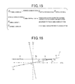
- FIG. 15 is a view illustrating a homogeneous transformation matrix for transforming a camera coordinate to a reference coordinate
- FIG. 16 is a graph for explaining obtaining of an inter-axis offset
- FIG. 17 is a graph illustrating a second embodiment of the present invention.
- FIG. 18 is a graph for explaining obtaining of an inter-axis offset
- FIG. 19 is a perspective view of a flange according to a third embodiment of the present invention.
- FIG. 20 is a perspective view for describing setting of a reference coordinate
- FIG. 21 is a side view illustrating a posture of the flange at target positions of movement
- FIG. 22 is a side view of a robot in a state in which a rotation shaft of each rotation joint is set as an origin position;
- FIG. 23 is a perspective view illustrating a flange portion
- FIG. 24 is a flow diagram illustrating a processing according to the present invention.
- FIGS. 25A and 25B are perspective view and plan view, respectively, illustrating how to determine a reference coordinate
- FIG. 26 is a diagram illustrating deflection of a rotary drive system
- FIG. 27 is a perspective view illustrating target positions of movement
- FIG. 28 is a side view illustrating a forward-bending posture of the robot
- FIG. 29 is a side view illustrating a backward-bending posture of the robot.
- FIG. 30 is a diagram illustrating how to calculate an inter-axis offset
- FIG. 31 is a diagram illustrating a sixth embodiment of the present invention.
- FIG. 32 is a diagram illustrating how to calculate an inter-axis offset
- FIG. 33 is a perspective view illustrating a flange portion
- FIG. 34 is a flow diagram illustrating a processing according to the present invention.
- FIG. 35 is a perspective view illustrating how to determine a reference coordinate
- FIG. 36 is a diagram illustrating a deflection of a rotary drive system
- FIG. 37 is a perspective view illustrating target positions of movement
- FIG. 38 is a side view illustrating a forward-bending posture of the robot
- FIG. 39 is a side view illustrating a backward-bending posture of the robot.
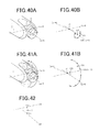
- FIGS. 40A and 40B are diagrams illustrating how to calculate a first linear lines
- FIGS. 41A and 41B are diagrams illustrating how to calculate a second linear lines
- FIG. 42 is a diagram illustrating how to calculate a two-axis orthogonal intersection based on the first and second linear lines
- FIG. 43 is a diagram illustrating how to calculate an inter-axis offset
- FIG. 44 is a perspective view illustrating how to determine a reference coordinate according to an eighth embodiment of the present invention.
- FIG. 45 is a diagram illustrating target positions of movement of a two-axis orthogonal intersection and actual travel positions thereof, according to a ninth embodiment of the present invention.
- FIG. 46 is a diagram illustrating how to calculate an inter-axis offset
- FIGS. 47A and 47B are side view and a bottom view, respectively, of a flange portion according to a tenth embodiment of the present invention.
- FIG. 48 is a perspective view illustrating detected vectors.
- FIG. 1 shows a 6-axis multiple vertical rotation joint type robot apparatus 1 .
- the robot apparatus 1 includes a 6-axis multiple vertical joint type robot (hereinafter, simply referred to as “robot”) 2 , a control unit (robot control means) 3 for controlling the operation of the robot 2 , and a teaching pendent (manual operating means) 4 connected to the control unit 3 to operate the robot 2 through a manual handling.
- robot 6-axis multiple vertical joint type robot
- control unit robot control means
- teaching pendent teaching pendent
- the robot 2 includes a base (base link) 5 fixed to an installation surface, such as a floor of a factory, and a robot arm 6 connected in contact with the base 5 .
- the robot arm 6 includes a shoulder (first link) 7 , a lower arm (second link) 8 , a first upper arm (third link) 9 , a second upper arm (fourth link) 10 , a wrist (fifth link) 11 , and a flange (sixth link) 12 , which are sequentially connected to one another through their respective rotation joints, i.e. first to sixth rotation joints J 1 to J 6 (not shown in FIG. 1 ).
- the shoulder 7 is connected to an upper portion of the base 5 through the first rotation joint J 1 in such a manner that the shoulder 7 is horizontally pivotable around the first axis Lc- 1
- the lower arm 8 is supported by a distal end part of the shoulder 7 through the second rotation joint J 2 in such a manner that the lower arm 8 is vertically pivotable around the second axis Lc- 2
- the first upper arm 9 is supported by a distal end part of the lower arm 8 through the third rotation joint J 3 in such a manner that the first upper arm 9 is vertically pivotable around the third axis Lc- 3
- the second upper arm 10 is supported by a distal end part of the first upper arm 9 through the fourth rotation joint J 4 in such a manner that the second upper arm 10 is twist-rotatable around the fourth axis Lc- 4
- the wrist arm 11 is supported by a distal end part of the second upper arm 10 through the fifth rotation joint J 5 in such a manner that the wrist arm 11 is vertically pivotable around the fifth
- FIG. 2 schematically shows each of the first to sixth rotation to joints J 1 to J 6 .
- each of the rotation joints J 1 to J 6 of the links 7 to 12 includes a rotation shaft 14 rotatably supported by bearings 13 inserted in a link of a previous stage, and the rotation shaft 14 is connected to a link of a next stage either directly or by a coupling member inserted between them.
- the rotation shaft 14 is rotated through a speed reducing device, for example, a gear reducing device 16 , by a servo motor 15 as a driving source fixed to the previous link, and a rotation of the rotation shaft 14 enables a pivoting operation or a twist-rotating operation of the next link.
- first axis Lc- 1 to the sixth axis Lc- 6 correspond to rotation center lines of the rotation shafts 14 of the rotation joints J 1 to J 6 , respectively.
- Orientations of the first axis Lc- 1 to the sixth axis Lc- 6 are as follows. That is to say, the first axis Lc- 1 , which serves as a rotation center of the shoulder 7 , extends in a direction intersecting the installation surface at a right angle, and the second axis Lc- 2 , which serves as a rotation center of the lower arm 8 , extends in a direction parallel to the direction intersecting the first axis Lc- 1 .
- the first axis Lc- 1 extends in a vertical direction with respect to the installation floor surface and the second axis Lc- 2 extends in a horizontal direction.
- the third axis Lc- 3 which serves as a rotation center of the first upper arm 9 , extends in parallel to the second axis Lc- 2 , that is, in a horizontal direction
- the fourth axis Lc- 4 which serves as a rotation center of the second upper arm 10 , extends in a direction parallel to the direction intersecting the third axis Lc- 3
- the fifth axis Lc- 5 which serves as a rotation center of the wrist arm 11 , intersects the fourth axis Lc- 4
- the sixth axis Lc- 6 which serves as a rotation center of the flange 12 , extends in a direction intersecting the fifth axis Lc- 5 .
- the shoulder 7 , the lower arm 8 , the first upper arm 9 , the second upper arm 10 , the wrist arm 11 , and the flange 12 are also located at their origin positions.
- the robot arm 6 is in a vertical upward posture (the lower arm 8 , the first upper arm 9 , the second upper arm 10 , and the wrist arm 11 are vertical) as shown in FIG. 3 .
- the shoulder 7 , the lower arm 8 , the first upper arm 9 , the second upper arm 10 , the wrist arm 11 , and the flange 12 are adapted to also rotate in a normal (plus) direction or an opposite (minus) direction from their origin positions.
- three-dimensional coordinates R 1 to R 6 are defined as shown in FIG. 4 .
- the origins O 1 to O 6 of these coordinates R 1 to R 6 are determined to be disposed at predetermined positions on the first axis Lc- 1 to the sixth axis Lc- 6 , which are the rotation center lines of the shoulder 7 , the lower arm 8 , the first upper arm 9 , the second upper arm 10 , the wrist arm 11 , and the flange 12 , and axes Z 1 to Z 6 , which are z axes of the coordinates R 1 to R 6 , coincide with the first axis Lc- 1 to the sixth axis Lc- 6 , respectively.
- the axis X 1 which is the X-axis of the coordinate R 1 of the shoulder 7 , is determined to horizontally extend in a direction parallel to a common perpendicular line (corresponding to line a in FIG.
- the axis Y 1 which is the Y-axis of the coordinate R 1 of the shoulder 7 , is determined to horizontally extend in a direction obtained by an outer product between vectors of the axis Y 1 and the axis Z 1 (that is, a direction perpendicular to both the axis Y 1 and the axis Z 1 ).
- each of the axes X 2 to X 6 which are the X-axes of the coordinates R 2 to R 6 , is determined to extend in a direction parallel to the axis X 1 of the coordinate R 1 in a state in which the lower arm 8 , the first upper arm 9 , the second upper arm 10 , the wrist arm 11 , and the flange 12 are located in their origin positions, and the axes Y 2 to Y 6 , which are the Y-axes of the coordinates R 2 to R 6 , are determined to extend in a direction obtained by outer products between vectors of the axes Y 2 to Y 6 and the axes Z 1 to Z 6 , respectively (see FIG. 4 ). Further, plus directions of the axes X 1 to X 6 , the axes Y 2 to Y 6 , and the axes Z 1 to Z 6 correspond to the directions indicated by arrows in FIG. 4 .
- coordinates R 0 and Rf are defined, which correspond to distal ends of the base 5 and the robot arm 6 . While the positions and directions of the coordinates R 1 to R 6 change according to the rotations of the shoulder 7 , the lower arm 8 , the first upper arm 9 , the second upper arm 10 , the wrist arm 11 , and the flange 12 , the coordinate R 0 of the base 5 is fixed and serves as a robot coordinate. In the present embodiment, the origin O 0 of the robot coordinate R 0 is determined to be disposed at a position coinciding with the origin O 1 of the coordinate R 1 in the first axis Lc- 1 , which is the rotation center line of the shoulder 7 .
- the axis Z 0 which is a Z-axis, coincides with the first axis Lc- 1
- the axis X 0 which is an X-axis
- the axis Y 0 which is a Y-axis, coincide with the axis X 1 and the axis Y 1 of the coordinate R 1 of the shoulder 7 when the shoulder 7 is located at the origin position.
- the coordinate Rf of the distal end surface of the flange 12 serves as a coordinate of the end effector (i.e., hand), its origin Of is determined to coincide with an intersection point between the sixth axis Lc- 6 and the distal end surface of the flange 12 , that is, to coincide with a center P of the circular distal end surface of the flange 12 as shown in FIG.
- the axis Zf which is a Z-axis
- the axis Xf which is an X-axis
- the axis Yf which is a Y-axis
- the center P of the distal end surface of the flange 12 is determined to be disposed on the end effector, which is the distal end of the robot arm 6 .
- the coordinates R 1 to R 6 and Rf excluding the coordinate R 0 , have origins O 1 to O 6 and Of, which are disposed on the same virtual plane (vertical plane) including the axis X 1 and the axis Z 1 of the coordinate R 1 .
- FIG. 5 illustrates a table in which the DH parameters are arranged.
- DH Densavit-Hartenberg
- FIG. 6 shows detailed numerical examples of a, b, and d.
- the control unit 3 includes a CPU (control means) 17 , a driving circuit (driving means) 18 , and a position detection circuit (position detection means) 19 .
- the CPU 17 is connected to a ROM 20 storing a robot language for making an operation program and a system program of the entire robot 2 and various data, such as DH parameters and a RAM 21 storing the operation program of the robot 2 , and is also connected to the teaching pendent 4 used for a teaching work, etc.
- the teaching pendent 4 includes, as shown in FIG. 1 , various operating units 4 a and a display 4 b formed of a liquid crystal.
- the position detection circuit 19 is connected to a rotary encoder 22 , which serves as a rotation sensor, connected to a rotation shaft (not shown) of each servo motor 15 .
- the position detection circuit 19 detects rotation angles of the shoulder 7 , the lower arm 8 , the first upper arm 9 , the second upper arm 10 , the wrist arm 11 , and the flange 12 based on the detected rotation angle information of each rotary encoder 22 , and provides the detected rotation angle information to the CPU 17 .
- the rotation angles of the shoulder 7 , the lower arm 8 , the first upper arm 9 , the second upper arm 10 , the wrist arm 11 , and the flange 12 which made the position and the posture of the end effector, are obtained by a well-known computation method of inverse dynamics using Jacobian matrix.
- the position and the posture of the end effector on the robot coordinate R 0 can be calculated from the rotation by a well-known computation method of dynamics using coordinate transformation.
- Such computation methods of dynamics and inverse dynamics use the DH parameters indicating the relation between respective coordinates R 0 to R 6 and Rf as well known in the art.
- the CPU 17 calculates target operation angles of the shoulder 7 , the lower arm 8 , the first upper arm 9 , the second upper arm 10 , the wrist arm 11 , and the flange 12 from the target position of the end effector, and then provides an operation command to the driving circuit 18 according to the target operation angles.
- the driving circuit 18 drives each servo motor 15 according to the given operation command.
- the CPU 17 performs a feedback control of each servo motor 15 by using the detected rotation angle information of the shoulder 7 , the lower arm 8 , the first upper arm 9 , the second upper arm 10 , the wrist arm 11 , and the flange 12 fed back from the position detection circuit 19 as feedback information.
- the actually moved position of the end effector is deviated in a horizontal direction from the target position by the sum of inter-axis offsets of the rotation shafts 14 of the rotation joints J 2 and J 3 (when the fifth axis Lc- 5 is vertical) or by the sum of inter-axis offsets of the rotation shafts 14 of the rotation joints J 2 , J 3 , and J 5 (when the fifth axis Lc- 5 is horizontal).
- a method according to the present invention is intended to make the actually moved position of an end effector approach a target position as much as possible by predicting a sum of the inter-axis offsets of the rotation shafts 14 of the rotation joints J 2 , J 3 , and J 5 , and then correcting DH parameters by only the predicted sum of the inter-axis offsets.
- the actually moved position of an end effector is measured by a three-dimensional gauge (three-dimensional measuring means) 23 shown in FIG. 7 , an amount of deviation of the actually moved position from a target position is calculated, and an inter-axis offset is predicted from the calculated deviation amount.
- the deviation between the actually moved position and the target position may be generated by not only the inter-axis offset but also other factors, such as deflection of rotation driving systems of the rotation joints J 1 to J 6 , an origin position error of each servo motor 15 , a length error of each of the links 7 to 12 , and a twist angle error between the rotation shafts 14 of the rotation joints J 1 to J 6 . Therefore, it is necessary to previously perform a correction in order to prevent occurrence of a position error due to such factors.
- the three-dimensional gauge 23 may be a three-dimensional gauge (for example, TOYOU TECHNICA Inc.; ROBOT CALIBRATION ROCAL SYSTEM) equipped with three CCD cameras. Further, the three-dimensional gauge 23 may be a laser tracker, etc. In order to detect the position of the end effector of the robot arm 6 by this three-dimensional gauge 23 , a light emitting diode 24 is provided at the center P of the distal end surface of the flange 12 as a measurement point as shown in FIG. 8 .
- a light emitting diode 24 is provided at the center P of the distal end surface of the flange 12 as a measurement point as shown in FIG. 8 .
- the light emitting diode 24 is disposed at the center within the central hole 12 a and simultaneously is aligned with the distal end surface of the flange 12 , so as to make the light emitting diode 24 be exactly located on the center (end effector) P of the distal end surface of the flange 12 .
- the flange 12 has a small hole 12 b formed thereon, which is formed at a position spaced apart from the central hole 12 a such that a linear lines interconnecting the central hole 12 a and the small hole 12 b can serve as the axis Xf of the end effector coordinate Rf.
- the measurement position of the light emitting diode 24 by the three-dimensional gauge 23 is indicated at a position on a three-dimensional coordinate (hereinafter, referred to as camera coordinate) Rc set in advance in the three-dimensional gauge 23 by a measurement control device 25 including a personal computer.
- a distance corresponding to one gradation of this camera coordinate Rc is determined to be the same as a distance when the end effector has moved by one gradation of the robot coordinate R 0 . Therefore, the length of one gradation of the robot coordinate R 0 and the length of one gradation of the camera coordinate Rc indicate the same distance.
- the method of the present invention is performed by a process as shown in FIG. 9 .
- a reference coordinate Rb is set as a coordinate replacing the robot coordinate R 0 on the camera coordinate Rc (step S 1 of FIG. 9 ).
- the setting of the reference coordinate Rb is performed using the teaching pendent 4 .
- the teaching pendent 4 is configured to be capable of rotating the shoulder 7 , the lower arm 8 , the first upper arm 9 , the second upper arm 10 , the wrist arm 11 , and the flange 12 by only desired angles in normal and reverse directions from their individual origin positions by individually rotating the servo motors 15 of the shoulder 7 , the lower arm 8 , the first upper arm 9 , the second upper arm 10 , the wrist arm 11 , and the flange 12 by only desired angles.
- the teaching pendent 4 is adapted to be capable of appointing the position and posture of the end effector in the robot coordinate R 0 .
- the CPU 17 of the robot apparatus 1 calculates rotation angles of the shoulder 7 , the lower arm 8 , the first upper arm 9 , the second upper arm 10 , the wrist arm 11 , and the flange 12 and operates the respective servo motors 15 so as to make them have the calculated rotation angles.
- the end effector is operated to have the appointed position and posture.
- the CPU 17 computes the position and posture of the end effector from the rotation angles of the shoulder 7 , the lower arm 8 , the first upper arm 9 , the second upper arm 10 , the wrist arm 11 , and the flange 12 , and the display 4 b of the teaching pendent 4 displays the position and posture of the end effector on the robot coordinate R 0 .
- the operating units 4 a of the teaching pendent 4 are operated, so as to make the robot arm 6 have a predetermined posture while maintaining a state in which the fifth axis Lc- 5 , which is the rotation center line of the rotation shaft 14 of the fifth rotation joint J 5 , is parallel to the second axis Lc- 2 and the third axis Lc- 3 , which are rotation center lines of the rotation shafts 14 of the second and third rotation joints J 2 and J 3 , that is, the fifth axis Lc- 5 is horizontal.
- the predetermined posture of the robot arm 6 in this event is maintained to be a posture in which, when the robot arm 6 is rotated around the first axis Lc- 1 , the light emitting diode 24 moves along one rotation trajectory, that is, a posture in which the light emitting diode 24 is spaced apart in the horizontal direction from the first axis Lc- 1 , which corresponds to, in the present embodiment, a posture in which the lower arm 8 and the first upper arm 9 have rotated from the vertical upright state of FIG. 3 so that the flange 12 is oriented slantly downward (a forward-bending posture in which the robot arm 6 has been fallen down forward (plus side of the axis X 0 ) of the shoulder 7 ).
- the shoulder 7 is rotated about the first axis Lc- 1 by a desired angle, preferably at least a total of 180 degrees including the position of plus 90 degrees, the position of 0 degrees (origin position), and the position of minus 90 degrees.
- the position of the light emitting diode 24 on the rotation trajectory E is measured by the three-dimensional gauge 23 at a plurality of positions d 1 , d 2 , . . . , dn including three or more different points. From the plurality of positions d 1 , d 2 , . . .
- the measurement control device 25 calculates the position of the rotation center Ob of the light emitting diode 24 by the least square method and simultaneously obtains a normal line Lv of one plane including the rotation trajectory E of the light emitting diode 24 . Further, the measurement control device 25 determines the position Ob of the rotation center as the origin of the reference coordinate Rb and determines a line, which extends through the origin Ob in parallel to (in the same direction as) the normal line Lv, as the axis Zb (Z-axis) of the reference coordinate Rb.
- a predetermined line extending through the origin Ob and intersecting the axis Zb is determined as the axis Xb (X-axis) of the reference coordinate Rb, and a line intersecting both the axis Zb and the axis Xb is obtained from an outer product between vectors of the axes and is then determined as the axis Yb (Y-axis) of the reference coordinate Rb.
- the length of one gradation of the reference coordinate Rb is determined to be the same as the length of one gradation of the camera coordinate Rc.
- a reference coordinate Rb is set on the camera coordinate Rc.
- the axis Zb is located on the axis Z 0 of the robot coordinate R 0 along the first axis Lc- 1 and the XbYb plane is parallel to the X 0 -Y 0 plane. Further, if there is no inter-axis offset, the axis Xb and the axis Yb are parallel to the axis X 0 and the axis Y 0 .
- the axis Xb and the axis Yb are not parallel to the axis X 0 and the axis Y 0 and are inclined according to the inter-axis offset as shown in FIG. 16 .
- the Xb-Yb plane coincides with the X 0 -Y 0 plane.
- one vertical plane including the axis Zb is taken into consideration and a plurality of positions within the plane are determined as target positions of movement.
- a predetermined extension line A 1 extending from the axis Zb (origin b) is set on the Xb-Yb plane of the reference coordinate Rb, and an extension line A 2 extending from the axis Zb in the opposite direction to the predetermined extension line A 1 is also set on the Xb-Yb plane.
- This extension line A 1 in one direction and the extension line A 2 in the opposite direction configure one linear lines A passing through the axis Zb, and the linear lines A is located within one plane including the axis Zb.
- the predetermined extension line A 1 is specified by an angle by which the predetermined extension line A 1 makes with respect to the axis Xb.
- the shoulder 7 is rotated 30 degrees from the origin.
- a plurality of such linear lines A are set (although FIGS. 10 and 12 show only one of them), and one linear lines A among the plurality of linear lines A is parallel to the axis Xb.
- a plurality of positions are optionally selected on each of the extension lines A 1 and A 2 . Accordingly, the plurality of optionally selected positions on each of the extension lines A 1 and A 2 exist in one vertical plane including the axis Zb. The plurality of optionally selected positions are indicated by small white empty circles in FIG. 12 . To the plurality of optionally selected positions on each linear lines A, the end effector of the robot arm 6 is moved as described later, in order to obtain the inter-axis offset.
- the plurality of optionally selected positions on the linear lines A are positions indicated by coordinate values (Xb, Yb, Zb) of the reference coordinate Rb
- the target positions of movement of the end effector operated by the teaching pendent 4 are indicated the coordinate values (X 0 , Y 0 , Z 0 ) of the reference coordinate Rb.
- the position of the light emitting diode 24 on the axis Z 0 in the obtained reference coordinate Rb corresponds to the position (this position is referred to as Za) of the reference coordinate Rb on the axis Z 0 of the Xb-Yb plane.
- each of the target positions of movement is appointed by three-dimensional coordinate values toward the robot coordinate R 0 , and the end effector is moved to the appointed position. Then, the actually moved position of the end effector may be deviated in the Xb-Yb direction by only a distance corresponding to the inter-axis offset from the target position of movement on the reference coordinate Rb obtained as described above. Therefore, from the amount of the deviation, it is possible to calculate an amount of deviation of the inter-axis offset.
- the following description is based on an assumption that the axis Zb of the reference coordinate Rb is located on the axis Z 0 of the robot coordinate R 0 and the axis Xb and the axis Yb of the reference coordinate Rb are parallel to the axis X 0 and the axis Y 0 of the robot coordinate R 0 .
- a process of removing an error in the moved position of the end effector which may be caused by the errors (including a deflection of a rotation driving system, an origin position error of the servo motor 15 , a twist angle error, and a link length error) other than the inter-axis offset, is performed.
- the deflection of a rotation driving system refers to a deflection in a twist direction caused by the transmission torque from the rotation shaft of the servo motor 15 through the gear reducing device 16 up to rotation shaft 14 of the first to sixth rotation joints J 1 to J 6 . It is assumed that the rotation shaft 14 is not bent in a shape of a circular arc in the axial direction.
- the deflection of a rotation driving system can be obtained from a torque applied to the rotation driving system and a spring constant of the rotation driving system.
- the spring constant is already known in the robot 2 and the value thereof is stored in advance in the ROM 20 of the control unit 3 .
- the torque applied to the rotation driving system will be discussed in relation to the second axis Lc- 2 , the third axis Lc- 3 , and the fifth axis Lc- 5 (a large torque is not applied to and a deflection causing an absolute position error is not generated in the first axis Lc- 1 , the fourth axis Lc- 4 , and the sixth axis Lc- 6 ).
- the torque applied to the rotation driving system can be obtained by a multiplication between a distance D from the rotation shaft 14 to the center of the link L supported by the rotation shaft 14 and the mass W of the link L, as shown in FIG. 11 .
- the end effector of the robot arm 6 is moved to a plurality of optionally selected positions on the linear lines A, the end effector is moved to the positions while maintaining the fifth axis Lc- 5 in parallel to the second axis Lc- 2 and the third axis Lc- 3 , for example, by rotating only the lower arm 8 and the first upper arm 9 without rotating the shoulder 7 , the second upper arm 10 , the wrist arm 11 , and the flange 12 .
- the rotation angles of the second upper arm 10 , the lower arm 8 , the first upper arm 9 , the wrist arm 11 , and the flange 12 by the movement to the positions are read from the teaching pendent 4 , the torques applied to the second axis Lc- 2 , the third axis Lc- 3 , and the fifth axis Lc- 5 are calculated from the rotation angles, and the deflection (torsion angle) ⁇ of the rotation driving system is obtained (step S 2 of FIG. 9 ).
- the rotation angle of the servo motor 15 is increased or decreased as much as the deflection ⁇ of the rotation driving system, so as to make the servo motor 15 be in a state equal to the state in which there is no deflection. That is, in FIG. 11 , if the position of the link indicated by a solid line corresponds to a target position of movement when there is no deflection in the rotation driving system and the position indicated by a broken line corresponds to an actually moved position when there is a deflection in the rotation driving system, the rotation angle of the servo motor 15 is reduced by the deflection ⁇ . As a result, in a state in which the rotation driving system is bent, the link can reach the target position of movement of the solid line.
- the motor origin position error is detected by, for example, methods disclosed in patent documents of JPA 2003-220587, No. 2009-274186, No. 2009-274187, and No. 2009-274188 described above. Further, the twist angle error and the link length error are detected by, for example, a method disclosed in the JARA report described above. According to the method of the JARA report, the rotation trajectory of the end effector when the robot arm 6 is rotated around each of the first axis Lc- 1 to the sixth axis Lc- 6 is measured by a three-dimensional gauge, and a normal line of one plane including a rotation trajectory and a position of a rotation center is computed.
- the DH parameter is corrected by the obtained motor origin position error, link length error, and twist angle error, so as to prevent such errors from appearing as absolute position errors (step S 4 of FIG. 9 ).
- the teaching pendent is handled to first align the axis X 1 of the coordinate R 1 of the shoulder 7 with one desired extension line A 1 among the plurality of extension lines.
- the shoulder 7 is rotated from the origin position by only an angle made between the extension line A 1 and the axis Xb (equal to the axis X 0 ) when there is no inter-axis offset.
- this rotation which corresponds to a rotation of the rotation shafts 14 of the second rotation joint J 2 and the third rotation joint J 3 , the end effector can be moved to a plurality of target positions of movement arranged on the linear lines A 1 and A 2 .
- the robot arm 6 moves the end effector to a target position of movement on the linear lines A 1 of one direction in a posture (forward-bending posture) in which it has been fallen down forward in said one direction from the shoulder 7 , by rotating the rotation shafts 14 of at least the second rotation joint J 2 and the third rotation joint J 3 among the second rotation joint J 2 , the third rotation joint J 3 , and the fifth rotation joint J 5 in said one direction, as shown in FIG. 13 .
- the robot arm 6 moves the end effector into a posture (backward-bending posture) in which the robot arm 6 is inverted and has been fallen down backward in the opposite direction from the shoulder 7 , by rotating the rotation shafts 14 of at least the second rotation joint J 2 and the third rotation joint J 3 among the second rotation joint J 2 , the third rotation joint J 3 , and the fifth rotation joint J 5 in the opposite direction, as shown in FIG. 14 .
- the position of the light emitting diode (measurement point for measuring an offset) 24 is measured by the three-dimensional gauge 23 (step S 5 of FIG. 9 ). Since the position measured by the three-dimensional gauge 23 is a position of the camera coordinate Rc, the measured position is transformed into a position of the reference coordinate Rb. This transformation is performed by a homogeneous transformation matrix as shown in FIG. 15 (step S 6 of FIG. 9 ).
- the errors between the target positions of movement and the actually moved positions are divided into errors in the Zb axis direction and errors on the Xb-Yb plane, based on the coordinate values of Xb, Yb, and Zb in the reference coordinate Rb (the Xb and Yb coordinate values are equal to the X 0 and Y 0 coordinate value on the robot coordinate R 0 and the Zb coordinate value is 0).
- FIG. 16 shows the errors on the Xb-Yb plane with respect to a plurality of target positions of movement arranged on the linear lines A 1 and A 2 coinciding with the axis Xb.
- linear lines A 1 and A 2 are linear lines coinciding with the axis Xb.
- the white empty circles indicate target positions of movement on the robot coordinate R 0
- the black solid circles indicate target positions of movement on the reference coordinate Rb
- the x marks indicate actually moved positions of the end effector.
- segments interconnecting target positions of movement determined on the linear lines A 1 and A 2 and actually moved positions are drawn on the Xb-Yb plane and are put as measurement dependence segments 5 , and a shortest distance between a linear lines Bb obtained by extending the measurement dependence segments and the origin Ob, i.e. the length of a perpendicular line to the line Bb from the origin Ob, is then obtained. Then, the obtained shortest distance corresponds to the inter-axis offset F (step S 7 of FIG. 9 ).
- the shortest distance to the origin Ob is measured.
- the shortest distance between the origin Ob and these measurement dependence linear lines B is all the same regardless of the measurement dependence linear lines B. However, it actually occurs frequently that the shortest distances are not always the same due to the measurement error, etc.
- the inter-axis offset is calculated by obtaining an average of the shortest distances between the origin Ob and these measurement dependence linear lines B, by which it is possible to obtain a more exact inter-axis offset.
- the inter-axis offset obtained in the way described above corresponds to a sum of inter-axis offsets generated in relation to the second axis Lc- 2 , the third axis Lc- 3 , and the fifth axis Lc- 5 , and it is impossible to analyze the sum of the inter-axis offsets and determine the axis or axes to which the offsets relate.
- the inter-axis offset value is added into one cell of the d column of J 2 and J 3 or the inter-axis offset values are divisionally added into cells of the d column of J 2 and J 3 .
- the fifth axis Lc- 5 can have any angle between the horizontal and the vertical by the rotation of the fourth axis Lc- 4 , a distribution of inter-axis offsets to cells of the d column of J 5 may degrade the absolute position accuracy to the contrary. By this reason, the inter-axis offsets are not distributed in the cells of the d column of J 5 .
- FIG. 17 shows the second embodiment of the present invention.
- the components which are similar or identical to those described in the first embodiment will be given the same reference numerals for the sake of a simplified explanation.
- the reference coordinate Rb is obtained in the same way as in the first embodiment, a different method is employed in obtaining the inter-axis offset.
- the inter-axis offset is obtained based on a difference between a target position of movement and an actually moved position. That is to say, the inter-axis offset is put as “0” and a plurality of positions on the reference coordinate Rb are optionally selected as target positions of movement. Further, since the inter-axis offset is put as “0”, the Xb and Yb coordinate values on the reference coordinate Rb are equal to the X 0 and Y 0 coordinate values on the robot coordinate R 0 .
- the plurality of positions selected as the target positions of movement are indicated by solid black circles.
- a movement of the end effector to a target position of movement of the plus side (the right side of Yb) of the Xb coordinate value is carried out by a forward-bending posture of the robot arm 6 and a movement of the end effector to a target position of movement of the minus side (the left side of Yb) is carried out by a backward-bending posture of the robot arm 6 .
- a process of removing an error in the moved position of the end effector which may be caused by the errors (including a deflection of a rotation driving system, an origin position error of the servo motor 15 , a twist angle error, and a link length error) other than the inter-axis offset, is performed.
- the end effector is moved to the plurality of selected target positions of movement.
- the movement in this event is performed by rotating the rotation shafts 14 of the first rotation joint J 1 and the second and third rotation joints J 2 and J 3 among the second, third and fifth rotation joints J 2 , J 3 , and J 5 .
- the rotation shaft 14 of the fourth rotation joint J 4 is not rotated.
- the position of the light emitting diode 24 at each target position of movement is measured by the three-dimensional gauge 23 .
- the measured position is transformed into a position of the reference coordinate Rb.
- Measurement positions of the light emitting diode 24 at respective target positions of movement are indicated by x marks in FIG. 17 .
- the measurement positions of the light emitting diode 24 and the Xb-Yb coordinate values (equal to the X 0 -Y 0 coordinate values) at the target positions of movement indicated by black circles in FIG. 17 are plotted on the Xb-Yb coordinate surface of the reference coordinate Rb, a length of a segment from the origin Ob to a target position of movement is put as a target position radius D 0 , and a length of a perpendicular line from a measurement position of the light emitting diode 24 to a linear lines extending through the origin Ob and the target position of movement is put as an offset error component M 0 .
- a graph having a transverse axis indicating the target position radius D 0 and a longitudinal axis indicating the offset error component M 0 is drawn, dots reflecting the relation between target position radiuses D 0 and the offset error components M 0 for respective target positions of movement are plotted, and a linear lines passing through the plotted dots is put as an error linear lines G. Then, if a perpendicular line is drawn from the origin of the graph to the error linear lines G, the length of the perpendicular line corresponds to the sum of inter-axis offsets F of the second, third, and fifth rotation joints.
- FIGS. 19 to 21 show the third embodiment of the present invention.
- the light emitting diode 24 is not attached to the end effector (center of a distal end surface of the flange 12 ), but is attached to a predetermined position on the flange 12 spaced apart in the direction of diameter from the rotation center line Lc- 6 of the sixth rotation joint J 6 .
- a support 26 on which the light emitting diode 24 is mounted is attached to a predetermined position spaced apart from a center P of a distal end surface of the flange 12 .
- the fifth axis Lc- 5 which is the rotation center line of the rotation shaft 14 of the fifth rotation joint J 5
- the second axis Lc- 2 and the third axis Lc- 3 which are rotation center lines of the rotation shafts 14 of the second and third rotation joints J 2 and J 3 , that is, the fifth axis Lc- 5 is maintained to be horizontal.
- the center P of the flange 12 is maintained to be spaced apart in the horizontal direction from the first axis Lc- 1 .
- the wrist arm 11 is maintained to be oriented vertically downward as shown in FIG. 21 .
- the shoulder 7 is rotated around the first axis Lc- 1 .
- the shoulder 7 is stopped at a plurality of predetermined angle positions, and the flange 12 is rotated at the stopped positions.
- the wrist arm 11 is not required to have a posture in which it is especially oriented in the vertically downward direction.
- the light emitting diode 24 is integrally rotated together. Therefore, at three or more different positions on the rotation trajectory of the light emitting diode 24 , the position of the light emitting diode 24 on the camera coordinate Rc is measured by the three-dimensional gauge 23 .
- a center of the rotation trajectory of the light emitting diode 24 is obtained.
- the centers C 1 , C 2 , . . . , and Cn of the rotation trajectory of the light emitting diode 24 at the respective stopped angle position of the shoulder 7 are located on the rotation center line Lc- 6 of the rotation shaft 14 of the sixth rotation joint J 6 and serve as virtual end effector positions for setting a reference coordinate.
- a center of a circle passing the virtual end effector positions C 1 , C 2 , . . . , and Cn for setting a reference coordinate is obtained by the least square method, and a normal line Lv of one plane including the circle is simultaneously obtained. Then, the center Ob of the circle is determined as the origin of the reference coordinate Rb, and a linear lines, which extends through the origin Ob of the circle in parallel to the normal line Lv, is determined as the axis Zb of the reference coordinate Rb.
- a predetermined line extending through the origin Ob and intersecting the axis Zb is determined as the axis Xb (X-axis) of the reference coordinate Rb, and a line intersecting both the axis Zb and the axis Xb is obtained from an outer product between vectors of the axes and is then determined as the axis Yb (Y-axis) of the reference coordinate Rb.
- a reference coordinate Rb is set on the camera coordinate Rc.
- a plurality of linear lines each of which is configured by linear lines A 1 and A 2 , are selected, a plurality of predetermined target positions of movement on the linear lines A 1 and A 2 are selected, and an inter-axis offset is then obtained.
- a process of removing an error in the moved position of the end effector which may be caused by the errors (including a deflection of a rotation driving system, an origin position error of the servo motor 15 , a twist angle error, and a link length error) other than the inter-axis offset, is performed.
- the end effector of the robot arm 6 is moved to the plurality of selected positions.
- the wrist arm 11 may have any posture.
- the end effector is moved to a target position of movement by rotating the rotation shafts 14 of the second, third, and fifth rotation joints J 2 , J 3 , and J 5 so that the end effector is moved while maintaining a posture in which the sixth axis Lc- 6 of the flange coordinate R 6 is maintained to be oriented in the vertically downward direction as shown in FIG. 21 (the sixth axis Lc- 6 is in parallel with the first axis Lc- 1 ).
- the flange 12 is rotated. Then, since the light emitting diode 24 is also rotated by the rotation of the flange 12 , three or more different predetermined positions on the rotation trajectory of the light emitting diode 24 are measured by the three-dimensional gauge 23 . Then, from the measured three or more different predetermined positions on the rotation trajectory of the light emitting diode 24 , a center position (a virtual end effector position for calculating the offset) of the rotation trajectory of the light emitting diode 24 is obtained and the obtained virtual end effector position for calculating the offset is subjected to a coordinate transformation from the camera coordinate Rc to the reference coordinate Rb. Since the wrist arm 11 is oriented vertically downward, the Xb and Yb coordinate values of the virtual end effector position for calculating the offset are identical to the Xb and Yb coordinate values of the end effector.
- a length of a perpendicular line from the origin Ob onto an extension line of segments obtained by interconnecting a plurality of virtual end effector positions for calculating the offset is obtained as an amount of deviation, which corresponds to an inter-axis offset.
- the Xb and Yb coordinate values of the virtual end effector position for calculating the offset are identical to the Xb and Yb coordinate values of the end effector when the wrist arm 11 is oriented vertically downward, the wrist arm 11 is not required to be oriented vertically downward if the fifth axis Lc- 5 is parallel to the second and third axes Lc- 2 and Lc- 3 .
- the movement to the target positions of movement is carried out while maintaining a state in which the fifth axis Lc- 5 , which is the rotation center line of the wrist arm 11 , is maintained to be horizontal, and the virtual end effector position for calculating the offset is thus located on a line parallel to the axis X 0 (e.g.
- a support 26 on which the light emitting diode 24 is mounted is attached to a predetermined position spaced apart from a center (end effector) P of a distal end surface of the flange 12 .
- the reference coordinate Rb is obtained in the same process as that of the third embodiment. The only difference between the third embodiment and the fourth embodiment lies in the method of obtaining the inter-axis offset.
- the inter-axis offset is obtained by the same method as that of the second embodiment. That is, a plurality of target positions of movement are selected at each of the plus side (the right side of Yb in FIG. 17 ) and the minus side (the left side of Yb in FIG. 17 ) of the Xb coordinate value. Then, for the plurality of selected target positions of movement, a process of removing an error in the moved position of the end effector, which may be caused by the errors (including a deflection of a rotation driving system, an origin position error of the servo motor 15 , a twist angle error, and a link length error) other than the inter-axis offset, is performed.
- the errors including a deflection of a rotation driving system, an origin position error of the servo motor 15 , a twist angle error, and a link length error
- the end effector is moved to the plurality of selected target positions of movement.
- the movement is carried out by rotating the rotation shafts 14 of the first rotation joint J 1 and two or more rotation joints among the second, third, and fifth rotation is joints J 2 , J 3 , and J 5 , especially in the present embodiment, three rotation joints including the second, third, and fifth rotation joints J 2 , J 3 , and J 5 , so that the movement can be performed while maintaining a state in which the fifth axis Lc- 5 is parallel to the second and third axes Lc- 2 and Lc- 3 and the wrist arm 11 is oriented vertically downward, that is, the axis Z 6 of the coordinate R 6 of the flange is oriented vertically downward (the sixth axis Lc- 6 is parallel to the first axis Lc- 1 ).
- the flange 12 is rotated, and three or more positions on the rotation trajectory of the light emitting diode 24 are measured by the three-dimensional gauge 23 . From the three or more positions on the rotation trajectory of the light emitting diode 24 , a center position (a virtual end effector position for calculating the offset) of the rotation trajectory of the light emitting diode 24 is obtained, and the virtual end effector position for calculating the offset is then subjected to a coordinate transformation from the camera coordinate Rc to the reference coordinate Rb.
- the target positions of movement and the virtual end effector positions (corresponding to the measurement positions of the light emitting diode 24 in FIG. 17 ) for calculating the offset are plotted on the Xb-Yb coordinate surface of the reference coordinate Rb, a length of a segment from the origin Ob to a target position of movement is put as a target position radius D 0 , and a length of a perpendicular line from a virtual end effector position for calculating the offset onto a linear lines extending through the origin Ob and the target position of movement is put as an offset error component M 0 .
- the sixth axis Lc- 6 which is the rotation center line of the sixth rotation joint J 6 , is not parallel to the first axis Lc- 1 , that is, if it is not vertical
- the Xb and Yb coordinate values of the virtual end effector position for calculating the offset are changed according to the inclination angle of the rotation center Lc- 6 , and the offset error component M 0 is also changed by that change.
- the sixth axis Lc- 6 which is the rotation center line of the sixth rotation joint J 6 , be vertical (Lc- 6 is parallel to Lc- 1 ), in order to make the Xb and Yb coordinate values of the virtual end effector position for calculating the offset be identical to the Xb and Yb coordinate values of the end effector.
- the axis Xb of the reference coordinate Rb is not required to be necessarily parallel to the axis X 0 , and any linear lines passing through the origin Ob may be selected as the axis Xb of the reference coordinate Rb.
- a relation between the reference coordinate Rb and the robot coordinate Rc may be obtained, so that a position on the reference coordinate Rb and a position on the robot coordinate Rc can be transformed into each other through a coordinate transformation between the reference coordinate Rb and the robot coordinate Rc based on the obtained relation.
- a predetermined extension line A 1 extending from the axis Zb is set on the Xb-Yb plane of the reference coordinate Rb
- an extension line A 2 extending from the axis Zb in the opposite direction to the predetermined extension line A 1 is also set on the Xb-Yb plane
- a plurality of positions on each of the extension lines A 1 and A 2 are optionally selected as target positions of movement.
- a plurality of optional positions within one plane (a vertical plane) including the axis Zb may be selected as target positions of movement.
- the target position of movement and the actually moved position of the end effector show no difference and have the same value in the Xb axis direction and the Yb axis direction if they have the same Xb-Yb coordinate values even when there is a difference in the Zb axis coordinate value.
- the end effector in moving the end effector to a plurality of target positions of movement, the end effector can be moved to a selected target position of movement by rotating the rotation shaft 14 of one rotation joint among the second, third, and fifth rotation joints J 2 , J 3 , and J 5 .
- the end effector when the end effector is moved from the linear lines A 1 (a plane extending in one direction from the axis Zb) to a target position of movement of the linear lines A 2 (a plane extending in the opposite direction from the axis Zb), the end effector may be moved to the target position of movement in a state in which the robot arm 6 is inverted according to the selected target position of movement by rotating the rotation shaft 14 of one rotation joint among the second, third, and fifth rotation joints J 2 , J 3 , and J 5 .
- the end effector in moving the end effector to a plurality of optionally selected target positions of movement, the end effector may be moved by rotating the rotation shafts 14 of either all of the second, third, and fifth rotation joints J 2 , J 3 , and J 5 or any two rotation joints selected among them.
- the end effector may be moved to the target position of movement by rotating the rotation shaft 14 of one rotation joint among the second, third, and fifth rotation joints J 2 , J 3 , and J 5 , in addition to the rotation shaft 14 of the first rotation joint J 1 .
- the end effector may be moved to the target position of movement by rotating a rotation shaft of at least one rotation joint.
- the end effector in moving the end effector to target positions of movement while maintaining a state in which the rotation center line Lc- 6 of the sixth rotation joint J 6 is parallel to the rotation center line Lc- 1 of the first rotation joint J 1 , the end effector may be moved to selected target position of movement by rotating the rotation shafts 14 of any two rotation joints selected among the second, third, and fifth rotation joints J 2 , J 3 , and J 5 .
- the end effector in moving the end effector to target positions of movement while maintaining a state in which the sixth axis Lc- 6 corresponding to the rotation center line of the sixth rotation joint J 6 is parallel to the first axis Lc- 1 corresponding to the rotation center line of the first rotation joint J 1 , the end effector may be moved to selected target position of movement by rotating the rotation shafts 14 of two or more rotation joints among the second, third, and fifth rotation joints J 2 , J 3 , and J 5 .
- FIG. 22 shows a side view of a robot according to the present embodiment.
- the flange 12 has an end surface to which the support 26 is attached at an optional position distanced from the center P.
- the support 26 has an end portion to which a light emitting diode (LED) 24 as a measurement point is attached.
- the three-dimensional gauge 23 measures the position of the LED 24 .
- a three-dimensional coordinate (hereinafter referred to as camera coordinate) Rc is set in advance to the three-dimensional gauge 23 by a measurement controller (measurement control means) 26 composed of a computer. Positions where the three-dimensional gauge 23 measures the position of the LED 24 are indicated on the camera coordinate.
- the distance expressed by one graduation of the camera coordinate Rc is determined so as to be equal to the distance resulting from the movement of the end effector (i.e. hand) through one graduation of the robot coordinate R 0 . Accordingly, the length of one graduation of the robot coordinate R 0 expresses the same distance as that expressed by the length (unit length) of one graduation of the camera coordinate Rc.
- the method according to the present invention is realized by the processing shown in FIG. 24 .
- a reference coordinate Rb is determined on the camera coordinate Rc, instead of the robot coordinate R 0 , (step S 1 of FIG. 24 ).
- the motion of the robot arm 6 for determining the reference coordinate Rb is given by the teaching pendant 4 .
- the teaching pendant 4 is configured to separately rotate the servomotors 15 of the shoulder 7 , lower arm 8 , first upper arm 9 , second upper arm 10 , wrist arm 11 and the flange 12 by a desired angle.
- the shoulder 7 , lower arm 8 , first upper arm 9 , second upper arm 10 , wrist arm 11 and flange 12 are rotated from the respective origin positions by a desired angle in forward and reverse directions.
- the teaching pendant 4 is able to specify the rotational position of the shoulder 7 , and the positions and postures of the lower arm 8 , first upper arm 9 , second upper arm 10 , wrist arm 11 , flange 12 and the end effector on the robot coordinate R 0 .
- the CPU 17 of the robotic device 1 calculates the rotation angles of the shoulder 7 , lower arm 8 , first upper arm 9 , second upper arm 10 , wrist arm 11 and flange 12 , and drives the respective servomotors 15 to achieve the respective rotation angles.
- the shoulder 7 , lower arm 8 , first upper arm 9 , second upper arm 10 , wrist arm 11 , flange 12 and the end effector are moved so as to take the specified positions and postures.
- the positions and postures of the shoulder 7 , lower arm 8 , first upper arm 9 , second upper arm 10 , wrist arm 11 , flange 12 and the end effector correspond to the coordinates R 1 to R 6 and Rf.
- the CPU 17 acquires the rotation angles of the shoulder 7 , lower arm 8 , first upper arm 9 , second upper arm 10 , wrist arm 11 and flange 12 , calculates the positions and postures of the shoulder 7 , lower arm 8 , first upper arm 9 , second upper arm 10 , wrist arm 11 , flange 12 and the end effector and displays the calculated positions and postures in terms of the robot coordinate R 0 , on the display 4 b of the teaching pendant 4 .
- initial positions of the shoulder 7 and the flange 12 are determined first.
- the control panel 4 a of the teaching pendant 4 is operated to rotate the lower arm 8 and the first upper arm 9 from an upright posture shown in FIG. 22 .
- the robot arm 6 adopts a forward-bending posture, as shown in FIG. 28 , for example, in which the robot arm 6 is inclined forward (plus side of the X 1 axis) with respect to the shoulder 7 .
- the robot arm 6 may adopt a backward-bending posture as sown in FIG. 29 so as to be inclined backward with respect to the shoulder 7 .
- the shoulder 7 is rotated to an appropriate (optional) position.
- the fifth axis Lc- 5 which is the rotation center line of the rotary shaft 14 of the fifth rotary joint J 5
- the sixth axis Lc- 6 which is the rotation center line of the rotary shaft 14 of the sixth rotary joint J 6
- is made parallel to the first axis Lc- 1 which is the rotation center line of the first rotary joint J 1 , i.e. brought to a vertical position, being directed vertically downward.
- the sixth axis Lc- 6 may be made parallel to the first axis Lc- 1 , being directed vertically upward.
- the flange 12 is rotated to an appropriate rotational position.
- the shoulder 7 is rotated to an appropriate rotational position while the flange 12 is also rotated to an appropriate rotational position by controlling the teaching pendant 4 .
- These rotational positions are determined to be initial rotational positions of the shoulder 7 and the flange 12 .
- it is desirable that the flange 12 is at an initial rotational position where the image of the LED 24 is easily picked up by the three-dimensional gauge 23 , i.e. where the LED 24 is located nearer to the three-dimensional gauge 23 than to the sixth axis Lc- 6 , irrespective of the position of the end effector.
- the shoulder 7 is rotated so as to be located at a plurality of optional rotational positions C 1 , C 2 . . . en (see FIG. 25B ).
- the fifth axis Lc- 5 is maintained parallel to the second and third axes Lc- 2 and Lc- 3
- the sixth axis Lc- 6 is maintained parallel to the first axis Lc- 1 .
- the flange 12 is rotated from its initial rotational is position in a direction opposite to the direction of rotation of the shoulder 7 from its initial rotational position to the current rotational position.
- the flange 12 is rotated by an angle corresponding to the angle of rotation of the shoulder 7 from its initial rotational position to the current rotational position.
- the flange 12 is brought to a state of being rotated counterclockwise by 30° from its initial rotational position.
- the flange 12 is rotated in a direction opposite to the rotation of the shoulder 7 by the same angle of rotation of the shoulder 7 at each rotational position of the shoulder 7 .
- the LED 24 is constantly located at the initial position as viewed from the plus side of the Z 0 axis, with the robot coordinate R 0 being translated along the sixth axis Lc- 6 .
- the position of the LED 24 as a measurement point for determining the reference coordinate is measured by the three-dimensional gauge 23 .
- three or more measurement positions d 1 , d 2 , . . . dn of the LED 24 are provided on a circular rotation locus E centering on a vertical axis which is parallel to the first axis Lc- 1 (Z 0 axis).
- the measurement controller 26 calculates a position Ob that is the rotation center of the LED 24 using a least-square method, based on the plurality of positions d 1 , d 2 , . . . dn on the rotation locus E of the LED 24 measured by the three-dimensional gauge 23 .
- the measurement controller 26 calculates a normal line Lv with respect to a plane including the plurality of positions d 1 , d 2 , . . . dn of the LED 24 .
- the position Ob that is the rotation center of the LED 24 is determined to be an origin of the reference coordinate Rb.
- the linear lines passing through the origin Ob and parallel to (directed to the same direction as) the normal line Lv, i.e. a vertical axis parallel to the first axis Lc- 1 is determined to be a Zb axis (Z axis) of the reference coordinate Rb.
- an optional linear lines passing through the origin Ob and intersecting the Zb axis at right angle is determined to be an Xb axis (X axis) of the reference coordinate Rb.
- the Xb axis may be a linear line connecting the origin Ob and a position P 0 of the LED 24 when the shoulder 7 is rotated to the origin position.
- a linear lines that intersects both of the Zb and Xb axes at right angles is calculated based on an outer product of these axes and determined to be a Yb axis (Y axis) of the reference coordinate Rb.
- the length of one graduation in the reference coordinate Rb is made equal to that of one graduation in the camera coordinate Rc, and accordingly, in the robot coordinate R 0 .
- the reference coordinate Rb is determined on the camera coordinate Rc.
- the Zb axis is parallel to the first axis Lc- 1 and thus to the Z 0 axis of the robot reference R 0
- the Xb-Yb plane is parallel to the X 0 -Y 0 plane.
- the Xb-Yb plane coincides with the X 0 -Y 0 plane.
- the Zb axis is present in a predetermined direction from the Z 0 axis being apart therefrom by a predetermined distance.
- the positional relationship between the Z 0 axis and the Zb axis is the same as the positional relationship between the sixth axis Lc- 6 and the LED 24 when the flange 12 is at the initial rotational position.
- the direction from the Z 0 axis to the Zb axis coincides with the direction from the sixth axis Lc- 6 to the LED 24 when the flange 12 is at the initial position.
- the distance from the Z 0 axis to the Zb axis is equal to the distance from the sixth axis Lc- 6 to the LED 24 .
- the Xb and Yb axes are parallel to the X 0 and Y 0 axes of the robot coordinate R 0 .
- the position P 0 of the LED 24 when the shoulder 7 is rotated to the origin position (0°) is offset in the X 0 -Y 0 direction by an amount corresponding to the inter-axis offset, in determining the reference coordinate Rb.
- the Xb and Yb axes are not parallel to the X 0 and Y 0 axes, respectively, but inclined in conformity with the inter-axis offset.
- an optional plane A 1 is assumed, as shown in FIG. 27 , which is extended from the first axis Lc- 1 and includes the first axis Lc- 1 .
- the plane A 1 is specified by an angle with respect to the X 0 axis.
- the shoulder 7 may be rotated from the origin position by plus 30° (in the absence of an inter-axis offset).
- a plane A 2 is assumed, which is extended from the Z 0 axis in the opposite direction.
- the planes A 1 and A 2 are flush with each other and form a single plane A.
- a plurality of positions are optionally selected as target positions of movement on the assumed plane A 1 extending in one direction and the plane A 2 extending in the opposite direction.
- the selected target positions of movement are indicated by small hollow circles.
- the target positions of movement are specified by values on the robot coordinate R 0 .
- the end effector of the robot arm 6 is moved to each of the target positions of movement to calculate an inter-axis offset.
- the plurality of selected target positions of movement on the planes A 1 and A 2 are specified by values on the robot coordinate R 0 .
- the end effector is moved to each of the target positions of movement with the fifth axis Lc- 5 being maintained parallel to the second and third axes Lc- 2 and Lc- 3 and the sixth axis Lc- 6 being maintained parallel to the first axis-Lc- 1 (the target position reaching posture of the flange 12 ).
- the flange 12 is rotated from its initial rotational position in a direction opposite to the direction of rotation of the shoulder 7 from its initial rotational position to the current target position of movement. In this case, the flange 12 is rotated by an angle of rotation of the shoulder 7 from its initial rotational position to the current target rotational position (initial position retention motion).
- the positional relationship between the LED 24 and the end effector (center P of the end surface of the flange 12 ) at this moment is the same as the positional relationship between the reference coordinate Rb and the robot coordinate R 0 , regarding the directions X 0 (Xb) and Y 0 (Yb).
- the position of the end effector is moved in a direction from the origin O 0 of the robot coordinate R 0 toward the origin Ob of the reference coordinate Rb, as viewed from the plus side of the Z 0 axis, by a distance corresponding to the distance from the origins O 0 to Ob. With this movement, each position of the LED 24 on the rotation locus E is achieved.
- values X 0 , Y 0 on the robot coordinate R 0 for indicating a target position of movement of the end effector become equal to values Xb, Yb on the reference coordinate Rb for indicating the position of the LED 24 when the end effector has moved to a target position of movement (in the absence of an inter-axis offset).
- the flange 12 should be in a state of having conducted the initial position retention motion in the target position reaching posture.
- the Xb-Yb position of the LED 24 on the reference coordinate Rb at this moment is rendered to be a target position of movement of the LED 24 .
- a travel position error Prior to the movement of the end effector of the robot arm 6 to target positions of movement selected on the planes A 1 and A 2 , a travel position error is removed.
- the travel position error is ascribed to various errors (deflection of rotary drive systems, origin position error of the servomotors 15 , torsion angle error and link-length error) other than the inter-axis offset.
- the deflection of the rotary drive systems corresponds to a deflection in the direction of torsion, which is caused by torque transmitted from the rotary shafts of the servomotors 15 to the rotary shafts 14 of the respective rotary joints J 1 to J 6 via the respective reduction gears 16 .
- each rotary shaft 14 causes no arc deflection in the axial direction.
- the deflection in each rotary drive system may be calculated from the torque acting on the rotary drive system and the spring constant of the rotary drive system. The spring constant has been obtained in advance in the robot 2 and stored in the ROM 20 of the control unit 3 .
- the torque acting on each rotary drive system is calculated based on the product of a mass W of a link L supported by the rotary shaft 14 , and a distance D from the rotary shaft 14 to the center of the link L.
- the shoulder 7 is rotated to an angular position that matches the angle of the plane A with respect to the X 0 axis to maintain the fifth axis Lc- 5 parallel to the second and third axes Lc- 2 and Lc 3 .
- the robot arm 6 adopts the forward-bending posture or the backward-bending posture depending on the target position of movement.
- the rotation angles of the second upper arm 10 , lower arm 8 , first upper arm 9 , wrist arm 11 and flange 12 after movement to each target position of movement are read from the teaching pendant 4 .
- the torque acting on the second, third and fifth axes Lc- 2 , Lc- 3 and Lc- 5 are calculated to obtain deflection (angle) ⁇ of the rotary drive systems (step S 2 of FIG. 24 ).
- the rotation angle of each servomotor 15 is adjusted by an angle corresponding to the obtained deflection ⁇ of the rotary drive system so as to be equivalent to the case where no deflection is caused. Specifically, in FIG.
- the position of the link indicated by a solid line is a target position of movement when the rotary drive system has no deflection
- the position indicated by a broken line is an actual travel position when the rotary drive system has a deflection.
- the rotation angle of each servomotor 15 is reduced by an angle corresponding to the deflection ⁇ .
- the link reaches the actual target position of movement indicated by the solid line in a state where the rotary drive system has a deflection.
- the motor origin position error is detected using the method disclosed, for example, in the known patent documents JP-2003-220587-A, JP-2009-274186-A, JP-2009-274187-A or JP-2009-274188-A.
- the torsion angle error and the link-length error are detecting using the method disclosed, for example, in the non-patent document “3-pair Joint Axis Estimating Method”, 4.3.2, page 52, a report on “Investigation research on standardization of intelligent robots for plants” (1997), JARA (Japan Robot Association)”.
- the robot arm 6 is rotated about the first to six axes Lc- 1 to Lc- 6 .
- the rotation trajectory of the end effector is measured by a three-dimensional gauge to calculate the position of the rotation center and a normal line with respect to the plane that includes the rotation trajectory.
- the length of each link is calculated from the rotation center position and the direction of each axis is calculated from the direction of the normal line. Accordingly, the link-length error and the torsion angle error are calculated from the length of each link and the direction of the axis (step S 3 of FIG. 24 ).
- the DH parameters are corrected so that the errors will not appear in the form of an absolute position error (step S 4 of FIG. 24 ).
- the teaching pendant 4 is operated to move the end effector to each target position of movement on each plane A.
- the shoulder 7 is rotated first from the origin position by the angle ⁇ of the plane A 1 with respect to the X 0 axis to have the X 1 axis of the coordinate R 1 positioned on the plane A.
- the rotary shafts 14 of the second, third and fifth rotary joints J 2 , J 3 and J 5 are rotated.
- the end effector is moved to the target positions of movement on the planes A 1 and A 2 , with the flange 12 being in the target position reaching posture.
- the flange 12 carries out the initial position retention motion. Then, the lower arm 8 , the first upper arm 9 and the wrist arm 11 are rotated while the flange 12 is maintained in the target position is reaching posture. Thus, the end effector is moved to each of the plurality of optionally selected target positions of movement on the planes A 1 and A 2 . In this case, the robot arm 6 adopts the same posture as the one when the torque acting on the rotary drive systems has been calculated. Also, the rotation angle of each servomotor 15 is adjusted according the deflection of the rotary drive system, which has been calculated for each target position of movement.
- the robot arm 6 When the end effector is moved to the plurality of optionally selected target positions of movement on the planes A 1 and A 2 , the rotary shafts 14 of the second, third and fifth rotary joints J 2 , J 3 and J 5 of the robot arm 6 are rotated, as shown in FIG. 28 , in one direction.
- the robot arm 6 being inclined to one direction, or being bent forward at the shoulder 7 (forward-bending posture), is able to move the end effector to the target positions of movement on the plane A 1 .
- the timing for the flange 12 to carry out the initial position retention motion is not limited to the timing after the X 1 axis is positioned on the plane A 1 but before the end effector is moved to each target position of movement.
- the timing may be when the end effector has been moved to each target position of movement.
- the initial position retention motion is not required to be performed any more at the subsequent target positions of movement.
- the position measured by the three-dimensional gauge 23 corresponds to a position on the camera coordinate Rc. Accordingly, the position on the camera coordinate Rc is converted to a position on the reference coordinate Rb. The conversion is performed using a homogeneous transformation matrix shown in FIG. 15 (step S 6 of FIG. 24 ).
- FIG. 30 shows: target positions of movement (indicated by values of the robot coordinate R 0 ) of the end effector as seen from the plus side of the Z 0 axis; target positions of movement (indicated by values of the reference coordinate Rb) of the LED 24 ; actual positions of the end effector when moved to the target positions of movement; and positions of the LED 24 (which are converted from the values on the camera coordinate Rc to the values on the reference coordinate Rb) when the end effector is moved to the target positions of movement.
- the planes A 1 and A 2 are assumed to be on the X 0 axis and the target positions of movement of the end effector are assumed to have been selected from positions on the X 0 axis.
- double circles indicate target positions of movement of the end effector
- hollow circles indicate actual travel positions of the end effector
- filled circles indicate target positions of movement of the LED 24
- cross marks indicate actual travel positions of the LED 24 .
- the error caused by the inter-axis offset allows the actual travel positions to be aligned along a line parallel to the X 0 axis, which line is offset from the target positions of movement by an amount corresponding to the inter-axis offset.
- the actual travel positions if not precisely linearly aligned, will be distributed along a linear line.
- the inter-axis offset corresponds to a distance between each target position of movement of the end effector and the actual travel position thereof in the X 0 -Y 0 direction. This distance is equal to the distance between each target position of movement of the LED 24 and the actual travel position thereof in the Xb-Yb direction in the absence of an inter-axis offset (when the Xb axis is parallel to the X 0 axis). Accordingly, the plurality of actual travel positions of the LED 24 are connected to provide a measurement dependent line segment B on the Xb-Yb plane. The measurement dependent line segment B is extended to provide a linear lines Bb. A minimum distance between the linear lines Bb and the origin Ob of the reference coordinate Rb (length of a perpendicular dropped from Ob to Bb) is calculated. The calculated minimum distance corresponds to an inter-axis offset F (step S 7 of FIG. 24 ).
- An inter-axis offset F is calculated in a manner similar to the above, for target positions of movement set in similar planes including the Xb axis, other than the planes A 1 and A 2 .
- the actual travel positions of the LED 24 should align.
- a minimum distance to the origin Ob is similarly measured for the measurement dependent line segment B obtained by connecting the actual travel positions (Xb, Yb coordinate values) of the LED 24 .
- All the measurement dependent line segments B should have an even minimum distance to the origin Ob. In practice, however, the minimum distance is often not necessarily even due to a measurement error, for example. In such a case, an average of the minimum distances from the respective the measurement dependent line segments B to the origin Ob is obtained to calculate an inter-axis offset. Thus, an inter-axis offset is more accurately calculated.
- the inter-axis offset calculated as described above is a sum of inter-axis offsets caused in the second, third and fifth axes Lc- 2 , Lc- 3 and Lc- 5 , and thus there is no analyzing regarding correlation of the calculated inter-axis offset to these axes. Accordingly, of the DH parameters shown in FIG. 5 , either one of the parameters in the column “d” of J 2 and J 3 is added with the inter-axis offset, or the parameters in the column “d” of J 2 and J 3 are permitted to share the inter-axis offset.
- the fifth axis Lc- 5 can have any angle between a horizontal line and a vertical line depending on the rotation of the fourth axis Lc- 4 . Accordingly, when the inter-axis offset is distributed to the column “d” of J 5 , the accuracy of absolute position is rather impaired. For this reason, the inter-axis offset is not distributed to the column “d” of J 5 .
- position error on the Xb-Yb plane was reduced from 0.67 mm to 0.17 mm.
- Position error in the Zb axis direction was also reduced from 0.9 mm to 0.06 mm.
- position error was reduced from 1.12 mm to 0.18 mm, regarding the Xb-Yb-Zb three-dimensional direction.
- the inter-axis offset is quantitatively grasped. Based on the inter-axis offset, DH parameters are corrected so that an error due to the inter-axis offset will not occur, or such an error occurs as less as possible. Thus, the absolute position accuracy is enhanced.
- FIGS. 31 and 32 show a sixth embodiment of the present invention.
- the reference coordinate Rb is obtained in a manner similar to the fifth embodiment.
- the sixth embodiment is different from the fifth embodiment in the process of calculating an inter-axis offset.
- a plurality of optional positions are set as target positions of movement in a movable range of the end effector.
- an inter-axis offset is calculated based on the difference between each target position of movement and the actual travel position of the LED 24 .
- a plurality of positions as target positions of movement are optionally selected first on the robot coordinate R 0 .
- double circles indicate the plurality of positions selected as target positions of movement.
- FIG. 31 shows positions only in the horizontal direction (X 0 -Y 0 direction, Xb-Yb direction).
- the end effector is moved to the target positions of movement on the plus side of the X 0 coordinate values (right side with respect to the Y 0 axis) in a state where the robot arm 6 is in the forward-bending posture.
- the end effector is moved to the target positions of movement on the minus side (left side with respect to the Y 0 axis) in a state where the robot arm 6 is in the backward-bending posture.
- a travel position error due to several errors other than an inter-axis offset is removed prior to the movement of the end effector to the plurality of selected target positions of movement.
- the several errors include deflection of the rotary drive systems, origin position errors of the servomotors 15 , torsion angle error and link-length error.
- the end effector is moved, in the target position reaching posture, to the plurality of selected target positions of movement.
- the end effector is moved by rotating the rotary shafts 14 of at least two rotary joints among the first, second, third and fifth rotary joints J 1 , J 2 , J 3 and J 5 (in the present embodiment, three rotary joints, i.e. second, third and fifth rotary joints J 2 , J 3 and J 5 ).
- the rotary shaft 14 of the fourth rotary joint J 4 is not rotated in order to maintain the fifth axis Lc- 5 at a horizontal position.
- the position of the LED 24 is measured by the three-dimensional gauge 23 , with the flange 12 being in a state of having conducted the initial position retention motion.
- the position measured by the three-dimensional gauge 23 corresponds to the position on the camera coordinate Rc and thus the position is converted to the position on the reference coordinate Rb.
- Measurement positions of the LED 24 at the individual target positions of movement are indicated by cross marks in FIG. 31 .
- the Xb values and the Yb values on the reference coordinate Rb are required to be calculated for the target positions of movement of the LED 24 .
- the Xb and Yb axes of the reference coordinate Rb are parallel to the X 0 and YD axes, respectively. Therefore, the X 0 , Y 0 coordinate values indicating the movement of the end effector are equal to the Xb, Yb coordinate values when the target positions of movement of the LED 24 are indicated on the robot coordinate Rb.
- the target positions of movement of the LED 24 expressed by the Xb, Yb values on the reference coordinate Rb are plotted, as shown in FIG. 31 by filled circles.
- the length of a line segment from the origin Ob to each target position of movement is rendered to be a target position radius D 0 .
- the length of a perpendicular dropped from a measurement position of the LED 24 on a linear lines passing through the origin Ob and a target position of movement is rendered to be an offset error component M 0 .
- a graph is prepared as shown in FIG. 32 , in which the horizontal axis indicates the target position radius D 0 and the vertical axis indicates the offset error component M 0 .
- the target position radii D 0 relative to the offset error components M 0 of the individual target positions of movement are plotted.
- a linear lines passing through the plotted points is rendered to be an error linear lines G.
- the length of the perpendicular corresponds to en inter-axis offset F that is a sum of the inter-axis offsets of the second, third and fifth rotary joints.
- the fixation surface of the base 5 does not have to be necessarily horizontal.
- the measurement point is not limited to the LED 24 .
- the measurement point may simply be a mark, or desirably, may be a dot-like mark.
- the Xb axis of the reference coordinate Rb does not have to be necessarily parallel to the X 0 axis.
- An optional linear lines passing through the origin Ob may be used as the Xb axis.
- an angle between the optional linear lines (Xb axis) and the X 0 axis is calculated based on an angle between the X 1 and X 0 axes when the Xb axis is determined and based on the initial position of the LED 24 .
- a relationship between the reference coordinate Rb and the robot coordinate R 0 is calculated based on the angle between the Xb and X 0 axes, followed by coordinate conversion.
- a position on the reference coordinate Rb is converted to that on the robot coordinate R 0 , or vice versa.
- the end effector is moved from the plane A 1 (plane extending in one direction from the Zb axis) to the target positions of movement on the plane A 2 (plane extending in the opposite direction from the Zb axis).
- the rotary shafts 14 of two of the second, third and fifth rotary joints J 2 , J 3 and J 5 may be rotated, depending on the selected target positions of movement.
- the robot arm 6 is turned around to move the end effector to the target positions of movement.
- the end effector is moved to the plurality of optionally selected target positions of movement.
- the rotary shafts 14 of all of or any two of the second, third and fifth rotary joints J 2 , J 3 and J 5 may be rotated.
- the rotary joints 14 of two of the second, third and fifth rotary joints J 2 , J 3 and J 5 may be rotated, in addition to the first rotary joint J 1 to move the end effector to the target positions of movement.
- the rotary shafts of at least two rotary joints may be rotated.
- the support 26 is attached to an optional position of the flange 12 to calculate the position of the two-axis orthogonal intersection C.
- the support 26 has an end portion which is provided with a light emitting diode (LED) 24 as a measurement point.
- LED light emitting diode
- a three-dimensional gauge 23 is fixed to measure the position of the LED 24 .
- the method according to the present invention is performed based on a processing shown in FIG. 34 .
- a coordinate as a reference coordinate Rb is determined on the camera coordinate Rc, instead of the robot coordinate R 0 (step S 1 of FIG. 34 ).
- the reference coordinate Rb is determined using the teaching pendant 4 .
- the teaching pendant 4 is configured to individually rotate the servomotors 15 of a shoulder 7 , lower arm 8 , first upper arm 9 , second upper arm 10 , wrist arm 11 and flange 12 by a desired angle.
- the shoulder 7 , lower arm 8 , first upper arm 9 , second upper arm 10 , wrist arm 11 and flange 12 are rotated by a desired angle from the respective origin positions in forward and reverse directions.
- the teaching pendant 4 is able to specify the positions and postures of the shoulder 7 , lower arm 8 , first upper arm 9 , second upper arm 10 , wrist arm 11 , flange 12 and an end effector on the robot coordinate R 0 .
- the CPU 17 of the robotic device 1 calculates the rotation angles of the shoulder 7 , lower arm 8 , first upper arm 9 , second upper arm 10 , wrist arm 11 and flange 12 and drives the servomotors 15 to realize the rotation angles.
- coordinates R 1 to R 6 and Rf as well as the end effector are operated so as to realize the specified positions and postures.
- the CPU 17 calculates the positions and postures of the shoulder 7 , lower arm 8 , first upper arm 9 , second upper arm 10 , wrist arm 11 , flange 12 and the end effector, based on the rotation angles of the shoulder 7 , lower arm 8 , first upper arm 9 , second upper arm 10 , wrist arm 11 and flange 12 and displays the calculated positions and postures in terms of the robot coordinate R 0 , on the display 4 b of the teaching pendant 4 .
- the positions and postures of the shoulder 7 , lower arm 8 , first upper arm 9 , second upper arm 10 , wrist arm 11 , flange 12 and the end effector correspond to the positions and postures on the coordinates R 1 to R 6 and Rf.
- the control panel 4 a of the teaching pendant 4 is operated to have the robot arm 6 adopted an optional posture.
- the robot arm 6 adopts a posture in which the LED 24 is ensured to be located at a position horizontally distanced from the first axis Lc- 1 , in a state where the fifth axis Lc- 5 is maintained parallel to the second and third axes Ic- 2 and Lc- 3 , i.e. maintained at a horizontal position.
- the present embodiment as shown in FIG.
- the robot arm 6 is maintained in a forward-bending posture in which the lower arm 8 and the first arm 9 are rotated to have the flange 12 inclined obliquely downward (posture in which the robot arm 6 is inclined front side with respect to the shoulder 7 (plus side of the X 0 axis)), turning from the upright posture (refer to FIG. 22 ).
- the posture adopted at this moment may be the backward-bending posture as shown in FIG. 39 .
- the LED 24 is horizontally distanced from the first axis Lc- 1 so that, when the robot arm 6 is rotated about the first axis Lc- 1 , the LED 24 moves on a rotation locus.
- the shoulder 7 is rotated about the first axis Lc- 1 by a desired angle, or desirably, rotated by 180° or more including an angle from a plus 90° position to a minus 90° position via a 0° position (origin position).
- the fifth axis Lc- 5 is not necessarily required to be made parallel to the first and second axes Lc- 2 and Lc- 3 .
- the LED 24 as a measurement point for determining the reference coordinate traces a circular rotation locus E centering on the first axis Lc- 1 .
- the three-dimensional gauge 23 measures three or more of the positions d 1 , d 2 , . . . dn on the rotation locus E of the LED 24 .
- the measurement controller 25 calculates a position Ob that is the rotation center of the LED 24 using a least-square method based on the plurality of positions d 1 , d 2 , . . . dn on the rotation locus E of the LED 24 , which have been measured by the three-dimensional gauge 23 .
- the measurement controller 24 calculates a normal line Lv with respect to a plane that includes the rotation locus E of the LED 24 .
- the measurement controller 25 determines the position Ob of rotation center to be an origin of the reference coordinate Rb and determines a linear lines passing through the origin Ob and parallel to the normal line Lv (directed in the same direction as the normal line Lv) to be a Zb axis (Z axis) of the reference coordinate Rb.
- the measurement controller 25 determines an optional linear lines intersecting the Zb axis at right angle and passing through the origin Ob to be an Xb axis (X axis) of the reference coordinate Rb.
- the linear lines corresponds to the linear lines connecting a position P 0 of the LED 24 to the origin Ob when the shoulder 7 is rotated to the origin position.
- the measurement controller 25 also calculates a linear lines intersecting the Zb and Xb axes at right angles from an outer product of these axes for use as a Yb axis (Y axis) of the reference coordinate Rb.
- the length of one graduation in the reference coordinate Rb is made equal to that of one graduation in the camera coordinate Rc.
- the reference coordinate Rb is determined on the camera coordinate Rc.
- the Zb axis coincides with the first axis Lc- 1 and accordingly coincides with the Z 0 axis of the robot coordinate R 0
- the Xb-Yb plane is parallel to the X 0 -Y 0 plane.
- the Xb-Yb plane coincides with the X 0 -Y 0 plane.
- the Xb and Yb axes are parallel to the X 0 and Y 0 axes of the robot coordinate R 0 .
- the position P 0 of the LED 24 when the shoulder 7 is rotated to the origin position is offset in the X 0 -Y 0 direction by an amount corresponding to the inter-axis offset.
- the Xb and Yb axes are not parallel to the X 0 and Y 0 axes but are inclined, as shown in FIGS. 41A and 41B , in conformity with the inter-axis offset.
- a vertical plane is assumed, which is an extension from the first axis Lc- 1 in an optional direction and includes the first axis Lc- 1 .
- a plurality of target positions of movement are set in the plane.
- planes A 1 and A 2 are assumed.
- the plane A 1 is an optional plane extended from the Zb axis or the Z 0 axis coinciding with the first axis Lc- 1 in an optional direction and including the Z 0 axis.
- the plane A 2 is a plane extended from the Z 0 axis in a direction opposite to the direction of the plane A 1 .
- the planes A 1 and A 2 are flush with each other forming a single plane A.
- FIGS. 35 and 37 show only one plane A.
- One of the planes A includes the X 0 axis.
- Each plane A is specified by an angle ⁇ with respect to the X 0 axis.
- a plurality of target positions of movement are optionally selected on each of the planes A 1 and A 2 .
- the plurality of optionally selected target positions of movement are indicated by small hollow circles.
- the two-axis orthogonal intersection C is moved to the plurality of optionally selected target positions of movement on the planes A 1 and A 2 , in a state where the fifth axis Lc- 5 is parallel to the second and third axes Lc- 2 and Lc- 3 , for the purpose of calculating an inter-axis offset.
- the plurality of positions selected on the plane A are specified by values (of X 0 , Y 0 , Z 0 ) on the robot coordinate R 0 .
- the Zb axis of the reference coordinate Rb coincides with the Z 0 axis, while the Xb and Yb axes in the absence of an inter-axial offset are parallel to the X 0 and Y 0 axes, respectively. Accordingly, the X 0 and Y 0 coordinate values of each target position of movement are equal to the Xb and Yb coordinate values on the reference coordinate Rb.
- the origin Ob of the reference coordinate Rb is distanced from the origin O 0 of the robot coordinate R 0 .
- the position of the LED 24 on the Z 0 axis after calculating the reference coordinate Rb corresponds to the position of the origin Ob of the reference coordinate Rb (this position is designated as Za). Therefore, the Zb coordinate value in the reference coordinate Rb at each target position of movement is expressed by (Z 0 -Za).
- the Xb and Yb axes are parallel to the X 0 and Y 0 axes, respectively. Accordingly, in the absence of an inter-axis offset, the robot coordinate R 0 after being translated along the Z 0 axis to the position Za coincides with the reference coordinate Rb.
- the correlation between the reference coordinate Rb and the robot coordinate R 0 in the absence of an inter-axis offset is used for calculating an inter-axis offset.
- each target position of movement is specified by three-dimensional values in the robot coordinate R 0 and the two-axis orthogonal intersection C is moved thereto.
- the actual travel position of the two-axis orthogonal intersection C is deviated in the Xb-Yb direction from the target position of movement on the reference coordinate Rb calculated as described above, by an amount corresponding to the inter-axis offset.
- an inter-axis offset can be calculated from the amount of deviation of the two-axis orthogonal intersection C.
- the two-axis orthogonal intersection C coincides with the origins O 5 and O 6 of the coordinate R 5 of the wrist arm 11 and the coordinate R 6 of the flange 12 , respectively. Accordingly, using the teaching pendant 4 , the two-axis orthogonal intersection C is moved to each target position of movement by moving the coordinate R 5 of the wrist arm 11 or the coordinate R 6 of the flange 12 to the target position of movement.
- the fifth axis Lc- 5 Prior to the movement of the two-axis orthogonal intersection C of the robot arm 6 to the plurality of optionally selected positions on the planes A 1 and A 2 , the fifth axis Lc- 5 , for example, may be made parallel to the second third axes Lc- 2 and Lc- 3 . Then, the rotary axes 14 of the second and third rotary joints J 2 and J 3 may be rotated.
- the deflection of the rotary drive system corresponds to the deflection in the direction of torsion caused by the torque transmitted from the rotary shafts of the respective servomotors 15 to the rotary shafts 14 of the rotary joints J 1 to J 6 via the respective reduction gears 16 . It should be appreciated that each rotary shaft 14 causes no arc deflection in the axial direction.
- the deflection in each rotary drive system may be calculated from the torque acting on the rotary drive system and the spring constant of the rotary drive system. The spring constant is obtained in advance in the robot 2 and stored in the ROM 20 of the control unit 3 .
- the torque acting on the rotary drive system is discussed regarding the second, third and fifth axes Lc- 2 , Lc- 3 and Lc- 5 (no large torque acts on the first, fourth and sixth axes Lc- 1 , Lc- 4 and Lc- 6 and thus there is no deflection that causes absolute position error).
- the torque acting on each rotary drive system is calculated based on the product of a mass W of a link L supported by the rotary shaft 14 , and a distance D from the rotary shaft 14 to center of the link L.
- the fifth axis Lc- 5 is maintained parallel to the second and third axes Lc- 2 and Lc- 3 , while the lower arm 8 and the first upper arm 9 are rotated to move the two-axis orthogonal intersection C to the optionally selected plurality of positions.
- rotation angles of the second upper arm 10 , lower arm 8 , first upper arm 9 , wrist arm 11 and flange 12 when being moved to the positions, are read from the teaching pendant 4 .
- torque acting on the second, third and fifth axes Lc- 2 , Lc- 3 and Lc- 5 are calculated.
- a deflection (angle) ⁇ of each rotary drive system caused by the torque is calculated (step S 2 of FIG. 34 ).
- the rotation angle of each of the servomotors 15 is adjusted by an angle corresponding to the obtained deflection ⁇ of the rotary drive system so as to be equivalent to the case where no deflection is caused.
- the position of the link indicated by a solid line is a target position of movement when the rotary drive system has no deflection
- the position indicated by a broken line is an actual travel position when the rotary drive system has a deflection.
- the rotation angle of each servomotor 15 is reduced by an angle corresponding to the deflection ⁇ .
- the link reaches the actual target position of movement indicated by the solid line in a state where the rotary drive system has a deflection.
- the motor origin position error is detected using a known method and the torsion angle error and the link-length error are detecting using a known method (step S 3 of FIG. 34 ).
- the DH parameters are corrected so that the errors will not appear in the form of an absolute position error (step S 4 of FIG. 34 ).
- the teaching pendant 4 is operated, so that, among the plurality of planes A 1 , the X 1 axis of the coordinate R 1 of the shoulder 7 matches a desired one plane A 1 .
- the shoulder 7 is rotated from its origin position by an angle ⁇ with respect to the X 0 axis of the plane A 1 .
- the two-axis orthogonal intersection C is moved to the plurality of target positions of movement on the planes A 1 and A 2 .
- the rotary shafts 14 of the second and third rotary joints J 2 and J 3 are rotated in a state where the fifth axis Lc- 5 is maintained parallel to the second and third axes Lc- 2 and Lc- 3 .
- the fifth axis Lc- 5 is maintained at a horizontal position
- only the lower arm 8 (second axis Lc- 2 ) and the first arm 9 (third axis Lc- 3 ) are rotated to move the two-axis orthogonal intersection C to the plurality of optionally selected target positions of movement on the planes A 1 and A 2 .
- the rotation angles of the servomotors 15 are adjusted in conformity with the deflection of the rotary drive systems calculated in advance for each target position of movement.
- the robot arm 6 When the end effector is moved to the plurality of optionally selected target positions of movement on the planes A 1 and A 2 , the rotary shafts 14 of the second and third rotary joints J 2 and J 3 of the robot arm 6 are rotated, as shown in FIG. 38 , in one direction.
- the robot arm 6 being inclined to one direction, or being bent forward at the shoulder 7 (forward-bending posture), is able to move the end effector to the target positions of movement on the plane A 1 .
- the rotary shafts 14 of the second and third joints J 2 and J 3 are rotated in the other direction.
- the robot arm 6 being turned around and inclined to the other direction, or being bent backward at the shoulder 7 (backward-bending posture) is able to move the two-axis orthogonal intersection C to the target positions of movement.
- the following operation is performed to estimate the actual position of the two-axis orthogonal intersection C.
- the rotary shaft 14 of the sixth rotary joint Lc- 6 is rotated at each target position of movement.
- the LED 24 moves along a circular rotation locus with this rotation, three or more different positions of the LED 24 on the rotation locus are measured by the three-dimensional gauge 23 .
- the measured three or more positions of the LED 24 are used for calculating a center position C 6 of the rotation locus of the LED 24 and a normal line V 6 with respect to a plane that includes the three or more positions on the rotation locus of the LED 24 .
- a first linear lines L 6 is calculated, which passes through the center of the rotation locus of the LED 24 and is parallel to the normal line V 6 (first operation).
- the rotary shaft 14 of the fifth rotary joint Lc- 5 is rotated.
- the LED 24 moves along a circular rotation locus with this rotation, three or more different positions of the LED 24 on the rotation locus are measured by the three-dimensional gauge 23 .
- the measured three or more positions of the LED 24 are used for calculating a center position C 5 of the rotation locus of the LED 24 and a normal line V 5 with respect to a plane that includes the three or more positions on the rotation locus of the LED 24 .
- a second linear lines L 5 is calculated, which passes through the center of the rotation locus of the LED 24 and is parallel to the normal line V 5 (second operation).
- intersection of the first and second linear lines L 6 and L 5 is rendered to be a measurement position of the two-axis orthogonal intersection C.
- a method of calculating the measurement position (the camera coordinate Rc) of the two-axis orthogonal intersection C is set forth below.
- the center position C 6 on the camera coordinate is expressed by (X 6 , Y 6 , Z 6 ) and the normal line V 6 (vector) is expressed by (l 6 , m 6 , n 6 ).
- the center position C 5 on the camera coordinate is expressed by (X 5 , Y 5 , Z 5 ) and the normal line V 5 (vector) is expressed by (l 5 , m 5 , n 5 ).
- the normal lines V 6 and V 5 each indicate a unit vector, while (l 6 , m 6 , n 6 ) and (l 5 , m 5 , n 5 ) indicate lengths obtained by decomposing the normal lines V 6 and V 5 , respectively, in directions along Xc, Yc and Zc axes.
- Equation P 2 in Formula (2) expresses a linear lines passing through the center position C 5 and parallel to the normal line V 5 .
- ( x,y,z ) ( X 5, Y 5, Z 5)+ s ( l 5, m 5, n 5)
- P 2 C 5+ s ⁇ V 5 (2)
- t and s indicate parameters.
- the values s and t can be calculated from Formulas (3) and (4).
- the calculated s and t are substituted into Formulas (1) and (2), nearest points N 1 and N 2 of the two linear lines are obtained.
- averaging the calculated nearest points N 1 and N 2 of the two linear lines the position of the two-axis orthogonal intersection C is obtained.
- the nearest points N 1 and N 2 of the two linear lines will have the same value.
- the position of the two-axis orthogonal intersection C calculated in this way is on the camera coordinate Rc and thus is converted to a position on the reference coordinate Rb.
- the conversion is performed using a homogeneous transformation matrix shown in FIG. 15 (step S 6 of FIG. 34 ).
- FIG. 43 shows the Xb-Yb plane of the reference coordinate Rb.
- the plurality of target positions of movement are rendered to be present on the X 0 axis.
- small hollow circles indicate the target positions of movement of the two-axis orthogonal intersection C on the robot coordinate R 0 .
- Filled circles indicate the target positions of movement of the two-axis orthogonal intersection C on the reference coordinate Rb (the Xb, Yb coordinate values are equal to the X 0 , Y 0 coordinate values).
- Cross marks indicate measurement positions of the two-axis orthogonal intersection C.
- the error between each target position of movement and the actual travel position is regarded as being caused by an inter-axis offset. Since the target positions of movement are on a vertical plane (on the X 0 axis here), the error caused by the inter-axis offset allows the measurement positions of the two-axis orthogonal intersection C to be aligned along a line which is offset from the target positions of movement on the robot coordinate R 0 by an amount corresponding to the inter-axis offset.
- the measurement positions of the two-axis orthogonal intersection C if not precisely linearly aligned, will be distributed along a linear line.
- a line segment connecting between the measurement positions is rendered to be a measurement dependent line segment B.
- a linear lines extended from the measurement dependent line segment B is rendered to be a linear lines Bb.
- a minimum distance between the linear lines Bb and the origin Ob is calculated. The calculated minimum distance corresponds to an inter-axis offset F (step S 7 of FIG. 34 ).
- the inter-axis offset F is calculated similarly for the target positions of movement set in each of other similar planes than the planes A 1 and A 2 that include the X 0 axis. In this case as well, the actual travel positions of the end effector should align.
- the target positions of movement set in each of other planes A than the plane A that includes the X 0 axis are connected to provide a measurement dependent line segment B.
- a minimum distance between the measurement dependent line segment B and the origin Ob is similarly measured for each of other planes A.
- All the measurement dependent line segments B should have a uniform distance to the origin Ob. In practice, however, the minimum distance is often not necessarily uniform due to a measurement error, for example. In such a case, an average of the minimum distances between the respective measurement dependent line segments B and the origin Ob is obtained to calculate an inter-axis offset. Thus, an inter-axis offset is more accurately calculated.
- the inter-axis offset calculated as described above is a sum of inter-axis offsets caused in the second, third and fifth axes Lc- 2 , Lc- 3 and Lc- 5 , and thus there is no analyzing regarding correlation of the calculated inter-axis offset to these axes. Accordingly, of the DH parameters shown in FIG. 5 , either one of the parameters in the column “d” of J 2 and J 3 is added with the inter-axis offset, or the parameters in the column “d” of J 2 and J 3 are permitted to share the inter-axis offset.
- the fifth axis Lc- 5 can have any angle between a horizontal line and a vertical line depending on the rotation of the fourth axis Lc- 4 . Accordingly, when the inter-axis offset is distributed to the column “d” of J 5 , the accuracy of absolute position is rather impaired. For this reason, the inter-axis offset is not distributed to the column “d” of J 5 .
- position error on the Xb-Yb plane was reduced from 0.67 mm to 0.17 mm.
- Position error in the Zb axis direction was also reduced from 0.9 mm to 0.06 mm.
- position error was reduced from 1.12 mm to 0.18 mm, regarding the Xb-Yb-Zb three-dimensional direction.
- the inter-axis offset is quantitatively grasped. Based on the inter-axis offset, DH parameters are corrected so that an error due to the inter-axis offset will not occur, or such an error occurs as less as possible. Thus, the absolute position accuracy is enhanced.
- FIG. 44 shows an eighth embodiment of the present invention.
- the reference coordinate Rb is determined using a method different from that of the first embodiment.
- the subsequent method of calculating an inter-axis offset is the same as that of the first embodiment.
- the reference coordinate Rb is determined using the two-axis orthogonal intersection C. Specifically, of the rotary shafts 14 of the first to sixth rotary joints J 1 to J 6 , the rotary shafts 14 of at least the second to fourth rotary joints J 2 to J 4 are fixed. In this state, the shoulder 7 is rotated to three or more optional angular positions by the rotary shaft 14 of the first rotary joint J 1 . Then, a first linear lines L 6 (the sixth axis Lc- 6 that is the rotation center line of the flange 12 ) is calculated at each of these angular positions by performing the first operation described in the seventh embodiment.
- a second linear lines L 5 (the fifth axis Lc- 5 that is the rotation center line of the wrist arm 11 ) is calculated by performing the second operation. After that, an intersection of the first and second linear lines L 6 and L 5 , i.e. the two-axis orthogonal intersection C, is calculated for use as a measurement position of the two-axis orthogonal intersection C.
- Such measurement positions of the two-axis orthogonal intersection C are present on a circle E centering on the first axis Lc- 1 .
- the measurement controller 25 calculates a center position of the circle E that passes through the measurement positions of the two-axis orthogonal intersection C, and a normal line Lv with respect to a plane that includes the measurement positions of the two-axis orthogonal intersection C. Then, the measurement controller 25 determines the reference coordinate Rb.
- the origin Ob corresponds to the center of the circle E.
- the Zb axis corresponds to a linear lines passing through the origin Ob and parallel to the normal line Lv.
- the Xb axis corresponds to any optional linear lines passing through the origin Ob and intersecting the Zb axis at right angle.
- the Yb axis corresponds to a linear lines passing through the origin Ob and intersecting the Zb and Xb axes at right angles.
- FIGS. 45 and 46 show a ninth embodiment of the present invention.
- the reference coordinate Rb is calculated similar to the seventh or eighth embodiment.
- an inter-axis offset is calculated using a method different from that in the seventh embodiment.
- a plurality of optional positions are set within a range in which the two-axis orthogonal intersection C is movable.
- an inter-axis offset is calculated based to a difference between the target position of movement and the actual travel position of the two-axis orthogonal intersection C.
- a plurality of optional positions are optionally selected as target positions of movement on the robot coordinate R 0 .
- the X 0 , Y 0 values of each target position of movement specified on the robot coordinate R 0 are equal to the Xb, Yb values on the reference coordinate Rb (in the absence of the inter-axis offset).
- the plurality of selected positions as the target positions of movement are indicated by filled circles.
- the robot arm 6 moves to these positions in a forward-bending posture.
- the robot arm 6 moves to these positions in a backward-bending posture.
- travel position error of the two-axis orthogonal intersection C caused by several errors other than the inter-axis offset is removed.
- the several errors include deflection of the rotary drive systems, origin position errors of the servomotors 15 , torsion angle error and link-length error.
- the two-axis orthogonal intersection C is moved to the plurality of selected target positions of movement.
- the movement at this moment is performed by rotating the rotary shaft 14 of the first rotary joint J 1 and the rotary shafts 14 of the second and third rotary joints J 2 and J 3 among the second, third and fifth rotary joints J 2 , J 3 and J 5 .
- the rotary shaft 14 of the fourth rotary joint J 4 is not rotated.
- the rotary shaft 14 of the fifth rotary joint J 5 is not necessary for moving the two-axis orthogonal intersection C to each target position of movement and thus is not required to be rotated.
- a first linear lines (the sixth axis Lc- 6 that is the rotation center line of the flange 12 ) is calculated at each target position of movement by performing the first operation described in the seventh embodiment.
- a second linear lines (the fifth axis Lc- 5 that is the rotation center line of the wrist arm 11 ) is calculated by performing the second operation.
- an intersection of the first and second linear lines i.e. the two-axis orthogonal intersection C, is calculated for use as a measurement position of the two-axis orthogonal intersection C.
- the measurement position of the two-axis orthogonal intersection C calculated in this way which is a position on the camera coordinate Rc, is converted to a position on the reference coordinate Rb.
- the measurement positions of the two-axis orthogonal intersection C at the target positions of movement are indicated by cross marks in FIG. 45 .
- the Xb, Yb coordinate values (equal to the X 0 , Y 0 coordinate values) of the target positions of movement as indicated by filled circles in FIG. 45 are plotted together with the measurement positions, on the Xb-Yb coordinate plane of the reference coordinate Rb.
- the length of a line segment from the origin Ob to a target position of movement is rendered to be a target position radius D 0 .
- the length of a perpendicular dropped from a measurement position of the LED 24 to the linear lines passing through the origin Ob and the target position of movement is rendered to be an offset error component M 0 .
- a graph is prepared, in which the horizontal axis indicates the target position radius D 0 and the vertical axis indicates the offset error component M 0 .
- correlation of the target position radius D 0 to the offset error component M 0 is plotted for the individual target positions of movement.
- a linear lines passing through the plotted points is rendered to be a straight error line G.
- the length of the perpendicular corresponds to an inter-axis offset F that is a sum of the inter-axis offsets of the second, third and fifth rotary joints.
- FIGS. 47A and 47B and FIG. 48 show a tenth embodiment of the present invention.
- the reference coordinate Rb is determined in a manner similar to the first or eighth embodiment.
- a positional correlation of the position of the LED 24 to the two-axis orthogonal intersection C when the end effector is in an optional reference posture is calculated.
- the end effector is permitted to adopt the reference posture to measure the position of the LED 24 .
- the measurement position of the two-axis orthogonal intersection C is calculated.
- an end effector coordinate Rf has a Zf axis parallel to the Z 0 axis (first axis Lc- 1 ), with the plus side of the Zf axis being directed downward (opposite to the direction of the Z 0 axis), an Xf axis parallel to the X 0 axis, with the direction of the plus side being directed opposite to that of the plus side of the X 0 axis, and a Yf axis parallel to the Y 0 axis, with the direction of the plus side coinciding with that of the plus side of the Y 0 axis.
- the position of the LED 24 is measured by the three-dimensional gauge 23 . Further, a first linear lines (the sixth axis Lc- 6 that is the rotation center line of the flange 12 ) is calculated by performing the first operation described in the seventh embodiment. At the same time, a second linear lines (the fifth axis Lc- 5 that is the rotation center line of the wrist arm 11 ) is calculated by performing the second operation. After that, an intersection of the first and second linear lines, i.e. the position of the two-axis orthogonal intersection C, is calculated.
- the position of the LED 24 and the position of the two-axis orthogonal intersection C obtained from the first and second linear lines in the reference posture of the end effector are on the camera coordinate Rc. Accordingly, these two positions are converted to the positions on the reference coordinate Rb. Then, as shown in FIG. 48 , a vector is calculated on the reference coordinate Rb, the vector having a starting point that is the position of the LED 24 and an ending point that is the position of the two-axis orthogonal intersection C. The vector is rendered to be a vector V. Angles ⁇ , ⁇ and ⁇ of the vector V with respect to the Xb, Yb and Zb axes, respectively, of the reference coordinate Rb are calculated for use as directional angles.
- the target positions of movement of the two-axis orthogonal intersection C are set for the purpose of calculating an inter-axis offset. Then, the two-axis orthogonal intersection C is corrected so that no position error is caused due to the motor origin position error, deflection in the first to fourth rotary drive systems, link-length error in the first to fourth links, and error in an angle between the rotary shafts of the current and the subsequent rotary joints. Then, the two-axis orthogonal intersection C is moved to each target position of movement.
- the position of the LED 24 is measured by the three-dimensional gauge 23 . Since the position of the LED 24 measured by the three-dimensional gauge 23 is the position on the camera coordinate Rc, the position is converted to the position on the reference coordinate Rb. Then, the vector V is calculated for each target position of movement, the vector having a starting point that is the position of the LED 24 and having the directional angles ⁇ , ⁇ and ⁇ with respect to the Xb, Yb and Zb axes, respectively, of the reference coordinate Rb. The position of the ending point of the vector V is rendered to be the measurement position of the two-axis orthogonal intersection C on the reference coordinate Rb.
- an inter-axis offset is calculated in a manner similar to the first or eighth embodiment.
- the rotation center of the rotary shaft of the fifth rotary joint is not necessarily required to be parallel to the rotation center lines of the rotary shafts of the second and third rotary joints.
- the Xb axis of the reference coordinate Rb is not necessarily required to be a linear lines parallel to the X 0 axis (in the absence of an inter-axis offset) but may be an optional linear lines passing through the origin Ob.
- a correlation between the reference coordinate Rb and the robot coordinate R 0 may be obtained based on the angle of the optional linear lines (Xb axis) with respect to the X 0 axis (rotation angle of the shoulder 7 from its origin position). Then, the position on the reference coordinate Rb may be converted to that on the robot coordinate R 0 , or vice versa.
- the end effector is moved from the plane A 1 (plane extending in one direction from the Zb axis) to the target positions of movement in the plane A 2 (plane extending in the opposite direction from the Zb axis).
- the rotary axis 14 of one of the second, third and fifth rotary joints J 2 , J 3 and J 5 may be rotated, depending on the selected target position of movement.
- the robot arm 6 is turned around so that the end effector is moved to the target position of movement.
- the deflection ⁇ of the rotary drive systems, the motor origin position error, the link-length error and the torsion angle error may be obtained only for the first to fourth axes Lc- 1 to Lc- 4 (the link-length error may be obtained for the first to fourth links 7 to 10 ). This is because the error of the fifth and sixth axes Lc- 5 and Lc- 6 has no adverse effect on the positions of the two-axis orthogonal intersection C.
- the deflection ⁇ of the rotary drive systems, which is calculated only based on the horizontal direction, is obtained in practice for the second and third axes Lc- 2 and Lc- 3 .
- either of the first and second linear lines L 6 and L 5 may be calculated first.
- the robot arm 6 is rotated centering on the first axis Lc- 1 in calculating the reference coordinate Rb.
- the rotary shafts 14 of the fifth and sixth rotary joints J 5 and J 6 may be fixed or may be rotated.
Abstract
Description
(x,y,z)=(X6,Y6,Z6)+t(l6,m6,n6)
P1=C6+t·V6 (1)
(x,y,z)=(X5,Y5,Z5)+s(l5,m5,n5)
P2=C5+s·V5 (2)
In the equations, t and s indicate parameters.
Dot(u,V6)=0
Dot(u,V5)=0
Claims (16)
Applications Claiming Priority (6)
| Application Number | Priority Date | Filing Date | Title |
|---|---|---|---|
| JP2011-060619 | 2011-03-18 | ||
| JP2011060619A JP5531996B2 (en) | 2011-03-18 | 2011-03-18 | 6-axis robot offset detection method |
| JP2011-142825 | 2011-06-28 | ||
| JP2011142825A JP5672173B2 (en) | 2011-06-28 | 2011-06-28 | 6-axis robot offset detection method |
| JP2011-178962 | 2011-08-18 | ||
| JP2011178962A JP5786550B2 (en) | 2011-08-18 | 2011-08-18 | 6-axis robot offset detection method |
Publications (2)
| Publication Number | Publication Date |
|---|---|
| US20120239194A1 US20120239194A1 (en) | 2012-09-20 |
| US8918210B2 true US8918210B2 (en) | 2014-12-23 |
Family
ID=46829111
Family Applications (1)
| Application Number | Title | Priority Date | Filing Date |
|---|---|---|---|
| US13/423,715 Active 2032-07-19 US8918210B2 (en) | 2011-03-18 | 2012-03-19 | Method of detecting an inter-axis offset of 6-axis robot |
Country Status (2)
| Country | Link |
|---|---|
| US (1) | US8918210B2 (en) |
| DE (1) | DE102012102294B4 (en) |
Cited By (11)
| Publication number | Priority date | Publication date | Assignee | Title |
|---|---|---|---|---|
| US20140316571A1 (en) * | 2013-04-22 | 2014-10-23 | Quanta Storage Inc. | Articulation module for a robot and control method for the same |
| US20150338214A1 (en) * | 2012-06-19 | 2015-11-26 | Brainlab Ag | Method and apparatus for detecting undesirable rotation of medical markers |
| CN106808484A (en) * | 2015-09-15 | 2017-06-09 | 发那科株式会社 | Flexure measuring system |
| US9718192B2 (en) * | 2015-06-24 | 2017-08-01 | National Taipei University Of Technology | System for automatically and precisely positioning robotic arm and method thereof |
| CN109773786A (en) * | 2018-12-29 | 2019-05-21 | 南京埃斯顿机器人工程有限公司 | A kind of industrial robot plane precision scaling method |
| US10335964B2 (en) * | 2015-10-28 | 2019-07-02 | Denso Wave Incorporated | Method and system for controlling robot |
| US10569418B2 (en) * | 2017-09-22 | 2020-02-25 | Fanuc Corporation | Robot controller for executing calibration, measurement system and calibration method |
| CN111055278A (en) * | 2019-12-06 | 2020-04-24 | 深圳赛动生物自动化有限公司 | Robot coordinate self-positioning method and device based on VAL3 language, computer equipment and storage medium |
| US10759050B2 (en) | 2015-12-11 | 2020-09-01 | Abb Schweiz Ag | Robot off-line programming method and apparatus using the same |
| US10875178B2 (en) * | 2018-06-11 | 2020-12-29 | UBTECH Robotics Corp. | Motion target direction angle obtaining method, apparatus and robot using the same |
| US20210129321A1 (en) * | 2019-10-31 | 2021-05-06 | Seiko Epson Corporation | Control method and calculation device |
Families Citing this family (38)
| Publication number | Priority date | Publication date | Assignee | Title |
|---|---|---|---|---|
| US8918210B2 (en) * | 2011-03-18 | 2014-12-23 | Denso Wave Incorporated | Method of detecting an inter-axis offset of 6-axis robot |
| EP2634594A1 (en) * | 2012-03-01 | 2013-09-04 | Leica Geosystems AG | Method for determining a change in distance by means of interferometry |
| US9393686B1 (en) | 2013-03-15 | 2016-07-19 | Industrial Perception, Inc. | Moveable apparatuses having robotic manipulators and conveyors to facilitate object movement |
| US9586317B2 (en) * | 2014-03-31 | 2017-03-07 | Canon Kabushiki Kaisha | Controlling method of robot system, program, recording medium, and robot system |
| TW201600275A (en) * | 2014-06-26 | 2016-01-01 | Hiwin Tech Corp | Robotic arm system and parallelism calibration method thereof |
| US9981380B2 (en) * | 2014-07-01 | 2018-05-29 | Seiko Epson Corporation | Teaching apparatus and robot system |
| US9327406B1 (en) | 2014-08-19 | 2016-05-03 | Google Inc. | Object segmentation based on detected object-specific visual cues |
| CN105588525B (en) * | 2014-11-14 | 2019-09-20 | 北京配天技术有限公司 | The scaling method and device of a kind of tool on robot flange coordinate system |
| CN105643620B (en) * | 2014-11-14 | 2019-01-22 | 中国科学院沈阳计算技术研究所有限公司 | A kind of industrial robot simple calibrating method based on cross rod piece |
| US9833907B1 (en) * | 2015-06-22 | 2017-12-05 | X Development Llc | Proximity-based binding |
| US9815198B2 (en) * | 2015-07-23 | 2017-11-14 | X Development Llc | System and method for determining a work offset |
| JP6826532B2 (en) * | 2015-08-25 | 2021-02-03 | 川崎重工業株式会社 | Remote control robot system |
| JP2018037442A (en) * | 2016-08-29 | 2018-03-08 | 株式会社アルバック | Substrate carrying device, film deposition apparatus, and substrate conveyance method |
| EP3515348A4 (en) * | 2016-09-19 | 2020-05-20 | Intuitive Surgical Operations Inc. | Base positioning system for a controllable arm and related methods |
| MX2018015307A (en) * | 2016-10-19 | 2019-04-11 | Kanae Kogyo Co Ltd | Workpiece assembly device, method for controlling workpiece assembly device, program for controlling workpiece assembly device, and recording medium. |
| JP6661027B2 (en) * | 2016-11-17 | 2020-03-11 | 株式会社Fuji | Work robot |
| USD834627S1 (en) * | 2016-11-29 | 2018-11-27 | Abb Schweiz Ag | Teaching pendant protective jacket |
| JP7199073B2 (en) * | 2017-10-20 | 2023-01-05 | 株式会社キーレックス | Teaching data creation system for vertical articulated robots |
| CN109968347B (en) * | 2017-12-28 | 2022-01-14 | 沈阳新松机器人自动化股份有限公司 | Zero calibration method of seven-axis robot |
| CN108527441B (en) * | 2018-03-05 | 2024-02-13 | 中国计量大学 | Device for detecting track error of industrial robot |
| JP6857145B2 (en) * | 2018-03-09 | 2021-04-14 | 株式会社日立製作所 | Orbit planning equipment, orbit planning method, and production system |
| JP2019177436A (en) * | 2018-03-30 | 2019-10-17 | 日本電産株式会社 | Robot control device, method for determining angle of joint of robot, and program |
| JP7087575B2 (en) * | 2018-03-30 | 2022-06-21 | 日本電産株式会社 | Posture adjustment method for 6-axis robot |
| US11874101B2 (en) * | 2018-04-12 | 2024-01-16 | Faro Technologies, Inc | Modular servo cartridges for precision metrology |
| CN108656116B (en) * | 2018-05-18 | 2021-09-28 | 南京邮电大学 | Series robot kinematic parameter calibration method based on dimension reduction MCPC model |
| CN108673509B (en) * | 2018-06-15 | 2021-06-01 | 东北大学 | Motion control method of six-degree-of-freedom wrist offset type serial mechanical arm |
| JP6823024B2 (en) | 2018-09-11 | 2021-01-27 | ファナック株式会社 | Robot calibration system and calibration method |
| CN111283676B (en) * | 2018-12-07 | 2021-09-21 | 中达电子(江苏)有限公司 | Tool coordinate system calibration method and calibration device of three-axis mechanical arm |
| JP7305951B2 (en) * | 2018-12-14 | 2023-07-11 | ニデック株式会社 | CALIBRATION DEVICE AND CALIBRATION METHOD |
| US11235459B2 (en) * | 2019-08-15 | 2022-02-01 | Intrinsic Innovation Llc | Inverse kinematic solver for wrist offset robots |
| DE102020204532A1 (en) * | 2020-04-08 | 2021-10-14 | Carl Zeiss Industrielle Messtechnik Gmbh | Position measurement with a positioning device |
| CN111590550A (en) * | 2020-07-06 | 2020-08-28 | 佛山隆深机器人有限公司 | Material position calibration method of carrying manipulator |
| DE102020208961B3 (en) * | 2020-07-17 | 2021-11-18 | Rethink Robotics Gmbh | Procedure for aligning a robotic arm |
| CN111890366B (en) * | 2020-08-05 | 2023-06-13 | 北京航空航天大学 | Mechanical arm object grabbing planning principle and ROS-based implementation method |
| CN114905499A (en) * | 2021-02-08 | 2022-08-16 | 广东博智林机器人有限公司 | Lifting method and device and pipeline installation robot |
| CN114147714B (en) * | 2021-12-02 | 2023-06-09 | 浙江机电职业技术学院 | Method and system for calculating control parameters of mechanical arm of autonomous robot |
| CN114833837B (en) * | 2022-05-16 | 2023-12-15 | 浙江谱麦科技有限公司 | Industrial robot tail end TCP transfer method |
| CN115056232B (en) * | 2022-07-28 | 2022-11-25 | 盈科视控(北京)科技有限公司 | Method and system for accurately calibrating center coordinate position of transfer robot |
Citations (16)
| Publication number | Priority date | Publication date | Assignee | Title |
|---|---|---|---|---|
| US5737500A (en) * | 1992-03-11 | 1998-04-07 | California Institute Of Technology | Mobile dexterous siren degree of freedom robot arm with real-time control system |
| US6304050B1 (en) * | 1999-07-19 | 2001-10-16 | Steven B. Skaar | Means and method of robot control relative to an arbitrary surface using camera-space manipulation |
| JP2003220587A (en) | 2002-01-29 | 2003-08-05 | Nachi Fujikoshi Corp | Calibration method for industrial robot |
| US6845295B2 (en) * | 2002-03-07 | 2005-01-18 | Fanuc Robotics America, Inc. | Method of controlling a robot through a singularity |
| US20070288124A1 (en) * | 2004-08-25 | 2007-12-13 | Kabushiki Kaisha Yaskawa Denki | Evaluating System And Evaluating Method Of Robot |
| US20080188986A1 (en) * | 2004-10-25 | 2008-08-07 | University Of Dayton | Method and System to Provide Improved Accuracies in Multi-Jointed Robots Through Kinematic Robot Model Parameters Determination |
| US7558647B2 (en) * | 2006-01-13 | 2009-07-07 | Panasonic Corporation | Device and method for controlling robot arm, robot and program based on object-dependent impedance |
| US7623944B2 (en) * | 2001-06-29 | 2009-11-24 | Honda Motor Co., Ltd. | System and method of estimating joint loads in a three-dimensional system |
| JP2009274187A (en) | 2008-05-16 | 2009-11-26 | Denso Wave Inc | Three-axis home position calibration method for six-axis robot, controller for six-axis robot, axial home position calibration method for articulated robot, and controller for articulated robot |
| JP2009274186A (en) | 2008-05-16 | 2009-11-26 | Denso Wave Inc | Five-axis home position calibration method for six-axis robot, controller for six-axis robot, axial home position calibration method for articulated robot, and controller for articulated robot |
| JP2009274188A (en) | 2008-05-16 | 2009-11-26 | Denso Wave Inc | Two-axis home position calibration method for six-axis robot, controller for six-axis robot, axial home position calibration method for articulated robot, and controller for articulated robot |
| US7751938B2 (en) * | 2007-07-05 | 2010-07-06 | Panasonic Corporation | Robot arm control device and control method, robot, and control program |
| US20110218676A1 (en) * | 2009-07-02 | 2011-09-08 | Yasunao Okazaki | Robot, control device for robot arm and control program for robot arm |
| US20120010747A1 (en) * | 2010-01-04 | 2012-01-12 | Yasunao Okazaki | Robot, control device for robot, and control method of robot |
| US20120239194A1 (en) * | 2011-03-18 | 2012-09-20 | Denso Wave Incorporated | Method of detecting an inter-axis offset of 6-axis robot |
| US8369993B2 (en) * | 2008-12-18 | 2013-02-05 | Denso Wave Incorporated | Method and apparatus for calibrating position and attitude of arm tip of robot |
Family Cites Families (2)
| Publication number | Priority date | Publication date | Assignee | Title |
|---|---|---|---|---|
| JPH0760332B2 (en) * | 1986-11-17 | 1995-06-28 | 横河電機株式会社 | Robot calibration device |
| JPH06304893A (en) * | 1993-04-22 | 1994-11-01 | Fanuc Ltd | Calibration system for positioning mechanism |
-
2012
- 2012-03-19 US US13/423,715 patent/US8918210B2/en active Active
- 2012-03-19 DE DE201210102294 patent/DE102012102294B4/en active Active
Patent Citations (17)
| Publication number | Priority date | Publication date | Assignee | Title |
|---|---|---|---|---|
| US5737500A (en) * | 1992-03-11 | 1998-04-07 | California Institute Of Technology | Mobile dexterous siren degree of freedom robot arm with real-time control system |
| US6304050B1 (en) * | 1999-07-19 | 2001-10-16 | Steven B. Skaar | Means and method of robot control relative to an arbitrary surface using camera-space manipulation |
| US7623944B2 (en) * | 2001-06-29 | 2009-11-24 | Honda Motor Co., Ltd. | System and method of estimating joint loads in a three-dimensional system |
| JP2003220587A (en) | 2002-01-29 | 2003-08-05 | Nachi Fujikoshi Corp | Calibration method for industrial robot |
| US6845295B2 (en) * | 2002-03-07 | 2005-01-18 | Fanuc Robotics America, Inc. | Method of controlling a robot through a singularity |
| US20070288124A1 (en) * | 2004-08-25 | 2007-12-13 | Kabushiki Kaisha Yaskawa Denki | Evaluating System And Evaluating Method Of Robot |
| US20080188986A1 (en) * | 2004-10-25 | 2008-08-07 | University Of Dayton | Method and System to Provide Improved Accuracies in Multi-Jointed Robots Through Kinematic Robot Model Parameters Determination |
| US7558647B2 (en) * | 2006-01-13 | 2009-07-07 | Panasonic Corporation | Device and method for controlling robot arm, robot and program based on object-dependent impedance |
| US7751938B2 (en) * | 2007-07-05 | 2010-07-06 | Panasonic Corporation | Robot arm control device and control method, robot, and control program |
| JP2009274187A (en) | 2008-05-16 | 2009-11-26 | Denso Wave Inc | Three-axis home position calibration method for six-axis robot, controller for six-axis robot, axial home position calibration method for articulated robot, and controller for articulated robot |
| JP2009274188A (en) | 2008-05-16 | 2009-11-26 | Denso Wave Inc | Two-axis home position calibration method for six-axis robot, controller for six-axis robot, axial home position calibration method for articulated robot, and controller for articulated robot |
| JP2009274186A (en) | 2008-05-16 | 2009-11-26 | Denso Wave Inc | Five-axis home position calibration method for six-axis robot, controller for six-axis robot, axial home position calibration method for articulated robot, and controller for articulated robot |
| US8369993B2 (en) * | 2008-12-18 | 2013-02-05 | Denso Wave Incorporated | Method and apparatus for calibrating position and attitude of arm tip of robot |
| US20110218676A1 (en) * | 2009-07-02 | 2011-09-08 | Yasunao Okazaki | Robot, control device for robot arm and control program for robot arm |
| US20120010747A1 (en) * | 2010-01-04 | 2012-01-12 | Yasunao Okazaki | Robot, control device for robot, and control method of robot |
| US8396594B2 (en) * | 2010-01-04 | 2013-03-12 | Panasonic Corporation | Robot, control device for robot, and control method of robot |
| US20120239194A1 (en) * | 2011-03-18 | 2012-09-20 | Denso Wave Incorporated | Method of detecting an inter-axis offset of 6-axis robot |
Non-Patent Citations (1)
| Title |
|---|
| Report on Investigation research on standardization of intelligent robots for plants; (pp. 52 and 53); Committed to National Institute of Industrial Science and Technology, Ministry of Trade and Industry in 1997; issued in Mar. 1998 by Japan Robot Association (with English translation). |
Cited By (17)
| Publication number | Priority date | Publication date | Assignee | Title |
|---|---|---|---|---|
| US20150338214A1 (en) * | 2012-06-19 | 2015-11-26 | Brainlab Ag | Method and apparatus for detecting undesirable rotation of medical markers |
| US10429182B2 (en) * | 2012-06-19 | 2019-10-01 | Brainlab Ag | Method and apparatus for detecting undesirable rotation of medical markers |
| US20140316571A1 (en) * | 2013-04-22 | 2014-10-23 | Quanta Storage Inc. | Articulation module for a robot and control method for the same |
| US9718192B2 (en) * | 2015-06-24 | 2017-08-01 | National Taipei University Of Technology | System for automatically and precisely positioning robotic arm and method thereof |
| CN106808484A (en) * | 2015-09-15 | 2017-06-09 | 发那科株式会社 | Flexure measuring system |
| CN106808484B (en) * | 2015-09-15 | 2019-04-16 | 发那科株式会社 | Bend measuring system |
| US10335964B2 (en) * | 2015-10-28 | 2019-07-02 | Denso Wave Incorporated | Method and system for controlling robot |
| US10759050B2 (en) | 2015-12-11 | 2020-09-01 | Abb Schweiz Ag | Robot off-line programming method and apparatus using the same |
| US10569418B2 (en) * | 2017-09-22 | 2020-02-25 | Fanuc Corporation | Robot controller for executing calibration, measurement system and calibration method |
| US10875178B2 (en) * | 2018-06-11 | 2020-12-29 | UBTECH Robotics Corp. | Motion target direction angle obtaining method, apparatus and robot using the same |
| WO2020134426A1 (en) * | 2018-12-29 | 2020-07-02 | 南京埃斯顿机器人工程有限公司 | Plane precision calibration method for industrial robot |
| CN109773786A (en) * | 2018-12-29 | 2019-05-21 | 南京埃斯顿机器人工程有限公司 | A kind of industrial robot plane precision scaling method |
| CN109773786B (en) * | 2018-12-29 | 2022-04-19 | 南京埃斯顿机器人工程有限公司 | Industrial robot plane precision calibration method |
| US20210129321A1 (en) * | 2019-10-31 | 2021-05-06 | Seiko Epson Corporation | Control method and calculation device |
| US11518026B2 (en) * | 2019-10-31 | 2022-12-06 | Seiko Epson Corporation | Control method and calculation device |
| CN111055278A (en) * | 2019-12-06 | 2020-04-24 | 深圳赛动生物自动化有限公司 | Robot coordinate self-positioning method and device based on VAL3 language, computer equipment and storage medium |
| CN111055278B (en) * | 2019-12-06 | 2022-01-04 | 深圳赛动生物自动化有限公司 | Robot coordinate self-positioning method and device based on VAL3 language, computer equipment and storage medium |
Also Published As
| Publication number | Publication date |
|---|---|
| DE102012102294A1 (en) | 2012-11-08 |
| US20120239194A1 (en) | 2012-09-20 |
| DE102012102294B4 (en) | 2015-03-19 |
Similar Documents
| Publication | Publication Date | Title |
|---|---|---|
| US8918210B2 (en) | Method of detecting an inter-axis offset of 6-axis robot | |
| US9517560B2 (en) | Robot system and calibration method of the robot system | |
| US9833897B2 (en) | Calibration and programming of robots | |
| JP4267005B2 (en) | Measuring apparatus and calibration method | |
| JP4464318B2 (en) | Calibration method for parallel mechanism machine | |
| US9199378B2 (en) | Calibration of a manipulator | |
| US7813830B2 (en) | Method and an apparatus for performing a program controlled process on a component | |
| JP5321532B2 (en) | Robot calibration apparatus and calibration method | |
| JP5531996B2 (en) | 6-axis robot offset detection method | |
| US10189161B2 (en) | Calibration system and calibration method calibrating mechanical parameters of wrist part of robot | |
| KR102311293B1 (en) | Calibration device and calibration method | |
| KR20080088165A (en) | Robot calibration method | |
| JP5672173B2 (en) | 6-axis robot offset detection method | |
| KR101797122B1 (en) | Method for Measurement And Compensation of Error on Portable 3D Coordinate Measurement Machine | |
| JP2010058256A (en) | Arm position regulating method and apparatus and robot system | |
| JP5786550B2 (en) | 6-axis robot offset detection method | |
| US20110118876A1 (en) | Teaching line correcting apparatus, teaching line correcting method, and program thereof | |
| KR100644174B1 (en) | Method for compensating in welding robot | |
| CN111002304A (en) | Device for determining the position and position of an end effector of a robot | |
| CN113799114A (en) | Origin correction method of robot arm | |
| JP6091272B2 (en) | Spring constant correction device for articulated robot | |
| JP5856837B2 (en) | Robot teaching point creation method and robot system | |
| KR101826577B1 (en) | The tool calibration method using robot's wrist axes movements | |
| JPH012104A (en) | Robot positioning error correction method | |
| JP5667437B2 (en) | Robot external axis measurement method, robot teaching data creation method, and robot controller |
Legal Events
| Date | Code | Title | Description |
|---|---|---|---|
| AS | Assignment |
Owner name: DENSO WAVE INCORPORATED, JAPAN Free format text: ASSIGNMENT OF ASSIGNORS INTEREST;ASSIGNOR:KAGAWA, NAOYA;REEL/FRAME:028142/0665 Effective date: 20120416 |
|
| STCF | Information on status: patent grant |
Free format text: PATENTED CASE |
|
| FEPP | Fee payment procedure |
Free format text: PAYOR NUMBER ASSIGNED (ORIGINAL EVENT CODE: ASPN); ENTITY STATUS OF PATENT OWNER: LARGE ENTITY |
|
| MAFP | Maintenance fee payment |
Free format text: PAYMENT OF MAINTENANCE FEE, 4TH YEAR, LARGE ENTITY (ORIGINAL EVENT CODE: M1551) Year of fee payment: 4 |
|
| MAFP | Maintenance fee payment |
Free format text: PAYMENT OF MAINTENANCE FEE, 8TH YEAR, LARGE ENTITY (ORIGINAL EVENT CODE: M1552); ENTITY STATUS OF PATENT OWNER: LARGE ENTITY Year of fee payment: 8 |