US8438249B2 - Sensor-Net system and sensor node - Google Patents
Sensor-Net system and sensor node Download PDFInfo
- Publication number
- US8438249B2 US8438249B2 US12/068,704 US6870408A US8438249B2 US 8438249 B2 US8438249 B2 US 8438249B2 US 6870408 A US6870408 A US 6870408A US 8438249 B2 US8438249 B2 US 8438249B2
- Authority
- US
- United States
- Prior art keywords
- time
- node
- sensor
- sensor node
- router
- Prior art date
- Legal status (The legal status is an assumption and is not a legal conclusion. Google has not performed a legal analysis and makes no representation as to the accuracy of the status listed.)
- Expired - Fee Related, expires
Links
Images


Classifications
-
- G—PHYSICS
- G06—COMPUTING; CALCULATING OR COUNTING
- G06F—ELECTRIC DIGITAL DATA PROCESSING
- G06F1/00—Details not covered by groups G06F3/00 - G06F13/00 and G06F21/00
- G06F1/04—Generating or distributing clock signals or signals derived directly therefrom
- G06F1/14—Time supervision arrangements, e.g. real time clock
-
- H—ELECTRICITY
- H04—ELECTRIC COMMUNICATION TECHNIQUE
- H04J—MULTIPLEX COMMUNICATION
- H04J3/00—Time-division multiplex systems
- H04J3/02—Details
- H04J3/06—Synchronising arrangements
- H04J3/0635—Clock or time synchronisation in a network
- H04J3/0638—Clock or time synchronisation among nodes; Internode synchronisation
-
- H—ELECTRICITY
- H04—ELECTRIC COMMUNICATION TECHNIQUE
- H04W—WIRELESS COMMUNICATION NETWORKS
- H04W74/00—Wireless channel access, e.g. scheduled or random access
- H04W74/04—Scheduled or contention-free access
- H04W74/06—Scheduled or contention-free access using polling
-
- H—ELECTRICITY
- H04—ELECTRIC COMMUNICATION TECHNIQUE
- H04W—WIRELESS COMMUNICATION NETWORKS
- H04W88/00—Devices specially adapted for wireless communication networks, e.g. terminals, base stations or access point devices
- H04W88/08—Access point devices
-
- H—ELECTRICITY
- H04—ELECTRIC COMMUNICATION TECHNIQUE
- H04W—WIRELESS COMMUNICATION NETWORKS
- H04W88/00—Devices specially adapted for wireless communication networks, e.g. terminals, base stations or access point devices
- H04W88/16—Gateway arrangements
Definitions
- the present invention is related to a system using sensor nodes that intermittently operates so as to save power by repeating activated state and inactivated state at a regular interval, more specifically to a technology for synchronization of time in the entire system.
- ZigBee is a wireless communication method used in a conventional sensor network. See ZigBee standard, published by ZigBee Alliance, on the ZigBee Alliance Website (URL: http://www.zigbee.org/) (searched on May 21, 2007).
- sensor nodes miniature wireless sensor nodes
- router nodes which are equipped with sensor function, router nodes, a gateway node, as well as sensor-Net management server (referred to as management server, herein below).
- management server sensor-Net management server
- the sensor nodes may observe the state of person or location (sensor data), relay thus observed sensor data through the router node in a multi-hop manner, route the data through the gateway node to send it to the management server.
- the management server will perform various processes based on thus received sensor data.
- the key device in the sensor-Net system is the sensor node, which is characterized by its small size and low power consumption. Because it is small the node can be attached to anything including people and environment. Because it consumes low power it can operate for a period of several years with a battery, without feeding power from an external power supply. Because it uses wireless communication, it can be deployed in a wide area via a gateway node or a router node.
- the distinctive operation of the sensor node is its intermittent activation. Any necessary hardware is driven only when performing such tasks as sensing and data transmission, and when there is no task to be performed the peripheral hardware such as the radio frequency (RF) circuit will be completely stopped, and the microprocessor will be put in a sleep, low power mode.
- the sensor node is capable of functioning for a long period of time only with a limited battery power.
- a timer After the microprocessor expires its predetermined sleep period, a timer generates an interrupt to reactivate the microprocessor to the normal operation mode. Then, followed by a predetermined procedure, the microprocessor executes the sensing, transmits thus sensed data, and receives any data for it by polling to process the data. If there are no more tasks to execute, the node reenters into the sleep mode for a predetermined period of time.
- the duration of task processing period between two sleep periods should be tens milliseconds to one second at maximum, therefore the sensor node is put into the sleep state in almost all of its life.
- the fundamental characteristics of the intermittent operation are to “put into sleep mode when there is no task to be performed”.
- the implementation of intermittent operation may include a variety of methods according to the task scheduling scheme. For example, if a sensor node incorporates plural sensors, then a unique sensing interval for each of sensors may be implemented. Since the sensing, the data transmission, and the data reception are fundamentally independent tasks, an independent operation interval may be set for each of tasks.
- One method of receiving commands from a management server in a sensor node which intermittently activates and deactivates is the polling method, in which the sender is asked for any command to that node in a regular basis. In this case no command is arrived at the sensor node unless the sensor node itself executes the polling.
- the sensor node is allowed to operate in accordance with its intermittent interval.
- the wireless communication method used in the sensor network see non-patent reference document #1
- the required time from the query packet transmission at the time of polling to the reception of response thereto may be approximately tens milliseconds, so that the increase of power consumption associated with the implementation of polling when there is no data will be minute.
- the intermittent operation method as have been described above is indispensable technology for the low power, long life operation of the sensor node.
- the sensor node has to continue sensing even when no data is reached to the management server by any reason, because the wireless communication is temporarily intercepted or because the transmission is disabled by the more specifically being shut-down, and the observation time is required even in this case. If there is some delay on the communication route, there may be a case in which the observation time is not matched with the reception time by the management server. To determine accurately the sensed time, it is ideal for a sensor node to provide the observation time. To do so the sensor node should have a clock, and the clock is accurately synchronized with the reference time.
- the time may be set by a command, ideally. Because the sensor node intermittently operates, the command may not be accepted anytime. It may be possible that the management server issues a command at the time that the sensor node executes the polling, but the energy efficiency in the sensor node is worse because the sensor node must wait for receiving the response from the management server and is required to be activated for a long period of time.
- the present invention overcomes the problems in the conventional intermittent operation scheme and the object of the present invention is to provide a sensor-Net system which uses an intermittent operation with better energy efficiency.
- the router node when setting time on the clocks of the gateway node, the router node, and the sensor nodes, the router node obtains the current time at the time when the router node is requested to send a command by the sensor node, then issues a time setting command to set time in the sensor node that has issued the command transmission request.
- the router node has a time configuration flag corresponding to each of all sensor nodes, the router node sets time by receiving the time setting command from the gateway node, turning on the time configuration flag at the time when the clock in the router node is set, then confirming the state of the time configuration flag when it receives a command transmission request from a sensor node, transmitting the time setting command only when the flag is ON, thereafter turning OFF the time configuration flag at the time when it receives the response to the time setting command.
- the sensor-Net system in accordance with the present invention is a system in which the gateway node has plural router nodes and plural sensor nodes as siblings, and has a management table for managing these sibling nodes.
- the gateway node synchronizes the router nodes by sending from the management server to the gateway node a time setting command, by expanding the time setting command immediately to its sibling router nodes by referring the management table.
- a sensor node issues a time setting command at the time when it is connected to the gateway node or at the regular interval, and invokes the timer at the time when it receives the time request command from the gateway node.
- the gateway node obtains the reference time at the time when it receives the time request command and transmits the reference time to the sensor node at the time when it receives the command request from the sensor node.
- the sensor node upon reception of the reference time from the gateway node, stops the timer, and calculates the timer working time from the difference between the timer stopping time and the timer invoking time, in order to set time by adding to the reference time the timer working time.
- FIG. 1 shows a schematic diagram illustrating the entire system of the sensor-Net in accordance with first preferred embodiment of the present invention
- FIG. 2 shows a schematic block diagram illustrating the hardware arrangement in the sensor node in accordance with the first preferred embodiment of the present invention
- FIG. 3 shows a schematic block diagram illustrating the hardware arrangement in a router node in accordance with the first preferred embodiment of the present invention
- FIG. 4 shows a schematic block diagram illustrating the hardware arrangement in a gateway node in accordance with the first preferred embodiment of the present invention
- FIG. 5 shows a schematic block diagram illustrating the hardware arrangement of a management server in accordance with the first preferred embodiment of the present invention
- FIG. 6 shows a functional block diagram illustrating the functional arrangement of the sensor node in accordance with the first preferred embodiment of the present invention
- FIG. 7 shows a functional block diagram illustrating the functional arrangement of the router node in accordance with the first preferred embodiment of the present invention
- FIG. 8 shows a functional block diagram illustrating the functional arrangement of the gateway node in accordance with the first preferred embodiment of the present invention
- FIG. 9 shows a functional block diagram illustrating the functional arrangement of the sensor-Net management server in accordance with the first preferred embodiment of the present invention.
- FIG. 10 shows a sequential diagram for setting time between the router node and a node in accordance with the first preferred embodiment of the present invention
- FIG. 11 shows a sequential diagram for setting time between the router node and plural sensor nodes in accordance with the first preferred embodiment of the present invention
- FIG. 12 shows a PAD diagram illustrating the operational sequence of the router node in accordance with the first preferred embodiment of the present invention
- FIG. 13 shows a flow chart for setting the real time clock in the router node in accordance with the first preferred embodiment of the present invention
- FIG. 14 shows a flow chart at the time of command transmission of the router node in accordance with the first preferred embodiment of the present invention
- FIG. 15 shows a flow chart at the time of activation of the sensor node in accordance with the first preferred embodiment of the present invention
- FIGS. 16A and 16B show schematic diagrams illustrating the time correction in the observation value table in the sensor node in accordance with the first preferred embodiment of the present invention
- FIG. 17 shows a time setting sequence diagram in a sensor-Net system in accordance with the second preferred embodiment of the present invention.
- FIGS. 18A to 18C show schematic diagrams illustrating the time synchronization function between the sensor nodes in accordance with the second preferred embodiment of the present invention
- FIG. 19 show system configuration diagrams, wherein FIG. 19A illustrates an exemplary application of the sensor-Net system using the time synchronization method in accordance with the preferred embodiment of the present invention for determining the influence between persons; FIG. 19B illustrates an exemplary application of the sensor-Net system using the time synchronization method in accordance with the preferred embodiment of the present invention for determining the influence between persons; FIG. 19C illustrates an exemplary application of the sensor-Net system using the time synchronization method in accordance with the preferred embodiment of the present invention for determining the influence between persons;
- FIG. 20 shows a system configuration diagram of the sensor-Net system illustrating an exemplary application of the sensor-Net system using the time synchronization method in accordance with the preferred embodiment of the present invention for identifying the focus of earthquake;
- FIG. 21 shows a system configuration diagram of the sensor-Net system illustrating an exemplary application of the sensor-Net system using the time synchronization method in accordance with the preferred embodiment of the present invention for observing the vibration of piping;
- FIG. 22 shows a time setting sequence diagram in accordance with third preferred embodiment of the present invention.
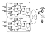
- the sensor-Net system is made up of a management server 4 equipped with a middleware for controlling the sensor nodes and managing the association of nodes, plural gateway nodes 1 , plural router nodes 2 , and plural sensor nodes.
- the management server 4 , the router node 2 , and sensor node 3 are connected by wireless communication, establishing a personal area network (PAN).
- PAN personal area network
- the gateway node 1 and the management server 4 may be connected by an Ethernet or a USB (universal serial bus).
- FIG. 2 there is shown a schematic diagram illustrating an exemplary hardware configuration in the sensor node 3 used in the sensor-Net system shown in FIG. 1 .
- the sensor node 3 includes an RF transceiver 201 for wireless transmission and reception, a display 202 , a button 203 , a sensor(s) 204 , a microprocessor 205 which is the processing unit, a real-time clock 206 which maintains the absolute time, a volatile memory 207 , nonvolatile memory 208 , and read-only memory 209 which serve as the storage unit, and a battery 210 for supplying power to the components of the node.
- the sensor node 3 may be one of either two states for a given period of time, namely sleep mode in which all hardware is powered off except for the real-time clock 206 , and an operation mode in which all circuits are powered on.
- sleep mode in which all hardware is powered off except for the real-time clock 206
- operation mode in which all circuits are powered on.
- the sensor node 3 senses using a variety of sensors 204 .
- the sensed information is put into packets by the microprocessor 205 along with the time information of the real-time clock 206 , is sent via a wireless means to the gateway node and to the router node from the RF transceiver 201 as well as is stored in the nonvolatile memory 208 .
- the button 203 is an input device for accepting the operation by the user. With a specific sequence of button a specific operation of the sensor node 3 may be invoked or the operation parameter may be set.
- the display 202 is an output device for displaying information to the user. For example, if the sensor node 3 is placed indoor or outdoor for use as environment measurement, the latest measurement value measured by the sensor(s) 204 may be displayed thereon. To save power, it is preferable that the display normally is turned off but indicates the latest measurement value only when a specific combination of button is pressed. If the sensor node 3 is a name plate type, or watch type portable sensor node, it usually displays time but when it receives a text message from the management server 4 it may display the message or when it receives a voice message it may display the information of reception. The node may display a hierarchy menu in association with the button sequence by the user. By pressing button in accordance with the menu, the application user or system manager may set the operation parameters of the sensor node, or confirm the error information when the communication is failed.
- the router node includes an RF transceiver 301 for the wireless transmission and reception, a display 302 , a button 303 , a sensor(s) 304 , a microprocessor 305 , a real time clock 306 which maintains the absolute time, a volatile memory 307 , a nonvolatile memory 308 , and a read only memory 309 .
- the router node uses the time configuration managing table 311 stored in the volatile memory 307 to manage the path to the sibling sensor nodes.
- the command distributed by the wireless communication from the gateway node to the sensor nodes is received by the RF transceiver 301 , and routes the command to the sensor nodes present in the table time configuration managing table 311 . Also it receives the sensing information transmitted by the wireless communication from a sensor node to transmit thus received sensing information to the gateway node by the wireless communication.
- the router RT 1 is required to always wait for the data from the sensor node or the gateway node, but does not know when the data is sent, so that it operates by the external power instead of a battery unlike the sensor node.
- the power supplied through the power line is rectified by a power supply circuit 310 to provide to the components.
- the microprocessor 305 of the router node 2 is not required to be put into the sleep mode, unlike the sensor node 3 .
- the interrupt controller and timer which are not shown in the figure, thereby have the function used in the limit of generic data transmission and reception algorithm.
- FIG. 4 there is shown an exemplary hardware arrangement of the gateway node 1 used in the sensor-Net system shown in FIG. 1 .
- the gateway node has the similar components to the router node 2 except for having a LAN interface (LAN I/F) 412 for communicating with the middleware server 4 through an IP network, the detailed description thereof will be omitted.
- LAN I/F LAN interface
- the reference numbers 401 to 410 correspond to the reference numbers 301 to 310 in FIG. 3 .
- the volatile memory 407 there is stored a binding table 411 as will be described later.
- FIG. 5 there is shown a schematic block diagram illustrating an exemplary hardware arrangement of the sensor-Net system management server 4 shown in FIG. 1 .
- the sensor-Net management server 4 includes a processor (CPU) 501 , a communication unit 502 , a power supply 503 , a hard disk drive 504 , a keyboard 505 which is an input device for a user to input a command, a display 506 , and a memory 507 .
- the sensor-Net management server 4 receives through the communication unit 502 the data collected by the gateway node 1 from the sensor node 1 through the router node 2 , and transmits the commands to the gateway node 1 .
- the CPU 501 reads such programs as middleware stored in the memory 507 , processes, by the instruction of the program, such data as the observation values obtained through the communication unit 502 , stores the data to the hard disk drive 504 , or displays the data onto the display 506 . A more specific example of processing and display executed by the management server 4 will be described in greater details later.
- the CPU 501 interprets the user command input from the keyboard 505 to transfer through the communication unit 502 to the gateway node 1 .
- FIG. 6 there is shown a schematic block diagram illustrating the functionality of the sensor node 3 in the preferred embodiment.
- the function of the sensor node 3 includes, the real-time clock 206 for managing the time, a main unit 601 for storing the observation value and for managing the event publishing and polling publishing, an observation unit 602 for using the sensor(s) for the observation, an event publisher unit 604 for publishing an event such as the observation value, a polling publisher unit 605 for publishing to the router node 2 or to the gateway node 1 the polling to confirm whether a command is present or not, a transmitter unit 606 for transmitting an event or a polling, an observation value storage management unit (event storage unit) 607 for managing the storage of observation values, an observation value storage unit 603 for storing the observation values and managing by the observation value table 613 , an observation value time stamp correction unit 608 for correcting the time stamp of the observation values which has the time unconfirmed flag set to ON (a flag which means the observation time is unconfirmed) in the observation value table 613 , an RTC setting unit 609 for setting and correcting the real time clock, a receiver unit
- the observation value table 613 stored in the observation value storage unit 603 stores the sequence number 614 which is the serial number of the observation values, a time unconfirmed flag 615 which stores whether the time is confirmed or unconfirmed in an observation value, an observation value 616 , and the time of the observation value 617 .
- the observation value storage unit 603 is formed on the nonvolatile memory 203 .
- the transmitter unit 606 and the receiver unit 610 shown in FIG. 6 correspond to the RF transceiver 201 shown in FIG. 2 .
- Other components including the main unit 601 , the observation unit 602 , the event publisher unit 604 to the RTC setting unit 609 , the command analyzer unit 611 , the other commands processing unit 612 are program functions executed by the microprocessor 205 of FIG. 2 , these programs are stored in general on the storage unit such as the read-only memory 209 .
- FIG. 7 there is shown a schematic block diagram illustrating the function of the router node 2 in accordance with the preferred embodiment of the present invention.
- the router node 2 includes a command receiver unit 701 , a time configuration processing unit 1301 , and a command transmission processing unit 1401 , a command request receiver unit 707 , a command publisher unit 708 , and a real-time clock 306 .
- the time configuration processing unit 1301 includes a time configuration manager unit 703 and a time configuration manager unit 702 .
- the volatile memory 307 shown in FIG. 3 has a time configuration managing table 311 . In the time configuration managing table 311 the sensor node ID 709 each allocated for each sensor node, and a time configuration flag 710 for determining whether or not the sensor node in the node ID 709 has the time configured.
- the router node 2 receives the command transmitted from the management server 4 at the command receiver unit 701 .
- the time setting unit 702 for setting or correcting the time of the real time clock 306 and the time configuration manager unit 703 for setting On the time configuration flag of the sensor node registered in the time configuration managing table 311 will work.
- the polling command from the sensor node 3 is received by the command request receiver unit 707 .
- the time configuration status checking unit 706 will check to see the time configuration flag 710 of the sensor node when receiving the polling from the sensor node in the time configuration managing table 311 .
- the time obtaining unit 705 obtains the time from the real time clock 306 .
- the command publisher unit 708 publishes a command to the sensor node 3 .
- FIG. 8 there is a schematic block diagram illustrating the function of the gateway node 1 in accordance with the preferred embodiment of the present invention.
- the function of the gateway node 1 includes a wired communication unit 801 for communicating with the management server 4 , a command processing unit 805 for processing commands from the management server 4 , a time configuration unit 806 for setting the real time clock 806 in the gateway node 1 , a setTime processing unit 807 for referring the binding table 411 to process the setTime command when receiving the setTime command, a command publisher 804 for publishing the command to the sibling router node 2 or to the sibling sensor node 3 present in the binding table 411 , a wireless communication unit 803 for wireless communication with the router node 2 and the sensor node 3 , and an event processing unit 802 for processing events received from the router node 2 or the sensor node 3 .
- a node category recorder 809 for storing the category by determining whether the recorded node is a router or a sensor node, and a node ID 810 each provided for each node are stored.
- FIG. 9 there is shown a schematic block diagram illustrating the network management function of the sensor-Net management server 4 in accordance with the preferred embodiment of the present invention.
- the network management function of the management server 4 includes a time configuration management unit 902 , an external request receiver unit 901 for receiving a user command 910 and for transferring to the time configuration management unit 902 or to the action manager 906 and transmitting the response to the external entity, a timer 904 for synchronizing with a reference time 903 such as NTP (network time protocol) to issue a setTime command at a given time, a setTime command publisher 905 for issuing the setTime command, a sensor-Net communication unit 907 (Profiled adapter & ZigBee adapter) which corresponds to the communication unit 502 for communicating with the gateway node 1 , an event publisher 908 for transferring the event from the gateway node 1 , or the router node 2 , or the sensor node 3 , and an observation value storage unit 909 for storing the observation value of the sensor node 3 .
- a reference time 903 such as NTP (network time protocol) to issue a setTime command at a given time
- the observation value storage unit 909 is formed on the storage unit such as the hard disk drive 504 or the memory 507 in FIG. 5 , and the function units except for the observation value storage unit 909 and the sensor-Net communication unit 907 are configured as the processing function of the CPU 501 shown in FIG. 5 .
- FIG. 10 there is shown a time configuration sequence diagram between the router node 2 and the sensor node 3 (sensor # 1 ) when the sensor node 3 (sensor # 1 ) is intermittently operating at the interval of 10 minutes. Any other operations except for the time configuration such as observation are omitted in this figure because FIG. 10 only illustrates the time configuration sequence.
- the sensor # 1 When the sensor # 1 returns from the sleep mode 1012 and enters into the active mode 1006 , the sensor # 1 will poll 1007 the parent router node 2 . At this time the router node 2 has not received yet any setTime, and the time configuration flag 710 in the time configuration managing table 311 is OFF (displayed as white in the figure). The router node transmits a no command present 1008 as the response to the polling 1007 . The sensor # 1 upon reception of the response immediately moves to the sleep mode 1013 .
- the duration of the active period 1006 may be in the range from a few milliseconds to tens milliseconds, including the polling and the reception of the response.
- the router node 2 which receives the reference time 1001 issued by the management server 4 , will set or correct the real time clock 306 of the router itself, then set to ON the time configuration flag 710 of the sibling sensor nodes 3 registered in the time configuration managing table 311 (displayed as gray in the figure).
- the router node 2 when receiving a command request as polling 1007 from the sibling sensor node (sensor # 1 ) which is registered in the time configuration managing table 311 , confirms the time configuration flag 710 , and if the flag is ON, then it will respond with a command present 1009 , obtains the time from the real time clock 306 of the router itself (step S 1006 ), transfers the time (t 2 ) to the sensor # 1 as the setTime command 1010 . Thereafter the sensor node 3 turns OFF the time configuration flag 710 of the sensor node.
- the sensor # 1 upon reception of the response to the command present 1009 , will wait for a while in a stand-by state, then will correct, based on the received time (t 2 ), the time of the real-time clock 206 of the sensor node itself.
- the active period 1014 of the sensor # 1 at this time may be longer than the active period 1006 because the sensor node receives the setTime command to reconfigure the time, however the period may be in the range from 10 milliseconds to 50 milliseconds on total, which is an instant when compared with the duration of sleep period which is 10 minutes.
- FIG. 11 there is shown a time configuration sequence diagram between the management server 4 and the gateway node 1 and the router node 2 and two sensor nodes 3 .
- the time configuration sequence will be similar even if there are more than three sensor nodes 3 .
- the sensor # 1 which returns from the sleep period 1106 and enters into the active period 1107 , will poll 1007 to the parent router node 2 . At this time the router node 2 has not received yet any setTime command, and because the time configuration flags 710 in the time configuration management table 1111 are all OFF, the router node 2 will transmit a no command present 1008 as the response to the polling 1007 to the sensor # 1 .
- the sensor # 1 which has received the response thereto, will immediately enter into the sleep mode 1108 .
- the duration of the active period 1107 may be in the range from a few milliseconds to tens milliseconds, including the polling and the reception of the response thereto.
- a sensor # 2 in a similar manner, which returns from the sleep mode and enters into the active period 1111 , will send a polling 1103 to the parent router node 2 .
- the router node will respond the no command present 1104 to the sensor as was done in case of the sensor # 1 , and the sensor # 2 , upon reception of the response thereto, will immediately enter into the sleep mode 1112 .
- the management server 4 is synchronized with a reference time by NTP.
- the management server 4 sends a time (t 1 ) as the setTime command to the gateway node 1 at a regular basis, or at the time specified by the user.
- the gateway node 1 uses thus received time (t 1 ) to set or correct the real time clock 406 of the station itself ( 1101 ).
- the gateway node 1 will confirm the binding table 808 , which is a management table of the nodes reachable from the gateway node, at the same time as the real time clock configuration 1101 , and transmits the time (t 1 ) obtained from the management server 4 as the setTime command to the sibling routers registered in the table.
- the time is synchronized by transmitting the time (t 1 ) to all routers in a similar manner if there are plural routers registered in the table.
- the router node 2 will set or correct the real time clock 306 in the router itself based on the time (t 1 ) received from the gateway node ( 1301 ), then set to ON the time configuration flag 710 to all sibling sensor nodes registered in the time configuration managing table 311 .
- the sensor node 3 a (sensor # 1 ), immediately after returned from sleep period 1108 , will perform the observation ( 1102 ), then send a polling 1107 as the command request to the router node 2 .
- the parent router node 2 of the sensor # 1 upon reception of the polling 1107 as the command request from any one of the sibling sensor nodes registered in the time configuration managing table 311 , will confirm the time configuration flag 710 of the sensor node, and respond with a command present 1009 if the flag is ON, and obtains (S 1406 ) the time from the real time clock 306 of the router node 2 itself to send the time (t 2 ) as the setTime command. Thereafter, when it receives an Ack which is the response to the setTime command from the sensor # 1 , the router turns OFF the time configuration flag 710 of the sensor node.
- the active period 1109 of the sensor # 1 will be longer than the active period 1107 , because the sensor # 1 receives the setTime command and set the time, however the period may be in the range from 10 milliseconds to 50 milliseconds, including the processing time of polling, time configuration reception, sending an observed event ( 1105 ), and receiving a reply (Ack), so the active period may be an instant when compared with 10 minutes of the duration of the sleep period.
- the sensor node 3 b upon reception of the reply to the command present 1009 , will wait for a while in a stand-by state, then correct the time in the real-time clock 206 of the sensor node itself based on the received time (t 2 ).
- the sensor # 1 obtains the time from its real time clock 206 and attaches it to the observation value for sending to the router node 2 as an observed event ( 1105 ).
- the sensor node 3 b (sensor # 2 ) will perform a similar sequence as the time configuration sequence of the sensor # 1 .
- FIG. 12 there is shown a PAD diagram of the operation of the router node 2 in accordance with the preferred embodiment of the present invention.
- the router node 2 will perform an event transfer 1203 for transferring to the gateway node 1 if the received data is an event such as the observation value from the sensor node 3 , a command transmission 1401 in case of polling from the sensor node 3 , a time configuration processing 1301 when having received a setTime command from the gateway node 1 , and a command storage 1204 when receiving any command other than the time configuration.
- an event transfer 1203 for transferring to the gateway node 1 if the received data is an event such as the observation value from the sensor node 3 , a command transmission 1401 in case of polling from the sensor node 3 , a time configuration processing 1301 when having received a setTime command from the gateway node 1 , and a command storage 1204 when receiving any command other than the time configuration.
- FIG. 13 there is shown a time configuration sequence diagram in the time configuration processing unit 1301 .
- the router node 2 receives in the command receiver unit 701 a setTime command through the gateway node 1 from the management server 4 (step S 1302 ).
- the time configuration unit 702 will set the real time clock 306 of the router itself to the time described in the setTime command (step S 1303 ).
- the time configuration manager unit 703 turns ON all time configuration flags 710 of the sibling nodes which are managed in the time configuration managing table 311 (step S 1304 ), and the process terminates (step S 1305 ).
- FIG. 14 there is shown a command transmission sequence of the router node 2 .
- the router node 2 upon reception of a polling, the command request from the sensor node 3 , at the command request receiver unit 707 , will determine whether there is a stored command (step S 1402 ), and if there is a command then it will send a command present to the sensor node (step S 1404 ).
- the time configuration status checking unit 706 will determine the time configuration flag 710 of the sensor node in the time configuration managing table 311 (step S 1405 ), and if the flag is ON then the time obtaining unit 705 will obtain the current time from the real time clock 306 of the router node 2 (step S 1406 ), will send a setTime command from the command publisher unit 708 (step S 1407 ), then will turn off the time configuration flag of the sensor node (step S 1408 ), and will check to see if there is still another command stored therein (step S 1402 ). If the time configuration flag 710 is OFF, then it will send another stored command (S 1409 ), and will check to see if there is still another command stored therein (S 1402 ). If there is no more command stored for the sensor node, it will send no command present to the sensor node (step S 1403 ), and the process terminates (S 1410 ).
- FIG. 15 there is shown a flow chart of the operation of the sensor node 3 in accordance with the preferred embodiment of the present invention.
- the sensor node 3 intermittently operates, in which it repeats the activation to enter into the active state (S 1501 ) and the deactivation to enter into the sleep state (S 1514 ) at a regular interval. For the activation interval, an independent period may be set for any sensors if a sensor node is equipped with plural sensors 204 .
- the sensor node 3 When the sensor node 3 is activated, it will observe (S 1502 ) in the observation unit 602 as shown in FIG. 6 , issue a polling from the polling publisher unit 605 , then send the polling from the transmitter unit 606 to the parent router node 2 (S 1503 ).
- the command analyzer unit 611 will determine whether the command received is a setTime command or not (S 1506 ), if it is a setTime command then the RTC setting unit 609 will set or correct its real-time clock 206 (S 1507 ), then the observation value time stamp correction unit 608 will correct the time stamp of any observation values with the time unconfigured flag being ON, from within any previous observation values in the observation value table 613 (step S 1508 ). If the received command is not a setTime command then the other commands processing unit 612 will process the command (S 1509 ).
- the sensor node 3 After finishing the processing of the command, the sensor node 3 will determine whether it has already time configured (S 1510 ), if the time is configured then the event publisher unit 604 will issue an event with the current time appended as time stamp to the observation value, then the observation event will be sent to the parent router node 2 or to the parent gateway node 1 from the transmitter unit 606 (step S 1512 ). If the sensor node 3 is not yet time configured then the observation value will not be sent, however a HeartBeat event will be sent to the parent router node 2 or to the parent gateway node 1 in order to notify of the alive sensor node 3 (S 1511 ).
- the sensor node 3 After the transmission of the event, the sensor node 3 stores the observation value into the memory along with the sequence number, time unconfigured flag, and the time of real time clock (S 1513 ), and will enter into the sleep mode (step S 1514 ).
- FIGS. 16A and 16B there are shown schematic diagrams illustrating the time stamp correction (S 1508 ) of the observation value table 613 in the sensor node 3 shown in FIG. 15 .
- FIGS. 16A and 16B illustrate examples of data in the observation value table 613 in the sensor node 3 before and after correction of the time stamp, respectively.
- the sensor node 3 calculates the difference between the time stamp of the latest observation value and the time in the setTime command, at the time when it receives the setTime command from its parent router node 2 or the parent gateway node 1 and configures the time. Then by referring to the observation value table 613 of the sensor node, it will correct the time by adding the difference to the time stamp of the observation value with the time unconfigured flag being ON, then will turn OFF the time unconfigured flag to correct the time stamp of the observation value.
- the difference as have been described above may also be the difference between the time in the setTime command and the time before correcting the real-time clock 206 at the time of reception of the setTime command.
- the correction timing of the time stamp may be at any given time after the calculation of the difference.
- the observation event including the observation value data, sent from the transmitter unit 606 of the sensor node 3 to the parent router node 2 or to the parent gateway node 1 , will be all transferred to the management server 4 , stored in the observation value storage unit 909 in the storage unit of FIG. 5 or FIG. 9 , then will be processed appropriately as an example will be described later.
- a sensor-Net system which adopts another time synchronization method as shown in FIG. 17 will be described in greater details herein below as second preferred embodiment of the present invention.
- FIG. 17 there is shown a schematic diagram illustrating a sensor node initiative time configuration sequence which implements the time synchronization at the timing requested by a sensor node 3 , when the sensor node 3 (sensor) is connected directly to the gateway node 1 .
- the sensor node 3 sends a time configuration request ( 1701 ) to the gateway node 1 when connected to the gateway node 1 or at a regular basis.
- the gateway node 1 will send an Ack 1702 to the time configuration request while obtaining the reference time information ( 1703 ).
- the time required for the gateway node to obtain the time information after having received the time configuration request may be approximately one millisecond.
- the sensor node 3 invokes its internal timer at the time when it receives the Ack to the time configuration request ( 1704 ). Since the processing time required for the sensor node 3 to receive the acknowledgement after the gateway node 1 sends the acknowledgement is approximately one millisecond, this time may be considered to be approximately the same duration as the time required for the gateway node 1 to receive the time configuration request and to set the time.
- the time as have been described above is the timer built-in to the microprocessor within the sensor node 3 .
- the time accuracy is 1 ppm, so the error for setting time may be neglected.
- some processing than the time configuration by interrupt are needed, so that the time accuracy is 10 milliseconds.
- the microprocessor In the sleep period the microprocessor is sleeping in the low power mode while the timer operation continues to be executed.
- the gateway node 1 When the sensor node 3 transmits a polling command, the command request, at the time when it is reactivated for the next time ( 1704 ), the gateway node 1 in turn transmits to the sensor node 3 the time obtained as second setTime command for the reply thereto ( 1705 ).
- the sensor node 3 stops the timer at the time when it receives the second setTime command from the gateway node 1 ( 1708 ), it sets its own real-time clock 206 as current time by the time adding the time received concurrently with the second setTime command with the time measured by the timer ( 1709 ).
- the sensor nodes 3 With the time synchronized with the gateway node 1 , in a similar manner to FIG. 11 in the first preferred embodiment, will send the stored observation values to the gateway node 1 directly. The detailed description will be omitted however to avoid the repetition.
- FIGS. 18A to 18C there are shown an applied system function for determining the influence between plural persons each wearing a sensor node by using the sensor-Net system based on the time synchronization scheme as described above and by using the observation value data stored in the observation value storage unit 909 of the management server 4 .
- FIG. 18A assuming that more than two persons 1801 and 1802 have or wear the sensor nodes 3 a and 3 b .
- a person 1802 is considered to be affected by another person 1801 if during a conversation between the person 1801 and the person 1802 , the person acts a gesture such as the person nods for expressing the accordance with an important speech of the observation value waveform 1801 , or the person 1802 gives a grunt or writes down the phrase in accordance with the speech of the person 1801 .
- Such action or speech may not be randomly present, rather as shown in block 1803 of FIG. 18C , it appears on the observation value waveform of the acceleration or voice of the person 1802 after a delay less than a second from the observation of the speech or action by the observation value waveform of the acceleration or voice of the person 1801 .
- FIG. 19A , FIG. 19B , and FIG. 19C there are shown schematic diagrams illustrating the flow of process for executing the organization dynamics analysis by performing the process of determining the communication by means of the applied system.
- FIG. 19A , FIG. 19B , and FIG. 19C describe a sequential flow from obtaining the organization dynamics data by plural sensor nodes 3 to showing the connection between persons and the current organization evaluation (performance) as the organization activity.
- the organization dynamics data obtainment (BMA), the input of performance (BMP), the organization dynamics data collection (BMB), mutual data alignment (BMC), the correlation coefficient learning (BMD), organization activity analysis (BME), and the organization activity representation (BMF) are executed in an appropriate order.
- the sensor node 3 A (TRa) shown in FIG. 19C includes such sensors as an acceleration sensor (TRAC), an infrared transceiver (TRIR), and a microphone (TRMI), a microcomputer (not shown in the figure) and a wireless transmission function.
- the sensors detect a variety of physical quantities, and obtain the observation data indicating thus detected physical quantities.
- the acceleration sensor (TRAC) detects the acceleration of the sensor node 3 A (TRa), namely the acceleration of the person A (not shown in the figure) wearing the sensor node 3 A (TRa).
- the infrared transceiver detects the face-to-face status of the sensor node 3 A (TRa), namely the status in which the sensor node 3 A (TRa) is in face to another sensor node 3 .
- the fact that the sensor node 3 A (TRa) faces with another sensor node 3 indicates that the person A wearing the sensor node 3 A (TRa) is facing with another person wearing another sensor node 3 .
- the microphone (TRMI) detects the voice around the sensor node 3 A (TRa).
- the sensor node 3 A (TRa) may also have other sensors (such as including a temperature sensor, a luminance sensor, etc.).
- the applied system in this example includes plural sensor nodes 3 (more specifically the sensor node 3 A (TRa) to sensor node 3 J (TRj) of FIG. 19C ).
- These sensor nodes 3 are each worn by the respective person: for example, the sensor node 3 A (TRa) is worn by the person A, the sensor node 3 B (TRb) by the person B (not shown in the figure), and so on. This is for analyzing the connection among the persons wearing the sensor node and for displaying the performance of the organization.
- the sensor node 3 B (TRb) to sensor node 3 J (TRj) also include sensors, a microcomputer, and a wireless transmitter as similar to the sensor node 3 A (TRa).
- these sensor nodes are collectively referred to as sensor node 3 (TR) in case when the description applies to all of sensor node 3 A (TRa) to sensor node 3 J (TRj), and when there is no need to distinguish each sensor node 3 .
- Each sensor node 3 (TR) performs sensing by sensors all the time (or repeatedly at a short interval). Then each sensor node 3 (TR) transmits the obtained data (sensing data) via the wireless communication at a given interval.
- the interval of transmission of data may be the same as the sensing interval, or may be a larger interval than the sensing interval.
- the data to be sent at that time includes the time of sensing, and the intrinsic ID of the sensor node 3 (TR).
- the wireless transmission of the data at once is for the purpose of maintaining the extended life of the sensor node 3 (TR) as long as possible while being worn by a person, by saving the consumption of power used for the transmission.
- the same sensing interval is set in all of the sensor nodes 3 (TR) for the purpose of the following analysis.
- the performance input (BMP) shown in FIG. 19C is the process of inputting the value indicating the performance.
- the performance herein is an objective or subjective evaluation determined based on some sort of reference. For example, the person wearing the sensor node 3 (TR) inputs at a predetermined timing a subjective evaluation (performance) value based on some sort of reference, such as the achievement of the work at that time, the contribution and satisfaction to the organization, and so on.
- the predetermined timing herein may be once for a few hours, once a day, or each time an event such as a conference is over.
- the person wearing the sensor node 3 (TR) operates the sensor node 3 (TR) or operates a personal computer (PC) such as a client (CL) to input the performance value. Or the values written by hand may be input at once later by using a PC.
- the input performance value is used for learning the correlation index. Once a sufficient quantity of performance values is obtained for learning at a given level, there is no need of input further values.
- the performance with respect to the organization may also be calculated from the performance of individuals.
- the objective data including such as the sale and cost, as well as the data already digitized such as the result of a questionnaire of clients may also be input as performance at a regular interval. If the numerical data can be automatically obtained such as the error rate in the production management, thus obtained numeric values may be automatically input as the performance value.
- the data transmitted via the wireless communication from the sensor node 3 (TR) is gathered by the organization dynamics data collection (BMB) shown in FIG. 19C , and stored in a database.
- BMB organization dynamics data collection
- a data table is created for each sensor node 3 (TR), or for each person wearing a sensor node 3 (TR).
- the collected data is classified based on the intrinsic ID, and is stored in the data table in the order of sensed time.
- the data table A (DTBa) in the figure describes a simplified version of an exemplary data table.
- the performance value input in the performance input (BMP) is stored in the performance database (PDB) along with the time information.
- the data table database gathered in the organization dynamics data collection (BMB) is stored sequentially in the storage unit shown in FIG. 5 .
- the data with respect to these two persons based on the time information is aligned.
- the aligned data is stored in the table.
- the data having the same time is stored in the same record (row).
- the data having the same time indicates two items of data including the physical quantities detected by two sensor nodes 3 (TR) at the same time. If the data with respect to these two persons does not include the data of the same time, the data of the nearest time may be used approximately as the data of the same time. In this case the data items of the nearest time are stored in the single same record. It is preferable that the time of the data items stored in the same record should be aligned to the mean value of the nearest time. These data items may be stored so as to be capable of comparing chronologically the data, and may not be necessarily in the table.
- connection table (CTBab) shown in FIG. 19C is a simplified expression of the exemplary table connecting the data table A (DTBa) with the data table B (DTBb). It should be noted here that the details of the data table B (DTBb) is not shown in the figure.
- the connection table (CTBab) includes the data of acceleration, infrared, as well as voice. However the connection table for each kind of data, for example the connection table including only the acceleration data, or the connection table including only the voice data may also be created.
- the learning of the correlation index (BMD) is executed for calculating the relationship from the organization dynamics data or for predicting the performance (see FIG. 19B ).
- the correlation index learning is a process for determining the communication. For example, there are cases in which someone communicates with gestures such as nodding for an important speech of the other person during conversation. The action is not at random, but is taken at a given timing. The timing here is just after the speech or gesture of the other person.
- the communication between these individuals may be determined so that it is clear that the observation value data synchronized between the sensor nodes 3 is important.
- One speaker 1801 wears the sensor node 3 a (sensor # 1 ) and the other speaker 1802 wears the sensor node 3 b (sensor # 2 ).
- the gateway node 1 sends a setTime command to these two sensor nodes to synchronize with error less than for example 10 milliseconds.
- FIGS. 18A to 18C there are only two speakers, however there may be plural speakers. In such a case some combinations covering all from within all the speakers are specified and the process is executed for each combination.
- the process flow for the correlation learning by using the system shown in FIGS. 18A to 18C is shown in the correlation index learning (BMD) of FIG. 19B .
- the process is more effective if the correlation index is updated by recalculating regularly based on the new data.
- the correlation index is calculated from the acceleration data.
- the correlation index can be calculated in a similar procedure by using the time-series data such as voice data instead of the acceleration data.
- the correlation index learning (BMD) shown in FIG. 19B is executed in the management server 4 described with reference to FIG. 5 and FIG. 9 , more specifically in the CPU 501 thereof.
- the correlation index learning (BMD) may also be executed by any other device than the management server 4 .
- the management server 4 will set the width T of data used for calculation of the correlation index to a range from a few days to several weeks and will select the data within the range.
- the acceleration frequency calculation (BMDA) is a process for determining the frequency from the acceleration data aligned in the time series.
- the frequency is defined as the number of oscillation of a wave in one second, this index indicates the intensity of the oscillation.
- BMDA acceleration frequency calculation
- the frequency may be determined positively by using the Fourier Transform, in the present embodiment the zero-cross data is used instead, which correspond to the frequency, in order to simplify the calculation.
- the zero-cross data is the number of times that the values in the time-series data for a predetermined period of time become zero, more precisely, the count of the number of times that the time-series data varies from a positive value to a negative value or from a negative value to a positive value. For example, when determining one cycle as the value of the acceleration have changed from the positive side to the negative side, then the value again have changed from the negative side to the positive side, the number of oscillations for one second can be calculated from the number of times of counted zero-crossing. The number of oscillation thus calculated for one second may be used as an approximated frequency of the acceleration.
- the sensor node 3 (TR) of the present embodiment has a triaxial acceleration sensor, one single zero-crossing value may be calculated by adding the zero-crossing values in the triaxial directions of the same period of time. This allows detecting the fine motion of pendulum in the left-right and front-back direction to use as the index indicative of the intensity of the oscillation.
- a “predetermined period of time” for counting the zero-crossing data may be set to a value larger than the interval of contiguous data (i.e., the original sensing interval), in a range of seconds or minutes.
- the observation values used for the analysis are preferably of the same time width in the speaker 1801 and in the speaker 1802 , for example the values in a day (24 hours).
- the observation values are further preferably continuously or periodically substituted, and when an observation value is missing a value indicative of the absence such as NULL may be substituted therewith.
- Framing is a process for splitting the time width of the observation values into plural uniform widths. For example, in case of the observation value time width for a day (24 hours), a frame of one hour or so is preferable. The size of the width split is referred to as frame length. As there are plural sensor signals in the input sensor signal, the timing and the width of splitting into a frame (frame length) is always the same. In addition, the span between two frames may not be necessarily needed to set to the same time of frame split. For example, in case of six minutes of interval between two frames (frame interval), the interval of 6 minutes indicates that the interval from the start time of the first frame to the start time of the next frame is six minutes.
- the cross-correlation calculation (BMDC) is determined for each frame of the input observation values.
- the cross-correlation indicates the relationship of two time varied sensor signals.
- the cross correlation index between two observation values may be defined as follows:
- a x A ⁇ mean value of the feature x 1 of the person A in the range of time from 0 to T
- the observation values included in the frame are checked to see for improving the precision of the cross-correlation index. This is done by counting the number of two sensor signals which are not defected in the same period of time used for the process of the cross-correlation index, determining the rate of the defects, then skipping the cross-correlation index process for the frames which has a high defect rate.
- the threshold of the defect rate may be specified separately.
- the look down process is performed by determining the mean of the cross-correlation index determined for each frame in the input observation values in order to determine the correlation matrix (BMDE).
- the correlation matrix (BMDE) is used for predicting six performances from the acceleration data.
- the organization activity analysis (BME) shown in FIG. 19A is a process for determining the connection between two individuals from the acceleration, voice, face-to-face data with respect to two given individuals in the connection table, and for calculating the performance of the organization. This process also is performed by the management server 4 , more specifically by the CPU 501 .
- the organizational performance is predicted and presented to users in real-time basis while collecting data, to for example prompt so as to change the behavior to a better direction if the prediction is worse. Briefly the feedback may be possible for a shorter cycle.
- the acceleration frequency calculation (EA 12 ), the personal feature extraction (EA 13 ), the cross-correlation calculation between individuals (EA 14 ), and the organizational feature calculation (EA 15 ) use the similar procedure to the acceleration frequency calculation (BMDA), the personal feature extraction (BMDB), the cross-correlation calculation (BMDC) and the organizational feature calculation (BMDD) in the correlation index learning (BMD), and the detailed description will be omitted.
- the organizational features (x 1 , . . . , xm) will be calculated.
- the management server 4 then obtains the organizational features (x 1 , . . . , xm) calculated in step EA 15 and the correlational index (A 1 , . . . , A 6 ) with respect to the performances calculated by the correlation index learning (BMD) (step EA 16 ), then uses these values to calculate the index of performances, as follows:
- This value indicates the predictive value of the organization performance (EA 17 ).
- the latest values of six indices indicative of the organization performances are balance displayed. Further, the history of an index value is displayed in a time-series graph as the index prediction history.
- the distance between the given individuals which is determined based on the cross-correlational values between the individuals (EK 41 ) may be used for determining the parameters for indicating the organization structure (organizational structure parameters).
- the distance between individuals is an index indicative of the connection between these individuals, rather than the geographical distance. For example, the stronger the interpersonal relationship is (for example, the stronger the cross-correlation between the individuals), the nearer the interpersonal distance.
- the grouping is a process for creating the combinations of individuals in an intimate relation, such as creating one group of at least two individuals A and B who are specifically intimate, and another group of at least two individuals C and D who are also specifically intimate, then a large group of the combination of these individuals A, B, C, and D, and so on.
- the infrared data includes the information indicating when and who meets someone.
- the management server 4 uses the infrared data to analyze the face-to-face record (EI 22 ).
- the management server 4 will then determine the parameter for displaying the organization structure based on the face-to-face history (EK 43 ).
- the management server 4 may calculate the distance between given individuals from the face-to-face history, in order to determine the parameters based on the distance. For example, the distance may be calculated such that the distance between the individuals becomes shorter (in other words the stronger relationship) if the number of times of meeting two individuals within a predetermined period of time is as much frequent.
- the management server 4 may determine the parameters so as to reflect the sum of total number of the face-to-face meeting of a person to the size of a node, the number of times of the short-term meeting of individuals to the distance between nodes, and the number of times of the long-term meeting between the given individuals to the width of the link.
- the node herein is a shape displayed for indicating an individual on the display (CLOD) of a client (CL).
- the link herein is a line displayed for connecting two nodes. The person who has met the largest number of times with someone who could be anybody will be displayed as the largest node. The combination of persons who have been met frequently recently is displayed by two closer nodes. The combination of persons who have been met for a long period of time will be displayed by two nodes connected by a thick link.
- the management server 4 may also reflect the property information of a user who wears the sensor node 3 to the display of the organization structure. For example, the color of node indicative of a person may be defined based on the age of the person, the shape of the node indicative of a person may be defined based on his/her post.
- the speech feature may be extracted (EV 33 ) by extracting the voice feature from the voice data (EV 32 ) and by analyzing the feature in combination with the face-to-face data.
- the speech feature is the quantity indicative of the voice tone in the conversation, the rhythm of the conversation, or the balance of speech.
- the balance of speech is the quantity indicating whether one of two persons speaks in the one-sided manner, or whether both of them speak evenly, and the quantity is extracted based on the voice of two individuals.
- the management server 4 may determine the display parameter such that the speech balance is reflected to the angle between nodes. More specifically, for example, when two individuals speak evenly, the nodes indicative of these two individuals may be displayed horizontally. In case in which one of them speaks in one-way, the node indicative of the person who is speaking may be displayed above the other node indicative of the other person. If the tendency that one of them speaks in the one-way fashion is much intensive, the angle between the line connecting these nodes indicative of two persons and the reference line (in the organization structure display (FC 31 ) shown in FIG. 19A , the angle theta AB or theta CD) may be displayed larger.
- the reference line herein is the line set in the lateral direction of the display (i.e., in the horizontal direction). The reference line may or may not be displayed.
- the organization activity display is a process which creates, from the organization performance prediction and the organization structure parameters as calculated by the process as have been described above, the index balance indication (FA 11 ), index forecast record (FB 21 ), the representation of organization structure (FC 31 ) and the like, then displays on the display (CLOD) of the client (CL).
- the organization activity (FD 41 ) shown in FIG. 19A is an exemplary screen displayed on the display (CLOD) of the client (CL).
- the display period of time selected, and the units or plural members to be displayed are initially displayed.
- the unit herein is an organization composed of plural persons. All members belonging to one unit may be displayed, or plural members constituting a part of a unit may be displayed.
- the result of analysis based on the condition indicated by the period of time of display and the unit is displayed by three figures.
- the record of the forecast result of the performance in the “growth” is displayed as an example. This allows analyzing, by checking with the past action history, what kind of action of a member contributes to the growth of the organization, and additionally what is effective for the conversion from negative to positive result.
- the situation of a small group constituting the organization, the role substantially played by the persons in the organization, and the balance between given individuals may be visualized.
- the index balance indication (FA 11 ) indicates the balance configured for set six organization performance prediction. This allows assessing the advantages and the disadvantages of the current organization.
- FIG. 20 there is shown an applied system for detecting the focus 2001 of an earthquake by using the sensor-Net system.
- the grid search method (see for example non-patent reference document # 2 ) may be used.
- the location of the focus of earthquake with the precision of less than 100 meters by means of the grid search method more than three sensor nodes are required, each of which has an acceleration sensor or a vibration sensor, these sensor nodes are to be placed at the distance of 100 meters, and the time synchronization must be done at the precision of 20 milliseconds.
- FIG. 21 there is shown a system for observing the vibration of piping by using the sensor-Net system.
- the phase difference of the waveform 2102 conducted along with the piping 2101 is calculated by using the sensor-Net system, in order to detect the position of the pressure node and the pressure antinode. This allows specifying the location of generating the waveform or calculating the stress applied. To achieve this, it is needed to detect the phase difference of waveform conducting along with the piping at 200 Hz, requiring accordingly the time synchronization of the sensor nodes at the precision of a few milliseconds.
- FIG. 22 there is shown a schematic sequential diagram illustrating the time synchronization method in accordance with the third preferred embodiment of the present invention for decreasing the error of time when the sensor node 3 is connected to the gateway node 1 through the router node 2 in a multi-hop connection.
- the gateway node obtains the time t 1 from its own real time clock 406 ( 2201 ), and transmits t 1 to the router node.
- the router obtains the time t 3 from its own real time clock 306 ( 2204 ), and transmits the ⁇ T 1 and t 3 to the gateway node.
- ⁇ t is the delay at the time of setting the time in the gateway node and in the router. If the delay (t varies each time it is measured, the precision may be improved by calculating the mean of (t by measuring plural times. If a router is connected to another router, the delay may also be calculated between these routers.
- the base station gateway node obtains the time from its own real time clock 406 regularly or at the timing specified by the user ( 2207 ), to send a setTime command ( 2208 ).
- the current time t 5 obtained from its own real time clock 406 and the delay (t are sent at the same time in a setTime command.
- the router obtains the time t 6 from the real time clock of the router ( 2211 ) and sends the time t 6 and the delay (t as the setTime command ( 2212 ).
- the primary cause of the delay in this method is the processing time from the time when the firmware of the base station gateway node and the router obtain the time from the real time clock to the time when transmitting through their RF transceiver, and the processing time from the time when receiving at the RF transceiver to the time when obtaining the time from the real time clock, and in case in which no interrupt is included the delay will be at the level of tens milliseconds.
- the same circuit is used for the real time clock, the microprocessor, and the RF transceiver in the base station gateway node, the router, and the sensor node. Therefore the delay between the router and the sensor node can be considered to be almost the same as the delay between the base station gateway node and the router.
- the dispersion of the delay caused by the individual variability will be decreased by calculating the delay (t between the base station gateway node and all routers and by calculating the mean value.
- the error in the present method therefore is the error caused by the wireless retransmission, which is in the range of a few milliseconds to 10 milliseconds.
- the sensor-Net in a meshed type multi-hop has the advantage that the communication path can be freely selected.
- the time configuration is performed by avoiding the path having a larger delay to improve the time precision.
- the router stores the delay (t to calculate the variance ((t of the (t each time the router receives a setTime command.
- the ((t can be considered to as the communication cost.
- the time is set by using preferentially the path having a lower ((t in order to achieve a high precision time configuration.
- the sensor node may set the time while maintaining its intermittent operation, and the time is set only when the time in the router is synchronized with the reference time, the deviation of the time may be suppressed to the minimum while at the same time any waste waiting time is saved, as a result the power consumption can be lowered and more specifically when the sensor node is powered by a battery the life of the battery can be extended.
- the power consumption in the sensor-Net system may be saved, more specifically the battery life is extended if the sensor node is battery-operated.
Abstract
Description
xA(t): Value of the feature x1 at the time t of the person
mean value of the feature x1 of the person A in the range of time from 0 to T
p 1 =a 1 x 1 +a 2 x 2 + . . . +a m x m (2)
Claims (11)
Applications Claiming Priority (2)
| Application Number | Priority Date | Filing Date | Title |
|---|---|---|---|
| JP2007151866A JP4977534B2 (en) | 2007-06-07 | 2007-06-07 | Sensor network system and sensor node |
| JP2007-151866 | 2007-06-07 |
Publications (2)
| Publication Number | Publication Date |
|---|---|
| US20080307075A1 US20080307075A1 (en) | 2008-12-11 |
| US8438249B2 true US8438249B2 (en) | 2013-05-07 |
Family
ID=40096880
Family Applications (1)
| Application Number | Title | Priority Date | Filing Date |
|---|---|---|---|
| US12/068,704 Expired - Fee Related US8438249B2 (en) | 2007-06-07 | 2008-02-11 | Sensor-Net system and sensor node |
Country Status (3)
| Country | Link |
|---|---|
| US (1) | US8438249B2 (en) |
| JP (1) | JP4977534B2 (en) |
| CN (1) | CN101321180A (en) |
Cited By (4)
| Publication number | Priority date | Publication date | Assignee | Title |
|---|---|---|---|---|
| US20110131320A1 (en) * | 2007-12-17 | 2011-06-02 | Electronics And Telecommunications Research Institute | Apparatus and method of dynamically managing sensor module on sensor node in wireless sensor network |
| US20120170592A1 (en) * | 2010-07-08 | 2012-07-05 | Nec Europe Ltd. | Method of supporting power control in a communication network |
| US20150049774A1 (en) * | 2013-08-14 | 2015-02-19 | Hyundai Motor Company | Message processing method of gateway |
| US20220174376A1 (en) * | 2020-11-30 | 2022-06-02 | Nkia Co., Ltd. | Method and system for collecting sensor data using data channel and control channel |
Families Citing this family (45)
| Publication number | Priority date | Publication date | Assignee | Title |
|---|---|---|---|---|
| TWI387283B (en) * | 2008-04-25 | 2013-02-21 | Univ Nat Taiwan | Wireless smart controlling display panel |
| KR101179919B1 (en) * | 2008-05-30 | 2012-09-05 | 경북대학교 산학협력단 | Method for multipath source routing in sensor network |
| JP2010200203A (en) | 2009-02-27 | 2010-09-09 | Sony Corp | Method of remote control, and remote controller |
| JP5425614B2 (en) * | 2009-12-25 | 2014-02-26 | 三洋電機株式会社 | Time synchronization method, control system, and measuring apparatus |
| US8588192B2 (en) * | 2010-01-27 | 2013-11-19 | Infosys Limited | System and method for forming application dependent dynamic data packet in wireless sensor networks |
| US8509923B2 (en) * | 2010-06-30 | 2013-08-13 | Motorola Solutions, Inc. | Methods for managing power consumption in a sensor network |
| CN101945495B (en) * | 2010-08-13 | 2013-03-27 | 深圳市杰曼科技有限公司 | Difference frequency subnetwork communication system and method |
| CN102006670B (en) * | 2010-11-16 | 2013-06-12 | 西安电子科技大学 | Dynamic polling medium access control method of emergency response supported sensor network |
| CN102480465B (en) * | 2010-11-24 | 2014-10-22 | 富士通株式会社 | Self-adaptive adjusting method, sensor node and sensor network |
| JP5760579B2 (en) * | 2011-03-25 | 2015-08-12 | 株式会社大林組 | Wireless measurement control system and wireless measurement control method |
| FR2977419B1 (en) | 2011-06-28 | 2013-08-09 | Univ Paris Sud 11 | METHOD FOR EXTINTING ROUTERS IN A COMMUNICATIONS NETWORK AND ROUTER USING THE SAME |
| CN103096387B (en) * | 2011-10-28 | 2016-06-01 | 上海交通大学 | Based on the cognitive transmission method of high priority data classification in intelligent grid |
| US20130201316A1 (en) | 2012-01-09 | 2013-08-08 | May Patents Ltd. | System and method for server based control |
| NL2010179C2 (en) * | 2012-01-24 | 2013-08-14 | Innovius B V | DATA COLLECTION SYSTEM. |
| WO2013112050A1 (en) | 2012-01-24 | 2013-08-01 | Innovius B.V. | Data collecting system |
| NL2009316C2 (en) * | 2012-08-13 | 2014-02-18 | Innovius B V | DATA COLLECTION SYSTEM. |
| JP5849829B2 (en) * | 2012-03-30 | 2016-02-03 | 横河電機株式会社 | Wireless network system and time management device |
| JP5842715B2 (en) * | 2012-03-30 | 2016-01-13 | 富士通株式会社 | Intermittent reception control apparatus, intermittent reception control program, and intermittent reception control method |
| WO2014049633A1 (en) * | 2012-09-25 | 2014-04-03 | テルモ株式会社 | Biological information processing system, biological information measurement device, control device, method for controlling these, and storage medium |
| US10021189B2 (en) * | 2012-11-30 | 2018-07-10 | Valmet Automation Oy | Multi-channel sensor measurement method and system |
| CN103162816B (en) * | 2013-02-28 | 2015-06-24 | 唐山开诚电控设备集团有限公司 | Vibration monitoring method based on sensors |
| PE20160094A1 (en) * | 2013-07-10 | 2016-03-09 | Tlv Co Ltd | TIME SYNCHRONIZATION SYSTEM |
| DE102013213808A1 (en) * | 2013-07-15 | 2015-01-15 | Siemens Aktiengesellschaft | Vibration detection system, vehicle and vibration detection method |
| JP5991280B2 (en) * | 2013-07-25 | 2016-09-14 | 東芝三菱電機産業システム株式会社 | Sensor data collection system |
| JP6197881B2 (en) * | 2014-01-20 | 2017-09-20 | 富士通株式会社 | Communication node, system, and synchronization method |
| US9939838B1 (en) * | 2015-01-22 | 2018-04-10 | Invensense, Inc. | Systems and methods for time stamping sensor data |
| JP6409629B2 (en) * | 2015-03-11 | 2018-10-24 | オムロン株式会社 | Sensor system |
| JP6518103B2 (en) * | 2015-03-24 | 2019-05-22 | 学校法人 関西大学 | INFORMATION COLLECTING DEVICE, SENSOR NODE, AND INFORMATION COLLECTING SYSTEM COMPRISING THEM |
| US10311359B2 (en) * | 2016-03-09 | 2019-06-04 | Resolution Products, Inc. | Home wireless discovery |
| CN106341238A (en) * | 2016-08-10 | 2017-01-18 | 深圳奥尼电子股份有限公司 | Time control device and time control method |
| JP2018074242A (en) | 2016-10-25 | 2018-05-10 | 株式会社Where | beacon |
| JP6770499B2 (en) * | 2017-10-27 | 2020-10-14 | 日本電信電話株式会社 | Mobile sensor relay terminal and mobile sensor relay control method |
| US10841158B1 (en) * | 2017-10-31 | 2020-11-17 | Synapse Wireless, Inc. | Systems and methods for node maintenance in a network |
| US11323375B2 (en) * | 2017-12-27 | 2022-05-03 | Nec Corporation | Communication device, communication method, and computer readable medium |
| CN108494516B (en) * | 2018-01-19 | 2020-08-04 | 杭州博烁晟斐智能科技有限公司 | Distributed time service method for communication iron tower fault monitoring system |
| EP4250255A3 (en) * | 2018-02-02 | 2024-03-13 | Panasonic Intellectual Property Corporation of America | Information transmitting method, and client device |
| US10820292B1 (en) * | 2018-06-07 | 2020-10-27 | Lytx, Inc. | Time synchronization for sensor data recording devices |
| CN110072208A (en) * | 2019-05-16 | 2019-07-30 | 信息产业电子第十一设计研究院科技工程股份有限公司 | A kind of wireless intelligent network communication device based on photovoltaic power generation |
| US11508227B2 (en) | 2019-09-30 | 2022-11-22 | Resolution Products, Llc | Mobile device as a security system component |
| US11540354B2 (en) | 2019-09-30 | 2022-12-27 | Resolution Products, Llc | Gateway with backup power and communications system |
| JP7318557B2 (en) * | 2020-02-18 | 2023-08-01 | トヨタ自動車株式会社 | Communication system, control method and control program |
| JP7356781B2 (en) * | 2020-08-21 | 2023-10-05 | Kddi株式会社 | Program, device, and estimation method for estimating observation probability from observed values that may cause missing values |
| JP2022041553A (en) * | 2020-09-01 | 2022-03-11 | ヤマハ株式会社 | Communication control method |
| JP7412591B2 (en) * | 2020-11-06 | 2024-01-12 | 三菱電機株式会社 | vehicle control system |
| CN113315835A (en) * | 2021-05-27 | 2021-08-27 | 深圳市方腾网络技术有限公司 | Method for centralized control of Internet of things sensor |
Citations (9)
| Publication number | Priority date | Publication date | Assignee | Title |
|---|---|---|---|---|
| US20020038353A1 (en) * | 2000-09-22 | 2002-03-28 | Nec Corporation | Weather information delivery system and method thereof |
| US20060048019A1 (en) * | 2004-08-26 | 2006-03-02 | Canon Kabushiki Kaisha | Image input/output device, information processing method, storage medium stored with program readable by computer, and program |
| US20060064503A1 (en) * | 2003-09-25 | 2006-03-23 | Brown David W | Data routing systems and methods |
| US7035240B1 (en) * | 2000-12-27 | 2006-04-25 | Massachusetts Institute Of Technology | Method for low-energy adaptive clustering hierarchy |
| US20070103298A1 (en) * | 2005-11-09 | 2007-05-10 | Se-Han Kim | Distributional alert system for disaster prevention utilizing ubiquitous sensor network |
| US7260733B2 (en) * | 2005-05-13 | 2007-08-21 | Denso Corporation | Distributed control system |
| US20070258508A1 (en) * | 2003-07-17 | 2007-11-08 | Werb Jay P | Method and apparatus for wireless communication in a mesh network |
| US20080058032A1 (en) * | 2004-03-29 | 2008-03-06 | Sony Corporation | Information processing apparatus, information processing method, and program for the same |
| US7436789B2 (en) * | 2003-10-09 | 2008-10-14 | Sarnoff Corporation | Ad Hoc wireless node and network |
Family Cites Families (2)
| Publication number | Priority date | Publication date | Assignee | Title |
|---|---|---|---|---|
| JP3996870B2 (en) * | 2003-05-13 | 2007-10-24 | 日本電信電話株式会社 | Wireless data communication start method and wireless data communication apparatus |
| JP4643413B2 (en) * | 2005-10-20 | 2011-03-02 | 日本電信電話株式会社 | Multi-hop wireless communication system and its base station and wireless terminal |
-
2007
- 2007-06-07 JP JP2007151866A patent/JP4977534B2/en not_active Expired - Fee Related
-
2008
- 2008-02-11 US US12/068,704 patent/US8438249B2/en not_active Expired - Fee Related
- 2008-02-15 CN CNA2008100058632A patent/CN101321180A/en active Pending
Patent Citations (9)
| Publication number | Priority date | Publication date | Assignee | Title |
|---|---|---|---|---|
| US20020038353A1 (en) * | 2000-09-22 | 2002-03-28 | Nec Corporation | Weather information delivery system and method thereof |
| US7035240B1 (en) * | 2000-12-27 | 2006-04-25 | Massachusetts Institute Of Technology | Method for low-energy adaptive clustering hierarchy |
| US20070258508A1 (en) * | 2003-07-17 | 2007-11-08 | Werb Jay P | Method and apparatus for wireless communication in a mesh network |
| US20060064503A1 (en) * | 2003-09-25 | 2006-03-23 | Brown David W | Data routing systems and methods |
| US7436789B2 (en) * | 2003-10-09 | 2008-10-14 | Sarnoff Corporation | Ad Hoc wireless node and network |
| US20080058032A1 (en) * | 2004-03-29 | 2008-03-06 | Sony Corporation | Information processing apparatus, information processing method, and program for the same |
| US20060048019A1 (en) * | 2004-08-26 | 2006-03-02 | Canon Kabushiki Kaisha | Image input/output device, information processing method, storage medium stored with program readable by computer, and program |
| US7260733B2 (en) * | 2005-05-13 | 2007-08-21 | Denso Corporation | Distributed control system |
| US20070103298A1 (en) * | 2005-11-09 | 2007-05-10 | Se-Han Kim | Distributional alert system for disaster prevention utilizing ubiquitous sensor network |
Non-Patent Citations (3)
| Title |
|---|
| "Demo Abstract: A High-Density Earthquake Monitoring System Using Wireless Sensor Networks"-SenSys, Nov. 2006 www.mlab.t.u-tokyo.ac.jp/attachment/file/37/sensys07-makoto.pdf. * |
| "Overview and processing method of the Earthquake Early Warning", Japan Meteorological Agency Website, http:///www.selsvol.kishou.go.jo/eq/EEW/kentokai5/, pp. 1-12 in Japansese, and 3 pages of English translation of pp. 5-6 of the Japanese text "(2) Grid Search Method (3 to 5 point processing)". |
| "Zigbee Protocol Overview"-2007 Zigbee Standards Organization https://docs.zigbee.org/zigbee-docs/dcn/07-5482.pdf. * |
Cited By (9)
| Publication number | Priority date | Publication date | Assignee | Title |
|---|---|---|---|---|
| US20110131320A1 (en) * | 2007-12-17 | 2011-06-02 | Electronics And Telecommunications Research Institute | Apparatus and method of dynamically managing sensor module on sensor node in wireless sensor network |
| US20120170592A1 (en) * | 2010-07-08 | 2012-07-05 | Nec Europe Ltd. | Method of supporting power control in a communication network |
| US9106580B2 (en) * | 2010-07-08 | 2015-08-11 | Nec Europe Ltd. | Method of supporting power control in a communication network |
| US20150049774A1 (en) * | 2013-08-14 | 2015-02-19 | Hyundai Motor Company | Message processing method of gateway |
| US9300559B2 (en) * | 2013-08-14 | 2016-03-29 | Hyundai Motor Company | Message processing method of gateway |
| US20220174376A1 (en) * | 2020-11-30 | 2022-06-02 | Nkia Co., Ltd. | Method and system for collecting sensor data using data channel and control channel |
| JP2022086985A (en) * | 2020-11-30 | 2022-06-09 | エンキア カンパニー リミテッド | Sensor data collection method and system using data channel and control channel |
| US11678089B2 (en) * | 2020-11-30 | 2023-06-13 | Nkia Co., Ltd. | Method and system for collecting sensor data using data channel and control channel |
| JP7290255B2 (en) | 2020-11-30 | 2023-06-13 | エンキア カンパニー リミテッド | Sensor data collection method and system using data channel and control channel |
Also Published As
| Publication number | Publication date |
|---|---|
| US20080307075A1 (en) | 2008-12-11 |
| JP4977534B2 (en) | 2012-07-18 |
| CN101321180A (en) | 2008-12-10 |
| JP2008306472A (en) | 2008-12-18 |
Similar Documents
| Publication | Publication Date | Title |
|---|---|---|
| US8438249B2 (en) | Sensor-Net system and sensor node | |
| US8138945B2 (en) | Sensor node | |
| JP2009211574A (en) | Server and sensor network system for measuring quality of activity | |
| US8912899B2 (en) | Wireless sensor network calibration system and method | |
| US20100274639A1 (en) | Organization Evaluation Apparatus and Organization Evaluation System | |
| US20220000405A1 (en) | System That Measures Different States of a Subject | |
| JP5202204B2 (en) | Data management system | |
| CN106534581A (en) | Method and device for waking up intelligent wearable device | |
| CN108536099A (en) | A kind of information processing method, device and mobile terminal | |
| JP5319062B2 (en) | Group formation analysis system | |
| JP2010148027A (en) | Sensor network system, and sensor node managing method | |
| WO2021179916A1 (en) | Oral care monitoring and habit formation system | |
| WO2009145187A1 (en) | Human behavior analysis system | |
| US9496954B2 (en) | Sensor terminal | |
| JP5506593B2 (en) | Sensor data collection system | |
| JP2009199319A (en) | Cane and communication method | |
| JP3858031B2 (en) | Server and alarm system | |
| JP6594512B2 (en) | Psychological state measurement system | |
| JP6736975B2 (en) | Biological information measuring device, communication system and communication method | |
| Wang et al. | A low-power sensor polling for aggregated-task context on mobile devices | |
| Huang | Sensing Contacts, Coughs, and Hand Hygiene | |
| JP2020134910A (en) | Psychological state measuring system |
Legal Events
| Date | Code | Title | Description |
|---|---|---|---|
| AS | Assignment |
Owner name: HITACHI, LTD., JAPAN Free format text: ASSIGNMENT OF ASSIGNORS INTEREST;ASSIGNORS:URANO, TAKEHIRO;MURO, KEIRO;ODAKA, TOSHIYUKI;AND OTHERS;REEL/FRAME:020564/0747 Effective date: 20080122 |
|
| STCF | Information on status: patent grant |
Free format text: PATENTED CASE |
|
| FEPP | Fee payment procedure |
Free format text: PAYER NUMBER DE-ASSIGNED (ORIGINAL EVENT CODE: RMPN); ENTITY STATUS OF PATENT OWNER: LARGE ENTITY Free format text: PAYOR NUMBER ASSIGNED (ORIGINAL EVENT CODE: ASPN); ENTITY STATUS OF PATENT OWNER: LARGE ENTITY |
|
| FPAY | Fee payment |
Year of fee payment: 4 |
|
| FEPP | Fee payment procedure |
Free format text: MAINTENANCE FEE REMINDER MAILED (ORIGINAL EVENT CODE: REM.); ENTITY STATUS OF PATENT OWNER: LARGE ENTITY |
|
| LAPS | Lapse for failure to pay maintenance fees |
Free format text: PATENT EXPIRED FOR FAILURE TO PAY MAINTENANCE FEES (ORIGINAL EVENT CODE: EXP.); ENTITY STATUS OF PATENT OWNER: LARGE ENTITY |
|
| STCH | Information on status: patent discontinuation |
Free format text: PATENT EXPIRED DUE TO NONPAYMENT OF MAINTENANCE FEES UNDER 37 CFR 1.362 |
|
| FP | Lapsed due to failure to pay maintenance fee |
Effective date: 20210507 |