US5583569A - Video camera having asynchronous digital output including header data - Google Patents
Video camera having asynchronous digital output including header data Download PDFInfo
- Publication number
- US5583569A US5583569A US08/293,141 US29314194A US5583569A US 5583569 A US5583569 A US 5583569A US 29314194 A US29314194 A US 29314194A US 5583569 A US5583569 A US 5583569A
- Authority
- US
- United States
- Prior art keywords
- video signal
- digital video
- header data
- camera
- asynchronous
- Prior art date
- Legal status (The legal status is an assumption and is not a legal conclusion. Google has not performed a legal analysis and makes no representation as to the accuracy of the status listed.)
- Expired - Lifetime
Links
Images


Classifications
-
- H—ELECTRICITY
- H04—ELECTRIC COMMUNICATION TECHNIQUE
- H04N—PICTORIAL COMMUNICATION, e.g. TELEVISION
- H04N21/00—Selective content distribution, e.g. interactive television or video on demand [VOD]
- H04N21/40—Client devices specifically adapted for the reception of or interaction with content, e.g. set-top-box [STB]; Operations thereof
- H04N21/43—Processing of content or additional data, e.g. demultiplexing additional data from a digital video stream; Elementary client operations, e.g. monitoring of home network or synchronising decoder's clock; Client middleware
- H04N21/434—Disassembling of a multiplex stream, e.g. demultiplexing audio and video streams, extraction of additional data from a video stream; Remultiplexing of multiplex streams; Extraction or processing of SI; Disassembling of packetised elementary stream
-
- H—ELECTRICITY
- H04—ELECTRIC COMMUNICATION TECHNIQUE
- H04N—PICTORIAL COMMUNICATION, e.g. TELEVISION
- H04N21/00—Selective content distribution, e.g. interactive television or video on demand [VOD]
- H04N21/20—Servers specifically adapted for the distribution of content, e.g. VOD servers; Operations thereof
- H04N21/23—Processing of content or additional data; Elementary server operations; Server middleware
- H04N21/236—Assembling of a multiplex stream, e.g. transport stream, by combining a video stream with other content or additional data, e.g. inserting a URL [Uniform Resource Locator] into a video stream, multiplexing software data into a video stream; Remultiplexing of multiplex streams; Insertion of stuffing bits into the multiplex stream, e.g. to obtain a constant bit-rate; Assembling of a packetised elementary stream
Definitions
- This invention relates to video imaging, and, more particularly, to video cameras used for generating video images.
- YIQ which is the United States' video broadcast standard format as developed by the National Television Systems Committee (NTSC).
- NTSC National Television Systems Committee
- YUV YUV format which is most often used in digital video systems worldwide.
- a video signal When a video signal is first generated, it is an analog signal with multiple components necessary for reception thereof.
- a typical video camera provides at its output a "composite" analog video signal containing six components: (1) horizontal sync, (2) vertical sync, (3) composite sync, (4) luminance, and (5) and (6) the two chrominance signals.
- the sync signals are necessary in order for an analog receiver to "lock in” on the video signals so that the sequential frames of video data can be displayed logically on the receiver's video screen.
- a typical analog video signal, in the standard "RS-170" format, is depicted in FIG. 1.
- the invention is directed to a specialized video camera that produces an asynchronous digital signal in a "message" format suitable for reception, buffering, storing, and decoding by a variety of computer-graphics systems without the need for specialized synchronous reception hardware.
- the message arrangement for the digital message includes a "header” comprising a time stamp, type, and digital format, followed by the sequential digitized YUV data with or without simple frame demarcations (i.e. descriptors).
- any suitable digital processor and its associated storage and display apparatus which are programmed properly to respond to the header information contained at the beginning of the message will be able to receive and store and display the transmitted video information as needed.
- the video signal can, if desired, be handled on a basis other than "real time,” thus, for example, allowing for delayed or “slower than normal” processing of the signal.
- FIG. 1 shows a typical analog video camera output signal.
- FIG. 2 is a block diagram of a traditional video camera system.
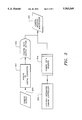
- FIG. 3 depicts the video digitizing and multiplexing system of the instant invention.
- FIG. 4 shows the asynchronous output capabilities of the instant invention.
- FIG. 2 therein depicted is a typical analog video camera system, including CCD Imager 201 regulated by Timing Generator and CCD Imager Driver 202.
- the output of CCD Imager 201 goes to the Sample and Hold and Automatic Gain Control Unit 203, which in turn drives the pixel processor 204 which produces the camera output signal along transmission line 205, the output produced is an analog varying voltage video signal such as depicted in FIG. 1.
- This signal can be transmitted for "real time" display, or can be recorded on an analog video recorder (VCR) (not shown).
- VCR analog video recorder
- the system of the instant invention receives the above-described analog video signal via line 205, converts this signal to a digital format via Analog to Digital Converter 301, and buffers the resulting digital signal via Camera Data Output Buffer 302.
- External Messaging Camera Controller 303 creates Camera Data Headers 304 that are multiplexed with the buffered digital signal by Camera Message Multiplexer 305.
- the Camera Data Headers comprise a Time Stamp, a Type indicator, and a Format indicator.
- the Multiplexer 305 combines the Headers with the digital video signal as follows: ⁇ [Headers]; [Y data]; [U data]; [V data] ⁇ .
- This combined output signal of Multiplexer 305 is then buffered by Camera Message Asynchronous Buffer 401 as shown in FIG. 4.
- the output of Buffer 401 can then be sent and received as a conventional asynchronous digital message that is compatible with standard computer systems as depicted in FIG. 4.
- This digital output can be one of many different types: e.g. (1) digitized RS-170; (2) CCIR-601; (3) CCD Imager Array (for example, Red, Cyan, Magenta, and Green); or (4) a specialized scaled digital video signal.
- the camera data header is used to specify initially which particular type is being used.
Landscapes
- Engineering & Computer Science (AREA)
- Multimedia (AREA)
- Signal Processing (AREA)
- Television Systems (AREA)
Abstract
Description
Claims (12)
Priority Applications (1)
| Application Number | Priority Date | Filing Date | Title |
|---|---|---|---|
| US08/293,141 US5583569A (en) | 1994-08-19 | 1994-08-19 | Video camera having asynchronous digital output including header data |
Applications Claiming Priority (1)
| Application Number | Priority Date | Filing Date | Title |
|---|---|---|---|
| US08/293,141 US5583569A (en) | 1994-08-19 | 1994-08-19 | Video camera having asynchronous digital output including header data |
Publications (1)
| Publication Number | Publication Date |
|---|---|
| US5583569A true US5583569A (en) | 1996-12-10 |
Family
ID=23127817
Family Applications (1)
| Application Number | Title | Priority Date | Filing Date |
|---|---|---|---|
| US08/293,141 Expired - Lifetime US5583569A (en) | 1994-08-19 | 1994-08-19 | Video camera having asynchronous digital output including header data |
Country Status (1)
| Country | Link |
|---|---|
| US (1) | US5583569A (en) |
Cited By (8)
| Publication number | Priority date | Publication date | Assignee | Title |
|---|---|---|---|---|
| EP0843960B1 (en) * | 1996-11-16 | 2001-11-21 | CLAAS KGaA | Device for controlling the overloading of goods of a working machine in a transport vehicle |
| US6373523B1 (en) * | 1995-10-10 | 2002-04-16 | Samsung Electronics Co., Ltd. | CCD camera with two CCDs having mutually different color filter arrays |
| US20030222990A1 (en) * | 2002-05-29 | 2003-12-04 | John Driska | Video camera for transmitting video, audio and control signals to a remote recording device |
| US20040085446A1 (en) * | 2002-10-30 | 2004-05-06 | Park Ho-Sang | Method for secured video signal transmission for video surveillance system |
| US20040085445A1 (en) * | 2002-10-30 | 2004-05-06 | Park Ho-Sang | Apparatus for secured video signal transmission for video surveillance system |
| US6813372B2 (en) | 2001-03-30 | 2004-11-02 | Logitech, Inc. | Motion and audio detection based webcamming and bandwidth control |
| US6985174B1 (en) | 2001-10-30 | 2006-01-10 | Logitech Europe S.A. | Dynamic radio frequency interference detection and correction |
| US20220149875A1 (en) * | 2019-03-21 | 2022-05-12 | Continental Automotive Gmbh | Method for estimating a signal-to-noise ratio |
Citations (5)
| Publication number | Priority date | Publication date | Assignee | Title |
|---|---|---|---|---|
| US3584145A (en) * | 1968-12-23 | 1971-06-08 | Bell Telephone Labor Inc | Time division multiplexing of video redundancy reduction data compressors |
| US5115426A (en) * | 1990-03-30 | 1992-05-19 | At&T Bell Laboratories | Broadband isdn packet switching arrangements |
| US5122875A (en) * | 1991-02-27 | 1992-06-16 | General Electric Company | An HDTV compression system |
| US5138440A (en) * | 1990-10-29 | 1992-08-11 | General Instrument Corporation | Method and apparatus for communicating a plurality of asynchronous signals over a digital communication path |
| US5287182A (en) * | 1992-07-02 | 1994-02-15 | At&T Bell Laboratories | Timing recovery for variable bit-rate video on asynchronous transfer mode (ATM) networks |
-
1994
- 1994-08-19 US US08/293,141 patent/US5583569A/en not_active Expired - Lifetime
Patent Citations (5)
| Publication number | Priority date | Publication date | Assignee | Title |
|---|---|---|---|---|
| US3584145A (en) * | 1968-12-23 | 1971-06-08 | Bell Telephone Labor Inc | Time division multiplexing of video redundancy reduction data compressors |
| US5115426A (en) * | 1990-03-30 | 1992-05-19 | At&T Bell Laboratories | Broadband isdn packet switching arrangements |
| US5138440A (en) * | 1990-10-29 | 1992-08-11 | General Instrument Corporation | Method and apparatus for communicating a plurality of asynchronous signals over a digital communication path |
| US5122875A (en) * | 1991-02-27 | 1992-06-16 | General Electric Company | An HDTV compression system |
| US5287182A (en) * | 1992-07-02 | 1994-02-15 | At&T Bell Laboratories | Timing recovery for variable bit-rate video on asynchronous transfer mode (ATM) networks |
Cited By (9)
| Publication number | Priority date | Publication date | Assignee | Title |
|---|---|---|---|---|
| US6373523B1 (en) * | 1995-10-10 | 2002-04-16 | Samsung Electronics Co., Ltd. | CCD camera with two CCDs having mutually different color filter arrays |
| EP0843960B1 (en) * | 1996-11-16 | 2001-11-21 | CLAAS KGaA | Device for controlling the overloading of goods of a working machine in a transport vehicle |
| US6813372B2 (en) | 2001-03-30 | 2004-11-02 | Logitech, Inc. | Motion and audio detection based webcamming and bandwidth control |
| US6985174B1 (en) | 2001-10-30 | 2006-01-10 | Logitech Europe S.A. | Dynamic radio frequency interference detection and correction |
| US20030222990A1 (en) * | 2002-05-29 | 2003-12-04 | John Driska | Video camera for transmitting video, audio and control signals to a remote recording device |
| US20040085446A1 (en) * | 2002-10-30 | 2004-05-06 | Park Ho-Sang | Method for secured video signal transmission for video surveillance system |
| US20040085445A1 (en) * | 2002-10-30 | 2004-05-06 | Park Ho-Sang | Apparatus for secured video signal transmission for video surveillance system |
| US20220149875A1 (en) * | 2019-03-21 | 2022-05-12 | Continental Automotive Gmbh | Method for estimating a signal-to-noise ratio |
| US11757480B2 (en) * | 2019-03-21 | 2023-09-12 | Continental Automotive Technologies GmbH | Method for estimating a signal-to-noise ratio |
Similar Documents
| Publication | Publication Date | Title |
|---|---|---|
| US4953025A (en) | Apparatus for defining an effective picture area of a high definition video signal when displayed on a screen with a different aspect ratio | |
| US5486853A (en) | Electrical cable interface for electronic camera | |
| US4364090A (en) | Method for a compatible increase in resolution in television systems | |
| EP0719036B1 (en) | Electronic still picture camera | |
| US5047858A (en) | Multiple image processing and display system | |
| US5229855A (en) | System and method for combining multiple composite video signals | |
| KR20000011752A (en) | Imaging apparatus | |
| US5550586A (en) | Video camera and image input device connected through signal line for transferring multiplex data, and image input system using them | |
| US6710802B2 (en) | Image recording apparatus and image reproducing apparatus | |
| EP1091572B1 (en) | Image pickup apparatus with function of adjusting incident light quantity | |
| US5583569A (en) | Video camera having asynchronous digital output including header data | |
| KR970006299B1 (en) | Multi-format digital image pick-up apparatus | |
| EP0716543A3 (en) | Multi-picture television receiver | |
| US5914755A (en) | Image transmission apparatus | |
| US5029326A (en) | Picture display system | |
| JPS63269690A (en) | Improvement in television | |
| CN112311959A (en) | Multi-channel analog camera data splicing processing system and method | |
| JP2603960B2 (en) | Signal conversion system | |
| JP2809322B2 (en) | Small screen display circuit for MUSE signal | |
| KR0124853Y1 (en) | Television broadcasting signal converter | |
| KR950004112B1 (en) | Digital image data filtering apparatus | |
| JP2896175B2 (en) | Angle of view converter | |
| KR0128684B1 (en) | Video signal process apparatus & method for displaying pip at once | |
| KR930002305B1 (en) | Simulation system of data | |
| KR20000011790A (en) | Imaging apparatus and recording/reproducing apparatus |
Legal Events
| Date | Code | Title | Description |
|---|---|---|---|
| AS | Assignment |
Owner name: INTEL CORPORATION, CALIFORNIA Free format text: ASSIGNMENT OF ASSIGNORS INTEREST;ASSIGNOR:KUZMA, ANDREW;REEL/FRAME:007126/0572 Effective date: 19940814 |
|
| STCF | Information on status: patent grant |
Free format text: PATENTED CASE |
|
| FEPP | Fee payment procedure |
Free format text: PAYOR NUMBER ASSIGNED (ORIGINAL EVENT CODE: ASPN); ENTITY STATUS OF PATENT OWNER: LARGE ENTITY |
|
| FPAY | Fee payment |
Year of fee payment: 4 |
|
| FEPP | Fee payment procedure |
Free format text: PAYER NUMBER DE-ASSIGNED (ORIGINAL EVENT CODE: RMPN); ENTITY STATUS OF PATENT OWNER: LARGE ENTITY Free format text: PAYOR NUMBER ASSIGNED (ORIGINAL EVENT CODE: ASPN); ENTITY STATUS OF PATENT OWNER: LARGE ENTITY |
|
| FPAY | Fee payment |
Year of fee payment: 8 |
|
| FPAY | Fee payment |
Year of fee payment: 12 |
|
| REMI | Maintenance fee reminder mailed |