US4380696A - Method and apparatus for manipulator welding apparatus with vision correction for workpiece sensing - Google Patents
Method and apparatus for manipulator welding apparatus with vision correction for workpiece sensing Download PDFInfo
- Publication number
- US4380696A US4380696A US06/206,279 US20627980A US4380696A US 4380696 A US4380696 A US 4380696A US 20627980 A US20627980 A US 20627980A US 4380696 A US4380696 A US 4380696A
- Authority
- US
- United States
- Prior art keywords
- workpiece
- manipulator
- weld
- control apparatus
- path
- Prior art date
- Legal status (The legal status is an assumption and is not a legal conclusion. Google has not performed a legal analysis and makes no representation as to the accuracy of the status listed.)
- Expired - Lifetime
Links
Images


Classifications
-
- B—PERFORMING OPERATIONS; TRANSPORTING
- B25—HAND TOOLS; PORTABLE POWER-DRIVEN TOOLS; MANIPULATORS
- B25J—MANIPULATORS; CHAMBERS PROVIDED WITH MANIPULATION DEVICES
- B25J19/00—Accessories fitted to manipulators, e.g. for monitoring, for viewing; Safety devices combined with or specially adapted for use in connection with manipulators
- B25J19/02—Sensing devices
- B25J19/021—Optical sensing devices
- B25J19/023—Optical sensing devices including video camera means
-
- G—PHYSICS
- G05—CONTROLLING; REGULATING
- G05B—CONTROL OR REGULATING SYSTEMS IN GENERAL; FUNCTIONAL ELEMENTS OF SUCH SYSTEMS; MONITORING OR TESTING ARRANGEMENTS FOR SUCH SYSTEMS OR ELEMENTS
- G05B19/00—Programme-control systems
- G05B19/02—Programme-control systems electric
- G05B19/42—Recording and playback systems, i.e. in which the programme is recorded from a cycle of operations, e.g. the cycle of operations being manually controlled, after which this record is played back on the same machine
-
- G—PHYSICS
- G05—CONTROLLING; REGULATING
- G05B—CONTROL OR REGULATING SYSTEMS IN GENERAL; FUNCTIONAL ELEMENTS OF SUCH SYSTEMS; MONITORING OR TESTING ARRANGEMENTS FOR SUCH SYSTEMS OR ELEMENTS
- G05B2219/00—Program-control systems
- G05B2219/30—Nc systems
- G05B2219/36—Nc in input of data, input key till input tape
- G05B2219/36043—Correction or modification of program
-
- G—PHYSICS
- G05—CONTROLLING; REGULATING
- G05B—CONTROL OR REGULATING SYSTEMS IN GENERAL; FUNCTIONAL ELEMENTS OF SUCH SYSTEMS; MONITORING OR TESTING ARRANGEMENTS FOR SUCH SYSTEMS OR ELEMENTS
- G05B2219/00—Program-control systems
- G05B2219/30—Nc systems
- G05B2219/36—Nc in input of data, input key till input tape
- G05B2219/36417—Programmed coarse position, fine position by alignment, follow line, path adaptive
-
- G—PHYSICS
- G05—CONTROLLING; REGULATING
- G05B—CONTROL OR REGULATING SYSTEMS IN GENERAL; FUNCTIONAL ELEMENTS OF SUCH SYSTEMS; MONITORING OR TESTING ARRANGEMENTS FOR SUCH SYSTEMS OR ELEMENTS
- G05B2219/00—Program-control systems
- G05B2219/30—Nc systems
- G05B2219/36—Nc in input of data, input key till input tape
- G05B2219/36503—Adapt program to real coordinates, software orientation
-
- G—PHYSICS
- G05—CONTROLLING; REGULATING
- G05B—CONTROL OR REGULATING SYSTEMS IN GENERAL; FUNCTIONAL ELEMENTS OF SUCH SYSTEMS; MONITORING OR TESTING ARRANGEMENTS FOR SUCH SYSTEMS OR ELEMENTS
- G05B2219/00—Program-control systems
- G05B2219/30—Nc systems
- G05B2219/37—Measurements
- G05B2219/37572—Camera, tv, vision
-
- G—PHYSICS
- G05—CONTROLLING; REGULATING
- G05B—CONTROL OR REGULATING SYSTEMS IN GENERAL; FUNCTIONAL ELEMENTS OF SUCH SYSTEMS; MONITORING OR TESTING ARRANGEMENTS FOR SUCH SYSTEMS OR ELEMENTS
- G05B2219/00—Program-control systems
- G05B2219/30—Nc systems
- G05B2219/45—Nc applications
- G05B2219/45135—Welding
Definitions
- the present invention relates generally to manipulator welding apparatus and more particularly to control apparatus utilizing a vision correction system for workpiece sensing to operate manipulator welding apparatus to visually detect the deviation between a taught welding path and the actual seam to be welded during a first step and to perform welding along the actual seam of a particular workpiece during a second step.
- control apparatus for manipulator welding apparatus for accurately performing a taught welding path on successive workpieces and accounting for deviations in workpiece position from the workpiece on which the weld path was initially taught.
- the control apparatus includes a vision correction system for workpiece sensing.
- the manipulator is taught the desired welding path on a workpiece by the appropriate recording of data representing the welding path as an operator controls movement of the manipulator.
- data representing a reference image or template is also recorded in the teach mode.
- the reference image or template data is provided by a vision system including a camera carried by the manipulator arm.
- the manipulator is controlled to move in accordance with the recorded taught data in a first repeat pass wherein images of the welding seam region are detected at successive points along the taught path.
- the vision system utilizing an image processor visually detects the deviation between the taught welding path and the actual welding path of the workpiece.
- the image processor by means of the visual detection in the first repeat pass provides deviation data representing the deviation between a taught standard path and the actual welding path of the workpiece.
- the control apparatus in response to the deviation data provided by the image processor in the first repeat pass corrects the recorded taught data to provide corrected welding path data for the particular workpiece position encountered by the manipulator.
- a second repeat pass of the repeat work cycle mode welding of the actual workpiece seam is performed in accordance with the corrected welding path data obtained in the first repeat pass.
- the first and second repeat passes of the repeat mode are performed for each workpiece.
- the manipulator is taught the desired welding path with a weld tip in the appropriate welding position. Further a camera of the vision system carried by the manipulator arm during the teach mode is appropriately positioned to provide the reference image or template.
- the vision system on the manipulator arm is appropriately positioned to move over the taught path.
- the weld gun is positioned to perform the welding.
- the vision system and the weld gun of the manipulator arm are provided by portions of the vision system being mounted on the manipulator arm along with the weld gun.
- the vision system and the weld gun are presented to the workpiece in an aligned fasion.
- the vision system and the weld gun are mounted on the hand with appropriate rotation of the manipulator hand at the end of the robot arm selectively presenting either the vision system or the weld gun.
- two separate manipulator hands are provided; one hand carrying the appropriate portions of the vision system such as a camera head and an optical pattern projection unit that is utilized for detection and a second hand including the weld gun to perform the welding and to teach the desired welding path.
- FIG. 1 is a perspective view of a programmable manipulator adjacent a workpiece welding station and a functional representation of the control apparatus of the present invention
- FIG. 2 is a perspective view of another form of a programmable manipulator adjacent a workpiece welding station and a block diagram representation of the control apparatus of the present invention of FIG. 1;
- FIGS. 3 and 4 are perspective views representative of respective workpieces to be welded in accordance with the control apparatus of FIGS. 1 and 2 and illustrating projected light patterns of the vision system of the present invention
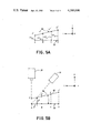
- FIG. 5A is a graphical plan view representation
- FIG. 5B is a front elevational view of a taught weld path on a workpiece and a corrected weld path in accordance with the principles of the present invention
- FIG. 6 is a flow diagram illustrating the method of the present invention and the general operation of the control apparatus of the present invention of FIGS. 1 through 5 to accomplish welding of a workpiece;
- FIG. 7 is an enlarged, elevational view of the manipulator arm of the present invention of FIGS. 1 and 2 and illustrating one hand arrangement to practice the present invention including a visual detection system and a weld gun.
- FIG. 8 is an elevational view of a weld gun hand
- FIG. 9 is an elevational view of a vision system hand that provides minimal interference to the work piece environment.
- FIG. 10 is an elevational view of an alternate vision system hand.
- manipulator apparatus or robot 10 is illustrated adjacent a work station 12 to accomplish the welding of a workpiece generally referred to at 14 in accordance with the principles of the present invention.
- the workpiece 14, for example, as illustrated in FIG. 1 includes two metal plates 16, 18 which are to be welded along the abutting seam formed therebetween.
- the manipulator 10 includes a manipulator arm 20 that is provided with a hand or tool receiving portion 22.
- a manipulator hand arrangement 24 is positioned on the receiving portion 22.
- the hand 24 carries a weld gun 26 and a camera or other suitable imaging device 28.
- An optical pattern projection unit 30 is arranged either on the hand 24 or at a suitable fixed reference position independent of the hand.
- the weld gun 26 is connected to welding equipment referred to generally at 32 that provides a welding wire feed system at 34 to the weld gun 26 along with other suitable electrical interconnections and a welding gas supply in accordance with conventional welding practices.
- the camera 28 is controlled by and provides imaging signals to a camera controller arrangement 36 over signal and control lines 38.
- the camera controller arrangement 36 is connected to provide signals to an image processing unit 40.
- the camera 28, the optical projection unit 30, the camera controller 36 and the image processing unit 40 comprise a vision system substantially as shown and described in the aforementioned copending Masaki application Ser. Nos. 077,320, 066,323 and 106,039.
- the image processing unit 40 is interconnected over data lines 42 to a data transformation system and system controller 44 of the present invention.
- the data transformation system and system controller 44 controls operation of the manipulator welding system and controls operation of the manipulator 10 by means of a servo control system referred to generally at 46.
- the data transformation system and system controller 44 supplies the appropriate control signals to the servo control system 46 as command signals to position the manipulator arm 20 in one or more controllable axes.
- an operator controls the manipulator arm 20 in the controllable axes to move the tip of the weld gun 26 over a desired welding path with respect to the taught workpiece 14.
- appropriate welding path data is recorded in the system controller 44 representing taught points along the desired welding path.
- the projection unit 30 is operatively positioned to project a light pattern on the workpiece 14.
- the camera 28 along with the camera controller 36 and the image processing unit 40 provide a reference or template image for storage along with the taught path data.
- the projection unit 30 projects an optical slit pattern on the workpiece 14 and the vision system components including the camera 28, the camera controller 36 and the image processing unit 40 detect the optical pattern as transformed by the shape of the surface of the workpiece 14.
- the reference or template image is taken at one or more suitable locations along the taught welding path as dependent upon the geometry of the welding path.
- welding data is also recorded including desired weld speed and other appropriate parameters of the welding operation.
- reference template image is taken with a reference work piece and the taught welding path is recorded during the first repeat pass of the first repeat workpiece as well be explained in detail hereinafter. The taught path for the first repeat work piece is then utilized for successive work pieces.
- the manipulator 10 is controlled to perform a repeat mode including a first repeat pass during which the manipulator arm 20 is controlled to move over the taught welding path at a speed much higher than weld speed in accordance with the stored taught data with the camera 28 operatively positioned over the taught welding path.
- the image processing unit 40 over data lines 42 provides deviation data from the detected workpiece images at suitable points along the welding path representing the deviation of the actual welding seam presented by the workpiece 14 from the taught welding path template image.
- the system controller 44 in accordance with the stored taught data and the deviation data from the image processing unit 40 calculates and stores corrected welding path data for the present workpiece 14 accounting for any changes in location of the workpiece 14 from that of the taught reference workpiece in the teach phase.
- the weld gun 26 is operatively positioned over the workpiece 14 and the corrected path data calculated and stored in the first repeat pass is utilized to control the manipulator arm 20 to weld the desired welding path on the workpiece 14 in cooperation with the operation of the welding equipment 32.
- the desired welding path is taught and recorded on a reference workpiece 14 during a single teach mode and as successive workpieces 14 are presented to the manipulator 10, the repeat mode with the two repeat passes is performed for each of the workpieces.
- FIG. 2 another type of manipulator 10 is illustrated for operation on a workpiece 14.
- the system controller 44 of the present invention is shown with appropriate data and control interconnections with the servo control system of the robot controller 46, the image processor 40, the camera 36, the welding equipment 32 including a welding controller 50 and a welding power source 52, and a laser driver stage 54 for operation of the projection unit 30 as a laser head.
- the manipulator 10 suitable for use in practice of the present invention includes various types of programmable manipulators or robots.
- a manipulator 10 as shown in FIG. 1 is commercially available from Unimation, Inc. as a UNIMATE (Trademark of Unimation, Inc.) type 2000 manipulator and the manipulator 10 of FIG. 2 is commerically available from Unimation, Inc. as a PUMA (Trademark of Unimation, Inc.) type 500 arm.
- the PUMA type 500 manipulator arm shown in FIG. 2 includes a microprocessor based control system operating in accordance with VAL (Trademark of Unimation, Inc.) programming and control system for computer controlled robots and manipulators.
- VAL Trademark of Unimation, Inc.
- the system controller 44 of FIGS. 1 and 2 in one arrangement of the present invention is operable as a VAL robot programming and control system as additionally enhanced by the data transformation system of the system controller 44 as will be explained in more detail hereinafter.
- the system controller 44 for the manipulator 10 of FIG. 1 in other arrangements utilizes the respective control system as further described in U.S. Pat. Nos. 3,661,051, 4,086,522, 4,163,183 and copending application Ser. No. 154,439 filed by W. Perzley et al. on May 29, 1980 to which reference may be made for a more detailed discussion of suitable types of control systems for use in connection with the present invention.
- the operation of the vision system of FIGS. 1 and 2 including the camera 28, the projection unit 30, the camera controller 36 and the image processing unit 40 for providing a deviation output signal by comparison of a reference template image and an actual image is disclosed in the aforementioned copending Masaki application Ser. Nos. 077,320, 066,323 and 106,039 to which reference may be made for a more detailed discussion of the structure and operation of the vision system of FIGS. 1 and 2.
- the projection unit 30 projects an optical slit pattern onto the generally perpendicularly arranged workpiece portions 60, 62.
- the workpiece portions 60, 62 transform the optical pattern projected by the unit 30 in accordance with the surface shape and position of the workpiece portions; for example, as depicted by line pattern 64 on workpiece portion 62 and line pattern 66 on workpiece portion 60.
- This type of optical pattern projection is useful for path correction systems including arc welding, sealing, brazing and the like.
- the camera 28 detects the transformed light pattern image including image pattern portions 64 and 66; the intersection of the lines 64, 66 defining the points along the intersection seam 68 of the workpiece portions 60, 62 to be welded for various positions of the camera 28 and the projection unit 30.
- the camera 28 detects the image portions 64, 66 of the actual welding seam 68 in accordance with the position of the workpiece portions 60, 62.
- FIG. 4 a second example of a welding application is illustrated therein for welding the lap seam between the generally planar and overlapping workpiece portions 70, 72.
- the optical projected slit pattern from the projection unit 30 forms an image as transformed by the shape of the workpiece portions 70, 72 including a first line image 74 on the workpiece portion 70 and a second line portion 76 on the workpiece portion 72.
- FIGS. 3 and 4 are typical of the reference template image recorded by the image processor 40 in the teach mode for a reference workpiece and are also typical of the actual images formed by the successive workpieces in the repeat modes as detected by the camera 28 during the first pass of the repeat mode in accordance with operation on each successive workpiece.
- an illustrative example of a taught path 68 includes the taught points A, B, C and D for example defining the straight line welding seam 68 to be welded on the workpiece portion 60, 62 of FIG. 3.
- data representing the taught points A, B, C and D are recorded and stored in the system controller 44 in accordance with movement of the weld gun 26 over the taught path 68.
- the reference image or template 64, 66 detected by the camera 28 is also stored in the image processor 40.
- the reference image 64, 66 is recorded at only one point along the teach path 68 since the geometry of the weld seam 68 results in a constant image being obtained at the various points along the desired welding path.
- the manipulator 10 In the first repeat pass of the repeat mode for a workpiece 14 presented to the manipulator 10 and with the camera 28 in the operative position, the manipulator 10 is controlled to move in accordance with the taught path data at a relatively high rate of speed with the camera 28 obtaining slit pattern images resulting from the projected pattern from unit 30 on the workpiece 14 at the various taught points A, B, C and D in one specific arrangement.
- the image processing unit 40 calculates and provides respective deviation data D a , D b , D c and D d representing two-dimensional deviation data in an X-Z reference plane and including ⁇ X and ⁇ Z components.
- the system controller 44 during the first repeat pass and in accordance with the deviation data D a , D b , D c and D d and the taught data representing the points A, B, C and D, calculates a corrected welding path represented by the corrected data points, A', B', C', and D' defining the actual welding seam presented by the newly positioned workpiece 14 representing positional changes from the taught reference workpiece position in the X and Z reference axes.
- the system controller 44 utilizes absolute position data provided by digital encoders of the manipulator apparatus 10 and the deviation data D a , D b , D c and D d to provide the corrected data points A', B', C', and D'.
- the plan view of the taught path 68 and the corrected path 80 represents for example the plan view of the workpiece weld path of FIG. 3.
- the ⁇ X components of the deviation D in depicted.
- the ⁇ Y deviation component illustrates the deviation in the Y-Z reference plane an detected by the image processing unit 40.
- FIG. 6 the flow diagram of FIG. 6 represents the operation of the present invention including the additional functions performed by the system controller 44 in addition to available manipulator control arrangements such as the PUMA type 500 arm with VAL control programming discussed hereinbefore.
- the start of the flow program of the system controller 44 proceeds through the teach mode 84 wherein the function block 86 represents the teaching of the reference template image in accordance with the data from a vision system with the camera 28 in the operative position and the projection unit 30 projecting the slit pattern resulting in image 64, 66 of FIG. 3 onto the taught reference workpiece.
- the program flow proceeds to a function block 88 representing the teaching of the desired welding path on the reference workpiece 14 for example by the movement of the manipulator along the welding path 68 of FIG. 3 and the storing of data representing the taught points A, B, C and D of FIG. 5.
- the program flow proceeds to a function block 90 wherein other appropriate teaching information is recorded such as the desired welding speed and other parameters of the welding operation.
- the teach step 90 also includes appropriate weld gun and camera position definition data as may be necessary due to offsets of the weld gun point and optical center point of the manipulator hand from a reference point.
- the teach step 90 includes the inputting of data representing and defining either the offsets of the hand 24 in the camera and weld gun positions or two separately attached hands in a specific arrangement wherein a camera hand and a separate weld gun hand are provided.
- the program flow of the system controller 44 then proceeds to the repeat modes 91 and specifically at flow point 92 into the first repeat mode or pass 94.
- a function block 96 represents operation of the servo controller 46 moving the manipulator 10 at a high rate of speed to the first taught point.
- an actual image at taught point A is obtained from the vision system.
- the flow of the program proceeds to a function block 100 wherein the image processing unit 40 calculates the deviation D a and provides this deviation to the system controller 44.
- the program flow proceeds to a function block 102 wherein the system controller 44 calculates the position of the actaul seam as data point A' from the deviation data D a and the taught data point A.
- the program flow proceeds to the decision block 104 to determine whether or not the first repeat pass has been completed encompassing the calculation of corrected path data for each of the taught data points, for example A, B, C and D.
- the result in decision block 104 is NO and the program flow proceeds via signal line 106 back to program flow point 92 to the function block 96.
- the taught data is incremented by one data point and the first repeat pass flow 94 continues to calculate the corrected data B', C' and D' corresponding to the respective taught points B, C and D when the manipulator arm 20 is moved to each of the taught points B, C and D.
- the flow diagram of FIG. 6 is merely illustrative of one specific embodiment of the present invention.
- the corrected data A', B', C' and D' are calculated after the arm has been moved to all the taught points A, B, C and D and the respective deviation data D a , D b , D c and D d are obtained.
- the result in decision block 104 is yes and the program flow proceeds through flow point 108 to the second repeat mode or second repeat pass 110 of the repeat mode 91.
- a function block 112 proceeds to condition the manipulator 10 for welding the actual seam of the workpiece in accordance with the actual welding path 80 defined by the corrected data points A', B', C' and D' stored in the system controller 44 as a result of the first repeat mode 94.
- the function block 112 proceeds to condition the manipulator 10 to weld the actual seam with appropriate control of the welding equipment 32 and the desired recorded speed of movement along the actual path 80 in accordance with the data entered in the teach mode.
- the manipulator arm 20 is controlled to move the weld gun 26 over the path defined by the points A', B', C' and D'.
- the program flow proceeds to the decision block 114 to determine whether the next workpiece to be welded is in position. If the determination is YES signifying that another workpiece is to be welded and is in position for welding, the program flow proceeds from the decision block 114 over the signal path 116 to the flow point 92 at the beginning of the first repeat mode 94.
- the first and second repeat modes 94 and 110 respectively are accomplished with the next workpiece being sensed in the first repeat mode, the actual welding path being calculated, and the welding path being welded in the second repeat mode 110.
- next workpiece indication in the block 114 is provided in specific arrangements by either external operator input, or by control inputs of the system controller 44 via automated workpiece transfer apparatus, or by a sensing function performed by the manipulator 10.
- the weld gun 26 is positioned and carried on the manipulator hand 24 at a position approximately 180 degrees apart from the optical pattern projection unit 30 and the camera 28.
- the weld gun 26 defines a weld point 122 and the camera 28 and optical pattern projection unit 30 define an optical center reference point 124 at the intersection of their respective optical axes.
- the weld point 122 and the optical center point 124 are approximately 180 degrees apart on the hand 24.
- the manipulator arm 20 includes a controllable axis defining an articulated joint at 126 providing a yaw or wrist swivel movement to rotate the hand 24 to provide the presentation of either the weld gun 26 at weld point 122 or the vision system at optical center point 124 over the welding seam of the workpiece.
- the manipulator arm 20 selectively presents either the optical center point 124 or the weld point 122 to the workpiece.
- the weld point 122 is presented during portions of the teach mode and during the second repeat pass.
- the optical center point is positioned over the workpiece during a portion of the teach mode and also during the first repeat pass.
- the system controller 44 includes appropriate hand definition data including the transformation of coordinates defining the various respective offset of the optical center point and the weld point to appropriately position either the optical center point or the weld point at the stored data points representing either taught data or corrected path data. Further, during the teach mode, the offset data of the weld point and the optical center point are utilized to allow accurate positioning of the camera 28 or the weld gun 26 and the appropriate recording of position data defining manipulator arm position in each of the controlled axes.
- the weld gun 26, and the camera 28 are mounted on the hand 24 such that both the camera axis and the weld point 122 are simultaneously aligned with and presented to the workpiece. Further, the projection unit 30 is also mounted on the hand 24 with the optical center point 124 being aligned with the work piece simultaneously with the weld point 122.
- the manipulator automatically and selectively attaches one of the hands as required for the particular programmed operation as explained in connection with FIG. 6.
- the exchange between the hands is also automatically provided by the manipulator 10 in accordance with the programmed operation of the system controller 44.
- the hand not currently being used by the manipulator 10 is placed in a hand holder (not shown).
- the manipulator 10 in accordance with programmed control automatically exchanges the hands from the respective hand holder stations as required by placing one hand in one hand holder station and picking up the second hand in a second hand holder station.
- the various transformation offsets between each of the hands and the manipulator arm hand reference point at the hand attachment are also stored by the system controller to enable proper positioning of each of the hands and the accurate recording of arm position data. It should be noted that the various embodiments of the hands 24, 140, 142 and 144 provide minimal intrusion problems to the work piece environment to avoid obstructions in the work piece environment.
- the deviation data obtained from the image processing unit 40 in the first repeat mode is presented to the system controller 44 in coordinates relative to the orientation of the coordinate axes of the camera 28.
- the deviation data at a particular point i referred to hereinbefore as D i is represented by X and Z components ⁇ X i and ⁇ Z i , respectively denoting horizontal and vertical deviation as referenced in FIG. 5.
- the deviation in a matrix format is defined as follows: ##EQU1## Appropriate reading of the deviation components is provided by the system controller 44.
- a transformation matrix [C w ] from camera coordinates to a world generalized coordinate reference of the manipulator is obtained as follows:
- [R w ] represents the transformation matrix from wrist reference coordinates of the manipulator to generalized world coordinates
- [C R ] represents the transformation matrix from camera reference coordinates to wrist coordinates
- a target or destination point [P w ] in the repeat mode for welding includes the corrected coordinates for the weld gun in generalized world coordinates and is defined as follows:
- [R' w ] the coordinate matrix that describes the corrected position and orientation for the manipulator wrist in generalized world coordinates.
- the matrix [R' w ] is obtained as follows:
- the matrix [R' w ] is used to control operation and positioning of the manipulator 10 in the second repeat mode in accordance with the following relationship:
- the taught point data is utilized directly to obtain the corrected weld path coordinates in accordance with the deviation data obtained in the first repeat pass.
- the deviation obtained at a particular taught point i is represented as [DEV] i and represents the deviation defining the corrected weld point relative to the camera coordinates in the first repeat pass.
- the corrected weld point [REPEAT] i is obtained as follows:
- VAL program and control system includes the definition of a MOVCAM A, A' function or instruction that defines the movement of the manipulator arm to location A, reading the camera deviation [DEV] at location A via the image processor, and defining the location of a corrected point A' therefrom.
- the two tools CAMERA and WELD GUN are defined corresponding to the respective TOOL CAMERA and TOOL WELD steps with the VAL program and control system incorporating the TOOL [ ⁇ transformation>] program instruction setting the value of tool transformation to the value defined in the brackets ⁇ transformation>.
- the effect of the TOOL command results in the monitoring by the VAL system to account for the transformation offset matrix of the defined tool; i.e., an internal matrix representing the tool offset coordinates is automatically taken into consideration each time data is to be recorded or each time the manipulator is moved to a defined point.
- the SPEED WELD of step 2 in PROGRAM TEACH enters the desired welding speed, for example 5 units/second.
- the SPEED REPEAT of step 2 of REPEAT PASS ONE enters the desired repeat speed, for example, 200 units/second.
- the PROGRAM TEACH sequence is not performed and only the PROGRAM REPEAT sequence of steps 1-14 is necessary along with the teaching of a reference image template.
- the MOVCAM steps include movement by the operator and the teach controls to the designated points A, B, C and D in addition to the generation of the deviation via the image processor and the defining of the corrected data points A', B', C' and D'.
- the program steps 1-14 of the PROGRAM REPEAT sequence are performed and the operation is as described hereinbefore with the MOVCAM steps operating in accordance with the data A, B, C, and D entered for the first repeat work piece.
Landscapes
- Engineering & Computer Science (AREA)
- Physics & Mathematics (AREA)
- General Physics & Mathematics (AREA)
- Automation & Control Theory (AREA)
- Multimedia (AREA)
- Robotics (AREA)
- Mechanical Engineering (AREA)
- Numerical Control (AREA)
- Manipulator (AREA)
Abstract
Control apparatus for manipulator welding apparatus is provided that includes a vision correction system for workpiece sensing. During an initial teach mode, the manipulator is taught the desired welding path on a workpiece by the appropriate recording of data representing the welding path as an operator controls movement of the manipulator. In addition to the data representing the taught welding path, data representing a reference image or template is also recorded in the teach mode. The reference image or template data is provided by a vision system including a camera carried by the manipulator arm. As successive workpieces are presented to the manipulator for performing the desired welding path, in a repeat work cycle mode the manipulator is controlled to move in accordance with the recorded taught data in a first repeat pass wherein images of the welding seam region are detected at successive points. The vision system utilizing an image processor detects the deviation between the taught welding path and the actual welding path of the workpiece. The control apparatus in response to the deviation data provided by the image processor in the first repeat pass corrects the recorded taught data to provide corrected welding path data for the particular workpiece orientation and geometry encountered by the manipulator. During a second repeat pass of the repeat work cycle mode, welding of the actual workpiece seam is performed in accordance with the corrected welding path data obtained in the first repeat pass.
Description
1. Field of the Invention
The present invention relates generally to manipulator welding apparatus and more particularly to control apparatus utilizing a vision correction system for workpiece sensing to operate manipulator welding apparatus to visually detect the deviation between a taught welding path and the actual seam to be welded during a first step and to perform welding along the actual seam of a particular workpiece during a second step.
2. Description of the Prior Art
Various welding apparatus and vision detection systems have been proposed. For example, copending applications Ser. No. 106,039 filed by I. Masaki on Dec. 21, 1979 provides a method and apparatus for detecting any positional deviation of a workpiece from a reference position by means of a visual detection system and an image processor. Further, copending application Ser. No. 066,323 filed by I. Masaki on Aug. 14, 1979 and copending application Ser. No. 077,320 filed by I. Masaki on Sept. 20, 1979 disclose arrangements for interrupting the welding operation and performing the detection of images of the workpiece during the time that the welding is interrupted or the welding current is decreased. Further welding apparatus with control arrangements are disclosed in U.S. Pat. No. 4,115,684 which issued to T. H. Lindbom on Sept. 19, 1978, U.S. Pat. No. 4,086,522 which issued to J. F. Engelberger et al. on Apr. 25, 1978, U.S. Pat. No. 4,030,617 which issued to H. Richter on June 21, 1977, U.S. Pat. No. 4,105,937 which issued to G. Tuda et al. on Aug. 8, 1978 and copending application Ser. No. 154,439 filed by W. Perzley et al. on May 29, 1980.
While the above described arrangements are generally suitable for their intended use, it is difficult to obtain image data of the sensed workpiece during welding. Even in the arrangements where provisions are made to decrease welding current or interrupt welding to obtain images of the workpiece, optical noise in the vision system is still a problem. Further, the vision system is subjected to the welding environment with possible detrimental effects on the vision system. Additionally, if the sensing of the workpiece welding seam is performed during the actual welding of the seam, the vision system carried on the manipulator arm must be positioned near the weld tip. In addition to the vision system being exposed to the welding environment and optical noise resulting therefrom, the weld gun and vision system arrangement may cause clearance problems with obstructions on or around the workpiece and may present various obstacles to the manipulator hand being controlled to move over the welding path. Further, if image data of the workpiece is obtained during the welding operation to provide path correction data, the path computation data must be calculated during the welding process and as the manipulator arm moves over the welding path.
Accordingly it is a principal object of the present invention to provide a control method and apparatus for manipulator welding apparatus having a vision correction system for workpiece sensing that overcomes one or more of the above described disadvantages of the prior art arrangements.
It is another object of the present invention to provide a control method and apparatus for manipulator welding apparatus having a vision correction system for workpiece sensing wherein a desired welding path is taught on a workpiece during a teach mode, and for each successive workpiece presented to the manipulator a vision correction system detects the deviation between the taught path and the actual workpiece path to be welded during a first repeat pass over the workpiece, corrected path data is calculated from the deviation data that represents the desired welding path for the particular workpiece position and the corrected path data is utilized during a second repeat pass to perform the welding along the desired path.
It is another object of the present invention to provide method and apparatus for manipulator welding apparatus wherein path correction data is obtained for a particular workpiece representing the deviation between a taught path and an actual workpiece path accounting for changes in workpiece position before the manipulator performs the welding of the desired welding path.
It is a further object of the present invention to provide a manipulator hand for a manipulator arm including a vision system and a weld gun wherein the manipulator hand may be rotated to selectively position either the vision system or the weld gun at a work location.
It is another object of the present invention to provide a method and apparatus for manipulator welding apparatus with a vision correction system for performing corrections to a taught work path wherein the detection of the actual work path and the correction of taught work path data is accomplished independently of the welding of the workpiece.
It is yet another object of the present invention to provide a method and apparatus for manipulator welding apparatus utilizing a vision correction system that corrects a taught path for changes in workpiece position from a taught workpiece location during a first repeat pass over the workpiece at a relatively high speed compared to that of the welding speed and prior to the time of a second repeat pass during which the welding is accomplished in accordance with the corrected path data.
Briefly, these and other objects of the present invention are achieved by providing control apparatus for manipulator welding apparatus for accurately performing a taught welding path on successive workpieces and accounting for deviations in workpiece position from the workpiece on which the weld path was initially taught. The control apparatus includes a vision correction system for workpiece sensing. During an initial teach mode, the manipulator is taught the desired welding path on a workpiece by the appropriate recording of data representing the welding path as an operator controls movement of the manipulator. In addition to the data representing the taught welding path, data representing a reference image or template is also recorded in the teach mode. The reference image or template data is provided by a vision system including a camera carried by the manipulator arm. As successive workpieces are presented to the manipulator for performing the desired welding path, in a repeat work cycle mode the manipulator is controlled to move in accordance with the recorded taught data in a first repeat pass wherein images of the welding seam region are detected at successive points along the taught path. The vision system utilizing an image processor visually detects the deviation between the taught welding path and the actual welding path of the workpiece. The image processor by means of the visual detection in the first repeat pass provides deviation data representing the deviation between a taught standard path and the actual welding path of the workpiece. The control apparatus in response to the deviation data provided by the image processor in the first repeat pass corrects the recorded taught data to provide corrected welding path data for the particular workpiece position encountered by the manipulator. During a second repeat pass of the repeat work cycle mode, welding of the actual workpiece seam is performed in accordance with the corrected welding path data obtained in the first repeat pass. When successive workpieces are provided to the manipulator, the first and second repeat passes of the repeat mode are performed for each workpiece. During the teach mode, the manipulator is taught the desired welding path with a weld tip in the appropriate welding position. Further a camera of the vision system carried by the manipulator arm during the teach mode is appropriately positioned to provide the reference image or template. During the first repeat pass of the repeat mode, the vision system on the manipulator arm is appropriately positioned to move over the taught path. In the second repeat pass of the repeat mode, the weld gun is positioned to perform the welding. Any positional offsets between the optical center of the vision system on the manipulator arm and the weld point of the weld gun are accounted for by the control apparatus to provide appropriate data. In one arrangement, the vision system and the weld gun of the manipulator arm are provided by portions of the vision system being mounted on the manipulator arm along with the weld gun. In a first specific embodiment of this arrangement, the vision system and the weld gun are presented to the workpiece in an aligned fasion. In a second specific embodiment of this arrangement, the vision system and the weld gun are mounted on the hand with appropriate rotation of the manipulator hand at the end of the robot arm selectively presenting either the vision system or the weld gun. In another arrangement, two separate manipulator hands are provided; one hand carrying the appropriate portions of the vision system such as a camera head and an optical pattern projection unit that is utilized for detection and a second hand including the weld gun to perform the welding and to teach the desired welding path.
The invention both as to its organization and method of operation together with further objects and advantages thereof will best be understood by reference to the following specification taken in conjunction with the accompanying drawings.
FIG. 1 is a perspective view of a programmable manipulator adjacent a workpiece welding station and a functional representation of the control apparatus of the present invention;
FIG. 2 is a perspective view of another form of a programmable manipulator adjacent a workpiece welding station and a block diagram representation of the control apparatus of the present invention of FIG. 1;
FIGS. 3 and 4 are perspective views representative of respective workpieces to be welded in accordance with the control apparatus of FIGS. 1 and 2 and illustrating projected light patterns of the vision system of the present invention;
FIG. 5A is a graphical plan view representation and
FIG. 5B is a front elevational view of a taught weld path on a workpiece and a corrected weld path in accordance with the principles of the present invention;
FIG. 6 is a flow diagram illustrating the method of the present invention and the general operation of the control apparatus of the present invention of FIGS. 1 through 5 to accomplish welding of a workpiece;
FIG. 7 is an enlarged, elevational view of the manipulator arm of the present invention of FIGS. 1 and 2 and illustrating one hand arrangement to practice the present invention including a visual detection system and a weld gun.
FIG. 8 is an elevational view of a weld gun hand;
FIG. 9 is an elevational view of a vision system hand that provides minimal interference to the work piece environment; and
FIG. 10 is an elevational view of an alternate vision system hand.
Referring now to FIG. 1, manipulator apparatus or robot 10 is illustrated adjacent a work station 12 to accomplish the welding of a workpiece generally referred to at 14 in accordance with the principles of the present invention. The workpiece 14, for example, as illustrated in FIG. 1 includes two metal plates 16, 18 which are to be welded along the abutting seam formed therebetween. The manipulator 10 includes a manipulator arm 20 that is provided with a hand or tool receiving portion 22. A manipulator hand arrangement 24 is positioned on the receiving portion 22. In one arrangement of the present invention, the hand 24 carries a weld gun 26 and a camera or other suitable imaging device 28. An optical pattern projection unit 30 is arranged either on the hand 24 or at a suitable fixed reference position independent of the hand. The weld gun 26 is connected to welding equipment referred to generally at 32 that provides a welding wire feed system at 34 to the weld gun 26 along with other suitable electrical interconnections and a welding gas supply in accordance with conventional welding practices.
The camera 28 is controlled by and provides imaging signals to a camera controller arrangement 36 over signal and control lines 38. The camera controller arrangement 36 is connected to provide signals to an image processing unit 40. The camera 28, the optical projection unit 30, the camera controller 36 and the image processing unit 40 comprise a vision system substantially as shown and described in the aforementioned copending Masaki application Ser. Nos. 077,320, 066,323 and 106,039.
The image processing unit 40 is interconnected over data lines 42 to a data transformation system and system controller 44 of the present invention. The data transformation system and system controller 44 controls operation of the manipulator welding system and controls operation of the manipulator 10 by means of a servo control system referred to generally at 46. The data transformation system and system controller 44 supplies the appropriate control signals to the servo control system 46 as command signals to position the manipulator arm 20 in one or more controllable axes.
In accordance with important aspects of the present invention and in one specific embodiment in an initial teach mode an operator controls the manipulator arm 20 in the controllable axes to move the tip of the weld gun 26 over a desired welding path with respect to the taught workpiece 14. During the teach mode, appropriate welding path data is recorded in the system controller 44 representing taught points along the desired welding path. Further, during a predetermined portion of the teaching mode, the projection unit 30 is operatively positioned to project a light pattern on the workpiece 14. In response to the projected light pattern, the camera 28 along with the camera controller 36 and the image processing unit 40 provide a reference or template image for storage along with the taught path data. The projection unit 30 projects an optical slit pattern on the workpiece 14 and the vision system components including the camera 28, the camera controller 36 and the image processing unit 40 detect the optical pattern as transformed by the shape of the surface of the workpiece 14. The reference or template image is taken at one or more suitable locations along the taught welding path as dependent upon the geometry of the welding path.
During the teach mode, welding data is also recorded including desired weld speed and other appropriate parameters of the welding operation. In another specific embodiment, only the reference template image is taken with a reference work piece and the taught welding path is recorded during the first repeat pass of the first repeat workpiece as well be explained in detail hereinafter. The taught path for the first repeat work piece is then utilized for successive work pieces.
In accordance with important aspects of the present invention, as successive workpieces are presented to the manipulator 10 for welding, the manipulator 10 is controlled to perform a repeat mode including a first repeat pass during which the manipulator arm 20 is controlled to move over the taught welding path at a speed much higher than weld speed in accordance with the stored taught data with the camera 28 operatively positioned over the taught welding path.
During the movement of the manipulator arm 20 in the first repeat pass over the taught welding path, the image processing unit 40 over data lines 42 provides deviation data from the detected workpiece images at suitable points along the welding path representing the deviation of the actual welding seam presented by the workpiece 14 from the taught welding path template image. In one specific embodiment, the system controller 44 in accordance with the stored taught data and the deviation data from the image processing unit 40 calculates and stores corrected welding path data for the present workpiece 14 accounting for any changes in location of the workpiece 14 from that of the taught reference workpiece in the teach phase.
In a second repeat pass of the repeat mode, the weld gun 26 is operatively positioned over the workpiece 14 and the corrected path data calculated and stored in the first repeat pass is utilized to control the manipulator arm 20 to weld the desired welding path on the workpiece 14 in cooperation with the operation of the welding equipment 32.
Thus, the desired welding path is taught and recorded on a reference workpiece 14 during a single teach mode and as successive workpieces 14 are presented to the manipulator 10, the repeat mode with the two repeat passes is performed for each of the workpieces.
Referring now to FIG. 2, another type of manipulator 10 is illustrated for operation on a workpiece 14. The system controller 44 of the present invention is shown with appropriate data and control interconnections with the servo control system of the robot controller 46, the image processor 40, the camera 36, the welding equipment 32 including a welding controller 50 and a welding power source 52, and a laser driver stage 54 for operation of the projection unit 30 as a laser head.
The manipulator 10 suitable for use in practice of the present invention includes various types of programmable manipulators or robots. For example, a manipulator 10 as shown in FIG. 1 is commercially available from Unimation, Inc. as a UNIMATE (Trademark of Unimation, Inc.) type 2000 manipulator and the manipulator 10 of FIG. 2 is commerically available from Unimation, Inc. as a PUMA (Trademark of Unimation, Inc.) type 500 arm. The PUMA type 500 manipulator arm shown in FIG. 2 includes a microprocessor based control system operating in accordance with VAL (Trademark of Unimation, Inc.) programming and control system for computer controlled robots and manipulators. Reference may be made to the publication "User's Guide To VAL, A Robot Programming And Control System" version 11, February, 1979, 2nd Edition for a more detailed discussion of the operation of this type of manipulator.
The system controller 44 of FIGS. 1 and 2 in one arrangement of the present invention is operable as a VAL robot programming and control system as additionally enhanced by the data transformation system of the system controller 44 as will be explained in more detail hereinafter.
The system controller 44 for the manipulator 10 of FIG. 1 in other arrangements utilizes the respective control system as further described in U.S. Pat. Nos. 3,661,051, 4,086,522, 4,163,183 and copending application Ser. No. 154,439 filed by W. Perzley et al. on May 29, 1980 to which reference may be made for a more detailed discussion of suitable types of control systems for use in connection with the present invention.
Further, the operation of the vision system of FIGS. 1 and 2 including the camera 28, the projection unit 30, the camera controller 36 and the image processing unit 40 for providing a deviation output signal by comparison of a reference template image and an actual image is disclosed in the aforementioned copending Masaki application Ser. Nos. 077,320, 066,323 and 106,039 to which reference may be made for a more detailed discussion of the structure and operation of the vision system of FIGS. 1 and 2.
Considering now a brief discussion of typical workpieces 14 to illustrate the operation of the present invention and referring now to FIG. 3, the projection unit 30 projects an optical slit pattern onto the generally perpendicularly arranged workpiece portions 60, 62. The workpiece portions 60, 62 transform the optical pattern projected by the unit 30 in accordance with the surface shape and position of the workpiece portions; for example, as depicted by line pattern 64 on workpiece portion 62 and line pattern 66 on workpiece portion 60. This type of optical pattern projection is useful for path correction systems including arc welding, sealing, brazing and the like.
Thus, the camera 28 detects the transformed light pattern image including image pattern portions 64 and 66; the intersection of the lines 64, 66 defining the points along the intersection seam 68 of the workpiece portions 60, 62 to be welded for various positions of the camera 28 and the projection unit 30.
Thus, considering both the reference workpiece in the teach mode and the successive workpieces encountered during the various repeat modes thereafter, the camera 28 detects the image portions 64, 66 of the actual welding seam 68 in accordance with the position of the workpiece portions 60, 62.
Referring additionally to FIG. 4, a second example of a welding application is illustrated therein for welding the lap seam between the generally planar and overlapping workpiece portions 70, 72. The optical projected slit pattern from the projection unit 30 forms an image as transformed by the shape of the workpiece portions 70, 72 including a first line image 74 on the workpiece portion 70 and a second line portion 76 on the workpiece portion 72.
Thus the respective workpiece images of FIGS. 3 and 4 are typical of the reference template image recorded by the image processor 40 in the teach mode for a reference workpiece and are also typical of the actual images formed by the successive workpieces in the repeat modes as detected by the camera 28 during the first pass of the repeat mode in accordance with operation on each successive workpiece.
Considering the taught welding path obtained in the teach mode and the corrected welding path obtained in the first repeat mode and referring to FIG. 5, an illustrative example of a taught path 68 includes the taught points A, B, C and D for example defining the straight line welding seam 68 to be welded on the workpiece portion 60, 62 of FIG. 3. Thus during the teach mode, data representing the taught points A, B, C and D are recorded and stored in the system controller 44 in accordance with movement of the weld gun 26 over the taught path 68. Additionally, the reference image or template 64, 66 detected by the camera 28 is also stored in the image processor 40.
In one specific arrangement of the present invention, the reference image 64, 66 is recorded at only one point along the teach path 68 since the geometry of the weld seam 68 results in a constant image being obtained at the various points along the desired welding path.
In the first repeat pass of the repeat mode for a workpiece 14 presented to the manipulator 10 and with the camera 28 in the operative position, the manipulator 10 is controlled to move in accordance with the taught path data at a relatively high rate of speed with the camera 28 obtaining slit pattern images resulting from the projected pattern from unit 30 on the workpiece 14 at the various taught points A, B, C and D in one specific arrangement. Thus at the taught points A, B, C and D, the image processing unit 40 calculates and provides respective deviation data Da, Db, Dc and Dd representing two-dimensional deviation data in an X-Z reference plane and including ΔX and ΔZ components. In one specific arrangement, the system controller 44 during the first repeat pass and in accordance with the deviation data Da, Db, Dc and Dd and the taught data representing the points A, B, C and D, calculates a corrected welding path represented by the corrected data points, A', B', C', and D' defining the actual welding seam presented by the newly positioned workpiece 14 representing positional changes from the taught reference workpiece position in the X and Z reference axes. In another specific arrangement, the system controller 44 utilizes absolute position data provided by digital encoders of the manipulator apparatus 10 and the deviation data Da, Db, Dc and Dd to provide the corrected data points A', B', C', and D'.
Refering now specifically to FIG. 5A, the plan view of the taught path 68 and the corrected path 80 represents for example the plan view of the workpiece weld path of FIG. 3. In FIG. 5A, the ΔX components of the deviation D in depicted. In FIG. 5B, the ΔY deviation component illustrates the deviation in the Y-Z reference plane an detected by the image processing unit 40. The ΔZ deviation components are calculated by the image processing unit 40 in accordance with the relationships ΔZ=ΔY tan θ, where θ is the depicted angle in FIG. 5B formed between the X-Y reference plane and the projection unit 30.
In the specific arrangement where the present position of the manipulator is utilized in conjunction with the deviation data at the respective point to provide the corrected path data 80, inaccuracies due to servo loop positioning in response to the taught data do not affect the actual corrected data for the welding path. Further such an arrangement is suitable wherein in the first repeat pass it is desirable to take the images at points other than the taught points for various reasons. Thus the present position of the manipulator is utilized in accordance with the deviation data at the respective present positions to obtain the corrected welding path data.
Considering now the basic operation of the system controller 44 and in particular the data transformation system provided therein and referring now to FIG. 6, the flow diagram of FIG. 6 represents the operation of the present invention including the additional functions performed by the system controller 44 in addition to available manipulator control arrangements such as the PUMA type 500 arm with VAL control programming discussed hereinbefore. The start of the flow program of the system controller 44 proceeds through the teach mode 84 wherein the function block 86 represents the teaching of the reference template image in accordance with the data from a vision system with the camera 28 in the operative position and the projection unit 30 projecting the slit pattern resulting in image 64, 66 of FIG. 3 onto the taught reference workpiece.
After teaching the template image the program flow proceeds to a function block 88 representing the teaching of the desired welding path on the reference workpiece 14 for example by the movement of the manipulator along the welding path 68 of FIG. 3 and the storing of data representing the taught points A, B, C and D of FIG. 5. The program flow proceeds to a function block 90 wherein other appropriate teaching information is recorded such as the desired welding speed and other parameters of the welding operation. The teach step 90 also includes appropriate weld gun and camera position definition data as may be necessary due to offsets of the weld gun point and optical center point of the manipulator hand from a reference point. In accordance with VAL programming, the teach step 90 includes the inputting of data representing and defining either the offsets of the hand 24 in the camera and weld gun positions or two separately attached hands in a specific arrangement wherein a camera hand and a separate weld gun hand are provided.
The program flow of the system controller 44 then proceeds to the repeat modes 91 and specifically at flow point 92 into the first repeat mode or pass 94. In the first repeat mode 94, a function block 96 represents operation of the servo controller 46 moving the manipulator 10 at a high rate of speed to the first taught point. After the manipulator has been moved to the first taught point with the camera 28 in the operative position over the workpiece 14, an actual image at taught point A is obtained from the vision system. The flow of the program proceeds to a function block 100 wherein the image processing unit 40 calculates the deviation Da and provides this deviation to the system controller 44.
After the image processing unit has provided the deviation data Da representing the deviation between the taught point A and the actual weld seam point represented by the workpiece, the program flow proceeds to a function block 102 wherein the system controller 44 calculates the position of the actaul seam as data point A' from the deviation data Da and the taught data point A. When the calculation of the actual point A' is completed, the program flow proceeds to the decision block 104 to determine whether or not the first repeat pass has been completed encompassing the calculation of corrected path data for each of the taught data points, for example A, B, C and D. In the present example, whereupon particular data point A' has just been calculated, the result in decision block 104 is NO and the program flow proceeds via signal line 106 back to program flow point 92 to the function block 96. In function block 96, the taught data is incremented by one data point and the first repeat pass flow 94 continues to calculate the corrected data B', C' and D' corresponding to the respective taught points B, C and D when the manipulator arm 20 is moved to each of the taught points B, C and D. It should be understood however that the flow diagram of FIG. 6 is merely illustrative of one specific embodiment of the present invention. For example in another specific embodiment the corrected data A', B', C' and D' are calculated after the arm has been moved to all the taught points A, B, C and D and the respective deviation data Da, Db, Dc and Dd are obtained.
When the last corrected path point such as D' has been calculated in accordance with the image taken from the taught point D, the result in decision block 104 is yes and the program flow proceeds through flow point 108 to the second repeat mode or second repeat pass 110 of the repeat mode 91. In the second repeat mode 110, a function block 112 proceeds to condition the manipulator 10 for welding the actual seam of the workpiece in accordance with the actual welding path 80 defined by the corrected data points A', B', C' and D' stored in the system controller 44 as a result of the first repeat mode 94. Now with the weld gun 26 in the operative position, the function block 112 proceeds to condition the manipulator 10 to weld the actual seam with appropriate control of the welding equipment 32 and the desired recorded speed of movement along the actual path 80 in accordance with the data entered in the teach mode. Thus, the manipulator arm 20 is controlled to move the weld gun 26 over the path defined by the points A', B', C' and D'.
After the completion of the weld path 80, the program flow proceeds to the decision block 114 to determine whether the next workpiece to be welded is in position. If the determination is YES signifying that another workpiece is to be welded and is in position for welding, the program flow proceeds from the decision block 114 over the signal path 116 to the flow point 92 at the beginning of the first repeat mode 94.
Thus for the next workpiece, the first and second repeat modes 94 and 110 respectively are accomplished with the next workpiece being sensed in the first repeat mode, the actual welding path being calculated, and the welding path being welded in the second repeat mode 110.
If the decision in the block 114 results in an indication that there is no additional workpiece to be welded, the program flow proceeds to an end of program function 118 with appropriate termination of the program. The next workpiece indication in the block 114 is provided in specific arrangements by either external operator input, or by control inputs of the system controller 44 via automated workpiece transfer apparatus, or by a sensing function performed by the manipulator 10.
Considering now the details of the manipulator hand 24 that selectively positions either the weld gun 26 or the camera 28 and projection unit 30 of the vision system to the operative position over the welding path of the workpiece and referring now to FIG. 7, the weld gun 26 is positioned and carried on the manipulator hand 24 at a position approximately 180 degrees apart from the optical pattern projection unit 30 and the camera 28. Thus, the weld gun 26 defines a weld point 122 and the camera 28 and optical pattern projection unit 30 define an optical center reference point 124 at the intersection of their respective optical axes. The weld point 122 and the optical center point 124 are approximately 180 degrees apart on the hand 24. The manipulator arm 20 includes a controllable axis defining an articulated joint at 126 providing a yaw or wrist swivel movement to rotate the hand 24 to provide the presentation of either the weld gun 26 at weld point 122 or the vision system at optical center point 124 over the welding seam of the workpiece.
Thus with appropriate programming of the system controller 44 or by the input of a teach operator on the manipulator controls, the manipulator arm 20 selectively presents either the optical center point 124 or the weld point 122 to the workpiece. As discussed hereinbefore, the weld point 122 is presented during portions of the teach mode and during the second repeat pass. Further, the optical center point is positioned over the workpiece during a portion of the teach mode and also during the first repeat pass.
In the situation where the selective rotation of the hand 24 through wrist swivel movement at 126 results in different offsets between the optical center point 124 and the weld point 122 with respect to the receiving portion 22 of the manipulator arm, the system controller 44 includes appropriate hand definition data including the transformation of coordinates defining the various respective offset of the optical center point and the weld point to appropriately position either the optical center point or the weld point at the stored data points representing either taught data or corrected path data. Further, during the teach mode, the offset data of the weld point and the optical center point are utilized to allow accurate positioning of the camera 28 or the weld gun 26 and the appropriate recording of position data defining manipulator arm position in each of the controlled axes.
In another specific embodiment, the weld gun 26, and the camera 28 are mounted on the hand 24 such that both the camera axis and the weld point 122 are simultaneously aligned with and presented to the workpiece. Further, the projection unit 30 is also mounted on the hand 24 with the optical center point 124 being aligned with the work piece simultaneously with the weld point 122.
Considering now FIGS. 8, 9 and 10 and the specific arrangement where a separate weld gun hand 140 (FIG. 8) and a separate camera and projection unit hand 142 (FIG. 9) or 144 (FIG. 10) are provided, the manipulator automatically and selectively attaches one of the hands as required for the particular programmed operation as explained in connection with FIG. 6. The exchange between the hands is also automatically provided by the manipulator 10 in accordance with the programmed operation of the system controller 44. The hand not currently being used by the manipulator 10 is placed in a hand holder (not shown). The manipulator 10 in accordance with programmed control automatically exchanges the hands from the respective hand holder stations as required by placing one hand in one hand holder station and picking up the second hand in a second hand holder station. Of course, the various transformation offsets between each of the hands and the manipulator arm hand reference point at the hand attachment are also stored by the system controller to enable proper positioning of each of the hands and the accurate recording of arm position data. It should be noted that the various embodiments of the hands 24, 140, 142 and 144 provide minimal intrusion problems to the work piece environment to avoid obstructions in the work piece environment.
Considering now the operation of the present invention concerning the data transformation system of the system controller 44, a generalized coordinate transformation analysis will be discussed first that applies to generalized manipulator operations.
The deviation data obtained from the image processing unit 40 in the first repeat mode is presented to the system controller 44 in coordinates relative to the orientation of the coordinate axes of the camera 28. The deviation data at a particular point i referred to hereinbefore as Di, for example, is represented by X and Z components ΔXi and ΔZi, respectively denoting horizontal and vertical deviation as referenced in FIG. 5. The deviation in a matrix format is defined as follows: ##EQU1## Appropriate reading of the deviation components is provided by the system controller 44.
A transformation matrix [Cw ] from camera coordinates to a world generalized coordinate reference of the manipulator is obtained as follows:
[C.sub.w ]=[R.sub.w ]×[C.sub.R ],
where [Rw ] represents the transformation matrix from wrist reference coordinates of the manipulator to generalized world coordinates, and [CR ] represents the transformation matrix from camera reference coordinates to wrist coordinates.
Thus, a target or destination point [Pw ] in the repeat mode for welding includes the corrected coordinates for the weld gun in generalized world coordinates and is defined as follows:
[P.sub.w ]=[C.sub.w ]×[D].
To properly control the position of the manipulator arm, it is necessary to define [R'w ] the coordinate matrix that describes the corrected position and orientation for the manipulator wrist in generalized world coordinates. The matrix [R'w ] is obtained as follows:
[R'.sub.w ]=[P.sub.w ]×[T.sub.r ].sup.-1,
where the matrix [Tr ]-1 represents the transformation matrix from the weld gun coordinates at the weld point 122 to the wrist reference coordinates.
Thus, the matrix [R'w ] is used to control operation and positioning of the manipulator 10 in the second repeat mode in accordance with the following relationship:
[R'.sub.w ]=[C.sub.w ]×[D]×[T.sub.r ].sup.-1.
Considering now a more detailed and specific application of the present invention utilizing a PUMA type 500 manipulator having a VAL programming and control system, the taught point data is utilized directly to obtain the corrected weld path coordinates in accordance with the deviation data obtained in the first repeat pass.
Specifically, the deviation obtained at a particular taught point i is represented as [DEV]i and represents the deviation defining the corrected weld point relative to the camera coordinates in the first repeat pass. The corrected weld point [REPEAT]i is obtained as follows:
[REPEAT].sub.i =[TAUGHT].sub.i ×[DEV].sub.i
resulting in the matrix definition of the corrected point A' corresponding to the taught point A for example.
The specific variations and additions to the VAL program and control system to practice the present invention includes the definition of a MOVCAM A, A' function or instruction that defines the movement of the manipulator arm to location A, reading the camera deviation [DEV] at location A via the image processor, and defining the location of a corrected point A' therefrom.
Considering the specific program steps to be accomplished to practice the present invention, the following program steps are performed as organized into PROGRAM TEACH and PROGRAM REPEAT segments as follows and corresponding to the flow diagram of FIG. 6 (illustrating a taught path of 4 points):
1. TOOL WELD
2. SPEED WELD
3. WELD ON
4. MOVE A
5. MOVE B
6. MOVE C
7. MOVE D
8. WELD OFF
1. TOOL CAMERA
2. SPEED REPEAT
3. MOVCAM A, A'
4. MOVCAM B, B'
5. MOVCAM C, C'
6. MOVCAM D, D'
7. TOOL WELD
8. SPEED WELD
9. WELD ON
10. MOVE A'
11. MOVE B'
12. MOVE C'
13. MOVE D'
14. WELD OFF
Additionally, during the PROGRAM TEACH phase, an operator teaches a reference image template as described hereinbefore. Further, the two tools CAMERA and WELD GUN are defined corresponding to the respective TOOL CAMERA and TOOL WELD steps with the VAL program and control system incorporating the TOOL [<transformation>] program instruction setting the value of tool transformation to the value defined in the brackets <transformation>. The effect of the TOOL command results in the monitoring by the VAL system to account for the transformation offset matrix of the defined tool; i.e., an internal matrix representing the tool offset coordinates is automatically taken into consideration each time data is to be recorded or each time the manipulator is moved to a defined point.
The SPEED WELD of step 2 in PROGRAM TEACH enters the desired welding speed, for example 5 units/second. The SPEED REPEAT of step 2 of REPEAT PASS ONE enters the desired repeat speed, for example, 200 units/second.
Concerning the preferred embodiment of the present invention, the PROGRAM TEACH sequence is not performed and only the PROGRAM REPEAT sequence of steps 1-14 is necessary along with the teaching of a reference image template. Then, in the preferred embodiment and during the repeat operation on the first repeat workpiece, the MOVCAM steps include movement by the operator and the teach controls to the designated points A, B, C and D in addition to the generation of the deviation via the image processor and the defining of the corrected data points A', B', C' and D'. For succeeding repeat work pieces, the program steps 1-14 of the PROGRAM REPEAT sequence are performed and the operation is as described hereinbefore with the MOVCAM steps operating in accordance with the data A, B, C, and D entered for the first repeat work piece.
While there has been illustrated and described several embodiments of the present invention, it will be apparent that various changes and modifications thereof will occur to those skilled in the art. For example, various types of vision systems are utilized in various specific embodiments utilizing various forms of electromagnetic ware generation by the projection unit and complementary sensing-detection devices. It is intended in the appended claims to cover all such changes and modifications as fall within the true spirit and scope of the present invention.
Claims (47)
1. Control apparatus for manipulator welding apparatus, the manipulator apparatus having a manipulator arm controllable in one or more axes and arranged to perform a weld path on a workpiece at a workpiece station, the control apparatus comprising:
means for storing manipulator arm position data during an initial teach phase representing a desired taught weld path with respect to a reference workpiece at a predetermined location at the workpiece station;
means for projecting a predetermined light pattern on the workpiece at said workpiece station;
means for storing a reference image of said projected predetermined light pattern during said teach phase;
means for moving said manipulator arm along said taught weld path in accordance with said stored manipulator arm position data during a first repeat phase with respect to a second subsequent workpiece;
means for sensing said predetermined projected light pattern on said second subsequent workpiece as said manipulator arm moves along said taught weld path during said first repeat phase;
image processing means responsive to said sensing means for generating deviation data representing the deviation between the actual weld path of said second workpiece and said path described by said manipulator arm during said first repeat phase;
means responsive to said generated deviation data for generating corrected weld path data representing said actual weld path on said second workpiece; and
means responsive to said corrected weld path data for moving said manipulator arm and controlling said manipulator welding apparatus to weld said second workpiece along said actual weld path during a second repeat phase.
2. The control apparatus of claim 1 wherein said manipulator arm position data stored during said initial teach phase represents a plurality of points along said taught weld path.
3. The control apparatus of claim 2 wherein said sensing means is operative to sense an image of said predetermined light pattern at each of said plurality of taught points.
4. The control apparatus of claim 3 wherein said corrected weld path generating means in responsive to the actual position of said manipulator arm at each of said sensed image points.
5. The control apparatus of claim 3 wherein said corrected weld path generating means is responsive to said taught point data.
6. The control apparatus of claim 1 wherein said workpiece includes two or more general planar portions arranged in a predetermined workpiece configuration and defining said predetermined actual weld path.
7. The control apparatus of claim 6 wherein said projecting means projects a slit pattern image onto said workpiece.
8. The control apparatus of claim 7 wherein said projected slit pattern image when projected onto said workpiece across said actual weld path is transformed in accordance with the surface shape and position of said workpiece.
9. The control apparatus of claim 8 wherein said workpiece portions are arranged in an overlapping configuration.
10. The control apparatus of claim 8 wherein said workpiece portions are arranged so that said workpiece portions form one or more predetermined angles with respect to each other.
11. The control apparatus of claim 8 wherein said workpiece portions are arranged to present an actual weld path defined by the respective abutting edges of said workpiece portions.
12. The control apparatus of claim 1 further comprising program control means for storing weld condition parameters including weld speed.
13. The control apparatus of claim 1 wherein wherein said second repeat phase moving and welding means further comprises image processing means for generating deviation data representing the deviation between said desired weld path of the subsequent workpiece and said predetermined path of said first repeat phase.
14. A manipulator hand for a programmable manipulator having a manipulator arm movable in a plurality of controllable axes, the manipulator hand being carried at the end of said manipulator arm, said manipulator hand comprising means for carrying a weld gun, means for carrying a visual detection system, and means for selectively rotating either said weld gun or said visual detection system so as to be positioned in an operative orientation with respect to a reference point on said manipulator arm.
15. Control apparatus for manipulator welding apparatus, the manipulator apparatus having a manipulator arm controllable in one or more axes and arranged to perform a weld path on a workpiece, the control apparatus comprising:
means for storing a predetermined projected image pattern of a first workpiece at a predetermined location;
means for moving said manipulator arm along a weld path on a second subsequent workpiece, defining a taught weld path;
means for sensing said predetermined projected image pattern along said taught weld path and defining the actual weld path of said second workpiece;
image processing means responsive to said sensing means for determining the deviation between said actual weld path and said taught weld path;
means responsive to said image processing means for calculating corrected weld path data representing said actual weld path on said second workpiece; and
means responsive to said corrected weld path data for welding said second workpiece along said actual weld path.
16. A method for operating manipulator welding apparatus having a manipulator arm controllable in one or more axes and arranged to perform a welding path with respect to a workpiece located at a workpiece station, the method comprising the steps of:
projecting a predetermined light pattern on said workpiece station;
storing a reference template image of said projected light pattern on a reference workpiece at a predetermined location at said workpiece station;
teaching a desired weld path representing manipulator arm position along said desired weld path on a workpiece;
sensing said projected light pattern on a workpiece as said manipulator arm is moved over said taught weld path, said projected light pattern on said workpiece defining the actual weld path on said workpiece;
calculating the deviation between said actual weld path and the path described by said manipulator arm during said sensing step in response to said sensing step;
calculating corrected weld path data representing said actual weld path of said workpiece in accordance with said calculated deviation; and
welding said actual weld path on said workpiece by controlling movement of said manipulator arm in accordance with said corrected weld path data.
17. The method of claim 16 wherein said sensing step, said deviation calculating step, said corrected weld path step, and said welding step are repeated for each successive workpiece presented to the manipulator work station.
18. The control apparatus of claim 16 wherein said second repeat phase moving and welding means further comprises means responsive to said deviation data and the position of said manipulator arm during the movement along said predetermined path during said first repeat phase for providing desired weld path data representing said desired weld path along the subsequent workpiece.
19. A method for operating manipulator apparatus having a manipulator arm controllable in one or more axes and arranged to perform a welding path with respect to a workpiece located at a workpiece station, the method comprising the steps of:
projecting a predetermined light pattern on the workpiece station;
storing a reference image resulting from said projected light pattern on a reference workpiece at a predetermined location at the workpiece station;
sensing the light pattern on a subsequent workpiece at the workpiece station resulting from said projected predetermined light pattern as said manipulator arm is moved over a predetermined path;
calculating desired weld path data representing the desired weld path of the subsequent workpiece in accordance with said stored reference image and said sensed light pattern of said sensing step; and
welding the desired weld path on the subsequent work piece by controlling movement of said manipulator arm in accordance with said desired weld path data of said calculating step.
20. Control apparatus for manipulator welding apparatus having a manipulator arm controllable in one or more axes and arranged to perform a weld path on a workpiece at a workpiece station, the control apparatus comprising:
means for projecting a predetermined light pattern on the workpiece at the workpiece station;
means for storing reference image data representing the light pattern on a reference workpiece resulting from said projected predetermined light pattern;
means for moving said manipulator arm during a first repeat phase along a predetermined path with respect to a subsequent workpiece and for sensing the light pattern on the subsequent workpiece resulting from said predetermined projected light pattern; and
means jointly responsive to said sensing means and said reference image data for moving said manipulator arm and for controlling said manipulator welding apparatus to weld the subsequent workpiece along a desired weld path during a second repeat phase.
21. The control apparatus of claim 20 further comprising program control means for repeating said first and second repeat phases from each successive workpiece presented at the work station.
22. The control apparatus of claim 21 wherein said stored reference image is acquired by said sensing means at one or more predetermined points along said taught weld path.
23. The control apparatus of claim 20 wherein said projecting means is arranged to project said predetermined light pattern at a predetermined angle with respect to the reference plane of said work station.
24. The control apparatus of claim 20 wherein said first repeat phase moving and sensing means comprises image detection means carried by said manipulator arm.
25. The control apparatus of claim 24 wherein said manipulator arm comprises a manipulator hand carried at one end of said manipulator arm, said manipulator hand comprising a weld gun and carrying said image detection means.
26. The control apparatus of claim 25 wherein said manipulator hand comprises means for selectively and alternately presenting either said image detection means or said weld gun to said workpiece.
27. The control apparatus of claim 24 wherein said weld gun defines a weld point, and said image detection means in combination with said projection means defines an optical center point at the intersection of the respective optical axes of said projection means and said image detection means.
28. The control apparatus of claim 27 wherein said manipulator hand comprises means for moving said weld gun and said image detection means with said weld point and said optical center point being coincident.
29. The control apparatus of claim 24 wherein said manipulator hand carries said projecting means.
30. The control apparatus of claim 20 wherein said manipulator arm comprises manipulator hand receiving means, said control apparatus further comprising first manipulator hand means adapted to interfit with said hand receiving means and carrying a weld gun and second manipulator hand means adapted to interfit with said hand receiving means, said sensing means comprising image detection means carried by said first repeat phase moving and second manipulator hand means.
31. The control apparatus of claim 30 wherein said second hand means further carries said projecting means with the optical axes of said image detection means and said projecting means defining an optical center point.
32. The control apparatus of claim 31 wherein said projecting means is arranged with an optical axis forming a predetermined angle with respect to the reference plane of the workpiece.
33. The control apparatus of claim 20 further comprising program control means for operating said first repeat phase moving and sensing means in said first repeat phase at a speed that is at least an order of magnitude higher than said speed of said manipulator arm during said second repeat welding movement.
34. The control apparatus of claim 20 further comprising means for storing manipulator arm position data during an initial teach phase representing a desired taught weld path with respect to a reference workpiece at a predetermined location at the workpiece station.
35. The control apparatus of claim 34 wherein said first repeat phase moving and sensing means is responsive to said stored manipulator arm position data.
36. The control apparatus of claim 35 wherein said second repeat phase moving and welding means is responsive to said stored manipulator arm position data and wherein said first repeat phase moving and sensing means is operative to sense the resulting light pattern at each stored manipulator arm position.
37. The control apparatus of claim 34 wherein said reference image storing means is operative to store reference image data at one or more predetermined points along said taught weld path.
38. The method of claim 19 wherein said sensing step, said calculating step, and said welding step are repeated for each successive workpiece presented to the manipulator work station.
39. The control apparatus of claim 20 wherein said first repeat phase moving and sensing means is operative to sense the light pattern resulting from said projected predetermined light pattern at a predetermined number of points along said predetermined path.
40. The control apparatus of claim 20 wherein said second repeat phase moving and welding means is responsive to the position of said manipulator arm at each point at which the light pattern is sensed.
41. The manipulator hand of claim 14 wherein said weld gun defines a weld point.
42. The manipulator hand of claim 41 wherein said visual detection system includes image detection means and projection means for projecting a predetermined light pattern on a workpiece.
43. The manipulator hand of claim 42 wherein said image detection means in combination with said projection means defines an optical center point at the intersection of the respective optical axes of said projection means and said image detection means.
44. The manipulator hand of claim 43 wherein said weld point and said optical center point are approximately 180° degrees apart with respect to said reference point on said manipulator arm.
45. The manipulator hand of claim 43 wherein said visual detection system carrying means and said weld gun carrying means comprises extending structures of said manipulator hand, said manipulator hand being rotatable with respect to said manipulator arm about a predetermined hand rotation axis.
46. The manipulator hand of claim 43 wherein said weld gun carrying means and said visual detection system carrying means are fixedly carried on a common portion of said manipulator hand, said selectively rotating means comprising means carried at the end of said manipulator arm for rotating said common portion of said manipulator hand about a predetermined hand rotation axis.
47. The manipulator hand of claim 14 further comprising a main body portion that is rotatable about a predetermined hand rotation axis, each of said visual detection carrying means and said weld gun carrying means comprising an arm extending from said main body portion.
Priority Applications (8)
| Application Number | Priority Date | Filing Date | Title |
|---|---|---|---|
| US06/206,279 US4380696A (en) | 1980-11-12 | 1980-11-12 | Method and apparatus for manipulator welding apparatus with vision correction for workpiece sensing |
| CA000389778A CA1168314A (en) | 1980-11-12 | 1981-11-10 | Control apparatus and method for manipulator welding apparatus with vision correction system for workpiece sensing |
| GB8133876A GB2087107B (en) | 1980-11-12 | 1981-11-10 | Manipulator welding apparatus with vision correction for workpiece sensing |
| SE8106670A SE449313B (en) | 1980-11-12 | 1981-11-11 | MANIPULATOR WELDING AND MANUFACTURING MANUAL |
| DE19813144843 DE3144843A1 (en) | 1980-11-12 | 1981-11-11 | METHOD FOR OPERATING A MANIPULATOR WORKING AS A WELDING ROBOT, AND CONTROLLING THEREFORE |
| FR8121178A FR2493744B1 (en) | 1980-11-12 | 1981-11-12 | MANIPULATOR WELDING APPARATUS USING VISION CORRECTION FOR DETECTION OF THE WORKPIECE, AND METHOD FOR CONTROLLING THE SAME |
| IT8149700A IT1208429B (en) | 1980-11-12 | 1981-11-12 | METHOD AND APPARATUS FOR A MANIPULATOR WELDING SYSTEM WITH TELEVISION CORRECTION FOR THE PERCEPTION OF THE WORKPIECE |
| JP56181673A JPS57109576A (en) | 1980-11-12 | 1981-11-12 | Controller for manipulator type welding device |
Applications Claiming Priority (1)
| Application Number | Priority Date | Filing Date | Title |
|---|---|---|---|
| US06/206,279 US4380696A (en) | 1980-11-12 | 1980-11-12 | Method and apparatus for manipulator welding apparatus with vision correction for workpiece sensing |
Publications (1)
| Publication Number | Publication Date |
|---|---|
| US4380696A true US4380696A (en) | 1983-04-19 |
Family
ID=22765694
Family Applications (1)
| Application Number | Title | Priority Date | Filing Date |
|---|---|---|---|
| US06/206,279 Expired - Lifetime US4380696A (en) | 1980-11-12 | 1980-11-12 | Method and apparatus for manipulator welding apparatus with vision correction for workpiece sensing |
Country Status (8)
| Country | Link |
|---|---|
| US (1) | US4380696A (en) |
| JP (1) | JPS57109576A (en) |
| CA (1) | CA1168314A (en) |
| DE (1) | DE3144843A1 (en) |
| FR (1) | FR2493744B1 (en) |
| GB (1) | GB2087107B (en) |
| IT (1) | IT1208429B (en) |
| SE (1) | SE449313B (en) |
Cited By (146)
| Publication number | Priority date | Publication date | Assignee | Title |
|---|---|---|---|---|
| FR2544889A1 (en) * | 1983-04-19 | 1984-10-26 | Unimation Inc | METHOD AND APPARATUS FOR CONTROLLING A WELDING MANIPULATOR, WITH AN IMPROVED DEFINITION OF THE WELDING PATH |
| US4482968A (en) * | 1980-12-30 | 1984-11-13 | Fanuc Ltd. | Method and apparatus for robot control |
| US4492847A (en) * | 1981-09-30 | 1985-01-08 | Unimation, Inc. | Manipulator welding apparatus with sensing arrangements for weld slam tracking |
| US4495588A (en) * | 1981-03-26 | 1985-01-22 | Kabushiki Kaisha Yaskawa Denki Seisakusho | Robot locus control system |
| US4497019A (en) * | 1981-03-20 | 1985-01-29 | Gnb Batteries Inc. | Programmable control system for controlling at least two parameters in a predetermined sequence using both analog and digital control signals |
| US4497996A (en) * | 1983-01-18 | 1985-02-05 | Automatix Incorporated | Arc welding system with vision |
| US4515521A (en) * | 1981-02-06 | 1985-05-07 | Honda Giken Kogyo Kabushiki Kaisha | Welding torch apparatus |
| US4553077A (en) * | 1982-06-29 | 1985-11-12 | Asea Aktiebolag | Industrial robot |
| US4555613A (en) * | 1984-10-17 | 1985-11-26 | Unimation, Inc. | Image sensing and welding arrangement for manipulator welding apparatus |
| US4561050A (en) * | 1981-11-25 | 1985-12-24 | Yamazaki Machinery Works, Ltd. | Method of determining coordinate system in machining center |
| US4567348A (en) * | 1983-01-25 | 1986-01-28 | The United States Of America As Represented By The Administrator Of The National Aeronautics And Space Administration | Automated weld torch guidance control system |
| US4575304A (en) * | 1982-04-07 | 1986-03-11 | Hitachi, Ltd. | Robot system for recognizing three dimensional shapes |
| US4578554A (en) * | 1984-04-30 | 1986-03-25 | Teledyne, Inc. | Laser welding apparatus |
| US4580229A (en) * | 1982-10-15 | 1986-04-01 | Shin Meiwa Industry Co., Ltd. | Method and apparatus for control of an articulated robot |
| US4587396A (en) * | 1982-12-31 | 1986-05-06 | Laser Industries Ltd. | Control apparatus particularly useful for controlling a laser |
| US4590577A (en) * | 1982-12-01 | 1986-05-20 | Yaskawa Electric Mfg. Co., Ltd. | Welding robot controlling method |
| US4593173A (en) * | 1982-11-08 | 1986-06-03 | National Research Development Corp. | Electronic apparatus for automatic control of the placing of material at a junction between surfaces |
| US4595989A (en) * | 1981-10-05 | 1986-06-17 | Kabushiki Kaisha Sankyo Seiki Seisakusho | Point measuring process for preset robot |
| US4613942A (en) * | 1982-02-19 | 1986-09-23 | Chen Richard M | Orientation and control system for robots |
| US4616121A (en) * | 1982-11-01 | 1986-10-07 | National Research Development Corporation | Automatic welding with imaging of workpiece surfaces and of the junction between the surfaces |
| US4617504A (en) * | 1983-10-20 | 1986-10-14 | Commissariat A L'energie Atomique | Positioning device |
| DE3618480A1 (en) * | 1985-06-04 | 1986-12-04 | GMF Robotics Corp., Troy, Mich. | METHOD AND DEVICE FOR AUTOMATICALLY DETERMINING THE LOCATION AND LOCATION OF AN OBJECT |
| US4642752A (en) * | 1983-11-30 | 1987-02-10 | Armco, Inc. | Programmable automatic manipulator system |
| US4652803A (en) * | 1985-02-08 | 1987-03-24 | Hitachi, Ltd. | Guidance system |
| US4675502A (en) * | 1985-12-23 | 1987-06-23 | General Electric Company | Real time tracking control for taught path robots |
| US4677568A (en) * | 1984-05-14 | 1987-06-30 | Deutsche Forschungs- Und Versuchsanstalt Fur Luft- Und Raumfahrt E.V. | Process and system for programming robot movements |
| US4685862A (en) * | 1984-08-17 | 1987-08-11 | Seiko Instruments Inc. | Industrial robot |
| US4725965A (en) * | 1986-07-23 | 1988-02-16 | American Telephone And Telegraph Company | Method for calibrating a SCARA robot |
| US4744039A (en) * | 1984-07-23 | 1988-05-10 | Seiko Instruments & Electronics Ltd. | Robot with self teaching of a linear reference position |
| US4745857A (en) * | 1986-02-28 | 1988-05-24 | Markem Corporation | Programmable pad printing apparatus and method |
| US4804860A (en) * | 1985-05-02 | 1989-02-14 | Robotic Vision Systems, Inc. | Robot cell safety system |
| US4812614A (en) * | 1987-02-26 | 1989-03-14 | Industrial Technology Research Institute | Machine vision seam tracking method and apparatus for welding robots |
| US4833624A (en) * | 1986-04-02 | 1989-05-23 | Yokogawa Electric Corporation | Functioning-distributed robot control system |
| US4833383A (en) * | 1987-08-13 | 1989-05-23 | Iowa State University Research Foundation, Inc. | Means and method of camera space manipulation |
| US4837487A (en) * | 1984-02-22 | 1989-06-06 | Fanuc Ltd. | System for coupling a visual sensor processor and a robot controller |
| US4845992A (en) * | 1987-12-22 | 1989-07-11 | Dean Michael J | Method and apparatus for bending rotor vanes |
| US4899095A (en) * | 1985-06-25 | 1990-02-06 | Fanuc Ltd | Robot control system |
| US4907169A (en) * | 1987-09-30 | 1990-03-06 | International Technical Associates | Adaptive tracking vision and guidance system |
| US4906907A (en) * | 1987-03-30 | 1990-03-06 | Hitachi, Ltd. | Robot system |
| EP0371142A1 (en) * | 1988-04-27 | 1990-06-06 | Fanuc Ltd. | Method of correcting loci of an industrial robot |
| US4945493A (en) * | 1988-09-26 | 1990-07-31 | Ford Motor Company | Method and system for correcting a robot path |
| US4969108A (en) * | 1988-04-08 | 1990-11-06 | Cincinnati Milacron Inc. | Vision seam tracking method and apparatus for a manipulator |
| US4973216A (en) * | 1988-07-14 | 1990-11-27 | Rohde & Schwarz Engineering And Sales Gmbh | Apparatus for automatic component insertion in P.C. boards |
| US5006999A (en) * | 1988-04-01 | 1991-04-09 | Toyota Jidosha Kabushiki Kaisha | Real-time robot control system tracking based on a standard path |
| US5053976A (en) * | 1989-05-22 | 1991-10-01 | Honda Giken Kogyo Kabushiki Kaisha | Method of teaching a robot |
| US5083073A (en) * | 1990-09-20 | 1992-01-21 | Mazada Motor Manufacturing U.S.A. Corp. | Method and apparatus for calibrating a vision guided robot |
| US5096353A (en) * | 1990-07-27 | 1992-03-17 | Motorola, Inc. | Vision system for a robotic station |
| US5154717A (en) * | 1988-04-26 | 1992-10-13 | The Board Of Regents Of The University Of Washington | Robot-aided system for surgery |
| US5159745A (en) * | 1989-03-29 | 1992-11-03 | Mitsubishi Denki Kabushiki Kaisha | Robotic apparatus and method for automobile assembly |
| WO1993005479A1 (en) * | 1991-08-30 | 1993-03-18 | Cimetrix Incorporated | Robot end-effector terminal control frame (tcf) calibration method and device |
| US5219264A (en) * | 1986-09-19 | 1993-06-15 | Texas Instruments Incorporated | Mobile robot on-board vision system |
| DE4223483A1 (en) * | 1992-07-14 | 1994-01-20 | Thyssen Industrie | Monitoring the shape of castings, esp. turbine blocks - using optical scanning device which feeds any deviation signals to a subsequent machining device |
| US5300869A (en) * | 1992-07-30 | 1994-04-05 | Iowa State University Research Foundation, Inc. | Nonholonomic camera space manipulation |
| US5329469A (en) * | 1990-05-30 | 1994-07-12 | Fanuc Ltd. | Calibration method for a visual sensor |
| US5379721A (en) * | 1988-01-08 | 1995-01-10 | Prolion B.V. | Automatic milking apparatus |
| WO1995007217A1 (en) * | 1993-09-11 | 1995-03-16 | Putzmeister-Werk Maschinenfabrik Gmbh | Method of treating an object by means of equipement having at least one treatment unit |
| US5457773A (en) * | 1992-08-13 | 1995-10-10 | Samsung Electronics Co., Ltd. | Robot actuator position control method |
| US5479078A (en) * | 1992-10-20 | 1995-12-26 | Fanuc Ltd. | Position teaching method for a robot |
| US5511007A (en) * | 1991-08-27 | 1996-04-23 | Fanuc Ltd. | Diagnostic method for a real time sensor mounted on a robot |
| US5532924A (en) * | 1993-05-20 | 1996-07-02 | Fanuc Ltd. | Attitude control method of a visual sensor utilized for an industrial robot |
| US5570458A (en) * | 1994-03-29 | 1996-10-29 | Nippon Telegraph And Telephone Corporation | Manipulator tracking apparatus and method for accurately tracking a path for sensors in low reliability conditions |
| US5600760A (en) * | 1984-10-12 | 1997-02-04 | Sensor Adaptive Machines Inc. | Target based determination of robot and sensor alignment |
| US5602967A (en) * | 1981-05-11 | 1997-02-11 | Sensor Adaptive Machines, Inc. | Vision target based assembly |
| US5608847A (en) * | 1981-05-11 | 1997-03-04 | Sensor Adaptive Machines, Inc. | Vision target based assembly |
| US5828566A (en) * | 1984-10-12 | 1998-10-27 | Sensor Adaptive Machines, Inc. | Vision assisted fixture construction |
| US5906761A (en) * | 1995-01-04 | 1999-05-25 | Gilliland; Malcolm T. | Method of determining weld path for a robot welder |
| US5925268A (en) * | 1996-06-06 | 1999-07-20 | Engauge Inc. | Laser welding apparatus employing a tilting mechanism and seam follower |
| US5956417A (en) * | 1982-02-16 | 1999-09-21 | Sensor Adaptive Machines, Inc. | Robot vision using target holes, corners and other object features |
| US5961858A (en) * | 1996-06-06 | 1999-10-05 | Engauge Inc. | Laser welding apparatus employing a tilting mechanism |
| WO1999055186A1 (en) * | 1998-04-29 | 1999-11-04 | Officina Meccanica B.D.F. S.R.L. | Machine for the automatic processing of shoe parts |
| US6035695A (en) * | 1997-08-30 | 2000-03-14 | Samsung Electronics Co., Ltd. | Calibration method using a sensor |
| WO2000025185A1 (en) * | 1998-10-27 | 2000-05-04 | Irobotics, Inc. | Robotic process planning using templates |
| US6084203A (en) * | 1996-08-08 | 2000-07-04 | Axal | Method and device for welding with welding beam control |
| US6163946A (en) * | 1981-05-11 | 2000-12-26 | Great Lakes Intellectual Property | Vision target based assembly |
| US6167607B1 (en) * | 1981-05-11 | 2001-01-02 | Great Lakes Intellectual Property | Vision target based assembly |
| EP1123769A2 (en) * | 2000-02-11 | 2001-08-16 | Samsung Electronics Co., Ltd. | Robot welding |
| US6304050B1 (en) * | 1999-07-19 | 2001-10-16 | Steven B. Skaar | Means and method of robot control relative to an arbitrary surface using camera-space manipulation |
| US6430474B1 (en) * | 2001-04-03 | 2002-08-06 | Xerox Corporation | Tooling adapter for allowing selected manipulation of a workpiece |
| US20040093119A1 (en) * | 2000-04-10 | 2004-05-13 | Svante Gunnarsson | Pathcorrection for an industrial robot |
| US20040105519A1 (en) * | 1999-03-16 | 2004-06-03 | Yuji Yamada | Manufacturing method and device of control rods for nuclear reactors |
| US20050131582A1 (en) * | 2003-10-01 | 2005-06-16 | Arif Kazi | Process and device for determining the position and the orientation of an image reception means |
| WO2005072917A1 (en) * | 2004-01-30 | 2005-08-11 | Wisematic Oy | Machine vision controlled robot tool system |
| EP1604791A1 (en) * | 2003-02-06 | 2005-12-14 | HONDA MOTOR CO., Ltd. | Control system using working robot, and work processing method using this system |
| US20060030970A1 (en) * | 2004-07-23 | 2006-02-09 | Fanuc Ltd | Data processing apparatus for arc welding |
| US20060047363A1 (en) * | 2004-08-31 | 2006-03-02 | Farrelly Philip J | Machine vision system for lab workcells |
| US20060049153A1 (en) * | 2004-09-08 | 2006-03-09 | Cahoon Christopher L | Dual feed laser welding system |
| US20060106497A1 (en) * | 2002-07-17 | 2006-05-18 | Kabushiki Kaisha Yaskawa Denki | Carriage robot system and its controlling method |
| WO2006084692A2 (en) * | 2005-02-11 | 2006-08-17 | Vmt Bildverarbeitungssysteme Gmbh | Method for improving the positional accuracy of a manipulator relative to a serially produced workpiece |
| US20070151963A1 (en) * | 2005-12-20 | 2007-07-05 | Koichiro Tanaka | Laser irradiation apparatus, laser irradiation method, and method for manufacturing semiconductor device |
| CN100349689C (en) * | 2005-10-13 | 2007-11-21 | 上海交通大学 | Automatic weld seam position based on circular laser vision sense |
| US20080319557A1 (en) * | 2005-07-06 | 2008-12-25 | Airbus Uk Limited | Program-Controlled Process |
| US20090069939A1 (en) * | 2007-09-12 | 2009-03-12 | Fanuc Ltd | Robot programming device for palletizing operation by robot |
| US20090075274A1 (en) * | 2005-11-09 | 2009-03-19 | Primera Biosystems, Inc. | Multiplexed quantitative detection of pathogens |
| US20090204257A1 (en) * | 2008-02-13 | 2009-08-13 | Landsnes Oeyvind A | System And Method For Visualization Of Process Errors |
| US20100206938A1 (en) * | 2007-07-18 | 2010-08-19 | Abb Ag | Process for working a contour on at least one workpiece by means of a robot |
| WO2010111722A2 (en) | 2009-03-31 | 2010-10-07 | Fronius International Gmbh | Method and apparatus for operating a power source connected to a manually actuated implement |
| CN101439452B (en) * | 2008-12-15 | 2011-06-08 | 广汽本田汽车有限公司 | Device for preventing mounting vehicle parts by mistake |
| DE102010021016A1 (en) * | 2010-05-19 | 2011-11-24 | Liebherr-Verzahntechnik Gmbh | Method for editing composite parts |
| US20110297666A1 (en) * | 2008-07-10 | 2011-12-08 | Epcos Ag | Heating Apparatus and Method for Producing the Heating Apparatus |
| US20120039524A1 (en) * | 2003-12-23 | 2012-02-16 | Jan Anders Linnenkohl | Method for recognizing a structure to be applied to a substrate, with the aid of several cameras and device therefore |
| US20120267349A1 (en) * | 2009-10-06 | 2012-10-25 | Bayerische Motoren Werke Ag | Joining device for non-positive joining by means of a filler material using sensors |
| US20130119040A1 (en) * | 2011-11-11 | 2013-05-16 | Lincoln Global, Inc. | System and method for adaptive fill welding using image capture |
| US20140088577A1 (en) * | 2012-09-17 | 2014-03-27 | Omniguide, Inc. | Devices and methods for laser surgery |
| US20140100694A1 (en) * | 2012-10-05 | 2014-04-10 | Beckman Coulter, Inc. | System and method for camera-based auto-alignment |
| WO2015058297A1 (en) * | 2013-10-25 | 2015-04-30 | Vakanski Aleksandar | Image-based trajectory robot programming planning approach |
| CN104741739A (en) * | 2013-12-30 | 2015-07-01 | 唐山长城电焊机总厂有限公司 | Position correcting system of welding robot |
| CN104793615A (en) * | 2014-01-17 | 2015-07-22 | 蛇目缝纫机工业株式会社 | Robot, robot control method and robot control program |
| US9221137B2 (en) | 2012-10-05 | 2015-12-29 | Beckman Coulter, Inc. | System and method for laser-based auto-alignment |
| US20160125762A1 (en) * | 2014-11-05 | 2016-05-05 | Illinois Tool Works Inc. | System and method for welding system clamp assembly |
| US20170060115A1 (en) * | 2015-08-26 | 2017-03-02 | The Boeing Company | Use of Manufacturing Compounds to Create Fiducial Marks |
| US20170132807A1 (en) * | 2015-08-06 | 2017-05-11 | Cognex Corporation | System and method for tying together machine vision coordinate spaces in a guided assembly environment |
| US9821415B2 (en) | 2014-03-28 | 2017-11-21 | Crc-Evans Pipeline International, Inc. | Internal pipeline cooler |
| WO2017198299A1 (en) * | 2016-05-19 | 2017-11-23 | Abb Schweiz Ag | Method of simulating a robotic system |
| WO2017213981A1 (en) * | 2016-06-02 | 2017-12-14 | Miller Weldmaster Corporation | Method and apparatus for tracking weld data |
| US20170371314A1 (en) * | 2014-11-21 | 2017-12-28 | Kuka Roboter Gmbh | Method And System For Correcting A Processing Path Of A Robot-Guided Tool |
| US9937577B2 (en) | 2006-12-20 | 2018-04-10 | Lincoln Global, Inc. | System for a welding sequencer |
| US20180126556A1 (en) * | 2015-05-20 | 2018-05-10 | Commissariat A L'energie Atomique Et Aux Energies Alternatives | Remotely operated manual welding method and welding robot implementing such a method |
| US10040141B2 (en) | 2013-05-23 | 2018-08-07 | Crc-Evans Pipeline International, Inc. | Laser controlled internal welding machine for a pipeline |
| US20180304550A1 (en) * | 2017-04-24 | 2018-10-25 | Autodesk, Inc. | Closed-loop robotic deposition of material |
| US20180311823A1 (en) * | 2015-10-29 | 2018-11-01 | Airbus Sas | Method for orienting an effector carrying an assembly tool relative to a surface |
| US10191470B2 (en) * | 2014-05-09 | 2019-01-29 | Amada Hodlings Co., Ltd. | Welding machine and control method therefor |
| US20190198691A1 (en) * | 2017-12-22 | 2019-06-27 | Beijing Juntai Innovation Technology Co., Ltd | Device for welding bus bar of solar cell |
| US10480862B2 (en) | 2013-05-23 | 2019-11-19 | Crc-Evans Pipeline International, Inc. | Systems and methods for use in welding pipe segments of a pipeline |
| US10496080B2 (en) | 2006-12-20 | 2019-12-03 | Lincoln Global, Inc. | Welding job sequencer |
| US10545480B2 (en) | 2016-11-07 | 2020-01-28 | Lincoln Global, Inc. | System and method for manufacturing and control thereof |
| US10551179B2 (en) | 2018-04-30 | 2020-02-04 | Path Robotics, Inc. | Reflection refuting laser scanner |
| US10589473B2 (en) | 2015-10-21 | 2020-03-17 | Miller Weldmaster Corporation | Method and apparatus for welding a roofing membrane |
| US10589371B2 (en) | 2013-05-23 | 2020-03-17 | Crc-Evans Pipeline International, Inc. | Rotating welding system and methods |
| US10668577B2 (en) | 2016-09-01 | 2020-06-02 | Crc-Evans Pipeline International Inc. | Cooling ring |
| US10695876B2 (en) | 2013-05-23 | 2020-06-30 | Crc-Evans Pipeline International, Inc. | Self-powered welding systems and methods |
| US10828715B2 (en) | 2014-08-29 | 2020-11-10 | Crc-Evans Pipeline International, Inc. | System for welding |
| US10845776B2 (en) * | 2017-09-29 | 2020-11-24 | Omron Corporation | Control device, control method of control device, and recording medium |
| CN112091962A (en) * | 2019-06-18 | 2020-12-18 | 株式会社大亨 | Robot control device and robot control system |
| US10994358B2 (en) | 2006-12-20 | 2021-05-04 | Lincoln Global, Inc. | System and method for creating or modifying a welding sequence based on non-real world weld data |
| US10994357B2 (en) | 2006-12-20 | 2021-05-04 | Lincoln Global, Inc. | System and method for creating or modifying a welding sequence |
| US11014233B2 (en) * | 2015-10-22 | 2021-05-25 | Canon Kabushiki Kaisha | Teaching point correcting method, program, recording medium, robot apparatus, imaging point creating method, and imaging point creating apparatus |
| US11072034B2 (en) | 2006-12-20 | 2021-07-27 | Lincoln Global, Inc. | System and method of exporting or using welding sequencer data for external systems |
| US11123863B2 (en) * | 2018-01-23 | 2021-09-21 | Seiko Epson Corporation | Teaching device, robot control device, and robot system |
| US11181886B2 (en) | 2017-04-24 | 2021-11-23 | Autodesk, Inc. | Closed-loop robotic deposition of material |
| US11376734B2 (en) * | 2019-11-22 | 2022-07-05 | Smc Corporation | Trajectory control device |
| US11458571B2 (en) | 2016-07-01 | 2022-10-04 | Crc-Evans Pipeline International, Inc. | Systems and methods for use in welding pipe segments of a pipeline |
| US11548162B2 (en) | 2021-02-24 | 2023-01-10 | Path Robotics, Inc. | Autonomous welding robots |
| US11759952B2 (en) | 2020-07-17 | 2023-09-19 | Path Robotics, Inc. | Real time feedback and dynamic adjustment for welding robots |
| US11767934B2 (en) | 2013-05-23 | 2023-09-26 | Crc-Evans Pipeline International, Inc. | Internally welded pipes |
| EP4286108A1 (en) * | 2022-06-03 | 2023-12-06 | General Electric Company | Systems and methods for aligning and localizing a tool |
| EP4289570A1 (en) * | 2022-06-07 | 2023-12-13 | HGR Tec B.V. | Method and system for defining waypoints on a workpiece |
Families Citing this family (30)
| Publication number | Priority date | Publication date | Assignee | Title |
|---|---|---|---|---|
| JPS6122028Y2 (en) * | 1980-11-17 | 1986-07-02 | ||
| US4468695A (en) * | 1980-11-20 | 1984-08-28 | Tokico Ltd. | Robot |
| CA1184273A (en) * | 1982-09-23 | 1985-03-19 | Kazuyoshi Yasukawa | Robot control apparatus |
| JPS5981071A (en) * | 1982-10-29 | 1984-05-10 | 株式会社東芝 | Controller for multi-joint arm |
| WO1984001731A1 (en) * | 1982-11-01 | 1984-05-10 | Nat Res Dev | Automatic welding |
| EP0108511A3 (en) * | 1982-11-04 | 1985-12-18 | EMI Limited | Improvements in or relating to robot control systems |
| US4491719A (en) * | 1982-12-20 | 1985-01-01 | General Electric Company | Light pattern projector especially for welding |
| US4691987A (en) * | 1983-07-08 | 1987-09-08 | Itek Graphix Corp. | Optical fiber cable producer and method of bonding optical fibers to light emitting diodes |
| DE3341964A1 (en) * | 1983-11-21 | 1985-05-30 | Brose Werkzeugmaschinen GmbH & Co KG, 6625 Püttlingen | Device for the automatic guidance of tools |
| JPS60131187A (en) * | 1983-12-20 | 1985-07-12 | トキコ株式会社 | Industrial robot |
| FR2564016B1 (en) * | 1984-05-11 | 1989-02-17 | Commissariat Energie Atomique | METHOD FOR RECALARING THE TRAJECTORY OF AN ORGAN AND DEVICE FOR CARRYING OUT SAID METHOD |
| JPS60247475A (en) * | 1984-05-23 | 1985-12-07 | Hitachi Ltd | Method for controlling welding by image processing |
| JPS61279491A (en) * | 1985-05-31 | 1986-12-10 | 株式会社安川電機 | Visual apparatus holder |
| SE456976B (en) * | 1985-06-14 | 1988-11-21 | Asea Ab | PROCEDURE AND DEVICE FOR A ROBOT EQUIPMENT FOR DETERMINING THE LOCATION OF A PURPOSE |
| JPS62298806A (en) * | 1986-06-18 | 1987-12-25 | Tokico Ltd | Converting method for teaching data on industrial robot |
| EP0256271A1 (en) * | 1986-07-15 | 1988-02-24 | Siemens Aktiengesellschaft | Method and device for fine-positioning an object on a partial area of a plane |
| DE3741632A1 (en) * | 1987-12-05 | 1989-06-22 | Noell Gmbh | METHOD AND DEVICE FOR DETECTING AND CONTROLLING A SPACE TARGET |
| JP2548027B2 (en) * | 1988-06-30 | 1996-10-30 | ファナック株式会社 | Arc vision sensor operation method |
| US5205232A (en) * | 1989-08-30 | 1993-04-27 | Orisol Ltd. | Apparatus for advance edge detection and sewing |
| IL92916A0 (en) * | 1989-12-28 | 1990-09-17 | Beta Eng & Dev Ltd | Sewing apparatus with correctable sewing path |
| AT398921B (en) * | 1992-05-08 | 1995-02-27 | Kroes Helmut Ing | SOLDER HEAD |
| DE19846709A1 (en) * | 1998-10-09 | 2000-04-13 | Evertz Egon Kg Gmbh & Co | Process for establishing surface defects in metal slabs comprises aligning the slab knowing the slab geometry and size and adjusting to a defined position before scarfing |
| DE19962974A1 (en) | 1999-12-24 | 2001-06-28 | Bielomatik Leuze & Co | Device and method for heating element welding |
| JP3950805B2 (en) | 2003-02-27 | 2007-08-01 | ファナック株式会社 | Teaching position correction device |
| JP4269322B2 (en) * | 2005-01-18 | 2009-05-27 | 川崎重工業株式会社 | Groove measuring method and groove measuring apparatus |
| JP5715809B2 (en) * | 2010-03-29 | 2015-05-13 | 株式会社ダイヘン | Robot work program creation method, robot work program creation device, and robot control system |
| CN106514063A (en) * | 2015-09-15 | 2017-03-22 | 苏州中启维盛机器人科技有限公司 | Thin plate welding robot |
| CN106735784B (en) * | 2017-01-04 | 2018-10-09 | 华南理工大学 | A kind of welding gun holding device based on welding vision system |
| CN113172372B (en) * | 2021-04-25 | 2023-04-14 | 中铁十四局集团有限公司 | Intelligent cutting data and welding data processing system |
| CN115541612B (en) * | 2022-10-02 | 2023-05-05 | 重庆蕴明科技股份有限公司 | Data acquisition terminal |
Citations (5)
| Publication number | Priority date | Publication date | Assignee | Title |
|---|---|---|---|---|
| US3532807A (en) * | 1967-10-05 | 1970-10-06 | Webb James E | Automatic closed circuit television arc guidance control |
| US4011437A (en) * | 1975-09-12 | 1977-03-08 | Cincinnati Milacron, Inc. | Method and apparatus for compensating for unprogrammed changes in relative position between a machine and workpiece |
| US4021840A (en) * | 1975-01-24 | 1977-05-03 | General Dynamics Corporation | Seam tracking welding system |
| US4148061A (en) * | 1972-05-18 | 1979-04-03 | Lemelson Jerome H | Scanning apparatus and method |
| US4255643A (en) * | 1979-03-28 | 1981-03-10 | C-R-O, Inc. | Programmed welding machine with continuously monitored override control |
Family Cites Families (5)
| Publication number | Priority date | Publication date | Assignee | Title |
|---|---|---|---|---|
| GB1449044A (en) * | 1972-11-14 | 1976-09-08 | Kongsberg Vapenfab As | Procedures and apparatuses for determining the shapes of surfaces |
| US4468695A (en) * | 1980-11-20 | 1984-08-28 | Tokico Ltd. | Robot |
| US4403281A (en) * | 1981-04-03 | 1983-09-06 | Cincinnati Milacron Industries, Inc. | Apparatus for dynamically controlling the tool centerpoint of a robot arm off a predetermined path |
| US4492847A (en) * | 1981-09-30 | 1985-01-08 | Unimation, Inc. | Manipulator welding apparatus with sensing arrangements for weld slam tracking |
| JPS5887603A (en) * | 1981-11-20 | 1983-05-25 | Tokico Ltd | Industrial robbot |
-
1980
- 1980-11-12 US US06/206,279 patent/US4380696A/en not_active Expired - Lifetime
-
1981
- 1981-11-10 GB GB8133876A patent/GB2087107B/en not_active Expired
- 1981-11-10 CA CA000389778A patent/CA1168314A/en not_active Expired
- 1981-11-11 DE DE19813144843 patent/DE3144843A1/en not_active Withdrawn
- 1981-11-11 SE SE8106670A patent/SE449313B/en not_active IP Right Cessation
- 1981-11-12 JP JP56181673A patent/JPS57109576A/en active Pending
- 1981-11-12 IT IT8149700A patent/IT1208429B/en active
- 1981-11-12 FR FR8121178A patent/FR2493744B1/en not_active Expired
Patent Citations (5)
| Publication number | Priority date | Publication date | Assignee | Title |
|---|---|---|---|---|
| US3532807A (en) * | 1967-10-05 | 1970-10-06 | Webb James E | Automatic closed circuit television arc guidance control |
| US4148061A (en) * | 1972-05-18 | 1979-04-03 | Lemelson Jerome H | Scanning apparatus and method |
| US4021840A (en) * | 1975-01-24 | 1977-05-03 | General Dynamics Corporation | Seam tracking welding system |
| US4011437A (en) * | 1975-09-12 | 1977-03-08 | Cincinnati Milacron, Inc. | Method and apparatus for compensating for unprogrammed changes in relative position between a machine and workpiece |
| US4255643A (en) * | 1979-03-28 | 1981-03-10 | C-R-O, Inc. | Programmed welding machine with continuously monitored override control |
Cited By (203)
| Publication number | Priority date | Publication date | Assignee | Title |
|---|---|---|---|---|
| US4482968A (en) * | 1980-12-30 | 1984-11-13 | Fanuc Ltd. | Method and apparatus for robot control |
| US4515521A (en) * | 1981-02-06 | 1985-05-07 | Honda Giken Kogyo Kabushiki Kaisha | Welding torch apparatus |
| US4497019A (en) * | 1981-03-20 | 1985-01-29 | Gnb Batteries Inc. | Programmable control system for controlling at least two parameters in a predetermined sequence using both analog and digital control signals |
| US4495588A (en) * | 1981-03-26 | 1985-01-22 | Kabushiki Kaisha Yaskawa Denki Seisakusho | Robot locus control system |
| US6167607B1 (en) * | 1981-05-11 | 2001-01-02 | Great Lakes Intellectual Property | Vision target based assembly |
| US6301763B1 (en) * | 1981-05-11 | 2001-10-16 | Great Lakes Intellectual Property Ltd. | Determining position or orientation of object in three dimensions |
| US6163946A (en) * | 1981-05-11 | 2000-12-26 | Great Lakes Intellectual Property | Vision target based assembly |
| US5602967A (en) * | 1981-05-11 | 1997-02-11 | Sensor Adaptive Machines, Inc. | Vision target based assembly |
| US6314631B1 (en) * | 1981-05-11 | 2001-11-13 | Great Lakes Intellectual Property | Vision target based assembly |
| US6317953B1 (en) * | 1981-05-11 | 2001-11-20 | Lmi-Diffracto | Vision target based assembly |
| US5608847A (en) * | 1981-05-11 | 1997-03-04 | Sensor Adaptive Machines, Inc. | Vision target based assembly |
| US4492847A (en) * | 1981-09-30 | 1985-01-08 | Unimation, Inc. | Manipulator welding apparatus with sensing arrangements for weld slam tracking |
| US4595989A (en) * | 1981-10-05 | 1986-06-17 | Kabushiki Kaisha Sankyo Seiki Seisakusho | Point measuring process for preset robot |
| US4561050A (en) * | 1981-11-25 | 1985-12-24 | Yamazaki Machinery Works, Ltd. | Method of determining coordinate system in machining center |
| US5956417A (en) * | 1982-02-16 | 1999-09-21 | Sensor Adaptive Machines, Inc. | Robot vision using target holes, corners and other object features |
| US6044183A (en) * | 1982-02-16 | 2000-03-28 | Laser Measurement International Inc. | Robot vision using target holes, corners and other object features |
| US4613942A (en) * | 1982-02-19 | 1986-09-23 | Chen Richard M | Orientation and control system for robots |
| US4575304A (en) * | 1982-04-07 | 1986-03-11 | Hitachi, Ltd. | Robot system for recognizing three dimensional shapes |
| US4553077A (en) * | 1982-06-29 | 1985-11-12 | Asea Aktiebolag | Industrial robot |
| US4580229A (en) * | 1982-10-15 | 1986-04-01 | Shin Meiwa Industry Co., Ltd. | Method and apparatus for control of an articulated robot |
| US4616121A (en) * | 1982-11-01 | 1986-10-07 | National Research Development Corporation | Automatic welding with imaging of workpiece surfaces and of the junction between the surfaces |
| US4593173A (en) * | 1982-11-08 | 1986-06-03 | National Research Development Corp. | Electronic apparatus for automatic control of the placing of material at a junction between surfaces |
| US4590577A (en) * | 1982-12-01 | 1986-05-20 | Yaskawa Electric Mfg. Co., Ltd. | Welding robot controlling method |
| US4587396A (en) * | 1982-12-31 | 1986-05-06 | Laser Industries Ltd. | Control apparatus particularly useful for controlling a laser |
| US4497996A (en) * | 1983-01-18 | 1985-02-05 | Automatix Incorporated | Arc welding system with vision |
| US4567348A (en) * | 1983-01-25 | 1986-01-28 | The United States Of America As Represented By The Administrator Of The National Aeronautics And Space Administration | Automated weld torch guidance control system |
| FR2544889A1 (en) * | 1983-04-19 | 1984-10-26 | Unimation Inc | METHOD AND APPARATUS FOR CONTROLLING A WELDING MANIPULATOR, WITH AN IMPROVED DEFINITION OF THE WELDING PATH |
| US4568816A (en) * | 1983-04-19 | 1986-02-04 | Unimation, Inc. | Method and apparatus for manipulator welding apparatus with improved weld path definition |
| US4617504A (en) * | 1983-10-20 | 1986-10-14 | Commissariat A L'energie Atomique | Positioning device |
| US4642752A (en) * | 1983-11-30 | 1987-02-10 | Armco, Inc. | Programmable automatic manipulator system |
| US4837487A (en) * | 1984-02-22 | 1989-06-06 | Fanuc Ltd. | System for coupling a visual sensor processor and a robot controller |
| US4578554A (en) * | 1984-04-30 | 1986-03-25 | Teledyne, Inc. | Laser welding apparatus |
| US4677568A (en) * | 1984-05-14 | 1987-06-30 | Deutsche Forschungs- Und Versuchsanstalt Fur Luft- Und Raumfahrt E.V. | Process and system for programming robot movements |
| US4744039A (en) * | 1984-07-23 | 1988-05-10 | Seiko Instruments & Electronics Ltd. | Robot with self teaching of a linear reference position |
| US4685862A (en) * | 1984-08-17 | 1987-08-11 | Seiko Instruments Inc. | Industrial robot |
| US5600760A (en) * | 1984-10-12 | 1997-02-04 | Sensor Adaptive Machines Inc. | Target based determination of robot and sensor alignment |
| US5854880A (en) * | 1984-10-12 | 1998-12-29 | Sensor Adaptive Machines, Inc. | Target based determination of robot and sensor alignment |
| US5828566A (en) * | 1984-10-12 | 1998-10-27 | Sensor Adaptive Machines, Inc. | Vision assisted fixture construction |
| US4555613A (en) * | 1984-10-17 | 1985-11-26 | Unimation, Inc. | Image sensing and welding arrangement for manipulator welding apparatus |
| US4652803A (en) * | 1985-02-08 | 1987-03-24 | Hitachi, Ltd. | Guidance system |
| US4804860A (en) * | 1985-05-02 | 1989-02-14 | Robotic Vision Systems, Inc. | Robot cell safety system |
| US4639878A (en) * | 1985-06-04 | 1987-01-27 | Gmf Robotics Corporation | Method and system for automatically determining the position and attitude of an object |
| DE3618480A1 (en) * | 1985-06-04 | 1986-12-04 | GMF Robotics Corp., Troy, Mich. | METHOD AND DEVICE FOR AUTOMATICALLY DETERMINING THE LOCATION AND LOCATION OF AN OBJECT |
| US4899095A (en) * | 1985-06-25 | 1990-02-06 | Fanuc Ltd | Robot control system |
| US4675502A (en) * | 1985-12-23 | 1987-06-23 | General Electric Company | Real time tracking control for taught path robots |
| US4745857A (en) * | 1986-02-28 | 1988-05-24 | Markem Corporation | Programmable pad printing apparatus and method |
| US4833624A (en) * | 1986-04-02 | 1989-05-23 | Yokogawa Electric Corporation | Functioning-distributed robot control system |
| US4725965A (en) * | 1986-07-23 | 1988-02-16 | American Telephone And Telegraph Company | Method for calibrating a SCARA robot |
| US5219264A (en) * | 1986-09-19 | 1993-06-15 | Texas Instruments Incorporated | Mobile robot on-board vision system |
| US4812614A (en) * | 1987-02-26 | 1989-03-14 | Industrial Technology Research Institute | Machine vision seam tracking method and apparatus for welding robots |
| US4906907A (en) * | 1987-03-30 | 1990-03-06 | Hitachi, Ltd. | Robot system |
| US4833383A (en) * | 1987-08-13 | 1989-05-23 | Iowa State University Research Foundation, Inc. | Means and method of camera space manipulation |
| US4907169A (en) * | 1987-09-30 | 1990-03-06 | International Technical Associates | Adaptive tracking vision and guidance system |
| US4845992A (en) * | 1987-12-22 | 1989-07-11 | Dean Michael J | Method and apparatus for bending rotor vanes |
| US5379721A (en) * | 1988-01-08 | 1995-01-10 | Prolion B.V. | Automatic milking apparatus |
| US5006999A (en) * | 1988-04-01 | 1991-04-09 | Toyota Jidosha Kabushiki Kaisha | Real-time robot control system tracking based on a standard path |
| US4969108A (en) * | 1988-04-08 | 1990-11-06 | Cincinnati Milacron Inc. | Vision seam tracking method and apparatus for a manipulator |
| US5571110A (en) * | 1988-04-26 | 1996-11-05 | Board Of Regents Of The University Of Washington | Orthopedic saw guide for use in a robot-aided system for surgery |
| US5403319A (en) * | 1988-04-26 | 1995-04-04 | Board Of Regents Of The University Of Washington | Bone imobilization device |
| US5154717A (en) * | 1988-04-26 | 1992-10-13 | The Board Of Regents Of The University Of Washington | Robot-aided system for surgery |
| US5236432A (en) * | 1988-04-26 | 1993-08-17 | Board Of Regents Of The University Of Washington | Robot-aided system for surgery |
| EP0371142B1 (en) * | 1988-04-27 | 1994-12-07 | Fanuc Ltd. | Method of correcting loci of an industrial robot |
| EP0371142A1 (en) * | 1988-04-27 | 1990-06-06 | Fanuc Ltd. | Method of correcting loci of an industrial robot |
| US4973216A (en) * | 1988-07-14 | 1990-11-27 | Rohde & Schwarz Engineering And Sales Gmbh | Apparatus for automatic component insertion in P.C. boards |
| US4945493A (en) * | 1988-09-26 | 1990-07-31 | Ford Motor Company | Method and system for correcting a robot path |
| US5159745A (en) * | 1989-03-29 | 1992-11-03 | Mitsubishi Denki Kabushiki Kaisha | Robotic apparatus and method for automobile assembly |
| US5053976A (en) * | 1989-05-22 | 1991-10-01 | Honda Giken Kogyo Kabushiki Kaisha | Method of teaching a robot |
| US5329469A (en) * | 1990-05-30 | 1994-07-12 | Fanuc Ltd. | Calibration method for a visual sensor |
| US5096353A (en) * | 1990-07-27 | 1992-03-17 | Motorola, Inc. | Vision system for a robotic station |
| US5083073A (en) * | 1990-09-20 | 1992-01-21 | Mazada Motor Manufacturing U.S.A. Corp. | Method and apparatus for calibrating a vision guided robot |
| US5511007A (en) * | 1991-08-27 | 1996-04-23 | Fanuc Ltd. | Diagnostic method for a real time sensor mounted on a robot |
| WO1993005479A1 (en) * | 1991-08-30 | 1993-03-18 | Cimetrix Incorporated | Robot end-effector terminal control frame (tcf) calibration method and device |
| DE4223483A1 (en) * | 1992-07-14 | 1994-01-20 | Thyssen Industrie | Monitoring the shape of castings, esp. turbine blocks - using optical scanning device which feeds any deviation signals to a subsequent machining device |
| US5300869A (en) * | 1992-07-30 | 1994-04-05 | Iowa State University Research Foundation, Inc. | Nonholonomic camera space manipulation |
| US5457773A (en) * | 1992-08-13 | 1995-10-10 | Samsung Electronics Co., Ltd. | Robot actuator position control method |
| US5479078A (en) * | 1992-10-20 | 1995-12-26 | Fanuc Ltd. | Position teaching method for a robot |
| US5532924A (en) * | 1993-05-20 | 1996-07-02 | Fanuc Ltd. | Attitude control method of a visual sensor utilized for an industrial robot |
| WO1995007217A1 (en) * | 1993-09-11 | 1995-03-16 | Putzmeister-Werk Maschinenfabrik Gmbh | Method of treating an object by means of equipement having at least one treatment unit |
| US5570458A (en) * | 1994-03-29 | 1996-10-29 | Nippon Telegraph And Telephone Corporation | Manipulator tracking apparatus and method for accurately tracking a path for sensors in low reliability conditions |
| US5906761A (en) * | 1995-01-04 | 1999-05-25 | Gilliland; Malcolm T. | Method of determining weld path for a robot welder |
| US6282460B2 (en) | 1995-01-04 | 2001-08-28 | Malcolm T. Gilliland | Method for programming a robot using a pendant controller |
| US5925268A (en) * | 1996-06-06 | 1999-07-20 | Engauge Inc. | Laser welding apparatus employing a tilting mechanism and seam follower |
| US5961858A (en) * | 1996-06-06 | 1999-10-05 | Engauge Inc. | Laser welding apparatus employing a tilting mechanism |
| US6452131B2 (en) * | 1996-06-06 | 2002-09-17 | Engauge Inc. | Apparatus and control system for laser welding |
| US6084203A (en) * | 1996-08-08 | 2000-07-04 | Axal | Method and device for welding with welding beam control |
| US6202466B1 (en) | 1997-08-30 | 2001-03-20 | Samsung Electronics Co., Ltd. | Calibration method using a sensor |
| US6035695A (en) * | 1997-08-30 | 2000-03-14 | Samsung Electronics Co., Ltd. | Calibration method using a sensor |
| WO1999055186A1 (en) * | 1998-04-29 | 1999-11-04 | Officina Meccanica B.D.F. S.R.L. | Machine for the automatic processing of shoe parts |
| US6292715B1 (en) | 1998-10-27 | 2001-09-18 | Perry Investments, Inc. | Robotic process planning method and apparatus using templates |
| WO2000025185A1 (en) * | 1998-10-27 | 2000-05-04 | Irobotics, Inc. | Robotic process planning using templates |
| US20040105519A1 (en) * | 1999-03-16 | 2004-06-03 | Yuji Yamada | Manufacturing method and device of control rods for nuclear reactors |
| US6304050B1 (en) * | 1999-07-19 | 2001-10-16 | Steven B. Skaar | Means and method of robot control relative to an arbitrary surface using camera-space manipulation |
| EP1123769A3 (en) * | 2000-02-11 | 2002-05-22 | Samsung Electronics Co., Ltd. | Robot welding |
| EP1123769A2 (en) * | 2000-02-11 | 2001-08-16 | Samsung Electronics Co., Ltd. | Robot welding |
| US20040093119A1 (en) * | 2000-04-10 | 2004-05-13 | Svante Gunnarsson | Pathcorrection for an industrial robot |
| US7130718B2 (en) * | 2000-04-10 | 2006-10-31 | Abb Ab | Pathcorrection for an industrial robot |
| US6430474B1 (en) * | 2001-04-03 | 2002-08-06 | Xerox Corporation | Tooling adapter for allowing selected manipulation of a workpiece |
| US7805219B2 (en) * | 2002-07-17 | 2010-09-28 | Kabushiki Kaisha Yaskawa Denki | Carrier robot system and control method for carrier robot |
| US20060106497A1 (en) * | 2002-07-17 | 2006-05-18 | Kabushiki Kaisha Yaskawa Denki | Carriage robot system and its controlling method |
| US7605347B2 (en) * | 2003-02-06 | 2009-10-20 | Honda Motor Co., Ltd. | Control system using working robot, and work processing method using this system |
| EP1604791A1 (en) * | 2003-02-06 | 2005-12-14 | HONDA MOTOR CO., Ltd. | Control system using working robot, and work processing method using this system |
| US20070145027A1 (en) * | 2003-02-06 | 2007-06-28 | Akinobu Izawa | Control system using working robot, and work processing method using this system |
| EP1604791A4 (en) * | 2003-02-06 | 2010-08-04 | Honda Motor Co Ltd | Control system using working robot, and work processing method using this system |
| US7818091B2 (en) * | 2003-10-01 | 2010-10-19 | Kuka Roboter Gmbh | Process and device for determining the position and the orientation of an image reception means |
| US20050131582A1 (en) * | 2003-10-01 | 2005-06-16 | Arif Kazi | Process and device for determining the position and the orientation of an image reception means |
| US8538125B2 (en) * | 2003-12-23 | 2013-09-17 | Quiss Gmbh | Method for recognizing a structure to be applied to a substrate, with the aid of several cameras and device therefore |
| US20120039524A1 (en) * | 2003-12-23 | 2012-02-16 | Jan Anders Linnenkohl | Method for recognizing a structure to be applied to a substrate, with the aid of several cameras and device therefore |
| WO2005072917A1 (en) * | 2004-01-30 | 2005-08-11 | Wisematic Oy | Machine vision controlled robot tool system |
| US20060030970A1 (en) * | 2004-07-23 | 2006-02-09 | Fanuc Ltd | Data processing apparatus for arc welding |
| US7734358B2 (en) * | 2004-07-23 | 2010-06-08 | Fanuc Ltd | Data processing apparatus for arc welding |
| US20060047363A1 (en) * | 2004-08-31 | 2006-03-02 | Farrelly Philip J | Machine vision system for lab workcells |
| US20060049153A1 (en) * | 2004-09-08 | 2006-03-09 | Cahoon Christopher L | Dual feed laser welding system |
| WO2006084692A2 (en) * | 2005-02-11 | 2006-08-17 | Vmt Bildverarbeitungssysteme Gmbh | Method for improving the positional accuracy of a manipulator relative to a serially produced workpiece |
| WO2006084692A3 (en) * | 2005-02-11 | 2009-09-11 | Vmt Bildverarbeitungssysteme Gmbh | Method for improving the positional accuracy of a manipulator relative to a serially produced workpiece |
| USRE45391E1 (en) * | 2005-07-06 | 2015-02-24 | Airbus Operations Limited | Method and an apparatus for performing a program controlled process on a component |
| US20080319557A1 (en) * | 2005-07-06 | 2008-12-25 | Airbus Uk Limited | Program-Controlled Process |
| US7813830B2 (en) * | 2005-07-06 | 2010-10-12 | Airbus Uk Limited | Method and an apparatus for performing a program controlled process on a component |
| CN100349689C (en) * | 2005-10-13 | 2007-11-21 | 上海交通大学 | Automatic weld seam position based on circular laser vision sense |
| US20090075274A1 (en) * | 2005-11-09 | 2009-03-19 | Primera Biosystems, Inc. | Multiplexed quantitative detection of pathogens |
| US8525070B2 (en) * | 2005-12-20 | 2013-09-03 | Semiconductor Energy Laboratory Co., Ltd. | Laser irradiation apparatus, laser irradiation method, and method for manufacturing semiconductor device |
| US20070151963A1 (en) * | 2005-12-20 | 2007-07-05 | Koichiro Tanaka | Laser irradiation apparatus, laser irradiation method, and method for manufacturing semiconductor device |
| US10496080B2 (en) | 2006-12-20 | 2019-12-03 | Lincoln Global, Inc. | Welding job sequencer |
| US11980976B2 (en) | 2006-12-20 | 2024-05-14 | Lincoln Global, Inc. | Method for a welding sequencer |
| US10994358B2 (en) | 2006-12-20 | 2021-05-04 | Lincoln Global, Inc. | System and method for creating or modifying a welding sequence based on non-real world weld data |
| US10940555B2 (en) | 2006-12-20 | 2021-03-09 | Lincoln Global, Inc. | System for a welding sequencer |
| US9937577B2 (en) | 2006-12-20 | 2018-04-10 | Lincoln Global, Inc. | System for a welding sequencer |
| US10994357B2 (en) | 2006-12-20 | 2021-05-04 | Lincoln Global, Inc. | System and method for creating or modifying a welding sequence |
| US11072034B2 (en) | 2006-12-20 | 2021-07-27 | Lincoln Global, Inc. | System and method of exporting or using welding sequencer data for external systems |
| US20100206938A1 (en) * | 2007-07-18 | 2010-08-19 | Abb Ag | Process for working a contour on at least one workpiece by means of a robot |
| CN101743524B (en) * | 2007-07-18 | 2013-05-29 | Abb股份公司 | Method for machining a contour on at least one workpiece by means of a robot |
| US8494678B2 (en) | 2007-07-18 | 2013-07-23 | Abb Ag | Method for machining a contour on at least one workpiece by means of a robot |
| US20090069939A1 (en) * | 2007-09-12 | 2009-03-12 | Fanuc Ltd | Robot programming device for palletizing operation by robot |
| US8644984B2 (en) * | 2007-09-12 | 2014-02-04 | Fanuc Ltd | Robot programming device for palletizing operation by robot |
| US9067321B2 (en) * | 2008-02-13 | 2015-06-30 | Abb As | System and method for visualization of process errors |
| US20090204257A1 (en) * | 2008-02-13 | 2009-08-13 | Landsnes Oeyvind A | System And Method For Visualization Of Process Errors |
| US20110297666A1 (en) * | 2008-07-10 | 2011-12-08 | Epcos Ag | Heating Apparatus and Method for Producing the Heating Apparatus |
| CN101439452B (en) * | 2008-12-15 | 2011-06-08 | 广汽本田汽车有限公司 | Device for preventing mounting vehicle parts by mistake |
| WO2010111722A2 (en) | 2009-03-31 | 2010-10-07 | Fronius International Gmbh | Method and apparatus for operating a power source connected to a manually actuated implement |
| US8860257B2 (en) | 2009-03-31 | 2014-10-14 | Fronius International Gmbh | Method and apparatus for the remote control of a power source connected to a manually actuated implement |
| CN102378666A (en) * | 2009-03-31 | 2012-03-14 | 弗罗纽斯国际有限公司 | Method and apparatus for operating a power source connected to a manually actuated implement |
| WO2010111722A3 (en) * | 2009-03-31 | 2011-01-13 | Fronius International Gmbh | Method and apparatus for the remote control of a power source connected to a manually actuated implement |
| US20120267349A1 (en) * | 2009-10-06 | 2012-10-25 | Bayerische Motoren Werke Ag | Joining device for non-positive joining by means of a filler material using sensors |
| DE102010021016A1 (en) * | 2010-05-19 | 2011-11-24 | Liebherr-Verzahntechnik Gmbh | Method for editing composite parts |
| US20130119040A1 (en) * | 2011-11-11 | 2013-05-16 | Lincoln Global, Inc. | System and method for adaptive fill welding using image capture |
| US20140088577A1 (en) * | 2012-09-17 | 2014-03-27 | Omniguide, Inc. | Devices and methods for laser surgery |
| US10492876B2 (en) * | 2012-09-17 | 2019-12-03 | Omniguide, Inc. | Devices and methods for laser surgery |
| US9221137B2 (en) | 2012-10-05 | 2015-12-29 | Beckman Coulter, Inc. | System and method for laser-based auto-alignment |
| US20140100694A1 (en) * | 2012-10-05 | 2014-04-10 | Beckman Coulter, Inc. | System and method for camera-based auto-alignment |
| US10040141B2 (en) | 2013-05-23 | 2018-08-07 | Crc-Evans Pipeline International, Inc. | Laser controlled internal welding machine for a pipeline |
| US10695876B2 (en) | 2013-05-23 | 2020-06-30 | Crc-Evans Pipeline International, Inc. | Self-powered welding systems and methods |
| US10589371B2 (en) | 2013-05-23 | 2020-03-17 | Crc-Evans Pipeline International, Inc. | Rotating welding system and methods |
| US11767934B2 (en) | 2013-05-23 | 2023-09-26 | Crc-Evans Pipeline International, Inc. | Internally welded pipes |
| US11175099B2 (en) | 2013-05-23 | 2021-11-16 | Crc-Evans Pipeline International, Inc. | Systems and methods for use in welding pipe segments of a pipeline |
| US10480862B2 (en) | 2013-05-23 | 2019-11-19 | Crc-Evans Pipeline International, Inc. | Systems and methods for use in welding pipe segments of a pipeline |
| WO2015058297A1 (en) * | 2013-10-25 | 2015-04-30 | Vakanski Aleksandar | Image-based trajectory robot programming planning approach |
| US10112303B2 (en) | 2013-10-25 | 2018-10-30 | Aleksandar Vakanski | Image-based trajectory robot programming planning approach |
| CN104741739A (en) * | 2013-12-30 | 2015-07-01 | 唐山长城电焊机总厂有限公司 | Position correcting system of welding robot |
| CN104793615A (en) * | 2014-01-17 | 2015-07-22 | 蛇目缝纫机工业株式会社 | Robot, robot control method and robot control program |
| US20150205285A1 (en) * | 2014-01-17 | 2015-07-23 | Janome Sewing Machine Co., Ltd. | Robot, Robot Control Method and Robot Control Program |
| US9821415B2 (en) | 2014-03-28 | 2017-11-21 | Crc-Evans Pipeline International, Inc. | Internal pipeline cooler |
| US10191470B2 (en) * | 2014-05-09 | 2019-01-29 | Amada Hodlings Co., Ltd. | Welding machine and control method therefor |
| CN115302042A (en) * | 2014-08-29 | 2022-11-08 | 克里凯文斯管线国际有限公司 | Method and system for welding |
| US10828715B2 (en) | 2014-08-29 | 2020-11-10 | Crc-Evans Pipeline International, Inc. | System for welding |
| US20160125762A1 (en) * | 2014-11-05 | 2016-05-05 | Illinois Tool Works Inc. | System and method for welding system clamp assembly |
| US10394216B2 (en) * | 2014-11-21 | 2019-08-27 | Kuka Deutschland Gmbh | Method and system for correcting a processing path of a robot-guided tool |
| US20170371314A1 (en) * | 2014-11-21 | 2017-12-28 | Kuka Roboter Gmbh | Method And System For Correcting A Processing Path Of A Robot-Guided Tool |
| US20180126556A1 (en) * | 2015-05-20 | 2018-05-10 | Commissariat A L'energie Atomique Et Aux Energies Alternatives | Remotely operated manual welding method and welding robot implementing such a method |
| US10780584B2 (en) * | 2015-05-20 | 2020-09-22 | Commissariat A L'energie Atomique Et Aux Energies Alternatives | Remotely operated manual welding method and welding robot implementing such a method |
| US11049280B2 (en) | 2015-08-06 | 2021-06-29 | Cognex Corporation | System and method for tying together machine vision coordinate spaces in a guided assembly environment |
| US10290118B2 (en) * | 2015-08-06 | 2019-05-14 | Cognex Corporation | System and method for tying together machine vision coordinate spaces in a guided assembly environment |
| US20170132807A1 (en) * | 2015-08-06 | 2017-05-11 | Cognex Corporation | System and method for tying together machine vision coordinate spaces in a guided assembly environment |
| US20170060115A1 (en) * | 2015-08-26 | 2017-03-02 | The Boeing Company | Use of Manufacturing Compounds to Create Fiducial Marks |
| US10197987B2 (en) * | 2015-08-26 | 2019-02-05 | The Boeing Company | Use of manufacturing compounds to create fiducial marks |
| US10589473B2 (en) | 2015-10-21 | 2020-03-17 | Miller Weldmaster Corporation | Method and apparatus for welding a roofing membrane |
| US11014233B2 (en) * | 2015-10-22 | 2021-05-25 | Canon Kabushiki Kaisha | Teaching point correcting method, program, recording medium, robot apparatus, imaging point creating method, and imaging point creating apparatus |
| US20180311823A1 (en) * | 2015-10-29 | 2018-11-01 | Airbus Sas | Method for orienting an effector carrying an assembly tool relative to a surface |
| WO2017198299A1 (en) * | 2016-05-19 | 2017-11-23 | Abb Schweiz Ag | Method of simulating a robotic system |
| WO2017213981A1 (en) * | 2016-06-02 | 2017-12-14 | Miller Weldmaster Corporation | Method and apparatus for tracking weld data |
| US11458571B2 (en) | 2016-07-01 | 2022-10-04 | Crc-Evans Pipeline International, Inc. | Systems and methods for use in welding pipe segments of a pipeline |
| US10668577B2 (en) | 2016-09-01 | 2020-06-02 | Crc-Evans Pipeline International Inc. | Cooling ring |
| US10545480B2 (en) | 2016-11-07 | 2020-01-28 | Lincoln Global, Inc. | System and method for manufacturing and control thereof |
| US10599127B2 (en) | 2016-11-07 | 2020-03-24 | Lincoln Global, Inc. | System and method for manufacturing and control thereof |
| US11067965B2 (en) | 2016-11-07 | 2021-07-20 | Lincoln Global, Inc. | System and method for additive manufacturing and control thereof |
| US20180304550A1 (en) * | 2017-04-24 | 2018-10-25 | Autodesk, Inc. | Closed-loop robotic deposition of material |
| US20210208563A1 (en) * | 2017-04-24 | 2021-07-08 | Autodesk, Inc. | Closed-loop robotic deposition of material |
| US10955814B2 (en) * | 2017-04-24 | 2021-03-23 | Autodesk, Inc. | Closed-loop robotic deposition of material |
| US11181886B2 (en) | 2017-04-24 | 2021-11-23 | Autodesk, Inc. | Closed-loop robotic deposition of material |
| US10845776B2 (en) * | 2017-09-29 | 2020-11-24 | Omron Corporation | Control device, control method of control device, and recording medium |
| US20190198691A1 (en) * | 2017-12-22 | 2019-06-27 | Beijing Juntai Innovation Technology Co., Ltd | Device for welding bus bar of solar cell |
| US11123863B2 (en) * | 2018-01-23 | 2021-09-21 | Seiko Epson Corporation | Teaching device, robot control device, and robot system |
| US11209264B2 (en) | 2018-04-30 | 2021-12-28 | Path Robotics, Inc. | Reflection refuting laser scanner |
| US10551179B2 (en) | 2018-04-30 | 2020-02-04 | Path Robotics, Inc. | Reflection refuting laser scanner |
| US11859964B2 (en) | 2018-04-30 | 2024-01-02 | Path Robotics, Inc. | Reflection refuting laser scanner |
| CN112091962A (en) * | 2019-06-18 | 2020-12-18 | 株式会社大亨 | Robot control device and robot control system |
| US11376734B2 (en) * | 2019-11-22 | 2022-07-05 | Smc Corporation | Trajectory control device |
| US11759952B2 (en) | 2020-07-17 | 2023-09-19 | Path Robotics, Inc. | Real time feedback and dynamic adjustment for welding robots |
| US11648683B2 (en) | 2021-02-24 | 2023-05-16 | Path Robotics, Inc. | Autonomous welding robots |
| US11801606B2 (en) | 2021-02-24 | 2023-10-31 | Path Robotics, Inc. | Autonomous welding robots |
| US11759958B2 (en) | 2021-02-24 | 2023-09-19 | Path Robotics, Inc. | Autonomous welding robots |
| US11548162B2 (en) | 2021-02-24 | 2023-01-10 | Path Robotics, Inc. | Autonomous welding robots |
| EP4286108A1 (en) * | 2022-06-03 | 2023-12-06 | General Electric Company | Systems and methods for aligning and localizing a tool |
| EP4289570A1 (en) * | 2022-06-07 | 2023-12-13 | HGR Tec B.V. | Method and system for defining waypoints on a workpiece |
| NL2032086B1 (en) * | 2022-06-07 | 2023-12-14 | Hgr Tec B V | Method and system for defining waypoints on a workpiece |
Also Published As
| Publication number | Publication date |
|---|---|
| JPS57109576A (en) | 1982-07-08 |
| SE8106670L (en) | 1982-05-13 |
| GB2087107A (en) | 1982-05-19 |
| IT8149700A0 (en) | 1981-11-12 |
| FR2493744A1 (en) | 1982-05-14 |
| SE449313B (en) | 1987-04-27 |
| DE3144843A1 (en) | 1982-06-16 |
| CA1168314A (en) | 1984-05-29 |
| FR2493744B1 (en) | 1985-12-06 |
| IT1208429B (en) | 1989-06-12 |
| GB2087107B (en) | 1984-05-02 |
Similar Documents
| Publication | Publication Date | Title |
|---|---|---|
| US4380696A (en) | Method and apparatus for manipulator welding apparatus with vision correction for workpiece sensing | |
| US4568816A (en) | Method and apparatus for manipulator welding apparatus with improved weld path definition | |
| KR100311663B1 (en) | Apparatus and method for tracking the appearance of an object using a spare shaft | |
| Agapakis et al. | Vision-aided robotic welding: an approach and a flexible implementation | |
| US4907169A (en) | Adaptive tracking vision and guidance system | |
| JP5981143B2 (en) | Robot tool control method | |
| US4969108A (en) | Vision seam tracking method and apparatus for a manipulator | |
| EP0123214A1 (en) | Operation teaching method and apparatus for industrial robot | |
| JPS61281305A (en) | Articulated robot control device | |
| EP0216930B1 (en) | System for setting rectangular coordinates of workpiece for robots | |
| US4706000A (en) | Tool posture control system | |
| EP3630404B1 (en) | An apparatus and a method for automated seam welding of a work piece comprising a base plate with a pattern of upstanding profiles | |
| EP0601206B1 (en) | Method for controlling operation of a robot arm | |
| JPH0976065A (en) | Welding robot | |
| EP0359822B1 (en) | Orbit controlling method of robot | |
| JPH0746288B2 (en) | Control method and device for robot with hand vision | |
| JP2006072673A (en) | Positioner setting method for welding robot | |
| JPH05318280A (en) | Grinding attitude producing device of grinding robot | |
| JPS6111815A (en) | Compensating system of positional shift of robot | |
| JPH07205014A (en) | Grinding robot | |
| JPH0612484B2 (en) | Automatic welding method | |
| US11654562B2 (en) | Apparatus, robot control device, robot system, and method of setting robot coordinate system | |
| JP2809449B2 (en) | Multi-layer automatic welding control method | |
| EP0517220B1 (en) | Method and apparatus for controlling robot | |
| JPH05138349A (en) | Automatic multilayer wedding equipment |
Legal Events
| Date | Code | Title | Description |
|---|---|---|---|
| STCF | Information on status: patent grant |
Free format text: PATENTED CASE |
|
| CC | Certificate of correction |