US4328546A - Apparatus for evaluating the performance of an internal combustion engine using exhaust gas emission data - Google Patents
Apparatus for evaluating the performance of an internal combustion engine using exhaust gas emission data Download PDFInfo
- Publication number
- US4328546A US4328546A US06/140,586 US14058680A US4328546A US 4328546 A US4328546 A US 4328546A US 14058680 A US14058680 A US 14058680A US 4328546 A US4328546 A US 4328546A
- Authority
- US
- United States
- Prior art keywords
- cylinder
- firing
- engine
- internal combustion
- combustion engine
- Prior art date
- Legal status (The legal status is an assumption and is not a legal conclusion. Google has not performed a legal analysis and makes no representation as to the accuracy of the status listed.)
- Expired - Lifetime
Links
Images


Classifications
-
- G—PHYSICS
- G01—MEASURING; TESTING
- G01M—TESTING STATIC OR DYNAMIC BALANCE OF MACHINES OR STRUCTURES; TESTING OF STRUCTURES OR APPARATUS, NOT OTHERWISE PROVIDED FOR
- G01M15/00—Testing of engines
- G01M15/04—Testing internal-combustion engines
- G01M15/10—Testing internal-combustion engines by monitoring exhaust gases or combustion flame
- G01M15/102—Testing internal-combustion engines by monitoring exhaust gases or combustion flame by monitoring exhaust gases
- G01M15/104—Testing internal-combustion engines by monitoring exhaust gases or combustion flame by monitoring exhaust gases using oxygen or lambda-sensors
-
- G—PHYSICS
- G01—MEASURING; TESTING
- G01M—TESTING STATIC OR DYNAMIC BALANCE OF MACHINES OR STRUCTURES; TESTING OF STRUCTURES OR APPARATUS, NOT OTHERWISE PROVIDED FOR
- G01M15/00—Testing of engines
- G01M15/04—Testing internal-combustion engines
- G01M15/10—Testing internal-combustion engines by monitoring exhaust gases or combustion flame
- G01M15/102—Testing internal-combustion engines by monitoring exhaust gases or combustion flame by monitoring exhaust gases
Definitions
- the present invention relates to an internal combustion engine analyzer, and more particularly to an analyzer for evaluating engine performance by monitoring exhaust gas emissions from the engine being analyzed.
- the emissions gases (combustion by-products) contained in the engine exhaust provide an indication of combustion efficiency, however due to the slow response time of a gas measuring system at the automotive tailpipe, a change in emissions level caused by the firing of an individual cylinder will not be seen until several seconds after the cylinder has fired.
- FIG. 1 is a perspective view of an internal combustion engine which is connected to a prior art engine analyzer in which a preferred embodiment of the present invention may be utilized.
- FIG. 2 is a block diagram of a hardware configuration of the preferred embodiment.
- FIG. 3 is a flow diagram of a test routine of a processor unit of the preferred embodiment of FIG. 2.
- FIGS. 4A and 4B are graphical representations of an ideal gas curve and a gas curve having possible error due to gas build-up respectively.
- FIG. 5 illustrates a format displayed on a CRT screen of the preferred embodiment of FIG. 2.
- FIG. 6 is a schematic diagram of a trigger generator circuit.
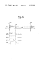
- FIG. 7 illustrates exemplary voltage waveforms produced by the circuits shown in FIGS. 10, 10a-10c and 11.
- FIG. 8 is a schematic diagram of a signal generating circuitry.
- FIG. 8a illustrates exemplary voltage waveforms generated by the circuitry illustrated in FIG. 8.
- FIG. 9 is a schematic diagram of a shorting control circuit.
- FIG. 10 illustrates the manner in which FIGS. 10a-10c should be arranged.
- FIGS. 10a-10c are schematic diagrams of a cylinder selection circuit.
- FIG. 11 illustrates a schematic diagram of a signal generating circuitry.
- an exemplary V-8 internal combustion engine 11 is capable of being diagnosed by a prior art Sun Electric Model 2001 Engine Analyzer 13.
- Analyzer 13 is described in detail in U.S. Pat. No. 4,125,894 issued to Cashel et al on Nov. 14, 1978.
- the Cashel Patent is incorporated herein by reference to indicate the analyzer environment in which the preferred embodiment of the present invention may be utilized.
- a plurality of engine monitoring leads 15 are connected to engine 11 at a plurality of locations for retrieving electrical signals and exhaust gas samples indicative of test data to be received by analyzer 13 for processing.
- Analyzer 13 includes a cathode ray tube (CRT) 17 for visually displaying various engine operating parameters and analysis information to the mechanic operator as the operator conducts different operating test sequences on the engine 11, as described in the Cashel Patent.
- CTR cathode ray tube
- Engine 11 comprises cylinders or ignition chambers 19-26 which are fitted with sparkplugs or igniters 19a-26a (19a-22a are shown). Sparkplugs 19A-26A are connected to a distributor 27 by sparkplug leads 19 L-26 L (19 L being shown).
- Distributor 27 includes a rotor (not shown) which distributes high voltage ignition signals to each of the sparkplugs in a defined sequence. The rotor receives high voltage ignition signals from a coil assembly 29 comprising a primary coil (not shown) which is magnetically coupled to a secondary coil (not shown). Voltage signals are generated in the primary coil by an 8-sided cam (not shown) which is mechanically rotated in synchronism with engine 11 in order to periodically open and close contact points (not shown). The primary coil voltage induces in the secondary coil high voltage ignition or firing signals or pulses which fire the sparkplugs sequentially.
- engine 11 has been described with a conventional mechanical contact point ignition system, it should be understood that the present invention may be used to diagnose engines having more sophisticated ignition systems in which electronic or semiconductor switches are used in place of mechanical contacts.
- a preferred embodiment of the present invention may be incorporated into analyzer 13 for diagnosing an engine of the above-described type.
- the preferred embodiment is illustrated in block form in FIG. 2.
- the operating condition of the engine is monitored by a primary pickup 31, a CYL No. 1 pickup 33 and a signal conditioning circuitry 35 for generating a plurality of timing signals along a conductor bus 37.
- the timing signals are fed to a signal preprocessor circuit 39 which controls a cylinder fire inhibit circuit 41, for selectively inhibiting one or more selected cylinders of the engine from firing. Cylinder firing inhibition is controlled by preprocessor circuit 39 in accordance with the timing signals generated along conductor bus 37.
- the exhaust gas from engine 11 is monitored by an exhaust probe 43 for generating data along a conductor bus 53, representative of the quantity of one or more combustion by-products in the exhaust gas.
- An exhaust gas analyzer 47, a gain attenuator 49 and an analog multiplexer/A-to-D converter 45 serve to transform the response of probe 43 to data signals for transmission to a central processing unit (CPU) 51 via a digital bus 53.
- CPU central processing unit
- CPU 51 controls the operation of signal preprocessor circuit 39 for inhibiting select cylinders from firing in order to retrieve pertinent data signals from analog multiplexer/A-to-D converter 45.
- the CPU processes the retrieved data signals for generating display signals for transmission to a video display circuit 55 for generating a visual display on CRT 17 of exhaust emissions analysis data.
- CPU 51 controls the overall system processing and management of the various operations of the preferred embodiment of the present invention. As will suggest itself, CPU 51 may be utilized to control other engine test procedures as described in the Cashel Patent, and similiarly, the other components illustrated in FIG. 2 may be utilized for other functions as will suggest themselves.
- primary pickup 31 is a block diagram representation of a primary clip 61 (FIG. 1) which samples the engine primary signal via a lead 63, in conjunction with a lead 65 which is connected to chassis ground via a clip 67.
- the CYL No. 1 pickup 33 is a block diagram representation of a clamp-on trigger pick-up 69 (FIG. 1) which is normally clipped around a sparkplug lead for the number 1 cylinder (e.g., lead 19L).
- Primary pickup 31 (FIG. 2) and CYL No. 1 pickup 33 provide signals to signal conditioning circuitry 35 for generating a pulse at the time the No. 1 cylinder of the engine is fired and for generating a pulse at the time of firing of each of the cylinders of the engine.
- FIG. 3 of the Cashel patent is illustrated as FIG. 6 herein.
- a trigger generator 215 is used to generate an ENG SYNC* pulse at the time the no. 1 cylinder of the engine is fired.
- an asterisk (*) is used to identify the inverse or complement of a pulse or signal identified without an asterisk.
- the trigger generator comprises resistors 217-228, capacitors 234-239, transistors 240-243 and a diode 246, connected as shown.
- a 9 millisecond one-shot multivibrator 247 and a 1.3 millisecond one-shot multivibrator 249 are used to suppress noise which may be picked up on the input to the trigger generator.
- Output conductor 251 provides an ENG SYNC pulse when spark plug 19a is fired, and output conductors 252-253 each provide an ENG SYNC* pulse which is the complement of the ENG SYNC pulse.
- Transformer coils 256, 257 provide an input signal from CYL. #1 pick-up 33 (FIG. 2) via conductors 159, 159a, and an over-voltage protection is provided by a varactor 259.
- FIG. 7 illustrates exemplary primary ignition waveforms PRCYL #1, PRCYL #2 and PRCYL #8 which correspond with the primary ignition signals produced in order to fire spark plugs of the #1 cylinder, the #2 cylinder and the #8 cylinder, respectively. Additional ignition waveforms, of course, are produced by primary coil 29 in order to fire spark plugs 19A through 26A. Also shown in FIG. 7 are the ENG SYNC pulses produced by the circuitry shown in FIG. 6.
- FIGS. 5, 5a of the Cashel patent are shown as FIGS. 8 and 8a herein.
- the circuitry of FIG. 8 generates a DELAYED DWELL* pulse having a duration proportional to the time that the contact points of the engine are closed.
- the circuitry includes an input circuit 362 capable of conditioning signals from a positive or negative grounded battery system.
- Circuitry 362 comprises operational amplifiers 364, 365 each connected as a comparator circuit, as well as resistors 368-379, and capacitor 381 and diodes 383, 384, connected as shown.
- a conditioning circuit 390 processes signals from conventional as well as high energy ignition circuits by means of operational amplifiers 392, 393, respectively, each of which is connected as a comparator circuit.
- the conditioning circuit also includes NAND gates 395-397, resistors 400-418, capacitors 421-424, an inverter 426, input conductors 428, 429 and a one-shot multivibrator 430 connected to a diode 431.
- a stretching and delay circuit 434 includes transistors 436-438, an operational amplifier 440 connected as a comparator circuit, an inverter 444, resistors 448, 449, 451, 453-458, and capacitors 461-462, all connected as shown.
- Driver transistors 530-531 amplify the signals conducted to output conductors 550-551.
- the transistors are biased by resistors 537-540.
- the circuitry of FIG. 8 is basically used to condition the signals received from the automotive engine in order to provide a DELAYED DWELL pulse.
- the circuitry of FIG. 8 operates as follows:
- Waveform W12 (FIG. 8a) illustrates an exemplary primary voltage waveform of the type received from primary pick-up 31.
- Waveform W12 includes a firing line P20 generated at the time the engine contact points open in order to fire a spark plug.
- the line between points P20 and P21 on waveform W12 indicates a time period during which current is gapping across the spark plug.
- the contact points close in order to initiate the dwell portion of the ignition cycle.
- the dwell portion ends at point P21 when the contact points again open in order to fire another spark plug.
- Operational amplifiers 364, 365 are arranged to accommodate either a negative battery or positive battery ignition system, respectively.
- the amplifiers from input primary signal W12 remove many of the oscillations by means of a comparator technique.
- the inverting input of operational amplifier 365 may be biased approximately at voltage VT1 (see FIG. 8a).
- the output of operational amplifier 365 produces voltage waveform W13.
- Operational amplifiers 392 and 393 apply the same comparator technique as amplifiers 364 and 365 in order to convert waveform W13 into a signal more nearly resembling a pulse, such as voltage waveform W14.
- the inverting input of operational amplifier 392 can be set at approximately VT2 volts (See FIG. 8a). In this mode of operation, operational amplifier 392 produces an output voltage waveform W14.
- Operational amplifier 393 is used in connection with so-called high energy ignition (HEI) systems that produced higher voltages than conventional ignition systems. As a result, operational amplifier 393 is less sensitive than operational amplifier 392.
- HAI high energy ignition
- the output of amplifier 393 is connected to the input of one-shot 430 in order to produce an output voltage wave form W17.
- This voltage is used a noise blanking signal in order to produce a more nearly uniform pulse at the input of stretching and delay circuit 434.
- Monostable multivibrator 430 produces a pulse having a duration of approximately one millisecond. It has been found that a multivibrator of this type is needed in connection with certain models of vehicle ignition systems which have a particularly long dwell time period.
- NAND gates 394-397 select either the output of amplifier 392 or the output of amplifier 393 for conduction to circuit 434 depending on the state of conductor 429 which is operated from a switch on the front panel of analyzer 13.
- the switch may be set by the operator depending on whether a conventional system or a special high energy ignition system is being used in the vehicle being tested. (See FIG. 17a of the Cashel patent.)
- the output of transistor 436 is amplified by a transistor 437 and is delayed by a filter and delay circuit comprising resistors 457, 458 and capacitors 461, 462.
- the delay circuit delays the leading and trailing edges of voltage waveform W14 by approximately 600 microseconds in order to produce a voltage waveform W18.
- This voltage is amplified by operational amplifier 440 and transistor 438.
- the waveform and its inverse are transmitted over output conductors 550 and 551 as DELAYED DWELL and DELAYED DWELL* pulses, respectively.
- FIG. 7 shows the DELAYED DWELL signal.
- other circuitry configurations may be utilized for signal condition circuitry 35 which will generate timing signals along conductor bus 37 indicative of the time of cylinder number 1 firing and the time of each of the other cylinder firings.
- Cylinder fire inhibit circuit 41 is operable according to a digital input pulse fed along a conductor 71 for loading the engines points contacts near ground for preventing the primary and secondary coils from firing any sparkplugs.
- FIG. 6 of Cashel patent is illustrated as FIG. 9 herein.
- a shorting control circuit comprises a triac 562 having a gate 563 and current conducting terminals 564, 565.
- the triac is connected in series with a resistor 567.
- Gate 563 is driven by a transistor 568, as well as a diode 569, resistors 570-574 and a capacitor 576.
- Inverters 578, 579 provide the various signals with proper polarity.
- Triac 562 is switched to its conductive state whenever the signal on conductor 71 is switched to its logical one state (i.e., whenever a positive AUTO SHORT* pulse is received).
- the ignition contacts are shorted to ground (except for the low resistance of resistor 567 and triac 562), and the primary and secondary coils are prevented from firing spark plugs.
- Signal preprocessor circuit 39 receives timing signals over conductor bus 37 for determining the time for output of a pulse onto conductor 71 for inhibiting a select cylinder from firing. Signal preprocessor circuit 39 is controlled by CPU 51 for selecting the particular cylinders to be inhibited by the preprocessor circuit.
- signal preprocessor circuit 39 may take on different forms, as for example the circuitry described in the Cashel patent, for commanding cylinder inhibition of selected cylinders.
- FIGS. 13, 13a-13c of the Cashel patent are illustrated herein as FIGS. 10, 10a-10c, respectively.
- a counting and cylinder control system comprises a cylinder selection circuit 1402, a counter circuit 1412, and a decoder circuit 1417, together with additional components.
- cylinder selection circuit 1402 comprises input inverters 1404-1409.
- the inverters receive inputs from conductors 1438-1442 that are connected to resistors 1438a-1442a and capacitors 1438b-1442b, respectively.
- Input conductors 1438-1442 receive MOD 3 *, MOD 4 *, MOD 6 *, MOD 8 *, MOD 12 * signals from the front panel of analyzer 13 depending on whether the engine being tested has 3, 4, 6, 8 or 12 cylinders respectively.
- Counter circuit 1412 includes flip-flop type counters 1414-1416 which continuously count through states 0-7 without being reset, except when the circuit is initially connected to an operating engine. After the first pulse transmitted over conductor 1444 (ENG SYNC) is received, the counter circuit is not reset, but continually counts through states 0-7 at a rate determined by the pulses received on conductor 1445 (PRIM SYZD).
- ENG SYNC first pulse transmitted over conductor 1444
- the counter circuit is not reset, but continually counts through states 0-7 at a rate determined by the pulses received on conductor 1445 (PRIM SYZD).
- FIG. 11 is a portion of FIG. 14c of the Cashel patent.
- the circuitry of FIG. 11 includes a D-type flip-flop 1684, inverter 1712 and resistors 1719-1722.
- the DELAYED DWELL* signal is inverted by inverter 1712 and is synchronized by clock signals in flip-flop 1684 in order to produce the PRIM SYZD signals shown in FIG. 7.
- the PRIM SYZD signals are transmitted to conductor 1445 (FIG. 10a) in order to advance counters 1414-1416.
- the first ENG SYNC pulse resets counters 1414-1416, and thereafter, the counters continue to operate in response to the PRIM SYZD pulse without being reset.
- Decoder circuit 1417 (FIG. 10a) comprises AND gates 1418-1426, NOR gates 1428-1431, NAND gates 1433-1436 and an inverter 1437.
- the cylinder selection circuit 1402, counter circuit 1412 and decoder circuit 1417 are interconnected by conductors 1448-1461 through cables 1463, 1464.
- Output conductors 1470-1473 represent digital bit positions 0-3, respectively for purposes for determining the spark plug of the engine which is about to be fired.
- a latch 1478 receives binary information from data bus conductors BD0-BD3 (of digital bus 53).
- the circuitry of FIG. 10b further includes D-type flip-flops 1480-1483, a one shot multivibrator 1485, NOR gates 1487-1490, Exclusive OR gates 1492-1495, AND gates 1497-1500, inverters 1502-1503, resistors 1506-1510, a capacitor 1512, and output conductors 1514, 1516, 1517, 1520 and 1521.
- Exclusive OR gates 1492-1495 operate as comparators. When the binary number stored in latch 1478 is identical to the binary number represented on output conductors 1470-1473, the Exclusive OR gates cause AND gate 1498 to produce an output pulse. During the next clock pulse received over conductor 1521, the Q output of flip-flop 1482 is switched to its one state and remains in its one state until the binary number represented by conductors 1470-1473 is changed.
- AND gates 1524-1527 and a NOR gate 1529 are used to operate the remaining circuitry when an appropriate address in the form of binary data is received on address conductors AD2-AD7 (of digital bus 53).
- the system also includes logic gates 1530-1535, switches 1540-1545, and resistors 1550-1555.
- the circuitry can be used in order to manually introduce data into the data processor by means of manipulating the switches.
- Output conductors 1557-1558 connect the circuitry in the manner shown.
- CPU 51 issues a CYLINDER SELECT OUTPUT COMMAND shown in the following Table 7:
- signal preprocessor circuit 39 may comprise a slave microprocessor, as for example, a Motorola 6802 Microprocessor chip.
- CPU 51 addresses preprocessor circuit 39 and transmits an inhibit control data word to the preprocessor circuit via digital bus 53.
- the control data word carries information as to the particular cylinder number or numbers to be inhibited by the preprocessor circuit.
- the slave microprocessor monitors the timing information on conductor bus 37 for providing a pulse output along conductor 71 at the appropriate times in each engine firing cycle for inhibiting the selected cylinder as identified by the control data word from CPU 51.
- an uninhibit control data word may be transmitted to signal preprocessor circuit 39 which instructs the preprocessor circuit to discontinue cylinder inhibition, permitting the engine to run normally.
- the preprocessor circuit repeatedly places a pulse along conductor 71 at the time the selected cylinder is to fire in order to repetitively inhibit the selected cylinder until instructed otherwise by CPU 51.
- Signal preprocessor circuit 39 is a subassembly component manufactured by Sun Electric Corporation as Board #7001-120 which is used in various engine testers manufactured by Sun Electric Corporation.
- Exhaust gas analyzer 47 is connected to an exhaust probe 43 which is placed in the tail pipe assembly of the vehicle being tested.
- Analyzer 47 may be implemented by a variety of available devices which are capable of producing output voltages on a conductor bus 73 having amplitudes proportional to the amounts of a pollutant or other non-pollutant gas emitted from engine 11, as seen by probe 43.
- the preferred embodiment will be described with reference to measuring hydrocarbons (HC), however other products of combustion also may be measured, as for example, carbon monoxide (CO), nitric oxide (NO), nitrogen dioxide (NO 2 ), carbon dioxide (CO 2 ) and oxygen (O 2 ).
- An analyzer which may be utilized as exhaust gas analyzer 47 is the analyzer used in Sun Electric Model 2001 Analyzer (See the Cashel Patent). Such an analyzer measures n-hexane based hydrocarbons, which is preferred.
- a gain attenuator 49 is utilized to attenuate the analog signal developed from hydrocarbon measurements by analyzer 47.
- the analog signal for hydrocarbons passes along conductor bus 73 into analog multiplexer/A-to-D converter 45 and also passes via gain attenuator 49 to the converter 45.
- the use of gain attenuator 49 permits a high range of relative measurements of hydrocarbons, as great as ten thousand parts per million, as described hereinafter.
- Analog multiplexer/A-to-D converter 45 controls the analog signals developed along conductor bus 73 and the analog signals developed from gain attenuator 49 along a conductor 75, for systematically channeling the signals to a single analog-to-digital converter for changing the form of the signals to digital measurement signals. More particularly, either of the signals appearing on conductor bus 73 or conductor 75 is separately addressable by CPU 51 for channeling through the A-to-D converter for output onto digital bus 53.
- Data acquisition by CPU 51 may be performed in either of two modes, an automatic mode or a manual mode.
- an automatic mode data sampling and cylinder ignition inhibition are automatically controlled by the CPU in firing order sequence.
- the manual mode the operator selects and controls which cylinder, or cylinders, is to be inhibited at any given time.
- control switch panel 77 may comprise a keyboard and a control switch assembly similar to that disclosed in the Cashel patent.
- control switch panel 77 include set up switches which must be properly adjusted by the operator before the system is ready for operation, including a switch which informs CPU 51 as to the number of cylinders in the engine to be tested (see FIG. 17A and the associated description in the Cashel patent).
- control switch panel 77 is illustrated showing only cylinder select switches 79 and a # switch 81. As is understood, other control switches and the like may be included in control panel 77 in accordance with the particular type of analyzer within which the present invention is being utilized.
- Cylinder select switches 79 include 12 separately actuable switches, each of which being associated with a particular cylinder number, and a release switch for resetting the 12 switches.
- the cylinder select switches 79 are selectively actuable by the operator for selecting a particular cylinder to be inhibited.
- the # switch includes a single electrical switch which is actuable for indicating that the operator is instructing an automatic mode of operation.
- a digital I/O circuit 83 transforms the position of switches 79, 81 into a digital output signal for placement onto digital bus 53 in order to communicate operator instructions to CPU 51.
- CPU 51 will monitor the digital I/O circuit 83 until a start of the test is detected.
- the automatic test is started when the operator presses # switch 81.
- the manual test is started when any cylinder or combination of cylinders is selected via the cylinder select switches 79.
- CPU 51 will control the sequencing of all events via digital bus 53.
- exhaust gas analyzer 47 samples the engine exhaust gas via exhaust probe 43 and generates voltages which are representative of combustion by-product levels. These voltages are fed into the analog multiplexer/A-to-D converter 45 and the hydrocarbon voltages are also fed into gain attenuator 49.
- CPU 51 will command analog multiplexer/A-to-D converter 45 to select and sample an appropriate voltage for output to CPU 51.
- CPU 51 then processes all information gathered and displays the results on the CRT 17.
- Signal preprocessor circuit 39 continuously monitors engine conditions while CPU 51 is controlling the sequencing of the test. When CPU 51 decides it is time to inhibit a cylinder from firing, it accordingly commands signal preprocessor circuit 39 to inhibit a select cylinder via cylinder fire inhibit circuit 41.
- CPU 51 performs a number of steps 85-107 for conducting the automatic test mode of operation. Initial values of exhaust gas concentrations are sampled and saved at step 85 prior to cylinder inhibition. The first cylinder is inhibited from firing at step 87. The inhibition is maintained at step 89 long enough for the engine RPM to settle to a new level.
- the CPU controls the time of inhibition by a discrete time delay which may be fixed at a value dependent on the RPM of the engine during the test, i.e. the RPM of the engine running without cylinder inhibition. The maximum time of cylinder inhibition is preferred to be 8 seconds.
- step 91 the engine firing inhibition is removed allowing the engine to run normally once again (step 91).
- the gas measuring system will then begin to see the effects of the cylinder inhibition.
- the changing emissions levels are monitored at step 93 and the maximum emissions levels are stored.
- the CPU delays the next cylinder inhibition at step 95 until either: (1) the rate of change of exhaust by-product value has subsided enough to indicate that the effects of the previous cylinder inhibition have died out, or (2) a sufficient amount of time has elapsed to insure that the effects of the previous cylinder inhibition are negligible. This will insure that sampling periods are synchronized with cylinder inhibition periods for all lengths of vehicle exhaust systems.
- the exhaust by-product value is monitored for at least 4 seconds (minimum delay) until the value falls to 1/2 its peak value or until 12 seconds (maximum delay) has lapsed, whichever is shorter, for providing the delay at step 95.
- step 97 indicates that each cylinder has been inhibited once, cylinder No. 1 is inhibited a second time via step 99.
- the CPU will collect the following data: (a) an initial sampling of the emissions level with the engine running normally; (b) a sampling of emissions levels with the engine running with each cylinder individually inhibited, beginning with cylinder No. 1; and (c) a second sampling of emissions levels with the engine running with cylinder No. 1 inhibited.
- step 101 the data samples are corrected for gas build-up at step 101 using a linear correction algorithm, as described hereinafter. Corrected samples are then processed at step 103 (described hereinafter) and thereafter the processed data is displayed as analysis data via step 105.
- the operator controls the sequencing of the data acquisition cycle.
- the engine must be allowed to reach a steady state condition at a desired RPM prior to the test beginning.
- the operator initiates the test by selecting one or more cylinders to be inhibited via the cylinder select switches 79.
- CPU 51 reads the emissions levels and stores the same as a base reading.
- the emissions level changes for the inhibited cylinder will not be computed and displayed by the CPU until the operator changes the cylinders to be inhibited, either by selecting different cylinders via cylinder select switches 79 or by selecting no cylinders by the actuation of the cylinder release button on panel 77. Once the operator changes the cylinders to be inhibited, the current emissions levels will be compared to the base levels stored previously and the amount of change will be computed and displayed as described hereinafter.
- the raw data received from analog multiplexer/A-to-D converter 45 must be processed before it is displayed to the operator on CRT 17.
- Two algorithms are applied to the data, one algorithm is for linear correction (automatic mode only) and the other algorithm is for processing the emissions change values to display values.
- the exhaust gas measuring system generates a voltage which represents the concentration of a certain by-product in the gas. Several such voltages are generated to represent the concentration of several different by-products.
- the correlation between the output voltage of the exhaust gas measuring system and the actual gas concentration is not a simple function; CPU 51 utilizes a stored lookup table for determining the absolute value of a gas concentration for a given voltage output from analyzer 47.
- conventional gas analyzer equipment for hydrocarbons is designed to indicate up to 2000 parts per million (ppm) of hydrocarbons in the gas being analyzed.
- the output of such conventional analyzers typically are set at a voltage at a full scale reading of 2000 ppm, which is near the full scale input of the A-to-D converter 45 to optimize display resolution.
- the gas measuring system of the presently described embodiment is designed so that the hydrocarbon concentation range corresponding to a 0 to 5 volt output is adequate for all the normal 0-2000 ppm range emissions testing.
- the hydrocarbon emissions levels may exceed the useful limit of the measuring system. If the measuring system puts out a voltage in the range of 5 to 12 volts, for example, the A-to-D converter 45 may be overranged, and may give an incorrect digital output.
- the cylinder performance test of the preferred embodiment is based upon comparitive changes in emissions levels and not absolute values, therefore, it is not necessary to compute absolute values. Only a magnitude indication of hydrocarbon change is displayed making it unnecessary to interpret absolute hydrocarbon levels for voltages in the 5-12 voltage range, as described hereinafter.
- the analog voltage from the exhaust gas measuring system may have to be attenuated, as is the case with measuring hydrocarbons. This serves to extend the operating range of gas analyzer 47, permitting the analog-to-digital converter 45 to process signals that would normally be too large for it to handle.
- the first reading taken uses the attenuated voltage from gain attenuator 49 and also uses the normal gas measuring voltage appearing on conductor bus 73. These two voltage readings may be utilized for relating the attenuated voltage directly to an emission level. If the base gas reading taken by normal means is beyond the usable range of the measuring system, then the base gas reading is arbitrarily set to the maximum usable reading the system can generate (2000 ppm). This is to insure that there will always be one known point to reference the attenuated voltage scale to the normal voltage scale.
- the available data used by CPU 51 to perform each calculation comprises one base reading in ppm taken at the beginning of the test, one attenuated voltage reading taken at the beginning of the test and one attenuated voltage reading taken for each cylinder inhibition.
- the base reading (in ppm) is subtracted from each of the calculated per cylinder relative emissions levels (in ppm) to yield a relative change. Although this relative change is displayed in proper units (ppm) for the gas of interest being measured, the actual numeric values do not represent correct absolute measurement. The numbers are intended only to show relative differences between per cylinder emission levels.
- FIG. 4A illustrates an emissions level versus time plot for an ideal gas measuring system.
- the emissions level begins to rise until a maximum "pollution" level is reached.
- the readings will begin to fall again. Since the test described herein is only concerned with maximum values read, it is not necessary to allow the falling values to reach their absolute minimum.
- the next cylinder in the sequence may be inhibited before this minimum occurs, preferably at 1/2 the peak value as stated above. However, any gas that has not been completely flushed from the system may make the next reading look higher than it actually is.
- FIG. 4B shows the final effect of such gas build-up.
- the exhaust by-product introduced for each cylinder period becomes greater.
- cylinder No. 1 is inhibited and retested immediately after the last cylinder in the sequence is tested. This reading should be the same as the reading taken at the first time cylinder No. 1 was inhibited, since it is taken under the same conditions. If it is not, the difference is due to gas build-up in the system.
- Cylinder No. 1 no error first time.
- FIG. 5 illustrates a general format to be displayed on the CRT screen of the CRT 17. Individual cylinder numbers are displayed in a vertical column 109 in association with a parallel column 111 of numbers representing a hydrocarbon change which occurred when its respective associated cylinder number was inhibited from firing.
- FIG. 5 shows the HC change data as a plurality of X's. These X's represent the processed readings which are generated by CPU 51 during the cylinder analysis emission test.
- other columns of data for by-products other than hydrocarbons may be included in row-association with the cylinder numbers of column 109.
- the absolute value of hydrocarbons is displayed on the CRT screen at 113 in units of parts per million.
- CPU 51 monitors the voltage level along conductor bus 73 for hydrocarbons and converts the voltage level to a hydrocarbon absolute value for display at 113 on the CRT screen.
- an upward pointing arrow ( ⁇ ) is displayed in the numeric position (shown with X's) for indicating that the hydrocarbon concentration is exceeding the level capable of being accurately interpreted by exhaust gas analyzer 47.
- the hydrocarbon ppm display 113 is continuously updated by CPU 51 so that the operator can monitor the hydrocarbon level as the level climbs to a peak and then descends after a particular cylinder has been inhibited, assuming of course that the hydrocarbon level does not exceed 2000 ppm.
Landscapes
- Chemical & Material Sciences (AREA)
- Engineering & Computer Science (AREA)
- Combustion & Propulsion (AREA)
- Physics & Mathematics (AREA)
- General Physics & Mathematics (AREA)
- Health & Medical Sciences (AREA)
- Emergency Medicine (AREA)
- Combined Controls Of Internal Combustion Engines (AREA)
- Testing Of Engines (AREA)
Abstract
Description
              TABLE 7
______________________________________
AD2  AD3    AD4    AD5  AD6  AD7  BD15   BD0-BD3
______________________________________
1    0      1      1    0    1    Short=1
                                         No. of Cylinder
______________________________________
Claims (23)
Priority Applications (3)
| Application Number | Priority Date | Filing Date | Title |
|---|---|---|---|
| US06/140,586 US4328546A (en) | 1980-04-15 | 1980-04-15 | Apparatus for evaluating the performance of an internal combustion engine using exhaust gas emission data |
| CA000372825A CA1146221A (en) | 1980-04-15 | 1981-03-12 | Apparatus for evaluating the performance of an internal combustion engine using exhaust gas emission data |
| CA000420409A CA1163678A (en) | 1980-04-15 | 1983-01-27 | Apparatus for evaluating the performance of an internal combustion engine using exhaust gas emission data |
Applications Claiming Priority (1)
| Application Number | Priority Date | Filing Date | Title |
|---|---|---|---|
| US06/140,586 US4328546A (en) | 1980-04-15 | 1980-04-15 | Apparatus for evaluating the performance of an internal combustion engine using exhaust gas emission data |
Publications (1)
| Publication Number | Publication Date |
|---|---|
| US4328546A true US4328546A (en) | 1982-05-04 |
Family
ID=22491920
Family Applications (1)
| Application Number | Title | Priority Date | Filing Date |
|---|---|---|---|
| US06/140,586 Expired - Lifetime US4328546A (en) | 1980-04-15 | 1980-04-15 | Apparatus for evaluating the performance of an internal combustion engine using exhaust gas emission data |
Country Status (2)
| Country | Link |
|---|---|
| US (1) | US4328546A (en) |
| CA (1) | CA1146221A (en) |
Cited By (18)
| Publication number | Priority date | Publication date | Assignee | Title |
|---|---|---|---|---|
| US4509488A (en) * | 1981-07-23 | 1985-04-09 | Daimler-Benz Aktiengesellschaft | Process and apparatus for intermittent control of a cyclically operating internal combustion engine |
| US4602127A (en) * | 1984-03-09 | 1986-07-22 | Micro Processor Systems, Inc. | Diagnostic data recorder |
| US4853850A (en) * | 1985-09-10 | 1989-08-01 | Krass Jr James E | Vehicle computer diagnostic interface apparatus |
| US4881183A (en) * | 1988-03-25 | 1989-11-14 | Sun Electric Corporation | Method and apparatus for emission testing |
| US4924095A (en) * | 1987-06-02 | 1990-05-08 | West Lodge Research | Remote gas analyzer for motor vehicle exhaust emissions surveillance |
| US5040117A (en) * | 1989-09-25 | 1991-08-13 | Industrial Technology Research Institute | Automatically adjusting the emissions from an idling engine |
| US5099680A (en) * | 1990-05-03 | 1992-03-31 | Sensors, Inc. | Method of analyzing vehicle emissions and in-flight gas analysis apparatus |
| US5263850A (en) * | 1992-02-05 | 1993-11-23 | Boston Thermal Energy Corporation | Emission control system for an oil-fired combustion process |
| US5431042A (en) * | 1994-03-10 | 1995-07-11 | General Motors Corporation | Engine emissions analyzer |
| US5481906A (en) * | 1993-06-30 | 1996-01-09 | Mitsubishi Jidosha Kogyo Kabushiki Kaisha | Fault diagnosis apparatus and method for vehicle control system |
| US5550737A (en) * | 1993-11-05 | 1996-08-27 | Environmental Systems Products, Inc. | Method for analysis of vehicle performance characteristics |
| US5639957A (en) * | 1995-10-12 | 1997-06-17 | Snap-On Technologies, Inc. | Method and apparatus for performing modal mass analysis of exhaust gas from motor vehicle |
| US5711021A (en) * | 1995-08-07 | 1998-01-20 | Snap-On Technologies, Inc. | Method for graphically displaying vehicle test data |
| US6079251A (en) * | 1998-02-17 | 2000-06-27 | Noranda Inc. | Diesel exhaust analysis system and method of using the same |
| EP1014072A2 (en) * | 1998-12-21 | 2000-06-28 | Robert Bosch Gmbh | Cylinder comparing test procedure for combustion engines with injection, in particular for vehicle engines |
| US20080276407A1 (en) * | 2007-05-09 | 2008-11-13 | Irobot Corporation | Compact Autonomous Coverage Robot |
| US20130124033A1 (en) * | 2011-11-10 | 2013-05-16 | Horiba, Ltd. | Test System |
| EP2941804A4 (en) * | 2013-01-05 | 2017-06-28 | MTD products Inc | Alternator overvoltage protection circuit |
Citations (5)
| Publication number | Priority date | Publication date | Assignee | Title |
|---|---|---|---|---|
| US3788129A (en) * | 1971-06-24 | 1974-01-29 | Sun Electric Corp | Select signal engine diagnosing apparatus |
| US3940977A (en) * | 1974-07-17 | 1976-03-02 | Sun Electric Corporation | Signal disabling engine diagnosing apparatus |
| US3998095A (en) * | 1972-11-15 | 1976-12-21 | Clayton Manufacturing Company | Method and apparatus for quickly evaluating engine exhaust gas emissions |
| US4125894A (en) * | 1975-12-16 | 1978-11-14 | Sun Electric Corporation | Engine test and display apparatus |
| US4143635A (en) * | 1976-12-08 | 1979-03-13 | Nissan Motor Company, Limited | Exhaust gas recirculated engine with variable cylinder disablement control |
-
1980
- 1980-04-15 US US06/140,586 patent/US4328546A/en not_active Expired - Lifetime
-
1981
- 1981-03-12 CA CA000372825A patent/CA1146221A/en not_active Expired
Patent Citations (5)
| Publication number | Priority date | Publication date | Assignee | Title |
|---|---|---|---|---|
| US3788129A (en) * | 1971-06-24 | 1974-01-29 | Sun Electric Corp | Select signal engine diagnosing apparatus |
| US3998095A (en) * | 1972-11-15 | 1976-12-21 | Clayton Manufacturing Company | Method and apparatus for quickly evaluating engine exhaust gas emissions |
| US3940977A (en) * | 1974-07-17 | 1976-03-02 | Sun Electric Corporation | Signal disabling engine diagnosing apparatus |
| US4125894A (en) * | 1975-12-16 | 1978-11-14 | Sun Electric Corporation | Engine test and display apparatus |
| US4143635A (en) * | 1976-12-08 | 1979-03-13 | Nissan Motor Company, Limited | Exhaust gas recirculated engine with variable cylinder disablement control |
Cited By (20)
| Publication number | Priority date | Publication date | Assignee | Title |
|---|---|---|---|---|
| US4509488A (en) * | 1981-07-23 | 1985-04-09 | Daimler-Benz Aktiengesellschaft | Process and apparatus for intermittent control of a cyclically operating internal combustion engine |
| US4602127A (en) * | 1984-03-09 | 1986-07-22 | Micro Processor Systems, Inc. | Diagnostic data recorder |
| US4853850A (en) * | 1985-09-10 | 1989-08-01 | Krass Jr James E | Vehicle computer diagnostic interface apparatus |
| US4924095A (en) * | 1987-06-02 | 1990-05-08 | West Lodge Research | Remote gas analyzer for motor vehicle exhaust emissions surveillance |
| US4881183A (en) * | 1988-03-25 | 1989-11-14 | Sun Electric Corporation | Method and apparatus for emission testing |
| US5040117A (en) * | 1989-09-25 | 1991-08-13 | Industrial Technology Research Institute | Automatically adjusting the emissions from an idling engine |
| US5099680A (en) * | 1990-05-03 | 1992-03-31 | Sensors, Inc. | Method of analyzing vehicle emissions and in-flight gas analysis apparatus |
| US5263850A (en) * | 1992-02-05 | 1993-11-23 | Boston Thermal Energy Corporation | Emission control system for an oil-fired combustion process |
| US5481906A (en) * | 1993-06-30 | 1996-01-09 | Mitsubishi Jidosha Kogyo Kabushiki Kaisha | Fault diagnosis apparatus and method for vehicle control system |
| US5550737A (en) * | 1993-11-05 | 1996-08-27 | Environmental Systems Products, Inc. | Method for analysis of vehicle performance characteristics |
| US5431042A (en) * | 1994-03-10 | 1995-07-11 | General Motors Corporation | Engine emissions analyzer |
| US5711021A (en) * | 1995-08-07 | 1998-01-20 | Snap-On Technologies, Inc. | Method for graphically displaying vehicle test data |
| US5639957A (en) * | 1995-10-12 | 1997-06-17 | Snap-On Technologies, Inc. | Method and apparatus for performing modal mass analysis of exhaust gas from motor vehicle |
| US6079251A (en) * | 1998-02-17 | 2000-06-27 | Noranda Inc. | Diesel exhaust analysis system and method of using the same |
| EP1014072A2 (en) * | 1998-12-21 | 2000-06-28 | Robert Bosch Gmbh | Cylinder comparing test procedure for combustion engines with injection, in particular for vehicle engines |
| EP1014072A3 (en) * | 1998-12-21 | 2000-12-06 | Robert Bosch Gmbh | Cylinder comparing test procedure for combustion engines with injection, in particular for vehicle engines |
| US20080276407A1 (en) * | 2007-05-09 | 2008-11-13 | Irobot Corporation | Compact Autonomous Coverage Robot |
| US20130124033A1 (en) * | 2011-11-10 | 2013-05-16 | Horiba, Ltd. | Test System |
| US9140675B2 (en) * | 2011-11-10 | 2015-09-22 | Horiba, Ltd. | Test system |
| EP2941804A4 (en) * | 2013-01-05 | 2017-06-28 | MTD products Inc | Alternator overvoltage protection circuit |
Also Published As
| Publication number | Publication date |
|---|---|
| CA1146221A (en) | 1983-05-10 |
Similar Documents
| Publication | Publication Date | Title |
|---|---|---|
| US4328546A (en) | Apparatus for evaluating the performance of an internal combustion engine using exhaust gas emission data | |
| US4006403A (en) | Engine performance analyzer | |
| US4418388A (en) | Engine waveform pattern analyzer | |
| US5396176A (en) | Combustion condition diagnosis utilizing multiple sampling of ionic current | |
| US5296869A (en) | Digital engine analyzer | |
| US4425791A (en) | Computer based engine analyzer with hardware cylinder counter | |
| US4394742A (en) | Engine generated waveform analyzer | |
| US5245324A (en) | Digital engine analyzer | |
| EP0081353A2 (en) | Engine analyser with digital waveform display | |
| US4812979A (en) | Method and apparatus for analyzing the performance of the electronic ignition of an internal combustion engine | |
| US4027532A (en) | Compression testing apparatus | |
| US5160892A (en) | Engine analyzer waveform display with a buffer region | |
| CA2323104C (en) | Apparatus and method for testing an ignition coil and spark plug | |
| US5247287A (en) | Digital engine analyzer | |
| USRE29984E (en) | Engine ignition and power analyzer | |
| US4373186A (en) | Matrix method and apparatus for engine analysis | |
| US5258753A (en) | Digital engine analyzer | |
| US4472779A (en) | Engine timing apparatus for use in testing | |
| US4126037A (en) | Compression test using battery voltage waveform during cranking | |
| US4625546A (en) | Cylinder power balance diagnostic apparatus for internal combustion engine | |
| US4101822A (en) | Instrument for testing a breakerless ignition system | |
| EP0573569B1 (en) | Internal combustion engine mapping apparatus and method | |
| CA1163678A (en) | Apparatus for evaluating the performance of an internal combustion engine using exhaust gas emission data | |
| RU2007610C1 (en) | Device for diagnostics of diesel engine systems | |
| USRE31656E (en) | Engine ignition and power analyzer |
Legal Events
| Date | Code | Title | Description |
|---|---|---|---|
| STCF | Information on status: patent grant |
Free format text: PATENTED CASE |
|
| AS | Assignment |
Owner name: HARRIS TRUST AND SAVINGS BANK AN IL CORP., ILLINOI Free format text: SECURITY INTEREST;ASSIGNOR:SUN ELECTRIC CORPORATION, A CORP. OF DE;REEL/FRAME:006190/0663 Effective date: 19920724 |
|
| AS | Assignment |
Owner name: FOOTHILL CAPITAL CORPORATION A CA CORP., CALIFORN Free format text: SECURITY INTEREST;ASSIGNOR:SUN ELECTRIC CORPORATION A DE CORP.;REEL/FRAME:006225/0658 Effective date: 19920724 |
|
| AS | Assignment |
Owner name: SUN ELECTRIC CORPORATION, ILLINOIS Free format text: RELEASE AND TERMINATION OF COLLATERAL PATENT AND TRADEMARK ASSIGNMENT;ASSIGNOR:FOOTHILL CAPITAL CORPORATION;REEL/FRAME:007644/0191 Effective date: 19930223 Owner name: SUN ELECTRIC CORPORATION, ILLINOIS Free format text: RELEASE BY SECURED PARTY;ASSIGNOR:HARRIS BANK;REEL/FRAME:007644/0179 Effective date: 19921022 |
|
| AS | Assignment |
Owner name: SNAP-ON TOOLS COMPANY, WISCONSIN Free format text: ASSIGNMENT OF ASSIGNORS INTEREST;ASSIGNOR:SUN ELECTRIC CORPORATION;REEL/FRAME:007881/0521 Effective date: 19951229 |