US11786327B2 - Tele-operated forceps-driver variable stiffness master device - Google Patents
Tele-operated forceps-driver variable stiffness master device Download PDFInfo
- Publication number
- US11786327B2 US11786327B2 US17/029,286 US202017029286A US11786327B2 US 11786327 B2 US11786327 B2 US 11786327B2 US 202017029286 A US202017029286 A US 202017029286A US 11786327 B2 US11786327 B2 US 11786327B2
- Authority
- US
- United States
- Prior art keywords
- deformable membrane
- master
- force
- gripper
- tele
- Prior art date
- Legal status (The legal status is an assumption and is not a legal conclusion. Google has not performed a legal analysis and makes no representation as to the accuracy of the status listed.)
- Active, expires
Links
Images


Classifications
-
- A—HUMAN NECESSITIES
- A61—MEDICAL OR VETERINARY SCIENCE; HYGIENE
- A61B—DIAGNOSIS; SURGERY; IDENTIFICATION
- A61B34/00—Computer-aided surgery; Manipulators or robots specially adapted for use in surgery
- A61B34/30—Surgical robots
- A61B34/35—Surgical robots for telesurgery
-
- A—HUMAN NECESSITIES
- A61—MEDICAL OR VETERINARY SCIENCE; HYGIENE
- A61B—DIAGNOSIS; SURGERY; IDENTIFICATION
- A61B17/00—Surgical instruments, devices or methods, e.g. tourniquets
- A61B17/00234—Surgical instruments, devices or methods, e.g. tourniquets for minimally invasive surgery
-
- A—HUMAN NECESSITIES
- A61—MEDICAL OR VETERINARY SCIENCE; HYGIENE
- A61B—DIAGNOSIS; SURGERY; IDENTIFICATION
- A61B17/00—Surgical instruments, devices or methods, e.g. tourniquets
- A61B17/28—Surgical forceps
- A61B17/29—Forceps for use in minimally invasive surgery
-
- A—HUMAN NECESSITIES
- A61—MEDICAL OR VETERINARY SCIENCE; HYGIENE
- A61B—DIAGNOSIS; SURGERY; IDENTIFICATION
- A61B34/00—Computer-aided surgery; Manipulators or robots specially adapted for use in surgery
- A61B34/30—Surgical robots
- A61B34/37—Master-slave robots
-
- A—HUMAN NECESSITIES
- A61—MEDICAL OR VETERINARY SCIENCE; HYGIENE
- A61B—DIAGNOSIS; SURGERY; IDENTIFICATION
- A61B34/00—Computer-aided surgery; Manipulators or robots specially adapted for use in surgery
- A61B34/70—Manipulators specially adapted for use in surgery
- A61B34/74—Manipulators with manual electric input means
-
- A—HUMAN NECESSITIES
- A61—MEDICAL OR VETERINARY SCIENCE; HYGIENE
- A61B—DIAGNOSIS; SURGERY; IDENTIFICATION
- A61B34/00—Computer-aided surgery; Manipulators or robots specially adapted for use in surgery
- A61B34/70—Manipulators specially adapted for use in surgery
- A61B34/76—Manipulators having means for providing feel, e.g. force or tactile feedback
-
- B—PERFORMING OPERATIONS; TRANSPORTING
- B25—HAND TOOLS; PORTABLE POWER-DRIVEN TOOLS; MANIPULATORS
- B25J—MANIPULATORS; CHAMBERS PROVIDED WITH MANIPULATION DEVICES
- B25J3/00—Manipulators of master-slave type, i.e. both controlling unit and controlled unit perform corresponding spatial movements
- B25J3/04—Manipulators of master-slave type, i.e. both controlling unit and controlled unit perform corresponding spatial movements involving servo mechanisms
-
- A—HUMAN NECESSITIES
- A61—MEDICAL OR VETERINARY SCIENCE; HYGIENE
- A61B—DIAGNOSIS; SURGERY; IDENTIFICATION
- A61B17/00—Surgical instruments, devices or methods, e.g. tourniquets
- A61B2017/00017—Electrical control of surgical instruments
- A61B2017/00022—Sensing or detecting at the treatment site
-
- A—HUMAN NECESSITIES
- A61—MEDICAL OR VETERINARY SCIENCE; HYGIENE
- A61B—DIAGNOSIS; SURGERY; IDENTIFICATION
- A61B17/00—Surgical instruments, devices or methods, e.g. tourniquets
- A61B17/00234—Surgical instruments, devices or methods, e.g. tourniquets for minimally invasive surgery
- A61B2017/00292—Surgical instruments, devices or methods, e.g. tourniquets for minimally invasive surgery mounted on or guided by flexible, e.g. catheter-like, means
- A61B2017/003—Steerable
-
- A—HUMAN NECESSITIES
- A61—MEDICAL OR VETERINARY SCIENCE; HYGIENE
- A61B—DIAGNOSIS; SURGERY; IDENTIFICATION
- A61B17/00—Surgical instruments, devices or methods, e.g. tourniquets
- A61B2017/00367—Details of actuation of instruments, e.g. relations between pushing buttons, or the like, and activation of the tool, working tip, or the like
- A61B2017/00398—Details of actuation of instruments, e.g. relations between pushing buttons, or the like, and activation of the tool, working tip, or the like using powered actuators, e.g. stepper motors, solenoids
-
- A—HUMAN NECESSITIES
- A61—MEDICAL OR VETERINARY SCIENCE; HYGIENE
- A61B—DIAGNOSIS; SURGERY; IDENTIFICATION
- A61B17/00—Surgical instruments, devices or methods, e.g. tourniquets
- A61B17/28—Surgical forceps
- A61B17/29—Forceps for use in minimally invasive surgery
- A61B17/2909—Handles
- A61B2017/2912—Handles transmission of forces to actuating rod or piston
-
- A—HUMAN NECESSITIES
- A61—MEDICAL OR VETERINARY SCIENCE; HYGIENE
- A61B—DIAGNOSIS; SURGERY; IDENTIFICATION
- A61B17/00—Surgical instruments, devices or methods, e.g. tourniquets
- A61B17/28—Surgical forceps
- A61B17/29—Forceps for use in minimally invasive surgery
- A61B2017/2926—Details of heads or jaws
- A61B2017/2932—Transmission of forces to jaw members
-
- A—HUMAN NECESSITIES
- A61—MEDICAL OR VETERINARY SCIENCE; HYGIENE
- A61B—DIAGNOSIS; SURGERY; IDENTIFICATION
- A61B34/00—Computer-aided surgery; Manipulators or robots specially adapted for use in surgery
- A61B34/30—Surgical robots
- A61B2034/305—Details of wrist mechanisms at distal ends of robotic arms
- A61B2034/306—Wrists with multiple vertebrae
-
- A—HUMAN NECESSITIES
- A61—MEDICAL OR VETERINARY SCIENCE; HYGIENE
- A61B—DIAGNOSIS; SURGERY; IDENTIFICATION
- A61B90/00—Instruments, implements or accessories specially adapted for surgery or diagnosis and not covered by any of the groups A61B1/00 - A61B50/00, e.g. for luxation treatment or for protecting wound edges
- A61B90/06—Measuring instruments not otherwise provided for
- A61B2090/062—Measuring instruments not otherwise provided for penetration depth
-
- A—HUMAN NECESSITIES
- A61—MEDICAL OR VETERINARY SCIENCE; HYGIENE
- A61B—DIAGNOSIS; SURGERY; IDENTIFICATION
- A61B90/00—Instruments, implements or accessories specially adapted for surgery or diagnosis and not covered by any of the groups A61B1/00 - A61B50/00, e.g. for luxation treatment or for protecting wound edges
- A61B90/06—Measuring instruments not otherwise provided for
- A61B2090/064—Measuring instruments not otherwise provided for for measuring force, pressure or mechanical tension
-
- A—HUMAN NECESSITIES
- A61—MEDICAL OR VETERINARY SCIENCE; HYGIENE
- A61B—DIAGNOSIS; SURGERY; IDENTIFICATION
- A61B90/00—Instruments, implements or accessories specially adapted for surgery or diagnosis and not covered by any of the groups A61B1/00 - A61B50/00, e.g. for luxation treatment or for protecting wound edges
- A61B90/06—Measuring instruments not otherwise provided for
- A61B2090/067—Measuring instruments not otherwise provided for for measuring angles
-
- B—PERFORMING OPERATIONS; TRANSPORTING
- B25—HAND TOOLS; PORTABLE POWER-DRIVEN TOOLS; MANIPULATORS
- B25J—MANIPULATORS; CHAMBERS PROVIDED WITH MANIPULATION DEVICES
- B25J13/00—Controls for manipulators
- B25J13/08—Controls for manipulators by means of sensing devices, e.g. viewing or touching devices
- B25J13/081—Touching devices, e.g. pressure-sensitive
- B25J13/082—Grasping-force detectors
Definitions
- the present disclosure relates to a tele-operated forceps-driver variable stiffness master device, and more particularly, to a tele-operated forceps-driver variable stiffness master device capable of feeding back the sensation of a forceps driver being operated while controlling the forceps driver.
- a surgical robot end effector for driving forceps is well known.
- a forceps driver is a device in which two wheels positioned on top of linear sliders driven by an electric motor operate in the lengthwise direction of forceps, and grip of the forceps is enabled by the operation.
- the forceps driver is difficult to achieve precise measurement and fine control of a gripping force applied to the tissue when gripping the tissue due to the absence of a gripping force measurement sensor.
- a tele-manipulator is designed to manipulate a slave device using a button mounted in a pen of a master device or a separate pedal, but this method is difficult to manipulate the device intuitively.
- the present disclosure is directed to providing a tele-operated forceps-driver variable stiffness master device capable of feeding back the sensation of a forceps driver being operated while controlling the forceps driver.
- a tele-operated forceps-driver variable stiffness master device of the present disclosure includes a master member to generate an input displacement signal generated by pressing with a user's finger, and a slave member to operate based on the input displacement signal, measure operation information, calculate a gripping force based on the operation information, and provide the master member with at least one of a stiffness change command signal or a force feedback based on the calculated gripping force.
- the master member may include a button that is pressed in one direction when the finger contacts the button, a deformable membrane connected to the button and extending in a direction perpendicular to the one direction so that the deformable membrane is deformed by the pressing of the finger, and a wire that is deformed in contraction when supplied with power to restore the deformable membrane to an original state.
- the master member may further include a flange installed outside of the deformable membrane to support the deformable membrane, and a plurality of wire fixtures installed at each of the flange and the deformable membrane to fixedly install the wire.
- the master member may be symmetric with respect to a neutral base, and the master member may further include a displacement sensor installed on one surface of the deformable membrane disposed near the neutral base to sense displacement of the deformable membrane and generate the input displacement signal, and a magnet that is spaced apart from the displacement sensor and installed on one surface of a different deformable membrane with the neutral base interposed between.
- the master member may further include a force sensor installed in the button to sense a force applied by the contact with the finger.
- the deformable membrane In an initial condition, when the button is pressed, the deformable membrane may be elastically deformed, displacement of the deformable membrane may be measured by the displacement sensor, and the slave member may operate by the displacement of the deformable membrane.
- the tele-operated forceps-driver variable stiffness master device of the present disclosure may further include a control unit to receive displacement or force information from the master member and control the gripping force of the slave member, and receive displacement or force information from the slave member and control target stiffness of the master member.
- the slave member may include a gripper that is deformed to be open and closed, a body formed to receive the gripper, and an opening and closing member rotatably installed in the body to press or release two sides of the gripper.
- a rotational displacement sensor and a force sensing module may be installed in the body, wherein the rotational displacement sensor measures an extent of grasp of the gripper by measuring an amount of rotation of the opening and closing member, and the force sensing module is interposed between the opening and closing member and the gripper to measure the gripping force during the operation of the opening and closing member.
- a motor may be installed in the body to generate a driving force, and a steel wire may be installed between the motor and the gripper to provide the driving force to allow the gripper to grasp.
- FIG. 1 is a perspective view showing a tele-operated forceps-driver variable stiffness master device of the present disclosure.
- FIG. 2 A is a perspective view showing a master member.
- FIG. 2 B is a cross-sectional view showing section B-B′ in FIG. 2 A .
- FIG. 2 C is a cross-sectional view showing section C-C′ in FIG. 2 B .
- FIG. 2 D is a cross-sectional view showing section D-D′ in FIG. 2 B .
- FIG. 3 A is a longitudinal cross-sectional view showing a master member in a non-deformed condition of a deformable membrane.
- FIG. 3 B is a longitudinal cross-sectional view showing a master member in a deformed condition of a deformable membrane.
- FIG. 4 A is a perspective view showing a slave member.
- FIG. 4 B is an enlarged view of section A of FIG. 4 A .
- FIG. 4 C is a plane view of a slave member showing an open condition of a gripper in an initial condition.
- FIG. 4 D is a plane view of a slave member showing a closed condition of a gripper.
- FIG. 5 is a block diagram representing the signal flow of an example of a tele-operated forceps-driver variable stiffness master device including a control unit.
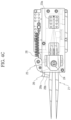
- FIG. 6 A is a cross-sectional view of a master member in an initial condition.
- FIG. 6 B is a diagram showing a wire and a deformable membrane in an initial condition.
- FIG. 7 A is a cross-sectional view of a master member in a pressed condition of a button.
- FIG. 7 B is a diagram showing a wire and a deformable membrane in a pressed condition of a button.
- FIG. 8 A is a cross-sectional view of a master member in an activated condition of a wire by haptic force feedback.
- FIG. 8 B is a diagram showing a wire and a deformable membrane in an activated condition of the wire by haptic force feedback.
- FIG. 9 is a graph showing a reaction force applied to a finger with a change in length of a wire and a deformable membrane.
- FIG. 1 is a perspective view showing a tele-operated forceps-driver variable stiffness master device 100 of the present disclosure
- FIG. 2 A is a perspective view showing a master member 10
- FIG. 2 B is a cross-sectional view showing section B-B′ in FIG. 2 A
- FIG. 2 C is a cross-sectional view showing section C-C′ in FIG. 2 B
- FIG. 2 D is a cross-sectional view showing section D-D′ in FIG. 2 B
- FIG. 3 A is a longitudinal cross-sectional view showing the master member 10 in a non-deformed condition of a deformable membrane 12
- FIG. 3 B is a longitudinal cross-sectional view showing the master member 10 in a deformed condition of the deformable membrane 12 .
- the tele-operated forceps-driver variable stiffness master device 100 of the present disclosure includes the master member 10 and a slave member 20 .
- the master member 10 generates an input displacement signal generated by the pressing with a user's finger.
- the input displacement signal may be generated by a displacement sensor as described below.
- the slave member 20 operates based on the input displacement signal, measures operation information, calculate a gripping force based on the operation information, and provides the master member 10 with a stiffness change command signal or force feedback based on the calculated gripping force.
- the slave member 20 will be described in more detail below.
- the master member 10 may include a button 11 , the deformable membrane 12 and a wire 14 .
- the button 11 may be pressed in one direction when the finger contacts the button 11 .
- the button 11 may include a force sensor 11 a to measure a change in stiffness of the master member 10 .
- FIG. 2 A shown is an example in which the button 11 is formed in a circular shape and installed at the center of the deformable membrane 12 .
- the deformable membrane 12 may be connected to the button 11 , and may extend in a direction perpendicular to said one direction, so the deformable membrane 12 may be deformed by the pressing with the finger.
- FIGS. 2 A, 2 C and 2 D shown is an example in which the deformable membrane is in the shape of a disc as a whole and bent multiple times in the inward direction from the circumference, and by this structure, the deformable membrane 12 can be deformed without damage.
- the deformable membrane 12 may be formed with a multi-plate structure to sufficiently endure stiffness transmitted from the button 11 when pressed with the finger.
- the wire 14 may be deformed in contraction when supplied with power to restore the deformable membrane 12 to the original state.
- the wire 14 may be, for example, an actuator of a shape memory alloy.
- FIGS. 2 C and 2 D shown is an example in which a power supply 14 a that supplies the wire 14 with power is connected to the wire 14 via an electrical wire 14 b .
- the connection relationship of the power supply 14 a connected to the wire 14 with the electrical wire 14 b is not necessarily limited thereto.
- the master member 10 may further include a flange 15 and a wire fixture 17 .
- the flange 15 may be installed outside of the deformable membrane 12 to support the deformable membrane 12 .
- the flange 15 may be formed with a hollow donut shaped structure to support the outer side of the deformable membrane 12 and allow the deformable membrane 12 to be deformed inwards. Referring to FIGS. 2 A and 2 B , shown is an example in which a plurality of flanges 15 is provided and the deformable membrane 12 is interposed between the plurality of flanges 15 .
- the wire fixture 17 may be installed at each of the flange 15 and the deformable membrane 12 to fixedly install the wire 14 .
- the plurality of wire fixtures 17 may be arranged along the circumferential direction of the flanges 15 to allow the deformable membrane 12 to be deformed by tension adjustment of the wire 14 , and may be arranged in a hexagonal shape near the center of the deformable membrane 12 .
- the wire 14 may be installed in the wire fixtures 17 installed at the flanges 15 and the deformable membrane 12 to be placed in tension by the deformation of the deformable membrane 12 , and may deform the deformable membrane 12 when power is applied to the wire 14 .
- the wire 14 may be placed in such a way that the wire 14 is held in two wire fixtures 17 installed at the flanges 15 and subsequently one wire fixture 17 disposed at the center of the deformable membrane 12 , and held again in two wire fixtures 17 installed at the flanges 15 and one wire fixture 17 disposed at the center of the deformable membrane 12 .
- the master member 10 may have a symmetrical shape with respect to a neutral base 16 .
- the master member 10 may further include a displacement sensor 18 and a magnet 19 .
- the displacement sensor 18 may be installed on one surface of the deformable membrane 12 disposed near the neutral base 16 to sense the displacement of the deformable membrane 12 and generate an input displacement signal.
- the neutral base 16 may be formed with a disc shaped structure where the deformable membrane 12 and the flanges 15 are installed.
- the magnet 19 may be spaced apart from the displacement sensor 18 , and installed on one surface of a different deformable membrane 12 with the neutral base interposed between.
- the master member 10 may further include the force sensor 11 a installed in the button 11 to sense a force applied by the contact with the finger.
- FIG. 4 A is a perspective view showing the slave member 20
- FIG. 4 B is an enlarged view of section A of FIG. 4 A
- FIG. 4 C is a plane view of the slave member 20 showing an open condition of a gripper 21 in an initial condition
- FIG. 4 D is a plane view of the slave member 20 showing a closed condition of the gripper 21 .
- the slave member 20 may include the gripper 21 , a body 23 , an opening and closing member 25 , an elastic member 26 and a force sensing module 28 .
- the slave member 20 may be, for example, a forceps driver.
- the gripper 21 is deformed to be open and closed. Additionally, the gripper 21 is installed in the body 23 such that the gripper 21 is received by the body 23 . In the present disclosure, opening and closing of the gripper 21 may be understood as allowing one end of the gripper 21 to grasp or release the tissue or skin.
- the gripper 21 may be formed with a structure in which one end is open and closed.
- the gripper 21 may be forceps or surgical scissors, and FIG. 4 A shows an example in which the gripper 21 is forceps.
- the body 23 is formed to receive the gripper 21 . Additionally, the body 23 may include a gripper holder 23 a to couple the gripper 21 .
- FIG. 4 C and FIG. 4 D shows an example in which the right end of the gripper 21 is coupled to the gripper holder 23 a , and the gripper 21 is installed in the body 23 such that the gripper 21 is received in the body 23 while being open and closed.
- the opening and closing member 25 is rotatably installed in the body 23 to press or release two sides of the gripper 21 .
- FIGS. 4 A and 4 B show an example in which the opening and closing member 25 is rotatably installed in the body 23 such that two ends of the opening and closing member 25 press the gripper 21 .
- the opening and closing member 25 presses the two sides of the gripper 21 in one direction, the end of the gripper 21 may be closed, and in the releasing condition, the opening and closing member 25 may move away from the gripper 21 in one direction, and the gripper 21 may be open.
- the elastic member 26 is connected to one side of the opening and closing member 25 to provide an elastic force to the opening and closing member 25 .
- the elastic member 26 may be, for example, a spring.
- FIGS. 4 C and 4 D show an example in which one end of the elastic member 26 is bolt-connected to the body 23 , and the other end is connected to one side of the opening and closing member 25 .
- a steel wire 27 is connected to the other side of the opening and closing member 25 to allow the opening and closing member 25 to rotate by the driving of a motor 29 .
- the motor 29 may be installed in the body 23 to generate a driving force.
- the motor 29 is supplied with power from the power supply, and provides a rotational force to a motor output member 29 a connected to the motor 29 .
- the steel wire 27 is installed in the motor output member 29 a to provide the driving force to allow the gripper 21 to grasp when pulled by the driving of the motor 29 .
- a rotational displacement sensor 24 may be installed in the body 23 to measure the extent of grasp of the gripper 21 by measuring the amount of rotation of the opening and closing member 25 .
- FIG. 4 A shown is an example in which a cover 23 c is installed on the body 23 and the rotational displacement sensor 24 is installed on the cover 23 c .
- the rotational displacement sensor 24 may be, for example, a positiometer.
- the force sensing module 28 may be installed in the body 23 between the opening and closing member 25 and the gripper 21 .
- the force sensing module 28 may measure a gripping force during the operation of the opening and closing member 25 .
- the force sensing module 28 may include a Printed Circuit Board (PCB), a sensor 28 a and a stress transmitter 28 b.
- PCB Printed Circuit Board
- the PCB supplies the sensor 28 a with power to receive and output information associated with a force measured by the sensor 28 a .
- the stress transmitter 28 b may be made of an elastic material, for example, urethane, to transmit the force when the opening and closing member 25 presses or releases the two sides of the gripper 21 to the sensor 28 a.
- FIG. 5 is a block diagram representing the signal flow of an example of the tele-operated forceps-driver variable stiffness master device 100 including a control unit 30 .
- the tele-operated forceps-driver variable stiffness master device 100 of the present disclosure may further include the control unit 30 .
- the control unit 30 may receive displacement or force information from the master member 10 and control the gripping force of the slave member 20 , and may receive displacement or force information from the slave member 20 and control target stiffness of the master member 10 .
- control unit 30 may receive the displacement information and the force information of the master member 10 from the displacement sensor 18 and the force sensor 11 a of the master member 10 respectively, and provide an operation signal to the motor 29 of the slave member 20 .
- control unit 30 may be electrically connected to each of the displacement sensor 18 and the force sensor 11 a of the master member 10 . Additionally, the control unit 30 may be electrically connected to the motor 29 of the slave member 20 .
- control unit 30 may receive the displacement information and the force information of the slave member 20 from the rotational displacement sensor 24 and the force sensing module 28 of the slave member 20 respectively, and provide an operation signal to the wire 14 of the master member 10 .
- control unit 30 may be electrically connected to each of the rotational displacement sensor 24 and the force sensing module 28 of the slave member 20 . Additionally, the control unit 30 may be electrically connected to the actuator of the master member 10 .
- FIG. 6 A is a cross-sectional view of the master member 10 in the initial condition
- FIG. 6 B is a diagram showing the wire 14 and the deformable membrane 12 in the initial condition
- FIG. 7 A is a cross-sectional view of the master member 10 in the pressed condition of the button 11
- FIG. 7 B is a diagram showing the wire 14 and the deformable membrane 12 in the pressed condition of the button 11
- FIG. 8 A is a cross-sectional view of the master member 10 in an activated condition of the wire 14 by haptic force feedback
- FIG. 8 B is a diagram showing the wire 14 and the deformable membrane 12 in the activated condition of the wire 14 by haptic force feedback
- FIG. 9 is a graph showing a reaction force applied to the finger with a change in length of the wire 14 and the deformable membrane 12 .
- FIG. 6 A shows a cross section of the master member 10 in the initial condition
- FIG. 6 B shows an example of equilibrium between the deformable membrane 12 and the wire 14 in the initial condition. Additionally, since a load is not applied to the master member 10 , the gripper 21 of the slave member 20 is open as shown in FIG. 4 C .
- the deformable membrane 12 is elastically deformed, and in this instance, an elastic deformation displacement is measured by the displacement sensor 18 .
- the control unit 30 provides a command based on the displacement measured by the displacement sensor 18 to operate the slave member 20 .
- the embedded shape memory alloy wire 14 is electrically activated and stiffness of the device is changed, and a change in stiffness of the master member 10 is measured based on the values measured by the force sensor 11 a and the displacement sensor 18 .
- the deformable membrane 12 and the wire 14 are in the deformed condition by the finger pressing the button 11 of the master member 10 , and the wire 14 is activated by haptic force feedback from the slave member 20 .
- the elastic deformation displacement of the deformable membrane 12 generated by pressing the button 11 of the master member 10 with the user's finger is measured by the displacement sensor 18 and the magnet 19 provided in the master member 10 .
- the motor 29 of the slave member 20 is driven based on the displacement value measured by the master member 10 , and a rotational displacement of a rotator by the driving of the motor 29 is measured by the rotational displacement sensor 24 mounted on the slave member 20 .
- a force applied to the gripper 21 while the gripper 21 is closed by the opening and closing member is measured by the force sensing module mounted in the opening and closing member.
- a gripping force applied to the object is calculated based on the value measured by the force sensing module 28 .
- a stiffness change command is applied to the master member 10 based on the calculated gripping force.
- the shape memory alloy of the master member 10 is electrically activated to cause a stiffness change.
- a change in stiffness of the master member 10 is calculated based on the values measured by the displacement sensor 18 and the magnet 19 provided in the master member 10 , and the force sensor 11 a embedded in the button 11 .
- the tele-operated forceps-driver variable stiffness master device of the present disclosure is a system including a slave member to drive a commercially available surgical forceps mounted therein, and a master member to drive the device, and achieves fine force control and gripping force feedback, allowing a wide range of applications in the field of robot-assisted tele-operation microsurgery.
- the tele-operated forceps-driver variable stiffness master device of the present disclosure can be used in tele-operation microsurgery environment augmented reality applications by virtue of a force-blocking function of preventing the application of an excessive force to the flexible microtissue and a haptic feedback scaling function of amplifying a microgripping force and providing to a remote surgeon.
- the tele-operated forceps-driver variable stiffness master device 100 as described hereinabove is not limited to the configuration and method of the embodiments described above, and some or all the embodiments may be selectively combined to make various modification.
Abstract
Description
Claims (7)
Applications Claiming Priority (2)
| Application Number | Priority Date | Filing Date | Title |
|---|---|---|---|
| KR10-2020-0015706 | 2020-02-10 | ||
| KR1020200015706A KR102321778B1 (en) | 2020-02-10 | 2020-02-10 | Tele-operated Forceps-driver Variable Stiffness Master Device |
Publications (2)
| Publication Number | Publication Date |
|---|---|
| US20210244490A1 US20210244490A1 (en) | 2021-08-12 |
| US11786327B2 true US11786327B2 (en) | 2023-10-17 |
Family
ID=77177643
Family Applications (1)
| Application Number | Title | Priority Date | Filing Date |
|---|---|---|---|
| US17/029,286 Active 2042-04-01 US11786327B2 (en) | 2020-02-10 | 2020-09-23 | Tele-operated forceps-driver variable stiffness master device |
Country Status (2)
| Country | Link |
|---|---|
| US (1) | US11786327B2 (en) |
| KR (1) | KR102321778B1 (en) |
Citations (9)
| Publication number | Priority date | Publication date | Assignee | Title |
|---|---|---|---|---|
| JPH07184923A (en) | 1993-12-28 | 1995-07-25 | Hitachi Ltd | Remote precise surgical operation supporting device |
| US6594552B1 (en) | 1999-04-07 | 2003-07-15 | Intuitive Surgical, Inc. | Grip strength with tactile feedback for robotic surgery |
| US20120071863A1 (en) | 2010-09-17 | 2012-03-22 | Samsung Electronics Co., Ltd. | Surgery robot system, surgery apparatus and method for providing tactile feedback |
| KR101830389B1 (en) | 2011-06-10 | 2018-02-21 | 주식회사 미래컴퍼니 | Master gripper of surgical robot and control method of surgical robot having the same |
| KR101948079B1 (en) | 2017-12-04 | 2019-05-20 | 한국과학기술연구원 | Tactile transmission device and User interface system having the same |
| JP2019118546A (en) | 2017-12-28 | 2019-07-22 | 北川工業株式会社 | Grip force measuring device |
| KR20200003653A (en) | 2018-07-02 | 2020-01-10 | 한국과학기술연구원 | Forceps Driver Apparatus |
| JP2020005866A (en) * | 2018-07-06 | 2020-01-16 | 地方独立行政法人神奈川県立産業技術総合研究所 | Medical gripping device |
| US20200289229A1 (en) * | 2019-03-15 | 2020-09-17 | Ethicon Llc | Robotic surgical controls having feedback capabilities |
Family Cites Families (1)
| Publication number | Priority date | Publication date | Assignee | Title |
|---|---|---|---|---|
| KR100925102B1 (en) | 2007-12-10 | 2009-11-05 | 고려대학교 산학협력단 | Remote-controllable surgical robot |
-
2020
- 2020-02-10 KR KR1020200015706A patent/KR102321778B1/en active IP Right Grant
- 2020-09-23 US US17/029,286 patent/US11786327B2/en active Active
Patent Citations (12)
| Publication number | Priority date | Publication date | Assignee | Title |
|---|---|---|---|---|
| JPH07184923A (en) | 1993-12-28 | 1995-07-25 | Hitachi Ltd | Remote precise surgical operation supporting device |
| US6594552B1 (en) | 1999-04-07 | 2003-07-15 | Intuitive Surgical, Inc. | Grip strength with tactile feedback for robotic surgery |
| US20120071863A1 (en) | 2010-09-17 | 2012-03-22 | Samsung Electronics Co., Ltd. | Surgery robot system, surgery apparatus and method for providing tactile feedback |
| KR20120030174A (en) | 2010-09-17 | 2012-03-28 | 삼성전자주식회사 | Surgery robot system and surgery apparatus and method for providing tactile feedback |
| KR101830389B1 (en) | 2011-06-10 | 2018-02-21 | 주식회사 미래컴퍼니 | Master gripper of surgical robot and control method of surgical robot having the same |
| KR101948079B1 (en) | 2017-12-04 | 2019-05-20 | 한국과학기술연구원 | Tactile transmission device and User interface system having the same |
| US20190171290A1 (en) | 2017-12-04 | 2019-06-06 | Korea Institute Of Science And Technology | Tactile transmission device and user interface system including the same |
| JP2019118546A (en) | 2017-12-28 | 2019-07-22 | 北川工業株式会社 | Grip force measuring device |
| EP3705043A1 (en) | 2017-12-28 | 2020-09-09 | Kitagawa Industries Co., Ltd. | Gripping force measurement device |
| KR20200003653A (en) | 2018-07-02 | 2020-01-10 | 한국과학기술연구원 | Forceps Driver Apparatus |
| JP2020005866A (en) * | 2018-07-06 | 2020-01-16 | 地方独立行政法人神奈川県立産業技術総合研究所 | Medical gripping device |
| US20200289229A1 (en) * | 2019-03-15 | 2020-09-17 | Ethicon Llc | Robotic surgical controls having feedback capabilities |
Non-Patent Citations (1)
| Title |
|---|
| Sungwoo Park et al., "A Tele-Operated Microsurgical Forceps-Driver With a Variable Stiffness Haptic Feedback Master Device", IEEE Robotics and Automation Letters, Apr. 2020, pp. 1946-1953, vol. 5, No. 2. |
Also Published As
| Publication number | Publication date |
|---|---|
| KR20210101579A (en) | 2021-08-19 |
| US20210244490A1 (en) | 2021-08-12 |
| KR102321778B1 (en) | 2021-11-05 |
Similar Documents
| Publication | Publication Date | Title |
|---|---|---|
| US10993774B2 (en) | Robotic hand controller | |
| King et al. | A multielement tactile feedback system for robot-assisted minimally invasive surgery | |
| JP4883563B2 (en) | Manipulator device | |
| Wagner et al. | Force feedback benefit depends on experience in multiple degree of freedom robotic surgery task | |
| Culjat et al. | Pneumatic balloon actuators for tactile feedback in robotic surgery | |
| Culjat et al. | A tactile feedback system for robotic surgery | |
| US10532466B2 (en) | Robotic hand controller | |
| US8981914B1 (en) | Portable haptic force magnifier | |
| Dalvand et al. | Modular instrument for a haptically-enabled robotic surgical system (herosurg) | |
| Yoneyama et al. | Force-detecting gripper and force feedback system for neurosurgery applications | |
| Park et al. | A tele-operated microsurgical forceps-driver with a variable stiffness haptic feedback master device | |
| US11786327B2 (en) | Tele-operated forceps-driver variable stiffness master device | |
| Ku et al. | Design and control of a teleoperated microgripper for microsurgery | |
| Culjat et al. | Tactile feedback in surgical robotics | |
| Sarmah et al. | Surgical robot teleoperated laparoscopic grasper with haptics feedback system | |
| US20230233275A1 (en) | Controlling a surgical instrument | |
| Chioson et al. | Implementation of a bilateral teleoperation haptic feedback controls to robotic minimally invasive surgery | |
| US20220104892A1 (en) | Actuation carriage with integrated measurement for robotically controlled surgical instruments | |
| Kong et al. | Indirect measure of joint torques of surgical instrument in robot-assisted laparoscopic surgery | |
| US11911060B2 (en) | Forceps driver apparatus | |
| Grundfest et al. | Development and testing of a tactile feedback system for robotic surgery. | |
| Ku et al. | Dexterity enhancement in microsurgery using a motion-scaling system and microgripper | |
| Wijayarathne et al. | Force Feedback-Enabled Dexterous Robotic Micromanipulation Platform for Surgical Tasks | |
| Schuenemann et al. | Tactile actuators for tactile feedback systems | |
| Lim et al. | Towards hapticsenabled robotic surgery system |
Legal Events
| Date | Code | Title | Description |
|---|---|---|---|
| AS | Assignment |
Owner name: KOREA INSTITUTE OF SCIENCE AND TECHNOLOGY, KOREA, REPUBLIC OF Free format text: ASSIGNMENT OF ASSIGNORS INTEREST;ASSIGNORS:HWANG, DONGHYUN;PARK, SUNGWOO;JANG, NAMSEON;AND OTHERS;SIGNING DATES FROM 20200909 TO 20200918;REEL/FRAME:053856/0606 |
|
| FEPP | Fee payment procedure |
Free format text: ENTITY STATUS SET TO UNDISCOUNTED (ORIGINAL EVENT CODE: BIG.); ENTITY STATUS OF PATENT OWNER: SMALL ENTITY |
|
| FEPP | Fee payment procedure |
Free format text: ENTITY STATUS SET TO SMALL (ORIGINAL EVENT CODE: SMAL); ENTITY STATUS OF PATENT OWNER: SMALL ENTITY |
|
| STPP | Information on status: patent application and granting procedure in general |
Free format text: APPLICATION DISPATCHED FROM PREEXAM, NOT YET DOCKETED |
|
| STPP | Information on status: patent application and granting procedure in general |
Free format text: DOCKETED NEW CASE - READY FOR EXAMINATION |
|
| STPP | Information on status: patent application and granting procedure in general |
Free format text: NON FINAL ACTION MAILED |
|
| STPP | Information on status: patent application and granting procedure in general |
Free format text: RESPONSE TO NON-FINAL OFFICE ACTION ENTERED AND FORWARDED TO EXAMINER |
|
| STPP | Information on status: patent application and granting procedure in general |
Free format text: NOTICE OF ALLOWANCE MAILED -- APPLICATION RECEIVED IN OFFICE OF PUBLICATIONS |
|
| STPP | Information on status: patent application and granting procedure in general |
Free format text: PUBLICATIONS -- ISSUE FEE PAYMENT VERIFIED |
|
| STCF | Information on status: patent grant |
Free format text: PATENTED CASE |