US11707377B2 - Coupling part with a hinge for a medical base plate and sensor assembly part - Google Patents
Coupling part with a hinge for a medical base plate and sensor assembly part Download PDFInfo
- Publication number
- US11707377B2 US11707377B2 US16/954,211 US201816954211A US11707377B2 US 11707377 B2 US11707377 B2 US 11707377B2 US 201816954211 A US201816954211 A US 201816954211A US 11707377 B2 US11707377 B2 US 11707377B2
- Authority
- US
- United States
- Prior art keywords
- base plate
- coupling part
- monitor device
- electrode
- section
- Prior art date
- Legal status (The legal status is an assumption and is not a legal conclusion. Google has not performed a legal analysis and makes no representation as to the accuracy of the status listed.)
- Active, expires
Links
- 230000008878 coupling Effects 0.000 title claims abstract description 677
- 238000010168 coupling process Methods 0.000 title claims abstract description 677
- 238000005859 coupling reaction Methods 0.000 title claims abstract description 677
- 239000010410 layer Substances 0.000 claims description 207
- 239000012790 adhesive layer Substances 0.000 claims description 195
- 230000001070 adhesive effect Effects 0.000 claims description 34
- 239000000853 adhesive Substances 0.000 claims description 32
- 230000000284 resting effect Effects 0.000 claims description 29
- 239000000416 hydrocolloid Substances 0.000 claims description 24
- 230000002829 reductive effect Effects 0.000 claims description 16
- 230000007246 mechanism Effects 0.000 description 55
- 238000003032 molecular docking Methods 0.000 description 42
- 230000000873 masking effect Effects 0.000 description 35
- 239000000203 mixture Substances 0.000 description 31
- 230000002787 reinforcement Effects 0.000 description 22
- -1 tackifiers Substances 0.000 description 10
- 230000003628 erosive effect Effects 0.000 description 9
- 230000003993 interaction Effects 0.000 description 9
- 239000000463 material Substances 0.000 description 9
- 238000012545 processing Methods 0.000 description 9
- XLYOFNOQVPJJNP-UHFFFAOYSA-N water Substances O XLYOFNOQVPJJNP-UHFFFAOYSA-N 0.000 description 9
- 238000003466 welding Methods 0.000 description 9
- 239000004433 Thermoplastic polyurethane Substances 0.000 description 8
- 229920001083 polybutene Polymers 0.000 description 8
- 229920002803 thermoplastic polyurethane Polymers 0.000 description 8
- VSKJLJHPAFKHBX-UHFFFAOYSA-N 2-methylbuta-1,3-diene;styrene Chemical compound CC(=C)C=C.C=CC1=CC=CC=C1.C=CC1=CC=CC=C1 VSKJLJHPAFKHBX-UHFFFAOYSA-N 0.000 description 7
- 229920002367 Polyisobutene Polymers 0.000 description 7
- 238000000034 method Methods 0.000 description 7
- 229920001577 copolymer Polymers 0.000 description 6
- 238000007789 sealing Methods 0.000 description 6
- 229920002725 thermoplastic elastomer Polymers 0.000 description 6
- 230000008901 benefit Effects 0.000 description 5
- 238000004891 communication Methods 0.000 description 5
- 230000000694 effects Effects 0.000 description 5
- OKTJSMMVPCPJKN-UHFFFAOYSA-N Carbon Chemical compound [C] OKTJSMMVPCPJKN-UHFFFAOYSA-N 0.000 description 4
- 239000004642 Polyimide Substances 0.000 description 4
- VYPSYNLAJGMNEJ-UHFFFAOYSA-N Silicium dioxide Chemical compound O=[Si]=O VYPSYNLAJGMNEJ-UHFFFAOYSA-N 0.000 description 4
- PPBRXRYQALVLMV-UHFFFAOYSA-N Styrene Natural products C=CC1=CC=CC=C1 PPBRXRYQALVLMV-UHFFFAOYSA-N 0.000 description 4
- 229920001721 polyimide Polymers 0.000 description 4
- 239000011241 protective layer Substances 0.000 description 4
- 229920006132 styrene block copolymer Polymers 0.000 description 4
- 229920006344 thermoplastic copolyester Polymers 0.000 description 4
- 229920002397 thermoplastic olefin Polymers 0.000 description 4
- 229920006345 thermoplastic polyamide Polymers 0.000 description 4
- 229920006342 thermoplastic vulcanizate Polymers 0.000 description 4
- 230000001133 acceleration Effects 0.000 description 3
- 239000000919 ceramic Substances 0.000 description 3
- 230000008859 change Effects 0.000 description 3
- 230000001419 dependent effect Effects 0.000 description 3
- 238000010030 laminating Methods 0.000 description 3
- 229920000728 polyester Polymers 0.000 description 3
- 230000008569 process Effects 0.000 description 3
- VXNZUUAINFGPBY-UHFFFAOYSA-N 1-Butene Chemical compound CCC=C VXNZUUAINFGPBY-UHFFFAOYSA-N 0.000 description 2
- 229920002134 Carboxymethyl cellulose Polymers 0.000 description 2
- RYGMFSIKBFXOCR-UHFFFAOYSA-N Copper Chemical compound [Cu] RYGMFSIKBFXOCR-UHFFFAOYSA-N 0.000 description 2
- 239000002033 PVDF binder Substances 0.000 description 2
- 239000005062 Polybutadiene Substances 0.000 description 2
- 229920002396 Polyurea Polymers 0.000 description 2
- 239000004820 Pressure-sensitive adhesive Substances 0.000 description 2
- 206010040880 Skin irritation Diseases 0.000 description 2
- 230000001154 acute effect Effects 0.000 description 2
- 239000000654 additive Substances 0.000 description 2
- PNEYBMLMFCGWSK-UHFFFAOYSA-N aluminium oxide Inorganic materials [O-2].[O-2].[O-2].[Al+3].[Al+3] PNEYBMLMFCGWSK-UHFFFAOYSA-N 0.000 description 2
- IAQRGUVFOMOMEM-UHFFFAOYSA-N butene Natural products CC=CC IAQRGUVFOMOMEM-UHFFFAOYSA-N 0.000 description 2
- 238000004140 cleaning Methods 0.000 description 2
- 229910052802 copper Inorganic materials 0.000 description 2
- 239000010949 copper Substances 0.000 description 2
- 238000005520 cutting process Methods 0.000 description 2
- 239000005038 ethylene vinyl acetate Substances 0.000 description 2
- 239000000945 filler Substances 0.000 description 2
- 239000012530 fluid Substances 0.000 description 2
- 230000006870 function Effects 0.000 description 2
- PCHJSUWPFVWCPO-UHFFFAOYSA-N gold Chemical compound [Au] PCHJSUWPFVWCPO-UHFFFAOYSA-N 0.000 description 2
- 229910052737 gold Inorganic materials 0.000 description 2
- 239000010931 gold Substances 0.000 description 2
- 238000010348 incorporation Methods 0.000 description 2
- 238000007373 indentation Methods 0.000 description 2
- 238000002372 labelling Methods 0.000 description 2
- 238000012986 modification Methods 0.000 description 2
- 230000004048 modification Effects 0.000 description 2
- 238000012544 monitoring process Methods 0.000 description 2
- 230000037361 pathway Effects 0.000 description 2
- 239000004014 plasticizer Substances 0.000 description 2
- 229920002587 poly(1,3-butadiene) polymer Polymers 0.000 description 2
- 229920002857 polybutadiene Polymers 0.000 description 2
- 229920001195 polyisoprene Polymers 0.000 description 2
- 229920001296 polysiloxane Polymers 0.000 description 2
- 229920000346 polystyrene-polyisoprene block-polystyrene Polymers 0.000 description 2
- 239000004810 polytetrafluoroethylene Substances 0.000 description 2
- 229920001343 polytetrafluoroethylene Polymers 0.000 description 2
- 229920002635 polyurethane Polymers 0.000 description 2
- 239000004814 polyurethane Substances 0.000 description 2
- 229920002981 polyvinylidene fluoride Polymers 0.000 description 2
- 238000007639 printing Methods 0.000 description 2
- 230000000717 retained effect Effects 0.000 description 2
- 238000007790 scraping Methods 0.000 description 2
- 239000000377 silicon dioxide Substances 0.000 description 2
- 230000036556 skin irritation Effects 0.000 description 2
- 231100000475 skin irritation Toxicity 0.000 description 2
- 230000005236 sound signal Effects 0.000 description 2
- 229920000468 styrene butadiene styrene block copolymer Polymers 0.000 description 2
- 229920001609 Poly(3,4-ethylenedioxythiophene) Polymers 0.000 description 1
- BQCADISMDOOEFD-UHFFFAOYSA-N Silver Chemical compound [Ag] BQCADISMDOOEFD-UHFFFAOYSA-N 0.000 description 1
- RTAQQCXQSZGOHL-UHFFFAOYSA-N Titanium Chemical compound [Ti] RTAQQCXQSZGOHL-UHFFFAOYSA-N 0.000 description 1
- 230000003187 abdominal effect Effects 0.000 description 1
- 239000004411 aluminium Substances 0.000 description 1
- XAGFODPZIPBFFR-UHFFFAOYSA-N aluminium Chemical compound [Al] XAGFODPZIPBFFR-UHFFFAOYSA-N 0.000 description 1
- 229910052782 aluminium Inorganic materials 0.000 description 1
- 230000004888 barrier function Effects 0.000 description 1
- 238000005452 bending Methods 0.000 description 1
- 230000015572 biosynthetic process Effects 0.000 description 1
- 229910052799 carbon Inorganic materials 0.000 description 1
- 239000006229 carbon black Substances 0.000 description 1
- 229910021393 carbon nanotube Inorganic materials 0.000 description 1
- 239000002041 carbon nanotube Substances 0.000 description 1
- 239000004020 conductor Substances 0.000 description 1
- 238000001514 detection method Methods 0.000 description 1
- 238000010586 diagram Methods 0.000 description 1
- 239000000835 fiber Substances 0.000 description 1
- 229910021389 graphene Inorganic materials 0.000 description 1
- 229910002804 graphite Inorganic materials 0.000 description 1
- 239000010439 graphite Substances 0.000 description 1
- 230000036541 health Effects 0.000 description 1
- 238000007455 ileostomy Methods 0.000 description 1
- 238000003780 insertion Methods 0.000 description 1
- 230000037431 insertion Effects 0.000 description 1
- 239000011810 insulating material Substances 0.000 description 1
- 210000000936 intestine Anatomy 0.000 description 1
- 238000003698 laser cutting Methods 0.000 description 1
- 238000010147 laser engraving Methods 0.000 description 1
- 239000010808 liquid waste Substances 0.000 description 1
- 238000004519 manufacturing process Methods 0.000 description 1
- 230000000149 penetrating effect Effects 0.000 description 1
- 229920003023 plastic Polymers 0.000 description 1
- 239000004033 plastic Substances 0.000 description 1
- 229920000767 polyaniline Polymers 0.000 description 1
- 229920000128 polypyrrole Polymers 0.000 description 1
- 238000002360 preparation method Methods 0.000 description 1
- 238000004080 punching Methods 0.000 description 1
- 239000004332 silver Substances 0.000 description 1
- 229910052709 silver Inorganic materials 0.000 description 1
- 230000037380 skin damage Effects 0.000 description 1
- 239000002910 solid waste Substances 0.000 description 1
- 229910001220 stainless steel Inorganic materials 0.000 description 1
- 239000010935 stainless steel Substances 0.000 description 1
- 238000003860 storage Methods 0.000 description 1
- 238000001356 surgical procedure Methods 0.000 description 1
- 210000004243 sweat Anatomy 0.000 description 1
- 230000002123 temporal effect Effects 0.000 description 1
- 239000010936 titanium Substances 0.000 description 1
- 229910052719 titanium Inorganic materials 0.000 description 1
- 238000012546 transfer Methods 0.000 description 1
- 210000001635 urinary tract Anatomy 0.000 description 1
- 230000000007 visual effect Effects 0.000 description 1
- 239000002699 waste material Substances 0.000 description 1
Images


Classifications
-
- A—HUMAN NECESSITIES
- A61—MEDICAL OR VETERINARY SCIENCE; HYGIENE
- A61F—FILTERS IMPLANTABLE INTO BLOOD VESSELS; PROSTHESES; DEVICES PROVIDING PATENCY TO, OR PREVENTING COLLAPSING OF, TUBULAR STRUCTURES OF THE BODY, e.g. STENTS; ORTHOPAEDIC, NURSING OR CONTRACEPTIVE DEVICES; FOMENTATION; TREATMENT OR PROTECTION OF EYES OR EARS; BANDAGES, DRESSINGS OR ABSORBENT PADS; FIRST-AID KITS
- A61F5/00—Orthopaedic methods or devices for non-surgical treatment of bones or joints; Nursing devices; Anti-rape devices
- A61F5/44—Devices worn by the patient for reception of urine, faeces, catamenial or other discharge; Portable urination aids; Colostomy devices
- A61F5/443—Devices worn by the patient for reception of urine, faeces, catamenial or other discharge; Portable urination aids; Colostomy devices having adhesive seals for securing to the body, e.g. of hydrocolloid type, e.g. gels, starches, karaya gums
-
- A—HUMAN NECESSITIES
- A61—MEDICAL OR VETERINARY SCIENCE; HYGIENE
- A61F—FILTERS IMPLANTABLE INTO BLOOD VESSELS; PROSTHESES; DEVICES PROVIDING PATENCY TO, OR PREVENTING COLLAPSING OF, TUBULAR STRUCTURES OF THE BODY, e.g. STENTS; ORTHOPAEDIC, NURSING OR CONTRACEPTIVE DEVICES; FOMENTATION; TREATMENT OR PROTECTION OF EYES OR EARS; BANDAGES, DRESSINGS OR ABSORBENT PADS; FIRST-AID KITS
- A61F5/00—Orthopaedic methods or devices for non-surgical treatment of bones or joints; Nursing devices; Anti-rape devices
- A61F5/44—Devices worn by the patient for reception of urine, faeces, catamenial or other discharge; Portable urination aids; Colostomy devices
- A61F5/445—Colostomy, ileostomy or urethrostomy devices
- A61F2005/4486—Colostomy, ileostomy or urethrostomy devices with operable locking ring
-
- A—HUMAN NECESSITIES
- A61—MEDICAL OR VETERINARY SCIENCE; HYGIENE
- A61F—FILTERS IMPLANTABLE INTO BLOOD VESSELS; PROSTHESES; DEVICES PROVIDING PATENCY TO, OR PREVENTING COLLAPSING OF, TUBULAR STRUCTURES OF THE BODY, e.g. STENTS; ORTHOPAEDIC, NURSING OR CONTRACEPTIVE DEVICES; FOMENTATION; TREATMENT OR PROTECTION OF EYES OR EARS; BANDAGES, DRESSINGS OR ABSORBENT PADS; FIRST-AID KITS
- A61F5/00—Orthopaedic methods or devices for non-surgical treatment of bones or joints; Nursing devices; Anti-rape devices
- A61F5/44—Devices worn by the patient for reception of urine, faeces, catamenial or other discharge; Portable urination aids; Colostomy devices
- A61F5/445—Colostomy, ileostomy or urethrostomy devices
- A61F5/448—Means for attaching bag to seal ring
Definitions
- the present disclosure relates to an ostomy system, devices thereof, method of manufacturing and method for monitoring an ostomy appliance.
- the ostomy appliance system comprises an ostomy appliance and an ostomy monitor device.
- the present disclosure relates to leakage classification and/or detection and monitoring of the operation of an ostomy appliance.
- FIG. 1 illustrates an exemplary ostomy system
- FIG. 2 illustrates an exemplary monitor device of the ostomy system
- FIG. 3 is an exploded view of a base plate of an ostomy appliance
- FIG. 4 is an exploded view of an exemplary electrode assembly
- FIG. 5 is a proximal view of parts of a base plate and/or sensor assembly part
- FIG. 6 is a distal view of an exemplary electrode configuration
- FIG. 7 is a distal view of an exemplary masking element
- FIG. 8 is a distal view of an exemplary first adhesive layer
- FIG. 9 is a proximal view of the first adhesive layer of FIG. 8 .
- FIG. 10 is a distal view of a part of the base plate and/or sensor assembly part including a monitor interface
- FIG. 11 a illustrates an exploded view of an exemplary base plate
- FIG. 11 b illustrates an exploded view of an exemplary base plate
- FIG. 12 illustrates an exploded view of an exemplary electrode assembly
- FIG. 13 illustrates an exploded view of an exemplary electrode assembly
- FIG. 14 shows an exemplary electrode configuration
- FIG. 15 shows a schematic representation of part of a base plate and/or a sensor assembly part
- FIG. 16 shows a schematic representation of part of a base plate and/or a sensor assembly par
- FIG. 17 shows a schematic representation of part of a base plate and/or a sensor assembly par
- FIG. 18 shows a schematic representation of part of a base plate and/or a sensor assembly par
- FIG. 19 shows a schematic representation of part of a base plate and/or a sensor assembly par
- FIG. 20 shows a schematic representation of part of a base plate and/or a sensor assembly par
- FIG. 21 shows a schematic representation of part of a base plate and/or a sensor assembly par
- FIG. 22 schematically illustrates an exemplary base plate and monitor device
- FIG. 23 schematically illustrates part of an exemplary base plate and monitor device
- FIG. 24 schematically illustrates an exemplary monitor device
- FIG. 25 schematically illustrates an exemplary base plate and monitor device
- FIG. 26 schematically illustrates part of an exemplary base plate and monitor device
- FIG. 27 schematically illustrates an exemplary base plate
- FIG. 28 schematically illustrates an exemplary base plate and monitor device
- FIG. 29 schematically illustrates an exemplary coupling part
- FIG. 30 schematically illustrates an exemplary coupling part
- FIG. 31 schematically illustrates an exemplary coupling part
- FIG. 32 schematically illustrates an exemplary coupling part
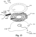
- FIG. 33 schematically illustrates an exploded view of an exemplary base plate
- FIG. 34 schematically illustrates an exemplary coupling part and part of an electrode assembly.
- stoma and ostomy are used to denote a surgically created opening bypassing the intestines or urinary tract system of a person.
- the words are used interchangeably, and no differentiated meaning is intended. The same applies for any words or phrases derived from these, e.g. “stomal”, “ostomies” etc.
- solid and liquid wastes emanating from the stoma may be referred to as both stomal “output,” “waste(s),” and “fluids” interchangeably.
- a subject having undergone ostomy surgery may be referred to as “ostomist” or “ostomate”—moreover, also as “patient” or “user”.
- HCP health care professional
- proximal side or surface of a layer an element, a device or part of a device
- the referral is to the skin-facing side or surface, when a user wears the ostomy appliance.
- distal side or surface of a layer an element, a device or part of a device
- the referral is to the side or surface facing away from the skin, when a user wears the ostomy appliance.
- the proximal side or surface is the side or surface closest to the user, when the appliance is fitted on a user and the distal side is the opposite side or surface—the side or surface furthest away from the user in use.
- the axial direction is defined as the direction of the stoma, when a user wears the appliance.
- the axial direction is generally perpendicular to the skin or abdominal surface of the user.
- the radial direction is defined as perpendicular to the axial direction.
- the words “inner” and “outer” may be used. These qualifiers should generally be perceived with respect to the radial direction, such that a reference to an “outer” element means that the element is farther away from a centre portion of the ostomy appliance than an element referenced as “inner”.
- “innermost” should be interpreted as the portion of a component forming a centre of the component and/or being adjacent to the centre of the component.
- “outermost” should be interpreted as a portion of a component forming an outer edge or outer contour of a component and/or being adjacent to that outer edge or outer contour.
- the present disclosure provides an ostomy system and devices thereof, such as an ostomy appliance, a base plate for an ostomy appliance, a monitor device, and optionally one or more accessory devices which either alone or together facilitate reliable determination of the nature, severity and rapidness of moisture propagation in the adhesive material provided for attaching the base plate to the skin surface of a user.
- the ostomy system and devices thereof enable providing information to the user about the type of failure, and in turn enable providing an indication to the user of the severity and thus the remaining time frame for replacing the ostomy appliance without experiencing severe leakage and/or skin damage.
- the ostomy appliance comprises a base plate and an ostomy pouch (also referred to as an ostomy bag).
- the ostomy appliance may be a colostomy appliance, an ileostomy appliance or a urostomy appliance.
- the ostomy appliance may be a two-part ostomy appliance, i.e. the base plate and the ostomy pouch may be releasably coupled e.g. with a mechanical and/or an adhesive coupling, e.g. to allow that a plurality of ostomy pouches can be utilized (exchanged) with one base plate. Further, a two-part ostomy appliance may facilitate correct application of the base plate to skin, e.g.
- the ostomy appliance may be a one-part ostomy appliance, i.e. the base plate and the ostomy pouch may be fixedly attached to each other.
- the base plate is configured for coupling to a user's stoma and/or skin surrounding the stoma, such as a peristomal skin area.
- the ostomy appliance includes a base plate, such as a monolithic, one-piece base plate, e.g. integrated with a sensor assembly part, or a base plate and a separate sensor assembly part, such as a sensor assembly part to be subsequently applied to a base plate.
- a base plate such as a monolithic, one-piece base plate, e.g. integrated with a sensor assembly part, or a base plate and a separate sensor assembly part, such as a sensor assembly part to be subsequently applied to a base plate.
- a base plate such as a monolithic, one-piece base plate, e.g. integrated with a sensor assembly part, or a base plate and a separate sensor assembly part, such as a sensor assembly part to be subsequently applied to a base plate.
- a separate sensor assembly part such as a sensor assembly part to be subsequently applied to a base plate.
- a sensor assembly part may be adapted to adhere to an ostomy plate.
- a disclosed method of attaching a base plate to a user's stoma and/or skin surrounding the stoma, such as the peristomal skin area may comprise attaching a sensor assembly part to a base plate and attaching the base plate, e.g. together with the attached sensor assembly part, to the user's stoma and/or skin surrounding the stoma, such as the peristomal skin area.
- the method of attaching the base plate to the user's stoma and/or skin surrounding the stoma may comprise attaching the sensor assembly part to the user's stoma and/or skin surrounding the stoma and attaching the base plate to the user's stoma and/or skin surrounding the stoma above the attached sensor assembly part.
- the base plate and/or the sensor assembly part may comprise a first adhesive layer, also denoted center adhesive layer.
- the first adhesive layer adheres to the user's skin (peristomal area) and/or to additional seals, such as sealing paste, sealing tape and/or sealing ring.
- the first adhesive layer may be configured for attachment of the base plate and/or the sensor assembly part to the skin surface of a user.
- the first adhesive layer may have a stomal opening, such as a first adhesive stomal opening, with a center point.
- the first composition may be a pressure sensitive adhesive composition suitable for medical purposes comprising a rubbery elastomeric base and one or more water soluble or water swellable hydrocolloids.
- the first composition may comprise one or more polybutenes, one or more styrene copolymers, one or more hydrocolloids, or any combination thereof.
- the combination of the adhesive properties of the polybutenes and the absorbing properties of the hydrocolloids renders the first composition suitable for use in ostomy appliances.
- the styrene copolymer may for example be a styrene-butadiene-styrene block copolymer or a styrene-isoprene-styrene block copolymer.
- styrene-isoprene-styrene (SIS) block type copolymers are employed.
- the amount of styrene block-copolymer may be from 5% to 20% of the total adhesive composition.
- the butene component is suitably a conjugated butadiene polymer selected from polybutadiene, polyisoprene.
- the polybutenes are preferably present in an amount of from 35-50% of the total adhesive composition.
- the polybutene is polyisobutylene (PIB).
- Suitable hydrocolloids for incorporation in the first composition are selected from naturally occurring hydrocolloids, semisynthetic hydrocolloids and synthetic hydrocolloids.
- the first composition may comprise 20-60% hydrocolloids.
- a preferred hydrocolloid is carboxymethylcellulose (CMC).
- the first composition may optionally contain other components, such as fillers, tackifiers, plasticizers, and other additives.
- the first adhesive layer may have a plurality of sensor point openings.
- a sensor point opening of the first adhesive layer is optionally configured to overlap a part of an electrode, e.g. to form a sensor point.
- the sensor point openings of the first adhesive layer may comprise secondary sensor point openings.
- the secondary sensor point openings may comprise one or more secondary first sensor point openings and one or more secondary second sensor point openings, the secondary first sensor point openings configured to overlap parts of an electrode and the secondary second sensor point openings configured to overlap parts of another electrode different from the electrode at least partly overlapped by the secondary first sensor point openings.
- the sensor point openings of the first adhesive layer may comprise tertiary sensor point openings.
- the tertiary sensor point openings may comprise one or more tertiary first sensor point openings and one or more tertiary second sensor point openings, the tertiary first sensor point openings configured to overlap parts of an electrode and the tertiary second sensor point openings configured to overlap parts of another electrode different from the electrode at least partly overlapped by the tertiary first sensor point openings.
- the first adhesive layer may have a substantially uniform thickness.
- the first adhesive layer may have a thickness in the range from 0.1 mm to 1.5 mm, e.g. in the range from 0.2 mm to 1.2 mm.
- the first adhesive layer may have a primary thickness in a primary part of the first adhesive layer, e.g. in a primary region within a primary radial distance or in a primary radial distance range from the center point of the stomal opening.
- the primary thickness may be in the range from 0.2 mm to 1.5 mm. such as about 1.0 mm.
- the primary radial distance may be in the range from 20 mm to 50 mm, such as in the range from 25 mm to 35 mm, e.g. 30 mm.
- the first adhesive layer may have a secondary thickness in a secondary part of the first adhesive layer, e.g. in a secondary region outside a secondary radial distance or in a secondary radial distance range from the center point of the stomal opening.
- the secondary thickness may be in the range from 0.2 mm to 1.0 mm, such as about 0.5 mm.
- the base plate and/or the sensor assembly part may comprise a second layer.
- the second layer may be a second adhesive layer, also denoted rim adhesive layer.
- the second layer may have a second radial extension that is larger than a first radial extension of the first adhesive layer at least in a first angular range of the base plate and/or the sensor assembly part.
- a part of a proximal surface of the second layer may be configured for attachment to the skin surface of a user.
- the part of a proximal surface of the second layer configured for attachment to the skin surface of a user is also denoted the skin attachment surface of the second adhesive layer.
- the second layer may have a stomal opening, such as a second layer stomal opening and/or a second adhesive stomal opening, with a center point.
- the second adhesive layer may be made of a second composition.
- the second composition may comprise one or more polyisobutenes and/or styrene-isoprene-styrene.
- the second composition may comprise one or more hydrocolloids.
- the second composition may comprise one or more water soluble or water swellable hydrocolloids.
- the second composition may be a pressure sensitive adhesive composition suitable for medical purposes comprising a rubbery elastomeric base and one or more water soluble or water swellable hydrocolloids.
- the second composition may comprise one or more polybutenes, one or more styrene copolymers, one or more hydrocolloids, or any combination thereof.
- the combination of the adhesive properties of the polybutenes and the absorbing properties of the hydrocolloids renders the second composition suitable for use in ostomy appliances.
- the styrene copolymer may for example be a styrene-butadiene-styrene block copolymer or a styrene-isoprene-styrene block copolymer.
- styrene-isoprene-styrene (SIS) block type copolymers are employed.
- the amount of styrene block-copolymer may be from 5% to 20% of the total adhesive composition.
- the butene component is suitably a conjugated butadiene polymer selected from polybutadiene, polyisoprene.
- the polybutenes are preferably present in an amount of from 35-50% of the total adhesive composition.
- the polybutene is polyisobutylene (PIB).
- Suitable hydrocolloids for incorporation in the second composition are selected from naturally occurring hydrocolloids, semisynthetic hydrocolloids and synthetic hydrocolloids.
- the second composition may comprise 20-60% hydrocolloids.
- a preferred hydrocolloid is carboxymethylcellulose (CMC).
- the second composition may optionally contain other components, such as fillers, tackifiers, plasticizers, and other additives.
- the second adhesive layer and the first adhesive layer may have different properties.
- the second adhesive layer (second composition) and the first adhesive layer (first composition) may have different ratios of polyisobutenes, styrene-isoprene-styrene, and/or hydrocolloids.
- the second adhesive layer may provide a stronger attachment to the skin compared to attachment to the skin provided by the first adhesive layer.
- the second adhesive layer may be thinner than the first adhesive layer.
- the second adhesive layer may be less water and/or sweat absorbing than the first adhesive layer.
- the second adhesive layer may be less mouldable than the first adhesive layer.
- the second adhesive layer may provide a second barrier against leakage.
- the second layer may have a substantially uniform thickness.
- the second layer may have a thickness in the range from 0.1 mm to 1.5 mm, e.g. in the range from 0.2 mm to 1.0 mm, such as 0.5 mm, 0.6 mm, or 0.7 mm.
- the base plate and/or the sensor assembly part may comprise one or more electrodes, such as a plurality of electrodes, such as two, three, four, five, six, seven or more electrodes.
- the sensor assembly part may be applied to the base plate, such as to provide the base plate with the one or more electrodes.
- the electrodes may be arranged between the first adhesive layer and the second adhesive layer.
- the electrodes may be arranged in an electrode assembly, e.g. an electrode layer.
- An electrode comprises a connection part for connecting the electrodes to other components and/or interface terminals.
- An electrode may comprise one or more conductor parts and/or one or more sensing parts.
- the electrode assembly may be arranged between the first adhesive layer and the second adhesive layer.
- the base plate and/or the sensor assembly part e.g. the electrode assembly, may comprise a first electrode, a second electrode and optionally a third electrode.
- the base plate and/or the sensor assembly part e.g. the electrode assembly, may comprise a fourth electrode and/or a fifth electrode.
- the base plate and/or the sensor assembly part e.g. the electrode assembly, optionally comprises a sixth electrode.
- the base plate and/or the sensor assembly part, e.g. the electrode assembly may comprise a ground electrode.
- the ground electrode may comprise a first electrode part.
- the first electrode part of the ground electrode may form a ground for the first electrode.
- the ground electrode may comprise a second electrode part.
- the second electrode part of the ground electrode may form a ground for the second electrode.
- the ground electrode may comprise a third electrode part.
- the third electrode part of the ground electrode may form a ground for the third electrode.
- the ground electrode may comprise a fourth electrode part.
- the fourth electrode part of the ground electrode may form a ground for the fourth electrode and/or the fifth electrode.
- the ground electrode or electrode parts of the ground electrode may be configured as or form a (common) reference electrode for some or all of the other electrodes of the electrode assembly.
- the ground electrode may also be denoted reference electrode.
- the electrodes are electrically conductive and may comprise one or more of metallic (e.g. silver, copper, gold, titanium, aluminium, stainless steel), ceramic (e.g. ITO), polymeric (e.g. PEDOT, PANI, PPy), and carbonaceous (e.g. carbon black, carbon nanotube, carbon fibre, graphene, graphite) materials.
- metallic e.g. silver, copper, gold, titanium, aluminium, stainless steel
- ceramic e.g. ITO
- polymeric e.g. PEDOT, PANI, PPy
- carbonaceous e.g. carbon black, carbon nanotube, carbon fibre, graphene, graphite
- Two electrodes of the electrode assembly may form a sensor.
- the first electrode and the ground electrode (e.g. first electrode part of the ground electrode) may form a first sensor or first electrode pair.
- the second electrode and the ground electrode (e.g. second electrode part of the ground electrode) may form a second sensor or second electrode pair.
- the third electrode and the ground electrode (e.g. third electrode part of the ground electrode) may form a third sensor or third electrode pair.
- the fourth electrode and the ground electrode e.g. fourth electrode part of the ground electrode
- the fifth electrode and the ground electrode (e.g. fifth electrode part of the ground electrode) may form a fifth sensor or fifth electrode pair.
- the first electrode may form an open loop.
- the second electrode may form an open loop and/or the third electrode may form an open loop.
- the fourth electrode may form an open loop.
- the fifth electrode may form an open loop. Open loop electrode(s) enables electrode arrangement in few or a single electrode layer.
- the support layer may comprise polymeric (e.g. polyurethane, PTFE, PVDF) and/or ceramic (e.g. alumina, silica) materials.
- the support layer is made of thermoplastic polyurethane (TPU).
- the support layer material may be made of or comprise one or more of polyester, a thermoplastic elastomer (TPE), polyimide, polyimide, Ethylene-vinyl acetate (EVA), polyurea, and silicones.
- thermoplastic elastomers of the support layer are styrenic block copolymers (TPS, TPE-s), thermoplastic polyolefinelastomers (TPO, TPE-o), thermoplastic Vulcanizates (TPV, TPE-v), thermoplastic polyurethanes (TPU), thermoplastic copolyester (TPC, TPE-E), and thermoplastic polyamides (TPA, TPE-A).
- TPS styrenic block copolymers
- TPO thermoplastic polyolefinelastomers
- TPV thermoplastic Vulcanizates
- TPU thermoplastic polyurethanes
- TPC thermoplastic copolyester
- TPE-A thermoplastic polyamides
- the base plate and/or the sensor assembly part, such as the electrode assembly may comprise a masking element configured to insulate at least parts of the electrodes from the first adhesive layer of the base plate and/or the sensor assembly part.
- the masking element may comprise one or more, such as a plurality of, sensor point openings.
- the sensor point openings may comprise primary sensor point openings and/or secondary sensor point openings.
- the sensor point openings may comprise tertiary sensor point opening(s).
- the sensor point openings may comprise quaternary sensor point opening(s)
- a sensor point opening of the masking element overlaps at least one electrode of the electrode assembly when seen in the axial direction, e.g. to form a sensor point.
- a primary sensor point opening may overlap a part of the ground electrode and/or a part of the fourth electrode.
- a secondary sensor point opening may overlap a part of the fourth electrode and/or a part of the fifth electrode.
- a tertiary sensor point opening may overlap a part of the fifth electrode and/or a part of the ground electrode.
- the masking element may comprise one or more, such as a plurality of, terminal openings.
- the masking element may comprise polymeric (e.g. polyurethane, PTFE, PVDF) and/or ceramic (e.g. alumina, silica) materials.
- the masking element is made of or comprises thermoplastic polyurethane (TPU).
- the masking element is made of or comprises polyester.
- the masking element material may be made of or comprise one or more of polyester, a thermoplastic elastomer (TPE), polyimide, polyimide, Ethylene-vinyl acetate (EVA), polyurea, and silicones.
- thermoplastic elastomers of the masking element are styrenic block copolymers (TPS, TPE-s), thermoplastic polyolefinelastomers (TPO, TPE-o), thermoplastic Vulcanizates (TPV, TPE-v), thermoplastic polyurethanes (TPU), thermoplastic copolyester (TPC, TPE-E), and thermoplastic polyamides (TPA, TPE-A).
- the base plate and/or the sensor assembly part may comprise a first intermediate element.
- the first intermediate element may be arranged between the electrodes/electrode layer and the first adhesive layer and/or between the second layer and the first adhesive layer.
- the first intermediate layer may be made of an insulating material.
- the base plate and/or the sensor assembly part may comprise a release liner.
- the release liner is a protective layer that protects adhesive layer(s) during transport and storage and is peeled off by the user prior to applying the base plate and/or the sensor assembly part on the skin.
- the release liner may have a stomal opening, such as a release liner stomal opening, with a center point.
- the base plate and/or the sensor assembly part may comprise a top layer.
- the top layer is a protective layer protecting the adhesive layer(s) from external strains and stress when the user wears the ostomy appliance.
- the electrodes e.g. some or all the electrodes, may be arranged between the first adhesive layer and the top layer.
- the top layer may have a stomal opening, such as a top layer stomal opening, with a center point.
- the top layer may have a thickness in the range from 0.01 mm to 1.0 mm, e.g. in the range from 0.02 mm to 0.2 mm, such as 0.04 mm.
- the base plate and/or the sensor assembly part comprises a monitor interface.
- the monitor interface may be configured for electrically and/or mechanically connecting the ostomy appliance (base plate/sensor assembly part) to the monitor device.
- the monitor interface may be configured for wirelessly connecting the ostomy appliance (base plate/sensor assembly part) to the monitor device.
- the monitor interface of the base plate and/or the sensor assembly part is configured to electrically and/or mechanically couple the ostomy appliance and the monitor device.
- the monitor interface of the base plate and/or the sensor assembly part may comprise, e.g. as part of a first connector of the monitor interface, a coupling part for forming a mechanical connection, such as a releasable coupling between the monitor device and the base plate and/or the sensor assembly part.
- the coupling part may be configured to engage with a coupling part of the monitor device for releasably coupling the monitor device to the base plate and/or the sensor assembly part.
- the monitor interface of the base plate and/or the sensor assembly part may comprise, e.g. as part of a first connector of the monitor interface, a plurality of terminals, such as two, three, four, five, six, seven or more terminals, for forming electrical connections with respective terminals of the monitor device.
- the monitor interface may comprise a ground terminal element forming a ground terminal.
- the monitor interface may comprise a first terminal element forming a first terminal, a second terminal element forming a second terminal and optionally a third terminal element forming a third terminal.
- the monitor interface may comprise a fourth terminal element forming a fourth terminal and/or a fifth terminal element forming a fifth terminal.
- the monitor interface optionally comprises a sixth terminal element forming a sixth terminal.
- the terminal elements of the monitor interface may contact respective electrodes of the base plate and/or the sensor assembly part, such as the electrode assembly.
- the first intermediate element may be arranged between the terminal elements and the first adhesive layer.
- the first intermediate element may cover or overlap terminal element(s) of the base plate and/or the sensor assembly part when seen in the axial direction.
- the first adhesive layer may be protected or experience more evenly distributed mechanical stress from the terminal elements of the base plate and/or the sensor assembly part, in turn reducing the risk of terminal elements penetrating or otherwise damaging the first adhesive layer.
- the first intermediate element may protect or mechanically and/or electrically shield the first adhesive layer from the terminal elements of the base plate and/or the sensor assembly part.
- a terminal element such as the ground terminal element, the first terminal element, the second terminal element, the third terminal element, the fourth terminal element, the fifth terminal element and/or the sixth terminal element, may comprise a distal end and a proximal end.
- a terminal element such as the ground terminal element, the first terminal element, the second terminal element, the third terminal element, the fourth terminal element, the fifth terminal element and/or the sixth terminal element, may comprise a distal part, a centre part, and/or a proximal part. The distal part may be between the distal end and the centre part. The proximal part may be between the proximal end and the centre part.
- a terminal element, such as the ground terminal element, the first terminal element, the second terminal element, the third terminal element, the fourth terminal element, the fifth terminal element and/or the sixth terminal element may be gold plated copper.
- the base plate may comprise a coupling ring or other coupling member for coupling an ostomy pouch to the base plate (two-part ostomy appliance).
- the center point may be defined as a center of the coupling ring.
- the base plate and/or the sensor assembly part may have a stomal opening, e.g. with a center point.
- the stomal opening of the base plate and/or the sensor assembly part may be formed collectively of stomal opening(s) of the layers of the base plate and/or the sensor assembly part, such as of the top layer, the first adhesive layer, the second layer and/or the sensor assembly part.
- the stomal opening(s) of the layers of the base plate and/or the sensor assembly part, such as of the top layer, the first adhesive layer, the second layer and/or the sensor assembly part may be aligned to form the stomal opening of the base plate and/or the sensor assembly part.
- the stomal opening may be a through-going passage of the base plate and/or the sensor assembly part.
- the stomal opening may be arranged substantially in the center of the base plate and/or the sensor assembly part.
- the stomal opening(s) of the layers of the base plate and/or the sensor assembly part may be arranged substantially in the center of the respective layer.
- the stomal opening may be configured to receive a stoma of the user and/or the stomal opening may be configured to allow output from the stoma to pass through the stomal opening an into an ostomy pouch attached to the base plate.
- the stomal opening may be configured to allow passage of output from a proximal side of the base plate and/or sensor assembly part to a distal side of the base plate and/or sensor assembly part.
- the size and/or shape of the stomal opening is typically adjusted by the user or nurse before application of the ostomy appliance to accommodate the user's stoma.
- the user forms the stomal opening during preparation of the base plate and/or the sensor assembly part for application.
- the monitor device comprises a processor and one or more interfaces, such as a first interface and/or a second interface.
- the monitor device may comprise a memory for storing ostomy data.
- the processor is configured to apply a processing scheme
- the first interface is connected to the processor and the memory
- the first interface is configured for collecting ostomy data from the base plate and/or the sensor assembly part coupled to the first interface.
- the ostomy data may comprise one or more, such as all, of first ostomy data from a first electrode pair of the base plate and/or the sensor assembly part, second ostomy data from a second electrode pair of the base plate and/or the sensor assembly part, and third ostomy data from a third electrode pair of the base plate and/or the sensor assembly part.
- a second interface is connected to the processor.
- To apply a processing scheme may comprise one or more of obtain first parameter data based on the first ostomy data; obtain second parameter data based on the second ostomy data; and obtain third parameter data based on the third ostomy data.
- To apply a processing scheme may comprise determine an operating state of the base plate of the ostomy appliance based on one or more, such as all, of the first parameter data, the second parameter data and the third parameter data. The operating state may be indicative of a degree of radial erosion of the base plate and/or the sensor assembly part, such as of the first adhesive layer, and/or an acute leakage risk for the ostomy appliance.
- the monitor device is configured to, in accordance with a determination that the operating state is a first operating state, transmit a first monitor signal comprising monitor data indicative of the first operating state of the base plate via the second interface; and/or in accordance with a determination that the operating state is a second operating state, transmit a second monitor signal comprising monitor data indicative of the second operating state of the base plate via the second interface.
- the first operating state of the base plate corresponds to a situation wherein the first adhesive layer of the base plate and/or the sensor assembly part has experienced a first degree of radial erosion, e.g. the first adhesive layer is eroded to a first radial distance of the first electrode pair but not to a second radial distance of the second electrode pair.
- the second operating state of the base plate corresponds to a situation wherein the first adhesive layer of the base plate and/or the sensor assembly part has experienced a second degree of radial erosion, e.g. the first adhesive layer is eroded to the second radial distance of the second electrode pair but not to a third radial distance of the third electrode pair.
- To obtain first parameter data based on the first ostomy data may comprise determining one or more first parameters based on the first ostomy data.
- To obtain second parameter data based on the second ostomy data may comprise determining one or more second parameters based on the second ostomy data.
- To obtain third parameter data based on the third ostomy data may comprise determining one or more third parameters based on the third ostomy data.
- determination of an operating state may be based on one or more first parameters, such as first primary parameter and/or first secondary parameter of first parameter data.
- determination of an operating state may be based on one or more second parameters, such as second primary parameter and/or second secondary parameter of the second parameter data.
- determination of an operating state may be based on one or more third parameters, such as third primary parameter and/or third secondary parameter of the third parameter data. In one or more exemplary monitor devices, determination of an operating state may be based on one or more fourth parameters, such as fourth primary parameter and/or fourth secondary parameter of the fourth parameter data.
- the first parameter data, the second parameter data, and the third parameter data may be indicative of resistance between the first electrode pair, the second electrode pair, and the third electrode pair, respectively.
- the first parameter data, the second parameter data, and the third parameter data may be indicative of a rate of change in resistance between the first electrode pair, the second electrode pair, and the third electrode pair, respectively.
- to determine an operating state of the base plate is based on a first criteria set based on the first parameter data and/or the second parameter data, wherein the operating state is determined to be the first operating state if the first criteria set is satisfied.
- the first criteria set may comprise one or more first criteria based on one or more of first parameter data, second parameter data and third parameter data.
- the first criteria set may comprise a first primary criterion based on the first parameter data.
- the first criteria set may comprise a first secondary criterion based on the second parameter data.
- the first criteria set may comprise a first tertiary criterion based on the third parameter data.
- to determine an operating state of the base plate may be based on a first threshold set comprising one or a plurality of first threshold values.
- the first threshold set may comprise one or a plurality of threshold values, e.g. to be applied in the first criteria set.
- the first threshold set may comprise a first primary threshold value.
- the first threshold set may comprise a first secondary threshold value.
- the first threshold set may comprise a first tertiary threshold value.
- the first criteria set may be given by ( P _1_1 ⁇ TH _1_1), ( P _2_1> TH _1_2), and ( P _3_1> TH _1_3),
- P_1_1 is a first primary parameter based on the first parameter data
- TH_1_1 is a first primary threshold value
- P_2_1 is a second primary parameter based on the second parameter data
- TH_1_2 is a first secondary threshold value
- P_3_1 is a third primary parameter based on the third parameter data
- TH_1_3 is a first tertiary threshold value
- the first operating state is indicative of low degree of radial erosion on the base plate and/or the sensor assembly part.
- the first threshold values (TH_1_1, TH_1_2 and TH_1_3) may be the same or different, e.g. depending on the electrode configuration of the base plate and/or the sensor assembly part.
- the first tertiary criterion (P_3_1 ⁇ TH_1_3) may be omitted in the first criteria set.
- the first primary parameter P_1_1 may be indicative of the resistance between the first electrode pair (first electrode and first electrode part of the ground electrode) of the base plate and/or the sensor assembly part.
- the second primary parameter may be indicative of the resistance between the second electrode pair (second electrode and second electrode part of the ground electrode) of the base plate and/or the sensor assembly part.
- the third primary parameter may be indicative of resistance between the third electrode pair (third electrode and third electrode part of the ground electrode) of the base plate and/or the sensor assembly part.
- to determine an operating state of the base plate is based on a second criteria set based on the second parameter data and/or the third parameter data, wherein the operating state is determined to be the second operating state if the second criteria set is satisfied.
- the second criteria set may be based on the first parameter data.
- the second criteria set may comprise one or more second criteria based on one or more of first parameter data, second parameter data and third parameter data.
- the second criteria set may comprise a second primary criterion based on the first parameter data.
- the second criteria set may comprise a second secondary criterion based on the second parameter data.
- the second criteria set may comprise a second tertiary criterion based on the third parameter data.
- to determine an operating state of the base plate is based on a second threshold set comprising one or a plurality of second threshold values.
- the second threshold set may comprise one or a plurality of threshold values, e.g. to be applied in the second criteria set.
- the second threshold set may comprise a second primary threshold value.
- the second threshold set may comprise a second secondary threshold value.
- the second threshold set may comprise a second tertiary threshold value.
- the second criteria set may be given by ( P _1_1 ⁇ TH _2_1), ( P _2_1 ⁇ TH _2_2), and ( P _3_1> TH _2_3)
- P_1_1 is a first primary parameter based on the first parameter data and indicative of the resistance between the first electrode pair
- TH_2_1 is a second primary threshold value
- P_2_1 is a second primary parameter based on the second parameter data and indicative of the resistance between the second electrode pair
- TH_2_2 is a second secondary threshold value
- P_3_1 is a third primary parameter based on the third parameter data and indicative of the resistance between the third electrode pair
- TH_2_3 is a second tertiary threshold value
- the second operating state is indicative of medium degree of radial erosion on the base plate and/or the sensor assembly part.
- the second threshold values may be the same or different, e.g. depending on the electrode configuration of the base plate and/or the sensor assembly part.
- the second primary criterion (P_1_1 ⁇ TH_2_1) and/or the second tertiary criterion (P_3_1>TH_2_3) may be omitted in the second criteria set.
- to determine an operating state of the base plate is based on a default criteria set based on the first parameter data, wherein the operating state is determined to be the default operating state if the default criteria set is satisfied, and in accordance with a determination that the operating state is the default operating state, transmit a default monitor signal comprising monitor data indicative of the default operating state of the ostomy appliance.
- the default criteria set may be given by ( P _1_1> TH _ D _1), ( P _2_1> TH _ D _2), and ( P _3_1> TH _ D _3)
- P_1_1 is a first primary parameter based on the first parameter data and indicative of the resistance between the first electrode pair
- TH_D_1 is a default primary threshold value
- P_2_1 is a second primary parameter based on the second parameter data and indicative of the resistance between the second electrode pair
- TH_D_2 is a default secondary threshold value
- P_3_1 is a third primary parameter based on the third parameter data and indicative of the resistance between the third electrode pair
- TH_D_3 is a default tertiary threshold value
- the default operating state is indicative of very low or no degree of radial erosion on the base plate and/or the sensor assembly part.
- the default threshold values may be the same or different, e.g. depending on the electrode configuration of the base plate and/or the sensor assembly part.
- to determine an operating state of the base plate is based on a third criteria set based on the third parameter data, wherein the operating state is determined to be the third operating state if the third criteria set is satisfied, and in accordance with a determination that the operating state is the third operating state, transmit a third monitor signal comprising monitor data indicative of the third operating state of the ostomy appliance.
- the third operating state of the base plate corresponds to a situation wherein the first adhesive layer of the base plate and/or the sensor assembly part has experienced a third degree of radial erosion, e.g. the first adhesive layer is eroded to the third radial distance of the third electrode pair.
- the third criteria set may be given by ( P _1_1 ⁇ TH _3_1), ( P _2_1 ⁇ TH _3_2), and ( P _3_1 ⁇ TH _3_3)
- P_1_1 is a first primary parameter based on the first parameter data and indicative of the resistance between the first electrode pair
- TH_3_1 is a third primary threshold value
- P_2_1 is a second primary parameter based on the second parameter data and indicative of the resistance between the second electrode pair
- TH_3_2 is a third secondary threshold value
- P_3_1 is a third primary parameter based on the third parameter data and indicative of the resistance between the third electrode pair
- TH_3_3 is a third tertiary threshold value
- the third operating state is indicative of high degree of radial erosion on the base plate and/or the sensor assembly part.
- the third threshold values may be the same or different, e.g. depending on the electrode configuration of the base plate and/or the sensor assembly part.
- the third primary criterion (P_1_1 ⁇ TH_3_1) and/or the third secondary criterion (P_2_1 ⁇ TH_3_2) may be omitted in the third criteria set.
- the ostomy data comprises fourth ostomy data from a fourth electrode pair of the base plate and/or the sensor assembly part.
- a processing scheme may comprise to obtain fourth parameter data based on the fourth ostomy data, and determine an operating state of the base plate of the ostomy appliance based on the fourth parameter data.
- the monitor device may be configured to, in accordance with a determination that the operating state is a fourth operating state, transmit a fourth monitor signal comprising monitor data indicative of the fourth operating state of the ostomy appliance.
- the fourth operating state of the base plate corresponds to a situation, wherein the fourth electrode pair detects fluid, such as output, between the distal surface of first adhesive layer and the skin of the user at a fourth radial distance, and thus there is a high risk of leakage from the ostomy appliance in the fourth operating state.
- the fourth criteria set may be given by ( P _4_1 ⁇ TH _4_4) wherein P_4_1 is a fourth primary parameter based on the fourth parameter data and indicative of the resistance between the fourth electrode pair and TH_4_4 is a fourth quaternary threshold value, and wherein the fourth operating state is indicative of high risk of leakage from the ostomy appliance.
- the monitor device comprises a monitor device housing optionally made of a plastic material.
- the monitor device housing may be an elongate housing having a first end and a second end.
- the monitor device housing may have a length or maximum extension along a longitudinal axis in the range from 1 cm to 15 cm.
- the monitor device housing may have a width or maximum extension perpendicular to the longitudinal axis in the range from 0.5 cm to 3 cm.
- the monitor device housing may be curve-shaped.
- the monitor device comprises a first interface.
- the first interface may be configured as an appliance interface for electrically and/or mechanically connecting the monitor device to the ostomy appliance.
- the appliance interface is configured to electrically and/or mechanically couple the monitor device and the ostomy appliance.
- the first interface may be configured as an accessory device interface for electrically and/or mechanically connecting the monitor device to an accessory device, such as a docking station.
- the first interface may be configured for coupling to a docking station of the ostomy system, e.g. for charging the monitor device and/or for data transfer between the monitor device and the docking station.
- the first interface of the monitor device may comprise a plurality of terminals, such as two, three, four, five, six, seven or more terminals, for forming electrical connections with respective terminals and/or electrodes of the ostomy appliance.
- One or more terminals of the first interface may be configured for forming electrical connections with an accessory device, e.g. with respective terminals of a docking station.
- the first interface may comprise a ground terminal.
- the first interface may comprise a first terminal, a second terminal and optionally a third terminal.
- the first interface may comprise a fourth terminal and/or a fifth terminal.
- the first interface optionally comprises a sixth terminal.
- the first interface has M terminals, wherein M is an integer in the range from 4 to 8.
- the first interface of the monitor device may comprise a coupling part (may alternatively be denoted a device coupling part or a monitor device coupling part) for forming a mechanical connection, such as a releasable coupling between the monitor device and the base plate and/or the sensor assembly part.
- the coupling part and the terminals of the first interface form (at least part of) a first connector of the monitor device.
- the monitor device comprises a power unit for powering the monitor device.
- the power unit may comprise a battery.
- the power unit may comprise charging circuitry connected to the battery and terminals of the first interface for charging the battery via the first interface, e.g. the first connector.
- the first interface may comprise separate charging terminal(s) for charging the battery.
- the monitor device may comprise a sensor unit with one or more sensor.
- the sensor unit is connected to the processor for feeding sensor data to the processor.
- the sensor unit may comprise an accelerometer for sensing acceleration and provision of acceleration data to the processor.
- the sensor unit may comprise a temperature sensor for provision of temperature data to the processor.
- the monitor device comprises a second interface connected to the processor.
- the second interface may be configured as an accessory interface for connecting, e.g. wirelessly connecting, the monitor device to one or more accessory devices.
- the second interface may comprise an antenna and a wireless transceiver, e.g. configured for wireless communication at frequencies in the range from 2.4 to 2.5 GHz.
- the wireless transceiver may be a Bluetooth transceiver, i.e. the wireless transceiver may be configured for wireless communication according to Bluetooth protocol, e.g. Bluetooth Low Energy, Bluetooth 4.0, Bluetooth 5.
- the second interface optionally comprises a loudspeaker and/or a haptic feedback element for provision of an audio signal and/or haptic feedback to the user, respectively.
- the monitor device forms an integrated part of the ostomy appliance, e.g. the monitor device may form an integrated part of a base plate and/or the sensor assembly part of the ostomy appliance.
- the ostomy system may comprise a docking station forming an accessory device of the ostomy system.
- the docking station may be configured to electrically and/or mechanically couple the monitor device to the docking station.
- the docking station may comprise a docking monitor interface.
- the docking monitor interface may be configured for electrically and/or mechanically connecting the monitor device to the docking station.
- the docking monitor interface may be configured for wirelessly connecting the monitor device to the docking station.
- the docking monitor interface of the docking station may be configured to electrically and/or mechanically couple the docking station and the monitor device.
- the docking monitor interface of the docking station may comprise, e.g. as part of a first connector of the docking monitor interface, a coupling part for forming a mechanical connection, such as a releasable coupling between the monitor device and the docking station.
- the coupling part may be configured to engage with a coupling part of the monitor device for releasably coupling the monitor device to the docking station.
- the docking monitor interface of the docking station may comprise, e.g. as part of a first connector of the docking monitor interface, a plurality of terminals, such as two, three, four, five, six, seven or more terminals, for forming electrical connections with respective terminals of the monitor device.
- the docking monitor interface may comprise a ground terminal.
- the docking monitor interface may comprise a first terminal and/or a second terminal.
- the docking station may comprise a third terminal.
- the docking monitor interface may comprise a fourth terminal and/or a fifth terminal.
- the docking monitor interface optionally comprises a sixth terminal.
- a base plate for an ostomy appliance such as a base plate as described above.
- a sensor assembly part for an ostomy appliance is disclosed, such as a sensor assembly part for being applied to a base plate.
- the base plate and/or the sensor assembly part may comprise: a top layer, a first adhesive layer, an electrode assembly comprising a plurality of electrodes; and a monitor interface configured for connecting the base plate and/or the sensor assembly part to a monitor device.
- the base plate and/or the sensor assembly part may comprise additional layers and/or features as described above.
- the monitor interface may comprise a plurality of terminals electrically connected to the plurality of electrodes and configured to connect with respective terminals of the monitor device.
- the monitor interface may comprise a coupling part configured for coupling between the monitor device and the base plate and/or the sensor assembly part.
- the plurality of terminals may be provided on the coupling part.
- the coupling part may comprise a locking section, e.g. configured to lock the monitor device in a coupled position with the base plate and/or the sensor assembly part.
- a monitor device such as a monitor device as described above, such as a monitor device for connecting to a base plate and/or the sensor assembly part of an ostomy appliance, such as the base plate and/or the sensor assembly part as described above.
- the monitor device may comprise: a monitor device housing; electronic circuitry; and an appliance interface configured for connecting the monitor device to the base plate and/or the sensor assembly part.
- the monitor device may comprise additional features, such as features described above.
- the appliance interface may comprise a plurality of terminals for connecting with a plurality of electrodes of the base plate and/or the sensor assembly part.
- the appliance interface may comprise a monitor device coupling part configured for coupling between the monitor device and the base plate and/or the sensor assembly part.
- the monitor device such as the appliance interface of the monitor device, may comprise a locking mechanism, e.g. configured to engage with a locking section of the base plate and/or the sensor assembly part, e.g. to lock the monitor device in a coupled position with the base plate and/or the sensor assembly part.
- a locking mechanism e.g. configured to engage with a locking section of the base plate and/or the sensor assembly part, e.g. to lock the monitor device in a coupled position with the base plate and/or the sensor assembly part.
- the monitor device may comprise electronic circuitry, e.g. electronic circuitry for receiving, processing, storing and/or transmitting signals and/or data.
- the electronic circuitry may, for example, include a processor, a wireless communication unit, memory etc.
- the electronic circuitry may be enclosed by the monitor device housing.
- an ostomy system comprising a base plate and/or a sensor assembly part and a monitor device, such as the base plate and/or the sensor assembly part as disclosed above and the monitor device as disclosed above.
- the ostomy system may further comprise an ostomy pouch.
- the base plate and/or the sensor assembly part, such as the monitor interface, such as the coupling part, may comprise a locking section.
- the monitor device, such as the monitor device coupling part may comprise a locking section.
- the locking section(s) may be configured to cooperate with a respective locking mechanism.
- the locking section(s) may comprise a hole extending through a coupling part, such as the coupling part of the base plate and/or the sensor assembly part and/or the monitor device coupling part of the monitor device.
- the locking section(s) may comprise a protrusion protruding from a surface, such as a first surface, of the coupling part and/or monitor device coupling part.
- the locking section may comprise an indent in an edge of the coupling part and/or monitor device coupling part.
- the locking section may comprise a first indent in a first edge of the coupling part and/or monitor device coupling part and a second indent in a second edge of the coupling part and/or monitor device coupling part. The first edge may be opposite the second edge.
- the locking section may comprise a recess in a surface of the coupling part and/or monitor device coupling part.
- the coupling part may comprise a snap fastener, such as a first snap fastener.
- the monitor device coupling part may comprise a snap faster, such as a second snap fastener.
- the first snap fastener may be configured to cooperate with the second snap fastener.
- the coupling part may comprise a protruding part.
- the protruding part may have concave sides.
- the protruding part such as the concave sides of the protruding part, may form the locking section, e.g. of the coupling part.
- the monitor device coupling part may comprise a cavity.
- the cavity may be configured to receive the protruding part, e.g. in an engagement direction, e.g. along a protruding direction of the protruding part.
- the protruding part may be configured to engage with the cavity, e.g. in the engagement direction.
- the monitor device coupling part may comprise one or more deflectable elements positioned in the cavity, such as on the sides of the cavity.
- the plurality of terminals of the monitor device and/or the base plate and/or the sensor assembly part may be provided on the protruding element, such as on an end of the protruding element.
- the plurality of terminals of the base plate and/or the sensor assembly part and/or the monitor device may be provided in the socket, such as in a bottom of the socket
- the protruding part of the coupling part may protrude in a protruding direction, e.g. an axial direction, e.g. substantially perpendicular to a base plate plane and/or a sensor assembly part plane.
- the top layer and/or the first adhesive layer may extend in the base plate plane and/or the sensor assembly part plane.
- the monitor device may be curved, e.g. to indicate to the user the correct way of orientating the monitor device on the base plate and/or the sensor assembly part.
- the coupling part may comprise a first alignment element.
- the monitor device such as the monitor device coupling part, may comprise a second alignment element.
- the second alignment element may be configured to engage with the first alignment element.
- the first alignment element may form a first alignment edge configured to be received by the second alignment element forming a depression with a second alignment edge.
- the second alignment element may have an open end towards a rim surface of the monitor device. Thereby, the monitor device may be aligned properly, i.e. the first alignment element and the second alignment element may prevent coupling of the monitor device if not correctly orientated.
- the monitor device such as the monitor device coupling part
- the base plate and/or the sensor assembly part such as the coupling part of the base plate and/or the sensor assembly part
- a linear motion such as a single linear motion
- the coupling part may be configured to disengage with the monitor device by a linear motion in a disengagement direction of the monitor device relative to the base plate and/or the sensor assembly part.
- the monitor device coupling part may be configured to disengage with the base plate and/or the sensor assembly part, such as with the coupling part of the base plate and/or the sensor assembly part, by a linear motion in the disengagement direction of the monitor device relative to the base plate and/or the sensor assembly part.
- the monitor device such as the monitor device coupling part
- the base plate and/or the sensor assembly part such as the coupling part of the base plate and/or the sensor assembly part
- a linear motion such as a single linear motion
- the disengagement direction may be opposite the engagement direction.
- the disengagement direction may be perpendicular to the engagement direction.
- the top layer and/or the first adhesive layer may be substantially planar, e.g. prior to being applied.
- the top layer and/or the first adhesive layer may extend in a base plate plane and/or a sensor assembly part plane.
- the engagement direction and/or the disengagement direction may be substantially parallel and/or perpendicular to the base plate plane and/or the sensor assembly part plane.
- the engagement direction and/or the disengagement direction may be towards a stomal opening of the base plate and/or the sensor assembly part.
- the engagement direction and/or the disengagement direction may be from an edge of the base plate and/or the sensor assembly part, such as from an edge of the top layer and/or the first adhesive layer.
- the engagement direction and/or the disengagement direction may be a radial direction of the base plate and/or the sensor assembly part.
- the engagement direction and/or the disengagement direction may be substantially perpendicular to a radial direction of the base plate and/or the sensor assembly part.
- the coupling part may be substantially flat.
- the coupling part may extend substantially in a plane, such as the base plate plane and/or the sensor assembly part plane.
- the coupling part may comprise a first surface and a second surface.
- the second surface may be opposite the first surface.
- the second surface may be facing the top layer, such as in a proximal direction, e.g. the second surface may be facing the skin of the user.
- the first surface may be facing away from the top layer, such as in a distal direction, e.g. the first surface may be facing away from the skin of the user.
- the electrode assembly may be provided between the top layer and the first adhesive layer. A distal side of the electrode assembly may be facing the top layer. A proximal side of the electrode assembly may be facing the first adhesive layer.
- the electrode assembly may comprise a support layer.
- the plurality of electrodes may be provided on a proximal side of the support layer.
- the plurality of electrodes may face the first adhesive layer.
- the plurality of electrodes may contact the first adhesive layer.
- the coupling part may be formed, at least partly, by a first electrode assembly part of the electrode assembly and/or a first top layer part of the top layer.
- the first electrode assembly part may extend through an opening in the top layer to form at least part of the coupling part.
- the first electrode assembly part and/or a first top layer part may be cut from the electrode assembly and/or the top layer, respectively, e.g. by a U-shaped cut, to allow forming at least part of the coupling part.
- the first electrode assembly part and/or the first top layer part may be a part near an edge of the first electrode assembly and the top layer, respectively, to allow forming at least part of the coupling part.
- the plurality of terminals may be provided on the second surface of the coupling part. Alternatively or additionally, the plurality of terminals may be provided on the first side of the coupling part.
- the second surface of the coupling part and the top layer may be separated, e.g. to allow at least a part of the monitor device to be positioned between the second surface of the coupling part and the top layer, such as when the monitor device is connected to the base plate and/or the sensor assembly part.
- the coupling part may comprise a first coupling part section and a second coupling part section.
- the coupling part may be configured to receive at least a part of the monitor device between the first coupling part section and the second coupling part section.
- the first coupling part section and the second coupling part section may be biased towards each other.
- the first coupling part section may be biased towards the second coupling part section and/or the second coupling part section may be biased towards the first coupling part section.
- the first coupling part section may be deflectable from the second coupling part section.
- the second coupling part section may be deflectable from the first coupling part section.
- the coupling part may be positioned such that the monitor device is coupled to the base plate on a distal side of the top layer.
- the coupling part may be positioned distal to the top layer.
- the coupling part may be positioned such that upon coupling the monitor device to the base plate and/or the sensor assembly part the top layer is disposed between the monitor device and the skin of the user.
- the monitor device may be configured such that upon coupling the monitor device to the base plate and/or the sensor assembly part a top layer of the base plate and/or the sensor assembly part is disposed between the monitor device and the skin of the user.
- the monitor device may be a source of skin irritation, e.g. if the skin is touching the monitor device and/or if the monitor device is moving against the skin.
- the monitor device may be positioned, such that the base plate and/or the sensor assembly part creates a protective layer between the skin and the monitor device. Hence, skin irritation caused by the monitor device, may be reduced or avoided.
- the monitor device such as the monitor device housing, may have a first surface and a second surface.
- the first surface may be opposite the second surface.
- the first surface and/or the second surface may be substantially flat.
- the monitor device may comprise a rim surface between the first surface and the second surface.
- the rim surface may be substantially perpendicular to the first surface and/or the second surface.
- the monitor device coupling part may be provided at the rim surface, such as at a first part of the rim surface.
- the monitor device coupling part may be provided by an opening in the rim surface, such as in the first part of the rim surface.
- the monitor device coupling part may be provided at the first surface and/or the second surface, such as an opening or a recess in the first surface and/or the second surface.
- the plurality of terminals of the monitor device may be configured for electrically connecting with the plurality of electrodes of the base plate and/or the sensor assembly part, such as by electrically connecting with the plurality of terminals of the base plate and/or the sensor assembly part.
- the base plate and/or the sensor assembly part, such as the monitor interface, such as the coupling part, may comprise a locking mechanism.
- the monitor device may comprise a locking mechanism.
- the locking mechanism(s) may be configured to lock the monitor device in a coupled position with the base plate and/or the sensor assembly part.
- the locking mechanism(s) may provide that the monitor device is maintained in the coupled position with the base plate and/or the sensor assembly part.
- the locking mechanism(s) may be configured to automatically lock the monitor device in the coupled position with the base plate and/or the sensor assembly part.
- the locking mechanism(s) may be biased, e.g. spring biased, towards locking of the locking mechanism(s).
- the locking mechanism may comprise biasing means, e.g.
- the locking mechanism(s) may be configured to unlock the monitor device from the coupled position with the base plate and/or the sensor assembly part upon user interaction. Alternatively or additionally, the locking mechanism(s) may be configured to lock the monitor device in the coupled position with the base plate and/or the sensor assembly part upon user interaction.
- the monitor device may comprise an opening for receiving the coupling part of the base plate and/or the sensor assembly part.
- the monitor device coupling part may be provided by the opening for receiving the coupling part of the base plate and/or the sensor assembly part.
- the locking mechanism may comprise a locking component positioned inside the opening, such as a pin configured to engage a hole of the locking section.
- the monitor device may comprise a recess for receiving the coupling part of the base plate and/or the sensor assembly part.
- the monitor device coupling part may be provided by the recess for receiving the coupling part of the base plate and/or the sensor assembly part.
- the locking mechanism may comprise a locking component positioned inside the recess, such as a pin configured to engage a hole of the locking section.
- the base plate and/or the sensor assembly part and/or the monitor device may comprise a locking element (may alternatively be denoted an unlocking element).
- the locking element(s) may form part of the locking mechanism(s).
- the locking element(s) may be configured to unlock and/or lock the locking mechanism(s), e.g. upon user interaction with the locking element(s).
- the locking element(s) may comprise button(s) for user interaction.
- the locking element(s) may be engaged to lock the locking mechanism and/or the locking element(s) may be engaged to unlock the locking mechanism.
- User interaction with the locking element(s) may comprise deflection of one or more buttons or sliding of a slider etc.
- the locking element(s), such as each of the locking elements, may comprise a first button.
- the first button may be deflectable in a first direction.
- the first direction may be substantially perpendicular to the engagement direction, and/or the first direction may be substantially perpendicular to the disengagement direction.
- the first direction may be substantially parallel to the engagement direction, and/or the first direction may be substantially parallel to the disengagement direction.
- the first direction may be substantially the same as the engagement direction and/or the disengagement direction.
- the first direction may be substantially opposite the engagement direction and/or the disengagement direction.
- the locking element(s) may comprise a second button, such as a first button and a second button.
- the second button may be deflectable in a second direction.
- the first direction may be substantially opposite the second direction.
- the first direction and the second direction being opposite may provide that the first button and the second button may be deflected, e.g. engaged, simultaneously by the user pinching the monitor device.
- the first direction and/or the second direction may be substantially perpendicular to the engagement direction, and/or the first direction may be substantially parallel to the disengagement direction. Thereby, the user may pinch the monitor device and push/pull in the engagement direction and/or the disengagement direction.
- the locking element(s) may comprise a slider.
- the slider may be slidable in a first slider direction.
- the slider may be spring loaded and biased towards a second slider direction.
- the first slider direction may be opposite the second slider direction.
- the first slider direction and/or the second slider direction may be substantially perpendicular to the engagement direction and/or the disengagement direction.
- the first slider direction and/or the second slider direction may be substantially parallel to the engagement direction and/or the disengagement direction, such as opposite the engagement direction and/or the disengagement direction.
- the monitor device may comprise a clamp, such as a clamp configured to clamp the coupling part of the base plate and/or the sensor assembly part between a first clamp surface and a second clamp surface.
- the locking mechanism may comprise a locking component positioned between the first clamp surface and the second clamp surface.
- the locking component may be configured to engage the locking section.
- the locking component may be a pin to engage a hole of the locking section.
- the first clamp surface and the second clamp surface may be biased towards each other, such as by a spring and/or by magnetic elements, e.g. provided on the first clamp surface and/or on the second clamp surface.
- the monitor device may comprise a clamp lock, e.g. configured to lock the first clamp surface and the second clamp surface in a closed clamp position.
- the clamp lock may be configured to be locked and/or unlocked by user interaction.
- the locking element as described above, may function to lock and/or unlock the clamp lock.
- the plurality of terminals may be provided on the first clamp surface. Alternatively or additionally, the plurality of terminals may be provided on the second clamp surface.
- the first clamp surface and/or the second clamp surface may be formed by the monitor device housing.
- a coupling part such as a coupling part for a base plate and/or a sensor assembly part for an ostomy appliance, such as a coupling part being configured for coupling a monitor device to the base plate and/or the sensor assembly part.
- the coupling part may be for a base plate and/or a sensor assembly part according to any of the disclosed base plates and/or sensor assembly parts.
- the coupling part may comprise a first coupling part section and a second coupling part section.
- the first coupling part section may be substantially planar in a first coupling part plane and the second coupling part section may be substantially planar in a second coupling part plane.
- the first coupling part section may be configured for attachment to a first part of the base plate and/or the sensor assembly part, e.g. a distal side of the first part of the base plate and/or the sensor assembly part, such as a distal side of a first part of the electrode assembly of the base plate and/or the sensor assembly part and/or a distal side of a first part of the top layer of the base plate and/or the sensor assembly part.
- the first part of the electrode assembly and/or the first part of the top layer may be a first part of the base plate and/or the sensor assembly part comprising connection parts of a plurality of electrodes.
- the second coupling part section may be configured for attachment to a second part of the base plate and/or the sensor assembly part, e.g. a distal side of the second part of the base plate and/or the sensor assembly part, such as a distal side of the top layer of the base plate and/or the sensor assembly part and/or a distal side of a second part of the top layer of the base plate and/or the sensor assembly part.
- a base plate and a sensor assembly part e.g. according to any of the disclosed base plates and sensor assembly parts, comprising a coupling part, e.g. according to the disclosed coupling part, such as a coupling part being configured for coupling a monitor device to the base plate and/or the sensor assembly part.
- a base plate and/or a sensor assembly part for an ostomy appliance comprising: a top layer; a first adhesive layer; an electrode assembly comprising a plurality of electrodes having connection parts and sensing parts; and a monitor interface configured for connecting the base plate and/or the sensor assembly part to a monitor device.
- the monitor interface may comprise the coupling part configured for coupling between the monitor device and the base plate and/or the sensor assembly part.
- the coupling part may comprise a first coupling part section and a second coupling part section.
- the first coupling part section may be substantially planar in a first coupling part plane and the second coupling part section may be substantially planar in a second coupling part plane.
- the first coupling part section may be attached to a first part of the base plate and/or the sensor assembly part comprising the connection parts of the plurality of electrodes, e.g. a first part of the electrode assembly comprising the connection parts and/or a first part of the top layer comprising the connection parts, such as overlaying the first part of the electrode assembly.
- the first coupling part section may be attached to the first part of the electrode assembly with first parts of other layers in between.
- a proximal side of the first coupling part section may be attached to a distal side of the top layer, such as a distal side of a first part of the top layer.
- the proximal side of the first coupling part section may be attached to a distal side of the electrode assembly, such as a distal side of a first part of the electrode assembly.
- the second coupling part section may be attached to a second part of the base plate and/or the sensor assembly part, such as a second part of the top layer, such as a distal side of the top layer, e.g. a distal side of the second part of the top layer of the base plate and/or the sensor assembly part.
- a proximal side of the second coupling part section may be attached to the distal side of the top layer, such as the distal side of a second part of the top layer.
- the second coupling part section may be, at least partly, attached to a second part of the electrode assembly, such as a distal side of the second part of the electrode assembly of the base plate and/or the sensor assembly part.
- the proximal side of the second coupling part section may be, at least partly, attached to the distal side of the second part of the electrode assembly.
- the first coupling part section may be hingedly attached to the second coupling part section allowing a rotational movement of the first coupling part section relative to the second coupling part section about a hinge-axis.
- the hinge axis may be parallel to the first coupling part plane and the second coupling part plane.
- the allowed rotational movement may include a position wherein the first coupling part section and the second coupling part section are substantially parallel and/or wherein the first coupling part section and the second coupling part section are substantially in continuation.
- the allowed rotational movement of the first coupling part section relative to the second coupling part section about the hinge-axis may be limited.
- the allowed rotation may be between a first coupling part angle and a second coupling part angle.
- the first coupling part angle may be between 0 and 10 degrees, such as between 0 and 5 degrees, such as 0 degrees.
- the second coupling part angle may be between 10 and 90 degrees, such as between 15 and 45 degrees, such as between 25 and 40 degrees, such as 30 degrees or 35 degrees.
- the first coupling part section and the second coupling part section and/or the top layer may form a resting angle.
- the resting state may be a state wherein no force is applied to the first coupling part, and/or the second coupling part.
- Providing the coupling part with a resting angle may aid the user in attaching the monitor device, since the coupling part, e.g. the first coupling part section, is easy to access because it is lifted away from the distal side of the top layer.
- the resting angle may be more than 0 degrees, such as more than 1 degrees, such as more than 5 degrees, such as more than 10 degrees, such as more than 15 degrees, such as more than 20 degrees.
- the resting angle may be less than 80 degrees, such as less than 70 degrees, such as less than 60 degrees, such as less than 50 degrees.
- a larger resting angle may facilitate coupling of the monitor device, while a lower resting angle may provide for optimizing storing of the base plate and/or the sensor assembly part as it provides for a more flat base plate and/or the sensor assembly part assembly.
- Angles between the first coupling part section and the second coupling part section may be measure relative to a position wherein the first coupling part section and the second coupling part section are substantially parallel and/or wherein the first coupling part section and the second coupling part section are substantially in continuation.
- the second coupling part section may comprise a primary second coupling part section and one or more secondary second coupling part sections, e.g. including a first secondary second coupling part section and/or second secondary second coupling part section.
- the primary second coupling part section may be located on a primary side of the hinge-axis.
- the one or more secondary second coupling part sections may be located on a secondary side of the hinge-axis.
- the secondary side of the hinge-axis may be opposite the primary side of the hinge-axis.
- the second coupling part section extending on both sides of the hinge-axis facilitates increased stability of the coupling part, e.g. when rotating the first coupling part section about the hinge-axis. Furthermore, reduced risk of damaging the electrode assembly during use of the base plate and/or the sensor assembly part is provided.
- the locking section(s) may comprise a hole extending through the coupling part, such as the first coupling part section.
- the locking section(s) may comprise a protrusion protruding from a surface, such as a first surface, of the coupling part, such as of the first coupling part section.
- the locking section(s) may comprise an indent in an edge of the coupling part, such as of the first coupling part section.
- the locking section(s) may comprise a first indent in a first edge of the coupling part, such as the first coupling part section, and a second indent in a second edge of the coupling part, such as the first coupling part section. The first edge may be opposite the second edge.
- the locking section(s) may comprise a recess in a surface of the coupling part, such as the first coupling part section.
- the coupling part such as the coupling part sections, such as the first coupling part section and/or the second coupling part section may be attached to the electrode assembly and/or the top layer by an adhesive and/or by welding.
- the first coupling part section may be attached to the first part of the base plate and/or the sensor assembly part, such as the first part of the electrode assembly and/or the first part of the top layer, by a first coupling part section adhesive.
- the first coupling part section may be attached to the first part of the base plate and/or the sensor assembly part, such as the first part of the electrode assembly and/or the first part of the top layer, by welding together the first coupling part section and the first part of the base plate and/or the sensor assembly part.
- the second coupling part section may be attached to the second part of the base plate and/or the sensor assembly part, such as the second part of the top layer, by a second coupling part section adhesive.
- the second coupling part section may be attached to the second part of the base plate and/or the sensor assembly part, such as the second part of the top layer, by welding together the second coupling part section and the second part of the base plate and/or the sensor assembly part.
- the first coupling part section may comprise a first coupling part section adhesive, e.g. configured for attachment to the first part of the base plate and/or the sensor assembly part, such as the first part of the electrode assembly and/or the first part of the top layer.
- the second coupling part section may comprise a second coupling part section adhesive, e.g. configured for attachment to the second part of the base plate and/or the sensor assembly part, such as the second part of the top layer.
- the coupling part may have one or more thicknesses.
- the thickness of the first coupling part section may be substantially uniform.
- the thickness of the second coupling part section may be substantially uniform.
- the first coupling part section may have a first coupling part thickness.
- the second coupling part section may have a second coupling part thickness.
- the first coupling part thickness may be less than 2 mm, such as less than 1 mm, such as 0.6 mm.
- the second coupling part thickness may be less than 2 mm, such as less than 1 mm, such as 0.6 mm or 0.3 mm.
- the first coupling part thickness may be more than the second coupling part thickness.
- the coupling part may comprise one or more lines of reduced thickness along the hinge-axis, e.g. to allow the rotational movement of the first coupling part section relative to the second coupling part section about the hinge-axis.
- the thinner thickness along the hinge-axis may facilitate the rotational movement between the first coupling part section and the second coupling part section.
- the one or more lines of reduced thickness may be provided on a distal side of the coupling part, e.g. to provide for rotational movement in one direction, e.g. in a distal direction for the first coupling part section, and/or to restrict rotational movement in an opposite direction, e.g. in a proximal direction for the first coupling part section.
- the one or more lines of reduced thickness may include a plurality of lines of reduced thickness, such as two lines of reduced thickness, three lines of reduced thickness, or more than three lines of reduced thickness.
- the one or more lines of reduced thickness may for example, be provided by kiss-cutting or laser engraving.
- the coupling part may comprise one or more holes along the hinge-axis, e.g. to allow the rotational movement of the first coupling part section relative to the second coupling part section about the hinge-axis.
- the one or more holes along the hinge-axis may facilitate the rotational movement between the first coupling part section and the second coupling part section.
- the one or more holes may include a plurality of holes, such as two holes, three holes, four holes, or more than four holes.
- the one or more holes may for example, be provided by laser cutting or punching.
- the base plate and/or the sensor assembly part may comprise a back element.
- the back element may be provided between the first adhesive layer and the electrode assembly and/or the plurality of electrodes of the electrode assembly.
- the back element may be provided between the first adhesive layer and the first part of the electrode assembly.
- the back element may facilitate that a part of the electrode assembly, such as the first part of the electrode assembly is not adhering to the first adhesive layer, such as to allow the part, such as the first part, of the electrode assembly (e.g. together with the first coupling part section of the coupling part) to be turned.
- the back element may be used as a stop for cutting of an opening, such as a U-shaped cut.
- FIG. 1 illustrates an exemplary ostomy system.
- the ostomy system 1 comprises an ostomy appliance 2 including a base plate 4 .
- the base plate 4 is adapted to support and an ostomy pouch (not shown).
- the ostomy system 1 comprises a monitor device 6 and an accessory device 8 (mobile telephone).
- the monitor device 6 is connectable to the base plate 4 via respective first connectors of the monitor device 6 and base plate 4 .
- the monitor device 6 is configured for wireless communication with the accessory device 8 .
- the accessory device 8 is configured to communicate with a server device 10 of the ostomy system 1 , e.g. via network 12 .
- the server device 10 may be operated and/or controlled by the ostomy appliance manufacturer and/or a service centre.
- Ostomy data or parameter data based on the ostomy data are obtained from electrodes/sensors of the ostomy appliance 2 with the monitor device 6 .
- the monitor device 6 processes the ostomy data and/or parameter data based on the ostomy data to determine monitor data that are transmitted to the accessory device 8 .
- the accessory device 8 is a mobile phone, however the accessory device 8 may be embodied as another handheld device, such as a tablet device, or a wearable, such as a watch or other wrist-worn electronic device. Accordingly, the monitor device 6 is configured to determine and transmit monitor data to the accessory device 8 .
- the base plate 4 comprises a coupling member 14 in the form of a coupling ring 16 for coupling an ostomy pouch (not shown) to the base plate (two-part ostomy appliance).
- the base plate has a stoma-receiving opening 18 with a stoma center point. The size and/or shape of the stomal opening 18 is typically adjusted by the user or nurse before application of the ostomy appliance to accommodate the user's stoma.
- the ostomy system 1 optionally comprises a docking station 20 forming an accessory device of the ostomy system 1 .
- the docking station 20 comprises a docking monitor interface including a first connector 22 configured for electrically and/or mechanically connecting the monitor device 6 to the docking station 20 .
- the docking monitor interface may be configured for wirelessly connecting the monitor device to the docking station.
- the docking station 20 comprises a user interface 24 for receiving user input and/or providing feedback to the user on the operational state of the docking station 20 .
- the user interface 24 may comprise a touch-screen.
- the user interface 24 may comprise one or more physical buttons and/or one or more visual indicators, such as light emitting diodes,
- FIG. 2 is a schematic block diagram of an exemplary monitor device.
- the monitor device 6 comprises a monitor device housing 100 , a processor 101 and one or more interfaces, the one or more interfaces including a first interface 102 (appliance interface) and a second interface 104 (accessory interface).
- the monitor device 6 comprises a memory 106 for storing ostomy data and/or parameter data based on the ostomy data.
- the memory 106 is connected to the processor 101 and/or the first interface 102 .
- the first interface 102 is configured as an appliance interface for electrically and/or mechanically connecting the monitor device 6 to the ostomy appliance, e.g. ostomy appliance 2 .
- the first interface 102 comprises a plurality of terminals for forming electrical connections with respective terminals of the ostomy appliance 2 (base plate 4 ).
- the first interface 102 comprises a ground terminal 108 , a first terminal 110 , a second terminal 112 and a third terminal 114 .
- the first interface 102 optionally comprises a fourth terminal 116 and a fifth terminal 118 .
- the first interface 102 of the monitor device 6 comprises a coupling part 120 for forming a mechanical connection, such as a releasable coupling between the monitor device and the base plate.
- the coupling part 120 and the terminals 108 , 110 , 112 , 114 , 116 , and 118 of the first interface 102 form (at least part of) a first connector of the monitor device 6 .
- the monitor device 6 comprises a power unit 121 for powering the monitor device and active components thereof, i.e. the power unit 121 is connected to the processor 101 , the first interface 102 , the second interface 104 , and memory 106 .
- the power unit comprises a battery and charging circuitry.
- the charging circuitry is connected to the battery and terminals of the first interface 102 for charging the battery via terminals of the first interface, e.g. terminals of the first connector.
- the second interface 104 of monitor device is configured as an accessory interface for connecting the monitor device 6 to one or more accessory devices such as accessory device 8 .
- the second interface 104 comprises an antenna 122 and a wireless transceiver 124 configured for wireless communication with accessory device(s).
- the second interface 104 comprises a loudspeaker 126 and/or a haptic feedback element 128 for provision of respective audio signal and/or haptic feedback to the user.
- the monitor device 6 comprises a sensor unit 140 connected to the processor 101 .
- the sensor unit 140 comprises a temperature sensor for feeding temperature data to the processor and a G-sensor or accelerometer for feeding acceleration data to the processor 101 .
- the processor 101 is configured to apply a processing scheme
- the first interface 102 is configured for collecting ostomy data from the base plate coupled to the first interface, the ostomy data comprising first ostomy data from a first electrode pair of the base plate, second ostomy data from a second electrode pair of the base plate, and third ostomy data from a third electrode pair of the base plate.
- the ostomy data may be stored in the memory 106 and/or processed in the processor 101 in order to obtain parameter data.
- the parameter data may be stored in the memory 106 .
- the processor 101 is configured to apply a processing scheme, wherein to apply a processing scheme comprises obtain first parameter data based on the first ostomy data; obtain second parameter data based on the second ostomy data; obtain third parameter data based on the third ostomy data.
- the processor 101 is configured to obtain first, second and third parameter data based on respective first, second and third ostomy data.
- To apply a processing scheme comprises to determine an operating state of the base plate of the ostomy appliance based on one or more, e.g. all, of the first parameter data, the second parameter data and the third parameter data, wherein the operating state is indicative of a degree of radial erosion of the base plate and/or acute leakage risk for the ostomy appliance.
- the monitor device 6 is configured to, in accordance with a determination that the operating state is a first operating state, transmit a first monitor signal comprising monitor data indicative of the first operating state of the base plate via the second interface; and in accordance with a determination that the operating state is a second operating state, transmit a second monitor signal comprising monitor data indicative of the second operating state of the base plate via the second interface.
- FIG. 3 illustrates an exploded view of an exemplary base plate of an ostomy appliance.
- the base plate 4 comprises a first adhesive layer 200 .
- a proximal surface of the first adhesive layer 200 adheres to the user's skin in the peristomal area and/or to additional seals, such as sealing paste, sealing tape and/or sealing ring.
- the base plate 4 optionally comprises a second adhesive layer 202 , also denoted rim adhesive layer.
- the base plate 4 comprises a plurality of electrodes arranged in an electrode assembly 204 .
- the electrode assembly 204 is arranged between the first adhesive layer 200 and the second adhesive layer 202 .
- the electrode assembly 204 comprises a support layer with electrodes formed on a proximal surface of the support layer.
- the base plate 4 comprises a release liner 206 that is peeled off by the user prior to applying the base plate 4 on the skin.
- the base plate 4 comprises a top layer 208 and a coupling ring 209 for coupling an ostomy pouch to the base plate 4 .
- the top layer 208 is a protective layer protecting the second adhesive layer 202 from external strains and stress during use.
- the coupling part 210 and the terminals 212 form a first connector 211 of the base plate 4 .
- the base plate 4 comprises a first intermediate element 213 on the proximal side of the electrode assembly.
- the first intermediate element 213 is arranged between the terminal elements forming terminals 212 and the first adhesive layer (not shown).
- the first intermediate element 213 covers the terminal elements forming terminals 212 of the base plate 4 when seen in the axial direction and protects the first adhesive layer from mechanical stress from the terminal elements of the base plate.
- a sensor assembly part 700 may be provided, e.g. comprising the electrode assembly 204 , the first connector 211 , the first intermediate element 213 , the first adhesive layer 200 and the release liner 206 . Additionally, the sensor assembly part 700 may also comprise the second adhesive layer 202 and/or the top layer 208 .
- the user may provide a hole in layers of the base plate whereto the sensor assembly part 700 is to be applied, to allow for the first connector 211 of the sensor assembly part 700 to protrude through layers of the base plate whereto the sensor assembly part 700 is applied.
- the sensor assembly part 700 may be applied to the base plate such that the first connector 211 is positioned outside the periphery of the base plate.
- FIG. 4 illustrates an exploded view of an exemplary electrode assembly 204 of a base plate and/or a sensor assembly part.
- the electrode assembly 204 has a distal side 204 A and a proximal side 204 B.
- the electrode assembly comprises a support layer 214 with proximal surface 214 B and electrodes 216 including a ground electrode, a first electrode, a second electrode, a third electrode, a fourth electrode, and a fifth electrode, wherein each electrode has a respective connection part 217 for connecting the electrodes 216 to respective terminal elements of the monitor interface.
- the electrodes 216 are provided, such as formed, on a proximal side 214 B of the support layer 214 , e.g.
- electrode assembly 204 comprises a masking element 218 with proximal surface 218 B and configured to insulate electrode parts of electrodes 216 from the first adhesive layer of the base plate and/or the sensor assembly part.
- the masking element 218 covers or overlap with parts of the electrodes 216 when seen in the axial direction.
- FIG. 5 is a proximal view of proximal surfaces of parts of the base plate and/or the sensor assembly part without the first adhesive layer and the release liner.
- the base plate 4 and/or the sensor assembly part 700 comprises a first intermediate element 213 on the proximal side of the electrode assembly, i.e. between the electrode assembly 204 and the first adhesive layer (not shown).
- the first intermediate element 213 covers the terminal elements of the base plate 4 and/or the sensor assembly part 700 when seen in the axial direction and protects the first adhesive layer from mechanical stress from the terminal elements of the base plate and/or the sensor assembly part.
- FIG. 6 is a distal view of an exemplary electrode configuration 220 of electrodes 216 of the electrode assembly 204 .
- the electrode assembly 204 such as the electrode configuration 220 of the electrode assembly 204 comprises a ground electrode 222 , a first electrode 224 , a second electrode 226 , a third electrode 228 , a fourth electrode 230 , and a fifth electrode 232 .
- the ground electrode 222 comprises a ground connection part 222 A and the first electrode 224 comprises a first connection part 224 A.
- the second electrode 226 comprises a second connection part 226 A and the third electrode 228 comprises a third connection part 228 A.
- the fourth electrode 230 comprises a fourth connection part 230 A and the fifth electrode 232 comprise a fifth connection part 232 A.
- the fourth electrode 230 comprises fourth sensing parts 230 B.
- the fifth electrode 232 comprises fifth sensing parts 232 B.
- the ground electrode 222 comprises a first electrode part 234 for forming a ground for the first electrode 224 .
- the ground electrode 222 comprises a second electrode part 236 for forming a ground for the second electrode 226 .
- the ground electrode 222 comprises a third electrode part 238 for forming a ground for the third electrode 228 .
- the ground electrode 222 comprises a fourth electrode part 240 for forming a ground for the fourth electrode 230 and the fifth electrode 232 .
- the fourth electrode part 240 of the ground electrode 222 comprises ground sensing parts 222 B
- FIG. 7 is a distal view of an exemplary masking element.
- the masking element 218 optionally has a plurality of terminal openings including six terminal openings.
- the plurality of terminal openings comprises a ground terminal opening 242 , a first terminal opening 244 , a second terminal opening 246 , a third terminal opening 248 , a fourth terminal opening 250 , and a fifth terminal opening 252 .
- the terminal openings 242 , 244 , 246 , 248 , 250 , 252 of the masking element 218 are configured to overlap and/or be aligned with respective connection parts 222 A, 224 A, 226 A, 228 A, 230 A, 232 A of the electrodes of the electrode assembly.
- the masking element 218 has a plurality of sensor point openings.
- the sensor point openings comprise primary sensor point openings shown within dotted line 254 , each primary sensor point opening configured to overlap a part of the ground electrode 222 and/or a part of the fourth electrode 230 .
- the primary sensor point openings 254 comprise, in the illustrated exemplary masking element, five primary first sensor point openings 254 A each configured to overlap a part of the ground electrode 222 .
- the primary sensor point openings 254 comprise, in the illustrated exemplary masking element, four primary second sensor point openings 254 B each configured to overlap a part of the fourth electrode 230 .
- the sensor point openings comprise secondary sensor point openings shown within dotted line 256 , each second sensor point opening configured to overlap a part of the fourth electrode 230 and/or a part of the fifth electrode 232 .
- the secondary sensor point openings 256 comprise, in the illustrated exemplary masking element, five secondary first sensor point openings 256 A each configured to overlap a part of the fifth electrode 232 .
- the secondary sensor point openings 256 comprise, in the illustrated exemplary masking element, four secondary second sensor point openings 256 B each configured to overlap a part of the fourth electrode 230 .
- the sensor point openings comprise tertiary sensor point openings shown within dotted line 258 , each tertiary sensor opening configured to overlap a part of the fifth electrode 232 and/or a part of the ground electrode 222 .
- the tertiary sensor point openings 258 comprise, in the illustrated exemplary masking element, five tertiary first sensor point openings 258 A each configured to overlap a part of the fifth electrode 232 .
- the tertiary sensor point openings 258 comprise, in the illustrated exemplary masking element, four tertiary second sensor point openings 258 B each configured to overlap a part of the ground electrode 222 .
- FIG. 8 is a distal view of an exemplary first adhesive layer.
- the first adhesive layer 200 has a plurality of sensor point openings.
- the sensor point openings of the first adhesive layer comprise primary sensor point openings shown within dotted line 260 , each primary sensor point opening configured to overlap a part of the ground electrode 222 and/or a part of the fourth electrode 230 of the electrode assembly.
- the primary sensor point openings 260 comprise, in the illustrated exemplary first adhesive layer, five primary first sensor point openings 260 A each configured to overlap a part of the ground electrode 222 .
- the primary sensor point openings 260 comprise, in the illustrated exemplary first adhesive layer, four primary second sensor point openings 260 B each configured to overlap a part of the fourth electrode 230 .
- the sensor point openings of the first adhesive layer comprise secondary sensor point openings shown within dotted line 262 , each second sensor point opening configured to overlap a part of the fourth electrode 230 and/or a part of the fifth electrode 232 of the electrode assembly.
- the secondary sensor point openings 262 comprise, in the illustrated exemplary first adhesive layer, five secondary first sensor point openings 262 A each configured to overlap a part of the fifth electrode 232 .
- the secondary sensor point openings 262 comprise, in the illustrated exemplary first adhesive layer, four secondary second sensor point openings 262 B each configured to overlap a part of the fourth electrode 230 .
- the sensor point openings of the first adhesive layer comprise tertiary sensor point openings shown within dotted line 264 , each tertiary sensor opening configured to overlap a part of the fifth electrode 232 and/or a part of the ground electrode 222 of the electrode assembly.
- the tertiary sensor point openings 264 comprise, in the illustrated exemplary first adhesive layer, five tertiary first sensor point openings 264 A each configured to overlap a part of the fifth electrode 232 .
- the tertiary sensor point openings 264 comprise, in the illustrated exemplary first adhesive layer, four tertiary second sensor point openings 264 B each configured to overlap a part of the ground electrode 222 .
- FIG. 9 is a proximal view of the first adhesive layer of FIG. 8 .
- FIG. 10 is a more detailed distal view of a part of the base plate 4 and/or the sensor assembly part 700 .
- the base plate 4 and/or the sensor assembly part 700 comprises a monitor interface 207 .
- the monitor interface 207 of the base plate comprises the first connector 211 .
- the first connector 211 comprises coupling part 210 configured to releasably couple the monitor device to the base plate and/or the sensor assembly part and thus forming a releasable coupling.
- the first connector 211 of the monitor interface 207 comprises a plurality of terminals formed by respective terminal elements for forming respective electrical connections with respective terminals of the monitor device.
- the plurality of terminals of the first connector 211 of the monitor interface 207 comprises a ground terminal element 282 forming a ground terminal 282 A, a first terminal element 284 forming a first terminal 284 A, a second terminal element 286 forming a second terminal 286 A, and a third terminal element 288 forming a third terminal 288 A.
- the monitor interface optionally comprises a fourth terminal element 290 forming a fourth terminal 290 A and/or a fifth terminal element 292 forming a fifth terminal 292 A.
- the terminal elements 282 , 284 , 286 , 288 , 290 , 292 contact respective connection parts 222 A, 224 A, 226 A, 228 A, 230 a , 232 A of electrodes 222 , 224 , 226 , 228 , 230 , 232 .
- FIG. 11 a illustrates an exploded view of an exemplary base plate 4 of an ostomy appliance.
- the base plate 4 comprises a first adhesive layer 200 .
- the base plate 4 optionally comprises a second adhesive layer 202 , also denoted rim adhesive layer.
- the base plate 4 comprises a plurality of electrodes 216 arranged in an electrode assembly 204 .
- the electrode assembly 204 is arranged between the first adhesive layer 200 and the second adhesive layer 202 .
- the electrode assembly 204 optionally comprises a support layer 214 .
- the electrodes may be formed on a proximal side of the support layer 214 , such as by printing of conductive ink.
- the electrode assembly 204 optionally comprises a masking element 218 , e.g.
- the electrode assembly has a first part 302 comprising connection parts 217 of the plurality of electrodes 216 .
- the electrode assembly has a second part 303 .
- the base plate 4 comprises a release liner 206 .
- the base plate 4 comprises a top layer 208 .
- the base plate 4 optionally comprises a coupling ring 209 for coupling an ostomy pouch to the base plate 4 .
- an ostomy pouch may be directly fastened to the base plate 4 .
- the base plate 4 comprises a monitor interface configured for connecting, such as mechanically and/or electronically connecting, the base plate to a monitor device.
- the monitor interface comprises a plurality of terminals 212 configured to form electrical connections with respective terminals of the monitor device.
- the connection parts 217 may form the plurality of terminals 212 of the monitor interface.
- terminal elements may be provided to form the plurality of terminals.
- the top layer 208 comprises a top layer opening 304 .
- the second adhesive layer 202 comprises a second adhesive layer opening 306 .
- the top layer opening 304 and the second adhesive layer opening 306 are configured to allow for connection between the plurality of electrodes 216 of the electrode assembly 204 and terminals of a monitor device being coupled to the base plate 4 .
- the first part 302 of the electrode assembly 216 may extend through the top layer opening 304 and the second adhesive layer opening 306 .
- FIG. 11 b illustrates an exploded view of an exemplary base plate 4 of an ostomy appliance.
- the base plate 4 comprises a first adhesive layer 200 .
- the base plate 4 optionally comprises a second adhesive layer 202 , also denoted rim adhesive layer.
- the base plate 4 comprises a plurality of electrodes 216 arranged in an electrode assembly 204 .
- the electrode assembly 204 is arranged between the first adhesive layer 200 and the second adhesive layer 202 .
- the electrode assembly 204 optionally comprises a support layer 214 .
- the electrodes 216 may be formed on a proximal side of the support layer 214 , such as by printing of conductive ink on the proximal side of the support layer 214 .
- the electrode assembly 204 optionally comprises a masking element 218 , e.g. covering or overlapping with parts of the electrodes 216 when seen in the axial direction, e.g. from a proximal side of the electrodes 216 .
- the electrode assembly 204 has a first part 302 comprising connection parts 217 of the plurality of electrodes 216 .
- the electrode assembly 204 has a second part 303 .
- the second part 303 comprises sensing parts of the plurality of electrodes 216 .
- the base plate 4 comprises a release liner 206 .
- the base plate 4 comprises a top layer 208 .
- the base plate 4 optionally comprises a coupling ring 209 for coupling an ostomy pouch to the base plate 4 .
- an ostomy pouch may be directly fastened to the base plate 4 .
- the base plate 4 comprises a monitor interface configured for connecting, such as mechanically and/or electronically connecting, the base plate 4 to a monitor device.
- the monitor interface comprises a plurality of terminals 212 configured to form electrical connections with respective terminals of the monitor device.
- the connection parts 217 may form the plurality of terminals 212 of the monitor interface.
- terminal elements may be provided to form the plurality of terminals 212 .
- the layers are aligned such that the first adhesive layer 200 is not covering a primary side, such as a distal side, of the first part 302 of the electrode assembly 204 .
- the release liner 206 comprises a first elevated part 314 and a plurality of protrusions 316 .
- the first adhesive layer 200 may be provided by scraping a layer of a first composition, such as a first adhesive composition, onto the release liner 206 .
- the increased height of the protrusions 316 and elevated part(s) 314 minimizes the distance between the scraping apparatus and the release liner 206 such that the first composition is not deposited in these areas.
- the protrusions 316 accounts for the sensor point openings (e.g. sensor point openings 260 , 262 , 264 of FIG. 8 ) of the first adhesive layer 200
- the first elevated part 314 accounts for the first part 302 , such as the primary side of the first part 302 , of the electrode assembly 204 not being covered by the first adhesive layer 200 .
- first adhesive layer 200 may typically show viscous properties, and the release liner 206 having the protrusions 316 and the first elevated part 314 provides that shape of the first adhesive layer 200 , including the sensor point openings, is maintained while the release liner 206 is maintained.
- the optional masking element 218 may be provided to insulate the plurality of electrodes 216 , or parts of the plurality of electrodes 216 .
- the masking element 218 has a plurality of terminal openings 318 to allow connection to the connecting parts 217 of the plurality of electrodes 216 , e.g. from a proximal side of the electrode assembly 204 .
- some parts of the illustrated base plate 4 of FIGS. 11 a and 11 b may be provided as a separate assembly, such as a sensor assembly part 700 to be applied to an existing base plate, e.g. comprising one or more of the components as described, such as to provide a base plate like the base plate 4 as described.
- FIG. 12 illustrates an exploded view of an exemplary electrode assembly 204 , e.g. of a base plate, such as the base plate 4 of FIG. 11 a or FIG. 11 b .
- the electrode assembly 204 has a distal side 204 A and a proximal side 204 B.
- the electrode assembly 204 comprises a support layer 214 with a proximal side 214 B and a distal side 214 A.
- the electrode assembly 204 comprises a plurality of electrodes 216 .
- Each electrode of the plurality of electrodes 216 has a respective connection part 217 for connecting the electrodes 216 to respective terminal elements of the monitor interface.
- the electrodes 216 are provided, such as formed, on the proximal side 214 B of the support layer 214 , e.g. the electrodes 216 may be positioned on the proximal side 214 B of the support layer 214 .
- electrode assembly 204 optionally comprises a masking element 218 with proximal side 218 B and configured to insulate electrode parts of electrodes 216 from the first adhesive layer 200 of the base plate 4 (see FIG. 11 a or FIG. 11 b ).
- the masking element 218 covers or overlap with parts of the electrodes 216 when seen in the axial direction, e.g. from the proximal side 204 B.
- the masking element 218 may be configured not to cover or overlap the connecting parts 217 of the plurality of electrodes.
- the electrode assembly 204 comprises a reinforcement element 308 .
- the reinforcement element 308 may be positioned proximal to the electrode assembly 216 , such as proximal to the plurality of electrodes 216 , such as proximal to the plurality of connection parts 217 of the plurality of electrodes 216 .
- the reinforcement element 308 may form at least part of a first part of the electrode assembly 204 .
- the reinforcement element 308 may be provided with openings 310 to provide conductive pathways between sides of the reinforcement element 308 , such as between a proximal side 308 B and a distal side 308 A of the reinforcement element 308 .
- FIG. 13 shows an alternative to FIG. 12 , wherein the reinforcement element 308 comprises a plurality of conductive paths 311 .
- the reinforcement element 308 may be a flex circuit.
- the plurality of conductive paths 311 may be connected to the plurality of electrodes 216 .
- the plurality of conducive paths 311 thereby may form the connection parts 217 of the plurality of electrodes 216 .
- the plurality of conductive paths 311 may provide conductive pathways between the proximal side 308 B and the distal side 308 A of the reinforcement element 308 .
- FIG. 15 shows a sectional schematic representation of part of a base plate 4 and/or a sensor assembly part 700 .
- the base plate 4 and/or the sensor assembly part 700 comprises a first adhesive layer 200 , an optional second adhesive layer 202 , and a top layer 208 .
- An electrode assembly comprising a plurality of electrodes 216 is arranged between the first adhesive layer 200 and the top layer 208 , such as between the first adhesive layer 200 and the second adhesive layer 202 .
- a second part of the electrode assembly is arranged between the first adhesive layer and the second adhesive layer 202 and/or the top layer 208 .
- the electrode assembly further comprises an optional reinforcement element 308 .
- the top layer 208 and the second adhesive layer 202 comprise openings 304 ; 306 .
- the top layer 208 comprises a top layer opening 304 .
- the second adhesive layer 202 comprises a second adhesive layer opening 306 .
- a first part 302 of the electrode assembly extends through the top layer opening 304 and the second adhesive layer opening 306 .
- the first part 302 includes the connection parts of the plurality of electrodes and the reinforcement element 308 .
- the first part 302 may include the support layer 214 or a part of the support layer. Connection to the connection parts 217 of the plurality of electrodes may be provided through the reinforcement element 308 and/or through the support layer 214 .
- FIG. 16 shows a sectional schematic representation of part of a base plate 4 and/or a sensor assembly part 700 as shown in FIG. 15 , wherein the base plate 4 and/or the sensor assembly part 700 comprises a coupling part 210 .
- the coupling part 210 is configured for forming a mechanical connection between the monitor device and the base plate 4 and/or the sensor assembly part 700 .
- the first part 302 of the electrode assembly is extending into the coupling part 210 , e.g. to allow the monitor device, such as terminals of the monitor device to connect to the electrodes 216 of the base plate 4 and/or the sensor assembly part 700 .
- the coupling part 210 is attached to the top layer 208 .
- the coupling part 210 is attached to the electrode assembly, in such situation the coupling part 210 may extend through the top layer opening 304 and the second adhesive layer opening 306 .
- FIG. 17 shows a sectional schematic representation of part of a base plate 4 and/or a sensor assembly part 700 .
- the base plate 4 and/or the sensor assembly part 700 comprises a first adhesive layer 200 , an optional second adhesive layer 202 , and a top layer 208 .
- An electrode assembly comprising a plurality of electrodes 216 is arranged between the first adhesive layer 200 and the top layer 208 , such as between the first adhesive layer 200 and the second adhesive layer 202 .
- a second part of the electrode assembly is arranged between the first adhesive layer and the second adhesive layer 202 and/or the top layer 208 .
- the top layer 208 comprises a top layer opening 304 .
- the second adhesive layer 202 comprises a second adhesive layer opening 306 .
- the top layer opening 304 and the second adhesive layer opening 306 is provided by a U-shaped cut.
- a first part 302 of the electrode assembly is turned over, together with a part of the top layer 208 and the second adhesive layer 202 inside the U-shaped cut, to expose the connection parts 217 of the plurality of electrodes 216 on a distal side of the base plate 4 and/or the sensor assembly part 700 .
- the first part 302 includes the connection parts 217 of the plurality of electrodes and extends through the top layer opening 304 and the second adhesive layer opening 306 .
- the monitor device may thereby connect to the plurality of connection parts 217 .
- the electrode assembly may further comprise an optional reinforcement element 308 , e.g. as illustrated in FIGS. 15 and 16 and/or the base plate 4 and/or the sensor assembly part 700 may be provided with a coupling part 210 , e.g. as shown in FIG. 16 .
- the base plate 4 and/or the sensor assembly part 700 comprises a back element 312 .
- the back element 312 is provided between the first adhesive layer 200 and the electrode assembly and/or the plurality of electrodes 216 of the electrode assembly, such as between the first adhesive layer 200 and the first part 302 of the electrode assembly.
- the back element 312 may facilitate that the first part 302 of the electrode assembly is not adhering to the first adhesive layer, such as to allow the first part 302 of the electrode assembly to be turned.
- a back element 312 may similarly be applied to the exemplary base plates and/or sensor assembly parts as described in relation to FIGS. 15 and/or 16 .
- FIG. 18 shows a sectional schematic representation of part of a base plate 4 and/or a sensor assembly part 700 .
- the base plate 4 and/or the sensor assembly part 700 comprises a first adhesive layer 200 , an optional second adhesive layer 202 , and a top layer 208 .
- An electrode assembly 204 comprising a plurality of electrodes 216 is arranged between the first adhesive layer 200 and the top layer 208 , such as between the first adhesive layer 200 and the second adhesive layer 202 .
- a second part of the electrode assembly 204 is arranged between the first adhesive layer 200 and the second adhesive layer 202 and/or the top layer 208 .
- the electrode assembly 204 further comprises an optional reinforcement element 308 and an optional release liner 206 .
- the first adhesive layer 200 is provided such that it does not cover a primary side of a first part 302 of the electrode assembly 204 .
- the release liner 206 comprises a first elevated part 314 such as to facilitate the formation of the first adhesive layer 202 to not cover the primary side of the first part 302 of the electrode assembly 204 .
- the primary side of the first part 302 may be a proximal side of the first part 302 .
- the first part 302 includes the connection parts of the plurality of electrodes 216 and the reinforcement element 308 or part of the reinforcement element 308 .
- the first part 302 may include part of the support layer 214 .
- FIG. 19 shows a sectional schematic representation of part of a base plate 4 and/or a sensor assembly part 700 as shown in FIG. 18 , further illustrating that the connection parts 217 may be accessible, e.g. by slightly bending the first part 302 of the electrode assembly 204 in a distal direction. Alternatively, the release liner 206 may be removed so the first part 302 of the electrode assembly 204 is accessible from a proximal side.
- connection parts 217 may be accessible, e.g. for connection with a monitor device. Connection to the connection parts 217 of the plurality of electrodes 216 may be provided through the reinforcement element 308 , or the connection parts 217 may be formed by conductive paths of the reinforcement element 308 .
- FIG. 20 shows a sectional schematic representation of part of a base plate 4 and/or a sensor assembly part 700 .
- the base plate 4 and/or the sensor assembly part 700 comprises a first adhesive layer 200 , an optional second adhesive layer 202 , and a top layer 208 .
- An electrode assembly 204 comprising a plurality of electrodes 216 is arranged between the first adhesive layer 200 and the top layer 208 , such as between the first adhesive layer 200 and the second adhesive layer 202 .
- a second part of the electrode assembly 204 is arranged between the first adhesive layer and the second adhesive layer 202 /the top layer 208 .
- the electrode assembly 204 may comprise a reinforcement element 308 , e.g. as illustrated in FIGS. 18 and 19 .
- the base plate 4 and/or the sensor assembly part 700 of FIG. 20 may correspond to the base plate 4 and/or the sensor assembly part 700 of FIGS. 18 and 19 .
- the first part 302 of the electrode assembly 204 together with the top layer 208 and the optional second adhesive layer, has been turned over to expose the connection parts 217 of the plurality of electrodes 216 on a distal side of the base plate 4 and/or the sensor assembly part 700 .
- the primary side of the first part 302 initially being a proximal side is, after the first part 302 has been turned, facing distally.
- FIG. 21 shows a sectional schematic representation of part of a base plate 4 and/or a sensor assembly part 700 as shown in FIG. 20 , wherein the base plate 4 and/or the sensor assembly part 700 comprises a coupling part 210 .
- the coupling part 210 is configured for forming a mechanical connection between the monitor device and the base plate 4 and/or the sensor assembly part 700 .
- the first part 302 of the electrode assembly 204 is extending into the coupling part 210 , e.g. to allow the monitor device, such as terminals of the monitor device to connect to the electrodes 216 of the base plate 4 and/or the sensor assembly part 700 .
- the coupling part 210 is positioned to cover the connection parts 217 of the plurality of electrodes 216 .
- the coupling part 210 may be attached to the top layer 208 and/or the coupling part 210 may be attached to the electrode assembly 204 .
- FIG. 22 schematically illustrates an exemplary base plate 4 , such as the base plate as illustrated in FIG. 11 a or FIG. 11 b , and a monitor device 6 , such as the monitor device as illustrated in FIG. 2 .
- the base plate comprises a coupling part 210 configured for coupling between the monitor device 6 and the base plate 4 .
- the coupling part 210 is configured to engage with the monitor device 6 by a linear motion in an engagement direction 412 of the monitor device 6 relative to the base plate 4 .
- the monitor device 6 comprises an opening 424 , e.g. in a rim surface of the monitor device 6 .
- the opening 424 may form a monitor device coupling part.
- the opening 424 is configured to receive the coupling part 210 of the base plate 4 .
- the monitor device 6 is configured to engage with the coupling part 210 of the base plate 4 by the linear motion in the engagement direction 412 of the monitor device 6 relative to the base plate 4 .
- the engagement direction 412 may be towards a stomal opening 18 of the base plate 4 .
- the plurality of terminals 212 of the base plate is provided on the coupling part 210 .
- the plurality of terminals of the monitor device 6 may be provided inside the opening 424 , such as to connect to the plurality of terminals 212 of the base plate 4 when the monitor device 6 is coupled to the base plate 4 .
- the coupling part 210 is configured to disengage with the monitor device by a linear motion in a disengagement direction 413 of the monitor device 6 relative to the base plate 4 .
- the monitor device 6 is configured to disengage with the coupling part 210 of the base plate 4 by the linear motion in the disengagement direction 413 of the monitor device 6 relative to the base plate 4 .
- the disengagement direction 413 may be away from the stomal opening 18 of the base plate 4 .
- the top layer 208 and the first adhesive layer 200 are substantially planar, e.g. prior to being applied to a user's skin, and extending in a base plate plane.
- the engagement direction 412 and the disengagement direction 413 are substantially parallel to the base plate plane.
- the monitor device 6 and/or the base plate 4 comprises a locking mechanism configured to lock the monitor device 6 in a coupled position with the base plate 4 .
- the locking mechanism comprises a locking element 430 comprising a first button 430 a and a second button 430 b.
- the first button 430 a is deflectable in a first direction 432 and the second button 430 b is deflectable in a second direction 433 .
- the first direction 432 is substantially opposite the second direction 433 .
- the first direction 432 and the second direction 433 are substantially perpendicular to the engagement direction 412 and the disengagement direction 413 , such as to allow the user to pinch the first button 430 a and second button 430 b while engaging or disengaging the monitor device 6 to the base plate 4 .
- the locking element 430 is configured to unlock and/or lock the locking mechanism, such as to unlock the monitor device 6 in the coupled position with the base plate 4 and/or to lock the monitor device 6 in the coupled position with the base plate 4 .
- the first button 430 a and the second button 430 b is to be pressed simultaneously to lock and/or unlock the monitor device 6 in the coupled position with the base plate 4 .
- the first button 430 a and the second button 430 b may be pressed in order to lock the monitor device 6 in the coupled position with the base plate 4 , and subsequently the first button 430 a and the second button 430 b may be pressed again to unlock the monitor device 6 in the coupled position with the base plate 4 .
- the locking mechanism of the monitor device 6 is configured to cooperate with a locking section 428 of the base plate 4 .
- the locking section 428 in the illustrated example comprises a hole 428 a extending through the coupling part 210 , a first indent 428 b in a first edge of the coupling part 210 and a second indent 428 c in a second edge of the coupling part 210 .
- the locking mechanism of the monitor device 6 may comprise a locking component, e.g. a pin, positioned inside the opening 424 and being configured to protrude through the hole 428 a .
- the locking mechanism of the monitor device 6 may comprise a pin to engage with the hole 428 a of the coupling part 210 of the base plate 4 , and/or the locking mechanism of the monitor device 6 may comprise elements being deflectable perpendicular to the engagement direction 412 , such as to engage with the first indent 428 b and/or the second indent 428 c.
- the coupling part 210 is substantially flat and comprises a first surface 460 and a second surface 462 (see FIG. 23 ).
- the second surface 462 is facing the top layer 208 and the first surface is facing away from the top layer 208 .
- the second surface 462 may be facing substantially in a proximal direction and the first surface 460 may be facing substantially in a distal direction.
- the plurality of terminals 212 may be provided on the first surface 460 and/or on the second surface 462 of the coupling part 210 .
- the second surface of the coupling part 210 and the top layer 208 are separated, such as to allow at least a part of the monitor device 6 to be positioned between the second surface of the coupling part 210 and the top layer 208 , e.g. to allow the coupling part 210 to be received by the opening 424 of the monitor device 6 .
- FIG. 23 schematically illustrates part of an exemplary base plate 4 , such as the base plate as illustrated in FIG. 11 a or FIG. 11 b , and a monitor device 6 , such as the monitor device as illustrated in FIG. 2 .
- the base plate 4 of FIG. 23 is similar to the base plate 4 as illustrated in relation to FIG. 22 .
- the monitor device 6 as shown in FIG. 23 comprises an opening 424 , e.g. in a rim surface of the monitor device 6 .
- the opening 424 is configured to receive the coupling part 210 of the base plate 4 .
- the monitor device 6 is configured to engage with the coupling part 210 of the base plate 4 by a linear motion in the engagement direction 412 of the monitor device 6 relative to the base plate 4 .
- the monitor device 6 is configured to disengage with the coupling part 210 of the base plate 4 by a linear motion in the disengagement direction 413 of the monitor device 6 relative to the base plate 4 .
- the plurality of terminals 212 of the base plate is provided on the coupling part 210 .
- the plurality of terminals of the monitor device 6 may be provided inside the opening 424 , such as to connect to the plurality of terminals 212 of the base plate 4 when the monitor device 6 is coupled to the base plate 4 .
- the monitor device 6 comprises a locking mechanism configured to lock the monitor device 6 in a coupled position with the base plate 4 .
- the locking mechanism of the monitor device 6 is configured to cooperate with the locking section 428 of the base plate 4 .
- the locking section 428 in the illustrated example comprises a hole 428 a extending through the coupling part 210 .
- the locking mechanism of the monitor device 6 may comprise a locking component, e.g. a pin, positioned inside the opening 424 and being configured to protrude through the hole 428 a .
- the locking section 428 of FIG. 23 does not comprise the indentations 428 b , 428 c .
- the locking section 428 of FIG. 22 may optionally comprise the indentations 428 b , 428 c , as shown in FIG. 22 .
- the locking mechanism comprises a locking element 430 comprising a first button 430 a .
- the locking element 430 such as the first button 430 a , further comprises a locking element protrusion 431 .
- the first button 430 a is deflectable in a first direction 432 and the locking element protrusion 431 is configured for the user to pull/push the first button 430 a in a second direction 433 , opposite the first direction 432 .
- the locking element 430 may be configured for a rotational movement about an axis substantially perpendicular to the engagement direction 412 and the disengagement direction 413 and substantially parallel to a base plate plane.
- the locking element 430 is configured to unlock and/or lock the locking mechanism, such as to unlock the monitor device 6 in the coupled position with the base plate 4 and/or to lock the monitor device 6 in the coupled position with the base plate 4 .
- the user may push the first button 430 a in the first direction, e.g. to lock the locking mechanism, and the user may subsequently push/pull the first button 430 a by the locking element protrusion 431 in the second direction, e.g. to unlock the locking mechanism.
- the user may linearly move the monitor device 6 in the engagement direction 412 , such that the coupling part 210 is received in the opening 424 , and hereafter, the user may push the first button 430 a in the first direction to lock the locking mechanism, and the monitor device is locked, such as retained, in the coupled position with the base plate. Subsequently, in order to remove the monitor device 6 from the base plate 4 , the user may push/pull the locking element protrusion 431 in the second direction 433 to unlock the locking mechanism, and the user may disengage the monitor device 6 from the base plate 4 by moving the monitor device 6 in the disengagement direction 413 .
- the locking element 430 may be configured to be positioned in a plurality of predefined positions, e.g. including a locked position and a first unlocked position.
- the predefined positions may be positions of the locking element 430 where a greater force is needed to change the position of the locking element 430 .
- the plurality of predefined positions may include a second unlocked position, such as a cleaning position, where the locking element 430 is opened to allow cleaning of the interior of the opening 424 .
- the locking element may be brought from the locked position to the first unlocked position by movement in the second direction 433 , e.g. by an angular movement of the locking element 430 of between 10-75 degrees.
- the locking element may be brought from the first unlocked position to the second unlocked position by (further) movement in the second direction 433 , e.g. by an angular movement of the locking element 430 of between 90-170 degrees.
- the locking element 430 may be brought from the second unlocked position to the first unlocked position by movement in the first direction 432 , e.g. by an angular movement of the locking element 430 of between 90-170 degrees.
- the locking element 430 may be brought from the first unlocked position to the locked position by (further) movement in the first direction 432 , e.g. by an angular movement of the locking element 430 of between 10-75 degrees.
- An angular distance between the locked position to the second unlocked position may be between 100-200 degrees.
- FIG. 24 schematically illustrates an exemplary monitor device 6 , such as the monitor device as illustrated in FIG. 2 .
- the monitor device 6 is comprises a monitor device housing 100 , and a plurality of terminals 600 for connecting with a plurality of electrodes of the base plate.
- the monitor device 6 further comprise a monitor device coupling part configured for coupling between the monitor device 6 and a base plate.
- the monitor device coupling part and the plurality of terminals 600 may form part of an appliance interface of the monitor device 6 .
- the monitor device 6 comprises a locking mechanism configured to engage with a locking section of the base plate to lock the monitor device 6 in a coupled position with the base plate.
- the monitor device 6 comprises a clamp 470 configured to clamp a coupling part of the base plate between a first clamp surface 472 and a second clamp surface 474
- the locking mechanism may comprise a locking component (not shown) positioned between the first clamp surface 472 and the second clamp surface 474 .
- the locking component may be configured to engage with the locking section of the base plate.
- the locking component may be a pin configured to engage a hole of the locking section of the base plate.
- the plurality of terminals 600 is provided on the first clamp surface 472 .
- the plurality of terminals 600 may additionally and/or alternatively be provided on the second clamp surface 472 .
- the first clamp surface 472 and the second clamp surface 474 may be biased towards each other, e.g. spring biased or magnetically biased. Alternatively, the first clamp surface 472 and the second clamp surface 474 may be biased away from each other, e.g. spring biased or magnetically biased.
- the monitor device 6 comprises a clamp lock 476 configured to lock the first clamp surface 472 and the second clamp surface 474 in a closed clamp position. The clamp lock 476 may be configured to be unlocked by user interaction.
- FIGS. 25 and 26 schematically illustrates an exemplary base plate 4 , such as the base plate as illustrated in FIG. 11 a or FIG. 11 b , and a monitor device 6 , such as the monitor device as illustrated in FIG. 2 .
- FIG. 26 only show part of the exemplary base plate 4 .
- the base plate 4 comprises a coupling part 210 .
- the coupling part 210 comprises a protruding part 480 .
- the protruding part 480 has concave sides 482 , e.g. the protruding part 480 may be substantially a cylinder with a concave side wall.
- the protruding part 480 and/or the concave sides 482 form a locking section 428 of the coupling part 210 .
- the monitor device coupling part 120 comprises a cavity 484 .
- the cavity 484 is configured to receive the protruding part 480
- the protruding part 480 is configured to engage with the cavity 484 .
- the monitor device coupling part 120 comprises one or more deflectable elements 486 positioned on the sides of the cavity 484 .
- the deflectable elements 486 form part of the locking mechanism of the monitor device 6 and are configured to engage with the concave sides 482 of the protruding part 480 . Thereby the protruding part 480 may be retained in the cavity 484 .
- the monitor device coupling part 120 comprises a protruding element 488 being positioned substantially in the centre of the cavity 484 .
- the protruding part 480 of the coupling part 210 comprise a corresponding socket 490 configured to receive the protruding element 488 .
- the protruding element 488 and the socket 490 have triangular cross sections to limit the possible orientations for engagement and to ensure correct coupling of the monitor device 6 to the base plate 4 .
- the plurality of terminals 600 of the monitor device 6 is provided on the end of the protruding element 488 , and the plurality of terminals 212 of the base plate 4 is provided in the bottom of the socket 490 .
- the monitor device 6 is curved to indicate to the user the correct way of orientating the monitor device 6 .
- the curvature of the monitor device 6 is curved to have a concave side configured to face the ostomy opening 18 of the base plate 4 .
- the coupling part 210 further comprises a first alignment element 492
- the monitor device coupling part 120 comprises a second alignment element 494 .
- the protruding part 480 is positioned on top of the first alignment element 492 .
- the first alignment element 492 and the second alignment element 494 are configured to engage for further ensuring correct alignment of the monitor device 6 relative to the base plate 4 .
- the first alignment element 492 forms a first alignment edge configured to be received by the second alignment element 494 forming a depression with a second alignment edge.
- the second alignment element 494 has an open end towards a rim surface of the monitor device 6 , and a closed opposite end, to ensure that the first alignment element 492 is only able to be received in the second alignment element 494 when the monitor device 6 is orientated correctly, e.g. when the concave side of the monitor device 6 is facing the stomal opening 18 .
- FIGS. 27 and 28 schematically illustrates an exemplary base plate 4 , such as the base plate as illustrated in FIG. 11 a or FIG. 11 b .
- the base plate 4 comprises a coupling part 210 comprising a first coupling part section 496 and a second coupling part section 498 .
- the coupling part 210 is configured to receive at least a part of the monitor device 6 between the first coupling part section 496 and the second coupling part section 498 , as illustrated in FIG. 28 .
- the first coupling part section 496 and the second coupling part section 498 are biased towards each other, e.g. by the elastic property of the coupling part 210 and/or by spring means.
- the first coupling part section 496 is deflectable from the second coupling part section 498 .
- the first coupling part section 496 comprises a lever 499 to allow a user to bend the first coupling part section 496 away from the second coupling part section 498 , such as to release the monitor device 6 from the coupling part 210 .
- the monitor device 6 is wedge shaped to allow easy insertion between the first coupling part section 496 and the second coupling part section 498 .
- the coupling part 210 comprises a locking section 428 comprising a first protrusion 428 d protruding from the first coupling part section 496 and a second protrusion 428 e protruding from the second coupling part section 498 .
- the monitor device 6 may comprise corresponding indents 602 , such as a first indent 602 a to receive the first protrusion 428 d and a second indent 602 b to receive the second protrusion 428 e.
- the plurality of terminals 212 of the base plate 4 is provided in coupling part 210 , such as between the first coupling part section 496 and the second coupling part section 498 .
- FIG. 29 schematically illustrates an exemplary coupling part 210 , e.g. the distal side 210 A of the coupling part 210 , comprising a first coupling part section 496 and a second coupling part section 498 .
- the first coupling part section 496 and the second coupling part section are substantially planar.
- the first coupling part section 496 is configured for attachment to a first part of the base plate, such as the first part 302 of the electrode assembly, e.g. as explained in relation to FIGS. 15 - 21 .
- the second coupling part section 496 is configured for attachment to a second part of the base plate, such as a second part of a top layer of the base plate.
- the first coupling part section 496 is hingedly attached to the second coupling part section 498 . Thereby allowing rotational movement of the first coupling part section 496 relative to the second coupling part section 498 about a hinge-axis 702 .
- the hinge axis 702 is parallel to the first coupling part section 496 and the second coupling part section 498 .
- the coupling part 210 of FIG. 29 may be attached to top layer 208 prior to turning over the first part 302 of the electrode assembly, such that the first coupling part section 496 is attached to a first part of the top layer 208 above the first part 302 of the electrode assembly, and such that the second coupling part section 498 is attached to a second part of the top layer 208 not being turned over.
- the hinged attachment between the first coupling part section 496 and the second coupling part section 498 allows the first part 302 of the electrode assembly to be lifted, together with the first coupling part section 496 , to allow access to the distal side of the electrode assembly with the connection parts 217 .
- the coupling part 210 comprises a line 720 of reduced thickness along the hinge-axis 754 allowing the rotational movement of the first coupling part section 496 relative to the second coupling part section 498 about the hinge-axis.
- the line 720 of reduced thickness is provided on the distal side of the coupling part 210 such as to allow for rotation of the first coupling part section in a distal direction.
- the flexibility providing for the hingedly attachment between the first coupling part section 496 and the second coupling part section 498 may be provided by other means, such as described with respect to FIGS. 30 and 31 .
- the second coupling part section 498 comprises a primary second coupling part section 708 and two secondary second coupling part sections 710 A; 710 B.
- the second coupling part section 498 comprises only one secondary second coupling part section, e.g. extending all the way along the periphery of the first coupling part section 496 .
- the primary second coupling part section 708 is located on a primary side of the hinge-axis.
- the secondary second coupling parts sections 710 A; 710 B are located on a secondary side of the hinge-axis 754 , opposite the primary side of the hinge-axis 754 .
- the second coupling part section 498 provides increased stability of the coupling part 210 when rotating the first coupling part section 496 about the hinge-axis 754 .
- the coupling part 210 such as the first coupling part section 496 of the coupling part 210 , comprises a locking section comprising a hole 428 a .
- the locking section 428 a is configured to lock a monitor device in a coupled position with the base plate.
- the hole 428 a extends through the coupling part 210 , e.g. through the first coupling part section 496 .
- a locking mechanism of the monitor device may comprise a locking component, e.g. a pin, positioned inside an opening for receiving the coupling part 210 , and being configured to protrude through the hole 428 a.
- FIG. 30 schematically illustrates an exemplary coupling part 210 similar to the exemplary coupling part 210 of FIG. 29 .
- the hingedly attachment between the first coupling part section 496 and the second coupling part section 498 is provided by providing holes 722 in the coupling par 210 along the hinge-axis 754 .
- the holes 722 along the hinge-axis 754 allows the rotational movement of the first coupling part section 496 relative to the second coupling part section 498 about the hinge-axis 754 .
- FIGS. 31 a and 31 b schematically illustrates an exemplary coupling part 210 similar to the exemplary coupling part 210 of FIG. 29 .
- the coupling part 210 of FIGS. 31 a and 31 b is made from laminating a plurality of laminates 724 ; 726 ; 728 and that the hingedly attachment between the first coupling part section 496 and the second coupling part section 498 is provided by the laminate layers 724 ; 726 ; 728 .
- FIG. 31 a shows an exploded view of the exemplary coupling part 210 , showing the laminated layers making up the coupling part 210 .
- the coupling part 210 is made of a first laminate 724 being laminated with a second laminate 726 , and a third laminate 728 being laminated with the second laminate 726 and the first laminate 724 .
- the laminating process may be provided in several steps, e.g. the first laminate 724 may be laminated with the second laminate 726 in a first step, and optionally cut to a certain shape, before being laminated with the third laminate 728 . After laminating the laminates 724 ; 726 ; 728 , the coupling part 210 may be cut or stamped out.
- FIG. 31 b shows the exemplary coupling part 210 .
- the hinged attachment between the first coupling part section 496 and the second coupling part section 498 is provided by letting only the third laminate 728 extend across the hinge-axis.
- the third laminate 728 may be chosen to have a thickness thin enough to allow rotation of the first coupling part section 496 relative to the second coupling part section 498 .
- the material of the third laminate may be chosen to be a non-rigid material.
- the first laminate 724 and the second laminate 726 may provide increased strength to the first coupling part section 496 .
- FIG. 32 schematically illustrates an exemplary coupling part 210 , such as the coupling part 210 of any of FIGS. 29 - 31 , seen from the side.
- the first coupling part section 496 is substantially planar in a first coupling part plane 750 and the second coupling part section 498 is substantially planar in a second coupling part plane 752 .
- the hinge-axis 754 (see FIG. 29 - 31 ) is parallel to the first coupling part plane 750 and the second coupling part plane 752 .
- the coupling part 210 may be configured such that the first coupling part section 496 is biased towards a position where it is lifted a small amount from the base plate.
- a resting state i.e. a state wherein no force is applied to the first coupling part, e.g. a state where no pressure is applied to the distal side of the first coupling part section 496
- the first coupling part section and the second coupling part section forms a resting angle 756 .
- the resting angle may be more than 5 degrees, such as more than 10 degrees, such as more than 15 degrees, such as more than 20 degrees.
- the coupling part 210 comprises adhesives 712 ; 714 for attachment to the layers of a base plate, such as to a top layer of the base plate.
- the first coupling part section 496 comprises a first coupling part section adhesive 712 configured for attachment to the first part of the base plate, such as the first part of the electrode assembly.
- the second coupling part section 498 comprises a second coupling part section adhesive 714 configured for attachment to a second part of the base plate, such as a second part of the top layer.
- the first coupling part section 496 and/or the second coupling part section 498 may be welded to their respective parts of the base plate.
- the first coupling part section 496 has a first coupling part thickness 716 and the second coupling part section has a second coupling part thickness 718 .
- the first coupling part thickness 716 and the second coupling part section 718 may be the same.
- the first coupling part thickness may be more than the second coupling part section 718 , e.g. as is the case for the exemplary coupling part 210 illustrated in FIG. 31 b .
- the first coupling part thickness may be 0.6 mm and the second coupling part thickness may be 0.3 mm.
- FIG. 33 schematically illustrates an exploded view of an exemplary base plate 4 and/or a sensor assembly part 700 , such as a base plate 4 and/or a sensor assembly part 700 for an ostomy appliance as also described in relation to previous figures.
- the base plate 4 and/or the sensor assembly part 700 comprises a top layer 208 , a first adhesive layer 200 , and an electrode assembly 204 .
- the electrode assembly 204 comprises a plurality of electrodes having connection parts and sensing parts. However, although visible on FIG. 33 it will be understood that the electrodes of the electrode assembly 204 are located on the proximal side of the electrode assembly 204 , i.e. facing the first adhesive layer 200 .
- the first adhesive layer 200 is closest to the skin, i.e. the most proximal layer of the shown layers.
- the top layer 208 is the most distal layer of the shown layers.
- the first coupling part section 496 of the coupling part 210 is attached to a first part of the base plate and/or the sensor assembly part comprising the connection parts of the plurality of electrodes, such as the first part 302 of the electrode assembly 204 and/or a first part 730 of the top layer 208 .
- a hole may be provided in the top layer 208 and the second adhesive layer if present, such as to allow direct attachment between the first coupling part section 496 and the first part 302 of the electrode assembly 204 .
- U-shaped contour may be cut around the first part 730 of the top layer 208 , such that the attached first coupling part section 496 , first part 730 of the top layer 208 , and the first part 302 of the electrode assembly may be rotationally movable about the hinge-axis.
- the first coupling part section 496 may be attached to the first part 730 of the top layer 208 and/or to the first part 302 of the electrode assembly 204 by a first coupling part section adhesive or by welding together the first coupling part section 496 and the first part 730 of the top layer 208 and/or to the first part 302 of the electrode assembly 204 .
- a back element 312 is provided between the first part 302 of the electrode assembly 204 and the first adhesive layer 200 , such as between the proximal side of the first part 302 of the electrode assembly 204 and the distal side of the first adhesive layer 200 .
- the back element 312 facilitates that the first part 302 of the electrode assembly is not adhering to the first adhesive layer 200 , such as to allow the first part 302 of the electrode assembly 204 (e.g. together with the first coupling part section) to be turned.
- the back element 312 may further provide a stop for a stamping process for providing the hole or U-shaped cut in the top layer 208 .
- the second coupling part section 498 is attached to a second part of the base plate and/or the sensor assembly part, such as a second part 732 of the top layer 208 .
- the second coupling part section 498 may be attached to the second part 732 of the top layer 208 by a second coupling part section adhesive or by welding together the second coupling part section 498 and the second part 732 of the top layer 208 .
- the second coupling part section 498 When attached to the top layer 208 , the second coupling part section 498 may be parallel to the top layer 208 . Hence, the resting angle 756 as described in relation to FIG. 32 may be formed between the first coupling part section 496 and the top layer 208 .
- the base plate 4 and/or the sensor assembly part 700 may comprise additional layers, such as those shown in FIG. 11 a.
- FIG. 34 schematically illustrates an exemplary coupling part 210 , e.g. the proximal side 210 B of the coupling part 210 , and an exemplary first part 302 of an electrode assembly, as described in relation to previous figures, e.g. FIG. 33 .
- FIG. 34 illustrates a first coupling part section adhesive 712 being positioned between the first coupling part section 496 and the first part 302 of the electrode assembly.
- the first coupling part section adhesive 712 is provided between the proximal side 496 B of the first coupling part section 496 and a distal side of the first part 302 of the electrode assembly, such as to attach the proximal side 496 B of the first coupling part section 496 to the distal side of the first part 302 of the electrode assembly.
- the position of the first connector on the base plate and/or the sensor assembly part, the number of terminals and the position of the terminals in the coupling part may be adapted to the electrode configuration used in the electrode assembly of the base plate and/or the sensor assembly part.
- a base plate for an ostomy appliance comprising:
- the coupling part comprises a locking section configured to lock the monitor device in a coupled position with the base plate.
- Item 3 Base plate according to any of the preceding items, wherein the locking section comprises a protrusion protruding from a surface of the coupling part.
- Item 4 Base plate according to any of the preceding items, wherein the locking section comprises an indent of an edge of the coupling part and/or a recess in a surface of the coupling part.
- Item 7 Base plate according to any of items 5-6, wherein the second surface of the coupling part and the top layer are separated to allow at least a part of the monitor device to be positioned between the second surface of the coupling part and the top layer when the monitor device is connected to the base plate.
- Item 8 Base plate according to any of the preceding items, wherein the coupling part is substantially flat.
- the coupling part comprises a first coupling part section and a second coupling part section, wherein the coupling part is configured to receive at least a part of the monitor device between the first coupling part section and the second coupling part section.
- Item 10 Base plate according to item 9, wherein the first coupling part section and the second coupling part section are biased towards each other.
- the coupling part comprises a protruding part protruding in a protruding direction being substantially perpendicular to a base plate plane, the protruding part having concave sides forming the locking section of the coupling part, the protruding part being configured to engage with a cavity of the monitor device.
- a monitor device for connecting to a base plate of an ostomy appliance comprising:
- the monitor device comprises a locking mechanism configured to engage with a locking section of the base plate to lock the monitor device in a coupled position with the base plate.
- Monitor device according to item 14, wherein the monitor device coupling part is configured to engage with the base plate by a linear motion in an engagement direction of the monitor device relative to the base plate.
- Item 18 Monitor device according to item 17 as dependent on item 15, wherein the locking element comprises a first button being deflectable in a first direction, wherein the first direction is substantially parallel or perpendicular to the engagement direction.
- Item 19 Monitor device according to item 17, wherein the locking element comprises a first button and a second button, the first button being deflectable in a first direction and the second button being deflectable in a second direction, wherein the first direction is substantially opposite the second direction.
- the locking element comprises a first button and a second button, the first button being deflectable in a first direction and the second button being deflectable in a second direction, wherein the first direction is substantially opposite the second direction.
- Item 21 Monitor device according to any of items 17-20, wherein the locking element comprises a slider being slidable in a first slider direction, and wherein the slider is spring loaded and biased towards a second slider direction, wherein the first slider direction is opposite the second slider direction.
- the locking element comprises a slider being slidable in a first slider direction, and wherein the slider is spring loaded and biased towards a second slider direction, wherein the first slider direction is opposite the second slider direction.
- Item 22 Monitor device according to item 21 as dependent on item 15, wherein the first slider direction and the second slider direction are substantially perpendicular to the engagement direction.
- Monitor device comprising a clamp configured to clamp a coupling part of the base plate between a first clamp surface and a second clamp surface, and wherein the locking mechanism comprises a locking component positioned between the first clamp surface and the second clamp surface.
- Monitor device configured to lock the first clamp surface and the second clamp surface in a closed clamp position.
- Item 28 Monitor device according to item 27, wherein the clamp lock is configured to be unlocked by user interaction.
- Monitor device according to any of items 11-28, wherein the monitor device coupling part comprises a cavity and one or more deflectable elements positioned in the cavity, the cavity being configured to receive a protruding part of the base plate, and the deflectable elements forming part of the locking mechanism being configured to engage with concave sides of the protruding part.
- Item 30 Monitor device according to item 29, wherein the monitor device coupling part comprises a protruding element being positioned in the cavity.
- Item 31 Monitor device according to item 30, wherein the protruding element has a triangular cross section.
- Item 32 Monitor device according to any of items 30-31, wherein the plurality of terminals is provided on the protruding element.
- a coupling part for a base plate and/or a sensor assembly part for an ostomy appliance comprising a first coupling part section and a second coupling part section, the first coupling part section being substantially planar in a first coupling part plane and the second coupling part section being substantially planar in a second coupling part plane,
- the first coupling part section being configured for attachment to a first part of the base plate and/or sensor assembly part
- the second coupling part section being configured for attachment to a second part of the base plate and/or sensor assembly part;
- the first coupling part section being hingedly attached to the second coupling part section allowing a rotational movement of the first coupling part section relative to the second coupling part section about a hinge-axis;
- the hinge axis being parallel to the first coupling part plane and the second coupling part plane.
- Second item 2 Coupling part according to second item 1, wherein in a resting state the first coupling part section and the second coupling part section forms a resting angle, wherein the resting state is a state wherein no force is applied to the first coupling part.
- Second item 3 Coupling part according to second item 2, wherein the resting angle is more than 5 degrees, such as more than 10 degrees, such as more than 15 degrees, such as more than 20 degrees.
- Second item 4 Coupling part according to any of the preceding second items, wherein the second coupling part section comprises a primary second coupling part section and one or more secondary second coupling part sections, wherein the primary second coupling part section is located on a primary side of the hinge-axis, and wherein the one or more secondary second coupling part sections are located on a secondary side of the hinge-axis, wherein the secondary side of the hinge-axis is opposite the primary side of the hinge-axis.
- Second item 6 Coupling part according to second item 5, wherein the locking section comprises a hole extending through the first coupling part section.
- Second item 7 Coupling part according to any of the preceding second items, wherein the first coupling part section is configured for attachment to a distal side of the first part of the base plate and/or the sensor assembly part.
- Second item 8 Coupling part according to any of the preceding second items, wherein the second coupling part section is configured for attachment to a distal side of the second part of the base plate and/or the sensor assembly part.
- Second item 9 Coupling part according to any of the preceding second items, wherein the first coupling part section comprises a first coupling part section adhesive configured for attachment to the first part of the base plate and/or the sensor assembly part.
- Second item 12 Coupling part according to second item 11, wherein the first coupling part thickness is more than the second coupling part thickness.
- Second item 13 Coupling part according to any of the preceding second items comprising one or more lines of reduced thickness along the hinge-axis allowing the rotational movement of the first coupling part section relative to the second coupling part section about the hinge-axis.
- Second item 14 Coupling part according to second item 13, wherein the one or more lines of reduced thickness is provided on a distal side of the coupling part.
- Second item 15 Coupling part according to any of the preceding second items comprising one or more holes along the hinge-axis allowing the rotational movement of the first coupling part section relative to the second coupling part section about the hinge-axis.
- the coupling part comprises a first coupling part section and a second coupling part section, the first coupling part section being substantially planar in a first coupling part plane and the second coupling part section being substantially planar in a second coupling part plane,
- the first coupling part section being attached to a first part of the base plate comprising the connection parts of the plurality of electrodes,
- the second coupling part section being attached to a second part of the base plate, the first coupling part section being hingedly attached to the second coupling part section allowing a rotational movement of the first coupling part section relative to the second coupling part section about a hinge-axis,
- the hinge axis being parallel to the first coupling part plane and the second coupling part plane.
- Second item 17 Base plate according to second item 16, wherein a proximal side of the second coupling part section is attached to a distal side of a second part of the top layer.
- Second item 19 Base plate according to any of second items 16 or 17, wherein a proximal side of the first coupling part section is attached to a distal side of a first part of the electrode assembly.
- Second item 20 Base plate according to any of second items 16-19, wherein the first coupling part section is attached to the first part of the base plate by a first coupling part section adhesive.
- Second item 21 Base plate according to any of second items 16-20, wherein the first coupling part section is attached to the first part of the base plate by welding together the first coupling part section and the first part of the base plate.
- Second item 22 Base plate according to any of second items 16-21, wherein the second coupling part section is attached to the second part of the base plate by a second coupling part section adhesive.
- Second item 23 Base plate according to any of second items 16-22, wherein the second coupling part section is attached to the second part of the base plate by welding together the second coupling part section and the second part of the base plate.
- Second item 24 Base plate according to any of second items 16-23, wherein in a resting state the first coupling part section and the top layer forms a resting angle, wherein the resting state is a state wherein no force is applied to the first coupling part.
- Second item 25 Base plate according to second item 24, wherein the resting angle is more than 5 degrees, such as more than 10 degrees, such as more than 15 degrees, such as more than 20 degrees.
- Second item 26 Base plate according to any of second items 16-25 comprising a back element between the first adhesive layer and the electrode assembly.
- a sensor assembly part for an ostomy appliance comprising:
- the coupling part comprises a first coupling part section and a second coupling part section, the first coupling part section being substantially planar in a first coupling part plane and the second coupling part section being substantially planar in a second coupling part plane,
- the first coupling part section being attached to a first part of the sensor assembly part comprising the connection parts of the plurality of electrodes,
- the second coupling part section being attached to a second part of the sensor assembly part
- the first coupling part section being hingedly attached to the second coupling part section allowing a rotational movement of the first coupling part section relative to the second coupling part section about a hinge-axis
- the hinge axis being parallel to the first coupling part plane and the second coupling part plane.
- Second item 28 Sensor assembly part according to second item 27, wherein a proximal side of the second coupling part section is attached to a distal side of a second part of the top layer.
- Second item 29 Sensor assembly part according to any of second items 27 or 28, wherein a proximal side of the first coupling part section is attached to a distal side of a first part of the top layer.
- Second item 30 Sensor assembly part according to any of second items 27 or 28, wherein a proximal side of the first coupling part section is attached to a distal side of a first part of the electrode assembly.
- Second item 31 Sensor assembly part according to any of second items 27-30, wherein the first coupling part section is attached to the first part of the sensor assembly part by a first coupling part section adhesive.
- Second item 32 Sensor assembly part according to any of second items 27-31, wherein the first coupling part section is attached to the first part of the sensor assembly part by welding together the first coupling part section and the first part of the sensor assembly part.
- Second item 33 Sensor assembly part according to any of second items 27-32, wherein the second coupling part section is attached to the second part of the sensor assembly part by a second coupling part section adhesive.
- Second item 34 Sensor assembly part according to any of second items 27-33, wherein the second coupling part section is attached to the second part of the sensor assembly part by welding together the second coupling part section and the second part of the sensor assembly part.
- Second item 35 Sensor assembly part according to any of second items 27-34, wherein in a resting state the first coupling part section and the top layer forms a resting angle, wherein the resting state is a state wherein no force is applied to the first coupling part.
- Second item 36 Sensor assembly part according to second item 35, wherein the resting angle is more than 5 degrees, such as more than 10 degrees, such as more than 15 degrees, such as more than 20 degrees.
Abstract
Description
(P_1_1<TH_1_1),
(P_2_1>TH_1_2), and
(P_3_1>TH_1_3),
(P_1_1<TH_2_1),
(P_2_1<TH_2_2), and
(P_3_1>TH_2_3)
(P_1_1>TH_D_1),
(P_2_1>TH_D_2), and
(P_3_1>TH_D_3)
(P_1_1<TH_3_1),
(P_2_1<TH_3_2), and
(P_3_1<TH_3_3)
(P_4_1<TH_4_4)
wherein P_4_1 is a fourth primary parameter based on the fourth parameter data and indicative of the resistance between the fourth electrode pair and TH_4_4 is a fourth quaternary threshold value, and wherein the fourth operating state is indicative of high risk of leakage from the ostomy appliance.
-
- a top layer;
- a first adhesive layer;
- an electrode assembly comprising a plurality of electrodes; and
- a monitor interface configured for connecting the base plate to a monitor device, the monitor interface comprising a plurality of terminals electrically connected to the plurality of electrodes and configured to connect with respective terminals of the monitor device and the monitor interface comprising a coupling part configured for coupling between the monitor device and the base plate,
-
- a monitor device housing;
- electronic circuitry; and
- an appliance interface configured for connecting the monitor device to the base plate, the appliance interface comprises a plurality of terminals for connecting with a plurality of electrodes of the base plate, the appliance interface comprises a monitor device coupling part configured for coupling between the monitor device and the base plate;
-
- a top layer;
- a first adhesive layer;
- an electrode assembly comprising a plurality of electrodes having connection parts and sensing parts; and
- a monitor interface configured for connecting the base plate to a monitor device, the monitor interface comprising a coupling part configured for coupling between the monitor device and the base plate,
-
- a top layer;
- a first adhesive layer;
- an electrode assembly comprising a plurality of electrodes having connection parts and sensing parts; and
- a monitor interface configured for connecting the sensor assembly part to a monitor device, the monitor interface comprising a coupling part configured for coupling between the monitor device and the sensor assembly part,
- 1 ostomy system
- 2 ostomy appliance
- 4 base plate
- 6 monitor device
- 6 accessory device
- 8 server device
- 10 network
- 12 coupling member
- 16 coupling ring
- 18 stoma-receiving opening
- 100 monitor device housing
- 101 processor
- 102 first interface
- 104 second interface
- 106 memory
- 108 ground terminal of monitor device
- 110 first terminal of monitor device
- 112 second terminal of monitor device
- 114 third terminal of monitor device
- 116 fourth terminal of monitor device
- 118 fifth terminal of monitor device
- 120 coupling part
- 122 antenna
- 124 wireless transceiver
- 200 first adhesive layer
- 200A distal side/surface of first adhesive layer
- 200B proximal side/surface of first adhesive layer
- 202 second adhesive layer
- 202A distal side/surface of second adhesive layer
- 202B proximal side/surface of second adhesive layer
- 204 electrode assembly
- 204A distal side/surface of electrode assembly
- 204B proximal side/surface of electrode assembly
- 206 release liner
- 206A distal side/surface of the release liner
- 206B proximal side/surface of the release liner
- 208 top layer
- 208A distal side/surface of the top layer
- 208B proximal side/surface of the top layer
- 209 coupling ring
- 210 coupling part of first connector
- 210A distal side/surface of coupling part
- 210B proximal side/surface of coupling part
- 211 first connector
- 212 terminals of first connector
- 213 first intermediate element
- 213A distal side/surface of first intermediate element
- 213B proximal side/surface of first intermediate element
- 214 support layer of electrode assembly
- 214A distal side/surface of support layer
- 214B proximal side/surface of support layer
- 216 electrodes of electrode assembly
- 217 connection parts
- 218 masking element
- 218A distal side/surface of masking element
- 218B proximal side/surface of masking element
- 220 electrode configuration
- 222 ground electrode
- 222A ground connection part
- 222B ground sensing part
- 224 first electrode
- 224A first connection part
- 226 second electrode
- 226A second connection part
- 228 third electrode
- 228A third connection part
- 230 fourth electrode
- 230A fourth connection part
- 230B fourth sensing part
- 232 fifth electrode
- 232A fifth connection part
- 232B fifth sensing part
- 234 first electrode part of the ground electrode
- 236 second electrode part of the ground electrode
- 238 third electrode part of the ground electrode
- 240 fourth electrode part of the ground electrode
- 242 ground terminal opening
- 244 first terminal opening
- 246 second terminal opening
- 248 third terminal opening
- 250 fourth terminal opening
- 252 fifth terminal opening
- 254 primary sensor point openings of masking element
- 254A primary first sensor point opening
- 254B primary second sensor point opening
- 256 secondary sensor point openings of masking element
- 256A secondary first sensor point opening
- 256B secondary second sensor point opening
- 258 tertiary sensor point openings of masking element
- 258A tertiary first sensor point opening
- 258B tertiary second sensor point opening
- 260 primary sensor point openings of first adhesive layer
- 260A primary first sensor point opening
- 260B primary second sensor point opening
- 262 secondary sensor point openings of first adhesive layer
- 262A secondary first sensor point opening
- 262B secondary second sensor point opening
- 264 tertiary sensor point openings of first adhesive layer
- 264A tertiary first sensor point opening
- 264B tertiary second sensor point opening
- 272 terminal element(s)
- 272A distal end of terminal element(s)
- 272B proximal end of terminal element(s)
- 274A distal part of terminal element(s)
- 274B proximal part of terminal element(s)
- 276A distal terminal element bend
- 276B proximal terminal element bend
- 278 guide hole
- 282 ground terminal element
- 282A ground terminal
- 284 first terminal element
- 284A first terminal
- 286 second terminal element
- 286A second terminal
- 288 third terminal element
- 288A third terminal
- 290 fourth terminal element
- 290A fourth terminal
- 292 fifth terminal element
- 292A fifth terminal
- 302 first part of electrode assembly
- 303 second part of electrode assembly
- 304 top layer opening
- 306 second adhesive layer opening
- 308 reinforcement element
- 308A distal side of reinforcement element
- 308B proximal side of reinforcement element
- 310 openings
- 311 conductive paths
- 312 back element
- 314 first elevated part
- 412 engagement direction
- 413 disengagement direction
- 424 opening
- 428 locking section
- 430 locking element
- 431 locking element protrusion
- 432 first direction
- 433 second direction
- 434 first slider direction
- 436 second slider direction
- 460 first surface of coupling part
- 462 second surface of coupling part
- 470 clamp
- 472 first clamp surface
- 474 second clamp surface
- 480 protruding part
- 482 concave side
- 484 cavity
- 486 deflectable element
- 488 protruding element
- 490 socket
- 492 first alignment element
- 494 second alignment element
- 496 first coupling part section
- 498 second coupling part section
- 499 lever
- 600 plurality of terminals of monitor device
- 602 indent
- 708 primary second coupling part section
- 710, 710A, 710B secondary second coupling part section
- 712 first coupling part section adhesive
- 714 second coupling part section adhesive
- 716 first coupling part thickness
- 718 second coupling part thickness
- 720 line of reduced thickness
- 722 hole(s)
- 724 first laminate
- 726 second laminate
- 728 third laminate
- 730 first part of top layer
- 732 second part of top layer
- 750 first coupling part plane
- 752 second coupling part plane
- 754 hinge-axis
- 756 resting angle
- M number of terminals in the first interface of the monitor device
Claims (14)
Applications Claiming Priority (9)
| Application Number | Priority Date | Filing Date | Title |
|---|---|---|---|
| DKPA201770984 | 2017-12-22 | ||
| DKPA201770984 | 2017-12-22 | ||
| DKPA201770998 | 2017-12-22 | ||
| DKPA201770998 | 2017-12-22 | ||
| DKPA201870108 | 2018-02-20 | ||
| DKPA201870108 | 2018-02-20 | ||
| DKPA201870323 | 2018-06-04 | ||
| DKPA201870323 | 2018-06-04 | ||
| PCT/DK2018/050408 WO2019120452A1 (en) | 2017-12-22 | 2018-12-20 | Coupling part with a hinge for an ostomy base plate and sensor assembly part |
Related Parent Applications (1)
| Application Number | Title | Priority Date | Filing Date |
|---|---|---|---|
| PCT/DK2018/050408 A-371-Of-International WO2019120452A1 (en) | 2017-12-22 | 2018-12-20 | Coupling part with a hinge for an ostomy base plate and sensor assembly part |
Related Child Applications (1)
| Application Number | Title | Priority Date | Filing Date |
|---|---|---|---|
| US18/205,601 Continuation US20230372141A1 (en) | 2017-12-22 | 2023-06-05 | Ostomy base plate having a monitor interface provided with a lock to hold a data monitor in mechanical and electrical connection with electrodes of the base plate |
Publications (2)
| Publication Number | Publication Date |
|---|---|
| US20210361464A1 US20210361464A1 (en) | 2021-11-25 |
| US11707377B2 true US11707377B2 (en) | 2023-07-25 |
Family
ID=65011715
Family Applications (2)
| Application Number | Title | Priority Date | Filing Date |
|---|---|---|---|
| US16/954,211 Active 2039-09-27 US11707377B2 (en) | 2017-12-22 | 2018-12-20 | Coupling part with a hinge for a medical base plate and sensor assembly part |
| US18/205,601 Pending US20230372141A1 (en) | 2017-12-22 | 2023-06-05 | Ostomy base plate having a monitor interface provided with a lock to hold a data monitor in mechanical and electrical connection with electrodes of the base plate |
Family Applications After (1)
| Application Number | Title | Priority Date | Filing Date |
|---|---|---|---|
| US18/205,601 Pending US20230372141A1 (en) | 2017-12-22 | 2023-06-05 | Ostomy base plate having a monitor interface provided with a lock to hold a data monitor in mechanical and electrical connection with electrodes of the base plate |
Country Status (6)
| Country | Link |
|---|---|
| US (2) | US11707377B2 (en) |
| EP (1) | EP3727229A1 (en) |
| JP (2) | JP7348184B2 (en) |
| CN (1) | CN111465372B (en) |
| AU (1) | AU2018391393A1 (en) |
| WO (1) | WO2019120452A1 (en) |
Cited By (2)
| Publication number | Priority date | Publication date | Assignee | Title |
|---|---|---|---|---|
| US20230105402A1 (en) * | 2017-12-22 | 2023-04-06 | Coloplast A/S | Medical device having a monitor mechanically and electrically attachable to a medical appliance |
| US20230118594A1 (en) * | 2017-12-22 | 2023-04-20 | Coloplast A/S | Medical appliance system, monitor device, and method of monitoring a medical appliance |
Families Citing this family (40)
| Publication number | Priority date | Publication date | Assignee | Title |
|---|---|---|---|---|
| CA2689582C (en) | 2007-06-12 | 2016-08-09 | Convatec Technologies Inc. | Ostomy appliance |
| US9498372B2 (en) | 2008-11-19 | 2016-11-22 | Convatec Technologies Inc. | Ostomy pouch appliance |
| JP2012532960A (en) | 2009-07-07 | 2012-12-20 | コンバテック テクノロジーズ インコーポレイテッド | Amphiphilic silicone copolymers for the application of pressure sensitive adhesives |
| KR101925739B1 (en) | 2009-09-11 | 2018-12-05 | 컨바텍 테크놀러지스 인크 | Controlled discharge ostomy appliance and shield therefor |
| US10285847B2 (en) | 2011-09-29 | 2019-05-14 | Convatec Technologies Inc. | Ostomy pouch with filtering system |
| GB201115160D0 (en) | 2011-09-02 | 2011-10-19 | Trio Healthcare Ltd | Discharge solidifier and malodour control |
| US10531977B2 (en) | 2014-04-17 | 2020-01-14 | Coloplast A/S | Thermoresponsive skin barrier appliances |
| MX2016013987A (en) | 2014-04-24 | 2017-01-11 | Convatec Technologies Inc | Ostomy pouch filter system. |
| CA3002013C (en) | 2015-10-14 | 2024-02-27 | Convatec Technologies Inc. | A medical device with an opening system |
| US11406525B2 (en) | 2017-11-09 | 2022-08-09 | 11 Health And Technologies Limited | Ostomy monitoring system and method |
| US11707377B2 (en) | 2017-12-22 | 2023-07-25 | Coloplast A/S | Coupling part with a hinge for a medical base plate and sensor assembly part |
| US11628084B2 (en) | 2017-12-22 | 2023-04-18 | Coloplast A/S | Sensor assembly part and a base plate for a medical appliance and a device for connecting to a base plate or a sensor assembly part |
| AU2018386861B2 (en) * | 2017-12-22 | 2024-03-14 | Coloplast A/S | Ostomy appliance with angular leakage detection |
| US10849781B2 (en) * | 2017-12-22 | 2020-12-01 | Coloplast A/S | Base plate for an ostomy appliance |
| EP3727241A1 (en) | 2017-12-22 | 2020-10-28 | Coloplast A/S | Data collection schemes for an ostomy appliance and related methods |
| US10500084B2 (en) | 2017-12-22 | 2019-12-10 | Coloplast A/S | Accessory devices of an ostomy system, and related methods for communicating leakage state |
| US11654043B2 (en) * | 2017-12-22 | 2023-05-23 | Coloplast A/S | Sensor assembly part and a base plate for a medical appliance and a method for manufacturing a base plate or a sensor assembly part |
| AU2018391316B2 (en) | 2017-12-22 | 2024-05-02 | Coloplast A/S | Ostomy appliance with selective sensor points and related methods |
| EP4275663A3 (en) | 2017-12-22 | 2024-01-17 | Coloplast A/S | Moisture detecting base plate for an ostomy appliance and a system for determining moisture propagation in a base plate and/or a sensor assembly part |
| WO2019120427A1 (en) | 2017-12-22 | 2019-06-27 | Coloplast A/S | Sensor assembly part for an ostomy appliance and a method for manufacturing a sensor assembly part |
| WO2019120451A1 (en) * | 2017-12-22 | 2019-06-27 | Coloplast A/S | Base plate and a sensor assembly part for an ostomy appliance and a method for manufacturing a base plate and sensor assembly part |
| CN111447896B (en) | 2017-12-22 | 2023-03-28 | 科洛普拉斯特公司 | Base plate for an ostomy appliance, monitoring device and system for an ostomy appliance |
| CN111432756B (en) | 2017-12-22 | 2022-07-29 | 科洛普拉斯特公司 | Base plate and sensor assembly part of an ostomy system with a leak sensor |
| WO2019120438A1 (en) | 2017-12-22 | 2019-06-27 | Coloplast A/S | Tools and methods for placing an ostomy appliance on a user |
| US10799385B2 (en) | 2017-12-22 | 2020-10-13 | Coloplast A/S | Ostomy appliance with layered base plate |
| EP3996106A1 (en) | 2017-12-22 | 2022-05-11 | Coloplast A/S | Monitor device of an ostomy system and associated method for operating a monitor device |
| US11707376B2 (en) * | 2017-12-22 | 2023-07-25 | Coloplast A/S | Base plate for a medical appliance and a sensor assembly part for a base plate and a method for manufacturing a base plate and sensor assembly part |
| US11627891B2 (en) | 2017-12-22 | 2023-04-18 | Coloplast A/S | Calibration methods for medical appliance tools |
| WO2019120444A1 (en) | 2017-12-22 | 2019-06-27 | Coloplast A/S | A monitor device of an ostomy system having a connector for coupling to both a base plate and an accessory device |
| WO2019161861A1 (en) | 2018-02-20 | 2019-08-29 | Coloplast A/S | Sensor assembly part and a base plate for an ostomy appliance and a device for connecting to a base plate and/or a sensor assembly part |
| USD893514S1 (en) | 2018-11-08 | 2020-08-18 | 11 Health And Technologies Limited | Display screen or portion thereof with graphical user interface |
| US11612512B2 (en) | 2019-01-31 | 2023-03-28 | Coloplast A/S | Moisture detecting base plate for an ostomy appliance and a system for determining moisture propagation in a base plate and/or a sensor assembly part |
| US11517469B2 (en) | 2019-01-31 | 2022-12-06 | Coloplast A/S | Base plate and sensor assembly part of an ostomy system having a moisture sensor |
| EP3917467A1 (en) * | 2019-01-31 | 2021-12-08 | Coloplast A/S | A sensor patch for an ostomy appliance |
| US11737906B2 (en) | 2019-02-07 | 2023-08-29 | Convatec Technologies, Inc. | Adjustable convex ostomy device |
| US11679020B2 (en) | 2019-04-25 | 2023-06-20 | Convatec Technologies, Inc. | Perforated chamber ostomy wafers, ostomy devices including the same, and methods of applying ostomy wafers and ostomy devices |
| JP2022529520A (en) | 2019-04-25 | 2022-06-22 | コンバテック・テクノロジーズ・インコーポレイテッド | Ostmy wafers incorporating adhesives and foam layers, ostomy devices containing them, and methods of application. |
| BR112021021146A2 (en) | 2019-04-25 | 2021-12-14 | Convatec Technologies Inc | Ostomy baseplates incorporating adhesives, ostomy devices including the same, and methods of applying the ostomy baseplates and ostomy devices |
| CA3156466A1 (en) | 2019-10-04 | 2021-04-08 | Convatec Limited | Ostomy appliance |
| WO2022159264A1 (en) * | 2021-01-19 | 2022-07-28 | Hollister Incorporated | Method of detecting leakage in medical devices |
Citations (332)
| Publication number | Priority date | Publication date | Assignee | Title |
|---|---|---|---|---|
| US2054535A (en) | 1934-11-02 | 1936-09-15 | Archibald W Diack | Colostomy bag |
| US2327514A (en) * | 1942-08-21 | 1943-08-24 | Ivy D Fenwick | Colostomy protector |
| US2542233A (en) * | 1949-03-03 | 1951-02-20 | Harry F Carroll | Colostomy closure or guard |
| US2544579A (en) * | 1949-06-20 | 1951-03-06 | Frank J Ardner | Colostomy protector |
| US3061360A (en) | 1954-01-19 | 1962-10-30 | Daimler Benz Ag | Frame for car body |
| US3214502A (en) | 1960-08-08 | 1965-10-26 | Kendall & Co | Method and apparatus for making adhesive tapes |
| US3832510A (en) | 1972-06-16 | 1974-08-27 | Charmilles Sa Ateliers | Pulse generator for edm machine |
| US3915171A (en) * | 1974-06-06 | 1975-10-28 | Dennis William Shermeta | Gastrostomy tube |
| US3941133A (en) | 1974-10-04 | 1976-03-02 | E. R. Squibb & Sons, Inc. | Stomal devices having controlled release |
| US4231369A (en) | 1977-05-24 | 1980-11-04 | Coloplast International A/S | Sealing material for ostomy devices |
| US4372308A (en) | 1978-07-10 | 1983-02-08 | Kingsdown Medical Consultants Ltd. | Ostomy bag including filter means |
| US4449970A (en) | 1980-09-09 | 1984-05-22 | Downs Surgical Limited | Venting device for stoma bags |
| DE3437950A1 (en) | 1984-10-17 | 1985-04-18 | Arno H. Dipl.-Ing. 7141 Beilstein Taruttis | Device for determining the moisture content in babies' nappies while they are being worn |
| EP0168967A1 (en) | 1984-06-15 | 1986-01-22 | Waters Instruments, Inc. | Ostomy prosthesis |
| US4668227A (en) * | 1985-05-08 | 1987-05-26 | Kay Dennis M | Stoma hygiene system and process therefor |
| US4754264A (en) | 1985-06-03 | 1988-06-28 | Nippon Kodoshi Corporation | Water content detecting device for diaper |
| US4775374A (en) | 1981-11-27 | 1988-10-04 | E. R. Squibb & Sons, Inc. | Skin barrier for use by ostomates |
| US4834731A (en) | 1987-11-19 | 1989-05-30 | Hollister Incorporated | Ostomy appliance and convex pressure ring assembly therefor |
| GB2219679A (en) | 1988-06-13 | 1989-12-13 | Easeup Industry Ltd | Detector for use in connection with a nappy |
| DE3836590A1 (en) | 1988-10-27 | 1990-05-03 | Bernd Stankowitz | Device for care of a stoma |
| US4973323A (en) | 1989-09-01 | 1990-11-27 | Hollister Incorporated | Ostomy appliance |
| US4982742A (en) | 1989-02-22 | 1991-01-08 | C&Y Technology, Inc. | Apparatus and method to facilitate healing of soft tissue wounds |
| US5013307A (en) | 1989-08-02 | 1991-05-07 | Marna Broida | Absorbent pad for an ostomy appliance |
| US5016645A (en) | 1987-06-18 | 1991-05-21 | Terrell Williams | Medical electrode lead |
| US5051259A (en) | 1987-12-15 | 1991-09-24 | Coloplast A/S | Skin barrier product with discontinuous adhesive layer |
| US5074851A (en) | 1988-03-07 | 1991-12-24 | E. R. Squibb & Sons, Inc. | Ostomy bag including a multiple layer filter |
| JPH0474882A (en) | 1990-07-12 | 1992-03-10 | Nec Corp | Electroforming device |
| US5111812A (en) | 1990-01-23 | 1992-05-12 | Cardiac Pacemakers, Inc. | Defilbrillation electrode having smooth current distribution |
| US5167650A (en) | 1989-06-16 | 1992-12-01 | E. R. Squibb | Pouch with mounting member for removable adhesive filter |
| US5197895A (en) | 1991-05-10 | 1993-03-30 | Bicore Monitoring Systems | Disposable electro-fluidic connector with data storage |
| US5237995A (en) | 1991-03-26 | 1993-08-24 | Allegheny-Singer Research Institute | Concentric electrode for use in detecting low level bioelectric signals |
| JPH06152077A (en) | 1992-11-13 | 1994-05-31 | Sony Corp | Flexible circuit board |
| US5318543A (en) * | 1992-10-08 | 1994-06-07 | Abbott Laboratories | Laparoscopic jejunostomy instrumentation kit |
| WO1994015562A1 (en) | 1993-01-15 | 1994-07-21 | Coloplast A/S | Skin plate product |
| EP0373782B1 (en) | 1988-12-13 | 1994-10-05 | E.R. Squibb & Sons, Inc. | Ostomy Coupling |
| US5358488A (en) * | 1993-11-16 | 1994-10-25 | Chinda Suriyapa | Device to control gastrostomy leakage |
| EP0416397B1 (en) | 1989-08-28 | 1995-05-03 | E.R. SQUIBB & SONS, INC. | Convex adapter for ostomy device |
| US5486158A (en) | 1991-06-24 | 1996-01-23 | Coloplast A/S | Grooved hydrocolloidal dressing |
| US5570082A (en) | 1995-10-13 | 1996-10-29 | Mahgerefteh; Nasser | Remote wetness sensor for diapers |
| US5593397A (en) | 1995-07-13 | 1997-01-14 | Hollister Incorporated | Fecal collector with elastic attachment patch |
| JPH0910184A (en) | 1995-04-12 | 1997-01-14 | Rs Supplies Inc | Medical electrode |
| WO1997010012A1 (en) | 1995-09-11 | 1997-03-20 | Elan Medical Technologies Limited | Medicament delivery device |
| US5672163A (en) * | 1996-04-26 | 1997-09-30 | Bristol-Myers Squibb Company | Ostomy pouch with intervening membrane and superabsorbent |
| US5677221A (en) | 1996-06-19 | 1997-10-14 | Vanguard International Semiconductor Corp. | Method of manufacture DRAM capacitor with reduced layout area |
| US5704905A (en) | 1995-10-10 | 1998-01-06 | Jensen; Ole R. | Wound dressing having film-backed hydrocolloid-containing adhesive layer with linear depressions |
| US5790036A (en) | 1992-07-22 | 1998-08-04 | Health Sense International, Inc. | Sensor material for use in detection of electrically conductive fluids |
| US5800415A (en) | 1995-05-29 | 1998-09-01 | Coloplast A/S | Stable adhesive ostomy appliance |
| US5816252A (en) | 1997-04-29 | 1998-10-06 | O.R. Solutions, Inc. | Surgical drape leak detection method and apparatus |
| US5834009A (en) | 1996-04-30 | 1998-11-10 | Hollister Incorporated | Contoured adhesive wafer for ostomy appliance |
| US5879292A (en) | 1997-10-09 | 1999-03-09 | Edward A. Sternberg | Bandage including data acquisition components |
| WO1999033037A1 (en) | 1997-12-22 | 1999-07-01 | Bent Thorning Bensen A/S | Method and apparatus for detecting a fluid and a temperature |
| WO1999036017A1 (en) | 1998-01-15 | 1999-07-22 | Coloplast A/S | A dressing |
| US5942186A (en) | 1995-12-22 | 1999-08-24 | Sanada; Hiromi | Adhesive plate with indicator function and indicator therefor |
| US6015399A (en) * | 1996-04-03 | 2000-01-18 | Mracna; Kellie | Ostomy patient equipment |
| US6025725A (en) | 1996-12-05 | 2000-02-15 | Massachusetts Institute Of Technology | Electrically active resonant structures for wireless monitoring and control |
| JP2000093448A (en) | 1998-09-18 | 2000-04-04 | Panetto:Kk | Sensor for diaper and diaper containing the same |
| US6057689A (en) | 1997-08-04 | 2000-05-02 | Gynecare, Inc. | Apparatus and method for leak detection in a fluid-filled balloon useful to treat body tissue |
| DE19953062A1 (en) | 1998-11-06 | 2000-05-11 | Plasto Sa | Colostomy safety device |
| DE19900611C1 (en) | 1999-01-11 | 2000-07-06 | Hartmut Biesenbach | Device for covering an artificial intestine exit, in particular, for persons with prolapse problems comprises a central element which is provided with a depression for limited intestine movements |
| US6103033A (en) | 1998-03-04 | 2000-08-15 | Therasense, Inc. | Process for producing an electrochemical biosensor |
| US6135986A (en) * | 1997-04-08 | 2000-10-24 | Coloplast A/S | Ostomy appliance |
| US6165005A (en) | 1998-03-19 | 2000-12-26 | Masimo Corporation | Patient cable sensor switch |
| WO2000079497A1 (en) | 1999-06-21 | 2000-12-28 | Bent Thorning Bensen A/S | Radiofrequency resonant circuit sensing device, method of its production, and uses |
| WO2001013830A1 (en) | 1999-08-24 | 2001-03-01 | Crafcare Ab | Device for monitoring the filling of a bag |
| US6206864B1 (en) | 1999-11-16 | 2001-03-27 | Hollister Incorporated | Ostomy appliance with inverted triangular faceplate and non-protruding pull tabs |
| JP2001087299A (en) | 1999-09-24 | 2001-04-03 | Alcare Co Ltd | Face plate for excrement storage kit |
| WO2001050996A1 (en) | 2000-01-10 | 2001-07-19 | Indicator Technologies, Inc. | Method and apparatus for indicating the conditions in an absorbent article |
| US20020019615A1 (en) | 1998-06-29 | 2002-02-14 | Ian Robinson | Disposable article having a proactive sensor |
| JP2002055074A (en) | 2000-05-29 | 2002-02-20 | Mitsuru Fujiwara | Urine-detecting switch and device |
| US6407308B1 (en) | 1998-06-29 | 2002-06-18 | The Procter & Gamble Company | Disposable article having sensor to detect impending elimination of bodily waste |
| WO2002052302A2 (en) | 2000-12-22 | 2002-07-04 | Bent Thorning Bensen A/S | Sensing device, method of its production, and use |
| JP2002224093A (en) | 2001-02-05 | 2002-08-13 | Kao Corp | Excretion sensor and excretion detector |
| US6433244B1 (en) | 1998-06-29 | 2002-08-13 | The Procter & Gamble Company | Disposable treatment article having a responsive system |
| US6482491B1 (en) | 1998-01-30 | 2002-11-19 | Coloplast A/S | Article having a surface showing adhesive properties |
| US6485476B1 (en) | 1998-02-25 | 2002-11-26 | Zassi Medical Evolutions, Inc. | Continent ostomy port |
| WO2002099765A1 (en) | 2001-06-01 | 2002-12-12 | Joergensen Poul Richter | Resonance circuit |
| US6520943B1 (en) | 1998-05-29 | 2003-02-18 | Neldon Wagner | Ostomy skin barrier assembly, stoma seal assembly and materials for use in stoma seals |
| EP0800804B1 (en) | 1996-04-10 | 2003-06-25 | Bristol-Myers Squibb Company | Fabrication of customized ostomy devices |
| US20030132763A1 (en) | 2002-01-11 | 2003-07-17 | Ellenz John David | Capacitance-based sensing device for detecting presence of body part |
| US20030169032A1 (en) | 2001-08-31 | 2003-09-11 | Ana Minchole | Method and arrangement relating to substance analysis |
| US6659989B1 (en) | 1998-11-04 | 2003-12-09 | Coloplast A/S | Cutting guide for ostomy appliances |
| US20040006320A1 (en) | 2002-07-03 | 2004-01-08 | Buglino Donald Edward | Ostomy appliance |
| US20040030305A1 (en) | 2000-11-18 | 2004-02-12 | Atsunobu Sakamoto | Pouch for stoma and method for treating |
| US20040036484A1 (en) | 2002-08-23 | 2004-02-26 | Seiichiro Tamai | Liquid detection sensor, liquid detection apparatus and liquid detection system |
| US20040049145A1 (en) | 1997-09-22 | 2004-03-11 | Flick A. Bart | Multilayer conductive appliance having wound healing and analgesic properties |
| US20040078219A1 (en) * | 2001-12-04 | 2004-04-22 | Kimberly-Clark Worldwide, Inc. | Healthcare networks with biosensors |
| US20040100376A1 (en) * | 2002-11-26 | 2004-05-27 | Kimberly-Clark Worldwide, Inc. | Healthcare monitoring system |
| US20040106908A1 (en) | 2002-03-11 | 2004-06-03 | Leise Walter F. | Method of manufacturing soft convex adhesive wafer |
| US20040111072A1 (en) | 2002-12-10 | 2004-06-10 | Mckissick Megan Anne | Display arrangement for ostomy care |
| US20040133175A1 (en) | 2001-05-21 | 2004-07-08 | Lars Hagedorn-Olsen | Ostomy appliance |
| US6764474B2 (en) | 1996-10-22 | 2004-07-20 | Coloplast A/S | Ostomy appliance |
| US20040171999A1 (en) | 2001-06-15 | 2004-09-02 | Andersen Birthe Vestbo | Ostomy appliance |
| US20040193123A1 (en) | 2003-03-31 | 2004-09-30 | Fenton Gary H. | Ostomy pouch with stretch-to-fit stoma opening |
| US20040193122A1 (en) | 2002-03-27 | 2004-09-30 | Cline John B. | Ostomy appliance |
| US20040216833A1 (en) | 2000-08-15 | 2004-11-04 | 3M Innovative Properties Company | Structured release liners with improved adhesion to adhesive articles |
| US20050065488A1 (en) | 2003-09-23 | 2005-03-24 | Elliott Nyle S. | Colostomy alert device and method |
| US20050070863A1 (en) * | 2001-09-05 | 2005-03-31 | Coloplast A/S | Ostomy appliance |
| US20050085779A1 (en) * | 2002-02-28 | 2005-04-21 | Poulsen Lars B. | Ostomy appliance |
| WO2005082271A2 (en) | 2004-03-01 | 2005-09-09 | Coloplast A/S | An ostomy appliance |
| US20050240163A1 (en) | 2002-02-05 | 2005-10-27 | Andersen Birthe V | Ostomy appliance |
| JP2005323981A (en) | 2004-05-14 | 2005-11-24 | Shogo Igarashi | Wetting detector for throwaway paper diaper |
| US20050261645A1 (en) * | 2004-05-18 | 2005-11-24 | Wayne Conrad | Ostomy appliance |
| US20060015081A1 (en) | 2004-07-15 | 2006-01-19 | Uni-Charm Corporation Hitachi, Ltd. | Urine receiver and urine collection processing system implementing urine receiver |
| WO2006008866A1 (en) | 2004-07-16 | 2006-01-26 | Kabushiki Kaisha Awajitec | Moisture sensor |
| US20060025727A1 (en) * | 2003-09-16 | 2006-02-02 | Boehringer Laboratories, Inc. | Apparatus and method for suction-assisted wound healing |
| US20060052752A1 (en) * | 2004-09-09 | 2006-03-09 | Kimberly-Clark Worldwide, Inc. | Artificial stoma and method of use |
| US7066919B1 (en) * | 2005-05-09 | 2006-06-27 | Sauerland Keith A | Alarm for a fluid-dispensing/receiving receptacle |
| US20060194324A1 (en) | 2001-10-22 | 2006-08-31 | Faries Durward I Jr | System and method of detecting fluid and leaks in thermal treatment system basins |
| WO2006094513A2 (en) | 2005-03-09 | 2006-09-14 | Coloplast A/S | A three-dimensional adhesive device having a microelectronic system embedded therein |
| US20060271002A1 (en) * | 2005-05-25 | 2006-11-30 | Botten Ronald S | Ostomy pouch and high performance deodorizing gas filter assembly therefor |
| US7150728B2 (en) | 2001-05-10 | 2006-12-19 | Coloplast A/S | Collecting bag having a vent aperture |
| WO2007000168A1 (en) | 2005-06-28 | 2007-01-04 | Coloplast A/S | An ostomy bag filter with interactive surfaces |
| US7166091B1 (en) * | 2003-12-11 | 2007-01-23 | Keith Zeltner | Recreational belt for supporting and housing an ostomy appliance |
| US20070035405A1 (en) | 2005-07-13 | 2007-02-15 | Uni-Charm Corporation | Urine Sensor |
| US7199501B2 (en) | 1999-07-20 | 2007-04-03 | Sri International | Electroactive polymers |
| US7214217B2 (en) | 2003-12-22 | 2007-05-08 | Hollister Incorporated | Ostomy appliance having outer and inner pouches joined by peelable seams and a filter for deodorizing flatus gases |
| WO2007059774A2 (en) | 2005-11-24 | 2007-05-31 | Coloplast A/S | Set of coupling parts |
| US20070135782A1 (en) | 2003-10-24 | 2007-06-14 | Kim Bager | Ostomy mounting wafer and a method of preparing it |
| US20070185464A1 (en) | 2006-02-03 | 2007-08-09 | Bristol-Myers Squibb Company | Ostomy appliance with recovery resistant moldable adhesive |
| WO2007098762A1 (en) | 2006-02-28 | 2007-09-07 | Coloplast A/S | A leak sensor |
| WO2007133555A2 (en) | 2006-05-12 | 2007-11-22 | Kci Licensing, Inc. | Systems and methods for wound area management |
| JP2007319561A (en) | 2006-06-02 | 2007-12-13 | My Care:Kk | Affected part cover for bathing |
| US20080038536A1 (en) | 2004-01-27 | 2008-02-14 | Esben Strobech | Absorbing Article with Zones of Different Surface Properties |
| US20080071214A1 (en) | 2006-09-19 | 2008-03-20 | Locke Christopher B | System and method for locating fluid leaks at a drape of a reduced pressure delivery system |
| US20080075934A1 (en) | 2006-08-07 | 2008-03-27 | Pliant Corporation | Tamper Event Detection Films, Systems and Methods |
| US20080097360A1 (en) | 2004-09-08 | 2008-04-24 | Andersen Birthe V | Activity Ostomy Bag |
| WO2008057884A2 (en) | 2006-11-01 | 2008-05-15 | Welch Allyn, Inc. | Body worn physiological sensor device having a disposable electrode module |
| US20080140057A1 (en) | 2006-03-09 | 2008-06-12 | Searete Llc, A Limited Liability Corporation Of State Of The Delaware | Injectable controlled release fluid delivery system |
| US20080234641A1 (en) | 2007-02-09 | 2008-09-25 | Christopher Brian Locke | System and method for managing reduced pressure at a tissue site |
| US20080278337A1 (en) | 2007-05-10 | 2008-11-13 | Industrial Technology Research Institute | Urine detection system and method |
| US20080300559A1 (en) | 2005-12-12 | 2008-12-04 | Sca Hygiene Products Ab | Absorbent Article Comprising Wetness Detecting Means |
| US20080306459A1 (en) | 2004-11-03 | 2008-12-11 | Lasse Skoett Albrectsen | Cleanable Filter for an Ostomy Appliance |
| WO2009006900A1 (en) | 2007-07-06 | 2009-01-15 | Coloplast A/S | Adhesive component for ostomy devices |
| WO2009052496A1 (en) | 2007-10-18 | 2009-04-23 | Convatec Inc. | Aspiration system for removing liquid discharged by the human body, and liquid sensor therefor |
| US20090118600A1 (en) | 2007-11-02 | 2009-05-07 | Ortiz Joseph L | Method and apparatus for skin documentation and analysis |
| US20090167286A1 (en) | 2006-12-21 | 2009-07-02 | Thomas Kipling Naylor | Cable Detection System |
| US20090173935A1 (en) | 2005-11-23 | 2009-07-09 | William Marsh Rice University | PREPARATION OF THIN FILM TRANSISTORS (TFT's) OR RADIO FREQUENCY IDENTIFICATION (RFID) TAGS OR OTHER PRINTABLE ELECTRONICS USING INK-JET PRINTER AND CARBON NANOTUBE INKS |
| US20090227969A1 (en) | 2008-03-05 | 2009-09-10 | Jonathan Paul Jaeb | Dressing and method for applying reduced pressure to and collecting and storing fluid from a tissue site |
| WO2009112912A2 (en) | 2008-03-14 | 2009-09-17 | Gambro Lundia Ab | Probe for fluid leak detection with specific distal part |
| US20090247970A1 (en) * | 2008-04-01 | 2009-10-01 | Donaldson Company, Inc. | Enclosure ventilation filter and assembly method |
| EP2108345A1 (en) | 2008-04-11 | 2009-10-14 | Eurotec Beheer B.V. | A 1-piece stoma system with a soft, extensible stoma opening |
| US7641612B1 (en) | 2006-01-17 | 2010-01-05 | Mccall Kenneth Shawn | Blood loss detection for hemodialysis system |
| US20100010460A1 (en) * | 2008-07-10 | 2010-01-14 | Hollister Incorporated | Deodorizing gas filter assembly for a body waste collection pouch, and method of making |
| US20100036206A1 (en) | 2008-04-25 | 2010-02-11 | Lorio Salvatore J | Apparatus and method for self-administered maintenance of an ostomy |
| US20100072271A1 (en) | 2007-04-20 | 2010-03-25 | Robert Thorstensson | System and method for associating an absorbent article with a user |
| WO2011003421A1 (en) | 2009-07-07 | 2011-01-13 | Coloplast A/S | An ostomy appliance with a leakage indicator |
| WO2011004165A1 (en) | 2009-07-10 | 2011-01-13 | University Of Strathclyde | Wound dressing with impedance sensor |
| US20110034890A1 (en) | 2008-04-17 | 2011-02-10 | Esben Stroebech | Collecting device for body fluids |
| US20110077497A1 (en) | 2008-05-01 | 2011-03-31 | Oster Craig D | Biomedical sensor system |
| US7943812B2 (en) | 2005-12-30 | 2011-05-17 | Colopast A/S | Layered adhesive construct having a mouldable layer as skin contact surface |
| WO2011061540A1 (en) | 2009-11-20 | 2011-05-26 | The Newcastle Upon Tyne Hospitals Nhs Foundation Trust | Device for providing an indication of when the volume of liquid in a bag reaches a predetermined value |
| US20110130642A1 (en) | 2006-09-19 | 2011-06-02 | Jonathan Paul Jaeb | System and method for tracking healing progress of tissue |
| WO2011105701A2 (en) | 2010-02-26 | 2011-09-01 | (주)휴먼전자엔씨 | Touch sensor |
| WO2011123018A1 (en) | 2010-03-29 | 2011-10-06 | Mölnlycke Health Care Ab | Method of manufacturing body attachment wafers for ostomy devices |
| WO2011139499A1 (en) | 2010-05-03 | 2011-11-10 | Convatec Technologies Inc. | Indwelling drainage appliance for body waste |
| WO2011161254A2 (en) | 2010-06-24 | 2011-12-29 | Hsg-Imit - Institut Für Mikro- Und Informationstechnologie | Swellable substance actuator with an electrically driven fluidic transportation device |
| KR20120003987A (en) | 2010-07-06 | 2012-01-12 | 김경훈 | Faecal collector for human |
| US20120013130A1 (en) | 2010-07-15 | 2012-01-19 | Jung Sukho | Electrical generator |
| WO2012068386A1 (en) | 2010-11-19 | 2012-05-24 | Covenant Ministries Of Benevolence | Stacked moisture sensing device |
| US20120143154A1 (en) * | 2009-07-07 | 2012-06-07 | Coloplast A/S | Ostomy Appliance with a Leakage Indicator |
| WO2012076022A2 (en) | 2010-12-10 | 2012-06-14 | Coloplast A/S | Method of forming opening in base plate of stoma device, template sheet and label used in this method, and base plate and stoma device |
| WO2012084987A2 (en) | 2010-12-23 | 2012-06-28 | Sca Hygiene Products Ab | Tool for analysing liquid discharge data in an absorbent article, an absorbent article adapted for liquid discharge data collection and a control unit interacting with the absorbent article for collecting the liquid discharge data |
| GB2465742B (en) | 2008-09-23 | 2012-07-11 | Salts Healthcare Ltd | Device for use with an ostomy appliance |
| DE102011014321A1 (en) | 2011-03-18 | 2012-09-20 | Karl Georg Stitz | Faecal matter or urine identifier for primary stoma care of e.g. urostomy of stoma patient, has battery supplying power supply to transmitter-receiver, and adapter plate equipped with sensors for stoma care of colostomy and urostomy |
| US8277427B2 (en) | 2007-08-10 | 2012-10-02 | Coloplast A/S | Faecal management device |
| US20120253224A1 (en) | 2011-03-30 | 2012-10-04 | SensiVida Medical Technologies, Inc. | Skin test image analysis apparatuses and methods thereof |
| US20120259230A1 (en) | 2011-04-11 | 2012-10-11 | Elven Riley | Tool for recording patient wound history |
| US20120258302A1 (en) | 2011-04-08 | 2012-10-11 | Bayer Materialscience Llc | Flexible sensing material containing carbon nanotubes |
| US20120283678A1 (en) * | 2010-10-29 | 2012-11-08 | Conva Tec Technologies Inc. | Controlled evacuation ostomy appliance |
| DE102011076219A1 (en) | 2011-05-20 | 2012-11-22 | TU Chemnitz | Arrangement for performing contactless detection of moisture in e.g. commercial diaper, has oscillating circuit directly stitched on or into incontinence material that is releasably arranged on or in support material |
| US8319003B2 (en) | 2006-04-25 | 2012-11-27 | Coloplast A/S | Adhesive wafer |
| US20130018231A1 (en) | 2011-07-15 | 2013-01-17 | Hong Ruey-Shyan | Diaper having a wetness detector, system thereof and wetness detecting method |
| WO2013013197A1 (en) | 2011-07-20 | 2013-01-24 | Etect, Llc | Wetness sensors, wetness monitoring system, and related methods |
| US20130030167A1 (en) | 2011-07-26 | 2013-01-31 | Grain Processing Corporation | Production of Resistant Dextrins |
| US20130030397A1 (en) | 2010-02-01 | 2013-01-31 | Saied Sabeti | Medical device |
| US20130060213A1 (en) * | 2009-07-14 | 2013-03-07 | Stimatix Gi Ltd. | Disposable ostomy assemblies |
| US20130066285A1 (en) | 2011-09-14 | 2013-03-14 | Christopher Brian Locke | Reduced-pressure systems and methods employing a leak-detection member |
| US8399732B2 (en) | 2003-03-31 | 2013-03-19 | Coloplast A/S | Adhesive patch |
| US20130072886A1 (en) * | 2010-06-04 | 2013-03-21 | Coloplast A/S | ostomy bag with a filter construction |
| US8449471B2 (en) | 2006-05-24 | 2013-05-28 | Bao Tran | Health monitoring appliance |
| US20130138065A1 (en) | 2010-08-16 | 2013-05-30 | Coloplast A/S | Ostomy Appliance |
| EP2601915A1 (en) | 2011-12-08 | 2013-06-12 | Hollister Incorporated | Ostomy measuring tool |
| US20130150769A1 (en) | 2010-06-22 | 2013-06-13 | Fresenius Medical Care Deutschland Gmbh | Device for detecting moisture, for use with an arrangement for monitoring an access to a patient |
| US20130165862A1 (en) * | 2011-12-22 | 2013-06-27 | Nathan C. Griffith | Base For An Enteral Feeding Device |
| US20130192604A1 (en) * | 2002-06-19 | 2013-08-01 | Atos Medical Ab | Plaster for tracheostoma valves |
| US20130226116A1 (en) | 2010-03-19 | 2013-08-29 | Coloplast A/S | Ostomy base plate with mouldable centre part |
| US20130324952A1 (en) | 2012-05-31 | 2013-12-05 | International Business Machines Corporation | Ostomy Appliance Wear Time Prediction |
| US20130324955A1 (en) | 2011-02-24 | 2013-12-05 | Ckicom Technology Limited | Wearable articles with wetness sensing |
| WO2014004207A1 (en) | 2012-06-26 | 2014-01-03 | PicoLife Technologies | Medicament distribution systems and related methods of use |
| US8632492B2 (en) * | 2011-01-31 | 2014-01-21 | Rebecca DeLegge | Enteral feeding tube and housing |
| US20140051946A1 (en) | 2008-12-15 | 2014-02-20 | Proteus Digital Health, Inc. | Re-wearable wireless device |
| JP2014033745A (en) | 2012-08-07 | 2014-02-24 | Hitoshi Mifuji | Excretion detection sensor and excretion detection device |
| US8680991B2 (en) | 2006-06-30 | 2014-03-25 | Bao Tran | Personal emergency response appliance |
| JP2014054368A (en) | 2012-09-12 | 2014-03-27 | Casio Comput Co Ltd | Biological information measuring apparatus and method for operating the same |
| WO2014086369A1 (en) | 2012-12-06 | 2014-06-12 | Coloplast A/S | An adaptable ostomy base plate |
| US8795257B2 (en) | 2010-07-19 | 2014-08-05 | Kci Licensing, Inc. | Systems and methods for electrically detecting the presence of exudate in dressings |
| CN203786580U (en) | 2014-04-29 | 2014-08-20 | 曼瑞德集团有限公司 | Modular temperature controller |
| EP2489561B1 (en) | 2011-02-18 | 2014-08-20 | Sioen Industries NV | Elastic tarpaulin with tamper detection |
| US20140236335A1 (en) | 2013-02-15 | 2014-08-21 | Frank Allen Lewis | 3D Scanning, Modeling and Printing for the Creation of Custom-Fitted Ostomy Devices |
| US20140236111A1 (en) | 2013-02-15 | 2014-08-21 | Convatec, Inc. | Methods and systems for ostomy care |
| US20140276501A1 (en) * | 2013-03-14 | 2014-09-18 | Hollister Incorporated | Three-Dimensional Adhesive Patch |
| US20140275854A1 (en) | 2012-06-22 | 2014-09-18 | Fitbit, Inc. | Wearable heart rate monitor |
| US20140323909A1 (en) | 2012-01-09 | 2014-10-30 | Kyoung-Hun Kim | Collector for human feces |
| US20140327433A1 (en) | 2011-04-12 | 2014-11-06 | The Boeing Company | Bondline embedded current sensor |
| US20140336493A1 (en) | 2013-05-09 | 2014-11-13 | Garmin Switzerland Gmbh | Swimming heart rate monitor |
| WO2015007284A1 (en) | 2013-07-18 | 2015-01-22 | Coloplast A/S | Touch mapping |
| WO2015014774A1 (en) | 2013-07-31 | 2015-02-05 | University Of Ulster | Leak detection sensor for a stoma pouch and a process for making same |
| US9046085B2 (en) | 2012-03-14 | 2015-06-02 | Eden Medical, Inc. | Miniature pumps |
| WO2015084462A1 (en) | 2013-12-03 | 2015-06-11 | Children's National Medical Center | Method and system for wound assessment and management |
| WO2015094064A1 (en) | 2013-12-20 | 2015-06-25 | Sca Hygiene Products Ab | Method and system for monitoring excrement data |
| US20150231802A1 (en) | 2012-10-16 | 2015-08-20 | Bayer Intellectual Property Gmbh | Method of metallizing dielectric film |
| CN104902399A (en) | 2015-06-16 | 2015-09-09 | 武汉大学 | Printing type flexible film speaker |
| CN104980878A (en) | 2015-06-16 | 2015-10-14 | 武汉大学 | Method for manufacturing printed flexible film loudspeaker |
| US20150342777A1 (en) | 2012-12-24 | 2015-12-03 | Seres Healthcare Limited | Portable level sensor |
| US20150374896A1 (en) | 2014-06-25 | 2015-12-31 | Yi-Chun Du | Needle dislodgement and blood leakage detection device |
| US20160084869A1 (en) | 2014-09-23 | 2016-03-24 | Fitbit, Inc. | Hybrid angular motion sensors |
| US9322797B1 (en) | 2014-04-30 | 2016-04-26 | Helvetia Wireless Llc | Systems and methods for detecting a liquid |
| CN105588856A (en) | 2014-10-19 | 2016-05-18 | 吴振武 | Flexible printed manure-urine sensor |
| US20160158969A1 (en) | 2014-12-09 | 2016-06-09 | Technical Research Centre of Finland Ltd. | Scalable manufacturing of superhydrophobic structures in plastics |
| US20160166438A1 (en) * | 2014-12-16 | 2016-06-16 | Absorbest Ab | Wound dressing with a sensor |
| EP2654646B1 (en) | 2010-12-23 | 2016-07-27 | Sca Hygiene Products AB | Absorbent article comprising a liquid discharge sensor |
| US20160218555A1 (en) | 2015-01-23 | 2016-07-28 | Motorola Mobility Llc | Battery Disconnect Safeguard |
| US20160235581A1 (en) * | 2008-04-01 | 2016-08-18 | Donaldson Company, Inc. | Enclosure ventilation filter and assembly method |
| EP3064179A1 (en) | 2010-06-16 | 2016-09-07 | Fred Bergman Healthcare Pty Ltd | Apparatus and method for analysing events from sensor data by optimisation |
| US20160278990A1 (en) | 2015-03-26 | 2016-09-29 | I-Ding Medical Equipment Co., Ltd. | Wetness notification system |
| US20160284084A1 (en) | 2015-03-23 | 2016-09-29 | Ohio State Innovation Foundation | System and method for segmentation and automated measurement of chronic wound images |
| US20160305776A1 (en) | 2015-04-14 | 2016-10-20 | Sony Mobile Communications Inc. | Biking activity recognition through combination of electric field sensing and accelerometer |
| WO2016166731A1 (en) | 2015-04-15 | 2016-10-20 | King Abdullah University Of Science And Technology | Wound dressing with reusable electronics for wireless monitoring |
| US20160310329A1 (en) | 2015-04-22 | 2016-10-27 | Covidien Lp | Remote monitoring of absorbent article |
| US20160310140A1 (en) | 2014-01-05 | 2016-10-27 | Zipline Medical, Inc. | Instrumented wound closure device |
| US20160317728A1 (en) | 2015-05-01 | 2016-11-03 | Evenflo Feeding Inc. | Milk storage bag adapter and holder |
| US20160361015A1 (en) | 2015-06-15 | 2016-12-15 | Mc10, Inc. | Moisture wicking adhesives for skin-mounted devices |
| WO2017023794A1 (en) | 2015-07-31 | 2017-02-09 | Medivance Incorporated | Urine output collection and monitoring system |
| US20170042614A1 (en) | 2008-11-11 | 2017-02-16 | Amr Salahieh | Ablation catheters |
| US20170050004A1 (en) * | 2008-06-02 | 2017-02-23 | Loma Vista Medical, Inc. | Inflatable medical devices |
| US20170055896A1 (en) | 2015-08-31 | 2017-03-02 | Masimo Corporation | Systems and methods to monitor repositioning of a patient |
| GB2542093A (en) | 2014-07-03 | 2017-03-08 | Hosono Tsutomu | Accommodation bag for stoma apparatus and stoma apparatus |
| US20170079576A1 (en) | 2014-05-15 | 2017-03-23 | Coloplast A/S | A method and device for capturing and digitally storing images of a wound, fistula or stoma site |
| WO2017062042A1 (en) | 2015-10-07 | 2017-04-13 | Smith & Nephew, Inc. | Systems and methods for applying reduced pressure therapy |
| US9629964B2 (en) | 2012-07-09 | 2017-04-25 | Fresenius Medical Care Deutschland Gmbh | Moisture sensor for monitoring an access to a patient and method of producing the moisture sensor |
| WO2017067558A1 (en) | 2015-10-20 | 2017-04-27 | Coloplast A/S | An ostomy appliance |
| WO2017067560A1 (en) | 2015-10-20 | 2017-04-27 | Coloplast A/S | Body side member of an ostomy appliance |
| US20170140103A1 (en) * | 2015-11-12 | 2017-05-18 | Vivante Health, Inc. | Systems and methods for providing comprehensive care for stoma patients |
| WO2017088153A1 (en) | 2015-11-26 | 2017-06-01 | 深圳市泽智知识产权有限公司 | Leakage detection device for medical devices |
| US20170156920A1 (en) | 2014-06-17 | 2017-06-08 | University Of Limerick | Ostomy pouching system |
| CN206271160U (en) | 2016-09-14 | 2017-06-20 | 武汉市思泰利医疗器械发展有限公司 | A kind of intelligent urinary tract ostomy bag |
| US9693908B2 (en) * | 2007-05-24 | 2017-07-04 | Applied Tissue Technologies Llc | Wound treatment device employing negative pressure |
| WO2017136696A1 (en) | 2016-02-05 | 2017-08-10 | Murali Archana | Methods and apparatus for processing opthalmic biomarkers |
| CN206450708U (en) | 2016-12-23 | 2017-08-29 | 北京汽车研究总院有限公司 | A kind of acceleration transducer base and acceleration measurement device |
| EP3213727A1 (en) | 2016-03-03 | 2017-09-06 | The Procter & Gamble Company | Absorbent article with sensor |
| US20170262986A1 (en) | 2016-03-14 | 2017-09-14 | Sensors Unlimited, Inc. | Image-based signal detection for object metrology |
| US9788991B2 (en) | 2011-01-14 | 2017-10-17 | Paul Bird | Ostomy bags |
| WO2017190752A1 (en) | 2016-05-04 | 2017-11-09 | Coloplast A/S | An adhesive wafer with a neutralizer matrix |
| US20170348137A1 (en) * | 2014-12-19 | 2017-12-07 | Coloplast A/S | A system for anal or stomal irrigation and a method for calibrating such a system |
| US20170360592A1 (en) * | 2015-02-09 | 2017-12-21 | Tencar Inc. | Ostomy appliance |
| US9867934B2 (en) | 2010-03-23 | 2018-01-16 | Fresenius Medical Care Deutschland Gmbh | Device for detecting moisture for use with a device for monitoring an access to a patient, in particular for monitoring the vascular access in an extracorporeal blood treatment |
| WO2018028756A1 (en) | 2016-08-12 | 2018-02-15 | Coloplast A/S | An ostomy appliance |
| US20180049667A1 (en) | 2015-03-16 | 2018-02-22 | Fresenius Medical Care Deutschland Gmbh | Textile Fabric For Placing On The Skin And/Or A Wound Of A Patient, And Transdermal Patch And Arrangement Consisting Of A Transdermal Patch And An Evaluation Unit |
| US20180078163A1 (en) | 2016-09-19 | 2018-03-22 | Gregory P. Welch | Biometric Reading Apparatus, System and Method of Use Thereof |
| US20180171183A1 (en) | 2015-06-12 | 2018-06-21 | 3M Innovative Properties Company | Article provided with adhesive layer and release layer |
| USD826740S1 (en) | 2016-11-23 | 2018-08-28 | G2I, Inc. | Incontinence sensor pad |
| US20190099552A1 (en) | 2014-08-28 | 2019-04-04 | Zyno Medical, Llc | Low-Cost Ambulatory Medical Pump |
| US20190133812A1 (en) * | 2017-11-09 | 2019-05-09 | 11 Health and Technologies Inc. | Ostomy monitoring system and method |
| US20190142623A1 (en) * | 2014-04-17 | 2019-05-16 | Coloplast A/S | Thermoresponsive Skin Barrier Appliances |
| US20190175386A1 (en) * | 2016-06-07 | 2019-06-13 | Stephanie MONTY | Dressing for concealing a structure on a human body |
| US20190192066A1 (en) | 2015-12-23 | 2019-06-27 | Coloplast A/S | Moisture Assessment System and Method for Wound Care |
| US20190192333A1 (en) * | 2017-12-22 | 2019-06-27 | Coloplast A/S | Base plate for an ostomy appliance |
| US20190192334A1 (en) * | 2017-12-22 | 2019-06-27 | Coloplast A/S | Ostomy appliance with layered base plate |
| US20190192332A1 (en) * | 2017-12-22 | 2019-06-27 | Coloplast A/S | Accessory devices of an ostomy system, and related methods for communicating leakage state |
| US20190240059A1 (en) | 2018-02-02 | 2019-08-08 | 11 Health and Technologies Inc. | Ostomy patient care system and method |
| US20190247050A1 (en) * | 2006-11-21 | 2019-08-15 | David S. Goldsmith | Integrated system for the infixion and retrieval of implants |
| WO2019161863A1 (en) | 2018-02-20 | 2019-08-29 | Coloplast A/S | Accessory devices of an ostomy system, and related methods for changing an ostomy appliance based on future operating state |
| US20200188161A1 (en) | 2018-12-13 | 2020-06-18 | 11 Health and Technologies Inc. | Ostomy monitoring system and method |
| US20200246177A1 (en) | 2019-01-31 | 2020-08-06 | Coloplast A/S | Moisture detecting base plate for an ostomy appliance and a system for determining moisture propagation in a base plate and/or a sensor assembly part |
| US20200246175A1 (en) | 2019-01-31 | 2020-08-06 | Coloplast A/S | Base plate and a sensor assembly part for an ostomy appliance |
| US20200246176A1 (en) | 2019-01-31 | 2020-08-06 | Coloplast A/S | Base plate and sensor assembly part of an ostomy system having a moisture sensor |
| US20200246174A1 (en) | 2019-01-31 | 2020-08-06 | Coloplast A/S | Base plate for an ostomy appliance and a sensor assembly part for a base plate and a method for manufacturing a base plate and sensor assembly part |
| US20200276063A1 (en) | 2017-09-22 | 2020-09-03 | Alberto Muñoz Herencia | Urine-detection device with adhesive tape and emitter sensor |
| US20200306074A1 (en) | 2017-12-22 | 2020-10-01 | Coloplast A/S | Medical appliance system, monitor device, and method of monitoring a medical appliance |
| US20200330260A1 (en) | 2017-12-22 | 2020-10-22 | Coloplast A/S | Base plate and sensor assembly of a medical system having a leakage sensor |
| US20200330258A1 (en) | 2017-12-22 | 2020-10-22 | Coloplast A/S | Sensor assembly part and a base plate for a medical appliance and a method for manufacturing a sensor assembly part and a base plate |
| US20200337882A1 (en) | 2017-12-22 | 2020-10-29 | Coloplast A/S | Tools and methods for cutting holes in a medical appliance |
| US20200337883A1 (en) | 2017-12-22 | 2020-10-29 | Coloplast A/S | Medical appliance with selective sensor points and related methods |
| US20200337881A1 (en) | 2017-12-22 | 2020-10-29 | Coloplast A/S | Medical appliance with electrode multiplexing and related methods |
| US20200337880A1 (en) | 2017-12-22 | 2020-10-29 | Coloplast A/S | Sensor assembly part for a medical appliance and a method for manufacturing a sensor assembly part |
| US20200375785A1 (en) | 2017-12-22 | 2020-12-03 | Coloplast A/S | Tools and methods for placing a medical appliance on a user |
| US20200375499A1 (en) | 2017-12-22 | 2020-12-03 | Coloplast A/S | Calibration methods for medical appliance tools |
| US20200375784A1 (en) | 2017-12-22 | 2020-12-03 | Coloplast A/S | Data collection schemes for a medical appliance and related methods |
| US20200375786A1 (en) | 2017-12-22 | 2020-12-03 | Coloplast A/S | Medical system and monitor device with angular leakage detection |
| US20200383820A1 (en) | 2017-12-22 | 2020-12-10 | Coloplast A/S | Data transmission schemes for a medical system, monitor device for a medical appliance and related methods |
| US20200383819A1 (en) | 2017-12-22 | 2020-12-10 | Coloplast A/S | System including a skin-engageable element of a medical appliance |
| US20200383818A1 (en) | 2017-12-22 | 2020-12-10 | Coloplast A/S | Base plate and a sensor assembly part for a medical appliance and a method for manufacturing a base plate and sensor assembly part |
| US20200383821A1 (en) | 2017-12-22 | 2020-12-10 | Coloplast A/S | Base plate for a medical appliance, a monitor device and a system for a medical appliance |
| US20200383637A1 (en) | 2017-12-22 | 2020-12-10 | Coloplast A/S | Sensor assembly part, base plate and monitor device of a medical system and associated method |
| US20200395120A1 (en) | 2018-02-20 | 2020-12-17 | Coloplast A/S | Methods for medical appliance change and related accessory devices of a medical system |
| US20200390589A1 (en) | 2018-02-20 | 2020-12-17 | Coloplast A/S | Sensor assembly part and a base plate and a medical pouch for a medical appliance and a device for connecting to a base plate and/or a sensor assembly part |
| US20200395610A1 (en) | 2016-11-16 | 2020-12-17 | Nippon Telegraph And Telephone Corporation | Primary Battery and Moisture Sensor |
| US20200390588A1 (en) | 2018-02-20 | 2020-12-17 | Coloplast A/S | Sensor assembly part and a base plate for a medical appliance and a device for connecting to a base plate and/or a sensor assembly part |
| US20200390587A1 (en) | 2018-02-20 | 2020-12-17 | Coloplast A/S | Accessory devices of a medical system, medical systems and related methods for future operating state |
| US20200405229A1 (en) | 2018-03-15 | 2020-12-31 | Coloplast A/S | Methods of configuring medical notifications and related accessory devices |
| US20200405230A1 (en) | 2018-03-15 | 2020-12-31 | Coloplast A/S | Methods for managing remaining wear time of a medical appliance and related accessory devices |
| US20200405228A1 (en) | 2018-03-15 | 2020-12-31 | Coloplast A/S | Apparatus and methods for determining a medical appliance wear time based on sensor data |
| US20210000633A1 (en) | 2018-03-15 | 2021-01-07 | Coloplast A/S | Medical system, accessory device, and related methods |
| US20210000634A1 (en) | 2018-03-15 | 2021-01-07 | Coloplast A/S | Apparatus and methods for determining medical appliance wear time based on location data |
| US20210000414A1 (en) | 2018-03-15 | 2021-01-07 | Coloplast A/S | Medical system, server device, and accessory device for medical appliance base plate monitoring |
| US20210007881A1 (en) | 2018-03-15 | 2021-01-14 | Coloplast A/S | Methods for determining future operating states and related accessory devices of a medical system, and medical systems |
| US20210007663A1 (en) | 2018-03-15 | 2021-01-14 | Coloplast A/S | Medical system, server device, and accessory device for medical appliance base plate monitoring based on user types |
| US20210015654A1 (en) | 2017-12-22 | 2021-01-21 | Coloplast A/S | Sensor assembly part and a base plate for a medical appliance and a device for connecting to a base plate or a sensor assembly part |
| US20210038424A1 (en) | 2018-03-15 | 2021-02-11 | Coloplast A/S | Apparatus and methods for navigating medical appliance user to changing room |
| US20210085511A1 (en) | 2017-12-22 | 2021-03-25 | Coloplast A/S | Sensor assembly part and a base plate for a medical appliance and a method for manufacturing a base plate or a sensor assembly part |
| US20210085512A1 (en) | 2017-12-22 | 2021-03-25 | Coloplast A/S | A monitor device of a medical system having a connector for coupling to both a base plate and an accessory device |
| US20210128364A1 (en) | 2017-04-11 | 2021-05-06 | Smith & Nephew Plc | Component positioning and stress relief for sensor enabled wound dressings |
| US20210177642A1 (en) | 2018-08-15 | 2021-06-17 | Coloplast A/S | Accessory device of medical system and related methods for issue identification |
| US20210212855A1 (en) | 2018-02-05 | 2021-07-15 | Coloplast A/S | Medical system and monitor device with sensor unit |
| US20210338471A1 (en) | 2018-10-09 | 2021-11-04 | Hollister Incorporated | Ostomy appliance having conductive ink circuit for leakage detection |
| US20210361467A1 (en) | 2017-12-22 | 2021-11-25 | Coloplast A/S | Processing schemes for a medical system, monitor device for a medical appliance and related methods |
| US20210361465A1 (en) | 2017-12-22 | 2021-11-25 | Coloplast A/S | Moisture detecting base plate for a medical appliance and a system for determining moisture propagation in a base plate and/or a sensor assembly part |
| US20210361464A1 (en) | 2017-12-22 | 2021-11-25 | Coloplast A/S | Coupling part with a hinge for a medical base plate and sensor assembly part |
| US20210369490A1 (en) | 2017-12-22 | 2021-12-02 | Coloplast A/S | Base plate and sensor assembly part of a medical system having a moisture sensor |
| US20210369197A1 (en) | 2017-12-22 | 2021-12-02 | Coloplast A/S | Accessory devices of a medical system, and related methods for communicating operating state |
| US20210369488A1 (en) | 2017-12-22 | 2021-12-02 | Coloplast A/S | Medical appliance with angular leakage detection |
| US20210369489A1 (en) | 2017-12-22 | 2021-12-02 | Coloplast A/S | Base plate for a medical appliance and a sensor assembly part for a base plate and a method for manufacturing a base plate and sensor assembly part |
| US20210386368A1 (en) | 2018-10-09 | 2021-12-16 | Hollister Incorporated | Ostomy appliance comprising thermal sensors |
| US20220079803A1 (en) | 2019-01-31 | 2022-03-17 | Coloplast A/S | A sensor patch for an ostomy appliance |
| US20220079802A1 (en) | 2019-01-31 | 2022-03-17 | Coloplast A/S | Application of a stomal sensor patch |
| US20220087851A1 (en) | 2019-01-31 | 2022-03-24 | Coloplast A/S | A stomal sensor patch |
| US20220117771A1 (en) | 2020-10-15 | 2022-04-21 | 11 Health and Technologies Inc. | Ostomy systems and methods |
| US20220142807A1 (en) | 2019-02-28 | 2022-05-12 | Coloplast A/S | A sensor patch for attachment to a base plate |
| US20220192860A1 (en) | 2019-04-26 | 2022-06-23 | Coloplast A/S | Sensor Patch for Attachment to a Base Plate |
| US20220241105A1 (en) | 2019-04-26 | 2022-08-04 | Coloplast A/S | Accelerometer in monitor device |
| US20220241104A1 (en) | 2019-02-21 | 2022-08-04 | Coloplast A/S | A monitor device for an ostomy appliance |
| US20220265458A1 (en) | 2020-07-15 | 2022-08-25 | Hollister Incorporated | Resistance sensor for identifying leak locations in ostomy system |
Family Cites Families (15)
| Publication number | Priority date | Publication date | Assignee | Title |
|---|---|---|---|---|
| US4838273A (en) * | 1979-04-30 | 1989-06-13 | Baxter International Inc. | Medical electrode |
| NZ203119A (en) * | 1982-02-15 | 1985-09-13 | Craig Med Prod Ltd | Ostomy bag filter clip |
| JPH0474882U (en) * | 1990-11-13 | 1992-06-30 | ||
| BR9809692A (en) * | 1997-05-26 | 2000-07-11 | Coloplast As | Ostomy utensil |
| AU2003248477B2 (en) * | 1998-12-22 | 2006-01-05 | Convatec Technologies Inc. | Ostomy coupling |
| US6702794B2 (en) * | 2002-04-23 | 2004-03-09 | Bristol-Myers Squibb Company | Ostomy pouch clamp |
| WO2011015203A1 (en) * | 2009-08-05 | 2011-02-10 | Coloplast A/S | Ostomy appliance with monitoring opening |
| WO2013168165A2 (en) * | 2012-05-10 | 2013-11-14 | Stimatix Gi Ltd. | Ostomy appliance |
| US9675267B2 (en) * | 2012-10-31 | 2017-06-13 | Firstbeat Technologies Oy | Device for physiological measurement |
| CN103222908A (en) * | 2013-05-15 | 2013-07-31 | 高铁生 | Stoma toilet stool |
| CN106068102B (en) * | 2013-10-18 | 2019-10-22 | 莱特赛德姆迪有限责任公司 | Support equipment and production and the method for using support equipment |
| EP3082665B1 (en) * | 2013-12-18 | 2018-03-07 | Coloplast A/S | An adaptable ostomy base plate |
| US10034793B2 (en) * | 2014-06-16 | 2018-07-31 | Sarasota Medical Products, Inc. | Coupling systems including interlocking male and female members |
| US9757270B2 (en) * | 2015-02-09 | 2017-09-12 | Tencar Inc. | Ostomy appliance |
| BR112018007240A2 (en) * | 2015-10-20 | 2018-10-16 | Coloplast As | coupling system for an ostomy appliance |
-
2018
- 2018-12-20 US US16/954,211 patent/US11707377B2/en active Active
- 2018-12-20 JP JP2020533637A patent/JP7348184B2/en active Active
- 2018-12-20 EP EP18833163.1A patent/EP3727229A1/en active Pending
- 2018-12-20 CN CN201880079410.6A patent/CN111465372B/en active Active
- 2018-12-20 WO PCT/DK2018/050408 patent/WO2019120452A1/en active Search and Examination
- 2018-12-20 AU AU2018391393A patent/AU2018391393A1/en active Pending
-
2023
- 2023-06-05 US US18/205,601 patent/US20230372141A1/en active Pending
- 2023-09-07 JP JP2023145421A patent/JP2023158152A/en active Pending
Patent Citations (420)
| Publication number | Priority date | Publication date | Assignee | Title |
|---|---|---|---|---|
| US2054535A (en) | 1934-11-02 | 1936-09-15 | Archibald W Diack | Colostomy bag |
| US2327514A (en) * | 1942-08-21 | 1943-08-24 | Ivy D Fenwick | Colostomy protector |
| US2542233A (en) * | 1949-03-03 | 1951-02-20 | Harry F Carroll | Colostomy closure or guard |
| US2544579A (en) * | 1949-06-20 | 1951-03-06 | Frank J Ardner | Colostomy protector |
| US3061360A (en) | 1954-01-19 | 1962-10-30 | Daimler Benz Ag | Frame for car body |
| US3214502A (en) | 1960-08-08 | 1965-10-26 | Kendall & Co | Method and apparatus for making adhesive tapes |
| US3832510A (en) | 1972-06-16 | 1974-08-27 | Charmilles Sa Ateliers | Pulse generator for edm machine |
| US3915171A (en) * | 1974-06-06 | 1975-10-28 | Dennis William Shermeta | Gastrostomy tube |
| US3941133A (en) | 1974-10-04 | 1976-03-02 | E. R. Squibb & Sons, Inc. | Stomal devices having controlled release |
| US4231369A (en) | 1977-05-24 | 1980-11-04 | Coloplast International A/S | Sealing material for ostomy devices |
| US4372308A (en) | 1978-07-10 | 1983-02-08 | Kingsdown Medical Consultants Ltd. | Ostomy bag including filter means |
| US4449970A (en) | 1980-09-09 | 1984-05-22 | Downs Surgical Limited | Venting device for stoma bags |
| US4775374A (en) | 1981-11-27 | 1988-10-04 | E. R. Squibb & Sons, Inc. | Skin barrier for use by ostomates |
| EP0168967A1 (en) | 1984-06-15 | 1986-01-22 | Waters Instruments, Inc. | Ostomy prosthesis |
| DE3437950A1 (en) | 1984-10-17 | 1985-04-18 | Arno H. Dipl.-Ing. 7141 Beilstein Taruttis | Device for determining the moisture content in babies' nappies while they are being worn |
| US4668227A (en) * | 1985-05-08 | 1987-05-26 | Kay Dennis M | Stoma hygiene system and process therefor |
| US4754264A (en) | 1985-06-03 | 1988-06-28 | Nippon Kodoshi Corporation | Water content detecting device for diaper |
| US5016645A (en) | 1987-06-18 | 1991-05-21 | Terrell Williams | Medical electrode lead |
| US4834731A (en) | 1987-11-19 | 1989-05-30 | Hollister Incorporated | Ostomy appliance and convex pressure ring assembly therefor |
| US5051259A (en) | 1987-12-15 | 1991-09-24 | Coloplast A/S | Skin barrier product with discontinuous adhesive layer |
| US5074851A (en) | 1988-03-07 | 1991-12-24 | E. R. Squibb & Sons, Inc. | Ostomy bag including a multiple layer filter |
| GB2219679A (en) | 1988-06-13 | 1989-12-13 | Easeup Industry Ltd | Detector for use in connection with a nappy |
| DE3836590A1 (en) | 1988-10-27 | 1990-05-03 | Bernd Stankowitz | Device for care of a stoma |
| EP0373782B1 (en) | 1988-12-13 | 1994-10-05 | E.R. Squibb & Sons, Inc. | Ostomy Coupling |
| US4982742A (en) | 1989-02-22 | 1991-01-08 | C&Y Technology, Inc. | Apparatus and method to facilitate healing of soft tissue wounds |
| US5167650A (en) | 1989-06-16 | 1992-12-01 | E. R. Squibb | Pouch with mounting member for removable adhesive filter |
| US5013307A (en) | 1989-08-02 | 1991-05-07 | Marna Broida | Absorbent pad for an ostomy appliance |
| EP0416397B1 (en) | 1989-08-28 | 1995-05-03 | E.R. SQUIBB & SONS, INC. | Convex adapter for ostomy device |
| US4973323A (en) | 1989-09-01 | 1990-11-27 | Hollister Incorporated | Ostomy appliance |
| US5111812A (en) | 1990-01-23 | 1992-05-12 | Cardiac Pacemakers, Inc. | Defilbrillation electrode having smooth current distribution |
| JPH0474882A (en) | 1990-07-12 | 1992-03-10 | Nec Corp | Electroforming device |
| US5237995A (en) | 1991-03-26 | 1993-08-24 | Allegheny-Singer Research Institute | Concentric electrode for use in detecting low level bioelectric signals |
| US5197895A (en) | 1991-05-10 | 1993-03-30 | Bicore Monitoring Systems | Disposable electro-fluidic connector with data storage |
| US5486158A (en) | 1991-06-24 | 1996-01-23 | Coloplast A/S | Grooved hydrocolloidal dressing |
| US5790036A (en) | 1992-07-22 | 1998-08-04 | Health Sense International, Inc. | Sensor material for use in detection of electrically conductive fluids |
| US5318543A (en) * | 1992-10-08 | 1994-06-07 | Abbott Laboratories | Laparoscopic jejunostomy instrumentation kit |
| JPH06152077A (en) | 1992-11-13 | 1994-05-31 | Sony Corp | Flexible circuit board |
| WO1994015562A1 (en) | 1993-01-15 | 1994-07-21 | Coloplast A/S | Skin plate product |
| US5358488A (en) * | 1993-11-16 | 1994-10-25 | Chinda Suriyapa | Device to control gastrostomy leakage |
| JPH0910184A (en) | 1995-04-12 | 1997-01-14 | Rs Supplies Inc | Medical electrode |
| US5626135A (en) * | 1995-04-12 | 1997-05-06 | R.S. Supplies, Inc. | Medical electrode |
| US5800415A (en) | 1995-05-29 | 1998-09-01 | Coloplast A/S | Stable adhesive ostomy appliance |
| US5593397A (en) | 1995-07-13 | 1997-01-14 | Hollister Incorporated | Fecal collector with elastic attachment patch |
| WO1997010012A1 (en) | 1995-09-11 | 1997-03-20 | Elan Medical Technologies Limited | Medicament delivery device |
| US5704905A (en) | 1995-10-10 | 1998-01-06 | Jensen; Ole R. | Wound dressing having film-backed hydrocolloid-containing adhesive layer with linear depressions |
| US5570082A (en) | 1995-10-13 | 1996-10-29 | Mahgerefteh; Nasser | Remote wetness sensor for diapers |
| US5942186A (en) | 1995-12-22 | 1999-08-24 | Sanada; Hiromi | Adhesive plate with indicator function and indicator therefor |
| US6015399A (en) * | 1996-04-03 | 2000-01-18 | Mracna; Kellie | Ostomy patient equipment |
| EP1275357B1 (en) | 1996-04-10 | 2011-03-02 | ConvaTec Technologies Inc. | Customized ostomy devices |
| EP0800804B1 (en) | 1996-04-10 | 2003-06-25 | Bristol-Myers Squibb Company | Fabrication of customized ostomy devices |
| US5672163A (en) * | 1996-04-26 | 1997-09-30 | Bristol-Myers Squibb Company | Ostomy pouch with intervening membrane and superabsorbent |
| US5834009A (en) | 1996-04-30 | 1998-11-10 | Hollister Incorporated | Contoured adhesive wafer for ostomy appliance |
| US5677221A (en) | 1996-06-19 | 1997-10-14 | Vanguard International Semiconductor Corp. | Method of manufacture DRAM capacitor with reduced layout area |
| US6764474B2 (en) | 1996-10-22 | 2004-07-20 | Coloplast A/S | Ostomy appliance |
| US6025725A (en) | 1996-12-05 | 2000-02-15 | Massachusetts Institute Of Technology | Electrically active resonant structures for wireless monitoring and control |
| US6135986A (en) * | 1997-04-08 | 2000-10-24 | Coloplast A/S | Ostomy appliance |
| US5816252A (en) | 1997-04-29 | 1998-10-06 | O.R. Solutions, Inc. | Surgical drape leak detection method and apparatus |
| US6057689A (en) | 1997-08-04 | 2000-05-02 | Gynecare, Inc. | Apparatus and method for leak detection in a fluid-filled balloon useful to treat body tissue |
| US20040049145A1 (en) | 1997-09-22 | 2004-03-11 | Flick A. Bart | Multilayer conductive appliance having wound healing and analgesic properties |
| US5879292A (en) | 1997-10-09 | 1999-03-09 | Edward A. Sternberg | Bandage including data acquisition components |
| WO1999033037A1 (en) | 1997-12-22 | 1999-07-01 | Bent Thorning Bensen A/S | Method and apparatus for detecting a fluid and a temperature |
| WO1999036017A1 (en) | 1998-01-15 | 1999-07-22 | Coloplast A/S | A dressing |
| US6482491B1 (en) | 1998-01-30 | 2002-11-19 | Coloplast A/S | Article having a surface showing adhesive properties |
| US6485476B1 (en) | 1998-02-25 | 2002-11-26 | Zassi Medical Evolutions, Inc. | Continent ostomy port |
| US6103033A (en) | 1998-03-04 | 2000-08-15 | Therasense, Inc. | Process for producing an electrochemical biosensor |
| US6165005A (en) | 1998-03-19 | 2000-12-26 | Masimo Corporation | Patient cable sensor switch |
| US6520943B1 (en) | 1998-05-29 | 2003-02-18 | Neldon Wagner | Ostomy skin barrier assembly, stoma seal assembly and materials for use in stoma seals |
| US6433244B1 (en) | 1998-06-29 | 2002-08-13 | The Procter & Gamble Company | Disposable treatment article having a responsive system |
| US6407308B1 (en) | 1998-06-29 | 2002-06-18 | The Procter & Gamble Company | Disposable article having sensor to detect impending elimination of bodily waste |
| US20020019615A1 (en) | 1998-06-29 | 2002-02-14 | Ian Robinson | Disposable article having a proactive sensor |
| JP2000093448A (en) | 1998-09-18 | 2000-04-04 | Panetto:Kk | Sensor for diaper and diaper containing the same |
| US6659989B1 (en) | 1998-11-04 | 2003-12-09 | Coloplast A/S | Cutting guide for ostomy appliances |
| GB2343628B (en) | 1998-11-06 | 2000-10-04 | Plasto Sa | Safety device for ostomy |
| DE19953062A1 (en) | 1998-11-06 | 2000-05-11 | Plasto Sa | Colostomy safety device |
| US6171289B1 (en) * | 1998-11-06 | 2001-01-09 | Plasto Sa | Safety device for colostomy having a wetness detector and alarm |
| DE19900611C1 (en) | 1999-01-11 | 2000-07-06 | Hartmut Biesenbach | Device for covering an artificial intestine exit, in particular, for persons with prolapse problems comprises a central element which is provided with a depression for limited intestine movements |
| WO2000079497A1 (en) | 1999-06-21 | 2000-12-28 | Bent Thorning Bensen A/S | Radiofrequency resonant circuit sensing device, method of its production, and uses |
| EP1188157B1 (en) | 1999-06-21 | 2005-12-07 | Bent Thorning Bensen A/S | Radiofrequency resonant circuit sensing device, method of its production, and uses |
| US7199501B2 (en) | 1999-07-20 | 2007-04-03 | Sri International | Electroactive polymers |
| WO2001013830A1 (en) | 1999-08-24 | 2001-03-01 | Crafcare Ab | Device for monitoring the filling of a bag |
| JP2001087299A (en) | 1999-09-24 | 2001-04-03 | Alcare Co Ltd | Face plate for excrement storage kit |
| US6206864B1 (en) | 1999-11-16 | 2001-03-27 | Hollister Incorporated | Ostomy appliance with inverted triangular faceplate and non-protruding pull tabs |
| WO2001050996A1 (en) | 2000-01-10 | 2001-07-19 | Indicator Technologies, Inc. | Method and apparatus for indicating the conditions in an absorbent article |
| JP2002055074A (en) | 2000-05-29 | 2002-02-20 | Mitsuru Fujiwara | Urine-detecting switch and device |
| US20040216833A1 (en) | 2000-08-15 | 2004-11-04 | 3M Innovative Properties Company | Structured release liners with improved adhesion to adhesive articles |
| US20040030305A1 (en) | 2000-11-18 | 2004-02-12 | Atsunobu Sakamoto | Pouch for stoma and method for treating |
| WO2002052302A2 (en) | 2000-12-22 | 2002-07-04 | Bent Thorning Bensen A/S | Sensing device, method of its production, and use |
| JP2002224093A (en) | 2001-02-05 | 2002-08-13 | Kao Corp | Excretion sensor and excretion detector |
| US7150728B2 (en) | 2001-05-10 | 2006-12-19 | Coloplast A/S | Collecting bag having a vent aperture |
| US20040133175A1 (en) | 2001-05-21 | 2004-07-08 | Lars Hagedorn-Olsen | Ostomy appliance |
| WO2002099765A1 (en) | 2001-06-01 | 2002-12-12 | Joergensen Poul Richter | Resonance circuit |
| US20040171999A1 (en) | 2001-06-15 | 2004-09-02 | Andersen Birthe Vestbo | Ostomy appliance |
| US20030169032A1 (en) | 2001-08-31 | 2003-09-11 | Ana Minchole | Method and arrangement relating to substance analysis |
| US7341578B2 (en) * | 2001-09-05 | 2008-03-11 | Coloplast A/S | Ostomy appliance with multiple openings for preventing filter input blockage |
| US20050070863A1 (en) * | 2001-09-05 | 2005-03-31 | Coloplast A/S | Ostomy appliance |
| US20060194324A1 (en) | 2001-10-22 | 2006-08-31 | Faries Durward I Jr | System and method of detecting fluid and leaks in thermal treatment system basins |
| US20050101841A9 (en) * | 2001-12-04 | 2005-05-12 | Kimberly-Clark Worldwide, Inc. | Healthcare networks with biosensors |
| US20040078219A1 (en) * | 2001-12-04 | 2004-04-22 | Kimberly-Clark Worldwide, Inc. | Healthcare networks with biosensors |
| US20030132763A1 (en) | 2002-01-11 | 2003-07-17 | Ellenz John David | Capacitance-based sensing device for detecting presence of body part |
| US20050240163A1 (en) | 2002-02-05 | 2005-10-27 | Andersen Birthe V | Ostomy appliance |
| US7367965B2 (en) * | 2002-02-28 | 2008-05-06 | Coloplast A/S | Ostomy appliance with multiple openings for preventing filter input blockage |
| US20050085779A1 (en) * | 2002-02-28 | 2005-04-21 | Poulsen Lars B. | Ostomy appliance |
| US20040106908A1 (en) | 2002-03-11 | 2004-06-03 | Leise Walter F. | Method of manufacturing soft convex adhesive wafer |
| US20040193122A1 (en) | 2002-03-27 | 2004-09-30 | Cline John B. | Ostomy appliance |
| US7347844B2 (en) | 2002-03-27 | 2008-03-25 | Bristol-Myers Squibb Company | Ostomy appliance having pressure applying member |
| US20130192604A1 (en) * | 2002-06-19 | 2013-08-01 | Atos Medical Ab | Plaster for tracheostoma valves |
| US20040006320A1 (en) | 2002-07-03 | 2004-01-08 | Buglino Donald Edward | Ostomy appliance |
| US20050054997A1 (en) | 2002-07-03 | 2005-03-10 | Donald Edward Buglino | Ostomy appliance |
| US20040036484A1 (en) | 2002-08-23 | 2004-02-26 | Seiichiro Tamai | Liquid detection sensor, liquid detection apparatus and liquid detection system |
| US20090012501A1 (en) * | 2002-09-16 | 2009-01-08 | Boehringer Technologies, L.P. | System for suction-assisted wound healing |
| US7981098B2 (en) * | 2002-09-16 | 2011-07-19 | Boehringer Technologies, L.P. | System for suction-assisted wound healing |
| US20040100376A1 (en) * | 2002-11-26 | 2004-05-27 | Kimberly-Clark Worldwide, Inc. | Healthcare monitoring system |
| US20040111072A1 (en) | 2002-12-10 | 2004-06-10 | Mckissick Megan Anne | Display arrangement for ostomy care |
| US20040193123A1 (en) | 2003-03-31 | 2004-09-30 | Fenton Gary H. | Ostomy pouch with stretch-to-fit stoma opening |
| US8399732B2 (en) | 2003-03-31 | 2013-03-19 | Coloplast A/S | Adhesive patch |
| US7625362B2 (en) * | 2003-09-16 | 2009-12-01 | Boehringer Technologies, L.P. | Apparatus and method for suction-assisted wound healing |
| US20060025727A1 (en) * | 2003-09-16 | 2006-02-02 | Boehringer Laboratories, Inc. | Apparatus and method for suction-assisted wound healing |
| US20050065488A1 (en) | 2003-09-23 | 2005-03-24 | Elliott Nyle S. | Colostomy alert device and method |
| US20070135782A1 (en) | 2003-10-24 | 2007-06-14 | Kim Bager | Ostomy mounting wafer and a method of preparing it |
| US7166091B1 (en) * | 2003-12-11 | 2007-01-23 | Keith Zeltner | Recreational belt for supporting and housing an ostomy appliance |
| US7214217B2 (en) | 2003-12-22 | 2007-05-08 | Hollister Incorporated | Ostomy appliance having outer and inner pouches joined by peelable seams and a filter for deodorizing flatus gases |
| US20080038536A1 (en) | 2004-01-27 | 2008-02-14 | Esben Strobech | Absorbing Article with Zones of Different Surface Properties |
| WO2005082271A2 (en) | 2004-03-01 | 2005-09-09 | Coloplast A/S | An ostomy appliance |
| JP2005323981A (en) | 2004-05-14 | 2005-11-24 | Shogo Igarashi | Wetting detector for throwaway paper diaper |
| US20050261645A1 (en) * | 2004-05-18 | 2005-11-24 | Wayne Conrad | Ostomy appliance |
| US20060015081A1 (en) | 2004-07-15 | 2006-01-19 | Uni-Charm Corporation Hitachi, Ltd. | Urine receiver and urine collection processing system implementing urine receiver |
| WO2006008866A1 (en) | 2004-07-16 | 2006-01-26 | Kabushiki Kaisha Awajitec | Moisture sensor |
| US20080097360A1 (en) | 2004-09-08 | 2008-04-24 | Andersen Birthe V | Activity Ostomy Bag |
| US20060052752A1 (en) * | 2004-09-09 | 2006-03-09 | Kimberly-Clark Worldwide, Inc. | Artificial stoma and method of use |
| US20080306459A1 (en) | 2004-11-03 | 2008-12-11 | Lasse Skoett Albrectsen | Cleanable Filter for an Ostomy Appliance |
| US20190374163A1 (en) * | 2005-03-09 | 2019-12-12 | Braemar Manufacturing, Llc | Three-dimensional adhesive device having a microelectronic system embedded therein |
| US20140288381A1 (en) * | 2005-03-09 | 2014-09-25 | Cutisense A/S | Three-dimensional adhesive device having a microelectronic system embedded therein |
| US20210022683A1 (en) | 2005-03-09 | 2021-01-28 | Braemar Manufacturing, Llc | Three-dimensional adhesive device having a microelectronic system embedded therein |
| US20080275327A1 (en) * | 2005-03-09 | 2008-11-06 | Susanne Holm Faarbaek | Three-Dimensional Adhesive Device Having a Microelectronic System Embedded Therein |
| WO2006094513A2 (en) | 2005-03-09 | 2006-09-14 | Coloplast A/S | A three-dimensional adhesive device having a microelectronic system embedded therein |
| US7066919B1 (en) * | 2005-05-09 | 2006-06-27 | Sauerland Keith A | Alarm for a fluid-dispensing/receiving receptacle |
| US7326190B2 (en) * | 2005-05-25 | 2008-02-05 | Hollister Incorporated | Ostomy pouch and high performance deodorizing gas filter assembly therefor |
| US20060271002A1 (en) * | 2005-05-25 | 2006-11-30 | Botten Ronald S | Ostomy pouch and high performance deodorizing gas filter assembly therefor |
| US20080091154A1 (en) * | 2005-05-25 | 2008-04-17 | Hollisiter Incorporated | Ostomy pouch and high performance deodorizing gas filter assembly therefor |
| US7559922B2 (en) * | 2005-05-25 | 2009-07-14 | Hollister Incorporated | Ostomy pouch and high performance deodorizing gas filter assembly therefor |
| WO2007000168A1 (en) | 2005-06-28 | 2007-01-04 | Coloplast A/S | An ostomy bag filter with interactive surfaces |
| US20070035405A1 (en) | 2005-07-13 | 2007-02-15 | Uni-Charm Corporation | Urine Sensor |
| US20090173935A1 (en) | 2005-11-23 | 2009-07-09 | William Marsh Rice University | PREPARATION OF THIN FILM TRANSISTORS (TFT's) OR RADIO FREQUENCY IDENTIFICATION (RFID) TAGS OR OTHER PRINTABLE ELECTRONICS USING INK-JET PRINTER AND CARBON NANOTUBE INKS |
| WO2007059774A2 (en) | 2005-11-24 | 2007-05-31 | Coloplast A/S | Set of coupling parts |
| US20090118687A1 (en) * | 2005-11-24 | 2009-05-07 | Thomas Kiib Kristensen | Set of Coupling Parts |
| US20080300559A1 (en) | 2005-12-12 | 2008-12-04 | Sca Hygiene Products Ab | Absorbent Article Comprising Wetness Detecting Means |
| US7943812B2 (en) | 2005-12-30 | 2011-05-17 | Colopast A/S | Layered adhesive construct having a mouldable layer as skin contact surface |
| US8398575B1 (en) | 2006-01-17 | 2013-03-19 | Kenneth Shawn McCall | Early warning and shutdown system for hemodialysis |
| US7670289B1 (en) * | 2006-01-17 | 2010-03-02 | Mccall Kenneth Shawn | Dressing and integrated system for detection of fluid loss |
| US7641612B1 (en) | 2006-01-17 | 2010-01-05 | Mccall Kenneth Shawn | Blood loss detection for hemodialysis system |
| US20070185464A1 (en) | 2006-02-03 | 2007-08-09 | Bristol-Myers Squibb Company | Ostomy appliance with recovery resistant moldable adhesive |
| US20150250639A1 (en) * | 2006-02-28 | 2015-09-10 | Coloplast A/S | Method of detecting detachment of an ostomy device from a patient |
| US10016298B2 (en) * | 2006-02-28 | 2018-07-10 | Coloplast A/G | Method of detecting detachment of an ostomy device from a patient |
| US11096818B2 (en) * | 2006-02-28 | 2021-08-24 | Coloplast A/S | Ostomy appliance having an electrode |
| WO2007098762A1 (en) | 2006-02-28 | 2007-09-07 | Coloplast A/S | A leak sensor |
| US10987243B2 (en) * | 2006-02-28 | 2021-04-27 | Coloplast A/S | Method of detecting detachment of an ostomy device from a patient |
| US9216104B2 (en) * | 2006-02-28 | 2015-12-22 | Coloplast A/S | Leak sensor |
| US20170340474A1 (en) * | 2006-02-28 | 2017-11-30 | Coloplast A/S | Method of detecting detachment of an ostomy device from a patient |
| US20130231620A1 (en) * | 2006-02-28 | 2013-09-05 | Coloplast A/S | Leak sensor |
| US20100030167A1 (en) * | 2006-02-28 | 2010-02-04 | Carsten Thirstrup | Leak Sensor |
| US20150257923A1 (en) | 2006-02-28 | 2015-09-17 | Coloplast A/S | Ostomy appliance having an electrode |
| US20220000652A1 (en) | 2006-02-28 | 2022-01-06 | Coloplast A/S | Ostomy appliance having an alarm for sensed moisture |
| US8398603B2 (en) * | 2006-02-28 | 2013-03-19 | Coloplast A/S | Leak sensor |
| US20080140057A1 (en) | 2006-03-09 | 2008-06-12 | Searete Llc, A Limited Liability Corporation Of State Of The Delaware | Injectable controlled release fluid delivery system |
| US8319003B2 (en) | 2006-04-25 | 2012-11-27 | Coloplast A/S | Adhesive wafer |
| WO2007133555A2 (en) | 2006-05-12 | 2007-11-22 | Kci Licensing, Inc. | Systems and methods for wound area management |
| US8449471B2 (en) | 2006-05-24 | 2013-05-28 | Bao Tran | Health monitoring appliance |
| JP2007319561A (en) | 2006-06-02 | 2007-12-13 | My Care:Kk | Affected part cover for bathing |
| US8680991B2 (en) | 2006-06-30 | 2014-03-25 | Bao Tran | Personal emergency response appliance |
| US20080075934A1 (en) | 2006-08-07 | 2008-03-27 | Pliant Corporation | Tamper Event Detection Films, Systems and Methods |
| US8500718B2 (en) | 2006-09-19 | 2013-08-06 | Kci Licensing, Inc. | System and method for locating fluid leaks at a drape of a reduced pressure delivery system |
| US20080071214A1 (en) | 2006-09-19 | 2008-03-20 | Locke Christopher B | System and method for locating fluid leaks at a drape of a reduced pressure delivery system |
| US20110130642A1 (en) | 2006-09-19 | 2011-06-02 | Jonathan Paul Jaeb | System and method for tracking healing progress of tissue |
| WO2008057884A2 (en) | 2006-11-01 | 2008-05-15 | Welch Allyn, Inc. | Body worn physiological sensor device having a disposable electrode module |
| US20190247050A1 (en) * | 2006-11-21 | 2019-08-15 | David S. Goldsmith | Integrated system for the infixion and retrieval of implants |
| US20090167286A1 (en) | 2006-12-21 | 2009-07-02 | Thomas Kipling Naylor | Cable Detection System |
| US20080234641A1 (en) | 2007-02-09 | 2008-09-25 | Christopher Brian Locke | System and method for managing reduced pressure at a tissue site |
| US20100072271A1 (en) | 2007-04-20 | 2010-03-25 | Robert Thorstensson | System and method for associating an absorbent article with a user |
| US20080278337A1 (en) | 2007-05-10 | 2008-11-13 | Industrial Technology Research Institute | Urine detection system and method |
| US9693908B2 (en) * | 2007-05-24 | 2017-07-04 | Applied Tissue Technologies Llc | Wound treatment device employing negative pressure |
| WO2009006900A1 (en) | 2007-07-06 | 2009-01-15 | Coloplast A/S | Adhesive component for ostomy devices |
| US8277427B2 (en) | 2007-08-10 | 2012-10-02 | Coloplast A/S | Faecal management device |
| WO2009052496A1 (en) | 2007-10-18 | 2009-04-23 | Convatec Inc. | Aspiration system for removing liquid discharged by the human body, and liquid sensor therefor |
| US20090118600A1 (en) | 2007-11-02 | 2009-05-07 | Ortiz Joseph L | Method and apparatus for skin documentation and analysis |
| US20090227969A1 (en) | 2008-03-05 | 2009-09-10 | Jonathan Paul Jaeb | Dressing and method for applying reduced pressure to and collecting and storing fluid from a tissue site |
| US20130102979A1 (en) | 2008-03-05 | 2013-04-25 | Kci Licensing, Inc. | Dressing and method for applying reduced pressure to and collecting and storing fluid from a tissue site |
| EP2257253B1 (en) | 2008-03-14 | 2014-01-08 | Gambro Lundia AB | Probe for fluid leak detection with specific distal part |
| WO2009112912A2 (en) | 2008-03-14 | 2009-09-17 | Gambro Lundia Ab | Probe for fluid leak detection with specific distal part |
| US10646370B2 (en) * | 2008-04-01 | 2020-05-12 | Donaldson Company, Inc. | Enclosure ventilation filter and assembly method |
| US20160235581A1 (en) * | 2008-04-01 | 2016-08-18 | Donaldson Company, Inc. | Enclosure ventilation filter and assembly method |
| US20090247970A1 (en) * | 2008-04-01 | 2009-10-01 | Donaldson Company, Inc. | Enclosure ventilation filter and assembly method |
| EP2108345A1 (en) | 2008-04-11 | 2009-10-14 | Eurotec Beheer B.V. | A 1-piece stoma system with a soft, extensible stoma opening |
| US20110034890A1 (en) | 2008-04-17 | 2011-02-10 | Esben Stroebech | Collecting device for body fluids |
| US20100036206A1 (en) | 2008-04-25 | 2010-02-11 | Lorio Salvatore J | Apparatus and method for self-administered maintenance of an ostomy |
| US20110077497A1 (en) | 2008-05-01 | 2011-03-31 | Oster Craig D | Biomedical sensor system |
| US20170050004A1 (en) * | 2008-06-02 | 2017-02-23 | Loma Vista Medical, Inc. | Inflatable medical devices |
| US20100010460A1 (en) * | 2008-07-10 | 2010-01-14 | Hollister Incorporated | Deodorizing gas filter assembly for a body waste collection pouch, and method of making |
| GB2465742B (en) | 2008-09-23 | 2012-07-11 | Salts Healthcare Ltd | Device for use with an ostomy appliance |
| US20170042614A1 (en) | 2008-11-11 | 2017-02-16 | Amr Salahieh | Ablation catheters |
| US20140051946A1 (en) | 2008-12-15 | 2014-02-20 | Proteus Digital Health, Inc. | Re-wearable wireless device |
| WO2011003421A1 (en) | 2009-07-07 | 2011-01-13 | Coloplast A/S | An ostomy appliance with a leakage indicator |
| RU2527155C2 (en) | 2009-07-07 | 2014-08-27 | Колопласт А/С | Stoma device with leakage detector |
| US9066812B2 (en) * | 2009-07-07 | 2015-06-30 | Coloplast A/S | Ostomy appliance with a leakage indicator |
| US8409158B2 (en) * | 2009-07-07 | 2013-04-02 | Coloplast A/S | Ostomy appliance with a leakage indicator |
| US20120143154A1 (en) * | 2009-07-07 | 2012-06-07 | Coloplast A/S | Ostomy Appliance with a Leakage Indicator |
| US20120143155A1 (en) * | 2009-07-07 | 2012-06-07 | Coloplast A/S | Ostomy Appliance with a Leakage Indicator |
| WO2011004165A1 (en) | 2009-07-10 | 2011-01-13 | University Of Strathclyde | Wound dressing with impedance sensor |
| EP2451349B1 (en) | 2009-07-10 | 2016-04-27 | University of Strathclyde | Wound dressing with impedance sensor |
| US20130060213A1 (en) * | 2009-07-14 | 2013-03-07 | Stimatix Gi Ltd. | Disposable ostomy assemblies |
| US8821464B2 (en) * | 2009-07-14 | 2014-09-02 | Stimatix Gi Ltd. | Disposable ostomy assemblies |
| WO2011061540A1 (en) | 2009-11-20 | 2011-05-26 | The Newcastle Upon Tyne Hospitals Nhs Foundation Trust | Device for providing an indication of when the volume of liquid in a bag reaches a predetermined value |
| US20130030397A1 (en) | 2010-02-01 | 2013-01-31 | Saied Sabeti | Medical device |
| WO2011105701A2 (en) | 2010-02-26 | 2011-09-01 | (주)휴먼전자엔씨 | Touch sensor |
| US9770359B2 (en) | 2010-03-19 | 2017-09-26 | Coloplast A/S | Ostomy base plate with mouldable inner adhesive |
| US20130226116A1 (en) | 2010-03-19 | 2013-08-29 | Coloplast A/S | Ostomy base plate with mouldable centre part |
| US9867934B2 (en) | 2010-03-23 | 2018-01-16 | Fresenius Medical Care Deutschland Gmbh | Device for detecting moisture for use with a device for monitoring an access to a patient, in particular for monitoring the vascular access in an extracorporeal blood treatment |
| WO2011123018A1 (en) | 2010-03-29 | 2011-10-06 | Mölnlycke Health Care Ab | Method of manufacturing body attachment wafers for ostomy devices |
| WO2011139499A1 (en) | 2010-05-03 | 2011-11-10 | Convatec Technologies Inc. | Indwelling drainage appliance for body waste |
| US20130072886A1 (en) * | 2010-06-04 | 2013-03-21 | Coloplast A/S | ostomy bag with a filter construction |
| EP3064179A1 (en) | 2010-06-16 | 2016-09-07 | Fred Bergman Healthcare Pty Ltd | Apparatus and method for analysing events from sensor data by optimisation |
| US9308332B2 (en) | 2010-06-22 | 2016-04-12 | Fresenius Medical Care Deutschland Gmbh | Device for detecting moisture, for use with an arrangement for monitoring an access to a patient |
| US20130150769A1 (en) | 2010-06-22 | 2013-06-13 | Fresenius Medical Care Deutschland Gmbh | Device for detecting moisture, for use with an arrangement for monitoring an access to a patient |
| WO2011161254A2 (en) | 2010-06-24 | 2011-12-29 | Hsg-Imit - Institut Für Mikro- Und Informationstechnologie | Swellable substance actuator with an electrically driven fluidic transportation device |
| KR20120003987A (en) | 2010-07-06 | 2012-01-12 | 김경훈 | Faecal collector for human |
| TW201201783A (en) | 2010-07-06 | 2012-01-16 | Kyoung-Hun Kim | Feces collector for humans |
| US20120013130A1 (en) | 2010-07-15 | 2012-01-19 | Jung Sukho | Electrical generator |
| US8795257B2 (en) | 2010-07-19 | 2014-08-05 | Kci Licensing, Inc. | Systems and methods for electrically detecting the presence of exudate in dressings |
| US20130138065A1 (en) | 2010-08-16 | 2013-05-30 | Coloplast A/S | Ostomy Appliance |
| US20120283678A1 (en) * | 2010-10-29 | 2012-11-08 | Conva Tec Technologies Inc. | Controlled evacuation ostomy appliance |
| US8684982B2 (en) * | 2010-10-29 | 2014-04-01 | Convatec Technologies Inc. | Controlled evacuation ostomy appliance |
| WO2012068386A1 (en) | 2010-11-19 | 2012-05-24 | Covenant Ministries Of Benevolence | Stacked moisture sensing device |
| WO2012076022A2 (en) | 2010-12-10 | 2012-06-14 | Coloplast A/S | Method of forming opening in base plate of stoma device, template sheet and label used in this method, and base plate and stoma device |
| US20130261575A1 (en) | 2010-12-10 | 2013-10-03 | Coloplast A/S | Method of forming opening in base plate of stoma device, template sheet and label used in this method, and base plate and stoma device |
| US20130303867A1 (en) | 2010-12-23 | 2013-11-14 | Sca Hygiene Products Ab | Tool for analysing liquid discharge data in an absorbent article, an absorbent article adapted for liquid discharge data collection and a control unit interacting with the absorbent article for collecting the liquid discharge data |
| JP2014507182A (en) | 2010-12-23 | 2014-03-27 | エスセーアー・ハイジーン・プロダクツ・アーベー | Tool for analyzing liquid waste data in an absorber, an absorber adapted to collect liquid waste data, and a control unit that interacts with the absorber to collect liquid waste data |
| WO2012084987A2 (en) | 2010-12-23 | 2012-06-28 | Sca Hygiene Products Ab | Tool for analysing liquid discharge data in an absorbent article, an absorbent article adapted for liquid discharge data collection and a control unit interacting with the absorbent article for collecting the liquid discharge data |
| EP2654646B1 (en) | 2010-12-23 | 2016-07-27 | Sca Hygiene Products AB | Absorbent article comprising a liquid discharge sensor |
| US9788991B2 (en) | 2011-01-14 | 2017-10-17 | Paul Bird | Ostomy bags |
| US8632492B2 (en) * | 2011-01-31 | 2014-01-21 | Rebecca DeLegge | Enteral feeding tube and housing |
| EP2489561B1 (en) | 2011-02-18 | 2014-08-20 | Sioen Industries NV | Elastic tarpaulin with tamper detection |
| US20130324955A1 (en) | 2011-02-24 | 2013-12-05 | Ckicom Technology Limited | Wearable articles with wetness sensing |
| DE102011014321A1 (en) | 2011-03-18 | 2012-09-20 | Karl Georg Stitz | Faecal matter or urine identifier for primary stoma care of e.g. urostomy of stoma patient, has battery supplying power supply to transmitter-receiver, and adapter plate equipped with sensors for stoma care of colostomy and urostomy |
| US20120253224A1 (en) | 2011-03-30 | 2012-10-04 | SensiVida Medical Technologies, Inc. | Skin test image analysis apparatuses and methods thereof |
| US20120258302A1 (en) | 2011-04-08 | 2012-10-11 | Bayer Materialscience Llc | Flexible sensing material containing carbon nanotubes |
| US20120259230A1 (en) | 2011-04-11 | 2012-10-11 | Elven Riley | Tool for recording patient wound history |
| US20140327433A1 (en) | 2011-04-12 | 2014-11-06 | The Boeing Company | Bondline embedded current sensor |
| DE102011076219A1 (en) | 2011-05-20 | 2012-11-22 | TU Chemnitz | Arrangement for performing contactless detection of moisture in e.g. commercial diaper, has oscillating circuit directly stitched on or into incontinence material that is releasably arranged on or in support material |
| US20130018231A1 (en) | 2011-07-15 | 2013-01-17 | Hong Ruey-Shyan | Diaper having a wetness detector, system thereof and wetness detecting method |
| US8975465B2 (en) | 2011-07-15 | 2015-03-10 | Industrial Technology Research Institute | Diaper having a wetness detector, system thereof and wetness detecting method |
| US20140200538A1 (en) | 2011-07-20 | 2014-07-17 | Etect, Inc. | Wetness sensors, wetness monitoring system, and related methods |
| WO2013013197A1 (en) | 2011-07-20 | 2013-01-24 | Etect, Llc | Wetness sensors, wetness monitoring system, and related methods |
| US20130030167A1 (en) | 2011-07-26 | 2013-01-31 | Grain Processing Corporation | Production of Resistant Dextrins |
| US20130066285A1 (en) | 2011-09-14 | 2013-03-14 | Christopher Brian Locke | Reduced-pressure systems and methods employing a leak-detection member |
| EP2601915A1 (en) | 2011-12-08 | 2013-06-12 | Hollister Incorporated | Ostomy measuring tool |
| US20130165862A1 (en) * | 2011-12-22 | 2013-06-27 | Nathan C. Griffith | Base For An Enteral Feeding Device |
| US20140323909A1 (en) | 2012-01-09 | 2014-10-30 | Kyoung-Hun Kim | Collector for human feces |
| US9046085B2 (en) | 2012-03-14 | 2015-06-02 | Eden Medical, Inc. | Miniature pumps |
| US20130324952A1 (en) | 2012-05-31 | 2013-12-05 | International Business Machines Corporation | Ostomy Appliance Wear Time Prediction |
| US8740865B2 (en) | 2012-05-31 | 2014-06-03 | International Business Machines Corporation | Ostomy appliance wear time prediction |
| US20140275854A1 (en) | 2012-06-22 | 2014-09-18 | Fitbit, Inc. | Wearable heart rate monitor |
| WO2014004207A1 (en) | 2012-06-26 | 2014-01-03 | PicoLife Technologies | Medicament distribution systems and related methods of use |
| US9629964B2 (en) | 2012-07-09 | 2017-04-25 | Fresenius Medical Care Deutschland Gmbh | Moisture sensor for monitoring an access to a patient and method of producing the moisture sensor |
| JP2014033745A (en) | 2012-08-07 | 2014-02-24 | Hitoshi Mifuji | Excretion detection sensor and excretion detection device |
| JP2014054368A (en) | 2012-09-12 | 2014-03-27 | Casio Comput Co Ltd | Biological information measuring apparatus and method for operating the same |
| US20150231802A1 (en) | 2012-10-16 | 2015-08-20 | Bayer Intellectual Property Gmbh | Method of metallizing dielectric film |
| WO2014086369A1 (en) | 2012-12-06 | 2014-06-12 | Coloplast A/S | An adaptable ostomy base plate |
| US20150342777A1 (en) | 2012-12-24 | 2015-12-03 | Seres Healthcare Limited | Portable level sensor |
| US20140236111A1 (en) | 2013-02-15 | 2014-08-21 | Convatec, Inc. | Methods and systems for ostomy care |
| US20140236335A1 (en) | 2013-02-15 | 2014-08-21 | Frank Allen Lewis | 3D Scanning, Modeling and Printing for the Creation of Custom-Fitted Ostomy Devices |
| US20140276501A1 (en) * | 2013-03-14 | 2014-09-18 | Hollister Incorporated | Three-Dimensional Adhesive Patch |
| US20140336493A1 (en) | 2013-05-09 | 2014-11-13 | Garmin Switzerland Gmbh | Swimming heart rate monitor |
| WO2015007284A1 (en) | 2013-07-18 | 2015-01-22 | Coloplast A/S | Touch mapping |
| US20160158056A1 (en) | 2013-07-31 | 2016-06-09 | University Of Ulster | Leak detection sensor for a stoma pouch and process for making same |
| WO2015014774A1 (en) | 2013-07-31 | 2015-02-05 | University Of Ulster | Leak detection sensor for a stoma pouch and a process for making same |
| WO2015084462A1 (en) | 2013-12-03 | 2015-06-11 | Children's National Medical Center | Method and system for wound assessment and management |
| WO2015094064A1 (en) | 2013-12-20 | 2015-06-25 | Sca Hygiene Products Ab | Method and system for monitoring excrement data |
| US20160310140A1 (en) | 2014-01-05 | 2016-10-27 | Zipline Medical, Inc. | Instrumented wound closure device |
| US20200100931A1 (en) | 2014-04-17 | 2020-04-02 | Coloplast A/S | Thermoresponsive Skin Barrier Appliances |
| US10531977B2 (en) * | 2014-04-17 | 2020-01-14 | Coloplast A/S | Thermoresponsive skin barrier appliances |
| US20190142623A1 (en) * | 2014-04-17 | 2019-05-16 | Coloplast A/S | Thermoresponsive Skin Barrier Appliances |
| CN203786580U (en) | 2014-04-29 | 2014-08-20 | 曼瑞德集团有限公司 | Modular temperature controller |
| US9322797B1 (en) | 2014-04-30 | 2016-04-26 | Helvetia Wireless Llc | Systems and methods for detecting a liquid |
| US20170079576A1 (en) | 2014-05-15 | 2017-03-23 | Coloplast A/S | A method and device for capturing and digitally storing images of a wound, fistula or stoma site |
| US20170156920A1 (en) | 2014-06-17 | 2017-06-08 | University Of Limerick | Ostomy pouching system |
| US20150374896A1 (en) | 2014-06-25 | 2015-12-31 | Yi-Chun Du | Needle dislodgement and blood leakage detection device |
| GB2542093A (en) | 2014-07-03 | 2017-03-08 | Hosono Tsutomu | Accommodation bag for stoma apparatus and stoma apparatus |
| US20170112658A1 (en) * | 2014-07-03 | 2017-04-27 | Tsutomu Hosono | Accommodation bag for stoma apparatus and stoma apparatus |
| US20190099552A1 (en) | 2014-08-28 | 2019-04-04 | Zyno Medical, Llc | Low-Cost Ambulatory Medical Pump |
| US20160084869A1 (en) | 2014-09-23 | 2016-03-24 | Fitbit, Inc. | Hybrid angular motion sensors |
| CN105588856A (en) | 2014-10-19 | 2016-05-18 | 吴振武 | Flexible printed manure-urine sensor |
| US20160158969A1 (en) | 2014-12-09 | 2016-06-09 | Technical Research Centre of Finland Ltd. | Scalable manufacturing of superhydrophobic structures in plastics |
| US20160166438A1 (en) * | 2014-12-16 | 2016-06-16 | Absorbest Ab | Wound dressing with a sensor |
| US10792184B2 (en) * | 2014-12-19 | 2020-10-06 | Coloplast A/S | System for anal or stomal irrigation and a method for calibrating such a system |
| US20170348137A1 (en) * | 2014-12-19 | 2017-12-07 | Coloplast A/S | A system for anal or stomal irrigation and a method for calibrating such a system |
| US20160218555A1 (en) | 2015-01-23 | 2016-07-28 | Motorola Mobility Llc | Battery Disconnect Safeguard |
| US20170360592A1 (en) * | 2015-02-09 | 2017-12-21 | Tencar Inc. | Ostomy appliance |
| US20180049667A1 (en) | 2015-03-16 | 2018-02-22 | Fresenius Medical Care Deutschland Gmbh | Textile Fabric For Placing On The Skin And/Or A Wound Of A Patient, And Transdermal Patch And Arrangement Consisting Of A Transdermal Patch And An Evaluation Unit |
| US20160284084A1 (en) | 2015-03-23 | 2016-09-29 | Ohio State Innovation Foundation | System and method for segmentation and automated measurement of chronic wound images |
| US20160278990A1 (en) | 2015-03-26 | 2016-09-29 | I-Ding Medical Equipment Co., Ltd. | Wetness notification system |
| US20160305776A1 (en) | 2015-04-14 | 2016-10-20 | Sony Mobile Communications Inc. | Biking activity recognition through combination of electric field sensing and accelerometer |
| WO2016166731A1 (en) | 2015-04-15 | 2016-10-20 | King Abdullah University Of Science And Technology | Wound dressing with reusable electronics for wireless monitoring |
| US20180055359A1 (en) | 2015-04-15 | 2018-03-01 | King Abdullah University Of Science And Technology | Wound dressing with reusable electronics for wireless monitoring |
| US20160310329A1 (en) | 2015-04-22 | 2016-10-27 | Covidien Lp | Remote monitoring of absorbent article |
| US20160317728A1 (en) | 2015-05-01 | 2016-11-03 | Evenflo Feeding Inc. | Milk storage bag adapter and holder |
| US20180171183A1 (en) | 2015-06-12 | 2018-06-21 | 3M Innovative Properties Company | Article provided with adhesive layer and release layer |
| US20160361015A1 (en) | 2015-06-15 | 2016-12-15 | Mc10, Inc. | Moisture wicking adhesives for skin-mounted devices |
| CN104902399A (en) | 2015-06-16 | 2015-09-09 | 武汉大学 | Printing type flexible film speaker |
| CN104980878A (en) | 2015-06-16 | 2015-10-14 | 武汉大学 | Method for manufacturing printed flexible film loudspeaker |
| WO2017023794A1 (en) | 2015-07-31 | 2017-02-09 | Medivance Incorporated | Urine output collection and monitoring system |
| US20170055896A1 (en) | 2015-08-31 | 2017-03-02 | Masimo Corporation | Systems and methods to monitor repositioning of a patient |
| WO2017062042A1 (en) | 2015-10-07 | 2017-04-13 | Smith & Nephew, Inc. | Systems and methods for applying reduced pressure therapy |
| WO2017067558A1 (en) | 2015-10-20 | 2017-04-27 | Coloplast A/S | An ostomy appliance |
| WO2017067560A1 (en) | 2015-10-20 | 2017-04-27 | Coloplast A/S | Body side member of an ostomy appliance |
| US9928341B2 (en) * | 2015-11-12 | 2018-03-27 | Vivante Health, Inc. | Systems and methods for providing comprehensive care for stoma patients |
| US20170140103A1 (en) * | 2015-11-12 | 2017-05-18 | Vivante Health, Inc. | Systems and methods for providing comprehensive care for stoma patients |
| WO2017088153A1 (en) | 2015-11-26 | 2017-06-01 | 深圳市泽智知识产权有限公司 | Leakage detection device for medical devices |
| US20190192066A1 (en) | 2015-12-23 | 2019-06-27 | Coloplast A/S | Moisture Assessment System and Method for Wound Care |
| WO2017136696A1 (en) | 2016-02-05 | 2017-08-10 | Murali Archana | Methods and apparatus for processing opthalmic biomarkers |
| EP3213727A1 (en) | 2016-03-03 | 2017-09-06 | The Procter & Gamble Company | Absorbent article with sensor |
| US20170262986A1 (en) | 2016-03-14 | 2017-09-14 | Sensors Unlimited, Inc. | Image-based signal detection for object metrology |
| WO2017190752A1 (en) | 2016-05-04 | 2017-11-09 | Coloplast A/S | An adhesive wafer with a neutralizer matrix |
| US20190175386A1 (en) * | 2016-06-07 | 2019-06-13 | Stephanie MONTY | Dressing for concealing a structure on a human body |
| WO2018028756A1 (en) | 2016-08-12 | 2018-02-15 | Coloplast A/S | An ostomy appliance |
| CN206271160U (en) | 2016-09-14 | 2017-06-20 | 武汉市思泰利医疗器械发展有限公司 | A kind of intelligent urinary tract ostomy bag |
| US20180078163A1 (en) | 2016-09-19 | 2018-03-22 | Gregory P. Welch | Biometric Reading Apparatus, System and Method of Use Thereof |
| US20200395610A1 (en) | 2016-11-16 | 2020-12-17 | Nippon Telegraph And Telephone Corporation | Primary Battery and Moisture Sensor |
| USD826740S1 (en) | 2016-11-23 | 2018-08-28 | G2I, Inc. | Incontinence sensor pad |
| CN206450708U (en) | 2016-12-23 | 2017-08-29 | 北京汽车研究总院有限公司 | A kind of acceleration transducer base and acceleration measurement device |
| US20210128364A1 (en) | 2017-04-11 | 2021-05-06 | Smith & Nephew Plc | Component positioning and stress relief for sensor enabled wound dressings |
| US20200276063A1 (en) | 2017-09-22 | 2020-09-03 | Alberto Muñoz Herencia | Urine-detection device with adhesive tape and emitter sensor |
| US20190374372A1 (en) * | 2017-11-09 | 2019-12-12 | 11 Health and Technologies Inc. | Ostomy monitoring system and method |
| US20190133812A1 (en) * | 2017-11-09 | 2019-05-09 | 11 Health and Technologies Inc. | Ostomy monitoring system and method |
| US20190133811A1 (en) * | 2017-11-09 | 2019-05-09 | 11 Health and Technologies Inc. | Ostomy monitoring system and method |
| US20220031495A1 (en) | 2017-11-09 | 2022-02-03 | 11 Health And Technologies Limited | Ostomy monitoring system and method |
| US11406525B2 (en) * | 2017-11-09 | 2022-08-09 | 11 Health And Technologies Limited | Ostomy monitoring system and method |
| US11491042B2 (en) * | 2017-11-09 | 2022-11-08 | 11 Health And Technologies Limited | Ostomy monitoring system and method |
| WO2019094635A1 (en) | 2017-11-09 | 2019-05-16 | 11 Health and Technologies Inc. | Ostomy monitoring system and method |
| US10874541B2 (en) | 2017-11-09 | 2020-12-29 | 11 Health And Technologies Limited | Ostomy monitoring system and method |
| US11135084B2 (en) | 2017-11-09 | 2021-10-05 | 11 Health And Technologies Limited | Ostomy monitoring system and method |
| US20190133810A1 (en) * | 2017-11-09 | 2019-05-09 | 11 Health and Technologies Inc. | Ostomy monitoring system and method |
| US20210000636A1 (en) | 2017-12-22 | 2021-01-07 | Coloplast A/S | Base plate and a sensor assembly part for an ostomy appliance |
| US11559426B2 (en) * | 2017-12-22 | 2023-01-24 | Coloplast A/S | System including a skin-engageable element of a medical appliance |
| US20200330260A1 (en) | 2017-12-22 | 2020-10-22 | Coloplast A/S | Base plate and sensor assembly of a medical system having a leakage sensor |
| US20200330258A1 (en) | 2017-12-22 | 2020-10-22 | Coloplast A/S | Sensor assembly part and a base plate for a medical appliance and a method for manufacturing a sensor assembly part and a base plate |
| US20200337882A1 (en) | 2017-12-22 | 2020-10-29 | Coloplast A/S | Tools and methods for cutting holes in a medical appliance |
| US20200337883A1 (en) | 2017-12-22 | 2020-10-29 | Coloplast A/S | Medical appliance with selective sensor points and related methods |
| US20200337881A1 (en) | 2017-12-22 | 2020-10-29 | Coloplast A/S | Medical appliance with electrode multiplexing and related methods |
| US20200337880A1 (en) | 2017-12-22 | 2020-10-29 | Coloplast A/S | Sensor assembly part for a medical appliance and a method for manufacturing a sensor assembly part |
| US10849781B2 (en) * | 2017-12-22 | 2020-12-01 | Coloplast A/S | Base plate for an ostomy appliance |
| US20200375785A1 (en) | 2017-12-22 | 2020-12-03 | Coloplast A/S | Tools and methods for placing a medical appliance on a user |
| US20200375782A1 (en) | 2017-12-22 | 2020-12-03 | Coloplast A/S | Medical appliance with layered base plate and/or sensor assembly part and related methods |
| US20200375499A1 (en) | 2017-12-22 | 2020-12-03 | Coloplast A/S | Calibration methods for medical appliance tools |
| US20200375784A1 (en) | 2017-12-22 | 2020-12-03 | Coloplast A/S | Data collection schemes for a medical appliance and related methods |
| US20200375786A1 (en) | 2017-12-22 | 2020-12-03 | Coloplast A/S | Medical system and monitor device with angular leakage detection |
| US20200375783A1 (en) | 2017-12-22 | 2020-12-03 | Coloplast A/S | Accessory devices of a medical system, and related methods for communicating leakage state |
| US20200383820A1 (en) | 2017-12-22 | 2020-12-10 | Coloplast A/S | Data transmission schemes for a medical system, monitor device for a medical appliance and related methods |
| US20200383819A1 (en) | 2017-12-22 | 2020-12-10 | Coloplast A/S | System including a skin-engageable element of a medical appliance |
| US20200383818A1 (en) | 2017-12-22 | 2020-12-10 | Coloplast A/S | Base plate and a sensor assembly part for a medical appliance and a method for manufacturing a base plate and sensor assembly part |
| US20200383821A1 (en) | 2017-12-22 | 2020-12-10 | Coloplast A/S | Base plate for a medical appliance, a monitor device and a system for a medical appliance |
| US20200383637A1 (en) | 2017-12-22 | 2020-12-10 | Coloplast A/S | Sensor assembly part, base plate and monitor device of a medical system and associated method |
| US10799385B2 (en) * | 2017-12-22 | 2020-10-13 | Coloplast A/S | Ostomy appliance with layered base plate |
| US11559423B2 (en) * | 2017-12-22 | 2023-01-24 | Coloplast A/S | Medical appliance system, monitor device, and method of monitoring a medical appliance |
| US20200306074A1 (en) | 2017-12-22 | 2020-10-01 | Coloplast A/S | Medical appliance system, monitor device, and method of monitoring a medical appliance |
| US20210361467A1 (en) | 2017-12-22 | 2021-11-25 | Coloplast A/S | Processing schemes for a medical system, monitor device for a medical appliance and related methods |
| US11547595B2 (en) * | 2017-12-22 | 2023-01-10 | Coloplast A/S | Base plate and a sensor assembly part for a medical appliance |
| US11547596B2 (en) * | 2017-12-22 | 2023-01-10 | Coloplast A/S | Ostomy appliance with layered base plate |
| US11540937B2 (en) * | 2017-12-22 | 2023-01-03 | Coloplast A/S | Base plate and sensor assembly of a medical system having a leakage sensor |
| US11534323B2 (en) * | 2017-12-22 | 2022-12-27 | Coloplast A/S | Tools and methods for placing a medical appliance on a user |
| US20220378602A1 (en) * | 2017-12-22 | 2022-12-01 | Coloplast A/S | Data collection schemes for an ostomy appliance and related methods |
| US20210000635A1 (en) | 2017-12-22 | 2021-01-07 | Coloplast A/S | Ostomy appliance with layered base plate |
| US20190192333A1 (en) * | 2017-12-22 | 2019-06-27 | Coloplast A/S | Base plate for an ostomy appliance |
| US11471318B2 (en) | 2017-12-22 | 2022-10-18 | Coloplast A/S | Data collection schemes for a medical appliance and related methods |
| US20190192334A1 (en) * | 2017-12-22 | 2019-06-27 | Coloplast A/S | Ostomy appliance with layered base plate |
| US20190192332A1 (en) * | 2017-12-22 | 2019-06-27 | Coloplast A/S | Accessory devices of an ostomy system, and related methods for communicating leakage state |
| US10500084B2 (en) * | 2017-12-22 | 2019-12-10 | Coloplast A/S | Accessory devices of an ostomy system, and related methods for communicating leakage state |
| US20210369489A1 (en) | 2017-12-22 | 2021-12-02 | Coloplast A/S | Base plate for a medical appliance and a sensor assembly part for a base plate and a method for manufacturing a base plate and sensor assembly part |
| US20210015653A1 (en) | 2017-12-22 | 2021-01-21 | Coloplast A/S | Base plate and a sensor assembly part for a medical appliance |
| US20210015654A1 (en) | 2017-12-22 | 2021-01-21 | Coloplast A/S | Sensor assembly part and a base plate for a medical appliance and a device for connecting to a base plate or a sensor assembly part |
| US20210369488A1 (en) | 2017-12-22 | 2021-12-02 | Coloplast A/S | Medical appliance with angular leakage detection |
| US20210369197A1 (en) | 2017-12-22 | 2021-12-02 | Coloplast A/S | Accessory devices of a medical system, and related methods for communicating operating state |
| US20210369490A1 (en) | 2017-12-22 | 2021-12-02 | Coloplast A/S | Base plate and sensor assembly part of a medical system having a moisture sensor |
| US20210085511A1 (en) | 2017-12-22 | 2021-03-25 | Coloplast A/S | Sensor assembly part and a base plate for a medical appliance and a method for manufacturing a base plate or a sensor assembly part |
| US20210085512A1 (en) | 2017-12-22 | 2021-03-25 | Coloplast A/S | A monitor device of a medical system having a connector for coupling to both a base plate and an accessory device |
| US20210361466A1 (en) | 2017-12-22 | 2021-11-25 | Coloplast A/S | Monitor device of a medical system and associated method for operating a monitor device |
| US20210361464A1 (en) | 2017-12-22 | 2021-11-25 | Coloplast A/S | Coupling part with a hinge for a medical base plate and sensor assembly part |
| US20210361465A1 (en) | 2017-12-22 | 2021-11-25 | Coloplast A/S | Moisture detecting base plate for a medical appliance and a system for determining moisture propagation in a base plate and/or a sensor assembly part |
| US20190240059A1 (en) | 2018-02-02 | 2019-08-08 | 11 Health and Technologies Inc. | Ostomy patient care system and method |
| US20210212855A1 (en) | 2018-02-05 | 2021-07-15 | Coloplast A/S | Medical system and monitor device with sensor unit |
| US20200395120A1 (en) | 2018-02-20 | 2020-12-17 | Coloplast A/S | Methods for medical appliance change and related accessory devices of a medical system |
| US20200390587A1 (en) | 2018-02-20 | 2020-12-17 | Coloplast A/S | Accessory devices of a medical system, medical systems and related methods for future operating state |
| WO2019161863A1 (en) | 2018-02-20 | 2019-08-29 | Coloplast A/S | Accessory devices of an ostomy system, and related methods for changing an ostomy appliance based on future operating state |
| US20200390588A1 (en) | 2018-02-20 | 2020-12-17 | Coloplast A/S | Sensor assembly part and a base plate for a medical appliance and a device for connecting to a base plate and/or a sensor assembly part |
| US20210059603A1 (en) | 2018-02-20 | 2021-03-04 | Coloplast A/S | Accessory devices of a medical system, and related methods for changing a medical appliance based on future operating state |
| US20200390589A1 (en) | 2018-02-20 | 2020-12-17 | Coloplast A/S | Sensor assembly part and a base plate and a medical pouch for a medical appliance and a device for connecting to a base plate and/or a sensor assembly part |
| US20210000414A1 (en) | 2018-03-15 | 2021-01-07 | Coloplast A/S | Medical system, server device, and accessory device for medical appliance base plate monitoring |
| US20210038424A1 (en) | 2018-03-15 | 2021-02-11 | Coloplast A/S | Apparatus and methods for navigating medical appliance user to changing room |
| US20210007663A1 (en) | 2018-03-15 | 2021-01-14 | Coloplast A/S | Medical system, server device, and accessory device for medical appliance base plate monitoring based on user types |
| US20210007881A1 (en) | 2018-03-15 | 2021-01-14 | Coloplast A/S | Methods for determining future operating states and related accessory devices of a medical system, and medical systems |
| US20210000634A1 (en) | 2018-03-15 | 2021-01-07 | Coloplast A/S | Apparatus and methods for determining medical appliance wear time based on location data |
| US20200405229A1 (en) | 2018-03-15 | 2020-12-31 | Coloplast A/S | Methods of configuring medical notifications and related accessory devices |
| US20200405230A1 (en) | 2018-03-15 | 2020-12-31 | Coloplast A/S | Methods for managing remaining wear time of a medical appliance and related accessory devices |
| US20200405228A1 (en) | 2018-03-15 | 2020-12-31 | Coloplast A/S | Apparatus and methods for determining a medical appliance wear time based on sensor data |
| US20210000633A1 (en) | 2018-03-15 | 2021-01-07 | Coloplast A/S | Medical system, accessory device, and related methods |
| US20210177642A1 (en) | 2018-08-15 | 2021-06-17 | Coloplast A/S | Accessory device of medical system and related methods for issue identification |
| US20210386368A1 (en) | 2018-10-09 | 2021-12-16 | Hollister Incorporated | Ostomy appliance comprising thermal sensors |
| US20210338471A1 (en) | 2018-10-09 | 2021-11-04 | Hollister Incorporated | Ostomy appliance having conductive ink circuit for leakage detection |
| US20200188161A1 (en) | 2018-12-13 | 2020-06-18 | 11 Health and Technologies Inc. | Ostomy monitoring system and method |
| US20220087851A1 (en) | 2019-01-31 | 2022-03-24 | Coloplast A/S | A stomal sensor patch |
| US20200246176A1 (en) | 2019-01-31 | 2020-08-06 | Coloplast A/S | Base plate and sensor assembly part of an ostomy system having a moisture sensor |
| US20220079802A1 (en) | 2019-01-31 | 2022-03-17 | Coloplast A/S | Application of a stomal sensor patch |
| US20200246174A1 (en) | 2019-01-31 | 2020-08-06 | Coloplast A/S | Base plate for an ostomy appliance and a sensor assembly part for a base plate and a method for manufacturing a base plate and sensor assembly part |
| US20220079803A1 (en) | 2019-01-31 | 2022-03-17 | Coloplast A/S | A sensor patch for an ostomy appliance |
| US20200246175A1 (en) | 2019-01-31 | 2020-08-06 | Coloplast A/S | Base plate and a sensor assembly part for an ostomy appliance |
| US20200246177A1 (en) | 2019-01-31 | 2020-08-06 | Coloplast A/S | Moisture detecting base plate for an ostomy appliance and a system for determining moisture propagation in a base plate and/or a sensor assembly part |
| US20220241104A1 (en) | 2019-02-21 | 2022-08-04 | Coloplast A/S | A monitor device for an ostomy appliance |
| US20220142807A1 (en) | 2019-02-28 | 2022-05-12 | Coloplast A/S | A sensor patch for attachment to a base plate |
| US20220241105A1 (en) | 2019-04-26 | 2022-08-04 | Coloplast A/S | Accelerometer in monitor device |
| US20220192860A1 (en) | 2019-04-26 | 2022-06-23 | Coloplast A/S | Sensor Patch for Attachment to a Base Plate |
| US20220265458A1 (en) | 2020-07-15 | 2022-08-25 | Hollister Incorporated | Resistance sensor for identifying leak locations in ostomy system |
| US20220117771A1 (en) | 2020-10-15 | 2022-04-21 | 11 Health and Technologies Inc. | Ostomy systems and methods |
Cited By (4)
| Publication number | Priority date | Publication date | Assignee | Title |
|---|---|---|---|---|
| US20230105402A1 (en) * | 2017-12-22 | 2023-04-06 | Coloplast A/S | Medical device having a monitor mechanically and electrically attachable to a medical appliance |
| US20230118594A1 (en) * | 2017-12-22 | 2023-04-20 | Coloplast A/S | Medical appliance system, monitor device, and method of monitoring a medical appliance |
| US11844718B2 (en) * | 2017-12-22 | 2023-12-19 | Coloplast A/S | Medical device having a monitor mechanically and electrically attachable to a medical appliance |
| US11872154B2 (en) * | 2017-12-22 | 2024-01-16 | Coloplast A/S | Medical appliance system, monitor device, and method of monitoring a medical appliance |
Also Published As
| Publication number | Publication date |
|---|---|
| AU2018391393A1 (en) | 2020-07-09 |
| JP7348184B2 (en) | 2023-09-20 |
| WO2019120452A1 (en) | 2019-06-27 |
| CN111465372B (en) | 2022-09-06 |
| JP2021508272A (en) | 2021-03-04 |
| JP2023158152A (en) | 2023-10-26 |
| EP3727229A1 (en) | 2020-10-28 |
| US20230372141A1 (en) | 2023-11-23 |
| CN111465372A (en) | 2020-07-28 |
| US20210361464A1 (en) | 2021-11-25 |
Similar Documents
| Publication | Publication Date | Title |
|---|---|---|
| US11707377B2 (en) | Coupling part with a hinge for a medical base plate and sensor assembly part | |
| US11679021B2 (en) | Base plate and a sensor assembly part for a medical appliance and a method for manufacturing a base plate and sensor assembly part | |
| US11931285B2 (en) | Sensor assembly part and a base plate for a medical appliance and a device for connecting to a base plate and/or a sensor assembly part | |
| US11707376B2 (en) | Base plate for a medical appliance and a sensor assembly part for a base plate and a method for manufacturing a base plate and sensor assembly part | |
| US11529253B2 (en) | Base plate for an ostomy appliance and a sensor assembly part for a base plate and a method for manufacturing a base plate and sensor assembly part | |
| EP3755283B1 (en) | Sensor assembly part and a base plate and an ostomy pouch for an ostomy appliance and a device for connecting to a base plate and/or a sensor assembly part | |
| US11628084B2 (en) | Sensor assembly part and a base plate for a medical appliance and a device for connecting to a base plate or a sensor assembly part | |
| US11844718B2 (en) | Medical device having a monitor mechanically and electrically attachable to a medical appliance | |
| US11607334B2 (en) | Base plate for a medical appliance, a monitor device and a system for a medical appliance | |
| US11612508B2 (en) | Sensor assembly part for a medical appliance and a method for manufacturing a sensor assembly part | |
| US11654043B2 (en) | Sensor assembly part and a base plate for a medical appliance and a method for manufacturing a base plate or a sensor assembly part | |
| US10849781B2 (en) | Base plate for an ostomy appliance | |
| US20200246175A1 (en) | Base plate and a sensor assembly part for an ostomy appliance | |
| US20220313473A1 (en) | Device for connecting a base plate and/or a sensor patch for a medical device |
Legal Events
| Date | Code | Title | Description |
|---|---|---|---|
| FEPP | Fee payment procedure |
Free format text: ENTITY STATUS SET TO UNDISCOUNTED (ORIGINAL EVENT CODE: BIG.); ENTITY STATUS OF PATENT OWNER: LARGE ENTITY |
|
| AS | Assignment |
Owner name: COLOPLAST A/S, DENMARK Free format text: ASSIGNMENT OF ASSIGNORS INTEREST;ASSIGNORS:LARSEN, LARS ERUP;HANSEN, JAIS ASK;WINDEBALLE, LARS STENDEVAD;REEL/FRAME:053692/0359 Effective date: 20190110 |
|
| STPP | Information on status: patent application and granting procedure in general |
Free format text: DOCKETED NEW CASE - READY FOR EXAMINATION |
|
| STPP | Information on status: patent application and granting procedure in general |
Free format text: NON FINAL ACTION MAILED |
|
| STPP | Information on status: patent application and granting procedure in general |
Free format text: RESPONSE TO NON-FINAL OFFICE ACTION ENTERED AND FORWARDED TO EXAMINER |
|
| STPP | Information on status: patent application and granting procedure in general |
Free format text: NOTICE OF ALLOWANCE MAILED -- APPLICATION RECEIVED IN OFFICE OF PUBLICATIONS |
|
| STPP | Information on status: patent application and granting procedure in general |
Free format text: PUBLICATIONS -- ISSUE FEE PAYMENT VERIFIED |
|
| STCF | Information on status: patent grant |
Free format text: PATENTED CASE |