US11213316B2 - Gasket with multi-leaflet valve for surgical port apparatus - Google Patents
Gasket with multi-leaflet valve for surgical port apparatus Download PDFInfo
- Publication number
- US11213316B2 US11213316B2 US15/917,126 US201815917126A US11213316B2 US 11213316 B2 US11213316 B2 US 11213316B2 US 201815917126 A US201815917126 A US 201815917126A US 11213316 B2 US11213316 B2 US 11213316B2
- Authority
- US
- United States
- Prior art keywords
- hollow body
- flexible hollow
- leaflet valve
- channel
- gasket
- Prior art date
- Legal status (The legal status is an assumption and is not a legal conclusion. Google has not performed a legal analysis and makes no representation as to the accuracy of the status listed.)
- Active, expires
Links
Images


Classifications
-
- A—HUMAN NECESSITIES
- A61—MEDICAL OR VETERINARY SCIENCE; HYGIENE
- A61B—DIAGNOSIS; SURGERY; IDENTIFICATION
- A61B17/00—Surgical instruments, devices or methods, e.g. tourniquets
- A61B17/34—Trocars; Puncturing needles
- A61B17/3417—Details of tips or shafts, e.g. grooves, expandable, bendable; Multiple coaxial sliding cannulas, e.g. for dilating
- A61B17/3421—Cannulas
- A61B17/3423—Access ports, e.g. toroid shape introducers for instruments or hands
-
- A—HUMAN NECESSITIES
- A61—MEDICAL OR VETERINARY SCIENCE; HYGIENE
- A61M—DEVICES FOR INTRODUCING MEDIA INTO, OR ONTO, THE BODY; DEVICES FOR TRANSDUCING BODY MEDIA OR FOR TAKING MEDIA FROM THE BODY; DEVICES FOR PRODUCING OR ENDING SLEEP OR STUPOR
- A61M39/00—Tubes, tube connectors, tube couplings, valves, access sites or the like, specially adapted for medical use
- A61M39/02—Access sites
- A61M39/0247—Semi-permanent or permanent transcutaneous or percutaneous access sites to the inside of the body
-
- A—HUMAN NECESSITIES
- A61—MEDICAL OR VETERINARY SCIENCE; HYGIENE
- A61B—DIAGNOSIS; SURGERY; IDENTIFICATION
- A61B17/00—Surgical instruments, devices or methods, e.g. tourniquets
- A61B17/34—Trocars; Puncturing needles
- A61B17/3462—Trocars; Puncturing needles with means for changing the diameter or the orientation of the entrance port of the cannula, e.g. for use with different-sized instruments, reduction ports, adapter seals
-
- A—HUMAN NECESSITIES
- A61—MEDICAL OR VETERINARY SCIENCE; HYGIENE
- A61B—DIAGNOSIS; SURGERY; IDENTIFICATION
- A61B17/00—Surgical instruments, devices or methods, e.g. tourniquets
- A61B17/00234—Surgical instruments, devices or methods, e.g. tourniquets for minimally invasive surgery
- A61B2017/00238—Type of minimally invasive operation
- A61B2017/00243—Type of minimally invasive operation cardiac
-
- A—HUMAN NECESSITIES
- A61—MEDICAL OR VETERINARY SCIENCE; HYGIENE
- A61B—DIAGNOSIS; SURGERY; IDENTIFICATION
- A61B17/00—Surgical instruments, devices or methods, e.g. tourniquets
- A61B17/28—Surgical forceps
- A61B17/29—Forceps for use in minimally invasive surgery
- A61B2017/2948—Sealing means, e.g. for sealing the interior from fluid entry
-
- A—HUMAN NECESSITIES
- A61—MEDICAL OR VETERINARY SCIENCE; HYGIENE
- A61M—DEVICES FOR INTRODUCING MEDIA INTO, OR ONTO, THE BODY; DEVICES FOR TRANSDUCING BODY MEDIA OR FOR TAKING MEDIA FROM THE BODY; DEVICES FOR PRODUCING OR ENDING SLEEP OR STUPOR
- A61M39/00—Tubes, tube connectors, tube couplings, valves, access sites or the like, specially adapted for medical use
- A61M39/02—Access sites
- A61M39/0247—Semi-permanent or permanent transcutaneous or percutaneous access sites to the inside of the body
- A61M2039/0279—Semi-permanent or permanent transcutaneous or percutaneous access sites to the inside of the body for introducing medical instruments into the body, e.g. endoscope, surgical tools
-
- A—HUMAN NECESSITIES
- A61—MEDICAL OR VETERINARY SCIENCE; HYGIENE
- A61M—DEVICES FOR INTRODUCING MEDIA INTO, OR ONTO, THE BODY; DEVICES FOR TRANSDUCING BODY MEDIA OR FOR TAKING MEDIA FROM THE BODY; DEVICES FOR PRODUCING OR ENDING SLEEP OR STUPOR
- A61M39/00—Tubes, tube connectors, tube couplings, valves, access sites or the like, specially adapted for medical use
- A61M39/02—Access sites
- A61M39/06—Haemostasis valves, i.e. gaskets sealing around a needle, catheter or the like, closing on removal thereof
- A61M2039/0626—Haemostasis valves, i.e. gaskets sealing around a needle, catheter or the like, closing on removal thereof used with other surgical instruments, e.g. endoscope, trocar
-
- A—HUMAN NECESSITIES
- A61—MEDICAL OR VETERINARY SCIENCE; HYGIENE
- A61M—DEVICES FOR INTRODUCING MEDIA INTO, OR ONTO, THE BODY; DEVICES FOR TRANSDUCING BODY MEDIA OR FOR TAKING MEDIA FROM THE BODY; DEVICES FOR PRODUCING OR ENDING SLEEP OR STUPOR
- A61M39/00—Tubes, tube connectors, tube couplings, valves, access sites or the like, specially adapted for medical use
- A61M39/02—Access sites
- A61M39/06—Haemostasis valves, i.e. gaskets sealing around a needle, catheter or the like, closing on removal thereof
- A61M2039/0633—Haemostasis valves, i.e. gaskets sealing around a needle, catheter or the like, closing on removal thereof the seal being a passive seal made of a resilient material with or without an opening
- A61M2039/064—Slit-valve
Definitions
- the present application relates generally to gaskets, fluid seals such as for use in surgical devices.
- Instrument ports can be used to guide the insertion of surgical instruments into a surgical site. Examples of procedures where such instruments ports or guides are used are beating-heart, minimally-invasive cardiac procedures to repair heart defects or to treat vascular heart disease.
- an instrument port When an instrument port is inserted into a surgical site, it is exposed to bodily fluids such as blood, saliva, or urine. It is desirable to keep bodily fluids out of the instrument port to reduce the risk of contamination and infection to the patient and to prevent damage to electronics disposed in the instrument port.
- Example embodiments described herein have innovative features, no single one of which is indispensable or solely responsible for their desirable attributes.
- the following description and drawings set forth certain illustrative implementations of the disclosure in detail, which are indicative of several exemplary ways in which the various principles of the disclosure may be carried out.
- the illustrative examples, however, are not exhaustive of the many possible embodiments of the disclosure. Without limiting the scope of the claims, some of the advantageous features will now be summarized. Other objects, advantages and novel features of the disclosure will be set forth in the following detailed description of the disclosure when considered in conjunction with the drawings, which are intended to illustrate, not limit, the invention.
- An aspect of the invention is directed to a gasket for creating a fluid seal in a medical device, the gasket comprising: a flexible base; a hole defined in the flexible base, the hole sized and arranged to align with a conduit in the medical device; a flexible hollow body extending along an axis from the hole, wherein the flexible hollow body is configured to have a relaxed state in which a cross section of the flexible hollow body has a first shape and a compressed state in which the cross section of the flexible hollow body has a second shape, the cross section lying in a plane orthogonal to the axis; and a multi-leaflet valve disposed in the flexible hollow body, wherein the compressed state causes the multi-leaflet valve to close to increase (a) a first threshold force or a first threshold pressure differential needed to open the multi-leaflet valve in a distal direction and (b) a second threshold force or a second threshold pressure differential needed to open the multi-leaflet valve in a proximal direction.
- the multi-leaflet valve is disposed at a distal end of the flexible hollow body and a proximal end of the flexible hollow body is disposed proximal to the hole in the flexible base.
- the multi-leaflet valve is configured to open in response to an outward force from a surgical instrument inserted, in the distal direction, through the hole into a channel defined by the flexible hollow body, the outward force greater than or equal to the first threshold force required to open the multi-leaflet valve in the distal direction.
- the multi-leaflet valve is configured to exert an inward force against the surgical instrument to close the multi-leaflet valve when the surgical instrument is removed therefrom.
- the first threshold pressure differential required to open the multi-leaflet valve in the distal direction is lower than the second threshold pressure differential required to open the multi-leaflet valve in the proximal direction
- an exposed surface of the multi-leaflet valve curves inwardly towards the flexible hollow body, the exposed surface facing away from the flexible hollow body. In one or more embodiments, the exposed surface is concave.
- the flexible hollow body is in the compressed state when the flexible hollow body is inserted into the conduit in the medical device.
- a conduit radius of the conduit in the medical device is smaller than a largest cross-sectional radius of the flexible hollow body in the relaxed state.
- the flexible hollow body exerts an outward force towards a wall of the conduit in the medical device to at least partially secure the flexible hollow body to the wall of the conduit.
- the gasket comprises silicone.
- the first shape is irregular and the second shape is annular.
- a second hole is defined in the flexible base, the second hole sized and arranged to align with a second conduit in the medical device.
- an instrument port for introducing an instrument into a surgical site, the instrument port comprising: a port body having a port body channel that extends from a proximal end to a distal end of the port body; a bulb comprising a bulb channel; and a gasket disposed between the port body and the bulb, the gasket comprising: a flexible base; a hole defined in the flexible base, the hole sized and arranged to align with the port body channel and the bulb channel to thereby form a continuous instrument channel; a flexible hollow body extending along an axis from the hole, wherein the flexible hollow body is configured to have a relaxed state in which a cross section of the flexible hollow body has a first shape and a compressed state in which the cross section of the flexible hollow body has a second shape, the cross section lying in a plane orthogonal to the axis; and a multi-leaflet valve disposed in the flexible hollow body, wherein the compressed state causes the multi-leaflet valve to close to increase (a
- the flexible hollow body is in the compressed state when it is inserted into the bulb channel. In one or more embodiments, the flexible hollow body exerts an outward force towards a wall of the bulb channel to at least partially secure the flexible hollow body to the wall of the bulb channel. In one or more embodiments, the multi-leaflet valve is disposed at a distal end of the flexible hollow body and a proximal end of the flexible hollow body is disposed proximal to the hole in the flexible base.
- the multi-leaflet valve is configured to open in response to an outward force from a surgical instrument inserted through the instrument channel in the distal direction, the outward force greater than or equal to the first threshold force required to open the multi-leaflet valve in the distal direction. In one or more embodiments, the multi-leaflet valve is configured to exert an inward force against the surgical instrument to close the multi-leaflet valve when the surgical instrument is removed therefrom. In one or more embodiments, the first threshold pressure differential required to open the multi-leaflet valve in the distal direction is lower than the second threshold pressure differential required to open the multi-leaflet valve in the proximal direction.
- an exposed surface of the multi-leaflet valve curves inwardly towards the flexible hollow body, the exposed surface facing away from the flexible hollow body. In one or more embodiments, the exposed surface is concave. In one or more embodiments, a bulb channel radius of the bulb channel is smaller than a largest cross-sectional radius of the flexible hollow body in the relaxed state. In one or more embodiments, the gasket comprises silicone. In one or more embodiments, the first shape is irregular and the second shape is annular.
- a second hole is defined in the flexible base, the second hole sized and arranged to align with a second port body channel and a second bulb channel to thereby form a continuous imaging channel.
- the second bulb channel extends to an imaging system disposed within the bulb.
- FIG. 1 is a perspective view of a gasket for creating a fluid seal in a medical device according to one or more embodiments
- FIG. 2 is a top view of the gasket illustrated in FIG. 1 ;
- FIG. 3 is a side view of the gasket illustrated in FIGS. 1 and 2 ;
- FIG. 4 is a cross-sectional view of the gasket illustrated in FIG. 3 ;
- FIGS. 5 and 6 are side views of an assembly that includes a bulb that can be mechanically coupled to a gasket according to one or more embodiments;
- FIG. 7 is a cross-sectional view of the flexible hollow body illustrated in FIG. 5 ;
- FIG. 8 is a cross-sectional view of the flexible hollow body illustrated in FIG. 6 according to a first embodiment
- FIG. 9 is a cross-sectional view of the flexible hollow body illustrated in FIG. 6 according to a second embodiment.
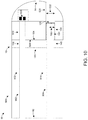
- FIG. 10 is a cross-sectional view of an instrument port according to one or more embodiments.
- a gasket for a medical device includes a flexible base, a flexible hollow body, and a multi-leaflet valve.
- the flexible hollow body extends from a hole defined in the flexible base.
- a flexible hollow body channel is defined in the flexible hollow body and aligned with the hole.
- the multi-leaflet valve is disposed at the distal end of the flexible hollow body.
- the multi-leaflet valve is configured to open in response to a force that is greater than or equal to a threshold force. However, the multi-leaflet valve is configured to remain closed in response to a force that is lower than a threshold force.
- the multi-leaflet valve is also configured to remain closed when the pressure differential across the multi-leaflet valve is lower than a threshold pressure differential, and it is configured to open when the pressure differential across the multi-leaflet valve is higher than a threshold pressure differential.
- the second threshold pressure differential (sometimes referred to as the “cracking pressure”) and second threshold force required to open the multi-leaflet valve in a proximal direction is significantly higher than the first threshold pressure differential and the first threshold force required to open the multi-leaflet valve in a distal direction, such that the multi-leaflet valve effectively operates as one-way valve in the distal direction to allow a surgical instrument to pass through in the distal direction.
- the pressure on the distal side of the multi-leaflet valve is higher than the pressure on the proximal side of the multi-leaflet valve, which is exposed to air.
- the multi-leaflet valve is configured so that the pressure differential across the multi-leaflet valve due to its exposure to bodily fluids is significantly lower than the second threshold pressure differential (or cracking pressure) needed to open the multi-leaflet valve in a proximal direction.
- the multi-leaflet valve opens in response to a force provided by an instrument that is inserted through the flexible hollow body channel in a distal direction, the force greater than or equal to the first threshold force.
- the multi-leaflet valve When the multi-leaflet valve is opened, it exerts an inward force against the instrument and closes when the instrument is removed.
- the multi-leaflet valve remains closed, and maintains a fluid seal, in response to a pressure differential across the multi-leaflet valve that is lower than the threshold pressure differential.
- the multi-leaflet valve remains closed when a fluid, such as a liquid (e.g., saline), flows into the flexible hollow body channel and onto the proximal side of the multi-leaflet valve to clean the flexible hollow body channel before an instrument is inserted therethrough.
- a fluid such as a liquid (e.g., saline)
- the liquid can be removed by applying negative pressure (e.g., a vacuum) to one or more fluid return channels that is/are in fluid communication with the proximal end of the flexible hollow body channel.
- the multi-leaflet valve also remains closed when it is exposed to fluids (e.g., bodily fluids) on the distal side of the multi-leaflet valve, for example when the gasket is inserted into a surgical site of a patient (e.g., when the gasket is disposed in a medical instrument such as an instrument port), as discussed above.
- fluids e.g., bodily fluids
- the multi-leaflet valve is configured so that its cracking pressure (i.e., the second threshold pressure differential required to open the multi-leaflet valve in the proximal direction to allow bodily fluids to pass through in a proximal direction) or second threshold force, in a proximal direction, is significantly higher than the first threshold pressure differential or the first threshold force required to open the multi-leaflet valve in a distal direction (e.g., a force applied by an instrument when it is inserted through the multi-leaflet valve).
- the multi-leaflet valve effectively operates as a one-way valve.
- the flexible hollow body is configured to have a relaxed state and a compressed state.
- a conduit e.g., in a medical device such as an instrument port
- the flexible hollow body transitions to the compressed state.
- the flexible hollow body and optionally the flexible hollow body channel have a first shape (e.g., an irregular shape) in the relaxed state and a second shape (e.g., a second irregular shape, or a regular shape such as a circular or annular shape) in the compressed state.
- the flexible hollow body exerts an outward force against the conduit wall to secure or partially secure the flexible hollow body to the conduit wall (e.g., to a portion of the medical device).
- the compressed state also causes the multi-leaflet valve to close, which increases the threshold force or threshold pressure differential (e.g., cracking pressure) needed to open the multi-leaflet valve in both directions (i.e., in the proximal and distal directions).
- threshold force or threshold pressure differential e.g., cracking pressure
- FIG. 1 is a perspective view of a gasket 10 for creating a fluid seal in a medical device according to one or more embodiments.
- the gasket 10 includes a flexible base 100 , a flexible hollow body 110 , and a multi-leaflet valve 120 .
- the gasket 10 e.g., the flexible base 100 , the flexible hollow body 110 , and/or the multi-leaflet valve 120
- the gasket 10 comprises or consists of silicone (e.g., 70 A durometer silicone).
- a first hole 140 and an optional second hole 130 are defined in the flexible base 100 .
- the second hole 130 is circular in FIG. 1 but it can be another shape (e.g., an oval, a square, a rectangle, etc.) in other embodiments.
- the second hole 130 is arranged to align with a channel in a medical device, for example to pass wires or cables therethrough.
- the second hole 130 is arranged to align with an imaging channel in an instrument port, and electrical wires (e.g., for power, data, and/or controls) extend through the imaging channel, including the second hole 130 , to a camera and/or a light source at the distal end (e.g., in an imaging bulb) of the instrument port.
- electrical wires e.g., for power, data, and/or controls
- the flexible hollow body 110 extends from the first hole 140 defined in the flexible base 100 .
- a proximal end 112 of the flexible hollow body 110 is disposed on the flexible base 100 such that a channel 150 (not illustrated in FIG. 1 ) in the flexible hollow body 110 is aligned with the first hole 140 .
- FIG. 1 illustrates the flexible hollow body 110 in a relaxed state where the cross-sectional shape (e.g., a first shape 111 ) of the flexible hollow body 110 is irregular, where the cross section is parallel to a surface 105 of the flexible base 100 . In the embodiment illustrated in FIG. 1 , the surface 105 is planar.
- the flexible hollow body 110 is configured to have a compressed state when the flexible hollow body 110 is inserted (e.g., press fit) into a channel of a medical device.
- the cross-sectional shape of the flexible hollow body 110 in a plane parallel to the surface 105 of the flexible base 100 , at least partially conforms to the cross-sectional shape of the channel.
- the cross-sectional shape of the flexible hollow body 110 in the compressed state can be another irregular shape or it can be circular or annular to conform to the circular cross-sectional shape of the tubular channel.
- the cross-sectional shape of the flexible hollow body 110 in the compressed state can be an oval or an oval ring to conform to the cross-sectional shape of the channel. Inserting the flexible hollow body 110 into a channel of a medical device, such that the flexible hollow body 110 is in a compressed state, can cause a wall 114 of the flexible hollow body 110 to exert an outward force against the channel wall. The outward force of the wall 114 can cause the wall 114 and the channel wall to be in direct physical contact with each other to secure or partially secure the flexible hollow body 110 to the channel wall, thereby securing or partially securing the gasket 10 to the medical device.
- the multi-leaflet valve 120 is disposed on a distal end 116 of the flexible hollow body 110 .
- the multi-leaflet valve 120 includes 3 leaflets 122 .
- a slit 124 separates each leaflet 122 from an adjacent leaflet 122 .
- the multi-leaflet valve 120 has more than 3 leaflets 122 (e.g., 4 leaflets to 10 leaflets) or only 2 leaflets 122 .
- the exposed surface 125 of the multi-leaflet valve 120 curves towards the flexible hollow body 110 such that a center 128 of the multi-leaflet valve 120 is disposed further away from the flexible hollow body 110 than an edge 129 of the multi-leaflet valve 120 .
- the exposed surface 125 can be concave.
- the exposed surface 125 can be planar or substantially planar.
- the exposed surface 125 can be convex.
- the multi-leaflet valve 120 is configured to open when at least a first minimum or a first threshold force is applied to the multi-leaflet valve 120 in a first direction, for example when a surgical instrument is inserted through the channel 150 in the flexible hollow body 110 from its proximal end 112 to its distal end 116 .
- a surgical instrument is inserted through the multi-leaflet valve 120
- the force applied by the surgical instrument in the distal direction causes the leaflets 122 to open.
- the surgical instrument must be inserted with a force that is greater than the first minimum or the first threshold force required to open the leaflets 122 and multi-leaflet valve 120 in the distal direction.
- the leaflets 122 exert an inward force towards the surgical instrument so that they close when the surgical instrument is removed.
- the operating pressure differential across the multi-leaflet valve 120 is lower than a minimum pressure differential, the multi-leaflet valve 120 remains closed and a seal is maintained.
- the operating pressure differential is the difference between the pressure on the proximal and distal sides of the multi-leaflet valve.
- a first pressure can be applied when a fluid, such as saline, is introduced in the channel 150 in the flexible hollow body, for example to flush the channel 150 before a surgical instrument is inserted through the multi-leaflet valve 120 .
- a negative pressure can also be applied to one or more fluid return channels that is/are in fluid communication with the proximal end of the channel 150 with a vacuum source.
- a second pressure is applied when it is exposed to bodily fluids, such as when the gasket 10 is inserted into a surgical site in a patient as a component of an instrument port.
- the multi-leaflet valve 120 is configured such that the minimum or threshold pressure differential (e.g., a second threshold pressure differential) needed to open the multi-leaflet valve 120 in a proximal direction (e.g., the cracking pressure), when the second pressure is higher than the first pressure, is significantly greater (e.g., an order of magnitude higher or between 2-10 times higher or any value or range therebetween) than the typical or maximum possible operating pressure differential across the multi-leaflet valve 120 when the multi-leaflet valve 120 is exposed to bodily fluids such as blood.
- a second threshold pressure differential e.g., a second threshold pressure differential
- the compression of the flexible hollow body 110 causes the channel wall to exert an inward force against the leaflets 122 of the multi-leaflet valve 120 , which forces them closed and increases the minimum or threshold pressure differential needed to open the multi-leaflet valve 120 in a proximal direction to allow bodily fluids (e.g., blood) to flow in a proximal direction through the multi-leaflet valve 120 .
- bodily fluids e.g., blood
- the multi-leaflet valve 120 is further configured such that the minimum or threshold pressure differential (e.g., a first threshold pressure differential) needed to open the multi-leaflet valve 120 in a distal direction, when the first pressure is greater than the second pressure, is higher than the typical pressure differential across the multi-leaflet valve 120 when a fluid, such as saline, is introduced in the channel 150 in the flexible hollow body, such as to flush the channel 150 and the multi-leaflet valve 120 .
- a first threshold pressure differential e.g., a first threshold pressure differential
- the multi-leaflet valve 120 is configured so that its cracking pressure (i.e., the second threshold pressure differential required to open the multi-leaflet valve 120 in a proximal direction to allow bodily fluids to pass through the multi-leaflet valve 120 in the proximal direction) is significantly higher than the first threshold pressure differential required to open the multi-leaflet valve 120 in a distal direction.
- its cracking pressure i.e., the second threshold pressure differential required to open the multi-leaflet valve 120 in a proximal direction to allow bodily fluids to pass through the multi-leaflet valve 120 in the proximal direction
- the multi-leaflet valve 120 is also configured so that the second minimum or the second threshold force required to open the multi-leaflet valve 120 in a proximal direction is significantly higher (e.g., an order of magnitude higher or between 2-10 times higher or any value or range therebetween) than the first minimum or the first threshold force required to open the multi-leaflet valve 120 in a distal direction (e.g., to allow a surgical instrument to pass through).
- the multi-leaflet valve 120 effectively operates as a one-way valve.
- FIG. 2 is a top view of the gasket 10 illustrated in FIG. 1 to further illustrate the irregular cross-sectional shape (e.g., first shape 111 ) of the flexible hollow body 110 .
- the cross-section shape of the flexible hollow body 110 is generally triangular with deformable contact points 170 at the “corners” of the triangle.
- Each leaflet 122 of the multi-leaflet valve 120 is aligned with a respective deformable contact point 170 such that an inward force applied to each deformable contact point 170 causes the respective leaflet 122 to close, thereby increasing the minimum pressure differential (e.g., the cracking pressure) needed to open the multi-leaflet valve 120 .
- the minimum pressure differential e.g., the cracking pressure
- Each slit 124 of the multi-leaflet valve 120 is aligned with (i.e., orthogonal to) a respective side 180 of the triangle (i.e., the region between adjacent deformable contact points 170 ). In other embodiments, each slit 124 is aligned with a corresponding deformable contact point 170 . In yet other embodiments, each slit is aligned at an angle (other than 90 degrees) with respect to a respective side 180 of the triangle.
- the multi-leaflet valve 120 can have more than 3 leaflets 122 (e.g., 4 leaflets to 10 leaflets) or only 2 leaflets 122 . Therefore, the multi-leaflet valve 120 can have only 2 or 3 or more (e.g., 4 to 10) deformable contact points 170 since each leaflet 122 is aligned with a corresponding deformable contact point 170 .
- FIG. 3 is a side view of the gasket 10 illustrated in FIGS. 1 and 2 taken from an edge 102 of the flexible base 100 .
- Representative dimensions in inches are illustrated in FIG. 3 , but it is noted that these dimensions are exemplary and are not intended to be limiting.
- FIG. 4 is a cross-sectional view of the gasket 10 through line A-A in FIG. 3 .
- the cross-sectional view in FIG. 4 reveals the channel 150 defined in the flexible hollow body 110 .
- the channel 150 is aligned with and extends from the first hole 140 .
- Representative dimensions (in inches) are illustrated in FIG. 4 , but it is noted that these dimensions are exemplary and are not intended to be limiting.
- FIG. 5 is a side view of an assembly 50 that includes a bulb 500 that can be mechanically coupled to the gasket 10 , according to one or more embodiments.
- the bulb 500 includes first and second channels 510 , 520 .
- An imaging system 530 e.g., a camera and an imaging source
- the first channel 510 in the bulb 500 is aligned with the second hole 130 in the gasket 10 .
- the second channel 520 defined by opposing walls 525 , is configured to receive the flexible hollow body 110 including multi-leaflet valve 120 .
- the cross-sectional radius 522 of the second channel 520 is smaller than the largest cross-sectional radius 160 of the flexible hollow body 110 in its relaxed state. In the arrangement illustrated in FIG. 5 , the flexible hollow body 110 of gasket 10 is in the relaxed state.
- the gasket 10 is placed against (e.g., in direct physical contact with) the bulb 500 , such that the surface 105 (e.g., the distal surface) of the base 100 is disposed against a proximal side 504 of the bulb 500 , as illustrated in FIG. 6 .
- the flexible hollow body 110 is inserted into the second channel 520 and the second hole 130 is disposed adjacent to and aligned with the first channel 510 . Since the cross-sectional radius 522 of the second channel 520 is smaller than the largest cross-sectional radius 160 of the flexible hollow body 110 in its relaxed state, the flexible hollow body 110 is press fit into the second channel 520 .
- the press-fitting causes the flexible hollow body 110 to transition from a relaxed state to a compressed state, as discussed herein.
- FIG. 7 is a cross-sectional view of the flexible hollow body 110 through line 5 - 5 in FIG. 5 .
- the flexible hollow body 110 is in a relaxed state in which the cross-sectional shape (e.g., first shape 111 ) of the flexible hollow body 110 and the channel 150 is irregular. Since the channel 150 is defined by the interior surface 714 of the wall 114 of the flexible hollow body 110 , the cross-sectional shape of the wall 114 generally corresponds to the cross-sectional shape of the channel 150 . Thus, the channel 150 has the same or substantially the same cross-sectional shape as the flexible hollow body 110 .
- FIG. 7 also illustrates the largest cross-sectional radius 160 of the flexible hollow body 110 .
- the largest cross-sectional radius 160 can be determined by the length of the longest line that extends from the center or approximate center 155 of the channel 150 to the wall 114 (e.g., to an external surface of the wall 114 ) of the flexible hollow body 110 .
- the largest cross-sectional radius 160 extends to the deformable contact points 170 , which are disposed further from the center or approximate center 155 of the channel 150 than the other portions of the wall 114 .
- FIG. 8 is a cross-sectional view of the flexible hollow body 110 through line 6 - 6 in FIG. 6 .
- the flexible hollow body 110 is in a compressed state in which the cross-sectional shape of the flexible hollow body 110 at least partially conforms to the cross-sectional shape of the wall 525 that defines the second channel 520 .
- the deformable contact points 170 are compressed inwardly such that the largest cross-sectional radius 160 is equal to (or slightly smaller than) the cross-sectional radius of the second channel 520 .
- This compression causes the deformable contact points 170 to exert an outward force against the wall 525 , which at least partially secures the flexible hollow body 110 to the wall 525 of the second channel 520 .
- the compression also causes the leaflets 122 of the multi-leaflet valve 120 to close, which increases the cracking pressure, the first and second threshold forces, and the first and second threshold pressure differentials of the multi-leaflet valve 120 , as discussed above.
- the maximum amount or percentage of deformation of the deformable contact points 170 without damaging the wall 114 is a function of the cross-sectional geometry of the flexible hollow body 110 and the material properties (e.g., hardness) of the flexible hollow body 110 .
- the deformable contact points can deform by a first percentage (e.g., 10%) as indicated by line 172 (e.g., with respect to undeformed contact point 170 ) or by a second percentage (e.g., 100%) as indicated by line 174 .
- a first percentage e.g. 10%
- second percentage e.g. 100%
- the amount or percentage of deformation can range from about 1% to about 100% or higher, and can be customizable based on the geometry and/or material properties of the flexible hollow body 110 and the difference between the largest cross-sectional radius 160 in the uncompressed state and the cross-sectional radius 522 of the second channel 520 .
- the cross-sectional shape (e.g., second shape 211 ) of the flexible hollow body 110 in the compressed state is a circle or annulus (e.g., a regular shape), which conforms to the circular or annular cross-sectional shape of the second channel 520 and wall 525 , as illustrated in FIG. 9 .
- the largest cross-sectional radius 160 of the flexible hollow body 110 is equal to (or slightly smaller than) the cross-sectional radius 860 of the flexible hollow body 110 .
- the wall 114 of the flexible hollow body 110 in the compressed state forms a circle or an annulus
- the corresponding cross-sectional shape of the channel 150 is a circle.
- the cross-sectional shapes of the flexible hollow body 110 , the wall 525 , and the second channel 520 can be other shapes (e.g., ovals or oval rings), as discussed above.
- FIG. 10 is a cross-sectional view of an instrument port 90 according to one or more embodiments.
- the instrument port 90 includes a port body 900 , the gasket 10 , and the bulb 500 .
- An imaging channel 912 and an instrument channel 904 are defined in the port body 900 .
- the gasket 10 is disposed between the port body 900 and the bulb 500 .
- the second hole 130 in the gasket 10 is aligned with the first channel 902 in the port body 900 and with the first channel 510 in the bulb 500 to form a continuous imaging channel 912 .
- the imaging channel 912 extends from a proximal end 92 of the instrument port 90 to the imaging system 530 , which is disposed within the bulb 500 .
- the first hole 140 and channel 150 in the gasket 10 are aligned with the second channel 904 in the port body 900 and with the second channel 520 in the bulb 500 to form a continuous instrument channel 912 .
- the instrument channel 912 extends from the proximal end 92 to a distal end 94 of the instrument port 90 .
- the distal end 94 of the instrument port 90 can be inserted into a surgical site or orifice of a subject to guide an instrument (e.g., a surgical instrument) thereto.
- an instrument e.g., a surgical instrument
- the instrument port 90 is inserted into the surgical site or orifice of the subject, it is exposed to bodily fluids such as blood, saliva, and/or urine.
- the multi-leaflet valve 120 is configured (e.g., due to its high cracking pressure or second threshold pressure differential) to prevent such bodily fluids from entering the channel 150 and flowing towards the proximal end 92 of the instrument port 90 .
- the flexible base 100 disposed between the first and second holes 130 , 140 further prevents any fluid from passing into the imaging channel 912 .
- the multi-leaflet valve 120 is configured to open to allow the instrument to pass through when the instrument applies at least a first minimum force or a first threshold force against the multi-leaflet valve 120 in a distal direction.
- the first minimum force or first pressure differential required to open the multi-leaflet valve 120 in the distal direction is significantly lower than the second minimum or second threshold force or second pressure differential, respectively, required to open the multi-leaflet valve 120 in the proximal direction such that the multi-leaflet valve 120 effectively operates as a one-way valve in the distal direction.
- the leaflets 122 apply an inward force against the instrument to close the multi-leaflet valve 120 after the instrument is removed.
- the multi-leaflet valve 120 is also configured to remain closed when the pressure differential across the multi-leaflet valve 120 is lower than the first or second threshold pressure differential, as discussed above.
- one or more wires can pass through the imaging channel 912 to connect the imaging system 530 with one or more external components, such as a power source and/or a computer.
- the wires can provide power, data, and/or control signals to/from the imaging system 530 .
- the imaging system 530 can be used to view the instrument as it exits the imaging channel 914 to ensure proper placement of the instrument and/or to guide the procedure.
Abstract
Description
Claims (27)
Priority Applications (1)
| Application Number | Priority Date | Filing Date | Title |
|---|---|---|---|
| US15/917,126 US11213316B2 (en) | 2018-03-09 | 2018-03-09 | Gasket with multi-leaflet valve for surgical port apparatus |
Applications Claiming Priority (1)
| Application Number | Priority Date | Filing Date | Title |
|---|---|---|---|
| US15/917,126 US11213316B2 (en) | 2018-03-09 | 2018-03-09 | Gasket with multi-leaflet valve for surgical port apparatus |
Publications (2)
| Publication Number | Publication Date |
|---|---|
| US20190274727A1 US20190274727A1 (en) | 2019-09-12 |
| US11213316B2 true US11213316B2 (en) | 2022-01-04 |
Family
ID=67842909
Family Applications (1)
| Application Number | Title | Priority Date | Filing Date |
|---|---|---|---|
| US15/917,126 Active 2039-10-23 US11213316B2 (en) | 2018-03-09 | 2018-03-09 | Gasket with multi-leaflet valve for surgical port apparatus |
Country Status (1)
| Country | Link |
|---|---|
| US (1) | US11213316B2 (en) |
Citations (91)
| Publication number | Priority date | Publication date | Assignee | Title |
|---|---|---|---|---|
| US2243992A (en) | 1939-09-09 | 1941-06-03 | Wappler Frederick Charles | Flexible operating instrument |
| US2767705A (en) | 1954-10-08 | 1956-10-23 | Technical Oil Tool Corp | Sigmoidoscope with suction attachment for immobilizing adjacent tissue |
| US4180068A (en) | 1978-04-13 | 1979-12-25 | Motion Control, Incorporated | Bi-directional flow catheter with retractable trocar/valve structure |
| US4201199A (en) | 1978-01-13 | 1980-05-06 | Smith Donald C | Endoscope attachment to a viewing instrument for insertion into the uterine cavity |
| US4233982A (en) | 1977-11-24 | 1980-11-18 | Richard Wolf Gmbh | Trocar sleeves having a ball valve |
| US4436087A (en) | 1977-12-11 | 1984-03-13 | Kabushiki Kaisha Medos Kenkyusho | Bioptic instrument |
| US4535773A (en) | 1982-03-26 | 1985-08-20 | Inbae Yoon | Safety puncturing instrument and method |
| US5025778A (en) | 1990-03-26 | 1991-06-25 | Opielab, Inc. | Endoscope with potential channels and method of using the same |
| US5217001A (en) | 1991-12-09 | 1993-06-08 | Nakao Naomi L | Endoscope sheath and related method |
| US5256149A (en) | 1992-02-14 | 1993-10-26 | Ethicon, Inc. | Trocar having transparent cannula and method of using |
| US5261391A (en) | 1991-08-23 | 1993-11-16 | Kabushiki Kaisha Machida Seisakusho | Threaded flexible guide tube for endoscope |
| US5279551A (en) | 1992-01-29 | 1994-01-18 | Vascular Products, Inc. | Trocar catheter |
| US5352206A (en) | 1993-03-31 | 1994-10-04 | Laparomed Corporation | Trocar system having penetration indicator |
| US5441503A (en) | 1988-09-24 | 1995-08-15 | Considine; John | Apparatus for removing tumors from hollow organs of the body |
| US5454791A (en) | 1993-09-07 | 1995-10-03 | United States Surgical Corporation | Trocar with tissue penetration pressure indicator |
| US5454807A (en) | 1993-05-14 | 1995-10-03 | Boston Scientific Corporation | Medical treatment of deeply seated tissue using optical radiation |
| US5458633A (en) | 1994-05-24 | 1995-10-17 | Bailey; Robert W. | Irrigating laparoscopic cannula or trocar |
| US5622626A (en) | 1994-04-15 | 1997-04-22 | Pall Corporation | Multiple compartment filter and method for processing parenteral fluid |
| US5632782A (en) | 1994-09-01 | 1997-05-27 | Clariant Finance (Bvi) Ltd. | Exhaust dyeing process for sulphur dyes |
| US5658298A (en) | 1993-11-09 | 1997-08-19 | Inamed Development Company | Laparoscopic tool |
| US5660175A (en) | 1995-08-21 | 1997-08-26 | Dayal; Bimal | Endotracheal device |
| US5752970A (en) | 1995-02-03 | 1998-05-19 | Yoon; Inbae | Cannula with distal end valve |
| WO1998024501A1 (en) | 1996-11-26 | 1998-06-11 | Baxter International Inc. | Multiple lumen access device |
| US5788676A (en) | 1996-03-25 | 1998-08-04 | Yoon; Inbae | Endoscopic portal having multiple universal seals and method of introducing instruments therethrough |
| US5797960A (en) | 1993-02-22 | 1998-08-25 | Stevens; John H. | Method and apparatus for thoracoscopic intracardiac procedures |
| WO1998040016A2 (en) | 1997-03-12 | 1998-09-17 | Advanced Closure Systems, Inc. | Universal introducer |
| US5842971A (en) | 1996-05-22 | 1998-12-01 | Yoon; Inbae | Optical endoscopic portals and methods of using the same to establish passages through cavity walls |
| US5855569A (en) | 1996-03-14 | 1999-01-05 | Fuji Photo Optical Co., Ltd. | Expandable anchor mechanism for use in endoscopic biopsy channel |
| US5899915A (en) | 1996-12-02 | 1999-05-04 | Angiotrax, Inc. | Apparatus and method for intraoperatively performing surgery |
| US5928218A (en) | 1994-12-16 | 1999-07-27 | Gelbfish; Gary A. | Medical material removal method and associated instrumentation |
| US5941815A (en) | 1996-12-05 | 1999-08-24 | Helix Medical, Inc. | Sigmoid splint device for endoscopy |
| US5968060A (en) | 1997-02-28 | 1999-10-19 | Ethicon Endo-Surgery, Inc. | Ultrasonic interlock and method of using the same |
| US5993471A (en) | 1996-10-22 | 1999-11-30 | Erol D. Riza | Trocar assembly |
| US6017333A (en) | 1995-04-13 | 2000-01-25 | Bailey; Robert W. | Irrigating laparoscopic cannula |
| US6033426A (en) | 1997-07-29 | 2000-03-07 | Olympus Optical Co., Ltd. | Access device for surgical treatment |
| US6129713A (en) | 1998-08-11 | 2000-10-10 | Embol-X, Inc. | Slidable cannula and method of use |
| US6178346B1 (en) | 1998-10-23 | 2001-01-23 | David C. Amundson | Infrared endoscopic imaging in a liquid with suspended particles: method and apparatus |
| US6287280B1 (en) | 1999-09-07 | 2001-09-11 | Merit Medical Systems, Inc. | Hemostasis valve apparatus with integral introducer |
| US6293282B1 (en) | 1996-11-05 | 2001-09-25 | Jerome Lemelson | System and method for treating select tissue in living being |
| US6309345B1 (en) | 1997-08-21 | 2001-10-30 | Paul Stelzer | Minimally invasive surgery device |
| US6315714B1 (en) | 1998-11-30 | 2001-11-13 | Fuji Photo Optical Co., Ltd. | Endoscope insertion guide pipe |
| US20020026094A1 (en) | 1993-02-22 | 2002-02-28 | Roth Alex T. | Devices for less-invasive intracardiac interventions |
| US6379326B1 (en) | 1998-11-19 | 2002-04-30 | William Cimino | Lipoplasty method |
| US20020068853A1 (en) | 2000-04-10 | 2002-06-06 | Doron Adler | Intra vascular imaging method and apparatus |
| US20020111585A1 (en) | 2001-02-13 | 2002-08-15 | Scimed Life Systems, Inc. | Hemostasis valve |
| US20020161378A1 (en) | 2000-06-20 | 2002-10-31 | Downing Stephen W. | Apparatuses and methods for performing minimally invasive diagnostic and surgical procedures inside of a beating heart |
| US6503192B1 (en) | 1999-05-18 | 2003-01-07 | Pentax Corporation | Insertion facilitating device for intestinal endoscope |
| US20030009079A1 (en) | 2001-07-06 | 2003-01-09 | Opticon Medical, Inc. | Urinary flow control valve |
| US6554793B1 (en) | 1998-04-07 | 2003-04-29 | Stm Medizintechnik Starnberg Gmbh | Flexible trocar with an upturning tube system |
| US6641562B1 (en) | 2000-05-10 | 2003-11-04 | Hps Medical, Inc. | Apparatus and method of intravenous fluid infusion |
| US6685665B2 (en) | 2000-09-08 | 2004-02-03 | Pall Corporation | Cannula assembly |
| US6689085B1 (en) | 1996-07-11 | 2004-02-10 | Eunoe, Inc. | Method and apparatus for treating adult-onset dementia of the Alzheimer's type |
| EP1426072A1 (en) | 2002-12-05 | 2004-06-09 | Ethicon Endo-Surgery, Inc. | Locally-propelled, intraluminal device with cable loop track |
| US6749559B1 (en) | 1999-05-27 | 2004-06-15 | Olympus Winter & Ibe Gmbh | Endoscope |
| US20040116897A1 (en) | 2000-07-12 | 2004-06-17 | Walid Aboul- Hosn | Minimally invasive bypass system and related methods |
| US20040193191A1 (en) | 2003-02-06 | 2004-09-30 | Guided Delivery Systems, Inc. | Devices and methods for heart valve repair |
| US20040191897A1 (en) | 2003-03-31 | 2004-09-30 | The Cleveland Clinic Foundation | Apparatus and method for harvesting bone marrow |
| WO2004112652A2 (en) | 2003-06-20 | 2004-12-29 | Medtronic Vascular, Inc. | Device, system, and method for contracting tissue in a mammalian body |
| WO2005051175A2 (en) | 2003-11-20 | 2005-06-09 | Children's Medical Center Corporation | Trocar for use during endoscopy |
| US20050197530A1 (en) | 2003-09-25 | 2005-09-08 | Wallace Daniel T. | Balloon visualization for traversing a tissue wall |
| US20050234298A1 (en) | 2004-01-29 | 2005-10-20 | Cannuflow Incorporated | Atraumatic arthroscopic instrument sheath |
| US20050234296A1 (en) | 2004-04-14 | 2005-10-20 | Usgi Medical Inc. | Method and apparatus for obtaining endoluminal access |
| US20060264708A1 (en) | 2005-05-20 | 2006-11-23 | Karl Storz Endovision | Liner for endoscope working channel |
| US20070066869A1 (en) | 2005-09-21 | 2007-03-22 | David Hoffman | Endoscopic assembly including cap and sheath |
| WO2007081800A2 (en) | 2006-01-05 | 2007-07-19 | Children's Medical Center Corporation | Instrument port for minimally invasive cardiac surgery |
| US20070197896A1 (en) | 2005-12-09 | 2007-08-23 | Hansen Medical, Inc | Robotic catheter system and methods |
| US7442167B2 (en) | 2002-03-22 | 2008-10-28 | Ethicon Endo-Surgery, Inc. | Integrated visualization system |
| US20090048486A1 (en) | 2007-08-08 | 2009-02-19 | Wilson-Cook Medical Inc. | Distal Tip for an Endoscope |
| US7537562B2 (en) | 2004-01-28 | 2009-05-26 | Fujinon Corporation | Endoscope apparatus |
| US20100286475A1 (en) | 2009-05-08 | 2010-11-11 | Boston Scientific Scimed, Inc. | Endoscope with distal tip having encased optical components and display orientation capabilities |
| US7914444B2 (en) | 2003-12-15 | 2011-03-29 | Olympus Corporation | Endoscope system and endoscope |
| WO2011047339A2 (en) | 2009-10-15 | 2011-04-21 | Inventio Llc | Disposable and reusable complex shaped see-through endoscope |
| US20110245619A1 (en) * | 2010-04-01 | 2011-10-06 | Ethicon Endo-Surgery, Inc. | Surgical access device |
| US20110288372A1 (en) | 2008-12-10 | 2011-11-24 | Lasse Kjeld Gjoeske Petersen | Endoscope having a camera housing and method for making a camera housing |
| US20110295072A1 (en) * | 2006-04-20 | 2011-12-01 | Boston Scientific Scimed, Inc. | Imaging assembly with transparent distal cap |
| EP2433551A1 (en) | 2010-09-28 | 2012-03-28 | Fujifilm Corporation | Endoscope apparatus |
| US20120209074A1 (en) | 2011-02-16 | 2012-08-16 | James Sidney Titus | Optical coupler for an endoscope |
| US8287447B2 (en) | 2007-08-29 | 2012-10-16 | Minos Medical | Outer tube for natural orifice surgery |
| US20130066281A1 (en) * | 2011-02-22 | 2013-03-14 | Medtronic Minimed, Inc. | Sealing assembly with pinch valve structure for a fluid infusion device having a needled fluid reservoir |
| US8425407B2 (en) | 2008-09-12 | 2013-04-23 | Olympus Medical Systems Corp. | Endoscope insertion portion |
| US8491631B2 (en) | 2006-01-30 | 2013-07-23 | Children's Medical Center Corporation | Tissue tack |
| US20130245371A1 (en) | 2002-05-30 | 2013-09-19 | The Board Of Trustees Of The Leland Stanford Junior University | Apparatus and methods for coronary sinus access |
| US20140213848A1 (en) | 2012-10-10 | 2014-07-31 | Mosheh T. MOSKOWITZ | Endoscopic surgical system |
| US20140213847A1 (en) | 2011-06-17 | 2014-07-31 | Research Institute At Nationwide Children's Hospit | Endoscopic foreign body retrieval |
| US20140221749A1 (en) | 2013-02-01 | 2014-08-07 | Deka Products Limited Partnership | Endoscope with Pannable Camera |
| US8926502B2 (en) | 2011-03-07 | 2015-01-06 | Endochoice, Inc. | Multi camera endoscope having a side service channel |
| US20150313633A1 (en) | 2014-05-05 | 2015-11-05 | Rainbow Medical Ltd. | Pericardial access device |
| US9451875B2 (en) | 2012-12-07 | 2016-09-27 | Cook Medical Technologies Llc | Flexible lens |
| US9459442B2 (en) | 2014-09-23 | 2016-10-04 | Scott Miller | Optical coupler for optical imaging visualization device |
| US20160367120A1 (en) | 2015-06-19 | 2016-12-22 | Children's Medical Center Corporation | Optically Guided Surgical Devices |
| US20170231477A1 (en) | 2016-02-12 | 2017-08-17 | Children's Medical Center Corporation | Instrument port with integrated imaging system |
-
2018
- 2018-03-09 US US15/917,126 patent/US11213316B2/en active Active
Patent Citations (105)
| Publication number | Priority date | Publication date | Assignee | Title |
|---|---|---|---|---|
| US2243992A (en) | 1939-09-09 | 1941-06-03 | Wappler Frederick Charles | Flexible operating instrument |
| US2767705A (en) | 1954-10-08 | 1956-10-23 | Technical Oil Tool Corp | Sigmoidoscope with suction attachment for immobilizing adjacent tissue |
| US4233982A (en) | 1977-11-24 | 1980-11-18 | Richard Wolf Gmbh | Trocar sleeves having a ball valve |
| US4436087A (en) | 1977-12-11 | 1984-03-13 | Kabushiki Kaisha Medos Kenkyusho | Bioptic instrument |
| US4201199A (en) | 1978-01-13 | 1980-05-06 | Smith Donald C | Endoscope attachment to a viewing instrument for insertion into the uterine cavity |
| US4180068A (en) | 1978-04-13 | 1979-12-25 | Motion Control, Incorporated | Bi-directional flow catheter with retractable trocar/valve structure |
| US4535773A (en) | 1982-03-26 | 1985-08-20 | Inbae Yoon | Safety puncturing instrument and method |
| US5441503A (en) | 1988-09-24 | 1995-08-15 | Considine; John | Apparatus for removing tumors from hollow organs of the body |
| US5025778A (en) | 1990-03-26 | 1991-06-25 | Opielab, Inc. | Endoscope with potential channels and method of using the same |
| US5261391A (en) | 1991-08-23 | 1993-11-16 | Kabushiki Kaisha Machida Seisakusho | Threaded flexible guide tube for endoscope |
| US5217001A (en) | 1991-12-09 | 1993-06-08 | Nakao Naomi L | Endoscope sheath and related method |
| US5279551A (en) | 1992-01-29 | 1994-01-18 | Vascular Products, Inc. | Trocar catheter |
| US5256149A (en) | 1992-02-14 | 1993-10-26 | Ethicon, Inc. | Trocar having transparent cannula and method of using |
| US5797960A (en) | 1993-02-22 | 1998-08-25 | Stevens; John H. | Method and apparatus for thoracoscopic intracardiac procedures |
| US20020026094A1 (en) | 1993-02-22 | 2002-02-28 | Roth Alex T. | Devices for less-invasive intracardiac interventions |
| US5352206A (en) | 1993-03-31 | 1994-10-04 | Laparomed Corporation | Trocar system having penetration indicator |
| US5454807A (en) | 1993-05-14 | 1995-10-03 | Boston Scientific Corporation | Medical treatment of deeply seated tissue using optical radiation |
| US5454791A (en) | 1993-09-07 | 1995-10-03 | United States Surgical Corporation | Trocar with tissue penetration pressure indicator |
| US5658298A (en) | 1993-11-09 | 1997-08-19 | Inamed Development Company | Laparoscopic tool |
| US5622626A (en) | 1994-04-15 | 1997-04-22 | Pall Corporation | Multiple compartment filter and method for processing parenteral fluid |
| US5458633A (en) | 1994-05-24 | 1995-10-17 | Bailey; Robert W. | Irrigating laparoscopic cannula or trocar |
| US5632782A (en) | 1994-09-01 | 1997-05-27 | Clariant Finance (Bvi) Ltd. | Exhaust dyeing process for sulphur dyes |
| US5928218A (en) | 1994-12-16 | 1999-07-27 | Gelbfish; Gary A. | Medical material removal method and associated instrumentation |
| US5752970A (en) | 1995-02-03 | 1998-05-19 | Yoon; Inbae | Cannula with distal end valve |
| US6017333A (en) | 1995-04-13 | 2000-01-25 | Bailey; Robert W. | Irrigating laparoscopic cannula |
| US5660175A (en) | 1995-08-21 | 1997-08-26 | Dayal; Bimal | Endotracheal device |
| US5855569A (en) | 1996-03-14 | 1999-01-05 | Fuji Photo Optical Co., Ltd. | Expandable anchor mechanism for use in endoscopic biopsy channel |
| US5788676A (en) | 1996-03-25 | 1998-08-04 | Yoon; Inbae | Endoscopic portal having multiple universal seals and method of introducing instruments therethrough |
| US5842971A (en) | 1996-05-22 | 1998-12-01 | Yoon; Inbae | Optical endoscopic portals and methods of using the same to establish passages through cavity walls |
| US6689085B1 (en) | 1996-07-11 | 2004-02-10 | Eunoe, Inc. | Method and apparatus for treating adult-onset dementia of the Alzheimer's type |
| US5993471A (en) | 1996-10-22 | 1999-11-30 | Erol D. Riza | Trocar assembly |
| US6293282B1 (en) | 1996-11-05 | 2001-09-25 | Jerome Lemelson | System and method for treating select tissue in living being |
| WO1998024501A1 (en) | 1996-11-26 | 1998-06-11 | Baxter International Inc. | Multiple lumen access device |
| US5899915A (en) | 1996-12-02 | 1999-05-04 | Angiotrax, Inc. | Apparatus and method for intraoperatively performing surgery |
| US5941815A (en) | 1996-12-05 | 1999-08-24 | Helix Medical, Inc. | Sigmoid splint device for endoscopy |
| US5968060A (en) | 1997-02-28 | 1999-10-19 | Ethicon Endo-Surgery, Inc. | Ultrasonic interlock and method of using the same |
| WO1998040016A2 (en) | 1997-03-12 | 1998-09-17 | Advanced Closure Systems, Inc. | Universal introducer |
| US6033426A (en) | 1997-07-29 | 2000-03-07 | Olympus Optical Co., Ltd. | Access device for surgical treatment |
| US6309345B1 (en) | 1997-08-21 | 2001-10-30 | Paul Stelzer | Minimally invasive surgery device |
| US6554793B1 (en) | 1998-04-07 | 2003-04-29 | Stm Medizintechnik Starnberg Gmbh | Flexible trocar with an upturning tube system |
| US6129713A (en) | 1998-08-11 | 2000-10-10 | Embol-X, Inc. | Slidable cannula and method of use |
| US6178346B1 (en) | 1998-10-23 | 2001-01-23 | David C. Amundson | Infrared endoscopic imaging in a liquid with suspended particles: method and apparatus |
| US6379326B1 (en) | 1998-11-19 | 2002-04-30 | William Cimino | Lipoplasty method |
| US6315714B1 (en) | 1998-11-30 | 2001-11-13 | Fuji Photo Optical Co., Ltd. | Endoscope insertion guide pipe |
| US6503192B1 (en) | 1999-05-18 | 2003-01-07 | Pentax Corporation | Insertion facilitating device for intestinal endoscope |
| US6749559B1 (en) | 1999-05-27 | 2004-06-15 | Olympus Winter & Ibe Gmbh | Endoscope |
| US6287280B1 (en) | 1999-09-07 | 2001-09-11 | Merit Medical Systems, Inc. | Hemostasis valve apparatus with integral introducer |
| US20020068853A1 (en) | 2000-04-10 | 2002-06-06 | Doron Adler | Intra vascular imaging method and apparatus |
| US6641562B1 (en) | 2000-05-10 | 2003-11-04 | Hps Medical, Inc. | Apparatus and method of intravenous fluid infusion |
| US20040024414A1 (en) | 2000-06-20 | 2004-02-05 | Downing Stephen W. | Apparatuses and methods for performing minimally invasive diagnostic and surgical procedures inside of a beating heart |
| US20020161378A1 (en) | 2000-06-20 | 2002-10-31 | Downing Stephen W. | Apparatuses and methods for performing minimally invasive diagnostic and surgical procedures inside of a beating heart |
| US20040116897A1 (en) | 2000-07-12 | 2004-06-17 | Walid Aboul- Hosn | Minimally invasive bypass system and related methods |
| US6685665B2 (en) | 2000-09-08 | 2004-02-03 | Pall Corporation | Cannula assembly |
| US20020111585A1 (en) | 2001-02-13 | 2002-08-15 | Scimed Life Systems, Inc. | Hemostasis valve |
| US6520939B2 (en) | 2001-02-13 | 2003-02-18 | Scimed Life Systems, Inc. | Hemostasis valve |
| US20030009079A1 (en) | 2001-07-06 | 2003-01-09 | Opticon Medical, Inc. | Urinary flow control valve |
| US7442167B2 (en) | 2002-03-22 | 2008-10-28 | Ethicon Endo-Surgery, Inc. | Integrated visualization system |
| US20130245371A1 (en) | 2002-05-30 | 2013-09-19 | The Board Of Trustees Of The Leland Stanford Junior University | Apparatus and methods for coronary sinus access |
| EP1426072A1 (en) | 2002-12-05 | 2004-06-09 | Ethicon Endo-Surgery, Inc. | Locally-propelled, intraluminal device with cable loop track |
| US20040111019A1 (en) | 2002-12-05 | 2004-06-10 | Long Gary L. | Locally-propelled, intraluminal device with cable loop track and method of use |
| US20040193191A1 (en) | 2003-02-06 | 2004-09-30 | Guided Delivery Systems, Inc. | Devices and methods for heart valve repair |
| US20040191897A1 (en) | 2003-03-31 | 2004-09-30 | The Cleveland Clinic Foundation | Apparatus and method for harvesting bone marrow |
| WO2004112652A2 (en) | 2003-06-20 | 2004-12-29 | Medtronic Vascular, Inc. | Device, system, and method for contracting tissue in a mammalian body |
| US20050197530A1 (en) | 2003-09-25 | 2005-09-08 | Wallace Daniel T. | Balloon visualization for traversing a tissue wall |
| US8951275B2 (en) | 2003-11-20 | 2015-02-10 | Children's Medical Center Corporation | Trocar for use during endoscopy |
| WO2005051175A2 (en) | 2003-11-20 | 2005-06-09 | Children's Medical Center Corporation | Trocar for use during endoscopy |
| US7914444B2 (en) | 2003-12-15 | 2011-03-29 | Olympus Corporation | Endoscope system and endoscope |
| US7537562B2 (en) | 2004-01-28 | 2009-05-26 | Fujinon Corporation | Endoscope apparatus |
| US20050234298A1 (en) | 2004-01-29 | 2005-10-20 | Cannuflow Incorporated | Atraumatic arthroscopic instrument sheath |
| US20050234296A1 (en) | 2004-04-14 | 2005-10-20 | Usgi Medical Inc. | Method and apparatus for obtaining endoluminal access |
| US20060264708A1 (en) | 2005-05-20 | 2006-11-23 | Karl Storz Endovision | Liner for endoscope working channel |
| US20070066869A1 (en) | 2005-09-21 | 2007-03-22 | David Hoffman | Endoscopic assembly including cap and sheath |
| US20070197896A1 (en) | 2005-12-09 | 2007-08-23 | Hansen Medical, Inc | Robotic catheter system and methods |
| US20160000463A1 (en) | 2006-01-05 | 2016-01-07 | Children S Medical Center Corporation | Instrument Port For Minimally Invasive Cardiac Surgery |
| US20090275893A1 (en) | 2006-01-05 | 2009-11-05 | Dibiasio Christopher | Instrument port for minimally invasive cardiac surgery |
| US9844394B2 (en) | 2006-01-05 | 2017-12-19 | Children's Medical Center Corporation | Instrument port for minimally invasive cardiac surgery |
| US8394015B2 (en) | 2006-01-05 | 2013-03-12 | Children's Medical Center Corporation | Instrument port for minimally invasive cardiac surgery |
| WO2007081800A2 (en) | 2006-01-05 | 2007-07-19 | Children's Medical Center Corporation | Instrument port for minimally invasive cardiac surgery |
| US8491631B2 (en) | 2006-01-30 | 2013-07-23 | Children's Medical Center Corporation | Tissue tack |
| US20110295072A1 (en) * | 2006-04-20 | 2011-12-01 | Boston Scientific Scimed, Inc. | Imaging assembly with transparent distal cap |
| US20090048486A1 (en) | 2007-08-08 | 2009-02-19 | Wilson-Cook Medical Inc. | Distal Tip for an Endoscope |
| US8287447B2 (en) | 2007-08-29 | 2012-10-16 | Minos Medical | Outer tube for natural orifice surgery |
| US8425407B2 (en) | 2008-09-12 | 2013-04-23 | Olympus Medical Systems Corp. | Endoscope insertion portion |
| US20110288372A1 (en) | 2008-12-10 | 2011-11-24 | Lasse Kjeld Gjoeske Petersen | Endoscope having a camera housing and method for making a camera housing |
| US20100286475A1 (en) | 2009-05-08 | 2010-11-11 | Boston Scientific Scimed, Inc. | Endoscope with distal tip having encased optical components and display orientation capabilities |
| US20130281779A1 (en) | 2009-05-08 | 2013-10-24 | Boston Scientific Scimed, Inc. | Endoscope with distal tip having encased optical components and display orientation capabilities |
| WO2011047339A2 (en) | 2009-10-15 | 2011-04-21 | Inventio Llc | Disposable and reusable complex shaped see-through endoscope |
| US20120232342A1 (en) | 2009-10-15 | 2012-09-13 | Boris Reydel | Disposable and reusable comlex shaped see-through endoscope |
| US20110245619A1 (en) * | 2010-04-01 | 2011-10-06 | Ethicon Endo-Surgery, Inc. | Surgical access device |
| EP2433551A1 (en) | 2010-09-28 | 2012-03-28 | Fujifilm Corporation | Endoscope apparatus |
| US20120209074A1 (en) | 2011-02-16 | 2012-08-16 | James Sidney Titus | Optical coupler for an endoscope |
| US20150065795A1 (en) | 2011-02-16 | 2015-03-05 | The General Hospital Corporation | Optical Coupler for an Endoscope |
| US20130066281A1 (en) * | 2011-02-22 | 2013-03-14 | Medtronic Minimed, Inc. | Sealing assembly with pinch valve structure for a fluid infusion device having a needled fluid reservoir |
| US8926502B2 (en) | 2011-03-07 | 2015-01-06 | Endochoice, Inc. | Multi camera endoscope having a side service channel |
| US20140213847A1 (en) | 2011-06-17 | 2014-07-31 | Research Institute At Nationwide Children's Hospit | Endoscopic foreign body retrieval |
| US20140213848A1 (en) | 2012-10-10 | 2014-07-31 | Mosheh T. MOSKOWITZ | Endoscopic surgical system |
| US9451875B2 (en) | 2012-12-07 | 2016-09-27 | Cook Medical Technologies Llc | Flexible lens |
| US20140221749A1 (en) | 2013-02-01 | 2014-08-07 | Deka Products Limited Partnership | Endoscope with Pannable Camera |
| US20150313633A1 (en) | 2014-05-05 | 2015-11-05 | Rainbow Medical Ltd. | Pericardial access device |
| US9709795B2 (en) | 2014-09-23 | 2017-07-18 | Scott Miller | Optical coupler for optical imaging visualization device |
| US9459442B2 (en) | 2014-09-23 | 2016-10-04 | Scott Miller | Optical coupler for optical imaging visualization device |
| US20160367120A1 (en) | 2015-06-19 | 2016-12-22 | Children's Medical Center Corporation | Optically Guided Surgical Devices |
| WO2016205694A1 (en) | 2015-06-19 | 2016-12-22 | Children's Medical Center Corporation | Optically guided surgical devices |
| US20170231477A1 (en) | 2016-02-12 | 2017-08-17 | Children's Medical Center Corporation | Instrument port with integrated imaging system |
| WO2017139629A1 (en) | 2016-02-12 | 2017-08-17 | Children's Medical Center Corporation | Instrument port with integrated imaging system |
Non-Patent Citations (18)
| Title |
|---|
| Ahmed et al.; Initial clinical experience with a novel visualization and virtual electrode radiofrequency ablation catheter to treat atrial flutter; Heart Rhythm Society; 2011; pp. 361-367. |
| Ataollahi et al., "Cardioscopic Tool-Delivery Instrument for Beating-Heart Surgery," IEEE ASME Transactions on Mechatronics, 21(1):1-1 (abstract), Jan. 2015 [retrieved on Apr. 15, 2019]. Retrieved from the internet: <URL:https://www.researchgate.net/publication/283309805_Cardioscopic_Tool-Delivery_Instrumentfor_Beating-Heart_Surgery>. |
| Ataollahi et al., "Cardioscopic Tool-Delivery Instrument for Beating-Heart Surgery," IEEE ASME Transactions on Mechatronics, vol. 21, No. 1, Feb. 2016, pp. 584-590. |
| European Patent Office, "Extended European Search Report", App. No. 17750861.1, dated Sep. 30, 2019, European Patent Office. |
| Extended European Search Report in European Application No. 16812547.4, dated Feb. 21, 2019, 8 pages. |
| Extended European Search Report issued in EP07716358.2 dated Apr. 24, 2014. |
| International Search Report & Written Opinion, PCT/US07/00270, dated Oct. 1, 2007. |
| International Search Report & Written Opinion, PCT/US17/17445, dated May 5, 2017, 16 pages. |
| International Search Report and Written Opinion in International Application No. PCT/US17/17445, dated Jun. 6, 2017. |
| International Search Report and Written Opinion in International Application No. PCT/US2016/038147, dated Sep. 8, 2016. |
| ISA, "International Search Report", PCT/US2018/021797, dated May 23, 2018. |
| P. Dupont; "Invention Disclosure—Cardioscopes"; May 21, 2015; 5pp. |
| Padala et al.; Transapical beating heart cardioscopy technique for off-pump visualization of heart valves; The Journal of thoracic and Cardiovascular Surgery; vol. 144, No. 1; 2012; pp. 231-234. |
| Shiose et al.; "Cardioscopy-guided surgery: Intracardiac mitral and tricuspid valve repair under direct visualization in the beating heart"; The Journal of thoracic and Cardiovascular Surgery; vol. 142, No. 1; 2011; pp. 199-202. |
| Uchida; "Recent Advances in Percutaneous Cardioscopy"; Curr Cardiovasc Imaging Rep; May 12, 2011; pp. 317-327. |
| Vasilyev et al.; "A Novel Cardioport for Beating-Heart Image-Guided Intracardiac Surgery"; Children's Hospital Boston, Harvard Medical School, Boston, Massachusetts Institute of Technology, Cambridge, Massachusetts; International Society for Minimally Invasive Cardiothoracic Surgery (ISMICS); Jun. 3, 2009. |
| Vasilyev et al.; "A novel cardioport for beating-heart, image-guided intracardiac surgery" The Journal of thoracic and Cardiovascular Surgery; vol. 142, No. 6; Dec. 2011; pp. 1545-1551. |
| Vasilyev et al.; "Three-Dimensional Echo and Videocardioscopy-Guided Atrial Septal Defect Closure"; Annals of Thoracic Surgery; 2006; vol. 82; pp. 1322-1326. |
Also Published As
| Publication number | Publication date |
|---|---|
| US20190274727A1 (en) | 2019-09-12 |
Similar Documents
| Publication | Publication Date | Title |
|---|---|---|
| US11534205B2 (en) | Cannula seal assembly | |
| EP1441801B1 (en) | H-shape duckbill hemostasis valve assembly including guide wire seal | |
| US9017252B2 (en) | Access assembly with flexible cannulas | |
| JP5602137B2 (en) | Valve assembly for breathing system | |
| US8038652B2 (en) | Button cannula | |
| JP2957134B2 (en) | Valve and valved trocar mantle | |
| US7226433B2 (en) | Thrombectomy catheter device having a self-sealing hemostasis valve | |
| US6053861A (en) | Self-closing seal for a medical instrument | |
| US5045075A (en) | Surgical drain apparatus and method | |
| US20060041232A1 (en) | Introducer assembly with suspended seal | |
| US20120313325A1 (en) | Surgical gel seal | |
| JP5252694B2 (en) | Self-shrinking orifice seal | |
| US7094218B2 (en) | Valved catheter | |
| JP2016013487A (en) | Surgical access method and assembly including sleeve and port | |
| EP2108320A1 (en) | Access assembly with multi-flapper design | |
| JP2002529209A (en) | Valved connector with opening and closing part actuated by axial movement of valve | |
| JP2004141303A (en) | Biopsy valve of endoscope | |
| US20190143094A1 (en) | Modular valved connector for drainage systems | |
| US20120245527A1 (en) | Introducer valve | |
| JP2012110683A (en) | Expandable segmented and sectioned access assembly | |
| US20220354354A1 (en) | Instrument Port with Fluid Flush System | |
| US11213316B2 (en) | Gasket with multi-leaflet valve for surgical port apparatus | |
| WO2019172936A1 (en) | Gasket with multi-leaflet valve for surgical port apparatus | |
| US20220233352A1 (en) | Ophthalmic cannula with external engagement feature | |
| CN114746023A (en) | Biopsy device cannula seal |
Legal Events
| Date | Code | Title | Description |
|---|---|---|---|
| FEPP | Fee payment procedure |
Free format text: ENTITY STATUS SET TO UNDISCOUNTED (ORIGINAL EVENT CODE: BIG.); ENTITY STATUS OF PATENT OWNER: SMALL ENTITY |
|
| FEPP | Fee payment procedure |
Free format text: ENTITY STATUS SET TO SMALL (ORIGINAL EVENT CODE: SMAL); ENTITY STATUS OF PATENT OWNER: SMALL ENTITY |
|
| AS | Assignment |
Owner name: NIDO SURGICAL, INC., MASSACHUSETTS Free format text: ASSIGNMENT OF ASSIGNORS INTEREST;ASSIGNORS:MAIORANO, ANTHONY;CERIER, JEFFREY C.;GANEM, JAKE;SIGNING DATES FROM 20180405 TO 20180901;REEL/FRAME:047142/0338 |
|
| AS | Assignment |
Owner name: NIDO SURGICAL, INC., MASSACHUSETTS Free format text: CHANGE OF ADDRESS;ASSIGNOR:NIDO SURGICAL, INC.;REEL/FRAME:053181/0634 Effective date: 20200710 |
|
| STPP | Information on status: patent application and granting procedure in general |
Free format text: NON FINAL ACTION MAILED |
|
| STPP | Information on status: patent application and granting procedure in general |
Free format text: NON FINAL ACTION MAILED |
|
| STPP | Information on status: patent application and granting procedure in general |
Free format text: RESPONSE TO NON-FINAL OFFICE ACTION ENTERED AND FORWARDED TO EXAMINER |
|
| STPP | Information on status: patent application and granting procedure in general |
Free format text: NOTICE OF ALLOWANCE MAILED -- APPLICATION RECEIVED IN OFFICE OF PUBLICATIONS |
|
| AS | Assignment |
Owner name: THE CHILDREN'S MEDICAL CENTER CORPORATION, MASSACHUSETTS Free format text: ASSIGNMENT OF ASSIGNORS INTEREST;ASSIGNOR:NIDO SURGICAL LLC;REEL/FRAME:057738/0614 Effective date: 20210706 |
|
| STPP | Information on status: patent application and granting procedure in general |
Free format text: PUBLICATIONS -- ISSUE FEE PAYMENT VERIFIED |
|
| STCF | Information on status: patent grant |
Free format text: PATENTED CASE |