US11033293B2 - Ultrasonic transducer to blade acoustic coupling, connections, and configurations - Google Patents
Ultrasonic transducer to blade acoustic coupling, connections, and configurations Download PDFInfo
- Publication number
- US11033293B2 US11033293B2 US15/994,755 US201815994755A US11033293B2 US 11033293 B2 US11033293 B2 US 11033293B2 US 201815994755 A US201815994755 A US 201815994755A US 11033293 B2 US11033293 B2 US 11033293B2
- Authority
- US
- United States
- Prior art keywords
- clamp arm
- roll
- articulation
- closure
- rotatable
- Prior art date
- Legal status (The legal status is an assumption and is not a legal conclusion. Google has not performed a legal analysis and makes no representation as to the accuracy of the status listed.)
- Active, expires
Links
Images


Classifications
-
- A—HUMAN NECESSITIES
- A61—MEDICAL OR VETERINARY SCIENCE; HYGIENE
- A61B—DIAGNOSIS; SURGERY; IDENTIFICATION
- A61B17/00—Surgical instruments, devices or methods, e.g. tourniquets
- A61B17/32—Surgical cutting instruments
- A61B17/320068—Surgical cutting instruments using mechanical vibrations, e.g. ultrasonic
- A61B17/320092—Surgical cutting instruments using mechanical vibrations, e.g. ultrasonic with additional movable means for clamping or cutting tissue, e.g. with a pivoting jaw
-
- A—HUMAN NECESSITIES
- A61—MEDICAL OR VETERINARY SCIENCE; HYGIENE
- A61B—DIAGNOSIS; SURGERY; IDENTIFICATION
- A61B17/00—Surgical instruments, devices or methods, e.g. tourniquets
- A61B17/00234—Surgical instruments, devices or methods, e.g. tourniquets for minimally invasive surgery
-
- A—HUMAN NECESSITIES
- A61—MEDICAL OR VETERINARY SCIENCE; HYGIENE
- A61B—DIAGNOSIS; SURGERY; IDENTIFICATION
- A61B34/00—Computer-aided surgery; Manipulators or robots specially adapted for use in surgery
- A61B34/30—Surgical robots
-
- A—HUMAN NECESSITIES
- A61—MEDICAL OR VETERINARY SCIENCE; HYGIENE
- A61B—DIAGNOSIS; SURGERY; IDENTIFICATION
- A61B18/00—Surgical instruments, devices or methods for transferring non-mechanical forms of energy to or from the body
- A61B18/04—Surgical instruments, devices or methods for transferring non-mechanical forms of energy to or from the body by heating
- A61B18/12—Surgical instruments, devices or methods for transferring non-mechanical forms of energy to or from the body by heating by passing a current through the tissue to be heated, e.g. high-frequency current
- A61B18/14—Probes or electrodes therefor
- A61B18/1442—Probes having pivoting end effectors, e.g. forceps
- A61B18/1445—Probes having pivoting end effectors, e.g. forceps at the distal end of a shaft, e.g. forceps or scissors at the end of a rigid rod
-
- A—HUMAN NECESSITIES
- A61—MEDICAL OR VETERINARY SCIENCE; HYGIENE
- A61B—DIAGNOSIS; SURGERY; IDENTIFICATION
- A61B17/00—Surgical instruments, devices or methods, e.g. tourniquets
- A61B17/00234—Surgical instruments, devices or methods, e.g. tourniquets for minimally invasive surgery
- A61B2017/00292—Surgical instruments, devices or methods, e.g. tourniquets for minimally invasive surgery mounted on or guided by flexible, e.g. catheter-like, means
- A61B2017/003—Steerable
- A61B2017/00305—Constructional details of the flexible means
- A61B2017/00309—Cut-outs or slits
-
- A—HUMAN NECESSITIES
- A61—MEDICAL OR VETERINARY SCIENCE; HYGIENE
- A61B—DIAGNOSIS; SURGERY; IDENTIFICATION
- A61B17/00—Surgical instruments, devices or methods, e.g. tourniquets
- A61B17/00234—Surgical instruments, devices or methods, e.g. tourniquets for minimally invasive surgery
- A61B2017/00292—Surgical instruments, devices or methods, e.g. tourniquets for minimally invasive surgery mounted on or guided by flexible, e.g. catheter-like, means
- A61B2017/003—Steerable
- A61B2017/00318—Steering mechanisms
- A61B2017/00323—Cables or rods
-
- A—HUMAN NECESSITIES
- A61—MEDICAL OR VETERINARY SCIENCE; HYGIENE
- A61B—DIAGNOSIS; SURGERY; IDENTIFICATION
- A61B17/00—Surgical instruments, devices or methods, e.g. tourniquets
- A61B2017/00477—Coupling
-
- A—HUMAN NECESSITIES
- A61—MEDICAL OR VETERINARY SCIENCE; HYGIENE
- A61B—DIAGNOSIS; SURGERY; IDENTIFICATION
- A61B17/00—Surgical instruments, devices or methods, e.g. tourniquets
- A61B17/22—Implements for squeezing-off ulcers or the like on the inside of inner organs of the body; Implements for scraping-out cavities of body organs, e.g. bones; Calculus removers; Calculus smashing apparatus; Apparatus for removing obstructions in blood vessels, not otherwise provided for
- A61B17/22004—Implements for squeezing-off ulcers or the like on the inside of inner organs of the body; Implements for scraping-out cavities of body organs, e.g. bones; Calculus removers; Calculus smashing apparatus; Apparatus for removing obstructions in blood vessels, not otherwise provided for using mechanical vibrations, e.g. ultrasonic shock waves
- A61B17/22012—Implements for squeezing-off ulcers or the like on the inside of inner organs of the body; Implements for scraping-out cavities of body organs, e.g. bones; Calculus removers; Calculus smashing apparatus; Apparatus for removing obstructions in blood vessels, not otherwise provided for using mechanical vibrations, e.g. ultrasonic shock waves in direct contact with, or very close to, the obstruction or concrement
- A61B2017/22014—Implements for squeezing-off ulcers or the like on the inside of inner organs of the body; Implements for scraping-out cavities of body organs, e.g. bones; Calculus removers; Calculus smashing apparatus; Apparatus for removing obstructions in blood vessels, not otherwise provided for using mechanical vibrations, e.g. ultrasonic shock waves in direct contact with, or very close to, the obstruction or concrement the ultrasound transducer being outside patient's body; with an ultrasound transmission member; with a wave guide; with a vibrated guide wire
- A61B2017/22015—Implements for squeezing-off ulcers or the like on the inside of inner organs of the body; Implements for scraping-out cavities of body organs, e.g. bones; Calculus removers; Calculus smashing apparatus; Apparatus for removing obstructions in blood vessels, not otherwise provided for using mechanical vibrations, e.g. ultrasonic shock waves in direct contact with, or very close to, the obstruction or concrement the ultrasound transducer being outside patient's body; with an ultrasound transmission member; with a wave guide; with a vibrated guide wire with details of the transmission member
- A61B2017/22018—Implements for squeezing-off ulcers or the like on the inside of inner organs of the body; Implements for scraping-out cavities of body organs, e.g. bones; Calculus removers; Calculus smashing apparatus; Apparatus for removing obstructions in blood vessels, not otherwise provided for using mechanical vibrations, e.g. ultrasonic shock waves in direct contact with, or very close to, the obstruction or concrement the ultrasound transducer being outside patient's body; with an ultrasound transmission member; with a wave guide; with a vibrated guide wire with details of the transmission member segmented along its length
-
- A—HUMAN NECESSITIES
- A61—MEDICAL OR VETERINARY SCIENCE; HYGIENE
- A61B—DIAGNOSIS; SURGERY; IDENTIFICATION
- A61B17/00—Surgical instruments, devices or methods, e.g. tourniquets
- A61B17/28—Surgical forceps
- A61B17/29—Forceps for use in minimally invasive surgery
- A61B2017/2926—Details of heads or jaws
- A61B2017/2927—Details of heads or jaws the angular position of the head being adjustable with respect to the shaft
- A61B2017/2929—Details of heads or jaws the angular position of the head being adjustable with respect to the shaft with a head rotatable about the longitudinal axis of the shaft
-
- A—HUMAN NECESSITIES
- A61—MEDICAL OR VETERINARY SCIENCE; HYGIENE
- A61B—DIAGNOSIS; SURGERY; IDENTIFICATION
- A61B17/00—Surgical instruments, devices or methods, e.g. tourniquets
- A61B17/32—Surgical cutting instruments
- A61B17/320068—Surgical cutting instruments using mechanical vibrations, e.g. ultrasonic
- A61B2017/320071—Surgical cutting instruments using mechanical vibrations, e.g. ultrasonic with articulating means for working tip
-
- A—HUMAN NECESSITIES
- A61—MEDICAL OR VETERINARY SCIENCE; HYGIENE
- A61B—DIAGNOSIS; SURGERY; IDENTIFICATION
- A61B17/00—Surgical instruments, devices or methods, e.g. tourniquets
- A61B17/32—Surgical cutting instruments
- A61B17/320068—Surgical cutting instruments using mechanical vibrations, e.g. ultrasonic
- A61B17/320092—Surgical cutting instruments using mechanical vibrations, e.g. ultrasonic with additional movable means for clamping or cutting tissue, e.g. with a pivoting jaw
- A61B2017/320093—Surgical cutting instruments using mechanical vibrations, e.g. ultrasonic with additional movable means for clamping or cutting tissue, e.g. with a pivoting jaw additional movable means performing cutting operation
-
- A—HUMAN NECESSITIES
- A61—MEDICAL OR VETERINARY SCIENCE; HYGIENE
- A61B—DIAGNOSIS; SURGERY; IDENTIFICATION
- A61B17/00—Surgical instruments, devices or methods, e.g. tourniquets
- A61B17/32—Surgical cutting instruments
- A61B17/320068—Surgical cutting instruments using mechanical vibrations, e.g. ultrasonic
- A61B17/320092—Surgical cutting instruments using mechanical vibrations, e.g. ultrasonic with additional movable means for clamping or cutting tissue, e.g. with a pivoting jaw
- A61B2017/320094—Surgical cutting instruments using mechanical vibrations, e.g. ultrasonic with additional movable means for clamping or cutting tissue, e.g. with a pivoting jaw additional movable means performing clamping operation
-
- A—HUMAN NECESSITIES
- A61—MEDICAL OR VETERINARY SCIENCE; HYGIENE
- A61B—DIAGNOSIS; SURGERY; IDENTIFICATION
- A61B34/00—Computer-aided surgery; Manipulators or robots specially adapted for use in surgery
- A61B34/30—Surgical robots
- A61B2034/305—Details of wrist mechanisms at distal ends of robotic arms
-
- A—HUMAN NECESSITIES
- A61—MEDICAL OR VETERINARY SCIENCE; HYGIENE
- A61B—DIAGNOSIS; SURGERY; IDENTIFICATION
- A61B34/00—Computer-aided surgery; Manipulators or robots specially adapted for use in surgery
- A61B34/70—Manipulators specially adapted for use in surgery
Definitions
- the present disclosure generally relates to robotic ultrasonic surgical instruments.
- the present disclosures relate to a system for controlling articulation forces in a robotic surgical arm with a surgical end effector.
- Robotic surgical tools may be useful in providing stable and reliable application for surgical procedures.
- Various components may be interchangeable such that a single support apparatus may be used to attach to different modular robotic surgical arms.
- Some of these robotic systems employ multiple motors to control individual components that may move independently but still involve a degree of interrelationship. It is desirable to develop control algorithms to reliably govern the movements of two or more of these components when there is an interrelationship.
- Ultrasonic robotic instruments that have an ultrasonic blade can only bend at one point and still have a usable pivot to tip length. This means that the ultrasonic blade cannot rotate distal of the articulation bend.
- the present disclosure is directed to a surgical instrument, comprising a rotatable shaft comprising an articulation section; an ultrasonic waveguide disposed within the shaft, wherein the ultrasonic waveguide is configured to articulate at the articulation section; and a rotatable clamp arm located distal of the articulation section of the rotatable shaft, wherein the rotatable clamp arm is configured to rotate independently of the rotatable shaft distal of the articulation section.
- FIG. 1 illustrates a robotic ultrasonic surgical instrument with six degrees of freedom, according to one aspect of this disclosure.
- FIG. 2 is a bottom view of the robotic interface showing the rotary input motor interfaces according to one aspect of this disclosure.
- FIG. 3 is a perspective view of the shaft roll, clamp arm closure, articulation, and clamp arm roll gear mechanism, according to one aspect of this disclosure.
- FIG. 4 is a perspective view of the clamp arm closure, articulation, and clamp arm roll gear mechanism, according to one aspect of this disclosure.
- FIG. 5 is a top view of the shaft roll, clamp arm closure, articulation, and clamp arm roll gear mechanism, according to one aspect of this disclosure.
- FIG. 6 is a section view of the shaft portion of the robotic ultrasonic surgical instrument taken at section 6 - 6 shown in FIG. 5 , according to one aspect of this disclosure.
- FIG. 7 is a perspective view of an articulation rotary input interface and drive section, according to one aspect of this disclosure.
- FIG. 8 is a perspective view of a clamp arm closure rotary input interface and drive section, according to one aspect of this disclosure.
- FIG. 9 is a clamp arm rotary input interface and drive section, according to one aspect of this disclosure.
- FIG. 10 illustrates an ultrasonic system, according to one aspect of this disclosure.
- FIG. 11 is an elevation view of the surgical instrument shown in FIG. 1 with the clamp arm in an open position, according to one aspect of this disclosure.
- FIG. 12 is an elevation view of the surgical instrument shown in FIG. 1 with the clamp arm in a closed position, according to one aspect of this disclosure.
- FIG. 13 is a top view of the surgical instrument shown in FIG. 1 with the end effector in a left articulated configuration, according to one aspect of this disclosure.
- FIG. 14 is a top view of the surgical instrument shown in FIG. 1 with the end effector in a right articulated configuration, according to one aspect of this disclosure.
- FIG. 15 is a top view of the surgical instrument shown in FIG. 1 with the clamp arm is clockwise rotated configuration, according to one aspect of this disclosure.
- FIG. 16 is a top view of the surgical instrument shown in FIG. 1 with the clamp arm is counterclockwise rotated configuration, according to one aspect of this disclosure.
- FIG. 17 is a section view of the articulation section of the instrument shown in FIG. 1 , according to one aspect of this disclosure.
- FIG. 18 is an exploded view of a distal portion of the robotic ultrasonic surgical instrument shown in FIG. 1 comprising a spiral slotted mechanism, according to one aspect of this disclosure.
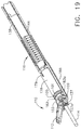
- FIG. 19 is a top perspective view of a distal end of the robotic surgical instrument with the outer shaft omitted to expose the top components, according to one aspect of this disclosure.
- FIG. 20 is a bottom perspective view of a distal end of the robotic surgical instrument with the outer shaft replaced and the clamp arm cap omitted to expose the bottom components, where the end effector is shown in an articulated configuration, according to one aspect of this disclosure.
- FIG. 21 is a bottom perspective view of a distal end of the robotic surgical instrument with the outer shaft replaced and the clamp arm cap omitted to expose the bottom components, where the end effector is shown in an articulated configuration, according to one aspect of this disclosure.
- FIG. 22 is a bottom perspective view of a distal end of the robotic surgical instrument with the outer shaft replaced and the clamp arm cap omitted to expose the bottom components, where the end effector is shown in an articulated configuration and the clamp arm is shown in a counterclockwise rotated configuration relative to FIG. 20 according to one aspect of this disclosure.
- FIG. 23 is a bottom view of a distal end of the robotic surgical instrument shown in FIG. 1 with the outer shaft replaced and the clamp arm cap omitted to expose the bottom components, according to one aspect of this disclosure.
- the present disclosure is directed to various aspects of a robotic ultrasonic surgical instrument with six degrees of freedom.
- the robotic ultrasonic surgical instrument includes a rotatable shaft, articulatable end effector, and independently rotatable distal clamp arm.
- the clamp arm is movable between open and closed positions.
- FIG. 1 illustrates a robotic ultrasonic surgical instrument 100 with six degrees of freedom, according to one aspect of this disclosure.
- the surgical instrument 100 includes a robotic interface 102 , an ultrasonic energy cord 104 , an outer shaft 108 , and an end effector 110 .
- the ultrasonic energy cord 104 is configured to electrically couple an ultrasonic energy source to an ultrasonic transducer 130 ( FIG. 3 ) by way of electrically conductive elements 128 a , 128 b ( FIG. 3 ).
- the ultrasonic transducer 130 is acoustically coupled to an ultrasonic blade 114 .
- the robotic interface 102 includes a bailout knob 106 configured to enable the clinician to manually take over operation of the robotic ultrasonic surgical instrument 100 should the robotic interface 102 become disabled.
- the robotic interface 102 is coupled to the outer shaft 108 which is coupled to end effector 110 .
- the end effector 110 includes a clamp arm 112 pivotally coupled to an ultrasonic blade 114 .
- An articulation section 116 enables the end effector 110 to articulate.
- proximal refers to a location at or near the robotic interface 102 and the term “distal” refers to a location at or near the end effector 110 or the ultrasonic blade 114 tip.
- proximal refers to the end of the robotic interface 102 where the energy cord 104 is received and the and the term “distal” refers to the end where the outer shaft 108 couples to the robotic interface 102 .
- the ultrasonic blade 114 may be configured with a straight and uniformly round distal tip so that the clamp arm 112 can rotate about the uniformly round distal tip of the ultrasonic blade 114 and clamp in any orientation of the uniformly round distal tip the ultrasonic blade 114 .
- Rotating the distal tip of the ultrasonic blade 114 distal of the articulation section 116 presents some challenges because the ultrasonic blade 114 takes up most of the space defined within the outer shaft 108 and there is little space available for additional components.
- FIG. 2 is a bottom view of the robotic interface 102 showing the rotary input motor interfaces according to one aspect of this disclosure.
- the robotic interface 102 includes four rotary inputs 120 , 122 , 124 , 126 to control various aspects of the robotic ultrasonic surgical instrument 100 .
- the rotary inputs 120 , 122 , 124 , 126 each couple to a separate electric motor controlled by a surgical robot control system.
- Functions and operations of the robotic ultrasonic surgical instrument 100 are derived from the four rotary inputs 120 , 122 , 124 , 126 .
- the rotary motions of the four rotary inputs 120 , 122 , 124 , 126 enable the robotic ultrasonic surgical instrument 100 to have six degrees of freedom.
- a shaft roll rotary input 120 is configured to couple to a shaft roll motor controlled by a surgical robot control system.
- the shaft roll motor rotates the shaft roll rotary input 120 in either direction (clockwise or counterclockwise) to rotate the outer shaft 108 .
- the robotic interface 102 converts the rotary motion of the shaft roll rotary input 120 to a rotary motion of the outer shaft 108 .
- the direction of rotation of the shaft 108 is based on the direction of rotation of the shaft roll rotary input 120 .
- the direction of rotation of the outer shaft 108 may or may not correspond to the direction of rotation of the shaft roll rotary input 120 .
- rotation of the shaft roll rotary input 120 will be referenced as clockwise (CW) and counterclockwise (CCW) relative to the bottom of the robotic interface 102 shown in FIG. 2 where the shaft roll rotary input 120 couples to the motor.
- a clamp arm closure rotary input 122 is configured to couple to a clamp arm closure motor controlled by the surgical robot control system.
- the clamp arm closure motor rotates the clamp arm closure rotary input 122 in either direction to close and open the clamp arm 112 .
- the robotic interface 102 converts the rotary motion of the clamp arm closure rotary input 122 to a motion to close or open the clamp arm 112 relative to the ultrasonic blade 114 based on the direction of rotation of the clamp arm closure rotary input 122 .
- rotation of the clamp arm closure rotary input 122 will be referenced as clockwise (CW) and counterclockwise (CCW) relative to the bottom of the robotic interface 102 shown in FIG. 2 where the clamp arm closure rotary input 122 couples to the motor.
- An articulation rotary input 124 is configured to couple to an articulation motor controlled by the surgical robot control system.
- the articulation motor rotates the articulation rotary input 124 in either direction to articulate the end effector 110 left or right at the articulation section 116 .
- the robotic interface 102 converts the rotary motion of the articulation rotary input 124 to a left/right articulation motion of the end effector 110 based on the direction of rotation of the articulation rotary input 124 .
- rotation of the articulation rotary input 124 will be referenced as clockwise (CW) and counterclockwise (CCW) relative to the bottom of the robotic interface 102 shown in FIG. 2 where the articulation rotary input 124 couples to the motor.
- the articulation section 116 can articulate over a range of ⁇ 65°, for example.
- a clamp arm roll rotary input 126 is configured to couple to a clamp arm roll motor controlled by the surgical robot control system.
- the clamp arm roll motor rotates the clamp arm roll rotary input 126 in either direction to rotate the clamp arm 112 portion of the end effector 110 about the ultrasonic blade 114 .
- the robotic interface 102 converts the rotary motion of the clamp arm roll rotary input 126 to a clockwise/counterclockwise rotation motion of the clamp arm 112 based on the direction of rotation of the clamp arm roll rotary input 126 .
- rotation of the clamp arm roll rotary input 126 will be referenced as clockwise (CW) and counterclockwise (CCW) relative to the bottom of the robotic interface 102 shown in FIG. 2 where the clamp arm roll rotary input 126 couples to the motor.
- FIGS. 3-5 illustrate the mechanisms within the robotic interface 102 that convert the rotary motion of the shaft roll rotary input 120 , the clamp arm closure rotary input 122 , the articulation rotary input 124 , and clamp arm roll rotary input 126 into shaft roll, clamp arm closure, articulation, and clamp arm roll, respectively, according to one aspect of this disclosure.
- FIG. 3 is a perspective view of the shaft roll, clamp arm closure, articulation, and clamp arm roll gear mechanism, according to one aspect of this disclosure.
- FIG. 3 illustrates a gear assembly 117 that includes a first helical gear 121 that cooperates with a second cross axis helical gear 123 to rotate the outer shaft 108 . Also shown in FIG.
- FIG. 3 are the electrically conductive elements 128 a , 128 b apply electrical energy from an ultrasonic generator to the ultrasonic transducer 130 .
- the ultrasonic transducer 130 converts the electrical energy into ultrasonic mechanical vibrations to drive the ultrasonic blade 114 .
- FIG. 4 is a perspective view of the clamp arm closure, articulation, and clamp arm roll gear mechanism, according to one aspect of this disclosure. In FIG. 4 , the gear assembly 117 and the first and second helical gears 121 , 123 are omitted to provide a view of the articulation mechanism.
- FIG. 5 is a top view of the shaft roll, clamp arm closure, articulation, and clamp arm roll gear mechanism, according to one aspect of this disclosure. The mechanisms illustrated in FIGS. 3-5 are further described hereinbelow.
- FIG. 6 is a section view of the shaft portion of the robotic ultrasonic surgical instrument 100 taken at section 6 - 6 shown in FIG. 5 , according to one aspect of this disclosure.
- the outer shaft 108 surrounds an extruded guide 165 , an overmold 148 , and an ultrasonic waveguide 161 .
- the mechanism in accordance with this disclosure employs four rods that are distributed to the sides, top, and bottom of the ultrasonic waveguide 161 .
- the extruded overmold defines longitudinal grooves or channels to receive a clamp arm closure rod 138 , left and right articulation rods 140 , 144 , and a clamp arm roll rod 142 .
- the clamp arm closure rod 138 is located above the ultrasonic waveguide 161 and is attached to a coupler 178 at connection 179 .
- the coupler 178 is rotationally fitted to a rotatable clamp arm closure tube 180 .
- the coupler 178 moves back (proximally) and forth (distally) but does not rotate.
- the rotatable clamp arm closure tube 180 can rotate in the coupler 178 . Pulling the clamp arm closure rod 138 proximally closes the clamp arm 112 and pushing on the clamp arm closure rod 138 distally opens the clamp arm 112 .
- the left and right articulation rods 140 , 144 on either side of the ultrasonic waveguide 161 are attached to the shaft 108 distal of the articulation section 116 , respectively.
- the left and right articulation rods 140 , 144 are attached to a clamp arm cap 188 at connections 170 , 172 , respectively.
- the clamp arm cap 188 is attached to the shaft 108 by tabs 183 a , 183 b that are received in notches 181 a , 181 b defined by the shaft 108 .
- the clamp arm roll rod 142 is attached to a spiral slot pin roll rod coupler 187 at connection 189 .
- the spiral slot pin roll rod coupler 187 includes a clamp arm roll pin 186 that is slidably received in a spiral slot 184 defined in a spiral slotted clamp arm roll tube 182 that is attached to the clamp arm 112 , thus enabling the clamp arm 112 to freely rotate. Moving the clamp arm roll pin 186 back (proximally) and forth (distally) in the spiral slot 184 rotates the clamp arm 112 and the rotatable clamp arm closure tube 180 relative to the shaft 108 .
- the clamp arm roll pin 186 in the spiral slot 184 mechanism provides a smooth continuous motion to the clamp arm 112 with infinite stop points. Pulling proximally on the clamp arm roll rod 142 connected to the clamp arm roll pin 186 rotates the clamp arm one direction and pushing distally on the clamp arm roll rod 142 rotates it the opposite direction.
- the clamp arm closure rod 138 and the clamp arm roll rod 142 travel along the top and bottom center of the shaft 108 . This location subjects these rods 138 , 142 to minimal length change when articulated so that the end effector 110 does not rotate and the clamp arm 112 does not close when the device articulates.
- connections 179 , 189 , 170 , 172 shown in FIG. 18 may be implemented in any suitable fashion.
- the connections 179 , 189 , 170 , 172 may be made by clevis and pin, solder, weld, threads (male or female), press fit, crimp, swage, rivet, epoxy, or any combinations thereof.
- the rods 138 , 140 , 142 , 144 can be made of any suitable metal, plastic, or composite material that includes one of a metal, plastic, or carbon material.
- the rods 138 , 140 , 142 , 144 should have a stiffness or rigidity suitable to withstand the pulling and pushing forces suitable for closing and opening the clamp arm 112 , articulating the end effector 110 in the left and right directions at the articulation section 116 , and rotating the clamp arm 112 distal of the articulation section 116 , while having enough flexibility to move around the articulated articulation section 116 in the articulated configuration.
- FIG. 10 illustrates an ultrasonic system 159 according to one aspect of this disclosure.
- the ultrasonic system 159 includes an ultrasonic transducer 130 , and ultrasonic blade 114 , and an ultrasonic transmission waveguide 161 that acoustically couples the ultrasonic transducer 130 to the ultrasonic blade 114 .
- Ultrasonic vibrations are generated by the ultrasonic transducer 130 when energized by a suitable electrical energy signal.
- the ultrasonic vibrations generated by the ultrasonic transducer 130 are transmitted to the ultrasonic blade 114 by the ultrasonic transmission waveguide 161 .
- the ultrasonic transmission waveguide 161 may be a single unitary component or may include multiple components attached together by welded, threaded, or fitted connection.
- the ultrasonic waveguide 161 includes a thin walled section 152 defining an articulation section 163 to enable the end effector 110 to articulate in left and right directions as described herein about the articulation section 163 .
- the ultrasonic vibrations transmitted to the ultrasonic blade 114 are transmitted to organic tissue at suitable energy levels and using a suitable end effector 110 , which may or may not include a clamp arm 112 , may be used to cut, dissect, elevate or cauterize tissue or to separate muscle tissue from bone.
- Ultrasonic instruments utilizing solid core technology are particularly advantageous because of the amount of ultrasonic energy that may be transmitted from the ultrasonic transducer 130 , through the waveguide 161 , to the ultrasonic blade 114 .
- the ultrasonic blade 114 tip is partially round for a certain amount of degrees and defines a cutting portion at a bottom portion of the ultrasonic blade 114 .
- ultrasonic blade 114 Activating or exciting the ultrasonic blade 114 at ultrasonic frequencies induces longitudinal vibratory movement that generates localized heat within adjacent tissue. Because of the nature of ultrasonic instruments, a particular ultrasonically actuated ultrasonic blade 114 may be designed to perform numerous functions, including, for example, cutting and coagulation. These surgical effects may be enhanced by incorporating the clamp arm 112 to apply pressure to the tissue during the procedure. The clamp arm 112 may include a lubricious pad to further enhance the surgical effects. Ultrasonic vibration is induced in the ultrasonic blade 114 by electrically exciting the ultrasonic transducer 130 , for example. The transducer 130 may be constructed of one or more piezoelectric or magnetostrictive elements in the instrument hand piece.
- Vibrations generated by the transducer 130 are transmitted to the ultrasonic blade 114 via the ultrasonic waveguide 161 extending from the transducer 130 to the ultrasonic blade 114 located in the end effector 110 .
- the waveguide 161 and the ultrasonic blade 114 are designed to resonate at the same frequency as the transducer 130 . Therefore, when the ultrasonic blade 114 is attached to the transducer 130 , the overall system frequency is the same as the vibratory frequency of the transducer 130 itself.
- ⁇ the radian frequency which equals 2 ⁇ times the cyclic frequency, f;
- A the zero-to-peak amplitude
- the longitudinal excursion of the distal tip of the ultrasonic blade 114 is defined as the peak-to-peak (p-t-p) amplitude, which is just twice the amplitude of the sine wave or 2 A.
- the ultrasonic blade 114 owing to the longitudinal excursion, can cut and/or coagulate tissue.
- the present disclosure provides a mechanism to rotate the outer shaft 108 of the robotic ultrasonic surgical instrument 100 in a clockwise or counterclockwise direction.
- the shaft roll rotary input 120 includes a drive gear 115 which is coupled to a gear assembly 117 .
- the gear assembly 117 includes a driven gear 119 which rotates a shaft 113 .
- a first helical gear 121 is attached to the shaft 113 and rotates with the driven gear 119 .
- the first helical gear 121 drives a second cross axis helical gear 123 attached about the outer shaft 108 to rotate the outer shaft 108 .
- the direction of rotation of the outer shaft 108 depends on the direction of rotation of the shaft roll rotary input 120 .
- a CW rotation of the shaft roll rotary input 120 as described in FIG. 2 produces a corresponding CW rotation of the outer shaft 108
- a CCW rotation of the shaft roll rotary input 120 as described in FIG. 2 produces a corresponding CCW rotation of the outer shaft 108 .
- the present disclosure provides a mechanism to open and close the clamp arm 112 .
- the clamp arm closure rotary input 122 includes a drive gear 125 coupled to a gear assembly 127 .
- the gear assembly 127 includes a pinion gear 129 to drive a clamp arm closure rack gear 166 .
- the clamp arm closure rack gear 166 includes a rack 136 that defines a semiannular groove 133 to receive a clamp arm closure ring 158 .
- the clamp arm closure ring 158 is attached to a closure tube section 135 .
- the closure tube section 135 is attached to a clamp arm closure rod 138 at a connection 151 .
- the connection 151 may be implemented in any suitable fashion, such as, for example, clevis and pin, solder, weld, threads (male or female), press fit, crimp, swage, rivet, epoxy, or any combinations thereof.
- the clamp arm closure rod 138 is attached to the clamp arm closure coupler 178 that is rotationally fitted to the rotatable clamp arm closure tube 180 .
- the clamp arm closure coupler 178 cooperates with a rotatable clamp arm closure tube 180 to open and close the clamp arm 112 .
- the rotatable clamp arm closure tube 180 includes a closure link 137 that defines slots 155 a , 155 b on opposite sides of the closure link 137 .
- the slots 155 a , 155 b engage corresponding pins 157 a , 157 b formed on the clamp arm 112 .
- the clamp arm closure coupler 178 moves back and forth but does not rotate.
- the rotatable clamp arm closure tube 180 can rotate in the clamp arm closure coupler 178 . Applying a pulling force on the clamp arm closure rod 138 in the proximal direction closes the clamp arm 112 and applying a pushing force on the clamp arm closure rod 138 in a distal direction opens the clamp arm 112 .
- the clamp arm closure rotary input 122 is rotated in a CW direction as described in FIG. 2 .
- the drive gear 125 drives the pinion gear 129 causing the clamp arm closure rack gear 166 and the clamp arm closure ring 158 to translate in the proximal direction P. Accordingly, the clamp arm closure ring 158 pulls the closure tube section 135 and the clamp arm closure rod 138 in the proximal direction P.
- the rotatable clamp arm closure tube 180 is pulled in the proximal direction P and the clamp arm pins 157 a , 157 b engage the corresponding slots 155 a , 155 b defined by the closure link 137 to rotate the clamp arm 112 from the open position shown in FIG. 11 to the closed position shown in FIG. 12 .
- the clamp arm closure rotary input 122 is rotated in a CCW direction as described in FIG. 2 .
- the drive gear 125 drives the pinion gear 129 causing the clamp arm closure rack gear 166 and the clamp arm closure ring 158 to translate in the distal direction D. Accordingly, the clamp arm closure ring 158 pushes the closure tube section 135 and the clamp arm closure rod 138 in the distal direction D.
- the rotatable clamp arm closure tube 180 is pushed in the distal direction D and once again the clamp arm pins 157 a , 157 b engage the corresponding slots 155 a , 155 b defined by the closure link 137 to rotate the clamp arm 112 from the closed position shown in FIG. 12 to the open position shown in FIG. 11 .
- the gear assembly 127 includes another gear coupled to the shaft of the bailout knob 106 .
- the gear 131 rotates with the shaft 150 .
- the clamp arm 112 can be closed or opened manually by rotating the bailout knob 106 CW or CCW, respectively.
- the present disclosure provides a mechanism to articulate the end effector 110 left or right at the articulation section 116 .
- Left and right articulation rods 140 , 144 positioned on either side of the ultrasonic waveguide 161 are attached to the shaft 108 distal of the articulation section 116 . Pulling one articulation rod 140 , 144 and pushing the other articulation rod 144 , 140 articulates the end effector 110 , and thus articulates the ultrasonic blade 114 .
- the articulation rotary input 124 includes a pinion gear 141 that engages first and second articulation rack gears 160 a , 160 b .
- the first articulation rack gear 160 a includes a first rack 132 a that defines a first semiannular groove 139 a to receive a first ring 154 a .
- the first ring 154 a is attached to a left articulation tube section 143 a which is attached to the left articulation rod 140 at a connection 147 a .
- the left articulation rod 140 is attached to a left articulation connection 170 at a distal end of the articulation section 116 (see FIG. 17 ) and a proximal end of the clamp arm cap 188 (see FIG. 18 ).
- the second articulation rack gear 160 b includes a second rack 132 b that defines a second semiannular groove 139 b to receive a second ring 154 b .
- the second ring 154 b is attached to a right articulation tube section 143 b which is attached to the left articulation rod 140 at a connection similar to connection 147 a .
- the right articulation rod 144 is attached to a right articulation connection 172 at a distal end of the articulation section 116 (see FIG. 17 ) and a proximal end of the clamp arm cap 188 (see FIG. 18 ).
- the connection 147 a may be implemented in any suitable fashion, such as, for example, clevis and pin, solder, weld, threads (male or female), press fit, crimp, swage, rivet, epoxy, or any combinations thereof.
- An outer articulation tube 174 facilitates articulation at the articulation section 116 .
- the articulation rotary input 124 is rotated CW as described in FIG. 2 .
- the pinion gear 141 simultaneously drives the first articulation rack gear 160 a in the proximal direction P and drives the second articulation rack gear 162 b in the distal direction D.
- the first and second racks 132 a , 132 b are formed integrally, or are fixedly attached to move in unison, with the first and second articulation rack gears 160 a , 160 b .
- the first and second racks 132 a , 132 b move in the same direction as the first and second articulation rack gears 160 a , 160 b , respectively.
- the first and second rings 154 a , 154 b also move in the same direction as the first and second racks 132 a , 132 b , respectively. Accordingly, the left articulation tube section 143 a pulls the left articulation rod 140 in the proximal direction P and the right articulation tube section 143 b pushes the left articulation rod 140 in the distal direction D to articulate the end effector 110 to the left as shown in FIG. 13 .
- the articulation rotary input 124 is rotated CCW as described in FIG. 2 .
- the pinion gear 141 simultaneously drives the first articulation rack gear 160 a in the distal direction D and drives the second articulation rack gear 162 b in the proximal direction P.
- the first and second rings 154 a , 154 b move in the same direction as the first and second racks 132 a , 132 b , respectively.
- the left articulation tube section 143 a pushes the left articulation rod 140 in the distal D direction P and the right articulation tube section 143 b pulls the right articulation rod 144 in the proximal direction P to articulate the end effector 110 to the right as shown in FIG. 14 .
- the present disclosure provides mechanisms for rotating the distal clamp arm 112 clockwise or counterclockwise independently of the outer shaft 108 .
- the clamp arm roll rotary input 126 includes a pinion gear 167 that engages a clamp arm roll rack gear 164 .
- the clamp arm roll rack gear 164 includes a rack 134 that defines a semiannular groove 169 to receive a ring 156 .
- the ring 156 is attached to a clamp arm roll tube section 145 which is attached to the clamp arm roll rod 142 at a connection 153 .
- the connection 153 may be implemented in any suitable fashion, such as, for example, clevis and pin, solder, weld, threads (male or female), press fit, crimp, swage, rivet, epoxy, or any combinations thereof.
- FIG. 18 is an exploded view of a distal portion of the robotic ultrasonic surgical instrument 100 comprising a spiral slotted mechanism, according to one aspect of this disclosure.
- the clamp arm roll rod 142 connects to a pin that is coupled to a rotating clamp arm through a spiral slot. Moving the pin back and forth in the spiral slot rotates the clamp arm and clamp arm pull relative to the shaft.
- the pin in the spiral slot mechanism gives smooth motion to the clamp arm with infinite stop points. Pulling on the rod connected to the pin rotates the clamp arm one direction and pushing rotates it the opposite direction.
- the clamp arm closure and distal rotation rods travel along the top and bottom center of the shaft. This location subjects the rods to minimal length change when articulated so that the end effector does not rotate and the clamp arm does not close when the device articulates.
- the end effector 110 includes a spiral slotted clamp arm roll tube 182 and the clamp arm roll rod 142 is attached to a clamp arm roll pin 186 .
- the distal clamp arm 112 can be rotated clockwise or counterclockwise independently of rotating or articulating the outer shaft 108 or opening or closing the clamp arm 112 .
- clamp arm roll rotary input 126 is rotated CW as described in FIG. 2 .
- the pinion gear 167 engages the clamp arm roll rack gear 164 to pull the clamp arm roll tube section 145 and the clamp arm roll rod 142 in the proximal direction P as shown in FIG. 15 .
- Clockwise distal rotation of the clamp arm 112 may be implemented by the spiral slotted clamp arm roll tube 182 .
- the clamp arm roll rotary input 126 is rotated CCW as described in FIG. 2 .
- the pinion gear 167 engages the clamp arm roll rack gear 164 to push the clamp arm roll tube section 145 and the clamp arm roll rod 142 in the distal direction D as shown in FIG. 16 .
- Counterclockwise distal rotation of the clamp arm 112 also may be implemented by the spiral slotted clamp arm roll tube 182 .
- the spiral slotted clamp arm roll tube 182 aspects of the robotic ultrasonic surgical instrument 100 will be described hereinbelow.
- the spiral slotted clamp arm roll tube 182 includes a clamp arm 112 with pins 157 a , 157 b that engage slots 155 a , 155 b defined by the closure link 137 .
- the spiral slotted clamp arm roll tube 182 includes a mounting tab 111 defining a hole to receive a pin 109 to rotatably mount the clamp arm 112 to the spiral slotted clamp arm roll tube 182 .
- the spiral slotted clamp arm roll tube 182 is inserted over the rotatable clamp arm closure tube 180 and can freely rotate about the rotatable clamp arm closure tube 180 .
- the rotatable clamp arm closure tube 180 includes a flange 185 that is rotatably received in a semiannular groove 191 defined at the proximal end of the clamp arm closure coupler 178 as shown in FIGS. 20-23 .
- the clamp arm closure coupler 178 can thus actuate the rotatable clamp arm closure tube 180 to close and open the clamp arm 112 while the rotatable clamp arm closure tube 180 can readily rotate within the semiannular groove 191 .
- the clamp arm closure coupler 178 is positioned over the spiral slotted clamp arm roll tube 182 .
- the clamp arm closure coupler 178 is attached to the clamp arm closure rod 138 at a connection 179 .
- a spiral slot pin roll rod coupler 187 includes a clamp arm roll pin 186 attached thereto and a connection 189 to attach the clamp arm roll rod 142 thereto.
- the clamp arm roll pin 186 is slidably received in a spiral slot 184 defined in the spiral slotted clamp arm roll tube 182 .
- the spiral slot pin roll rod coupler 187 is slidably received in a longitudinal slot 107 defined at the bottom of a clamp arm cap 188 .
- the spiral slotted clamp arm roll tube 182 is positioned in the clamp arm cap 188 which is attached to left and right articulation rods 140 , 144 that are attached to connections 170 , 172 , respectively.
- the clamp arm cap 188 also includes semiannular surface 193 and a semiannular edge 195 to receive corresponding flanges 101 , 103 located at the distal end of the spiral slotted clamp arm roll tube 182 .
- a bearing surface 105 defined between the flanges 101 , 103 rotatably contacts a bearing 197 defined at a distal end of the clamp arm cap 188 between the semiannular surface 193 and the semiannular edge 195 .
- Tabs 183 a , 183 b at a distal end of the clamp arm cap 188 are received in corresponding notches 181 a , 181 b defined at a distal end of the outer shaft 108 .
- the ultrasonic blade 114 is inserted through rotatable clamp arm closure tube 180 and the outer shaft 108 is positioned over the clamp arm cap 188 and the clamp arm closure coupler 178 .
- FIG. 19-23 illustrate an end effector 110 that includes a spiral slotted clamp arm roll tube 182 configured to operate with the robotic ultrasonic surgical instrument 100 according to one aspect of this disclosure.
- FIG. 19 is a top perspective view of a distal end of the robotic surgical instrument 100 with the outer shaft 108 omitted to expose the top components, according to one aspect of this disclosure.
- the clamp arm 112 is in an open position and in a rotational home reference position.
- the articulation section 116 is in an unarticulated configuration.
- FIG. 20 is a bottom perspective view of a distal end of the robotic surgical instrument 100 with the outer shaft 108 replaced and the clamp arm cap 188 omitted to expose the bottom components, according to one aspect of this disclosure.
- FIG. 20 illustrates a view of the spiral slotted clamp arm roll tube 182 configuration.
- the clamp arm 112 is in an open position and in a rotational home reference position as shown in FIG. 19 .
- the articulation section 116 is in an unarticulated configuration.
- FIG. 23 is a bottom view of a distal end of the robotic surgical instrument 100 with the outer shaft 108 replaced and the clamp arm cap 188 omitted to expose the bottom components, according to one aspect of this disclosure.
- the articulation section 116 is in an unarticulated configuration.
- the spiral slotted clamp arm roll tube 182 is located between a distal portion of the outer shaft 108 and the clamp arm cap 188 .
- the slotted clamp arm roll tube 182 is rotatably positioned over the rotatable clamp arm closure tube 180 .
- the clamp arm closure coupler 178 is slidably attached to the rotatable clamp arm closure tube 180 .
- the flange 185 of the rotatable clamp arm closure tube 180 is rotatably positioned within the semiannular groove 191 defined by the clamp arm closure coupler 178 .
- the rotatable clamp arm closure tube 180 and the spiral slotted clamp arm roll tube 182 are free to rotate.
- the clamp arm closure coupler 178 , the spiral slot pin roll rod coupler 187 , and the clamp arm roll pin 186 are constrained to move axially along the longitudinal axis.
- the flanges 101 , 103 and the bearing surface 105 on the distal end of the spiral slotted clamp arm roll tube 182 support the spiral slotted clamp arm roll tube 182 .
- a mounting tab 111 is provided on the distal end of the distal flange 103 to attach the clamp arm 112 with a pin 109 .
- the clamp arm 112 is pivotally rotatable about the pin 109 between open and closed positions.
- FIGS. 21 and 22 are bottom perspective view of a distal end of the robotic surgical instrument 100 with the outer shaft 108 replaced and the clamp arm cap 188 omitted to expose the bottom components, according to one aspect of this disclosure.
- the articulation section 116 is in an articulated configuration and thus the end effector 110 also is in the articulated configuration.
- the spiral slot pin roll rod coupler 187 and clamp arm roll pin 186 are located in a first position along the spiral slot 184 and the clamp arm 112 is rotated in a first rotational position.
- the clamp arm 112 is rotated relative to the position of the clamp arm 112 shown in FIG. 20 , where the end effector 110 is shown in an articulated configuration.
- the spiral slot pin roll rod coupler 187 and clamp arm roll pin 186 have been pushed distally to a second position along the spiral slot 184 and the clamp arm 112 is shown rotated counterclockwise in a second rotational position while the end effector 110 remains in the articulated configuration.
- the spiral slot pin roll rod coupler 187 and clamp arm roll pin 186 pulled back proximally to a more proximal position along the spiral slot 184 and the clamp arm 112 .
- the clamp arm 112 is freely rotatable about the ultrasonic blade 114 independently of the outer shaft 108 .
- the clamp arm roll rod 142 is pulled proximally.
- the clamp arm roll pin 186 slidably engages the spiral slot 184 to turn the spiral slotted clamp arm roll tube 182 in a clockwise direction.
- the clamp arm roll rod 142 is pushed distally.
- the clamp arm roll pin 186 slidably engages the spiral slot 184 to turn the spiral slotted clamp arm roll tube 182 in a counterclockwise direction.
- the clamp arm 112 can be closed or opened by the clamp arm closure coupler 178 in cooperation with the rotatable clamp arm closure tube 180 .
- the ultrasonic blade 114 and waveguide 161 do not rotate.
- the position of the articulation section 116 should be maintained relative to the thin walled section 152 section of the ultrasonic waveguide 161 to enable the end effector 110 to articulate.
- Advantages of the spiral slotted clamp arm 182 configuration to rotate the distal clamp arm 112 includes its simple design and provides continuous motion with few parts and has infinite stop points in its range.
- the devices disclosed herein can be designed to be disposed of after a single use, or they can be designed to be used multiple times. In either case, however, the device can be reconditioned for reuse after at least one use. Reconditioning can include any combination of the steps of disassembly of the device, followed by cleaning or replacement of particular pieces, and subsequent reassembly. In particular, the device can be disassembled, and any number of the particular pieces or parts of the device can be selectively replaced or removed in any combination. Upon cleaning and/or replacement of particular parts, the device can be reassembled for subsequent use either at a reconditioning facility, or by a surgical team immediately prior to a surgical procedure.
- reconditioning of a device can utilize a variety of techniques for disassembly, cleaning/replacement, and reassembly. Use of such techniques, and the resulting reconditioned device, are all within the scope of the present application.
- a surgical instrument comprising: a rotatable shaft comprising an articulation section; an ultrasonic waveguide disposed within the shaft, wherein the ultrasonic waveguide is configured to articulate at the articulation section; and a rotatable clamp arm located distal of the articulation section of the rotatable shaft, wherein the rotatable clamp arm is configured to rotate independently of the rotatable shaft distal of the articulation section.
- Example 3 The surgical instrument of one or more of Example 1 through Example 2, wherein the ultrasonic waveguide comprises an ultrasonic blade tip that is partially round and defines a cutting tip on a bottom portion.
- Example 4 The surgical instrument of one or more of Example 1 through Example 3, further comprising a spiral slotted clamp arm roll tube coupled to the rotatable clamp arm, wherein the a spiral slotted clamp arm roll tube defines a spiral slot configured to slidably receive a pin, wherein proximal and distal translation of the pin causes the spiral slotted clamp arm roll tube and the clamp arm to rotate about an ultrasonic blade portion of the ultrasonic waveguide independently of the rotatable shaft.
- the surgical instrument of claim Example 4 further comprising: a clamp arm roll rod; a spiral slot pin roll rod coupler attached to the clamp arm roll rod at a connection; and a pin attached to the spiral slot pin roll rod coupler.
- Example 6 The surgical instrument of one or more of Example 4 through Example 6, further comprising a rotatable closure tube located within the spiral slotted clamp arm roll tube, the rotatable closure tube comprising a closure link at a distal end of the rotatable closure tube, wherein the closure link defines slots to receive pins defined by the clamp arm.
- Example 7 The surgical instrument of Example 6, further comprising: a clamp arm closure rod; and a coupler attached to the clamp arm closure rod at a connection; wherein the rotatable closure tube defines a flange at a proximal end; and wherein the coupler defines a semiannular groove configured to rotatably receive the flange.
- Example 8 The surgical instrument of one or more of Example 4 through Example 7, further comprising: first and second articulation rods; and a clamp arm cap configured to rotatably receive the spiral slotted clamp arm roll tube, wherein the first and second articulation rods are attached to a proximal end of the clamp arm cap at first and second connections.
Landscapes
- Health & Medical Sciences (AREA)
- Surgery (AREA)
- Life Sciences & Earth Sciences (AREA)
- Engineering & Computer Science (AREA)
- Heart & Thoracic Surgery (AREA)
- Nuclear Medicine, Radiotherapy & Molecular Imaging (AREA)
- Biomedical Technology (AREA)
- Medical Informatics (AREA)
- Molecular Biology (AREA)
- Animal Behavior & Ethology (AREA)
- General Health & Medical Sciences (AREA)
- Public Health (AREA)
- Veterinary Medicine (AREA)
- Mechanical Engineering (AREA)
- Dentistry (AREA)
- Robotics (AREA)
- Surgical Instruments (AREA)
Abstract
Description
d=A sin(ωt)
where:
Claims (9)
Priority Applications (8)
| Application Number | Priority Date | Filing Date | Title |
|---|---|---|---|
| US15/994,755 US11033293B2 (en) | 2017-07-19 | 2018-05-31 | Ultrasonic transducer to blade acoustic coupling, connections, and configurations |
| CN201880048012.8A CN110958861B (en) | 2017-07-19 | 2018-07-16 | Surgical devices and systems having a rotary end effector assembly with ultrasonic blade |
| EP18749963.7A EP3654856B1 (en) | 2017-07-19 | 2018-07-16 | Surgical devices and systems with rotating end effector assemblies having an ultrasonic blade |
| KR1020207004539A KR102645918B1 (en) | 2017-07-19 | 2018-07-16 | Surgical devices and systems having rotating end effector assemblies with ultrasonic blades |
| JP2020502473A JP7237923B2 (en) | 2017-07-19 | 2018-07-16 | Surgical device and system with rotating end effector assembly with ultrasonic blade |
| PCT/US2018/042295 WO2019018289A1 (en) | 2017-07-19 | 2018-07-16 | Surgical devices and systems with rotating end effector assemblies having an ultrasonic blade |
| BR112020000933-4A BR112020000933B1 (en) | 2017-07-19 | 2018-07-16 | SURGICAL DEVICE AND ROBOTIC SURGICAL SYSTEM |
| US17/329,747 US20210346050A1 (en) | 2017-07-19 | 2021-05-25 | Ultrasonic transducer to blade acoustic coupling, connections, and configurations |
Applications Claiming Priority (2)
| Application Number | Priority Date | Filing Date | Title |
|---|---|---|---|
| US15/654,428 US20190021752A1 (en) | 2017-07-19 | 2017-07-19 | Ultrasonic transducer to blade acoustic coupling, connections, and configurations |
| US15/994,755 US11033293B2 (en) | 2017-07-19 | 2018-05-31 | Ultrasonic transducer to blade acoustic coupling, connections, and configurations |
Related Parent Applications (1)
| Application Number | Title | Priority Date | Filing Date |
|---|---|---|---|
| US15/654,428 Continuation-In-Part US20190021752A1 (en) | 2017-07-19 | 2017-07-19 | Ultrasonic transducer to blade acoustic coupling, connections, and configurations |
Related Child Applications (1)
| Application Number | Title | Priority Date | Filing Date |
|---|---|---|---|
| US17/329,747 Continuation US20210346050A1 (en) | 2017-07-19 | 2021-05-25 | Ultrasonic transducer to blade acoustic coupling, connections, and configurations |
Publications (2)
| Publication Number | Publication Date |
|---|---|
| US20190021756A1 US20190021756A1 (en) | 2019-01-24 |
| US11033293B2 true US11033293B2 (en) | 2021-06-15 |
Family
ID=65014615
Family Applications (2)
| Application Number | Title | Priority Date | Filing Date |
|---|---|---|---|
| US15/994,755 Active 2038-03-16 US11033293B2 (en) | 2017-07-19 | 2018-05-31 | Ultrasonic transducer to blade acoustic coupling, connections, and configurations |
| US17/329,747 Pending US20210346050A1 (en) | 2017-07-19 | 2021-05-25 | Ultrasonic transducer to blade acoustic coupling, connections, and configurations |
Family Applications After (1)
| Application Number | Title | Priority Date | Filing Date |
|---|---|---|---|
| US17/329,747 Pending US20210346050A1 (en) | 2017-07-19 | 2021-05-25 | Ultrasonic transducer to blade acoustic coupling, connections, and configurations |
Country Status (1)
| Country | Link |
|---|---|
| US (2) | US11033293B2 (en) |
Families Citing this family (5)
| Publication number | Priority date | Publication date | Assignee | Title |
|---|---|---|---|---|
| US10582945B2 (en) | 2018-03-20 | 2020-03-10 | Ethicon Llc | Surgical devices and systems with rotating end effector assemblies having an ultrasonic blade |
| US10925630B2 (en) | 2018-06-19 | 2021-02-23 | Ethicon Llc | Surgical devices and systems with rotating end effector assemblies having an ultrasonic blade |
| US11766275B2 (en) * | 2020-05-18 | 2023-09-26 | Covidien Lp | Articulating ultrasonic surgical instruments and systems |
| US11890030B2 (en) * | 2020-10-22 | 2024-02-06 | Auris Health, Inc. | Surgical instrument with an articulatable shaft assembly and dual end effector roll |
| EP4299031A3 (en) * | 2020-10-22 | 2024-03-13 | Cilag GmbH International | Surgical instrument with an articulatable shaft assembly and dual end effector roll |
Citations (46)
| Publication number | Priority date | Publication date | Assignee | Title |
|---|---|---|---|---|
| US5792135A (en) | 1996-05-20 | 1998-08-11 | Intuitive Surgical, Inc. | Articulated surgical instrument for performing minimally invasive surgery with enhanced dexterity and sensitivity |
| US5893835A (en) | 1997-10-10 | 1999-04-13 | Ethicon Endo-Surgery, Inc. | Ultrasonic clamp coagulator apparatus having dual rotational positioning |
| US5944737A (en) | 1997-10-10 | 1999-08-31 | Ethicon Endo-Surgery, Inc. | Ultrasonic clamp coagulator apparatus having improved waveguide support member |
| US6056735A (en) | 1996-04-04 | 2000-05-02 | Olympus Optical Co., Ltd. | Ultrasound treatment system |
| US6132368A (en) | 1996-12-12 | 2000-10-17 | Intuitive Surgical, Inc. | Multi-component telepresence system and method |
| US6231565B1 (en) | 1997-06-18 | 2001-05-15 | United States Surgical Corporation | Robotic arm DLUs for performing surgical tasks |
| US6364888B1 (en) | 1996-09-09 | 2002-04-02 | Intuitive Surgical, Inc. | Alignment of master and slave in a minimally invasive surgical apparatus |
| WO2003082133A1 (en) | 2002-03-28 | 2003-10-09 | Michael John Radley Young | Improved surgical tool mechanism |
| US6669690B1 (en) | 1995-04-06 | 2003-12-30 | Olympus Optical Co., Ltd. | Ultrasound treatment system |
| US6783524B2 (en) | 2001-04-19 | 2004-08-31 | Intuitive Surgical, Inc. | Robotic surgical tool with ultrasound cauterizing and cutting instrument |
| US20060058825A1 (en) | 2004-09-10 | 2006-03-16 | Aloka Co., Ltd. | Ultrasonic surgical apparatus |
| EP1698289A2 (en) | 1996-10-04 | 2006-09-06 | United States Surgical Corporation | Instrument for cutting tissue |
| US7524320B2 (en) | 1998-12-08 | 2009-04-28 | Intuitive Surgical, Inc. | Mechanical actuator interface system for robotic surgical tools |
| US7621930B2 (en) | 2006-01-20 | 2009-11-24 | Ethicon Endo-Surgery, Inc. | Ultrasound medical instrument having a medical ultrasonic blade |
| US7691098B2 (en) | 2001-06-29 | 2010-04-06 | Intuitive Surgical, Inc. | Platform link wrist mechanism |
| US7806891B2 (en) | 1998-11-20 | 2010-10-05 | Intuitive Surgical Operations, Inc. | Repositioning and reorientation of master/slave relationship in minimally invasive telesurgery |
| US7824401B2 (en) | 2004-10-08 | 2010-11-02 | Intuitive Surgical Operations, Inc. | Robotic tool with wristed monopolar electrosurgical end effectors |
| US20120101495A1 (en) * | 2010-10-23 | 2012-04-26 | Sra Developments Limited | Ergonomic handpiece for laparoscopic and open surgery |
| US20120292367A1 (en) | 2006-01-31 | 2012-11-22 | Ethicon Endo-Surgery, Inc. | Robotically-controlled end effector |
| WO2014151621A1 (en) | 2013-03-15 | 2014-09-25 | Sri International | Hyperdexterous surgical system |
| WO2014151952A1 (en) | 2013-03-14 | 2014-09-25 | Sri International | Compact robotic wrist |
| WO2014148898A1 (en) | 2013-03-21 | 2014-09-25 | Technische Universiteit Delft | Surgical device, in particular for minimally invasive surgery |
| US20150012021A1 (en) | 2013-07-04 | 2015-01-08 | Empire Technology Development Llc | Freely-rotating minimally-invasive medical tool |
| US20150080924A1 (en) * | 2013-09-17 | 2015-03-19 | Ethicon Endo-Surgery, Inc. | Articulation features for ultrasonic surgical instrument |
| US8986302B2 (en) | 2009-10-09 | 2015-03-24 | Ethicon Endo-Surgery, Inc. | Surgical generator for ultrasonic and electrosurgical devices |
| US20150164531A1 (en) * | 2013-12-17 | 2015-06-18 | Ethicon Endo-Surgery, Inc. | Rotation features for ultrasonic surgical instrument |
| US20150209059A1 (en) | 2014-01-28 | 2015-07-30 | Ethicon Endo-Surgery, Inc. | Methods and devices for controlling motorized surgical devices |
| US9095367B2 (en) | 2012-10-22 | 2015-08-04 | Ethicon Endo-Surgery, Inc. | Flexible harmonic waveguides/blades for surgical instruments |
| US20150320437A1 (en) | 2014-04-22 | 2015-11-12 | Ethicon Endo-Surgery, Inc. | Method of operating an articulating ultrasonic surgical instrument |
| US9351754B2 (en) | 2012-06-29 | 2016-05-31 | Ethicon Endo-Surgery, Llc | Ultrasonic surgical instruments with distally positioned jaw assemblies |
| US9351753B2 (en) | 2012-01-30 | 2016-05-31 | Covidien Lp | Ultrasonic medical instrument with a curved waveguide |
| US9408622B2 (en) | 2012-06-29 | 2016-08-09 | Ethicon Endo-Surgery, Llc | Surgical instruments with articulating shafts |
| US9445816B2 (en) | 2012-12-17 | 2016-09-20 | Ethicon Endo-Surgery, Llc | Circular stapler with selectable motorized and manual control |
| US20160296250A1 (en) | 2012-06-29 | 2016-10-13 | Ethicon Endo-Surgery, Llc | Surgical instruments with articulating shafts |
| US20160296268A1 (en) | 2015-04-07 | 2016-10-13 | Ethicon Endo-Surgery, Llc | Articulating radio frequency (rf) tissue seal with articulating state sensing |
| WO2016168184A1 (en) | 2015-04-13 | 2016-10-20 | Ethicon Endo-Surgery, Llc | Ultrasonic surgical instrument with removable handle assembly |
| US20160302819A1 (en) | 2015-04-16 | 2016-10-20 | Ethicon Endo-Surgery, Llc | Ultrasonic surgical instrument with articulating end effector having a curved blade |
| US9585658B2 (en) | 2007-06-04 | 2017-03-07 | Ethicon Endo-Surgery, Llc | Stapling systems |
| US20170095295A1 (en) | 2015-10-02 | 2017-04-06 | Ethicon Endo-Surgery, Llc | System and method of converting user input into motion of a surgical instrument via a robotic surgical system |
| US20170196637A1 (en) | 2012-06-28 | 2017-07-13 | Ethicon Llc | Multi-functional powered surgical device with external dissection features |
| US20170202571A1 (en) | 2016-01-15 | 2017-07-20 | Ethicon Endo-Surgery, Llc | Modular battery powered handheld surgical instrument with reusable asymmetric handle housing |
| US20170202609A1 (en) | 2016-01-15 | 2017-07-20 | Ethicon Endo-Surgery, Llc | Modular battery powered handheld surgical instrument with curved end effectors having asymmetric engagement between jaw and blade |
| US20180000543A1 (en) | 2016-07-01 | 2018-01-04 | Ethicon Endo-Surgery, Llc | Methods, Systems, and Devices for Initializing a Surgical Tool |
| US20180049813A1 (en) | 2016-08-16 | 2018-02-22 | Ethicon Endo-Surgery, Llc | Methods, systems, and devices for controlling a motor of a robotic surgical system |
| US20190021752A1 (en) | 2017-07-19 | 2019-01-24 | Ethicon Llc | Ultrasonic transducer to blade acoustic coupling, connections, and configurations |
| US20190290318A1 (en) | 2018-03-20 | 2019-09-26 | Ethicon Llc | Surgical devices and systems with rotating end effector assemblies having an ultrasonic blade |
Family Cites Families (2)
| Publication number | Priority date | Publication date | Assignee | Title |
|---|---|---|---|---|
| US11457945B2 (en) * | 2019-08-30 | 2022-10-04 | Cilag Gmbh International | Ultrasonic blade and clamp arm alignment features |
| US20210353325A1 (en) * | 2020-05-18 | 2021-11-18 | Covidien Lp | Articulating ultrasonic surgical instruments and systems |
-
2018
- 2018-05-31 US US15/994,755 patent/US11033293B2/en active Active
-
2021
- 2021-05-25 US US17/329,747 patent/US20210346050A1/en active Pending
Patent Citations (57)
| Publication number | Priority date | Publication date | Assignee | Title |
|---|---|---|---|---|
| US6669690B1 (en) | 1995-04-06 | 2003-12-30 | Olympus Optical Co., Ltd. | Ultrasound treatment system |
| US8574228B2 (en) | 1995-04-06 | 2013-11-05 | Olympus Corporation | Ultrasound treatment system |
| US8672935B2 (en) | 1995-04-06 | 2014-03-18 | Olympus Corporation | Ultrasound treatment system |
| US7780659B2 (en) | 1995-04-06 | 2010-08-24 | Olympus Corporation | Ultrasound treatment system |
| US6056735A (en) | 1996-04-04 | 2000-05-02 | Olympus Optical Co., Ltd. | Ultrasound treatment system |
| US5792135A (en) | 1996-05-20 | 1998-08-11 | Intuitive Surgical, Inc. | Articulated surgical instrument for performing minimally invasive surgery with enhanced dexterity and sensitivity |
| US6364888B1 (en) | 1996-09-09 | 2002-04-02 | Intuitive Surgical, Inc. | Alignment of master and slave in a minimally invasive surgical apparatus |
| EP1698289A2 (en) | 1996-10-04 | 2006-09-06 | United States Surgical Corporation | Instrument for cutting tissue |
| US6132368A (en) | 1996-12-12 | 2000-10-17 | Intuitive Surgical, Inc. | Multi-component telepresence system and method |
| US6231565B1 (en) | 1997-06-18 | 2001-05-15 | United States Surgical Corporation | Robotic arm DLUs for performing surgical tasks |
| US5944737A (en) | 1997-10-10 | 1999-08-31 | Ethicon Endo-Surgery, Inc. | Ultrasonic clamp coagulator apparatus having improved waveguide support member |
| US5893835A (en) | 1997-10-10 | 1999-04-13 | Ethicon Endo-Surgery, Inc. | Ultrasonic clamp coagulator apparatus having dual rotational positioning |
| US7806891B2 (en) | 1998-11-20 | 2010-10-05 | Intuitive Surgical Operations, Inc. | Repositioning and reorientation of master/slave relationship in minimally invasive telesurgery |
| US7524320B2 (en) | 1998-12-08 | 2009-04-28 | Intuitive Surgical, Inc. | Mechanical actuator interface system for robotic surgical tools |
| US6783524B2 (en) | 2001-04-19 | 2004-08-31 | Intuitive Surgical, Inc. | Robotic surgical tool with ultrasound cauterizing and cutting instrument |
| US7691098B2 (en) | 2001-06-29 | 2010-04-06 | Intuitive Surgical, Inc. | Platform link wrist mechanism |
| WO2003082133A1 (en) | 2002-03-28 | 2003-10-09 | Michael John Radley Young | Improved surgical tool mechanism |
| US7520865B2 (en) | 2002-03-28 | 2009-04-21 | Michael John Radley Young | Surgical tool mechanism |
| US20060058825A1 (en) | 2004-09-10 | 2006-03-16 | Aloka Co., Ltd. | Ultrasonic surgical apparatus |
| US7824401B2 (en) | 2004-10-08 | 2010-11-02 | Intuitive Surgical Operations, Inc. | Robotic tool with wristed monopolar electrosurgical end effectors |
| US7621930B2 (en) | 2006-01-20 | 2009-11-24 | Ethicon Endo-Surgery, Inc. | Ultrasound medical instrument having a medical ultrasonic blade |
| US20120292367A1 (en) | 2006-01-31 | 2012-11-22 | Ethicon Endo-Surgery, Inc. | Robotically-controlled end effector |
| US9585658B2 (en) | 2007-06-04 | 2017-03-07 | Ethicon Endo-Surgery, Llc | Stapling systems |
| US8986302B2 (en) | 2009-10-09 | 2015-03-24 | Ethicon Endo-Surgery, Inc. | Surgical generator for ultrasonic and electrosurgical devices |
| US20120101495A1 (en) * | 2010-10-23 | 2012-04-26 | Sra Developments Limited | Ergonomic handpiece for laparoscopic and open surgery |
| US9351753B2 (en) | 2012-01-30 | 2016-05-31 | Covidien Lp | Ultrasonic medical instrument with a curved waveguide |
| US20170196637A1 (en) | 2012-06-28 | 2017-07-13 | Ethicon Llc | Multi-functional powered surgical device with external dissection features |
| US20160374712A1 (en) | 2012-06-29 | 2016-12-29 | Ethicon Endo-Surgery, Llc | Surgical instruments with articulating shafts |
| US9351754B2 (en) | 2012-06-29 | 2016-05-31 | Ethicon Endo-Surgery, Llc | Ultrasonic surgical instruments with distally positioned jaw assemblies |
| US20160296251A1 (en) | 2012-06-29 | 2016-10-13 | Ethicon Endo-Surgery, Llc | Surgical instruments with articulating shafts |
| US9408622B2 (en) | 2012-06-29 | 2016-08-09 | Ethicon Endo-Surgery, Llc | Surgical instruments with articulating shafts |
| US20160296250A1 (en) | 2012-06-29 | 2016-10-13 | Ethicon Endo-Surgery, Llc | Surgical instruments with articulating shafts |
| US20160296252A1 (en) | 2012-06-29 | 2016-10-13 | Ethicon Endo-Surgery, Llc | Surgical instruments with articulating shafts |
| US9095367B2 (en) | 2012-10-22 | 2015-08-04 | Ethicon Endo-Surgery, Inc. | Flexible harmonic waveguides/blades for surgical instruments |
| US9445816B2 (en) | 2012-12-17 | 2016-09-20 | Ethicon Endo-Surgery, Llc | Circular stapler with selectable motorized and manual control |
| WO2014151952A1 (en) | 2013-03-14 | 2014-09-25 | Sri International | Compact robotic wrist |
| WO2014151621A1 (en) | 2013-03-15 | 2014-09-25 | Sri International | Hyperdexterous surgical system |
| WO2014148898A1 (en) | 2013-03-21 | 2014-09-25 | Technische Universiteit Delft | Surgical device, in particular for minimally invasive surgery |
| US20150012021A1 (en) | 2013-07-04 | 2015-01-08 | Empire Technology Development Llc | Freely-rotating minimally-invasive medical tool |
| US20150080924A1 (en) * | 2013-09-17 | 2015-03-19 | Ethicon Endo-Surgery, Inc. | Articulation features for ultrasonic surgical instrument |
| EP3082626A1 (en) | 2013-12-17 | 2016-10-26 | Ethicon Endo-Surgery, LLC | Rotation features for ultrasonic surgical instrument |
| US20150164531A1 (en) * | 2013-12-17 | 2015-06-18 | Ethicon Endo-Surgery, Inc. | Rotation features for ultrasonic surgical instrument |
| US20150209059A1 (en) | 2014-01-28 | 2015-07-30 | Ethicon Endo-Surgery, Inc. | Methods and devices for controlling motorized surgical devices |
| US20150320437A1 (en) | 2014-04-22 | 2015-11-12 | Ethicon Endo-Surgery, Inc. | Method of operating an articulating ultrasonic surgical instrument |
| US20160296268A1 (en) | 2015-04-07 | 2016-10-13 | Ethicon Endo-Surgery, Llc | Articulating radio frequency (rf) tissue seal with articulating state sensing |
| WO2016168184A1 (en) | 2015-04-13 | 2016-10-20 | Ethicon Endo-Surgery, Llc | Ultrasonic surgical instrument with removable handle assembly |
| US20160302819A1 (en) | 2015-04-16 | 2016-10-20 | Ethicon Endo-Surgery, Llc | Ultrasonic surgical instrument with articulating end effector having a curved blade |
| US20170095295A1 (en) | 2015-10-02 | 2017-04-06 | Ethicon Endo-Surgery, Llc | System and method of converting user input into motion of a surgical instrument via a robotic surgical system |
| US20170202571A1 (en) | 2016-01-15 | 2017-07-20 | Ethicon Endo-Surgery, Llc | Modular battery powered handheld surgical instrument with reusable asymmetric handle housing |
| US20170202599A1 (en) | 2016-01-15 | 2017-07-20 | Ethicon Endo-Surgery, Llc | Modular battery powered handheld surgical instrument with self-diagnosing control switches for reusable handle assembly |
| US20170202609A1 (en) | 2016-01-15 | 2017-07-20 | Ethicon Endo-Surgery, Llc | Modular battery powered handheld surgical instrument with curved end effectors having asymmetric engagement between jaw and blade |
| US20180000543A1 (en) | 2016-07-01 | 2018-01-04 | Ethicon Endo-Surgery, Llc | Methods, Systems, and Devices for Initializing a Surgical Tool |
| US10149726B2 (en) | 2016-07-01 | 2018-12-11 | Ethicon Endo-Surgery, Llc | Methods, systems, and devices for initializing a surgical tool |
| US20180049813A1 (en) | 2016-08-16 | 2018-02-22 | Ethicon Endo-Surgery, Llc | Methods, systems, and devices for controlling a motor of a robotic surgical system |
| US10016246B2 (en) | 2016-08-16 | 2018-07-10 | Ethicon Llc | Methods, systems, and devices for controlling a motor of a robotic surgical system |
| US20190021752A1 (en) | 2017-07-19 | 2019-01-24 | Ethicon Llc | Ultrasonic transducer to blade acoustic coupling, connections, and configurations |
| US20190290318A1 (en) | 2018-03-20 | 2019-09-26 | Ethicon Llc | Surgical devices and systems with rotating end effector assemblies having an ultrasonic blade |
Non-Patent Citations (3)
| Title |
|---|
| International Search Report and Written Opinion for PCT International Application No. PCT/IB2019/055161, dated Nov. 13, 2019 (16 pages). |
| International Search Report and Written Opinion for PCT/US2018/042295 dated Oct. 25, 2018 (15 pages). |
| U.S. Appl. No. 16/012,287, filed Jun. 19, 2018, Surgical Devices and Systems With Rotating End Effector Assemblies Having an Ultrasonic Blade. |
Also Published As
| Publication number | Publication date |
|---|---|
| US20210346050A1 (en) | 2021-11-11 |
| US20190021756A1 (en) | 2019-01-24 |
Similar Documents
| Publication | Publication Date | Title |
|---|---|---|
| US11033293B2 (en) | Ultrasonic transducer to blade acoustic coupling, connections, and configurations | |
| US20190021752A1 (en) | Ultrasonic transducer to blade acoustic coupling, connections, and configurations | |
| US11723684B2 (en) | Surgical instrument with motorized articulation drive in shaft rotation knob | |
| US11426191B2 (en) | Ultrasonic surgical instruments with distally positioned jaw assemblies | |
| JP6672236B2 (en) | Ultrasound surgical instrument with distally positioned transducer | |
| JP6301442B2 (en) | Robotic ultrasonic surgical device with articulating end effector | |
| CN109069177B (en) | Surgical instrument with selectively locked articulation assembly | |
| CN105722468B (en) | Joint motions feature structure for ultrasonic surgical instrument | |
| JP6518586B2 (en) | Articulated surgical instruments | |
| US20230255657A1 (en) | Surgical devices and systems with rotating end effector assemblies having an ultrasonic blade | |
| CN110602999B (en) | Ultrasonic surgical instrument with transducer slip joint | |
| US20230049889A1 (en) | Ultrasonic blade and clamp arm alignment features | |
| WO2016168539A1 (en) | Ultrasonic surgical instrument with articulation joint having integral stiffening members | |
| JP2018511431A (en) | Ultrasonic surgical instrument having a movable stiffening member | |
| US20230071969A1 (en) | Ultrasonic surgical instrument with axisymmetric clamping |
Legal Events
| Date | Code | Title | Description |
|---|---|---|---|
| FEPP | Fee payment procedure |
Free format text: ENTITY STATUS SET TO UNDISCOUNTED (ORIGINAL EVENT CODE: BIG.); ENTITY STATUS OF PATENT OWNER: LARGE ENTITY |
|
| AS | Assignment |
Owner name: ETHICON LLC, PUERTO RICO Free format text: ASSIGNMENT OF ASSIGNORS INTEREST;ASSIGNOR:BOUDREAUX, CHAD P.;REEL/FRAME:046401/0190 Effective date: 20180719 |
|
| STPP | Information on status: patent application and granting procedure in general |
Free format text: DOCKETED NEW CASE - READY FOR EXAMINATION |
|
| STPP | Information on status: patent application and granting procedure in general |
Free format text: RESPONSE TO NON-FINAL OFFICE ACTION ENTERED AND FORWARDED TO EXAMINER |
|
| STPP | Information on status: patent application and granting procedure in general |
Free format text: NON FINAL ACTION MAILED |
|
| STPP | Information on status: patent application and granting procedure in general |
Free format text: RESPONSE TO NON-FINAL OFFICE ACTION ENTERED AND FORWARDED TO EXAMINER |
|
| STPP | Information on status: patent application and granting procedure in general |
Free format text: NOTICE OF ALLOWANCE MAILED -- APPLICATION RECEIVED IN OFFICE OF PUBLICATIONS |
|
| AS | Assignment |
Owner name: CILAG GMBH INTERNATIONAL, SWITZERLAND Free format text: ASSIGNMENT OF ASSIGNORS INTEREST;ASSIGNOR:ETHICON LLC;REEL/FRAME:056601/0339 Effective date: 20210405 |
|
| STPP | Information on status: patent application and granting procedure in general |
Free format text: PUBLICATIONS -- ISSUE FEE PAYMENT RECEIVED |
|
| STPP | Information on status: patent application and granting procedure in general |
Free format text: PUBLICATIONS -- ISSUE FEE PAYMENT VERIFIED |
|
| STCF | Information on status: patent grant |
Free format text: PATENTED CASE |