US11020852B2 - Substrate transport apparatus with independent accessory feedthrough - Google Patents
Substrate transport apparatus with independent accessory feedthrough Download PDFInfo
- Publication number
- US11020852B2 US11020852B2 US16/151,598 US201816151598A US11020852B2 US 11020852 B2 US11020852 B2 US 11020852B2 US 201816151598 A US201816151598 A US 201816151598A US 11020852 B2 US11020852 B2 US 11020852B2
- Authority
- US
- United States
- Prior art keywords
- substrate transport
- motor
- drive
- arm
- accessory
- Prior art date
- Legal status (The legal status is an assumption and is not a legal conclusion. Google has not performed a legal analysis and makes no representation as to the accuracy of the status listed.)
- Active
Links
Images


Classifications
-
- B—PERFORMING OPERATIONS; TRANSPORTING
- B25—HAND TOOLS; PORTABLE POWER-DRIVEN TOOLS; MANIPULATORS
- B25J—MANIPULATORS; CHAMBERS PROVIDED WITH MANIPULATION DEVICES
- B25J9/00—Programme-controlled manipulators
- B25J9/02—Programme-controlled manipulators characterised by movement of the arms, e.g. cartesian coordinate type
- B25J9/04—Programme-controlled manipulators characterised by movement of the arms, e.g. cartesian coordinate type by rotating at least one arm, excluding the head movement itself, e.g. cylindrical coordinate type or polar coordinate type
- B25J9/041—Cylindrical coordinate type
- B25J9/042—Cylindrical coordinate type comprising an articulated arm
-
- B—PERFORMING OPERATIONS; TRANSPORTING
- B25—HAND TOOLS; PORTABLE POWER-DRIVEN TOOLS; MANIPULATORS
- B25J—MANIPULATORS; CHAMBERS PROVIDED WITH MANIPULATION DEVICES
- B25J15/00—Gripping heads and other end effectors
- B25J15/0052—Gripping heads and other end effectors multiple gripper units or multiple end effectors
-
- B—PERFORMING OPERATIONS; TRANSPORTING
- B25—HAND TOOLS; PORTABLE POWER-DRIVEN TOOLS; MANIPULATORS
- B25J—MANIPULATORS; CHAMBERS PROVIDED WITH MANIPULATION DEVICES
- B25J17/00—Joints
- B25J17/02—Wrist joints
- B25J17/0283—Three-dimensional joints
-
- B—PERFORMING OPERATIONS; TRANSPORTING
- B25—HAND TOOLS; PORTABLE POWER-DRIVEN TOOLS; MANIPULATORS
- B25J—MANIPULATORS; CHAMBERS PROVIDED WITH MANIPULATION DEVICES
- B25J9/00—Programme-controlled manipulators
- B25J9/06—Programme-controlled manipulators characterised by multi-articulated arms
-
- B—PERFORMING OPERATIONS; TRANSPORTING
- B25—HAND TOOLS; PORTABLE POWER-DRIVEN TOOLS; MANIPULATORS
- B25J—MANIPULATORS; CHAMBERS PROVIDED WITH MANIPULATION DEVICES
- B25J9/00—Programme-controlled manipulators
- B25J9/10—Programme-controlled manipulators characterised by positioning means for manipulator elements
- B25J9/106—Programme-controlled manipulators characterised by positioning means for manipulator elements with articulated links
- B25J9/1065—Programme-controlled manipulators characterised by positioning means for manipulator elements with articulated links with parallelograms
- B25J9/107—Programme-controlled manipulators characterised by positioning means for manipulator elements with articulated links with parallelograms of the froglegs type
-
- B—PERFORMING OPERATIONS; TRANSPORTING
- B25—HAND TOOLS; PORTABLE POWER-DRIVEN TOOLS; MANIPULATORS
- B25J—MANIPULATORS; CHAMBERS PROVIDED WITH MANIPULATION DEVICES
- B25J9/00—Programme-controlled manipulators
- B25J9/16—Programme controls
- B25J9/1615—Programme controls characterised by special kind of manipulator, e.g. planar, scara, gantry, cantilever, space, closed chain, passive/active joints and tendon driven manipulators
-
- H—ELECTRICITY
- H01—ELECTRIC ELEMENTS
- H01L—SEMICONDUCTOR DEVICES NOT COVERED BY CLASS H10
- H01L21/00—Processes or apparatus adapted for the manufacture or treatment of semiconductor or solid state devices or of parts thereof
- H01L21/67—Apparatus specially adapted for handling semiconductor or electric solid state devices during manufacture or treatment thereof; Apparatus specially adapted for handling wafers during manufacture or treatment of semiconductor or electric solid state devices or components ; Apparatus not specifically provided for elsewhere
- H01L21/67005—Apparatus not specifically provided for elsewhere
- H01L21/67242—Apparatus for monitoring, sorting or marking
- H01L21/67259—Position monitoring, e.g. misposition detection or presence detection
- H01L21/67265—Position monitoring, e.g. misposition detection or presence detection of substrates stored in a container, a magazine, a carrier, a boat or the like
-
- H—ELECTRICITY
- H01—ELECTRIC ELEMENTS
- H01L—SEMICONDUCTOR DEVICES NOT COVERED BY CLASS H10
- H01L21/00—Processes or apparatus adapted for the manufacture or treatment of semiconductor or solid state devices or of parts thereof
- H01L21/67—Apparatus specially adapted for handling semiconductor or electric solid state devices during manufacture or treatment thereof; Apparatus specially adapted for handling wafers during manufacture or treatment of semiconductor or electric solid state devices or components ; Apparatus not specifically provided for elsewhere
- H01L21/677—Apparatus specially adapted for handling semiconductor or electric solid state devices during manufacture or treatment thereof; Apparatus specially adapted for handling wafers during manufacture or treatment of semiconductor or electric solid state devices or components ; Apparatus not specifically provided for elsewhere for conveying, e.g. between different workstations
- H01L21/67739—Apparatus specially adapted for handling semiconductor or electric solid state devices during manufacture or treatment thereof; Apparatus specially adapted for handling wafers during manufacture or treatment of semiconductor or electric solid state devices or components ; Apparatus not specifically provided for elsewhere for conveying, e.g. between different workstations into and out of processing chamber
- H01L21/67742—Mechanical parts of transfer devices
-
- H—ELECTRICITY
- H01—ELECTRIC ELEMENTS
- H01L—SEMICONDUCTOR DEVICES NOT COVERED BY CLASS H10
- H01L21/00—Processes or apparatus adapted for the manufacture or treatment of semiconductor or solid state devices or of parts thereof
- H01L21/67—Apparatus specially adapted for handling semiconductor or electric solid state devices during manufacture or treatment thereof; Apparatus specially adapted for handling wafers during manufacture or treatment of semiconductor or electric solid state devices or components ; Apparatus not specifically provided for elsewhere
- H01L21/677—Apparatus specially adapted for handling semiconductor or electric solid state devices during manufacture or treatment thereof; Apparatus specially adapted for handling wafers during manufacture or treatment of semiconductor or electric solid state devices or components ; Apparatus not specifically provided for elsewhere for conveying, e.g. between different workstations
- H01L21/67763—Apparatus specially adapted for handling semiconductor or electric solid state devices during manufacture or treatment thereof; Apparatus specially adapted for handling wafers during manufacture or treatment of semiconductor or electric solid state devices or components ; Apparatus not specifically provided for elsewhere for conveying, e.g. between different workstations the wafers being stored in a carrier, involving loading and unloading
- H01L21/67766—Mechanical parts of transfer devices
-
- H—ELECTRICITY
- H01—ELECTRIC ELEMENTS
- H01L—SEMICONDUCTOR DEVICES NOT COVERED BY CLASS H10
- H01L21/00—Processes or apparatus adapted for the manufacture or treatment of semiconductor or solid state devices or of parts thereof
- H01L21/67—Apparatus specially adapted for handling semiconductor or electric solid state devices during manufacture or treatment thereof; Apparatus specially adapted for handling wafers during manufacture or treatment of semiconductor or electric solid state devices or components ; Apparatus not specifically provided for elsewhere
- H01L21/683—Apparatus specially adapted for handling semiconductor or electric solid state devices during manufacture or treatment thereof; Apparatus specially adapted for handling wafers during manufacture or treatment of semiconductor or electric solid state devices or components ; Apparatus not specifically provided for elsewhere for supporting or gripping
- H01L21/6838—Apparatus specially adapted for handling semiconductor or electric solid state devices during manufacture or treatment thereof; Apparatus specially adapted for handling wafers during manufacture or treatment of semiconductor or electric solid state devices or components ; Apparatus not specifically provided for elsewhere for supporting or gripping with gripping and holding devices using a vacuum; Bernoulli devices
-
- H—ELECTRICITY
- H01—ELECTRIC ELEMENTS
- H01L—SEMICONDUCTOR DEVICES NOT COVERED BY CLASS H10
- H01L21/00—Processes or apparatus adapted for the manufacture or treatment of semiconductor or solid state devices or of parts thereof
- H01L21/67—Apparatus specially adapted for handling semiconductor or electric solid state devices during manufacture or treatment thereof; Apparatus specially adapted for handling wafers during manufacture or treatment of semiconductor or electric solid state devices or components ; Apparatus not specifically provided for elsewhere
- H01L21/683—Apparatus specially adapted for handling semiconductor or electric solid state devices during manufacture or treatment thereof; Apparatus specially adapted for handling wafers during manufacture or treatment of semiconductor or electric solid state devices or components ; Apparatus not specifically provided for elsewhere for supporting or gripping
- H01L21/687—Apparatus specially adapted for handling semiconductor or electric solid state devices during manufacture or treatment thereof; Apparatus specially adapted for handling wafers during manufacture or treatment of semiconductor or electric solid state devices or components ; Apparatus not specifically provided for elsewhere for supporting or gripping using mechanical means, e.g. chucks, clamps or pinches
- H01L21/68707—Apparatus specially adapted for handling semiconductor or electric solid state devices during manufacture or treatment thereof; Apparatus specially adapted for handling wafers during manufacture or treatment of semiconductor or electric solid state devices or components ; Apparatus not specifically provided for elsewhere for supporting or gripping using mechanical means, e.g. chucks, clamps or pinches the wafers being placed on a robot blade, or gripped by a gripper for conveyance
Definitions
- the exemplary embodiments generally relate to substrate processing apparatus, and more particularly, to substrate transport apparatus.
- a typical tool may include a cluster vacuum chamber or linear vacuum chamber (both generally referred to as transfer chambers) with load locks and process modules (both generally referred to as stations) connected to the perimeter of the respective transfer chamber.
- the tool is typically serviced by a vacuum environment substrate transport apparatus which located within the transfer chamber and transports the substrates between, e.g., the load locks and the process modules.
- the tool may also include an atmospheric section coupled to the transfer chamber.
- the atmospheric section may include an atmospheric substrate transport apparatus that transports substrates between cassettes (also referred to as stations) and the load locks.
- a substrate is first picked up by the substrate transport apparatus for transfer from station to another station. During transfer, the substrate is subject to displacement/slipping relative to a substrate holder of the substrate transport apparatus. Active/passive grip end effectors are generally employed to mitigate/substantially eliminate slippage. Substrate aligning devices are also employed to determine an amount of slippage/eccentricity of the substrate held by the substrate transport apparatus prior to placement of the substrate at a station.
- the active grip end effectors and aligners employ a source of power and control to operate, which is provided by vacuum and/or electrical cables fed through arm links of the substrate transport apparatus to the end effector. Flexing of cables due to articulation of the substrate transport apparatus can generate contamination particles, the insulation may give off unwanted gasses in a vacuum, and the cable passages must be adequately sealed to maintain isolation of a controlled atmosphere within the transfer chamber in which the substrate transport apparatus is disposed.
- some conventional transport apparatus may employ slip rings at articulated joints, which in turn are also subject to particulate contamination generation along slip ring contact surfaces.
- slip rings are expensive, with a commensurate increase in cost of the substrate transport apparatus.
- the cables and/or conduits providing power and control to the end effector of conventional transport apparatus located in isolatable transfer chambers form physical ties tying the conventional transport apparatus to the otherwise fixed power supply or control source of the transfer chambers.
- active grips and aligners powered by vacuum and/or electrical feedthroughs, to substrate processing system may help to increase throughput of a substrate processing system but these vacuum and/or electrical feedthroughs may increase the cost, complexity and generation of particles to the substrate processing system.
- FIGS. 1A-1H are schematic illustrations of substrate processing apparatus configurations incorporating aspects of the disclosed embodiment
- FIGS. 2A-2E are schematic illustrations of substrate transport arms in accordance with aspects of the disclosed embodiment
- FIG. 3 is a schematic illustration of a substrate transport apparatus in accordance with aspects of the disclosed embodiment
- FIG. 3A is a schematic illustration of a portion of a substrate transport apparatus in accordance with aspects of the disclosed embodiment
- FIG. 4 is a schematic illustration of a portion of a substrate transport apparatus in accordance with aspects of the disclosed embodiment
- FIG. 5 is a schematic illustration of a portion of a substrate transport apparatus in accordance with aspects of the disclosed embodiment
- FIG. 6 is a schematic illustration of a portion of a substrate transport apparatus in accordance with aspects of the disclosed embodiment
- FIG. 7 is a schematic illustration of a portion of a substrate transport apparatus in accordance with aspects of the disclosed embodiment.
- FIG. 8 is a schematic illustration of a portion of a substrate transport apparatus in accordance with aspects of the disclosed embodiment
- FIG. 9 is a schematic illustration of a portion of a substrate transport apparatus in accordance with aspects of the disclosed embodiment.
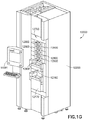
- FIG. 10 is a schematic illustration of a portion of a substrate transport apparatus in accordance with aspects of the disclosed embodiment.
- FIG. 11 is a schematic illustration of a portion of a substrate transport apparatus in accordance with aspects of the disclosed embodiment.
- FIG. 12 is a schematic illustration of a portion of a substrate transport apparatus in accordance with aspects of the disclosed embodiment
- FIG. 13 is a flow chart of a method of operation of a substrate transport apparatus in accordance with one or more aspects of the disclosed embodiment.
- FIG. 14 is a flow chart of a method of operation of a substrate transport apparatus in accordance with one or more aspects of the disclosed embodiment.
- FIGS. 1A-1D there are shown schematic views of substrate processing apparatus or tools incorporating the aspects of the disclosed embodiment as will be further described herein.
- FIGS. 1A-1D there are shown schematic views of substrate processing apparatus or tools incorporating the aspects of the disclosed embodiment as will be further described herein.
- the aspects of the disclosed embodiment will be described with reference to the drawings, it should be understood that the aspects of the disclosed embodiment can be embodied in many forms.
- any suitable size, shape or type of elements or materials could be used.
- the aspects of the disclosed embodiment provide for a substrate transport apparatus including an independent feedthrough drive for control of accessories mounted to the substrate transport apparatus 100 .
- electrical power and/or motive power is provided mechanically to one or more accessories mounted/coupled to the substrate transport apparatus 100 without any feedthroughs penetrating through isolation or seal barriers between an external environment and an isolated/closed internal environment of the transfer chamber (such as a vacuum transfer chamber) in which the substrate transport apparatus 100 is located.
- the drive section 125 of the substrate transport apparatus 100 includes a kinematic portion 125 KP and an accessory portion 125 AP as will be described below.
- the accessory portion 125 AP provides the electrical power and/or motive power from within the isolated internal environment.
- a substrate processing apparatus 11090 such as for example a semiconductor tool station is shown in accordance with aspects of the disclosed embodiment.
- a semiconductor tool station is shown in the drawings, the aspects of the disclosed embodiment described herein can be applied to any tool station or application employing robotic manipulators.
- the semiconductor tool station 11090 is shown as a cluster tool, however the aspects of the disclosed embodiment may be applied to any suitable tool station such as, for example, a linear tool station such as that shown in FIGS. 1C and 1D and described in U.S. Pat. No. 8,398,355, entitled “Linearly Distributed Semiconductor Workpiece Processing Tool,” issued Mar. 19, 2013, the disclosure of which is incorporated by reference herein in its entirety.
- the semiconductor tool station 11090 generally includes an atmospheric front end 11000 , a vacuum load lock 11010 and a vacuum back end 11020 .
- the semiconductor tool station may have any suitable configuration.
- the components of each of the atmospheric front end 11000 , vacuum load lock 11010 , and vacuum back end 11020 may be connected to a controller 11091 which may be part of any suitable control architecture such as, for example, a clustered architecture control.
- the control system may be a closed loop controller having a master controller, cluster controllers and autonomous remote controllers such as those disclosed in U.S. Pat. No. 7,904,182 entitled “Scalable Motion Control System” issued on Mar. 8, 2011 the disclosure of which is incorporated herein by reference in its entirety.
- the controller 11091 includes any suitable memory and processor(s) that include non-transitory program code for operating the semiconductor tool station 11090 to effect handling of substrates S (see FIG. 1C ) as described herein.
- the controller 11091 is configured to determine the location of the substrate relative to the end effector and/or the substrate holding station to effect picking and placing of the substrates S ( FIG. 1C ).
- the controller 11091 is configured to receive detection signals corresponding to one or more features of the end effector and/or transport arm of a substrate transport apparatus/robot and determine the location of the substrate relative to the end effector and/or the substrate holding station to effect picking and placing of the substrates and/or a position of one or more end effector tines.
- the atmospheric front end 11000 generally includes load port modules 11005 and a mini-environment 11060 such as for example an equipment front end module (EFEM).
- the load port modules 11005 may be box opener/loader to tool standard (BOLTS) interfaces that conform to SEMI standards E15.1, E47.1, E62, E19.5 or E1.9 for 300 mm load ports, front opening or bottom opening boxes/pods and cassettes.
- the load port modules 11005 may be configured as 200 mm substrate or 450 mm substrate interfaces or any other suitable substrate interfaces such as for example larger or smaller substrates or flat panels for flat panel displays. Although two load port modules 11005 are shown in FIG.
- any suitable number of load port modules 11005 may be incorporated into the atmospheric front end 11000 .
- the load port modules 11005 may be configured to receive substrate carriers or cassettes 11050 from an overhead transport system, automatic guided vehicles, person guided vehicles, rail guided vehicles or from any other suitable transport method.
- the load port modules 11005 may interface with the mini-environment 11060 through load ports 11040 .
- the load ports 11040 allow the passage of substrates between the substrate cassettes 11050 and the mini-environment 11060 .
- the mini-environment 11060 generally includes any suitable substrate transport apparatus 11013 that incorporates one or more aspects of the disclosed embodiment described herein.
- the substrate transport apparatus 11013 may be a track mounted robot such as that described in, for example, U.S. Pat. No. 6,002,840, the disclosure of which is incorporated by reference herein in its entirety or in other aspects, any other suitable substrate transport apparatus 11013 having any suitable configuration.
- the mini-environment 11060 may provide a controlled, clean zone for substrate transfer between multiple load port modules and the vacuum back end 11020 .
- the vacuum load lock 11010 may be located between and connected to the mini-environment 11060 and the vacuum back end 11020 . It is noted that the term vacuum as used herein may denote a high vacuum such as 10 ⁇ 5 Torr or below in which the substrates are processed.
- the vacuum load lock 11010 generally includes atmospheric and vacuum slot valves. The slot valves may provide the environmental isolation employed to evacuate the load lock after loading a substrate from the atmospheric front end 11000 and to maintain the vacuum in the transport chamber when venting the lock with an inert gas such as nitrogen.
- the load lock 11010 includes an aligner 11011 for aligning a fiducial of the substrate to a desired position for processing.
- the vacuum load lock 11010 may be located in any suitable location of the substrate processing apparatus 11090 and have any suitable configuration and/or metrology equipment.
- the vacuum back end 11020 generally includes a transport chamber 11025 , one or more processing station(s) or module(s) 11030 and any suitable transport robot or apparatus 11014 .
- the substrate transport apparatus 11014 will be described below and may be located within the transport chamber 11025 to transport substrates between the vacuum load lock 11010 and the various processing stations 11030 .
- the processing stations 11030 may operate on the substrates through various deposition, etching, or other types of processes to form electrical circuitry or other desired structure on the substrates.
- Typical processes include but are not limited to thin film processes that use a vacuum such as plasma etch or other etching processes, chemical vapor deposition (CVD), plasma vapor deposition (PVD), implantation such as ion implantation, metrology, rapid thermal processing (RTP), dry strip atomic layer deposition (ALD), oxidation/diffusion, forming of nitrides, vacuum lithography, epitaxy (EPI), wire bonder and evaporation or other thin film processes that use vacuum pressures.
- the processing stations 11030 are connected to the transport chamber 11025 to allow substrates to be passed from the transport chamber 11025 to the processing stations 11030 and vice versa.
- the load port modules 11005 and load ports 11040 are substantially directly coupled to the vacuum back end 11020 so that a cassette 11050 mounted on the load port interfaces substantially directly (e.g. in one aspect at least the mini-environment 11060 is omitted while in other aspects the vacuum load lock 11010 is also omitted such that the cassette 11050 is pumped down to vacuum in a manner similar to that of the vacuum load lock 11010 ) with a vacuum environment of the transfer chamber 11025 and/or a processing vacuum of a processing station 11030 (e.g. the processing vacuum and/or vacuum environment extends between and is common between the processing station 11030 and the cassette 11050 ).
- a cassette 11050 mounted on the load port interfaces substantially directly (e.g. in one aspect at least the mini-environment 11060 is omitted while in other aspects the vacuum load lock 11010 is also omitted such that the cassette 11050 is pumped down to vacuum in a manner similar to that of the vacuum load lock 11010 ) with a vacuum environment of the transfer chamber 11025 and/or
- FIG. 1C a schematic plan view of a linear substrate processing system 2010 is shown where a tool interface section 2012 is mounted to a transport chamber module 3018 so that the tool interface section 2012 is facing generally towards (e.g. inwards) but is offset from a longitudinal axis LXA of the transport chamber module 3018 .
- the transport chamber module 3018 may be extended in any suitable direction by attaching other transport chamber modules 3018 A, 3018 I, 3018 J to interfaces 2050 , 2060 , 2070 as described in U.S. Pat. No. 8,398,355, previously incorporated herein by reference.
- Each transport chamber module 3018 , 3018 A, 3018 I, 3018 J includes any suitable substrate transport 2080 , which may include one or more aspects of the disclosed embodiment described herein, for transporting substrates S throughout the linear substrate processing system 2010 and into and out of, for example, processing modules PM (which in one aspect are substantially similar to processing stations 11030 described above).
- each transport chamber module 3018 , 3018 A, 3018 I, 3018 J may be capable of holding an isolated or controlled atmosphere (e.g. N2, clean air, vacuum).
- FIG. 1D there is shown a schematic elevation view of an exemplary processing tool 410 such as may be taken along longitudinal axis LXB of a linear transport chamber 416 .
- tool interface section 12 may be representatively connected to the linear transport chamber 416 .
- tool interface section 12 may define one end of the linear transport chamber 416 .
- the linear transport chamber 416 may have another substrate entry/exit station 412 for example at an opposite end from tool interface station 12 .
- other entry/exit stations for inserting/removing substrates from the linear transport chamber 416 may be provided.
- tool interface section 12 and entry/exit station 412 may allow loading and unloading of substrates from the processing tool 410 .
- substrate may be loaded into the processing tool 410 from one end and removed from the other end.
- the linear transport chamber 416 may have one or more transfer chamber module(s) 18 B, 18 i .
- Each transfer chamber module 18 B, 18 i may be capable of holding an isolated or controlled atmosphere (e.g. N2, clean air, vacuum).
- N2 isolated or controlled atmosphere
- substrate entry/exit station 412 may be a load lock.
- a load lock module may be located between the end entry/exit station (similar to station 412 ) or the adjoining transport chamber module (similar to module 18 i ) may be configured to operate as a load lock.
- transport chamber modules 18 B, 18 i have one or more corresponding substrate transport apparatus 26 B, 26 i , which may include one or more aspects of the disclosed embodiment described herein, located therein.
- the substrate transport apparatus 26 B, 26 i of the respective transport chamber modules 18 B, 18 i may cooperate to provide the linearly distributed substrate transport system in the linear transport chamber 416 .
- the substrate transport apparatus 26 B, 26 i (which may be substantially similar to the substrate transport apparatus 11013 , 11014 of the cluster tool illustrated in FIGS. 1A and 1B ) may have a general SCARA arm configuration (though in other aspects the substrate transport apparatus may have any other desired arrangement such as, for example, a linearly sliding arm 214 as shown in FIG.
- the at least one substrate transport apparatus may have a general configuration known as SCARA (selective compliant articulated robot arm) type design, which includes an upper arm, a forearm and an end-effector, or from a telescoping arm or any other suitable arm design.
- SCARA selective compliant articulated robot arm
- the arm may have a band-driven configuration, a continuous loop configuration, or any other suitable configuration as will be described further below.
- Suitable examples of transfer arms can be found in, for example, U.S. patent application Ser. No. 12/117,415 entitled “Substrate Transport Apparatus with Multiple Movable Arms Utilizing a Mechanical Switch Mechanism” filed on May 8, 2008 and U.S. Pat. No. 7,648,327 issued on Jan.
- the operation of the transfer arms may be independent from each other (e.g. the extension/retraction of each arm is independent from other arms), may be operated through a lost motion switch or may be operably linked in any suitable way such that the arms share at least one common drive axis.
- the SCARA arm(s) may have one link, two links, or any suitable number of links and may have any suitable drive pulley arrangement such as a 2:1 shoulder pulley to elbow pulley arrangement and a 1:2 elbow pulley to wrist pulley arrangement.
- the substrate transport apparatus may have any other desired arrangement such as a frog-leg arm 216 ( FIG. 2A ) configuration, a leap frog arm 217 ( FIG. 2D ) configuration, a bi-symmetric arm 218 ( FIG. 2C ) configuration, or any other suitable configuration.
- the transfer arm 219 includes at least a first and second articulated arm 219 A, 219 B where each arm 219 A, 219 B includes an end effector 219 E configured to hold at least two substrates S 1 , S 2 side by side in a common transfer plane (each substrate holding location of the end effector 219 E shares a common drive for picking and placing the substrates S 1 , S 2 ) where the spacing DX between the substrates S 1 , S 2 corresponds to a fixed spacing between side by side substrate holding locations.
- Suitable examples of substrate transport apparatus can be found in U.S. Pat. No. 6,231,297 issued May 15, 2001, U.S. Pat. No. 5,180,276 issued Jan.
- the arms of the substrate transport apparatus 26 B, 26 i may be arranged to provide what may be referred to as fast swap arrangement allowing the transport to quickly swap substrates (e.g. pick a substrate from a substrate holding location and then immediately place a substrate to the same substrate holding location) from a pick/place location.
- the substrate transport apparatus 26 B, 26 i may have any suitable drive section (e.g. coaxially arranged drive shafts, side by side drive shafts, horizontally adjacent motors, vertically stacked motors), for providing each arm with kinematic motion in any suitable number (N) of degrees of freedom (DOF) (e.g.
- the modules 56 A, 56 , 30 i may be located interstitially between transfer chamber modules 18 B, 18 i and may define suitable processing modules, load lock(s) LL, buffer station(s), metrology station(s) or any other desired station(s).
- interstitial modules such as load locks 56 A, 56 and substrate station 30 i , may each have stationary substrate supports/shelves 56 S 1 , 56 S 2 , 30 S 1 , 30 S 2 that may cooperate with the substrate transport apparatus to effect transport or substrates through the length of the linear transport chamber 416 along longitudinal axis LXB of the linear transport chamber 416 .
- substrate(s) may be loaded into the linear transport chamber 416 by tool interface section 12 .
- the substrate(s) may be positioned on the support(s) of load lock module 56 A with the transport arm 15 of the interface section.
- the substrate(s), in load lock module 56 A may be moved between load lock module 56 A and load lock module 56 by the substrate transport apparatus 26 B in module 18 B, and in a similar and consecutive manner between load lock 56 and substrate station 30 i with substrate transport apparatus 26 i (in module 18 i ) and between station 30 i and station 412 with substrate transport apparatus 26 i in module 18 i .
- This process may be reversed in whole or in part to move the substrate(s) in the opposite direction.
- substrates may be moved in any direction along longitudinal axis LXB and to any position along the transport chamber 416 and may be loaded to and unloaded from any desired module (processing or otherwise) communicating with the transport chamber 416 .
- interstitial transport chamber modules with static substrate supports or shelves may not be provided between transport chamber modules 18 B, 18 i .
- transport arms of adjoining transport chamber modules may pass off substrates directly from end effector or one transport arm to end effector of another transport arm to move the substrate through the transport chamber 416 .
- the processing station modules may operate on the substrates through various deposition, etching, or other types of processes to form electrical circuitry or other desired structure on the substrates.
- the processing station modules are connected to the transport chamber modules to allow substrates to be passed from the transport chamber 416 to the processing stations and vice versa.
- a suitable example of a processing tool with similar general features to the processing apparatus depicted in FIG. 1D is described in U.S. Pat. No. 8,398,355, previously incorporated by reference in its entirety.
- FIG. 1E is a schematic illustration of a semiconductor tool station 11090 A which may be substantially similar to the semiconductor tool stations described above.
- the semiconductor tool station 11090 A includes separate/distinct in-line processing sections 11030 SA, 11030 SB, 11030 SC connected to a common atmospheric front end 11000 .
- at least one of the in-line processing sections 11030 SA, 11030 SB, 11030 SC is configured to process a substrate S 1 , S 2 , S 3 that has a different predetermined characteristic than the substrates processed in the other in-line processing sections 11030 SA, 11030 SB, 11030 SC.
- the predetermined characteristic may be a size of the substrate.
- in-line processing section 11030 SA may be configured to process 200 mm diameter substrates
- in-line processing section 11030 SB may be configured to process 150 mm substrates
- in-line processing section 11030 SC may be configured to process 300 mm substrates.
- at least one of the substrate transport apparatus 11013 , 11014 is configured to transport the different sized substrates S 1 , S 2 , S 3 with a common end effector.
- each of the load port modules 11050 may be configured to hold and interface with, on a common load port module, cassettes 11050 which hold different size substrates S 1 , S 2 , S 3 .
- each load port module 11050 may be configured to hold a predetermined cassette corresponding to a predetermined sized substrate. Processing substrates of different sizes with at least one common substrate transport apparatus 11013 , 11014 may increase throughput and decrease machine down time with respect to single substrate batch processing.
- FIG. 1F is a schematic illustration of a semiconductor tool station 11090 B substantially similar to semiconductor tool station 11090 .
- the process modules 11030 and load port modules 11005 are configured to process substrates having different sizes as described above with respect to semiconductor tool station 11090 A.
- the process modules 11030 may be configured to process substrates having different sizes or in other aspects, process modules may be provided that correspond to the different size substrates being processed in the semiconductor tool station 11090 B.
- FIGS. 1G and 1H the aspects of the disclosed embodiment may be incorporated into sorting machines and/or stockers.
- the sorting machines and/or stockers may be used to sort or stock substrates (such as those described above).
- FIGS. 1G and 1H illustrate a manipulating device 12000 substantially similar to that described in U.S. Pat. No. 7,699,573 issued on Apr. 20, 2010, the disclosure of which is incorporated herein by reference in its entirety.
- the manipulating device 12000 may be configured to manipulate substrates such as reticles but in other aspects the manipulating device 12000 may be configured to manipulate any suitable substrate.
- the manipulating device 12000 may be a modular device having a housing 12200 for maintaining clean a room environment within the housing 12200 .
- the manipulating device 12000 includes an input/output station 12700 integrated into the housing 12200 that includes panels 12600 .
- Each panel 12600 belongs to an input/output unit 12800 which is also modular.
- One edge of an opening 12900 of the respective panel 12600 is provided with a contour that corresponds at least approximately to the outer contour of each type of substrate (such as e.g. a reticle transport box) that is to be processed by the manipulating device 12000 .
- the openings 12900 are configured so that the substrates can be input/output through the openings 12900 to and from the manipulating device 12000 .
- the manipulating device 12000 also includes drawers 12170 , 12160 that are components of additional input/output units 12800 of input/output station 12700 .
- the drawers 12170 , 12160 may have different structural height and can be pulled out to accept larger transport boxes, for example, those which can accommodate more than one substrate, i.e. the larger transport boxes can be introduced into the manipulating device 12000 through the drawers 12160 , 12170 .
- the manipulating device 12000 also includes at least one substrate transport apparatus 11014 substantially similar to those described herein.
- the at least one substrate transport apparatus 11014 is configured to transport the one or more substrates within the manipulating device 12000 for sorting, stocking or for any other processing operation(s). It is noted that the configuration of the manipulating device 12000 described herein is exemplary and in other aspects, the manipulating device 12000 may have any suitable configuration for sorting and/or stocking substrates in any suitable manner.
- the manipulating device 12000 may be included in the semiconductor tool stations of FIGS. 1A-1F described above.
- the manipulating device 12000 may be incorporated in the atmospheric front end 11000 of the semiconductor tool stations/systems 11090 , 2010 , 11090 A, 11090 B as a load port and/or atmospheric transfer chamber; while in other aspects the manipulating device 12000 may be incorporated in the vacuum back end 11020 of the semiconductor tool stations/systems 11090 , 2010 , 11090 A, 11090 B as a process module and/or a transfer chamber.
- the manipulating device 12000 may be coupled to the atmospheric front end 11000 in place of the vacuum back end 11020 .
- manipulating device 12000 incorporating aspects of the disclosed embodiment could store a multitude of different shaped and/or sized substrates in a common housing using a common end effector.
- the substrate transport apparatus 100 is substantially similar to the substrate transport apparatus described above with respect to FIGS. 1A-1H and may include one or more of the arm configurations described above with respect to FIGS. 2A-2E .
- the substrate transport apparatus 100 may be employed in any suitable atmospheric or vacuum environment such as those described above with respect to the semiconductor tool stations.
- the substrate transport apparatus 100 includes a frame 106 , at least one substrate transport arm 110 and a base/housing 120 mounted to the frame 106 and coupled to the substrate transport arm 110 .
- the base 120 includes a drive section 125 disposed therein and coupled to the substrate transport arm 110 .
- Any suitable controller such as controller 11091 described above, may be connected to the drive section 125 and includes any suitable program code for effecting operation of the substrate transport apparatus 100 as described herein.
- the drive section 125 is a four axis drive section while in other aspects the drive section 125 may include any suitable number of drive axes, e.g., two, three, or more than four axes.
- the drive section 125 generally comprises a coaxial drive shaft assembly 126 and more than one motor 125 M 1 - 125 M 4 .
- the more than one motor 125 M 1 - 125 M 4 may have any suitable arrangement, such as horizontally adjacent, vertically stacked, or any other suitable arrangement (as will be described herein) and may be located in a common housing (i.e., base/housing 120 ).
- drive motors described herein may be permanent magnet motors, variable reluctance motors (having at least one salient pole with corresponding coil units and at least one respective rotor having at least one salient pole of magnetic permeable material), or any other suitable drive motors.
- the drive section 125 is shown in accordance with an aspect of the disclosed embodiment.
- the drive section 125 has a coaxial drive arrangement, however other aspects may have any suitable drive arrangement.
- the drive section 125 is disposed in a common housing 120 , at least partially housing the drive shaft assembly 126 where the drive section 125 includes four drive shafts 126 S 1 - 126 S 4 and four motors 125 M 1 - 125 M 4 .
- the drive section 125 of the substrate transport apparatus 100 is illustrated in FIGS. 3 and 3A as having four motors and four drive shafts, other exemplary drive section configurations depicted in FIGS. 4-7 may have any suitable number of motors and drive shafts and any suitable configuration.
- drive section 125 ′ illustrated in FIG. 4 , includes a two motor off axis configuration such that two drive shafts 126 S 1 , 126 S 2 are arranged coaxially and two motors 125 M 1 , 125 M 2 are arranged staggered/off axis from the coaxial drive shafts 126 S 1 , 126 S 2 .
- any suitable transmissions 127 T 1 , 127 T 2 couple the motors 125 M 1 , 125 M 2 to the respective drive shafts 126 S 1 , 126 S 2 .
- Drive section 125 ′′ illustrated in FIG.
- Drive section 125 ′′′ illustrated in FIG. 6 , includes a four motor nested or concentric configuration such that four drive shafts 126 S 1 - 126 S 4 are arranged coaxially and four motors 125 M 1 - 125 M 4 are arranged in a nested coaxial arrangement.
- motor 125 M 2 is nested within (e.g., is radially surrounded by) motor 125 M 1 and motor 125 M 3 is nested within motor 125 M 4 .
- the nested motors 125 M 1 , 125 M 2 are coaxially arranged relative to nested motors 125 M 3 , 125 M 4 so that nested motors 125 M 1 , 125 M 2 are disposed coaxially above nested motors 125 M 3 , 125 M 4 .
- Drive section 125 ′′′′, illustrated in FIG. 7 includes three coaxial drive shafts 126 S 1 - 126 S 3 and three motors 125 M 1 - 125 M 3 . Two of the motors 125 M 1 , 125 M 2 are in the manner described above with respect to FIG. 6 and are stacked above or below the third motor 125 M 3 .
- the first motor 125 M 1 of the drive section 125 includes a stator 125 ST 1 and a rotor 125 RT 1 connected to the outer drive shaft 126 S 1 .
- the second motor 125 M 2 of the drive section 125 includes a stator 125 ST 2 and a rotor 125 RT 2 connected to inner drive shaft 126 S 2 .
- the third motor 125 M 3 of the drive section 125 includes a stator 125 ST 3 and a rotor 125 RT 3 connected to drive shaft 126 S 3 .
- the fourth motor 125 M 4 of the drive section 125 includes a stator 125 ST 4 and a rotor 125 RT 4 connected to the fourth drive shaft 126 S 4 .
- the four stators 125 ST 1 - 125 ST 4 of the four motors 125 M 1 - 125 M 4 are stationarily attached to the common housing 120 at different vertical heights or locations within the common housing 120 .
- the motors 125 M 1 - 125 M 4 are illustrated with motor 125 M 1 being at a top portion of the common housing 120 followed by motor 125 M 3 directly below motor 125 M 1 , motor 125 M 4 directly below motor 125 M 3 , and motor 125 M 2 being at a bottom portion of the common housing 120 , any suitable arrangement of the motors 125 M 1 - 125 M 4 may be utilized for driving the respective drive shafts 126 S 1 - 126 S 4 .
- the stator(s) 125 ST 1 - 125 ST 4 of the four motors 125 M 1 - 125 M 4 may be located in an “external” or “non-sealed” environment that is sealed from an atmosphere in which the substrate transport arm 110 operates (the atmosphere in which the substrate transport arm operates is referred to herein as a “sealed” environment which may be a vacuum or any other suitable environment) through the employment of any suitable isolation wall or barrier 300 while the rotor(s) 125 RT 1 - 125 RT 4 are located within the sealed environment.
- the term “isolation wall” as used herein may refer to a wall made of any suitable non-ferromagnetic material that may be disposed between the moving parts of the drive section and/or sensors (associated with the drive) and the corresponding stationary parts of the drive section and/or sensors.
- the barrier 300 may be a “can-seal” being one substantially continuous seal common to the motors 125 M 1 - 125 M 4 of the drive section 125 to isolate a motor rotor from a corresponding motor stator via a hermetically sealed non-magnetic wall.
- a suitable example of a “can-seal” can be found in, for example, U.S. application Ser. No. 14/540,072 filed Nov.
- each of the rotors 125 RT 1 - 125 RT 4 of the motors 125 M 1 - 125 M 4 are connected to a respective drive shaft 126 S 1 - 126 S 4 and generally comprise permanent magnets, but may alternatively comprise a magnetic induction rotor that does not have permanent magnets.
- the drive shafts 126 S 1 - 126 S 4 may be mechanically supported within the common housing/base 120 by any suitable bearings BR.
- the drive shafts 126 S 1 - 126 S 4 may be magnetically suspended (e.g. substantially without contact), e.g., within the base 120 in any suitable manner such as described in U.S. Pat. No. 8,283,813 entitled “Robot Drive with Magnetic Spindle Bearings” issued on Oct. 9, 2012 and U.S. Pat. No. 8,008,884 entitled “Substrate Processing Apparatus with Motors Integral to Chamber Walls” issued on Aug. 30, 2011, the disclosures of which are incorporated by reference herein in their entireties.
- Each drive shaft 126 S 1 - 126 S 4 of the drive section 125 is driven by its respective motor 125 M 1 - 125 M 4 , as will be further described below.
- the drive section 125 includes a kinematic portion 125 KP and an accessory portion 125 AP.
- at least one of the more than one motor 125 M 1 - 125 M 4 defines the kinematic portion 125 KP of the drive section 125 (e.g., motors 125 M 1 - 125 M 3 define the kinematic portion 125 KP in FIGS. 3 and 3A ) and at least another of the more than one motor 125 M 1 - 125 M 4 defines the accessory portion 125 AP of the drive section 125 (e.g., motor 125 M 4 defines the accessory portion 125 AP in FIGS. 3 and 3A ).
- the accessory portion 125 AP is located adjacent the kinematic portion 125 KP, for example, in the base 120 .
- the kinematic portion 125 KP and accessory portion 125 AP are depicted as being located in the base 120 , the kinematic portion 125 KP and accessory portion 125 AP may be located adjacent one another on a shoulder joint 111 J, elbow joint 112 J, or any other suitable location of the substrate transport apparatus 100 , such as within an upper arm link 111 or forearm link 112 .
- the kinematic portion 125 KP may include N number of motors of the more than one motor 125 M 1 - 125 M 4 while the accessory portion 125 AP includes at least another motor of the more than one motor 125 M 1 - 125 M 4 , different and distinct from the N number of motors of the kinematic portion 125 KP.
- the N number of motors is one motor (e.g., motor 125 M 1 ), such that the kinematic portion 125 KP includes one of the two motors 125 M 1 , 125 M 2 while the other motor (e.g., 125 M 2 ) of the two motors 125 M 1 , 125 M 2 defines the accessory portion 125 AP.
- the N number of motors is one motor (e.g., motor 125 M 1 ), such that the kinematic portion 125 KP includes one of the two motors 125 M 1 , 125 M 2 while the other motor (e.g., 125 M 2 ) of the two motors 125 M 1 , 125 M 2 defines the accessory portion 125 AP.
- a drive section having three motors 125 M 1 - 125 M 3 such as drive sections 125 ′′ and 125 ′′′′ illustrated in FIGS.
- the N number of motors is two motors (e.g., 125 M 1 , 125 M 2 ), such that the kinematic portion 125 KP includes two of the three motors 125 M 1 - 125 M 3 while the other motor (e.g., 125 M 3 ) of the three motors 125 M 1 - 125 M 3 defines the accessory portion 125 AP.
- the N number of motors is two motors (e.g., 125 M 1 , 125 M 2 ), such that the kinematic portion 125 KP includes two of the three motors 125 M 1 - 125 M 3 while the other motor (e.g., 125 M 3 ) of the three motors 125 M 1 - 125 M 3 defines the accessory portion 125 AP.
- a drive section having four motors 125 M 1 - 125 M 4 such as drive sections 125 and 125 ′′′ illustrated in FIGS.
- the N number of motors is three motors (e.g., 125 M 1 - 125 M 3 ), such that the kinematic portion 125 KP includes three of the four motors 125 M 1 - 125 M 4 while the other motor (e.g., 125 M 4 ) of the four motors 125 M 1 - 125 M 4 defines the accessory portion 125 AP.
- each of the N number of motors of the kinematic portion 125 KP are provided to independently (alone or in combination) drive and effect kinematic motion of the substrate transport arm 110 , such that each of the N number of motors provides an independent drive axis T 1 , T 2 , . . .
- Tn effected as a corresponding independent rotation axis at each arm link joint ( 111 J, 112 J) and wrist joint 113 J that generates alone or in combination motions of the substrate transport arm 110 that may be described as (R ⁇ , ⁇ ).
- a substrate transport arm 110 with N 4 motors, the kinematic portion 125 KP has four degrees-of-freedom (R 1 , R 2 , ⁇ , ⁇ ) of kinematic motion.
- R 1 , R 2 , ⁇ , ⁇ degrees-of-freedom
- the kinematic motion includes displacement of the substrate transport arm 110 , relative to the frame, along a motion path MP.
- accessory portion 125 AP is described in the examples above as having one motor, in other aspects, the accessory portion 125 AP may include any suitable number of motors for driving/powering any suitable number of accessories disposed on, e.g., the substrate transport arm 110 .
- the substrate transport apparatus 100 includes at least one substrate transport arm 110 mounted to the base 120 and coupled to the drive section 125 .
- the four motor drive system of FIGS. 3-3A is being used as an example and that the aspects of the disclosed embodiment described below apply equally to the drive section configurations illustrated in FIGS. 4-7 or any other suitable drive section.
- the at least one substrate transport arm 110 may be any suitable articulated arm.
- the at least one substrate transport arm 110 may be a SCARA arm.
- the substrate transport arm 110 may have a configuration substantially similar to any one or more of the arms previously described with respect to FIGS.
- the substrate transport apparatus includes one substrate transport arm 110 while in FIG. 9 , the substrate transport apparatus 100 includes two substrate transport arms 110 A, 110 B.
- Each substrate transport arm 110 A, 110 B may be substantially similar to the arm depicted in FIG. 8 unless otherwise noted.
- each arm 110 A, 110 B may be independently operable where each arm is extended and retracted independent of the other arm, while in other aspects, the arms 110 A, 110 B may share a common motor so that the common motor extends and retracts the arms 110 A, 110 B substantially in unison.
- each arm link 111 , 112 , 113 may be driven by a respective degree-of-freedom of the drive section 125 , while in other aspects, one or more of the links 111 , 112 , 113 may be slaved as will be further described below.
- the at least one substrate transport arm 110 includes an upper arm link 111 , a forearm link 112 , and at least one end effector 113 .
- the upper arm link 111 is rotatably connected at a proximate end of the upper arm link 111 to the base 120 about a shoulder axis of rotation 111 SA of the shoulder joint 111 J.
- the forearm link 112 is rotatably connected at a proximate end of the forearm link 112 to a distal end of the upper arm link 111 about an elbow axis of rotation 112 EA of the elbow joint 112 J.
- the end effector 113 is rotatably coupled to a distal end of the forearm link 112 about a wrist axis of rotation 113 WA of a wrist joint 113 J. While only a single end effector 113 is illustrated as being coupled to the wrist joint 113 J, in other aspects any suitable number of end effectors may be coupled to the wrist joint 113 J to effect batch transfers of substrates or fast swapping of substrates.
- each link of the substrate transport arm 110 is independently driven, each link of the substrate transport arm 110 (i.e. the upper arm link 111 , forearm link 112 , and end effector 113 ) is coupled to a respective drive shaft 126 S 1 - 126 S 3 with a respective transmission 127 T 1 - 127 T 3 as will be further described below.
- one or more links of the substrate transport arm 110 may be slaved to another arm link or the base 120 so that the substrate transport arm 110 is extended and retracted with fewer motors than arm links with the end effector 113 following a predetermined motion path MP (see FIG. 1B ).
- the kinematic portion 125 KP of the drive section 125 may include motors 125 M 1 - 125 M 4
- accessory portion 125 AP includes motors 125 M 5 , 125 M 6 .
- the motors of the kinematic portion 125 KP are coupled to a respective drive shaft 126 S 1 - 126 S 4 to drive the substrate transport arms 110 A, 110 B.
- motor 125 M 1 is coupled to drive shaft 126 S 1 to drive the upper arm link 111 B of substrate transport arm 110 B and motor 125 M 2 is coupled to drive shaft 126 S 2 to drive the forearm link 112 B of substrate transport arm 110 B.
- the end effector 113 B is slaved to the upper arm link 111 B via transmission 127 TB.
- Motor 125 M 3 is coupled to drive shaft 126 S 3 to drive the upper arm link 111 A of substrate transport arm 110 A.
- Motor 125 M 4 is coupled to drive shaft 126 S 4 to drive the forearm link 112 A of substrate transport arm 110 A.
- the end effector 113 A is slaved to the upper arm link 111 A via transmission 127 TA.
- the motors 125 M 5 , 125 M 6 of the accessory portion 125 AP are coupled to a respective accessory device 130 on a respective substrate transport arm 110 A, 110 B.
- motor 125 M 5 is coupled to drive shaft 126 S 5 .
- Transmission 127 T 5 is coupled to the drive shaft 126 S 5 and fed through substrate transport arm 110 B to elbow joint 112 JB where power is provided to accessory device 130 B.
- Substrate transport arm 110 A has a substantially similar accessory feedthrough as substrate transport arm 110 B, such that motor 125 M 6 is coupled to drive shaft 126 S 6 .
- Transmission 127 TA is couple to drive shaft 126 S 6 and fed through to elbow joint 112 JA where power is provided to accessory device 130 A
- the substrate transport arm 110 has N number of degrees-of-freedom, defined by the N number of the more than one drive motors 125 M 1 - 125 M 4 , of the kinematic portion 125 KP.
- the upper arm link 111 , forearm link 112 and end effector 113 are coupled to a respective motor 125 M 1 - 125 M 3 , via the drive shafts 126 S 1 - 126 S 3 , of the kinematic portion 125 KP of the drive section 125 .
- the first drive shaft 126 S 1 is drivingly connected to motor 125 M 1 for driving rotation of the upper arm link 111 about the shoulder axis of rotation 111 SA of the shoulder joint 111 J.
- the second drive shaft 126 S 2 (which in this aspect is concentric/coaxial with the first drive shaft 126 S 1 ) is drivingly connected to motor 125 M 2 for driving rotation of the forearm link 112 about the elbow axis of rotation 112 EA of the elbow joint 112 J.
- the third drive shaft 126 S 3 (which in this aspect is concentric/coaxial with the first and second drive shafts 126 S 1 , 126 S 2 ) is drivingly connected to motor 125 M 3 for driving rotation of the end effector 113 about the wrist axis of rotation 113 WA of the wrist joint 113 J.
- the kinematic portion 125 KP of the drive section 125 is coupled to the substrate transport arm 110 and configured to drive a respective drive shaft 126 S 1 - 126 S 3 , such that the kinematic portion 125 KP effects the kinematic motion of the substrate transport arm 110 .
- a kinematic motion path of the substrate transport arm 110 is described by at least one of the N number of degrees-of-freedom.
- the substrate transport arm 110 includes one or more transmissions 127 T 1 - 127 T 3 .
- a first transmission 127 T 1 includes a coupling 306 drivingly coupling drive shaft 126 S 1 to the upper arm link 111 .
- a second transmission 127 T 2 includes pulleys 301 , 303 and a transmission member 304 for drivingly coupling drive shaft 126 S 2 to the forearm link 112 .
- a third transmission 127 T 3 includes pulleys 305 , 307 , 311 , 320 , transmission members 309 , 310 , and a post 308 for drivingly coupling drive shaft 126 S 3 to the end effector 113 .
- the upper arm link 111 is fixedly attached, via the first transmission 127 T 1 , to the outer drive shaft 126 S 1 such that the upper arm link 111 rotates with the drive shaft 126 S 1 as a unit about the shoulder axis of rotation 111 SA.
- Pulley 301 of the second transmission 127 T 2 is fixedly attached to drive shaft 126 S 2 so as to rotate with the drive shaft 126 S 2 as a unit about the shoulder axis of rotation 111 SA.
- Pulley 303 of the second transmission 127 T 2 is mounted to an inner surface of the upper arm link 111 about the elbow axis of rotation 112 EA.
- the transmission member 304 extends between pulley 301 and pulley 303 .
- any suitable type of transmission member may be used to couple the pulleys 301 , 303 , such as for example, a belt, band or chain and further that the transmission member may have any suitable configuration such a split band transmission or continuous loop transmission.
- suitable examples of split band and continuous loop transmissions can be found in, for example, U.S. patent application Ser. No. 14/469,260 entitled “Substrate Transport Apparatus” and filed on Aug. 26, 2014, and U.S. Pat. No. 9,230,841 issued Jan. 5, 2016, the disclosures of which are incorporated by reference herein in their entireties.
- the forearm link 112 is fixedly attached to the pulley 303 so as to rotate with the pulley 303 about the elbow axis of rotation 112 EA. As such, as drive shaft 126 S 2 rotates, the forearm link 112 rotates about the elbow axis of rotation 112 EA.
- Pulley 305 of the third transmission 127 T 3 is fixedly coupled to drive shaft 126 S 3 so as to rotate with the drive shaft 126 S 3 as a unit about the shoulder axis of rotation 111 SA.
- Pulley 307 is mounted to an inner surface of the upper arm link 111 and pulley 320 is mounted to an inner surface of the forearm link 112 , both pulleys 307 , 320 being mounted about the elbow axis of rotation 112 EA and having post 308 extending across the articulated elbow joint 112 J coupling the two pulleys 307 , 320 so that the pulleys 307 , 320 rotate as a unit about the elbow axis of rotation 112 EA.
- Transmission member 309 extends between pulley 305 and pulley 307 .
- Pulley 311 is mounted to an inner surface of the forearm link 112 about the wrist axis of rotation 113 WA.
- Transmission member 310 is extends between pulley 311 and pulley 320 .
- the end effector 113 is fixedly attached to the pulley 311 so as to rotate with the pulley 311 about the wrist axis of rotation 113 EA. As such as drive shaft 126 S 3 rotates, the end effector 113 rotates about the wrist axis of rotation 113 WA.
- the substrate transport arm 110 has 3 degrees-of-freedom defined by the three motors 125 M 1 - 125 M 3 .
- the substrate transport arm 110 may have a slaved configuration such that the single motor drives a transmission operably coupled to each of the upper arm link 111 , the forearm link 112 , and the end effector 113 .
- the accessory portion 125 AP of the drive section 125 is operably coupled to and configured to drive one or more accessory device(s) 130 .
- the accessory portion 125 AP of the drive section 125 is operably coupled to the one or more accessory device(s) 130 so as to power and/or drive the one or more accessory device(s) 130 .
- the one or more accessory device(s) 130 has a degree-of-freedom motion axis accessory to each motion path of the substrate transport arm 110 .
- the accessory portion 125 AP of the drive section 125 has a different and distinct motor(s) than the kinematic portion 125 KP.
- the accessory portion 125 AP having a different and distinct motor(s) provides for the one or more accessory device(s) 130 to be driven independent of the kinematic motion (and each motion path provided thereby) of the substrate transport arm 110 .
- the accessory portion 125 AP of the drive section 125 includes, e.g., motor 125 M 4 coupled to drive shaft 126 S 4 .
- the substrate transport arm 110 further includes at least another transmission 127 T 4 movably mounted within the substrate transport arm 110 , extending from the base 120 through the substrate transport arm 110 to, e.g., the wrist joint 113 J.
- the at least another transmission 127 T 4 is configured to, via drive torque generated by the motor 125 M 4 of the accessory portion 125 AP, drive/power one or more accessory device(s) 130 .
- the at least another transmission 127 T 4 effects drive power of the one or more accessory device(s) 130 independent of the N number of degrees of freedom of the kinematic motion of the substrate transport arm 110 .
- the at least another transmission 127 T 4 includes pulleys 312 , 313 , 317 , 321 , transmission members 312 , 316 , and posts 314 , 318 . It is noted that the at least another transmission 127 T 4 may include more or less pulleys, transmission members, and posts, such as where the accessory portion 125 AP does not extend from the base 120 all the way to the wrist joint 113 J.
- the at least another transmission 127 T 4 of the accessory portion 125 AP may extend from the base 120 partially through the substrate transport arm 110 to, e.g., the elbow joint 112 J or any other portion of, for example, the forearm link 112 or the upper arm link 111 .
- pulley 312 of the at least another transmission 127 T 4 is fixedly coupled to drive shaft 126 S 4 so as to rotate with the drive shaft 126 S 4 as a unit about the shoulder axis 111 SA.
- Pulley 313 is mounted to an inner surface of the upper arm link 111 and pulley 321 is mounted to an inner surface of the forearm link 112 , both pulleys 313 , 321 being mounted about the elbow axis of rotation 112 EA with post 314 extending across the articulated elbow joint 112 J and coupling the two pulleys 313 , 321 so that the pulleys 313 , 321 rotate as a unit about the elbow axis of rotation 112 EA.
- Transmission member 315 is extended between pulley 313 and pulley 321 .
- Pulley 317 is mounted to an inner surface of the forearm link 112 about the wrist axis of rotation 113 WA.
- Transmission member 316 is extended between pulley 316 and pulley 321 .
- the post 318 is coupled to pulley 317 and extends along the wrist joint 113 J where one or more accessory device(s) 130 is attached to the post 308 to be driven/powered as will be further described below.
- the at least another transmission 127 T 4 operably couples the accessory portion 125 AP of the drive section 125 to the one or more accessory device(s) 130 .
- the components of the at least another transmission 127 S 4 are sized or otherwise configured to provide sufficient motion for the kinematic portion 125 KP and the accessory portion 125 AP, such that the accessory portion 125 AP has sufficient freedom of motion to accommodate, without restraint, the kinematic motions of the substrate transport arm 110 and provide drive torque throughout the range of substrate transport arm 110 motion.
- the transmission members 315 , 316 comprise bands
- the pulleys may be sized and the bands may be wrapped around the pulley by an amount sufficient to allow operation of the one or more accessory device(s) 130 without restraining movement of the substrate transport arm 110 .
- the post 318 may include an accessory drive output port 115 as will be further described below.
- the at least another transmission 127 T 4 of the accessory portion 125 AP may not extend all the way through the substrate transport arm 110 to the end effector 113 and may extend partially through to, e.g., the elbow joint 112 J or any other portion of, for example, the forearm link 112 or the upper arm link 111 .
- the configuration of the drive shaft 126 S 1 - 126 S 4 and pulleys 301 , 313 , 305 , 307 , 311 , 312 , 312 , 317 , 320 , 321 may change.
- the accessory portion 125 AP is configured to drive or power one or more accessory device(s) 130 .
- the end effector 113 and/or the substrate transport arm 110 may include, coupled to the end effector 113 or at any suitable location of the substrate transport arm 110 , the one or more accessory device(s) 130 .
- the one or more accessory device(s) 130 may include a gripping mechanism 130 GM, a substrate aligner 130 WA, a power generator 130 PG and/or any other suitable accessory device.
- the accessory portion 125 AP of the drive section 125 which may utilize either the split band or continuous loop transmission as noted above, is configured to power and/or drive each respective characteristic (e.g., gripping, aligning, power generation, or any other suitable operational characteristic) of a respective accessory device 130 GM, 130 WA, 130 PG.
- each respective characteristic e.g., gripping, aligning, power generation, or any other suitable operational characteristic
- each of the one or more accessory device(s) 130 may be easily swapped with another accessory device 130 PG, 130 WA, 130 GM having a different predetermined characteristic.
- the substrate transport arm 110 may be a modular arm, such that different accessory devices 130 PG, 130 WA, 130 GM, each having a respective predetermined characteristic different from the predetermined characteristic of the other accessory devices 130 PG, 130 WA, 130 GM, may be interchanged and mounted on the modular substrate transport arm.
- the modular arm includes the accessory drive output port 115 which may be substantially similar to a power take-off.
- the accessory drive output port 115 may be a release coupling.
- the accessory drive output port 115 may be a pulley of one of the transmission couplings having an inner spline to which the end effector 113 or one or more accessory device(s) 130 is inserted and coupled, such as for example, post 318 .
- the accessory drive output port 115 may be any suitable apparatus to couple the end effector 113 or one or more accessory device(s) 130 to the substrate transport arm 110 .
- the accessory drive output port 115 may be located at the elbow joint 112 J, on the forearm link 112 , on the upper arm link 111 , or in any suitable location.
- the accessory drive output port 115 is configured to receive the end effector 113 or one or more accessory device(s) 130 and integrate the end effector 113 or one or more accessory device(s) 130 with the motor(s) of the accessory portion 125 AP as described herein.
- the gripping mechanism 130 GM is mounted to the end effector 113 in any suitable manner so as to interface with a substrate S supported by a substrate support surface 601 of end effector 113 .
- the gripping mechanism 130 GM includes movable edge grippers 602 , 603 and 604 that are moved toward the substrate S under motive power of the motor 125 M 4 of the accessory portion 125 AP.
- the motor 125 M 4 is coupled to the gripping mechanism 130 GM through transmission 127 T 4 so as to drive movement of the edge grippers 602 , 603 , 604 .
- the transmission 127 T 4 is coupled to a linear actuator 606 of the gripping mechanism 130 GM by a transmission 600 of the gripping mechanism 130 Gm.
- the linear actuator 606 may be a screw or belt drive and the transmission 600 may be any suitable geared or other transmission configured to turn rotary motion of the post 318 (and the accessory drive output port 115 ) (see FIG. 8 ) into motion that drives the linear actuator 606 .
- linear movement of the linear actuator 606 causes respective contact pads 607 , 608 and 609 to engage the edge of the substrate S.
- the contact pads 607 , 608 and 609 may each comprise an upper and lower lip forming an included angle therebetween, the substrate edge being held within the included angle.
- Transmission 127 T 4 is fed through the substrate transport arm 110 to the accessory drive output port 115 located at the wrist joint 113 J as described above.
- Motor 125 M 4 of the accessory portion 125 AP of the drive section 125 (kinematic portion 125 KP is not shown) provides drive power to the accessory drive output port 115 to turn transmission 600 .
- Transmission 600 causes the linear actuator 606 to actuate the gripping mechanism 130 GM to grip the substrate S.
- Another suitable example of an active grip mechanism to which the aspects of the disclosed embodiment may be applied is described in U.S. patent application Ser. No. 10/196,679 (filed on Jul. 15, 2002) which is hereby incorporated by reference in its entirety.
- the end effector may have any other suitable active edge grip mechanism such as a vertical grip mechanism to grip a topside and/or backside of the substrate S.
- FIG. 11 illustrates substrate mapping/presence sensors powered by power generator 130 PG.
- the end effector 113 includes a substrate presence sensor 701 positioned on the end effector 113 to detect the presence or absence of the substrate S on the end effector 113 .
- the end effector 113 may also include a mapping sensor 700 for mapping substrates within the processing tool (such as substrates stacked in a cassette or buffer.
- the sensor 700 is a through beam sensor having a beam emitter 700 A and a beam receiver 700 B. Signals from the sensors 700 , 701 may be transmitted to any suitable controller, such as controller 11091 , in any suitable manner, such as through wireless communication.
- the sensors 700 , 701 are powered by the power generator 130 PG located, in this aspect on the wrist joint 113 J and connected to the accessory drive output port 115 .
- Motor 125 M 4 of the accessory portion 125 AP of the drive section 125 (kinematic portion 125 KP is not shown) provides mechanical/motive power to the accessory drive output port 115 .
- the power generator 130 PG attached to the accessory drive output port 115 is driven by the motor 125 M 4 to generate electric power to power the sensors 700 , 701 and any wireless transmitters coupled to the sensors 700 , 701 .
- the power generator 130 PG is connected to the sensors 700 , 701 via electrical power transmission conduits 703 that provide electrical power from the power generator 130 PG to power the sensors.
- the substrate aligner 130 WA accessory device is illustrated as being attached to end effector 113 in any suitable manner so that the substrate aligner 130 WA supports the substrate S on the end effector 113 .
- the accessory portion 125 AP includes two motors (e.g., 125 M 4 , 125 M 5 —it is noted that the kinematic portion 125 KP of the drive section 125 is not shown) to power/drive the substrate aligner 130 WA.
- the substrate aligner 130 WA includes a base 1200 , a chuck 1201 , and a motor 1202 .
- the base 1200 is generally configured to mount to the end effector 113 of the substrate transfer arm 110 .
- the chuck 1201 is rotatably supported on the base 1200 .
- the chuck 1201 has structures for holding a substrate S by, e.g., passively edge gripping the substrate.
- the motor 1202 is disposed at least partially within the base 1200 and is connected to the chuck 1201 to rotate the chuck 1201 relative to the base 1200 .
- the motor 1202 has an axis of motion R extending substantially through the center C of the substrate S when the substrate is held by the chuck 1201 .
- the substrate aligner 130 WA further includes elevatable supports 1205 which are raised or elevated from the upper surface of the base 1200 (in the direction indicated by arrow Z) to lift the substrate S from the chuck 1201 .
- Motor 1202 Electrical power is received by motor 1202 from, e.g., the power generator 130 PG which as described above is driven by motor 125 M 4 of the accessory portion 125 AP.
- the power generator 130 PG is positioned on the forearm link 112 and connected to accessory drive output port 115 ′ (substantially similar to accessory drive output port 115 ) which is also disposed along a length of the forearm link 112 .
- Transmission 127 T 4 is fed through the substrate transport arm 110 to the accessory drive output port 115 ′ located at the forearm link 112 .
- the power generator 130 PG attached to the accessory drive output port 115 ′ is driven by motor 125 M 4 to generate electrical power to power the motor 1202 via electrical power transmission conduits 703 to rotate the chuck 1201 to a desired orientation.
- the elevatable supports 1205 are provided for the substrate S to be seated on, in an elevated position after rotational alignment of the substrate, while the chuck 1201 is reset, using motor 1202 , to for example a home or zeroed position to align the chuck 1201 with the end effector 113 for placing the substrate S.
- the elevatable supports 1205 may be lowered to return the substrate S to the chuck 1201 .
- the orientation of the substrate S is thus maintained while the chuck 1201 position is reset.
- the elevatable supports 1205 are driven/powered by the second motor 125 M 2 of the accessory portion 125 AP of the drive section 125 .
- Transmission 127 T 5 is fed through the substrate transport arm 110 to the accessory drive output port 115 located at, e.g., the wrist joint 113 J.
- Any suitable transmission 1204 (which may be substantially similar to transmission 600 described above with respect to FIG. 10 ) may be utilized to provide the mechanical motive power from the accessory drive output port 115 to the elevatable supports 1205 .
- the substrate aligner 130 WA may also be configured for one or more of detecting a missing substrate S and/or detecting a substrate thickness.
- the motor 125 M 4 of the accessory portion 125 AP may be utilized for monitoring in-situ movement, via feedback from the motor 125 M 4 of the accessory portion 125 AP.
- in-situ movement monitoring may be realized via monitoring torque of the motor by, e.g., measuring the current draw from the motor 125 M 4 .
- the torque can be monitored to detect, e.g., grip of the substrate S to determine whether the substrate is engaged by the gripper mechanism 130 GM.
- an encoder 500 FIG. 5
- the method 1000 includes providing a frame 106 of substrate transport apparatus 100 ( FIG. 13 , Block 1001 ). The method further includes providing a substrate transport arm 110 connected to the frame 106 , the substrate transport arm 110 having an end effector 113 ( FIG. 13 , Block 1002 ). The method 1000 further includes providing a drive section 125 having at least one motor coupled to the substrate transport arm 110 .
- the at least one motor 125 M 1 - 125 M 3 of the drive section 125 defines a kinematic portion 125 KP of the drive section 125
- another motor 125 M 4 adjacent the at least one motor 125 M 1 - 125 M 3 defines an accessory portion 125 AP of the drive section 125
- the another motor 125 M 4 being different and distinct from the at least one motor 125 M 1 - 125 M 3 ( FIG. 13 , Block 1003 ).
- the method 1000 further includes driving, with the at least one motor, kinematic motion of the substrate transport arm 110 to displace the substrate transport arm 110 along a motion path MP (see FIG. 1B ) relative to the frame 106 ( FIG. 13 , Block 1003 ).
- the method 1000 further includes driving, with the another motor 125 M 4 , one or more accessory device 130 independent of the kinematic motion of the substrate transport arm 110 ( FIG. 13 , Block 1004 ).
- the method 1400 includes picking, with the substrate transport arm 110 of the substrate transport apparatus 100 , a substrate from a station in, for example, a vacuum ( FIG. 14 , Block 1401 ).
- the substrate may be picked from any suitable station such as those described above with respect to FIGS. 1A-1H (i.e., a load port, processing station, buffer, etc.).
- the method 1400 further includes, along the motion path MP between the station, interfacing the substrate S and the accessory device 130 with the accessory portion 125 AP of the drive section 125 and sensing a position of the substrate from the accessory portion 125 AP ( FIG. 14 , Block 1402 ) with any suitable sensor, for example, a wafer centering sensor or any other suitable sensor for sensing a position which may be located, for example, on the substrate transport arm 110 or at any of the stations.
- the kinematic portion 125 KP of the accessory portion 125 AP of the drive section 125 may adjust the position ( FIG. 14 , Block 1403 ) with, for example, the substrate aligner WA device described previously with respect to FIG. 12 .
- the substrate is placed at another station which may be different from the station from which it was picked or the same station ( FIG. 14 , Block 1404 ).
- a substrate transport apparatus including a frame, a substrate transport arm connected to the frame, the substrate transport arm having an end effector, and a drive section having at least one motor coupled to the substrate transport arm, wherein the at least one motor defines a kinematic portion of the drive section configured to effect kinematic motion of the substrate transport arm, and the drive section includes an accessory portion adjacent the kinematic portion, wherein the accessory portion has another motor, different and distinct from the at least one motor, the another motor of the accessory portion is operably coupled to and configured to drive one or more accessory device independent of the kinematic motion of the substrate transport arm.
- the another motor of the accessory portion drives the one or more accessory device via at least one kinematic transmission coupling.
- the substrate transport arm is an articulated arm and the at least one kinematic transmission coupling extends across at least one articulated joint of the articulated arm.
- the one or more accessory device comprises one or more of a gripper mechanism, a substrate aligner, or an electric power generator.
- the gripper mechanism is configured to grip an edge of a substrate or vertically grip a topside and backside of the substrate.
- the substrate aligner is configured for one or more of detecting a missing substrate, detecting a substrate thickness, and monitoring in-situ movement, via feedback from the another motor of the accessory portion.
- the at least one motor is N number of motors providing the substrate transport arm with N degrees of freedom.
- the at least one motor comprises three motors, each of the three motors configured to drive a respective one of vertical, rotational, or horizontal plane motion of the substrate transport arm.
- the substrate transport apparatus comprises at least one tool for a processing apparatus.
- a method including providing a frame of a substrate transport apparatus, providing a substrate transport arm connected to the frame, the substrate transport arm having an end effector, providing a drive section having at least one motor coupled to the substrate transport arm defining a kinematic portion of the drive section, and another motor adjacent the at least one motor, the another motor being different and distinct from the at least one motor and defining an accessory portion, driving, with the at least one motor, kinematic motion of the substrate transport arm, and driving, with the another motor, one or more accessory device independent of the kinematic motion of the substrate transport arm.
- the substrate transport arm is an articulated arm and the at least one kinematic transmission coupling extends across at least one articulated joint of the articulated arm.
- the one or more accessory device comprises one or more of a gripper mechanism, a substrate aligner, or an electric power generator.
- the at least one motor is N number of motors providing the substrate transport arm with N degrees of freedom.
- the at least one motor comprises three motors, the method further comprising driving, with each of the three motors, a respective one of vertical, rotational, or horizontal plane motion of the substrate transport arm.
- a substrate transport arm including a multi-link arm assembly having an end effector, and a drive section having at least one motor coupled to the substrate transport arm, wherein the at least one motor defines a kinematic portion of the drive section configured to effect kinematic motion of the substrate transport arm, and the drive section includes an accessory portion adjacent the kinematic portion, wherein the accessory portion has another motor, different and distinct from the at least one motor, the another motor of the accessory portion is operably coupled to and configured to drive one or more accessory device independent of the kinematic motion of the substrate transport arm.
- the another motor of the accessory portion drives the one or more accessory device via at least one kinematic transmission coupling.
- the multi-link arm assembly is an articulated arm and the at least one kinematic transmission coupling extends across at least one articulated joint of the articulated arm.
- the one or more accessory device comprises one or more of a gripper mechanism, a substrate aligner, or an electric power generator.
- the gripper mechanism is configured to grip an edge of a substrate or vertically grip a topside and backside of the substrate.
- the substrate aligner is configured for one or more of detecting a missing substrate, detecting a substrate thickness, and monitoring in-situ movement, via feedback from the another motor of the accessory portion.
- the at least one motor is N number of motors providing the substrate transport arm with N degrees of freedom.
- the at least one motor is in a common housing.
- a workpiece transport apparatus including a frame, a base drive section connected to the frame and having more than one drive motors, an articulated arm having at least one end effector with at least one workpiece holding station thereon, and operably coupled to the base drive section wherein N number of the more than one drive motors are configured so as to coincidentally drive and effect kinematic motion of the articulated arm with N number of degree-of-freedom, defined by the N number of the more than one drive motors, displacing the workpiece holding station relative to the frame along a motion path described by at least one of the N number of degree-of-freedom, and an accessory device connected to the articulated arm and operably coupled to the base drive section, wherein the base drive section has at least one drive motor, of the more than one drive motors, that is an accessory drive motor different and distinct from each of the N number of the more than one drive motors defining each of the N number of degree-of-freedom
- the more than one drive motors are in a common housing.
- the accessory device has a degree-of-freedom motion axis accessory to each motion path of each workpiece holding station.
- an accessory kinematic transmission operably coupling the accessory drive motor and accessory device, and having at least one kinematic transmission member movably mounted within an articulated arm portion of the articulated arm, through which kinematic transmission member drive torque, generated by the accessory drive motor is transferred to the accessory device so as to effect drive power of the accessory device independent of the N number of degree-of-freedom of the kinematic motion of the articulated arm.
- the accessory device comprises one or more of a gripper mechanism, a substrate aligner, or an electric power generator.
- the gripper mechanism is configured to grip an edge of a substrate or vertically grip a topside and backside of the substrate.
- the substrate aligner is configured for one or more of detecting a missing substrate, detecting a substrate thickness, and monitoring in-situ movement, via feedback from the another motor of the accessory portion.
- the more than one drive motors comprises three drive motors, each of the three drive motors configured to drive a respective one of vertical or rotational motion of the articulated arm.
- the workpiece transport apparatus comprises at least one tool for a processing apparatus.
- a workpiece transport apparatus including a frame, a base drive section connected to the frame and having more than one drive motors, an articulated arm having at least one end effector with at least one workpiece holding station thereon, and operably coupled to the base drive section wherein N number of the more than one drive motors are configured so as to coincidentally drive and effect kinematic motion of the articulated arm with N number of degree-of-freedom, defined by the N number of the more than one drive motors, displacing the workpiece holding station relative to the frame along a motion path described by at least one of the N number of degree-of-freedom, and an accessory drive output port connected to the articulated arm and operably coupled to the base drive section, wherein the base drive section has at least one drive motor, of the more than one drive motors, that is an accessory drive motor different and distinct from each of the N number of the more than one drive motors defining each of the N number of degree-of-free
- the more than one drive motors are in a common housing.
- the accessory device has a degree-of-freedom motion axis accessory to each motion path of each workpiece holding station.
- an accessory kinematic transmission operably coupling the accessory drive motor and accessory drive output port, and having at least one kinematic transmission member movably mounted within an articulated arm portion of the articulated arm, through which kinematic transmission member drive torque, generated by the accessory drive motor is transferred to the accessory drive output port so as to effect drive power of the accessory drive output port independent of the N number of degree-of-freedom of the kinematic motion of the articulated arm.
- an accessory device comprising one or more of a gripper mechanism, a substrate aligner, or an electric power generator, wherein the accessory drive output port is configured to receive and power the accessory device.
- the gripper mechanism is configured to grip an edge of a substrate or vertically grip a topside and backside of the substrate.
- the substrate aligner is configured for one or more of detecting a missing substrate, detecting a substrate thickness, and monitoring in-situ movement, via feedback from the another motor of the accessory portion.
- the one or more drive motors comprises three motors, each of the three motors configured to drive a respective one of vertical or rotational motion of the articulated arm.
Abstract
Description
Claims (33)
Priority Applications (9)
| Application Number | Priority Date | Filing Date | Title |
|---|---|---|---|
| US16/151,598 US11020852B2 (en) | 2017-10-05 | 2018-10-04 | Substrate transport apparatus with independent accessory feedthrough |
| PCT/US2018/054525 WO2019071077A1 (en) | 2017-10-05 | 2018-10-05 | Substrate transport apparatus with independent accessory feedthrough |
| EP18864263.1A EP3691836A1 (en) | 2017-10-05 | 2018-10-05 | Substrate transport apparatus with independent accessory feedthrough |
| CN201880078979.0A CN111432986B (en) | 2017-10-05 | 2018-10-05 | Substrate transport apparatus with individual accessory feed-throughs |
| CN202311681466.8A CN117637564A (en) | 2017-10-05 | 2018-10-05 | Substrate transport apparatus with individual accessory feed-throughs |
| JP2020519405A JP7382924B2 (en) | 2017-10-05 | 2018-10-05 | Substrate transfer device with separate attached feedthrough |
| KR1020207012892A KR102643087B1 (en) | 2017-10-05 | 2018-10-05 | Substrate transfer device with independent accessory feedthrough |
| US17/335,479 US20210291357A1 (en) | 2017-10-05 | 2021-06-01 | Substrate transport apparatus with independent accessory feedthrough |
| JP2023131390A JP2023154038A (en) | 2017-10-05 | 2023-08-10 | Substrate transport apparatus with independent accessory feedthrough |
Applications Claiming Priority (2)
| Application Number | Priority Date | Filing Date | Title |
|---|---|---|---|
| US201762568541P | 2017-10-05 | 2017-10-05 | |
| US16/151,598 US11020852B2 (en) | 2017-10-05 | 2018-10-04 | Substrate transport apparatus with independent accessory feedthrough |
Related Child Applications (1)
| Application Number | Title | Priority Date | Filing Date |
|---|---|---|---|
| US17/335,479 Continuation US20210291357A1 (en) | 2017-10-05 | 2021-06-01 | Substrate transport apparatus with independent accessory feedthrough |
Publications (2)
| Publication Number | Publication Date |
|---|---|
| US20190105770A1 US20190105770A1 (en) | 2019-04-11 |
| US11020852B2 true US11020852B2 (en) | 2021-06-01 |
Family
ID=65992830
Family Applications (2)
| Application Number | Title | Priority Date | Filing Date |
|---|---|---|---|
| US16/151,598 Active US11020852B2 (en) | 2017-10-05 | 2018-10-04 | Substrate transport apparatus with independent accessory feedthrough |
| US17/335,479 Pending US20210291357A1 (en) | 2017-10-05 | 2021-06-01 | Substrate transport apparatus with independent accessory feedthrough |
Family Applications After (1)
| Application Number | Title | Priority Date | Filing Date |
|---|---|---|---|
| US17/335,479 Pending US20210291357A1 (en) | 2017-10-05 | 2021-06-01 | Substrate transport apparatus with independent accessory feedthrough |
Country Status (7)
| Country | Link |
|---|---|
| US (2) | US11020852B2 (en) |
| EP (1) | EP3691836A1 (en) |
| JP (2) | JP7382924B2 (en) |
| KR (1) | KR102643087B1 (en) |
| CN (2) | CN117637564A (en) |
| TW (1) | TWI786199B (en) |
| WO (1) | WO2019071077A1 (en) |
Families Citing this family (2)
| Publication number | Priority date | Publication date | Assignee | Title |
|---|---|---|---|---|
| TWM600933U (en) * | 2020-05-07 | 2020-09-01 | 鈦昇科技股份有限公司 | Wafer loading and unloading machine |
| JP2023005881A (en) * | 2021-06-29 | 2023-01-18 | 東京エレクトロン株式会社 | Film deposition apparatus and method for cleaning the same |
Citations (38)
| Publication number | Priority date | Publication date | Assignee | Title |
|---|---|---|---|---|
| US4181465A (en) * | 1975-02-13 | 1980-01-01 | Aktiebolaget Electrolux | Apparatus utilizing magnetic means for transferring articles to and from predetermined positions |
| US4555217A (en) | 1983-01-06 | 1985-11-26 | Intelledex Incorporated | Robot arm with split wrist motion |
| US4606695A (en) | 1984-05-18 | 1986-08-19 | Kurt Manufacturing Company, Inc. | Multiple axis robot arm |
| US4897015A (en) | 1987-05-15 | 1990-01-30 | Ade Corporation | Rotary to linear motion robot arm |
| US5007784A (en) | 1989-01-20 | 1991-04-16 | Genmark Automation | Dual end effector robotic arm |
| US5700046A (en) | 1995-09-13 | 1997-12-23 | Silicon Valley Group, Inc. | Wafer gripper |
| US5789890A (en) * | 1996-03-22 | 1998-08-04 | Genmark Automation | Robot having multiple degrees of freedom |
| US6121743A (en) | 1996-03-22 | 2000-09-19 | Genmark Automation, Inc. | Dual robotic arm end effectors having independent yaw motion |
| US6155773A (en) | 1997-09-22 | 2000-12-05 | Applied Materials, Inc. | Substrate clamping apparatus |
| US6256555B1 (en) | 1998-12-02 | 2001-07-03 | Newport Corporation | Robot arm with specimen edge gripping end effector |
| US20010018591A1 (en) | 1998-02-24 | 2001-08-30 | Brock David L. | Articulated apparatus for telemanipulator system |
| US6296635B1 (en) | 1996-02-08 | 2001-10-02 | Symbiosis Corporation | Endoscopic robotic surgical tools and methods |
| US6322312B1 (en) | 1999-03-18 | 2001-11-27 | Applied Materials, Inc. | Mechanical gripper for wafer handling robots |
| US6435807B1 (en) | 2000-12-14 | 2002-08-20 | Genmark Automation | Integrated edge gripper |
| US6468022B1 (en) | 2000-07-05 | 2002-10-22 | Integrated Dynamics Engineering, Inc. | Edge-gripping pre-aligner |
| US6491330B1 (en) | 1999-05-04 | 2002-12-10 | Ade Corporation | Edge gripping end effector wafer handling apparatus |
| US20030052498A1 (en) | 1998-07-10 | 2003-03-20 | Holbrooks Orville Ray | Edge grip with fixed forward posts |
| US6623235B2 (en) | 2001-04-11 | 2003-09-23 | Pri Automation, Inc. | Robot arm edge gripping device for handling substrates using two four-bar linkages |
| US6786896B1 (en) | 1997-09-19 | 2004-09-07 | Massachusetts Institute Of Technology | Robotic apparatus |
| US6909276B2 (en) | 2000-06-14 | 2005-06-21 | Micron Technology, Inc. | Rotating gripper wafer flipper |
| US20070020081A1 (en) | 2005-07-11 | 2007-01-25 | Ulysses Gilchrist | Substrate transport apparatus |
| US7233842B2 (en) | 1998-12-02 | 2007-06-19 | Brooks Automation, Inc. | Method of determining axial alignment of the centroid of an edge gripping end effector and the center of a specimen gripped by it |
| US20080213076A1 (en) | 2007-03-02 | 2008-09-04 | Stephen Hanson | Edge grip end effector |
| US20090087288A1 (en) | 2007-05-08 | 2009-04-02 | Brooks Automation Inc. | Substrate transport apparatus with multiple movable arms utilizing a mechanical switch mechanism |
| US7712808B2 (en) | 2005-09-29 | 2010-05-11 | Brooks Automation, Inc. | End effector with centering grip |
| US8376428B2 (en) | 2006-11-15 | 2013-02-19 | Dynamic Micro System Semiconductor Equipment GmbH | Integrated gripper for workpiece transfer |
| US8551114B2 (en) | 2006-11-06 | 2013-10-08 | Human Robotics S.A. De C.V. | Robotic surgical device |
| US8628288B2 (en) | 2005-03-30 | 2014-01-14 | Brooks Automation, Inc. | Substrate transport apparatus with active edge gripper |
| US20140205416A1 (en) * | 2013-01-18 | 2014-07-24 | Persimmon Technologies Corp. | Robot Having Arm with Unequal Link Lengths |
| US8998561B2 (en) | 2010-07-02 | 2015-04-07 | Shibaura Mechatronics Corporation | Gripping device, transfer device, processing device, and manufacturing method for electronic device |
| US9076830B2 (en) * | 2011-11-03 | 2015-07-07 | Applied Materials, Inc. | Robot systems and apparatus adapted to transport dual substrates in electronic device manufacturing with wrist drive motors mounted to upper arm |
| US20160064263A1 (en) | 2011-09-16 | 2016-03-03 | Persimmon Technologies, Corp. | Low Variability Robot |
| US9352471B1 (en) | 2015-01-21 | 2016-05-31 | Applied Materials, Inc. | Substrate gripper apparatus and methods |
| US9375838B2 (en) | 2011-11-30 | 2016-06-28 | Canon Kabushiki Kaisha | Grip apparatus, control method for the grip apparatus, and robot manipulator |
| US9401296B2 (en) | 2011-11-29 | 2016-07-26 | Persimmon Technologies Corporation | Vacuum robot adapted to grip and transport a substrate and method thereof with passive bias |
| US20160263742A1 (en) * | 2015-03-12 | 2016-09-15 | Persimmon Technologies, Corp. | Robot With Slaved End Effector Motion |
| US20160293467A1 (en) * | 2013-10-18 | 2016-10-06 | Brooks Automation, Inc. | Processing apparatus |
| US10155309B1 (en) * | 2017-11-16 | 2018-12-18 | Lam Research Corporation | Wafer handling robots with rotational joint encoders |
Family Cites Families (13)
| Publication number | Priority date | Publication date | Assignee | Title |
|---|---|---|---|---|
| JP2001096480A (en) * | 1999-09-28 | 2001-04-10 | Tatsumo Kk | Horizontal articulated industrial robot |
| US20030035711A1 (en) * | 2001-07-14 | 2003-02-20 | Ulysses Gilchrist | Centering double side edge grip end effector with integrated mapping sensor |
| JP4030298B2 (en) * | 2001-11-27 | 2008-01-09 | 東芝機械株式会社 | Industrial robot |
| US7891935B2 (en) * | 2002-05-09 | 2011-02-22 | Brooks Automation, Inc. | Dual arm robot |
| JP4697211B2 (en) * | 2007-10-18 | 2011-06-08 | 株式会社安川電機 | Conveying robot having substrate alignment mechanism and semiconductor manufacturing apparatus or substrate inspection apparatus having the same |
| JP2012074485A (en) * | 2010-09-28 | 2012-04-12 | Tokyo Electron Ltd | Substrate processing device, substrate transfer method, and recording medium storing program for implementing the same method |
| KR102223624B1 (en) * | 2010-11-10 | 2021-03-05 | 브룩스 오토메이션 인코퍼레이티드 | A Substrate Processing Apparatus |
| KR20240005187A (en) * | 2011-03-11 | 2024-01-11 | 브룩스 오토메이션 인코퍼레이티드 | Substrate processing apparatus |
| KR102135466B1 (en) * | 2011-12-16 | 2020-07-17 | 브룩스 오토메이션 인코퍼레이티드 | Transport apparatus |
| TWI629743B (en) * | 2012-02-10 | 2018-07-11 | 布魯克斯自動機械公司 | Substrate processing apparatus |
| CN107251211B (en) * | 2015-02-13 | 2020-10-23 | 川崎重工业株式会社 | Substrate transfer robot and method of operating the same |
| CA2930309C (en) * | 2015-05-22 | 2019-02-26 | Covidien Lp | Surgical instruments and methods for performing tonsillectomy, adenoidectomy, and other surgical procedures |
| JP6692078B2 (en) * | 2016-02-19 | 2020-05-13 | パナソニックIpマネジメント株式会社 | Electric device |
-
2018
- 2018-10-04 US US16/151,598 patent/US11020852B2/en active Active
- 2018-10-05 KR KR1020207012892A patent/KR102643087B1/en active IP Right Grant
- 2018-10-05 EP EP18864263.1A patent/EP3691836A1/en not_active Withdrawn
- 2018-10-05 TW TW107135224A patent/TWI786199B/en active
- 2018-10-05 WO PCT/US2018/054525 patent/WO2019071077A1/en unknown
- 2018-10-05 JP JP2020519405A patent/JP7382924B2/en active Active
- 2018-10-05 CN CN202311681466.8A patent/CN117637564A/en active Pending
- 2018-10-05 CN CN201880078979.0A patent/CN111432986B/en active Active
-
2021
- 2021-06-01 US US17/335,479 patent/US20210291357A1/en active Pending
-
2023
- 2023-08-10 JP JP2023131390A patent/JP2023154038A/en active Pending
Patent Citations (40)
| Publication number | Priority date | Publication date | Assignee | Title |
|---|---|---|---|---|
| US4181465A (en) * | 1975-02-13 | 1980-01-01 | Aktiebolaget Electrolux | Apparatus utilizing magnetic means for transferring articles to and from predetermined positions |
| US4555217A (en) | 1983-01-06 | 1985-11-26 | Intelledex Incorporated | Robot arm with split wrist motion |
| US4606695A (en) | 1984-05-18 | 1986-08-19 | Kurt Manufacturing Company, Inc. | Multiple axis robot arm |
| US4897015A (en) | 1987-05-15 | 1990-01-30 | Ade Corporation | Rotary to linear motion robot arm |
| US5007784A (en) | 1989-01-20 | 1991-04-16 | Genmark Automation | Dual end effector robotic arm |
| US5700046A (en) | 1995-09-13 | 1997-12-23 | Silicon Valley Group, Inc. | Wafer gripper |
| US6296635B1 (en) | 1996-02-08 | 2001-10-02 | Symbiosis Corporation | Endoscopic robotic surgical tools and methods |
| US5789890A (en) * | 1996-03-22 | 1998-08-04 | Genmark Automation | Robot having multiple degrees of freedom |
| US6121743A (en) | 1996-03-22 | 2000-09-19 | Genmark Automation, Inc. | Dual robotic arm end effectors having independent yaw motion |
| US6786896B1 (en) | 1997-09-19 | 2004-09-07 | Massachusetts Institute Of Technology | Robotic apparatus |
| US6155773A (en) | 1997-09-22 | 2000-12-05 | Applied Materials, Inc. | Substrate clamping apparatus |
| US20010018591A1 (en) | 1998-02-24 | 2001-08-30 | Brock David L. | Articulated apparatus for telemanipulator system |
| US20030052498A1 (en) | 1998-07-10 | 2003-03-20 | Holbrooks Orville Ray | Edge grip with fixed forward posts |
| US7233842B2 (en) | 1998-12-02 | 2007-06-19 | Brooks Automation, Inc. | Method of determining axial alignment of the centroid of an edge gripping end effector and the center of a specimen gripped by it |
| US6256555B1 (en) | 1998-12-02 | 2001-07-03 | Newport Corporation | Robot arm with specimen edge gripping end effector |
| US6322312B1 (en) | 1999-03-18 | 2001-11-27 | Applied Materials, Inc. | Mechanical gripper for wafer handling robots |
| US6514033B2 (en) | 1999-03-18 | 2003-02-04 | Applied Materials, Inc. | Mechanical gripper for wafer handling robots |
| US6491330B1 (en) | 1999-05-04 | 2002-12-10 | Ade Corporation | Edge gripping end effector wafer handling apparatus |
| US6909276B2 (en) | 2000-06-14 | 2005-06-21 | Micron Technology, Inc. | Rotating gripper wafer flipper |
| US6468022B1 (en) | 2000-07-05 | 2002-10-22 | Integrated Dynamics Engineering, Inc. | Edge-gripping pre-aligner |
| US6435807B1 (en) | 2000-12-14 | 2002-08-20 | Genmark Automation | Integrated edge gripper |
| US6623235B2 (en) | 2001-04-11 | 2003-09-23 | Pri Automation, Inc. | Robot arm edge gripping device for handling substrates using two four-bar linkages |
| US8628288B2 (en) | 2005-03-30 | 2014-01-14 | Brooks Automation, Inc. | Substrate transport apparatus with active edge gripper |
| US20070020081A1 (en) | 2005-07-11 | 2007-01-25 | Ulysses Gilchrist | Substrate transport apparatus |
| US7712808B2 (en) | 2005-09-29 | 2010-05-11 | Brooks Automation, Inc. | End effector with centering grip |
| US8551114B2 (en) | 2006-11-06 | 2013-10-08 | Human Robotics S.A. De C.V. | Robotic surgical device |
| US8651539B1 (en) | 2006-11-15 | 2014-02-18 | Dynamic Micro System | Integrated gripper for workpiece transfer |
| US8376428B2 (en) | 2006-11-15 | 2013-02-19 | Dynamic Micro System Semiconductor Equipment GmbH | Integrated gripper for workpiece transfer |
| US20080213076A1 (en) | 2007-03-02 | 2008-09-04 | Stephen Hanson | Edge grip end effector |
| US20090087288A1 (en) | 2007-05-08 | 2009-04-02 | Brooks Automation Inc. | Substrate transport apparatus with multiple movable arms utilizing a mechanical switch mechanism |
| US8998561B2 (en) | 2010-07-02 | 2015-04-07 | Shibaura Mechatronics Corporation | Gripping device, transfer device, processing device, and manufacturing method for electronic device |
| US20160064263A1 (en) | 2011-09-16 | 2016-03-03 | Persimmon Technologies, Corp. | Low Variability Robot |
| US9076830B2 (en) * | 2011-11-03 | 2015-07-07 | Applied Materials, Inc. | Robot systems and apparatus adapted to transport dual substrates in electronic device manufacturing with wrist drive motors mounted to upper arm |
| US9401296B2 (en) | 2011-11-29 | 2016-07-26 | Persimmon Technologies Corporation | Vacuum robot adapted to grip and transport a substrate and method thereof with passive bias |
| US9375838B2 (en) | 2011-11-30 | 2016-06-28 | Canon Kabushiki Kaisha | Grip apparatus, control method for the grip apparatus, and robot manipulator |
| US20140205416A1 (en) * | 2013-01-18 | 2014-07-24 | Persimmon Technologies Corp. | Robot Having Arm with Unequal Link Lengths |
| US20160293467A1 (en) * | 2013-10-18 | 2016-10-06 | Brooks Automation, Inc. | Processing apparatus |
| US9352471B1 (en) | 2015-01-21 | 2016-05-31 | Applied Materials, Inc. | Substrate gripper apparatus and methods |
| US20160263742A1 (en) * | 2015-03-12 | 2016-09-15 | Persimmon Technologies, Corp. | Robot With Slaved End Effector Motion |
| US10155309B1 (en) * | 2017-11-16 | 2018-12-18 | Lam Research Corporation | Wafer handling robots with rotational joint encoders |
Non-Patent Citations (1)
| Title |
|---|
| International Search Report, International Application No. PCT/US2018/54525 dated Jan. 23, 2019. |
Also Published As
| Publication number | Publication date |
|---|---|
| CN111432986A (en) | 2020-07-17 |
| KR102643087B1 (en) | 2024-03-05 |
| CN117637564A (en) | 2024-03-01 |
| US20210291357A1 (en) | 2021-09-23 |
| WO2019071077A1 (en) | 2019-04-11 |
| JP2020537339A (en) | 2020-12-17 |
| EP3691836A1 (en) | 2020-08-12 |
| KR20200064120A (en) | 2020-06-05 |
| JP2023154038A (en) | 2023-10-18 |
| TW201922603A (en) | 2019-06-16 |
| WO2019071077A4 (en) | 2019-05-16 |
| TWI786199B (en) | 2022-12-11 |
| CN111432986B (en) | 2024-03-08 |
| US20190105770A1 (en) | 2019-04-11 |
| JP7382924B2 (en) | 2023-11-17 |
Similar Documents
| Publication | Publication Date | Title |
|---|---|---|
| US11302564B2 (en) | Substrate transport apparatus | |
| TWI629743B (en) | Substrate processing apparatus | |
| KR101519642B1 (en) | Unequal link scara arm | |
| US10134621B2 (en) | Substrate transport apparatus | |
| EP3510633B1 (en) | Substrate processing apparatus | |
| JP2023154038A (en) | Substrate transport apparatus with independent accessory feedthrough | |
| US11894252B2 (en) | Substrate transport apparatus | |
| US20230271792A1 (en) | Substrate processing apparatus |
Legal Events
| Date | Code | Title | Description |
|---|---|---|---|
| FEPP | Fee payment procedure |
Free format text: ENTITY STATUS SET TO UNDISCOUNTED (ORIGINAL EVENT CODE: BIG.); ENTITY STATUS OF PATENT OWNER: LARGE ENTITY |
|
| STPP | Information on status: patent application and granting procedure in general |
Free format text: APPLICATION DISPATCHED FROM PREEXAM, NOT YET DOCKETED |
|
| STPP | Information on status: patent application and granting procedure in general |
Free format text: DOCKETED NEW CASE - READY FOR EXAMINATION |
|
| STPP | Information on status: patent application and granting procedure in general |
Free format text: NON FINAL ACTION MAILED |
|
| STPP | Information on status: patent application and granting procedure in general |
Free format text: RESPONSE TO NON-FINAL OFFICE ACTION ENTERED AND FORWARDED TO EXAMINER |
|
| STPP | Information on status: patent application and granting procedure in general |
Free format text: FINAL REJECTION MAILED |
|
| STPP | Information on status: patent application and granting procedure in general |
Free format text: ADVISORY ACTION MAILED |
|
| STPP | Information on status: patent application and granting procedure in general |
Free format text: DOCKETED NEW CASE - READY FOR EXAMINATION |
|
| STPP | Information on status: patent application and granting procedure in general |
Free format text: NON FINAL ACTION MAILED |
|
| STCV | Information on status: appeal procedure |
Free format text: NOTICE OF APPEAL FILED |
|
| STPP | Information on status: patent application and granting procedure in general |
Free format text: NOTICE OF ALLOWANCE MAILED -- APPLICATION RECEIVED IN OFFICE OF PUBLICATIONS |
|
| AS | Assignment |
Owner name: BROOKS AUTOMATION, INC, MASSACHUSETTS Free format text: ASSIGNMENT OF ASSIGNORS INTEREST;ASSIGNORS:PLAISTED, SEAN E.;SHARROCK, LEIGH F.;AITKEN, CHRIS;SIGNING DATES FROM 20210225 TO 20210302;REEL/FRAME:055491/0636 |
|
| STPP | Information on status: patent application and granting procedure in general |
Free format text: PUBLICATIONS -- ISSUE FEE PAYMENT RECEIVED |
|
| STPP | Information on status: patent application and granting procedure in general |
Free format text: PUBLICATIONS -- ISSUE FEE PAYMENT VERIFIED |
|
| STCF | Information on status: patent grant |
Free format text: PATENTED CASE |
|
| AS | Assignment |
Owner name: BROOKS AUTOMATION US, LLC, MASSACHUSETTS Free format text: ASSIGNMENT OF ASSIGNORS INTEREST;ASSIGNOR:BROOKS AUTOMATION HOLDING, LLC;REEL/FRAME:058482/0001 Effective date: 20211001 Owner name: BROOKS AUTOMATION HOLDING, LLC, MASSACHUSETTS Free format text: ASSIGNMENT OF ASSIGNORS INTEREST;ASSIGNOR:BROOKS AUTOMATION,INC;REEL/FRAME:058481/0740 Effective date: 20211001 |
|
| AS | Assignment |
Owner name: GOLDMAN SACHS BANK USA, NEW YORK Free format text: SECOND LIEN PATENT SECURITY AGREEMENT;ASSIGNOR:BROOKS AUTOMATION US, LLC;REEL/FRAME:058945/0748 Effective date: 20220201 Owner name: BARCLAYS BANK PLC, UNITED KINGDOM Free format text: FIRST LIEN PATENT SECURITY AGREEMENT;ASSIGNOR:BROOKS AUTOMATION US, LLC;REEL/FRAME:058950/0146 Effective date: 20220201 |