US10911368B2 - Gateway address spoofing for alternate network utilization - Google Patents
Gateway address spoofing for alternate network utilization Download PDFInfo
- Publication number
- US10911368B2 US10911368B2 US16/034,262 US201816034262A US10911368B2 US 10911368 B2 US10911368 B2 US 10911368B2 US 201816034262 A US201816034262 A US 201816034262A US 10911368 B2 US10911368 B2 US 10911368B2
- Authority
- US
- United States
- Prior art keywords
- hub
- network
- devices
- router
- broadband network
- Prior art date
- Legal status (The legal status is an assumption and is not a legal conclusion. Google has not performed a legal analysis and makes no representation as to the accuracy of the status listed.)
- Active
Links
Images


Classifications
-
- H—ELECTRICITY
- H04—ELECTRIC COMMUNICATION TECHNIQUE
- H04L—TRANSMISSION OF DIGITAL INFORMATION, e.g. TELEGRAPHIC COMMUNICATION
- H04L47/00—Traffic control in data switching networks
- H04L47/70—Admission control; Resource allocation
- H04L47/74—Admission control; Resource allocation measures in reaction to resource unavailability
-
- H—ELECTRICITY
- H04—ELECTRIC COMMUNICATION TECHNIQUE
- H04L—TRANSMISSION OF DIGITAL INFORMATION, e.g. TELEGRAPHIC COMMUNICATION
- H04L12/00—Data switching networks
- H04L12/28—Data switching networks characterised by path configuration, e.g. LAN [Local Area Networks] or WAN [Wide Area Networks]
- H04L12/2801—Broadband local area networks
-
- H—ELECTRICITY
- H04—ELECTRIC COMMUNICATION TECHNIQUE
- H04L—TRANSMISSION OF DIGITAL INFORMATION, e.g. TELEGRAPHIC COMMUNICATION
- H04L41/00—Arrangements for maintenance, administration or management of data switching networks, e.g. of packet switching networks
- H04L41/12—Discovery or management of network topologies
-
- H—ELECTRICITY
- H04—ELECTRIC COMMUNICATION TECHNIQUE
- H04L—TRANSMISSION OF DIGITAL INFORMATION, e.g. TELEGRAPHIC COMMUNICATION
- H04L41/00—Arrangements for maintenance, administration or management of data switching networks, e.g. of packet switching networks
- H04L41/50—Network service management, e.g. ensuring proper service fulfilment according to agreements
- H04L41/5003—Managing SLA; Interaction between SLA and QoS
- H04L41/5019—Ensuring fulfilment of SLA
-
- H—ELECTRICITY
- H04—ELECTRIC COMMUNICATION TECHNIQUE
- H04L—TRANSMISSION OF DIGITAL INFORMATION, e.g. TELEGRAPHIC COMMUNICATION
- H04L43/00—Arrangements for monitoring or testing data switching networks
- H04L43/08—Monitoring or testing based on specific metrics, e.g. QoS, energy consumption or environmental parameters
- H04L43/0876—Network utilisation, e.g. volume of load or congestion level
- H04L43/0882—Utilisation of link capacity
-
- H—ELECTRICITY
- H04—ELECTRIC COMMUNICATION TECHNIQUE
- H04L—TRANSMISSION OF DIGITAL INFORMATION, e.g. TELEGRAPHIC COMMUNICATION
- H04L45/00—Routing or path finding of packets in data switching networks
- H04L45/02—Topology update or discovery
-
- H—ELECTRICITY
- H04—ELECTRIC COMMUNICATION TECHNIQUE
- H04L—TRANSMISSION OF DIGITAL INFORMATION, e.g. TELEGRAPHIC COMMUNICATION
- H04L45/00—Routing or path finding of packets in data switching networks
- H04L45/12—Shortest path evaluation
- H04L45/123—Evaluation of link metrics
-
- H—ELECTRICITY
- H04—ELECTRIC COMMUNICATION TECHNIQUE
- H04L—TRANSMISSION OF DIGITAL INFORMATION, e.g. TELEGRAPHIC COMMUNICATION
- H04L45/00—Routing or path finding of packets in data switching networks
- H04L45/12—Shortest path evaluation
- H04L45/124—Shortest path evaluation using a combination of metrics
-
- H—ELECTRICITY
- H04—ELECTRIC COMMUNICATION TECHNIQUE
- H04L—TRANSMISSION OF DIGITAL INFORMATION, e.g. TELEGRAPHIC COMMUNICATION
- H04L45/00—Routing or path finding of packets in data switching networks
- H04L45/12—Shortest path evaluation
- H04L45/125—Shortest path evaluation based on throughput or bandwidth
-
- H—ELECTRICITY
- H04—ELECTRIC COMMUNICATION TECHNIQUE
- H04L—TRANSMISSION OF DIGITAL INFORMATION, e.g. TELEGRAPHIC COMMUNICATION
- H04L45/00—Routing or path finding of packets in data switching networks
- H04L45/22—Alternate routing
-
- H—ELECTRICITY
- H04—ELECTRIC COMMUNICATION TECHNIQUE
- H04L—TRANSMISSION OF DIGITAL INFORMATION, e.g. TELEGRAPHIC COMMUNICATION
- H04L45/00—Routing or path finding of packets in data switching networks
- H04L45/28—Routing or path finding of packets in data switching networks using route fault recovery
-
- H—ELECTRICITY
- H04—ELECTRIC COMMUNICATION TECHNIQUE
- H04L—TRANSMISSION OF DIGITAL INFORMATION, e.g. TELEGRAPHIC COMMUNICATION
- H04L45/00—Routing or path finding of packets in data switching networks
- H04L45/74—Address processing for routing
-
- H—ELECTRICITY
- H04—ELECTRIC COMMUNICATION TECHNIQUE
- H04L—TRANSMISSION OF DIGITAL INFORMATION, e.g. TELEGRAPHIC COMMUNICATION
- H04L47/00—Traffic control in data switching networks
- H04L47/10—Flow control; Congestion control
- H04L47/28—Flow control; Congestion control in relation to timing considerations
- H04L47/283—Flow control; Congestion control in relation to timing considerations in response to processing delays, e.g. caused by jitter or round trip time [RTT]
-
- H—ELECTRICITY
- H04—ELECTRIC COMMUNICATION TECHNIQUE
- H04L—TRANSMISSION OF DIGITAL INFORMATION, e.g. TELEGRAPHIC COMMUNICATION
- H04L47/00—Traffic control in data switching networks
- H04L47/70—Admission control; Resource allocation
- H04L47/76—Admission control; Resource allocation using dynamic resource allocation, e.g. in-call renegotiation requested by the user or requested by the network in response to changing network conditions
- H04L47/765—Admission control; Resource allocation using dynamic resource allocation, e.g. in-call renegotiation requested by the user or requested by the network in response to changing network conditions triggered by the end-points
-
- H—ELECTRICITY
- H04—ELECTRIC COMMUNICATION TECHNIQUE
- H04L—TRANSMISSION OF DIGITAL INFORMATION, e.g. TELEGRAPHIC COMMUNICATION
- H04L67/00—Network arrangements or protocols for supporting network services or applications
- H04L67/14—Session management
- H04L67/141—Setup of application sessions
-
- H04L67/2838—
-
- H04L67/327—
-
- H—ELECTRICITY
- H04—ELECTRIC COMMUNICATION TECHNIQUE
- H04L—TRANSMISSION OF DIGITAL INFORMATION, e.g. TELEGRAPHIC COMMUNICATION
- H04L67/00—Network arrangements or protocols for supporting network services or applications
- H04L67/50—Network services
- H04L67/56—Provisioning of proxy services
- H04L67/567—Integrating service provisioning from a plurality of service providers
-
- H—ELECTRICITY
- H04—ELECTRIC COMMUNICATION TECHNIQUE
- H04L—TRANSMISSION OF DIGITAL INFORMATION, e.g. TELEGRAPHIC COMMUNICATION
- H04L67/00—Network arrangements or protocols for supporting network services or applications
- H04L67/50—Network services
- H04L67/60—Scheduling or organising the servicing of application requests, e.g. requests for application data transmissions using the analysis and optimisation of the required network resources
- H04L67/63—Routing a service request depending on the request content or context
-
- H—ELECTRICITY
- H04—ELECTRIC COMMUNICATION TECHNIQUE
- H04L—TRANSMISSION OF DIGITAL INFORMATION, e.g. TELEGRAPHIC COMMUNICATION
- H04L69/00—Network arrangements, protocols or services independent of the application payload and not provided for in the other groups of this subclass
- H04L69/14—Multichannel or multilink protocols
-
- Y—GENERAL TAGGING OF NEW TECHNOLOGICAL DEVELOPMENTS; GENERAL TAGGING OF CROSS-SECTIONAL TECHNOLOGIES SPANNING OVER SEVERAL SECTIONS OF THE IPC; TECHNICAL SUBJECTS COVERED BY FORMER USPC CROSS-REFERENCE ART COLLECTIONS [XRACs] AND DIGESTS
- Y02—TECHNOLOGIES OR APPLICATIONS FOR MITIGATION OR ADAPTATION AGAINST CLIMATE CHANGE
- Y02D—CLIMATE CHANGE MITIGATION TECHNOLOGIES IN INFORMATION AND COMMUNICATION TECHNOLOGIES [ICT], I.E. INFORMATION AND COMMUNICATION TECHNOLOGIES AIMING AT THE REDUCTION OF THEIR OWN ENERGY USE
- Y02D30/00—Reducing energy consumption in communication networks
- Y02D30/50—Reducing energy consumption in communication networks in wire-line communication networks, e.g. low power modes or reduced link rate
Definitions
- the present technology pertains to telecommunications networks and more specifically to utilizing alternative telecommunications networks.
- Communications networks can include a collection of nodes where transmission links are connected so as to enable communication between the nodes.
- the transmission links connect the nodes together.
- the nodes use circuit switching, message switching, or packet switching to pass the signal through the correct links and nodes to reach the correct destination terminal.
- Each node in the network usually has a unique address so messages or connections can be routed to the correct recipients.
- the collection of addresses in the network is called the address space.
- a method may comprise: broadcasting by a hub an unsolicited announcement over a network to a plurality of devices coupled to a router, the unsolicited announcement being configured to cause at least some of the plurality of devices to store in a table a link-layer address of the hub as a link-layer address of the router.
- Some embodiments may further include: receiving by the hub a data packet from a device of the plurality of devices; and selectively directing by the hub the received packet to a first broadband network or a second broadband network using predetermined criteria.
- FIG. 1 is a simplified block diagram of a network, according to some embodiments.
- FIG. 2 is a simplified block diagram of a network, according to various embodiments.
- FIG. 3 is a simplified block diagram of a network, according to various embodiments.
- FIG. 4 is simplified block diagram of a network, in accordance with some embodiments.
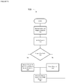
- FIG. 5 is a simplified flow diagram of a method for mapping, in accordance with various embodiments.
- FIG. 6 is a simplified flow diagram of a method for receiving an outbound message transmission request, according to some embodiments.
- FIG. 7 is a simplified flow diagram of a method for receiving an inbound message, according to some embodiments.
- FIG. 8 is a simplified flow diagram of a method for caching DNS requests, according to various embodiments.
- FIG. 9 is a simplified block diagram of a network, in accordance with some embodiments.
- FIG. 10 is a simplified block diagram of a network, in accordance with various embodiments.
- FIG. 11 is a simplified block diagram of a network, according to some embodiments.
- FIG. 12 is a simplified block diagram of a computing system, in accordance with some embodiments.
- FIG. 1 illustrates a simplified block diagram of an Internet Protocol (IP) network 100 .
- IP network 100 devices on a local network, called Hosts 110 , can be connected to one another using an IP switch or hub, Switch 120 .
- IP switch 120 For example, several switches may be connected to each other, serving as a single logical switch, even if physically distinct.
- Hosts 110 can communicate with one another directly by exchanging packets of data, delivered over Switch 120 .
- Hosts 110 can communicate with one another over switch 120 using link layer protocols.
- Hosts 110 (or more precisely, each network interface of a host) are identified at the link layer using link layer addresses.
- link-layer addresses such as Media Access Control (MAC) addresses are used to deliver the packets from one host to another.
- MAC Media Access Control
- applications can use Internet Protocol (IP) addresses to identify other hosts of Hosts 110 and communicate with them.
- IP Internet Protocol
- users of an application may identify a destination either by a host name (10.example.com) or an IP address (192.168.1.1).
- ARP Internet Engineering Task Force (IETF) Address Resolution Protocol
- both host A and host B are each one of the Hosts 110 .
- host A can find host B's link level address (e.g., MAC address) to deliver the packet over Switch 120 , which operates at the link level.
- Host A broadcasts a request to the rest of Hosts 110 connected to the Switch 120 , asking which host is associated with the IP address of host B. This is referred to as an ARP broadcast.
- host B with the requested IP address responds, providing its MAC address to host A.
- Host A equipped with host B's MAC address, may now send the packet to host B, over Switch 120 using link level protocols.
- any other Hosts 110 connected to the switch will also see the request from host A to identify which host is associated with host B's IP address.
- any mappings seen in this case, the mapping of host B's IP address to host B's MAC address
- ARP table entries have a time to live, eventually expiring.
- This process can be used to deliver packets to other Hosts 110 on the local network. That is, to other machines connected to Switch 120 .
- hosts that are on a common local network connected to the same switch
- the space or range of valid IP addresses within the local network is referred to as a subnet.
- All hosts on the subnet can have an IP address within the range of the subnet.
- Hosts are each issued an IP address and a network mask, either when configured or at the time they boot, for example, using a protocol called Dynamic Host Configuration Protocol (DHCP).
- DHCP Dynamic Host Configuration Protocol
- the combination of an IP address and netmask allows each host to identify the range of local network addresses (e.g., hosts on the local subnet). Given a destination IP address, a host may easily then determine if the destination address is on the same subnet and thus can be reached locally using the mechanism just described.
- the messages cannot be delivered using the mechanism described earlier only. Instead, the packets can be delivered out of the local network, to the broader network (e.g., the Internet), where higher level protocols (the IP protocol) can deliver the packet to the destination.
- the broader network e.g., the Internet
- the message can be sent over Network 140 (e.g., the Internet), via Gateway 150 .
- Network 140 e.g., the Internet
- Gateway 150 the IP address of Gateway 150 has also been made available to Hosts 110 earlier, either by configuration or via DHCP at boot time.
- Host A examines the packet, and notes (via a combination of its own IP address and the netmask) that the IP address of Remote Destination 130 is not part of the local subnet and cannot be reached directly over local Switch 120 .
- the host A can use Gateway 150 to send the packet out over the broader Network.
- Gateway 150 (which can be a special instance of a Host) responds, providing its own Link-level (MAC) address, and host A sends the packet to the Gateway using the provided MAC address, via the local Switch.
- MAC Link-level
- the packet can then be delivered over the broader Network 140 after being delivered there by Gateway 150 .
- the IP address of Remote Destination 130 is used to eventually deliver the packet to the local network where Remote Destination is located.
- Link-level addresses are again used between various devices in the Network (at each hop) to deliver the packet, and used by the gateway (not depicted in FIG. 1 ) at the remote location to deliver the packet to Remote Destination 130 .
- IP addresses can be resolved or translated into an IP address at the time the device (host) wishes to connect.
- DNS Domain Name System
- DNS IETF's Domain Name System
- the IP address of the name server like the IP address, netmask, and Gateway 150 address, is either preconfigured or obtained via DHCP at boot time.
- DNS servers may be on the local network or remote (in which case the requests will be sent via the Gateway).
- the name server is sent the hostname of the host, and returns the IP address (or an error if the name cannot be located) corresponding to the host.
- This IP address can then be used to request a MAC address corresponding to the host using ARP (for local addresses) or to forward a message to Remote Destination 130 via Gateway 150 .
- ARP for local addresses
- Gateway 150 The process of translating a human-readable hostname to an IP address is referred to as resolving the address.
- Hosts 110 on the network may be preconfigured with the important network information needed to enable IP connectivity (e.g., IP address, netmask, gateway IP address, DNS server IP address, and the like), or may use the IETF's Dynamic Host Configuration Protocol (DHCP).
- IP connectivity e.g., IP address, netmask, gateway IP address, DNS server IP address, and the like
- DHCP Dynamic Host Configuration Protocol
- IPv4 is as follows.
- IPv6 can work in an analogous manner, with some differences. These differences are not described here for brevity.
- a host (of Hosts 110 ) using DHCP connects to a new network (e.g., to a network for the first time), it attempts to obtain an address for itself and other network parameters by sending a DHCP DISCOVER message to the IP address 255.255.255.255, which is delivered to all the other hosts (of Hosts 110 ) on the local subnet.
- the goal is to locate a DHCP server, which can service the request for an IP address and supporting information.
- one or more hosts which can act as DHCP servers operating on the network, may offer a lease of an IP address to be used for a predefined period of time. If there are multiple DHCP servers, more than one may offer up an IP address to be used in a DHCP OFFER.
- the above exchange provides the host (of Hosts 110 ) with other information needed along with the IP address, for example netmask, gateway, and DNS server addresses.
- the DHCP server can be incorporated in the router and/or Wi-Fi access point (e.g., incorporated with a cable, Digital Subscriber Line (DSL), and the like modem).
- DSL Digital Subscriber Line
- ARP poisoning or ARP spoofing is used for attacks from nefarious actors, but as described herein can also be used to add useful features to network devices.
- a host seeing a response to an ARP request—even one it did not initiate—will add an entry mapping to IP address to MAC address information provided in the response.
- This mechanism is important, as in many cases IP addresses are reused. For example, on a wireless network at a coffee shop or other public location, a fixed number of IP addresses are available, and are allocated (e.g., using DHCP) to machines as they join the network. As machines leave, the leases of an IP address provided by the DHCP server expire, and the addresses are given the other machines.
- MAC link-level
- a spoofing host (of Hosts 110 ) on the network may broadcast unsolicited ARP responses, indicating that their MAC address is associated with a particular IP address, even if they are not configured to use that address and did not receive the address from the DHCP server. All Hosts seeing the unsolicited ARP response (can and most likely do) update their ARP table with this newly asserted mapping, as they have no way of knowing who is the “legitimate” holder of the IP address.
- the spoofing host (of Hosts 110 ) sends unsolicited responses at regular intervals, as well as whenever a conflicting response might be seen (to replace it)
- the spoofing host (and/or another host of Hosts 110 collaborating with the spoofing host) may effectively steal an IP address, forcing all traffic (e.g., data packets) intended for that address to be delivered to the spoofing host (and/or collaborating host) instead.
- This attack may be used to impersonate any host (of Hosts 110 ), including the Gateway 150 .
- Having a secondary network available provides numerous advantages to an end user. Failures of the primary network may have results that range from inconvenient (e.g., losing a video game or not being able to watch an online video) to life-threatening (e.g., loss of alarm system connectivity during a robbery or loss of contact with a medical device requiring constant monitoring).
- inconvenient e.g., losing a video game or not being able to watch an online video
- life-threatening e.g., loss of alarm system connectivity during a robbery or loss of contact with a medical device requiring constant monitoring.
- the ability to switch from a primary network to one or more secondary network(s) when the primary network fails and/or degrades is highly useful.
- metrics such as Quality of Service (QoS) metrics, total packet loss rates, network latency measurements, and other approaches may be used to determine when a network has degraded to the point that it is no longer adequate for a particular use. In the case of such degradation, or complete failure, some or all traffic may be moved to a secondary network.
- QoS Quality of Service
- Connection of customer devices to the secondary network may not be straight forward.
- the topology of the network that is, the way that the customer devices and the devices providing access to the primary and secondary network are arranged, can cause problems with access of the secondary network for some or all devices on the network.
- traffic may optionally be directed over various combinations and permutations of the primary and secondary networks.
- the capture may be used to duplicate all traffic over one or more secondary network(s) for reliability; to send redundant data (other than full duplication, e.g., packets containing redundant or error correcting information) over one or more secondary network(s); and/or to break the data into multiple streams, delivering only some of the traffic over each connection (e.g. “striping” of data, for example for security or reliability purposes).
- all data is described as being routed over either the primary or a secondary network, but mechanisms using multiple secondary networks; mechanisms duplicating the data over multiple networks; mechanisms striping the data over multiple networks; mechanisms extracting redundant information and delivering the redundant data over multiple networks; etc. may be additionally and/or alternatively performed.
- a secondary network is available and those where it is not, being able to capture all traffic—even traffic that not would not flow through a particular network device normally—is desirable to facilitate packet marking and may be performed in some embodiments. For example, it may be desirable to mark packets for special treatment as they are delivered across the network to Remote Destination 130 .
- An interactive communications provider or streaming media provider may want to preferentially mark their packets for higher priority routing (e.g., DiffServ or other QoS packet marking), and the ability to capture all packets and enforce marking is desirable. Note that it may be desirable to detect and remove markings from incorrectly (or nefariously) marked packets as well as to mark them.
- FIG. 2 illustrates a block diagram for network 200 connecting a customer (consumer or enterprise) to a Service Provider 220 .
- the customer connects to the services of Service Provider 220 and/or other services available over the Internet using Customer Devices 201 and/or Provider Hub Customer Devices 250 .
- Customer Devices 201 and/or Provider Hub Customer Devices 250 include computers, tablets, smartphones, or other consumer devices.
- the customer has both a Customer Router 210 and a Provider Hub 211 installed, for example, at a residence/home.
- Both Provider Hub 211 and Customer Router 210 can produce/control home networks to which Customer Devices 201 and/or Provider Hub Customer Devices 250 may connect.
- the home networks produced may take several forms, including wired Ethernet networks, Wireless (Wi-Fi) networks, DECT networks, ZigBee networks, Bluetooth networks, or other network types.
- the distinction between Customer Devices 201 and Provider Hub Customer Devices 250 relates to which of Customer Router 210 and Provider Hub 211 they are connected to.
- Customer Router 210 can be a home router device, which is used to allow multiple devices to access a network connection provided to the customer's Internet service provider (ISP). Customer Router 210 can provide access internally using one or more network technologies (e.g., wired Ethernet, Wi-Fi, etc.), and can also provide other capabilities such as firewall, network address translation (NAT), filtering, security capabilities, etc. Devices which connect to Customer Router 210 are here referred to as Customer Devices 201 . Network services are provided to Customer Devices 201 via Customer Router. In this example topology, the Customer Router itself is then connected to Provider Hub 211 , which provides network services to the Customer Router 210 .
- Provider Hub 211 provides network services to the Customer Router 210 .
- Provider Hub 211 can be provided and/or managed by Service Provider 220 .
- Provider Hub 211 can provide access to services offered by Service Provider 220 , for example by the consumer directly interacting with the device, and/or via one or more of the Customer Devices 201 and/or Provider Hub Customer Devices 250 connected to Provider Hub 211 .
- Devices connected directly to Provider Hub 211 rather than to the Customer Router 210 (and then on to Provider Hub), are referred to as Provider Hub Customer Devices 250 .
- Service Provider 220 offers communications services (e.g., telephony, video services, and the like), and Provider Hub 211 enables communications devices (e.g., telephone handsets, video devices, network devices, etc.) on the premises (e.g., in or near the residence/home) to connect to the service provided by Service Provider 220 .
- communications devices e.g., telephone handsets, video devices, network devices, etc.
- Provider Hub 211 may have connections to allow analog telephone devices, and/or DECT wireless telephone devices in the premises (e.g., as another instance of Provider Hub Customer Devices 250 ) to connect to and use the services of Service Provider 220 .
- Provider Hub 211 can include at least some of the capabilities of Customer Router 210 , such as facilitating network access over one or more access technologies, providing security and/or firewall services, etc. Because Provider Hub 211 can provide many or all the services provided by Customer Router 210 , in some embodiments the customer router may not be needed and Provider Hub 211 instead provides these services for all Customer Devices 201 . In such instances, all consumer devices are Provider Hub Customer Devices 250 .
- Access to Internet 232 for the end user can be over Access Network(s) 230 , via Access Device(s) 231 .
- Access Network(s) 230 may be a cable, fiber, DSL, wireless, Wi-Max, and the like, accessed via an Access Device(s) 231 , which may be cable modem, fiber modem, wireless router, and the like.
- Secondary Access Network(s) 241 accessed via Secondary Access Device(s) 240 , can be provided.
- Secondary Access Network(s) 241 may be a second network of the same type (e.g., a second cable modem), but may also be a connection over a different network (e.g., different network technology and/or ISP).
- the primary network e.g., Access Network 230
- secondary network e.g., Secondary Access Network(s) 241
- is a wireless backup network e.g., 4G, WiMax, and the like.
- the primary network e.g., Access Network 230
- secondary network e.g., Secondary Access Network(s) 241
- the primary network is a wired network (e.g., cable, DSL, fiber, and the like)
- secondary network e.g., Secondary Access Network(s) 241
- wired backup network e.g., cable, DSL, fiber, and the like
- Other Destinations 260 may also be reached for other service.
- Provider Hub 211 is connected to one or more Access Network(s) 230 and/or Secondary Access Network(s) 241 to reach the Internet 232 (and on to Service Provider 220 or Other Destination 260 ).
- one or more Access Device(s) 231 and/or Secondary Access Device(s) 240 may be between the provider hub and the access network(s).
- the network service for the customer is provided by a cable company ISP, and the access device takes the form of a cable modem.
- the access network is a cellular network, for example an LTE network, and the access device is a modem to connect to the cellular network.
- the access device is a consumer device featuring a network connection which it can share with other devices. For example a mobile phone may share its broadband connection with provider hub and/or consumer router as a network connection (e.g., via a “hotspot”).
- features/functions of Access Device(s) 231 and/or Secondary Access Device(s) 240 may be integrated/included in Provider Hub 211 (and/or Customer Router 210 , if connected directly to the access networks).
- various combinations and permutations of stand-alone access device and similar technologies can be integrated into Provider Hub 211 and/or Customer Router 210 (e.g., a stand-alone access device in the form of a cable modem connected to the provider hub, as well as integrated hardware allowing access to a wireless LTE network included in the provider hub).
- Customer Router 210 is connected to Access Network(s) 230 and Secondary Access Network(s) 241 via Provider Hub 211 . That is, the customer router is said to be “behind” or “inside” of the provider hub relative to the access network. Customer Router 210 (and Customer Devices 201 attached to the Customer Router) may access the network via Provider Hub 211 , said to be “outside” or “in front” of the Customer Router. Other architectures can be used and are discussed further below.
- Provider Hub 211 can control and direct all traffic (e.g., data packets)—whether from Customer Devices 201 attached to Customer Router 210 or from Provider Hub Customer Devices 250 .
- Traffic from Provider Hub Customer Devices 201 can flow directly to Provider Hub 211 , and Provider Hub 211 may direct that traffic over the Access Network(s) 230 and/or Secondary Access Network(s) 241 .
- Provider Hub 211 since traffic from Customer Devices 201 flows to Customer Router 210 , which then flows to Provider Hub, all traffic from these devices may be monitored and controlled by Provider Hub 211 , and directed to either the Primary Access Network 230 or Secondary Access Network 241 (or a combination (e.g., duplication, striping, redundant data) of both).
- Provider Hub 211 When the optional Customer Router is not present, all devices are Provider Hub Customer Devices 250 , and traffic flows through Provider Hub 211 .
- Provider Hub 211 also provides NAT capabilities, meaning that devices “behind” (that is, toward the customer side of) Provider Hub 211 typically will have a private, internal address that does not change when switching from Primary Access Network 230 to Secondary Access Network 241 .
- Traffic flows may be monitored, either by the Provider Hub 211 or by Service Provider 220 .
- Service Provider 220 When failure or degradation of the Access Network(s) 230 is observed, some or all traffic can be moved to Secondary Access Network(s) 241 . This determination may be made by either Provider Hub and/or by Service Provider.
- some or all traffic may be moved back from Secondary Access Network(s) 241 to Primary Access Networks(s) 230 when it is determined (e.g., by Service Provider 220 and/or Provider Hub 211 ) that network conditions on the Primary Access Network(s) 230 have improved.
- the streams are maintained and managed by Provider Hub 211 , with the customer device (of Customer Devices 250 ) having a stream between itself and the Provider Hub, rather than all the way to the stream destination.
- TCP Transmission Control Protocol
- the customer device of Customer Devices 250
- the Provider Hub rather than all the way to the stream destination.
- FIG. 3 is a simplified block diagram 300 showing a stream-oriented connection between a customer device, here shown as Stream Customer Device 310 (which could be either a Customer Device 210 or a Provider Hub Customer Device 250 ), and Destination 320 .
- Destination 320 may be Service Provider 220 or any Other Destination 260 Stream Customer Device 310 needs to connect to.
- the connections can be managed by Provider Hub 211 .
- Access Device(s) 231 and Secondary Access Device(s) 240 have been omitted here for clarity.
- Stream Customer Device 310 can establish a connection over a stream to Destination 320 . Because all traffic flows through Provider Hub 211 , the Provider Hub can intercept and manage this connection. For example, this is accomplished by simply providing an address for Provider Hub 211 to Stream Customer Device 310 to reach destination 320 . By way of further non-limiting example, this is accomplished by providing DNS name resolution to Stream Customer Device 310 that provides Provider Hub's 211 internal address when resolving the URL for Destination 320 . By way of additional example, Stream Customer Device is pre-provisioned with Provider Hub's internal address to reach the Destination.
- Stream Customer Device 310 attempts to establish the connection using Destination 320 's address as normal, but because Provider Hub 211 is in the path of all traffic in this architecture, the traffic is intercepted by Provider Hub, without needing to provide Provider Hub's address to Stream Customer Device 310 .
- the information contained in the messages intended for Destination 320 may be examined by Provider Hub 211 , for example by use of deep packet inspection (DPI), and rather than forward this traffic to Destination 320 and allow the connection to be established between Destination 320 and Stream Customer Device 310 ,
- Provider Hub 211 acts as an endpoint and establishes the stream-oriented connection, Local Stream Connection 330 , between Provider Hub 211 and Stream Customer Device 310 .
- Stream Customer Device 310 believes it is connecting directly to the public address of Destination 320 .
- Provider Hub 211 may intercept earlier messages from Stream Customer Device 310 establishing encrypted connections, requesting certificates from public locations, etc., and in each case substitute its own connections or certificates as appropriate.
- Provider Hub 211 is provided by and operated by Service Provider 220 (an (exemplary) embodiment of Destination 320 ), Provider Hub 211 is provided with appropriate credentials to authenticate the communication.
- Provider Hub can also open Primary Stream Connection 340 between itself and Destination 320 , over Access Network(s) 230 and Internet 232 .
- a Secondary Stream Connection 350 (and possibly even further parallel streams) over Secondary Access Network(s) 241 and Internet 232 may also be opened at this time. Traffic between Stream Customer Device 310 and Destination 320 is delivered over one or more of these connections, with Stream Customer Device 310 believing Local Stream Connection 330 is the actual connection to the Destination 320 , and Destination 320 believing that Primary Stream Connection 340 (and/or Secondary Stream Connection 350 ) is the actual connection to the Stream Customer Device.
- Decisions as to whether delivery over the Primary Stream Connection 340 or Secondary Stream Connection 350 is appropriate may be made by Provider Hub 211 , other customer devices (e.g., Customer Devices 201 , Customer Router 210 , Provider Hub Customer Devices 250 ) or Destination 320 depending on network quality, cost, etc.
- Provider Hub 211 other customer devices (e.g., Customer Devices 201 , Customer Router 210 , Provider Hub Customer Devices 250 ) or Destination 320 depending on network quality, cost, etc.
- Provider Hub 211 directs traffic over Primary Stream Connection 340 and/or Secondary Stream Connection 350 such as indicated by preconfigured options.
- these options specify conditions under which the Primary Stream Connection is considered failed or degraded, and under these conditions, traffic is moved to Secondary Stream Connection 350 .
- Traffic may be moved dynamically between the two stream connections as network conditions warrant.
- cost, delay, utilization, utilization within a billing period e.g., “how much of the data plan has been used?”
- data may be simultaneously sent over a combination of the primary and secondary networks (e.g., duplication, striping, redundant data).
- Provider Hub 211 can terminate Primary Stream Connection 340 , and establish Secondary Stream Connection 350 dynamically at the time that the network failure, degradation, or other reason (e.g. cost) indicates a need to switch to secondary network (e.g., Secondary Access Network 241 ). In some cases, this may be transparent to Stream Customer Device 310 , which continues to send traffic over Local Stream Connection 330 .
- Provider Hub 211 may buffer traffic as needed.
- the protocol or application may need Provider Hub to signal Stream Customer Device indicating that Local Stream Connection 330 has failed or otherwise needs to be reestablished, terminate the Local Stream Connection, and/or in some other way force closure and/or reestablishment of Local Stream Connection 330 , then re-establish over the secondary network (e.g., Secondary Access Network 241 ).
- the secondary network e.g., Secondary Access Network 241
- Provider Hub 211 can be NATing traffic
- Stream Customer Device 310 can have a private address that does not change regardless of traffic flowing over the primary (e.g., Access Network 230 ) or secondary network (e.g., Secondary Access Network 241 ), because Local Stream Connection 330 is between (only) Stream Customer Device 310 and Provider Hub 211 .
- NAT services may not be needed, and both Stream Customer Device 310 and Provider Hub 211 may have public addresses.
- Provider Hub 211 does not itself become involved in the stream connections, but can manipulate the underlying network to direct traffic either over the primary or secondary network.
- FIG. 4 shows another network 400 approach, in which the stream connection between Stream Customer Device 310 and Destination 320 is established end-to-end, without intervention by Provider Hub 211 .
- Local Stream Connection 310 may not be used. Rather, when Stream Customer Device 310 wishes to connect to Destination 320 , an end-to-end connection 440 can be established over Access Network(s) 230 and Internet 232 .
- Provider Hub 211 can terminate the connection, such as by disconnecting access to (primary) Access Network(s) and/or by a more sophisticated means.
- Provider Hub 211 can examine the traffic (e.g., data packets) in Primary Stream Connection 340 and injecting traffic such as reset packets, and/or by selectively dropping packets that will cause mechanisms in the streaming protocol to terminate the connection.
- the Stream Customer Device 310 and/or Destination 320 will (eventually) attempt to reestablish the network connection.
- Provider Hub 211 can use the secondary network (e.g., Secondary Access Network 241 ) instead, resulting in Secondary Stream Connection 450 being established.
- Secondary Access Network 241 e.g., Secondary Access Network 241
- Stream Customer Device 310 will notice no difference in the outbound connection.
- the public IP address that Destination 320 observes traffic originating from will be different, and will be an address on Secondary Access Network(s) 241 , rather than Access Network(s) 230 , allowing Destination 320 to observe the connection as being distinct.
- Provider Hub 211 maintains a set of mappings of internal IP addresses to use for mapping requests to the secondary network. These internal IP addresses are typically, but are not required to be, in a different address space (e.g., subnet) than those used to provide traditional NAT service to devices behind the Provider Hub 211 .
- customer devices e.g., one of either Customer Devices 201 or Provider Hub Devices 250
- Provider Hub 211 may be in a particular reserved address space (e.g., 192.168.0.0 with a netmask of 255.255.255.0-192.168.0.0/24), while the internal IP addresses used for mappings may be a different network (e.g., 10.0.0.0 with a netmask of 255.0.0.0-10.0.0.0/8).
- the addresses reserved for link local connections may be used for this purpose, although there is risk that other protocols may use these addresses.
- Provider Hub 211 can keep track of mappings using these internal IP addresses.
- the mappings may be defined by hard coding, by Provider Hub 211 , an external service (e.g., Service Provider 220 ), and/or internal customer device (e.g., Provider Hub 211 , Customer Router 210 , Customer Devices 201 , and/or Provider Hub Customer Devices 250 ) requesting a mapping to enable use of the outside address via Secondary Access Network(s) 241 .
- Provider Hub 211 external service (e.g., Service Provider 220 ), or customer device (e.g., one of either Customer Devices 201 or Provider Hub Devices 250 ) has noticed a network failure, network degradation, and/or cost/utilization issue that prompts a switch to the secondary network.
- This can be initiated by prompting the customer device to use the secondary network (e.g., Secondary Access Network 241 ) directly (by contacting the destination at the mapped local address, rather than the true public address), or by provisioning or configuring the device with the mapped secondary address as a “backup server,” which can be used when connections over the (primary) Access Network(s) 230 fails.
- secondary network e.g., Secondary Access Network 241
- Provider Hub 211 may (e.g., using techniques such as DPI or similar approaches) manipulate the data in Primary Stream Connection 440 and Secondary Stream Connection 450 (not depicted in FIG. 4 ).
- Stream Customer Device 310 sends information normally, to the primary server, and traffic is directed over Primary Stream Connection 440 .
- Provider Hub may extract information from that stream, and direct some or all of it over Secondary Stream Connection 450 . This can include deciding to send all information over one or the other of Access Network 230 or Secondary Access Network 241 , striping information across both connections, duplicating information across both networks, sending redundant information across one or more networks, etc.
- FIG. 5 illustrates process 500 for mapping, requested by Provider Hub 211 .
- the request to create a mapping can be received.
- the request can be verified. Verification can include checking that the requestor is allowed to make the request, the request is validly formed, and that there are private IP addresses still available to be mapped from the pool.
- a new private IP address can be allocated and mapped to the public IP address at step 540 . If the request is invalid or cannot be met, the request can be rejected at step 550 .
- the process can return to waiting for new requests and moves to start at step 560 .
- process 500 can have Provider Hub 211 allocating the addresses, the allocation could also be controlled by Service Provider 220 , or by another centralized entity that manages the available pool of addresses. In this case, the mappings can then be passed to Provider Hub 211 (not shown in FIG. 5 ). Additionally, expiry of addresses after a period of disuse is not illustrated here for clarity, but can be included in process 500 .
- Error processing e.g., requests for invalid external addresses, for unmapped private addresses, and the like
- Error processing is not shown in FIG. 6 for simplicity. Additionally, translations of internal addresses as part of the functioning of NAT capabilities, may be performed, but are not shown for clarity.
- packets are duplicated across both networks (not shown in FIG. 6 ). For example, the original packet is sent as well as creating a duplicate to send over the other network. Similarly, packets may be striped across the networks, or redundancy information generated and sent across the other network.
- Inbound response messages from the destination can also have their headers re-written, to make them appear to originate from the mapped private address, rather than the mapped public address.
- Mappings maintained by the provider hub e.g., Provider Hub 211
- XXX.XXX.XXXX is a public address. All inbound messages can be examined, and those arriving on Secondary Access Network(s) 241 with source addresses matching a right hand side of a mapping are rewritten, replacing the source address with the left hand side.
- FIG. 7 illustrates method 700 for receiving an inbound message (e.g., by Provider Hub 211 ).
- an inbound packet is received from Secondary Access Network(s) 241 .
- the packet can be examined to determine if the source IP address of the packet is an address that is currently used as a right hand side in a maintained mapping.
- the message can either be forwarded normally to an internal destination (for example, using the default NAT mappings), or dropped, for example in a scenario where incoming messages are not expected from this destination over the secondary network.
- Process 700 can continue at step 770 .
- processing can move to step 740 .
- the mapped private address (left hand side) associated with the public address (right hand side) can be retrieved.
- source headers can be rewritten to use this private address obtained at step 740 . Additionally, further rewriting of other portions of the packet, for example application level headers, can be performed at this step.
- the packet (with translated headers) can be forwarded to the destination. Process 700 can continue to step 770 , where the Provider Hub can return to waiting for new packets, moving to start.
- Error processing e.g., requests from invalid external addresses, for unmapped private addresses, and the like
- Error processing is not shown in FIG. 7 for simplicity. Additionally, translations of internal addresses as part of the functioning of NAT capabilities, may be performed, but are not shown for clarity.
- packets are duplicated, striped, or redundant information conveyed across both networks.
- the packets received may require processing to combine into a single packet stream before being delivered to the host.
- the (mapped) private addresses can be employed when using the (primary) Access Network(s), and the public addresses can be employed when using the Secondary Access Network(s), without loss of generality.
- a customer device e.g., one of either Customer Devices 201 or Provider Hub Devices 250
- a destination e.g., one of either Service Provider 220 or Other Destination 260 . This can be either via a stream-oriented or non-stream-oriented protocol.
- the customer device When the customer device (e.g., one of either Customer Devices 201 or Provider Hub Devices 250 ) wishes to reach the destination, the customer device may have the destination (e.g., one of either Service Provider 220 or Other Destination 260 ) in the form of an IP address, in which case this may not apply.
- the destination e.g., one of either Service Provider 220 or Other Destination 260
- the hostname (or hostname portion of the URL) should be resolved or translated into an IP address using DNS, as described earlier.
- the DNS server provided to the customer device can be controlled by Service Provider 220 .
- the customer device e.g., one of either Customer Devices 201 or Provider Hub Devices 250
- the IP address of an external DNS server is controlled (directly or indirectly) by Service Provider 220 .
- the customer device is hard coded with, or when a customer device boots and receives an IP address provided using DHCP, the IP address of Provider Hub 211 is given and Provider Hub 211 acts as the DNS server.
- Provider Hub 211 can incorporate a DNS server and/or proxy DNS requests to Service Provider 220 and/or a service on behalf of Service Provider 220 .
- Access Network(s) 230 When hostnames are resolved, the condition (or cost or other factors) of Access Network(s) 230 is considered by Service Provider 220 and/or Provider Hub 211 . If the (primary) Access Network(s) (e.g., Primary Access Network(s) 230 ) connectivity, connection quality, cost, etc. are determined to be adequate, the name resolution returns the actual IP address for the destination. When the traffic for this address reaches Provider Hub 211 , it is delivered as normal (e.g., without altering the data packet header), over Access Network(s) 230 .
- Primary Access Network(s) 230 e.g., Primary Access Network(s) 230
- a different, private space address can be returned.
- private space addresses as described in Request for Comment 1918 from the Internet Engineering Task Force (IETF) (RFC1918) can be used.
- This address space can be distinct from the range used for internal devices (e.g., customer devices) by the NAT built into Provider Hub 211 .
- a mapping between the actual (public) address of the destination and this new (private) address provided to the device can be maintained by Provider Hub 211 .
- a private address e.g. 10.0.33.44 is provided to the device instead, and the mapping XXX.XXX.XXX.XXX ⁇ 10.0.33.44 is maintained by Provider Hub 211 as discussed earlier.
- Provider Hub 211 When a request to connect to the (private) destination address (e.g. 10.0.33.44) is made by a device (e.g., of Customer Devices 201 and/or Provider Hub Devices 250 ), Provider Hub 211 , recognizing that this address is within the private space reserved for this purpose, will retrieve the actual (public) address (e.g. XXX.XXX.XXX.XXX) and redirect traffic to this destination over Secondary Access Network 241 , translating packet headers in the same way as discussed earlier.
- a device e.g., of Customer Devices 201 and/or Provider Hub Devices 250
- Provider Hub 211 When a request to connect to the (private) destination address (e.g. 10.0.33.44) is made by a device (e.g., of Customer Devices 201 and/or Provider Hub Devices 250 ), Provider Hub 211 , recognizing that this address is within the private space reserved for this purpose, will retrieve the actual (public) address (e.g.
- packet duplication techniques using both networks may be used, in addition to simply determining the best network and sending traffic over that connection.
- DNS address resolutions can be cached by the client (e.g., Customer Devices 201 and/or Provider Hub Devices 250 ) making the DNS resolution request.
- responses include a time to live, or TTL.
- TTL time to live
- the addresses provided can be changed whenever the network conditions (e.g., quality, connectivity, cost, etc.) change, the TTL returned should by necessity be very short. For example, this value is set to 60 seconds. If the device wishes to connect to the destination again after 60 seconds, the process can be repeated, allowing for a different address (using either the primary or secondary network) to be returned.
- FIG. 8 illustrates method 800 for caching DNS requests.
- method 800 is performed by the DNS server entity (e.g., Provider Hub 211 , a DNS server controlled by/operating on behalf of Service Provider 220 , and the like).
- the entity processing the DNS request can receive a DNS request from a device (e.g., Customer Devices 201 and/or Provider Hub Devices 250 ).
- the name resolution is performed as normal, identifying the public address corresponding to the hostname in the DNS request.
- the entity processing the DNS request can determine if the primary network (e.g., Primary Access Network(s) 230 ) should be used.
- the outcome may be because the primary network is degraded or non-functional, but may also be based on cost, utilization (e.g., how much of a monthly bandwidth allocation has been used) or other metrics.
- step 830 If it is determined the primary network (e.g., Primary Access Network(s) 230 ) should be used at step 830 , then flow can continue at step 840 , where the public IP address identified at step 820 is returned to the device (e.g., Customer Devices 201 and/or Provider Hub Devices 250 ) requesting the name resolution. Flow can continue at step 880 .
- the primary network e.g., Primary Access Network(s) 230
- the public IP address identified at step 820 is returned to the device (e.g., Customer Devices 201 and/or Provider Hub Devices 250 ) requesting the name resolution.
- Flow can continue at step 880 .
- step 830 If it is determined the primary network (e.g., Primary Access Network(s) 230 ) should not be used (or that the primary network will be used in combination with the secondary network, for example using duplication, striping, and/or creation of redundant packets) at step 830 , then flow can continue at step 850 , where a private IP address is allocated, and the public IP address identified at step 820 is mapped to the allocated private address.
- the mapping can be forwarded to Provider Hub 211 . If Provider Hub 211 is serving as the DNS server and/or relaying the DNS requests, this step may be not be needed.
- the private address can be returned to the device (e.g., Customer Devices 201 and/or Provider Hub Devices 250 ). Flow can then continue at step 880 .
- method 800 can return to waiting for the next DNS request, and flow returns to the beginning of the process.
- allocation can also be performed by Provider Hub 211 , Service Provider 220 , another centralized entity that manages the available pool of addresses, and the like. Although expiry of addresses after a period of disuse is not illustrated here for clarity, it can be included in method 800 .
- the Provider Hub 211 can maintain the list of address translations and translates messages send to mapped private addresses to public addresses before sending them over Secondary Access Network 241 (see FIG. 6 ). Similarly, incoming messages received over the Secondary Access Network 241 from destinations forming the right hand side of mappings for private mapped addresses have appropriate source addresses translated before being sent to private devices (see FIG. 7 ).
- FIG. 9 depicts another network 900 in which Provider Hub 211 is not in the direct path of all outbound traffic.
- (Primary) Access Network(s) 230 can be accessed via Customer Router 210 , which is connected to the Access Network.
- Customer Router 210 can be the primary gateway device (e.g., Gateway 150 from FIG. 1 ). Traffic originating from Customer Devices 201 and directed to external addresses (e.g., to Service Provider 220 and/or Other Destination 260 ) may not flow through Provider Hub 211 in the architecture of network 900 . Additionally, if the Secondary Access Network 241 is needed, for example because the (primary) access network has failed, Customer Devices 201 may not have access to the Secondary Network without either (explicit) cooperation from Customer Router or using one of the techniques described below.
- Provider Hub Customer Devices 250 can be connected to Provider Hub 211 , which can serve as the gateway for those devices.
- Provider Hub relays traffic from Provider Hub Customer Devices to Customer Router 210 on their behalf, over Link(s) 910 .
- traffic can also be sent over Secondary Access Network 240 (or in combination with the (primary) Access Network), connected to Provider Hub.
- Customer Router 210 devices devices connected to its internal interfaces (e.g., Customer Devices 201 and Provider Hub 211 ) can be connected by a link-layer switch. As such, all of these devices can share an ARP broadcast space and see ARP requests from one another. In some cases, wireless devices connected to Customer Router can have a different ARP broadcast space than wired devices. In these instances, Provider Hub 211 can be connected with both wireless and wired connections (two instances of 910 ), enabling Provider Hub 211 to participate in both ARP broadcast spaces. If there are additional wireless and/or wired networks, for example multiple wireless networks, various wired technologies, etc., the Provider Hub 211 can maintain an instance of Link 910 to each of these networks, allowing access to all available ARP broadcast spaces.
- the Provider Hub 211 can maintain an instance of Link 910 to each of these networks, allowing access to all available ARP broadcast spaces.
- Customer Router serves as Gateway 150 ( FIG. 1 ) for Customer Devices 201 , and as a gateway for Provider Hub 211 (e.g., when the primary Access Network is functional), which itself serves as the first gateway for Provider Hub Customer Devices 250 , relaying their outbound traffic to Customer Router 210 and on to Access Network 230 .
- Provider Hub 211 and/or Service Provider 220 When a failure, degradation, cost reason, or other factor causes Provider Hub 211 and/or Service Provider 220 to determine that the (primary) Access Network(s) 230 is no longer functioning as desired, Provider Hub 211 will redirect traffic over Secondary Access Network(s) 241 (or a combination of primary and secondary networks). However, in the network configuration shown in FIG. 9 , (only) traffic originating from Provider Hub Customers Devices 250 will be directed over the Secondary Network. Provider Hub will discontinue sending traffic to Customer Router 210 for delivery to Access Network 230 , and will instead direct it over the Secondary Access Network(s) 241 .
- Provider Hub Customer Devices 250 may direct traffic over Secondary Access Network(s) 241 , including Provider Hub 211 transparently managing the connection, Provider Hub 211 using NAT-like translation and preconfigured addresses to relay traffic over Secondary Access Network(s) 241 , Provider Hub 211 providing DNS to Provider Hub Customer Devices 250 that provides private address to relay traffic, etc.
- Provider Hub 211 e.g., Provider Hub Customer Devices 250
- Secondary Access Network(s) 241 e.g., a combination of primary and secondary networks.
- ARP spoofing or poisoning is used by Provider Hub 211 in an architecture like network 900 in FIG. 9 to enable both Customer Devices 201 and Provider Hub Customer Devices 250 to access both (primary) Access Network 230 and Secondary Access Network 241 .
- Provider Hub 211 can act as the gateway for Provider Hub Customer Devices 250 , but Customer Router 210 can act as the gateway for Customer Devices 201 . However, Provider Hub can continue to be the gateway for Provider Hub Customer Devices and also take control of the link level network that Customer Devices 201 are connected to by using ARP spoofing.
- Provider Hub 211 can send unsolicited “spoofed” ARP responses over Link 910 , identifying its own MAC address as being the link layer address associated with the IP address Customer Devices 201 have configured for their gateway. When Customer Devices 201 see this response, they replace their entry for the gateway, previously mapping traffic to the link-level address for Customer Router 210 , with the link-level address of Provider Hub 211 . When this occurs, all external traffic from Customer Devices 201 will be delivered to Provider Hub 211 instead, which may then forward the traffic (“hairpin”) back to Customer Router 210 to be delivered over Access Network 230 , can deliver the traffic over Secondary Access Network 241 , or duplicate traffic over both links using duplication, striping, and/or redundant packet approaches.
- Provider Hub 211 can also listen on the shared ARP broadcast space for any ARP requests for the IP address associated with the default gateway. In addition to replying to these requests, Provider Hub monitors to ensure that if any other host (e.g., Customer Router 210 ) replies with their own MAC address, the Provider Hub immediately sends another (unsolicited) ARP response immediately after detecting such a response.
- any other host e.g., Customer Router 210
- the Provider Hub immediately sends another (unsolicited) ARP response immediately after detecting such a response.
- Provider Hub 211 can monitor the shared ARP space for broadcasts. If Customer Router 210 or any other host sends (unsolicited) ARP response broadcasts claiming the address of the gateway, Provider Hub will immediately send another unsolicited ARP response claiming the address of the gateway, to ensure that all traffic will continue to arrive at Provider Hub.
- Provider Hub 211 may have multiple Link(s) 910 , enabling it to access multiple ARP broadcast spaces, for example for wired and wireless networks.
- unsolicited ARP responses will be sent over each Link(s) 910 periodically, as well as immediately after any conflicting messages claiming the gateway address are sent by Customer Router 210 or any other device.
- source addresses e.g., link-layer/MAC, IP, application layer, the like, and combinations thereof
- source addresses e.g., link-layer/MAC, IP, application layer, the like, and combinations thereof
- This ensures return traffic is delivered to Provider Hub 211 when responses arrive. While not strictly required, this facilitates other actions (e.g., packet re-writing (e.g., headers), packet examination, etc.) that Provider Hub 211 may advantageously perform on the returning packets before sending to the ultimate destination.
- This can be needed if Customer Router 210 has filtering software that may detect and drop packets shown as originating from a switch link having a MAC address that is not currently associated with that switch link.
- Provider Hub 211 does not modify the source addresses (e.g., MAC, IP, and the like) before relaying traffic to Customer Router 210 for delivery over Access Network 230 . Response traffic will then be delivered directly to the source by Customer Router 210 .
- source addresses e.g., MAC, IP, and the like
- an internal DNS server is established, rather than use an external DNS server.
- ARP spoofing may again be used, but rather than attempting to impersonate the gateway as described above,
- Provider Hub 211 uses ARP spoofing to claim traffic intended for the internal DNS server.
- Some or all of the techniques described above for using ARP spoofing to capture traffic intended for the gateway can be leveraged to capture traffic intended for the local DNS server. Once this is accomplished, DNS traffic may be manipulated as discussed earlier in the provider Hub DNS Approach.
- IP address of the gateway and the DNS server are (likely to be) the same.
- ARP spoofing to capture IP address of the DNS server also captures the traffic that would (otherwise) be sent to the gateway. In that case, all traffic is captured and hairpinned, and the general ARP spoofing case above applies.
- Provider Hub 211 monitors the network for traffic from new Customer Devices 201 joining the network, in an attempt to intercept their DHCP requests and provide alternate results. This is performed (only) over Link(s) 910 —this may not be needed for Provider Hub Customer Devices 250 , traffic from which Provider Hub 211 already controls.
- Provider Hub 211 can use DHCP over Link 910 to obtain a valid IP address, subnet, gateway address, and DNS server address from Customer Router 210 . This allows Provider Hub 211 to send traffic out over Access Network 230 , as well as to identify the subnet being used by Customer Router 210 (e.g., determined based upon the address and netmask provided by Customer Router 210 in response to the Provider Hub's 211 DHCP request). This subnet is referred to as the Router Subnet here for clarity.
- Provider Hub 211 After obtaining an address, when Provider Hub 211 detects a DHCP request has been broadcast by a new Customer Device 201 , it (immediately) responds to the message with a DHCP OFFER, offering an IP address in a different private subnet (e.g., range of private addresses), which is referred to as the Hub Subnet here for clarity. This subnet is different from the one maintained by Customer Router 210 (the Router Subnet). When providing this DHCP offer, in addition to providing an address in a different subnet, Provider Hub 211 presents itself as the gateway to be used with that private address and subnet, and may also identify itself as the DNS server.
- a DHCP OFFER offering an IP address in a different private subnet (e.g., range of private addresses), which is referred to as the Hub Subnet here for clarity.
- This subnet is different from the one maintained by Customer Router 210 (the Router Subnet).
- Provider Hub 211 presents itself as the gateway to be used with
- Customer Device 201 If Customer Device 201 accepts the DHCP offer, Customer Device 201 now has an IP address on the Hub Subnet. Because Provider Hub 211 was presented as the gateway for this address, all outbound traffic from the new Customer Device 201 will be routed to Provider Hub, and may then be forwarded over Access Network(s) 230 via Customer Router 210 (optionally with re-written headers) or over Secondary Access Network(s) 241 .
- Provider Hub 211 By intercepting this DHCP traffic and providing alternate addresses to the Customer Device 201 , Provider Hub 211 has (in effect) created a virtual (VLAN; a broadcast domain that is partitioned and isolated in a computer network at the data link layer), but for a very novel purpose, enabling control of Customer Device(s) 201 traffic, including enabling the use of the Secondary Access Network 241 for devices not located behind Provider Hub.
- VLAN virtual
- Secondary Access Network 241 for devices not located behind Provider Hub.
- Provider Hub 211 rewrites the traffic (e.g., data packet headers), replacing Customer Device's 201 Hub Subnet address with Provider Hub's 211 own Router Subnet address.
- the messages (traffic or data packets) are then passed to Customer Router 210 to relay it on to Access Network 230 .
- Responses are returned to Provider Hub 211 , which rewrites the packets back to the Hub Subnet address for Customer Device 201 and passes the message to Customer Device 201 .
- This is a second layer of NAT translation, being performed within the same network, but for a unique purpose of capturing and forwarding traffic over a secondary network (when needed).
- Traffic e.g., data packets
- Service Device 201 may instead be routed over Secondary Access Network 241 (or may be directed over a combination of primary and secondary networks, using techniques such as duplication, striping, and/or the creation of redundant packets).
- a race condition may occur here. If Provider Hub 211 is unable to respond more quickly than Customer Router 210 (e.g., a home router) to DHCP requests, it is possible that Customer Router 210 , rather than Provider Hub's DHCP response will be accepted. To prevent this, Provider Hub 211 tries (is configured to) to respond as quickly as possible, particularly over wired connections in a switched medium, as is common on modern switched wired Ethernet. However, for shared connections (e.g., wired networks connected with a hub or wireless networks), another unique mechanism can be used.
- Provider Hub 211 watches for DHCP traffic over Link 910 , where Link 910 is to a shared media (e.g., a wireless or hub-based network).
- a shared media e.g., a wireless or hub-based network.
- Provider Hub 211 rather than responding to the message immediately, it instead sends “jam” messages for the underlying link-layer protocol.
- CSMA/CD carrier-sense multiple access with collision detection
- Provider Hub 211 immediately sends a DHCP OFFER as soon as it completes sending the jam message, while other senders, including the Customer Router 210 , will be waiting a random time for the jam condition to clear. This helps ensure that the DHCP OFFER from Provider hub is likely to be accepted by the Customer Device.
- Some Customer Devices 201 are designed to allow multiple servers to be used in a failover scenario.
- some Session Initiation Protocol (SIP) endpoints may be configured with a primary server as well as one or more secondary servers.
- IP Session Initiation Protocol
- Provider Hub 211 after obtaining an internal IP address from Customer Router 210 , communicates this internal IP address to Service Provider 220 , and Service Provider 220 and Provider Hub 211 cooperate to allocate a number of ports using Provider Hub's 211 internal address that are available.
- Customer Devices 201 communicating with Service Provider 220 are provided one of these internal address (of Provider Hub 211 ) and port pairs as a backup address for the application connecting to Service Provider.
- Service Provider 220 provides the internal address of Provider Hub 211 (obtained from Provider Hub) to Customer Devices 201 which are explicitly aware to use this as a backup address. Because this requires some awareness on the part of the Customer Device 201 (e.g., being programmed explicitly with the mapped address as a backup server), unlike other approaches described above, this solution may not be a solution for general access of all applications to the Secondary Access Network 241 .
- Customer Devices 201 send application traffic to the pre-agreed port on Provider Hub 211 .
- Provider Hub 211 forwards the traffic over Secondary Access Network 241 , rewriting response packets to appear to originate from itself if/when needed. Responses may be similarly rewritten to appear to originate from Provider Hub 211 . This is analogous to the process described in FIG. 6 and FIG. 7 .
- all traffic captured can be marked (and/or have its markings modified).
- the packets are examined to determine if they should be marked in some way to indicate preferential routing treatment. For example, it may be desirable to mark devices that are sending real-time streaming information for preferential treatment. This marking facilitates improved QoS processing by devices further down the network path. Standardized markings such as DiffServ DSCP fields may be used for this purpose, or other mechanisms may be defined.
- packets that have been marked, but should not be e.g., from applications marking themselves to try to improve application performance
- inbound packets may be marked or markings removed by the Provider Hub 211 for improved management by an internal network.
- Marking can be combined with delivery over one or more secondary network(s). That is, marked packets may then be delivered over the (primary) Access Network(s) 230 , over Secondary Access Network(s) 241 (if available), or over some combination of both networks, using replication techniques (e.g., duplication, striping, and/or creation of redundant information packets)
- replication techniques e.g., duplication, striping, and/or creation of redundant information packets
- Some of Customer Routers 210 can include capabilities allowing them to use a secondary network (e.g., Secondary Access Network 241 ) directly. In some cases, this is via a connection allowing a second network to plug in via Ethernet. In other cases it can be via Universal Serial Bus (USB), allowing a secondary Access Device 240 (e.g., a WiMax, 4G, and the like modem) to be connected to provide a second network connection.
- a secondary Access Device 240 e.g., a WiMax, 4G, and the like modem
- Provider Hub 211 is connected to Customer Router 210 not just with an internal Link 910 , but with an external link 1010 .
- This connection allows Provider Hub 211 to appear to the Customer Router 210 to be a secondary network connection, either over a network connection (e.g., wired Ethernet, WiFi, DECT, Blue Tooth, etc.) or a computer connector (e.g., USB, serial, firewire, etc.).
- Customer Devices 201 can have access to Secondary Access Network 241 , as Customer Router would itself manage and move data to what it believes to be a secondary network connection, via Link(s) 1010 .
- FIG. 11 illustrates network 1100 having this architecture.
- (all) traffic from both Customer Devices 201 and from Provider Hub Customer Devices 250 can flow through Provider Hub 211 on the way to (primary) Access Network 230 and/or Secondary Access Network 241 .
- Provider Hub 211 can manage (all) traffic flows and use either network, using the techniques described earlier for such an architecture (e.g., transparently managing, NAT-like mapping approach and/or Provider DNS approach).
- Provider Hub 211 may not be able to send traffic directly to Customer Devices 201 , particularly if Customer Router 210 incorporates firewall capabilities. This may undesirable.
- Service Provider 220 provides an Internet of Things (IoT) connected home service. While both Customers Devices 201 and Provider Hub Customer Devices 250 can communicate with Service Provider 220 in the architecture of network 200 presented in FIG. 2 , if Customer Router 210 incorporates firewall capabilities, they (Customers Devices 201 and Provider Hub Customer Devices 250 ) cannot communicate with each other unless they relay traffic through Service Provider 220 .
- IoT Internet of Things
- Link(s) 1110 can be connections from Provider Hub 211 to the inside of Customer Router 210 , making Provider Hub 211 serve as both an outbound gateway for Customer Router 210 and a host inside that network, like Customer Device (Customers Devices 201 ).
- Provider Hub 211 may relay traffic between Customer Devices 201 and Provider Hub Customer Devices 250 , allowing communication between these devices.
- NAT-like behavior described above, may be used to ensure IP addresses between Customer Devices 201 and Provider Hub Customer Devices 250 are properly translated, even if Customer Router 210 and Provider Hub 211 use different subnets for their respective internal devices.
- Multiple links 1110 may be used, for example to connect to both wired and wireless networks operated by Customer Router 210 .
- FIG. 12 illustrates an exemplary computer system 1200 that may be used to implement some embodiments of the present invention.
- the computer system 1200 in FIG. 12 may be implemented in the contexts of the likes of computing systems, networks, servers, or combinations thereof.
- the computer system 1200 in FIG. 12 includes one or more processor unit(s) 1210 and main memory 1220 .
- Main memory 1220 stores, in part, instructions and data for execution by processor unit(s) 1210 .
- Main memory 1220 stores the executable code when in operation, in this example.
- the computer system 1200 in FIG. 12 further includes a mass data storage 1230 , portable storage device 1240 , output devices 1250 , user input devices 1260 , a graphics display system 1270 , and peripheral device(s) 1280 .
- FIG. 12 The components shown in FIG. 12 are depicted as being connected via a single bus 1290 .
- the components may be connected through one or more data transport means.
- Processor unit(s) 1210 and main memory 1220 are connected via a local microprocessor bus, and the mass data storage 1230 , peripheral device(s) 1280 , portable storage device 1240 , and graphics display system 1270 are connected via one or more input/output (I/O) buses.
- I/O input/output
- Mass data storage 1230 which can be implemented with a magnetic disk drive, solid state drive, or an optical disk drive, is a non-volatile storage device for storing data and instructions for use by processor unit(s) 1210 . Mass data storage 1230 stores the system software for implementing embodiments of the present disclosure for purposes of loading that software into main memory 1220 .
- Portable storage device 1240 operates in conjunction with a portable non-volatile storage medium, such as a flash drive, floppy disk, compact disk, digital video disc, or Universal Serial Bus (USB) storage device, to input and output data and code to and from the computer system 1200 in FIG. 12 .
- a portable non-volatile storage medium such as a flash drive, floppy disk, compact disk, digital video disc, or Universal Serial Bus (USB) storage device, to input and output data and code to and from the computer system 1200 in FIG. 12 .
- the system software for implementing embodiments of the present disclosure is stored on such a portable medium and input to the computer system 1200 via the portable storage device 1240 .
- User input devices 1260 can provide a portion of a user interface.
- User input devices 1260 may include one or more microphones, an alphanumeric keypad, such as a keyboard, for inputting alphanumeric and other information, or a pointing device, such as a mouse, a trackball, stylus, or cursor direction keys.
- User input devices 1260 can also include a touchscreen.
- the computer system 1200 as shown in FIG. 12 includes output devices 1250 . Suitable output devices 1250 include speakers, printers, network interfaces, and monitors.
- Graphics display system 1270 include a liquid crystal display (LCD) or other suitable display device. Graphics display system 1270 is configurable to receive textual and graphical information and processes the information for output to the display device.
- LCD liquid crystal display
- Peripheral device(s) 1280 may include any type of computer support device to add additional functionality to the computer system.
- the components provided in the computer system 1200 in FIG. 12 are those typically found in computer systems that may be suitable for use with embodiments of the present disclosure and are intended to represent a broad category of such computer components that are well known in the art.
- the computer system 1200 in FIG. 12 can be a personal computer (PC), hand held computer system, telephone, mobile computer system, workstation, tablet, phablet, mobile phone, server, minicomputer, mainframe computer, wearable, or any other computer system.
- the computer may also include different bus configurations, networked platforms, multi-processor platforms, and the like.
- Various operating systems may be used including UNIX, LINUX, WINDOWS, MAC OS, PALM OS, QNX ANDROID, IOS, CHROME, and other suitable operating systems.
- Some of the above-described functions may be composed of instructions that are stored on storage media (e.g., computer-readable medium).
- the instructions may be retrieved and executed by the processor.
- Some examples of storage media are memory devices, tapes, disks, and the like.
- the instructions are operational when executed by the processor to direct the processor to operate in accord with the technology. Those skilled in the art are familiar with instructions, processor(s), and storage media.
- the computing system 1200 may be implemented as a cloud-based computing environment, such as a virtual machine operating within a computing cloud. In other embodiments, the computing system 1200 may itself include a cloud-based computing environment, where the functionalities of the computing system 1200 are executed in a distributed fashion. Thus, the computing system 1200 , when configured as a computing cloud, may include pluralities of computing devices in various forms, as will be described in greater detail below.
- a cloud-based computing environment is a resource that typically combines the computational power of a large grouping of processors (such as within web servers) and/or that combines the storage capacity of a large grouping of computer memories or storage devices.
- Systems that provide cloud-based resources may be utilized exclusively by their owners or such systems may be accessible to outside users who deploy applications within the computing infrastructure to obtain the benefit of large computational or storage resources.
- the cloud is formed, for example, by a network of web servers that comprise a plurality of computing devices, such as the computing system 1200 , with each server (or at least a plurality thereof) providing processor and/or storage resources.
- These servers manage workloads provided by multiple users (e.g., cloud resource customers or other users).
- users e.g., cloud resource customers or other users.
- each user places workload demands upon the cloud that vary in real-time, sometimes dramatically. The nature and extent of these variations typically depends on the type of business associated with the user.
- Non-volatile media include, for example, optical, magnetic, and solid-state disks, such as a fixed disk.
- Volatile media include dynamic memory, such as system random-access memory (RAM).
- Transmission media include coaxial cables, copper wire and fiber optics, among others, including the wires that comprise one embodiment of a bus.
- Transmission media can also take the form of acoustic or light waves, such as those generated during radio frequency (RF) and infrared (IR) data communications.
- RF radio frequency
- IR infrared
- Common forms of computer-readable media include, for example, a floppy disk, a flexible disk, a hard disk, magnetic tape, any other magnetic medium, a CD-ROM disk, digital video disk (DVD), any other optical medium, any other physical medium with patterns of marks or holes, a RAM, a programmable read-only memory (PROM), an erasable programmable read-only memory (EPROM), an electrically erasable programmable read-only memory (EEPROM), a Flash memory, any other memory chip or data exchange adapter, a carrier wave, or any other medium from which a computer can read.
- PROM programmable read-only memory
- EPROM erasable programmable read-only memory
- EEPROM electrically erasable programmable read-only memory
- Flash memory any other
- a bus carries the data to system RAM, from which a CPU retrieves and executes the instructions.
- the instructions received by system RAM can optionally be stored on a fixed disk either before or after execution by a CPU.
- Computer program code for carrying out operations for aspects of the present technology may be written in any combination of one or more programming languages, including an object oriented programming language such as JAVA, SMALLTALK, C++ or the like and procedural programming languages, such as the “C” programming language or similar programming languages.
- the program code may execute entirely on the user's computer, partly on the user's computer, as a stand-alone software package, partly on the user's computer and partly on a remote computer or entirely on the remote computer or server.
- the remote computer may be connected to the user's computer through any type of network, including a local area network (LAN) or a wide area network (WAN), or the connection may be made to an external computer (for example, through the Internet using an Internet Service Provider).
- LAN local area network
- WAN wide area network
- Internet Service Provider for example, AT&T, MCI, Sprint, EarthLink, MSN, GTE, etc.
- These computer program instructions may also be stored in a computer readable medium that can direct a computer, other programmable data processing apparatus, or other devices to function in a particular manner, such that the instructions stored in the computer readable medium produce an article of manufacture including instructions which implement the function/act specified in the flowchart and/or block diagram block or blocks.
- the computer program instructions may also be loaded onto a computer, other programmable data processing apparatus, or other devices to cause a series of operational steps to be performed on the computer, other programmable apparatus or other devices to produce a computer implemented process such that the instructions which execute on the computer or other programmable apparatus provide processes for implementing the functions/acts specified in the flowchart and/or block diagram block or blocks.
- each block in the flowchart or block diagrams may represent a module, segment, or portion of code, which comprises one or more executable instructions for implementing the specified logical function(s).
- the functions noted in the block may occur out of the order noted in the figures. For example, two blocks shown in succession may, in fact, be executed substantially concurrently, or the blocks may sometimes be executed in the reverse order, depending upon the functionality involved.
Abstract
Description
Claims (20)
Priority Applications (1)
| Application Number | Priority Date | Filing Date | Title |
|---|---|---|---|
| US16/034,262 US10911368B2 (en) | 2015-05-08 | 2018-07-12 | Gateway address spoofing for alternate network utilization |
Applications Claiming Priority (5)
| Application Number | Priority Date | Filing Date | Title |
|---|---|---|---|
| US14/708,132 US9521069B2 (en) | 2015-05-08 | 2015-05-08 | Managing alternative networks for high quality of service communications |
| US15/251,977 US10009286B2 (en) | 2015-05-08 | 2016-08-30 | Communications hub |
| US15/974,308 US11032211B2 (en) | 2015-05-08 | 2018-05-08 | Communications hub |
| US16/011,479 US10771396B2 (en) | 2015-05-08 | 2018-06-18 | Communications network failure detection and remediation |
| US16/034,262 US10911368B2 (en) | 2015-05-08 | 2018-07-12 | Gateway address spoofing for alternate network utilization |
Related Parent Applications (1)
| Application Number | Title | Priority Date | Filing Date |
|---|---|---|---|
| US16/011,479 Continuation-In-Part US10771396B2 (en) | 2015-05-08 | 2018-06-18 | Communications network failure detection and remediation |
Publications (2)
| Publication Number | Publication Date |
|---|---|
| US20180324105A1 US20180324105A1 (en) | 2018-11-08 |
| US10911368B2 true US10911368B2 (en) | 2021-02-02 |
Family
ID=64015619
Family Applications (1)
| Application Number | Title | Priority Date | Filing Date |
|---|---|---|---|
| US16/034,262 Active US10911368B2 (en) | 2015-05-08 | 2018-07-12 | Gateway address spoofing for alternate network utilization |
Country Status (1)
| Country | Link |
|---|---|
| US (1) | US10911368B2 (en) |
Cited By (7)
| Publication number | Priority date | Publication date | Assignee | Title |
|---|---|---|---|---|
| US11032211B2 (en) | 2015-05-08 | 2021-06-08 | Ooma, Inc. | Communications hub |
| US11171875B2 (en) | 2015-05-08 | 2021-11-09 | Ooma, Inc. | Systems and methods of communications network failure detection and remediation utilizing link probes |
| US11250687B2 (en) | 2014-05-20 | 2022-02-15 | Ooma, Inc. | Network jamming detection and remediation |
| US11316974B2 (en) | 2014-07-09 | 2022-04-26 | Ooma, Inc. | Cloud-based assistive services for use in telecommunications and on premise devices |
| US11315405B2 (en) | 2014-07-09 | 2022-04-26 | Ooma, Inc. | Systems and methods for provisioning appliance devices |
| US11495117B2 (en) | 2014-05-20 | 2022-11-08 | Ooma, Inc. | Security monitoring and control |
| US20230155925A1 (en) * | 2014-06-30 | 2023-05-18 | Cfph, Llc | Financial network |
Families Citing this family (14)
| Publication number | Priority date | Publication date | Assignee | Title |
|---|---|---|---|---|
| US10469556B2 (en) | 2007-05-31 | 2019-11-05 | Ooma, Inc. | System and method for providing audio cues in operation of a VoIP service |
| US9386148B2 (en) | 2013-09-23 | 2016-07-05 | Ooma, Inc. | Identifying and filtering incoming telephone calls to enhance privacy |
| US10771396B2 (en) | 2015-05-08 | 2020-09-08 | Ooma, Inc. | Communications network failure detection and remediation |
| US10116796B2 (en) | 2015-10-09 | 2018-10-30 | Ooma, Inc. | Real-time communications-based internet advertising |
| US10812445B2 (en) * | 2018-02-13 | 2020-10-20 | Sling Media Pvt Ltd | Cloud access to local network addresses |
| US10798645B2 (en) * | 2018-06-15 | 2020-10-06 | Juniper Networks, Inc. | Extending subscriber services to roaming wireless user equipment |
| US20200084142A1 (en) * | 2018-09-12 | 2020-03-12 | Ca, Inc. | Predictive routing in multi-network scenarios |
| US10841772B2 (en) * | 2018-12-28 | 2020-11-17 | Wipro Limited | Method and system for controlling communication between internet-of-things (IOT) devices |
| CN110011852B (en) * | 2019-04-11 | 2022-04-15 | 国网安徽省电力有限公司电力科学研究院 | OPNET-based intelligent substation network performance optimization simulation method |
| US11652891B2 (en) * | 2020-04-22 | 2023-05-16 | At&T Mobility Ii Llc | Dynamic and optimal selection of Internet of things (IoT) hubs in cellular networks |
| CN113301079B (en) * | 2020-06-03 | 2022-11-18 | 阿里巴巴集团控股有限公司 | Data acquisition method, system, computing device and storage medium |
| US11303505B2 (en) * | 2020-07-22 | 2022-04-12 | Arista Networks, Inc. | Aggregated control-plane tables |
| US11947904B2 (en) * | 2021-02-05 | 2024-04-02 | Quick Click E-Forms, LLC | System and method for completing multiple electronic forms |
| US11601363B2 (en) * | 2021-05-14 | 2023-03-07 | Comcast Cable Communications, Llc | Intelligent internet traffic routing |
Citations (365)
| Publication number | Priority date | Publication date | Assignee | Title |
|---|---|---|---|---|
| US5323444A (en) | 1991-08-16 | 1994-06-21 | U S West Advanced Technologies, Inc. | Emergency call system with call capacity/last chance routing feature |
| US5425085A (en) | 1994-03-18 | 1995-06-13 | Rates Technology Inc. | Least cost routing device for separate connection into phone line |
| US5463595A (en) | 1993-10-13 | 1995-10-31 | Rodhall; Arne | Portable security system for outdoor sites |
| US5519769A (en) | 1994-04-04 | 1996-05-21 | Rates Technology Inc. | Method and system for updating a call rating database |
| US5596625A (en) | 1994-09-28 | 1997-01-21 | U S West Technologies, Inc. | Method for routing emergency calls during busy interface channel conditions |
| US5598460A (en) | 1996-02-09 | 1997-01-28 | Tendler Cellular, Inc. | Emergency back-up system for enhancing reliability or rescue |
| US5796736A (en) | 1994-07-19 | 1998-08-18 | Nec Corporation | ATM network topology auto discovery method |
| US5999611A (en) | 1996-11-19 | 1999-12-07 | Stentor Resource Centre Inc. | Subscriber interface for accessing and operating personal communication services |
| US6023724A (en) | 1997-09-26 | 2000-02-08 | 3Com Corporation | Apparatus and methods for use therein for an ISDN LAN modem that displays fault information to local hosts through interception of host DNS request messages |
| US6128481A (en) | 1997-10-22 | 2000-10-03 | Telefonaktiebolaget L M Ericsson (Publ) | System and method of routing emergency services calls in a radio telecommunications network |
| US6148190A (en) | 1998-11-06 | 2000-11-14 | Telefonaktiebolaget L M Ericsson (Publ) | System and method of handling emergency calls in a radio telecommunications network in the presence of cloned mobile stations |
| US6202169B1 (en) * | 1997-12-31 | 2001-03-13 | Nortel Networks Corporation | Transitioning between redundant computer systems on a network |
| US6201856B1 (en) | 1998-12-15 | 2001-03-13 | Ameritech Corporation | Emergency telephone call notification service system and method |
| US6266397B1 (en) | 1999-03-01 | 2001-07-24 | David M. Stoner | Interfacing device to be used with a telephone system terminal for transmitting extended station information to a public safety answering point |
| US20010053194A1 (en) | 2000-06-15 | 2001-12-20 | Pace Micro Technology Plc | Digital enhanced cordless telecommunication systems synchronization |
| US20020016718A1 (en) | 2000-06-22 | 2002-02-07 | Rothschild Peter A. | Medical image management system and method |
| US20020035556A1 (en) | 1999-12-20 | 2002-03-21 | Shah Ajit S. | Information exchange engine providing a critical infrastructure layer and methods of use thereof |
| US20020038167A1 (en) | 1999-08-07 | 2002-03-28 | Munroe Chirnomas | Method and apparatus for vending goods |
| US20020037750A1 (en) | 2000-09-22 | 2002-03-28 | Tahir Hussain | Call-based provisioning of mobile equipment location information |
| US6377938B1 (en) | 1997-02-27 | 2002-04-23 | Real-Time Billing, Inc. | Real time subscriber billing system and method |
| US20020057764A1 (en) | 2000-11-13 | 2002-05-16 | Angelo Salvucci | Real-time incident and response information messaging in a system for the automatic notification that an emergency call has occurred from a wireline or wireless device |
| US20020085692A1 (en) | 1985-07-10 | 2002-07-04 | Ronald A. Katz Technology Licensing, L.P. | Voice-data telephonic interface control system |
| US20020133614A1 (en) | 2001-02-01 | 2002-09-19 | Samaradasa Weerahandi | System and method for remotely estimating bandwidth between internet nodes |
| US20020130784A1 (en) | 2001-03-16 | 2002-09-19 | Hideaki Suzuki | Maintenance service system for home electric appliances |
| US20020140549A1 (en) | 2001-03-30 | 2002-10-03 | Po-Chien Tseng | Telephone controlled vehicle intrusion sensor and report apperatus |
| US20020165966A1 (en) | 2001-01-10 | 2002-11-07 | Widegren Ina B. | Method and apparatus for coordinating end-to-end quality of service requirements for media flows in a multimedia session |
| US6487197B1 (en) | 1999-05-11 | 2002-11-26 | Nortel Networks Limited | Method and apparatus for connecting to a packet based communication system |
| US20030027602A1 (en) | 2001-08-06 | 2003-02-06 | Charles Han | Method and apparatus for prompting a cellular telephone user with instructions |
| US20030058844A1 (en) | 2001-09-24 | 2003-03-27 | Teleware, Inc. | Communication management system with lines status notification and single button dialing for key switch emulation |
| US20030099334A1 (en) | 2001-11-28 | 2003-05-29 | Contractor Sunil H. | Transferring voice mail messages to a data network |
| US20030119492A1 (en) | 2001-05-25 | 2003-06-26 | Timmins Timothy A. | Technique for effectively providing a personalized information assistance service |
| US6594246B1 (en) | 1998-07-10 | 2003-07-15 | Malibu Networks, Inc. | IP-flow identification in a wireless point to multi-point transmission system |
| US20030133443A1 (en) | 2001-11-02 | 2003-07-17 | Netvmg, Inc. | Passive route control of data networks |
| US20030141093A1 (en) | 2000-12-21 | 2003-07-31 | Jacob Tirosh | System and method for routing a media stream |
| US20030158940A1 (en) * | 2002-02-20 | 2003-08-21 | Leigh Kevin B. | Method for integrated load balancing among peer servers |
| US6615264B1 (en) | 1999-04-09 | 2003-09-02 | Sun Microsystems, Inc. | Method and apparatus for remotely administered authentication and access control |
| US20030164877A1 (en) | 2000-06-30 | 2003-09-04 | Nobuo Murai | Remote monitoring method and monitor control server |
| US20030184436A1 (en) | 2002-04-02 | 2003-10-02 | Seales Todd Z. | Security system |
| US20030189928A1 (en) | 2002-04-05 | 2003-10-09 | Bo Xiong | Router with automatic protocol configuration and methods of use |
| US6661340B1 (en) | 2001-04-24 | 2003-12-09 | Microstrategy Incorporated | System and method for connecting security systems to a wireless device |
| US20040001512A1 (en) | 2002-06-28 | 2004-01-01 | International Business Machines Corporation | Method and apparatus for peer to peer bandwidth sharing |
| US20040010472A1 (en) | 2002-07-12 | 2004-01-15 | Hilby Robert T. | System and method for verifying information |
| US20040010569A1 (en) | 2002-07-09 | 2004-01-15 | Adtran, Inc. | System and method for provisioning network access devices |
| US20040017803A1 (en) | 2001-02-28 | 2004-01-29 | Jung-Ouk Lim | Call forwarding method |
| US6690932B1 (en) | 2000-03-04 | 2004-02-10 | Lucent Technologies Inc. | System and method for providing language translation services in a telecommunication network |
| US6697358B2 (en) | 2001-07-18 | 2004-02-24 | 2Wire, Inc. | Emulation of phone extensions in a packet telephony distribution system |
| US20040059821A1 (en) | 2002-09-24 | 2004-03-25 | Jian Tang | Method and system for a point to point protocol-bridge operating mode in network communication system |
| US6714545B1 (en) | 2000-03-03 | 2004-03-30 | Qwest Communications International, Inc. | VDSL data network, service and management architecture |
| US20040062373A1 (en) | 2002-09-30 | 2004-04-01 | Baker Nathan Bryant | Technique for invoking information assistance and services during a call |
| US20040086093A1 (en) | 2002-10-29 | 2004-05-06 | Schranz Paul Steven | VoIP security monitoring & alarm system |
| US20040090968A1 (en) | 2002-11-08 | 2004-05-13 | Gary Kimber | Method and apparatus for associating a media terminal adapter with a cable modem in an HFC network |
| US20040105444A1 (en) | 2002-11-15 | 2004-06-03 | Korotin Dmitry O. | Auto-configuration of broadband service for one of a plurality of network communication protocols |
| US6775267B1 (en) | 1999-12-30 | 2004-08-10 | At&T Corp | Method for billing IP broadband subscribers |
| US6778517B1 (en) | 1999-10-14 | 2004-08-17 | Bellsouth Intellectual Property Corporation | Wireless broadband service |
| US6778528B1 (en) | 2000-05-17 | 2004-08-17 | Cisco Technology, Inc. | Dial-out with dynamic IP address assignment |
| US20040160956A1 (en) | 2001-03-27 | 2004-08-19 | Hardy William Geoffrey | Network tunnelling |
| US6781983B1 (en) | 1999-05-03 | 2004-08-24 | Cisco Technology, Inc. | Packet-switched telephony with circuit-switched backup |
| US20040235509A1 (en) | 2003-05-21 | 2004-11-25 | Burritt David R. | Dropped call continuation |
| US20050027887A1 (en) | 2002-09-25 | 2005-02-03 | Randy Zimler | API tool-set for providing services through a residential communication gateway |
| US20050036590A1 (en) | 2003-08-11 | 2005-02-17 | Sbc Knowledge Ventures, L.P. | Method and system for communicating information to a caller on a telephone network by superimposing an audible information message over a dial tone |
| US20050053209A1 (en) | 2003-09-06 | 2005-03-10 | D'evelyn Linda Kaye | Method and system for availing participants in a special number call event and others of information contained in a plurality of data stores |
| US20050074114A1 (en) | 2002-06-18 | 2005-04-07 | Gryphon Networks, Inc. | Do-Not-Call compliance management for predictive dialer call centers |
| US20050078681A1 (en) | 2003-08-21 | 2005-04-14 | Fujitsu Limited | Identifier assignment system, method, and program |
| US20050089018A1 (en) | 1997-06-30 | 2005-04-28 | Siemens Telecom Networks | Telecommunication system |
| US20050097222A1 (en) | 2001-06-12 | 2005-05-05 | Wenyu Jiang | System and method for call routing in an ip telephony network |
| US20050105708A1 (en) | 2003-10-23 | 2005-05-19 | Siemens Aktiengesellschaft | Method of routing signals through communication networks |
| US20050141485A1 (en) | 2003-12-26 | 2005-06-30 | Matsushita Electric Industrial Co., Ltd. | Communication apparatus |
| US6914900B1 (en) | 1999-11-12 | 2005-07-05 | Fujitsu Limited | Method and apparatus for connecting communication device via IP network |
| US20050169247A1 (en) | 2004-02-04 | 2005-08-04 | Heng-Chien Chen | Lan-to-lan voip system and related user interface |
| US20050180549A1 (en) | 2003-11-17 | 2005-08-18 | Leo Chiu | System for advertisement selection, placement and delivery within a multiple-tenant voice interaction service system |
| US6934258B1 (en) | 1999-05-26 | 2005-08-23 | Nortel Networks Limited | Quality of service based transitioning between alternate transport paths |
| US20050222820A1 (en) | 2003-02-26 | 2005-10-06 | Intexact Technologies Limited | Security system and a method of operating |
| US20050238142A1 (en) | 2004-04-27 | 2005-10-27 | Qwest Communications International Inc. | Systems and methods for processing emergency calls through a public switched telephone network |
| US20050238034A1 (en) | 2004-04-12 | 2005-10-27 | Brian Gillespie | System and method for automatically initiating and dynamically establishing secure internet connections between a fire-walled server and a fire-walled client |
| US20050246174A1 (en) | 2004-04-28 | 2005-11-03 | Degolia Richard C | Method and system for presenting dynamic commercial content to clients interacting with a voice extensible markup language system |
| US20050259637A1 (en) | 2004-05-21 | 2005-11-24 | Chu Thomas P | Method for optimal path selection in traversal of packets through network address translators |
| US20050282518A1 (en) | 2004-06-17 | 2005-12-22 | D Evelyn Linda K | System and method for amending instructions for emergency auxiliary services following an emergency services request |
| US20050287979A1 (en) | 2004-06-24 | 2005-12-29 | Rollender Douglas H | Method of providing a unique call back number for wireless 9-1-1 calls |
| US20060007915A1 (en) | 2004-07-09 | 2006-01-12 | Andrew Frame | Connecting a VOIP phone call using a shared POTS line |
| US20060009240A1 (en) | 2004-07-06 | 2006-01-12 | Mr. Daniel Katz | A wireless location determining device |
| US20060013195A1 (en) | 2002-05-31 | 2006-01-19 | Softbank Corp. | Terminal connection device, connection control device, and multi-function telephone terminal |
| US20060059238A1 (en) | 2004-05-29 | 2006-03-16 | Slater Charles S | Monitoring the flow of messages received at a server |
| US20060071775A1 (en) | 2004-09-22 | 2006-04-06 | Otto Kevin L | Remote field command post |
| US20060092011A1 (en) | 2004-10-20 | 2006-05-04 | Honeywell International, Inc. | Central station monitoring with real-time status and control |
| US20060114894A1 (en) | 2004-11-30 | 2006-06-01 | Ali Cherchali | Technique for automated MAC address cloning |
| US20060140352A1 (en) | 2001-11-01 | 2006-06-29 | Net2Phone, Inc. | Secondary subscriber line override system and method |
| US20060156251A1 (en) | 2004-12-20 | 2006-07-13 | Atiya Suhail | System and method for providing feature customization for a communications device based on an active communications session |
| US20060167746A1 (en) | 2005-01-21 | 2006-07-27 | Nehemia Zucker | Method for cross-promoting communications services |
| US20060187900A1 (en) | 2005-02-22 | 2006-08-24 | Akbar Imran M | Method and system for providing private virtual secure Voice over Internet Protocol communications |
| US20060187898A1 (en) | 2005-01-28 | 2006-08-24 | Inventec Multimedia & Telecom Corporation | VoIP terminal capable of having conversation through both internet and PSTN |
| US20060206933A1 (en) * | 2005-03-10 | 2006-09-14 | Stsn General Holdings Inc. | Security for mobile devices in a wireless network |
| US7113090B1 (en) | 2001-04-24 | 2006-09-26 | Alarm.Com Incorporated | System and method for connecting security systems to a wireless device |
| US7127506B1 (en) | 1999-05-28 | 2006-10-24 | Teradyne, Inc. | PC configuration fault analysis |
| US7124506B2 (en) | 2001-05-16 | 2006-10-24 | Yazaki Corporation | Process for assembling connector |
| US20060243797A1 (en) | 2005-04-28 | 2006-11-02 | Chidanand Apte | Method and system for targeted marketing by leveraging video-based demographic insights |
| US20060251048A1 (en) | 2001-03-19 | 2006-11-09 | Shigeki Yoshino | Packet routing apparatus |
| US20060258341A1 (en) | 2005-05-13 | 2006-11-16 | Microsoft Corporation | Mobile internet services discovery and/or provisioning |
| US20060259767A1 (en) | 2005-05-16 | 2006-11-16 | Mansz Robert P | Methods and apparatuses for information authentication and user interface feedback |
| US20060268848A1 (en) | 2005-05-25 | 2006-11-30 | Telefonaktiebolaget Lm Ericsson (Publ) | Connection type handover of voice over internet protocol call based low-quality detection |
| US20060268828A1 (en) | 2005-05-12 | 2006-11-30 | Yahoo! Inc. | Selecting a network based on metrics for real time communication |
| US7154891B1 (en) | 2002-04-23 | 2006-12-26 | Juniper Networks, Inc. | Translating between globally unique network addresses |
| US20070032220A1 (en) | 2005-08-03 | 2007-02-08 | Kamilo Feher | Emergency location transceivers (ELT) |
| US20070030161A1 (en) | 2005-08-08 | 2007-02-08 | Tzung-Yuan Yang | Communications system and method capable of generating wireless signals according to a status of an electric appliance |
| US20070036314A1 (en) | 2005-07-20 | 2007-02-15 | Kloberdans Michael J | Telephony extension attack detection, recording, and intelligent prevention |
| US20070037605A1 (en) | 2000-08-29 | 2007-02-15 | Logan James D | Methods and apparatus for controlling cellular and portable phones |
| US20070037560A1 (en) | 2005-08-10 | 2007-02-15 | Samsung Electronics Co., Ltd. | Redirection method for a mobile terminal and system using the same |
| US20070041517A1 (en) | 2005-06-30 | 2007-02-22 | Pika Technologies Inc. | Call transfer detection method using voice identification techniques |
| US20070049342A1 (en) | 2005-08-26 | 2007-03-01 | Net2Phone, Inc. | MTA-cradle personal gateway |
| US20070054645A1 (en) | 2005-09-06 | 2007-03-08 | Nec Corporation | Method of evaluating channel bandwidth utilization ratio, wireless communication system, apparatus for evaluating channel bandwidth utilization ratio and program thereof |
| US20070061735A1 (en) | 1995-06-06 | 2007-03-15 | Hoffberg Steven M | Ergonomic man-machine interface incorporating adaptive pattern recognition based control system |
| US20070061363A1 (en) | 2005-09-14 | 2007-03-15 | Jorey Ramer | Managing sponsored content based on geographic region |
| US20070067219A1 (en) | 2003-10-06 | 2007-03-22 | Utbk, Inc. | Methods and apparatuses to manage multiple advertisements |
| US20070071212A1 (en) | 2005-06-22 | 2007-03-29 | Nec Corporation | Method to block switching to unsolicited phone calls |
| US20070118750A1 (en) | 2005-10-27 | 2007-05-24 | The Go Daddy Group, Inc. | Authenticating a caller initiating a communication session |
| US20070121593A1 (en) | 2005-06-10 | 2007-05-31 | Vance William H | Method and apparatus for ensuring accessibility to emergency service via VoIP or via PSTN |
| US20070121596A1 (en) | 2005-08-09 | 2007-05-31 | Sipera Systems, Inc. | System and method for providing network level and nodal level vulnerability protection in VoIP networks |
| US20070133757A1 (en) | 2005-12-12 | 2007-06-14 | Girouard Janice M | Internet telephone voice mail management |
| US20070135088A1 (en) | 2005-12-08 | 2007-06-14 | Salvatore Alessandro | On demand/emergency telematics & communication system |
| US20070132844A1 (en) | 1993-03-12 | 2007-06-14 | Telebuyer, Llc | Security monitoring system with combined video and graphics display |
| US20070153776A1 (en) | 2005-12-29 | 2007-07-05 | Joseph Gigo K | Method and apparatus for routing internet telephone calls based upon the media types and formats or CODEC capabilities of the end points or destinations |
| US20070165811A1 (en) | 2006-01-19 | 2007-07-19 | John Reumann | System and method for spam detection |
| US20070183407A1 (en) | 2006-02-07 | 2007-08-09 | Broadcom Corporation, A California Corporation | Auxiliary bridging device supporting multiple pathway telephony bridging |
| US20070203999A1 (en) | 2006-02-24 | 2007-08-30 | Townsley William M | Techniques for replacing point to point protocol with dynamic host configuration protocol |
| US20070223455A1 (en) | 2006-03-27 | 2007-09-27 | F3 Incorporation | Method of switching between VoIP call and traditional call |
| US7280495B1 (en) | 2000-08-18 | 2007-10-09 | Nortel Networks Limited | Reliable broadcast protocol in a wireless local area network |
| US20070238472A1 (en) | 2006-04-05 | 2007-10-11 | James Andrew Wanless | Method and system for smart route dialling to a destination identifier using a telephone |
| US20070255702A1 (en) | 2005-11-29 | 2007-11-01 | Orme Gregory M | Search Engine |
| US7295660B1 (en) | 2003-10-23 | 2007-11-13 | Aol Llc | Telemarketer screening |
| US20070283430A1 (en) | 2006-06-02 | 2007-12-06 | Research In Motion Limited | Negotiating vpn tunnel establishment parameters on user's interaction |
| US20070298772A1 (en) | 2004-08-27 | 2007-12-27 | Owens Steve B | System and method for an interactive security system for a home |
| US20080016556A1 (en) | 2006-04-29 | 2008-01-17 | Alcatel Lucent | Method of providing a guest terminal with emergency access to a wlan |
| US20080036585A1 (en) | 2003-11-19 | 2008-02-14 | Gould Harley N | Methods for detecting, computing and disseminating location information of weapons of mass destruction |
| US20080049748A1 (en) | 2006-08-22 | 2008-02-28 | Bugenhagen Michael K | System and method for routing communications between packet networks based on intercarrier agreements |
| US20080075248A1 (en) | 2001-04-02 | 2008-03-27 | Verizon Business Global Llc | Intelligent telephone set |
| US20080075257A1 (en) | 2006-09-22 | 2008-03-27 | Steven Nguyen | Telecommunication Network Screening of Telemarketer Messages |
| US20080084975A1 (en) | 2006-10-04 | 2008-04-10 | Ronald Schwartz | Method and System for Incoming Call Management |
| US20080089325A1 (en) | 2006-10-14 | 2008-04-17 | E28 Limited | Audio quality-based continuity switching system and method |
| US20080097819A1 (en) | 2003-12-19 | 2008-04-24 | At&T Delaware Intellectual Property, Inc. | Dynamic Force Management System |
| US20080111765A1 (en) | 2006-11-15 | 2008-05-15 | Samsung Electronics Co., Ltd. | Display apparatus |
| US7376124B2 (en) | 2001-05-26 | 2008-05-20 | Samsung Electronics Co., Ltd. | Voice over internet protocol gateway and a method for controlling the same |
| US20080118039A1 (en) | 2002-06-20 | 2008-05-22 | Elliot Harvey A | Enhanced 911 notification for internet enabled alarm system |
| US20080125095A1 (en) | 2006-09-20 | 2008-05-29 | Sbc Knowledge Ventures, L.P. | Method of recognizing an event transpiring at a terminal device |
| US20080125964A1 (en) | 2006-11-27 | 2008-05-29 | Carani Sherry L | Tracking System and Method with Automatic Map Selector And Geo Fence Defining Features |
| US20080144884A1 (en) | 2006-07-20 | 2008-06-19 | Babak Habibi | System and method of aerial surveillance |
| US20080144625A1 (en) | 2006-12-14 | 2008-06-19 | Array Networks, Inc. | Dynamic system and method for virtual private network (VPN) application level content routing using dual-proxy method |
| US7394803B1 (en) | 2001-09-28 | 2008-07-01 | 8×8, Inc | Distributed local telephony gateway |
| US20080159515A1 (en) | 2006-12-29 | 2008-07-03 | Rines Clark C | Communication system for remotely updating a registered user's status |
| US20080166992A1 (en) | 2007-01-10 | 2008-07-10 | Camillo Ricordi | Mobile emergency alert system |
| US20080168145A1 (en) | 2002-07-16 | 2008-07-10 | Brian Wilson | Active E-mail Filter with Challenge-Response |
| US20080196099A1 (en) | 2002-06-10 | 2008-08-14 | Akonix Systems, Inc. | Systems and methods for detecting and blocking malicious content in instant messages |
| US20080200142A1 (en) | 2007-02-15 | 2008-08-21 | Research In Motion Limited | Emergency number selection for mobile communications device |
| US20080205386A1 (en) | 2007-02-26 | 2008-08-28 | Research In Motion Limited | System and Method of User-Directed Dynamic Domain Selection |
| US20080225749A1 (en) | 2007-03-13 | 2008-09-18 | Dennis Peng | Auto-configuration of a network device |
| US20080247401A1 (en) | 2007-04-06 | 2008-10-09 | Texas Instruments Incorporated | Remote Access to Home Communication Services |
| US20080293374A1 (en) | 2007-05-25 | 2008-11-27 | At&T Knowledge Ventures, L.P. | Method and apparatus for transmitting emergency alert messages |
| US20080298348A1 (en) | 2007-05-31 | 2008-12-04 | Andrew Frame | System and method for providing audio cues in operation of a VoIP service |
| US20080313297A1 (en) | 2007-06-13 | 2008-12-18 | Microsoft Corporation | User Experience For Multiple Simultaneous Connections On An Instant Messaging Program |
| US20080310599A1 (en) | 2007-06-15 | 2008-12-18 | Research In Motion Limited | System and Method for Indicating Emergency Call Back to User Equipment |
| US20080309486A1 (en) | 2005-09-20 | 2008-12-18 | Selflink Llc | Self-configuring emergency event alarm system having connection to a public safety answering point |
| US20080316946A1 (en) | 2007-06-20 | 2008-12-25 | Simon Capper | System and method for providing virtual multiple lines in a communications system |
| US20090097474A1 (en) | 2007-10-16 | 2009-04-16 | Embarq Holdings Company, Llc | System and method for providing location information to a public safety answering point during an emergency 911 call from a softphone |
| US20090106318A1 (en) | 2007-10-18 | 2009-04-23 | Srinivas Mantripragada | system and method for detecting spam over internet telephony (spit) in ip telecommunication systems |
| US20090135008A1 (en) | 2003-06-25 | 2009-05-28 | 3N Global, Inc. | Providing Notifications Using Voice-to-Text Conversion |
| US20090168755A1 (en) | 2008-01-02 | 2009-07-02 | Dennis Peng | Enforcement of privacy in a VoIP system |
| US20090172131A1 (en) | 2007-12-28 | 2009-07-02 | Sullivan Paul C | Emergency Information System |
| US20090175165A1 (en) | 2006-07-06 | 2009-07-09 | Gerald Winston Leighton | Method for Enabling Communication Between Two Network Nodes via a Network Address Translation Device (NAT) |
| US20090186596A1 (en) | 2008-01-17 | 2009-07-23 | Calvin Lee Kaltsukis | Network server emergency information accessing method |
| US20090213999A1 (en) | 2008-02-25 | 2009-08-27 | Ooma, Inc. | System and method for providing personalized reverse 911 service |
| US20090224931A1 (en) | 2008-03-06 | 2009-09-10 | Research In Motion Limited | Safety for Mobile Device Users While Driving |
| US20090240586A1 (en) | 2005-09-14 | 2009-09-24 | Jorey Ramer | Revenue models associated with syndication of a behavioral profile using a monetization platform |
| US7599356B1 (en) | 2003-11-03 | 2009-10-06 | At&T Intellectual Property Ii, L.P. | System and method of providing a high-quality voice network architecture over IP Centrex |
| US20090253428A1 (en) | 2002-09-12 | 2009-10-08 | Navin Communication, Inc. | Communications Systems And Methods For Exchanging Messages Between Users |
| US20090261958A1 (en) | 2008-04-16 | 2009-10-22 | Srinivasan Sundararajan | Low cost, automatic collision notification system and method of using the same |
| US20090264093A1 (en) | 2008-04-16 | 2009-10-22 | Lmr Inventions, Llc | Device, system and method for confidentially communicating a security alert |
| US20090295572A1 (en) | 2008-05-30 | 2009-12-03 | International Business Machines Corporation | System and Method for Detecting and Broadcasting a Critical Event |
| US20090303042A1 (en) | 2008-06-04 | 2009-12-10 | National Chiao Tung University | Intruder detection system and method |
| US20090319271A1 (en) | 2008-06-23 | 2009-12-24 | John Nicholas Gross | System and Method for Generating Challenge Items for CAPTCHAs |
| US20100003960A1 (en) | 2008-07-03 | 2010-01-07 | Embarq Holdings Company, Llc | System and method for sending an emergency message selected from among multiple emergency message types from a wireless communications device |
| US20100034121A1 (en) | 2006-12-14 | 2010-02-11 | Bruno Bozionek | Method for repelling unwanted speech advertising for packet-oriented communication networks |
| US20100046530A1 (en) | 2006-12-12 | 2010-02-25 | Jani Hautakorpi | IP Address Distribution in Middleboxes |
| US20100046731A1 (en) | 2007-10-02 | 2010-02-25 | Douglas Gisby | Method, apparatus and system for use of presence and location information in intelligent call routing |
| US20100077063A1 (en) * | 2008-09-19 | 2010-03-25 | Jonathan Amit | System and method for emulating a computing device |
| US20100098235A1 (en) | 2005-02-25 | 2010-04-22 | Microsoft Corporation | Method and system for forwarding telephone calls based on presence information |
| US20100098034A1 (en) | 2008-10-20 | 2010-04-22 | General Instrument Corporation | Wi-Fi ENABLED ROUTER HAVING UPLINK BANDWITH SHARING CAPABILITY |
| US20100098058A1 (en) | 2002-10-15 | 2010-04-22 | Delangis Eric M | Broadband communications device |
| US20100114896A1 (en) | 2006-12-19 | 2010-05-06 | Bce Inc. | Method, system and apparatus for handling a request for a media-over-packet communication session |
| EP2187574A1 (en) | 2007-09-14 | 2010-05-19 | Huawei Technologies Co., Ltd. | Method, media gateway and system for controlling redundant data packets transport |
| US20100136982A1 (en) | 2003-05-15 | 2010-06-03 | Redknee, Inc. | Method and system for routing incoming communications in a communications network |
| US7733859B2 (en) | 2006-05-22 | 2010-06-08 | Hitachi, Ltd. | Apparatus and method for packet forwarding in layer 2 network |
| US20100158223A1 (en) | 2008-12-23 | 2010-06-24 | Huawei Technologies Co., Ltd. | Method, device and system for realizing advertisement services |
| US20100191829A1 (en) | 2007-01-18 | 2010-07-29 | Cagenius Torbjoern | Method and apparatus for remote access to a home network |
| US20100195805A1 (en) | 2009-02-04 | 2010-08-05 | Embarq Holdings Company, Llc | System and method for identifying e-911 calls and notifying family members/friends of the caller |
| US20100215153A1 (en) | 2009-02-24 | 2010-08-26 | Embarq Holdings Company, Llc | System and method for establishing pre-stored emergency messages |
| US20100220840A1 (en) | 2009-02-27 | 2010-09-02 | Embarq Holdings Company, Llc | Teletypewriter (tty) for communicating pre-stored emergency messages to public safety answering points (psaps) |
| US20100229452A1 (en) | 2009-03-12 | 2010-09-16 | Samsung Techwin Co., Ltd. | Firearm system having camera unit with adjustable optical axis |
| US20100246781A1 (en) | 2009-03-25 | 2010-09-30 | General Motors Corporation | System and method for managing emergency calls |
| US20100261448A1 (en) | 2009-04-09 | 2010-10-14 | Vixxi Solutions, Inc. | System and method for emergency text messaging |
| US20100277307A1 (en) | 2009-05-01 | 2010-11-04 | Cathy Horton | Municipal Operations Monitoring and Alert System |
| US7844034B1 (en) | 2005-07-06 | 2010-11-30 | Sprint Spectrum L.P. | Method and system for bridging third parties into calls |
| US20100302025A1 (en) | 2009-05-26 | 2010-12-02 | Script Michael H | Portable Motion Detector And Alarm System And Method |
| US20110013591A1 (en) | 2008-01-17 | 2011-01-20 | Nec Corporation | Wireless communication terminal, method, program, recording medium, and wireless communication system |
| US20110047031A1 (en) | 2009-08-20 | 2011-02-24 | At&T Intellectual Property I, Lp. | Targeted Advertising Based on User-Created Profiles |
| US20110054689A1 (en) | 2009-09-03 | 2011-03-03 | Battelle Energy Alliance, Llc | Robots, systems, and methods for hazard evaluation and visualization |
| US20110111728A1 (en) | 2009-11-11 | 2011-05-12 | Daniel Lee Ferguson | Wireless device emergency services connection and panic button, with crime and safety information system |
| US20110140868A1 (en) | 2009-12-14 | 2011-06-16 | Securitas Direct Ab | Method and a system for exchanging information |
| US20110151791A1 (en) | 2009-12-21 | 2011-06-23 | James Snider | Apparatus And Method For Maintaining Communication With A Stolen Vehicle Tracking Device |
| US20110170680A1 (en) | 2007-08-15 | 2011-07-14 | Primus Telecommunications Canada, Inc. | Call Screening System and Method |
| US20110183652A1 (en) | 2010-01-22 | 2011-07-28 | Bellmar Communications Llc | Communication method and system |
| US20110208822A1 (en) | 2010-02-22 | 2011-08-25 | Yogesh Chunilal Rathod | Method and system for customized, contextual, dynamic and unified communication, zero click advertisement and prospective customers search engine |
| US20110265145A1 (en) | 2008-10-06 | 2011-10-27 | Anand Raghawa Prasad | Protection against unsolicited communication for internet protocol multimedia subsystem |
| US20110286462A1 (en) | 2010-05-19 | 2011-11-24 | Juniper Networks, Inc. | Systems and methods for equal-cost multi-path virtual private lan service |
| US20110320274A1 (en) | 2009-03-04 | 2011-12-29 | Mandar Patil | Method for display offline, targeted, individually scheduled advertisements in any desktop display |
| US20120009904A1 (en) | 2010-07-07 | 2012-01-12 | Milap Modi | Systems, Methods, and Computer Program Products for Determining a Location of a Tracked Device After a Device or Network Failure |
| US20120010955A1 (en) | 2005-11-05 | 2012-01-12 | Jorey Ramer | System for targeting advertising content to a plurality of mobile communication facilities |
| US8098798B2 (en) | 2006-10-31 | 2012-01-17 | Alcatel Lucent | Logging call data for failed emergency calls |
| US20120027191A1 (en) | 2010-07-27 | 2012-02-02 | Marchex, Inc. | System and method for blocking telephone calls |
| US20120036576A1 (en) | 2010-08-05 | 2012-02-09 | At&T Intellectual Property I, L.P. | Apparatus and method for defending against internet-based attacks |
| US20120035993A1 (en) | 2009-03-09 | 2012-02-09 | Rajender Kumar Nangia | Method of providing brand promotion via mobile terminal and the system thereof |
| US20120047442A1 (en) | 2010-08-17 | 2012-02-23 | Google Inc. | Hovercard pivoting for mobile devices |
| US8140392B2 (en) | 2003-10-06 | 2012-03-20 | Utbk, Inc. | Methods and apparatuses for pay for lead advertisements |
| US20120092158A1 (en) | 2010-10-14 | 2012-04-19 | Honeywell International Inc. | Integrated Mobile Identification System with Intrusion System that Detects Intruder |
| US20120099716A1 (en) | 2002-04-29 | 2012-04-26 | Securus Technologies, Inc. | System and Method for Call Treatment Using a Third Party Database |
| US8180316B2 (en) | 2006-06-12 | 2012-05-15 | West Corporation | Automatic routing of in-vehicle emergency calls to automatic crash notification services and to public safety answering points |
| US8208955B1 (en) | 2010-12-31 | 2012-06-26 | Paramount Pictures Corporation | Voice-over-IP (VoIP) systems, components and methods for providing enhanced location information to emergency responders to respond to emergency calls |
| US20120167086A1 (en) | 2010-12-22 | 2012-06-28 | Electronics And Telecommunications Research Institute | Operating methods for virtual machine server and node and apparatuses thereof |
| US20120166582A1 (en) | 2010-12-22 | 2012-06-28 | May Patents Ltd | System and method for routing-based internet security |
| US20120177052A1 (en) | 2009-09-23 | 2012-07-12 | Huawei Technologies Co., Ltd. | User-oriented communication method, route registration method and device, and communication system |
| US20120178404A1 (en) | 2011-01-11 | 2012-07-12 | GreatCall, Inc. | Emergency call return systems and methods |
| US20120180122A1 (en) | 2009-09-18 | 2012-07-12 | Zte Corporation | Implementation method and system of virtual private network |
| US20120213094A1 (en) * | 2011-02-17 | 2012-08-23 | Tiebing Zhang | Plug-and-play network filter |
| US20120265528A1 (en) | 2009-06-05 | 2012-10-18 | Apple Inc. | Using Context Information To Facilitate Processing Of Commands In A Virtual Assistant |
| US20120284778A1 (en) | 2006-10-24 | 2012-11-08 | Chiou Scott L | Controlling access to a protected network |
| US8331547B2 (en) | 2005-05-04 | 2012-12-11 | Arona, Ltd. | Call handling |
| US20120320905A1 (en) | 2011-06-20 | 2012-12-20 | Dell Products, Lp | System and Method for Routing Customer Support Softphone Call |
| US20120329420A1 (en) | 2009-11-12 | 2012-12-27 | Soteria Systems, Llc | Personal safety application for mobile device and method |
| US8350694B1 (en) | 2009-05-18 | 2013-01-08 | Alarm.Com Incorporated | Monitoring system to monitor a property with a mobile device with a monitoring application |
| US20130018509A1 (en) | 2011-07-13 | 2013-01-17 | Lindsay Corporation | Control system for stopping or reversing movement of an irrigation system |
| US20130024197A1 (en) | 2011-07-19 | 2013-01-24 | Lg Electronics Inc. | Electronic device and method for controlling the same |
| US20130035774A1 (en) | 2011-08-04 | 2013-02-07 | 2Gig Technologies, Inc. | System automation via an alarm system |
| US20130053005A1 (en) | 2005-09-14 | 2013-02-28 | Jumptac, Inc. | Mobile dynamic advertisement creation and placement |
| US20130052982A1 (en) | 2011-08-24 | 2013-02-28 | FRESS, Inc. | Method and apparatus for creating emergency social network |
| US20130070928A1 (en) | 2011-09-21 | 2013-03-21 | Daniel P. W. Ellis | Methods, systems, and media for mobile audio event recognition |
| US20130111589A1 (en) * | 2011-10-28 | 2013-05-02 | Samsung Sds Co., Ltd. | System and method for detecting address resolution protocol (arp) spoofing |
| US20130136241A1 (en) | 2011-11-25 | 2013-05-30 | Mitel Networks Corporation | Temporary callback system for emergency calls and methods thereof |
| US20130154822A1 (en) | 2011-12-20 | 2013-06-20 | Rogers Communications Inc. | Method and system for cross media alarm event notification |
| US20130162758A1 (en) | 2011-12-27 | 2013-06-27 | Electronics And Telecommunications Research Institute | Video conference control system and method for reserving video conference |
| US20130162160A1 (en) * | 2011-12-05 | 2013-06-27 | Qualcomm Incorporated | Telehealth wireless communication hub device and service platform system |
| US20130214925A1 (en) | 2012-02-17 | 2013-08-22 | Wavemarket, Inc. | System and method for detecting and responding to an emergency |
| US20130229282A1 (en) | 2012-03-01 | 2013-09-05 | Kenneth W. Brent | Method and apparatus for public safety answering point (psap) discreet alert system |
| US20130267791A1 (en) | 2008-05-12 | 2013-10-10 | Earlysense Ltd. | Monitoring, predicting and treating clinical episodes |
| US20130272219A1 (en) | 2012-03-13 | 2013-10-17 | Qualcomm Incorporated | Methods and apparatus for backhaul sharing by femtocells |
| US20130276084A1 (en) | 2010-12-23 | 2013-10-17 | France Telecom | Anonymous access to a service by means of aggregated certificates |
| US20130288639A1 (en) | 2006-04-12 | 2013-10-31 | Martin Varsavsky Waisman-Diamond | System and method for linking existing wi-fi access points into a single unified network |
| US8577000B1 (en) | 2009-04-06 | 2013-11-05 | Wendell Brown | Method and apparatus for content presentation in association with a telephone call |
| US20130293368A1 (en) | 2011-09-20 | 2013-11-07 | Chikezie Ottah | Esom security |
| US20130336174A1 (en) | 2012-06-13 | 2013-12-19 | All Purpose Networks LLC | Operational constraints in lte fdd systems using rf agile beam forming techniques |
| US20140011470A1 (en) | 2011-03-02 | 2014-01-09 | Sisvel Technology S.R.L. | Process and apparatus for cooperating transmission of an alarm |
| US8634520B1 (en) | 2013-01-31 | 2014-01-21 | Marchex, Inc. | Call tracking system utilizing an automated filtering function |
| US20140022915A1 (en) | 2006-05-26 | 2014-01-23 | Bce Inc. | Method, system and apparatus for verifying validity of location information in a packet-based network |
| US20140038536A1 (en) | 2012-08-06 | 2014-02-06 | Motorola Mobility Llc | Methods and apparatus for detecting presence of a jamming signal |
| US20140066063A1 (en) | 2012-08-30 | 2014-03-06 | Samsung Electronics Co., Ltd. | Heartbeat period determination method and apparatus for push service in wireless network |
| US20140084165A1 (en) | 2012-09-21 | 2014-03-27 | Nest Labs, Inc. | Selectable lens button for a hazard detector and method therefor |
| US20140085093A1 (en) | 2012-09-21 | 2014-03-27 | Nest Labs, Inc. | Detector unit and sensing chamber therefor |
| US20140101082A1 (en) | 2012-09-30 | 2014-04-10 | Nest Labs, Inc. | Automated presence detection and presence-related control within an intelligent controller |
| US20140129942A1 (en) | 2011-05-03 | 2014-05-08 | Yogesh Chunilal Rathod | System and method for dynamically providing visual action or activity news feed |
| US20140156279A1 (en) | 2012-11-30 | 2014-06-05 | Kabushiki Kaisha Toshiba | Content searching apparatus, content search method, and control program product |
| US20140169274A1 (en) | 2012-12-12 | 2014-06-19 | Samsung Electronics Co., Ltd. | Apparatus and method for playing contents in home network system |
| US20140172953A1 (en) | 2012-12-14 | 2014-06-19 | Rawles Llc | Response Endpoint Selection |
| US20140181865A1 (en) | 2012-12-25 | 2014-06-26 | Panasonic Corporation | Speech recognition apparatus, speech recognition method, and television set |
| US20140199946A1 (en) | 2013-01-16 | 2014-07-17 | Integrity Tracking, Llc | Emergency response systems and methods |
| US20140207929A1 (en) | 2013-01-21 | 2014-07-24 | Alaxala Networks Corporation | Management apparatus and management method |
| US20140206279A1 (en) | 2013-01-22 | 2014-07-24 | Eden Rock Communications, Llc | Method and system for intelligent jamming signal generation |
| US20140222436A1 (en) | 2013-02-07 | 2014-08-07 | Apple Inc. | Voice trigger for a digital assistant |
| US20140253326A1 (en) | 2013-03-08 | 2014-09-11 | Qualcomm Incorporated | Emergency Handling System Using Informative Alarm Sound |
| US8837698B2 (en) | 2003-10-06 | 2014-09-16 | Yp Interactive Llc | Systems and methods to collect information just in time for connecting people for real time communications |
| US20140280870A1 (en) | 2013-03-14 | 2014-09-18 | Alcatel-Lucent Usa Inc | Protection of sensitive data of a user from being utilized by web services |
| US20140273912A1 (en) | 2013-03-15 | 2014-09-18 | Guat Chai Peh | User Configurable Emergency Alert System for Mobile Wireless Devices |
| US20140273979A1 (en) | 2013-03-14 | 2014-09-18 | Apple Inc. | System and method for processing voicemail |
| US20140266699A1 (en) | 2013-03-14 | 2014-09-18 | Comcast Cable Communications, Llc | Processing alarm signals |
| US20140306802A1 (en) | 2013-04-12 | 2014-10-16 | Pathfinder Intelligence, Inc. | Instant alert network system |
| US20140334645A1 (en) | 2013-05-07 | 2014-11-13 | Qualcomm Incorporated | Method and apparatus for controlling voice activation |
| US20140358666A1 (en) | 2013-05-31 | 2014-12-04 | Accenture Global Services Limited | Cross-channel personalized promotion platform |
| US20150065078A1 (en) | 2012-04-27 | 2015-03-05 | Leonardo Mejia | Alarm system |
| US20150071450A1 (en) | 2013-09-09 | 2015-03-12 | Elwha Llc | Systems and methods for monitoring sound during an in-building emergency |
| US20150082451A1 (en) | 2013-09-17 | 2015-03-19 | Exacttarget, Inc. | System and Method for Evaluating Domains to Send Emails While Maintaining Sender Reputation |
| US8988232B1 (en) | 2013-10-07 | 2015-03-24 | Google Inc. | Smart-home hazard detector providing useful follow up communications to detection events |
| US20150088514A1 (en) | 2013-09-25 | 2015-03-26 | Rawles Llc | In-Call Virtual Assistants |
| WO2015041738A1 (en) | 2013-09-23 | 2015-03-26 | Ooma, Inc. | Identifying and filtering incoming telephone calls to enhance privacy |
| US20150089032A1 (en) * | 2013-09-25 | 2015-03-26 | International Business Machines Corporation | Scalable Network Configuration with Consistent Updates in Software Defined Networks |
| US20150117624A1 (en) | 2013-10-25 | 2015-04-30 | Outleads, Inc. | Tracking and management of voice calls and form submissions related to accessing network based content |
| US20150138333A1 (en) | 2012-02-28 | 2015-05-21 | Google Inc. | Agent Interfaces for Interactive Electronics that Support Social Cues |
| US20150145693A1 (en) | 2013-01-28 | 2015-05-28 | Rakuten, Inc. | Information processing apparatus, server apparatus, information processing method, information processing program, and recording medium recording information processing program therein |
| US20150177114A1 (en) | 2013-12-20 | 2015-06-25 | Agco Corporation | System and method of monitoring particulate storage |
| US20150200973A1 (en) | 2014-01-13 | 2015-07-16 | Comcast Cable Communication, Llc | Systems And Methods For Dynamic Connection Management |
| US9087515B2 (en) | 2010-10-25 | 2015-07-21 | Denso Corporation | Determining navigation destination target in a situation of repeated speech recognition errors |
| US20150221207A1 (en) | 2014-01-31 | 2015-08-06 | Trane International Inc. | HVAC System with Visitor Presence Sensor |
| US20150229770A1 (en) | 2014-02-13 | 2015-08-13 | Qualcomm Incorporated | Enhancing Reachability in Internet Protocol Communications |
| US20150242932A1 (en) | 2014-02-26 | 2015-08-27 | Amazon Technologies, Inc. | Delivery service system |
| US20150255071A1 (en) | 2012-08-28 | 2015-09-10 | Kyocera Corporation | Electronic device, control method, and control program |
| US20150262435A1 (en) | 2014-03-17 | 2015-09-17 | Hti Ip, Llc | Method and System for Providing Intelligent Alerts |
| US9147054B1 (en) | 2012-12-19 | 2015-09-29 | Amazon Technolgies, Inc. | Dialogue-driven user security levels |
| US20150281450A1 (en) | 2014-03-28 | 2015-10-01 | Ifbyphone, Inc. | Systems, method, and computer program product for cross-channel customer relationship management support with dynamically inserted voice call numbers |
| US20150302725A1 (en) | 2013-04-23 | 2015-10-22 | Canary Connect, lnc. | Monitoring & security systems and methods with learning capabilities |
| US9179279B2 (en) | 2008-12-10 | 2015-11-03 | Alvarion Ltd. | Method and device for identifying the location of an indoor mobile telephone user |
| US20150327039A1 (en) | 2014-05-07 | 2015-11-12 | Verizon Patent And Licensing Inc. | Method and apparatus for providing event investigation through witness devices |
| US20150334227A1 (en) | 2014-05-16 | 2015-11-19 | Cox Communications, Inc. | Systems and Methods of Single Identity Service Regardless of Network Service Provider |
| WO2015179120A1 (en) | 2014-05-20 | 2015-11-26 | Ooma, Inc. | Security monitoring and control |
| US20150358795A1 (en) | 2012-11-13 | 2015-12-10 | Zte Corporation | Browser emergency call method, system, and mobile device in real-time communication |
| US20150381563A1 (en) | 2013-01-15 | 2015-12-31 | Jeong Hoan Seo | Relay system for transmitting ip address of client to server and method therefor |
| US20150379562A1 (en) | 2008-09-08 | 2015-12-31 | Invoca, Inc. | Methods and systems for routing calls |
| US20160006837A1 (en) | 2014-07-01 | 2016-01-07 | Trinity Mobile Networks, Inc. | Methods, devices, and systems for implementing centralized hybrid wireless self-organizing networks |
| WO2016007244A1 (en) | 2014-07-09 | 2016-01-14 | Ooma, Inc. | Appliance device integration with alarm systems |
| US20160036751A1 (en) | 2014-07-31 | 2016-02-04 | Samsung Electronics Co., Ltd. | Apparatus and method for providing information |
| US20160036962A1 (en) | 2013-04-04 | 2016-02-04 | James S. Rand | Unified communications system and method |
| US20160066011A1 (en) | 2014-08-27 | 2016-03-03 | Lg Electronics Inc. | Image display apparatus and method of operating the same |
| US20160078750A1 (en) | 2014-09-14 | 2016-03-17 | Voalte, Inc. | Usage modeling for intelligent management of alarms and messages in mobile health systems |
| US20160117684A1 (en) | 2005-06-24 | 2016-04-28 | Iii Holdings 1, Llc | Evaluation of voice communications |
| US20160142758A1 (en) | 2014-06-23 | 2016-05-19 | Google Inc. | Camera Data Access based on Subscription Status |
| US20160150024A1 (en) | 2014-11-20 | 2016-05-26 | Aol Inc. | Systems and methods for dynamic connection paths for devices connected to computer networks |
| US20160173693A1 (en) | 2008-09-08 | 2016-06-16 | Invoca, Inc. | Methods and systems for data transfer and campaign management |
| US9386414B1 (en) | 2015-01-26 | 2016-07-05 | Apple Inc. | Location support for emergency calls |
| US20160219150A1 (en) | 2009-04-06 | 2016-07-28 | Wendell D. Brown | Method and apparatus for content presentation in association with a communication connection |
| US20160232774A1 (en) | 2013-02-26 | 2016-08-11 | OnAlert Technologies, LLC | System and method of automated gunshot emergency response system |
| US20160248847A1 (en) | 2015-02-24 | 2016-08-25 | BrainofT Inc. | Automatically learning and controlling connected devices |
| US20160260436A1 (en) | 2015-03-08 | 2016-09-08 | Apple Inc. | Virtual assistant activation |
| US20160260431A1 (en) | 2015-03-08 | 2016-09-08 | Apple Inc. | Competing devices responding to voice triggers |
| US20160269882A1 (en) | 2013-12-16 | 2016-09-15 | Eddie Balthasar | Emergency evacuation service |
| US20160300260A1 (en) | 2015-04-09 | 2016-10-13 | Clickbooth.com, LLC | Methods for optimizing advertising traffic with continuously optimized affiliate links |
| US20160315909A1 (en) * | 2015-04-21 | 2016-10-27 | Cujo LLC | Network security analysis for smart appliances |
| US20160330069A1 (en) | 2015-05-08 | 2016-11-10 | Securitas Direct Aktiebolag | Jamming detection method and device |
| US20160330108A1 (en) | 2015-05-08 | 2016-11-10 | Ooma, Inc. | Managing alternative networks for high quality of service communications |
| US20160330770A1 (en) | 2015-05-07 | 2016-11-10 | Samsung Electronics Co., Ltd. | Electronic device, operating method thereof, and recording medium |
| US20160330319A1 (en) | 2013-09-23 | 2016-11-10 | Ooma, Inc. | Identifying and Filtering Incoming Telephone Calls to Enhance Privacy |
| US20160373372A1 (en) | 2015-05-08 | 2016-12-22 | Ooma, Inc. | Communications Hub |
| US20170024995A1 (en) | 2012-09-21 | 2017-01-26 | Mivalife Mobile Technology, Inc. | Event notification |
| US20170021802A1 (en) | 2015-07-22 | 2017-01-26 | Titus Mims | Mobile application for vehicle alarm notices and related system |
| US20170104875A1 (en) | 2015-10-09 | 2017-04-13 | Ooma, Inc. | Real-Time Communications-Based Internet Advertising |
| US20170188216A1 (en) | 2015-12-27 | 2017-06-29 | AMOTZ Koskas | Personal emergency saver system and method |
| US20170270569A1 (en) | 2007-04-09 | 2017-09-21 | Yellowpages.Com Llc | Systems and methods to provide connections via callback acceptance cross-reference to related applications |
| US20170272316A1 (en) | 2006-09-25 | 2017-09-21 | Weaved, Inc. | Managing network connected devices |
| US20170293301A1 (en) | 2014-02-28 | 2017-10-12 | Lucas J. Myslinski | Drone device security system for protecting a package |
| US9826372B2 (en) | 2012-01-18 | 2017-11-21 | Samsung Electronics Co., Ltd. | Using a voice command during a call |
| US20170339228A1 (en) | 2016-05-19 | 2017-11-23 | Futurewei Technologies, Inc. | Decentralized, hierarchical, and overlay-driven mobility support architecture for information-centric networks |
| US20180005125A1 (en) | 2013-03-14 | 2018-01-04 | Google Inc. | Devices, methods, and associated information processing for security in a smart-sensored home |
| US9905103B2 (en) | 2015-04-21 | 2018-02-27 | Sintai Optical (Shenzhen) Co., Ltd. & Asia Optical International Ltd. | Active protection system |
| US20180061213A1 (en) | 2012-07-31 | 2018-03-01 | LiveWatch Securuity, LLC | Security Alarm Systems And Methods |
| WO2018044657A1 (en) | 2016-08-30 | 2018-03-08 | Ooma, Inc. | Communications hub |
| US20180075540A1 (en) | 2010-07-16 | 2018-03-15 | Hartford Fire Insurance Company | Secure Remote Monitoring Data Validation |
| US20180152557A1 (en) | 2014-07-09 | 2018-05-31 | Ooma, Inc. | Integrating intelligent personal assistants with appliance devices |
| US20180182380A1 (en) | 2016-12-28 | 2018-06-28 | Amazon Technologies, Inc. | Audio message extraction |
| US20180302334A1 (en) | 2015-05-08 | 2018-10-18 | Ooma, Inc. | Communications Network Failure Detection and Remediation |
| US20180365969A1 (en) | 2014-05-20 | 2018-12-20 | Ooma, Inc. | Network Jamming Detection and Remediation |
| US20180375927A1 (en) | 2017-06-21 | 2018-12-27 | Fujitsu Limited | Information processing apparatus and memory control method |
| US20190014024A1 (en) | 2017-07-10 | 2019-01-10 | Dell Products, Lp | Multiple link aggregation among local area networks |
| US20190028587A1 (en) | 2017-07-18 | 2019-01-24 | Newvoicemedia, Ltd. | System and method for integrated virtual assistant-enhanced customer service |
| US10192546B1 (en) | 2015-03-30 | 2019-01-29 | Amazon Technologies, Inc. | Pre-wakeword speech processing |
| US20190044641A1 (en) | 2017-08-03 | 2019-02-07 | Alarm.Com Incorporated | System and method for triggering an alarm during a sensor jamming attack |
| US10297250B1 (en) | 2013-03-11 | 2019-05-21 | Amazon Technologies, Inc. | Asynchronous transfer of audio data |
| US20190190942A1 (en) | 2017-12-15 | 2019-06-20 | 802 Secure, Inc. | Systems and Methods for Distributed P25 LMR Radio Vulnerability Management and Real-Time Interference Monitoring |
| US20190222993A1 (en) | 2018-01-16 | 2019-07-18 | Qualcomm Incorporated | Methods and systems for a connected building emergency service |
| US20200004989A1 (en) | 2015-12-04 | 2020-01-02 | Early Warning Services, Llc | Systems and methods of determining compromised identity information |
| US20200105082A1 (en) | 2013-06-04 | 2020-04-02 | Raymond Anthony Joao | Control, monitoring, and/or security, apparatus and method for premises, vehicles, and/or articles |
| US20200126388A1 (en) | 2010-08-19 | 2020-04-23 | Vladimir Kranz | System for Operative Control and Monitoring |
| US20200143663A1 (en) | 2018-03-30 | 2020-05-07 | Tyco Safety Products Canada Ltd. | Alarm system for facilitating partial alarm system disabling during temporary premisis access |
| US20200322283A1 (en) | 2015-05-08 | 2020-10-08 | Ooma, Inc. | Systems and methods of communications network failure detection and remediation utilizing link probes |
-
2018
- 2018-07-12 US US16/034,262 patent/US10911368B2/en active Active
Patent Citations (423)
| Publication number | Priority date | Publication date | Assignee | Title |
|---|---|---|---|---|
| US20020085692A1 (en) | 1985-07-10 | 2002-07-04 | Ronald A. Katz Technology Licensing, L.P. | Voice-data telephonic interface control system |
| US5323444A (en) | 1991-08-16 | 1994-06-21 | U S West Advanced Technologies, Inc. | Emergency call system with call capacity/last chance routing feature |
| US20070132844A1 (en) | 1993-03-12 | 2007-06-14 | Telebuyer, Llc | Security monitoring system with combined video and graphics display |
| US5463595A (en) | 1993-10-13 | 1995-10-31 | Rodhall; Arne | Portable security system for outdoor sites |
| US5425085C1 (en) | 1994-03-18 | 2001-10-09 | Rates Technology Inc | Least control routing device for separate connection into phone line |
| US5425085A (en) | 1994-03-18 | 1995-06-13 | Rates Technology Inc. | Least cost routing device for separate connection into phone line |
| US5519769A (en) | 1994-04-04 | 1996-05-21 | Rates Technology Inc. | Method and system for updating a call rating database |
| US5519769C1 (en) | 1994-04-04 | 2002-05-28 | Rates Technology Inc | Method and system for updating a call rating database |
| US5796736A (en) | 1994-07-19 | 1998-08-18 | Nec Corporation | ATM network topology auto discovery method |
| US5596625A (en) | 1994-09-28 | 1997-01-21 | U S West Technologies, Inc. | Method for routing emergency calls during busy interface channel conditions |
| US20070061735A1 (en) | 1995-06-06 | 2007-03-15 | Hoffberg Steven M | Ergonomic man-machine interface incorporating adaptive pattern recognition based control system |
| US5598460A (en) | 1996-02-09 | 1997-01-28 | Tendler Cellular, Inc. | Emergency back-up system for enhancing reliability or rescue |
| US5999611A (en) | 1996-11-19 | 1999-12-07 | Stentor Resource Centre Inc. | Subscriber interface for accessing and operating personal communication services |
| US6377938B1 (en) | 1997-02-27 | 2002-04-23 | Real-Time Billing, Inc. | Real time subscriber billing system and method |
| US20050089018A1 (en) | 1997-06-30 | 2005-04-28 | Siemens Telecom Networks | Telecommunication system |
| US6023724A (en) | 1997-09-26 | 2000-02-08 | 3Com Corporation | Apparatus and methods for use therein for an ISDN LAN modem that displays fault information to local hosts through interception of host DNS request messages |
| US6128481A (en) | 1997-10-22 | 2000-10-03 | Telefonaktiebolaget L M Ericsson (Publ) | System and method of routing emergency services calls in a radio telecommunications network |
| US6202169B1 (en) * | 1997-12-31 | 2001-03-13 | Nortel Networks Corporation | Transitioning between redundant computer systems on a network |
| US6594246B1 (en) | 1998-07-10 | 2003-07-15 | Malibu Networks, Inc. | IP-flow identification in a wireless point to multi-point transmission system |
| US6148190A (en) | 1998-11-06 | 2000-11-14 | Telefonaktiebolaget L M Ericsson (Publ) | System and method of handling emergency calls in a radio telecommunications network in the presence of cloned mobile stations |
| US6201856B1 (en) | 1998-12-15 | 2001-03-13 | Ameritech Corporation | Emergency telephone call notification service system and method |
| US6266397B1 (en) | 1999-03-01 | 2001-07-24 | David M. Stoner | Interfacing device to be used with a telephone system terminal for transmitting extended station information to a public safety answering point |
| US6615264B1 (en) | 1999-04-09 | 2003-09-02 | Sun Microsystems, Inc. | Method and apparatus for remotely administered authentication and access control |
| US6781983B1 (en) | 1999-05-03 | 2004-08-24 | Cisco Technology, Inc. | Packet-switched telephony with circuit-switched backup |
| US6487197B1 (en) | 1999-05-11 | 2002-11-26 | Nortel Networks Limited | Method and apparatus for connecting to a packet based communication system |
| US6934258B1 (en) | 1999-05-26 | 2005-08-23 | Nortel Networks Limited | Quality of service based transitioning between alternate transport paths |
| US7127506B1 (en) | 1999-05-28 | 2006-10-24 | Teradyne, Inc. | PC configuration fault analysis |
| US20020038167A1 (en) | 1999-08-07 | 2002-03-28 | Munroe Chirnomas | Method and apparatus for vending goods |
| US6778517B1 (en) | 1999-10-14 | 2004-08-17 | Bellsouth Intellectual Property Corporation | Wireless broadband service |
| US6914900B1 (en) | 1999-11-12 | 2005-07-05 | Fujitsu Limited | Method and apparatus for connecting communication device via IP network |
| US20020035556A1 (en) | 1999-12-20 | 2002-03-21 | Shah Ajit S. | Information exchange engine providing a critical infrastructure layer and methods of use thereof |
| US6775267B1 (en) | 1999-12-30 | 2004-08-10 | At&T Corp | Method for billing IP broadband subscribers |
| US6714545B1 (en) | 2000-03-03 | 2004-03-30 | Qwest Communications International, Inc. | VDSL data network, service and management architecture |
| US6690932B1 (en) | 2000-03-04 | 2004-02-10 | Lucent Technologies Inc. | System and method for providing language translation services in a telecommunication network |
| US6778528B1 (en) | 2000-05-17 | 2004-08-17 | Cisco Technology, Inc. | Dial-out with dynamic IP address assignment |
| US20010053194A1 (en) | 2000-06-15 | 2001-12-20 | Pace Micro Technology Plc | Digital enhanced cordless telecommunication systems synchronization |
| US20020016718A1 (en) | 2000-06-22 | 2002-02-07 | Rothschild Peter A. | Medical image management system and method |
| US20030164877A1 (en) | 2000-06-30 | 2003-09-04 | Nobuo Murai | Remote monitoring method and monitor control server |
| US7280495B1 (en) | 2000-08-18 | 2007-10-09 | Nortel Networks Limited | Reliable broadcast protocol in a wireless local area network |
| US20070037605A1 (en) | 2000-08-29 | 2007-02-15 | Logan James D | Methods and apparatus for controlling cellular and portable phones |
| US20020037750A1 (en) | 2000-09-22 | 2002-03-28 | Tahir Hussain | Call-based provisioning of mobile equipment location information |
| US20020057764A1 (en) | 2000-11-13 | 2002-05-16 | Angelo Salvucci | Real-time incident and response information messaging in a system for the automatic notification that an emergency call has occurred from a wireline or wireless device |
| US20030141093A1 (en) | 2000-12-21 | 2003-07-31 | Jacob Tirosh | System and method for routing a media stream |
| US20020165966A1 (en) | 2001-01-10 | 2002-11-07 | Widegren Ina B. | Method and apparatus for coordinating end-to-end quality of service requirements for media flows in a multimedia session |
| US20020133614A1 (en) | 2001-02-01 | 2002-09-19 | Samaradasa Weerahandi | System and method for remotely estimating bandwidth between internet nodes |
| US20040017803A1 (en) | 2001-02-28 | 2004-01-29 | Jung-Ouk Lim | Call forwarding method |
| US20020130784A1 (en) | 2001-03-16 | 2002-09-19 | Hideaki Suzuki | Maintenance service system for home electric appliances |
| US20060251048A1 (en) | 2001-03-19 | 2006-11-09 | Shigeki Yoshino | Packet routing apparatus |
| US20040160956A1 (en) | 2001-03-27 | 2004-08-19 | Hardy William Geoffrey | Network tunnelling |
| US20020140549A1 (en) | 2001-03-30 | 2002-10-03 | Po-Chien Tseng | Telephone controlled vehicle intrusion sensor and report apperatus |
| US20080075248A1 (en) | 2001-04-02 | 2008-03-27 | Verizon Business Global Llc | Intelligent telephone set |
| US6661340B1 (en) | 2001-04-24 | 2003-12-09 | Microstrategy Incorporated | System and method for connecting security systems to a wireless device |
| US7113090B1 (en) | 2001-04-24 | 2006-09-26 | Alarm.Com Incorporated | System and method for connecting security systems to a wireless device |
| US7124506B2 (en) | 2001-05-16 | 2006-10-24 | Yazaki Corporation | Process for assembling connector |
| US20030119492A1 (en) | 2001-05-25 | 2003-06-26 | Timmins Timothy A. | Technique for effectively providing a personalized information assistance service |
| US7376124B2 (en) | 2001-05-26 | 2008-05-20 | Samsung Electronics Co., Ltd. | Voice over internet protocol gateway and a method for controlling the same |
| US20050097222A1 (en) | 2001-06-12 | 2005-05-05 | Wenyu Jiang | System and method for call routing in an ip telephony network |
| US6697358B2 (en) | 2001-07-18 | 2004-02-24 | 2Wire, Inc. | Emulation of phone extensions in a packet telephony distribution system |
| US20030027602A1 (en) | 2001-08-06 | 2003-02-06 | Charles Han | Method and apparatus for prompting a cellular telephone user with instructions |
| US20030058844A1 (en) | 2001-09-24 | 2003-03-27 | Teleware, Inc. | Communication management system with lines status notification and single button dialing for key switch emulation |
| US7394803B1 (en) | 2001-09-28 | 2008-07-01 | 8×8, Inc | Distributed local telephony gateway |
| US7127043B2 (en) | 2001-11-01 | 2006-10-24 | Net2Phone, Inc. | Secondary subscriber line override system and method |
| US20060140352A1 (en) | 2001-11-01 | 2006-06-29 | Net2Phone, Inc. | Secondary subscriber line override system and method |
| US20030133443A1 (en) | 2001-11-02 | 2003-07-17 | Netvmg, Inc. | Passive route control of data networks |
| US20030099334A1 (en) | 2001-11-28 | 2003-05-29 | Contractor Sunil H. | Transferring voice mail messages to a data network |
| US20030158940A1 (en) * | 2002-02-20 | 2003-08-21 | Leigh Kevin B. | Method for integrated load balancing among peer servers |
| US20030184436A1 (en) | 2002-04-02 | 2003-10-02 | Seales Todd Z. | Security system |
| US20030189928A1 (en) | 2002-04-05 | 2003-10-09 | Bo Xiong | Router with automatic protocol configuration and methods of use |
| US7154891B1 (en) | 2002-04-23 | 2006-12-26 | Juniper Networks, Inc. | Translating between globally unique network addresses |
| US20120099716A1 (en) | 2002-04-29 | 2012-04-26 | Securus Technologies, Inc. | System and Method for Call Treatment Using a Third Party Database |
| US20060013195A1 (en) | 2002-05-31 | 2006-01-19 | Softbank Corp. | Terminal connection device, connection control device, and multi-function telephone terminal |
| US20080196099A1 (en) | 2002-06-10 | 2008-08-14 | Akonix Systems, Inc. | Systems and methods for detecting and blocking malicious content in instant messages |
| US20050074114A1 (en) | 2002-06-18 | 2005-04-07 | Gryphon Networks, Inc. | Do-Not-Call compliance management for predictive dialer call centers |
| US20080118039A1 (en) | 2002-06-20 | 2008-05-22 | Elliot Harvey A | Enhanced 911 notification for internet enabled alarm system |
| US20040001512A1 (en) | 2002-06-28 | 2004-01-01 | International Business Machines Corporation | Method and apparatus for peer to peer bandwidth sharing |
| US20040010569A1 (en) | 2002-07-09 | 2004-01-15 | Adtran, Inc. | System and method for provisioning network access devices |
| US20040010472A1 (en) | 2002-07-12 | 2004-01-15 | Hilby Robert T. | System and method for verifying information |
| US20080168145A1 (en) | 2002-07-16 | 2008-07-10 | Brian Wilson | Active E-mail Filter with Challenge-Response |
| US20090253428A1 (en) | 2002-09-12 | 2009-10-08 | Navin Communication, Inc. | Communications Systems And Methods For Exchanging Messages Between Users |
| US20040059821A1 (en) | 2002-09-24 | 2004-03-25 | Jian Tang | Method and system for a point to point protocol-bridge operating mode in network communication system |
| US20050027887A1 (en) | 2002-09-25 | 2005-02-03 | Randy Zimler | API tool-set for providing services through a residential communication gateway |
| US20040062373A1 (en) | 2002-09-30 | 2004-04-01 | Baker Nathan Bryant | Technique for invoking information assistance and services during a call |
| US20100098058A1 (en) | 2002-10-15 | 2010-04-22 | Delangis Eric M | Broadband communications device |
| US20040086093A1 (en) | 2002-10-29 | 2004-05-06 | Schranz Paul Steven | VoIP security monitoring & alarm system |
| US20040090968A1 (en) | 2002-11-08 | 2004-05-13 | Gary Kimber | Method and apparatus for associating a media terminal adapter with a cable modem in an HFC network |
| US20040105444A1 (en) | 2002-11-15 | 2004-06-03 | Korotin Dmitry O. | Auto-configuration of broadband service for one of a plurality of network communication protocols |
| US20050222820A1 (en) | 2003-02-26 | 2005-10-06 | Intexact Technologies Limited | Security system and a method of operating |
| US20100136982A1 (en) | 2003-05-15 | 2010-06-03 | Redknee, Inc. | Method and system for routing incoming communications in a communications network |
| US20040235509A1 (en) | 2003-05-21 | 2004-11-25 | Burritt David R. | Dropped call continuation |
| US20090135008A1 (en) | 2003-06-25 | 2009-05-28 | 3N Global, Inc. | Providing Notifications Using Voice-to-Text Conversion |
| US20050036590A1 (en) | 2003-08-11 | 2005-02-17 | Sbc Knowledge Ventures, L.P. | Method and system for communicating information to a caller on a telephone network by superimposing an audible information message over a dial tone |
| US20050078681A1 (en) | 2003-08-21 | 2005-04-14 | Fujitsu Limited | Identifier assignment system, method, and program |
| US20050053209A1 (en) | 2003-09-06 | 2005-03-10 | D'evelyn Linda Kaye | Method and system for availing participants in a special number call event and others of information contained in a plurality of data stores |
| US8837698B2 (en) | 2003-10-06 | 2014-09-16 | Yp Interactive Llc | Systems and methods to collect information just in time for connecting people for real time communications |
| US8140392B2 (en) | 2003-10-06 | 2012-03-20 | Utbk, Inc. | Methods and apparatuses for pay for lead advertisements |
| US20070067219A1 (en) | 2003-10-06 | 2007-03-22 | Utbk, Inc. | Methods and apparatuses to manage multiple advertisements |
| US7295660B1 (en) | 2003-10-23 | 2007-11-13 | Aol Llc | Telemarketer screening |
| US20050105708A1 (en) | 2003-10-23 | 2005-05-19 | Siemens Aktiengesellschaft | Method of routing signals through communication networks |
| US7599356B1 (en) | 2003-11-03 | 2009-10-06 | At&T Intellectual Property Ii, L.P. | System and method of providing a high-quality voice network architecture over IP Centrex |
| US20050180549A1 (en) | 2003-11-17 | 2005-08-18 | Leo Chiu | System for advertisement selection, placement and delivery within a multiple-tenant voice interaction service system |
| US20080036585A1 (en) | 2003-11-19 | 2008-02-14 | Gould Harley N | Methods for detecting, computing and disseminating location information of weapons of mass destruction |
| US20080097819A1 (en) | 2003-12-19 | 2008-04-24 | At&T Delaware Intellectual Property, Inc. | Dynamic Force Management System |
| US20050141485A1 (en) | 2003-12-26 | 2005-06-30 | Matsushita Electric Industrial Co., Ltd. | Communication apparatus |
| US20050169247A1 (en) | 2004-02-04 | 2005-08-04 | Heng-Chien Chen | Lan-to-lan voip system and related user interface |
| US20050238034A1 (en) | 2004-04-12 | 2005-10-27 | Brian Gillespie | System and method for automatically initiating and dynamically establishing secure internet connections between a fire-walled server and a fire-walled client |
| US20050238142A1 (en) | 2004-04-27 | 2005-10-27 | Qwest Communications International Inc. | Systems and methods for processing emergency calls through a public switched telephone network |
| US20050246174A1 (en) | 2004-04-28 | 2005-11-03 | Degolia Richard C | Method and system for presenting dynamic commercial content to clients interacting with a voice extensible markup language system |
| US20050259637A1 (en) | 2004-05-21 | 2005-11-24 | Chu Thomas P | Method for optimal path selection in traversal of packets through network address translators |
| US20060059238A1 (en) | 2004-05-29 | 2006-03-16 | Slater Charles S | Monitoring the flow of messages received at a server |
| US20050282518A1 (en) | 2004-06-17 | 2005-12-22 | D Evelyn Linda K | System and method for amending instructions for emergency auxiliary services following an emergency services request |
| US20050287979A1 (en) | 2004-06-24 | 2005-12-29 | Rollender Douglas H | Method of providing a unique call back number for wireless 9-1-1 calls |
| US20060009240A1 (en) | 2004-07-06 | 2006-01-12 | Mr. Daniel Katz | A wireless location determining device |
| US20060007915A1 (en) | 2004-07-09 | 2006-01-12 | Andrew Frame | Connecting a VOIP phone call using a shared POTS line |
| US20070298772A1 (en) | 2004-08-27 | 2007-12-27 | Owens Steve B | System and method for an interactive security system for a home |
| US20060071775A1 (en) | 2004-09-22 | 2006-04-06 | Otto Kevin L | Remote field command post |
| US20060092011A1 (en) | 2004-10-20 | 2006-05-04 | Honeywell International, Inc. | Central station monitoring with real-time status and control |
| US7342925B2 (en) | 2004-11-30 | 2008-03-11 | At&T Corp. | Technique for automated MAC address cloning |
| US20060114894A1 (en) | 2004-11-30 | 2006-06-01 | Ali Cherchali | Technique for automated MAC address cloning |
| US20060156251A1 (en) | 2004-12-20 | 2006-07-13 | Atiya Suhail | System and method for providing feature customization for a communications device based on an active communications session |
| US20060167746A1 (en) | 2005-01-21 | 2006-07-27 | Nehemia Zucker | Method for cross-promoting communications services |
| US20060187898A1 (en) | 2005-01-28 | 2006-08-24 | Inventec Multimedia & Telecom Corporation | VoIP terminal capable of having conversation through both internet and PSTN |
| US20060187900A1 (en) | 2005-02-22 | 2006-08-24 | Akbar Imran M | Method and system for providing private virtual secure Voice over Internet Protocol communications |
| US20100098235A1 (en) | 2005-02-25 | 2010-04-22 | Microsoft Corporation | Method and system for forwarding telephone calls based on presence information |
| US20060206933A1 (en) * | 2005-03-10 | 2006-09-14 | Stsn General Holdings Inc. | Security for mobile devices in a wireless network |
| US20060243797A1 (en) | 2005-04-28 | 2006-11-02 | Chidanand Apte | Method and system for targeted marketing by leveraging video-based demographic insights |
| US8331547B2 (en) | 2005-05-04 | 2012-12-11 | Arona, Ltd. | Call handling |
| US20060268828A1 (en) | 2005-05-12 | 2006-11-30 | Yahoo! Inc. | Selecting a network based on metrics for real time communication |
| US20060258341A1 (en) | 2005-05-13 | 2006-11-16 | Microsoft Corporation | Mobile internet services discovery and/or provisioning |
| US20060259767A1 (en) | 2005-05-16 | 2006-11-16 | Mansz Robert P | Methods and apparatuses for information authentication and user interface feedback |
| US20060268848A1 (en) | 2005-05-25 | 2006-11-30 | Telefonaktiebolaget Lm Ericsson (Publ) | Connection type handover of voice over internet protocol call based low-quality detection |
| US20070121593A1 (en) | 2005-06-10 | 2007-05-31 | Vance William H | Method and apparatus for ensuring accessibility to emergency service via VoIP or via PSTN |
| US20070071212A1 (en) | 2005-06-22 | 2007-03-29 | Nec Corporation | Method to block switching to unsolicited phone calls |
| US20160117684A1 (en) | 2005-06-24 | 2016-04-28 | Iii Holdings 1, Llc | Evaluation of voice communications |
| US20070041517A1 (en) | 2005-06-30 | 2007-02-22 | Pika Technologies Inc. | Call transfer detection method using voice identification techniques |
| US7844034B1 (en) | 2005-07-06 | 2010-11-30 | Sprint Spectrum L.P. | Method and system for bridging third parties into calls |
| US20070036314A1 (en) | 2005-07-20 | 2007-02-15 | Kloberdans Michael J | Telephony extension attack detection, recording, and intelligent prevention |
| US20070032220A1 (en) | 2005-08-03 | 2007-02-08 | Kamilo Feher | Emergency location transceivers (ELT) |
| US20070030161A1 (en) | 2005-08-08 | 2007-02-08 | Tzung-Yuan Yang | Communications system and method capable of generating wireless signals according to a status of an electric appliance |
| US20070121596A1 (en) | 2005-08-09 | 2007-05-31 | Sipera Systems, Inc. | System and method for providing network level and nodal level vulnerability protection in VoIP networks |
| US20070037560A1 (en) | 2005-08-10 | 2007-02-15 | Samsung Electronics Co., Ltd. | Redirection method for a mobile terminal and system using the same |
| US20070049342A1 (en) | 2005-08-26 | 2007-03-01 | Net2Phone, Inc. | MTA-cradle personal gateway |
| US20070054645A1 (en) | 2005-09-06 | 2007-03-08 | Nec Corporation | Method of evaluating channel bandwidth utilization ratio, wireless communication system, apparatus for evaluating channel bandwidth utilization ratio and program thereof |
| US20070061363A1 (en) | 2005-09-14 | 2007-03-15 | Jorey Ramer | Managing sponsored content based on geographic region |
| US20090240586A1 (en) | 2005-09-14 | 2009-09-24 | Jorey Ramer | Revenue models associated with syndication of a behavioral profile using a monetization platform |
| US20130053005A1 (en) | 2005-09-14 | 2013-02-28 | Jumptac, Inc. | Mobile dynamic advertisement creation and placement |
| US20080309486A1 (en) | 2005-09-20 | 2008-12-18 | Selflink Llc | Self-configuring emergency event alarm system having connection to a public safety answering point |
| US20070118750A1 (en) | 2005-10-27 | 2007-05-24 | The Go Daddy Group, Inc. | Authenticating a caller initiating a communication session |
| US20120010955A1 (en) | 2005-11-05 | 2012-01-12 | Jorey Ramer | System for targeting advertising content to a plurality of mobile communication facilities |
| US20070255702A1 (en) | 2005-11-29 | 2007-11-01 | Orme Gregory M | Search Engine |
| US20070135088A1 (en) | 2005-12-08 | 2007-06-14 | Salvatore Alessandro | On demand/emergency telematics & communication system |
| US20070133757A1 (en) | 2005-12-12 | 2007-06-14 | Girouard Janice M | Internet telephone voice mail management |
| US20070153776A1 (en) | 2005-12-29 | 2007-07-05 | Joseph Gigo K | Method and apparatus for routing internet telephone calls based upon the media types and formats or CODEC capabilities of the end points or destinations |
| US20070165811A1 (en) | 2006-01-19 | 2007-07-19 | John Reumann | System and method for spam detection |
| US20070183407A1 (en) | 2006-02-07 | 2007-08-09 | Broadcom Corporation, A California Corporation | Auxiliary bridging device supporting multiple pathway telephony bridging |
| US20070203999A1 (en) | 2006-02-24 | 2007-08-30 | Townsley William M | Techniques for replacing point to point protocol with dynamic host configuration protocol |
| US20070223455A1 (en) | 2006-03-27 | 2007-09-27 | F3 Incorporation | Method of switching between VoIP call and traditional call |
| US20070238472A1 (en) | 2006-04-05 | 2007-10-11 | James Andrew Wanless | Method and system for smart route dialling to a destination identifier using a telephone |
| US20130288639A1 (en) | 2006-04-12 | 2013-10-31 | Martin Varsavsky Waisman-Diamond | System and method for linking existing wi-fi access points into a single unified network |
| US20080016556A1 (en) | 2006-04-29 | 2008-01-17 | Alcatel Lucent | Method of providing a guest terminal with emergency access to a wlan |
| US7733859B2 (en) | 2006-05-22 | 2010-06-08 | Hitachi, Ltd. | Apparatus and method for packet forwarding in layer 2 network |
| US20140022915A1 (en) | 2006-05-26 | 2014-01-23 | Bce Inc. | Method, system and apparatus for verifying validity of location information in a packet-based network |
| US20070283430A1 (en) | 2006-06-02 | 2007-12-06 | Research In Motion Limited | Negotiating vpn tunnel establishment parameters on user's interaction |
| US8180316B2 (en) | 2006-06-12 | 2012-05-15 | West Corporation | Automatic routing of in-vehicle emergency calls to automatic crash notification services and to public safety answering points |
| US20090175165A1 (en) | 2006-07-06 | 2009-07-09 | Gerald Winston Leighton | Method for Enabling Communication Between Two Network Nodes via a Network Address Translation Device (NAT) |
| US20080144884A1 (en) | 2006-07-20 | 2008-06-19 | Babak Habibi | System and method of aerial surveillance |
| US20080049748A1 (en) | 2006-08-22 | 2008-02-28 | Bugenhagen Michael K | System and method for routing communications between packet networks based on intercarrier agreements |
| US20080125095A1 (en) | 2006-09-20 | 2008-05-29 | Sbc Knowledge Ventures, L.P. | Method of recognizing an event transpiring at a terminal device |
| US20080075257A1 (en) | 2006-09-22 | 2008-03-27 | Steven Nguyen | Telecommunication Network Screening of Telemarketer Messages |
| US20170272316A1 (en) | 2006-09-25 | 2017-09-21 | Weaved, Inc. | Managing network connected devices |
| US20080084975A1 (en) | 2006-10-04 | 2008-04-10 | Ronald Schwartz | Method and System for Incoming Call Management |
| US20080089325A1 (en) | 2006-10-14 | 2008-04-17 | E28 Limited | Audio quality-based continuity switching system and method |
| US20120284778A1 (en) | 2006-10-24 | 2012-11-08 | Chiou Scott L | Controlling access to a protected network |
| US8098798B2 (en) | 2006-10-31 | 2012-01-17 | Alcatel Lucent | Logging call data for failed emergency calls |
| US20080111765A1 (en) | 2006-11-15 | 2008-05-15 | Samsung Electronics Co., Ltd. | Display apparatus |
| US20080125964A1 (en) | 2006-11-27 | 2008-05-29 | Carani Sherry L | Tracking System and Method with Automatic Map Selector And Geo Fence Defining Features |
| US20100046530A1 (en) | 2006-12-12 | 2010-02-25 | Jani Hautakorpi | IP Address Distribution in Middleboxes |
| US20080144625A1 (en) | 2006-12-14 | 2008-06-19 | Array Networks, Inc. | Dynamic system and method for virtual private network (VPN) application level content routing using dual-proxy method |
| US20100034121A1 (en) | 2006-12-14 | 2010-02-11 | Bruno Bozionek | Method for repelling unwanted speech advertising for packet-oriented communication networks |
| US20100114896A1 (en) | 2006-12-19 | 2010-05-06 | Bce Inc. | Method, system and apparatus for handling a request for a media-over-packet communication session |
| US20080159515A1 (en) | 2006-12-29 | 2008-07-03 | Rines Clark C | Communication system for remotely updating a registered user's status |
| US20080166992A1 (en) | 2007-01-10 | 2008-07-10 | Camillo Ricordi | Mobile emergency alert system |
| US20100191829A1 (en) | 2007-01-18 | 2010-07-29 | Cagenius Torbjoern | Method and apparatus for remote access to a home network |
| US20080200142A1 (en) | 2007-02-15 | 2008-08-21 | Research In Motion Limited | Emergency number selection for mobile communications device |
| US20080205386A1 (en) | 2007-02-26 | 2008-08-28 | Research In Motion Limited | System and Method of User-Directed Dynamic Domain Selection |
| US20080225749A1 (en) | 2007-03-13 | 2008-09-18 | Dennis Peng | Auto-configuration of a network device |
| US20080247401A1 (en) | 2007-04-06 | 2008-10-09 | Texas Instruments Incorporated | Remote Access to Home Communication Services |
| US20170270569A1 (en) | 2007-04-09 | 2017-09-21 | Yellowpages.Com Llc | Systems and methods to provide connections via callback acceptance cross-reference to related applications |
| US20080293374A1 (en) | 2007-05-25 | 2008-11-27 | At&T Knowledge Ventures, L.P. | Method and apparatus for transmitting emergency alert messages |
| US20080298348A1 (en) | 2007-05-31 | 2008-12-04 | Andrew Frame | System and method for providing audio cues in operation of a VoIP service |
| US10469556B2 (en) | 2007-05-31 | 2019-11-05 | Ooma, Inc. | System and method for providing audio cues in operation of a VoIP service |
| US20080313297A1 (en) | 2007-06-13 | 2008-12-18 | Microsoft Corporation | User Experience For Multiple Simultaneous Connections On An Instant Messaging Program |
| US20080310599A1 (en) | 2007-06-15 | 2008-12-18 | Research In Motion Limited | System and Method for Indicating Emergency Call Back to User Equipment |
| US9225626B2 (en) | 2007-06-20 | 2015-12-29 | Ooma, Inc. | System and method for providing virtual multiple lines in a communications system |
| US20080316946A1 (en) | 2007-06-20 | 2008-12-25 | Simon Capper | System and method for providing virtual multiple lines in a communications system |
| US20110170680A1 (en) | 2007-08-15 | 2011-07-14 | Primus Telecommunications Canada, Inc. | Call Screening System and Method |
| EP2187574A1 (en) | 2007-09-14 | 2010-05-19 | Huawei Technologies Co., Ltd. | Method, media gateway and system for controlling redundant data packets transport |
| US20100046731A1 (en) | 2007-10-02 | 2010-02-25 | Douglas Gisby | Method, apparatus and system for use of presence and location information in intelligent call routing |
| US20090097474A1 (en) | 2007-10-16 | 2009-04-16 | Embarq Holdings Company, Llc | System and method for providing location information to a public safety answering point during an emergency 911 call from a softphone |
| US20090106318A1 (en) | 2007-10-18 | 2009-04-23 | Srinivas Mantripragada | system and method for detecting spam over internet telephony (spit) in ip telecommunication systems |
| US20090172131A1 (en) | 2007-12-28 | 2009-07-02 | Sullivan Paul C | Emergency Information System |
| US20090168755A1 (en) | 2008-01-02 | 2009-07-02 | Dennis Peng | Enforcement of privacy in a VoIP system |
| US20110013591A1 (en) | 2008-01-17 | 2011-01-20 | Nec Corporation | Wireless communication terminal, method, program, recording medium, and wireless communication system |
| US20090186596A1 (en) | 2008-01-17 | 2009-07-23 | Calvin Lee Kaltsukis | Network server emergency information accessing method |
| US8515021B2 (en) | 2008-02-25 | 2013-08-20 | Ooma, Inc. | System and method for providing personalized reverse 911 service |
| US20090213999A1 (en) | 2008-02-25 | 2009-08-27 | Ooma, Inc. | System and method for providing personalized reverse 911 service |
| US20090224931A1 (en) | 2008-03-06 | 2009-09-10 | Research In Motion Limited | Safety for Mobile Device Users While Driving |
| US20090261958A1 (en) | 2008-04-16 | 2009-10-22 | Srinivasan Sundararajan | Low cost, automatic collision notification system and method of using the same |
| US20090264093A1 (en) | 2008-04-16 | 2009-10-22 | Lmr Inventions, Llc | Device, system and method for confidentially communicating a security alert |
| US20130267791A1 (en) | 2008-05-12 | 2013-10-10 | Earlysense Ltd. | Monitoring, predicting and treating clinical episodes |
| US20090295572A1 (en) | 2008-05-30 | 2009-12-03 | International Business Machines Corporation | System and Method for Detecting and Broadcasting a Critical Event |
| US20090303042A1 (en) | 2008-06-04 | 2009-12-10 | National Chiao Tung University | Intruder detection system and method |
| US20090319271A1 (en) | 2008-06-23 | 2009-12-24 | John Nicholas Gross | System and Method for Generating Challenge Items for CAPTCHAs |
| US20100003960A1 (en) | 2008-07-03 | 2010-01-07 | Embarq Holdings Company, Llc | System and method for sending an emergency message selected from among multiple emergency message types from a wireless communications device |
| US20150379562A1 (en) | 2008-09-08 | 2015-12-31 | Invoca, Inc. | Methods and systems for routing calls |
| US20160173693A1 (en) | 2008-09-08 | 2016-06-16 | Invoca, Inc. | Methods and systems for data transfer and campaign management |
| US20100077063A1 (en) * | 2008-09-19 | 2010-03-25 | Jonathan Amit | System and method for emulating a computing device |
| US20110265145A1 (en) | 2008-10-06 | 2011-10-27 | Anand Raghawa Prasad | Protection against unsolicited communication for internet protocol multimedia subsystem |
| US20100098034A1 (en) | 2008-10-20 | 2010-04-22 | General Instrument Corporation | Wi-Fi ENABLED ROUTER HAVING UPLINK BANDWITH SHARING CAPABILITY |
| US9179279B2 (en) | 2008-12-10 | 2015-11-03 | Alvarion Ltd. | Method and device for identifying the location of an indoor mobile telephone user |
| US20100158223A1 (en) | 2008-12-23 | 2010-06-24 | Huawei Technologies Co., Ltd. | Method, device and system for realizing advertisement services |
| US20100195805A1 (en) | 2009-02-04 | 2010-08-05 | Embarq Holdings Company, Llc | System and method for identifying e-911 calls and notifying family members/friends of the caller |
| US20100215153A1 (en) | 2009-02-24 | 2010-08-26 | Embarq Holdings Company, Llc | System and method for establishing pre-stored emergency messages |
| US20100220840A1 (en) | 2009-02-27 | 2010-09-02 | Embarq Holdings Company, Llc | Teletypewriter (tty) for communicating pre-stored emergency messages to public safety answering points (psaps) |
| US20110320274A1 (en) | 2009-03-04 | 2011-12-29 | Mandar Patil | Method for display offline, targeted, individually scheduled advertisements in any desktop display |
| US20120035993A1 (en) | 2009-03-09 | 2012-02-09 | Rajender Kumar Nangia | Method of providing brand promotion via mobile terminal and the system thereof |
| US20100229452A1 (en) | 2009-03-12 | 2010-09-16 | Samsung Techwin Co., Ltd. | Firearm system having camera unit with adjustable optical axis |
| US20100246781A1 (en) | 2009-03-25 | 2010-09-30 | General Motors Corporation | System and method for managing emergency calls |
| US20160219150A1 (en) | 2009-04-06 | 2016-07-28 | Wendell D. Brown | Method and apparatus for content presentation in association with a communication connection |
| US8577000B1 (en) | 2009-04-06 | 2013-11-05 | Wendell Brown | Method and apparatus for content presentation in association with a telephone call |
| US20100261448A1 (en) | 2009-04-09 | 2010-10-14 | Vixxi Solutions, Inc. | System and method for emergency text messaging |
| US20100277307A1 (en) | 2009-05-01 | 2010-11-04 | Cathy Horton | Municipal Operations Monitoring and Alert System |
| US8350694B1 (en) | 2009-05-18 | 2013-01-08 | Alarm.Com Incorporated | Monitoring system to monitor a property with a mobile device with a monitoring application |
| US20100302025A1 (en) | 2009-05-26 | 2010-12-02 | Script Michael H | Portable Motion Detector And Alarm System And Method |
| US20120265528A1 (en) | 2009-06-05 | 2012-10-18 | Apple Inc. | Using Context Information To Facilitate Processing Of Commands In A Virtual Assistant |
| US20110047031A1 (en) | 2009-08-20 | 2011-02-24 | At&T Intellectual Property I, Lp. | Targeted Advertising Based on User-Created Profiles |
| US20110054689A1 (en) | 2009-09-03 | 2011-03-03 | Battelle Energy Alliance, Llc | Robots, systems, and methods for hazard evaluation and visualization |
| US20120180122A1 (en) | 2009-09-18 | 2012-07-12 | Zte Corporation | Implementation method and system of virtual private network |
| US20120177052A1 (en) | 2009-09-23 | 2012-07-12 | Huawei Technologies Co., Ltd. | User-oriented communication method, route registration method and device, and communication system |
| US20110111728A1 (en) | 2009-11-11 | 2011-05-12 | Daniel Lee Ferguson | Wireless device emergency services connection and panic button, with crime and safety information system |
| US20140120863A1 (en) | 2009-11-11 | 2014-05-01 | Daniel Lee Ferguson | Wireless device emergency services connection and panic button, with crime and safety information system |
| US20120329420A1 (en) | 2009-11-12 | 2012-12-27 | Soteria Systems, Llc | Personal safety application for mobile device and method |
| US20110140868A1 (en) | 2009-12-14 | 2011-06-16 | Securitas Direct Ab | Method and a system for exchanging information |
| US20110151791A1 (en) | 2009-12-21 | 2011-06-23 | James Snider | Apparatus And Method For Maintaining Communication With A Stolen Vehicle Tracking Device |
| US20110183652A1 (en) | 2010-01-22 | 2011-07-28 | Bellmar Communications Llc | Communication method and system |
| US20110208822A1 (en) | 2010-02-22 | 2011-08-25 | Yogesh Chunilal Rathod | Method and system for customized, contextual, dynamic and unified communication, zero click advertisement and prospective customers search engine |
| US20110286462A1 (en) | 2010-05-19 | 2011-11-24 | Juniper Networks, Inc. | Systems and methods for equal-cost multi-path virtual private lan service |
| US20120009904A1 (en) | 2010-07-07 | 2012-01-12 | Milap Modi | Systems, Methods, and Computer Program Products for Determining a Location of a Tracked Device After a Device or Network Failure |
| US20180075540A1 (en) | 2010-07-16 | 2018-03-15 | Hartford Fire Insurance Company | Secure Remote Monitoring Data Validation |
| US20120027191A1 (en) | 2010-07-27 | 2012-02-02 | Marchex, Inc. | System and method for blocking telephone calls |
| US20120036576A1 (en) | 2010-08-05 | 2012-02-09 | At&T Intellectual Property I, L.P. | Apparatus and method for defending against internet-based attacks |
| US20120047442A1 (en) | 2010-08-17 | 2012-02-23 | Google Inc. | Hovercard pivoting for mobile devices |
| US20200126388A1 (en) | 2010-08-19 | 2020-04-23 | Vladimir Kranz | System for Operative Control and Monitoring |
| US20120092158A1 (en) | 2010-10-14 | 2012-04-19 | Honeywell International Inc. | Integrated Mobile Identification System with Intrusion System that Detects Intruder |
| US9087515B2 (en) | 2010-10-25 | 2015-07-21 | Denso Corporation | Determining navigation destination target in a situation of repeated speech recognition errors |
| US20120167086A1 (en) | 2010-12-22 | 2012-06-28 | Electronics And Telecommunications Research Institute | Operating methods for virtual machine server and node and apparatuses thereof |
| US20120166582A1 (en) | 2010-12-22 | 2012-06-28 | May Patents Ltd | System and method for routing-based internet security |
| US20130276084A1 (en) | 2010-12-23 | 2013-10-17 | France Telecom | Anonymous access to a service by means of aggregated certificates |
| US8208955B1 (en) | 2010-12-31 | 2012-06-26 | Paramount Pictures Corporation | Voice-over-IP (VoIP) systems, components and methods for providing enhanced location information to emergency responders to respond to emergency calls |
| US20120178404A1 (en) | 2011-01-11 | 2012-07-12 | GreatCall, Inc. | Emergency call return systems and methods |
| US20120213094A1 (en) * | 2011-02-17 | 2012-08-23 | Tiebing Zhang | Plug-and-play network filter |
| US20140011470A1 (en) | 2011-03-02 | 2014-01-09 | Sisvel Technology S.R.L. | Process and apparatus for cooperating transmission of an alarm |
| US20140129942A1 (en) | 2011-05-03 | 2014-05-08 | Yogesh Chunilal Rathod | System and method for dynamically providing visual action or activity news feed |
| US20120320905A1 (en) | 2011-06-20 | 2012-12-20 | Dell Products, Lp | System and Method for Routing Customer Support Softphone Call |
| US20130018509A1 (en) | 2011-07-13 | 2013-01-17 | Lindsay Corporation | Control system for stopping or reversing movement of an irrigation system |
| US20130024197A1 (en) | 2011-07-19 | 2013-01-24 | Lg Electronics Inc. | Electronic device and method for controlling the same |
| US20130035774A1 (en) | 2011-08-04 | 2013-02-07 | 2Gig Technologies, Inc. | System automation via an alarm system |
| US20130052982A1 (en) | 2011-08-24 | 2013-02-28 | FRESS, Inc. | Method and apparatus for creating emergency social network |
| US20130293368A1 (en) | 2011-09-20 | 2013-11-07 | Chikezie Ottah | Esom security |
| US20130070928A1 (en) | 2011-09-21 | 2013-03-21 | Daniel P. W. Ellis | Methods, systems, and media for mobile audio event recognition |
| US20130111589A1 (en) * | 2011-10-28 | 2013-05-02 | Samsung Sds Co., Ltd. | System and method for detecting address resolution protocol (arp) spoofing |
| US20130136241A1 (en) | 2011-11-25 | 2013-05-30 | Mitel Networks Corporation | Temporary callback system for emergency calls and methods thereof |
| US20130162160A1 (en) * | 2011-12-05 | 2013-06-27 | Qualcomm Incorporated | Telehealth wireless communication hub device and service platform system |
| US20130154822A1 (en) | 2011-12-20 | 2013-06-20 | Rogers Communications Inc. | Method and system for cross media alarm event notification |
| US20130162758A1 (en) | 2011-12-27 | 2013-06-27 | Electronics And Telecommunications Research Institute | Video conference control system and method for reserving video conference |
| US9826372B2 (en) | 2012-01-18 | 2017-11-21 | Samsung Electronics Co., Ltd. | Using a voice command during a call |
| US20130214925A1 (en) | 2012-02-17 | 2013-08-22 | Wavemarket, Inc. | System and method for detecting and responding to an emergency |
| US20150138333A1 (en) | 2012-02-28 | 2015-05-21 | Google Inc. | Agent Interfaces for Interactive Electronics that Support Social Cues |
| US20130229282A1 (en) | 2012-03-01 | 2013-09-05 | Kenneth W. Brent | Method and apparatus for public safety answering point (psap) discreet alert system |
| US20130272219A1 (en) | 2012-03-13 | 2013-10-17 | Qualcomm Incorporated | Methods and apparatus for backhaul sharing by femtocells |
| US20150065078A1 (en) | 2012-04-27 | 2015-03-05 | Leonardo Mejia | Alarm system |
| US20130336174A1 (en) | 2012-06-13 | 2013-12-19 | All Purpose Networks LLC | Operational constraints in lte fdd systems using rf agile beam forming techniques |
| US20180061213A1 (en) | 2012-07-31 | 2018-03-01 | LiveWatch Securuity, LLC | Security Alarm Systems And Methods |
| US20140038536A1 (en) | 2012-08-06 | 2014-02-06 | Motorola Mobility Llc | Methods and apparatus for detecting presence of a jamming signal |
| US20150255071A1 (en) | 2012-08-28 | 2015-09-10 | Kyocera Corporation | Electronic device, control method, and control program |
| US20140066063A1 (en) | 2012-08-30 | 2014-03-06 | Samsung Electronics Co., Ltd. | Heartbeat period determination method and apparatus for push service in wireless network |
| US20140085093A1 (en) | 2012-09-21 | 2014-03-27 | Nest Labs, Inc. | Detector unit and sensing chamber therefor |
| US20140084165A1 (en) | 2012-09-21 | 2014-03-27 | Nest Labs, Inc. | Selectable lens button for a hazard detector and method therefor |
| US20170024995A1 (en) | 2012-09-21 | 2017-01-26 | Mivalife Mobile Technology, Inc. | Event notification |
| US20140101082A1 (en) | 2012-09-30 | 2014-04-10 | Nest Labs, Inc. | Automated presence detection and presence-related control within an intelligent controller |
| US20150358795A1 (en) | 2012-11-13 | 2015-12-10 | Zte Corporation | Browser emergency call method, system, and mobile device in real-time communication |
| US20140156279A1 (en) | 2012-11-30 | 2014-06-05 | Kabushiki Kaisha Toshiba | Content searching apparatus, content search method, and control program product |
| US20140169274A1 (en) | 2012-12-12 | 2014-06-19 | Samsung Electronics Co., Ltd. | Apparatus and method for playing contents in home network system |
| US20140172953A1 (en) | 2012-12-14 | 2014-06-19 | Rawles Llc | Response Endpoint Selection |
| US9147054B1 (en) | 2012-12-19 | 2015-09-29 | Amazon Technolgies, Inc. | Dialogue-driven user security levels |
| US20140181865A1 (en) | 2012-12-25 | 2014-06-26 | Panasonic Corporation | Speech recognition apparatus, speech recognition method, and television set |
| US20150381563A1 (en) | 2013-01-15 | 2015-12-31 | Jeong Hoan Seo | Relay system for transmitting ip address of client to server and method therefor |
| US20140199946A1 (en) | 2013-01-16 | 2014-07-17 | Integrity Tracking, Llc | Emergency response systems and methods |
| US20140207929A1 (en) | 2013-01-21 | 2014-07-24 | Alaxala Networks Corporation | Management apparatus and management method |
| US20140206279A1 (en) | 2013-01-22 | 2014-07-24 | Eden Rock Communications, Llc | Method and system for intelligent jamming signal generation |
| US20150145693A1 (en) | 2013-01-28 | 2015-05-28 | Rakuten, Inc. | Information processing apparatus, server apparatus, information processing method, information processing program, and recording medium recording information processing program therein |
| US8634520B1 (en) | 2013-01-31 | 2014-01-21 | Marchex, Inc. | Call tracking system utilizing an automated filtering function |
| US20140222436A1 (en) | 2013-02-07 | 2014-08-07 | Apple Inc. | Voice trigger for a digital assistant |
| US20160232774A1 (en) | 2013-02-26 | 2016-08-11 | OnAlert Technologies, LLC | System and method of automated gunshot emergency response system |
| US20140253326A1 (en) | 2013-03-08 | 2014-09-11 | Qualcomm Incorporated | Emergency Handling System Using Informative Alarm Sound |
| US10297250B1 (en) | 2013-03-11 | 2019-05-21 | Amazon Technologies, Inc. | Asynchronous transfer of audio data |
| US20180005125A1 (en) | 2013-03-14 | 2018-01-04 | Google Inc. | Devices, methods, and associated information processing for security in a smart-sensored home |
| US20140280870A1 (en) | 2013-03-14 | 2014-09-18 | Alcatel-Lucent Usa Inc | Protection of sensitive data of a user from being utilized by web services |
| US20140273979A1 (en) | 2013-03-14 | 2014-09-18 | Apple Inc. | System and method for processing voicemail |
| US20140266699A1 (en) | 2013-03-14 | 2014-09-18 | Comcast Cable Communications, Llc | Processing alarm signals |
| US20140273912A1 (en) | 2013-03-15 | 2014-09-18 | Guat Chai Peh | User Configurable Emergency Alert System for Mobile Wireless Devices |
| US20160036962A1 (en) | 2013-04-04 | 2016-02-04 | James S. Rand | Unified communications system and method |
| US20140306802A1 (en) | 2013-04-12 | 2014-10-16 | Pathfinder Intelligence, Inc. | Instant alert network system |
| US20150302725A1 (en) | 2013-04-23 | 2015-10-22 | Canary Connect, lnc. | Monitoring & security systems and methods with learning capabilities |
| US20140334645A1 (en) | 2013-05-07 | 2014-11-13 | Qualcomm Incorporated | Method and apparatus for controlling voice activation |
| US20140358666A1 (en) | 2013-05-31 | 2014-12-04 | Accenture Global Services Limited | Cross-channel personalized promotion platform |
| US20200105082A1 (en) | 2013-06-04 | 2020-04-02 | Raymond Anthony Joao | Control, monitoring, and/or security, apparatus and method for premises, vehicles, and/or articles |
| US20150244873A1 (en) | 2013-09-09 | 2015-08-27 | Elwha Llc | Systems and methods for monitoring sound during an in-building emergency |
| US20150071450A1 (en) | 2013-09-09 | 2015-03-12 | Elwha Llc | Systems and methods for monitoring sound during an in-building emergency |
| US20150082451A1 (en) | 2013-09-17 | 2015-03-19 | Exacttarget, Inc. | System and Method for Evaluating Domains to Send Emails While Maintaining Sender Reputation |
| US9386148B2 (en) | 2013-09-23 | 2016-07-05 | Ooma, Inc. | Identifying and filtering incoming telephone calls to enhance privacy |
| US10135976B2 (en) | 2013-09-23 | 2018-11-20 | Ooma, Inc. | Identifying and filtering incoming telephone calls to enhance privacy |
| US20160323446A1 (en) | 2013-09-23 | 2016-11-03 | Ooma, Inc. | Identifying and Filtering Incoming Telephone Calls to Enhance Privacy |
| US20190052752A1 (en) | 2013-09-23 | 2019-02-14 | Ooma, Inc. | Identifying and Filtering Incoming Telephone Calls to Enhance Privacy |
| US20150086001A1 (en) | 2013-09-23 | 2015-03-26 | Toby Farrand | Identifying and Filtering Incoming Telephone Calls to Enhance Privacy |
| US10728386B2 (en) | 2013-09-23 | 2020-07-28 | Ooma, Inc. | Identifying and filtering incoming telephone calls to enhance privacy |
| US20160330319A1 (en) | 2013-09-23 | 2016-11-10 | Ooma, Inc. | Identifying and Filtering Incoming Telephone Calls to Enhance Privacy |
| US20150087280A1 (en) | 2013-09-23 | 2015-03-26 | Ooma, Inc. | Identifying and Filtering Incoming Telephone Calls to Enhance Privacy |
| US9426288B2 (en) | 2013-09-23 | 2016-08-23 | Ooma, Inc. | Identifying and filtering incoming telephone calls to enhance privacy |
| EP3050287A1 (en) | 2013-09-23 | 2016-08-03 | Ooma Inc. | Identifying and filtering incoming telephone calls to enhance privacy |
| US9667782B2 (en) | 2013-09-23 | 2017-05-30 | Ooma, Inc. | Identifying and filtering incoming telephone calls to enhance privacy |
| WO2015041738A1 (en) | 2013-09-23 | 2015-03-26 | Ooma, Inc. | Identifying and filtering incoming telephone calls to enhance privacy |
| US20160277573A1 (en) | 2013-09-23 | 2016-09-22 | Ooma, Inc. | Identifying and Filtering Incoming Telephone Calls to Enhance Privacy |
| US9560198B2 (en) | 2013-09-23 | 2017-01-31 | Ooma, Inc. | Identifying and filtering incoming telephone calls to enhance privacy |
| US20150088514A1 (en) | 2013-09-25 | 2015-03-26 | Rawles Llc | In-Call Virtual Assistants |
| US20150089032A1 (en) * | 2013-09-25 | 2015-03-26 | International Business Machines Corporation | Scalable Network Configuration with Consistent Updates in Software Defined Networks |
| US8988232B1 (en) | 2013-10-07 | 2015-03-24 | Google Inc. | Smart-home hazard detector providing useful follow up communications to detection events |
| US20150100167A1 (en) | 2013-10-07 | 2015-04-09 | Google Inc. | Smart-home control system providing hvac system dependent responses to hazard detection events |
| US20150117624A1 (en) | 2013-10-25 | 2015-04-30 | Outleads, Inc. | Tracking and management of voice calls and form submissions related to accessing network based content |
| US20160269882A1 (en) | 2013-12-16 | 2016-09-15 | Eddie Balthasar | Emergency evacuation service |
| US20150177114A1 (en) | 2013-12-20 | 2015-06-25 | Agco Corporation | System and method of monitoring particulate storage |
| US20150200973A1 (en) | 2014-01-13 | 2015-07-16 | Comcast Cable Communication, Llc | Systems And Methods For Dynamic Connection Management |
| US20150221207A1 (en) | 2014-01-31 | 2015-08-06 | Trane International Inc. | HVAC System with Visitor Presence Sensor |
| US20150229770A1 (en) | 2014-02-13 | 2015-08-13 | Qualcomm Incorporated | Enhancing Reachability in Internet Protocol Communications |
| US20150242932A1 (en) | 2014-02-26 | 2015-08-27 | Amazon Technologies, Inc. | Delivery service system |
| US20170293301A1 (en) | 2014-02-28 | 2017-10-12 | Lucas J. Myslinski | Drone device security system for protecting a package |
| US20150262435A1 (en) | 2014-03-17 | 2015-09-17 | Hti Ip, Llc | Method and System for Providing Intelligent Alerts |
| US20150281450A1 (en) | 2014-03-28 | 2015-10-01 | Ifbyphone, Inc. | Systems, method, and computer program product for cross-channel customer relationship management support with dynamically inserted voice call numbers |
| US20150327039A1 (en) | 2014-05-07 | 2015-11-12 | Verizon Patent And Licensing Inc. | Method and apparatus for providing event investigation through witness devices |
| US20150334227A1 (en) | 2014-05-16 | 2015-11-19 | Cox Communications, Inc. | Systems and Methods of Single Identity Service Regardless of Network Service Provider |
| EP3146516A1 (en) | 2014-05-20 | 2017-03-29 | Ooma Inc. | Security monitoring and control |
| US20160012702A1 (en) | 2014-05-20 | 2016-01-14 | Ooma, Inc. | Appliance Device Integration with Alarm Systems |
| US20200219378A1 (en) | 2014-05-20 | 2020-07-09 | Ooma, Inc. | Security monitoring and control utilizing dect devices |
| US20180365969A1 (en) | 2014-05-20 | 2018-12-20 | Ooma, Inc. | Network Jamming Detection and Remediation |
| WO2015179120A1 (en) | 2014-05-20 | 2015-11-26 | Ooma, Inc. | Security monitoring and control |
| CA2949211C (en) | 2014-05-20 | 2019-02-26 | Ooma, Inc. | Security monitoring and control |
| US10255792B2 (en) | 2014-05-20 | 2019-04-09 | Ooma, Inc. | Security monitoring and control |
| US20200250957A1 (en) | 2014-05-20 | 2020-08-06 | Ooma, Inc. | Network jamming detection and remediation |
| US10818158B2 (en) | 2014-05-20 | 2020-10-27 | Ooma, Inc. | Security monitoring and control |
| US20190206227A1 (en) | 2014-05-20 | 2019-07-04 | Ooma, Inc. | Security Monitoring and Control |
| US10553098B2 (en) | 2014-05-20 | 2020-02-04 | Ooma, Inc. | Appliance device integration with alarm systems |
| US20190385435A1 (en) | 2014-05-20 | 2019-12-19 | Ooma, Inc. | Community Security Monitoring and Control |
| US20170084164A1 (en) | 2014-05-20 | 2017-03-23 | Ooma, Inc. | Security Monitoring and Control |
| US20150339912A1 (en) | 2014-05-20 | 2015-11-26 | Ooma, Inc. | Security Monitoring and Control |
| US10769931B2 (en) | 2014-05-20 | 2020-09-08 | Ooma, Inc. | Network jamming detection and remediation |
| US9633547B2 (en) | 2014-05-20 | 2017-04-25 | Ooma, Inc. | Security monitoring and control |
| US20160142758A1 (en) | 2014-06-23 | 2016-05-19 | Google Inc. | Camera Data Access based on Subscription Status |
| US20160006837A1 (en) | 2014-07-01 | 2016-01-07 | Trinity Mobile Networks, Inc. | Methods, devices, and systems for implementing centralized hybrid wireless self-organizing networks |
| WO2016007244A1 (en) | 2014-07-09 | 2016-01-14 | Ooma, Inc. | Appliance device integration with alarm systems |
| US20180152557A1 (en) | 2014-07-09 | 2018-05-31 | Ooma, Inc. | Integrating intelligent personal assistants with appliance devices |
| US20200186644A1 (en) | 2014-07-09 | 2020-06-11 | Ooma, Inc. | Cloud-based assistive services for use in telecommunications and on premise devices |
| EP3167340A1 (en) | 2014-07-09 | 2017-05-17 | Ooma Inc. | Appliance device integration with alarm systems |
| US20200168073A1 (en) | 2014-07-09 | 2020-05-28 | Ooma, Inc. | Systems and Methods for Provisioning Appliance Devices |
| CA2954351C (en) | 2014-07-09 | 2020-04-07 | Ooma, Inc. | Appliance device integration with alarm systems |
| US20160036751A1 (en) | 2014-07-31 | 2016-02-04 | Samsung Electronics Co., Ltd. | Apparatus and method for providing information |
| US20160066011A1 (en) | 2014-08-27 | 2016-03-03 | Lg Electronics Inc. | Image display apparatus and method of operating the same |
| US20160078750A1 (en) | 2014-09-14 | 2016-03-17 | Voalte, Inc. | Usage modeling for intelligent management of alarms and messages in mobile health systems |
| US20160150024A1 (en) | 2014-11-20 | 2016-05-26 | Aol Inc. | Systems and methods for dynamic connection paths for devices connected to computer networks |
| US9386414B1 (en) | 2015-01-26 | 2016-07-05 | Apple Inc. | Location support for emergency calls |
| US20160248847A1 (en) | 2015-02-24 | 2016-08-25 | BrainofT Inc. | Automatically learning and controlling connected devices |
| US20160260436A1 (en) | 2015-03-08 | 2016-09-08 | Apple Inc. | Virtual assistant activation |
| US20160260431A1 (en) | 2015-03-08 | 2016-09-08 | Apple Inc. | Competing devices responding to voice triggers |
| US10192546B1 (en) | 2015-03-30 | 2019-01-29 | Amazon Technologies, Inc. | Pre-wakeword speech processing |
| US20160300260A1 (en) | 2015-04-09 | 2016-10-13 | Clickbooth.com, LLC | Methods for optimizing advertising traffic with continuously optimized affiliate links |
| US9905103B2 (en) | 2015-04-21 | 2018-02-27 | Sintai Optical (Shenzhen) Co., Ltd. & Asia Optical International Ltd. | Active protection system |
| US20160315909A1 (en) * | 2015-04-21 | 2016-10-27 | Cujo LLC | Network security analysis for smart appliances |
| US20160330770A1 (en) | 2015-05-07 | 2016-11-10 | Samsung Electronics Co., Ltd. | Electronic device, operating method thereof, and recording medium |
| US10009286B2 (en) | 2015-05-08 | 2018-06-26 | Ooma, Inc. | Communications hub |
| US10158584B2 (en) | 2015-05-08 | 2018-12-18 | Ooma, Inc. | Remote fault tolerance for managing alternative networks for high quality of service communications |
| US20160330069A1 (en) | 2015-05-08 | 2016-11-10 | Securitas Direct Aktiebolag | Jamming detection method and device |
| US9787611B2 (en) | 2015-05-08 | 2017-10-10 | Ooma, Inc. | Establishing and managing alternative networks for high quality of service communications |
| US20180262441A1 (en) | 2015-05-08 | 2018-09-13 | Ooma, Inc. | Communications Hub |
| US20200322283A1 (en) | 2015-05-08 | 2020-10-08 | Ooma, Inc. | Systems and methods of communications network failure detection and remediation utilizing link probes |
| US10771396B2 (en) | 2015-05-08 | 2020-09-08 | Ooma, Inc. | Communications network failure detection and remediation |
| EP3295620A1 (en) | 2015-05-08 | 2018-03-21 | Ooma Inc. | Managing alternative networks for high quality of service communications |
| US10263918B2 (en) | 2015-05-08 | 2019-04-16 | Ooma, Inc. | Local fault tolerance for managing alternative networks for high quality of service communications |
| US20170034044A1 (en) | 2015-05-08 | 2017-02-02 | Ooma, Inc. | Local Fault Tolerance for Managing Alternative Networks for High Quality of Service Communications |
| US20160330108A1 (en) | 2015-05-08 | 2016-11-10 | Ooma, Inc. | Managing alternative networks for high quality of service communications |
| US20180302334A1 (en) | 2015-05-08 | 2018-10-18 | Ooma, Inc. | Communications Network Failure Detection and Remediation |
| US20170034045A1 (en) | 2015-05-08 | 2017-02-02 | Ooma, Inc. | Remote Fault Tolerance for Managing Alternative Networks for High Quality of Service Communications |
| US20170034081A1 (en) | 2015-05-08 | 2017-02-02 | Ooma, Inc. | Address Space Mapping for Managing Alternative Networks for High Quality of Service Communications |
| US9929981B2 (en) | 2015-05-08 | 2018-03-27 | Ooma, Inc. | Address space mapping for managing alternative networks for high quality of service communications |
| WO2016182796A1 (en) | 2015-05-08 | 2016-11-17 | Ooma, Inc. | Managing alternative networks for high quality of service communications |
| EP3585011A1 (en) | 2015-05-08 | 2019-12-25 | Ooma Inc. | Managing alternative networks for high quality of service communications |
| US9521069B2 (en) | 2015-05-08 | 2016-12-13 | Ooma, Inc. | Managing alternative networks for high quality of service communications |
| US20160373372A1 (en) | 2015-05-08 | 2016-12-22 | Ooma, Inc. | Communications Hub |
| US20170034062A1 (en) | 2015-05-08 | 2017-02-02 | Ooma, Inc. | Establishing and Managing Alternative Networks for High Quality of Service Communications |
| US20170021802A1 (en) | 2015-07-22 | 2017-01-26 | Titus Mims | Mobile application for vehicle alarm notices and related system |
| US20170104875A1 (en) | 2015-10-09 | 2017-04-13 | Ooma, Inc. | Real-Time Communications-Based Internet Advertising |
| US10341490B2 (en) | 2015-10-09 | 2019-07-02 | Ooma, Inc. | Real-time communications-based internet advertising |
| US10116796B2 (en) | 2015-10-09 | 2018-10-30 | Ooma, Inc. | Real-time communications-based internet advertising |
| US20190045058A1 (en) | 2015-10-09 | 2019-02-07 | Ooma, Inc. | Real-Time Communications-Based Internet Advertising |
| US20200004989A1 (en) | 2015-12-04 | 2020-01-02 | Early Warning Services, Llc | Systems and methods of determining compromised identity information |
| US20170188216A1 (en) | 2015-12-27 | 2017-06-29 | AMOTZ Koskas | Personal emergency saver system and method |
| US20170339228A1 (en) | 2016-05-19 | 2017-11-23 | Futurewei Technologies, Inc. | Decentralized, hierarchical, and overlay-driven mobility support architecture for information-centric networks |
| WO2018044657A1 (en) | 2016-08-30 | 2018-03-08 | Ooma, Inc. | Communications hub |
| US20180182380A1 (en) | 2016-12-28 | 2018-06-28 | Amazon Technologies, Inc. | Audio message extraction |
| US20180375927A1 (en) | 2017-06-21 | 2018-12-27 | Fujitsu Limited | Information processing apparatus and memory control method |
| US20190014024A1 (en) | 2017-07-10 | 2019-01-10 | Dell Products, Lp | Multiple link aggregation among local area networks |
| US20190028587A1 (en) | 2017-07-18 | 2019-01-24 | Newvoicemedia, Ltd. | System and method for integrated virtual assistant-enhanced customer service |
| US20190044641A1 (en) | 2017-08-03 | 2019-02-07 | Alarm.Com Incorporated | System and method for triggering an alarm during a sensor jamming attack |
| US20190190942A1 (en) | 2017-12-15 | 2019-06-20 | 802 Secure, Inc. | Systems and Methods for Distributed P25 LMR Radio Vulnerability Management and Real-Time Interference Monitoring |
| US20190222993A1 (en) | 2018-01-16 | 2019-07-18 | Qualcomm Incorporated | Methods and systems for a connected building emergency service |
| US20200143663A1 (en) | 2018-03-30 | 2020-05-07 | Tyco Safety Products Canada Ltd. | Alarm system for facilitating partial alarm system disabling during temporary premisis access |
Non-Patent Citations (28)
| Title |
|---|
| "Extended European Search Report," European Patent Application No. 14845956.3, dated Feb. 16, 2017, 8 pages. |
| "Extended European Search Report," European Patent Application No. 15796148.3, dated Jan. 8, 2018, 8 pages. |
| "Extended European Search Report," European Patent Application No. 15818258.4, dated Feb. 26, 2018, 8 pages. |
| "Extended European Search Report," European Patent Application No. 16793194.8, dated Feb. 26, 2019, 9 pages. |
| "Extended European Search Report," European Patent Application No. 19187593.9, dated Nov. 13, 2019, 8 pages. |
| "International Search Report" and "Written Opinion of the International Searching Authority," dated Jul. 27, 2015 for App. No. PCT/US2015/029109, filed May 4, 2015, 12 pages. |
| "International Search Report" and "Written Opinion of the International Searching Authority," dated Jun. 30, 2016 for App. No. PCT/US2016/030597, filed May 3, 2016, 12 pages. |
| "International Search Report" and "Written Opinion of the International Searching Authority," dated Nov. 2, 2015 for App. No. PCT/US2015/034054, filed Jun. 3, 2015, 15 pages. |
| "International Search Report" and "Written Opinion of the International Searching Authority," dated Nov. 7, 2014 for App. No. PCT/US2014/044945, filed Jun. 30, 2014. 12 pages. |
| "International Search Report" and "Written Opinion of the International Searching Authority," Patent Cooperation Treaty Application No. PCT/US2017/048284, dated Nov. 8, 2017, 8 pages. |
| "Notice of Allowance", Canadian Patent Application No. 2949211, dated Jul. 31, 2018, 1 page. |
| "Notice of Allowance", Canadian Patent Application No. 2954351, dated Aug. 27, 2019, 1 page. |
| "Notice of Allowance", European Patent Application No. 15818258.4, dated Oct. 2, 2020, 7 pages. |
| "Notice of Allowance," European Patent Application No. 14845956.3, dated Jul. 11, 2018, 7 pages. |
| "Office Action," Canadian Patent Application No. 2924631, dated Jul. 14, 2020, 5 pages. |
| "Office Action," Canadian Patent Application No. 2949211, dated Aug. 16, 2017, 4 pages. |
| "Office Action," Canadian Patent Application No. 2954351, dated Aug. 22, 2018, 4 pages. |
| "Office Action," Canadian Patent Application No. 2954351, dated Oct. 27, 2017, 3 pages. |
| "Office Action," European Patent Application No. 14845956.3, dated Apr. 9, 2018, 4 pages. |
| "Office Action," European Patent Application No. 15796148.3, dated Jan. 29, 2020, 6 pages. |
| "Office Action," European Patent Application No. 15818258.4, dated Jan. 31, 2020, 5 pages. |
| "Office Action," European Patent Application No. 16793194.8, dated Jun. 9, 2020, 4 pages. |
| "Partial Supplementary European Search Report," European Patent Application No. 16793194.8, dated Nov. 19, 2018, 10 pages. |
| Life Alert. "Life Alert's Four Layers of Protection, First Layer of Protection: Protection at Home." https://web.archive.org/web/20121127094247/http://www.lifealert.net/products/homeprotection.html. [retrieved Oct. 13, 2015], 4 pages. |
| Smarter Home Life: "Hello Bixby Samsung Launches 5th Virtual Assistant Platform, SmartThings-embedded Wi-Fi router," [onlin], [retrieved on Jun. 18, 2020], Retrieved from the Internet: <URL: https://smarterhomelife.com/everything/2017/3/30/hello-bixby-samsung-launches-5th-virtual-assistant-platform-smartthings-embedded-wi-fi-router>. |
| Smarter Home Life: "Hello Bixby Samsung Launches 5th Virtual Assistant Platform, SmartThings—embedded Wi-Fi router," [onlin], [retrieved on Jun. 18, 2020], Retrieved from the Internet: <URL: https://smarterhomelife.com/everything/2017/3/30/hello-bixby-samsung-launches-5th-virtual-assistant-platform-smartthings-embedded-wi-fi-router>. |
| Takahashi et al. "A Hybrid FEC Method Using Packet-Level Convolution and Reed-Solomon Codes," IEICE Transaction on Communications, Communications Society, vol. E89-B, No. 8, Aug. 1, 2006. pp. 2143-2151. |
| Vaidya, Govind, "Automatic Object Detection and Recognition via a Camera System", U.S. Appl. No. 16/163,521, filed Oct. 17, 2018, 40 pages. |
Cited By (10)
| Publication number | Priority date | Publication date | Assignee | Title |
|---|---|---|---|---|
| US11250687B2 (en) | 2014-05-20 | 2022-02-15 | Ooma, Inc. | Network jamming detection and remediation |
| US11495117B2 (en) | 2014-05-20 | 2022-11-08 | Ooma, Inc. | Security monitoring and control |
| US11763663B2 (en) | 2014-05-20 | 2023-09-19 | Ooma, Inc. | Community security monitoring and control |
| US20230155925A1 (en) * | 2014-06-30 | 2023-05-18 | Cfph, Llc | Financial network |
| US11316974B2 (en) | 2014-07-09 | 2022-04-26 | Ooma, Inc. | Cloud-based assistive services for use in telecommunications and on premise devices |
| US11315405B2 (en) | 2014-07-09 | 2022-04-26 | Ooma, Inc. | Systems and methods for provisioning appliance devices |
| US11330100B2 (en) | 2014-07-09 | 2022-05-10 | Ooma, Inc. | Server based intelligent personal assistant services |
| US11032211B2 (en) | 2015-05-08 | 2021-06-08 | Ooma, Inc. | Communications hub |
| US11171875B2 (en) | 2015-05-08 | 2021-11-09 | Ooma, Inc. | Systems and methods of communications network failure detection and remediation utilizing link probes |
| US11646974B2 (en) | 2015-05-08 | 2023-05-09 | Ooma, Inc. | Systems and methods for end point data communications anonymization for a communications hub |
Also Published As
| Publication number | Publication date |
|---|---|
| US20180324105A1 (en) | 2018-11-08 |
Similar Documents
| Publication | Publication Date | Title |
|---|---|---|
| US10911368B2 (en) | Gateway address spoofing for alternate network utilization | |
| US10855654B2 (en) | Session identifier for a communication session | |
| US11075802B2 (en) | Methods for dynamic router configuration in a mesh network | |
| US9173117B2 (en) | Enhancing a mobile backup channel to address a node failure in a wireline network | |
| US9331923B2 (en) | DS-Lite with BFD support | |
| US20160380966A1 (en) | Media Relay Server | |
| US8364847B2 (en) | Address management in a connectivity platform | |
| US20160380789A1 (en) | Media Relay Server | |
| EP2896160B1 (en) | Bandwidth probing messages | |
| CA2774281C (en) | User access method, system, access server, and access device | |
| BR102020014994A2 (en) | METHOD FOR CONFIGURING A WIRELESS COMMUNICATION COVERAGE EXTENSION SYSTEM AND A WIRELESS COMMUNICATION COVERAGE EXTENSION SYSTEM IMPLEMENTING THIS METHOD | |
| EP3750073B1 (en) | A method for seamless migration of session authentication to a different stateful diameter authenticating peer | |
| WO2015014167A1 (en) | Method for processing raw ip packet, and corresponding apparatus | |
| US20170289099A1 (en) | Method and Device for Managing Internet Protocol Version 6 Address, and Terminal | |
| KR101712922B1 (en) | Virtual Private Network System of Dynamic Tunnel End Type, Manager Apparatus and Virtual Router for the same | |
| US10693673B2 (en) | Method and apparatus for routing data to cellular network | |
| WO2016161765A1 (en) | Method and apparatus for sending, transferring and acquiring capability | |
| EP3264678A1 (en) | Method and device for processing, at a network equipment, a processing request from a terminal | |
| WO2015131568A1 (en) | Ipv6 address management method, device and terminal, and gateway device | |
| FR3124669A1 (en) | METHOD AND DEVICE FOR SECURING A LOCAL NETWORK COMPRISING A NETWORK SWITCH TO WHICH A STATION IS CONNECTED BY WIRED LINK | |
| Lidholm et al. | Evaluating an IPv4 and IPv6 network | |
| KR20170140051A (en) | Virtual Private Network System of Dynamic Tunnel End Type, Manager Apparatus and Virtual Router for the same |
Legal Events
| Date | Code | Title | Description |
|---|---|---|---|
| FEPP | Fee payment procedure |
Free format text: ENTITY STATUS SET TO UNDISCOUNTED (ORIGINAL EVENT CODE: BIG.); ENTITY STATUS OF PATENT OWNER: SMALL ENTITY |
|
| AS | Assignment |
Owner name: OOMA, INC., CALIFORNIA Free format text: ASSIGNMENT OF ASSIGNORS INTEREST;ASSIGNORS:GILLON, WILLIAM M.;FARRAND, TOBIN E.;BRYAN, DAVID A.;AND OTHERS;SIGNING DATES FROM 20180703 TO 20180709;REEL/FRAME:046375/0206 |
|
| FEPP | Fee payment procedure |
Free format text: ENTITY STATUS SET TO SMALL (ORIGINAL EVENT CODE: SMAL); ENTITY STATUS OF PATENT OWNER: SMALL ENTITY |
|
| STPP | Information on status: patent application and granting procedure in general |
Free format text: DOCKETED NEW CASE - READY FOR EXAMINATION |
|
| STPP | Information on status: patent application and granting procedure in general |
Free format text: NON FINAL ACTION MAILED |
|
| STPP | Information on status: patent application and granting procedure in general |
Free format text: RESPONSE TO NON-FINAL OFFICE ACTION ENTERED AND FORWARDED TO EXAMINER |
|
| STPP | Information on status: patent application and granting procedure in general |
Free format text: FINAL REJECTION MAILED |
|
| STPP | Information on status: patent application and granting procedure in general |
Free format text: RESPONSE AFTER FINAL ACTION FORWARDED TO EXAMINER |
|
| STPP | Information on status: patent application and granting procedure in general |
Free format text: ADVISORY ACTION MAILED |
|
| STPP | Information on status: patent application and granting procedure in general |
Free format text: DOCKETED NEW CASE - READY FOR EXAMINATION |
|
| STPP | Information on status: patent application and granting procedure in general |
Free format text: AWAITING TC RESP, ISSUE FEE PAYMENT VERIFIED |
|
| STPP | Information on status: patent application and granting procedure in general |
Free format text: PUBLICATIONS -- ISSUE FEE PAYMENT VERIFIED |
|
| AS | Assignment |
Owner name: KEYBANK NATIONAL ASSOCIATION, OHIO Free format text: INTELLECTUAL PROPERTY SECURITY AGREEMENT;ASSIGNOR:OOMA, INC.;REEL/FRAME:054959/0756 Effective date: 20210108 |
|
| STCF | Information on status: patent grant |
Free format text: PATENTED CASE |
|
| AS | Assignment |
Owner name: OOMA, INC., CALIFORNIA Free format text: RELEASE BY SECURED PARTY;ASSIGNOR:KEYBANK NATIONAL ASSOCIATION, AS ADMINISTRATIVE AGENT;REEL/FRAME:063910/0866 Effective date: 20230607 |