US10799298B2 - Robotic fluoroscopic navigation - Google Patents
Robotic fluoroscopic navigation Download PDFInfo
- Publication number
- US10799298B2 US10799298B2 US15/267,950 US201615267950A US10799298B2 US 10799298 B2 US10799298 B2 US 10799298B2 US 201615267950 A US201615267950 A US 201615267950A US 10799298 B2 US10799298 B2 US 10799298B2
- Authority
- US
- United States
- Prior art keywords
- ring
- registration fixture
- registration
- fixture
- image
- Prior art date
- Legal status (The legal status is an assumption and is not a legal conclusion. Google has not performed a legal analysis and makes no representation as to the accuracy of the status listed.)
- Active, expires
Links
- 230000003287 optical effect Effects 0.000 claims abstract description 15
- 239000003550 marker Substances 0.000 claims abstract description 9
- 238000003384 imaging method Methods 0.000 claims description 27
- 239000013598 vector Substances 0.000 claims description 19
- 238000013507 mapping Methods 0.000 claims description 14
- 239000000463 material Substances 0.000 claims description 4
- 238000003702 image correction Methods 0.000 claims 1
- 239000012636 effector Substances 0.000 description 72
- 238000000034 method Methods 0.000 description 38
- 230000009466 transformation Effects 0.000 description 23
- 210000003484 anatomy Anatomy 0.000 description 22
- 230000008878 coupling Effects 0.000 description 17
- 238000010168 coupling process Methods 0.000 description 17
- 238000005859 coupling reaction Methods 0.000 description 17
- 230000008569 process Effects 0.000 description 15
- 241000226585 Antennaria plantaginifolia Species 0.000 description 13
- 238000012545 processing Methods 0.000 description 11
- 238000009826 distribution Methods 0.000 description 10
- 238000001356 surgical procedure Methods 0.000 description 10
- 239000003826 tablet Substances 0.000 description 9
- 238000012937 correction Methods 0.000 description 8
- 230000003014 reinforcing effect Effects 0.000 description 7
- 238000002591 computed tomography Methods 0.000 description 6
- 238000000844 transformation Methods 0.000 description 6
- 230000000694 effects Effects 0.000 description 5
- 238000001514 detection method Methods 0.000 description 4
- 238000006073 displacement reaction Methods 0.000 description 4
- 230000003993 interaction Effects 0.000 description 4
- 238000005259 measurement Methods 0.000 description 4
- 238000004891 communication Methods 0.000 description 3
- 125000001153 fluoro group Chemical group F* 0.000 description 3
- 238000003780 insertion Methods 0.000 description 3
- 230000037431 insertion Effects 0.000 description 3
- 230000007246 mechanism Effects 0.000 description 3
- 238000012986 modification Methods 0.000 description 3
- 230000004048 modification Effects 0.000 description 3
- 238000013519 translation Methods 0.000 description 3
- 230000014616 translation Effects 0.000 description 3
- 230000000007 visual effect Effects 0.000 description 3
- 0 *C(C(CC12)C3)C1(C1)*1(*)CC1C4(C56)C5(C5)C55C2(C2)C3C(C3)C3C3C65C2[C@@]3C14 Chemical compound *C(C(CC12)C3)C1(C1)*1(*)CC1C4(C56)C5(C5)C55C2(C2)C3C(C3)C3C3C65C2[C@@]3C14 0.000 description 2
- 239000004696 Poly ether ether ketone Substances 0.000 description 2
- 230000004888 barrier function Effects 0.000 description 2
- 230000008901 benefit Effects 0.000 description 2
- 210000000988 bone and bone Anatomy 0.000 description 2
- 238000004364 calculation method Methods 0.000 description 2
- 230000008859 change Effects 0.000 description 2
- 238000010586 diagram Methods 0.000 description 2
- 238000002594 fluoroscopy Methods 0.000 description 2
- 239000007943 implant Substances 0.000 description 2
- 239000000696 magnetic material Substances 0.000 description 2
- 229920002530 polyetherether ketone Polymers 0.000 description 2
- 230000005855 radiation Effects 0.000 description 2
- 239000000523 sample Substances 0.000 description 2
- 238000001228 spectrum Methods 0.000 description 2
- 239000003381 stabilizer Substances 0.000 description 2
- PXFBZOLANLWPMH-UHFFFAOYSA-N 16-Epiaffinine Natural products C1C(C2=CC=CC=C2N2)=C2C(=O)CC2C(=CC)CN(C)C1C2CO PXFBZOLANLWPMH-UHFFFAOYSA-N 0.000 description 1
- NCGICGYLBXGBGN-UHFFFAOYSA-N 3-morpholin-4-yl-1-oxa-3-azonia-2-azanidacyclopent-3-en-5-imine;hydrochloride Chemical compound Cl.[N-]1OC(=N)C=[N+]1N1CCOCC1 NCGICGYLBXGBGN-UHFFFAOYSA-N 0.000 description 1
- 238000010146 3D printing Methods 0.000 description 1
- 239000004566 building material Substances 0.000 description 1
- 238000010276 construction Methods 0.000 description 1
- 238000001816 cooling Methods 0.000 description 1
- 230000003247 decreasing effect Effects 0.000 description 1
- 238000013461 design Methods 0.000 description 1
- 238000005516 engineering process Methods 0.000 description 1
- 238000005530 etching Methods 0.000 description 1
- 230000006872 improvement Effects 0.000 description 1
- 238000005304 joining Methods 0.000 description 1
- 238000004519 manufacturing process Methods 0.000 description 1
- 239000011159 matrix material Substances 0.000 description 1
- 239000002184 metal Substances 0.000 description 1
- 230000035515 penetration Effects 0.000 description 1
- 230000002980 postoperative effect Effects 0.000 description 1
- 238000000926 separation method Methods 0.000 description 1
- 238000012360 testing method Methods 0.000 description 1
- 238000003466 welding Methods 0.000 description 1
Images


Classifications
-
- A—HUMAN NECESSITIES
- A61—MEDICAL OR VETERINARY SCIENCE; HYGIENE
- A61B—DIAGNOSIS; SURGERY; IDENTIFICATION
- A61B34/00—Computer-aided surgery; Manipulators or robots specially adapted for use in surgery
- A61B34/20—Surgical navigation systems; Devices for tracking or guiding surgical instruments, e.g. for frameless stereotaxis
-
- A—HUMAN NECESSITIES
- A61—MEDICAL OR VETERINARY SCIENCE; HYGIENE
- A61B—DIAGNOSIS; SURGERY; IDENTIFICATION
- A61B34/00—Computer-aided surgery; Manipulators or robots specially adapted for use in surgery
- A61B34/30—Surgical robots
-
- A—HUMAN NECESSITIES
- A61—MEDICAL OR VETERINARY SCIENCE; HYGIENE
- A61B—DIAGNOSIS; SURGERY; IDENTIFICATION
- A61B5/00—Measuring for diagnostic purposes; Identification of persons
- A61B5/06—Devices, other than using radiation, for detecting or locating foreign bodies ; determining position of probes within or on the body of the patient
- A61B5/061—Determining position of a probe within the body employing means separate from the probe, e.g. sensing internal probe position employing impedance electrodes on the surface of the body
- A61B5/064—Determining position of a probe within the body employing means separate from the probe, e.g. sensing internal probe position employing impedance electrodes on the surface of the body using markers
-
- A—HUMAN NECESSITIES
- A61—MEDICAL OR VETERINARY SCIENCE; HYGIENE
- A61B—DIAGNOSIS; SURGERY; IDENTIFICATION
- A61B6/00—Apparatus for radiation diagnosis, e.g. combined with radiation therapy equipment
- A61B6/48—Diagnostic techniques
- A61B6/485—Diagnostic techniques involving fluorescence X-ray imaging
-
- A—HUMAN NECESSITIES
- A61—MEDICAL OR VETERINARY SCIENCE; HYGIENE
- A61B—DIAGNOSIS; SURGERY; IDENTIFICATION
- A61B6/00—Apparatus for radiation diagnosis, e.g. combined with radiation therapy equipment
- A61B6/54—Control of apparatus or devices for radiation diagnosis
- A61B6/547—Control of apparatus or devices for radiation diagnosis involving tracking of position of the device or parts of the device
-
- A—HUMAN NECESSITIES
- A61—MEDICAL OR VETERINARY SCIENCE; HYGIENE
- A61B—DIAGNOSIS; SURGERY; IDENTIFICATION
- A61B90/00—Instruments, implements or accessories specially adapted for surgery or diagnosis and not covered by any of the groups A61B1/00 - A61B50/00, e.g. for luxation treatment or for protecting wound edges
- A61B90/36—Image-producing devices or illumination devices not otherwise provided for
- A61B90/37—Surgical systems with images on a monitor during operation
-
- A—HUMAN NECESSITIES
- A61—MEDICAL OR VETERINARY SCIENCE; HYGIENE
- A61B—DIAGNOSIS; SURGERY; IDENTIFICATION
- A61B90/00—Instruments, implements or accessories specially adapted for surgery or diagnosis and not covered by any of the groups A61B1/00 - A61B50/00, e.g. for luxation treatment or for protecting wound edges
- A61B90/90—Identification means for patients or instruments, e.g. tags
- A61B90/94—Identification means for patients or instruments, e.g. tags coded with symbols, e.g. text
- A61B90/96—Identification means for patients or instruments, e.g. tags coded with symbols, e.g. text using barcodes
-
- A—HUMAN NECESSITIES
- A61—MEDICAL OR VETERINARY SCIENCE; HYGIENE
- A61B—DIAGNOSIS; SURGERY; IDENTIFICATION
- A61B90/00—Instruments, implements or accessories specially adapted for surgery or diagnosis and not covered by any of the groups A61B1/00 - A61B50/00, e.g. for luxation treatment or for protecting wound edges
- A61B90/90—Identification means for patients or instruments, e.g. tags
- A61B90/98—Identification means for patients or instruments, e.g. tags using electromagnetic means, e.g. transponders
-
- A—HUMAN NECESSITIES
- A61—MEDICAL OR VETERINARY SCIENCE; HYGIENE
- A61B—DIAGNOSIS; SURGERY; IDENTIFICATION
- A61B17/00—Surgical instruments, devices or methods, e.g. tourniquets
- A61B17/16—Bone cutting, breaking or removal means other than saws, e.g. Osteoclasts; Drills or chisels for bones; Trepans
- A61B17/17—Guides or aligning means for drills, mills, pins or wires
-
- A—HUMAN NECESSITIES
- A61—MEDICAL OR VETERINARY SCIENCE; HYGIENE
- A61B—DIAGNOSIS; SURGERY; IDENTIFICATION
- A61B17/00—Surgical instruments, devices or methods, e.g. tourniquets
- A61B2017/00831—Material properties
- A61B2017/00876—Material properties magnetic
-
- A—HUMAN NECESSITIES
- A61—MEDICAL OR VETERINARY SCIENCE; HYGIENE
- A61B—DIAGNOSIS; SURGERY; IDENTIFICATION
- A61B34/00—Computer-aided surgery; Manipulators or robots specially adapted for use in surgery
- A61B34/20—Surgical navigation systems; Devices for tracking or guiding surgical instruments, e.g. for frameless stereotaxis
- A61B2034/2046—Tracking techniques
- A61B2034/2051—Electromagnetic tracking systems
-
- A—HUMAN NECESSITIES
- A61—MEDICAL OR VETERINARY SCIENCE; HYGIENE
- A61B—DIAGNOSIS; SURGERY; IDENTIFICATION
- A61B34/00—Computer-aided surgery; Manipulators or robots specially adapted for use in surgery
- A61B34/20—Surgical navigation systems; Devices for tracking or guiding surgical instruments, e.g. for frameless stereotaxis
- A61B2034/2046—Tracking techniques
- A61B2034/2055—Optical tracking systems
- A61B2034/2057—Details of tracking cameras
-
- A—HUMAN NECESSITIES
- A61—MEDICAL OR VETERINARY SCIENCE; HYGIENE
- A61B—DIAGNOSIS; SURGERY; IDENTIFICATION
- A61B34/00—Computer-aided surgery; Manipulators or robots specially adapted for use in surgery
- A61B34/20—Surgical navigation systems; Devices for tracking or guiding surgical instruments, e.g. for frameless stereotaxis
- A61B2034/2072—Reference field transducer attached to an instrument or patient
-
- A—HUMAN NECESSITIES
- A61—MEDICAL OR VETERINARY SCIENCE; HYGIENE
- A61B—DIAGNOSIS; SURGERY; IDENTIFICATION
- A61B90/00—Instruments, implements or accessories specially adapted for surgery or diagnosis and not covered by any of the groups A61B1/00 - A61B50/00, e.g. for luxation treatment or for protecting wound edges
- A61B90/03—Automatic limiting or abutting means, e.g. for safety
- A61B2090/033—Abutting means, stops, e.g. abutting on tissue or skin
- A61B2090/034—Abutting means, stops, e.g. abutting on tissue or skin abutting on parts of the device itself
-
- A—HUMAN NECESSITIES
- A61—MEDICAL OR VETERINARY SCIENCE; HYGIENE
- A61B—DIAGNOSIS; SURGERY; IDENTIFICATION
- A61B90/00—Instruments, implements or accessories specially adapted for surgery or diagnosis and not covered by any of the groups A61B1/00 - A61B50/00, e.g. for luxation treatment or for protecting wound edges
- A61B90/08—Accessories or related features not otherwise provided for
- A61B2090/0807—Indication means
- A61B2090/0811—Indication means for the position of a particular part of an instrument with respect to the rest of the instrument, e.g. position of the anvil of a stapling instrument
-
- A—HUMAN NECESSITIES
- A61—MEDICAL OR VETERINARY SCIENCE; HYGIENE
- A61B—DIAGNOSIS; SURGERY; IDENTIFICATION
- A61B90/00—Instruments, implements or accessories specially adapted for surgery or diagnosis and not covered by any of the groups A61B1/00 - A61B50/00, e.g. for luxation treatment or for protecting wound edges
- A61B90/36—Image-producing devices or illumination devices not otherwise provided for
- A61B90/37—Surgical systems with images on a monitor during operation
- A61B2090/376—Surgical systems with images on a monitor during operation using X-rays, e.g. fluoroscopy
-
- A—HUMAN NECESSITIES
- A61—MEDICAL OR VETERINARY SCIENCE; HYGIENE
- A61B—DIAGNOSIS; SURGERY; IDENTIFICATION
- A61B90/00—Instruments, implements or accessories specially adapted for surgery or diagnosis and not covered by any of the groups A61B1/00 - A61B50/00, e.g. for luxation treatment or for protecting wound edges
- A61B90/39—Markers, e.g. radio-opaque or breast lesions markers
- A61B2090/3937—Visible markers
- A61B2090/3945—Active visible markers, e.g. light emitting diodes
-
- A—HUMAN NECESSITIES
- A61—MEDICAL OR VETERINARY SCIENCE; HYGIENE
- A61B—DIAGNOSIS; SURGERY; IDENTIFICATION
- A61B90/00—Instruments, implements or accessories specially adapted for surgery or diagnosis and not covered by any of the groups A61B1/00 - A61B50/00, e.g. for luxation treatment or for protecting wound edges
- A61B90/39—Markers, e.g. radio-opaque or breast lesions markers
- A61B2090/3966—Radiopaque markers visible in an X-ray image
-
- A—HUMAN NECESSITIES
- A61—MEDICAL OR VETERINARY SCIENCE; HYGIENE
- A61B—DIAGNOSIS; SURGERY; IDENTIFICATION
- A61B90/00—Instruments, implements or accessories specially adapted for surgery or diagnosis and not covered by any of the groups A61B1/00 - A61B50/00, e.g. for luxation treatment or for protecting wound edges
- A61B90/39—Markers, e.g. radio-opaque or breast lesions markers
- A61B2090/3983—Reference marker arrangements for use with image guided surgery
-
- A—HUMAN NECESSITIES
- A61—MEDICAL OR VETERINARY SCIENCE; HYGIENE
- A61B—DIAGNOSIS; SURGERY; IDENTIFICATION
- A61B90/00—Instruments, implements or accessories specially adapted for surgery or diagnosis and not covered by any of the groups A61B1/00 - A61B50/00, e.g. for luxation treatment or for protecting wound edges
- A61B90/10—Instruments, implements or accessories specially adapted for surgery or diagnosis and not covered by any of the groups A61B1/00 - A61B50/00, e.g. for luxation treatment or for protecting wound edges for stereotaxic surgery, e.g. frame-based stereotaxis
- A61B90/11—Instruments, implements or accessories specially adapted for surgery or diagnosis and not covered by any of the groups A61B1/00 - A61B50/00, e.g. for luxation treatment or for protecting wound edges for stereotaxic surgery, e.g. frame-based stereotaxis with guides for needles or instruments, e.g. arcuate slides or ball joints
Definitions
- the present disclosure relates to position recognition systems, and in particular, the registration of a medical image to a three-dimensional tracking space.
- Surgical navigation requires registration of a medical image or a set of medical images to a three-dimensional tracking space, such that a surgical device detected as a rigid body in the tracking space can then be displayed as a graphic overlaid on the medical images in the correct position relative to the patient's anatomy.
- This process is one-way registration of the image to the tracking coordinate system.
- two-way co-registration of the image and tracking coordinate systems is also necessary to allow positioning of a rigid body from the image coordinate system to the tracking coordinate system.
- a desired trajectory is overlaid on the medical image, defining a medical object (e.g., surgical screw) as a rigid body in the medical image coordinate system, where co-registration allows the rigid body to be simultaneously defined in the tracking space. Since the robot is calibrated so that its position in the tracking space is known, the robot can then move to a known position along the desired trajectory to hold a tool for surgery that will allow a screw, needle, or other instrument to follow the desired trajectory.
- a medical object e.g., surgical
- the process of co-registering a three-dimensional image volume such as a computed tomography (CT) scan with the tracking space is possible because the CT image volume and the camera space are both well defined.
- the positions of fiducials in the image volume can be detected accurately by image processing and the positions of tracking markers in the camera space can be detected accurately by stereophotograrnmetry.
- a registration fixture containing both tracking markers and imaging fiducials in a known relative position can therefore provide the required co-registration when working with a three-dimensional image.
- the process of registering these images with the tracking space becomes challenging. Therefore, improved systems and methods are needed for co-registering two-dimensional images to a tracking space.
- the present disclosure describes methods for constructing a three-dimensional image volume from two or more two-dimensional images (e.g., from fluoroscopic images), then co-registering this three-dimensional image volume with the three-dimensional tracking space.
- This type of co-registration is challenging because the image volume, as defined by two fluoroscopic images, is difficult to construct accurately, especially with respect to imaging artifacts present in older fluoroscopy machines.
- the process of planning the desired trajectory on multiple two-dimensional medical images and then sending the robot to that trajectory differs from the corresponding process in three-dimensional medical image volumes such as CT scans.
- Embodiments of the current disclosure describe systems and methods that improve the process of using two-dimensional images in the co-registration process, such as through eliminating the need to have fluoroscopic images at exactly 90 degrees, utilizing rings as an alternative to spherical fiducials, using a registration fixture mounted to a fluoroscope instead of the patient, providing for distortion correction, and the like.
- a registration fixture for use with a surgical navigation system for registration of a medical image or images to a three-dimensional tracking space that includes a first ring having at least one tracking marker, a second ring coupled to the first ring having at least one tracking marker and wherein the first ring and the second ring are spaced apart from one another and further include optical markers.
- FIG. 1 is an overhead view of a potential arrangement for locations of the robotic system, patient, surgeon, and other medical personnel during a surgical procedure;
- FIG. 2 illustrates the robotic system including positioning of the surgical robot and the camera relative to the patient according to one embodiment
- FIG. 3 illustrates a surgical robotic system in accordance with an exemplary embodiment
- FIG. 4 illustrates a portion of a surgical robot in accordance with an exemplary embodiment
- FIG. 5 illustrates a block diagram of a surgical robot in accordance with an exemplary embodiment
- FIG. 6 illustrates a surgical robot in accordance with an exemplary embodiment
- FIGS. 7A-7C illustrate an end-effector in accordance with an exemplary embodiment
- FIG. 8 illustrates a surgical instrument and the end-effector, before and after, inserting the surgical instrument into the guide tube of the end-effector according to one embodiment
- FIGS. 9A-9C illustrate portions of an end-effector and robot arm in accordance with an exemplary embodiment
- FIG. 10 illustrates a dynamic reference array, an imaging array, and other components in accordance with an exemplary embodiment
- FIG. 11 illustrates a method of registration in accordance with an exemplary embodiment
- FIG. 12A-12B illustrate embodiments of imaging devices according to exemplary embodiments
- FIG. 13 shows one embodiment of a navigation fixture.
- FIG. 14 illustrates an x-ray (fluoroscope) collector plate showing the theoretical projection of small metallic spheres (hereafter referred to as ‘BBs’) within two planes at different distances from the source.
- BBs small metallic spheres
- FIG. 15 illustrates two x-ray projections taken from the same radio-opaque point from two different perspectives to produce a 3D location.
- FIG. 16 illustrates an x-ray image taken through a plane parallel to the collector plate of a grid of BBs.
- FIG. 17 illustrates key dimensions looking at a plane perpendicular to the collector plate's plane, and with BBs in the field of view whose shadows appear on the collector plate.
- FIG. 18 illustrates a bb pattern on the two parallel plates and the design of the fixture, which mounts to the image intensifier of a fluoroscopy unit.
- FIG. 19 illustrates a BB pattern for a registration fixture.
- FIG. 20 illustrates a fluoro registration fixture constructed from parallel rings with crosshairs.
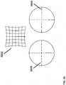
- FIG. 21 illustrates an appearance of a ring registration fixture on an x-ray when the x-ray collector is parallel with the planes of the rings and the rings are concentric with the x-ray collector.
- FIG. 22 illustrates a theoretical appearance of a ring registration fixture on an x-ray when the fixture is at a severe angle relative to the collector plate and the rings.
- FIG. 23 illustrates a transformation step for rotation by ⁇ about z in a coordinate system mapping process.
- FIG. 24 illustrates a transformation step for rotation about y by ⁇ in a coordinate system mapping process.
- FIG. 25 illustrates a transformation step for rotation in plane to match a radiograph's perspective in a coordinate system mapping process.
- FIG. 26 illustrates a transformation step for displacement from a coordinate system center by dx, dy in a coordinate system mapping process.
- FIG. 27 illustrates a transformation step of magnification according to parallax in a coordinate system mapping process.
- FIG. 28 illustrates a schematic of key dimensions looking at a plane perpendicular to a collector plate's plane with rings parallel to the collector in the field of view whose shadows appear on the collector plate.
- FIG. 29 illustrates a view across a ring that is at an arbitrary incidence angle to the collector plane from a perspective looking across the ring plane, where the ring plane is in and out of the page.
- FIG. 30 illustrates a view across a pair of concentric rings that are at an arbitrary incidence angle to the collector plane from a perspective looking across a ring plane, where the ring plane is in and out of the page.
- FIG. 31 illustrates a view of a ring at an arbitrary incidence angle from a rotated perspective.
- FIG. 32 illustrates a view of a pair of rings at an arbitrary incidence angle.
- FIG. 36 illustrates a pincushion distortion
- FIG. 37 illustrates an s-distortion
- FIGS. 1 and 2 illustrate a surgical robot system 100 in accordance with an exemplary embodiment.
- Surgical robot system 100 may include, for example, a surgical robot 102 , one or more robot arms 104 , a base 106 , a display 110 , an end-effector 112 , for example, including a guide tube 114 , and one or more tracking markers 118 .
- the surgical robot system 100 may include a patient tracking device 116 also including one or more tracking markers 118 , which is adapted to be secured directly to the patient 210 (e.g., to the bone of the patient 210 ).
- the surgical robot system 100 may also utilize a camera 200 , for example, positioned on a camera stand 202 .
- the camera stand 202 can have any suitable configuration to move, orient, and support the camera 200 in a desired position.
- the camera 200 may include any suitable camera or cameras, such as one or more infrared cameras (e.g., bifocal or stereophotogrammetric cameras), able to identify, for example, active and passive tracking markers 118 in a given measurement volume viewable from the perspective of the camera 200 .
- the camera 200 may scan the given measurement volume and detect the light that comes from the markers 118 in order to identify and determine the position of the markers 118 in three-dimensions.
- active markers 118 may include infrared-emitting markers that are activated by an electrical signal (e.g., infrared light emitting diodes (LEDs)), and passive markers 118 may include retro-reflective markers that reflect infrared light (e.g., they reflect incoming IR radiation into the direction of the incoming light), for example, emitted by illuminators on the camera 200 or other suitable device.
- LEDs infrared light emitting diodes
- FIGS. 1 and 2 illustrate a potential configuration for the placement of the surgical robot system 100 in an operating room environment.
- the robot 102 may be positioned near or next to patient 210 . Although depicted near the head of the patient 210 , it will be appreciated that the robot 102 can be positioned at any suitable location near the patient 210 depending on the area of the patient 210 undergoing the operation.
- the camera 200 may be separated from the robot system 100 and positioned at the foot of patient 210 . This location allows the camera 200 to have a direct visual line of sight to the surgical field 208 . Again, it is contemplated that the camera 200 may be located at any suitable position having line of sight to the surgical field 208 .
- the surgeon 120 may be positioned across from the robot 102 , but is still able to manipulate the end-effector 112 and the display 110 .
- a surgical assistant 126 may be positioned across from the surgeon 120 again with access to both the end-effector 112 and the display 110 . If desired, the locations of the surgeon 120 and the assistant 126 may be reversed. The traditional areas for the anesthesiologist 122 and the nurse or scrub tech 124 remain unimpeded by the locations of the robot 102 and camera 200 .
- the display 110 can be attached to the surgical robot 102 and in other exemplary embodiments, display 110 can be detached from surgical robot 102 , either within a surgical room with the surgical robot 102 , or in a remote location.
- End-effector 112 may be coupled to the robot arm 104 and controlled by at least one motor.
- end-effector 112 can comprise a guide tube 114 , which is able to receive and orient a surgical instrument 608 (described further herein) used to perform surgery on the patient 210 .
- end-effector is used interchangeably with the terms “end-effectuator” and “effectuator element.”
- end-effector 112 may be replaced with any suitable instrumentation suitable for use in surgery.
- end-effector 112 can comprise any known structure for effecting the movement of the surgical instrument 608 in a desired manner.
- the surgical robot 102 is able to control the translation and orientation of the end-effector 112 .
- the robot 102 is able to move end-effector 112 along x-, y-, and z-axes, for example.
- the end-effector 112 can be configured for selective rotation about one or more of the x-, y-, and z-axis, and a Z Frame axis (such that one or more of the Euler Angles (e.g., roll, pitch, and/or yaw) associated with end-effector 112 can be selectively controlled).
- selective control of the translation and orientation of end-effector 112 can permit performance of medical procedures with significantly improved accuracy compared to conventional robots that utilize, for example, a six degree of freedom robot arm comprising only rotational axes.
- the surgical robot system 100 may be used to operate on patient 210 , and robot arm 104 can be positioned above the body of patient 210 , with end-effector 112 selectively angled relative to the z-axis toward the body of patient 210 .
- the position of the surgical instrument 608 can be dynamically updated so that surgical robot 102 can be aware of the location of the surgical instrument 608 at all times during the procedure. Consequently, in some exemplary embodiments, surgical robot 102 can move the surgical instrument 608 to the desired position quickly without any further assistance from a physician (unless the physician so desires). In some further embodiments, surgical robot 102 can be configured to correct the path of the surgical instrument 608 if the surgical instrument 608 strays from the selected, preplanned trajectory. In some exemplary embodiments, surgical robot 102 can be configured to permit stoppage, modification, and/or manual control of the movement of end-effector 112 and/or the surgical instrument 608 .
- a physician or other user can operate the system 100 , and has the option to stop, modify, or manually control the autonomous movement of end-effector 112 and/or the surgical instrument 608 .
- Further details of surgical robot system 100 including the control and movement of a surgical instrument 608 by surgical robot 102 can be found in co-pending U.S. patent application Ser. No. 13/924,505, which is incorporated herein by reference in its entirety.
- the robotic surgical system 100 can comprise one or more tracking markers 118 configured to track the movement of robot arm 104 , end-effector 112 , patient 210 , and/or the surgical instrument 608 in three dimensions.
- a plurality of tracking markers 118 can be mounted (or otherwise secured) thereon to an outer surface of the robot 102 , such as, for example and without limitation, on base 106 of robot 102 , on robot arm 104 , or on the end-effector 112 .
- at least one tracking marker 118 of the plurality of tracking markers 118 can be mounted or otherwise secured to the end-effector 112 .
- One or more tracking markers 118 can further be mounted (or otherwise secured) to the patient 210 .
- the plurality of tracking markers 118 can be positioned on the patient 210 spaced apart from the surgical field 208 to reduce the likelihood of being obscured by the surgeon, surgical tools, or other parts of the robot 102 . Further, one or more tracking markers 118 can be further mounted (or otherwise secured) to the surgical tools 608 (e.g., a screw driver, dilator, implant inserter, or the like). Thus, the tracking markers 118 enable each of the marked objects (e.g., the end-effector 112 , the patient 210 , and the surgical tools 608 ) to be tracked by the robot 102 .
- the marked objects e.g., the end-effector 112 , the patient 210 , and the surgical tools 608
- system 100 can use tracking information collected from each of the marked objects to calculate the orientation and location, for example, of the end-effector 112 , the surgical instrument 608 (e.g., positioned in the tube 114 of the end-effector 112 ), and the relative position of the patient 210 .
- one or more of markers 118 may be optical markers.
- the positioning of one or more tracking markers 118 on end-effector 112 can maximize the accuracy of the positional measurements by serving to check or verify the position of end-effector 112 .
- Exemplary embodiments include one or more markers 118 coupled to the surgical instrument 608 .
- these markers 118 for example, coupled to the patient 210 and surgical instruments 608 , as well as markers 118 coupled to the end-effector 112 of the robot 102 can comprise conventional infrared light-emitting diodes (LEDs) or an Optotrak® diode capable of being tracked using a commercially available infrared optical tracking system such as Optotrak®.
- Optotrak® is a registered trademark of Northern Digital Inc., Waterloo, Ontario, Canada.
- markers 118 can comprise conventional reflective spheres capable of being tracked using a commercially available optical tracking system such as Polaris Spectra.
- the markers 118 coupled to the end-effector 112 are active markers which comprise infrared light-emitting diodes which may be turned on and off, and the markers 118 coupled to the patient 210 and the surgical instruments 608 comprise passive reflective spheres.
- markers 118 can comprise a radio-frequency and/or electromagnetic reflector or transceiver and the camera 200 can include or be replaced by a radio-frequency and/or electromagnetic transceiver.
- FIG. 3 illustrates a surgical robot system 300 and camera stand 302 , in a docked configuration, consistent with an exemplary embodiment of the present disclosure.
- Surgical robot system 300 may comprise a robot 301 including a display 304 , upper arm 306 , lower arm 308 , end-effector 310 , vertical column 312 , casters 314 , cabinet 316 , tablet drawer 318 , connector panel 320 , control panel 322 , and ring of information 324 .
- Camera stand 302 may comprise camera 326 . These components are described in greater with respect to FIG. 5 .
- FIG. 5 FIG.
- FIG. 3 illustrates the surgical robot system 300 in a docked configuration where the camera stand 302 is nested with the robot 301 , for example, when not in use. It will be appreciated by those skilled in the art that the camera 326 and robot 301 may be separated from one another and positioned at any appropriate location during the surgical procedure, for example, as shown in FIGS. 1 and 2 .
- FIG. 4 illustrates a base 400 consistent with an exemplary embodiment of the present disclosure. Base 400 may be a portion of surgical robot system 300 and comprise cabinet 316 .
- Cabinet 316 may house certain components of surgical robot system 300 including but not limited to a battery 402 , a power distribution module 404 , a platform interface board module 406 , a computer 408 , a handle 412 , and a tablet drawer 414 . The connections and relationship between these components is described in greater detail with respect to FIG. 5 .
- FIG. 5 illustrates a block diagram of certain components of an exemplary embodiment of surgical robot system 300 .
- Surgical robot system 300 may comprise platform subsystem 502 , computer subsystem 504 , motion control subsystem 506 , and tracking subsystem 532 .
- Platform subsystem 502 may further comprise battery 402 , power distribution module 404 , platform interface board module 406 , and tablet charging station 534 .
- Computer subsystem 504 may further comprise computer 408 , display 304 , and speaker 536 .
- Motion control subsystem 506 may further comprise driver circuit 508 , motors 510 , 512 , 514 , 516 , 518 , stabilizers 520 , 522 , 524 , 526 , end-effector 310 , and controller 538 .
- Tracking subsystem 532 may further comprise position sensor 540 and camera converter 542 .
- System 300 may also comprise a foot pedal 544 and tablet 546 .
- Input power is supplied to system 300 via a power source 548 which may be provided to power distribution module 404 .
- Power distribution module 404 receives input power and is configured to generate different power supply voltages that are provided to other modules, components, and subsystems of system 300 .
- Power distribution module 404 may be configured to provide different voltage supplies to platform interface module 406 , which may be provided to other components such as computer 408 , display 304 , speaker 536 , driver 508 to, for example, power motors 512 , 514 , 516 , 518 and end-effector 310 , motor 510 , ring 324 , camera converter 542 , and other components for system 300 for example, fans for cooling the electrical components within cabinet 316 .
- Power distribution module 404 may also provide power to other components such as tablet charging station 534 that may be located within tablet drawer 318 .
- Tablet charging station 534 may be in wireless or wired communication with tablet 546 for charging table 546 .
- Tablet 546 may be used by a surgeon consistent with the present disclosure and described herein.
- Power distribution module 404 may also be connected to battery 402 , which serves as temporary power source in the event that power distribution module 404 does not receive power from input power 548 . At other times, power distribution module 404 may serve to charge battery 402 if necessary.
- Connector panel 320 may serve to connect different devices and components to system 300 and/or associated components and modules.
- Connector panel 320 may contain one or more ports that receive lines or connections from different components.
- connector panel 320 may have a ground terminal port that may ground system 300 to other equipment, a port to connect foot pedal 544 to system 300 , a port to connect to tracking subsystem 532 , which may comprise position sensor 540 , camera converter 542 , and cameras 326 associated with camera stand 302 .
- Connector panel 320 may also include other ports to allow USB, Ethernet, HDMI communications to other components, such as computer 408 .
- Control panel 322 may provide various buttons or indicators that control operation of system 300 and/or provide information regarding system 300 .
- control panel 322 may include buttons to power on or off system 300 , lift or lower vertical column 312 , and lift or lower stabilizers 520 - 526 that may be designed to engage casters 314 to lock system 300 from physically moving.
- Other buttons may stop system 300 in the event of an emergency, which may remove all motor power and apply mechanical brakes to stop all motion from occurring.
- Control panel 322 may also have indicators notifying the user of certain system conditions such as a line power indicator or status of charge for battery 402 .
- Ring 324 may be a visual indicator to notify the user of system 300 of different modes that system 300 is operating under and certain warnings to the user.
- Computer subsystem 504 includes computer 408 , display 304 , and speaker 536 .
- Computer 504 includes an operating system and software to operate system 300 .
- Computer 504 may receive and process information from other components (for example, tracking subsystem 532 , platform subsystem 502 , and/or motion control subsystem 506 ) in order to display information to the user. Further, computer subsystem 504 may also include speaker 536 to provide audio to the user.
- Tracking subsystem 532 may include position sensor 504 and converter 542 . Tracking subsystem 532 may correspond to camera stand 302 including camera 326 as described with respect to FIG. 3 . Position sensor 504 may be camera 326 . Tracking subsystem may track the location of certain markers that are located on the different components of system 300 and/or instruments used by a user during a surgical procedure. This tracking may be conducted in a manner consistent with the present disclosure including the use of infrared technology that tracks the location of active or passive elements, such as LEDs or reflective markers, respectively. The location, orientation, and position of structures having these types of markers may be provided to computer 408 which may be shown to a user on display 304 .
- a surgical instrument 608 having these types of markers and tracked in this manner may be shown to a user in relation to a three dimensional image of a patient's anatomical structure.
- Motion control subsystem 506 may be configured to physically move vertical column 312 , upper arm 306 , lower arm 308 , or rotate end-effector 310 .
- the physical movement may be conducted through the use of one or more motors 510 - 518 .
- motor 510 may be configured to vertically lift or lower vertical column 312 .
- Motor 512 may be configured to laterally move upper arm 308 around a point of engagement with vertical column 312 as shown in FIG. 3 .
- Motor 514 may be configured to laterally move lower arm 308 around a point of engagement with upper arm 308 as shown in FIG. 3 .
- Motors 516 and 518 may be configured to move end-effector 310 in a manner such that one may control the roll and one may control the tilt, thereby providing multiple angles that end-effector 310 may be moved. These movements may be achieved by controller 538 which may control these movements through load cells disposed on end-effector 310 and activated by a user engaging these load cells to move system 300 in a desired manner.
- system 300 may provide for automatic movement of vertical column 312 , upper arm 306 , and lower arm 308 through a user indicating on display 304 (which may be a touchscreen input device) the location of a surgical instrument or component on three dimensional image of the patient's anatomy on display 304 .
- the user may initiate this automatic movement by stepping on foot pedal 544 or some other input means.
- FIG. 6 illustrates a surgical robot system 600 consistent with an exemplary embodiment.
- Surgical robot system 600 may comprise end-effector 602 , robot arm 604 , guide tube 606 , instrument 608 , and robot base 610 .
- Instrument tool 608 may be attached to a tracking array 612 including one or more tracking markers (such as markers 118 ) and have an associated trajectory 614 .
- Trajectory 614 may represent a path of movement that instrument tool 608 is configured to travel once it is positioned through or secured in guide tube 606 , for example, a path of insertion of instrument tool 608 into a patient.
- robot base 610 may be configured to be in electronic communication with robot arm 604 and end-effector 602 so that surgical robot system 600 may assist a user (for example, a surgeon) in operating on the patient 210 .
- Surgical robot system 600 may be consistent with previously described surgical robot system 100 and 300 .
- a tracking array 612 may be mounted on instrument 608 to monitor the location and orientation of instrument tool 608 .
- the tracking array 612 may be attached to an instrument 608 and may comprise tracking markers 804 .
- tracking markers 804 may be, for example, light emitting diodes and/or other types of reflective markers (e.g., markers 118 as described elsewhere herein).
- the tracking devices may be one or more line of sight devices associated with the surgical robot system.
- the tracking devices may be one or more cameras 200 , 326 associated with the surgical robot system 100 , 300 and may also track tracking array 612 for a defined domain or relative orientations of the instrument 608 in relation to the robot arm 604 , the robot base 610 , end-effector 602 , and/or the patient 210 .
- the tracking devices may be consistent with those structures described in connection with camera stand 302 and tracking subsystem 532 .
- FIGS. 7A, 7B, and 7C illustrate a top view, front view, and side view, respectively, of end-effector 602 consistent with an exemplary embodiment.
- End-effector 602 may comprise one or more tracking markers 702 .
- Tracking markers 702 may be light emitting diodes or other types of active and passive markers, such as tracking markers 118 that have been previously described.
- the tracking markers 702 are active infrared-emitting markers that are activated by an electrical signal (e.g., infrared light emitting diodes (LEDs)).
- LEDs infrared light emitting diodes
- tracking markers 702 may be activated such that the infrared markers 702 are visible to the camera 200 , 326 or may be deactivated such that the infrared markers 702 are not visible to the camera 200 , 326 .
- the end-effector 602 may be controlled by the system 100 , 300 , 600 , and when the markers 702 are deactivated, the end-effector 602 may be locked in position and unable to be moved by the system 100 , 300 , 600 .
- Markers 702 may be disposed on or within end-effector 602 in a manner such that the markers 702 are visible by one or more cameras 200 , 326 or other tracking devices associated with the surgical robot system 100 , 300 , 600 .
- the camera 200 , 326 or other tracking devices may track end-effector 602 as it moves to different positions and viewing angles by following the movement of tracking markers 702 .
- the location of markers 702 and/or end-effector 602 may be shown on a display 110 , 304 associated with the surgical robot system 100 , 300 , 600 , for example, display 110 as shown in FIG. 2 and/or display 304 shown in FIG. 3 .
- This display 110 , 304 may allow a user to ensure that end-effector 602 is in a desirable position in relation to robot arm 604 , robot base 610 , the patient 210 , and/or the user.
- markers 702 may be placed around the surface of end-effector 602 so that a tracking device placed away from the surgical field 208 and facing toward the robot 102 , 301 and the camera 200 , 326 is able to view at least 3 of the markers 702 through a range of common orientations of the end-effector 602 relative to the tracking device 100 , 300 , 600 .
- distribution of markers 702 in this way allows end-effector 602 to be monitored by the tracking devices when end-effector 602 is translated and rotated in the surgical field 208 .
- end-effector 602 may be equipped with infrared (IR) receivers that can detect when an external camera 200 , 326 is getting ready to read markers 702 . Upon this detection, end-effector 602 may then illuminate markers 702 . The detection by the IR receivers that the external camera 200 , 326 is ready to read markers 702 may signal the need to synchronize a duty cycle of markers 702 , which may be light emitting diodes, to an external camera 200 , 326 . This may also allow for lower power consumption by the robotic system as a whole, whereby markers 702 would only be illuminated at the appropriate time instead of being illuminated continuously. Further, in exemplary embodiments, markers 702 may be powered off to prevent interference with other navigation tools, such as different types of surgical instruments 608 .
- IR infrared
- FIG. 8 depicts one type of surgical instrument 608 including a tracking array 612 and tracking markers 804 .
- Tracking markers 804 may be of any type described herein including but not limited to light emitting diodes or reflective spheres. Markers 804 are monitored by tracking devices associated with the surgical robot system 100 , 300 , 600 and may be one or more of the line of sight cameras 200 , 326 . The cameras 200 , 326 may track the location of instrument 608 based on the position and orientation of tracking array 612 and markers 804 .
- a user such as a surgeon 120 may orient instrument 608 in a manner so that tracking array 612 and markers 804 are sufficiently recognized by the tracking device or camera 200 , 326 to display instrument 608 and markers 804 on, for example, display 110 of the exemplary surgical robot system.
- the manner in which a surgeon 120 may place instrument 608 into guide tube 606 of the end-effector 602 and adjust the instrument 608 is evident in FIG. 8 .
- the hollow tube or guide tube 114 , 606 of the end-effector 112 , 310 , 602 is sized and configured to receive at least a portion of the surgical instrument 608 .
- the guide tube 114 , 606 is configured to be oriented by the robot arm 104 such that insertion and trajectory for the surgical instrument 608 is able to reach a desired anatomical target within or upon the body of the patient 210 .
- the surgical instrument 608 may include at least a portion of a generally cylindrical instrument.
- the surgical instrument 608 may include one or more of a guide wire, cannula, a retractor, a drill, a reamer, a screw driver, an insertion tool, a removal tool, or the like.
- the hollow tube 114 , 606 is generally shown as having a cylindrical configuration, it will be appreciated by those of skill in the art that the guide tube 114 , 606 may have any suitable shape, size and configuration desired to accommodate the surgical instrument 608 and access the surgical site.
- FIGS. 9A-9C illustrate end-effector 602 and a portion of robot arm 604 consistent with an exemplary embodiment.
- End-effector 602 may further comprise body 1202 and clamp 1204 .
- Clamp 1204 may comprise handle 1206 , balls 1208 , spring 1210 , and lip 1212 .
- Robot arm 604 may further comprise depressions 1214 , mounting plate 1216 , lip 1218 , and magnets 1220 .
- End-effector 602 may mechanically interface and/or engage with the surgical robot system and robot arm 604 through one or more couplings.
- end-effector 602 may engage with robot arm 604 through a locating coupling and/or a reinforcing coupling.
- end-effector 602 may fasten with robot arm 604 outside a flexible and sterile barrier.
- the locating coupling may be a magnetically kinematic mount and the reinforcing coupling may be a five bar over center clamping linkage.
- robot arm 604 may comprise mounting plate 1216 , which may be non-magnetic material, one or more depressions 1214 , lip 1218 , and magnets 1220 .
- Magnet 1220 is mounted below each of depressions 1214 .
- Portions of clamp 1204 may comprise magnetic material and be attracted by one or more magnets 1220 .
- balls 1208 become seated into respective depressions 1214 .
- balls 1208 as shown in FIG. 9B would be seated in depressions 1214 as shown in FIG. 9A .
- This seating may be considered a magnetically-assisted kinematic coupling.
- Magnets 1220 may be configured to be strong enough to support the entire weight of end-effector 602 regardless of the orientation of end-effector 602 .
- the locating coupling may be any style of kinematic mount that uniquely restrains six degrees of freedom.
- portions of clamp 1204 may be configured to be a fixed ground link and as such clamp 1204 may serve as a five bar linkage.
- Closing clamp handle 1206 may fasten end-effector 602 to robot arm 604 as lip 1212 and lip 1218 engage clamp 1204 in a manner to secure end-effector 602 and robot arm 604 .
- spring 1210 may be stretched or stressed while clamp 1204 is in a locked position.
- the locked position may be a position that provides for linkage past center. Because of a closed position that is past center, the linkage will not open absent a force applied to clamp handle 1206 to release clamp 1204 .
- end-effector 602 may be robustly secured to robot arm 604 .
- Spring 1210 may be a curved beam in tension.
- Spring 1210 may be comprised of a material that exhibits high stiffness and high yield strain such as virgin PEEK (poly-ether-ether-ketone).
- the linkage between end-effector 602 and robot arm 604 may provide for a sterile barrier between end-effector 602 and robot arm 604 without impeding fastening of the two couplings.
- the reinforcing coupling may be a linkage with multiple spring members.
- the reinforcing coupling may latch with a cam or friction based mechanism.
- the reinforcing coupling may also be a sufficiently powerful electromagnet that will support fastening end-effector 102 to robot arm 604 .
- the reinforcing coupling may be a multi-piece collar completely separate from either end-effector 602 and/or robot arm 604 that slips over an interface between end-effector 602 and robot arm 604 and tightens with a screw mechanism, an over center linkage, or a cam mechanism.
- a registration system 1400 may be used as illustrated in FIG. 10 .
- a patient tracking device 116 may include a patient fixation instrument 1402 to be secured to a rigid anatomical structure of the patient 210 and a dynamic reference base (DRB) 1404 may be securely attached to the patient fixation instrument 1402 .
- patient fixation instrument 1402 may be inserted into opening 1406 of dynamic reference base 1404 .
- Dynamic reference base 1404 may contain markers 1408 that are visible to tracking devices, such as tracking subsystem 532 . These markers 1408 may be optical markers or reflective spheres, such as tracking markers 118 , as previously discussed herein.
- Patient fixation instrument 1402 is attached to a rigid anatomy of the patient 210 and may remain attached throughout the surgical procedure.
- patient fixation instrument 1402 is attached to a rigid area of the patient 210 , for example, a bone that is located away from the targeted anatomical structure subject to the surgical procedure.
- dynamic reference base 1404 is associated with the targeted anatomical structure through the use of a registration fixture that is temporarily placed on or near the targeted anatomical structure in order to register the dynamic reference base 1404 with the location of the targeted anatomical structure.
- a registration fixture 1410 is attached to patient fixation instrument 1402 through the use of a pivot arm 1412 .
- Pivot arm 1412 is attached to patient fixation instrument 1402 by inserting patient fixation instrument 1402 through an opening 1414 of registration fixture 1410 .
- Pivot arm 1412 is attached to registration fixture 1410 by, for example, inserting a knob 1416 through an opening 1418 of pivot arm 1412 .
- registration fixture 1410 may be placed over the targeted anatomical structure and its location may be determined in an image space and navigation space using tracking markers 1420 and/or fiducials 1422 on registration fixture 1410 .
- Registration fixture 1410 may contain a collection of markers 1420 that are visible in a navigational space (for example, markers 1420 may be detectable by tracking subsystem 532 ).
- Tracking markers 1420 may be optical markers visible in infrared light as previously described herein.
- Registration fixture 1410 may also contain a collection of fiducials 1422 , for example, such as bearing balls, that are visible in an imaging space (for example, a three dimension CT image). As described in greater detail with respect to FIG.
- the targeted anatomical structure may be associated with dynamic reference base 1404 thereby allowing depictions of objects in the navigational space to be overlaid on images of the anatomical structure.
- Dynamic reference base 1404 located at a position away from the targeted anatomical structure, may become a reference point thereby allowing removal of registration fixture 1410 and/or pivot arm 1412 from the surgical area.
- FIG. 11 provides an exemplary method 1500 for registration consistent with the present disclosure.
- Method 1500 begins at step 1502 wherein a graphical representation (or image(s)) of the targeted anatomical structure may be imported into system 100 , 300 600 , for example computer 408 .
- the graphical representation may be three dimensional CT or a fluoroscope scan of the targeted anatomical structure of the patient 210 which includes registration fixture 1410 and a detectable imaging pattern of fiducials 1420 .
- an imaging pattern of fiducials 1420 is detected and registered in the imaging space and stored in computer 408 .
- a graphical representation of the registration fixture 1410 may be overlaid on the images of the targeted anatomical structure.
- a navigational pattern of registration fixture 1410 is detected and registered by recognizing markers 1420 .
- Markers 1420 may be optical markers that are recognized in the navigation space through infrared light by tracking subsystem 532 via position sensor 540 .
- registration fixture 1410 may be recognized in both the image space through the use of fiducials 1422 and the navigation space through the use of markers 1420 .
- the registration of registration fixture 1410 in the image space is transferred to the navigation space. This transferal is done, for example, by using the relative position of the imaging pattern of fiducials 1422 compared to the position of the navigation pattern of markers 1420 .
- registration of the navigation space of registration fixture 1410 (having been registered with the image space) is further transferred to the navigation space of dynamic registration array 1404 attached to patient fixture instrument 1402 .
- registration fixture 1410 may be removed and dynamic reference base 1404 may be used to track the targeted anatomical structure in both the navigation and image space because the navigation space is associated with the image space.
- the navigation space may be overlaid on the image space and objects with markers visible in the navigation space (for example, surgical instruments 608 with optical markers 804 ).
- the objects may be tracked through graphical representations of the surgical instrument 608 on the images of the targeted anatomical structure.
- FIGS. 12A-12B illustrate imaging devices 1304 that may be used in conjunction with robot systems 100 , 300 , 600 to acquire pre-operative, intra-operative, post-operative, and/or real-time image data of patient 210 .
- Any appropriate subject matter may be imaged for any appropriate procedure using the imaging system 1304 .
- the imaging system 1304 may be any imaging device such as imaging device 1306 and/or a C-arm 1308 device. It may be desirable to take x-rays of patient 210 from a number of different positions, without the need for frequent manual repositioning of patient 210 which may be required in an x-ray system. As illustrated in FIG.
- the imaging system 1304 may be in the form of a C-arm 1308 that includes an elongated C-shaped member terminating in opposing distal ends 1312 of the “C” shape.
- C-shaped member 1130 may further comprise an x-ray source 1314 and an image receptor 1316 .
- the space within C-arm 1308 of the arm may provide room for the physician to attend to the patient substantially free of interference from x-ray support structure 1318 .
- the imaging system may include imaging device 1306 having a gantry housing 1324 attached to a support structure imaging device support structure 1328 , such as a wheeled mobile cart 1330 with wheels 1332 , which may enclose an image capturing portion, not illustrated.
- the image capturing portion may include an x-ray source and/or emission portion and an x-ray receiving and/or image receiving portion, which may be disposed about one hundred and eighty degrees from each other and mounted on a rotor (not illustrated) relative to a track of the image capturing portion.
- the image capturing portion may be operable to rotate three hundred and sixty degrees during image acquisition.
- the image capturing portion may rotate around a central point and/or axis, allowing image data of patient 210 to be acquired from multiple directions or in multiple planes.
- a calibrating fixture may be attached to the image intensifier of a fluoroscope, such as illustrated in FIG. 13 .
- the fixture contains rows of small metallic spheres (hereafter referred to as ‘BBs’) with known spacing that appear on the x-ray image, and also contains an optical tracking array that provides the three-dimensional (3D) position of the fixture in the tracking space.
- BBs small metallic spheres
- 3D three-dimensional
- the 3D position of the tool which has a tracking array attached, is tracked in the coordinate system of the tracker (e.g., cameras). Then, a graphical representation of the tool is overlaid on the x-ray images to provide “virtual fluoroscopy” with roughly the same visual information that would be seen if continuous x-rays were taken while holding the tool in the surgical field.
- a benefit of this method is that the patient and medical staff are exposed to much less radiation as the virtual fluoroscopy can provide continuous updates of tool position overlaid on a single x-ray image.
- FIG. 14 illustrates an x-ray (e.g., fluoroscope) collector plate 1702 showing the theoretical projection of BBs 1710 within two planes 1704 and 1706 at different distances from the source 1708 .
- X-ray collector plate 1702 , Plane 1 1706 , and Plane 2 1704 are shown as being parallel and concentric.
- the x-ray emitter 1708 is assumed to be a point, and rays from the source to collector travel out from this point in a conical pattern. Because of this conical pattern, the BBs 1710 from Plane 1 1706 appear magnified on the x-ray collector plate 1702 relative to the BBs 1710 from Plane 2 1704 , although they are actually spaced the same in this example. This phenomenon is known as parallax.
- vectors could mean vectors determined from visible x-ray shadows of the BBs, or any vector calculated (e.g., interpolated) to match the conical pattern deduced from the visible x-ray shadows.
- the 3D position of that anatomical point of interest may then be determined because there is a unique solution at the intersection of the vectors from the two views. That is, from one view, it is not possible to deduce 3D position of a reference point because the point could be anywhere along the vector from source to emitter and would appear at the same location on the collector plate.
- the second view provides the unique position along the vector where the point must be.
- FIG. 14 shows just 4 BBs 1710 on two parallel planes 1704 and 1706 .
- These BBs could provide the basis for methods to detect the position of an object in 3D from multiple 2D x-ray views.
- a dense grid of BBs such as shown in FIG. 16 (e.g., tens or hundreds) could be used instead, which would allow vectors to be more accurately interpolated.
- the use of more BBs allows more accurate interpolation and ultimately better 3D accuracy, but x-ray shadows from more BBs also obstructs the surgeon from being able to visualize the anatomy of interest on the x-ray image.
- Implicit assumptions are that the positions of the collector plate and emitter source are known in 3D during both shots.
- the collector plate may have a tracking array attached and its 3D position would therefore be directly tracked. It may also be possible to place a tracker on the emitter.
- the tracking field needs to be very large to observe both trackers, where the distance between collector and emitter may typically be on the order of one meter. Tracking systems such as optical trackers may only have a tracking field less than one cubic meter.
- the emitter could be positioned out of view for some clinically typical x-ray shots.
- the emitter source location could instead be calibrated relative to the collector array, but the extrapolated accuracy in defining the emitter location may be low with a large distance between collector and emitter and the different amounts of sag when the fluoroscope is oriented differently.
- the emitter source distance and direction relative to the collector may be calculated from fluoroscopic images of two parallel planes of BBs with known spacing d ab 1712 , such as is shown in FIG. 14 and FIG. 17 .
- the equations provided in Equation 1 hold based on the geometry 2000 depicted in FIG. 17 .
- FIG. 17 indicates that the distances between shadows of two adjacent BBs in two planes are measured. In practice, the distances between several pairs of BBs on the x-ray image may be measured and these distances averaged. Additionally, FIG. 17 shows the distances between BBs on Plane A and Plane B as being the same, however, their physical distances may differ and is accounted for by l a and l b in the equations. In practice, it may be desirable to make the BBs offset rather than spaced the same and aligned to prevent their projections from partially obscuring each other.
- This method for defining the position of the emitter relative to the collector makes use of the two parallel plates in defining the direction of the emitter as well as the distance.
- the direction from emitter to collector is assumed to be perpendicular to the plane of the collector and the planes containing BBs. If this assumption is untrue, the projections of BBs from the near and far field planes will not be symmetrically overlaid on x-ray images.
- the amount of offset of BB shadows from a symmetrical projection is proportional to the distance between BB planes, with larger plane separation manifesting as larger lateral displacements of the projections on the x-ray images.
- the lateral offsets of BB shadows can be used to determine accurately the actual orientation of the BB planes relative to the collector plane and therefore the position of the emitter in 3D, or used to manually or automatically adjust the orientation of the registration fixture on the image intensifier until BB planes and collector plate are truly coplanar.
- Equation 3 To map a 3D point with coordinates x,y,z onto a 2D x-ray image that has the X and Y axes of the image aligned with the x and y axes of the Cartesian coordinate system, Equation 3 holds.
- X is the coordinate axis of the 2D x-ray image aligned with the Cartesian X-axis
- Y is the coordinate axis of the 2D x-ray image aligned with the Cartesian y-axis
- z is the Cartesian axis perpendicular to the x-ray image.
- (X1, Y1) could be defined as the x-ray coordinates of a point (x, y, z) as the point appears on an x-ray image 1 (e.g., an anteroposterior image).
- the Cartesian coordinates of the point in a local coordinate system aligned with that x-ray plane could be defined as (x1, y1, z1).
- (X2, Y2) could be defined as the x-ray coordinates of the same point as it appears on an x-ray image 2 (e.g., a lateral image).
- the Cartesian coordinates of the point in a local coordinate system aligned with that x-ray plane could be defined as (x2, y2, z2). Because a tracking system may be used to detect the 3D position of the x-ray collector while the fluoroscope is in each orientation, the transformation T 12 from Cartesian coordinate system 1 to Cartesian coordinate system 2 is known, with T 12 being a standard 4 ⁇ 4 transformation matrix as is commonly used in the field. There is therefore a unique solution that results in Equation 4.
- the two coordinate systems are each oriented with their z-axis perpendicular to each x-ray plane, the origin of their z-axis at each x-ray plane, and the origins of their x and y axes at the center of the x-ray plane.
- the direction of x and y relative to the x-ray planes may be arbitrary.
- a method for defining the 3D Cartesian coordinate system associated with two fluoroscopic views may assume that the BBs are projected uniformly onto the image intensifier.
- distortion is commonly associated with images obtained from fluoroscopes, such as pincushion distortion, s-distortion, and the like. These types of distortion may be corrected using image processing before applying the methods described herein. Distortion correction may make use of the fact that the BBs are arranged in a symmetrical pattern on the registration device. Therefore, the x-rays projected through the known symmetrical pattern should create an image with matching symmetry. Spacing between BBs and alignment of rows of BBs may be determined through image processing and compared to the expected projections of the BBs.
- Algorithms commonly known in image processing such as affine transformations and the like may be used to force the projected x-ray image to match the known and expected symmetry. Since the same correction may also be applied to anatomical images on the x-rays, the resulting x-ray images should represent undistorted projections and should allow valid calculation of registration as described herein.
- the symmetrical pattern used for correcting distortion could be a square pattern as depicted in FIG. 16 , a radially symmetrical pattern in which BBs are distributed in a polar coordinate system about the center of the image, where BBs share common radii and azimuth angles, or any suitable pattern as depicted in the fixture in FIGS. 18 and 19 .
- the corresponding shadows of the BBs on x-ray images can be predicted and distortion correction applied to force the image to match the expected pattern.
- the process of 2D to 3D mapping of images relies on the correct interpretation of direction on the x-ray image. For example, if a 2D x-ray image is an anteroposterior image, it must be known if the 2D image represents a shot with emitter anterior and collector posterior or a shot with emitter posterior and collector anterior. Additionally, since fluoroscopic images are commonly round, there must be a way to precisely determine from the BB shadows which direction points left, right, up or down.
- the fixture's plane of BB's may provide information for alignment correction, such as using BB's located closest to the x-ray collector to provide information to orient the x-ray image rotationally and also with regard to reflection, e.g., the BB pattern may determine whether the positive z direction extends off the front or back of the visible plane.
- the fixture may contain an outer ring of large BBs that are arranged so it uniquely identifies aspects of alignment, such as the rotation and flip of the image.
- the pattern of BBs for identifying orientation and/or flip may be chosen based on the ability of the pattern to provide a unique combination of image rotation and flip and on the ability of pattern to provide redundant BBs for increased reliability of detection. Redundant BBs may be important because it is possible that not all BBs would be visible on any given x-ray shot due to obstruction of the BB shadow from tools or implants, or poor x-ray penetration through parts of the image.
- a ring of BBs of varying spacing around the perimeter of a standard circular fluoroscopic image may be employed, such as illustrated in FIG. 19 where the shadows of the perimeter BBs form a bit code (e.g., 32 bit code).
- a first plane 2202 with a first array of points and a second plane 2204 with a second array of points may be projected to form a combined image 2206 .
- Code lengths should be selected to enable the spacing of the BBs to be far enough apart so there is a small chance that an error in detecting a BB's location could result in it falsely falling into an adjacent bit location while still providing enough information to be robust to missing bits.
- comparison of the subset against a known template may provide the correct image orientation and flip regardless of which BBs are missing. If a subset with a greater number of BBs missing is detected, an algorithm may determine the correct image orientation and flip. In embodiments, knowing the limitations of the algorithm, the system may require that a certain minimum number of BBs is detected before allowing the algorithm to proceed.
- orientation matching may utilize a point match algorithm (e.g., the Kabsch point match algorithm) or other suitable point match algorithm that assumes both point sets are scaled the same.
- the algorithm may then determine the transformation between two point sets, where one point set comes from the orientation BB detection and the other point set comes from a fixture 3D model.
- the fixture's orientation markers may then be projected into image space. Since both point sets need to be scaled the same, the algorithm tests a range of projection scaling to find the best match. Once the best match is found the transform is scaled appropriately, and the algorithm assigns point correspondence between the detected image markers and the physical fixture markers. The resulting transform can then be applied to the image to rotate and/or flip it to produce alignment with the fixture.
- rings or other shapes such as formed from radio-opaque materials such as metal wire, as fiducials in a registration fixture.
- a ring registration fixture 2300 is illustrated with two parallel rings 2304 and 2306 of the same or different diameters (e.g., between 50-300 mm), are positioned concentrically in parallel planes spaced apart (e.g., spaced apart by 50-300 mm).
- the rings may also have one or more crosshairs 2308 A and 2308 B formed of wire or other radio-opaque material of the same or different diameter as the rings themselves.
- rings that are exactly circular, that their crosshairs pass through the exact center so that diameters of the projected ellipses and crosshair intersection points are accurate, and the like. Additionally, it may be desirable that the cross-section of a ring be circular instead of flattened, so that if the ring is at an angle relative to the x-ray image it is properly projected. Possible methods for fashioning rings include welding or otherwise adhering segments of wire, rapid prototyping (3D printing) using a radiopaque building material, etching in the same manner as is used for fabrication of printed circuit boards, and the like.
- tracking markers 2302 A-D may be used as references for ring positioning of the ring registration fixture 2300 in 3D, such as utilizing an array of optical markers, a magnetic sensor, or other like 3D tracking method.
- a local coordinate system may have its origin at the center of the ring that is closer to the x-ray emitter, with the second (e.g., parallel) ring closer to the collector, and the x-axis and y-axis may be coincident with the crosshairs that identify the first ring's center, where the z-axis is coincident with the vector joining the centers of the two rings.
- mapping points from 3D to 2D using a ring registration fixture may utilize vectors through known points on both rings that are created to form a conical pattern, where this pattern is then used to interpolate vectors through regions of interest.
- a sequence of common transformations may be applied (i.e., rotations, translations, magnification), such as with the transformation parameters estimated from features on the images.
- a sequence of common transformations may be applied (i.e., rotations, translations, magnification), such as with the transformation parameters estimated from features on the images.
- near and far field rings may be the same diameter, where in order to map a point from this coordinate system to the coordinate system of the collector plate, a number of transformations may be applied.
- FIGS. 23-27 A non-limiting example set of illustrative transformations are depicted in FIGS. 23-27 .
- FIG. 23 depicts a transformation step 1 rotating by ⁇ about z (e.g., ⁇ is the angle allowing subsequent rotation a to occur about y). Note that in this figure, the rings are viewed in 3D without parallax, and so the near and far field rings exactly overlap in the starting orientation.
- FIG. 24 depicts a transformation step 2 rotating about y by ⁇ . Note that rotation occurs about the center of the near field ring (e.g., the ring closer to the emitter).
- FIG. 23 depicts a transformation step 1 rotating by ⁇ about z (e.g., ⁇ is the angle allowing subsequent rotation a to occur about y). Note that in this figure, the rings are viewed in 3D without parallax, and so the near and far field rings exactly overlap in the starting orientation.
- FIG. 24 depicts a transformation step 2 rotating about y by ⁇
- FIG. 25 depicts a transformation step 3 rotating in plane to match the radiograph's perspective (e.g., finding the angle in the x-y plane off of y to get to the actual axis of rotation instead of using y axis as the axis of rotation for incidence angle ⁇ ).
- FIG. 26 depicts a transformation step 4 displacing from coordinate system center by dx, dy.
- FIG. 27 depicts a transformation step 5 magnifying according to parallax. In this example, with step 5 complete, the x-y plane represents the points mapped to the 2D plane. In step 5 magnification occurs according to Equation 3.
- the ratio of d ec /k is needed, as was described respect to the BB fixture. This ratio may be determined similarly from an x-ray image taken of the rings while oriented parallel to the collector plate.
- FIG. 28 illustrates a schematic of key dimensions looking at a plane perpendicular to the collector plate's plane, and with rings parallel to the collector in the field of view whose shadows appear on the collector plate. Based on FIG. 28 , the following equations can be written to determine d ec /k:
- Non-limiting examples of how the five unknowns ( ⁇ , ⁇ , ⁇ , dx, and dy) may be determined will now be described.
- FIG. 30 illustrates a view across a pair of concentric rings that are at an arbitrary incidence angle to the collector plane from a perspective looking across the ring plane, where the ring plane is in and out of the page (see inset). Based on FIG. 30 , the following equation holds:
- Equation 11 dictates that the widest and narrowest projections of the rings be measured, and slight variations may lead to discrepancies in ⁇ . It is useful to seek an equation based on displacement of the ring centers instead, which is less sensitive to error. If the lower ring is “magnified” to match the known ratio of diameters of upper and lower rings (e.g., ratio of 1 if the rings are the same diameter), it would be the same as if the ring were moved up in the vertical direction (z direction) since scaling is done for values of each point on the ring in the coordinate system where ring points are offset from zero.
- This z position becomes the z position of the major axis of both ellipses.
- Image processing enables the scaling of the image of the far field ellipse about the center of the image until the far field ellipse diameter relative to the near field ellipse diameter match the expected ratio. For example, if the far field ring and near field ring physically have identical diameters, the x-ray projected far field ellipse will appear smaller than the near field ellipse. Points on the far field ellipse may then be scaled so that a new image of the far field ellipse would have the same diameter as the near field ellipse.
- the only point that needs to be scaled may be the center of the far field ellipse, as defined by the intersection of the far field ring's crosshairs.
- the offset in the centers of the ellipses represents the measurement in image coordinates of the side opposite in a triangle with hypotenuse equal to the distance between rings.
- the hypotenuse may be determined in image coordinates, where it is the distance between rings times the ratio of near field ellipse major axis over the near field ring diameter (or times the ratio of the scaled far field ellipse major axis over the far field ring diameter, which is by definition of the scaling factor the same).
- ⁇ can be found with an arcsine function.
- the azimuth angle ⁇ (the angle required to put the axis of rotation for ring incidence on the y-axis) is just the angle relative to the major axis of one of the ellipses.
- the long axis of both ellipses appears to be angled visibly relative to the y-axis; additionally, the long axis of the larger ellipse appears to have a different azimuth angle than that of the smaller ellipse.
- magnification is equivalent to moving the entire ring up the z-axis. Therefore, if the far field ring is scaled appropriately, the two elliptical ring images will represent a projection at the same z coordinate of the near and far field rings. If the center of the near and far field rings are at the same z coordinate, then the vector connecting them in x and y represents the path of the axis of rotation. The actual axis of rotation should be perpendicular to this path and also in the x-y plane. Therefore, the axis of rotation may be extracted through image processing by first scaling the far field ring center then tracing the path connecting the centers of the far field and near field ring images.
- the far field ellipse has been scaled about the center of the image until the near and far field ellipses are equal in their long axis.
- the angle ⁇ is the angle of the near field vertical crosshair relative to Y or horizontal crosshair relative to X after accounting for the perspective.
- crosshair is aligned with X or Y and which direction of a crosshair points to +X or +Y.
- This information can be determined from additional features on the fixture that appear on x-ray images, such as a BB or wire near the reference crosshair's positive axis or any other suitable feature.
- the offset position dx, dy is the offset of the x,y coordinate of the center of the near field ring.
- This point can be directly tracked based on the tracker on the fixture and the corresponding point seen on the resulting x-ray. This point can serve as a registration check. That is, if a navigated probe is pointed at the center of the near field ring, an image of a probe with its tip at the projected ellipse's crosshair intersection should be seen.
- the registration fixture is attached very precisely to the image intensifier, then several of the parameters referenced above go to zero. That is, the incidence angle ⁇ , axis of rotation reference ⁇ , displacements dx and dy all go to zero, simplifying the registration process.
- the locations of intersections of crosshairs and rings on x-rays could be used as adjustment tools instead of for extracting transformation parameters. That is, if an x-ray shows disparity in the intersections of the ring centers and edges, such as depicted in FIG. 21 , the fixture could be adjusted manually or automatically on the image intensifier until the x-rays show centering, at which point the transformations would be simplified and mapping would be at its best accuracy.
- FIGS. 36 and 37 show manifestations of pincushion and s-distortion on images when using ring fixtures.
- pincushion distortion is radially symmetrical about the center of the image, it is only necessary to see one crosshair and the markings to account for the pincushion distortion and correct it, assuming the crosshair runs through the image center from one edge to the other. If pincushion distortion is not symmetrical at different angles, then additional crosshairs may be needed to assess the magnitude of pincushion in different directions.
- FIG. 36 illustrates a pincushion distortion that might occur with a fluoroscope that would cause an x-ray that is shot through a square wire grid to appear as a pincushion distorted image 3602 .
- the pincushion pattern is shown more exaggerated than would be typical.
- a ring with crosshairs and evenly spaced gaps in the crosshairs is shown undistorted 3604 (left) and then with pincushion distortion 3606 (right). Note that the distortion has no effect on the ring but shows clearly on the spacing of the gaps in the crosshairs, with increasing spacing visible from the center outward to the ring.
- the magnitude of pincushion distortion is measured as the amount of increase in spacing between indices going from the center to the edge of the image. Similarly, barrel distortion would manifest as decreasing gaps in the crosshairs from image center to ring.
- FIG. 37 illustrates an s-distortion that might occur with a fluoroscope that would cause an x-ray that is shot through a square wire grid to appear as is shown as an s-distorted image 3702 .
- the s-pattern is shown more exaggerated than would be typical.
- a ring with crosshairs is shown undistorted 3704 (left) and then with s-distortion 3706 (right). Note that the distortion has no effect on the ring but shows clearly on the crosshairs, which have taken on the s-shape. The magnitude of s distortion is measured from the amount by which the two crosshairs take on the s-shape.
- planning for placement of medical objects may be provided in 3D based on the 2D images.
- a line segment drawn to represent a screw in one of the 2D views may be assumed to have a certain dimension into and out of the plane in which it is drawn (e.g., in the z dimension). It can also be assumed to have a certain starting and ending z coordinate into and out of the plane in which it is drawn. For example, if a pedicle screw is being planned on an anteroposterior and lateral x-ray image, an appropriate assumption for the z coordinates could be that the dimension of the screw on the lateral x-ray represents the maximum length of the screw.
- the screw is not angled into or out of the plane and therefore the z coordinate of the tip and tail of the screw on the lateral image's local coordinate system are the same.
- the z coordinate which is equal for tip and tail, could be assumed to be a value that would be appropriate to place the screw at the center of the anteroposterior image. That is, for the user selecting x- and y-coordinates in the lateral planar view, whatever z coordinate in the lateral image causes the screw image to appear at the center of the screen on the anteroposterior image would be used.
- anteroposterior and lateral images could be used for planning, where the top of both images could be oriented to represent the rostral anatomical direction. If it is known through software prompting that the user is about to place the left screw by dropping it on the lateral image, the starting location of the screw on the anteroposterior image could be toward the left side of the screen, assuming left screen is left anatomical direction.
- any subsequent repositioning of the screw in either view may be mapped to the other view through satisfying the forward mapping of the 3D coordinates to 2D.
- the user may have defined the x, y, z coordinates of a screw's tip in a local Cartesian coordinate system associated with the registration fixture during a lateral x-ray. If, through software interactions, the user then selects and drags the representation of the screw tip, they must be moving the tip in the x-y plane of that Cartesian coordinate system, not in its z direction, since the x-y plane of the Cartesian coordinate system is parallel to the image plane.
- the user can move the screw into a 3D position that is known relative to both tracked positions of the registration fixture and therefore known to the camera space and to the robot. The robot can then move to a position to allow the screw to be placed accurately.
- mapping of 3D to 2D can be created for any x-ray image it is possible to simultaneously display and update a plan on any number of x-ray images as long as the registration fixture's tracking information is acquired at the time the image is taken. For example, four images shot at 45-degree increments could be displayed in four quadrants of the screen and a planned screw could be registered to each view. Using software interactions to update the planned position in one view would cause the image in each of the other views to change.
Abstract
Description
where,
-
- dec is the distance from emitter to collector in mm;
- k is the scaling factor to convert pixel coordinates on the fluoro output to mm;
- la is the distance laterally in mm within Plane A between BB1 a and BB2 a;
- lb is the distance laterally in mm within Plane B between BB1 b and BB2 b;
- y1a is the distance in mm from the central beam laterally to BB1 a;
- y1b is the distance in mm from the central beam laterally to BB1 b;
- y2a is the distance in mm from the central beam laterally to BB2 a;
- y2b is the distance in mm from the central beam laterally to BB2 b;
- zea is the distance in mm from the emitter to Plane A (BB1 a and BB2 a);
- zeb is the distance in mm from the emitter to Plane B (BB1 b and BB2 b);
- dab is the distance in mm longitudinally between Plane A and Plane B;
- L2a is the distance in pixel coordinates between the shadows of the BBs in Plane A on the collector; and
- L2b is the distance in pixel coordinates between the shadows of the BBs in Plane B on the collector.
Where X is the coordinate axis of the 2D x-ray image aligned with the Cartesian X-axis, Y is the coordinate axis of the 2D x-ray image aligned with the Cartesian y-axis, and z is the Cartesian axis perpendicular to the x-ray image.
Where
-
- dec is the distance from emitter to collector in mm;
- k is the scaling factor to convert pixel coordinates on the fluoro output to mm;
- la is the diameter of Ring A;
- lb is the diameter of Ring B;
- y1a is the distance in mm from the central beam laterally to the edge of Ring A;
- y1b is the distance in mm from the central beam laterally to the edge of Ring B;
- y2a is the distance in mm from the central beam laterally to opposite edge of Ring A;
- y2b is the distance in mm from the central beam laterally to opposite edge of Ring B;
- zea is the distance in mm from the emitter to Plane A (to Ring A);
- zeb is the distance in mm from the emitter to Plane B (to Ring B);
- dab is the distance in mm longitudinally between Plane A and Plane B;
- L2a is the diameter in pixel coordinates of the shadow of Ring A on the collector; and
- L2b is the diameter in pixel coordinates of the shadow of Ring B on the collector.
Plugging into equation 7,
Where
-
- L2a=widest diameter of elliptical projection of ring a in pixel coordinates;
- L2b=widest diameter of elliptical projection of ring b in pixel coordinates;
- dec=distance in mm from emitter to collector;
- dab=shortest distance in mm from ring a to ring b;
- k=conversion factor for pixels to mm;
- l0a=known actual diameter of ring a in mm; and
- l0b=known actual diameter of ring b in mm.
Where:
-
- Dcab=distance in image coordinates between the center of the un-scaled near field; ellipse and the scaled far field ellipse;
- L2a=diameter of near field ellipse in image coordinates measured in the direction of the axis of rotation (roughly equivalent to projected ellipse's major axis);
- l0a=diameter of near field ring in mm; and
- dab=distance between rings in mm.
Calculating Azimuth Angle ϕ
Claims (19)
Priority Applications (6)
| Application Number | Priority Date | Filing Date | Title |
|---|---|---|---|
| US15/267,950 US10799298B2 (en) | 2012-06-21 | 2016-09-16 | Robotic fluoroscopic navigation |
| EP17190928.6A EP3295887B1 (en) | 2016-09-16 | 2017-09-13 | Robotic fluoroscopic navigation |
| JP2017178586A JP7071078B2 (en) | 2016-09-16 | 2017-09-19 | Robot X-ray fluoroscopic navigation |
| HK18110772.3A HK1251141A1 (en) | 2016-09-16 | 2018-08-21 | Robotic fluoroscopic navigation |
| US16/991,250 US11801097B2 (en) | 2012-06-21 | 2020-08-12 | Robotic fluoroscopic navigation |
| US18/498,335 US20240074819A1 (en) | 2012-06-21 | 2023-10-31 | Robotic fluoroscopic navigation |
Applications Claiming Priority (7)
| Application Number | Priority Date | Filing Date | Title |
|---|---|---|---|
| US201261662702P | 2012-06-21 | 2012-06-21 | |
| US201361800527P | 2013-03-15 | 2013-03-15 | |
| US13/924,505 US9782229B2 (en) | 2007-02-16 | 2013-06-21 | Surgical robot platform |
| US14/062,707 US10357184B2 (en) | 2012-06-21 | 2013-10-24 | Surgical tool systems and method |
| US15/095,883 US10893912B2 (en) | 2006-02-16 | 2016-04-11 | Surgical tool systems and methods |
| US15/157,444 US11896446B2 (en) | 2012-06-21 | 2016-05-18 | Surgical robotic automation with tracking markers |
| US15/267,950 US10799298B2 (en) | 2012-06-21 | 2016-09-16 | Robotic fluoroscopic navigation |
Related Parent Applications (1)
| Application Number | Title | Priority Date | Filing Date |
|---|---|---|---|
| US15/157,444 Continuation-In-Part US11896446B2 (en) | 2012-06-21 | 2016-05-18 | Surgical robotic automation with tracking markers |
Related Child Applications (1)
| Application Number | Title | Priority Date | Filing Date |
|---|---|---|---|
| US16/991,250 Continuation US11801097B2 (en) | 2012-06-21 | 2020-08-12 | Robotic fluoroscopic navigation |
Publications (2)
| Publication Number | Publication Date |
|---|---|
| US20170007334A1 US20170007334A1 (en) | 2017-01-12 |
| US10799298B2 true US10799298B2 (en) | 2020-10-13 |
Family
ID=57729979
Family Applications (2)
| Application Number | Title | Priority Date | Filing Date |
|---|---|---|---|
| US15/267,950 Active 2035-08-29 US10799298B2 (en) | 2012-06-21 | 2016-09-16 | Robotic fluoroscopic navigation |
| US16/991,250 Active 2034-12-19 US11801097B2 (en) | 2012-06-21 | 2020-08-12 | Robotic fluoroscopic navigation |
Family Applications After (1)
| Application Number | Title | Priority Date | Filing Date |
|---|---|---|---|
| US16/991,250 Active 2034-12-19 US11801097B2 (en) | 2012-06-21 | 2020-08-12 | Robotic fluoroscopic navigation |
Country Status (1)
| Country | Link |
|---|---|
| US (2) | US10799298B2 (en) |
Cited By (7)
| Publication number | Priority date | Publication date | Assignee | Title |
|---|---|---|---|---|
| US20210022809A1 (en) * | 2012-06-21 | 2021-01-28 | Globus Medical, Inc. | Robotic fluoroscopic navigation |
| US11350995B2 (en) | 2016-10-05 | 2022-06-07 | Nuvasive, Inc. | Surgical navigation systems and methods |
| US11612440B2 (en) | 2019-09-05 | 2023-03-28 | Nuvasive, Inc. | Surgical instrument tracking devices and related methods |
| EP4289387A1 (en) * | 2022-06-08 | 2023-12-13 | Globus Medical, Inc. | Surgical navigation system with flat panel registration fixture |
| EP4306071A1 (en) | 2022-07-15 | 2024-01-17 | Globus Medical, Inc. | System for registration of 3d and 2d images for surgical navigation and robotic guidance without using radiopaque fiducials in the images |
| US11950951B2 (en) | 2021-01-29 | 2024-04-09 | Covidien Lp | Systems and methods for C-arm fluoroscope camera pose refinement with secondary movement compensation |
| US11980506B2 (en) | 2019-07-29 | 2024-05-14 | Augmedics Ltd. | Fiducial marker |
Families Citing this family (124)
| Publication number | Priority date | Publication date | Assignee | Title |
|---|---|---|---|---|
| US9801592B2 (en) | 2013-03-15 | 2017-10-31 | Mobius Imaging, Llc | Caster system for mobile apparatus |
| US11944469B2 (en) | 2010-03-12 | 2024-04-02 | Mobius Imaging Llc | Caster system for mobile apparatus |
| EP3714795A1 (en) | 2011-04-07 | 2020-09-30 | Mobius Imaging, Llc | Mobile diagnostic imaging system |
| US11871901B2 (en) | 2012-05-20 | 2024-01-16 | Cilag Gmbh International | Method for situational awareness for surgical network or surgical network connected device capable of adjusting function based on a sensed situation or usage |
| US10987068B2 (en) | 2012-06-14 | 2021-04-27 | Mobius Imaging Llc | Multi-directional x-ray imaging system |
| EP2967476B1 (en) | 2013-03-15 | 2020-05-20 | Mobius Imaging, Llc | Mobile x-ray imaging system |
| US11504192B2 (en) | 2014-10-30 | 2022-11-22 | Cilag Gmbh International | Method of hub communication with surgical instrument systems |
| JP6860490B2 (en) | 2015-02-20 | 2021-04-14 | ストライカー・コーポレイション | How to connect sterile barrier assemblies, mounting systems, and surgical components |
| CN113729977A (en) * | 2016-02-12 | 2021-12-03 | 直观外科手术操作公司 | System and method for using registered fluoroscopic images in image-guided surgery |
| CN109195527B (en) | 2016-03-13 | 2022-02-11 | 乌泽医疗有限公司 | Apparatus and method for use with bone surgery |
| US10980692B2 (en) | 2016-08-29 | 2021-04-20 | Mobius Imaging, Llc | Table system for medical imaging |
| EP3509527A4 (en) | 2016-09-09 | 2020-12-30 | Mobius Imaging LLC | Methods and systems for display of patient data in computer-assisted surgery |
| JP2020509873A (en) * | 2017-03-15 | 2020-04-02 | オルトタクシ | System for guiding a surgical tool relative to a target axis in spinal surgery |
| JP6772944B2 (en) * | 2017-04-19 | 2020-10-21 | トヨタ自動車株式会社 | Autonomous driving system |
| US11033341B2 (en) | 2017-05-10 | 2021-06-15 | Mako Surgical Corp. | Robotic spine surgery system and methods |
| US11065069B2 (en) | 2017-05-10 | 2021-07-20 | Mako Surgical Corp. | Robotic spine surgery system and methods |
| KR102168431B1 (en) * | 2017-10-24 | 2020-10-21 | 경북대학교 산학협력단 | Active Retractor and Control Method thereof |
| US11141160B2 (en) | 2017-10-30 | 2021-10-12 | Cilag Gmbh International | Clip applier comprising a motor controller |
| US11317919B2 (en) | 2017-10-30 | 2022-05-03 | Cilag Gmbh International | Clip applier comprising a clip crimping system |
| US11925373B2 (en) | 2017-10-30 | 2024-03-12 | Cilag Gmbh International | Surgical suturing instrument comprising a non-circular needle |
| US11510741B2 (en) | 2017-10-30 | 2022-11-29 | Cilag Gmbh International | Method for producing a surgical instrument comprising a smart electrical system |
| US11911045B2 (en) | 2017-10-30 | 2024-02-27 | Cllag GmbH International | Method for operating a powered articulating multi-clip applier |
| US11291510B2 (en) | 2017-10-30 | 2022-04-05 | Cilag Gmbh International | Method of hub communication with surgical instrument systems |
| US11229436B2 (en) | 2017-10-30 | 2022-01-25 | Cilag Gmbh International | Surgical system comprising a surgical tool and a surgical hub |
| US11564756B2 (en) | 2017-10-30 | 2023-01-31 | Cilag Gmbh International | Method of hub communication with surgical instrument systems |
| US11801098B2 (en) | 2017-10-30 | 2023-10-31 | Cilag Gmbh International | Method of hub communication with surgical instrument systems |
| US11311342B2 (en) | 2017-10-30 | 2022-04-26 | Cilag Gmbh International | Method for communicating with surgical instrument systems |
| US11744604B2 (en) | 2017-12-28 | 2023-09-05 | Cilag Gmbh International | Surgical instrument with a hardware-only control circuit |
| US11464535B2 (en) | 2017-12-28 | 2022-10-11 | Cilag Gmbh International | Detection of end effector emersion in liquid |
| US11896443B2 (en) | 2017-12-28 | 2024-02-13 | Cilag Gmbh International | Control of a surgical system through a surgical barrier |
| US11410259B2 (en) | 2017-12-28 | 2022-08-09 | Cilag Gmbh International | Adaptive control program updates for surgical devices |
| US11266468B2 (en) | 2017-12-28 | 2022-03-08 | Cilag Gmbh International | Cooperative utilization of data derived from secondary sources by intelligent surgical hubs |
| US11376002B2 (en) | 2017-12-28 | 2022-07-05 | Cilag Gmbh International | Surgical instrument cartridge sensor assemblies |
| US11324557B2 (en) | 2017-12-28 | 2022-05-10 | Cilag Gmbh International | Surgical instrument with a sensing array |
| US11633237B2 (en) | 2017-12-28 | 2023-04-25 | Cilag Gmbh International | Usage and technique analysis of surgeon / staff performance against a baseline to optimize device utilization and performance for both current and future procedures |
| US11464559B2 (en) | 2017-12-28 | 2022-10-11 | Cilag Gmbh International | Estimating state of ultrasonic end effector and control system therefor |
| US11844579B2 (en) | 2017-12-28 | 2023-12-19 | Cilag Gmbh International | Adjustments based on airborne particle properties |
| US11857152B2 (en) | 2017-12-28 | 2024-01-02 | Cilag Gmbh International | Surgical hub spatial awareness to determine devices in operating theater |
| US11166772B2 (en) | 2017-12-28 | 2021-11-09 | Cilag Gmbh International | Surgical hub coordination of control and communication of operating room devices |
| US10758310B2 (en) | 2017-12-28 | 2020-09-01 | Ethicon Llc | Wireless pairing of a surgical device with another device within a sterile surgical field based on the usage and situational awareness of devices |
| US11253315B2 (en) | 2017-12-28 | 2022-02-22 | Cilag Gmbh International | Increasing radio frequency to create pad-less monopolar loop |
| US11419630B2 (en) | 2017-12-28 | 2022-08-23 | Cilag Gmbh International | Surgical system distributed processing |
| US11903601B2 (en) | 2017-12-28 | 2024-02-20 | Cilag Gmbh International | Surgical instrument comprising a plurality of drive systems |
| US11832899B2 (en) | 2017-12-28 | 2023-12-05 | Cilag Gmbh International | Surgical systems with autonomously adjustable control programs |
| US11311306B2 (en) | 2017-12-28 | 2022-04-26 | Cilag Gmbh International | Surgical systems for detecting end effector tissue distribution irregularities |
| US11058498B2 (en) | 2017-12-28 | 2021-07-13 | Cilag Gmbh International | Cooperative surgical actions for robot-assisted surgical platforms |
| US11446052B2 (en) | 2017-12-28 | 2022-09-20 | Cilag Gmbh International | Variation of radio frequency and ultrasonic power level in cooperation with varying clamp arm pressure to achieve predefined heat flux or power applied to tissue |
| US11612408B2 (en) | 2017-12-28 | 2023-03-28 | Cilag Gmbh International | Determining tissue composition via an ultrasonic system |
| US11423007B2 (en) | 2017-12-28 | 2022-08-23 | Cilag Gmbh International | Adjustment of device control programs based on stratified contextual data in addition to the data |
| US11559307B2 (en) | 2017-12-28 | 2023-01-24 | Cilag Gmbh International | Method of robotic hub communication, detection, and control |
| US11234756B2 (en) * | 2017-12-28 | 2022-02-01 | Cilag Gmbh International | Powered surgical tool with predefined adjustable control algorithm for controlling end effector parameter |
| US11160605B2 (en) | 2017-12-28 | 2021-11-02 | Cilag Gmbh International | Surgical evacuation sensing and motor control |
| US11864728B2 (en) | 2017-12-28 | 2024-01-09 | Cilag Gmbh International | Characterization of tissue irregularities through the use of mono-chromatic light refractivity |
| US11666331B2 (en) | 2017-12-28 | 2023-06-06 | Cilag Gmbh International | Systems for detecting proximity of surgical end effector to cancerous tissue |
| US11786245B2 (en) | 2017-12-28 | 2023-10-17 | Cilag Gmbh International | Surgical systems with prioritized data transmission capabilities |
| US20190201039A1 (en) | 2017-12-28 | 2019-07-04 | Ethicon Llc | Situational awareness of electrosurgical systems |
| US11304763B2 (en) | 2017-12-28 | 2022-04-19 | Cilag Gmbh International | Image capturing of the areas outside the abdomen to improve placement and control of a surgical device in use |
| US11678881B2 (en) | 2017-12-28 | 2023-06-20 | Cilag Gmbh International | Spatial awareness of surgical hubs in operating rooms |
| US11818052B2 (en) | 2017-12-28 | 2023-11-14 | Cilag Gmbh International | Surgical network determination of prioritization of communication, interaction, or processing based on system or device needs |
| US11364075B2 (en) | 2017-12-28 | 2022-06-21 | Cilag Gmbh International | Radio frequency energy device for delivering combined electrical signals |
| US11419667B2 (en) | 2017-12-28 | 2022-08-23 | Cilag Gmbh International | Ultrasonic energy device which varies pressure applied by clamp arm to provide threshold control pressure at a cut progression location |
| US11291495B2 (en) | 2017-12-28 | 2022-04-05 | Cilag Gmbh International | Interruption of energy due to inadvertent capacitive coupling |
| US11147607B2 (en) | 2017-12-28 | 2021-10-19 | Cilag Gmbh International | Bipolar combination device that automatically adjusts pressure based on energy modality |
| US11096693B2 (en) | 2017-12-28 | 2021-08-24 | Cilag Gmbh International | Adjustment of staple height of at least one row of staples based on the sensed tissue thickness or force in closing |
| US11109866B2 (en) | 2017-12-28 | 2021-09-07 | Cilag Gmbh International | Method for circular stapler control algorithm adjustment based on situational awareness |
| US11571234B2 (en) | 2017-12-28 | 2023-02-07 | Cilag Gmbh International | Temperature control of ultrasonic end effector and control system therefor |
| US11672605B2 (en) | 2017-12-28 | 2023-06-13 | Cilag Gmbh International | Sterile field interactive control displays |
| US11896322B2 (en) | 2017-12-28 | 2024-02-13 | Cilag Gmbh International | Sensing the patient position and contact utilizing the mono-polar return pad electrode to provide situational awareness to the hub |
| US11100631B2 (en) | 2017-12-28 | 2021-08-24 | Cilag Gmbh International | Use of laser light and red-green-blue coloration to determine properties of back scattered light |
| US20190201139A1 (en) | 2017-12-28 | 2019-07-04 | Ethicon Llc | Communication arrangements for robot-assisted surgical platforms |
| US11432885B2 (en) | 2017-12-28 | 2022-09-06 | Cilag Gmbh International | Sensing arrangements for robot-assisted surgical platforms |
| US11540855B2 (en) | 2017-12-28 | 2023-01-03 | Cilag Gmbh International | Controlling activation of an ultrasonic surgical instrument according to the presence of tissue |
| US11284936B2 (en) | 2017-12-28 | 2022-03-29 | Cilag Gmbh International | Surgical instrument having a flexible electrode |
| US11202570B2 (en) | 2017-12-28 | 2021-12-21 | Cilag Gmbh International | Communication hub and storage device for storing parameters and status of a surgical device to be shared with cloud based analytics systems |
| US11304699B2 (en) | 2017-12-28 | 2022-04-19 | Cilag Gmbh International | Method for adaptive control schemes for surgical network control and interaction |
| US11659023B2 (en) | 2017-12-28 | 2023-05-23 | Cilag Gmbh International | Method of hub communication |
| US11273001B2 (en) | 2017-12-28 | 2022-03-15 | Cilag Gmbh International | Surgical hub and modular device response adjustment based on situational awareness |
| US11304720B2 (en) | 2017-12-28 | 2022-04-19 | Cilag Gmbh International | Activation of energy devices |
| US11317937B2 (en) | 2018-03-08 | 2022-05-03 | Cilag Gmbh International | Determining the state of an ultrasonic end effector |
| US11696760B2 (en) | 2017-12-28 | 2023-07-11 | Cilag Gmbh International | Safety systems for smart powered surgical stapling |
| US11257589B2 (en) | 2017-12-28 | 2022-02-22 | Cilag Gmbh International | Real-time analysis of comprehensive cost of all instrumentation used in surgery utilizing data fluidity to track instruments through stocking and in-house processes |
| US10892995B2 (en) | 2017-12-28 | 2021-01-12 | Ethicon Llc | Surgical network determination of prioritization of communication, interaction, or processing based on system or device needs |
| US11602393B2 (en) | 2017-12-28 | 2023-03-14 | Cilag Gmbh International | Surgical evacuation sensing and generator control |
| US11937769B2 (en) | 2017-12-28 | 2024-03-26 | Cilag Gmbh International | Method of hub communication, processing, storage and display |
| US11179208B2 (en) | 2017-12-28 | 2021-11-23 | Cilag Gmbh International | Cloud-based medical analytics for security and authentication trends and reactive measures |
| US11389164B2 (en) | 2017-12-28 | 2022-07-19 | Cilag Gmbh International | Method of using reinforced flexible circuits with multiple sensors to optimize performance of radio frequency devices |
| US11832840B2 (en) | 2017-12-28 | 2023-12-05 | Cilag Gmbh International | Surgical instrument having a flexible circuit |
| US11576677B2 (en) | 2017-12-28 | 2023-02-14 | Cilag Gmbh International | Method of hub communication, processing, display, and cloud analytics |
| US11529187B2 (en) | 2017-12-28 | 2022-12-20 | Cilag Gmbh International | Surgical evacuation sensor arrangements |
| US11969216B2 (en) | 2017-12-28 | 2024-04-30 | Cilag Gmbh International | Surgical network recommendations from real time analysis of procedure variables against a baseline highlighting differences from the optimal solution |
| US11424027B2 (en) | 2017-12-28 | 2022-08-23 | Cilag Gmbh International | Method for operating surgical instrument systems |
| US11304745B2 (en) | 2017-12-28 | 2022-04-19 | Cilag Gmbh International | Surgical evacuation sensing and display |
| US11132462B2 (en) | 2017-12-28 | 2021-09-28 | Cilag Gmbh International | Data stripping method to interrogate patient records and create anonymized record |
| US11559308B2 (en) | 2017-12-28 | 2023-01-24 | Cilag Gmbh International | Method for smart energy device infrastructure |
| US11278281B2 (en) | 2017-12-28 | 2022-03-22 | Cilag Gmbh International | Interactive surgical system |
| US11308075B2 (en) | 2017-12-28 | 2022-04-19 | Cilag Gmbh International | Surgical network, instrument, and cloud responses based on validation of received dataset and authentication of its source and integrity |
| US11589888B2 (en) | 2017-12-28 | 2023-02-28 | Cilag Gmbh International | Method for controlling smart energy devices |
| US11969142B2 (en) | 2017-12-28 | 2024-04-30 | Cilag Gmbh International | Method of compressing tissue within a stapling device and simultaneously displaying the location of the tissue within the jaws |
| US11786251B2 (en) | 2017-12-28 | 2023-10-17 | Cilag Gmbh International | Method for adaptive control schemes for surgical network control and interaction |
| US11389188B2 (en) | 2018-03-08 | 2022-07-19 | Cilag Gmbh International | Start temperature of blade |
| US11259830B2 (en) | 2018-03-08 | 2022-03-01 | Cilag Gmbh International | Methods for controlling temperature in ultrasonic device |
| US11337746B2 (en) | 2018-03-08 | 2022-05-24 | Cilag Gmbh International | Smart blade and power pulsing |
| US11197643B2 (en) | 2018-03-16 | 2021-12-14 | Mobius Imaging, Llc | Medical x-ray imaging systems and methods |
| US11090047B2 (en) | 2018-03-28 | 2021-08-17 | Cilag Gmbh International | Surgical instrument comprising an adaptive control system |
| US11129611B2 (en) | 2018-03-28 | 2021-09-28 | Cilag Gmbh International | Surgical staplers with arrangements for maintaining a firing member thereof in a locked configuration unless a compatible cartridge has been installed therein |
| US11219453B2 (en) | 2018-03-28 | 2022-01-11 | Cilag Gmbh International | Surgical stapling devices with cartridge compatible closure and firing lockout arrangements |
| US11278280B2 (en) | 2018-03-28 | 2022-03-22 | Cilag Gmbh International | Surgical instrument comprising a jaw closure lockout |
| US11471156B2 (en) | 2018-03-28 | 2022-10-18 | Cilag Gmbh International | Surgical stapling devices with improved rotary driven closure systems |
| US11589865B2 (en) | 2018-03-28 | 2023-02-28 | Cilag Gmbh International | Methods for controlling a powered surgical stapler that has separate rotary closure and firing systems |
| US11207067B2 (en) | 2018-03-28 | 2021-12-28 | Cilag Gmbh International | Surgical stapling device with separate rotary driven closure and firing systems and firing member that engages both jaws while firing |
| CN111989061A (en) | 2018-04-13 | 2020-11-24 | 卡尔史托斯两合公司 | Guidance system, method and device thereof |
| EP3890643A2 (en) | 2018-12-04 | 2021-10-13 | Mako Surgical Corporation | Mounting system with sterile barrier assembly for use in coupling surgical components |
| CN109363771B (en) * | 2018-12-06 | 2021-08-06 | 安徽埃克索医疗机器人有限公司 | Femoral neck fracture multi-tunnel nail implantation positioning system integrating intraoperative 2D planning information |
| EP3677186A1 (en) | 2019-01-03 | 2020-07-08 | Siemens Healthcare GmbH | Medical imaging device, system, and method for generating a motion-compensated image, and corresponding storage medium |
| US11331101B2 (en) | 2019-02-19 | 2022-05-17 | Cilag Gmbh International | Deactivator element for defeating surgical stapling device lockouts |
| US11317915B2 (en) | 2019-02-19 | 2022-05-03 | Cilag Gmbh International | Universal cartridge based key feature that unlocks multiple lockout arrangements in different surgical staplers |
| US11369377B2 (en) | 2019-02-19 | 2022-06-28 | Cilag Gmbh International | Surgical stapling assembly with cartridge based retainer configured to unlock a firing lockout |
| US11751872B2 (en) | 2019-02-19 | 2023-09-12 | Cilag Gmbh International | Insertable deactivator element for surgical stapler lockouts |
| US11357503B2 (en) | 2019-02-19 | 2022-06-14 | Cilag Gmbh International | Staple cartridge retainers with frangible retention features and methods of using same |
| USD950728S1 (en) | 2019-06-25 | 2022-05-03 | Cilag Gmbh International | Surgical staple cartridge |
| USD952144S1 (en) | 2019-06-25 | 2022-05-17 | Cilag Gmbh International | Surgical staple cartridge retainer with firing system authentication key |
| USD964564S1 (en) | 2019-06-25 | 2022-09-20 | Cilag Gmbh International | Surgical staple cartridge retainer with a closure system authentication key |
| CN112750640B (en) * | 2019-10-30 | 2022-07-15 | 比亚迪股份有限公司 | Electronic equipment and shell thereof |
| US10949986B1 (en) | 2020-05-12 | 2021-03-16 | Proprio, Inc. | Methods and systems for imaging a scene, such as a medical scene, and tracking objects within the scene |
Citations (277)
| Publication number | Priority date | Publication date | Assignee | Title |
|---|---|---|---|---|
| US4150293A (en) | 1976-04-01 | 1979-04-17 | Siemens Aktiengesellschaft | Tomographic apparatus for producing transverse layer images |
| US4821206A (en) * | 1984-11-27 | 1989-04-11 | Photo Acoustic Technology, Inc. | Ultrasonic apparatus for positioning a robot hand |
| JPH03118053A (en) | 1989-09-01 | 1991-05-20 | Andronic Devices Ltd | Controlled pressure-applying system for tissue |
| US5020933A (en) | 1989-09-01 | 1991-06-04 | Andronic Devices, Ltd. | Locking mechanism for medical devices |
| US5246010A (en) | 1990-12-11 | 1993-09-21 | Biotrine Corporation | Method and apparatus for exhalation analysis |
| US5383454A (en) * | 1990-10-19 | 1995-01-24 | St. Louis University | System for indicating the position of a surgical probe within a head on an image of the head |
| US5598453A (en) | 1994-08-30 | 1997-01-28 | Hitachi Medical Corporation | Method for X-ray fluoroscopy or radiography, and X-ray apparatus |
| US5772594A (en) * | 1995-10-17 | 1998-06-30 | Barrick; Earl F. | Fluoroscopic image guided orthopaedic surgery system with intraoperative registration |
| US5799055A (en) * | 1996-05-15 | 1998-08-25 | Northwestern University | Apparatus and method for planning a stereotactic surgical procedure using coordinated fluoroscopy |
| US5891034A (en) * | 1990-10-19 | 1999-04-06 | St. Louis University | System for indicating the position of a surgical probe within a head on an image of the head |
| US5987960A (en) | 1997-09-26 | 1999-11-23 | Picker International, Inc. | Tool calibrator |
| US6031888A (en) | 1997-11-26 | 2000-02-29 | Picker International, Inc. | Fluoro-assist feature for a diagnostic imaging device |
| US6144875A (en) | 1999-03-16 | 2000-11-07 | Accuray Incorporated | Apparatus and method for compensating for respiratory and patient motion during treatment |
| US6203196B1 (en) | 1998-09-01 | 2001-03-20 | Siemens Aktiengesellschaft | X-ray diagnostic apparatus with a beam transmitter and beam receiver mounted opposite one another on a curved holder |
| EP1103223A2 (en) | 1999-11-24 | 2001-05-30 | Marconi Medical Systems, Inc. | Needle biopsy system |
| US6285902B1 (en) * | 1999-02-10 | 2001-09-04 | Surgical Insights, Inc. | Computer assisted targeting device for use in orthopaedic surgery |
| US6306126B1 (en) | 1998-09-18 | 2001-10-23 | Stryker Leibinger Gmbh & Co Kg | Calibrating device |
| US20010036302A1 (en) | 1999-12-10 | 2001-11-01 | Miller Michael I. | Method and apparatus for cross modality image registration |
| US6314311B1 (en) | 1999-07-28 | 2001-11-06 | Picker International, Inc. | Movable mirror laser registration system |
| US6320929B1 (en) | 1999-02-12 | 2001-11-20 | Siemens Aktiengesellschaft | Method for scanning an examination subject with a CT device |
| US20020038118A1 (en) * | 2000-07-24 | 2002-03-28 | Moshe Shoham | Miniature bone-attached surgical robot |
| US6477400B1 (en) | 1998-08-20 | 2002-11-05 | Sofamor Danek Holdings, Inc. | Fluoroscopic image guided orthopaedic surgery system with intraoperative registration |
| US6484049B1 (en) | 2000-04-28 | 2002-11-19 | Ge Medical Systems Global Technology Company, Llc | Fluoroscopic tracking and visualization system |
| US6487267B1 (en) | 1999-06-18 | 2002-11-26 | Siemens Aktiengesellschaft | X-ray diagnostic device for producing computed tomography and radioscopic exposures |
| US6501981B1 (en) | 1999-03-16 | 2002-12-31 | Accuray, Inc. | Apparatus and method for compensating for respiratory and patient motions during treatment |
| WO2003007198A2 (en) | 2001-07-13 | 2003-01-23 | Igo Technologies Inc. | Deformable transformations for interventional guidance |
| US6535756B1 (en) | 2000-04-07 | 2003-03-18 | Surgical Navigation Technologies, Inc. | Trajectory storage apparatus and method for surgical navigation system |
| US6614453B1 (en) | 2000-05-05 | 2003-09-02 | Koninklijke Philips Electronics, N.V. | Method and apparatus for medical image display for surgical tool planning and navigation in clinical environments |
| US6614871B1 (en) | 1999-03-26 | 2003-09-02 | Hitachi Medical Corporation | Medical X-ray apparatus |
| US6619840B2 (en) | 2001-10-15 | 2003-09-16 | Koninklijke Philips Electronics N.V. | Interventional volume scanner |
| EP1346687A1 (en) | 2002-02-22 | 2003-09-24 | BrainLAB AG | Method for spacial calibration of X-ray imaging data and calibration device with reduced height |
| US6666579B2 (en) | 2000-12-28 | 2003-12-23 | Ge Medical Systems Global Technology Company, Llc | Method and apparatus for obtaining and displaying computed tomography images using a fluoroscopy imaging system |
| US20040076259A1 (en) | 2000-08-26 | 2004-04-22 | Jensen Vernon Thomas | Integrated fluoroscopic surgical navigation and workstation with command protocol |
| US6731283B1 (en) * | 1997-12-31 | 2004-05-04 | Siemens Corporate Research, Inc. | C-arm calibration method utilizing aplanar transformation for 3D reconstruction in an imaging system |
| US6739752B2 (en) * | 2001-11-16 | 2004-05-25 | Koninklijke Philips Electronics N.V. | Method and device for calibrating a gravity-sensitive image pick-up device and for imaging by means of such an image pick-up device |
| US6757068B2 (en) | 2000-01-28 | 2004-06-29 | Intersense, Inc. | Self-referenced tracking |
| US6782287B2 (en) | 2000-06-27 | 2004-08-24 | The Board Of Trustees Of The Leland Stanford Junior University | Method and apparatus for tracking a medical instrument based on image registration |
| US20040252811A1 (en) * | 2003-06-10 | 2004-12-16 | Hisanori Morita | Radiographic apparatus |
| US6856827B2 (en) | 2000-04-28 | 2005-02-15 | Ge Medical Systems Global Technology Company, Llc | Fluoroscopic tracking and visualization system |
| US6856826B2 (en) | 2000-04-28 | 2005-02-15 | Ge Medical Systems Global Technology Company, Llc | Fluoroscopic tracking and visualization system |
| EP1523950A1 (en) | 2003-10-16 | 2005-04-20 | Surgical Navigation Technologies, Inc. | Apparatus for surgical navigation of a multiple piece construct for implantation |
| WO2005039417A1 (en) | 2003-10-22 | 2005-05-06 | Schaerer Mayfield Technologies Gmbh | Method for fluoroscopy-based neuronavigation |
| US20050117708A1 (en) * | 2003-08-08 | 2005-06-02 | Young-Bin Cho | Method and system for calibrating a source and detector instrument |
| US20050149045A1 (en) | 2004-01-02 | 2005-07-07 | Elliott Eric M. | Combination targeting guide and driver instrument for use in orthopaedic surgical procedures |
| US6922632B2 (en) | 2002-08-09 | 2005-07-26 | Intersense, Inc. | Tracking, auto-calibration, and map-building system |
| US20050165292A1 (en) * | 2002-04-04 | 2005-07-28 | Simon David A. | Method and apparatus for virtual digital subtraction angiography |
| US20050215888A1 (en) | 2004-03-05 | 2005-09-29 | Grimm James E | Universal support arm and tracking array |
| US20050273004A1 (en) * | 2002-02-28 | 2005-12-08 | Simon David A | Method and apparatus for perspective inversion |
| US6988009B2 (en) | 2003-02-04 | 2006-01-17 | Zimmer Technology, Inc. | Implant registration device for surgical navigation system |
| US6996487B2 (en) | 2000-03-15 | 2006-02-07 | Orthosoft Inc. | Automatic calibration system for computer-aided surgical instruments |
| US7016457B1 (en) | 1998-12-31 | 2006-03-21 | General Electric Company | Multimode imaging system for generating high quality images |
| US7043961B2 (en) | 2001-01-30 | 2006-05-16 | Z-Kat, Inc. | Tool calibrator and tracker system |
| US7062006B1 (en) | 2005-01-19 | 2006-06-13 | The Board Of Trustees Of The Leland Stanford Junior University | Computed tomography with increased field of view |
| US7063705B2 (en) | 2001-06-29 | 2006-06-20 | Sdgi Holdings, Inc. | Fluoroscopic locator and registration device |
| US7072707B2 (en) | 2001-06-27 | 2006-07-04 | Vanderbilt University | Method and apparatus for collecting and processing physical space data for use while performing image-guided surgery |
| US20060178559A1 (en) | 1998-11-20 | 2006-08-10 | Intuitive Surgical Inc. | Multi-user medical robotic system for collaboration or training in minimally invasive surgical procedures |
| US20060184396A1 (en) | 2005-01-28 | 2006-08-17 | Dennis Charles L | System and method for surgical navigation |
| US7099428B2 (en) | 2002-06-25 | 2006-08-29 | The Regents Of The University Of Michigan | High spatial resolution X-ray computed tomography (CT) system |
| US7108421B2 (en) | 2002-03-19 | 2006-09-19 | Breakaway Imaging, Llc | Systems and methods for imaging large field-of-view objects |
| US7139418B2 (en) | 2000-09-25 | 2006-11-21 | Z-Kat, Inc. | Fluoroscopic registration artifact with optical and/or magnetic markers |
| US20060291612A1 (en) | 2005-06-24 | 2006-12-28 | Ge Medical Systems Global Technology Company, Llc | X-ray CT method and X-ray CT apparatus |
| US20070038059A1 (en) | 2005-07-07 | 2007-02-15 | Garrett Sheffer | Implant and instrument morphing |
| US7194120B2 (en) | 2003-05-29 | 2007-03-20 | Board Of Regents, The University Of Texas System | Methods and systems for image-guided placement of implants |
| US7197107B2 (en) | 2003-04-30 | 2007-03-27 | J. Morita Manufacturing Corporation | X-ray CT apparatus and X-ray CT method |
| US20070073133A1 (en) | 2005-09-15 | 2007-03-29 | Schoenefeld Ryan J | Virtual mouse for use in surgical navigation |
| US7207995B1 (en) | 2004-01-29 | 2007-04-24 | Biomer Manufacturing Corp. | Method and apparatus for retaining a guide wire |
| US20070122020A1 (en) | 2005-11-29 | 2007-05-31 | General Electric Company | Method and device for geometry analysis and calibration of volumetric imaging systems |
| US7231063B2 (en) | 2002-08-09 | 2007-06-12 | Intersense, Inc. | Fiducial detection system |
| US7231014B2 (en) | 2005-02-14 | 2007-06-12 | Varian Medical Systems Technologies, Inc. | Multiple mode flat panel X-ray imaging system |
| US20070238985A1 (en) | 2006-02-16 | 2007-10-11 | Catholic Healthcare West (D/B/A St. Joseph's Hospital And Medical Center) | System utilizing radio frequency signals for tracking and improving navigation of slender instruments during insertion in the body |
| US7313430B2 (en) | 2003-08-28 | 2007-12-25 | Medtronic Navigation, Inc. | Method and apparatus for performing stereotactic surgery |
| US20080004523A1 (en) | 2006-06-29 | 2008-01-03 | General Electric Company | Surgical tool guide |
| US20080013809A1 (en) | 2006-07-14 | 2008-01-17 | Bracco Imaging, Spa | Methods and apparatuses for registration in image guided surgery |
| US7324623B2 (en) | 2003-07-15 | 2008-01-29 | Koninklijke Philips Electronics N. V. | Computed tomography scanner with large gantry bore |
| US7327865B2 (en) | 2004-06-30 | 2008-02-05 | Accuray, Inc. | Fiducial-less tracking with non-rigid image registration |
| US20080037701A1 (en) * | 2004-10-07 | 2008-02-14 | University Of Florida Research Foundation, Inc. | Radiographic Medical Imaging System Using Robot Mounted Source And Sensor For Dynamic Image Capture And Tomography |
| US20080082109A1 (en) | 2006-09-08 | 2008-04-03 | Hansen Medical, Inc. | Robotic surgical system with forward-oriented field of view guide instrument navigation |
| US20080108991A1 (en) | 2006-11-08 | 2008-05-08 | General Electric Company | Method and apparatus for performing pedicle screw fusion surgery |
| US20080144906A1 (en) | 2006-10-09 | 2008-06-19 | General Electric Company | System and method for video capture for fluoroscopy and navigation |
| US20080154389A1 (en) | 2006-02-16 | 2008-06-26 | Catholic Healthcare West (D/B/A St. Joseph's Hospital And Medical Center) | Method and system for performing invasive medical procedures using a surgical robot |
| US20080161680A1 (en) | 2006-12-29 | 2008-07-03 | General Electric Company | System and method for surgical navigation of motion preservation prosthesis |
| US20080188934A1 (en) | 2004-04-22 | 2008-08-07 | Walter Moser | Device For Ascertaining A Force-Displacement Characteristic Curve Of One Or More Ligaments, And Method Of Doing The Same |
| US20080200794A1 (en) | 2007-02-19 | 2008-08-21 | Robert Teichman | Multi-configuration tracknig array and related method |
| US20080235052A1 (en) | 2007-03-19 | 2008-09-25 | General Electric Company | System and method for sharing medical information between image-guided surgery systems |
| US20080269596A1 (en) | 2004-03-10 | 2008-10-30 | Ian Revie | Orthpaedic Monitoring Systems, Methods, Implants and Instruments |
| US20080287781A1 (en) | 2004-03-05 | 2008-11-20 | Depuy International Limited | Registration Methods and Apparatus |
| US20080300477A1 (en) | 2007-05-30 | 2008-12-04 | General Electric Company | System and method for correction of automated image registration |
| US20080306490A1 (en) | 2007-05-18 | 2008-12-11 | Ryan Cameron Lakin | Trackable diagnostic scope apparatus and methods of use |
| US20080302950A1 (en) | 2005-08-11 | 2008-12-11 | The Brigham And Women's Hospital, Inc. | System and Method for Performing Single Photon Emission Computed Tomography (Spect) with a Focal-Length Cone-Beam Collimation |
| US20080319311A1 (en) | 2007-06-22 | 2008-12-25 | General Electric Company | System and method for accuracy verification for image based surgical navigation |
| US7493153B2 (en) | 2001-06-13 | 2009-02-17 | Volume Interactions Pte., Ltd. | Augmented reality system controlled by probe position |
| US20090099445A1 (en) | 2005-09-28 | 2009-04-16 | Thorsten Burger | Tracking surgical items |
| US20090185655A1 (en) | 2004-10-06 | 2009-07-23 | Koninklijke Philips Electronics N.V. | Computed tomography method |
| US20090198121A1 (en) | 2008-02-01 | 2009-08-06 | Martin Hoheisel | Method and apparatus for coordinating contrast agent injection and image acquisition in c-arm computed tomography |
| WO2009126953A2 (en) | 2008-04-11 | 2009-10-15 | Physcient, Inc. | Methods and devices to decrease tissue trauma during surgery |
| US7623902B2 (en) | 2005-03-07 | 2009-11-24 | Leucadia 6, Llc | System and methods for improved access to vertebral bodies for kyphoplasty, vertebroplasty, vertebral body biopsy or screw placement |
| US20090306480A1 (en) | 2008-06-06 | 2009-12-10 | Warsaw Orthopedic, Inc. | Systems and methods for tissue retraction |
| US7643862B2 (en) | 2005-09-15 | 2010-01-05 | Biomet Manufacturing Corporation | Virtual mouse for use in surgical navigation |
| US20100022874A1 (en) | 2008-07-25 | 2010-01-28 | Jaw-Lin Wang | Image Guided Navigation System and Method Thereof |
| US20100039506A1 (en) | 2008-08-15 | 2010-02-18 | Amir Sarvestani | System for and method of visualizing an interior of body |
| US20100046718A1 (en) | 2008-08-22 | 2010-02-25 | Manfred Weiser | Assigning x-ray markers to image markers imaged in the x-ray image |
| US7683332B2 (en) | 2006-12-08 | 2010-03-23 | Rush University Medical Center | Integrated single photon emission computed tomography (SPECT)/transmission computed tomography (TCT) system for cardiac imaging |
| US7683331B2 (en) | 2006-12-08 | 2010-03-23 | Rush University Medical Center | Single photon emission computed tomography (SPECT) system for cardiac imaging |
| US7702379B2 (en) | 2004-08-25 | 2010-04-20 | General Electric Company | System and method for hybrid tracking in surgical navigation |
| US7702477B2 (en) | 2006-07-05 | 2010-04-20 | Aesculap Ag | Calibration method and calibration device for a surgical referencing unit |
| US7711083B2 (en) | 2006-09-01 | 2010-05-04 | Siemens Aktiengesellschaft | Method for reconstructing a three-dimensional image volume and x-ray devices |
| US20100125286A1 (en) | 2008-11-20 | 2010-05-20 | Jaw-Lin Wang | Surgical Positioning Device and Image Guided Navigation System Using The Same |
| US7726171B2 (en) | 2004-09-15 | 2010-06-01 | Ao Technology Ag | Device and process for calibrating geometrical measurements of surgical tools and orienting the same in space |
| US20100174410A1 (en) | 2007-04-16 | 2010-07-08 | Alexander Greer | Methods, devices, and systems for autmated movements involving medical robots |
| US7760849B2 (en) | 2006-04-14 | 2010-07-20 | William Beaumont Hospital | Tetrahedron beam computed tomography |
| US20100228117A1 (en) | 2009-03-09 | 2010-09-09 | Medtronic Navigation, Inc | System And Method For Image-Guided Navigation |
| US7796728B2 (en) | 2004-08-05 | 2010-09-14 | Elekta Ab (Publ) | X-ray apparatus |
| US7813838B2 (en) | 2004-08-31 | 2010-10-12 | Siemens Aktiengesellschaft | Medical examination and treatment apparatus |
| US20100274120A1 (en) | 2007-12-21 | 2010-10-28 | Koninklijke Philips Electronics N.V. | Synchronous interventional scanner |
| US7835784B2 (en) | 2005-09-21 | 2010-11-16 | Medtronic Navigation, Inc. | Method and apparatus for positioning a reference frame |
| US7840256B2 (en) | 2005-06-27 | 2010-11-23 | Biomet Manufacturing Corporation | Image guided tracking array and method |
| US7844320B2 (en) | 1996-06-28 | 2010-11-30 | Ramin Shahidi | Method and apparatus for volumetric image navigation |
| US7853313B2 (en) | 2003-06-11 | 2010-12-14 | Accuray Incorporated | Apparatus and method for radiosurgery |
| US20110040305A1 (en) | 2009-08-15 | 2011-02-17 | Intuitive Surgical, Inc. | Controller assisted reconfiguration of an articulated instrument during movement into and out of an entry guide |
| US7900524B2 (en) | 2008-09-09 | 2011-03-08 | Intersense, Inc. | Monitoring tools |
| US20110098553A1 (en) | 2009-10-28 | 2011-04-28 | Steven Robbins | Automatic registration of images for image guided surgery |
| US7940999B2 (en) | 2006-04-24 | 2011-05-10 | Siemens Medical Solutions Usa, Inc. | System and method for learning-based 2D/3D rigid registration for image-guided surgery using Jensen-Shannon divergence |
| US7945012B2 (en) | 2006-08-17 | 2011-05-17 | Koninklijke Philips Electronics N.V. | Computed tomography image acquisition |
| US7945021B2 (en) | 2002-12-18 | 2011-05-17 | Varian Medical Systems, Inc. | Multi-mode cone beam CT radiotherapy simulator and treatment machine with a flat panel imager |
| JP2011120782A (en) | 2009-12-11 | 2011-06-23 | Nishijima Medical Kk | Instrument for bone surgery |
| US20110184245A1 (en) | 2010-01-28 | 2011-07-28 | Warsaw Orthopedic, Inc., An Indiana Corporation | Tissue monitoring surgical retractor system |
| US20110190588A1 (en) | 2010-02-01 | 2011-08-04 | Warsaw Orthopedic, Inc. | Surgical retractor instrument systems and methods of using the same |
| US8019045B2 (en) | 2008-08-08 | 2011-09-13 | Canon Kabushiki Kaisha | X-ray imaging apparatus |
| US8021310B2 (en) | 2006-04-21 | 2011-09-20 | Nellcor Puritan Bennett Llc | Work of breathing display for a ventilation system |
| US8052688B2 (en) | 2006-10-06 | 2011-11-08 | Wolf Ii Erich | Electromagnetic apparatus and method for nerve localization during spinal surgery |
| US8052636B2 (en) * | 2004-03-05 | 2011-11-08 | Hansen Medical, Inc. | Robotic catheter system and methods |
| US20110282189A1 (en) | 2010-05-12 | 2011-11-17 | Rainer Graumann | Method and system for determination of 3d positions and orientations of surgical objects from 2d x-ray images |
| US20110286573A1 (en) | 2009-01-21 | 2011-11-24 | Koninklijke Philips Electronics N.V. | Method and apparatus for large field of view imaging and detection and compensation of motion artifacts |
| US8086299B2 (en) | 1999-03-16 | 2011-12-27 | Accuray Incorporated | Frameless radiosurgery treatment system and method |
| US8098914B2 (en) | 2007-03-05 | 2012-01-17 | Siemens Aktiengesellschaft | Registration of CT volumes with fluoroscopic images |
| US8100950B2 (en) | 2007-07-27 | 2012-01-24 | The Cleveland Clinic Foundation | Oblique lumbar interbody fusion |
| US20120035507A1 (en) | 2010-07-22 | 2012-02-09 | Ivan George | Device and method for measuring anatomic geometries |
| US8121249B2 (en) | 2009-06-04 | 2012-02-21 | Virginia Tech Intellectual Properties, Inc. | Multi-parameter X-ray computed tomography |
| US20120051498A1 (en) | 2010-08-30 | 2012-03-01 | Fujifilm Corporation | X-ray imaging system and x-ray imaging method |
| US8150494B2 (en) | 2007-03-29 | 2012-04-03 | Medtronic Navigation, Inc. | Apparatus for registering a physical space to image space |
| WO2012050634A1 (en) | 2010-10-13 | 2012-04-19 | Maternal Medical, Inc. | Methods and apparatus for preventing vaginal lacerations during childbirth |
| US20120143084A1 (en) | 2009-08-17 | 2012-06-07 | Moshe Shoham | Device for improving the accuracy of manual operations |
| US8208708B2 (en) | 2006-03-30 | 2012-06-26 | Koninklijke Philips Electronics N.V. | Targeting method, targeting device, computer readable medium and program element |
| EP2471483A1 (en) | 2005-03-01 | 2012-07-04 | Kings College London | Surgical planning |
| US8224024B2 (en) | 2005-10-04 | 2012-07-17 | InterSense, LLC | Tracking objects with markers |
| US20120226145A1 (en) | 2011-03-03 | 2012-09-06 | National University Of Singapore | Transcutaneous robot-assisted ablation-device insertion navigation system |
| US20120235909A1 (en) | 2010-01-14 | 2012-09-20 | Rainer Birkenbach | Controlling and/or operating a medical device by means of a light pointer |
| US20120259204A1 (en) * | 2011-04-08 | 2012-10-11 | Imactis | Device and method for determining the position of an instrument in relation to medical images |
| US8311611B2 (en) | 2007-04-24 | 2012-11-13 | Medtronic, Inc. | Method for performing multiple registrations in a navigated procedure |
| US20120289820A1 (en) | 2011-05-10 | 2012-11-15 | The University Of British Columbia | Apparatus And Method For Imaging A Medical Instrument |
| US8313430B1 (en) | 2006-01-11 | 2012-11-20 | Nuvasive, Inc. | Surgical access system and related methods |
| US20120294498A1 (en) | 2010-01-13 | 2012-11-22 | Koninklijke Philips Electronics N.V. | Image integration based registration and navigation for endoscopic surgery |
| US8335557B2 (en) | 2006-12-22 | 2012-12-18 | Siemens Aktiengesellschaft | System for carrying out and monitoring minimally-invasive interventions |
| US20130016889A1 (en) | 2011-07-14 | 2013-01-17 | Accuray, Inc. | Image Registration for Image-Guided Surgery |
| US8358818B2 (en) | 2006-11-16 | 2013-01-22 | Vanderbilt University | Apparatus and methods of compensating for organ deformation, registration of internal structures to images, and applications of same |
| US8379791B2 (en) | 2008-10-10 | 2013-02-19 | Koninklijke Philips Electronics N.V. | Method and apparatus to improve CT image acquisition using a displaced geometry |
| US8386019B2 (en) | 2007-02-23 | 2013-02-26 | Siemens Aktiengesellschaft | Arrangement for supporting a percutaneous intervention |
| US20130060146A1 (en) | 2010-04-28 | 2013-03-07 | Ryerson University | System and methods for intraoperative guidance feedback |
| US8394099B2 (en) | 2007-02-01 | 2013-03-12 | Interactive Neuroscience Center, Llc | Surgical navigation |
| US20130094742A1 (en) | 2010-07-14 | 2013-04-18 | Thomas Feilkas | Method and system for determining an imaging direction and calibration of an imaging apparatus |
| US20130113791A1 (en) | 2011-10-05 | 2013-05-09 | Minispine, Inc. | Imaging System and Method for Use in Surgical and Interventional Medical Procedures |
| US8462911B2 (en) | 2007-11-06 | 2013-06-11 | Koninklijke Philips Electronics N.V. | Nuclear medicine SPECT-CT machine with integrated asymmetric flat panel cone-beam CT and SPECT system |
| US20130184873A1 (en) | 2010-09-10 | 2013-07-18 | Olympus Corporation | Control apparatus of manipulator system, manipulator system, and control method of manipulator system |
| WO2013114823A1 (en) | 2012-01-31 | 2013-08-08 | 富士フイルム株式会社 | Surgical support device, surgical support method and surgical support program |
| US8526700B2 (en) | 2010-10-06 | 2013-09-03 | Robert E. Isaacs | Imaging system and method for surgical and interventional medical procedures |
| US8541970B2 (en) | 2005-05-19 | 2013-09-24 | Intuitive Surgical Operations, Inc. | Software center and highly configurable robotic systems for surgery and other uses |
| US8560118B2 (en) | 2007-04-16 | 2013-10-15 | Neuroarm Surgical Ltd. | Methods, devices, and systems for non-mechanically restricting and/or programming movement of a tool of a manipulator along a single axis |
| US20130281821A1 (en) | 2011-01-13 | 2013-10-24 | Koninklijke Philips Electronics N.V. | Intraoperative camera calibration for endoscopic surgery |
| US20130296692A1 (en) * | 2012-05-07 | 2013-11-07 | Guy P. Vanney | Medical device guidewire with helical cutout and coating |
| US20130307955A1 (en) | 2010-12-13 | 2013-11-21 | Ortho Kinematics, Inc., | Methods, systems and devices for a clinical data reporting and surgical navigation |
| US8611985B2 (en) | 2009-01-29 | 2013-12-17 | Imactis | Method and device for navigation of a surgical tool |
| US20130345757A1 (en) | 2012-06-22 | 2013-12-26 | Shawn D. Stad | Image Guided Intra-Operative Contouring Aid |
| WO2013192598A1 (en) | 2012-06-21 | 2013-12-27 | Excelsius Surgical, L.L.C. | Surgical robot platform |
| WO2014010760A1 (en) | 2012-07-10 | 2014-01-16 | 메디소스플러스(주) | Minimally invasive surgery device for spinal fixation |
| US20140046132A1 (en) | 2012-08-10 | 2014-02-13 | Hans David Hoeg | Deployable imaging system equipped with solid state imager |
| US20140052150A1 (en) | 2010-08-02 | 2014-02-20 | The Johns Hopkins University | Method for presenting force sensor information using cooperative robot control and audio feedback |
| US20140049629A1 (en) | 2011-04-29 | 2014-02-20 | The Johns Hopkins University | Sytem and method for tracking and navigation |
| US8660635B2 (en) | 2006-09-29 | 2014-02-25 | Medtronic, Inc. | Method and apparatus for optimizing a computer assisted surgical procedure |
| JP2014036700A (en) | 2012-08-10 | 2014-02-27 | Arthro Design Kk | Navigation device for joint replacement operation, and operation assistance apparatus |
| US20140080086A1 (en) | 2012-09-20 | 2014-03-20 | Roger Chen | Image Navigation Integrated Dental Implant System |
| US20140096369A1 (en) | 2011-06-06 | 2014-04-10 | Ono & Co., Ltd. | Method for manufacturing registration template |
| US8696458B2 (en) | 2008-02-15 | 2014-04-15 | Thales Visionix, Inc. | Motion tracking system and method using camera and non-camera sensors |
| US20140121676A1 (en) | 2011-04-01 | 2014-05-01 | Ecole Polytechnique Federale De Lausanne (Epfl) | Robotic system and method for spinal and other surgeries |
| US8721565B2 (en) * | 2005-08-04 | 2014-05-13 | Dune Medical Devices Ltd. | Device for forming an effective sensor-to-tissue contact |
| US20140130810A1 (en) | 2012-11-14 | 2014-05-15 | Intuitive Surgical Operations, Inc. | Smart drapes for collision avoidance |
| US20140135744A1 (en) | 2012-11-09 | 2014-05-15 | Orthosensor Inc | Motion and orientation sensing module or device for positioning of implants |
| US8727618B2 (en) | 2006-11-22 | 2014-05-20 | Siemens Aktiengesellschaft | Robotic device and method for trauma patient diagnosis and therapy |
| US8738115B2 (en) | 2010-05-11 | 2014-05-27 | Siemens Aktiengesellschaft | Method and apparatus for selective internal radiation therapy planning and implementation |
| US8740882B2 (en) | 2010-07-30 | 2014-06-03 | Lg Electronics Inc. | Medical robotic system and method of controlling the same |
| US8781630B2 (en) | 2008-10-14 | 2014-07-15 | University Of Florida Research Foundation, Inc. | Imaging platform to provide integrated navigation capabilities for surgical guidance |
| US8781186B2 (en) | 2010-05-04 | 2014-07-15 | Pathfinder Therapeutics, Inc. | System and method for abdominal surface matching using pseudo-features |
| US8777485B2 (en) * | 2010-09-24 | 2014-07-15 | Varian Medical Systems, Inc. | Method and apparatus pertaining to computed tomography scanning using a calibration phantom |
| US20140200587A1 (en) | 2011-07-07 | 2014-07-17 | Aspide Medical | Device comprising a plurality of implants for the fixing of prosthetic material |
| US8787520B2 (en) | 2008-11-27 | 2014-07-22 | Hitachi Medical Corporation | Radiation imaging device |
| US8798231B2 (en) | 2009-07-27 | 2014-08-05 | Shimadzu Corporation | Radiographic apparatus |
| US20140221822A1 (en) | 2013-02-04 | 2014-08-07 | The Cleveland Clinic Foundation | Instrument depth tracking for oct-guided procedures |
| US20140221819A1 (en) | 2013-02-01 | 2014-08-07 | David SARMENT | Apparatus, system and method for surgical navigation |
| US20140228631A1 (en) | 2013-02-14 | 2014-08-14 | Samsung Electronics Co., Ltd. | Surgical robot and control method for the same |
| US8812077B2 (en) | 2010-12-22 | 2014-08-19 | Viewray Incorporated | System and method for image guidance during medical procedures |
| US20140234804A1 (en) | 2012-05-02 | 2014-08-21 | Eped Inc. | Assisted Guidance and Navigation Method in Intraoral Surgery |
| US8814793B2 (en) | 2002-12-03 | 2014-08-26 | Neorad As | Respiration monitor |
| US8821511B2 (en) | 2007-03-15 | 2014-09-02 | General Electric Company | Instrument guide for use with a surgical navigation system |
| US20140275955A1 (en) | 2012-06-21 | 2014-09-18 | Globus Medical, Inc. | Surgical tool systems and method |
| US20140336669A1 (en) | 2013-05-08 | 2014-11-13 | Samsung Electronics Co., Ltd. | Haptic gloves and surgical robot systems |
| US8888821B2 (en) | 2012-04-05 | 2014-11-18 | Warsaw Orthopedic, Inc. | Spinal implant measuring system and method |
| US20140343416A1 (en) | 2013-05-16 | 2014-11-20 | Intuitive Surgical Operations, Inc. | Systems and methods for robotic medical system integration with external imaging |
| US20140371577A1 (en) | 2011-12-30 | 2014-12-18 | Medtech | Robotic medical device for monitoring the respiration of a patient and correcting the trajectory of a robotic arm |
| US20150039034A1 (en) | 2013-08-01 | 2015-02-05 | Musc Foundation For Research Development | Skeletal bone fixation mechanism |
| WO2015023665A1 (en) | 2013-08-15 | 2015-02-19 | Intuitive Surgical Operations, Inc. | Graphical user interface for catheter positioning and insertion |
| US8964934B2 (en) | 2013-04-25 | 2015-02-24 | Moshe Ein-Gal | Cone beam CT scanning |
| US20150085970A1 (en) | 2013-09-23 | 2015-03-26 | General Electric Company | Systems and methods for hybrid scanning |
| US8992580B2 (en) | 2008-12-01 | 2015-03-31 | Mazor Robotics Ltd. | Robot guided oblique spinal stabilization |
| US8996169B2 (en) | 2011-12-29 | 2015-03-31 | Mako Surgical Corp. | Neural monitor-based dynamic haptics |
| US9002076B2 (en) | 2008-04-15 | 2015-04-07 | Medtronic, Inc. | Method and apparatus for optimal trajectory planning |
| US9001963B2 (en) | 2009-08-06 | 2015-04-07 | Koninklijke Philips N.V. | Method and apparatus for generating computed tomography images with offset detector geometries |
| WO2015052718A1 (en) | 2013-10-07 | 2015-04-16 | Technion Research & Development Foundation Ltd. | Gripper for robotic image guided needle insertion |
| US20150146847A1 (en) | 2013-11-26 | 2015-05-28 | General Electric Company | Systems and methods for providing an x-ray imaging system with nearly continuous zooming capability |
| US9044190B2 (en) | 2006-09-25 | 2015-06-02 | Mazor Robotics Ltd. | C-arm computerized tomography system |
| US20150150524A1 (en) | 2012-05-18 | 2015-06-04 | Carestream Health, Inc. | Cone beam computed tomography volumetric imaging system |
| US20150196261A1 (en) | 2012-12-20 | 2015-07-16 | Triple Ring Technologies, Inc. | Method and apparatus for x-ray imaging with multiple source-detector pairs |
| US20150196365A1 (en) * | 2014-01-15 | 2015-07-16 | KB Medical SA | Notched apparatus for guidance of an insertable instrument along an axis during spinal surgery |
| US20150213633A1 (en) | 2011-04-06 | 2015-07-30 | The Trustees Of Columbia University In The City Of New York | System, method and computer-accessible medium for providing a panoramic cone beam computed tomography (cbct) |
| US20150209056A1 (en) * | 2013-12-08 | 2015-07-30 | Mazor Robotics Ltd. | Method and apparatus for alerting a user to sensed lateral forces upon a guide-sleeve in a robot surgical system |
| US9107683B2 (en) | 1999-09-17 | 2015-08-18 | Intuitive Surgical Operations, Inc. | Systems and methods for cancellation of joint motion using the null-space |
| US9125556B2 (en) * | 2012-05-14 | 2015-09-08 | Mazor Robotics Ltd. | Robotic guided endoscope |
| WO2015142762A1 (en) | 2014-03-17 | 2015-09-24 | Brown Roy A | Surgical targeting systems and methods |
| US20150335480A1 (en) | 2012-04-24 | 2015-11-26 | Auris Surgical Robotics, Inc. | Apparatus and method for a global coordinate system for use in robotic surgery |
| US9215968B2 (en) | 2011-10-28 | 2015-12-22 | Ovesco Endoscopy Ag | Magnetic end effector and device for guiding and positioning the same |
| US20160063707A1 (en) | 2014-08-27 | 2016-03-03 | Fujifilm Corporation | Image registration device, image registration method, and image registration program |
| WO2016087539A2 (en) | 2014-12-02 | 2016-06-09 | KB Medical SA | Robot assisted volume removal during surgery |
| US20160166329A1 (en) | 2014-12-15 | 2016-06-16 | General Electric Company | Tomographic imaging for interventional tool guidance |
| US9380984B2 (en) | 2009-05-26 | 2016-07-05 | Tsinghua University | Computer tomography imaging device and method |
| US9393039B2 (en) | 2003-12-17 | 2016-07-19 | Brainlab Ag | Universal instrument or instrument set for computer guided surgery |
| US9398890B2 (en) | 2013-01-31 | 2016-07-26 | Ge Medical Systems Global Technology Company, Llc | Geometry calibration algorithm for large flat module detector CT scanner |
| US9414859B2 (en) | 2013-04-19 | 2016-08-16 | Warsaw Orthopedic, Inc. | Surgical rod measuring system and method |
| US20160235480A1 (en) | 2013-10-09 | 2016-08-18 | Nuvasive, Inc. | Surgical Spinal Correction |
| US20160235493A1 (en) | 2012-06-21 | 2016-08-18 | Globus Medical, Inc. | Infrared signal based position recognition system for use with a robot-assisted surgery |
| US9420975B2 (en) | 2010-07-09 | 2016-08-23 | Siemens Aktiengesellschaft | Imaging facility and radiation therapy device |
| US20160249990A1 (en) | 2013-10-07 | 2016-09-01 | Technion Research & Development Foundation Ltd. | Needle steering by shaft manipulation |
| US20160256225A1 (en) | 2012-06-21 | 2016-09-08 | Globus Medical, Inc. | Surgical robotic automation with tracking markers |
| WO2016152255A1 (en) | 2015-03-25 | 2016-09-29 | ソニー株式会社 | Medical support arm device |
| US20160296266A1 (en) | 2015-04-13 | 2016-10-13 | Medos International Sarl | Driver instruments and related methods |
| US20160302871A1 (en) | 2015-04-15 | 2016-10-20 | Mobius Imaging, Llc | Integrated medical imaging and surgical robotic system |
| US20160320322A1 (en) | 2015-04-30 | 2016-11-03 | Shimadzu Corporation | X-ray analysis device |
| US9492235B2 (en) | 1999-09-17 | 2016-11-15 | Intuitive Surgical Operations, Inc. | Manipulator arm-to-patient collision avoidance using a null-space |
| US20170007334A1 (en) * | 2012-06-21 | 2017-01-12 | Globus Medical, Inc. | Robotic fluoroscopic navigation |
| US9592096B2 (en) | 2011-11-30 | 2017-03-14 | Medtech S.A. | Robotic-assisted device for positioning a surgical instrument relative to the body of a patient |
| US20170079727A1 (en) | 2012-06-21 | 2017-03-23 | Globus Medical, Inc. | System and method for surgical tool insertion using multiaxis force and moment feedback |
| US20170112552A1 (en) | 2015-07-13 | 2017-04-27 | IntraFuse, LLC | Method of bone fixation |
| US20170135770A1 (en) | 2014-06-17 | 2017-05-18 | Nuvasive, Inc. | Systems and Methods for Planning, Performing, and Assessing Spinal Correction During Surgery |
| US20170143426A1 (en) | 2012-03-12 | 2017-05-25 | Nuvasive, Inc. | Systems and methods for performing spinal surgery |
| US20170143284A1 (en) | 2015-11-25 | 2017-05-25 | Carestream Health, Inc. | Method to detect a retained surgical object |
| US20170156816A1 (en) | 2015-12-04 | 2017-06-08 | Zaki G. Ibrahim | Methods for performing minimally invasive transforaminal lumbar interbody fusion using guidance |
| US9681851B2 (en) * | 2009-07-17 | 2017-06-20 | Tip Imaging, Llc | Methods and apparatus for extended low contrast detectability for radiographic imaging systems |
| US20170212723A1 (en) | 2011-08-21 | 2017-07-27 | M.S.T. Medical Surgery Technologies Ltd | Vocally activated surgical control system |
| WO2017127202A1 (en) | 2016-01-20 | 2017-07-27 | Intuitive Surgical Operations, Inc. | System and method for rapid halt and recovery of motion deviations in medical device repositionable arms |
| US20170215826A1 (en) | 2016-02-03 | 2017-08-03 | Globus Medical, Inc. | Portable medical imaging system |
| US20170215825A1 (en) | 2016-02-03 | 2017-08-03 | Globus Medical, Inc. | Portable medical imaging system |
| US20170215827A1 (en) | 2016-02-03 | 2017-08-03 | Globus Medical, Inc. | Portable medical imaging system |
| US20170231710A1 (en) | 2016-01-22 | 2017-08-17 | Nuvasive, Inc. | Systems and Methods for Performing Spine Surgery |
| US9750465B2 (en) | 2009-12-10 | 2017-09-05 | Koninklijke Philips N.V. | Scanning system for differential phase contrast imaging |
| US20170258426A1 (en) | 2016-03-09 | 2017-09-14 | Medtronic Navigation, Inc. | Transformable Imaging System |
| US20170258526A1 (en) | 2016-03-12 | 2017-09-14 | Philipp K. Lang | Devices and methods for surgery |
| US20170258535A1 (en) | 2012-06-21 | 2017-09-14 | Globus Medical, Inc. | Surgical robotic automation with tracking markers |
| US20170265952A1 (en) | 2014-07-28 | 2017-09-21 | Intuitive Surgical Operations, Inc. | Systems and Methods for Planning Multiple Interventional Procedures |
| US20170273748A1 (en) | 2014-09-17 | 2017-09-28 | Intuitive Surgical Operations, Inc. | Systems and methods for utilizing augmented jacobian to control manipulator joint movement |
| US9795354B2 (en) | 2013-10-31 | 2017-10-24 | Cefla Societá Cooperativa | Method and apparatus for increasing field of view in cone-beam computerized tomography acquisition |
| US20170312032A1 (en) | 2016-04-27 | 2017-11-02 | Arthrology Consulting, Llc | Method for augmenting a surgical field with virtual guidance content |
| WO2017186799A1 (en) | 2016-04-28 | 2017-11-02 | Koninklijke Philips N.V. | Determining an optimal placement of a pedicle screw |
| US9820783B2 (en) | 2010-01-13 | 2017-11-21 | Jcbd, Llc | Integrated electromagnetic implant guidance systems and methods of use for sacroiliac joint fusion |
| US20170348061A1 (en) | 2012-06-21 | 2017-12-07 | Globus Medical, Inc. | Surgical robot platform |
| US20170360493A1 (en) | 2014-12-04 | 2017-12-21 | Mazor Robotics Ltd. | Shaper for vertebral fixation rods |
| US9848922B2 (en) | 2013-10-09 | 2017-12-26 | Nuvasive, Inc. | Systems and methods for performing spine surgery |
| US9925011B2 (en) | 2013-07-26 | 2018-03-27 | Abb Gomtec Gmbh | Surgical robot system |
| US9931025B1 (en) | 2016-09-30 | 2018-04-03 | Auris Surgical Robotics, Inc. | Automated calibration of endoscopes with pull wires |
| US20180200016A1 (en) | 2017-01-18 | 2018-07-19 | Kb Medical, Sa | Universal instrument guide for robotic surgical systems, surgical instrument systems, and methods of their use |
| US10034717B2 (en) | 2014-03-17 | 2018-07-31 | Intuitive Surgical Operations, Inc. | System and method for breakaway clutching in an articulated arm |
Family Cites Families (111)
| Publication number | Priority date | Publication date | Assignee | Title |
|---|---|---|---|---|
| US6064904A (en) | 1997-11-28 | 2000-05-16 | Picker International, Inc. | Frameless stereotactic CT scanner with virtual needle display for planning image guided interventional procedures |
| EP1224919B1 (en) | 1999-05-10 | 2006-07-05 | Hansen Medical, Inc. | Surgical instrument |
| JP2001135734A (en) | 1999-11-04 | 2001-05-18 | Fuji Electric Co Ltd | Manufacturing method of field effect transistor |
| JP4553551B2 (en) | 2001-02-05 | 2010-09-29 | コーニンクレッカ フィリップス エレクトロニクス エヌ ヴィ | Diagnostic imaging method |
| JP2002253574A (en) | 2001-03-01 | 2002-09-10 | Hitachi Ltd | Operation support device |
| IL158117A0 (en) | 2001-03-26 | 2004-03-28 | Lb Medical Gmbh | Method and device system for removing material or for working material |
| US7634306B2 (en) | 2002-02-13 | 2009-12-15 | Kinamed, Inc. | Non-image, computer assisted navigation system for joint replacement surgery with modular implant system |
| US8010180B2 (en) | 2002-03-06 | 2011-08-30 | Mako Surgical Corp. | Haptic guidance system and method |
| US7206626B2 (en) | 2002-03-06 | 2007-04-17 | Z-Kat, Inc. | System and method for haptic sculpting of physical objects |
| US7831292B2 (en) | 2002-03-06 | 2010-11-09 | Mako Surgical Corp. | Guidance system and method for surgical procedures with improved feedback |
| US7542791B2 (en) | 2003-01-30 | 2009-06-02 | Medtronic Navigation, Inc. | Method and apparatus for preplanning a surgical procedure |
| US6925339B2 (en) | 2003-02-04 | 2005-08-02 | Zimmer Technology, Inc. | Implant registration device for surgical navigation system |
| US7570791B2 (en) | 2003-04-25 | 2009-08-04 | Medtronic Navigation, Inc. | Method and apparatus for performing 2D to 3D registration |
| US7764985B2 (en) | 2003-10-20 | 2010-07-27 | Smith & Nephew, Inc. | Surgical navigation system component fault interfaces and related processes |
| US7033363B2 (en) | 2004-05-19 | 2006-04-25 | Sean Powell | Snap-lock for drill sleeve |
| US20050267359A1 (en) | 2004-05-27 | 2005-12-01 | General Electric Company | System, method, and article of manufacture for guiding an end effector to a target position within a person |
| US8182491B2 (en) | 2004-08-06 | 2012-05-22 | Depuy Spine, Inc. | Rigidly guided implant placement |
| DE502004006267D1 (en) | 2004-10-27 | 2008-04-03 | Brainlab Ag | Vertebral peg instrument with markers |
| US8945095B2 (en) | 2005-03-30 | 2015-02-03 | Intuitive Surgical Operations, Inc. | Force and torque sensing for surgical instruments |
| US9789608B2 (en) | 2006-06-29 | 2017-10-17 | Intuitive Surgical Operations, Inc. | Synthetic representation of a surgical robot |
| US20070078466A1 (en) | 2005-09-30 | 2007-04-05 | Restoration Robotics, Inc. | Methods for harvesting follicular units using an automated system |
| US10893912B2 (en) | 2006-02-16 | 2021-01-19 | Globus Medical Inc. | Surgical tool systems and methods |
| AU2007254158A1 (en) | 2006-05-19 | 2007-11-29 | Mako Surgical Corp. | Method and apparatus for controlling a haptic device |
| US8560047B2 (en) | 2006-06-16 | 2013-10-15 | Board Of Regents Of The University Of Nebraska | Method and apparatus for computer aided surgery |
| GB0612452D0 (en) | 2006-06-22 | 2006-08-02 | Univ Aston | Improvements in or relating to drilling apparatus and methods |
| US20080119725A1 (en) | 2006-11-20 | 2008-05-22 | General Electric Company | Systems and Methods for Visual Verification of CT Registration and Feedback |
| US8340374B2 (en) | 2007-01-11 | 2012-12-25 | Kabushiki Kaisha Toshiba | 3-dimensional diagnostic imaging system |
| US10105168B2 (en) | 2008-01-09 | 2018-10-23 | Stryker European Holdings I, Llc | Stereotactic computer assisted surgery based on three-dimensional visualization |
| CA2712607A1 (en) | 2008-01-25 | 2009-07-30 | Mcmaster University | Surgical guidance utilizing tissue feedback |
| EP2103270B1 (en) | 2008-03-18 | 2012-06-27 | BrainLAB AG | System for navigation-supported shoulder operations for positioning navigated treatment devices relative to a bone |
| US7957831B2 (en) | 2008-04-04 | 2011-06-07 | Isaacs Robert E | System and device for designing and forming a surgical implant |
| WO2009152055A2 (en) | 2008-06-09 | 2009-12-17 | Mako Surgical Corp. | Self-detecting kinematic clamp assembly |
| US20100076305A1 (en) | 2008-06-25 | 2010-03-25 | Deutsches Krebsforschungszentrum Stiftung Des Offentlichen Rechts | Method, system and computer program product for targeting of a target with an elongate instrument |
| US8594799B2 (en) | 2008-10-31 | 2013-11-26 | Advanced Bionics | Cochlear electrode insertion |
| US8463005B2 (en) | 2009-03-03 | 2013-06-11 | Brainlab Ag | Stent and method for determining the position of a stent |
| CN102438551A (en) | 2009-05-08 | 2012-05-02 | 皇家飞利浦电子股份有限公司 | Ultrasonic planning and guidance of implantable medical devices |
| JP5517526B2 (en) | 2009-08-27 | 2014-06-11 | Ntn株式会社 | Tool tip position detection device for remote control type actuator |
| US8465476B2 (en) | 2009-09-23 | 2013-06-18 | Intuitive Surgical Operations, Inc. | Cannula mounting fixture |
| KR101666859B1 (en) | 2009-10-01 | 2016-10-17 | 마코 서지컬 코포레이션 | Tool, kit-of-parts for multi-functional tool, and robotic system for same |
| KR101868123B1 (en) | 2009-11-13 | 2018-06-18 | 인튜어티브 서지컬 오퍼레이션즈 인코포레이티드 | Curved cannula surgical system |
| US10588647B2 (en) | 2010-03-01 | 2020-03-17 | Stryker European Holdings I, Llc | Computer assisted surgery system |
| WO2011128766A2 (en) | 2010-04-13 | 2011-10-20 | Picard Frederic | Methods and systems for object tracking |
| WO2011130567A2 (en) | 2010-04-14 | 2011-10-20 | Smith & Nephew, Inc. | Systems and methods for patient- based computer assisted surgical procedures |
| US20110306873A1 (en) | 2010-05-07 | 2011-12-15 | Krishna Shenai | System for performing highly accurate surgery |
| JP2012075507A (en) | 2010-09-30 | 2012-04-19 | Panasonic Corp | Surgical camera |
| EP2468207A1 (en) | 2010-12-21 | 2012-06-27 | Renishaw (Ireland) Limited | Method and apparatus for analysing images |
| CN202027725U (en) | 2011-04-01 | 2011-11-09 | 上海优益基医疗器械有限公司 | Positioning reference frame of surgical navigation system capable of being repeatedly installed and removed |
| US8879815B2 (en) | 2011-08-23 | 2014-11-04 | Siemens Aktiengesellschaft | Automatic initialization for 2D/3D registration |
| BR112014011016A2 (en) | 2011-11-11 | 2017-04-25 | Koninklijke Philips Nv | c-arm x-ray imaging system provided for acquiring extended three-dimensional images of an object; method for acquiring 3D x-ray image data from an object; computer program element for controlling an apparatus; and kinda computer readable |
| JP6122875B2 (en) | 2012-02-06 | 2017-04-26 | コーニンクレッカ フィリップス エヌ ヴェKoninklijke Philips N.V. | Detection of invisible branches in blood vessel tree images |
| US10136954B2 (en) | 2012-06-21 | 2018-11-27 | Globus Medical, Inc. | Surgical tool systems and method |
| US11045267B2 (en) | 2012-06-21 | 2021-06-29 | Globus Medical, Inc. | Surgical robotic automation with tracking markers |
| US20180325610A1 (en) | 2012-06-21 | 2018-11-15 | Globus Medical, Inc. | Methods for indicating and confirming a point of interest using surgical navigation systems |
| US20150032164A1 (en) | 2012-06-21 | 2015-01-29 | Globus Medical, Inc. | Methods for Performing Invasive Medical Procedures Using a Surgical Robot |
| US11786324B2 (en) | 2012-06-21 | 2023-10-17 | Globus Medical, Inc. | Surgical robotic automation with tracking markers |
| US9993305B2 (en) | 2012-08-08 | 2018-06-12 | Ortoma Ab | Method and system for computer assisted surgery |
| DE102012215001B4 (en) | 2012-08-23 | 2021-12-09 | Siemens Healthcare Gmbh | Process for 2D-3D registration of a model with an X-ray image |
| US9008757B2 (en) | 2012-09-26 | 2015-04-14 | Stryker Corporation | Navigation system including optical and non-optical sensors |
| JP2015534845A (en) | 2012-10-17 | 2015-12-07 | ウースター・ポリテクニック・インスティテュートWorcester Polytechnic Institute | System and method for underactuated control of insertion path of asymmetric tip needle |
| JP2014097220A (en) | 2012-11-15 | 2014-05-29 | Toshiba Corp | Surgical operation support device |
| KR102307790B1 (en) | 2013-02-04 | 2021-09-30 | 칠드런스 내셔널 메디컬 센터 | Hybrid control surgical robotic system |
| CA2897873A1 (en) | 2013-03-13 | 2014-10-09 | Stryker Corporation | Systems and methods for establishing virtual constraint boundaries |
| BR112015023547B8 (en) | 2013-03-15 | 2022-09-27 | Synaptive Medical Inc | AUTOMATED ARM ASSEMBLY FOR USE USED DURING A MEDICAL PROCEDURE ON AN ANATOMICAL PART |
| WO2014146701A1 (en) | 2013-03-20 | 2014-09-25 | Brainlab Ag | Adaptor for receiving a navigated structure which is at least a part of a medical object and method of registering a navigated structure using the adaptor |
| JP2015036161A (en) | 2013-08-12 | 2015-02-23 | 国立大学法人富山大学 | Joint mechanism |
| KR101572487B1 (en) | 2013-08-13 | 2015-12-02 | 한국과학기술연구원 | System and Method For Non-Invasive Patient-Image Registration |
| US9283048B2 (en) | 2013-10-04 | 2016-03-15 | KB Medical SA | Apparatus and systems for precise guidance of surgical tools |
| US20150100067A1 (en) | 2013-10-08 | 2015-04-09 | University Of Washington Through Its Center For Commercialization | Methods and systems for computer-guided placement of bone implants |
| JP7107635B2 (en) | 2013-10-24 | 2022-07-27 | グローバス メディカル インコーポレイティッド | Surgical tool system and method |
| JP5754820B2 (en) | 2013-11-28 | 2015-07-29 | 国立大学法人東京工業大学 | Surgical robot |
| EP2886074B1 (en) | 2013-12-20 | 2016-09-14 | Biedermann Technologies GmbH & Co. KG | Rod insertion device |
| KR102335667B1 (en) | 2013-12-31 | 2021-12-03 | 마코 서지컬 코포레이션 | Systems and methods for generating customized haptic boundaries |
| WO2015143508A1 (en) | 2014-03-27 | 2015-10-01 | Bresmedical Pty Limited | Computer aided surgical navigation and planning in implantology |
| DE102014104800A1 (en) | 2014-04-03 | 2015-10-08 | Aesculap Ag | Medical fastening device and referencing device and medical instruments |
| JP6511517B2 (en) | 2014-05-23 | 2019-05-15 | インテグリティ インプランツ インコーポレイテッド | Trajectory guidance device and system for surgical instruments |
| US20170202793A1 (en) | 2014-07-25 | 2017-07-20 | Terumo Kabushiki Kaisha | Packaged acetaminophen injection solution preparation |
| KR101645392B1 (en) | 2014-08-13 | 2016-08-02 | 주식회사 고영테크놀러지 | Tracking system and tracking method using the tracking system |
| US9924979B2 (en) | 2014-09-09 | 2018-03-27 | Medos International Sarl | Proximal-end securement of a minimally invasive working channel |
| DE102014221469A1 (en) | 2014-10-22 | 2016-04-28 | Siemens Aktiengesellschaft | X-ray machine |
| WO2016114834A2 (en) | 2014-10-22 | 2016-07-21 | Think Surgical, Inc. | Actively controlled optical tracker with a robot |
| US20160128783A1 (en) | 2014-10-29 | 2016-05-12 | Intellijoint Surgical Inc. | Surgical navigation system with one or more body borne components and method therefor |
| US10194991B2 (en) | 2014-12-08 | 2019-02-05 | Think Surgical, Inc. | Implant based planning, digitizing, and registration for total joint arthroplasty |
| WO2016131903A1 (en) | 2015-02-18 | 2016-08-25 | KB Medical SA | Systems and methods for performing minimally invasive spinal surgery with a robotic surgical system using a percutaneous technique |
| CN111067623A (en) | 2015-03-05 | 2020-04-28 | 思想外科有限公司 | Method for locating and tracking tool axis |
| WO2016144875A2 (en) | 2015-03-12 | 2016-09-15 | Neocis, Inc. | Method for using a physical object to manipulate a corresponding virtual object in a virtual environment, and associated apparatus and computer program product |
| EP3273854B1 (en) | 2015-03-26 | 2021-09-22 | Universidade de Coimbra | Systems for computer-aided surgery using intra-operative video acquired by a free moving camera |
| JP6398833B2 (en) | 2015-03-27 | 2018-10-03 | 株式会社デンソー | Body support follower |
| AU2016246745B2 (en) | 2015-04-10 | 2020-11-26 | Mako Surgical Corp. | System and method of controlling a surgical tool during autonomous movement of the surgical tool |
| US10070928B2 (en) | 2015-07-01 | 2018-09-11 | Mako Surgical Corp. | Implant placement planning |
| EP3324873A1 (en) | 2015-07-24 | 2018-05-30 | Zimmer, Inc. | System and method to locate soft tissue for preoperative planning |
| US10058394B2 (en) | 2015-07-31 | 2018-08-28 | Globus Medical, Inc. | Robot arm and methods of use |
| JP6575306B2 (en) | 2015-11-04 | 2019-09-18 | 株式会社デンソー | Robot equipment |
| US10219868B2 (en) | 2016-01-06 | 2019-03-05 | Ethicon Llc | Methods, systems, and devices for controlling movement of a robotic surgical system |
| US10117632B2 (en) | 2016-02-03 | 2018-11-06 | Globus Medical, Inc. | Portable medical imaging system with beam scanning collimator |
| JP2019508134A (en) | 2016-02-26 | 2019-03-28 | シンク サージカル, インコーポレイテッド | Method and system for guiding the placement of a robot to a user |
| EP3249427B1 (en) | 2016-04-22 | 2019-06-12 | Globus Medical, Inc. | A device for regenerating an infrared signal |
| CN113616332A (en) | 2016-05-23 | 2021-11-09 | 马科外科公司 | System and method for identifying and tracking physical objects during robotic surgical procedures |
| KR20190000940A (en) | 2016-05-27 | 2019-01-03 | 마코 서지컬 코포레이션 | Pre-operative planning and associated post-operative registration for the surgical system |
| CN109561919B (en) | 2016-06-23 | 2021-07-23 | 马佐尔机器人有限公司 | Minimally invasive intervertebral rod insertion |
| EP3264365A1 (en) | 2016-06-28 | 2018-01-03 | Siemens Healthcare GmbH | Method and device for registration of a first image data set and a second image data set of a target region of a patient |
| US11350995B2 (en) | 2016-10-05 | 2022-06-07 | Nuvasive, Inc. | Surgical navigation systems and methods |
| CN111417352A (en) | 2016-10-21 | 2020-07-14 | Gys科技有限责任公司(经营名称为卡丹机器人) | Method and system for setting trajectory and target position for image-guided surgery |
| CN106691600A (en) | 2016-11-21 | 2017-05-24 | 胡磊 | Spine pedicle screw implanting and locating device |
| WO2018165767A1 (en) | 2017-03-17 | 2018-09-20 | Intellijoint Surgical Inc. | Systems and methods for augmented reality display in navigated surgeries |
| US11089975B2 (en) | 2017-03-31 | 2021-08-17 | DePuy Synthes Products, Inc. | Systems, devices and methods for enhancing operative accuracy using inertial measurement units |
| JP6751943B2 (en) | 2017-04-20 | 2020-09-09 | リバーフィールド株式会社 | Arm device |
| US11065069B2 (en) | 2017-05-10 | 2021-07-20 | Mako Surgical Corp. | Robotic spine surgery system and methods |
| CN107088091A (en) | 2017-06-08 | 2017-08-25 | 广州技特电子科技有限公司 | The operation guiding system and air navigation aid of a kind of auxiliary bone surgery |
| EP3517069B1 (en) | 2018-01-29 | 2024-03-06 | Globus Medical, Inc. | Surgical robotic automation with tracking markers |
| CN209153975U (en) | 2018-08-06 | 2019-07-26 | 上海术凯机器人有限公司 | A kind of instrument holder for orthopedic navigation robot |
| JP7340757B2 (en) | 2019-07-31 | 2023-09-08 | パナソニックIpマネジメント株式会社 | Server and information transmission method |
-
2016
- 2016-09-16 US US15/267,950 patent/US10799298B2/en active Active
-
2020
- 2020-08-12 US US16/991,250 patent/US11801097B2/en active Active
Patent Citations (321)
| Publication number | Priority date | Publication date | Assignee | Title |
|---|---|---|---|---|
| US4150293A (en) | 1976-04-01 | 1979-04-17 | Siemens Aktiengesellschaft | Tomographic apparatus for producing transverse layer images |
| US4821206A (en) * | 1984-11-27 | 1989-04-11 | Photo Acoustic Technology, Inc. | Ultrasonic apparatus for positioning a robot hand |
| JPH03118053A (en) | 1989-09-01 | 1991-05-20 | Andronic Devices Ltd | Controlled pressure-applying system for tissue |
| US5020933A (en) | 1989-09-01 | 1991-06-04 | Andronic Devices, Ltd. | Locking mechanism for medical devices |
| US5891034A (en) * | 1990-10-19 | 1999-04-06 | St. Louis University | System for indicating the position of a surgical probe within a head on an image of the head |
| US5383454A (en) * | 1990-10-19 | 1995-01-24 | St. Louis University | System for indicating the position of a surgical probe within a head on an image of the head |
| US5383454B1 (en) * | 1990-10-19 | 1996-12-31 | Univ St Louis | System for indicating the position of a surgical probe within a head on an image of the head |
| US5246010A (en) | 1990-12-11 | 1993-09-21 | Biotrine Corporation | Method and apparatus for exhalation analysis |
| US5598453A (en) | 1994-08-30 | 1997-01-28 | Hitachi Medical Corporation | Method for X-ray fluoroscopy or radiography, and X-ray apparatus |
| US5772594A (en) * | 1995-10-17 | 1998-06-30 | Barrick; Earl F. | Fluoroscopic image guided orthopaedic surgery system with intraoperative registration |
| US5799055A (en) * | 1996-05-15 | 1998-08-25 | Northwestern University | Apparatus and method for planning a stereotactic surgical procedure using coordinated fluoroscopy |
| US7844320B2 (en) | 1996-06-28 | 2010-11-30 | Ramin Shahidi | Method and apparatus for volumetric image navigation |
| US5987960A (en) | 1997-09-26 | 1999-11-23 | Picker International, Inc. | Tool calibrator |
| US6031888A (en) | 1997-11-26 | 2000-02-29 | Picker International, Inc. | Fluoro-assist feature for a diagnostic imaging device |
| US6731283B1 (en) * | 1997-12-31 | 2004-05-04 | Siemens Corporate Research, Inc. | C-arm calibration method utilizing aplanar transformation for 3D reconstruction in an imaging system |
| US7130676B2 (en) | 1998-08-20 | 2006-10-31 | Sofamor Danek Holdings, Inc. | Fluoroscopic image guided orthopaedic surgery system with intraoperative registration |
| US6477400B1 (en) | 1998-08-20 | 2002-11-05 | Sofamor Danek Holdings, Inc. | Fluoroscopic image guided orthopaedic surgery system with intraoperative registration |
| US6203196B1 (en) | 1998-09-01 | 2001-03-20 | Siemens Aktiengesellschaft | X-ray diagnostic apparatus with a beam transmitter and beam receiver mounted opposite one another on a curved holder |
| US6306126B1 (en) | 1998-09-18 | 2001-10-23 | Stryker Leibinger Gmbh & Co Kg | Calibrating device |
| US20060178559A1 (en) | 1998-11-20 | 2006-08-10 | Intuitive Surgical Inc. | Multi-user medical robotic system for collaboration or training in minimally invasive surgical procedures |
| US7016457B1 (en) | 1998-12-31 | 2006-03-21 | General Electric Company | Multimode imaging system for generating high quality images |
| US6285902B1 (en) * | 1999-02-10 | 2001-09-04 | Surgical Insights, Inc. | Computer assisted targeting device for use in orthopaedic surgery |
| US6320929B1 (en) | 1999-02-12 | 2001-11-20 | Siemens Aktiengesellschaft | Method for scanning an examination subject with a CT device |
| US8086299B2 (en) | 1999-03-16 | 2011-12-27 | Accuray Incorporated | Frameless radiosurgery treatment system and method |
| US6501981B1 (en) | 1999-03-16 | 2002-12-31 | Accuray, Inc. | Apparatus and method for compensating for respiratory and patient motions during treatment |
| US6144875A (en) | 1999-03-16 | 2000-11-07 | Accuray Incorporated | Apparatus and method for compensating for respiratory and patient motion during treatment |
| US7318805B2 (en) | 1999-03-16 | 2008-01-15 | Accuray Incorporated | Apparatus and method for compensating for respiratory and patient motion during treatment |
| US6614871B1 (en) | 1999-03-26 | 2003-09-02 | Hitachi Medical Corporation | Medical X-ray apparatus |
| US6487267B1 (en) | 1999-06-18 | 2002-11-26 | Siemens Aktiengesellschaft | X-ray diagnostic device for producing computed tomography and radioscopic exposures |
| US6314311B1 (en) | 1999-07-28 | 2001-11-06 | Picker International, Inc. | Movable mirror laser registration system |
| US9107683B2 (en) | 1999-09-17 | 2015-08-18 | Intuitive Surgical Operations, Inc. | Systems and methods for cancellation of joint motion using the null-space |
| US9492235B2 (en) | 1999-09-17 | 2016-11-15 | Intuitive Surgical Operations, Inc. | Manipulator arm-to-patient collision avoidance using a null-space |
| US9757203B2 (en) | 1999-09-17 | 2017-09-12 | Intuitive Surgical Operations, Inc. | Manipulator arm-to-patient collision avoidance using a null-space |
| EP1103223A2 (en) | 1999-11-24 | 2001-05-30 | Marconi Medical Systems, Inc. | Needle biopsy system |
| US20010036302A1 (en) | 1999-12-10 | 2001-11-01 | Miller Michael I. | Method and apparatus for cross modality image registration |
| US7301648B2 (en) | 2000-01-28 | 2007-11-27 | Intersense, Inc. | Self-referenced tracking |
| US6757068B2 (en) | 2000-01-28 | 2004-06-29 | Intersense, Inc. | Self-referenced tracking |
| US6996487B2 (en) | 2000-03-15 | 2006-02-07 | Orthosoft Inc. | Automatic calibration system for computer-aided surgical instruments |
| US7853305B2 (en) | 2000-04-07 | 2010-12-14 | Medtronic Navigation, Inc. | Trajectory storage apparatus and method for surgical navigation systems |
| US20140135796A1 (en) | 2000-04-07 | 2014-05-15 | Medtronic Navigation, Inc. | Trajectory Storage Apparatus and Method for Surgical Navigation Systems |
| US8634897B2 (en) | 2000-04-07 | 2014-01-21 | Medtronic Navigation, Inc. | Trajectory storage apparatus and method for surgical navigation systems |
| US6920347B2 (en) | 2000-04-07 | 2005-07-19 | Surgical Navigation Technologies, Inc. | Trajectory storage apparatus and method for surgical navigation systems |
| US6535756B1 (en) | 2000-04-07 | 2003-03-18 | Surgical Navigation Technologies, Inc. | Trajectory storage apparatus and method for surgical navigation system |
| US6484049B1 (en) | 2000-04-28 | 2002-11-19 | Ge Medical Systems Global Technology Company, Llc | Fluoroscopic tracking and visualization system |
| US6856827B2 (en) | 2000-04-28 | 2005-02-15 | Ge Medical Systems Global Technology Company, Llc | Fluoroscopic tracking and visualization system |
| US6856826B2 (en) | 2000-04-28 | 2005-02-15 | Ge Medical Systems Global Technology Company, Llc | Fluoroscopic tracking and visualization system |
| US6490475B1 (en) | 2000-04-28 | 2002-12-03 | Ge Medical Systems Global Technology Company, Llc | Fluoroscopic tracking and visualization system |
| US6614453B1 (en) | 2000-05-05 | 2003-09-02 | Koninklijke Philips Electronics, N.V. | Method and apparatus for medical image display for surgical tool planning and navigation in clinical environments |
| US6782287B2 (en) | 2000-06-27 | 2004-08-24 | The Board Of Trustees Of The Leland Stanford Junior University | Method and apparatus for tracking a medical instrument based on image registration |
| US20020038118A1 (en) * | 2000-07-24 | 2002-03-28 | Moshe Shoham | Miniature bone-attached surgical robot |
| US20040076259A1 (en) | 2000-08-26 | 2004-04-22 | Jensen Vernon Thomas | Integrated fluoroscopic surgical navigation and workstation with command protocol |
| US7139418B2 (en) | 2000-09-25 | 2006-11-21 | Z-Kat, Inc. | Fluoroscopic registration artifact with optical and/or magnetic markers |
| US6666579B2 (en) | 2000-12-28 | 2003-12-23 | Ge Medical Systems Global Technology Company, Llc | Method and apparatus for obtaining and displaying computed tomography images using a fluoroscopy imaging system |
| US7043961B2 (en) | 2001-01-30 | 2006-05-16 | Z-Kat, Inc. | Tool calibrator and tracker system |
| US7493153B2 (en) | 2001-06-13 | 2009-02-17 | Volume Interactions Pte., Ltd. | Augmented reality system controlled by probe position |
| US7072707B2 (en) | 2001-06-27 | 2006-07-04 | Vanderbilt University | Method and apparatus for collecting and processing physical space data for use while performing image-guided surgery |
| US7063705B2 (en) | 2001-06-29 | 2006-06-20 | Sdgi Holdings, Inc. | Fluoroscopic locator and registration device |
| WO2003007198A2 (en) | 2001-07-13 | 2003-01-23 | Igo Technologies Inc. | Deformable transformations for interventional guidance |
| US6619840B2 (en) | 2001-10-15 | 2003-09-16 | Koninklijke Philips Electronics N.V. | Interventional volume scanner |
| US6739752B2 (en) * | 2001-11-16 | 2004-05-25 | Koninklijke Philips Electronics N.V. | Method and device for calibrating a gravity-sensitive image pick-up device and for imaging by means of such an image pick-up device |
| US6776526B2 (en) * | 2002-02-22 | 2004-08-17 | Brainlab Ag | Method for navigation-calibrating x-ray image data and a height-reduced calibration instrument |
| EP1346687A1 (en) | 2002-02-22 | 2003-09-24 | BrainLAB AG | Method for spacial calibration of X-ray imaging data and calibration device with reduced height |
| US20050273004A1 (en) * | 2002-02-28 | 2005-12-08 | Simon David A | Method and apparatus for perspective inversion |
| US9398886B2 (en) | 2002-03-19 | 2016-07-26 | Medtronic Navigation, Inc. | Systems and methods for imaging large field-of-view objects |
| US7108421B2 (en) | 2002-03-19 | 2006-09-19 | Breakaway Imaging, Llc | Systems and methods for imaging large field-of-view objects |
| US8678647B2 (en) | 2002-03-19 | 2014-03-25 | Medtronic Navigation, Inc. | Systems and methods for imaging large field-of-view objects |
| US7661881B2 (en) | 2002-03-19 | 2010-02-16 | Medtronic Navigation, Inc. | Systems and methods for imaging large field-of-view objects |
| US20160331335A1 (en) | 2002-03-19 | 2016-11-17 | Medtronic Navigation, Inc. | Systems And Methods For Imaging Large Field-Of-View Objects |
| US20050165292A1 (en) * | 2002-04-04 | 2005-07-28 | Simon David A. | Method and apparatus for virtual digital subtraction angiography |
| US7099428B2 (en) | 2002-06-25 | 2006-08-29 | The Regents Of The University Of Michigan | High spatial resolution X-ray computed tomography (CT) system |
| US7460637B2 (en) | 2002-06-25 | 2008-12-02 | The Regents Of The University Of Michigan | High spatial resolution X-ray computed tomography (CT) method and system |
| US7231063B2 (en) | 2002-08-09 | 2007-06-12 | Intersense, Inc. | Fiducial detection system |
| US6922632B2 (en) | 2002-08-09 | 2005-07-26 | Intersense, Inc. | Tracking, auto-calibration, and map-building system |
| US7725253B2 (en) | 2002-08-09 | 2010-05-25 | Intersense, Inc. | Tracking, auto-calibration, and map-building system |
| US8814793B2 (en) | 2002-12-03 | 2014-08-26 | Neorad As | Respiration monitor |
| US8867703B2 (en) | 2002-12-18 | 2014-10-21 | Varian Medical Systems, Inc. | Multi-mode cone beam CT radiotherapy simulator and treatment machine with a flat panel imager |
| US8116430B1 (en) | 2002-12-18 | 2012-02-14 | Varian Medical Systems, Inc. | Multi-mode cone beam CT radiotherapy simulator and treatment machine with a flat panel imager |
| US7945021B2 (en) | 2002-12-18 | 2011-05-17 | Varian Medical Systems, Inc. | Multi-mode cone beam CT radiotherapy simulator and treatment machine with a flat panel imager |
| US6988009B2 (en) | 2003-02-04 | 2006-01-17 | Zimmer Technology, Inc. | Implant registration device for surgical navigation system |
| US7197107B2 (en) | 2003-04-30 | 2007-03-27 | J. Morita Manufacturing Corporation | X-ray CT apparatus and X-ray CT method |
| US7194120B2 (en) | 2003-05-29 | 2007-03-20 | Board Of Regents, The University Of Texas System | Methods and systems for image-guided placement of implants |
| US20040252811A1 (en) * | 2003-06-10 | 2004-12-16 | Hisanori Morita | Radiographic apparatus |
| US7853313B2 (en) | 2003-06-11 | 2010-12-14 | Accuray Incorporated | Apparatus and method for radiosurgery |
| US7324623B2 (en) | 2003-07-15 | 2008-01-29 | Koninklijke Philips Electronics N. V. | Computed tomography scanner with large gantry bore |
| US20050117708A1 (en) * | 2003-08-08 | 2005-06-02 | Young-Bin Cho | Method and system for calibrating a source and detector instrument |
| US7147373B2 (en) * | 2003-08-08 | 2006-12-12 | University Health Network | Method and system for calibrating a source and detector instrument |
| US7313430B2 (en) | 2003-08-28 | 2007-12-25 | Medtronic Navigation, Inc. | Method and apparatus for performing stereotactic surgery |
| EP1523950A1 (en) | 2003-10-16 | 2005-04-20 | Surgical Navigation Technologies, Inc. | Apparatus for surgical navigation of a multiple piece construct for implantation |
| US8706185B2 (en) | 2003-10-16 | 2014-04-22 | Medtronic Navigation, Inc. | Method and apparatus for surgical navigation of a multiple piece construct for implantation |
| US7835778B2 (en) | 2003-10-16 | 2010-11-16 | Medtronic Navigation, Inc. | Method and apparatus for surgical navigation of a multiple piece construct for implantation |
| WO2005039417A1 (en) | 2003-10-22 | 2005-05-06 | Schaerer Mayfield Technologies Gmbh | Method for fluoroscopy-based neuronavigation |
| US9393039B2 (en) | 2003-12-17 | 2016-07-19 | Brainlab Ag | Universal instrument or instrument set for computer guided surgery |
| US20050149045A1 (en) | 2004-01-02 | 2005-07-07 | Elliott Eric M. | Combination targeting guide and driver instrument for use in orthopaedic surgical procedures |
| US7207995B1 (en) | 2004-01-29 | 2007-04-24 | Biomer Manufacturing Corp. | Method and apparatus for retaining a guide wire |
| US20050215888A1 (en) | 2004-03-05 | 2005-09-29 | Grimm James E | Universal support arm and tracking array |
| US20080287781A1 (en) | 2004-03-05 | 2008-11-20 | Depuy International Limited | Registration Methods and Apparatus |
| US8052636B2 (en) * | 2004-03-05 | 2011-11-08 | Hansen Medical, Inc. | Robotic catheter system and methods |
| US20080269596A1 (en) | 2004-03-10 | 2008-10-30 | Ian Revie | Orthpaedic Monitoring Systems, Methods, Implants and Instruments |
| US20080188934A1 (en) | 2004-04-22 | 2008-08-07 | Walter Moser | Device For Ascertaining A Force-Displacement Characteristic Curve Of One Or More Ligaments, And Method Of Doing The Same |
| US7327865B2 (en) | 2004-06-30 | 2008-02-05 | Accuray, Inc. | Fiducial-less tracking with non-rigid image registration |
| US7505617B2 (en) | 2004-06-30 | 2009-03-17 | Accuray, Inc. | Fiducial-less tracking with non-rigid image registration |
| US7796728B2 (en) | 2004-08-05 | 2010-09-14 | Elekta Ab (Publ) | X-ray apparatus |
| US7702379B2 (en) | 2004-08-25 | 2010-04-20 | General Electric Company | System and method for hybrid tracking in surgical navigation |
| US7813838B2 (en) | 2004-08-31 | 2010-10-12 | Siemens Aktiengesellschaft | Medical examination and treatment apparatus |
| US7726171B2 (en) | 2004-09-15 | 2010-06-01 | Ao Technology Ag | Device and process for calibrating geometrical measurements of surgical tools and orienting the same in space |
| US20090185655A1 (en) | 2004-10-06 | 2009-07-23 | Koninklijke Philips Electronics N.V. | Computed tomography method |
| US20080037701A1 (en) * | 2004-10-07 | 2008-02-14 | University Of Florida Research Foundation, Inc. | Radiographic Medical Imaging System Using Robot Mounted Source And Sensor For Dynamic Image Capture And Tomography |
| US7062006B1 (en) | 2005-01-19 | 2006-06-13 | The Board Of Trustees Of The Leland Stanford Junior University | Computed tomography with increased field of view |
| US20060184396A1 (en) | 2005-01-28 | 2006-08-17 | Dennis Charles L | System and method for surgical navigation |
| US7231014B2 (en) | 2005-02-14 | 2007-06-12 | Varian Medical Systems Technologies, Inc. | Multiple mode flat panel X-ray imaging system |
| EP2471483A1 (en) | 2005-03-01 | 2012-07-04 | Kings College London | Surgical planning |
| US7623902B2 (en) | 2005-03-07 | 2009-11-24 | Leucadia 6, Llc | System and methods for improved access to vertebral bodies for kyphoplasty, vertebroplasty, vertebral body biopsy or screw placement |
| US20100100132A1 (en) * | 2005-03-07 | 2010-04-22 | Leucadia 6, Llc | System and methods for improved access to vertebral bodies for kyphoplasty, vertebroplsaty, vertebral body biopsy or screw placement |
| US8541970B2 (en) | 2005-05-19 | 2013-09-24 | Intuitive Surgical Operations, Inc. | Software center and highly configurable robotic systems for surgery and other uses |
| US20060291612A1 (en) | 2005-06-24 | 2006-12-28 | Ge Medical Systems Global Technology Company, Llc | X-ray CT method and X-ray CT apparatus |
| US7840256B2 (en) | 2005-06-27 | 2010-11-23 | Biomet Manufacturing Corporation | Image guided tracking array and method |
| US20070038059A1 (en) | 2005-07-07 | 2007-02-15 | Garrett Sheffer | Implant and instrument morphing |
| US8721565B2 (en) * | 2005-08-04 | 2014-05-13 | Dune Medical Devices Ltd. | Device for forming an effective sensor-to-tissue contact |
| US20080302950A1 (en) | 2005-08-11 | 2008-12-11 | The Brigham And Women's Hospital, Inc. | System and Method for Performing Single Photon Emission Computed Tomography (Spect) with a Focal-Length Cone-Beam Collimation |
| US7643862B2 (en) | 2005-09-15 | 2010-01-05 | Biomet Manufacturing Corporation | Virtual mouse for use in surgical navigation |
| US20070073133A1 (en) | 2005-09-15 | 2007-03-29 | Schoenefeld Ryan J | Virtual mouse for use in surgical navigation |
| US7835784B2 (en) | 2005-09-21 | 2010-11-16 | Medtronic Navigation, Inc. | Method and apparatus for positioning a reference frame |
| US20090099445A1 (en) | 2005-09-28 | 2009-04-16 | Thorsten Burger | Tracking surgical items |
| US8224024B2 (en) | 2005-10-04 | 2012-07-17 | InterSense, LLC | Tracking objects with markers |
| US20070122020A1 (en) | 2005-11-29 | 2007-05-31 | General Electric Company | Method and device for geometry analysis and calibration of volumetric imaging systems |
| US8313430B1 (en) | 2006-01-11 | 2012-11-20 | Nuvasive, Inc. | Surgical access system and related methods |
| US20080154389A1 (en) | 2006-02-16 | 2008-06-26 | Catholic Healthcare West (D/B/A St. Joseph's Hospital And Medical Center) | Method and system for performing invasive medical procedures using a surgical robot |
| US20070238985A1 (en) | 2006-02-16 | 2007-10-11 | Catholic Healthcare West (D/B/A St. Joseph's Hospital And Medical Center) | System utilizing radio frequency signals for tracking and improving navigation of slender instruments during insertion in the body |
| US8208708B2 (en) | 2006-03-30 | 2012-06-26 | Koninklijke Philips Electronics N.V. | Targeting method, targeting device, computer readable medium and program element |
| US7760849B2 (en) | 2006-04-14 | 2010-07-20 | William Beaumont Hospital | Tetrahedron beam computed tomography |
| US8021310B2 (en) | 2006-04-21 | 2011-09-20 | Nellcor Puritan Bennett Llc | Work of breathing display for a ventilation system |
| US8597198B2 (en) | 2006-04-21 | 2013-12-03 | Covidien Lp | Work of breathing display for a ventilation system |
| US7940999B2 (en) | 2006-04-24 | 2011-05-10 | Siemens Medical Solutions Usa, Inc. | System and method for learning-based 2D/3D rigid registration for image-guided surgery using Jensen-Shannon divergence |
| US20080004523A1 (en) | 2006-06-29 | 2008-01-03 | General Electric Company | Surgical tool guide |
| US7702477B2 (en) | 2006-07-05 | 2010-04-20 | Aesculap Ag | Calibration method and calibration device for a surgical referencing unit |
| US20080013809A1 (en) | 2006-07-14 | 2008-01-17 | Bracco Imaging, Spa | Methods and apparatuses for registration in image guided surgery |
| US7945012B2 (en) | 2006-08-17 | 2011-05-17 | Koninklijke Philips Electronics N.V. | Computed tomography image acquisition |
| US7711083B2 (en) | 2006-09-01 | 2010-05-04 | Siemens Aktiengesellschaft | Method for reconstructing a three-dimensional image volume and x-ray devices |
| US20080082109A1 (en) | 2006-09-08 | 2008-04-03 | Hansen Medical, Inc. | Robotic surgical system with forward-oriented field of view guide instrument navigation |
| US9044190B2 (en) | 2006-09-25 | 2015-06-02 | Mazor Robotics Ltd. | C-arm computerized tomography system |
| US8660635B2 (en) | 2006-09-29 | 2014-02-25 | Medtronic, Inc. | Method and apparatus for optimizing a computer assisted surgical procedure |
| US8052688B2 (en) | 2006-10-06 | 2011-11-08 | Wolf Ii Erich | Electromagnetic apparatus and method for nerve localization during spinal surgery |
| US20080144906A1 (en) | 2006-10-09 | 2008-06-19 | General Electric Company | System and method for video capture for fluoroscopy and navigation |
| US20080108991A1 (en) | 2006-11-08 | 2008-05-08 | General Electric Company | Method and apparatus for performing pedicle screw fusion surgery |
| US8358818B2 (en) | 2006-11-16 | 2013-01-22 | Vanderbilt University | Apparatus and methods of compensating for organ deformation, registration of internal structures to images, and applications of same |
| US8727618B2 (en) | 2006-11-22 | 2014-05-20 | Siemens Aktiengesellschaft | Robotic device and method for trauma patient diagnosis and therapy |
| US7683332B2 (en) | 2006-12-08 | 2010-03-23 | Rush University Medical Center | Integrated single photon emission computed tomography (SPECT)/transmission computed tomography (TCT) system for cardiac imaging |
| US7683331B2 (en) | 2006-12-08 | 2010-03-23 | Rush University Medical Center | Single photon emission computed tomography (SPECT) system for cardiac imaging |
| US8335557B2 (en) | 2006-12-22 | 2012-12-18 | Siemens Aktiengesellschaft | System for carrying out and monitoring minimally-invasive interventions |
| US20080161680A1 (en) | 2006-12-29 | 2008-07-03 | General Electric Company | System and method for surgical navigation of motion preservation prosthesis |
| US20130165937A1 (en) | 2007-02-01 | 2013-06-27 | Interactive Neuroscience Center, Llc | Surgical navigation |
| US8394099B2 (en) | 2007-02-01 | 2013-03-12 | Interactive Neuroscience Center, Llc | Surgical navigation |
| US20080200794A1 (en) | 2007-02-19 | 2008-08-21 | Robert Teichman | Multi-configuration tracknig array and related method |
| US8386019B2 (en) | 2007-02-23 | 2013-02-26 | Siemens Aktiengesellschaft | Arrangement for supporting a percutaneous intervention |
| US8098914B2 (en) | 2007-03-05 | 2012-01-17 | Siemens Aktiengesellschaft | Registration of CT volumes with fluoroscopic images |
| US8821511B2 (en) | 2007-03-15 | 2014-09-02 | General Electric Company | Instrument guide for use with a surgical navigation system |
| US20080235052A1 (en) | 2007-03-19 | 2008-09-25 | General Electric Company | System and method for sharing medical information between image-guided surgery systems |
| US8150494B2 (en) | 2007-03-29 | 2012-04-03 | Medtronic Navigation, Inc. | Apparatus for registering a physical space to image space |
| US8560118B2 (en) | 2007-04-16 | 2013-10-15 | Neuroarm Surgical Ltd. | Methods, devices, and systems for non-mechanically restricting and/or programming movement of a tool of a manipulator along a single axis |
| US9131986B2 (en) | 2007-04-16 | 2015-09-15 | Neuroarm Surgical Ltd. | Methods, devices, and systems for non-mechanically restricting and/or programming movement of a tool of a manipulator along a single axis |
| US20100174410A1 (en) | 2007-04-16 | 2010-07-08 | Alexander Greer | Methods, devices, and systems for autmated movements involving medical robots |
| US8311611B2 (en) | 2007-04-24 | 2012-11-13 | Medtronic, Inc. | Method for performing multiple registrations in a navigated procedure |
| US20080306490A1 (en) | 2007-05-18 | 2008-12-11 | Ryan Cameron Lakin | Trackable diagnostic scope apparatus and methods of use |
| US20080300477A1 (en) | 2007-05-30 | 2008-12-04 | General Electric Company | System and method for correction of automated image registration |
| US20080319311A1 (en) | 2007-06-22 | 2008-12-25 | General Electric Company | System and method for accuracy verification for image based surgical navigation |
| US8100950B2 (en) | 2007-07-27 | 2012-01-24 | The Cleveland Clinic Foundation | Oblique lumbar interbody fusion |
| US8462911B2 (en) | 2007-11-06 | 2013-06-11 | Koninklijke Philips Electronics N.V. | Nuclear medicine SPECT-CT machine with integrated asymmetric flat panel cone-beam CT and SPECT system |
| US20100274120A1 (en) | 2007-12-21 | 2010-10-28 | Koninklijke Philips Electronics N.V. | Synchronous interventional scanner |
| US20090198121A1 (en) | 2008-02-01 | 2009-08-06 | Martin Hoheisel | Method and apparatus for coordinating contrast agent injection and image acquisition in c-arm computed tomography |
| US8696458B2 (en) | 2008-02-15 | 2014-04-15 | Thales Visionix, Inc. | Motion tracking system and method using camera and non-camera sensors |
| WO2009126953A2 (en) | 2008-04-11 | 2009-10-15 | Physcient, Inc. | Methods and devices to decrease tissue trauma during surgery |
| US9002076B2 (en) | 2008-04-15 | 2015-04-07 | Medtronic, Inc. | Method and apparatus for optimal trajectory planning |
| US20090306480A1 (en) | 2008-06-06 | 2009-12-10 | Warsaw Orthopedic, Inc. | Systems and methods for tissue retraction |
| US20100022874A1 (en) | 2008-07-25 | 2010-01-28 | Jaw-Lin Wang | Image Guided Navigation System and Method Thereof |
| US8630389B2 (en) | 2008-08-08 | 2014-01-14 | Canon Kabushiki Kaisha | X-ray imaging apparatus |
| US8019045B2 (en) | 2008-08-08 | 2011-09-13 | Canon Kabushiki Kaisha | X-ray imaging apparatus |
| US20100039506A1 (en) | 2008-08-15 | 2010-02-18 | Amir Sarvestani | System for and method of visualizing an interior of body |
| US20100046718A1 (en) | 2008-08-22 | 2010-02-25 | Manfred Weiser | Assigning x-ray markers to image markers imaged in the x-ray image |
| US7900524B2 (en) | 2008-09-09 | 2011-03-08 | Intersense, Inc. | Monitoring tools |
| US8379791B2 (en) | 2008-10-10 | 2013-02-19 | Koninklijke Philips Electronics N.V. | Method and apparatus to improve CT image acquisition using a displaced geometry |
| US8781630B2 (en) | 2008-10-14 | 2014-07-15 | University Of Florida Research Foundation, Inc. | Imaging platform to provide integrated navigation capabilities for surgical guidance |
| US20100125286A1 (en) | 2008-11-20 | 2010-05-20 | Jaw-Lin Wang | Surgical Positioning Device and Image Guided Navigation System Using The Same |
| US8787520B2 (en) | 2008-11-27 | 2014-07-22 | Hitachi Medical Corporation | Radiation imaging device |
| US8992580B2 (en) | 2008-12-01 | 2015-03-31 | Mazor Robotics Ltd. | Robot guided oblique spinal stabilization |
| US9814535B2 (en) | 2008-12-01 | 2017-11-14 | Mazor Robotics Ltd. | Robot guided oblique spinal stabilization |
| US20160005194A1 (en) | 2009-01-21 | 2016-01-07 | Koninklijke Philips N.V. | Method and apparatus for large field of view imaging and detection and compensation of motion artifacts |
| US20110286573A1 (en) | 2009-01-21 | 2011-11-24 | Koninklijke Philips Electronics N.V. | Method and apparatus for large field of view imaging and detection and compensation of motion artifacts |
| US8611985B2 (en) | 2009-01-29 | 2013-12-17 | Imactis | Method and device for navigation of a surgical tool |
| US20100228117A1 (en) | 2009-03-09 | 2010-09-09 | Medtronic Navigation, Inc | System And Method For Image-Guided Navigation |
| US9380984B2 (en) | 2009-05-26 | 2016-07-05 | Tsinghua University | Computer tomography imaging device and method |
| US8121249B2 (en) | 2009-06-04 | 2012-02-21 | Virginia Tech Intellectual Properties, Inc. | Multi-parameter X-ray computed tomography |
| US9681851B2 (en) * | 2009-07-17 | 2017-06-20 | Tip Imaging, Llc | Methods and apparatus for extended low contrast detectability for radiographic imaging systems |
| US8798231B2 (en) | 2009-07-27 | 2014-08-05 | Shimadzu Corporation | Radiographic apparatus |
| US9001963B2 (en) | 2009-08-06 | 2015-04-07 | Koninklijke Philips N.V. | Method and apparatus for generating computed tomography images with offset detector geometries |
| US20110040305A1 (en) | 2009-08-15 | 2011-02-17 | Intuitive Surgical, Inc. | Controller assisted reconfiguration of an articulated instrument during movement into and out of an entry guide |
| US20120143084A1 (en) | 2009-08-17 | 2012-06-07 | Moshe Shoham | Device for improving the accuracy of manual operations |
| US20110098553A1 (en) | 2009-10-28 | 2011-04-28 | Steven Robbins | Automatic registration of images for image guided surgery |
| US9750465B2 (en) | 2009-12-10 | 2017-09-05 | Koninklijke Philips N.V. | Scanning system for differential phase contrast imaging |
| JP2011120782A (en) | 2009-12-11 | 2011-06-23 | Nishijima Medical Kk | Instrument for bone surgery |
| US9820783B2 (en) | 2010-01-13 | 2017-11-21 | Jcbd, Llc | Integrated electromagnetic implant guidance systems and methods of use for sacroiliac joint fusion |
| US9833265B2 (en) | 2010-01-13 | 2017-12-05 | Jcbd, Llc | Integrated electromagnetic implant guidance systems and methods of use for sacroiliac joint fusion |
| US20120294498A1 (en) | 2010-01-13 | 2012-11-22 | Koninklijke Philips Electronics N.V. | Image integration based registration and navigation for endoscopic surgery |
| US20120235909A1 (en) | 2010-01-14 | 2012-09-20 | Rainer Birkenbach | Controlling and/or operating a medical device by means of a light pointer |
| US20110184245A1 (en) | 2010-01-28 | 2011-07-28 | Warsaw Orthopedic, Inc., An Indiana Corporation | Tissue monitoring surgical retractor system |
| US20110190588A1 (en) | 2010-02-01 | 2011-08-04 | Warsaw Orthopedic, Inc. | Surgical retractor instrument systems and methods of using the same |
| US20130060146A1 (en) | 2010-04-28 | 2013-03-07 | Ryerson University | System and methods for intraoperative guidance feedback |
| US8781186B2 (en) | 2010-05-04 | 2014-07-15 | Pathfinder Therapeutics, Inc. | System and method for abdominal surface matching using pseudo-features |
| US8738115B2 (en) | 2010-05-11 | 2014-05-27 | Siemens Aktiengesellschaft | Method and apparatus for selective internal radiation therapy planning and implementation |
| US20110282189A1 (en) | 2010-05-12 | 2011-11-17 | Rainer Graumann | Method and system for determination of 3d positions and orientations of surgical objects from 2d x-ray images |
| US9420975B2 (en) | 2010-07-09 | 2016-08-23 | Siemens Aktiengesellschaft | Imaging facility and radiation therapy device |
| US20130094742A1 (en) | 2010-07-14 | 2013-04-18 | Thomas Feilkas | Method and system for determining an imaging direction and calibration of an imaging apparatus |
| US20120035507A1 (en) | 2010-07-22 | 2012-02-09 | Ivan George | Device and method for measuring anatomic geometries |
| US8740882B2 (en) | 2010-07-30 | 2014-06-03 | Lg Electronics Inc. | Medical robotic system and method of controlling the same |
| US20140052150A1 (en) | 2010-08-02 | 2014-02-20 | The Johns Hopkins University | Method for presenting force sensor information using cooperative robot control and audio feedback |
| US20120051498A1 (en) | 2010-08-30 | 2012-03-01 | Fujifilm Corporation | X-ray imaging system and x-ray imaging method |
| US20130184873A1 (en) | 2010-09-10 | 2013-07-18 | Olympus Corporation | Control apparatus of manipulator system, manipulator system, and control method of manipulator system |
| US8777485B2 (en) * | 2010-09-24 | 2014-07-15 | Varian Medical Systems, Inc. | Method and apparatus pertaining to computed tomography scanning using a calibration phantom |
| US8792704B2 (en) | 2010-10-06 | 2014-07-29 | Saferay Spine Llc | Imaging system and method for use in surgical and interventional medical procedures |
| US20130342578A1 (en) | 2010-10-06 | 2013-12-26 | Robert E. Isaacs | Imaging System and Method for Use in Surgical and Interventional Medical Procedures |
| US8526700B2 (en) | 2010-10-06 | 2013-09-03 | Robert E. Isaacs | Imaging system and method for surgical and interventional medical procedures |
| WO2012050634A1 (en) | 2010-10-13 | 2012-04-19 | Maternal Medical, Inc. | Methods and apparatus for preventing vaginal lacerations during childbirth |
| US20130307955A1 (en) | 2010-12-13 | 2013-11-21 | Ortho Kinematics, Inc., | Methods, systems and devices for a clinical data reporting and surgical navigation |
| US8812077B2 (en) | 2010-12-22 | 2014-08-19 | Viewray Incorporated | System and method for image guidance during medical procedures |
| US20130281821A1 (en) | 2011-01-13 | 2013-10-24 | Koninklijke Philips Electronics N.V. | Intraoperative camera calibration for endoscopic surgery |
| US20120226145A1 (en) | 2011-03-03 | 2012-09-06 | National University Of Singapore | Transcutaneous robot-assisted ablation-device insertion navigation system |
| US9308050B2 (en) | 2011-04-01 | 2016-04-12 | Ecole Polytechnique Federale De Lausanne (Epfl) | Robotic system and method for spinal and other surgeries |
| US20140121676A1 (en) | 2011-04-01 | 2014-05-01 | Ecole Polytechnique Federale De Lausanne (Epfl) | Robotic system and method for spinal and other surgeries |
| US20150213633A1 (en) | 2011-04-06 | 2015-07-30 | The Trustees Of Columbia University In The City Of New York | System, method and computer-accessible medium for providing a panoramic cone beam computed tomography (cbct) |
| US20120259204A1 (en) * | 2011-04-08 | 2012-10-11 | Imactis | Device and method for determining the position of an instrument in relation to medical images |
| US20140049629A1 (en) | 2011-04-29 | 2014-02-20 | The Johns Hopkins University | Sytem and method for tracking and navigation |
| US20120289820A1 (en) | 2011-05-10 | 2012-11-15 | The University Of British Columbia | Apparatus And Method For Imaging A Medical Instrument |
| US20140096369A1 (en) | 2011-06-06 | 2014-04-10 | Ono & Co., Ltd. | Method for manufacturing registration template |
| US20140200587A1 (en) | 2011-07-07 | 2014-07-17 | Aspide Medical | Device comprising a plurality of implants for the fixing of prosthetic material |
| US8818105B2 (en) | 2011-07-14 | 2014-08-26 | Accuray Incorporated | Image registration for image-guided surgery |
| US20130016889A1 (en) | 2011-07-14 | 2013-01-17 | Accuray, Inc. | Image Registration for Image-Guided Surgery |
| US20170212723A1 (en) | 2011-08-21 | 2017-07-27 | M.S.T. Medical Surgery Technologies Ltd | Vocally activated surgical control system |
| US20130113791A1 (en) | 2011-10-05 | 2013-05-09 | Minispine, Inc. | Imaging System and Method for Use in Surgical and Interventional Medical Procedures |
| US9215968B2 (en) | 2011-10-28 | 2015-12-22 | Ovesco Endoscopy Ag | Magnetic end effector and device for guiding and positioning the same |
| US9592096B2 (en) | 2011-11-30 | 2017-03-14 | Medtech S.A. | Robotic-assisted device for positioning a surgical instrument relative to the body of a patient |
| US20170202629A1 (en) | 2011-11-30 | 2017-07-20 | Pierre Maillet | Robotic-assisted device for positioning a surgical instrument relative to the body of a patient |
| US8996169B2 (en) | 2011-12-29 | 2015-03-31 | Mako Surgical Corp. | Neural monitor-based dynamic haptics |
| US20140371577A1 (en) | 2011-12-30 | 2014-12-18 | Medtech | Robotic medical device for monitoring the respiration of a patient and correcting the trajectory of a robotic arm |
| WO2013114823A1 (en) | 2012-01-31 | 2013-08-08 | 富士フイルム株式会社 | Surgical support device, surgical support method and surgical support program |
| US20170143426A1 (en) | 2012-03-12 | 2017-05-25 | Nuvasive, Inc. | Systems and methods for performing spinal surgery |
| US8888821B2 (en) | 2012-04-05 | 2014-11-18 | Warsaw Orthopedic, Inc. | Spinal implant measuring system and method |
| US20150335480A1 (en) | 2012-04-24 | 2015-11-26 | Auris Surgical Robotics, Inc. | Apparatus and method for a global coordinate system for use in robotic surgery |
| US20140234804A1 (en) | 2012-05-02 | 2014-08-21 | Eped Inc. | Assisted Guidance and Navigation Method in Intraoral Surgery |
| US20130296692A1 (en) * | 2012-05-07 | 2013-11-07 | Guy P. Vanney | Medical device guidewire with helical cutout and coating |
| US9125556B2 (en) * | 2012-05-14 | 2015-09-08 | Mazor Robotics Ltd. | Robotic guided endoscope |
| US20150150524A1 (en) | 2012-05-18 | 2015-06-04 | Carestream Health, Inc. | Cone beam computed tomography volumetric imaging system |
| US20170296277A1 (en) | 2012-06-01 | 2017-10-19 | Intuitive Surgical Operations, Inc. | Manipulator arm-to-patient collision avoidance using a null-space |
| US20160235493A1 (en) | 2012-06-21 | 2016-08-18 | Globus Medical, Inc. | Infrared signal based position recognition system for use with a robot-assisted surgery |
| US20140275955A1 (en) | 2012-06-21 | 2014-09-18 | Globus Medical, Inc. | Surgical tool systems and method |
| US20160256225A1 (en) | 2012-06-21 | 2016-09-08 | Globus Medical, Inc. | Surgical robotic automation with tracking markers |
| WO2013192598A1 (en) | 2012-06-21 | 2013-12-27 | Excelsius Surgical, L.L.C. | Surgical robot platform |
| JP2015528713A (en) | 2012-06-21 | 2015-10-01 | グローバス メディカル インコーポレイティッド | Surgical robot platform |
| US20170007334A1 (en) * | 2012-06-21 | 2017-01-12 | Globus Medical, Inc. | Robotic fluoroscopic navigation |
| US20170348061A1 (en) | 2012-06-21 | 2017-12-07 | Globus Medical, Inc. | Surgical robot platform |
| US20170079727A1 (en) | 2012-06-21 | 2017-03-23 | Globus Medical, Inc. | System and method for surgical tool insertion using multiaxis force and moment feedback |
| US20170258535A1 (en) | 2012-06-21 | 2017-09-14 | Globus Medical, Inc. | Surgical robotic automation with tracking markers |
| US20130345757A1 (en) | 2012-06-22 | 2013-12-26 | Shawn D. Stad | Image Guided Intra-Operative Contouring Aid |
| WO2014010760A1 (en) | 2012-07-10 | 2014-01-16 | 메디소스플러스(주) | Minimally invasive surgery device for spinal fixation |
| JP2014036700A (en) | 2012-08-10 | 2014-02-27 | Arthro Design Kk | Navigation device for joint replacement operation, and operation assistance apparatus |
| US20140046132A1 (en) | 2012-08-10 | 2014-02-13 | Hans David Hoeg | Deployable imaging system equipped with solid state imager |
| US20150157468A1 (en) | 2012-08-10 | 2015-06-11 | Arthrodesign. Ltd | Navigation device for joint replacement and surgical support device |
| US20140080086A1 (en) | 2012-09-20 | 2014-03-20 | Roger Chen | Image Navigation Integrated Dental Implant System |
| US20140135744A1 (en) | 2012-11-09 | 2014-05-15 | Orthosensor Inc | Motion and orientation sensing module or device for positioning of implants |
| US20140130810A1 (en) | 2012-11-14 | 2014-05-15 | Intuitive Surgical Operations, Inc. | Smart drapes for collision avoidance |
| US20150196261A1 (en) | 2012-12-20 | 2015-07-16 | Triple Ring Technologies, Inc. | Method and apparatus for x-ray imaging with multiple source-detector pairs |
| US9398890B2 (en) | 2013-01-31 | 2016-07-26 | Ge Medical Systems Global Technology Company, Llc | Geometry calibration algorithm for large flat module detector CT scanner |
| US20140221819A1 (en) | 2013-02-01 | 2014-08-07 | David SARMENT | Apparatus, system and method for surgical navigation |
| US20140221822A1 (en) | 2013-02-04 | 2014-08-07 | The Cleveland Clinic Foundation | Instrument depth tracking for oct-guided procedures |
| US20140228631A1 (en) | 2013-02-14 | 2014-08-14 | Samsung Electronics Co., Ltd. | Surgical robot and control method for the same |
| US9414859B2 (en) | 2013-04-19 | 2016-08-16 | Warsaw Orthopedic, Inc. | Surgical rod measuring system and method |
| US8964934B2 (en) | 2013-04-25 | 2015-02-24 | Moshe Ein-Gal | Cone beam CT scanning |
| US20140336669A1 (en) | 2013-05-08 | 2014-11-13 | Samsung Electronics Co., Ltd. | Haptic gloves and surgical robot systems |
| US20140343416A1 (en) | 2013-05-16 | 2014-11-20 | Intuitive Surgical Operations, Inc. | Systems and methods for robotic medical system integration with external imaging |
| US9925011B2 (en) | 2013-07-26 | 2018-03-27 | Abb Gomtec Gmbh | Surgical robot system |
| US20150342647A1 (en) | 2013-08-01 | 2015-12-03 | Musc Foundation For Research Development | Skeletal bone fixation mechanism |
| US20150039034A1 (en) | 2013-08-01 | 2015-02-05 | Musc Foundation For Research Development | Skeletal bone fixation mechanism |
| WO2015023665A1 (en) | 2013-08-15 | 2015-02-19 | Intuitive Surgical Operations, Inc. | Graphical user interface for catheter positioning and insertion |
| US20150085970A1 (en) | 2013-09-23 | 2015-03-26 | General Electric Company | Systems and methods for hybrid scanning |
| WO2015052718A1 (en) | 2013-10-07 | 2015-04-16 | Technion Research & Development Foundation Ltd. | Gripper for robotic image guided needle insertion |
| US20160249990A1 (en) | 2013-10-07 | 2016-09-01 | Technion Research & Development Foundation Ltd. | Needle steering by shaft manipulation |
| US20160235480A1 (en) | 2013-10-09 | 2016-08-18 | Nuvasive, Inc. | Surgical Spinal Correction |
| US9848922B2 (en) | 2013-10-09 | 2017-12-26 | Nuvasive, Inc. | Systems and methods for performing spine surgery |
| US9795354B2 (en) | 2013-10-31 | 2017-10-24 | Cefla Societá Cooperativa | Method and apparatus for increasing field of view in cone-beam computerized tomography acquisition |
| US20150146847A1 (en) | 2013-11-26 | 2015-05-28 | General Electric Company | Systems and methods for providing an x-ray imaging system with nearly continuous zooming capability |
| US20150209056A1 (en) * | 2013-12-08 | 2015-07-30 | Mazor Robotics Ltd. | Method and apparatus for alerting a user to sensed lateral forces upon a guide-sleeve in a robot surgical system |
| US20150196365A1 (en) * | 2014-01-15 | 2015-07-16 | KB Medical SA | Notched apparatus for guidance of an insertable instrument along an axis during spinal surgery |
| US10034717B2 (en) | 2014-03-17 | 2018-07-31 | Intuitive Surgical Operations, Inc. | System and method for breakaway clutching in an articulated arm |
| WO2015142762A1 (en) | 2014-03-17 | 2015-09-24 | Brown Roy A | Surgical targeting systems and methods |
| US20170135770A1 (en) | 2014-06-17 | 2017-05-18 | Nuvasive, Inc. | Systems and Methods for Planning, Performing, and Assessing Spinal Correction During Surgery |
| US20170265952A1 (en) | 2014-07-28 | 2017-09-21 | Intuitive Surgical Operations, Inc. | Systems and Methods for Planning Multiple Interventional Procedures |
| US20160063707A1 (en) | 2014-08-27 | 2016-03-03 | Fujifilm Corporation | Image registration device, image registration method, and image registration program |
| JP2016043211A (en) | 2014-08-27 | 2016-04-04 | 富士フイルム株式会社 | Image registration apparatus, image registration method, and image registration program |
| US20170273748A1 (en) | 2014-09-17 | 2017-09-28 | Intuitive Surgical Operations, Inc. | Systems and methods for utilizing augmented jacobian to control manipulator joint movement |
| WO2016087539A2 (en) | 2014-12-02 | 2016-06-09 | KB Medical SA | Robot assisted volume removal during surgery |
| US20170360493A1 (en) | 2014-12-04 | 2017-12-21 | Mazor Robotics Ltd. | Shaper for vertebral fixation rods |
| US20160166329A1 (en) | 2014-12-15 | 2016-06-16 | General Electric Company | Tomographic imaging for interventional tool guidance |
| US20180042464A1 (en) | 2015-03-25 | 2018-02-15 | Sony Corporation | Medical support arm apparatus |
| WO2016152255A1 (en) | 2015-03-25 | 2016-09-29 | ソニー株式会社 | Medical support arm device |
| US20160296266A1 (en) | 2015-04-13 | 2016-10-13 | Medos International Sarl | Driver instruments and related methods |
| US20160302871A1 (en) | 2015-04-15 | 2016-10-20 | Mobius Imaging, Llc | Integrated medical imaging and surgical robotic system |
| US20160320322A1 (en) | 2015-04-30 | 2016-11-03 | Shimadzu Corporation | X-ray analysis device |
| US20170112552A1 (en) | 2015-07-13 | 2017-04-27 | IntraFuse, LLC | Method of bone fixation |
| US20170143284A1 (en) | 2015-11-25 | 2017-05-25 | Carestream Health, Inc. | Method to detect a retained surgical object |
| US20170156816A1 (en) | 2015-12-04 | 2017-06-08 | Zaki G. Ibrahim | Methods for performing minimally invasive transforaminal lumbar interbody fusion using guidance |
| WO2017127202A1 (en) | 2016-01-20 | 2017-07-27 | Intuitive Surgical Operations, Inc. | System and method for rapid halt and recovery of motion deviations in medical device repositionable arms |
| US20170231710A1 (en) | 2016-01-22 | 2017-08-17 | Nuvasive, Inc. | Systems and Methods for Performing Spine Surgery |
| US20170215826A1 (en) | 2016-02-03 | 2017-08-03 | Globus Medical, Inc. | Portable medical imaging system |
| US20170215827A1 (en) | 2016-02-03 | 2017-08-03 | Globus Medical, Inc. | Portable medical imaging system |
| US20170215825A1 (en) | 2016-02-03 | 2017-08-03 | Globus Medical, Inc. | Portable medical imaging system |
| US20170258426A1 (en) | 2016-03-09 | 2017-09-14 | Medtronic Navigation, Inc. | Transformable Imaging System |
| US20170258526A1 (en) | 2016-03-12 | 2017-09-14 | Philipp K. Lang | Devices and methods for surgery |
| US20170312032A1 (en) | 2016-04-27 | 2017-11-02 | Arthrology Consulting, Llc | Method for augmenting a surgical field with virtual guidance content |
| WO2017186799A1 (en) | 2016-04-28 | 2017-11-02 | Koninklijke Philips N.V. | Determining an optimal placement of a pedicle screw |
| JP2018011938A (en) | 2016-05-18 | 2018-01-25 | グローバス メディカル インコーポレイティッド | Surgical robotic automation with tracking markers |
| US9931025B1 (en) | 2016-09-30 | 2018-04-03 | Auris Surgical Robotics, Inc. | Automated calibration of endoscopes with pull wires |
| US20180200016A1 (en) | 2017-01-18 | 2018-07-19 | Kb Medical, Sa | Universal instrument guide for robotic surgical systems, surgical instrument systems, and methods of their use |
| JP2018114283A (en) | 2017-01-18 | 2018-07-26 | ケービー メディカル エスアー | Universal instrument guide for robotic surgical system, surgical instrument system, and method of using them |
Non-Patent Citations (5)
| Title |
|---|
| Dumenil A et al.: "A versatile intensity-based 3D/2D rigid registration compatible with mobile C-arm for endovascular treatment of abdominal aortic aneurysm", International Journal of Computer Assisted Radiology and Surgery, Springer, DE, vol. 11, No. 9, pp. 1713-1729, May 26, 2016. |
| Gong Ren Hui Etal.: "Interactive initialization of 2D/3D rigid registration", Medical Physics, AIP, Melville, NY, US, vol. 40, No. 12, 14 pages, Dec. 2013. |
| Marintschev et al.: "Navigation of vertebro-pelvic fixations based on CT-fluoro macthing", European Spine Journal, Springer, Berlin, DE, vol. 19, No. 11, pp. 1921-1927, Jun. 16, 2010. |
| Markelj et al.: "A review of 3D/2D registration methods for image-guided interventions", Medical Image Analysis Oxford University Press, Oxford, GB, vol. 16, No. 3,pp. 642-661, Apr. 1, 2012. |
| Sadowsky ["Enhancement of mobile C-arm cone-beam reconstruction using prior anatomical models" Proc. of SPIE vol. 7258 72585B-1] (Year: 2010). * |
Cited By (8)
| Publication number | Priority date | Publication date | Assignee | Title |
|---|---|---|---|---|
| US20210022809A1 (en) * | 2012-06-21 | 2021-01-28 | Globus Medical, Inc. | Robotic fluoroscopic navigation |
| US11801097B2 (en) * | 2012-06-21 | 2023-10-31 | Globus Medical, Inc. | Robotic fluoroscopic navigation |
| US11350995B2 (en) | 2016-10-05 | 2022-06-07 | Nuvasive, Inc. | Surgical navigation systems and methods |
| US11980506B2 (en) | 2019-07-29 | 2024-05-14 | Augmedics Ltd. | Fiducial marker |
| US11612440B2 (en) | 2019-09-05 | 2023-03-28 | Nuvasive, Inc. | Surgical instrument tracking devices and related methods |
| US11950951B2 (en) | 2021-01-29 | 2024-04-09 | Covidien Lp | Systems and methods for C-arm fluoroscope camera pose refinement with secondary movement compensation |
| EP4289387A1 (en) * | 2022-06-08 | 2023-12-13 | Globus Medical, Inc. | Surgical navigation system with flat panel registration fixture |
| EP4306071A1 (en) | 2022-07-15 | 2024-01-17 | Globus Medical, Inc. | System for registration of 3d and 2d images for surgical navigation and robotic guidance without using radiopaque fiducials in the images |
Also Published As
| Publication number | Publication date |
|---|---|
| US11801097B2 (en) | 2023-10-31 |
| US20170007334A1 (en) | 2017-01-12 |
| US20210022809A1 (en) | 2021-01-28 |
Similar Documents
| Publication | Publication Date | Title |
|---|---|---|
| US11801097B2 (en) | Robotic fluoroscopic navigation | |
| US11819365B2 (en) | System and method for measuring depth of instrumentation | |
| US11857266B2 (en) | System for a surveillance marker in robotic-assisted surgery | |
| US10842461B2 (en) | Systems and methods of checking registrations for surgical systems | |
| US11911225B2 (en) | Method and system for improving 2D-3D registration convergence | |
| EP3306567B1 (en) | System for improving 2d-3d registration convergence | |
| EP3295887B1 (en) | Robotic fluoroscopic navigation | |
| US20170172669A1 (en) | System and method for a surveillance marker in robotic-assisted surgery | |
| US11253216B2 (en) | Fixtures for fluoroscopic imaging systems and related navigation systems and methods | |
| EP3320874A1 (en) | Systems and methods of checking registration for surgical systems | |
| CN111714206A (en) | Neuro-navigation registration and robot trajectory guidance system and related method and device | |
| US20240138927A1 (en) | Robotic fluoroscopic navigation | |
| EP3369394B1 (en) | System for a surveillance marker in robotic-assisted surgery | |
| EP3318213B1 (en) | System for measuring depth of instrumentation | |
| CN110652360B (en) | Surgical robot automation with tracking markers | |
| US20240074819A1 (en) | Robotic fluoroscopic navigation | |
| US20230397957A1 (en) | Surgical navigation system with flat panel registration fixture | |
| US11974822B2 (en) | Method for a surveillance marker in robotic-assisted surgery |
Legal Events
| Date | Code | Title | Description |
|---|---|---|---|
| AS | Assignment |
Owner name: GLOBUS MEDICAL, INC., PENNSYLVANIA Free format text: ASSIGNMENT OF ASSIGNORS INTEREST;ASSIGNORS:CRAWFORD, NEIL;JOHNSON, NORBERT;WEBER, WES;AND OTHERS;SIGNING DATES FROM 20160916 TO 20160920;REEL/FRAME:039813/0294 |
|
| STPP | Information on status: patent application and granting procedure in general |
Free format text: DOCKETED NEW CASE - READY FOR EXAMINATION |
|
| STPP | Information on status: patent application and granting procedure in general |
Free format text: NON FINAL ACTION MAILED |
|
| STPP | Information on status: patent application and granting procedure in general |
Free format text: RESPONSE TO NON-FINAL OFFICE ACTION ENTERED AND FORWARDED TO EXAMINER |
|
| STPP | Information on status: patent application and granting procedure in general |
Free format text: FINAL REJECTION MAILED |
|
| STPP | Information on status: patent application and granting procedure in general |
Free format text: DOCKETED NEW CASE - READY FOR EXAMINATION |
|
| STPP | Information on status: patent application and granting procedure in general |
Free format text: NON FINAL ACTION MAILED |
|
| STPP | Information on status: patent application and granting procedure in general |
Free format text: NOTICE OF ALLOWANCE MAILED -- APPLICATION RECEIVED IN OFFICE OF PUBLICATIONS |
|
| STPP | Information on status: patent application and granting procedure in general |
Free format text: PUBLICATIONS -- ISSUE FEE PAYMENT VERIFIED |
|
| STCF | Information on status: patent grant |
Free format text: PATENTED CASE |
|
| MAFP | Maintenance fee payment |
Free format text: PAYMENT OF MAINTENANCE FEE, 4TH YEAR, LARGE ENTITY (ORIGINAL EVENT CODE: M1551); ENTITY STATUS OF PATENT OWNER: LARGE ENTITY Year of fee payment: 4 |