US10794159B2 - Bottom-fire perforating drone - Google Patents
Bottom-fire perforating drone Download PDFInfo
- Publication number
- US10794159B2 US10794159B2 US16/451,440 US201916451440A US10794159B2 US 10794159 B2 US10794159 B2 US 10794159B2 US 201916451440 A US201916451440 A US 201916451440A US 10794159 B2 US10794159 B2 US 10794159B2
- Authority
- US
- United States
- Prior art keywords
- perforating
- ballistic
- drone
- charge
- control module
- Prior art date
- Legal status (The legal status is an assumption and is not a legal conclusion. Google has not performed a legal analysis and makes no representation as to the accuracy of the status listed.)
- Active
Links
- 238000000034 method Methods 0.000 claims abstract description 40
- 230000000977 initiatory effect Effects 0.000 claims abstract description 34
- 238000005474 detonation Methods 0.000 claims description 38
- 230000015572 biosynthetic process Effects 0.000 claims description 17
- 229930195733 hydrocarbon Natural products 0.000 claims description 17
- 150000002430 hydrocarbons Chemical class 0.000 claims description 15
- 239000004215 Carbon black (E152) Substances 0.000 claims description 14
- 238000004891 communication Methods 0.000 claims description 14
- 238000011144 upstream manufacturing Methods 0.000 claims description 11
- 230000000717 retained effect Effects 0.000 claims description 9
- 238000012360 testing method Methods 0.000 claims description 5
- 230000004888 barrier function Effects 0.000 claims description 4
- 230000008878 coupling Effects 0.000 claims description 4
- 238000010168 coupling process Methods 0.000 claims description 4
- 238000005859 coupling reaction Methods 0.000 claims description 4
- 239000003990 capacitor Substances 0.000 description 41
- 239000000463 material Substances 0.000 description 35
- 239000002360 explosive Substances 0.000 description 31
- 230000008901 benefit Effects 0.000 description 17
- 239000012530 fluid Substances 0.000 description 16
- 238000005755 formation reaction Methods 0.000 description 14
- 238000006243 chemical reaction Methods 0.000 description 9
- 230000006870 function Effects 0.000 description 9
- 230000002829 reductive effect Effects 0.000 description 9
- 238000007789 sealing Methods 0.000 description 8
- 239000004033 plastic Substances 0.000 description 7
- 229920003023 plastic Polymers 0.000 description 7
- 238000002604 ultrasonography Methods 0.000 description 7
- 230000008859 change Effects 0.000 description 6
- 230000035699 permeability Effects 0.000 description 6
- 230000007704 transition Effects 0.000 description 6
- 239000004606 Fillers/Extenders Substances 0.000 description 5
- 229910052751 metal Inorganic materials 0.000 description 5
- 239000002184 metal Substances 0.000 description 5
- 230000002547 anomalous effect Effects 0.000 description 4
- 230000000712 assembly Effects 0.000 description 4
- 238000000429 assembly Methods 0.000 description 4
- 230000000694 effects Effects 0.000 description 4
- 238000003780 insertion Methods 0.000 description 4
- 230000037431 insertion Effects 0.000 description 4
- 230000000670 limiting effect Effects 0.000 description 4
- 230000007246 mechanism Effects 0.000 description 4
- 230000008569 process Effects 0.000 description 4
- YSSXHRVRZWIAKV-UHFFFAOYSA-N pyx explosive Chemical compound [O-][N+](=O)C1=CC([N+](=O)[O-])=CC([N+]([O-])=O)=C1NC1=NC(NC=2C(=CC(=CC=2[N+]([O-])=O)[N+]([O-])=O)[N+]([O-])=O)=C([N+]([O-])=O)C=C1[N+]([O-])=O YSSXHRVRZWIAKV-UHFFFAOYSA-N 0.000 description 4
- 230000003213 activating effect Effects 0.000 description 3
- 239000000853 adhesive Substances 0.000 description 3
- 230000001070 adhesive effect Effects 0.000 description 3
- 238000005266 casting Methods 0.000 description 3
- 230000006835 compression Effects 0.000 description 3
- 238000007906 compression Methods 0.000 description 3
- 230000007423 decrease Effects 0.000 description 3
- 238000007599 discharging Methods 0.000 description 3
- 238000001746 injection moulding Methods 0.000 description 3
- 230000014759 maintenance of location Effects 0.000 description 3
- 229910001092 metal group alloy Inorganic materials 0.000 description 3
- 238000003801 milling Methods 0.000 description 3
- UZGLIIJVICEWHF-UHFFFAOYSA-N octogen Chemical compound [O-][N+](=O)N1CN([N+]([O-])=O)CN([N+]([O-])=O)CN([N+]([O-])=O)C1 UZGLIIJVICEWHF-UHFFFAOYSA-N 0.000 description 3
- 239000012255 powdered metal Substances 0.000 description 3
- 238000012545 processing Methods 0.000 description 3
- 238000012546 transfer Methods 0.000 description 3
- 238000010146 3D printing Methods 0.000 description 2
- PXHVJJICTQNCMI-UHFFFAOYSA-N Nickel Chemical compound [Ni] PXHVJJICTQNCMI-UHFFFAOYSA-N 0.000 description 2
- TZRXHJWUDPFEEY-UHFFFAOYSA-N Pentaerythritol Tetranitrate Chemical compound [O-][N+](=O)OCC(CO[N+]([O-])=O)(CO[N+]([O-])=O)CO[N+]([O-])=O TZRXHJWUDPFEEY-UHFFFAOYSA-N 0.000 description 2
- 239000000026 Pentaerythritol tetranitrate Substances 0.000 description 2
- HCHKCACWOHOZIP-UHFFFAOYSA-N Zinc Chemical compound [Zn] HCHKCACWOHOZIP-UHFFFAOYSA-N 0.000 description 2
- 230000004913 activation Effects 0.000 description 2
- 230000009286 beneficial effect Effects 0.000 description 2
- 230000033228 biological regulation Effects 0.000 description 2
- 238000005516 engineering process Methods 0.000 description 2
- 230000007613 environmental effect Effects 0.000 description 2
- 238000010304 firing Methods 0.000 description 2
- 230000014509 gene expression Effects 0.000 description 2
- 239000011521 glass Substances 0.000 description 2
- 125000001183 hydrocarbyl group Chemical group 0.000 description 2
- 239000012212 insulator Substances 0.000 description 2
- 238000002955 isolation Methods 0.000 description 2
- 230000033001 locomotion Effects 0.000 description 2
- 238000005259 measurement Methods 0.000 description 2
- 239000000203 mixture Substances 0.000 description 2
- 239000002991 molded plastic Substances 0.000 description 2
- 230000036961 partial effect Effects 0.000 description 2
- 229960004321 pentaerithrityl tetranitrate Drugs 0.000 description 2
- -1 polyethylene- Polymers 0.000 description 2
- 239000000843 powder Substances 0.000 description 2
- 239000011435 rock Substances 0.000 description 2
- 239000007787 solid Substances 0.000 description 2
- 238000007514 turning Methods 0.000 description 2
- 229910052725 zinc Inorganic materials 0.000 description 2
- 239000011701 zinc Substances 0.000 description 2
- XTFIVUDBNACUBN-UHFFFAOYSA-N 1,3,5-trinitro-1,3,5-triazinane Chemical compound [O-][N+](=O)N1CN([N+]([O-])=O)CN([N+]([O-])=O)C1 XTFIVUDBNACUBN-UHFFFAOYSA-N 0.000 description 1
- 229910000906 Bronze Inorganic materials 0.000 description 1
- RYGMFSIKBFXOCR-UHFFFAOYSA-N Copper Chemical compound [Cu] RYGMFSIKBFXOCR-UHFFFAOYSA-N 0.000 description 1
- 229920001875 Ebonite Polymers 0.000 description 1
- 230000005355 Hall effect Effects 0.000 description 1
- ZOKXTWBITQBERF-UHFFFAOYSA-N Molybdenum Chemical compound [Mo] ZOKXTWBITQBERF-UHFFFAOYSA-N 0.000 description 1
- KCEYIQQDOZQIGQ-UHFFFAOYSA-N NC1=C([N+]([O-])=O)N=C([N+]([O-])=O)C(N)=[N+]1[O-] Chemical compound NC1=C([N+]([O-])=O)N=C([N+]([O-])=O)C(N)=[N+]1[O-] KCEYIQQDOZQIGQ-UHFFFAOYSA-N 0.000 description 1
- 229910000831 Steel Inorganic materials 0.000 description 1
- RTAQQCXQSZGOHL-UHFFFAOYSA-N Titanium Chemical compound [Ti] RTAQQCXQSZGOHL-UHFFFAOYSA-N 0.000 description 1
- 238000005299 abrasion Methods 0.000 description 1
- 230000004075 alteration Effects 0.000 description 1
- 229910052782 aluminium Inorganic materials 0.000 description 1
- XAGFODPZIPBFFR-UHFFFAOYSA-N aluminium Chemical compound [Al] XAGFODPZIPBFFR-UHFFFAOYSA-N 0.000 description 1
- 239000011324 bead Substances 0.000 description 1
- 230000005540 biological transmission Effects 0.000 description 1
- 239000010974 bronze Substances 0.000 description 1
- 239000004568 cement Substances 0.000 description 1
- 239000002800 charge carrier Substances 0.000 description 1
- 230000000295 complement effect Effects 0.000 description 1
- 239000002131 composite material Substances 0.000 description 1
- 230000001010 compromised effect Effects 0.000 description 1
- 239000004020 conductor Substances 0.000 description 1
- 239000000470 constituent Substances 0.000 description 1
- 238000010276 construction Methods 0.000 description 1
- 230000001276 controlling effect Effects 0.000 description 1
- 229910052802 copper Inorganic materials 0.000 description 1
- 239000010949 copper Substances 0.000 description 1
- KUNSUQLRTQLHQQ-UHFFFAOYSA-N copper tin Chemical compound [Cu].[Sn] KUNSUQLRTQLHQQ-UHFFFAOYSA-N 0.000 description 1
- 238000005336 cracking Methods 0.000 description 1
- 238000002788 crimping Methods 0.000 description 1
- 238000013480 data collection Methods 0.000 description 1
- 238000001514 detection method Methods 0.000 description 1
- 230000001627 detrimental effect Effects 0.000 description 1
- 238000010586 diagram Methods 0.000 description 1
- 238000005553 drilling Methods 0.000 description 1
- 230000005684 electric field Effects 0.000 description 1
- 230000005611 electricity Effects 0.000 description 1
- 239000003792 electrolyte Substances 0.000 description 1
- 238000004146 energy storage Methods 0.000 description 1
- 238000011156 evaluation Methods 0.000 description 1
- 238000004880 explosion Methods 0.000 description 1
- 230000002349 favourable effect Effects 0.000 description 1
- 230000004907 flux Effects 0.000 description 1
- 239000000446 fuel Substances 0.000 description 1
- 239000008187 granular material Substances 0.000 description 1
- 239000004519 grease Substances 0.000 description 1
- 230000003116 impacting effect Effects 0.000 description 1
- 230000009545 invasion Effects 0.000 description 1
- 150000002500 ions Chemical class 0.000 description 1
- 238000005304 joining Methods 0.000 description 1
- 239000011133 lead Substances 0.000 description 1
- 239000000696 magnetic material Substances 0.000 description 1
- 238000004519 manufacturing process Methods 0.000 description 1
- 238000013507 mapping Methods 0.000 description 1
- 238000005058 metal casting Methods 0.000 description 1
- 239000007769 metal material Substances 0.000 description 1
- 150000002739 metals Chemical class 0.000 description 1
- 229910052750 molybdenum Inorganic materials 0.000 description 1
- 239000011733 molybdenum Substances 0.000 description 1
- 229910052759 nickel Inorganic materials 0.000 description 1
- 229910052755 nonmetal Inorganic materials 0.000 description 1
- 239000007800 oxidant agent Substances 0.000 description 1
- 239000003973 paint Substances 0.000 description 1
- 239000000123 paper Substances 0.000 description 1
- 239000002245 particle Substances 0.000 description 1
- 239000008188 pellet Substances 0.000 description 1
- 230000000149 penetrating effect Effects 0.000 description 1
- 239000012466 permeate Substances 0.000 description 1
- 238000005086 pumping Methods 0.000 description 1
- 230000001105 regulatory effect Effects 0.000 description 1
- 238000010125 resin casting Methods 0.000 description 1
- 239000004576 sand Substances 0.000 description 1
- 239000010959 steel Substances 0.000 description 1
- 238000003860 storage Methods 0.000 description 1
- 239000000126 substance Substances 0.000 description 1
- 238000006467 substitution reaction Methods 0.000 description 1
- 229920002994 synthetic fiber Polymers 0.000 description 1
- 239000010936 titanium Substances 0.000 description 1
- 229910052719 titanium Inorganic materials 0.000 description 1
- WFKWXMTUELFFGS-UHFFFAOYSA-N tungsten Chemical compound [W] WFKWXMTUELFFGS-UHFFFAOYSA-N 0.000 description 1
- 229910052721 tungsten Inorganic materials 0.000 description 1
- 239000010937 tungsten Substances 0.000 description 1
- 239000011800 void material Substances 0.000 description 1
- XLYOFNOQVPJJNP-UHFFFAOYSA-N water Substances O XLYOFNOQVPJJNP-UHFFFAOYSA-N 0.000 description 1
- 238000003466 welding Methods 0.000 description 1
- 238000004804 winding Methods 0.000 description 1
Images


Classifications
-
- E—FIXED CONSTRUCTIONS
- E21—EARTH DRILLING; MINING
- E21B—EARTH DRILLING, e.g. DEEP DRILLING; OBTAINING OIL, GAS, WATER, SOLUBLE OR MELTABLE MATERIALS OR A SLURRY OF MINERALS FROM WELLS
- E21B43/00—Methods or apparatus for obtaining oil, gas, water, soluble or meltable materials or a slurry of minerals from wells
- E21B43/11—Perforators; Permeators
- E21B43/116—Gun or shaped-charge perforators
- E21B43/117—Shaped-charge perforators
-
- E—FIXED CONSTRUCTIONS
- E21—EARTH DRILLING; MINING
- E21B—EARTH DRILLING, e.g. DEEP DRILLING; OBTAINING OIL, GAS, WATER, SOLUBLE OR MELTABLE MATERIALS OR A SLURRY OF MINERALS FROM WELLS
- E21B43/00—Methods or apparatus for obtaining oil, gas, water, soluble or meltable materials or a slurry of minerals from wells
- E21B43/11—Perforators; Permeators
- E21B43/116—Gun or shaped-charge perforators
- E21B43/1185—Ignition systems
-
- E—FIXED CONSTRUCTIONS
- E21—EARTH DRILLING; MINING
- E21B—EARTH DRILLING, e.g. DEEP DRILLING; OBTAINING OIL, GAS, WATER, SOLUBLE OR MELTABLE MATERIALS OR A SLURRY OF MINERALS FROM WELLS
- E21B23/00—Apparatus for displacing, setting, locking, releasing, or removing tools, packers or the like in the boreholes or wells
- E21B23/08—Introducing or running tools by fluid pressure, e.g. through-the-flow-line tool systems
- E21B23/10—Tools specially adapted therefor
-
- E—FIXED CONSTRUCTIONS
- E21—EARTH DRILLING; MINING
- E21B—EARTH DRILLING, e.g. DEEP DRILLING; OBTAINING OIL, GAS, WATER, SOLUBLE OR MELTABLE MATERIALS OR A SLURRY OF MINERALS FROM WELLS
- E21B47/00—Survey of boreholes or wells
- E21B47/09—Locating or determining the position of objects in boreholes or wells, e.g. the position of an extending arm; Identifying the free or blocked portions of pipes
- E21B47/095—Locating or determining the position of objects in boreholes or wells, e.g. the position of an extending arm; Identifying the free or blocked portions of pipes by detecting an acoustic anomalies, e.g. using mud-pressure pulses
Definitions
- Hydraulic Fracturing is a commonly-used method for extracting oil and gas from geological formations (i.e., “hydrocarbon bearing formations”) such as shale and tight-rock formations.
- Fracking typically involves, among other things, drilling a wellbore into a hydrocarbon bearing formation; installing casing(s) and tubing; deploying a perforating gun including shaped explosive charges in the wellbore via a wireline or other methods; positioning the perforating gun within the wellbore at a desired area; perforating the wellbore and the hydrocarbon formation by detonating the shaped charges; pumping high hydraulic pressure fracking fluid into the wellbore to force open perforations, cracks, and imperfections in the hydrocarbon formation; delivering a proppant material (such as sand or other hard, granular materials) into the hydrocarbon formation to hold open the perforations, fractures, and cracks (giving the tight-rock formation permeability) through which hydrocarbons flow out of the hydrocarbon formation;
- Perforating the wellbore and the hydrocarbon formations is typically done using one or more perforating guns.
- a conventional perforating gun string 1100 may have two or more perforating guns 1110 .
- Each perforating gun 1110 may have a substantially cylindrical gun barrel 1120 housing a charge carrier 1130 including, among other things, one more shaped charges 1140 , a detonating cord 1150 for detonating the shaped charges 1140 , and a conductive line 1160 for relaying an electrical signal between connected perforating guns 1110 .
- Shaped charges 1140 in the perforating gun 1110 are typically detonated in a “top-fire” sequence from a topmost shaped charge 1141 to a bottommost shaped charge 1142 .
- topmost means furthest “upstream,” or towards the well surface
- bottommost means furthest “downstream,” or further from the surface within the well.
- the top-fire sequence is initiated by a detonator 1145 positioned nearest the topmost shaped charge 1141 .
- the top-fire sequence may be problematic for any perforating gun or wellbore tool that is detonated while traveling at high speed, because the velocity of the tool and the wellbore fluid combined with the force from detonating a topmost explosive charge may separate and scatter different portions of the tool. This may decrease accuracy in perforating at particular locations, cause failure of explosive charges or other components, result in greater amounts of debris, and the like.
- it is generally more favorable for the deployment and physical conveyance for pump down operations of the wellbore tool if most of the weight of the tool (i.e., the detonator and associated control components) is at the front (downstream end) of the tool in relation to its direction of movement.
- FIG. 1B shows a cross-sectional view of a wellbore and wellhead according to the prior art use of a wireline cable 2012 to place drones in a wellbore 2016 .
- the wellbore 2016 as illustrated in FIG. 1B is a narrow shaft drilled in the ground, vertically and/or horizontally deviated.
- a wellbore 2016 can include a substantially vertical portion as well as a substantially horizontal portion and a typical wellbore may be over a mile in depth (e.g., the vertical portion) and several miles in length (e.g., the horizontal portion).
- the wellbore 2016 is usually fitted with a wellbore casing that includes multiple segments (e.g., about 40-foot segments) that are connected to one another by couplers.
- a coupler e.g., a collar
- the wireline cable 2012 , electric line or e-line are cabling technology used to lower and retrieve equipment or measurement devices into and out of the wellbore 2016 of an oil or gas well for the purpose of delivering an explosive charge, evaluation of the wellbore 2016 or other well-related tasks.
- Other methods include tubing conveyed (i.e., TCP for perforating) slickline or coil tubing conveyance.
- a speed of unwinding the wireline cable 2012 and winding the wireline cable 2012 back up is limited based on a speed of the wireline equipment 2062 and forces on the wireline cable 2012 itself (e.g., friction within the well).
- wireline cable 2012 and a toolstring 2031 it typically can take several hours for a wireline cable 2012 and a toolstring 2031 to be lowered into a well and another several hours for the wireline cable 2012 to be wound back up and the expended toolstring retrieved.
- the wireline equipment 2062 feeds wireline 2012 through wellhead 2060 .
- the wireline cable 2012 will be used to position the toolstring 2031 of perforating guns 2018 containing the explosives into the wellbore 2016 . After the explosives are detonated, the wireline cable 2012 will have to be extracted or retrieved from the well.
- Wireline cables and TCP systems have other limitations such as becoming damaged after multiple uses in the wellbore due to, among other issues, friction associated with the wireline cable rubbing against the sides of the wellbore.
- Location within the wellbore is a simple function of the length of wireline cable that has been sent into the well.
- the use of wireline may be a critical and very useful component in the oil and gas industry yet also presents significant engineering challenges and is typically quite time consuming. It would therefore be desirable to provide a system that can minimize or even eliminate the use of wireline cables for activity within a wellbore while still enabling the position of the downhole equipment, e.g., the toolstring 2031 , to be monitored.
- the location of the equipment within the well is known or, at least, may be estimated depending upon how much of the wireline cable has been fed into the wellbore.
- the speed of the equipment within the wellbore is determined by the speed at which the wireline cable is fed into the wellbore. As is the case for a toolstring 2031 attached to a wireline, determining depth, location and orientation of a toolstring 2031 within a wellbore 2016 is typically a prerequisite for proper functioning.
- CCL casing collar locator
- a toolstring 2031 equipped with a CCL may be moved through a portion of the wellbore casing 1580 having the collar 1590 .
- the increased wellbore wall thickness/mass the collar 1590 results in a distortion of the magnetic field (flux) around the CCL magnet.
- This magnetic field distortion results in a small current being induced in a coil; this induced current is detected by a processor/onboard computer which is part of the CCL.
- the computer ‘counts’ the number of coupling collars 1590 detected and calculates a location along the wellbore 2016 based on the running count.
- tags attached at known locations along the wellbore casing 1580 may be attached at known locations along the wellbore casing 1580 .
- the tags e.g., radio frequency identification (“RFID”) tags, may be attached on or adjacent to casing collars but placement unrelated to casing collars is also an option.
- Electronics for detecting the tags are integrated with the toolstring 2031 and the onboard computer may ‘count’ the tags that have been passed.
- each tag attached to a portion of the wellbore may be uniquely identified.
- the detecting electronics may be configured to detect the unique tag identifier and pass this information along to the computer, which can then determine current location of the toolstring 2031 along the wellbore 2016 .
- a wellbore tool may be a puncher gun, logging tool, jet cutter, plug, frac plug, bridge plug, setting tool, self-setting bridge plug, self-setting frac plug, mapping/positioning/orientating tool, bailer/dump bailer tool, or other ballistic tool.
- a wellbore tool is any such tool, listed or otherwise, that is delivered, deployed, or initiated in a wellbore, and the disclosed exemplary embodiments are not limited to any particular wellbore tool.
- the present disclosure is further associated with systems and methods of determining location along a wellbore 2016 that do not necessarily rely on the presence of casing collars or any other standardized structural element, e.g., tags, associated with the wellbore casing 1580 .
- the exemplary embodiments relate generally to a bottom-fire perforating drone for downhole delivery of one or more wellbore tools, comprising: a perforating assembly section; a control module section including a hollow interior portion and a ballistic channel respectively positioned within the control module section, wherein the ballistic channel extends from the hollow interior portion in a direction towards the perforating assembly section; a control module positioned within the hollow interior portion of the control module section, wherein the control module includes a housing and the housing encloses a donor charge within an inner area of the control module, and the donor charge is positioned adjacent to the ballistic channel; and a receiver booster positioned within the ballistic channel.
- the exemplary embodiments relate to a method for perforating a wellbore casing or hydrocarbon formation, comprising: arming a bottom-fire perforating drone, wherein the bottom-fire perforating drone includes a perforating assembly section, a control module section including a hollow interior portion and a ballistic channel respectively positioned within the control module section, wherein the ballistic channel extends from the hollow interior portion in a direction towards the perforating assembly section, a control module positioned within the hollow interior portion of the control module section, wherein the control module includes a housing and the housing encloses a detonator and a donor charge within a detonator channel within an inner area of the control module, wherein the detonator is in ballistic communication with the donor charge and configured to initiate the donor charge upon detonating, and the donor charge is positioned adjacent to the ballistic channel, a receiver booster positioned within the ballistic channel, a ballistic interrupt positioned within the ballistic channel between the donor charge and the receiver booster in
- the exemplary embodiments relate to a bottom-fire perforating drone for downhole delivery of one or more wellbore tools, comprising: a perforating assembly section; a control module section including a hollow interior portion and a ballistic channel respectively positioned within the control module section, wherein the ballistic channel extends from the hollow interior portion into at least a portion of a body portion of the perforating assembly section; a control module positioned within the hollow interior portion of the control module section, and a donor charge housed within the control module and substantially aligned with the ballistic channel; a receiver booster positioned at least in part within the portion of the ballistic channel within the body portion of the perforating assembly section; a first plurality of shaped charges received in a first plurality of shaped charge apertures in the body portion of the perforating assembly section, wherein the first plurality of shaped charge apertures are arranged in a first single radial plane and an initiation end of each of the first plurality of shaped charges is substantially adjacent to the receiver booster
- a “drone” is a self-contained, autonomous or semi-autonomous vehicle for downhole delivery of a wellbore tool.
- a “bottom-fire perforating drone” according to some embodiments is a drone in which, e.g., shaped charges carried by the drone are detonated in a bottom-up, i.e., downstream to upstream, sequence along the drone.
- a “bottom-fire perforating drone” is not limited to a drone for downhole delivery of shaped charges or downhole delivery of wellbore tools that require sequenced initiation.
- FIG. 1A is a cross-sectional view of a perforating gun string according to the prior art
- FIG. 1B is a cross-sectional view of a wellbore and wellhead showing the prior art use of a wireline to place drones in a wellbore;
- FIG. 2A is a side perspective view of a bottom-fire perforating drone according to an exemplary embodiment
- FIG. 2B is a side view with partial cross-sectional view taken along the planes by view ‘B’ of the bottom-fire perforating drone according to FIG. 2A ;
- FIG. 3A is a side view with cross-sectional view of the exemplary embodiment according to FIG. 2B , with a ballistic interrupt in a closed state;
- FIG. 3B is a side view with cross-sectional view of the exemplary embodiment according to FIG. 2B , with a ballistic interrupt in an open state;
- FIG. 4 is a perspective view with an exploded, cross-sectional view of a control module section of the exemplary embodiment according to FIG. 2B ;
- FIG. 5A is a perspective view with an exploded view of a shaped charge and a fixation connector of the exemplary embodiment according to FIG. 2B ;
- FIG. 5B shows the exemplary shaped charge for use with the exemplary fixation connector according to FIG. 5A ;
- FIG. 5C shows the exemplary fixation connector according to FIG. 5A , in a first state of assembly
- FIG. 5D shows the exemplary fixation connector according to FIG. 5A , in a second state of assembly
- FIG. 5E shows the exemplary fixation connector according to FIG. 5A , in a third state of assembly
- FIG. 6A is a cross-sectional, side plan view of an ultrasonic transceiver utilized in an embodiment
- FIG. 6B is a cross-sectional, side plan view of an ultrasonic transceiver utilized in an embodiment
- FIG. 7 is a cross-sectional plan view of a two ultrasonic transceiver based navigation system of an embodiment
- FIG. 8 is a plan view of a navigation system of an embodiment
- FIG. 9 is a block diagram, cross sectional view of a drone in accordance with an embodiment
- FIG. 10A is a perspective view of a bottom-fire perforating drone according to an exemplary embodiment
- FIG. 10B is a lateral cross-sectional view of the bottom-fire perforating drone shown in FIG. 10A ;
- FIG. 11 is a lateral cross-sectional view of a bottom-fire perforating drone according to an exemplary embodiment
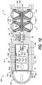
- FIG. 12 is a cross-sectional view of a bottom-fire perforating drone according to an exemplary embodiment
- FIG. 13A is a plan view from the tip section of the exemplary bottom fire drone according to claim 12 ;
- FIG. 13B is a cross-sectional view of the bottom-fire perforating drone according to FIG. 12 , taken along the plane by view ‘A’ according to FIG. 13A ;
- FIG. 14A shows an exemplary shaped charge for use with the exemplary bottom-fire perforating drone shown in FIG. 12 ;
- FIG. 14B shows a non-cross-sectional view of the exemplary shaped charge according to FIG. 14A ;
- FIG. 15 shows a blown-up view of the shaped charges received in the exemplary perforating gun assembly section according to FIG. 12 .
- the exemplary bottom-fire perforating drone 100 is a generally (though not literally or limitingly) torpedo-shaped assembly or module with a circumferential aspect c formed about a longitudinal axis x.
- the bottom-fire perforating drone 100 includes a tip section 195 at a front (downstream) end 101 of the bottom-fire perforating drone 100 and a tail section 180 at a rear (upstream) end 102 , opposite the front end 101 , of the bottom-fire perforating drone 100 .
- a perforating assembly section 110 and a control module section 130 are respectively positioned between the tail section 180 and the tip section 195 .
- the control module section 130 is connected at a first end 135 of the control module section 130 to the tip section 195 and at a second end 136 , opposite the first end 135 , of the control module section 130 to a downstream end 111 of the perforating assembly section 110 .
- the perforating assembly section 110 includes an upstream end 112 opposite the downstream end 111 and in the exemplary embodiment shown in FIG. 2A and FIG. 2B the upstream end 112 of the perforating assembly section 110 is connected to the tail section 180 .
- the tail section 180 may include guiding fins 181 for providing radial stability as the bottom-fire perforating drone 100 is traveling through a wellbore fluid within a wellbore.
- one or more of the tip section 195 , the control module section 130 , the perforating assembly section 110 , and the tail section 180 may have features such as guiding fins, a curved topology, etc. for providing one or more of rotational speed, radial stability, and reduced friction to the bottom-fire perforating drone 100 .
- each of the “tip section”, “control module section”, “perforating assembly section”, and “tail section” is defined with respect and reference to, and to aid in the description of, the position and configuration of certain structures and componentry of the exemplary embodiments of a bottom-fire perforating drone as described throughout this disclosure. None of the terms “tip section”, “control module section”, “perforating assembly section”, or “tail section” is limited to any particular assembly, configuration, or delineation points of, or along, a bottom-fire perforating drone according to this disclosure.
- any or all of the “tip section”, “control module section”, “perforating assembly section”, and “tail section” may be integrally formed by injection molding, casting, 3D printing, 3D milling from bar stock, etc.
- “integral” or “integrally formed” respectively means a single piece or formed as a single piece.
- connection generally means joined, such as by mechanical features, adhesives, welding, friction fit, or other known techniques for joining separate components, and may also mean “integrally formed” as that term is used in this disclosure, except where otherwise indicated.
- upstream means in a direction towards the wellbore entrance or surface and “downstream” means in a direction deeper or further into the wellbore.
- downstream means in a direction towards the wellbore entrance or surface
- downstream means in a direction deeper or further into the wellbore.
- the tip section 195 is positioned first in the wellbore fluid, the tip section 195 being positioned downstream of the tail section 180 .
- the bottom-fire perforating drone 100 is deployed and conveyed through the wellbore fluid via known techniques including, but not limited to, pump down conveyance.
- the exemplary perforating assembly section 110 is generally defined by a perforating assembly section body 119 that is configured for, among other things, retaining one or more shaped charges 113 and a detonating cord 160 for delivery downhole in a wellbore.
- the perforating assembly section 110 is generally cylindrically-shaped and is formed about the longitudinal axis x.
- the perforating assembly section 110 includes a plurality of shaped charges 113 , and each shaped charge 113 is positioned and retained, in part, in a first opening 115 of an aperture 114 that extends laterally through the perforating assembly section 110 along an axis y.
- the aperture extends between the first opening 115 on a first side 117 of the perforating assembly section 110 and a second opening 116 on a second side 118 , opposite the first side 117 , of the perforating assembly section 110 .
- the first side 117 of the perforating assembly section 110 and the second side 118 of the perforating assembly section 110 are defined separately for each of the plurality of apertures 114 , according to the respective opposing portions of the perforating assembly section 110 through which a particular aperture 114 passes.
- the fixation assembly 200 may also secure the detonating cord 160 in place at each shaped charge 113 along a length L of the perforating assembly section 110 , as described in detail with respect to FIGS. 5A-5E .
- the exemplary bottom-fire perforating drone 100 also includes, among other things, features such as charging/programming contacts 1800 for charging a power source and/or programming onboard circuitry contained in a control module 137 ( FIG. 2B ) of the bottom-fire perforating drone 100 and a ballistic interrupt actuator 460 for moving a ballistic interrupt 140 ( FIG. 2B ) between a closed state 143 ( FIG. 3A ) and an open state 144 ( FIG. 3B ) within the bottom-fire perforating drone 100 .
- charging/programming contacts 1800 for charging a power source and/or programming onboard circuitry contained in a control module 137 ( FIG. 2B ) of the bottom-fire perforating drone 100
- a ballistic interrupt actuator 460 for moving a ballistic interrupt 140 ( FIG. 2B ) between a closed state 143 ( FIG. 3A ) and an open state 144 ( FIG. 3B ) within the bottom-fire perforating drone 100 .
- FIGS. 3A and 3B each of those figures shows, among other things, a cross-section of the exemplary control module section 130 of the bottom-fire perforating drone 100 as generally described with respect to FIG. 2A and FIG. 2B .
- FIG. 3A shows the exemplary bottom-fire perforating drone 100 with the ballistic interrupt 140 in a closed state 143
- FIG. 3B shows the exemplary bottom-fire perforating drone 100 ′ with the ballistic interrupt in an open state 144 .
- the exemplary control module section 130 is generally defined by a control module section body 191 and is circumferentially-shaped and formed about the longitudinal axis x.
- the control module section 130 defined by the control module section body 191 has a profile including, among other things, a large diameter portion 193 with a diameter d 1 , a reduced diameter portion 194 with a diameter d 2 , a transition region 197 positioned between the large diameter portion 193 and the reduced diameter portion 194 , and a tapered portion 196 with a diameter d 3 at a position 196 ′ representing any particular point along the varying-diameter tapered portion 196 at which the diameter d 3 is measured.
- the diameter d 1 of the large diameter portion 193 is greater than the diameter d 2 of the reduced diameter portion 194 .
- the diameter d 2 of the reduced diameter portion 194 is substantially equal to a diameter d 7 of the perforating assembly section 110 .
- the transition region 197 is connected to each of the large diameter portion 193 and the reduced diameter portion 194 and spans a space therebetween.
- the presence and profile of the transition region 197 is not limited by the disclosed embodiments and may take any shape or configuration as particular applications dictate.
- the tapered portion 196 is positioned and spans a gap between the large-diameter portion 194 of the control module section 130 and the tip section 195 , and the diameter d 3 at the position 196 ′ on the tapered portion 196 gradually decreases in a direction v from the large-diameter portion 194 of the control module section 130 towards the tip section 195 .
- the tip section 195 may have a different profile, for example and without limitation, an arrow-like or pointed tip.
- each of the “large diameter portion 193 ”, “reduced diameter portion 194 ”, “transition region 197 ”, and “tapered portion 196 ” is defined with respect and reference to, and to aid in the description of, the profile of the exemplary control module section 130 shown in, e.g., FIGS. 3A and 3B .
- None of the terms “large diameter portion 193 ”, “reduced diameter portion 194 ”, “transition region 197 ”, or “tapered portion 196 ” is limited to any particular assembly, configuration, or delineation points of, or along, a bottom-fire perforating drone according to this disclosure, nor is a control module section according to this disclosure limited to a profile including one or more diameters.
- the control module section 130 may be cylindrically shaped with a constant diameter, or may have a non-circumferential profile.
- the control module section 130 defined by the control module section body 191 includes, among other things, a hollow interior portion 132 and a ballistic channel 141 respectively positioned within the control module section 130 defined by the control module section body 191 .
- the ballistic channel 141 is open to the hollow interior portion 132 and extends from the hollow interior portion 132 in a direction v′ from the hollow interior portion 132 towards the perforating assembly section 110 /tail section 180 .
- the ballistic channel 141 is surrounded by a portion 192 of increased thickness of the control module section body 191 and has a diameter d 4 that is smaller than a diameter d 5 of the hollow interior portion 132 .
- the diameter d 4 of the ballistic channel 141 is sized to receive a receiver booster 150 which, as shown in FIGS. 3A-4 , is positioned within the ballistic channel 141
- the ballistic interrupt 140 is positioned within the ballistic channel 141 in a ballistic interrupt cavity 146 that is formed as an area of the ballistic channel 141 with a diameter d 8 which is larger than the diameter d 4 of the ballistic channel 141 .
- the ballistic interrupt 140 and the receiver booster 150 are positioned in a spaced apart relationship within the ballistic channel 141 such that the ballistic interrupt 140 is nearer the hollow interior portion 132 and the receiver booster 150 is nearer the perforating assembly section 110 .
- the receiver booster 150 is connected to the detonating cord 160 , for example by crimping, within the ballistic channel 141 , and the exemplary ballistic channel 141 shown in, e.g., FIGS. 3A-4 , is sized to receive at least a portion of the detonating cord 160 .
- the detonating cord 160 extends away from the receiver booster 150 in the direction v′ towards the perforating assembly section 110 /tail section 180 , and opposite the direction v towards the ballistic interrupt 140 .
- a set of stackable pellets may be used in conjunction with, or in place of, the receiver booster 150 for initiating the detonating cord 160 by ballistic force.
- the control module section 130 and the hollow interior portion 132 are sized to receive the control module 137 which is positioned within the hollow interior portion 132 of the control module section 130 .
- the control module 137 includes a housing 138 that defines an inner area 320 of the control module 137 and encloses, for example and without limitation, a detonator 133 , a donor charge 134 , and a control assembly 131 .
- the control module 137 and the control assembly 131 are further shown and described with respect to FIG. 12 . With continuing reference to FIGS.
- the control assembly 131 may include controlling and operational components of the bottom-fire perforating drone 100 , such as, without limitation, a power source/battery, sensors, depth correlation device, programmable electronic circuit, trigger circuit, detonator fuse, etc.
- a power source/battery may also be positioned within the hollow interior portion 132 , itself, as may other components that do not necessarily need the isolation or component assemblies within the inner area 320 of the control module 137 . These and other components are discussed in additional detail with respect to the operation of the bottom-fire perforating drone 100 .
- control module 137 allows it to be removed/removable from the bottom-fire perforating drone 100 during transport, e.g., to comply with regulatory requirements, and quickly loaded into the bottom-fire perforating drone 100 at a wellsite.
- the inner area 320 of the control module 137 can be completely or partially hollow, or not hollow at all, depending on the layout of the control module components and the requirements for sealing the control module 137 .
- the control module 137 is pressure sealed to protect the components within the control module 137 from environmental conditions both outside of and within the wellbore.
- control module 137 may include various known seals to protect the control module 137 and the components within the control module 137 , components within the hollow interior portion 132 , or other components within the control module section 130 generally.
- an electrical selective sequence signal may be sent from, e.g., the programmable electronic circuit to the detonator 133 to initiate the detonator when the bottom-fire perforating drone 100 reaches at least one of a threshold pressure, temperature, horizontal orientation, inclination angle, depth, distance traveled, rotational speed, and position within the wellbore.
- the threshold conditions may be measured by any known devices consistent with this disclosure including a temperature sensor, a pressure sensor, a positioning device as a gyroscope and/or accelerometer (for horizontal orientation, inclination angle, and rotational speed), and a correlation device such as a casing collar locator (CCL) or position determining system (for depth, distance traveled, and position within the wellbore) as discussed below with respect to FIGS. 6A-9 and FIG. 12 .
- a temperature sensor for a pressure sensor
- a positioning device as a gyroscope and/or accelerometer (for horizontal orientation, inclination angle, and rotational speed)
- a correlation device such as a casing collar locator (CCL) or position determining system (for depth, distance traveled, and position within the wellbore) as discussed below with respect to FIGS. 6A-9 and FIG. 12 .
- the electrical selective sequence signal may include one or more of an addressing signal for activating one or more power components of the detonator 133 , an arming signal for activating a detonator firing assembly such as a trigger circuit or capacitor, and a detonating signal for detonating the detonator 133 .
- the threshold values and other instructions for addressing, arming, and/or detonating the detonator 133 may be taught to the programmable electronic circuit by, for example and without limitation, a control unit at a factory or assembly location or at the surface of the wellbore prior to deploying the bottom-fire perforating drone 100 into the wellbore.
- the selective sequence signal may be one or more digital codes including or more digital codes uniquely configured for the detonator 133 of each particular bottom-fire perforating drone 100 .
- FIG. 6A is a cross-section of an ultrasonic transducer 1400 that may be used in a system and method of determining location along a wellbore 2016 .
- the transducer 1400 may include a housing 1410 and a connector 1402 ; the connector 1402 is the portion of the housing 1410 allowing for connections to, e.g., the programmable electronic circuit that may generate and interpret the ultrasound signals.
- the key elements of the transducer 1400 are a transmitting element 1404 and a receiving element 1406 that are contained in the housing 1410 . In the transducer shown in FIG. 6A , the transmitting element 1404 and the receiving element 1406 are integrated into a single active element 1414 .
- the active element 1414 is configured to both transmit an ultrasound signal and receive an ultrasound signal.
- Electrical leads 1408 are connected to electrodes on the active element 1414 and convey electrical signals to/from the programmable electronic circuit.
- An electrical network 1420 may be connected between the electrical leads 1408 .
- Optional elements of a transducer include a sleeve 1412 , a backing 1416 and a cover/wearplate 1422 protecting the active element 1414 .
- FIG. 6B is a cross-section of an alternative version of an ultrasonic transducer 1400 ′ that may be used in a system and method of determining location along a wellbore 2016 .
- the transducer 1400 ′ may include a housing 1410 ′ and a connector 1402 ′; the connector 1402 ′ is the portion of the housing 1410 ′ allowing for connections to, e.g., the programmable electronic circuit that may generate and interpret the ultrasound signals.
- the key elements of the transducer 1400 ′ are a transmitting element 1404 ′ and a receiving element 1406 ′ that are contained in the housing 1410 ′.
- a delay material 1418 and an acoustic barrier 1417 are provided for improving sound transmission and receipt in the context of a separate transmitting element 1404 ′ and receiving element 1406 ′ apparatus.
- an exemplary bottom-fire perforating drone 1510 as part of an ultrasonic transducer system 1500 for determining the speed of the bottom-fire perforating drone 1510 traveling down a wellbore 2016 by identifying ultrasonic waveform changes is shown.
- the bottom-fire perforating drone 1510 may be equipped with one or more ultrasonic transducers 1530 , 1532 .
- the bottom-fire perforating drone 1510 has a first transducer 1530 (also marked T 1 ) and a second transducer 1532 (also marked T 2 ), one at each end of the bottom-fire perforating drone 1510 .
- the distance separating the first transducer 1530 from the second transducer 1532 is a constant and may be referred to as distance ‘Z’.
- Each of the first transducer 1530 and the second transducer 1532 may have a transmitting element 1404 and a receiving element 1406 (as shown in FIGS. 6A and 6B ) that sends/receives signals radially from the bottom-fire perforating drone 1510 .
- each transmitting element 1404 and receiving element 1406 may be disposed about an entire radius of the bottom-fire perforating drone 1510 ; such an arrangement permits the transmitting element 1404 and the receiving element 1406 respectively to send and receive signals about essentially the entire radius of the bottom-fire perforating drone 1510 .
- the exemplary bottom-fire perforating drone 1510 shown in FIG. 7 includes the first ultrasonic transceiver 1530 and the second ultrasonic transceiver 1532 .
- Each of the first ultrasonic transceiver 1530 and the second ultrasonic transceiver 1532 is capable of detecting alterations in the medium through which the bottom-fire perforating drone 1510 is traversing by transmitting an ultrasound signal 1526 , 1526 ′ and receiving a return ultrasound signal 1528 , 1528 ′.
- T 2 1532 is axially displaced from T 1 1530 along the long axis of the bottom-fire perforating drone 1510 , T 2 1532 passes through an anomaly in the wellbore 2016 at a different time than T 1 1530 as the bottom-fire perforating drone 1510 traverses the wellbore 2016 .
- T 1 1530 and T 2 1532 pass the anomalous point 1506 in wellbore 1070 at slightly different times.
- T 1 1530 and T 2 1532 both register a sufficiently strong and identical, i.e., repeatable, modified return signal as a result of an anomaly at the anomalous point 1506 , it is possible to determine the time difference between T 1 1530 registering the anomaly at the anomalous point 1506 and T 2 1532 registering the same anomaly.
- the distance Z between T 1 1530 and T 2 1532 being known, a sufficiently precise measurement of time between T 1 1530 and T 2 1532 passing a particular anomaly provides a measure of the velocity of the bottom-fire perforating drone 1510 , i.e., velocity equals change in position divided by change in time.
- the velocity of the bottom-fire perforating drone 1510 through the wellbore 2016 is available every time the bottom-fire perforating drone 1510 passes an anomaly that returns a sufficient change in amplitude of a return signal for each of T 1 1530 and T 2 1532 .
- a navigation system 1600 such as used in the ultrasonic transducer system 1500 shown in FIG. 7
- two wire coils 1632 , 1634 are respectively used with the transceivers 1530 , 1532 .
- a signal generating and processing unit 1640 is attached to both ends of a first coil 1632 wrapped around a first core 1622 of high magnetic permeability material and a second coil 1634 wrapped around a second core 1624 of high magnetic permeability material.
- the cores 1622 , 1624 and the coils 1632 , 1634 are presented in FIG. 8 as toroidal in shape, other shapes are possible.
- the exemplary ultrasonic transducer system 1500 may register the same anomaly, i.e., change in magnetic permeability, once for each coil 1632 , 1634 . In this configuration, having the coils 1632 , 1634 disposed on the same plane may achieve this result.
- the processing unit 1640 may include an oscillator circuit 1644 and a capacitor 1642 .
- An oscillating signal is generated by the oscillator circuit 1644 , and sent to the wire coils 1632 , 1634 .
- the wire coils 1632 , 1634 acting as inductors, a magnetic field is established around the wire coils 1632 , 1634 when charge flows through the wire coils 1632 , 1634 .
- Insertion of the capacitor 1642 in the processing unit 1640 results in constant transfer of electrons between the wire coils/inductors 1632 , 1634 and the capacitor 1642 , i.e., in a sinusoidal flow of electricity between the wire coils 1632 , 1634 and the capacitor 1642 .
- the frequency of this sinusoidal flow will depend upon the capacitance value of the capacitor 1642 and the magnetic field generated around the wire coils 1632 , 1634 , i.e., the inductance value of the wire coils 1632 , 1634 .
- the peak strength of the sinusoidal magnetic field around the wire coils 1632 , 1634 will depend on the materials immediately external to the wire coils 1632 , 1634 .
- the circuit With the capacitance of the capacitor 1642 being constant and the peak strength of the magnetic field around the wire coils 1632 , 1634 being constant, the circuit will resonate at a particular frequency. That is, current in the circuit will flow in a sinusoidal manner having a frequency, referred to as a resonant frequency, and a constant peak current.
- the bottom-fire perforating drone 1700 may take the form of the bottom-fire perforating drone 100 shown in FIGS. 2A-3B .
- the body portion 1710 of the bottom-fire perforating drone 1700 may bear one or more shaped charges.
- detonation of the shaped charges is typically initiated with an electrical pulse or signal supplied to a detonator.
- the detonator 133 may initiate the shaped charges either directly or through an intermediary structure such as a detonating cord.
- a power supply 1792 may be included generally as part of the bottom-fire perforating drone 1700 in any portion such as configurations dictate. It is contemplated that the power supply 1792 may be disposed so that it is adjacent any components of the bottom-fire perforating drone 1700 that require electrical power (such as an onboard computer 390 ).
- the on-board power supply 1792 for the bottom-fire perforating drone 1700 may take the form of an electrical battery; the battery may be a primary battery or a rechargeable battery. Whether the power supply 1792 is a primary or rechargeable battery, it may be inserted into the bottom-fire perforating drone 1700 at any point during construction of the bottom-fire perforating drone 1700 or immediately prior to insertion of the bottom-fire perforating drone 1700 into the wellbore 2016 . If a rechargeable battery is used, it may be beneficial to charge the battery immediately prior to insertion of the bottom-fire perforating drone 1700 into the wellbore 2016 . Charge times for rechargeable batteries are typically on the order of minutes to hours.
- a capacitor is an electrical component that consists of a pair of conductors separated by a dielectric. When an electric potential is placed across the plates of a capacitor, electrical current enters the capacitor, the dielectric stops the flow from passing from one plate to the other plate and a charge builds up. The charge of a capacitor is stored as an electric field between the plates.
- Each capacitor is designed to have a particular capacitance (energy storage). In the event that the capacitance of a chosen capacitor is insufficient, a plurality of capacitors may be used. When a capacitor is connected to a circuit, a current will flow through the circuit in the same way as a battery.
- a supercapacitor operates in a similar manner to a capacitor except there is no dielectric between the plates. Instead, there is an electrolyte and a thin insulator such as cardboard or paper between the plates. When a current is introduced to the supercapacitor, ions build up on either side of the insulator to generate a double layer of charge.
- the structure of supercapacitors allows only low voltages to be stored, this limitation is often more than outweighed by the very high capacitance of supercapacitors compared to standard capacitors. That is, supercapacitors are a very attractive option for low voltage/high capacitance applications as will be discussed in greater detail hereinbelow. Charge times for supercapacitors are only slightly greater than for capacitors, i.e., minutes or less.
- a battery typically charges and discharges more slowly than a capacitor due to latency associated with the chemical reaction to transfer the chemical energy into electrical energy in a battery.
- a capacitor is storing electrical energy on the plates so the charging and discharging rate for capacitors are dictated primarily by the conduction capabilities of the capacitors plates. Since conduction rates are typically orders of magnitude faster than chemical reaction rates, charging and discharging a capacitor is significantly faster than charging and discharging a battery.
- batteries provide higher energy density for storage while capacitors have more rapid charge and discharge capabilities, i.e., higher power density, and capacitors and supercapacitors may be an alternative to batteries especially in applications where rapid charge/discharge capabilities are desired.
- the on-board power supply 1792 for the bottom-fire perforating drone 1700 may take the form of a capacitor or a supercapacitor, particularly for rapid charge and discharge capabilities.
- a capacitor may also be used to provide additional flexibility regarding when the power supply is inserted into the bottom-fire perforating drone 1700 , particularly because the capacitor will not provide power until it is charged.
- shipping and handling of the bottom-fire perforating drone 1700 containing shaped charges or other explosive materials presents low risks where an uncharged capacitor is installed as the power supply 1792 . This is contrasted with shipping and handling of a bottom-fire perforating drone 1700 with a battery, which can be an inherently high risk activity and frequently requires a separate safety mechanism to prevent accidental detonation.
- the act of charging a capacitor is very fast.
- the capacitor or supercapacitor being used as a power supply 1792 for the bottom-fire perforating drone 1700 can be charged immediately prior to deployment of the bottom-fire perforating drone 1700 into the wellbore 2016 .
- magnetic sensors such as Hall effect magnetic sensors or magnetometers may be used in combination with a super capacitor as a depth correlation sensor in the exemplary bottom-fire perforating drones described herein.
- a system may be used with a magnetic ring (e.g., a plastic with flexible magnetic tape or film secured thereto) between adjacent wellbore casings, for example, at a collar between casing ends, wherein the magnetic ring includes beacons or magnets for detection by the drone sensors.
- casing collars may be painted with high temperature paint or adhesives including magnetic material such as metal fillings, powder, or flakes.
- Electrochemical potential is often not a simple, convenient or failsafe thing to measure in a battery. It may be the case that the potential that a ‘charged’ battery may be mistaken for an ‘uncharged’ battery simply cannot be reduced sufficiently to allow for shipping the bottom-fire perforating drone 1700 with an uncharged battery.
- the time for charging a rechargeable battery having adequate power for the bottom-fire perforating drone 1700 could be on the order of an hour or more.
- fast recharging batteries of sufficient charge capacity are uneconomical for the ‘one-time-use’ or ‘several-time-use’ that would be typical for batteries used in the bottom-fire perforating drone 1700 .
- electrical components of an exemplary bottom-fire perforating drone as described throughout this disclosure including the control module 137 , an oscillator circuit 1644 , one or more wire coils 1632 , 1634 , and one or more ultrasonic transceivers 1530 , 1532 may be battery powered while explosive elements like the detonator for initiating detonation of the shaped charges are capacitor powered.
- Such an arrangement would take advantage of the possibility that some or all of the control module 137 , the oscillator circuit 1644 , the wire coils 1632 , 1634 , and the ultrasonic transceivers 1530 , 1532 may benefit from a high density power supply having higher energy density, i.e., a battery, while initiating elements such as detonators typically benefit from a higher power density, i.e., capacitor/supercapacitor.
- a very important benefit for such an arrangement is that the battery is completely separate from the explosive materials, affording the potential to ship the bottom-fire perforating drone 1700 preloaded with a charged or uncharged battery.
- the power supply that is connected to the explosive materials, i.e., the capacitor/supercapacitor may be very quickly charged immediately prior to dropping the bottom-fire perforating drone 1700 into wellbore 2016 .
- a capacitor used as a power supply in the exemplary bottom-fire drones described throughout this disclosure may be charged to 30-40 Amps, and/or charged for approximately 15-40 minutes per bottom-fire perforating drone, and provide approximately 1 hour of active power.
- the donor charge 134 is adjacent to and substantially aligned with the ballistic channel 141 , and a portion 139 of the control module housing 138 is positioned between the donor charge 134 and the ballistic channel 141 .
- adjacent means next to or near, but is not limited to directly abutting and does not exclude the presence of intervening structures.
- the ballistic interrupt 140 within the ballistic channel 141 is positioned in a spaced apart relationship between the donor charge 134 and the receiver booster 150 .
- the donor charge 134 is positioned within a detonator channel 145 within the control module 137 , and the detonator 133 is positioned adjacent to the donor charge 134 within the detonator channel 145 and substantially aligned with the donor charge 134 along the longitudinal axis x.
- the detonator 133 may be, for example and without limitation, an explosive charge or any other device as is well known in the art for causing a detonation, ignition, or ballistic initiation.
- the detonator 133 may be a selective detonator.
- selective means that the detonator 133 is initiated only when it receives a specific initiating signal or selective sequence signal, as discussed above, from the control module 137 (i.e., the programmable electronic circuit), e.g., to cause a capacitive discharge to a fuse of the detonator 133 .
- RF radio-frequency
- the donor charge 134 is also an explosive shaped charge, but the donor charge 134 may include, for example, an explosive material within a casing (not numbered), designed to create a directed perforating jet upon detonation, as is well known in the art. According to the exemplary configuration, detonating the detonator 133 will cause the donor charge 134 to detonate.
- the ballistic interrupt 140 is thus an important safety and operational feature of the bottom-fire perforating drone 100 .
- the donor charge 134 when detonated it produces the perforating jet that pierces the portion 139 of the control module housing 138 between the donor charge 134 and the ballistic channel 141 , and travels into the ballistic channel 141 .
- the ballistic interrupt 140 When the ballistic interrupt 140 is in the closed state 143 shown in FIG. 3A , it provides a physical barrier and thereby prevents the perforating jet created by the donor charge 134 from reaching the receiver booster 150 and thereby initiating detonation (as explained further below) of the bottom-fire perforating drone 100 .
- the ballistic interrupt 140 includes a through-bore 142 that extends through the ballistic interrupt 140 between a first opening 142 a of the through-bore 142 and a second opening 142 b of the through-bore 142 .
- the through-bore 142 is substantially perpendicular to the longitudinal axis x and the ballistic interrupt 140 otherwise prevents ballistic communication between the donor charge 134 and the receiver booster 150 by shielding the receiver booster 150 from the perforating jet created by the donor charge 134 .
- the ballistic interrupt 140 in the closed state 143 does not provide a path through which the perforating jet created by the donor charge 134 may reach the receiver booster 150 and thus is no longer ballistically aligned with the donor charge 134 .
- the first opening 142 a and the second opening 142 b of the through-bore 142 may be positioned within an area of the ballistic interrupt cavity 146 at the diameter d 5 which is beyond the diameter of the ballistic channel 141 and may enhance the shielding effect of the ballistic interrupt 140 .
- the ballistic interrupt 140 may include additional holes therethrough and/or in communication with the through-bore 142 , for preventing failure or collapse of the bottom-fire perforating drone 100 due to a pressure differential across the ballistic interrupt 140 .
- the detonator 133 may be spaced apart from the donor charge 134 .
- a donor charge may be positioned in the ballistic channel 141 or in the through-bore 142 of the ballistic interrupt 140 .
- the detonator 133 would provide sufficient ballistic energy to reach the spaced-apart donor charge, which may include, e.g., penetrating the portion 139 of the control module housing 138 between the detonator channel 145 and the ballistic channel 141 .
- the ballistic energy of the detonator 133 would be insufficient to initiate the donor charge through the ballistic interrupt 140 in the closed state 143 .
- the safety control provided by the ballistic interrupt 140 would not be compromised.
- the ballistic interrupt 140 is moved to the open state 144 as shown in FIG. 3B .
- the through-bore 142 is substantially parallel to the longitudinal axis x and coaxial with the ballistic channel 141 .
- the through-bore 142 in the open state 144 allows ballistic communication via the through-bore 142 between the donor charge 134 and the receiver booster 150 such that the perforating jet created by the donor charge 134 may reach the receiver booster 150 , causing the receiver booster 150 to detonate when subject to the perforating jet.
- the receiver booster 150 is generally an explosive charge or any other device, as is well known in the art, for causing an explosion, initiation, or ballistic force, including encapsulated receiver boosters and receiver boosters in a pressure sealed housing 151 . Detonation of the receiver booster 150 initiates the detonating cord 160 which is further connected to and configured for detonating the shaped charges 113 , as is generally known and explained in additional detail with respect to FIG. 5A .
- the pressure sealed housing 151 of the receiver booster 150 may further extend to, or a separate pressure sealed housing may be used for, the connection between the receiver booster 150 and the detonating cord 160 .
- the pressure sealed housing 151 may be rated to at least 10,000 psi and, for exemplary uses, to at least between 15,000 psi and 20,000 psi to enhance waterproof capability.
- a small amount of grease may be used at a crimp connection between the receiver booster 150 and the detonating cord 160 to prevent water invasion into the connection.
- internal contours of the bottom-fire perforating drone 100 e.g., the configuration of the ballistic channel 141 , may be conformed closely to the contour(s) of the receiver booster 150 and the detonating cord 160 , including any housings, caps, or sealing mechanisms thereon, to decrease the area through which fluid may encounter the components/connections.
- the receiver booster 150 may be enlarged relative to the detonating cord 160 to prevent an initial bend or curve in the detonating cord 160 which may interfere with assembly of the detonating cord 160 to the receiver booster 150 and result in nicks or crimps in the detonating cord 160 .
- the detonating cord 160 may be energetically coupled to the receiver booster 150 by engaging a lower end of the receiver booster 150 or being placed in a side-by-side configuration with the receiver booster 150 .
- the ballistic interrupt 140 is movable between the closed state 143 and the open state 144 using, for example, a mechanical key as part of a control system at the surface of the wellbore.
- the ballistic interrupt 140 includes a ballistic interrupt actuator 460 that is part of or in operable connection with the ballistic interrupt 140 , for example when the ballistic interrupt 140 is cylindrical and extends laterally through the bottom-fire perforating drone 100 , and is received in an opening 462 in the control module section body 191 .
- the ballistic interrupt actuator 460 includes a keyway 461 for receiving the mechanical key (not shown).
- the mechanical key may rotate the keyway 461 using a rotational force, thereby rotating the ballistic interrupt 140 between the closed state 143 and the open state 144 (or vice versa).
- the ballistic interrupt 140 is substantially cylindrically-shaped or spherically shaped and is rotatable between the closed state 143 and the open state 144 (and vice versa).
- the ballistic interrupt 140 including the ballistic interrupt actuator 460 is further shown and described with respect to FIG. 12 .
- the ballistic interrupt 140 may take any shape or configuration consistent with this disclosure, i.e., movable between a closed state and an open state.
- the ballistic interrupt 140 may also be moved by other mechanical techniques and using other configurations of a ballistic interrupt actuator and mechanical engagement or otherwise, such as a socket-nut engagement or pin-slot engagement, or may be movable via a magnetic engagement, or via a tool that extends through the control module section body 191 and directly engages the ballistic interrupt 140 .
- FIG. 4 shows, among other things, an exploded, cross-sectional view of the control module section 130 of the exemplary bottom-fire perforating drone 100 .
- the control module 137 is shown removed from the hollow interior 132 of the control module section 130 and an opening 147 from the ballistic channel 141 into the hollow interior portion 132 is visible. It is through the opening 147 that a perforating jet created by the donor charge 134 travels into the ballistic channel 141 and, if the ballistic interrupt 140 is in the open state 144 , through the through-bore 142 , and ultimately arrives at the receiver booster 150 to initiate the detonating cord 160 that is attached to the receiver booster 150 .
- the detonating cord 160 extends away from the receiver booster 150 in the direction v′ towards, e.g., the perforating assembly section 110 and the shaped charges 113 positioned therein.
- the detonating cord 160 may be any known detonating cord that is pressure and temperature resistant to downhole conditions.
- a conversion region 330 guides the detonating cord 160 to a connecting portion 410 ( FIGS. 5A, 5B, and 5E ) including a detonating cord slot 411 of a first shaped charge 113 , i.e., the shaped charge 113 nearest the control module section 130 , via a guiding slot 310 formed as a radial cutaway in the conversion region 330 .
- the conversion region 330 in the exemplary embodiment shown in FIG.
- the perforating assembly section 110 and the control module section 130 are generally defined with respect and reference to the position and configuration of certain structures and componentry and for aiding the description of an exemplary bottom-fire perforating drone according to this disclosure.
- control module section 130 is the length M of the bottom-fire perforating drone 100 along or within which, without limitation, control components (e.g., the control module 137 ) and initiation components (e.g., the detonator 133 , the donor charge 134 , the ballistic interrupt 140 , and the receiver booster 150 ) are positioned.
- control components e.g., the control module 137
- initiation components e.g., the detonator 133 , the donor charge 134 , the ballistic interrupt 140 , and the receiver booster 150
- the conversion region 330 in the exemplary embodiment shown in FIG. 4 joins and transitions a configuration of the control module section 130 on a first side 331 of the conversion region 330 to a configuration of the perforating assembly section 110 on a second side 332 of the conversion region 330 .
- FIGS. 5A-5E a shaped charge 400 and the fixation assembly 200 for retaining the shaped charge 400 in the perforating assembly section 110 according to an exemplary embodiment are shown.
- FIG. 5A shows a breakout of the shaped charge 400 and a fixation connector 120 (described below) from the exemplary bottom-fire perforating drone 100 and fixation assembly 200 as shown and described with respect to FIGS. 2A-4 .
- FIG. 5B shows the exemplary shaped charge 400 for use in the embodiment shown in FIG. 5A .
- FIGS. 5C-5E show blown-up views of the exemplary fixation assemblies 200 in various stages of assembly with the exemplary shaped charge 400 and detonating cord 160 .
- the exemplary shaped charge 400 includes, among other things, an initiation side 401 at which the detonating cord 160 , for example, will attach to detonate the shaped charge 400 , and an encapsulated side 402 opposite the initiation side 401 and including a cap 403 for enclosing explosive and/or kinetic materials (not shown) within a casing 404 of the shaped charge 400 , as is well known in the art.
- the exemplary shaped charges 400 include a cap 403 because the shaped charges 113 , 400 in the disclosed exemplary embodiments of a bottom-fire perforating drone 100 are exposed—i.e., they are not otherwise isolated from wellbore conditions by a structure of the bottom-fire perforating drone 100 .
- Wellbore fluids and conditions may be corrosive, excessively hot and high pressure, turbulent, and/or otherwise damaging to the shaped charges 113 , 400 , especially in the event that wellbore fluid or high pressures permeate into the shaped charge casing 404 .
- Encapsulated shaped charges are generally known for such exposed applications.
- a bottom-fire perforating drone may have a configuration for enclosing associated shaped charges and thereby obviating the need for encapsulated shaped charges.
- the connecting portion 410 of the exemplary shaped charge 400 is positioned at the initiation side 401 of the shaped charge 400 and may be integrally formed with the casing 404 as a projection therefrom.
- the exemplary connecting portion 410 shown in FIG. 5A and FIG. 5B is configured generally as a cylinder with the detonating cord slot 411 , i.e., a parabolic void, extending between a bottom surface 121 of the connecting portion 410 and a detonating cord seat 415 within the cylinder.
- the detonating cord slot 411 and the detonating cord seat 415 may be shaped complimentarily to the detonating cord 160 or may include any configuration consistent with retaining and guiding the detonating cord 160 between shaped charges 400 along the length L of the bottom-fire perforating drone 100 , as described herein.
- the shaped charge 400 and the connecting portion 410 are configured and sized such that the connecting portion 410 and an external threaded portion 412 of the connecting portion 410 protrude from a central aperture 171 of the fixation assembly 200 when the shaped charge 400 is received in the aperture 114 through the perforating assembly section 110 .
- the central aperture 171 defines, in part, the second opening 116 of the aperture 114 through the perforating assembly section 110 .
- This configuration provides a connection area for the fixation connector 120 to engage the connecting portion 410 of the shaped charge 400 and clamp, compress, or otherwise secure the connecting portion 410 at the second opening 116 , thereby securing, at least in part, the shaped charge 400 in the aperture 114 .
- the fixation connector 120 is an annular, female connector with a threaded inner surface 420 and an annular opening 421 .
- the threaded inner surface 420 of the fixation connector 120 is complimentary to the external threaded portion 412 of the connecting portion 410 of the shaped charge 400 , for threadingly engaging the external threaded portion 412 of the connecting portion 410 when the connecting portion 410 is received within the annular opening 421 of the fixation connector 120 .
- the fixation connector 120 may then be threadingly advanced along the external threaded portion 412 of the connecting portion 410 until, e.g., it reaches and begins to compress against an opposing surface or structure of the fixation assembly 200 .
- the opposing structure includes a plurality of teeth 450 extending outwardly from a star-shaped plate 170 that will be further described with respect to the fixation assembly 200 .
- the fixation assembly 200 is not limited by the disclosed geometries or configurations.
- other known compression, connection, or retention devices and techniques including, without limitation, clamps, clasps, screws, nuts, ratcheting connectors, straps, bands, tape, rubber rings and the like may be used to fixate various exemplary shaped charges, in various exemplary bottom-fire perforating drone assemblies.
- the mechanisms, structures, and components of a particular fixation assembly may be separate or may be integrally formed with each other and/or the perforating assembly section body 119 as, for example, features of a single injection-molded piece.
- the star-shaped plate 170 in the exemplary fixation assembly 200 is integrally formed with the perforating assembly section body 119 , as a feature thereof.
- the star-shaped plate 170 is a generally circularly-shaped surface feature on the second side 118 of the perforating assembly section body 119 with respect to, and opposite, the first opening 115 of a corresponding aperture 114 through the perforating assembly section 110 , with which the star-shaped plate 170 is concentrically aligned.
- the star-shaped plate 170 may be a terminus of the aperture 114 .
- the star-shaped plate 170 is defined in part by an outer ring portion 174 from which a plurality of fingers 172 extend radially inwardly between the outer ring portion 174 and respective end portions 440 of each finger 172 .
- the end portions 440 are collectively positioned about the central aperture 171 in the star-shaped plate 170 and thereby define the central aperture 171 .
- the central aperture 171 extends laterally (e.g., along the axis y) through the star-shaped plate 170 between an outside of the bottom-fire perforating drone 100 and an interior (not numbered) of the aperture 114 through the perforating assembly section 110 .
- a plurality of gaps 173 extend radially outwardly from the central aperture 171 such that the fingers 172 and the gaps 173 are alternatingly arranged about a circumference of the central aperture 171 , thus creating the so-called “star-shaped” feature.
- the end portions 440 of some of the fingers 172 collectively include the plurality of teeth 450 that form a compression surface for the fixation connector 120 as described further herein with respect to an exemplary practice of the bottom-fire perforating drone 100 .
- Each of the teeth 450 is a projection that is connected to, or integral with, a respective end portion 440 and extends away from the end portion 440 at about a 90-degree angle to the finger 172 , in a direction away from the longitudinal axis x of the bottom-fire perforating drone 100 .
- the plurality of teeth 450 will extend along at least a portion of the connecting portion 410 of the shaped charge 400 that protrudes from the central aperture 171 of the star-shaped plate 170 when the shaped charge 400 is retained in the aperture 114 through the perforating assembly section 110 .
- each shaped charge 400 may be connected to the exemplary bottom-fire perforating drone 100 by inserting the shaped charge 400 into the corresponding aperture 114 through the perforating assembly section 110 .
- the connecting portion 410 including the external threaded portion 412 and the detonating cord slot 411 protrudes from the central aperture 171 in the star-shaped plate 170 , as described.
- the detonating cord 160 may then be inserted into the detonating cord slot 411 , down to the detonating cord seat 415 , and the fixation connector 120 may be threaded onto and advanced along the connecting portion 410 until it reaches the plurality of teeth 450 , against which it will compress and retain the shaped charge 400 and the detonating cord 160 .
- the exemplary configuration of the plurality of teeth 450 shown in FIGS. 5A and 5C-5E elevates the fixation connector 120 above the detonating cord 160 within the detonating cord slot 411 such that the fixation connector 120 may be sufficiently compressed against the plurality of teeth 450 to secure the shaped charge 400 without crushing the detonating cord 160 . Further, the compression is enhanced because the teeth 450 are positioned on the fingers 172 which have additional resiliency and may conform to oppose specific forces created by the fixation connector 120 .
- the configuration also allows the detonating cord 160 to extend along the length L of the perforating assembly section 110 through spaces (not numbered) created between the plurality of teeth 450 by end portions 440 that do not include teeth 450 .
- the shaped charge 400 may be oriented (e.g., turned) within the aperture 114 such that the detonating cord slot 411 is oriented to direct the detonating cord 160 towards a subsequent shaped charge 400 on the perforating assembly section 110 .
- the shaped charges 400 are arranged in a helical pattern along the length L, and the detonating cord 160 follows the helical pattern and connects to each of the shaped charges 400 .
- the detonating cord 160 in the assembled fixation assembly 200 is held in sufficient contact, communication, or proximity with the initiation end 401 of the shaped charges 400 such that the detonating cord 160 is energetically coupled to the initiation end 401 of each shaped charge 400 so as to detonate the explosive charge within the casing 404 , as is well known in the art.
- shaped charge apertures 114 (and correspondingly, the shaped charges 113 , 400 ) are shown in a typical helical arrangement about the perforating assembly section 110 in the exemplary embodiment shown in FIGS. 2A-5E , the disclosure is not so limited and it is contemplated that any arrangement of one or more shaped charges may be accommodated, within the spirit and scope of this disclosure, by the exemplary bottom-fire perforating drone 100 .
- a single shaped charge aperture or a plurality of shaped charge apertures for respectively receiving a shaped charge may be positioned at any phasing (i.e., circumferential angle) on the body portion, and a plurality of shaped charge apertures may be included, arranged, and aligned in any number of ways.
- the shaped charge apertures 114 may be arranged, with respect to the body portion, along a single longitudinal axis, within a single radial plane, in a staggered or random configuration, spaced apart along a length of the body portion, pointing in opposite directions, and the like.
- the bottom-fire perforating drone 110 including the perforating assembly section body 119 , the control module section body 191 , the tip section 195 , and the tail section 180 may be formed from a material that will substantially disintegrate upon detonation of the shaped charges 113 .
- the material may be an injection-molded plastic that will substantially dissolve into a proppant when the shaped charges 113 are detonated, and the bottom-fire perforating drone 100 may be an integral unit.
- one or more portions of the bottom-fire perforating drone 100 may be formed from a variety of techniques and/or materials including, for example and without limitation, injection molding, casting (e.g., plastic casting and resin casting), metal casting, 3D printing, and 3D milling from a solid plastic bar stock.
- injection molding e.g., plastic casting and resin casting
- metal casting e.g., metal casting, 3D printing, and 3D milling from a solid plastic bar stock.
- a bottom-fire perforating drone 100 is for aiding the disclosure with respect and reference to the position of various components, and forming the bottom-fire perforating drone 100 , for example, with one or a combination of integral and separate elements, may be done as applications dictate, without limitation based on the disclosed sections and portions of a bottom-fire perforating drone 100 .
- the bottom-fire perforating drone 100 may be formed as an integral unit, and a portion such as the tip section 195 according to this disclosure may then be removed and adapted for re-securing to the bottom-fire perforating drone 100 , to allow the bottom-fire perforating drone 100 to, e.g., be transported without a detonator assembly (such as in the control module 137 ) according to applicable regulations.
- the control module 137 may be inserted into, e.g., the control module section 130 according to this disclosure, and the tip section 195 re-secured thereto.
- the tip section 195 may be adapted for re-securing to the control module section 130 by milling, turning or injection molding complementary threaded portions, click slots or a bayonet key-turn in each, or using other techniques as known.
- the connection between the tip section 195 and the control module section is further shown and discussed with respect to FIG. 12 .
- the control module 137 may be preassembled in the control module section 130 , before transport, as applicable regulations and applications allow.
- a bottom-fire perforating drone 100 formed according to this disclosure leaves a relatively small amount of debris in the wellbore post perforation.
- at least a portion of the bottom-fire perforating drone 100 may be formed from plastic that is substantially depleted of other components including metals. Substantially depleted may mean, for example and without limitation, lacking entirely or including only nominal or inconsequential amounts.
- the plastic may be combined with any other materials consistent with this disclosure.
- the materials may include metal powders, glass beads or particles, known proppant materials, and the like that may serve as a proppant material when the shaped charges 113 are detonated.
- the materials may include, for example, oil or hydrocarbon-based materials that may combust and generate pressure when one or more of the detonator 133 , the donor charge 134 , and the shaped charges 113 are detonated, synthetic materials potentially including a fuel material and an oxidizer to generate heat and pressure by an exothermic reaction, and materials that are dissolvable in a hydraulic fracturing fluid.
- the exemplary bottom-fire perforating drone 100 may be connected at the tail portion 180 to a wireline that extends to the surface of the wellbore.
- the wireline may be connected to the bottom-fire perforating drone by any known technique for connecting a wireline to a wellbore tool.
- the wireline may further assist in retrieving any components of the bottom-fire perforating drone, including, without limitation, a control module, data collection device, or other portions that remain in the wellbore post detonation/perforation. The remaining components may be retracted to the surface along with the wireline.
- one or more bottom-fire perforating drones 100 are connected to a control system at the surface of a wellbore.
- the bottom-fire perforating drones 100 may be manually connected to the control system, or loaded into, for example and without limitation, a deployment vehicle, pressure equalization chamber, or other system for deploying the bottom-fire perforating drones 100 into the wellbore and including an appropriate connection to the control system.
- the control system may perform, among other things, a safety check and function test on each bottom-fire perforating drone 100 .
- the control system or an operator may “arm” the bottom-fire perforating drone 100 by moving the ballistic interrupt 140 to an open state 144 , as described.
- the control system may also record which bottom-fire perforating drones 100 have been armed and determine the order in which the respective bottom-fire perforating drones 100 will be deployed.
- the control system may communicate the order, and other instructions, to the bottom-fire perforating drone 100 via an electrical connection to the control assembly 131 , e.g., the programmable electronic circuit, of each bottom-fire perforating drone 100 as described.
- Other instructions may include, without limitation, a threshold depth at which to send a detonation signal to the detonator 133 , a time delay or other instructions for arming a trigger circuit, desired data to transmit to the wellbore surface, or other instructions that a control system may provide as discussed in United States Provisional Patent Application Nos. 62/690,314 filed Jun. 26, 2018 and 62/765,185 filed Aug. 20, 2018, both of which are incorporated herein by reference in their entirety.
- the control assembly 131 includes, without limitation, a depth correlation device, and the programmable electronic circuit is either pre-programmed, or programmed via the control system, to receive from the depth correlation device data regarding the current depth of the bottom-fire perforating drone 100 within the wellbore and send a detonation signal to the detonator 133 when the bottom-fire perforating drone 100 reaches a predetermined depth.
- the depth correlation device may be, for example, an electromagnetic sensor, an ultrasonic transducer, or other known depth correlation devices consistent with this disclosure.
- the bottom-fire perforating drone 100 may also include a velocity sensor for measuring a current velocity of the bottom-fire perforating drone 100 within the wellbore, or the depth correlation device may include a velocity sensor or calculate a velocity based on sequential depth readings, and the programmable electronic circuit may be programmed to receive such velocity data as part of a criteria for transmitting the detonation signal.
- the bottom-fire perforating drone 100 may work with other systems, such as radio-frequency (RF) transducers, casing collar locators (CCL), or other known systems for determining a position of a wellbore tool within the wellbore.
- RF radio-frequency
- CCL casing collar locators
- the depth correlation device measures the depth of the bottom-fire perforating drone 100 within the wellbore.
- the programmable electronic circuit sends a detonation signal to the detonator 133 , which initiates detonation of the donor charge 134 and ultimately the shaped charges 113 , as described.
- the programmable electronic circuit may be in wired, wireless, or contactable electrical communication with the detonator 133 by various known techniques, or may send the detonation signal via, or after activating, e.g., a trigger circuit or other intervening detonation component.
- the detonation signal may be, without limitation, a selective sequence signal, as previously discussed, that is unique to the detonator 133 of the particular bottom-fire perforating drone 100 .
- the selective detonation signal may provide a safety measure against accidental firing by, for example, external RF signals.
- the bottom-fire perforating drone 100 travels through the wellbore with the tip section 195 downstream, and the detonating cord 160 is initiated by the receiver booster 150 at the downstream end 111 of the perforating assembly section 110 .
- the ballistic/thermal release from the detonating cord 160 propagates along the length L of the perforating assembly section 110 in a direction from the downstream end 111 of the perforating assembly section 110 to the upstream end of the perforating assembly section 110 , and the shaped charges 113 are correspondingly detonated (by the detonating cord 160 ) in a bottom-up, i.e., downstream to upstream, sequence.
- This bottom-up sequence for detonating the shaped charges 113 prevents downstream shaped charges and portions of the bottom-fire perforating drone 100 from being separated and blown away from the rest of the assembly, as may happen if an upstream shaped charge is detonated while a drone is traveling at high velocity in a wellbore fluid. Accordingly, the bottom-up detonation sequence may prevent downstream shaped charges from failing to detonate or detonating at an undesired location, and leaving unexploded shaped charges and extra debris in the wellbore.
- FIG. 10A shows a bottom-fire perforating drone 1200 according to an exemplary embodiment in which a plurality of shaped charges 1240 are arranged within one or more single radial planes R around a perforating assembly section body 1210 of the bottom-fire perforating drone 1200 .
- Each of the shaped charges 1240 is received and retained in a corresponding shaped charge aperture 1213 at least in part within an interior 1214 of the perforating assembly section body 1210 .
- FIG. 10B is a cross-sectional view showing the arrangement of the shaped charges 1240 and the shaped charge apertures 1213 , among other things, within the interior 1214 of the perforating assembly section body 1210 of the exemplary bottom-fire perforating drone 1200 shown in FIG. 10A .
- FIG. 10B is a lateral cross-sectional view of the perforating assembly section body 1210 of the bottom-fire perforating drone 1200 shown in FIG. 10A taken along the radial plane R.
- a radial plane is a plane generally containing each of a plurality of radii (e.g., shaped charges 1240 ) extending from a common center.
- 10A and 10B includes three shaped charges 1240 arranged in the same radial plane R and spaced apart by about a 120-degree phasing around the perforating assembly section body 1210 .
- the type(s) of shaped charges used with an bottom-fire perforating drone as described throughout this disclosure are not limited and may include any shaped charges as are well-known and/or would be understood in the art and consistent with this disclosure. Exemplary embodiments of shaped charges for use with embodiments of a bottom-fire perforating drone and arrangement of shaped charges/shaped charge holders according to this disclosure, but not limited thereto, are shown and described with respect to FIGS. 10B-13B .
- FIG. 10B also shows a detonator or booster 1271 positioned within the interior 1214 of the perforating assembly section body 1210 and adjacent to the shaped charges 1240 such that the shaped charges 1240 extend radially from the detonator 1271 .
- the detonator 1271 may directly initiate detonation of the shaped charges 1240 upon detonation of the detonator 1271 .
- a detonation extender such as a detonating cord or a booster device may also be secured in the interior 1214 of the perforating assembly section body 1210 .
- the detonator extender may abut an end of the detonator 1271 or may be in side-by-side contact with at least a portion of the detonator 1271 .
- the detonation extender may be in communication with the detonator 1271 such that upon activation of the detonator 1271 a detonation energy from the detonator 1271 simultaneously detonates the shaped charges in a first radial plane R and then initiates the detonation extender such that the detonation extender transfers a ballistic energy to detonate shaped charges arranged in a second, third, etc. radial plane R+1, R+2 ( FIG. 12 ).
- an exemplary bottom-fire perforating drone 1300 may include a threaded connection between a shaped charge 1340 and a shaped charge aperture 1313 in which the shaped charge 1340 is received.
- FIG. 11 shows a lateral cross-sectional view taken along a radial plane of a body portion 1310 of the exemplary bottom-fire perforating drone 1300 , similar to the lateral cross-sectional view shown in FIG. 10B .
- the exemplary bottom-fire perforating drone 1300 includes three shaped charges 1340 arranged in the same radial plane and spaced apart by about a 120-degree phasing around the perforating assembly section body 1310 .
- the shaped charges 1340 are respectively received and retained in the shaped charge apertures 1313 at least in part within an interior 1314 of the perforating assembly section body 1310 .
- the shaped charge apertures 1313 include an internal thread 1320 for threadingly securing the shaped charge 1340 therein.
- the internal thread 1320 may be a continuous thread or interrupted threads that mate or engage with corresponding threads 1332 formed on a back wall protrusion 1330 of the shaped charge 1340 .
- Other aspects of a configuration of a shaped charge for use with a bottom-fire perforating drone as described throughout this disclosure are not limited by this disclosure and may include a shaped charge having any configuration as is well-known and/or would be understood in the art and consistent with this disclosure.
- a shaped charge configuration in which a shaped charge casing houses one or more explosive loads and a liner atop the explosive loads for containing the explosive load(s) within the shaped charge and forming a perforating jet upon detonating the shaped charge.
- a detonator 1371 (and/or optionally, a detonating cord) is positioned within the interior 1314 of the perforating assembly section body 1310 and adjacent to the shaped charges 1340 such that the shaped charges 1340 extend radially from the detonator 1371 .
- the detonator 1371 may directly initiate detonation of the shaped charges 1340 upon detonation of the detonator 1371 .
- at least one of the shaped charge apertures 1313 may be in open communication with a hollow portion of the interior 1314 of the perforating assembly section body 1310 in which the detonator 1371 and/or the detonating cord is positioned.
- any number of charges capable of fitting around a circumference of a portion of a bottom-fire perforating drone according to this disclosure may be arranged within a single radial plane and respectively spaced apart at any desired phasing.
- shaped charges in separate radial planes may be arranged in a staggered fashion such that the shaped charges overlap along a single radial plane.
- one or more of a detonator, selective detonator, detonating cord, and other internal components of a bottom-fire perforating drone may be included and configured as particular applications consistent with this disclosure dictate.
- bottom-fire drone 1200 includes a control module section 130 positioned between and connected to each of a tip section 195 and a perforating assembly section 110 .
- the control module section 130 in the exemplary embodiment shown in FIG. 12 is connected to the tip section 195 via complimentary engagement structures including a lip 1835 extending away from a first end 135 of the control module section 130 and a corresponding lip 199 formed on the tip section 195 .
- the lip 1835 of the control module section 130 includes a tab 1835 a extending inwardly (i.e., towards axis x) and a concave surface 1835 b positioned between and connected to each of the tab 1835 a and the control module section body 191 .
- the lip 199 of the tip section 195 includes a notch 199 a and a tongue 199 b configured respectively to receive the tab 1835 a of the lip 1835 of the control module section 130 and be received against the concave surface 1835 b of the lip of the control module section 130 .
- Tab 1835 a thereby prevents lateral movement or disengagement of the tip section 195 by engaging each of the notch 199 a and the tongue 199 b.
- one or both of the control module section body 191 (including the lip 1835 ) and the lip 199 of the tip section 195 may be formed from a material with sufficient flexibility and resiliency to allow engagement of the lip 1835 of the control module section 130 and the lip 199 of the tip section 195 to move under a force of pushing the tip section 195 and the control module section 130 together, thereby bringing the respective engagement structures into position, before returning the complimentary engagement portions into their set position providing engagement as described above.
- the tip section 195 may be formed from a material such as, but not limited to, a hard rubber. In a further aspect, the material is abrasion-resistant.
- the separable aspect of the tip section 195 and the control module section 130 may allow selective insertion of the control module 137 into the hollow interior 132 of the control module section 130 .
- Other techniques and configurations for removably securing the tip section 195 to the control module section 130 include, without limitation, threaded engagements, dovetail arrangements, or other techniques as are known for removably securing structures.
- the tip section 195 may be configured as a “frac ball” for sealing a corresponding “frac plug” downhole in the wellbore.
- frac plugs are well known for isolating zones of a wellbore during perforation.
- One style of known frac plugs are configured as sealing elements with an open channel through the center of the plug such that the plug may be completely sealed by a frac ball that sets within the open channel. Sealing a zone currently undergoing perforation and fracking from downstream portions of the wellbore allows the fracking fluid to more efficiently achieve the pressures required for cracking hydrocarbon formations in the current zone because the fracking fluid does not lose pressure required to fill downstream portions of the wellbore.
- the frac balls must be drilled out of the frac plug openings to allow hydrocarbons to flow through the wellbore and to the surface.
- the tip section 195 of the bottom-fire perforating drone may be configured dimensionally for use as a frac ball and formed from one or more materials such that the frac ball tip section will not be destroyed upon detonation of the bottom-fire perforating drone.
- the frac ball tip section may be retained to the control module section 130 by any known techniques including a threaded portion, clips, straps, friction fits, adhesives, retention in a cavity, or other techniques as described in or consistent with this disclosure.
- the frac ball tip section Upon detonation of the bottom-fire perforating drone, the frac ball tip section will release and travel downstream until it encounters and seals a frac plug.
- a drone for use with a frac ball tip section may be a bottom-fire perforating drone as described throughout this disclosure or may be a “dummy” drone, i.e., that does not carry perforating charges or other wellbore tools for performing a separate function in the wellbore.
- the control module 137 of the bottom-fire perforating (or dummy) drone may be made from standard metal and drilled out with the frac ball/plug, and the shaped charges may be formed at least in part from zinc to reduce debris.
- a bottom-fire perforating drone incorporating a tip section as a frac ball may be used in conjunction with a bottom-fire drone for deploying a frac plug, such that the frac plug drone is sent downhole, sets the plug, and the frac ball drone is sent in thereafter to provide the frac ball seal and potentially perforate the wellbore casing/hydrocarbon formation with shaped charges as discussed throughout this disclosure.
- the control module 137 includes a power source 1792 such as a battery or a capacitor as previously discussed.
- the power source 1792 may be used to power one or more of, among other things, an onboard computer 390 (i.e., control circuit(s)), sensors 1820 such as depth or velocity sensors, among others, as previously discussed, and detonator control electronics 1810 for, e.g., receiving and responding to selective detonation signals.
- an onboard computer 390 i.e., control circuit(s)
- sensors 1820 such as depth or velocity sensors, among others, as previously discussed
- detonator control electronics 1810 for, e.g., receiving and responding to selective detonation signals.
- Charging/programming contacts 1800 are electrically connected to one or more of, e.g., the power source 1792 and the onboard circuitry/sensors 390 , 1820 , 1810 and extend through the control module section body 191 for connecting to an external power/control source and respectively charging or programming components of the control module 137 .
- the components of the control module 137 in the exemplary embodiment shown in FIG. 12 are potted in material 1830 in the control module 137 to further pressure-isolate the components from potentially detrimental influence of surrounding environmental conditions, such as those of the wellbore.
- Other pressure-isolation techniques for the components include, without limitation, covering, embedding, and/or encasing the components in an injection-molded or 3D-printed material, and the like.
- Exemplary materials may include, without limitation, polyethylene-, polypropylene-, and/or polyamide-compounds.
- the control module section 137 further includes a detonator 133 and a donor charge 134 positioned within a detonator channel 145 of the control module 137 .
- the donor charge 134 is substantially aligned with a ballistic channel 141 in which a ballistic interrupt 140 is positioned in a spaced apart relationship between the donor charge 134 and a receiver booster 150 .
- a ballistic interrupt 140 is positioned in a spaced apart relationship between the donor charge 134 and a receiver booster 150 .
- the receiver booster 150 extends along a length of the ballistic channel 141 that is adjacent to a plurality of shaped charges 113 arranged in respective single radial planes R, R+1 and thereby directly initiates the shaped charges 113 upon detonation of the receiver booster 150 in a manner as previously discussed with respect to, e.g., a detonator or a detonating cord.
- the exemplary ballistic interrupt 140 is cylindrically-shaped and functions as previously described.
- the ballistic interrupt 140 in FIG. 12 is shown in an open state, i.e., where the bottom-fire drone 1200 would be considered armed in the sense that the donor charge 134 and the receiver booster 150 are in ballistic communication through the through-bore 142 .
- the ballistic interrupt 140 may be movable, as previously described, between a closed state and an open state by, e.g., rotating ballistic interrupt actuator 460 approximately 90 degrees in a direction a, or opposite direction, such that the through-bore 142 shown in FIG. 12 as concentric with ballistic channel 141 would resultingly have a configuration perpendicular to the ballistic channel 141 (or, into the page as in the view of FIG. 12 ), i.e., a closed state of the ballistic interrupt 140 .
- FIG. 13B shows a cross-section of the exemplary bottom-fire drone 1200 shown in FIG. 12 taken, according to FIG. 13A , along line A-A from the first end 135 of the control module section 130 , and without the various internal components such that the internal configuration alone, including the hollow interior 132 of the control module section 130 , the ballistic channel 141 , the opening 462 for the ballistic actuator 460 , and others as explained below, are illustrated.
- an exemplary shaped charge 1240 as shown in FIG. 12 and for use in the arrangement of, e.g., FIG. 10B , although not limited thereto or restricted for use in that embodiment, is shown.
- the exemplary shaped charge includes a liner 1241 disposed adjacent an explosive load 1242 .
- the liner 1241 is configured for retaining the explosive load 1242 within a cavity 1243 defined at least in part by a cylindrical sidewall 1244 including a first sidewall portion 1245 and a second sidewall portion 1246 .
- a cap 1247 closes the shaped charge cavity 1243 from a surrounding environment as previously discussed with respect to known encapsulated shaped charges.
- the cap 1247 may not need to be crimped onto the sidewall 1244 , due, for example, to the protection that the control module section 130 and tail section 180 provide against the shaped charges 1240 (i.e., caps 1247 ) impacting the wellbore casing.
- the cap 1247 may be formed from, without limitation, zinc, aluminum, steel, plastic, or other materials consistent with this disclosure.
- the explosive load 1242 includes at least one of pentaerythritol tetranitrate (PETN), cyclotrimethylenetrinitramine (RDX), octahydro-1,3,5,7-tetranitro-1,3,5,7-tetrazocine/cyclotetramethylene-tetranitramine (HMX), 2,6-Bis(picrylamino)-3,5-dinitropyridine/picrylaminodinitropyridin (PYX), hexanitrostibane (HNS), triaminotrinitrobenzol (TATB), and PTB (mixture of PYX and TATB).
- PETN pentaerythritol tetranitrate
- RDX cyclotrimethylenetrinitramine
- HMX octahydro-1,3,5,7-tetranitro-1,3,5,7-tetrazocine/cyclotetramethylene-tetranitramine
- the explosive load 1242 includes diamino-3,5-dinitropyrazine-1-oxide (LLM-105).
- the explosive load may include a mixture of PYX and triaminotrinitrobenzol (TATB).
- TATB triaminotrinitrobenzol
- the type of explosive material used may be based at least in part on the operational conditions in the wellbore and the temperature downhole to which the explosive may be exposed.
- the liner 1241 has a conical configuration, however, it is contemplated that the liner 1241 may be of any known configuration consistent with this disclosure.
- the liner 1241 may be made of a material selected based on the target to be penetrated and may include, for example and without limitation, a plurality of powdered metals or metal alloys that are compressed to form the desired liner shape. Exemplary powdered metals and/or metal alloys include copper, tungsten, lead, nickel, bronze, molybdenum, titanium and combinations thereof.
- the liner 1241 is made of a formed solid metal sheet, rather than compressed powdered metal and/or metal alloys.
- the liner 1241 is made of a non-metal material, such as glass, cement, high-density composite or plastic. Typical liner constituents and formation techniques are further described in commonly-owned U.S. Pat. No. 9,862,027, which is incorporated by reference herein in its entirety to the extent that it is consistent with this disclosure.
- the explosive load 1242 detonates and creates a detonation wave that causes the liner 1241 to collapse and be expelled from the shaped charge 1240 .
- the expelled liner 1241 produces a forward-moving perforating jet that moves at a high velocity.
- an engagement member 1248 outwardly extends from an external surface 1249 of the side wall 1244 at a position substantially between the first sidewall portion 1245 and the second sidewall portion 1246 .
- the engagement member 1248 may be configured for coupling the shaped charge 1240 within a shaped charge holder 1840 within an aperture 1213 at least partially within an interior 1214 of the perforating assembly section body 1210 .
- the engagement member 1248 at least in part defines a groove 1250 circumferentially extending around the side wall 1244 .
- the groove 1250 defines a seat 1251 for engaging a retention device, such as one or more clips 1850 within the shaped charge holder 1840 for retaining the shaped charge 1240 within the shaped charge holder 1840 .
- a retention device such as one or more clips 1850 within the shaped charge holder 1840 for retaining the shaped charge 1240 within the shaped charge holder 1840 .
- an initiation point 1252 of each shaped charge 1240 is adjacent the ballistic channel 141 including, e.g., the receiver booster 150 for initiating detonation of the shaped charges 1240 in the exemplary embodiments.
- FIG. 15 a blown-up view of the shaped charges 1240 received in the shaped charge holders 1840 according to FIGS. 12-14B is shown.
- clips 1850 engage against the seat 1251 formed on the groove 1250 defined by the engagement member 1248 extending outwardly from the external surface 1249 of the side wall 1244 .
- a receiver booster 150 is positioned within the ballistic channel 141 of the bottom-fire perforating gun 1200 , adjacent to an initiation point 1252 of each shaped charge.
- shaped charges arranged according to any of the exemplary embodiment(s) shown in FIGS. 10A-15 in which shaped charges are arranged adjacent to a detonator, receiver booster, donor charge, etc. in the absence or optional absence of a detonating cord may be directly initiated by one or more of the adjacent detonator, receiver booster, donor charge, etc.
- the present disclosure in various embodiments, configurations and aspects, includes components, methods, processes, systems and/or apparatus substantially developed as depicted and described herein, including various embodiments, sub-combinations, and subsets thereof. Those of skill in the art will understand how to make and use the present disclosure after understanding the present disclosure.
- the present disclosure in various embodiments, configurations and aspects, includes providing devices and processes in the absence of items not depicted and/or described herein or in various embodiments, configurations, or aspects hereof, including in the absence of such items as may have been used in previous devices or processes, e.g., for improving performance, achieving ease and/or reducing cost of implementation.
- each of the expressions “at least one of A, B and C”, “at least one of A, B, or C”, “one or more of A, B, and C”, “one or more of A, B, or C” and “A, B, and/or C” means A alone, B alone, C alone, A and B together, A and C together, B and C together, or A, B and C together.
- a value modified by a term such as “about” is not to be limited to the precise value specified. In some instances, the approximating language may correspond to the precision of an instrument for measuring the value. Terms such as “first,” “second,” “upper,” “lower” etc. are used to identify one element from another, and unless otherwise specified are not meant to refer to a particular order or number of elements.
- the terms “may” and “may be” indicate a possibility of an occurrence within a set of circumstances; a possession of a specified property, characteristic or function; and/or qualify another verb by expressing one or more of an ability, capability, or possibility associated with the qualified verb. Accordingly, usage of “may” and “may be” indicates that a modified term is apparently appropriate, capable, or suitable for an indicated capacity, function, or usage, while taking into account that in some circumstances the modified term may sometimes not be appropriate, capable, or suitable. For example, in some circumstances an event or capacity can be expected, while in other circumstances the event or capacity cannot occur—this distinction is captured by the terms “may” and “may be.”
- the word “comprises” and its grammatical variants logically also subtend and include phrases of varying and differing extent such as for example, but not limited thereto, “consisting essentially of” and “consisting of.” Where necessary, ranges have been supplied, and those ranges are inclusive of all sub-ranges therebetween. It is to be expected that variations in these ranges will suggest themselves to a practitioner having ordinary skill in the art and, where not already dedicated to the public, the appended claims should cover those variations.
Abstract
Description
Claims (20)
Priority Applications (5)
| Application Number | Priority Date | Filing Date | Title |
|---|---|---|---|
| US16/451,440 US10794159B2 (en) | 2018-05-31 | 2019-06-25 | Bottom-fire perforating drone |
| PCT/EP2019/066919 WO2020002383A1 (en) | 2018-06-26 | 2019-06-25 | Bottom-fire perforating drone |
| US16/542,890 US20200018139A1 (en) | 2018-05-31 | 2019-08-16 | Autonomous perforating drone |
| PCT/EP2019/072064 WO2020035616A1 (en) | 2018-08-16 | 2019-08-16 | Autonomous perforating drone |
| US17/835,468 US11661824B2 (en) | 2018-05-31 | 2022-06-08 | Autonomous perforating drone |
Applications Claiming Priority (15)
| Application Number | Priority Date | Filing Date | Title |
|---|---|---|---|
| US201862678636P | 2018-05-31 | 2018-05-31 | |
| US201862690314P | 2018-06-26 | 2018-06-26 | |
| US201862699484P | 2018-07-17 | 2018-07-17 | |
| US201862765185P | 2018-08-20 | 2018-08-20 | |
| US201862780427P | 2018-12-17 | 2018-12-17 | |
| US16/272,326 US10458213B1 (en) | 2018-07-17 | 2019-02-11 | Positioning device for shaped charges in a perforating gun module |
| US201962816649P | 2019-03-11 | 2019-03-11 | |
| USPCT/US2019/022799 | 2019-03-18 | ||
| US201962823737P | 2019-03-26 | 2019-03-26 | |
| USPCT/US2019/025024 | 2019-03-29 | ||
| US201962827468P | 2019-04-01 | 2019-04-01 | |
| US201962831215P | 2019-04-09 | 2019-04-09 | |
| USPCT/US2019/027383 | 2019-04-12 | ||
| US201962842329P | 2019-05-02 | 2019-05-02 | |
| US16/451,440 US10794159B2 (en) | 2018-05-31 | 2019-06-25 | Bottom-fire perforating drone |
Related Parent Applications (4)
| Application Number | Title | Priority Date | Filing Date |
|---|---|---|---|
| USPCT/US2019/022799 Continuation-In-Part | 2018-05-31 | 2019-03-18 | |
| USPCT/US2019/027383 Continuation-In-Part | 2018-05-31 | 2019-04-12 | |
| PCT/IB2019/000526 Continuation-In-Part WO2019229520A1 (en) | 2018-05-31 | 2019-04-12 | Selective untethered drone string for downhole oil and gas wellbore operations |
| PCT/EP2019/066919 Continuation-In-Part WO2020002383A1 (en) | 2018-05-31 | 2019-06-25 | Bottom-fire perforating drone |
Related Child Applications (3)
| Application Number | Title | Priority Date | Filing Date |
|---|---|---|---|
| US16/272,326 Continuation-In-Part US10458213B1 (en) | 2018-05-31 | 2019-02-11 | Positioning device for shaped charges in a perforating gun module |
| PCT/EP2019/066919 Continuation-In-Part WO2020002383A1 (en) | 2018-05-31 | 2019-06-25 | Bottom-fire perforating drone |
| US16/542,890 Continuation-In-Part US20200018139A1 (en) | 2018-05-31 | 2019-08-16 | Autonomous perforating drone |
Publications (2)
| Publication Number | Publication Date |
|---|---|
| US20190368321A1 US20190368321A1 (en) | 2019-12-05 |
| US10794159B2 true US10794159B2 (en) | 2020-10-06 |
Family
ID=68694488
Family Applications (1)
| Application Number | Title | Priority Date | Filing Date |
|---|---|---|---|
| US16/451,440 Active US10794159B2 (en) | 2018-05-31 | 2019-06-25 | Bottom-fire perforating drone |
Country Status (1)
| Country | Link |
|---|---|
| US (1) | US10794159B2 (en) |
Cited By (10)
| Publication number | Priority date | Publication date | Assignee | Title |
|---|---|---|---|---|
| US20210348485A1 (en) * | 2019-03-05 | 2021-11-11 | Swm International, Llc | Downhole perforating gun tube and components |
| US11274546B2 (en) * | 2018-02-23 | 2022-03-15 | Hunting Titan, Inc. | Autonomous tool |
| US11408279B2 (en) | 2018-08-21 | 2022-08-09 | DynaEnergetics Europe GmbH | System and method for navigating a wellbore and determining location in a wellbore |
| US11506030B2 (en) * | 2020-10-19 | 2022-11-22 | Harrison Jet Guns II, L.P. | Perforating gun system |
| US20230041700A1 (en) * | 2021-08-04 | 2023-02-09 | Defiant Engineering, Llc | LiDAR TOOL FOR OIL AND GAS WELLBORE DATA ACQUISITION |
| US11591885B2 (en) | 2018-05-31 | 2023-02-28 | DynaEnergetics Europe GmbH | Selective untethered drone string for downhole oil and gas wellbore operations |
| US11661824B2 (en) | 2018-05-31 | 2023-05-30 | DynaEnergetics Europe GmbH | Autonomous perforating drone |
| US11719523B2 (en) * | 2018-01-05 | 2023-08-08 | Geodynamics, Inc. | Perforating gun system and method |
| US11834920B2 (en) | 2019-07-19 | 2023-12-05 | DynaEnergetics Europe GmbH | Ballistically actuated wellbore tool |
| USD1010758S1 (en) * | 2019-02-11 | 2024-01-09 | DynaEnergetics Europe GmbH | Gun body |
Families Citing this family (11)
| Publication number | Priority date | Publication date | Assignee | Title |
|---|---|---|---|---|
| WO2019098990A1 (en) * | 2017-11-14 | 2019-05-23 | Halliburton Energy Services, Inc. | Detonator assembly for wellbore perforator |
| US11434713B2 (en) | 2018-05-31 | 2022-09-06 | DynaEnergetics Europe GmbH | Wellhead launcher system and method |
| US10794159B2 (en) * | 2018-05-31 | 2020-10-06 | DynaEnergetics Europe GmbH | Bottom-fire perforating drone |
| WO2019229521A1 (en) | 2018-05-31 | 2019-12-05 | Dynaenergetics Gmbh & Co. Kg | Systems and methods for marker inclusion in a wellbore |
| WO2020038848A1 (en) | 2018-08-20 | 2020-02-27 | DynaEnergetics Europe GmbH | System and method to deploy and control autonomous devices |
| EP4073348A4 (en) * | 2019-12-10 | 2023-12-20 | Hunting Titan, Inc. | Cluster gun system |
| MX2022009714A (en) * | 2020-02-06 | 2022-11-30 | Austin Star Detonator Co | Integrated detonator sensors. |
| US20230349248A1 (en) * | 2020-06-17 | 2023-11-02 | DynaEnergetics Europe GmbH | Control module for use with a wellbore tool and wellbore toolstring with control module |
| US11814934B2 (en) * | 2020-07-15 | 2023-11-14 | G&H Diversified Manufacturing Lp | Detonator assemblies for perforating gun systems |
| WO2022167297A1 (en) | 2021-02-04 | 2022-08-11 | DynaEnergetics Europe GmbH | Perforating gun assembly with performance optimized shaped charge load |
| WO2023129415A1 (en) * | 2021-12-29 | 2023-07-06 | Schlumberger Technology Corporation | Intelligent switching in downhole tools |
Citations (189)
| Publication number | Priority date | Publication date | Assignee | Title |
|---|---|---|---|---|
| US2062974A (en) | 1932-11-12 | 1936-12-01 | Technicraft Engineering Corp | Well casing perforator |
| US2418486A (en) | 1944-05-06 | 1947-04-08 | James G Smylie | Gun perforator |
| US2734456A (en) | 1956-02-14 | sweetman | ||
| US2785631A (en) | 1950-10-05 | 1957-03-19 | Borg Warner | Shaped explosive-charge perforating apparatus |
| US2946283A (en) | 1955-09-02 | 1960-07-26 | Borg Warner | Method and apparatus for perforating wellbores and casings |
| US3013491A (en) | 1957-10-14 | 1961-12-19 | Borg Warner | Multiple-jet shaped explosive charge perforating device |
| US3173992A (en) | 1962-11-16 | 1965-03-16 | Technical Drilling Service Inc | Resilient, high temperature resistant multiple conductor seal for conical ports |
| US3565188A (en) | 1965-06-07 | 1971-02-23 | Harrison Jet Guns Ltd | Perforating means for sand control |
| US4007796A (en) | 1974-12-23 | 1977-02-15 | Boop Gene T | Explosively actuated well tool having improved disarmed configuration |
| US4140188A (en) | 1977-10-17 | 1979-02-20 | Peadby Vann | High density jet perforating casing gun |
| US4266613A (en) | 1979-06-06 | 1981-05-12 | Sie, Inc. | Arming device and method |
| US4290486A (en) * | 1979-06-25 | 1981-09-22 | Jet Research Center, Inc. | Methods and apparatus for severing conduits |
| US4312273A (en) | 1980-04-07 | 1982-01-26 | Shaped Charge Specialist, Inc. | Shaped charge mounting system |
| US4496008A (en) | 1980-08-12 | 1985-01-29 | Schlumberger Technology Corporation | Well perforating apparatus |
| US4523650A (en) | 1983-12-12 | 1985-06-18 | Dresser Industries, Inc. | Explosive safe/arm system for oil well perforating guns |
| US4534423A (en) | 1983-05-05 | 1985-08-13 | Jet Research Center, Inc. | Perforating gun carrier and method of making |
| US4598775A (en) * | 1982-06-07 | 1986-07-08 | Geo. Vann, Inc. | Perforating gun charge carrier improvements |
| US4609057A (en) | 1985-06-26 | 1986-09-02 | Jet Research Center, Inc. | Shaped charge carrier |
| US4619333A (en) | 1983-03-31 | 1986-10-28 | Halliburton Company | Detonation of tandem guns |
| US4621396A (en) | 1985-06-26 | 1986-11-11 | Jet Research Center, Inc. | Manufacturing of shaped charge carriers |
| US4650009A (en) | 1985-08-06 | 1987-03-17 | Dresser Industries, Inc. | Apparatus and method for use in subsurface oil and gas well perforating device |
| US4657089A (en) * | 1985-06-11 | 1987-04-14 | Baker Oil Tools, Inc. | Method and apparatus for initiating subterranean well perforating gun firing from bottom to top |
| US4739839A (en) | 1986-12-19 | 1988-04-26 | Jet Research Center, Inc. | Capsule charge perforating system |
| US4747201A (en) | 1985-06-11 | 1988-05-31 | Baker Oil Tools, Inc. | Boosterless perforating gun |
| US4753170A (en) | 1983-06-23 | 1988-06-28 | Jet Research Center | Polygonal detonating cord and method of charge initiation |
| US4790383A (en) | 1987-10-01 | 1988-12-13 | Conoco Inc. | Method and apparatus for multi-zone casing perforation |
| US4800815A (en) | 1987-03-05 | 1989-01-31 | Halliburton Company | Shaped charge carrier |
| US4850438A (en) | 1984-04-27 | 1989-07-25 | Halliburton Company | Modular perforating gun |
| US5007486A (en) | 1990-02-02 | 1991-04-16 | Dresser Industries, Inc. | Perforating gun assembly and universal perforating charge clip apparatus |
| US5027708A (en) | 1990-02-16 | 1991-07-02 | Schlumberger Technology Corporation | Safe arm system for a perforating apparatus having a transport mode an electric contact mode and an armed mode |
| US5159145A (en) | 1991-08-27 | 1992-10-27 | James V. Carisella | Methods and apparatus for disarming and arming well bore explosive tools |
| US5223665A (en) | 1992-01-21 | 1993-06-29 | Halliburton Company | Method and apparatus for disabling detonation system for a downhole explosive assembly |
| US5392860A (en) | 1993-03-15 | 1995-02-28 | Baker Hughes Incorporated | Heat activated safety fuse |
| US5603384A (en) * | 1995-10-11 | 1997-02-18 | Western Atlas International, Inc. | Universal perforating gun firing head |
| US5648635A (en) | 1995-08-22 | 1997-07-15 | Lussier; Norman Gerald | Expendalble charge case holder |
| US5775426A (en) | 1996-09-09 | 1998-07-07 | Marathon Oil Company | Apparatus and method for perforating and stimulating a subterranean formation |
| US5785130A (en) | 1995-10-02 | 1998-07-28 | Owen Oil Tools, Inc. | High density perforating gun system |
| US5816343A (en) | 1997-04-25 | 1998-10-06 | Sclumberger Technology Corporation | Phased perforating guns |
| US5837925A (en) | 1995-12-13 | 1998-11-17 | Western Atlas International, Inc. | Shaped charge retainer system |
| US5992289A (en) * | 1998-02-17 | 1999-11-30 | Halliburton Energy Services, Inc. | Firing head with metered delay |
| US6006833A (en) | 1998-01-20 | 1999-12-28 | Halliburton Energy Services, Inc. | Method for creating leak-tested perforating gun assemblies |
| US6182765B1 (en) | 1998-06-03 | 2001-02-06 | Halliburton Energy Services, Inc. | System and method for deploying a plurality of tools into a subterranean well |
| US6216596B1 (en) | 1998-12-29 | 2001-04-17 | Owen Oil Tools, Inc. | Zinc alloy shaped charge |
| US6298915B1 (en) * | 1999-09-13 | 2001-10-09 | Halliburton Energy Services, Inc. | Orienting system for modular guns |
| US6333699B1 (en) | 1998-08-28 | 2001-12-25 | Marathon Oil Company | Method and apparatus for determining position in a pipe |
| US6412415B1 (en) | 1999-11-04 | 2002-07-02 | Schlumberger Technology Corp. | Shock and vibration protection for tools containing explosive components |
| US6439121B1 (en) | 2000-06-08 | 2002-08-27 | Halliburton Energy Services, Inc. | Perforating charge carrier and method of assembly for same |
| US6487973B1 (en) | 2000-04-25 | 2002-12-03 | Halliburton Energy Services, Inc. | Method and apparatus for locking charges into a charge holder |
| US6497285B2 (en) | 2001-03-21 | 2002-12-24 | Halliburton Energy Services, Inc. | Low debris shaped charge perforating apparatus and method for use of same |
| US6779605B2 (en) | 2002-05-16 | 2004-08-24 | Owen Oil Tools Lp | Downhole tool deployment safety system and methods |
| US20040216632A1 (en) | 2003-04-10 | 2004-11-04 | Finsterwald Mark A. | Detonating cord interrupt device and method for transporting an explosive device |
| US20040239521A1 (en) | 2001-12-21 | 2004-12-02 | Zierolf Joseph A. | Method and apparatus for determining position in a pipe |
| US6843317B2 (en) * | 2002-01-22 | 2005-01-18 | Baker Hughes Incorporated | System and method for autonomously performing a downhole well operation |
| US20050194146A1 (en) | 2004-03-04 | 2005-09-08 | Barker James M. | Perforating gun assembly and method for creating perforation cavities |
| US20050229805A1 (en) * | 2003-07-10 | 2005-10-20 | Baker Hughes, Incorporated | Connector for perforating gun tandem |
| US20050269083A1 (en) | 2004-05-03 | 2005-12-08 | Halliburton Energy Services, Inc. | Onboard navigation system for downhole tool |
| US7044230B2 (en) | 2004-01-27 | 2006-05-16 | Halliburton Energy Services, Inc. | Method for removing a tool from a well |
| US7093664B2 (en) | 2004-03-18 | 2006-08-22 | Halliburton Energy Services, Inc. | One-time use composite tool formed of fibers and a biodegradable resin |
| US7168494B2 (en) | 2004-03-18 | 2007-01-30 | Halliburton Energy Services, Inc. | Dissolvable downhole tools |
| US7217917B1 (en) | 2006-09-21 | 2007-05-15 | Tumlin David M | Natural gamma ray logging sub method and apparatus |
| US20070125540A1 (en) * | 2005-12-01 | 2007-06-07 | Schlumberger Technology Corporation | Monitoring an Explosive Device |
| US7278491B2 (en) | 2004-08-04 | 2007-10-09 | Bruce David Scott | Perforating gun connector |
| US20070267195A1 (en) * | 2006-05-18 | 2007-11-22 | Schlumberger Technology Corporation | Safety Apparatus for Perforating System |
| US7347279B2 (en) | 2004-02-06 | 2008-03-25 | Schlumberger Technology Corporation | Charge holder apparatus |
| US7353879B2 (en) | 2004-03-18 | 2008-04-08 | Halliburton Energy Services, Inc. | Biodegradable downhole tools |
| US20080110612A1 (en) | 2006-10-26 | 2008-05-15 | Prinz Francois X | Methods and apparatuses for electronic time delay and systems including same |
| US20080121095A1 (en) | 2006-08-29 | 2008-05-29 | Schlumberger Technology Corporation | Loading Tube For Shaped Charges |
| US20080134922A1 (en) | 2006-12-06 | 2008-06-12 | Grattan Antony F | Thermally Activated Well Perforating Safety System |
| US20080149338A1 (en) | 2006-12-21 | 2008-06-26 | Schlumberger Technology Corporation | Process For Assembling a Loading Tube |
| US7441601B2 (en) | 2005-05-16 | 2008-10-28 | Geodynamics, Inc. | Perforation gun with integral debris trap apparatus and method of use |
| US20080264639A1 (en) | 2001-04-27 | 2008-10-30 | Schlumberger Technology Corporation | Method and Apparatus for Orienting Perforating Devices |
| US20090159285A1 (en) * | 2007-12-21 | 2009-06-25 | Schlumberger Technology Corporation | Downhole initiator |
| US20090183916A1 (en) | 2005-10-18 | 2009-07-23 | Owen Oil Tools Lp | System and method for enhanced wellbore perforations |
| US20100000789A1 (en) * | 2005-03-01 | 2010-01-07 | Owen Oil Tools Lp | Novel Device And Methods for Firing Perforating Guns |
| US20100096131A1 (en) * | 2008-02-27 | 2010-04-22 | Baker Hub | Wiper Plug Perforating System |
| US7735578B2 (en) | 2008-02-07 | 2010-06-15 | Baker Hughes Incorporated | Perforating system with shaped charge case having a modified boss |
| US20100163224A1 (en) * | 2008-01-04 | 2010-07-01 | Intelligent Tools Ip, Llc | Downhole Tool Delivery System |
| US7752971B2 (en) | 2008-07-17 | 2010-07-13 | Baker Hughes Incorporated | Adapter for shaped charge casing |
| US7762351B2 (en) | 2008-10-13 | 2010-07-27 | Vidal Maribel | Exposed hollow carrier perforation gun and charge holder |
| US7775279B2 (en) | 2007-12-17 | 2010-08-17 | Schlumberger Technology Corporation | Debris-free perforating apparatus and technique |
| CN201620848U (en) | 2009-11-27 | 2010-11-03 | 中国兵器工业第二一三研究所 | Vertical well orientation multi-pulse increase-benefit perforating device |
| US20110024116A1 (en) | 2009-07-29 | 2011-02-03 | Baker Hughes Incorporated | Electric and Ballistic Connection Through A Field Joint |
| EP1688584B1 (en) | 2005-02-04 | 2011-08-24 | Sercel | Autonomous measurement and treatment sonde for borehole pre-production investigation |
| WO2011146866A2 (en) | 2010-05-21 | 2011-11-24 | Schlumberger Canada Limited | Method and apparatus for deploying and using self-locating downhole devices |
| US8066083B2 (en) | 2009-03-13 | 2011-11-29 | Halliburton Energy Services, Inc. | System and method for dynamically adjusting the center of gravity of a perforating apparatus |
| WO2011150251A1 (en) | 2010-05-26 | 2011-12-01 | Exxonmobil Upstream Research Company | Assembly and method for multi-zone fracture stimulation of a reservoir autonomous tubular units |
| US8074737B2 (en) | 2007-08-20 | 2011-12-13 | Baker Hughes Incorporated | Wireless perforating gun initiation |
| WO2012006357A2 (en) * | 2010-07-06 | 2012-01-12 | Schlumberger Canada Limited | Ballistic transfer delay device |
| US8141434B2 (en) | 2009-12-21 | 2012-03-27 | Tecom As | Flow measuring apparatus |
| US8151882B2 (en) | 2005-09-01 | 2012-04-10 | Schlumberger Technology Corporation | Technique and apparatus to deploy a perforating gun and sand screen in a well |
| US20120152542A1 (en) | 2010-12-17 | 2012-06-21 | Halliburton Energy Services, Inc. | Well perforating with determination of well characteristics |
| US20120160491A1 (en) | 2010-12-28 | 2012-06-28 | Goodman Kenneth R | Method and design for high shot density perforating gun |
| US20120180678A1 (en) | 2006-03-31 | 2012-07-19 | Schlumberger Technology Corporation | Seismic Explosive System |
| US20120241169A1 (en) | 2011-03-22 | 2012-09-27 | Halliburton Energy Services, Inc. | Well tool assemblies with quick connectors and shock mitigating capabilities |
| US20120247769A1 (en) | 2011-04-01 | 2012-10-04 | Halliburton Energy Services, Inc. | Selectable, internally oriented and/or integrally transportable explosive assemblies |
| US20120247771A1 (en) | 2011-03-29 | 2012-10-04 | Francois Black | Perforating gun and arming method |
| WO2012161854A2 (en) | 2011-05-23 | 2012-11-29 | Exxonmobil Upstream Research Company | Safety system for autonomous downhole tool |
| US20120298361A1 (en) | 2011-05-26 | 2012-11-29 | Baker Hughes Incorporated | Select-fire stackable gun system |
| US8327746B2 (en) | 2009-04-22 | 2012-12-11 | Schlumberger Technology Corporation | Wellbore perforating devices |
| US20130008639A1 (en) | 2011-07-08 | 2013-01-10 | Tassaroli S.A. | Electromechanical assembly for connecting a series of perforating guns for oil and gas wells |
| US20130048376A1 (en) | 2011-08-31 | 2013-02-28 | Halliburton Energy Services, Inc. | Perforating gun with internal shock mitigation |
| US8413727B2 (en) | 2009-05-20 | 2013-04-09 | Bakers Hughes Incorporated | Dissolvable downhole tool, method of making and using |
| US20130118805A1 (en) | 2011-09-02 | 2013-05-16 | Alexander Moody-Stuart | Disappearing perforating gun system |
| US20130153205A1 (en) | 2011-12-20 | 2013-06-20 | Christine Borgfeld | Electrical connector modules for wellbore devices and related assemblies |
| US20130199843A1 (en) * | 2012-02-07 | 2013-08-08 | Baker Hughes Incorporated | Interruptor sub, perforating gun having the same, and method of blocking ballistic transfer |
| US20130248174A1 (en) * | 2010-12-17 | 2013-09-26 | Bruce A. Dale | Autonomous Downhole Conveyance System |
| US8596378B2 (en) | 2010-12-01 | 2013-12-03 | Halliburton Energy Services, Inc. | Perforating safety system and assembly |
| US20140138090A1 (en) * | 2012-09-13 | 2014-05-22 | Jim T. Hill | System and method for safely conducting explosive operations in a formation |
| US20140218207A1 (en) | 2013-02-04 | 2014-08-07 | Halliburton Energy Services, Inc. | Method and apparatus for remotely controlling downhole tools using untethered mobile devices |
| US8863665B2 (en) | 2012-01-11 | 2014-10-21 | Alliant Techsystems Inc. | Connectors for separable firing unit assemblies, separable firing unit assemblies, and related methods |
| US8875787B2 (en) | 2011-07-22 | 2014-11-04 | Tassaroli S.A. | Electromechanical assembly for connecting a series of guns used in the perforation of wells |
| US8881816B2 (en) | 2011-04-29 | 2014-11-11 | Halliburton Energy Services, Inc. | Shock load mitigation in a downhole perforation tool assembly |
| US8904935B1 (en) | 2013-05-03 | 2014-12-09 | The United States Of America As Represented By The Secretary Of The Navy | Holder that converges jets created by a plurality of shape charges |
| US8950480B1 (en) | 2008-01-04 | 2015-02-10 | Exxonmobil Upstream Research Company | Downhole tool delivery system with self activating perforation gun with attached perforation hole blocking assembly |
| US20150041124A1 (en) | 2013-08-06 | 2015-02-12 | A&O Technologies LLC | Automatic packer |
| US8981957B2 (en) | 2012-02-13 | 2015-03-17 | Halliburton Energy Services, Inc. | Method and apparatus for remotely controlling downhole tools using untethered mobile devices |
| US9062539B2 (en) | 2011-04-26 | 2015-06-23 | Saudi Arabian Oil Company | Hybrid transponder system for long-range sensing and 3D localization |
| US20150176386A1 (en) * | 2013-12-24 | 2015-06-25 | Baker Hughes Incorporated | Using a Combination of a Perforating Gun with an Inflatable to Complete Multiple Zones in a Single Trip |
| US20150226044A1 (en) | 2014-02-12 | 2015-08-13 | Owen Oil Tools Lp | Perforating gun with eccentric rotatable charge tube |
| CA2941648A1 (en) | 2014-03-07 | 2015-09-11 | Dynaenergetics Gmbh & Co. Kg | Device and method for positioning a detonator within a perforating gun assembly |
| US9133695B2 (en) | 2011-09-03 | 2015-09-15 | Baker Hughes Incorporated | Degradable shaped charge and perforating gun system |
| US9145748B1 (en) | 2014-10-29 | 2015-09-29 | C&J Energy Services, Inc. | Fluid velocity-driven circulation tool |
| US20150275615A1 (en) | 2005-08-31 | 2015-10-01 | Schlumberger Technology Corporation | Well operating elements comprising a soluble component and methods of use |
| US20150330192A1 (en) | 2012-12-04 | 2015-11-19 | Schlumberger Technology Corporation | Perforating Gun With Integrated Initiator |
| US9194219B1 (en) * | 2015-02-20 | 2015-11-24 | Geodynamics, Inc. | Wellbore gun perforating system and method |
| EP2952675A2 (en) | 2014-06-06 | 2015-12-09 | The Charles Machine Works Inc | External hollow antenna |
| US20150354310A1 (en) | 2014-06-05 | 2015-12-10 | General Plastics & Composites, L.P. | Dissolvable downhole plug |
| US20150376991A1 (en) | 2012-10-08 | 2015-12-31 | Dynaenergetics Gmbh & Co. Kg | Perforating gun with a holding system for hollow charges for a perforating gun system |
| US20160040520A1 (en) | 2011-05-26 | 2016-02-11 | Randy C. Tolman | Methods for multi-zone fracture stimulation of a well |
| US20160061572A1 (en) * | 2013-08-26 | 2016-03-03 | Dynaenergetics Gmbh & Co. Kg | Perforating gun and detonator assembly |
| US20160069163A1 (en) * | 2014-09-08 | 2016-03-10 | Randy C. Tolman | Autonomous Wellbore Devices With Orientation-Regulating Structures and Systems and Methods Including the Same |
| US9284824B2 (en) | 2011-04-21 | 2016-03-15 | Halliburton Energy Services, Inc. | Method and apparatus for expendable tubing-conveyed perforating gun |
| US20160084048A1 (en) | 2013-05-03 | 2016-03-24 | Schlumberger Technology Corporation | Cohesively Enhanced Modular Perforating Gun |
| US9317038B2 (en) | 2006-05-31 | 2016-04-19 | Irobot Corporation | Detecting robot stasis |
| US20160108722A1 (en) | 2014-10-21 | 2016-04-21 | Schlumberger Technology Corporation | Autonomous untethered well object having an axial through-hole |
| US9328577B2 (en) | 2010-11-24 | 2016-05-03 | Welltec A/S | Wireless downhole unit |
| US9359863B2 (en) | 2013-04-23 | 2016-06-07 | Halliburton Energy Services, Inc. | Downhole plug apparatus |
| US20160168961A1 (en) | 2013-07-18 | 2016-06-16 | Dynaenergetics Gmbh & Co. Kg | Perforation gun components and system |
| US9382783B2 (en) | 2014-05-23 | 2016-07-05 | Hunting Titan, Inc. | Alignment system for perforating gun |
| US9383237B2 (en) | 2011-08-04 | 2016-07-05 | Cape Peninsula University Of Technology | Fluid visualisation and characterisation system and method; a transducer |
| US20160258240A1 (en) | 2014-05-07 | 2016-09-08 | Halliburton Energy Services, Inc. | Downhole tools comprising oil-degradable sealing elements |
| US20160273902A1 (en) * | 2015-03-18 | 2016-09-22 | Dynaenergetics Gmbh & Co. Kg | Bulkhead assembly having a pivotable electric contact component and integrated ground apparatus |
| US20160290098A1 (en) | 2013-11-19 | 2016-10-06 | Schlumberger Canada Limited | Frangible degradable materials |
| US9464508B2 (en) | 1998-10-27 | 2016-10-11 | Schlumberger Technology Corporation | Interactive and/or secure activation of a tool |
| US9476289B2 (en) | 2013-09-12 | 2016-10-25 | G&H Diversified Manufacturing Lp | In-line adapter for a perforating gun |
| US9523255B2 (en) | 2014-02-28 | 2016-12-20 | Schlumberger Technology Corporation | Explosive sever seal mechanism |
| US9574416B2 (en) | 2014-11-10 | 2017-02-21 | Wright's Well Control Services, Llc | Explosive tubular cutter and devices usable therewith |
| US20170052011A1 (en) | 2013-07-18 | 2017-02-23 | Dynaenergetics Gmbh & Co. Kg | Perforation gun components and system |
| US20170058649A1 (en) | 2015-09-02 | 2017-03-02 | Owen Oil Tools Lp | High shot density perforating gun |
| US20170145798A1 (en) | 2015-07-20 | 2017-05-25 | Halliburton Energy Services, Inc. | Low-Debris Low-Interference Well Perforator |
| US20170167233A1 (en) | 2015-12-14 | 2017-06-15 | Baker Hughes Incorporated | System and Method for Perforating a Wellbore |
| US20170175500A1 (en) | 2014-08-06 | 2017-06-22 | Halliburton Energy Services, Inc. | Dissolvable perforating device |
| US20170199015A1 (en) | 2014-05-21 | 2017-07-13 | Hunting Titan, Inc. | Shaped Charge Retainer System |
| US20170211363A1 (en) * | 2014-05-23 | 2017-07-27 | Hunting Titan, Inc. | Box by Pin Perforating Gun System and Methods |
| US20170241244A1 (en) | 2014-09-03 | 2017-08-24 | Halliburton Energy Services, Inc. | Perforating systems with insensitive high explosive |
| WO2017147329A1 (en) | 2016-02-23 | 2017-08-31 | Hunting Titan, Inc. | Differential transfer system |
| GB2548101A (en) | 2016-03-07 | 2017-09-13 | Shanghai Hengxu Mat Co Ltd | Downhole tool |
| US20170268326A1 (en) | 2016-03-18 | 2017-09-21 | Schlumberger Technology Corporation | Along tool string deployed sensors |
| US20170275976A1 (en) | 2014-09-04 | 2017-09-28 | Hunting Titan, Inc. | Zinc One Piece Link System |
| US9790763B2 (en) | 2014-07-07 | 2017-10-17 | Halliburton Energy Services, Inc. | Downhole tools comprising cast degradable sealing elements |
| RU2633904C1 (en) | 2016-08-16 | 2017-10-19 | Публичное акционерное общество "Татнефть" имени В.Д. Шашина | Sectional sand jet perforator |
| US9797238B2 (en) | 2013-12-31 | 2017-10-24 | Halliburton Energy Services, Inc. | Magnetic tool position determination in a wellbore |
| US20170314372A1 (en) * | 2016-04-29 | 2017-11-02 | Randy C. Tolman | System and Method for Autonomous Tools |
| US20170357021A1 (en) | 2016-06-09 | 2017-12-14 | Schlumberger Technology Corporation | Non-contact system and methodology for measuring a velocity vector |
| US20180003045A1 (en) | 2015-02-27 | 2018-01-04 | Halliburton Energy Services, Inc. | Ultrasound color flow imaging for drilling applications |
| WO2018009223A1 (en) | 2016-07-08 | 2018-01-11 | Halliburton Energy Services, Inc. | Downhole perforating system |
| US20180030334A1 (en) | 2016-07-29 | 2018-02-01 | Innovative Defense, Llc | Subterranean Formation Shock Fracturing Charge Delivery System |
| US9926755B2 (en) | 2013-05-03 | 2018-03-27 | Schlumberger Technology Corporation | Substantially degradable perforating gun technique |
| US20180087369A1 (en) | 2016-09-23 | 2018-03-29 | Terves Inc. | Degradable Devices With Assured Identification of Removal |
| WO2018067598A1 (en) | 2016-10-03 | 2018-04-12 | Owen Oil Tools Lp | A perforating gun |
| US10000994B1 (en) | 2017-03-27 | 2018-06-19 | IdeasCo LLC | Multi-shot charge for perforating gun |
| US10001007B2 (en) | 2014-11-13 | 2018-06-19 | Halliburton Energy Services, Inc. | Well logging with autonomous robotic diver |
| US20180209251A1 (en) | 2015-07-20 | 2018-07-26 | Halliburton Energy Services, Inc. | Low-Debris Low-Interference Well Perforator |
| US20180274342A1 (en) | 2017-03-27 | 2018-09-27 | ldeasCo LLC | Multi-Shot Charge for Perforating Gun |
| WO2018177733A1 (en) | 2017-03-28 | 2018-10-04 | Dynaenergetics Gmbh & Co. Kg | Shaped charge with self-contained and compressed explosive initiation pellet |
| WO2018182565A1 (en) | 2017-03-27 | 2018-10-04 | Halliburton Energy Services, Inc. | Downhole remote trigger activation device for vlh big bore and mono bore configured running tools with programming logic |
| US20180299239A1 (en) * | 2017-04-18 | 2018-10-18 | Dynaenergetics Gmbh & Co. Kg | Pressure bulkhead structure with integrated selective electronic switch circuitry, pressure-isolating enclosure containing such selective electronic switch circuitry, and methods of making such |
| US20180306010A1 (en) | 2016-12-30 | 2018-10-25 | Halliburton Energy Services, Inc. | Modular charge holder segment |
| US20180340412A1 (en) | 2015-12-02 | 2018-11-29 | Qinetiq Limited | Sensor |
| US20190040722A1 (en) * | 2017-08-02 | 2019-02-07 | Geodynamics, Inc. | High density cluster based perforating system and method |
| US20190048693A1 (en) * | 2016-02-11 | 2019-02-14 | Hunting Titan, Inc. | Detonation Transfer System |
| US20190195054A1 (en) * | 2016-08-02 | 2019-06-27 | Hunting Titan, Inc. | Box by Pin Perforating Gun System |
| WO2019148009A2 (en) | 2018-01-25 | 2019-08-01 | Hunting Titan, Inc. | Cluster gun system |
| US20190292887A1 (en) * | 2018-03-26 | 2019-09-26 | Schlumberger Technology Corporation | Universal initiator and packaging |
| US20190316449A1 (en) * | 2018-04-11 | 2019-10-17 | Thru Tubing Solutions, Inc. | Perforating systems and flow control for use with well completions |
| US10458213B1 (en) | 2018-07-17 | 2019-10-29 | Dynaenergetics Gmbh & Co. Kg | Positioning device for shaped charges in a perforating gun module |
| US20190368321A1 (en) * | 2018-05-31 | 2019-12-05 | Dynaenergetics Gmbh & Co. Kg | Bottom-fire perforating drone |
| US20190368331A1 (en) | 2018-06-01 | 2019-12-05 | Halliburton Energy Services, Inc. | Autonomous tractor using counter flow-driven propulsion |
| US20200018139A1 (en) * | 2018-05-31 | 2020-01-16 | Dynaenergetics Gmbh & Co. Kg | Autonomous perforating drone |
-
2019
- 2019-06-25 US US16/451,440 patent/US10794159B2/en active Active
Patent Citations (226)
| Publication number | Priority date | Publication date | Assignee | Title |
|---|---|---|---|---|
| US2734456A (en) | 1956-02-14 | sweetman | ||
| US2062974A (en) | 1932-11-12 | 1936-12-01 | Technicraft Engineering Corp | Well casing perforator |
| US2418486A (en) | 1944-05-06 | 1947-04-08 | James G Smylie | Gun perforator |
| US2785631A (en) | 1950-10-05 | 1957-03-19 | Borg Warner | Shaped explosive-charge perforating apparatus |
| US2946283A (en) | 1955-09-02 | 1960-07-26 | Borg Warner | Method and apparatus for perforating wellbores and casings |
| US3013491A (en) | 1957-10-14 | 1961-12-19 | Borg Warner | Multiple-jet shaped explosive charge perforating device |
| US3173992A (en) | 1962-11-16 | 1965-03-16 | Technical Drilling Service Inc | Resilient, high temperature resistant multiple conductor seal for conical ports |
| US3565188A (en) | 1965-06-07 | 1971-02-23 | Harrison Jet Guns Ltd | Perforating means for sand control |
| US4007796A (en) | 1974-12-23 | 1977-02-15 | Boop Gene T | Explosively actuated well tool having improved disarmed configuration |
| US4140188A (en) | 1977-10-17 | 1979-02-20 | Peadby Vann | High density jet perforating casing gun |
| US4266613A (en) | 1979-06-06 | 1981-05-12 | Sie, Inc. | Arming device and method |
| US4290486A (en) * | 1979-06-25 | 1981-09-22 | Jet Research Center, Inc. | Methods and apparatus for severing conduits |
| US4312273A (en) | 1980-04-07 | 1982-01-26 | Shaped Charge Specialist, Inc. | Shaped charge mounting system |
| US4496008A (en) | 1980-08-12 | 1985-01-29 | Schlumberger Technology Corporation | Well perforating apparatus |
| US4598775A (en) * | 1982-06-07 | 1986-07-08 | Geo. Vann, Inc. | Perforating gun charge carrier improvements |
| US4619333A (en) | 1983-03-31 | 1986-10-28 | Halliburton Company | Detonation of tandem guns |
| US4534423A (en) | 1983-05-05 | 1985-08-13 | Jet Research Center, Inc. | Perforating gun carrier and method of making |
| US4753170A (en) | 1983-06-23 | 1988-06-28 | Jet Research Center | Polygonal detonating cord and method of charge initiation |
| US4523650A (en) | 1983-12-12 | 1985-06-18 | Dresser Industries, Inc. | Explosive safe/arm system for oil well perforating guns |
| US4850438A (en) | 1984-04-27 | 1989-07-25 | Halliburton Company | Modular perforating gun |
| US4657089A (en) * | 1985-06-11 | 1987-04-14 | Baker Oil Tools, Inc. | Method and apparatus for initiating subterranean well perforating gun firing from bottom to top |
| US4747201A (en) | 1985-06-11 | 1988-05-31 | Baker Oil Tools, Inc. | Boosterless perforating gun |
| US4621396A (en) | 1985-06-26 | 1986-11-11 | Jet Research Center, Inc. | Manufacturing of shaped charge carriers |
| US4609057A (en) | 1985-06-26 | 1986-09-02 | Jet Research Center, Inc. | Shaped charge carrier |
| US4650009A (en) | 1985-08-06 | 1987-03-17 | Dresser Industries, Inc. | Apparatus and method for use in subsurface oil and gas well perforating device |
| US4739839A (en) | 1986-12-19 | 1988-04-26 | Jet Research Center, Inc. | Capsule charge perforating system |
| US4800815A (en) | 1987-03-05 | 1989-01-31 | Halliburton Company | Shaped charge carrier |
| US4790383A (en) | 1987-10-01 | 1988-12-13 | Conoco Inc. | Method and apparatus for multi-zone casing perforation |
| US5007486A (en) | 1990-02-02 | 1991-04-16 | Dresser Industries, Inc. | Perforating gun assembly and universal perforating charge clip apparatus |
| US5027708A (en) | 1990-02-16 | 1991-07-02 | Schlumberger Technology Corporation | Safe arm system for a perforating apparatus having a transport mode an electric contact mode and an armed mode |
| US5159145A (en) | 1991-08-27 | 1992-10-27 | James V. Carisella | Methods and apparatus for disarming and arming well bore explosive tools |
| US5223665A (en) | 1992-01-21 | 1993-06-29 | Halliburton Company | Method and apparatus for disabling detonation system for a downhole explosive assembly |
| US5392860A (en) | 1993-03-15 | 1995-02-28 | Baker Hughes Incorporated | Heat activated safety fuse |
| US5648635A (en) | 1995-08-22 | 1997-07-15 | Lussier; Norman Gerald | Expendalble charge case holder |
| US5785130A (en) | 1995-10-02 | 1998-07-28 | Owen Oil Tools, Inc. | High density perforating gun system |
| US5603384A (en) * | 1995-10-11 | 1997-02-18 | Western Atlas International, Inc. | Universal perforating gun firing head |
| US5837925A (en) | 1995-12-13 | 1998-11-17 | Western Atlas International, Inc. | Shaped charge retainer system |
| US5775426A (en) | 1996-09-09 | 1998-07-07 | Marathon Oil Company | Apparatus and method for perforating and stimulating a subterranean formation |
| US5816343A (en) | 1997-04-25 | 1998-10-06 | Sclumberger Technology Corporation | Phased perforating guns |
| US6006833A (en) | 1998-01-20 | 1999-12-28 | Halliburton Energy Services, Inc. | Method for creating leak-tested perforating gun assemblies |
| US5992289A (en) * | 1998-02-17 | 1999-11-30 | Halliburton Energy Services, Inc. | Firing head with metered delay |
| US6182765B1 (en) | 1998-06-03 | 2001-02-06 | Halliburton Energy Services, Inc. | System and method for deploying a plurality of tools into a subterranean well |
| US6333699B1 (en) | 1998-08-28 | 2001-12-25 | Marathon Oil Company | Method and apparatus for determining position in a pipe |
| US9464508B2 (en) | 1998-10-27 | 2016-10-11 | Schlumberger Technology Corporation | Interactive and/or secure activation of a tool |
| US6216596B1 (en) | 1998-12-29 | 2001-04-17 | Owen Oil Tools, Inc. | Zinc alloy shaped charge |
| AR021476A1 (en) | 1998-12-29 | 2002-07-24 | Owen Oil Tools Lp | CANON PERFORATOR CARRIER OF HOLLOW LOADS. |
| US6298915B1 (en) * | 1999-09-13 | 2001-10-09 | Halliburton Energy Services, Inc. | Orienting system for modular guns |
| US6412415B1 (en) | 1999-11-04 | 2002-07-02 | Schlumberger Technology Corp. | Shock and vibration protection for tools containing explosive components |
| US6487973B1 (en) | 2000-04-25 | 2002-12-03 | Halliburton Energy Services, Inc. | Method and apparatus for locking charges into a charge holder |
| US6439121B1 (en) | 2000-06-08 | 2002-08-27 | Halliburton Energy Services, Inc. | Perforating charge carrier and method of assembly for same |
| US6497285B2 (en) | 2001-03-21 | 2002-12-24 | Halliburton Energy Services, Inc. | Low debris shaped charge perforating apparatus and method for use of same |
| US20080264639A1 (en) | 2001-04-27 | 2008-10-30 | Schlumberger Technology Corporation | Method and Apparatus for Orienting Perforating Devices |
| US20040239521A1 (en) | 2001-12-21 | 2004-12-02 | Zierolf Joseph A. | Method and apparatus for determining position in a pipe |
| US6843317B2 (en) * | 2002-01-22 | 2005-01-18 | Baker Hughes Incorporated | System and method for autonomously performing a downhole well operation |
| US6779605B2 (en) | 2002-05-16 | 2004-08-24 | Owen Oil Tools Lp | Downhole tool deployment safety system and methods |
| US20040216632A1 (en) | 2003-04-10 | 2004-11-04 | Finsterwald Mark A. | Detonating cord interrupt device and method for transporting an explosive device |
| US20050229805A1 (en) * | 2003-07-10 | 2005-10-20 | Baker Hughes, Incorporated | Connector for perforating gun tandem |
| US7044230B2 (en) | 2004-01-27 | 2006-05-16 | Halliburton Energy Services, Inc. | Method for removing a tool from a well |
| US7347279B2 (en) | 2004-02-06 | 2008-03-25 | Schlumberger Technology Corporation | Charge holder apparatus |
| US20050194146A1 (en) | 2004-03-04 | 2005-09-08 | Barker James M. | Perforating gun assembly and method for creating perforation cavities |
| US7353879B2 (en) | 2004-03-18 | 2008-04-08 | Halliburton Energy Services, Inc. | Biodegradable downhole tools |
| US7093664B2 (en) | 2004-03-18 | 2006-08-22 | Halliburton Energy Services, Inc. | One-time use composite tool formed of fibers and a biodegradable resin |
| US7168494B2 (en) | 2004-03-18 | 2007-01-30 | Halliburton Energy Services, Inc. | Dissolvable downhole tools |
| US20050269083A1 (en) | 2004-05-03 | 2005-12-08 | Halliburton Energy Services, Inc. | Onboard navigation system for downhole tool |
| US7322416B2 (en) | 2004-05-03 | 2008-01-29 | Halliburton Energy Services, Inc. | Methods of servicing a well bore using self-activating downhole tool |
| US7278491B2 (en) | 2004-08-04 | 2007-10-09 | Bruce David Scott | Perforating gun connector |
| US20120085538A1 (en) | 2004-12-14 | 2012-04-12 | Schlumberger Technology Corporation | Method and apparatus for deploying and using self-locating title of the invention downhole devices |
| US9441470B2 (en) | 2004-12-14 | 2016-09-13 | Schlumberger Technology Corporation | Self-locating downhole devices |
| US8505632B2 (en) | 2004-12-14 | 2013-08-13 | Schlumberger Technology Corporation | Method and apparatus for deploying and using self-locating downhole devices |
| EP1688584B1 (en) | 2005-02-04 | 2011-08-24 | Sercel | Autonomous measurement and treatment sonde for borehole pre-production investigation |
| US20100000789A1 (en) * | 2005-03-01 | 2010-01-07 | Owen Oil Tools Lp | Novel Device And Methods for Firing Perforating Guns |
| US7441601B2 (en) | 2005-05-16 | 2008-10-28 | Geodynamics, Inc. | Perforation gun with integral debris trap apparatus and method of use |
| US20150275615A1 (en) | 2005-08-31 | 2015-10-01 | Schlumberger Technology Corporation | Well operating elements comprising a soluble component and methods of use |
| US8151882B2 (en) | 2005-09-01 | 2012-04-10 | Schlumberger Technology Corporation | Technique and apparatus to deploy a perforating gun and sand screen in a well |
| US20090183916A1 (en) | 2005-10-18 | 2009-07-23 | Owen Oil Tools Lp | System and method for enhanced wellbore perforations |
| US20070125540A1 (en) * | 2005-12-01 | 2007-06-07 | Schlumberger Technology Corporation | Monitoring an Explosive Device |
| US20120180678A1 (en) | 2006-03-31 | 2012-07-19 | Schlumberger Technology Corporation | Seismic Explosive System |
| US20070267195A1 (en) * | 2006-05-18 | 2007-11-22 | Schlumberger Technology Corporation | Safety Apparatus for Perforating System |
| US9317038B2 (en) | 2006-05-31 | 2016-04-19 | Irobot Corporation | Detecting robot stasis |
| US20080121095A1 (en) | 2006-08-29 | 2008-05-29 | Schlumberger Technology Corporation | Loading Tube For Shaped Charges |
| US7217917B1 (en) | 2006-09-21 | 2007-05-15 | Tumlin David M | Natural gamma ray logging sub method and apparatus |
| US20080110612A1 (en) | 2006-10-26 | 2008-05-15 | Prinz Francois X | Methods and apparatuses for electronic time delay and systems including same |
| US20080134922A1 (en) | 2006-12-06 | 2008-06-12 | Grattan Antony F | Thermally Activated Well Perforating Safety System |
| US20080149338A1 (en) | 2006-12-21 | 2008-06-26 | Schlumberger Technology Corporation | Process For Assembling a Loading Tube |
| US8074737B2 (en) | 2007-08-20 | 2011-12-13 | Baker Hughes Incorporated | Wireless perforating gun initiation |
| US7775279B2 (en) | 2007-12-17 | 2010-08-17 | Schlumberger Technology Corporation | Debris-free perforating apparatus and technique |
| US8056632B2 (en) | 2007-12-21 | 2011-11-15 | Schlumberger Technology Corporation | Downhole initiator for an explosive end device |
| US20090159285A1 (en) * | 2007-12-21 | 2009-06-25 | Schlumberger Technology Corporation | Downhole initiator |
| US8950480B1 (en) | 2008-01-04 | 2015-02-10 | Exxonmobil Upstream Research Company | Downhole tool delivery system with self activating perforation gun with attached perforation hole blocking assembly |
| US20100163224A1 (en) * | 2008-01-04 | 2010-07-01 | Intelligent Tools Ip, Llc | Downhole Tool Delivery System |
| US7735578B2 (en) | 2008-02-07 | 2010-06-15 | Baker Hughes Incorporated | Perforating system with shaped charge case having a modified boss |
| US20100096131A1 (en) * | 2008-02-27 | 2010-04-22 | Baker Hub | Wiper Plug Perforating System |
| US8127846B2 (en) * | 2008-02-27 | 2012-03-06 | Baker Hughes Incorporated | Wiper plug perforating system |
| US7752971B2 (en) | 2008-07-17 | 2010-07-13 | Baker Hughes Incorporated | Adapter for shaped charge casing |
| US7762351B2 (en) | 2008-10-13 | 2010-07-27 | Vidal Maribel | Exposed hollow carrier perforation gun and charge holder |
| US8066083B2 (en) | 2009-03-13 | 2011-11-29 | Halliburton Energy Services, Inc. | System and method for dynamically adjusting the center of gravity of a perforating apparatus |
| US8327746B2 (en) | 2009-04-22 | 2012-12-11 | Schlumberger Technology Corporation | Wellbore perforating devices |
| US8413727B2 (en) | 2009-05-20 | 2013-04-09 | Bakers Hughes Incorporated | Dissolvable downhole tool, method of making and using |
| US20110024116A1 (en) | 2009-07-29 | 2011-02-03 | Baker Hughes Incorporated | Electric and Ballistic Connection Through A Field Joint |
| CN201620848U (en) | 2009-11-27 | 2010-11-03 | 中国兵器工业第二一三研究所 | Vertical well orientation multi-pulse increase-benefit perforating device |
| US8141434B2 (en) | 2009-12-21 | 2012-03-27 | Tecom As | Flow measuring apparatus |
| WO2011146866A2 (en) | 2010-05-21 | 2011-11-24 | Schlumberger Canada Limited | Method and apparatus for deploying and using self-locating downhole devices |
| US9963955B2 (en) | 2010-05-26 | 2018-05-08 | Exxonmobil Upstream Research Company | Assembly and method for multi-zone fracture stimulation of a reservoir using autonomous tubular units |
| US9284819B2 (en) * | 2010-05-26 | 2016-03-15 | Exxonmobil Upstream Research Company | Assembly and method for multi-zone fracture stimulation of a reservoir using autonomous tubular units |
| US20130062055A1 (en) * | 2010-05-26 | 2013-03-14 | Randy C. Tolman | Assembly and method for multi-zone fracture stimulation of a reservoir using autonomous tubular units |
| WO2011150251A1 (en) | 2010-05-26 | 2011-12-01 | Exxonmobil Upstream Research Company | Assembly and method for multi-zone fracture stimulation of a reservoir autonomous tubular units |
| WO2012006357A2 (en) * | 2010-07-06 | 2012-01-12 | Schlumberger Canada Limited | Ballistic transfer delay device |
| US9328577B2 (en) | 2010-11-24 | 2016-05-03 | Welltec A/S | Wireless downhole unit |
| US8596378B2 (en) | 2010-12-01 | 2013-12-03 | Halliburton Energy Services, Inc. | Perforating safety system and assembly |
| US20120152542A1 (en) | 2010-12-17 | 2012-06-21 | Halliburton Energy Services, Inc. | Well perforating with determination of well characteristics |
| US20130248174A1 (en) * | 2010-12-17 | 2013-09-26 | Bruce A. Dale | Autonomous Downhole Conveyance System |
| US20120160491A1 (en) | 2010-12-28 | 2012-06-28 | Goodman Kenneth R | Method and design for high shot density perforating gun |
| US9206675B2 (en) | 2011-03-22 | 2015-12-08 | Halliburton Energy Services, Inc | Well tool assemblies with quick connectors and shock mitigating capabilities |
| US20120241169A1 (en) | 2011-03-22 | 2012-09-27 | Halliburton Energy Services, Inc. | Well tool assemblies with quick connectors and shock mitigating capabilities |
| US20120247771A1 (en) | 2011-03-29 | 2012-10-04 | Francois Black | Perforating gun and arming method |
| US9677363B2 (en) | 2011-04-01 | 2017-06-13 | Halliburton Energy Services, Inc. | Selectable, internally oriented and/or integrally transportable explosive assemblies |
| US9689223B2 (en) | 2011-04-01 | 2017-06-27 | Halliburton Energy Services, Inc. | Selectable, internally oriented and/or integrally transportable explosive assemblies |
| US20120247769A1 (en) | 2011-04-01 | 2012-10-04 | Halliburton Energy Services, Inc. | Selectable, internally oriented and/or integrally transportable explosive assemblies |
| US9284824B2 (en) | 2011-04-21 | 2016-03-15 | Halliburton Energy Services, Inc. | Method and apparatus for expendable tubing-conveyed perforating gun |
| US9062539B2 (en) | 2011-04-26 | 2015-06-23 | Saudi Arabian Oil Company | Hybrid transponder system for long-range sensing and 3D localization |
| US8881816B2 (en) | 2011-04-29 | 2014-11-11 | Halliburton Energy Services, Inc. | Shock load mitigation in a downhole perforation tool assembly |
| WO2012161854A2 (en) | 2011-05-23 | 2012-11-29 | Exxonmobil Upstream Research Company | Safety system for autonomous downhole tool |
| US9903192B2 (en) * | 2011-05-23 | 2018-02-27 | Exxonmobil Upstream Research Company | Safety system for autonomous downhole tool |
| US20140131035A1 (en) * | 2011-05-23 | 2014-05-15 | Pavlin B. Entchev | Safety System For Autonomous Downhole Tool |
| US20180135398A1 (en) * | 2011-05-23 | 2018-05-17 | Pavlin B. Entchev | Safety System For Autonomous Downhole Tool |
| US10352144B2 (en) * | 2011-05-23 | 2019-07-16 | Exxonmobil Upstream Research Company | Safety system for autonomous downhole tool |
| US20120298361A1 (en) | 2011-05-26 | 2012-11-29 | Baker Hughes Incorporated | Select-fire stackable gun system |
| US10053968B2 (en) | 2011-05-26 | 2018-08-21 | Exxonmobil Upstream Research Company | Methods for multi-zone fracture stimulation of a well |
| US20160040520A1 (en) | 2011-05-26 | 2016-02-11 | Randy C. Tolman | Methods for multi-zone fracture stimulation of a well |
| US20130008639A1 (en) | 2011-07-08 | 2013-01-10 | Tassaroli S.A. | Electromechanical assembly for connecting a series of perforating guns for oil and gas wells |
| US8875787B2 (en) | 2011-07-22 | 2014-11-04 | Tassaroli S.A. | Electromechanical assembly for connecting a series of guns used in the perforation of wells |
| US9383237B2 (en) | 2011-08-04 | 2016-07-05 | Cape Peninsula University Of Technology | Fluid visualisation and characterisation system and method; a transducer |
| US20130048376A1 (en) | 2011-08-31 | 2013-02-28 | Halliburton Energy Services, Inc. | Perforating gun with internal shock mitigation |
| US20130118805A1 (en) | 2011-09-02 | 2013-05-16 | Alexander Moody-Stuart | Disappearing perforating gun system |
| US9133695B2 (en) | 2011-09-03 | 2015-09-15 | Baker Hughes Incorporated | Degradable shaped charge and perforating gun system |
| US20130153205A1 (en) | 2011-12-20 | 2013-06-20 | Christine Borgfeld | Electrical connector modules for wellbore devices and related assemblies |
| US8863665B2 (en) | 2012-01-11 | 2014-10-21 | Alliant Techsystems Inc. | Connectors for separable firing unit assemblies, separable firing unit assemblies, and related methods |
| US20130199843A1 (en) * | 2012-02-07 | 2013-08-08 | Baker Hughes Incorporated | Interruptor sub, perforating gun having the same, and method of blocking ballistic transfer |
| US9157718B2 (en) | 2012-02-07 | 2015-10-13 | Baker Hughes Incorporated | Interruptor sub, perforating gun having the same, and method of blocking ballistic transfer |
| US8981957B2 (en) | 2012-02-13 | 2015-03-17 | Halliburton Energy Services, Inc. | Method and apparatus for remotely controlling downhole tools using untethered mobile devices |
| US20140138090A1 (en) * | 2012-09-13 | 2014-05-22 | Jim T. Hill | System and method for safely conducting explosive operations in a formation |
| US20150376991A1 (en) | 2012-10-08 | 2015-12-31 | Dynaenergetics Gmbh & Co. Kg | Perforating gun with a holding system for hollow charges for a perforating gun system |
| US20150330192A1 (en) | 2012-12-04 | 2015-11-19 | Schlumberger Technology Corporation | Perforating Gun With Integrated Initiator |
| US10077641B2 (en) | 2012-12-04 | 2018-09-18 | Schlumberger Technology Corporation | Perforating gun with integrated initiator |
| US20140218207A1 (en) | 2013-02-04 | 2014-08-07 | Halliburton Energy Services, Inc. | Method and apparatus for remotely controlling downhole tools using untethered mobile devices |
| US9359863B2 (en) | 2013-04-23 | 2016-06-07 | Halliburton Energy Services, Inc. | Downhole plug apparatus |
| US20160084048A1 (en) | 2013-05-03 | 2016-03-24 | Schlumberger Technology Corporation | Cohesively Enhanced Modular Perforating Gun |
| US8904935B1 (en) | 2013-05-03 | 2014-12-09 | The United States Of America As Represented By The Secretary Of The Navy | Holder that converges jets created by a plurality of shape charges |
| US9926755B2 (en) | 2013-05-03 | 2018-03-27 | Schlumberger Technology Corporation | Substantially degradable perforating gun technique |
| US9702680B2 (en) | 2013-07-18 | 2017-07-11 | Dynaenergetics Gmbh & Co. Kg | Perforation gun components and system |
| US20160168961A1 (en) | 2013-07-18 | 2016-06-16 | Dynaenergetics Gmbh & Co. Kg | Perforation gun components and system |
| US20170052011A1 (en) | 2013-07-18 | 2017-02-23 | Dynaenergetics Gmbh & Co. Kg | Perforation gun components and system |
| US9494021B2 (en) | 2013-07-18 | 2016-11-15 | Dynaenergetics Gmbh & Co. Kg | Perforation gun components and system |
| US20150041124A1 (en) | 2013-08-06 | 2015-02-12 | A&O Technologies LLC | Automatic packer |
| US9605937B2 (en) | 2013-08-26 | 2017-03-28 | Dynaenergetics Gmbh & Co. Kg | Perforating gun and detonator assembly |
| US9581422B2 (en) | 2013-08-26 | 2017-02-28 | Dynaenergetics Gmbh & Co. Kg | Perforating gun and detonator assembly |
| US20170030693A1 (en) | 2013-08-26 | 2017-02-02 | Dynaenergetics Gmbh & Co. Kg | Perforating gun and detonator assembly |
| US20160061572A1 (en) * | 2013-08-26 | 2016-03-03 | Dynaenergetics Gmbh & Co. Kg | Perforating gun and detonator assembly |
| US9476289B2 (en) | 2013-09-12 | 2016-10-25 | G&H Diversified Manufacturing Lp | In-line adapter for a perforating gun |
| US20160290098A1 (en) | 2013-11-19 | 2016-10-06 | Schlumberger Canada Limited | Frangible degradable materials |
| US20150176386A1 (en) * | 2013-12-24 | 2015-06-25 | Baker Hughes Incorporated | Using a Combination of a Perforating Gun with an Inflatable to Complete Multiple Zones in a Single Trip |
| US9797238B2 (en) | 2013-12-31 | 2017-10-24 | Halliburton Energy Services, Inc. | Magnetic tool position determination in a wellbore |
| US20150226044A1 (en) | 2014-02-12 | 2015-08-13 | Owen Oil Tools Lp | Perforating gun with eccentric rotatable charge tube |
| US9523255B2 (en) | 2014-02-28 | 2016-12-20 | Schlumberger Technology Corporation | Explosive sever seal mechanism |
| US20180318770A1 (en) | 2014-03-07 | 2018-11-08 | Dynaenergetics Gmbh & Co. Kg | Device and method for positioning a detonator within a perforating gun assembly |
| CA2941648A1 (en) | 2014-03-07 | 2015-09-11 | Dynaenergetics Gmbh & Co. Kg | Device and method for positioning a detonator within a perforating gun assembly |
| WO2015134719A1 (en) | 2014-03-07 | 2015-09-11 | Dynaenergetics Gmbh & Co. Kg | Device and method for positioning a detonator within a perforating gun assembly |
| US20160356132A1 (en) | 2014-03-07 | 2016-12-08 | Dynaenergetics Gmbh & Co. Kg | Device and method for positioning a detonator within a perforating gun assembly |
| US20160258240A1 (en) | 2014-05-07 | 2016-09-08 | Halliburton Energy Services, Inc. | Downhole tools comprising oil-degradable sealing elements |
| US20170199015A1 (en) | 2014-05-21 | 2017-07-13 | Hunting Titan, Inc. | Shaped Charge Retainer System |
| US9382783B2 (en) | 2014-05-23 | 2016-07-05 | Hunting Titan, Inc. | Alignment system for perforating gun |
| US20170211363A1 (en) * | 2014-05-23 | 2017-07-27 | Hunting Titan, Inc. | Box by Pin Perforating Gun System and Methods |
| US20190211655A1 (en) | 2014-05-23 | 2019-07-11 | Hunting Titan, Inc. | Box by Pin Perforating Gun System and Methods |
| US20150354310A1 (en) | 2014-06-05 | 2015-12-10 | General Plastics & Composites, L.P. | Dissolvable downhole plug |
| EP2952675A2 (en) | 2014-06-06 | 2015-12-09 | The Charles Machine Works Inc | External hollow antenna |
| US9790763B2 (en) | 2014-07-07 | 2017-10-17 | Halliburton Energy Services, Inc. | Downhole tools comprising cast degradable sealing elements |
| US20170175500A1 (en) | 2014-08-06 | 2017-06-22 | Halliburton Energy Services, Inc. | Dissolvable perforating device |
| US20170241244A1 (en) | 2014-09-03 | 2017-08-24 | Halliburton Energy Services, Inc. | Perforating systems with insensitive high explosive |
| US20170275976A1 (en) | 2014-09-04 | 2017-09-28 | Hunting Titan, Inc. | Zinc One Piece Link System |
| US20160069163A1 (en) * | 2014-09-08 | 2016-03-10 | Randy C. Tolman | Autonomous Wellbore Devices With Orientation-Regulating Structures and Systems and Methods Including the Same |
| US10138713B2 (en) * | 2014-09-08 | 2018-11-27 | Exxonmobil Upstream Research Company | Autonomous wellbore devices with orientation-regulating structures and systems and methods including the same |
| US10301910B2 (en) | 2014-10-21 | 2019-05-28 | Schlumberger Technology Corporation | Autonomous untethered well object having an axial through-hole |
| US20160108722A1 (en) | 2014-10-21 | 2016-04-21 | Schlumberger Technology Corporation | Autonomous untethered well object having an axial through-hole |
| US9145748B1 (en) | 2014-10-29 | 2015-09-29 | C&J Energy Services, Inc. | Fluid velocity-driven circulation tool |
| US9574416B2 (en) | 2014-11-10 | 2017-02-21 | Wright's Well Control Services, Llc | Explosive tubular cutter and devices usable therewith |
| US10001007B2 (en) | 2014-11-13 | 2018-06-19 | Halliburton Energy Services, Inc. | Well logging with autonomous robotic diver |
| US9194219B1 (en) * | 2015-02-20 | 2015-11-24 | Geodynamics, Inc. | Wellbore gun perforating system and method |
| US20180003045A1 (en) | 2015-02-27 | 2018-01-04 | Halliburton Energy Services, Inc. | Ultrasound color flow imaging for drilling applications |
| US10066921B2 (en) | 2015-03-18 | 2018-09-04 | Dynaenergetics Gmbh & Co. Kg | Bulkhead assembly having a pivotable electric contact component and integrated ground apparatus |
| US20160273902A1 (en) * | 2015-03-18 | 2016-09-22 | Dynaenergetics Gmbh & Co. Kg | Bulkhead assembly having a pivotable electric contact component and integrated ground apparatus |
| US20190049225A1 (en) | 2015-03-18 | 2019-02-14 | Dynaenergetics Gmbh & Co. Kg | Pivotable bulkhead assembly for crimp resistance |
| US9784549B2 (en) | 2015-03-18 | 2017-10-10 | Dynaenergetics Gmbh & Co. Kg | Bulkhead assembly having a pivotable electric contact component and integrated ground apparatus |
| US20170268860A1 (en) | 2015-03-18 | 2017-09-21 | Dynaenergetics Gmbh & Co. Kg | Bulkhead assembly having a pivotable electric contact component and integrated ground apparatus |
| US20170145798A1 (en) | 2015-07-20 | 2017-05-25 | Halliburton Energy Services, Inc. | Low-Debris Low-Interference Well Perforator |
| US20180209251A1 (en) | 2015-07-20 | 2018-07-26 | Halliburton Energy Services, Inc. | Low-Debris Low-Interference Well Perforator |
| US20170058649A1 (en) | 2015-09-02 | 2017-03-02 | Owen Oil Tools Lp | High shot density perforating gun |
| US20180340412A1 (en) | 2015-12-02 | 2018-11-29 | Qinetiq Limited | Sensor |
| US20170167233A1 (en) | 2015-12-14 | 2017-06-15 | Baker Hughes Incorporated | System and Method for Perforating a Wellbore |
| US20190048693A1 (en) * | 2016-02-11 | 2019-02-14 | Hunting Titan, Inc. | Detonation Transfer System |
| US20190085685A1 (en) * | 2016-02-23 | 2019-03-21 | Hunting Titan, Inc. | Differential Velocity Sensor |
| WO2017147329A1 (en) | 2016-02-23 | 2017-08-31 | Hunting Titan, Inc. | Differential transfer system |
| GB2548101A (en) | 2016-03-07 | 2017-09-13 | Shanghai Hengxu Mat Co Ltd | Downhole tool |
| US20170268326A1 (en) | 2016-03-18 | 2017-09-21 | Schlumberger Technology Corporation | Along tool string deployed sensors |
| US20170314372A1 (en) * | 2016-04-29 | 2017-11-02 | Randy C. Tolman | System and Method for Autonomous Tools |
| US20170357021A1 (en) | 2016-06-09 | 2017-12-14 | Schlumberger Technology Corporation | Non-contact system and methodology for measuring a velocity vector |
| WO2018009223A1 (en) | 2016-07-08 | 2018-01-11 | Halliburton Energy Services, Inc. | Downhole perforating system |
| US20180030334A1 (en) | 2016-07-29 | 2018-02-01 | Innovative Defense, Llc | Subterranean Formation Shock Fracturing Charge Delivery System |
| US20190195054A1 (en) * | 2016-08-02 | 2019-06-27 | Hunting Titan, Inc. | Box by Pin Perforating Gun System |
| RU2633904C1 (en) | 2016-08-16 | 2017-10-19 | Публичное акционерное общество "Татнефть" имени В.Д. Шашина | Sectional sand jet perforator |
| US20180087369A1 (en) | 2016-09-23 | 2018-03-29 | Terves Inc. | Degradable Devices With Assured Identification of Removal |
| WO2018067598A1 (en) | 2016-10-03 | 2018-04-12 | Owen Oil Tools Lp | A perforating gun |
| US20190284889A1 (en) * | 2016-10-03 | 2019-09-19 | Owen Oil Tools Lp | Perforating gun |
| US20180306010A1 (en) | 2016-12-30 | 2018-10-25 | Halliburton Energy Services, Inc. | Modular charge holder segment |
| US20180274342A1 (en) | 2017-03-27 | 2018-09-27 | ldeasCo LLC | Multi-Shot Charge for Perforating Gun |
| US10000994B1 (en) | 2017-03-27 | 2018-06-19 | IdeasCo LLC | Multi-shot charge for perforating gun |
| WO2018182565A1 (en) | 2017-03-27 | 2018-10-04 | Halliburton Energy Services, Inc. | Downhole remote trigger activation device for vlh big bore and mono bore configured running tools with programming logic |
| WO2018177733A1 (en) | 2017-03-28 | 2018-10-04 | Dynaenergetics Gmbh & Co. Kg | Shaped charge with self-contained and compressed explosive initiation pellet |
| US20180299239A1 (en) * | 2017-04-18 | 2018-10-18 | Dynaenergetics Gmbh & Co. Kg | Pressure bulkhead structure with integrated selective electronic switch circuitry, pressure-isolating enclosure containing such selective electronic switch circuitry, and methods of making such |
| US20190040722A1 (en) * | 2017-08-02 | 2019-02-07 | Geodynamics, Inc. | High density cluster based perforating system and method |
| WO2019148009A2 (en) | 2018-01-25 | 2019-08-01 | Hunting Titan, Inc. | Cluster gun system |
| US20190292887A1 (en) * | 2018-03-26 | 2019-09-26 | Schlumberger Technology Corporation | Universal initiator and packaging |
| US20190316449A1 (en) * | 2018-04-11 | 2019-10-17 | Thru Tubing Solutions, Inc. | Perforating systems and flow control for use with well completions |
| US20190368321A1 (en) * | 2018-05-31 | 2019-12-05 | Dynaenergetics Gmbh & Co. Kg | Bottom-fire perforating drone |
| US20200018139A1 (en) * | 2018-05-31 | 2020-01-16 | Dynaenergetics Gmbh & Co. Kg | Autonomous perforating drone |
| US20190368331A1 (en) | 2018-06-01 | 2019-12-05 | Halliburton Energy Services, Inc. | Autonomous tractor using counter flow-driven propulsion |
| US10458213B1 (en) | 2018-07-17 | 2019-10-29 | Dynaenergetics Gmbh & Co. Kg | Positioning device for shaped charges in a perforating gun module |
Non-Patent Citations (30)
| Title |
|---|
| Amit Govil, Selective Perforation: A Game Changer in Perforating Technology-Case Study, presented at the 2012 European and West African Perforating Symposium, 14 pgs. |
| Amit Govil, Selective Perforation: A Game Changer in Perforating Technology—Case Study, presented at the 2012 European and West African Perforating Symposium, 14 pgs. |
| Dalia Abdallah et al., Casing Corrosion Measurement to Extend Asset Life, Dec. 31, 2013, 14 pgs., https://www.slb.com/-/media/files/oilfield-review/2-casing-corr-2-english. |
| Entchev et al., "Autonomous Perforating System for Multizone Completions," SPE 147296, Prepared for Presentation at Society of Petroleum Engineers (SPE) Annual Technical Conference and Exhibition held Oct. 30, 2011-Nov. 2, 2011, 7 pgs. |
| FIIP, Search Report dated Feb. 1, 2018, in Russian: See Search Report for RU App. No. 2016104882/03, dated Jul. 11, 2017, 7 pgs. |
| GB Intellectual Property Office, Office Action dated Feb. 27, 2018, See Office Action for App. No. GB 1717516.7, dated Jul. 11, 2017, 6 pgs. |
| Harrison Jet Gun Xtra Penetrator, website visited Nov. 29, 2018, 1 pg., https://www.google.com/search?q=harrison+jet+gun+xtra+penetrator&client=firefox-b-1-d&source=lnms&tbm=isch&sa=X&ved=0ahUKEwjY0KOQ1YTJAhXHmeAKHa00DeYQ_AUIESgC&biw=1440&bih=721#imgrc=ZlqpUcJ_-TL3IM. |
| Hunting, Gun Systems and Accessories, 1 pg., http://www.hunting-intl.com/media/1976277/Wireline%20Capsule%20Gun%20Accessories.pdf. |
| International Search Report and Written Opinion of International App. No. PCT/EP2019/066919, dated Sep. 10, 2019, which is in the same family as U.S. Appl. No. 16/451,440, 11 pgs. |
| International Search Report and Written Opinion of International App. No. PCT/EP2019/072032, dated Nov. 15, 2019, 1 pgs. |
| International Search Report of International Application No. PCT/CA2014/050673, dated Jul. 11, 2017, dated Oct. 9 2014, 3 pgs. |
| International Searching Authority, International Search Report and Written Opinion of International App. No. PCT/EP2020/058241, dated Aug. 10, 2020, 18 pgs. |
| International Searching Authority, International Search Report and Written Opinion of International App. No. PCT/IB2019/000526, which is in the same family as U.S. Appl. No. 16/451,440, dated Sep. 25, 2019, 17 pgs. |
| International Searching Authority, International Search Report and Written Opinion of International App. No. PCT/IB2019/000530, which is in the same family as U.S. Appl. No. 16/451,440, dated Oct. 8, 2019, 13 pgs. |
| International Searching Authority, International Search Report and Written Opinion of International App. No. PCT/IB2019/000537, which is in the same family as U.S. Appl. No. 16/451,440, dated Sep. 25, 2019, 18 pgs. |
| International Written Opinion of International Application No. PCT/CA2014/050673, dated Jul. 11, 2017, dated Oct. 9, 2014, 4 pgs. |
| Ivntemational Search Report and Written Opinion of International App. No. PCT/EP2019/072064, dated Nov. 20, 2019, which is in the same family as U.S. Appl. No. 16/451,440, 15 pgs. |
| Jet Research Centers, Capsule Gun Perforating Systems, Alvarado, Texas, 26 pgs., https://www.jetresearch.com/content/dam/jrc/Documents/Books_Catalogs/07_Cap_Gun.pdf. |
| Norwegian Industrial Property Office, Office Action for NO Patent App. No. 20160017, dated Jul. 11, 2017, dated Jun. 15, 2017, 3 pgs. |
| Norwegian Industrial Property Office, Search Report for NO Patent App. No. 20160017, dated Jul. 11, 2017, dated Jun. 15, 2017, 2 pgs. |
| SIPO, Search Report dated Mar. 29, 2017, in Chinese: See Search Report for CN App No. 2014800404569, dated Jul. 11, 2017, 12 pgs. |
| UK Examination Report of United Kingdom Patent Application No. GB1600085.3, dated Jul. 11, 2017, dated Mar. 9, 2016, 1 pg. |
| United States Patent and Trademark Office, Final Office Action of U.S. Appl. No. 16/423,230, dated Nov. 4, 2019, 14 pgs. |
| United States Patent and Trademark Office, Final Office Action of U.S. Appl. No. 16/542,890, which is in the same family as U.S. Appl. No. 16/451,440, dated May 12, 2020, 16 pgs. |
| United States Patent and Trademark Office, Non Final Office Action of U.S. Appl. No. 16/455,816, which is in the same family as U.S. Appl. No. 16/451,440, dated Jan. 13, 2020, 14 pgs. |
| United States Patent and Trademark Office, Non-final Office Action of U.S. Appl. No. 16/455,816, dated Nov. 5, 2019, 17 pgs. |
| United States Patent and Trademark Office, Non-final Office Action of U.S. Appl. No. 16/542,890, which is related to U.S. Appl. No. 16/451,440, dated Nov. 4, 2019, 16 pgs. |
| United States Patent and Trademark Office, Non-final Office Action of U.S. Appl. No. 16/585,790, dated Nov. 12, 2019, 9 pgs. |
| Wade et al., Field Tests Indicate New Perforating Devices Improve Efficiency in Casing Completion Operations, SPE 381, pp. 1069-1073, Oct. 1962, 5 pgs. |
| World Intellectual Property Office, Search Report for GB Patent App. No. GB1700625.5, dated Jul. 11, 2017, dated Jul. 7, 2017, 5 pages. |
Cited By (15)
| Publication number | Priority date | Publication date | Assignee | Title |
|---|---|---|---|---|
| US11719523B2 (en) * | 2018-01-05 | 2023-08-08 | Geodynamics, Inc. | Perforating gun system and method |
| US11274546B2 (en) * | 2018-02-23 | 2022-03-15 | Hunting Titan, Inc. | Autonomous tool |
| US11408278B2 (en) * | 2018-02-23 | 2022-08-09 | Hunting Titan, Inc. | Autonomous tool |
| US11434751B2 (en) * | 2018-02-23 | 2022-09-06 | Hunting Titan, Inc. | Autonomous tool |
| US11598201B2 (en) * | 2018-02-23 | 2023-03-07 | Hunting Titan, Inc. | Autonomous tool |
| US11661824B2 (en) | 2018-05-31 | 2023-05-30 | DynaEnergetics Europe GmbH | Autonomous perforating drone |
| US11591885B2 (en) | 2018-05-31 | 2023-02-28 | DynaEnergetics Europe GmbH | Selective untethered drone string for downhole oil and gas wellbore operations |
| US11408279B2 (en) | 2018-08-21 | 2022-08-09 | DynaEnergetics Europe GmbH | System and method for navigating a wellbore and determining location in a wellbore |
| USD1010758S1 (en) * | 2019-02-11 | 2024-01-09 | DynaEnergetics Europe GmbH | Gun body |
| US11624266B2 (en) * | 2019-03-05 | 2023-04-11 | Swm International, Llc | Downhole perforating gun tube and components |
| US20210348485A1 (en) * | 2019-03-05 | 2021-11-11 | Swm International, Llc | Downhole perforating gun tube and components |
| US11976539B2 (en) | 2019-03-05 | 2024-05-07 | Swm International, Llc | Downhole perforating gun tube and components |
| US11834920B2 (en) | 2019-07-19 | 2023-12-05 | DynaEnergetics Europe GmbH | Ballistically actuated wellbore tool |
| US11506030B2 (en) * | 2020-10-19 | 2022-11-22 | Harrison Jet Guns II, L.P. | Perforating gun system |
| US20230041700A1 (en) * | 2021-08-04 | 2023-02-09 | Defiant Engineering, Llc | LiDAR TOOL FOR OIL AND GAS WELLBORE DATA ACQUISITION |
Also Published As
| Publication number | Publication date |
|---|---|
| US20190368321A1 (en) | 2019-12-05 |
Similar Documents
| Publication | Publication Date | Title |
|---|---|---|
| US10794159B2 (en) | Bottom-fire perforating drone | |
| US20200018139A1 (en) | Autonomous perforating drone | |
| US11591885B2 (en) | Selective untethered drone string for downhole oil and gas wellbore operations | |
| WO2020002383A1 (en) | Bottom-fire perforating drone | |
| WO2020035616A1 (en) | Autonomous perforating drone | |
| US11408279B2 (en) | System and method for navigating a wellbore and determining location in a wellbore | |
| CA3101558A1 (en) | Selective untethered drone string for downhole oil and gas wellbore operations | |
| US11661824B2 (en) | Autonomous perforating drone | |
| WO2019229520A1 (en) | Selective untethered drone string for downhole oil and gas wellbore operations | |
| US20210189865A1 (en) | Differential Velocity Sensor | |
| CA2670635C (en) | Apparatus and methods for sidewall percussion coring using a voltage activated igniter | |
| US7536942B2 (en) | Explosive pipe severing tool | |
| US8939210B2 (en) | Drill collar severing tool | |
| WO2020002983A1 (en) | Tethered drone for downhole oil and gas wellbore operations | |
| US11408278B2 (en) | Autonomous tool | |
| US20150068765A1 (en) | Explosive well tool firing head | |
| US20230025615A1 (en) | System and method for navigating a wellbore and determining location in a wellbore | |
| US20230349677A1 (en) | Focused output detonator | |
| WO2008066544A2 (en) | APPARATUS AND METHODS FOR SIDEWALL PERCUSSªON CORING USING A VOLTAGE ACTIVATED IGNITER | |
| US20230106595A1 (en) | Untethered drone string for downhole oil and gas wellbore operations | |
| US20230115055A1 (en) | Tandem seal adapter with integrated tracer material | |
| WO1999018322A2 (en) | Charge assembly for a pipe-coupling cutting device |
Legal Events
| Date | Code | Title | Description |
|---|---|---|---|
| AS | Assignment |
Owner name: DYNAENERGETICS GMBH & CO. KG, GERMANY Free format text: ASSIGNMENT OF ASSIGNORS INTEREST;ASSIGNOR:DYNAENERGETICS US, INC.;REEL/FRAME:049579/0330 Effective date: 20190618 Owner name: DYNAENERGETICS GMBH & CO. KG, GERMANY Free format text: ASSIGNMENT OF ASSIGNORS INTEREST;ASSIGNORS:EITSCHBERGER, CHRISTIAN;MCNELIS, LIAM;SCHARF, THILO;AND OTHERS;SIGNING DATES FROM 20190307 TO 20190619;REEL/FRAME:049579/0464 Owner name: DYNAENERGETICS US, INC., TEXAS Free format text: ASSIGNMENT OF ASSIGNORS INTEREST;ASSIGNOR:BURMEISTER, GERNOT UWE;REEL/FRAME:049579/0253 Effective date: 20190618 |
|
| FEPP | Fee payment procedure |
Free format text: ENTITY STATUS SET TO UNDISCOUNTED (ORIGINAL EVENT CODE: BIG.); ENTITY STATUS OF PATENT OWNER: LARGE ENTITY |
|
| STPP | Information on status: patent application and granting procedure in general |
Free format text: NON FINAL ACTION MAILED |
|
| AS | Assignment |
Owner name: DYNAENERGETICS GMBH & CO. KG, GERMANY Free format text: CORRECTIVE ASSIGNMENT TO CORRECT THE THIS DOCUMENT DOES NOT AFFECT TITLE. MISSING WORDING BETWEEN THE ASSIGNEE'S NAME, ASSIGNOR'S EXECUTION DATES AND THE LIST OF PATENTS HAS BEEN ADDED PREVIOUSLY RECORDED ON REEL 049579 FRAME 0464. ASSIGNOR(S) HEREBY CONFIRMS THE ASSIGNMENT;ASSIGNORS:EITSCHBERGER, CHRISTIAN;MCNELIS, LIAM;SCHARF, THILO;AND OTHERS;SIGNING DATES FROM 20191007 TO 20191023;REEL/FRAME:051892/0625 Owner name: DYNAENERGETICS US, INC., TEXAS Free format text: CORRECTIVE ASSIGNMENT TO CORRECT THE THIS DOCUMENT DOES NOT AFFECT TITLE. MISSING WORDING BETWEEN THE ASSIGNEE'S NAME AND THE LIST OF PATENTS HAS BEEN ADDED PREVIOUSLY RECORDED ON REEL 049579 FRAME 0253. ASSIGNOR(S) HEREBY CONFIRMS THE ADD: AND INTERESTS IN AND TO THE INVENTION AND IMPROVEMENTS MADE OR CONCEIVED BY US DESCRIBED IN;ASSIGNOR:BURMEISTER, GERNOT UWE;REEL/FRAME:052759/0234 Effective date: 20191007 |
|
| STPP | Information on status: patent application and granting procedure in general |
Free format text: RESPONSE TO NON-FINAL OFFICE ACTION ENTERED AND FORWARDED TO EXAMINER |
|
| STPP | Information on status: patent application and granting procedure in general |
Free format text: FINAL REJECTION MAILED |
|
| AS | Assignment |
Owner name: DYNAENERGETICS EUROPE GMBH, GERMANY Free format text: ASSIGNMENT OF ASSIGNORS INTEREST;ASSIGNOR:DYNAENERGETICS GMBH & CO. KG;REEL/FRAME:051968/0906 Effective date: 20191220 |
|
| FEPP | Fee payment procedure |
Free format text: ENTITY STATUS SET TO SMALL (ORIGINAL EVENT CODE: SMAL); ENTITY STATUS OF PATENT OWNER: LARGE ENTITY |
|
| FEPP | Fee payment procedure |
Free format text: ENTITY STATUS SET TO UNDISCOUNTED (ORIGINAL EVENT CODE: BIG.); ENTITY STATUS OF PATENT OWNER: LARGE ENTITY |
|
| STPP | Information on status: patent application and granting procedure in general |
Free format text: ADVISORY ACTION MAILED |
|
| STPP | Information on status: patent application and granting procedure in general |
Free format text: NOTICE OF ALLOWANCE MAILED -- APPLICATION RECEIVED IN OFFICE OF PUBLICATIONS |
|
| STPP | Information on status: patent application and granting procedure in general |
Free format text: NOTICE OF ALLOWANCE MAILED -- APPLICATION RECEIVED IN OFFICE OF PUBLICATIONS |
|
| FEPP | Fee payment procedure |
Free format text: PETITION RELATED TO MAINTENANCE FEES GRANTED (ORIGINAL EVENT CODE: PTGR); ENTITY STATUS OF PATENT OWNER: LARGE ENTITY |
|
| STPP | Information on status: patent application and granting procedure in general |
Free format text: PUBLICATIONS -- ISSUE FEE PAYMENT VERIFIED |
|
| STCF | Information on status: patent grant |
Free format text: PATENTED CASE |
|
| CC | Certificate of correction | ||
| MAFP | Maintenance fee payment |
Free format text: PAYMENT OF MAINTENANCE FEE, 4TH YEAR, LARGE ENTITY (ORIGINAL EVENT CODE: M1551); ENTITY STATUS OF PATENT OWNER: LARGE ENTITY Year of fee payment: 4 |