US10663218B2 - Dispensing system with temperature controlled drawers - Google Patents
Dispensing system with temperature controlled drawers Download PDFInfo
- Publication number
- US10663218B2 US10663218B2 US15/816,775 US201715816775A US10663218B2 US 10663218 B2 US10663218 B2 US 10663218B2 US 201715816775 A US201715816775 A US 201715816775A US 10663218 B2 US10663218 B2 US 10663218B2
- Authority
- US
- United States
- Prior art keywords
- drawer
- compartments
- cabinet
- thermal insulation
- actuators
- Prior art date
- Legal status (The legal status is an assumption and is not a legal conclusion. Google has not performed a legal analysis and makes no representation as to the accuracy of the status listed.)
- Active, expires
Links
- 238000009413 insulation Methods 0.000 claims abstract description 80
- 238000005057 refrigeration Methods 0.000 claims abstract description 24
- 230000007246 mechanism Effects 0.000 claims description 9
- 239000000523 sample Substances 0.000 claims 3
- 239000003814 drug Substances 0.000 description 20
- 229940079593 drug Drugs 0.000 description 19
- 238000002483 medication Methods 0.000 description 10
- 230000036541 health Effects 0.000 description 7
- 239000000463 material Substances 0.000 description 7
- LYCAIKOWRPUZTN-UHFFFAOYSA-N Ethylene glycol Chemical compound OCCO LYCAIKOWRPUZTN-UHFFFAOYSA-N 0.000 description 6
- 239000003507 refrigerant Substances 0.000 description 5
- 238000001816 cooling Methods 0.000 description 3
- 230000006870 function Effects 0.000 description 3
- WGCNASOHLSPBMP-UHFFFAOYSA-N hydroxyacetaldehyde Natural products OCC=O WGCNASOHLSPBMP-UHFFFAOYSA-N 0.000 description 3
- 229910052751 metal Inorganic materials 0.000 description 3
- 239000002184 metal Substances 0.000 description 3
- 229920000642 polymer Polymers 0.000 description 3
- 210000003195 fascia Anatomy 0.000 description 2
- 239000004793 Polystyrene Substances 0.000 description 1
- 230000009471 action Effects 0.000 description 1
- 229910052782 aluminium Inorganic materials 0.000 description 1
- XAGFODPZIPBFFR-UHFFFAOYSA-N aluminium Chemical compound [Al] XAGFODPZIPBFFR-UHFFFAOYSA-N 0.000 description 1
- 238000004891 communication Methods 0.000 description 1
- 230000005494 condensation Effects 0.000 description 1
- 238000009833 condensation Methods 0.000 description 1
- 239000000599 controlled substance Substances 0.000 description 1
- 238000013479 data entry Methods 0.000 description 1
- 230000000694 effects Effects 0.000 description 1
- 239000006260 foam Substances 0.000 description 1
- 238000009434 installation Methods 0.000 description 1
- 239000011810 insulating material Substances 0.000 description 1
- 238000000034 method Methods 0.000 description 1
- 239000000203 mixture Substances 0.000 description 1
- 238000012986 modification Methods 0.000 description 1
- 230000004048 modification Effects 0.000 description 1
- 239000004417 polycarbonate Substances 0.000 description 1
- 229920000515 polycarbonate Polymers 0.000 description 1
- 229920000582 polyisocyanurate Polymers 0.000 description 1
- 239000011495 polyisocyanurate Substances 0.000 description 1
- 229920002223 polystyrene Polymers 0.000 description 1
- 229920002635 polyurethane Polymers 0.000 description 1
- 239000004814 polyurethane Substances 0.000 description 1
- 230000008569 process Effects 0.000 description 1
- 229910001220 stainless steel Inorganic materials 0.000 description 1
- 239000010935 stainless steel Substances 0.000 description 1
- 230000000007 visual effect Effects 0.000 description 1
Images


Classifications
-
- F—MECHANICAL ENGINEERING; LIGHTING; HEATING; WEAPONS; BLASTING
- F25—REFRIGERATION OR COOLING; COMBINED HEATING AND REFRIGERATION SYSTEMS; HEAT PUMP SYSTEMS; MANUFACTURE OR STORAGE OF ICE; LIQUEFACTION SOLIDIFICATION OF GASES
- F25D—REFRIGERATORS; COLD ROOMS; ICE-BOXES; COOLING OR FREEZING APPARATUS NOT OTHERWISE PROVIDED FOR
- F25D25/00—Charging, supporting, and discharging the articles to be cooled
- F25D25/02—Charging, supporting, and discharging the articles to be cooled by shelves
- F25D25/024—Slidable shelves
- F25D25/025—Drawers
-
- A—HUMAN NECESSITIES
- A61—MEDICAL OR VETERINARY SCIENCE; HYGIENE
- A61G—TRANSPORT, PERSONAL CONVEYANCES, OR ACCOMMODATION SPECIALLY ADAPTED FOR PATIENTS OR DISABLED PERSONS; OPERATING TABLES OR CHAIRS; CHAIRS FOR DENTISTRY; FUNERAL DEVICES
- A61G12/00—Accommodation for nursing, e.g. in hospitals, not covered by groups A61G1/00 - A61G11/00, e.g. trolleys for transport of medicaments or food; Prescription lists
- A61G12/001—Trolleys for transport of medicaments, food, linen, nursing supplies
-
- F—MECHANICAL ENGINEERING; LIGHTING; HEATING; WEAPONS; BLASTING
- F25—REFRIGERATION OR COOLING; COMBINED HEATING AND REFRIGERATION SYSTEMS; HEAT PUMP SYSTEMS; MANUFACTURE OR STORAGE OF ICE; LIQUEFACTION SOLIDIFICATION OF GASES
- F25D—REFRIGERATORS; COLD ROOMS; ICE-BOXES; COOLING OR FREEZING APPARATUS NOT OTHERWISE PROVIDED FOR
- F25D11/00—Self-contained movable devices, e.g. domestic refrigerators
- F25D11/02—Self-contained movable devices, e.g. domestic refrigerators with cooling compartments at different temperatures
- F25D11/022—Self-contained movable devices, e.g. domestic refrigerators with cooling compartments at different temperatures with two or more evaporators
-
- F—MECHANICAL ENGINEERING; LIGHTING; HEATING; WEAPONS; BLASTING
- F25—REFRIGERATION OR COOLING; COMBINED HEATING AND REFRIGERATION SYSTEMS; HEAT PUMP SYSTEMS; MANUFACTURE OR STORAGE OF ICE; LIQUEFACTION SOLIDIFICATION OF GASES
- F25D—REFRIGERATORS; COLD ROOMS; ICE-BOXES; COOLING OR FREEZING APPARATUS NOT OTHERWISE PROVIDED FOR
- F25D13/00—Stationary devices, e.g. cold-rooms
- F25D13/02—Stationary devices, e.g. cold-rooms with several cooling compartments, e.g. refrigerated locker systems
-
- F—MECHANICAL ENGINEERING; LIGHTING; HEATING; WEAPONS; BLASTING
- F25—REFRIGERATION OR COOLING; COMBINED HEATING AND REFRIGERATION SYSTEMS; HEAT PUMP SYSTEMS; MANUFACTURE OR STORAGE OF ICE; LIQUEFACTION SOLIDIFICATION OF GASES
- F25D—REFRIGERATORS; COLD ROOMS; ICE-BOXES; COOLING OR FREEZING APPARATUS NOT OTHERWISE PROVIDED FOR
- F25D19/00—Arrangement or mounting of refrigeration units with respect to devices or objects to be refrigerated, e.g. infrared detectors
- F25D19/02—Arrangement or mounting of refrigeration units with respect to devices or objects to be refrigerated, e.g. infrared detectors plug-in type
-
- F—MECHANICAL ENGINEERING; LIGHTING; HEATING; WEAPONS; BLASTING
- F25—REFRIGERATION OR COOLING; COMBINED HEATING AND REFRIGERATION SYSTEMS; HEAT PUMP SYSTEMS; MANUFACTURE OR STORAGE OF ICE; LIQUEFACTION SOLIDIFICATION OF GASES
- F25D—REFRIGERATORS; COLD ROOMS; ICE-BOXES; COOLING OR FREEZING APPARATUS NOT OTHERWISE PROVIDED FOR
- F25D23/00—General constructional features
- F25D23/003—General constructional features for cooling refrigerating machinery
-
- F—MECHANICAL ENGINEERING; LIGHTING; HEATING; WEAPONS; BLASTING
- F25—REFRIGERATION OR COOLING; COMBINED HEATING AND REFRIGERATION SYSTEMS; HEAT PUMP SYSTEMS; MANUFACTURE OR STORAGE OF ICE; LIQUEFACTION SOLIDIFICATION OF GASES
- F25D—REFRIGERATORS; COLD ROOMS; ICE-BOXES; COOLING OR FREEZING APPARATUS NOT OTHERWISE PROVIDED FOR
- F25D23/00—General constructional features
- F25D23/06—Walls
- F25D23/069—Cooling space dividing partitions
-
- A—HUMAN NECESSITIES
- A61—MEDICAL OR VETERINARY SCIENCE; HYGIENE
- A61G—TRANSPORT, PERSONAL CONVEYANCES, OR ACCOMMODATION SPECIALLY ADAPTED FOR PATIENTS OR DISABLED PERSONS; OPERATING TABLES OR CHAIRS; CHAIRS FOR DENTISTRY; FUNERAL DEVICES
- A61G2210/00—Devices for specific treatment or diagnosis
- A61G2210/70—Devices for specific treatment or diagnosis for cooling
-
- F—MECHANICAL ENGINEERING; LIGHTING; HEATING; WEAPONS; BLASTING
- F25—REFRIGERATION OR COOLING; COMBINED HEATING AND REFRIGERATION SYSTEMS; HEAT PUMP SYSTEMS; MANUFACTURE OR STORAGE OF ICE; LIQUEFACTION SOLIDIFICATION OF GASES
- F25D—REFRIGERATORS; COLD ROOMS; ICE-BOXES; COOLING OR FREEZING APPARATUS NOT OTHERWISE PROVIDED FOR
- F25D2317/00—Details or arrangements for circulating cooling fluids; Details or arrangements for circulating gas, e.g. air, within refrigerated spaces, not provided for in other groups of this subclass
- F25D2317/06—Details or arrangements for circulating cooling fluids; Details or arrangements for circulating gas, e.g. air, within refrigerated spaces, not provided for in other groups of this subclass with forced air circulation
- F25D2317/061—Details or arrangements for circulating cooling fluids; Details or arrangements for circulating gas, e.g. air, within refrigerated spaces, not provided for in other groups of this subclass with forced air circulation through special compartments
-
- F—MECHANICAL ENGINEERING; LIGHTING; HEATING; WEAPONS; BLASTING
- F25—REFRIGERATION OR COOLING; COMBINED HEATING AND REFRIGERATION SYSTEMS; HEAT PUMP SYSTEMS; MANUFACTURE OR STORAGE OF ICE; LIQUEFACTION SOLIDIFICATION OF GASES
- F25D—REFRIGERATORS; COLD ROOMS; ICE-BOXES; COOLING OR FREEZING APPARATUS NOT OTHERWISE PROVIDED FOR
- F25D2400/00—General features of, or devices for refrigerators, cold rooms, ice-boxes, or for cooling or freezing apparatus not covered by any other subclass
- F25D2400/36—Visual displays
- F25D2400/361—Interactive visual displays
-
- F—MECHANICAL ENGINEERING; LIGHTING; HEATING; WEAPONS; BLASTING
- F25—REFRIGERATION OR COOLING; COMBINED HEATING AND REFRIGERATION SYSTEMS; HEAT PUMP SYSTEMS; MANUFACTURE OR STORAGE OF ICE; LIQUEFACTION SOLIDIFICATION OF GASES
- F25D—REFRIGERATORS; COLD ROOMS; ICE-BOXES; COOLING OR FREEZING APPARATUS NOT OTHERWISE PROVIDED FOR
- F25D27/00—Lighting arrangements
- F25D27/005—Lighting arrangements combined with control means
-
- F—MECHANICAL ENGINEERING; LIGHTING; HEATING; WEAPONS; BLASTING
- F25—REFRIGERATION OR COOLING; COMBINED HEATING AND REFRIGERATION SYSTEMS; HEAT PUMP SYSTEMS; MANUFACTURE OR STORAGE OF ICE; LIQUEFACTION SOLIDIFICATION OF GASES
- F25D—REFRIGERATORS; COLD ROOMS; ICE-BOXES; COOLING OR FREEZING APPARATUS NOT OTHERWISE PROVIDED FOR
- F25D2700/00—Means for sensing or measuring; Sensors therefor
- F25D2700/12—Sensors measuring the inside temperature
- F25D2700/121—Sensors measuring the inside temperature of particular compartments
Definitions
- Different medications may have different storage requirements. For example, some medications or supplies may require refrigeration, while others do not. Items requiring refrigeration may present special difficulties, as they are typically simply stored in a refrigerator. Even though the refrigerator may be locked, once the refrigerator is accessed, all items in the refrigerator are accessible and subject to mistaken retrieval, diversion, or other problems.
- a device for dispensing items comprises cabinet and a drawer within the cabinet.
- the drawer includes one or more compartments for storing items and a refrigeration system within the drawer.
- the refrigeration system is configured to maintain the one or more compartments in the drawer at a temperature below the temperature of the environment surrounding the cabinet.
- the drawer further comprises thermal insulation at sides of the drawer and thermal insulation beneath the one or more compartments.
- FIG. 1 illustrates a dispensing cabinet in which the invention may be embodied.
- FIG. 2 illustrates a portable dispensing device in which the invention may be embodied.
- FIG. 3 illustrates a front upper oblique view of a drawer, in accordance with embodiments of the invention.
- FIG. 4 shows a rear upper oblique view of the drawer of FIG. 3 , in accordance with embodiments of the invention.
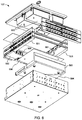
- FIG. 5 shows an upper exploded view of the drawer of FIG. 3 , in accordance with embodiments of the invention.
- FIG. 6 shows a lower exploded view of the drawer of FIG. 3 , in accordance with embodiments of the invention.
- FIG. 7 shows an underside oblique view of the drawer of FIG. 3 , with its bottom cover removed.
- FIG. 8 shows an upper rear oblique view of the drawer of FIG. 3 , in accordance with embodiments of the invention.
- FIG. 9 illustrates a partial view of the cabinet of FIG. 1 , with an insulation panel in place according to embodiments of the invention.
- FIG. 10 illustrates another embodiment of the cabinet of FIG. 1 with an insulation panel in place according to embodiments of the invention.
- FIG. 11 shows an upper oblique view of the top of the drawer of FIG. 3 with many components removed, to reveal a mechanism for achieving computer control of access to the individual storage bins within the drawer, in accordance with embodiments of the invention.
- FIG. 12 shows a portion of FIG. 11 in more detail.
- FIG. 13 shows a lid of a compartment of the drawer of FIG. 3 in an open position, in accordance with embodiments of the invention.
- FIG. 14 shows an upper rear oblique view of the drawer of FIG. 3 , with several components removed, in accordance with embodiments of the invention.
- FIG. 15 shows an enlarged view of a portion of FIG. 14 .
- FIG. 16 illustrates the installation of an insulation panel in the drawer of FIG. 3 , in accordance with embodiments of the invention.
- FIG. 17 illustrates an override mechanism in accordance with embodiments of the invention.
- FIG. 18 shows a portion of FIG. 17 in more detail.
- FIG. 1 illustrates a dispensing cabinet 100 in accordance with embodiments of the invention.
- Cabinet 100 includes a plurality of compartments, including drawers 101 a , 101 b , and 107 , and compartments accessible through doors 102 a and 102 b .
- Dispensing cabinet 100 also includes a computerized controller 103 , and one or more data entry devices such as keyboard 104 and keypad 105 .
- a display 106 enables communication of information to a user of dispensing cabinet 100 .
- drawer 107 includes a refrigeration system as discussed in more detail below.
- a dispensing cabinet may include other devices as well.
- dispensing cabinet 100 may hold medications or medical supplies, and may facilitate the accurate dispensing and tracking of medications or other medical supplies.
- Computerized controller 103 may include a processor, memory, input/output interfaces, and other components. Controller 103 may communicate remotely with other computerized systems, such as medical records systems, inventory and accounting systems, and the like.
- the various storage compartments such as drawers 101 a , 101 b and 107 may be under the control of controller 103 .
- each of drawers 101 a , 101 b and 107 may include an electronically-controllable locking mechanism, and may only be openable under the control of controller 103 .
- controller 103 may store information about what supplies are stored in which compartments of medication storage cabinet 100 .
- a health care worker may enter, using keyboard 104 or another input device, an identification of a patient who is under the care of the health care worker, and who will need medication during the worker's current rounds.
- Controller 103 may access the patient's medical file and determine what medications have been prescribed for that patient.
- Controller 103 may then permit access only to the drawer or drawers containing the prescribed medications for the patient.
- a particular compartment such as a bin within the correct drawer may also be highlighted, for example with a lighted indicator, to draw the health care worker to the correct medication.
- the health care worker can then remove the patient's prescribed medication.
- the level of control exercised by controller 103 may help in preventing medication and dosing errors, by reducing the likelihood that a health care worker will remove an incorrect medication from medication dispensing cabinet 100 .
- controller 103 may document and record which medication was dispensed, and may forward that information via a wired or wireless electronic network to inventory and accounting systems.
- the health care worker may enter his or her identification as well, and controller 103 may provide access only to those medications and supplies for which the worker is authorized to access.
- While medication dispensing cabinet 100 is shown as a stationary device, the invention is not so limited. Cabinets according to other embodiments may be portable, for example to facilitate transporting medications and supplies from a central supply store to a particular ward or department of a facility. It will be recognized that the particular arrangement of drawers, doors, or other features of a cabinet according to embodiments of the invention may be varied. For example, some cabinets or dispensing carts embodying the invention may use only drawers.
- compartments may be used, depending on the sizes of materials to be dispensed, and the level of security required for them.
- a cabinet embodying the invention may include guides or mounting features spaced a standardized distance apart, and different drawers may span different multiples of the spacing distance.
- a drawer spanning only the spacing distance may be called a “single” height drawer.
- a drawer spanning two of the spacing distance may be called a “double” height drawer.
- Triple height and taller drawers are also possible.
- a cabinet such as cabinet 100 may be configured with combinations of drawer heights, depending on the sizes of the items to be stored. In the example of FIG. 1 , drawer 101 b is a single height drawer, while drawer 107 is a triple height drawer.
- FIG. 2 illustrates a portable dispensing device 200 in which the invention may be embodied.
- portable dispensing device 200 can perform functions similar to those described above with respect to dispensing cabinet 100 .
- Dispensing device 200 includes wheels 201 to enable a health care worker to wheel the device from room to room.
- Dispensing device 200 may include one or more batteries, to power a computerized controller that performs tasks similar to controller 103 discussed above, and to provide power for other functions of dispensing device 200 .
- dispensing device 200 can preferably be connected to mains power when convenient, for charging the batteries and for powering the device without drawing on the battery when the device will be at a particular location for a period of time.
- Dispensing device 200 also includes a number of drawers 203 of varying heights. Each drawer 203 may include a visual indicator 204 for guiding a user to a particular drawer 203 , as is explained in more detail below. One or more of drawers 203 may include a refrigeration system in accordance with embodiments of the invention. Other drawers within cabinet 100 may not be refrigerated.
- FIG. 3 illustrates a front upper oblique view of drawer 107 in more detail, in accordance with embodiments of the invention.
- Drawer 107 has a front side 301 , a back side 302 , and right and left sides 303 and 304 , as viewed from front side 301 .
- Front side 301 is the side that would show at the front of a cabinet once drawer 107 is installed in the cabinet, and is the side from which a user would access drawer 107 .
- Drawer 107 may include guides 305 for mounting drawer 107 into a cabinet such as cabinet 100 , and enabling drawer to slide open (in the direction of front side 301 ) and closed (with drawer 107 substantially entirely within the cabinet).
- One or more fascia pieces 306 provide a decorative look to the front of drawer 107 , may provide an undercut handle for the user to grip in opening drawer 107 , and may include other features as described in more detail below.
- Front portion 307 of drawer 107 includes a number of compartments, which in FIG. 3 are covered by lids 308 .
- Rear portion 309 houses parts of a refrigeration system, described in more detail below.
- FIG. 4 shows a rear upper oblique view of drawer 107 .
- a mechanical latch 401 may be provided, which may interact with cabinet 100 .
- controller 103 may control latch so that drawer 107 can be opened only if a worker requesting access to drawer 107 has provided proper credentials.
- Lids 308 may be similarly controllable, so that only the storage location holding the required medicine or supplies is openable by the worker.
- Various electrical connectors 402 may be provided, to which cables (not shown) may be attached, so that drawer 107 can receive electrical power from cabinet 100 and may communicate with controller 103 .
- FIGS. 5 and 6 show upper and lower exploded views of drawer 107 , in accordance with embodiments of the invention.
- the interior of drawer 107 is essentially surrounded by insulation, including side insulation panels 501 , back insulation panel 502 , front insulation panel 503 , and bottom insulation panel 504 .
- Insulation panels 501 - 504 may be made of any suitable insulating material, for example a moldable foam insulation such as polyisocyanurate, polystyrene, polyurethane, or another kind of insulation. While four different insulation panels are shown, the insulation may be formed by more or fewer different segments.
- front insulation panel 503 may be molded monolithically with bottom insulation panel 504 . Other combinations are possible as well. (Insulation of the top of drawer 107 will be discussed below.)
- Compartments 505 reside in the chamber formed by insulation panels 501 - 504 .
- Compartments 505 may be defined by a divider made of any suitable material and formed by any suitable process, but may conveniently molded from a polymer such as polycarbonate, ABS, another polymer, or a blend of polymers.
- compartments 505 may be made from a metal such as stainless steel, aluminum, or another suitable metal.
- Compartments 505 may be integrally formed from a single piece of material, or may be separate from each other and placed into drawer 107 in a workable combination. Compartments 505 are covered by lids 308 .
- Evaporator 506 is disposed between compartments 505 and bottom insulation panel 504 .
- Evaporator 506 is part of a refrigeration system integrated into drawer 107 .
- Evaporator 506 may be, for example, a roll-bonded evaporator, formed by roll bonding two sheets of metal with a pattern of channels marked on them, and then inflating the channels to form a network or serpentine passage through the channels for the flow of refrigerant.
- Evaporator 506 absorbs thermal energy from the interior of drawer 107 by virtue of its low temperature, and carries it outside the interior of drawer 107 , cooling the interior of drawer 107 , including compartments 505 .
- the refrigeration system preferably uses a refrigerant that does not contain chlorinated fluorocarbons (CFCs).
- CFCs chlorinated fluorocarbons
- a fan 509 draws air through condenser 508 to cool the refrigerant after the refrigerant has been heated in evaporator 506 and compressed in compressor 507 , to expel thermal energy outside of cabinet 100 .
- a glycol bottle 510 may be provided, and may fit in a special compartment 511 in the interior of drawer 107 , with its own lid 512 .
- a temperature sensor is submerged in glycol within bottle 510 , and connected to controller 103 so that controller 103 can monitor the temperature of the interior of drawer 107 .
- the glycol serves to buffer the sensor from rapid fluctuations in apparent temperature that may be caused by, for example, openings of drawer 107 from cabinet 100 .
- controller 103 may signal the refrigeration system to cycle on and off based on the temperature as sensed by the temperature sensor.
- FIG. 7 shows an underside oblique view of drawer 107 , with its bottom cover removed, exposing bottom insulation panel 504 .
- bottom insulation panel 504 has a funnel-shaped air flow path 701 molded into it.
- a bottom panel (not shown) forms the remaining side of air flow path 701 .
- Air may enter air flow path 701 through an opening in the front side of drawer 107 , for example an opening hidden in one of fascia pieces 306 .
- the funnel shape of air flow path 701 directs the air to condenser 508 under the impetus of fan 509 (not visible in FIG. 7 ). After flowing through condenser 508 , the air is exhausted to the environment at the back of cabinet 100 .
- This air flow arrangement serves multiple purposes. First, it provides cooling air to condenser 508 , for cooling the refrigerant in the refrigeration system as part of the refrigeration cycle. The air is exhausted from the back of cabinet 100 rather than the front, which may be preferable for user comfort. And second, the air flow under insulation panel 504 can evaporate and exhaust any condensation that my form under insulation panel 504 . Standoffs 702 may hold the back cover away from insulation panel 504 , permitting at least a small amount of air 703 to flow over substantially the entire underside of insulation panel 504 .
- FIG. 8 shows an upper rear oblique view of drawer 107 , in accordance with embodiments of the invention.
- the view of FIG. 8 is similar to the view of FIG. 4 , with the addition of a top insulation panel 801 .
- Top insulation panel 801 may be shaped and sized to slide into an open recess left in the top of drawer 107 by the other components.
- top insulation panel 801 may fit between the tops of side insulation panels 501 and may contact front insulation panel 503 when top insulation panel 801 if fully installed on drawer 107 .
- Top insulation panel 801 may also contact back insulation panel 502 (not visible in FIG. 8 ) so that the interior of drawer 107 is essentially encased in insulation.
- Top insulation panel 108 is preferably mounted in cabinet 100 such that top insulation panel 801 remains inside cabinet 100 when drawer 107 is opened, so as not to interfere with access to the compartments in drawer 107 . When drawer 107 is closed, top insulation panel 801 automatically covers drawer 107 again.
- top insulation panel 801 may travel with drawer 107 when drawer 107 is opened, and the user may simply slide top insulation panel 801 back toward cabinet 100 to gain access to the interior of drawer 107 .
- Top insulation panel 801 may be made of any suitable material, for example a material similar to the material of the other insulation panels, or a different material.
- FIG. 9 illustrates a partial view of cabinet 100 with insulation panel 801 in place above drawer 107 .
- Drawers immediately above drawer 107 have been removed.
- insulation panel 801 remains in place, so that the interior of drawer 107 is accessible when drawer 107 is open, but drawer 107 is fully insulated when closed.
- a bracket 901 holds insulation panel 801 in place within cabinet 100 , and drawer 107 slides beneath insulation panel 801 .
- other arrangements are possible.
- FIG. 10 illustrates another embodiment, in which insulation panel 801 is slidingly captured within a groove 1001 in the side of drawer 107 .
- Insulation panel 801 may be attached to a back wall of cabinet 100 so that insulation panel 801 does not slide out of cabinet 100 when drawer 107 is opened. In other embodiments, insulation panel 801 may simply be pushed back by the user to expose the interior of drawer 107 when drawer 107 is open.
- FIG. 11 shows an upper oblique view of the top of drawer 107 with many components removed, to reveal a mechanism for achieving computer control of access to the individual storage bins in drawer 107 .
- FIG. 12 shows a portion of FIG. 11 in more detail.
- lid 1101 includes a lever 1102 configured to rotate with lid 1101 about an axis 1103 .
- a blade 1104 connected to an armature of a solenoid 1105 blocks rotation of lever 1102 , and therefore of lid 1101 . In this condition, the bin under lid 1101 is locked.
- FIG. 13 shows lid 1101 in the open position.
- the user may lift lid 1101 using finger pull 1301 once solenoid 1105 has released the lid.
- the user can simply push lid 1101 back to the closed position.
- Lever 1102 interacts with the angled top of blade 1104 to deflect blade 1104 downward to allow lever 1102 to pass.
- blade 1104 can return to its normal upward position under the action of a spring (not visible in FIG. 13 ), locking lid 1101 in the closed position.
- Solenoids 1105 are but one example of a type of actuator that may be used to control access to the compartments in drawer 107 , and other kinds of actuators may be used. For example, magnetic actuators, motors with appropriate linkages, or other kinds of actuators.
- FIG. 14 shows an upper rear oblique view of drawer 107 , with several components removed, and FIG. 15 shows an enlarged view of a portion of FIG. 14 .
- a printed circuit board 1401 is mounted to side 1402 of drawer 107 .
- a number of solenoids 1105 are mounted to circuit board 1401 , and are connected via connectors 1501 to other circuitry (not shown) and eventually to controller 103 .
- Similar components may be attached to the inner face of the other side 1403 of drawer 107 as well, but are not visible in FIG. 14 .
- a number of sensors 1502 may be provided, for providing positive feedback when the lever 1102 of one of lids 308 is in the closed position.
- Light emitting diodes (LEDs) 1503 may be present and also controllable by controller 103 , for visually indicating the status of particular compartments through light pipes 1504 , which extend to the top of drawer 107 .
- side insulation panel 501 includes a number of recesses 1601 for accommodating printed circuit board 1401 and the components on it, including solenoids 1105 .
- side insulation panel 501 is in place in drawer 107 , printed circuit board 1401 and its associated components are positioned outside the refrigerated interior of drawer 107 .
- Various slots 1602 in insulation panel 501 provide access to components on circuit board 1401 , and are as small as possible so as to not compromise the insulating effect of insulation panel 501 more than necessary.
- a manual override mechanism for unlocking the compartments in drawer 107 manually, without reliance on controller 103 .
- This capability may be useful, for example during a power outage or other occasion when controller 103 is not able to open the compartments.
- FIGS. 17 and 18 illustrate one example override mechanism.
- An override plate 1701 fits under the insulation (not shown) at the bottom of drawer 107 , and includes risers 1702 at the sides of drawer 107 corresponding to solenoids 1105 . Risers 1702 may extend inside the temperature-controlled interior of drawer 107 , passing though slits in the lower insulation panel.
- Override plate 1701 may be accessible from the bottom of drawer 107 . For example, a user may insert a finger through hole 1703 in bottom plate 1704 of drawer 107 , to actuate override plate 1701 against a spring 1705 .
- a ramp feature 1801 in each riser 1702 interacts with a pin 1802 on the armature 1803 of the corresponding solenoid 1105 , drawing armature 1803 and blade 1104 downward. With blade 1104 withdrawn, the corresponding lid is unlocked, as is described above and shown in FIG. 13 .
Abstract
Description
Claims (19)
Priority Applications (11)
| Application Number | Priority Date | Filing Date | Title |
|---|---|---|---|
| US15/816,775 US10663218B2 (en) | 2017-11-17 | 2017-11-17 | Dispensing system with temperature controlled drawers |
| KR1020207016722A KR102592222B1 (en) | 2017-11-17 | 2018-11-16 | Temperature controlled dispensing drawer |
| JP2020523708A JP7301825B6 (en) | 2017-11-17 | 2018-11-16 | temperature controlled distribution drawer |
| EP18878839.2A EP3710764A4 (en) | 2017-11-17 | 2018-11-16 | Temperature controlled dispense drawer |
| PCT/US2018/061426 WO2019099767A1 (en) | 2017-11-17 | 2018-11-16 | Temperature controlled dispense drawer |
| BR112020008858-7A BR112020008858A2 (en) | 2017-11-17 | 2018-11-16 | temperature controlled dispensing drawer |
| AU2018368950A AU2018368950A1 (en) | 2017-11-17 | 2018-11-16 | Temperature controlled dispense drawer |
| CN201880074315.7A CN111356888B (en) | 2017-11-17 | 2018-11-16 | Temperature controlled dispensing drawer |
| CA3079749A CA3079749A1 (en) | 2017-11-17 | 2018-11-16 | Temperature controlled dispense drawer |
| US16/856,469 US11732955B2 (en) | 2017-11-17 | 2020-04-23 | Dispensing system with temperature controlled drawers |
| US18/330,992 US20230314068A1 (en) | 2017-11-17 | 2023-06-07 | Dispensing system with temperature controlled drawers |
Applications Claiming Priority (1)
| Application Number | Priority Date | Filing Date | Title |
|---|---|---|---|
| US15/816,775 US10663218B2 (en) | 2017-11-17 | 2017-11-17 | Dispensing system with temperature controlled drawers |
Related Child Applications (1)
| Application Number | Title | Priority Date | Filing Date |
|---|---|---|---|
| US16/856,469 Division US11732955B2 (en) | 2017-11-17 | 2020-04-23 | Dispensing system with temperature controlled drawers |
Publications (2)
| Publication Number | Publication Date |
|---|---|
| US20190154329A1 US20190154329A1 (en) | 2019-05-23 |
| US10663218B2 true US10663218B2 (en) | 2020-05-26 |
Family
ID=66532868
Family Applications (3)
| Application Number | Title | Priority Date | Filing Date |
|---|---|---|---|
| US15/816,775 Active 2038-04-12 US10663218B2 (en) | 2017-11-17 | 2017-11-17 | Dispensing system with temperature controlled drawers |
| US16/856,469 Active 2038-08-31 US11732955B2 (en) | 2017-11-17 | 2020-04-23 | Dispensing system with temperature controlled drawers |
| US18/330,992 Pending US20230314068A1 (en) | 2017-11-17 | 2023-06-07 | Dispensing system with temperature controlled drawers |
Family Applications After (2)
| Application Number | Title | Priority Date | Filing Date |
|---|---|---|---|
| US16/856,469 Active 2038-08-31 US11732955B2 (en) | 2017-11-17 | 2020-04-23 | Dispensing system with temperature controlled drawers |
| US18/330,992 Pending US20230314068A1 (en) | 2017-11-17 | 2023-06-07 | Dispensing system with temperature controlled drawers |
Country Status (1)
| Country | Link |
|---|---|
| US (3) | US10663218B2 (en) |
Cited By (3)
| Publication number | Priority date | Publication date | Assignee | Title |
|---|---|---|---|---|
| US11392101B2 (en) * | 2018-06-01 | 2022-07-19 | Carefusion 303, Inc. | Secure refrigerated bin systems |
| US11536506B2 (en) | 2018-09-12 | 2022-12-27 | Omnicell, Inc. | Temperature controlled dispense drawer |
| US11732955B2 (en) | 2017-11-17 | 2023-08-22 | Omnicell, Inc. | Dispensing system with temperature controlled drawers |
Families Citing this family (1)
| Publication number | Priority date | Publication date | Assignee | Title |
|---|---|---|---|---|
| CN112245179B (en) * | 2020-10-20 | 2021-09-21 | 马鞍山聚力科技有限公司 | Medical delivery robot preventing toppling |
Citations (47)
| Publication number | Priority date | Publication date | Assignee | Title |
|---|---|---|---|---|
| JPS60102482A (en) | 1983-11-04 | 1985-06-06 | 松下電器産業株式会社 | Lid lock mechanism |
| US5190185A (en) | 1990-05-18 | 1993-03-02 | Baxter International Inc. | Medication transport and dispensing magazine |
| US5377864A (en) | 1989-05-25 | 1995-01-03 | Baxter International Inc. | Drug dispensing apparatus |
| US5745366A (en) | 1994-07-14 | 1998-04-28 | Omnicell Technologies, Inc. | Pharmaceutical dispensing device and methods |
| US5805455A (en) | 1993-07-21 | 1998-09-08 | Omincell Technologies, Inc. | Methods for dispensing items |
| US5805456A (en) | 1994-07-14 | 1998-09-08 | Omnicell Technologies, Inc. | Device and method for providing access to items to be dispensed |
| JPH10248658A (en) | 1997-03-08 | 1998-09-22 | Dmt Gmbh Feinwerktechnische Komplettloesungen | Mechanical casing |
| US5905653A (en) | 1994-07-14 | 1999-05-18 | Omnicell Technologies, Inc. | Methods and devices for dispensing pharmaceutical and medical supply items |
| US5927540A (en) | 1997-08-20 | 1999-07-27 | Omnicell Technologies, Inc. | Controlled dispensing system and method |
| US6011999A (en) | 1997-12-05 | 2000-01-04 | Omnicell Technologies, Inc. | Apparatus for controlled dispensing of pharmaceutical and medical supplies |
| US6039467A (en) | 1996-12-05 | 2000-03-21 | Omnicell Technologies, Inc. | Lighting system and methods for a dispensing device |
| US6112547A (en) | 1998-07-10 | 2000-09-05 | Spauschus Associates, Inc. | Reduced pressure carbon dioxide-based refrigeration system |
| US6151536A (en) | 1998-09-28 | 2000-11-21 | Omnicell.Com | Dispensing system and methods |
| US6170929B1 (en) | 1998-12-02 | 2001-01-09 | Ronald H. Wilson | Automated medication-dispensing cart |
| CN1301337A (en) | 1998-04-24 | 2001-06-27 | 让·皮埃尔·吉雄 | Refrigerating drawer for storage column |
| US6272394B1 (en) | 1993-07-21 | 2001-08-07 | Omnicell.Com | Methods and apparatus for dispensing items |
| US20020121095A1 (en) | 2000-09-08 | 2002-09-05 | Adamski Joseph R. | Controlled temperature compartment apparatus |
| US6640159B2 (en) | 1996-12-05 | 2003-10-28 | Omnicell Technologies, Inc. | Replacement liner and methods for a dispensing device |
| US6760643B2 (en) | 1994-10-11 | 2004-07-06 | Omnicell, Inc. | Methods and apparatus for dispensing items |
| US6975922B2 (en) | 2003-05-08 | 2005-12-13 | Omnicell, Inc. | Secured dispensing cabinet and methods |
| US20060016202A1 (en) | 2004-07-23 | 2006-01-26 | Daniel Lyvers | Refrigerator with system for controlling drawer temperatures |
| US20070199262A1 (en) * | 2004-06-03 | 2007-08-30 | Hill-Rom Services, Inc. | Patient Care Modules For Hospital Walls |
| US20070228899A1 (en) * | 2005-09-08 | 2007-10-04 | Iscar Ltd. | Dispensing System for Tools |
| US7348884B2 (en) | 2004-07-29 | 2008-03-25 | Omnicell, Inc. | RFID cabinet |
| US20080148765A1 (en) | 2005-04-07 | 2008-06-26 | Whirlpool Corporation | Refrigerated Drawer Structure |
| US20080264962A1 (en) * | 2007-02-23 | 2008-10-30 | Cerner Innovation, Inc. | Medication dispensing apparatus |
| US20090302178A1 (en) * | 2008-06-05 | 2009-12-10 | Drager Medical Ag & Co. Kg | Fastening device, medical instrument and instrument system with such a fastening device |
| US20100300130A1 (en) * | 2006-03-29 | 2010-12-02 | S&S X-Ray Products, Inc. | Medical Storage Case with Remote Unlocking Refrigerator with thermal Spoilage Protection |
| US8126590B2 (en) | 2007-06-19 | 2012-02-28 | Omnicell, Inc. | Patient-specific bin systems, methods, and devices |
| US20120137706A1 (en) * | 2009-12-07 | 2012-06-07 | Meps Real-Time, Inc. | Rfid enabled drawer refrigeration system |
| WO2012075449A2 (en) | 2010-12-03 | 2012-06-07 | Meps Real-Time, Inc. | Rfid enabled drawer refrigeration system |
| US8196939B2 (en) | 2008-02-21 | 2012-06-12 | Rubbermaid Incorporated | Medical cart and drawer assembly and lock |
| CN102582950A (en) | 2012-03-05 | 2012-07-18 | 北京华兴长泰物联网技术研究院有限责任公司 | Box cover locking device |
| US20120203377A1 (en) | 2006-08-21 | 2012-08-09 | Omnicell, Inc. | Medication dispensing cart |
| US8280550B2 (en) | 2008-06-17 | 2012-10-02 | Omnicell, Inc. | Cabinet with remote integration |
| US20120330462A1 (en) * | 2011-06-22 | 2012-12-27 | Ralf Maroney | Computer-Controlled Common Access Cabinet |
| EP2551618A2 (en) | 2011-07-26 | 2013-01-30 | Vestel Beyaz Esya Sanayi Ve Ticaret A.S. | A cooling device |
| US20130123974A1 (en) * | 2011-11-11 | 2013-05-16 | Talyst Inc. | Combined pharmaceutical packager and prepackaged pharmaceutical system |
| CN203133951U (en) | 2013-01-17 | 2013-08-14 | 汪岩 | Integrated management computer equipment for hospital electronic medical records |
| US8991194B2 (en) | 2012-05-07 | 2015-03-31 | Phononic Devices, Inc. | Parallel thermoelectric heat exchange systems |
| US9013309B2 (en) * | 2009-12-07 | 2015-04-21 | Meps Real-Time, Inc. | System and method for tracking medical items and identifying item characteristics |
| US20150233648A1 (en) | 2012-08-01 | 2015-08-20 | Goseling Ug | Cold Reservoir Device and Cooling System Arrangement |
| US9242732B2 (en) | 2010-10-25 | 2016-01-26 | Icebridge Oy | Cooling solution in a trolley of an aeroplane |
| US20160054047A1 (en) | 2014-08-21 | 2016-02-25 | Samsung Electronics Co., Ltd. | Refrigerator |
| US20160379022A1 (en) * | 2015-06-27 | 2016-12-29 | Meps Real-Time, Inc. | Medication tracking system and method using hybrid isolated magnetic dipole probe |
| US9595241B2 (en) | 2015-01-06 | 2017-03-14 | Imicrodata Corporation | Addressable drawer organizer with item display panel |
| US10362866B2 (en) * | 2015-03-16 | 2019-07-30 | Cubex Llc | Methods for controlled dispensing |
Family Cites Families (44)
| Publication number | Priority date | Publication date | Assignee | Title |
|---|---|---|---|---|
| US3364694A (en) * | 1966-12-02 | 1968-01-23 | Whirlpool Co | Refrigerator apparatus |
| JPS4976923U (en) | 1972-09-28 | 1974-07-03 | ||
| JPS526563A (en) | 1975-07-04 | 1977-01-19 | Toshiba Corp | Electronic clock with luminous bodies |
| JPS5839349Y2 (en) | 1979-04-06 | 1983-09-05 | 株式会社東芝 | refrigerator |
| DK331388A (en) | 1987-07-09 | 1989-01-10 | Hoffmann La Roche | ANTIOXIDANTS |
| JPH0526563A (en) | 1991-07-23 | 1993-02-02 | Toshiba Corp | Refrigerator |
| US5501076A (en) | 1993-04-14 | 1996-03-26 | Marlow Industries, Inc. | Compact thermoelectric refrigerator and module |
| JPH06304230A (en) | 1993-04-22 | 1994-11-01 | Sanyo Electric Co Ltd | Medicine administrating cabinet |
| US5661978A (en) * | 1994-12-09 | 1997-09-02 | Pyxis Corporation | Medical dispensing drawer and thermoelectric device for cooling the contents therein |
| KR200170050Y1 (en) | 1995-12-28 | 2000-03-02 | 전주범 | Evaporator of refrigerator |
| US6612116B2 (en) * | 1999-02-26 | 2003-09-02 | Maytag Corporation | Thermoelectric temperature controlled refrigerator food storage compartment |
| CH693965A5 (en) * | 1999-08-20 | 2004-05-14 | Forster Ag Hermann | Kuehlgeraet. |
| JP2001091173A (en) | 1999-09-24 | 2001-04-06 | Sanyo Electric Co Ltd | Heat conveying apparatus |
| US6530231B1 (en) | 2000-09-22 | 2003-03-11 | Te Technology, Inc. | Thermoelectric assembly sealing member and thermoelectric assembly incorporating same |
| JP2002195721A (en) | 2000-12-28 | 2002-07-10 | Gac Corp | Refrigerator |
| US6715299B2 (en) | 2001-10-19 | 2004-04-06 | Samsung Electronics Co., Ltd. | Refrigerator for cosmetics and method of controlling the same |
| US7052097B2 (en) * | 2002-12-06 | 2006-05-30 | Mckesson Automation, Inc. | High capacity drawer with mechanical indicator for a dispensing device |
| KR100557099B1 (en) | 2003-12-09 | 2006-03-03 | 엘지전자 주식회사 | Radiating apparatus of built-in refrigerator |
| EP1586253B1 (en) | 2004-04-13 | 2010-05-26 | Whirlpool Corporation | Drawer appliance |
| US7706915B2 (en) | 2004-12-03 | 2010-04-27 | Saudi Arabian Oil Company | System and software of enhanced pharmacy services and related methods |
| US7693603B2 (en) * | 2007-01-22 | 2010-04-06 | John David Higham | Pharmaceutical dispensing system with coordinate guidance |
| JP4976923B2 (en) | 2007-05-30 | 2012-07-18 | 株式会社クボタ | Work vehicle |
| JP4538029B2 (en) | 2007-08-24 | 2010-09-08 | 株式会社東芝 | refrigerator |
| JP5342157B2 (en) | 2007-12-07 | 2013-11-13 | パナソニック株式会社 | refrigerator |
| DE102007048575A1 (en) | 2007-10-10 | 2009-04-16 | BSH Bosch und Siemens Hausgeräte GmbH | The refrigerator |
| GB2461070A (en) * | 2008-06-19 | 2009-12-23 | Shafir Production Systems Ltd | Cabinet for handling distributable items comprising drawer access and control system and lockable bins |
| US8744620B2 (en) | 2008-10-31 | 2014-06-03 | Medminder Systems, Inc. | Interactive medication dispensing system with locking compartments |
| KR101544452B1 (en) * | 2008-12-11 | 2015-08-13 | 엘지전자 주식회사 | Refrigerator with heat conduction sheet |
| US8997517B2 (en) * | 2009-02-27 | 2015-04-07 | Electrolux Home Products, Inc. | Controlled temperature compartment for refrigerator |
| KR101193881B1 (en) | 2010-05-28 | 2012-10-26 | 현대제철 주식회사 | Apparatus for measuring temperature of material |
| US8457784B2 (en) * | 2011-01-24 | 2013-06-04 | Carefusion 303, Inc. | Memory wire terminator with spring contacts |
| KR101829222B1 (en) | 2011-02-15 | 2018-02-19 | 엘지전자 주식회사 | Refrigerator |
| JP5839349B2 (en) | 2011-04-20 | 2016-01-06 | 共立製薬株式会社 | Liquid mixing mechanism |
| US9109819B2 (en) | 2011-05-31 | 2015-08-18 | Lg Electronics Inc. | Refrigerator |
| US9078520B2 (en) * | 2011-11-08 | 2015-07-14 | S&S X-Ray, Products Inc | Locking bin drawer with slide-out trays for medications cabinet |
| US9978139B2 (en) | 2013-08-26 | 2018-05-22 | Equashield Medical Ltd. | Method and apparatus for monitoring, documenting and assisting with the manual compounding of medications |
| AU2015315334B2 (en) | 2014-09-08 | 2018-04-05 | Becton, Dickinson And Company | System and method for preparing a pharmaceutical compound |
| WO2016181223A2 (en) * | 2015-05-13 | 2016-11-17 | 3Rd Stone Design Inc. | Portable refrigerator and method of using |
| US10045899B2 (en) * | 2016-07-06 | 2018-08-14 | Capsa Solutions Llc | Modular and fully traceable delivery system |
| US10604967B2 (en) * | 2016-07-06 | 2020-03-31 | Capsa Solutions Llc | Bin having electronic low profile locking assembly |
| KR102279484B1 (en) * | 2017-03-13 | 2021-07-20 | 엘지전자 주식회사 | Refrigerator |
| CN110213990B (en) | 2017-03-16 | 2022-04-26 | 株式会社村田制作所 | Fluid control device and sphygmomanometer |
| US10663218B2 (en) | 2017-11-17 | 2020-05-26 | Omnicell, Inc. | Dispensing system with temperature controlled drawers |
| CA3082168C (en) | 2017-11-30 | 2023-02-21 | Omnicell, Inc. | Compounding device system |
-
2017
- 2017-11-17 US US15/816,775 patent/US10663218B2/en active Active
-
2020
- 2020-04-23 US US16/856,469 patent/US11732955B2/en active Active
-
2023
- 2023-06-07 US US18/330,992 patent/US20230314068A1/en active Pending
Patent Citations (52)
| Publication number | Priority date | Publication date | Assignee | Title |
|---|---|---|---|---|
| JPS60102482A (en) | 1983-11-04 | 1985-06-06 | 松下電器産業株式会社 | Lid lock mechanism |
| US5377864A (en) | 1989-05-25 | 1995-01-03 | Baxter International Inc. | Drug dispensing apparatus |
| US5190185A (en) | 1990-05-18 | 1993-03-02 | Baxter International Inc. | Medication transport and dispensing magazine |
| US5805455A (en) | 1993-07-21 | 1998-09-08 | Omincell Technologies, Inc. | Methods for dispensing items |
| US6272394B1 (en) | 1993-07-21 | 2001-08-07 | Omnicell.Com | Methods and apparatus for dispensing items |
| US6609047B1 (en) | 1993-07-21 | 2003-08-19 | Omnicell Technologies, Inc. | Methods and apparatus for dispensing items |
| US6385505B1 (en) | 1993-07-21 | 2002-05-07 | Omnicell.Com | Methods and apparatus for dispensing items |
| US5745366A (en) | 1994-07-14 | 1998-04-28 | Omnicell Technologies, Inc. | Pharmaceutical dispensing device and methods |
| US5805456A (en) | 1994-07-14 | 1998-09-08 | Omnicell Technologies, Inc. | Device and method for providing access to items to be dispensed |
| US5905653A (en) | 1994-07-14 | 1999-05-18 | Omnicell Technologies, Inc. | Methods and devices for dispensing pharmaceutical and medical supply items |
| US6760643B2 (en) | 1994-10-11 | 2004-07-06 | Omnicell, Inc. | Methods and apparatus for dispensing items |
| US6039467A (en) | 1996-12-05 | 2000-03-21 | Omnicell Technologies, Inc. | Lighting system and methods for a dispensing device |
| US6640159B2 (en) | 1996-12-05 | 2003-10-28 | Omnicell Technologies, Inc. | Replacement liner and methods for a dispensing device |
| JPH10248658A (en) | 1997-03-08 | 1998-09-22 | Dmt Gmbh Feinwerktechnische Komplettloesungen | Mechanical casing |
| US5927540A (en) | 1997-08-20 | 1999-07-27 | Omnicell Technologies, Inc. | Controlled dispensing system and method |
| US6011999A (en) | 1997-12-05 | 2000-01-04 | Omnicell Technologies, Inc. | Apparatus for controlled dispensing of pharmaceutical and medical supplies |
| CN1301337A (en) | 1998-04-24 | 2001-06-27 | 让·皮埃尔·吉雄 | Refrigerating drawer for storage column |
| US6112547A (en) | 1998-07-10 | 2000-09-05 | Spauschus Associates, Inc. | Reduced pressure carbon dioxide-based refrigeration system |
| US6151536A (en) | 1998-09-28 | 2000-11-21 | Omnicell.Com | Dispensing system and methods |
| US6170929B1 (en) | 1998-12-02 | 2001-01-09 | Ronald H. Wilson | Automated medication-dispensing cart |
| US20020121095A1 (en) | 2000-09-08 | 2002-09-05 | Adamski Joseph R. | Controlled temperature compartment apparatus |
| US7571024B2 (en) | 2003-05-08 | 2009-08-04 | Omnicell, Inc. | Secured dispensing cabinet and methods |
| US6975922B2 (en) | 2003-05-08 | 2005-12-13 | Omnicell, Inc. | Secured dispensing cabinet and methods |
| US7835819B2 (en) | 2003-05-08 | 2010-11-16 | Omnicell, Inc. | Secured dispensing cabinet and methods |
| US20070199262A1 (en) * | 2004-06-03 | 2007-08-30 | Hill-Rom Services, Inc. | Patient Care Modules For Hospital Walls |
| US20060016202A1 (en) | 2004-07-23 | 2006-01-26 | Daniel Lyvers | Refrigerator with system for controlling drawer temperatures |
| US7348884B2 (en) | 2004-07-29 | 2008-03-25 | Omnicell, Inc. | RFID cabinet |
| US7675421B2 (en) | 2004-07-29 | 2010-03-09 | Omnicell, Inc. | RFID cabinet |
| US20080148765A1 (en) | 2005-04-07 | 2008-06-26 | Whirlpool Corporation | Refrigerated Drawer Structure |
| US20070228899A1 (en) * | 2005-09-08 | 2007-10-04 | Iscar Ltd. | Dispensing System for Tools |
| US20100300130A1 (en) * | 2006-03-29 | 2010-12-02 | S&S X-Ray Products, Inc. | Medical Storage Case with Remote Unlocking Refrigerator with thermal Spoilage Protection |
| US20120203377A1 (en) | 2006-08-21 | 2012-08-09 | Omnicell, Inc. | Medication dispensing cart |
| US20080264962A1 (en) * | 2007-02-23 | 2008-10-30 | Cerner Innovation, Inc. | Medication dispensing apparatus |
| US8126590B2 (en) | 2007-06-19 | 2012-02-28 | Omnicell, Inc. | Patient-specific bin systems, methods, and devices |
| US8196939B2 (en) | 2008-02-21 | 2012-06-12 | Rubbermaid Incorporated | Medical cart and drawer assembly and lock |
| US20090302178A1 (en) * | 2008-06-05 | 2009-12-10 | Drager Medical Ag & Co. Kg | Fastening device, medical instrument and instrument system with such a fastening device |
| US8280550B2 (en) | 2008-06-17 | 2012-10-02 | Omnicell, Inc. | Cabinet with remote integration |
| US20120137706A1 (en) * | 2009-12-07 | 2012-06-07 | Meps Real-Time, Inc. | Rfid enabled drawer refrigeration system |
| US9013309B2 (en) * | 2009-12-07 | 2015-04-21 | Meps Real-Time, Inc. | System and method for tracking medical items and identifying item characteristics |
| US9242732B2 (en) | 2010-10-25 | 2016-01-26 | Icebridge Oy | Cooling solution in a trolley of an aeroplane |
| WO2012075449A2 (en) | 2010-12-03 | 2012-06-07 | Meps Real-Time, Inc. | Rfid enabled drawer refrigeration system |
| US20120330462A1 (en) * | 2011-06-22 | 2012-12-27 | Ralf Maroney | Computer-Controlled Common Access Cabinet |
| EP2551618A2 (en) | 2011-07-26 | 2013-01-30 | Vestel Beyaz Esya Sanayi Ve Ticaret A.S. | A cooling device |
| US20130123974A1 (en) * | 2011-11-11 | 2013-05-16 | Talyst Inc. | Combined pharmaceutical packager and prepackaged pharmaceutical system |
| CN102582950A (en) | 2012-03-05 | 2012-07-18 | 北京华兴长泰物联网技术研究院有限责任公司 | Box cover locking device |
| US8991194B2 (en) | 2012-05-07 | 2015-03-31 | Phononic Devices, Inc. | Parallel thermoelectric heat exchange systems |
| US20150233648A1 (en) | 2012-08-01 | 2015-08-20 | Goseling Ug | Cold Reservoir Device and Cooling System Arrangement |
| CN203133951U (en) | 2013-01-17 | 2013-08-14 | 汪岩 | Integrated management computer equipment for hospital electronic medical records |
| US20160054047A1 (en) | 2014-08-21 | 2016-02-25 | Samsung Electronics Co., Ltd. | Refrigerator |
| US9595241B2 (en) | 2015-01-06 | 2017-03-14 | Imicrodata Corporation | Addressable drawer organizer with item display panel |
| US10362866B2 (en) * | 2015-03-16 | 2019-07-30 | Cubex Llc | Methods for controlled dispensing |
| US20160379022A1 (en) * | 2015-06-27 | 2016-12-29 | Meps Real-Time, Inc. | Medication tracking system and method using hybrid isolated magnetic dipole probe |
Non-Patent Citations (2)
| Title |
|---|
| "The Importance of Using Glycol-Encased Temperature Probes" accucold for Summit Appliance, Nov. 4, 2017, [online] <retrieved from URL: http://www.accucold.com/glycolbasedprobes> entire document. |
| PCT/US2018/061426 received an International Search Report and Written Opinion dated Mar. 27, 2019, 16 pages. |
Cited By (4)
| Publication number | Priority date | Publication date | Assignee | Title |
|---|---|---|---|---|
| US11732955B2 (en) | 2017-11-17 | 2023-08-22 | Omnicell, Inc. | Dispensing system with temperature controlled drawers |
| US11392101B2 (en) * | 2018-06-01 | 2022-07-19 | Carefusion 303, Inc. | Secure refrigerated bin systems |
| US11789420B2 (en) | 2018-06-01 | 2023-10-17 | Carefusion 303, Inc. | Secure refrigerated bin systems |
| US11536506B2 (en) | 2018-09-12 | 2022-12-27 | Omnicell, Inc. | Temperature controlled dispense drawer |
Also Published As
| Publication number | Publication date |
|---|---|
| US20190154329A1 (en) | 2019-05-23 |
| US20200248958A1 (en) | 2020-08-06 |
| US20230314068A1 (en) | 2023-10-05 |
| US11732955B2 (en) | 2023-08-22 |
Similar Documents
| Publication | Publication Date | Title |
|---|---|---|
| US11732955B2 (en) | Dispensing system with temperature controlled drawers | |
| JP7301825B2 (en) | temperature controlled distribution drawer | |
| US6788997B1 (en) | Medical cabinet with adjustable drawers | |
| US6895304B2 (en) | Method of operating a dispensing cabinet | |
| US7052097B2 (en) | High capacity drawer with mechanical indicator for a dispensing device | |
| US5905653A (en) | Methods and devices for dispensing pharmaceutical and medical supply items | |
| US20030201697A1 (en) | Storage device for health care facility | |
| FI95848C (en) | Microprocessor controlled system for arranging adjacent compartments | |
| US5805456A (en) | Device and method for providing access to items to be dispensed | |
| US20220011042A1 (en) | Controlled inventory refrigerated dispensing system | |
| US6112502A (en) | Restocking method for medical item dispensing system | |
| US8547203B2 (en) | Dynamic control containment unit | |
| US7142944B2 (en) | Apparatus for securing drawer contents | |
| JPH09503732A (en) | Method and device for dispensing articles | |
| US20030222548A1 (en) | Storage device for health care facility | |
| EP2363831A1 (en) | Stock monitoring | |
| WO2008024722A2 (en) | Solar charged mobile working stations | |
| EP0954800B1 (en) | Pharmaceutical dispensing device and methods | |
| US20230043496A1 (en) | Temperature controlled dispense drawer | |
| US20140145574A1 (en) | Endless Chain Frozen Vial Storage Module | |
| JPH0747106A (en) | Medicine managing storage box |
Legal Events
| Date | Code | Title | Description |
|---|---|---|---|
| FEPP | Fee payment procedure |
Free format text: ENTITY STATUS SET TO UNDISCOUNTED (ORIGINAL EVENT CODE: BIG.); ENTITY STATUS OF PATENT OWNER: LARGE ENTITY |
|
| AS | Assignment |
Owner name: OMNICELL, INC., CALIFORNIA Free format text: ASSIGNMENT OF ASSIGNORS INTEREST;ASSIGNOR:BELLIGUNDU, SUNIL;REEL/FRAME:045110/0073 Effective date: 20171214 |
|
| STPP | Information on status: patent application and granting procedure in general |
Free format text: DOCKETED NEW CASE - READY FOR EXAMINATION |
|
| STPP | Information on status: patent application and granting procedure in general |
Free format text: NON FINAL ACTION MAILED |
|
| STPP | Information on status: patent application and granting procedure in general |
Free format text: RESPONSE TO NON-FINAL OFFICE ACTION ENTERED AND FORWARDED TO EXAMINER |
|
| STPP | Information on status: patent application and granting procedure in general |
Free format text: NON FINAL ACTION MAILED |
|
| AS | Assignment |
Owner name: WELLS FARGO BANK, NATIONAL ASSOCIATION, AS ADMINIS Free format text: GRANT OF PATENT SECURITY INTEREST;ASSIGNOR:OMNICELL, INC.;REEL/FRAME:051048/0856 Effective date: 20191115 Owner name: WELLS FARGO BANK, NATIONAL ASSOCIATION, AS ADMINISTRATIVE AGENT, NORTH CAROLINA Free format text: GRANT OF PATENT SECURITY INTEREST;ASSIGNOR:OMNICELL, INC.;REEL/FRAME:051048/0856 Effective date: 20191115 |
|
| STPP | Information on status: patent application and granting procedure in general |
Free format text: RESPONSE TO NON-FINAL OFFICE ACTION ENTERED AND FORWARDED TO EXAMINER |
|
| STPP | Information on status: patent application and granting procedure in general |
Free format text: NOTICE OF ALLOWANCE MAILED -- APPLICATION RECEIVED IN OFFICE OF PUBLICATIONS |
|
| STPP | Information on status: patent application and granting procedure in general |
Free format text: PUBLICATIONS -- ISSUE FEE PAYMENT VERIFIED |
|
| STCF | Information on status: patent grant |
Free format text: PATENTED CASE |
|
| CC | Certificate of correction | ||
| MAFP | Maintenance fee payment |
Free format text: PAYMENT OF MAINTENANCE FEE, 4TH YEAR, LARGE ENTITY (ORIGINAL EVENT CODE: M1551); ENTITY STATUS OF PATENT OWNER: LARGE ENTITY Year of fee payment: 4 |