US10562432B2 - Vehicle docking and control systems for robots - Google Patents
Vehicle docking and control systems for robots Download PDFInfo
- Publication number
- US10562432B2 US10562432B2 US15/225,709 US201615225709A US10562432B2 US 10562432 B2 US10562432 B2 US 10562432B2 US 201615225709 A US201615225709 A US 201615225709A US 10562432 B2 US10562432 B2 US 10562432B2
- Authority
- US
- United States
- Prior art keywords
- robot
- vehicle
- power
- ecu
- coupled
- Prior art date
- Legal status (The legal status is an assumption and is not a legal conclusion. Google has not performed a legal analysis and makes no representation as to the accuracy of the status listed.)
- Expired - Fee Related, expires
Links
- 238000003032 molecular docking Methods 0.000 title claims description 82
- 238000004891 communication Methods 0.000 claims description 46
- 238000000034 method Methods 0.000 claims description 21
- 238000012546 transfer Methods 0.000 claims description 16
- 238000003860 storage Methods 0.000 claims description 15
- 230000004044 response Effects 0.000 claims description 13
- 230000008859 change Effects 0.000 claims description 6
- 238000000926 separation method Methods 0.000 claims description 5
- 238000012544 monitoring process Methods 0.000 claims 1
- 230000008901 benefit Effects 0.000 description 12
- 235000013339 cereals Nutrition 0.000 description 7
- 239000004744 fabric Substances 0.000 description 3
- 230000001939 inductive effect Effects 0.000 description 3
- 230000007246 mechanism Effects 0.000 description 3
- 239000002184 metal Substances 0.000 description 3
- 230000008878 coupling Effects 0.000 description 2
- 238000010168 coupling process Methods 0.000 description 2
- 238000005859 coupling reaction Methods 0.000 description 2
- 238000013500 data storage Methods 0.000 description 2
- 230000006870 function Effects 0.000 description 2
- 239000011521 glass Substances 0.000 description 2
- 239000000463 material Substances 0.000 description 2
- 239000004033 plastic Substances 0.000 description 2
- 244000141359 Malus pumila Species 0.000 description 1
- 235000021016 apples Nutrition 0.000 description 1
- 238000013459 approach Methods 0.000 description 1
- 235000008429 bread Nutrition 0.000 description 1
- 238000004140 cleaning Methods 0.000 description 1
- 238000010411 cooking Methods 0.000 description 1
- 230000002354 daily effect Effects 0.000 description 1
- 238000010586 diagram Methods 0.000 description 1
- 238000009826 distribution Methods 0.000 description 1
- 238000005516 engineering process Methods 0.000 description 1
- 230000003203 everyday effect Effects 0.000 description 1
- 239000000446 fuel Substances 0.000 description 1
- 238000004519 manufacturing process Methods 0.000 description 1
- 239000008267 milk Substances 0.000 description 1
- 210000004080 milk Anatomy 0.000 description 1
- 235000013336 milk Nutrition 0.000 description 1
- 238000012986 modification Methods 0.000 description 1
- 230000004048 modification Effects 0.000 description 1
- 230000008569 process Effects 0.000 description 1
- 230000001902 propagating effect Effects 0.000 description 1
- 239000007787 solid Substances 0.000 description 1
- 230000007704 transition Effects 0.000 description 1
Images


Classifications
-
- B—PERFORMING OPERATIONS; TRANSPORTING
- B60—VEHICLES IN GENERAL
- B60P—VEHICLES ADAPTED FOR LOAD TRANSPORTATION OR TO TRANSPORT, TO CARRY, OR TO COMPRISE SPECIAL LOADS OR OBJECTS
- B60P1/00—Vehicles predominantly for transporting loads and modified to facilitate loading, consolidating the load, or unloading
- B60P1/54—Vehicles predominantly for transporting loads and modified to facilitate loading, consolidating the load, or unloading using cranes for self-loading or self-unloading
- B60P1/5404—Vehicles predominantly for transporting loads and modified to facilitate loading, consolidating the load, or unloading using cranes for self-loading or self-unloading with a fixed base
-
- B—PERFORMING OPERATIONS; TRANSPORTING
- B25—HAND TOOLS; PORTABLE POWER-DRIVEN TOOLS; MANIPULATORS
- B25J—MANIPULATORS; CHAMBERS PROVIDED WITH MANIPULATION DEVICES
- B25J11/00—Manipulators not otherwise provided for
- B25J11/008—Manipulators for service tasks
-
- B—PERFORMING OPERATIONS; TRANSPORTING
- B60—VEHICLES IN GENERAL
- B60L—PROPULSION OF ELECTRICALLY-PROPELLED VEHICLES; SUPPLYING ELECTRIC POWER FOR AUXILIARY EQUIPMENT OF ELECTRICALLY-PROPELLED VEHICLES; ELECTRODYNAMIC BRAKE SYSTEMS FOR VEHICLES IN GENERAL; MAGNETIC SUSPENSION OR LEVITATION FOR VEHICLES; MONITORING OPERATING VARIABLES OF ELECTRICALLY-PROPELLED VEHICLES; ELECTRIC SAFETY DEVICES FOR ELECTRICALLY-PROPELLED VEHICLES
- B60L53/00—Methods of charging batteries, specially adapted for electric vehicles; Charging stations or on-board charging equipment therefor; Exchange of energy storage elements in electric vehicles
- B60L53/10—Methods of charging batteries, specially adapted for electric vehicles; Charging stations or on-board charging equipment therefor; Exchange of energy storage elements in electric vehicles characterised by the energy transfer between the charging station and the vehicle
- B60L53/14—Conductive energy transfer
-
- B—PERFORMING OPERATIONS; TRANSPORTING
- B60—VEHICLES IN GENERAL
- B60P—VEHICLES ADAPTED FOR LOAD TRANSPORTATION OR TO TRANSPORT, TO CARRY, OR TO COMPRISE SPECIAL LOADS OR OBJECTS
- B60P1/00—Vehicles predominantly for transporting loads and modified to facilitate loading, consolidating the load, or unloading
- B60P1/43—Vehicles predominantly for transporting loads and modified to facilitate loading, consolidating the load, or unloading using a loading ramp mounted on the vehicle
- B60P1/435—Vehicles predominantly for transporting loads and modified to facilitate loading, consolidating the load, or unloading using a loading ramp mounted on the vehicle the ramp being attached to or making part of the side- or tailboards of the vehicle
-
- Y—GENERAL TAGGING OF NEW TECHNOLOGICAL DEVELOPMENTS; GENERAL TAGGING OF CROSS-SECTIONAL TECHNOLOGIES SPANNING OVER SEVERAL SECTIONS OF THE IPC; TECHNICAL SUBJECTS COVERED BY FORMER USPC CROSS-REFERENCE ART COLLECTIONS [XRACs] AND DIGESTS
- Y02—TECHNOLOGIES OR APPLICATIONS FOR MITIGATION OR ADAPTATION AGAINST CLIMATE CHANGE
- Y02T—CLIMATE CHANGE MITIGATION TECHNOLOGIES RELATED TO TRANSPORTATION
- Y02T10/00—Road transport of goods or passengers
- Y02T10/60—Other road transportation technologies with climate change mitigation effect
- Y02T10/70—Energy storage systems for electromobility, e.g. batteries
-
- Y—GENERAL TAGGING OF NEW TECHNOLOGICAL DEVELOPMENTS; GENERAL TAGGING OF CROSS-SECTIONAL TECHNOLOGIES SPANNING OVER SEVERAL SECTIONS OF THE IPC; TECHNICAL SUBJECTS COVERED BY FORMER USPC CROSS-REFERENCE ART COLLECTIONS [XRACs] AND DIGESTS
- Y02—TECHNOLOGIES OR APPLICATIONS FOR MITIGATION OR ADAPTATION AGAINST CLIMATE CHANGE
- Y02T—CLIMATE CHANGE MITIGATION TECHNOLOGIES RELATED TO TRANSPORTATION
- Y02T10/00—Road transport of goods or passengers
- Y02T10/60—Other road transportation technologies with climate change mitigation effect
- Y02T10/7072—Electromobility specific charging systems or methods for batteries, ultracapacitors, supercapacitors or double-layer capacitors
-
- Y—GENERAL TAGGING OF NEW TECHNOLOGICAL DEVELOPMENTS; GENERAL TAGGING OF CROSS-SECTIONAL TECHNOLOGIES SPANNING OVER SEVERAL SECTIONS OF THE IPC; TECHNICAL SUBJECTS COVERED BY FORMER USPC CROSS-REFERENCE ART COLLECTIONS [XRACs] AND DIGESTS
- Y02—TECHNOLOGIES OR APPLICATIONS FOR MITIGATION OR ADAPTATION AGAINST CLIMATE CHANGE
- Y02T—CLIMATE CHANGE MITIGATION TECHNOLOGIES RELATED TO TRANSPORTATION
- Y02T90/00—Enabling technologies or technologies with a potential or indirect contribution to GHG emissions mitigation
- Y02T90/10—Technologies relating to charging of electric vehicles
- Y02T90/14—Plug-in electric vehicles
-
- Y—GENERAL TAGGING OF NEW TECHNOLOGICAL DEVELOPMENTS; GENERAL TAGGING OF CROSS-SECTIONAL TECHNOLOGIES SPANNING OVER SEVERAL SECTIONS OF THE IPC; TECHNICAL SUBJECTS COVERED BY FORMER USPC CROSS-REFERENCE ART COLLECTIONS [XRACs] AND DIGESTS
- Y02—TECHNOLOGIES OR APPLICATIONS FOR MITIGATION OR ADAPTATION AGAINST CLIMATE CHANGE
- Y02T—CLIMATE CHANGE MITIGATION TECHNOLOGIES RELATED TO TRANSPORTATION
- Y02T90/00—Enabling technologies or technologies with a potential or indirect contribution to GHG emissions mitigation
- Y02T90/10—Technologies relating to charging of electric vehicles
- Y02T90/16—Information or communication technologies improving the operation of electric vehicles
Definitions
- the present disclosure relates to systems and methods for docking a robot to a vehicle and, more particularly, for mechanically coupling a robot to a vehicle, providing power to the robot via a docking station, and optionally controlling the vehicle via the docking station, thus making transportation of a robot easier.
- Robots have been in use for many years. Initially, robots were designed to perform industrial tasks such as manufacturing. As technology has advanced, the functionality of robots has increased. The increased functionality has allowed robots to be used in more and more situations for performing a wide variety of tasks. The number and variety of robots that are available is continuing to grow, and some robots are now being used for personal tasks. For example, robots have been designed for assisting the elderly and disabled by helping with everyday tasks such as cooking, cleaning and the like.
- robots are being designed to perform a wide variety of tasks, they can be useful in multiple locations.
- a robot may be designed to assist an elderly person with daily tasks. It is desirable for these robots to be able to perform tasks not only inside user's houses but also outside the house, such as performing errands. It is also desirable to be able to move robots between various locations such as between a person's house and a person's work.
- many of these personal assistant robots can be relatively heavy. This relative heaviness provides difficulty in transporting the robots between locations. For example, many personal assistant robots may be too heavy for a user to lift up and place in a car, especially if the user is elderly or disabled.
- the vehicle for transporting and communicating with a robot.
- the vehicle includes a vehicle body and a robot dock mechanically coupled to the vehicle body and configured to mechanically couple the robot to the vehicle body.
- the vehicle also includes an input/output port configured to be electrically coupled to the robot.
- the vehicle also includes an electronic control unit (ECU) coupled to the input/output port and configured to transmit a signal to the robot via the input/output port to at least one of program the robot or control the robot.
- ECU electronice control unit
- the docking station for docking a robot to a vehicle.
- the docking station includes a robot dock configured to be mechanically coupled to a vehicle body of the vehicle and to the robot.
- the docking station also includes a communication port coupled to the robot dock and configured to be electrically coupled to an electronic control unit (ECU) of the vehicle, to be electrically coupled to the robot and to relay a signal from the ECU to the robot to at least one of program the robot or control the robot.
- the docking station also includes a power port coupled to the robot dock and configured to be electrically coupled to a power source of the vehicle, to be electrically coupled to the robot and to facilitate power transfer between the power source and the robot.
- ECU electronice control unit
- the method includes receiving, by an input device of the vehicle, user input corresponding to a request for the robot to perform a mission.
- the method also includes programming, by an electronic control unit (ECU) of the vehicle, the robot to perform the mission.
- the method also includes instructing, by the ECU, the robot to begin performing the mission.
- ECU electronice control unit
- FIG. 1 is a block diagram of a system that includes a vehicle, a robot and a docking station for coupling the robot to the vehicle and allowing the vehicle to control the robot according to an embodiment of the present invention
- FIG. 2 is a drawing of the system of FIG. 1 where the docking station includes a pincher for grasping the robot according to an embodiment of the present invention
- FIG. 3 is a drawing of the system shown in FIG. 2 showing the robot being grasped by the pincher according to an embodiment of the present invention
- FIG. 4 is a drawing of the system shown in FIG. 2 showing the docking station lifting the robot above the ground surface according to an embodiment of the present invention
- FIG. 5 is a drawing of another system including a vehicle, a robot and a docking station that includes a trailer according to an embodiment of the present invention
- FIG. 6 is a drawing of the system of FIG. 5 showing the robot being docked to the trailer according to an embodiment of the present invention
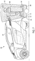
- FIG. 7 is a drawing of the system of FIG. 5 showing a convertible cover of the docking station for surrounding at least a portion of the robot according to an embodiment of the present invention
- FIG. 8 is a drawing of the system of FIG. 5 showing a movable cover of the docking station for covering at least a portion of the robot according to an embodiment of the present invention
- FIG. 9 is a drawing of an interior of the vehicle of FIG. 1 including a touchscreen according to an embodiment of the present invention.
- FIG. 10 is a drawing of the touchscreen shown in FIG. 9 illustrating various options for programming a robot while the robot is attached to a docking station according to an embodiment of the present invention
- FIG. 11 is a drawing of the touchscreen shown in FIG. 9 illustrating various options for controlling a robot while the robot is attached to a docking station according to an embodiment of the present invention
- FIG. 12 is a flowchart illustrating a method for controlling a robot by a vehicle according to an embodiment of the present invention.
- FIG. 13 is a flowchart illustrating a method for controlling power transfer between a vehicle and a robot according to an embodiment of the present invention.
- the systems and methods provide several benefits and advantages such as providing a relatively easy way to transport a robot between locations. This provides benefits and advantages such as allowing a robot to be used in multiple locations with relatively little effort. Allowing the robot to be transported and used in multiple locations provides benefits and advantages such as allowing elderly or disabled persons to bring personal assistant robots along with them on errands so that the robots can help perform the errands.
- the systems and methods provide additional benefits and advantages such as allowing the robots to be controlled from a cabin of a vehicle. This provides additional benefits and advantages such as allowing elderly or disabled persons to control the robot without having to leave the cabin of the vehicle. This is especially useful in unpleasant weather conditions such as during rainfall or extreme temperatures.
- An exemplary system includes a vehicle, a robot and a docking station.
- the docking station includes a robot dock for physically connecting the robot to the vehicle.
- the docking station also includes a power port for allowing power to transfer between the robot and the vehicle and a communication port for allowing communications to transfer between the robot and the vehicle.
- the vehicle includes a power source for storing or generating power, an input/output (I/O) port for transmitting and/or receiving messages and an electronic control unit (ECU).
- the ECU may control the power source to transmit and/or receive power from the robot.
- the ECU may also program and/or control the robot via the I/O port.
- a system 100 includes a vehicle 102 , a docking station 104 , and a robot 106 .
- the docking station 104 allows the robot 106 to be mechanically and electrically connected to the vehicle 102 .
- the vehicle 102 may transport the robot 106 , may provide power to the robot 106 and may program and/or control operations of the robot 106 .
- the vehicle 102 includes an ECU 108 and a memory 110 .
- the vehicle 102 also includes an input device 112 , an output device 114 , a power source 116 and an I/O port 118 .
- the vehicle 102 also includes a body 120 .
- the ECU 108 may be electrically coupled to some or all of the components or devices of the vehicle 102 .
- the ECU 108 can include one or more processors or controllers specifically designed for automotive systems, and the functions of the ECU 108 can be implemented in a single ECU or in multiple ECUs.
- the ECU 108 may receive data from components or devices of the vehicle 102 , may determine data based on the received data and may control the operations of components or devices based on the received or determined data.
- the memory 110 may include one or any combination of the following: a RAM or other volatile or nonvolatile memory, a non-transitory memory or a data storage device, such as a hard disk drive, a solid state disk drive, a hybrid disk drive, a remote cloud or other appropriate data storage device or system.
- the memory 110 may store machine-readable instructions executable by the ECU 108 and may store any other data as instructed by the ECU 108 .
- the input device 112 may include any input device capable of receiving user input.
- the input device 112 may include a button, a knob, a dial, a touchscreen, a touchpad, a microphone or the like.
- the input device 112 may be coupled to the ECU 108 such that the ECU 108 can receive user input via the input device 112 .
- the output device 114 may include any output device capable of outputting data to a user.
- the output device 114 may include a speaker, a display, a touchscreen, a refreshable braille display or the like.
- the power source 116 may include any power source capable of storing and/or generating electrical power.
- the power source 116 may include a battery or a fuel cell for storing electrical power.
- the power source 116 may also or instead include a motor generator capable of converting electrical power into mechanical power and of converting mechanical power into electrical power.
- the power source 116 may also or instead include an engine coupled to a generator.
- the power source 116 may provide power for propelling the vehicle 102 and for being distributed to the robot 106 .
- the power source 116 may be directly or indirectly coupled to two or more wheels and may cause the wheels to rotate in response to receiving power from the power source 116 .
- the I/O port 118 may include any device or port capable of communicating with an external device or network via a wired connection and/or a wireless connection.
- the I/O port 118 may communicate with at least one of the docking station 104 or the robot 106 via a CAN bus, 3G protocols, 4G protocols, 5G protocols, USB protocols, Bluetooth protocols, 802.11 (Wi-Fi) protocols, dedicated short range communication protocols (DSRC) or the like.
- the I/O port 118 may include a physical portion and a logical portion.
- the physical portion may transmit and/or receive signals, for example, via an antenna or a wired connection.
- the logical portion may convert signals or messages between protocols, for example, from a first protocol received by the ECU 108 to a second protocol received by the robot 106 .
- the body 120 includes a mechanical structure that encloses and/or supports components of the vehicle 102 and/or the robot 106 .
- the body 120 may be suspended above a ground surface by two or more tires (not shown).
- the docking station 104 includes a robot dock 122 , a power port 124 and a communication port 126 . In some embodiments, the docking station 104 may only include one of the power port 124 or the communication port 126 .
- the docking station 104 may be provided as a separate component from the vehicle 102 or may be included as part of the vehicle 102 . For example, the docking station 104 may be sold to a user who already owns the vehicle 102 or the features of the docking station 104 may be integral to the vehicle 102 .
- the robot dock 122 includes a physical structure that may be mechanically coupled to the body 120 of the vehicle 102 and mechanically coupled to the robot 106 .
- the robot dock 122 may be mechanically coupled to the body 120 and/or the robot 106 in a variety of ways, some of which will be described below.
- the power port 124 may be coupled to the power source 116 of the vehicle 102 .
- the power port 124 may also be coupled to the robot 106 .
- the power port 124 may receive a power signal from the power source 116 and allow the power signal to propagate to the robot 106 to charge the robot.
- the power port 124 may receive a power signal from the robot 106 and allow the signal to propagate to the power source 116 to provide power to the power source 116 .
- the communication port 126 may be coupled to the I/O port 118 of the vehicle 102 .
- the communication port 126 may also be coupled to the robot 106 .
- the communication port 126 may receive a communication signal from the I/O port 118 and allow the signal to propagate to the robot 106 and may receive a communication signal from the robot 106 and allow the signal to propagate to the I/O port 118 .
- the power port 124 and/or the communication port 126 may actively receive the signals and re-transmit the signals.
- the I/O port 118 of the vehicle 102 may communicate directly with the robot 106 without the signal propagating through the communication port 126 .
- the ECU 108 may control power distribution between the power source 116 and the robot 106 .
- the ECU 108 may determine that the robot 106 has a low charge and may control the power source 116 to provide power to the robot 106 via the power port 124 .
- the ECU 108 may determine that the power source 116 , such as a battery, has a low charge and, in response, may control the power source 116 to receive power from the robot 106 via the power port 124 .
- the ECU 108 may program and/or control the robot 106 via the communication port 126 .
- a user may provide input data corresponding to a desired mission of the robot 106 using the input device 112 .
- the ECU 108 may receive the desired mission and may program the robot 106 to perform the desired mission.
- the robot dock 122 may have controllable components such as actuators for connecting and disconnecting the robot 106 from the robot dock 122 .
- the ECU 108 may control the robot dock 122 to connect to the robot 106 and to disconnect from the robot 106 .
- the docking station 104 may include the robot dock 122 and a combined power port/communication port 124 , 126 .
- the power port 124 and the communication port 126 may be included as a single port, as shown in FIG. 2 .
- the power port 124 and the communication port 126 may be separate ports.
- the robot dock 122 may include an arm 200 , a pincher 202 , a first actuator 204 , and a second actuator 206 .
- the arm 200 may be mechanically coupled to the body 120 of the vehicle 102 .
- the arm 200 may be coupled to a trailer hitch of the body 120 , may be bolted to the body 120 , may be welded to the body 120 or may be coupled to the body 120 in another manner.
- the robot dock 122 may also include a lock, for example, positioned on the arm 200 of the robot dock 122 .
- the lock may include any locking mechanism capable of being connected to the robot 106 and resisting separation of the robot 106 from the trailer robot dock 122 .
- the lock may be locked and unlocked by use of a physical or electric key, by entering a code or combination, by a control signal sent from the ECU 108 of the vehicle 102 or the like.
- An exemplary lock 340 is illustrated in FIGS. 5 and 6 .
- the robot dock 122 and/or the vehicle 102 may also include a cover.
- An exemplary convertible cover 350 is shown in FIG. 7 .
- the cover may be coupled to any portion of the robot dock 122 and/or the vehicle 102 , such as to the arm 200 or to another arm (not shown).
- the cover may have a storage position in which the robot 306 is allowed to freely move into and out of the robot dock 122 .
- the cover may be movable to a covered position in which it surrounds at least a portion of the robot 106 .
- the cover may be controlled by the ECU 108 of the vehicle 102 and/or may be manually moved between the storage position and the covered position.
- the first actuator 204 may be positioned between a first finger 203 and a second finger 205 of the pincher 202 .
- the first actuator 204 may actuate the pincher 202 between an uncoupled position, as shown in FIG. 2 , and a coupled position.
- the robot 106 may freely move into and out of an area defined between the fingers 203 , 205 .
- the robot 106 may roll or walk towards the pincher 202 such that at least a portion of the robot 106 is positioned between the fingers 203 , 205 .
- the pincher 202 is shown in the coupled position about the robot 106 .
- the first actuator 204 may contract, causing the fingers 203 , 205 of the pincher 202 to move closer together.
- the fingers 203 , 205 may close around a portion of the robot 106 .
- the fingers 203 , 205 resist separation of the robot 106 from the pincher 202 .
- the power port/communication port 124 , 126 may be positioned on the finger 203 .
- the robot 106 may include a connector 208 designed to connect to the power port/communication port 124 , 126 of the docking station 104 .
- the power port/communication port 124 , 126 may be received by the connector 208 of the robot 106 .
- power and/or communications may be transmitted between the vehicle 102 and the robot 106 .
- the docking station 104 may include a separate power port and a communication port and the robot 106 may also include a separate power port and a communication port.
- power may transfer between the docking station 104 and the robot 106 via the power port and communications may transfer between the docking station 104 and the robot 106 via the separate communication port.
- the second actuator 206 may be coupled between the body 120 of the vehicle 102 and the arm 200 .
- the second actuator 206 may move the arm 200 between a lifted position, as shown in FIG. 2 , and a grounded position. In order to move the arm from the lifted position to the grounded position, the second actuator 206 may become compressed. As the second actuator 206 is compressed, the end of the arm 200 connected to the pincher 202 moves towards a ground surface 230 .
- the ECU 108 may cause the second actuator 206 to move the arm 200 to the grounded position.
- the ECU 108 may cause the first actuator 204 to actuate the pincher 202 to the uncoupled position.
- the robot 106 may freely move away from the vehicle 102 and begin performing its mission.
- FIG. 5 another system 300 includes a vehicle 302 , a docking station 304 and a robot 306 .
- the vehicle 302 may have similar features as the vehicle 102 of FIG. 2 and the robot 306 may have similar features as the robot 106 of FIG. 2 .
- the docking station 304 includes a trailer 322 as the robot dock and also includes a power port/communication port 324 , 326 .
- the docking station 304 further includes a cable 348 coupled to the power port/communication port 324 , 326 and designed to be coupled to an input/output port (not shown) of the vehicle 302 .
- the docking station 304 may be electrically coupled to the vehicle 302 in any other fashion.
- the trailer 322 includes a hitch connector 336 that is designed to be attached to a trailer hitch 338 of the vehicle 302 .
- the docking station 304 can be electrically coupled to the ECU of the vehicle 302 via the cable 348 and can be mechanically coupled to the vehicle 302 via the hitch connector 336 and the trailer hitch 338 .
- the docking station 304 can also be separated from the vehicle 302 by disconnecting the cable 348 from the vehicle 302 and by disconnecting the hitch connector 336 from the trailer hitch 338 .
- the docking station 304 may be stored separately from the vehicle 302 and may be coupled to the vehicle 302 when desired.
- the robot 306 includes a connector 344 that is designed to be connected to the power port/communication port 324 , 326 .
- the power port/communication port 324 , 326 is connected to the connector 344 of the robot 306 , power and/or communications may transfer between the docking station 304 and the robot 306 .
- the cable 348 is connected to the vehicle 302 , power and/or communications may be transmitted between the vehicle 302 and the robot 306 via the docking station 304 .
- the power port/communication port 324 , 326 and the connector 344 of the robot 306 may include various types of connectors.
- the power port/communication port 324 , 326 and the connector 344 may be coupled together via a cable and one or more physical connectors.
- the power port/communication port 324 , 326 and the connector 344 may be directly coupled via one or more physical connectors.
- the power port/communication port 324 , 326 may transmit power and/or communications to the robot 306 wirelessly.
- the power portion of the power port/communication port 324 , 326 may be designed to transmit and/or receive an inductive charge and the connector 344 of the robot 306 may be designed to receive and/or transmit an inductive charge.
- the trailer 322 includes a platform 330 , a wheel 332 and a ramp 334 .
- the wheel 332 is coupled to the platform 330 and supports the platform 330 above a ground surface 346 .
- the hitch connector 336 of the trailer 322 is coupled to the trailer hitch 338 of the vehicle 302 , the wheel 332 may rotate as the vehicle 302 moves, allowing the trailer 322 to move along the ground surface 346 along with the vehicle 302 .
- the trailer 322 may be designed such that the platform 330 can support the robot 306 above the ground surface 346 . Thus, when the robot 306 is positioned on the platform 330 , the vehicle 302 may transport the robot 306 between various locations.
- the trailer 322 may include one or more sides 349 extending from the platform 330 in a direction away from the ground surface 346 .
- the one or more sides 349 may be positioned proximate to the robot 306 when the robot 306 is positioned on the platform 330 .
- the one or more sides 349 may be positioned within 1 foot of the robot 306 , within half a foot of the robot 306 , within 3 inches of the robot 306 , may be in contact with the robot 306 or the like.
- the sides 349 may contact the robot 306 when the robot 306 moves relative to the trailer 322 , thus reducing the likelihood of the robot 306 falling off of the platform 330 .
- the ramp 334 may have a first end coupled to the platform 330 and may include a second end.
- the ramp 334 may be positioned in a loading position as shown in FIG. 5 .
- the second end of the ramp 334 may contact the ground surface 346 . This provides a surface upon which the robot 306 may roll, walk, or otherwise move from a location on the ground surface 346 to a location on the platform 330 .
- the trailer 322 may include an actuator 342 coupled to the ramp 334 and one or more of the sides 349 or the platform 330 .
- the actuator 342 may move the ramp 334 from the loading position to a storage position.
- the trailer 322 may not include an actuator and the ramp 334 may be manually moved between the loading position and the storage position.
- the ramp 334 is positioned in the storage position.
- the second end of the ramp 334 is moved away from the ground surface 346 and held in the position away from the ground surface 346 .
- the ramp 334 may be latched or otherwise coupled to one or more of the sides 349 or the platform 330 .
- the trailer 322 may also include a lock 340 .
- the lock 340 may include any locking mechanism capable of being connected to the robot 306 and resisting separation of the robot 306 from the trailer 322 .
- the lock may be locked and unlocked by use of a physical or electric key, by entering a code or combination, by a control signal sent from the ECU of the vehicle 302 or the like.
- the vehicle 302 may include an input device for receiving an identifier of a user.
- the identifier may include a character string, a fob, a biometric or the like.
- the ECU of the vehicle 302 may receive the identifier via the input device.
- the ECU may control the lock 340 to switch from the locked state to the unlocked state or vice versa so long as the identifier corresponds to an authorized user.
- the lock 340 may be coupled to the robot 306 in various manners.
- the lock 340 may include a chain that extends through an aperture of the robot 306 .
- the lock 340 may also or instead include a mechanism that can be inserted into a cavity of the robot 306 and expanded such that it cannot be removed from the cavity while locked. Because the robot 306 may not be fully enclosed by the trailer 322 , the lock 340 may reduce the likelihood of the robot 306 being removed from the trailer 322 by an unauthorized person.
- the docking station 304 may also include a convertible cover 350 .
- the convertible cover 350 may be coupled to one or more of the sides 349 , the platform 330 or the ramp 334 .
- the convertible cover 350 may have a storage position in which it is compressed in such a way as to allow the robot 306 to be loaded onto the trailer 322 .
- the convertible cover 350 may be located substantially within an area defined by the sides 349 of the trailer 322 .
- the convertible cover 350 may be controlled to be in a covered position in which it is expanded and surrounds at least a portion of the robot 306 , as shown in FIG. 7 .
- the convertible cover 350 may be controlled by the ECU of the vehicle 302 and/or may be manually moved between the storage position and the covered position.
- the convertible cover 350 may include any material such as plastic, glass, fabric, metal or the like.
- the convertible cover 350 may include a metal skeleton and a fabric skin.
- the vehicle 302 or the docking station 304 may include a movable cover 352 .
- the movable cover 352 may be coupled to the vehicle 302 or the docking station 304 via one or more posts.
- the movable cover 352 is coupled to the vehicle 302 by a first post 356 , a second post 358 and a third post 360 .
- the first post 356 and the second post 358 are coupled together by a joint 362
- the second post 358 and the third post 360 are coupled together by a joint 364 .
- the joints 362 , 364 allow relative movement of the posts 356 , 358 , 360 .
- the posts 356 , 358 , 360 may be manipulated to move the movable cover 352 from a covered position, as shown in FIG. 8 , to an uncovered position where the movable cover 352 may not surround the robot 306 .
- the movable cover 352 may be positioned in the covered position in order to protect at least a portion of the robot 306 from weather elements such as direct sunlight and/or rain.
- the movable cover 352 may also protect the robot 306 from theft.
- the movable cover 352 may include any material such as plastic, glass, fabric, metal or the like.
- the actuators 366 , 368 may be used to electronically control the position of the movable cover 352 .
- the actuator 366 may be coupled between the first post 356 and the second post 358 and may be controlled to move the second post 358 relative to the first post 356 .
- the actuator 368 may be coupled between the second post 358 and the third post 360 and may be controlled to move the third post 360 relative to the second post 358 .
- the ECU may control the actuators 366 , 368 to move the movable cover 352 between the covered position and the uncovered position.
- the ECU may control the actuators 366 , 368 to cause the movable cover 352 to be in the open position in response to receiving user input corresponding to a request to the robot 306 to leave the docking station 304 and/or in response to determining that the robot 306 should depart the docking station 304 .
- the movable cover 352 may remain coupled to the vehicle 302 or may be disconnected from the vehicle 302 .
- the movable cover 352 may be disconnected from one or more of the posts 356 , 358 , 360 and, in some embodiments, one or more of the posts 356 , 358 , 360 may be disconnected from the vehicle 302 .
- FIG. 9 a view of a cabin of the vehicle 102 is shown.
- the vehicle 102 includes a touchscreen 180 that performs the functions of the input device 112 and the output device 114 .
- FIGS. 1 and 10 another view of the touchscreen 180 illustrates features that can be performed using the system 100 .
- the touchscreen 180 includes several options for receiving user input.
- the touchscreen 180 includes a power button 400 , mode select buttons 402 , a microphone 406 and a new task 414 for receiving user input corresponding to a new task to be performed by the robot 106 .
- the touchscreen 180 also provides information corresponding to the robot 106 such as currently scheduled tasks 408 , 410 and 412 and a current battery status 422 of the robot 106 .
- the tasks shown in FIG. 10 may correspond to a mission of the robot 106 that include tasks related to entering a grocery store and retrieving groceries. As shown, the mission currently includes a first task 408 to retrieve Jamboree brand apples, a second task to retrieve Newport brand bread and a third task to retrieve Bristol brand cereal.
- the touchscreen 180 provides an option for a user to edit or cancel each of the assigned tasks.
- the touchscreen 180 provides an edit/cancel button 416 corresponding to the first task 408 , an edit/cancel button 418 corresponding to the second task 410 and an edit/cancel button 420 corresponding to the third task 412 .
- a user is in the process of requesting the new task 414 .
- a user may provide input to the touchscreen 180 using a keypad or a displayed keyboard to type in the desired input.
- a user may provide input by speaking a command into the microphone 406 .
- Input may be provided in any other manner as known in the art, such as direct teleoperation of joints, positions, or the like.
- the screen displayed in FIG. 10 may correspond to a situation where the robot 106 is being programmed prior to beginning the mission.
- the user may provide one or more tasks to be performed during the mission via the touchscreen 180 .
- the ECU 108 may receive the desired tasks and may program the robot 106 accordingly.
- the user may select a begin mission button 424 corresponding to a request for the robot to begin performing the tasks of the mission.
- the touchscreen 180 may display data 434 corresponding to a current status of the robot 106 .
- the data 434 displayed by the touchscreen 180 may correspond to a current view of the robot 106 .
- the touchscreen 180 may remove tasks from the task list as they are performed. For example, as the current task 412 includes retrieving Bristol brand cereal and the new task 414 includes retrieving Anton brand milk, the user may determine that the first task 408 and the second task 410 shown in FIG. 10 have been performed as they are no longer shown in the task list.
- the touchscreen 180 may also provide the edit/cancel button 420 to allow the user to select to edit or cancel the third task 412 , an edit/cancel button 430 to allow the user to select to edit or cancel the new task 414 and a new task field 432 for allowing a user to add a task to the current mission.
- the user may monitor the status of the mission of the robot 106 and may change the mission of the robot 106 while the robot 106 is undocked from the docking station 104 via the touchscreen 180 .
- the touchscreen 180 may also display at least one of an estimated time for completion or an estimated energy usage for each task.
- the touchscreen 180 may also provide alternatives to a user, such as suggesting Birmingham brand cereal if Bristol brand cereal is unavailable or if Birmingham brand cereal is on sale.
- a method 500 for controlling a robot, such as the robot 106 of FIG. 1 , using a vehicle, such as the vehicle 102 of FIG. 1 is shown.
- the method 500 may be performed, for example, by an ECU of the vehicle 102 .
- the ECU may receive, via an input device of the vehicle, user input corresponding to a request for the robot to perform a mission.
- the user input may include one or more requested tasks to be completed during the mission.
- the user input may correspond to a selection of a predetermined task of the robot.
- the robot may be preprogrammed to perform certain missions. The user may select one or more of the missions and request that the robot perform the selected mission(s).
- the ECU may determine whether the robot has sufficient power to complete the mission. For example, the ECU may first predict or determine an amount of power that the robot will require to perform the mission. The ECU may predict or determine the required amount of power based on the tasks to be performed during the mission and based on power usage statistics of the robot. For example, if the robot uses half of a kilowatt-hour (kWH) per five minutes and the mission will require 30 minutes to complete, the ECU may predict that the robot will require 3 kWH of power to complete the mission. In some embodiments, the ECU may be designed to predict that the mission will require more power than is likely to be used. For example, the ECU may be designed to predict that any given mission will require ten percent (10%) more, or 15% more, or 25% more power than it is likely to use during the mission.
- kWH kilowatt-hour
- the ECU may compare the predicted or determined amount of power to the current power level of the robot. If the predicted or determined amount of power to be used during the mission is less than the current power level of the robot, the ECU may determine that the robot requires additional power to complete the mission.
- the ECU may control a power source of the vehicle to provide power to the robot.
- the ECU may control a battery of the vehicle to provide electrical power to the robot via a power port of the docking station.
- the ECU may control an engine of a vehicle to generate mechanical power and a generator to convert the mechanical power into electrical power to be provided to the robot via the power port of the docking station.
- the ECU may program the robot to perform the mission.
- the ECU may provide tasks to the robot in the same format that they are received via the input device.
- the ECU may convert or break down the tasks into a different protocol or smaller tasks and provide the converted task data to the robot.
- a user may provide the task of retrieving Bristol brand cereal from the grocery store.
- the ECU may determine which lower-level tasks must be completed in order to complete the task of retrieving the Bristol brand cereal. For example, the ECU may determine that the robot must first be undocked from the docking station, must then proceed 50 feet away from the docking station to arrive at the door of the grocery store, etc. The ECU may then program the robot to complete these lower level tasks.
- the ECU may determine when the robot should be undocked from the docking station and begin performing the mission. For example, the ECU may determine that the robot should begin the mission when the vehicle arrives at the destination, such as a parking lot of the grocery store.
- the ECU may determine that the robot should begin the mission when the ECU determines that the vehicle is parked at a location that is within a predetermined distance of the destination.
- the destination may be the grocery store and the ECU may determine that the robot should begin the mission when its vehicle is parked at a location within 500 feet of the grocery store.
- the ECU may determine that the robot should begin the mission in response to receiving user input corresponding to a request for the mission to begin.
- the ECU may control the docking station to undock and disconnect from the robot in block 510 .
- the ECU may also establish wireless communications with the robot at or about the time of undocking.
- the ECU may control, for example, an actuator coupled to two fingers of a pincher to move from the coupled position to the uncoupled position to allow the robot to separate from the pincher.
- the ECU may control an actuator coupled to a ramp of a trailer to be moved to a loading position, also allowing the robot to separate from the trailer.
- the ECU may or may not control the docking station to return to a previous state.
- the ECU may control an actuator that is coupled to a trailer to move a ramp of the trailer to the storage position.
- the robot may wirelessly provide status updates to the ECU.
- the ECU may provide the status updates to the user via an output device in block 512 .
- the status updates may include prognostic data corresponding to the robot, such as a current power level, whether mobility of the robot has been disrupted or the like.
- the status updates may also include image data corresponding to the robot, such as image data captured by a camera coupled to the robot.
- the status updates may also include data indicating a status of each task included in the mission.
- the robot may transmit this data to the communication port of the docking station, and the docking station may transmit the data to the ECU.
- the ECU may monitor the status of the robot and may abort and/or change the mission if necessary. For example, if the ECU determines that the current power level of the robot is no longer sufficient to complete the mission, the ECU may instruct the robot to abort the mission and/or to eliminate tasks from the mission.
- the ECU may receive user input, such as via an input device, corresponding to a user request to change the mission.
- the user may request an additional task to be performed during the mission, such as for the robot to retrieve an additional grocery item.
- the ECU may reprogram the robot wirelessly in response to receiving the user request to change the mission.
- the ECU may first ensure that the robot is capable of completing the new task prior to programming the robot to perform the new task. For example, the ECU may ensure that the robot has sufficient battery power to complete the task. If the robot has insufficient battery power to complete the task, the ECU may not program the robot to perform the new task and may inform the user that the new task cannot be completed. At this point, the user may be provided with an option to replace an existing task with the new task.
- the robot may notify the ECU that the mission is completed in block 518 .
- the robot may also or instead notify the ECU when it is within a predetermined distance of the vehicle or the docking station. For example, after completing the mission, the robot may travel towards the vehicle. As the robot approaches the vehicle and is within a predetermined distance, such as 2 feet, 5 feet, 10 feet, 20 feet or the like, the robot may transmit data indicating that the robot is within the predetermined distance. In some embodiments, a sensor of the vehicle may detect that the robot is within the predetermined distance and may provide this data to the ECU.
- the ECU may prepare the dock to receive the robot in block 520 . For example, if the docking station has changed states after the robot has been undocked (i.e., a ramp has been returned to a storage position) then the ECU may control the docking station to be in a state in which the robot can be docked. For example, the ECU may control an actuator coupled to fingers of a pincher to be in an uncoupled position for receiving the robot. As another example, the ECU may control an actuator coupled to a ramp of a trailer to move the ramp to the loading position.
- the robot may move into a position where it can be docked to the docking station.
- the robot may move into an area between the fingers of a pincher of a robot dock.
- the robot may roll or walk up a ramp of a trailer onto a platform.
- the ECU may control the docking station to transition between states.
- the ECU may control an actuator coupled to fingers of a pincher to move to a coupled position or may control an actuator coupled to a ramp of a trailer to move to a storage position.
- a user may be required to manually dock the robot to the docking station.
- the ECU may automatically control a lock of the docking station to lock to the robot, and in some embodiments, a user may be required to manually lock the robot to the docking station. In some embodiments, no lock is present and the robot is not locked to the docking station.
- the robot may be automatically coupled to the power port and/or communication port of the docking station when it is docked.
- a connector of the robot may be in contact with a power port and/or a communication port of the docking station, allowing the propagation of power and/or communication signals between the robot and the vehicle.
- the robot when the robot is docked, it may be capable of receiving wireless communications or power, such as via inductive charging.
- the ECU may determine when the robot has been docked (i.e., corresponding to the robot being electrically and physically coupled to the docking station) and may begin local power transfer to the robot and/or communications with the robot via the docking station in block 522 .
- the ECU may determine or predict a route or a route set of the vehicle.
- Route sets are known in the art and may include a combination of routes.
- a route set may include a trip from the driver's home to a driver's workplace in the morning, a trip to a restaurant for lunch, and a trip from the driver's workplace to the driver's home in the evening.
- Route and route set prediction methods and systems are known in the art and will not be described herein.
- the ECU may determine or predict an amount of power required by the vehicle to complete the route set. For example, the ECU may determine the amount of power required based on the topology of the roads along the route set, the distance of the route set, whether the vehicle can receive additional power at any of the destinations of the route set, the energy efficiency of the vehicle or the like.
- the ECU may determine or predict missions that will be requested of the robot before the route set is complete.
- Missions may be determined or predicted based on historical data as well as any data provided to the ECU via the input device.
- the historical data and/or data provided to the ECU may include predicted or provided destinations along a route set, missions provided to the ECU via the input device, data detected and stored corresponding to previous missions of the robot or the like.
- the ECU may determine that a destination of the route set is a grocery store.
- the ECU may predict that the robot will be requested to retrieve groceries from the grocery store based on the grocery store being a destination and similar missions being requested when previous destinations were grocery stores.
- the ECU may store data indicating that the driver typically requests that a particular mission be performed every weekday at noon. The ECU may predict that the same or a similar mission may be performed at noon every weekday.
- the ECU may determine or predict the amount of power required to complete the mission in block 608 . As described above, this may be based on information such as the particular tasks to be completed, the energy efficiency of the robot, an amount of time required to complete the tasks or the like.
- the ECU may control the power supply of the vehicle to receive a sufficient amount of power for the vehicle to be able to complete the route set and the robot to be able to complete any missions in block 610 .
- the ECU may control the power supply of the vehicle to receive an amount of power at least as large as the sum of the amount of power required for the vehicle to complete the route set and the power required for the robot to complete the missions.
- the ECU may control the power supply to receive more power than required to complete the route set and the missions.
- the ECU may control the power supply to receive 10%, 20%, 30% or the like more power than required to complete the route set in missions. This provides sufficient power in case a detour is taken, a mission requires more power than predicted, unexpected missions are requested or the like.
- the ECU may control the power supply of the vehicle to ensure that the power supply retains sufficient power to complete the route set in block 612 .
- it may be more critical for the vehicle to be able to complete the route set than for the robot to be able to complete all missions. If the robot is unable to complete all missions, the vehicle may be able to travel to a charging station or other power source to receive additional power for itself and/or for the robot. However, if the vehicle is unable to complete the route set, it may be unable to travel to a charging station or other power source.
- the ECU may also control the power supply to provide sufficient power to the robot to complete the missions. For example, if 5 kWH are required for the robot to complete a mission and the robot only includes 3 kWH of power, the ECU may control the power supply of the vehicle to provide at least an additional 2 kWH to the robot. In some embodiments, the ECU may control the power supply to provide additional power to the robot, such as 10% above the required amount of power, 20% above the required amount of power or the like.
- the ECU may control the power supply to receive power from the robot. For example, the robot may continuously store a predetermined amount of power. Upon determining that the vehicle cannot complete the route set on the current amount of power in the power supply, the ECU may control the power supply to receive, and/or the robot to provide, at least some of the stored amount of power of the robot.
Landscapes
- Engineering & Computer Science (AREA)
- Mechanical Engineering (AREA)
- Transportation (AREA)
- Robotics (AREA)
- Power Engineering (AREA)
- Automation & Control Theory (AREA)
- Physics & Mathematics (AREA)
- Artificial Intelligence (AREA)
- Electric Propulsion And Braking For Vehicles (AREA)
- Evolutionary Computation (AREA)
- Fuzzy Systems (AREA)
- Mathematical Physics (AREA)
- Software Systems (AREA)
- Manipulator (AREA)
Abstract
Description
Claims (18)
Priority Applications (1)
| Application Number | Priority Date | Filing Date | Title |
|---|---|---|---|
| US15/225,709 US10562432B2 (en) | 2016-08-01 | 2016-08-01 | Vehicle docking and control systems for robots |
Applications Claiming Priority (1)
| Application Number | Priority Date | Filing Date | Title |
|---|---|---|---|
| US15/225,709 US10562432B2 (en) | 2016-08-01 | 2016-08-01 | Vehicle docking and control systems for robots |
Publications (2)
| Publication Number | Publication Date |
|---|---|
| US20180029516A1 US20180029516A1 (en) | 2018-02-01 |
| US10562432B2 true US10562432B2 (en) | 2020-02-18 |
Family
ID=61011999
Family Applications (1)
| Application Number | Title | Priority Date | Filing Date |
|---|---|---|---|
| US15/225,709 Expired - Fee Related US10562432B2 (en) | 2016-08-01 | 2016-08-01 | Vehicle docking and control systems for robots |
Country Status (1)
| Country | Link |
|---|---|
| US (1) | US10562432B2 (en) |
Cited By (2)
| Publication number | Priority date | Publication date | Assignee | Title |
|---|---|---|---|---|
| US11390180B2 (en) * | 2018-03-08 | 2022-07-19 | Moderntec Co., Ltd. | Automatic handle device |
| DE102022105321A1 (en) | 2022-03-08 | 2023-09-14 | Audi Aktiengesellschaft | Device and method for transporting a robot |
Families Citing this family (5)
| Publication number | Priority date | Publication date | Assignee | Title |
|---|---|---|---|---|
| EP3413424B1 (en) * | 2017-06-09 | 2020-12-23 | Andreas Stihl AG & Co. KG | Method for determining an item of information for operating a battery, method for determining different times for charging different batteries and electric gardening and/or forest system |
| US20220009086A1 (en) * | 2018-12-09 | 2022-01-13 | Pramod Kumar Verma | Stick device and user interface |
| JP7081537B2 (en) * | 2019-03-12 | 2022-06-07 | トヨタ自動車株式会社 | Processing equipment, processing method and processing program |
| CN110863400A (en) * | 2019-12-04 | 2020-03-06 | 韩斌 | Electrified highway modified by CMIW method |
| CN110952822B (en) * | 2019-12-18 | 2021-05-07 | 温州鑫锐翔科技有限公司 | Electric automobile charging parking stall |
Citations (18)
| Publication number | Priority date | Publication date | Assignee | Title |
|---|---|---|---|---|
| US4777416A (en) | 1986-05-16 | 1988-10-11 | Denning Mobile Robotics, Inc. | Recharge docking system for mobile robot |
| US7527282B2 (en) | 2007-05-23 | 2009-05-05 | Gilbert Larry D | Transporter |
| US20100034628A1 (en) * | 2008-08-05 | 2010-02-11 | Ray H Keith | Mobile Wheelchair Carrier |
| US7896113B1 (en) | 2007-05-12 | 2011-03-01 | Fernando Ramirez | Police robotic system |
| US7999506B1 (en) | 2008-04-09 | 2011-08-16 | SeventhDigit Corporation | System to automatically recharge vehicles with batteries |
| US20120233062A1 (en) | 2011-03-11 | 2012-09-13 | Kevin Terrill Cornish | Method and process for an electric vehicle charging system to automatically engage the charging apparatus of an electric vehicle |
| US20120286730A1 (en) | 2011-05-11 | 2012-11-15 | Richard William Bonny | Automatic Recharging Robot for Electric and Hybrid Vehicles |
| US8430192B2 (en) | 2010-01-04 | 2013-04-30 | Carla R. Gillett | Robotic omniwheel vehicle |
| US8509981B2 (en) | 2011-05-25 | 2013-08-13 | Toyota Motor Engineering & Manufacturing North America, Inc. | Docking stations for automated guided vehicles |
| US20130257145A1 (en) * | 2012-03-30 | 2013-10-03 | Elwha Llc | Method and apparatus for supplying auxiliary electrical power to an electric or hybrid vehicle |
| US8749196B2 (en) | 2004-01-21 | 2014-06-10 | Irobot Corporation | Autonomous robot auto-docking and energy management systems and methods |
| WO2014181083A1 (en) | 2013-05-10 | 2014-11-13 | Dyson Technology Limited | Apparatus for guiding an autonomous vehicle towards a docking station |
| US9193065B2 (en) | 2008-07-10 | 2015-11-24 | Intouch Technologies, Inc. | Docking system for a tele-presence robot |
| US20160196756A1 (en) * | 2014-08-05 | 2016-07-07 | Qualcomm Incorporated | Piggybacking Unmanned Aerial Vehicle |
| US20160257401A1 (en) * | 2015-03-02 | 2016-09-08 | Amazon Technologies, Inc. | Landing of unmanned aerial vehicles on transportation vehicles for transport |
| US9638497B2 (en) * | 2011-10-06 | 2017-05-02 | Harris Corporation | Improvised explosive device defeat system |
| US20170129603A1 (en) * | 2015-11-10 | 2017-05-11 | Matternet, Inc. | Methods and systems for transportation using unmanned aerial vehicles |
| US20170355459A1 (en) * | 2016-06-09 | 2017-12-14 | International Business Machines Corporation | Unmanned aerial vehicle coupling apparatus for drone coupling with vehicles |
-
2016
- 2016-08-01 US US15/225,709 patent/US10562432B2/en not_active Expired - Fee Related
Patent Citations (18)
| Publication number | Priority date | Publication date | Assignee | Title |
|---|---|---|---|---|
| US4777416A (en) | 1986-05-16 | 1988-10-11 | Denning Mobile Robotics, Inc. | Recharge docking system for mobile robot |
| US8749196B2 (en) | 2004-01-21 | 2014-06-10 | Irobot Corporation | Autonomous robot auto-docking and energy management systems and methods |
| US7896113B1 (en) | 2007-05-12 | 2011-03-01 | Fernando Ramirez | Police robotic system |
| US7527282B2 (en) | 2007-05-23 | 2009-05-05 | Gilbert Larry D | Transporter |
| US7999506B1 (en) | 2008-04-09 | 2011-08-16 | SeventhDigit Corporation | System to automatically recharge vehicles with batteries |
| US9193065B2 (en) | 2008-07-10 | 2015-11-24 | Intouch Technologies, Inc. | Docking system for a tele-presence robot |
| US20100034628A1 (en) * | 2008-08-05 | 2010-02-11 | Ray H Keith | Mobile Wheelchair Carrier |
| US8430192B2 (en) | 2010-01-04 | 2013-04-30 | Carla R. Gillett | Robotic omniwheel vehicle |
| US20120233062A1 (en) | 2011-03-11 | 2012-09-13 | Kevin Terrill Cornish | Method and process for an electric vehicle charging system to automatically engage the charging apparatus of an electric vehicle |
| US20120286730A1 (en) | 2011-05-11 | 2012-11-15 | Richard William Bonny | Automatic Recharging Robot for Electric and Hybrid Vehicles |
| US8509981B2 (en) | 2011-05-25 | 2013-08-13 | Toyota Motor Engineering & Manufacturing North America, Inc. | Docking stations for automated guided vehicles |
| US9638497B2 (en) * | 2011-10-06 | 2017-05-02 | Harris Corporation | Improvised explosive device defeat system |
| US20130257145A1 (en) * | 2012-03-30 | 2013-10-03 | Elwha Llc | Method and apparatus for supplying auxiliary electrical power to an electric or hybrid vehicle |
| WO2014181083A1 (en) | 2013-05-10 | 2014-11-13 | Dyson Technology Limited | Apparatus for guiding an autonomous vehicle towards a docking station |
| US20160196756A1 (en) * | 2014-08-05 | 2016-07-07 | Qualcomm Incorporated | Piggybacking Unmanned Aerial Vehicle |
| US20160257401A1 (en) * | 2015-03-02 | 2016-09-08 | Amazon Technologies, Inc. | Landing of unmanned aerial vehicles on transportation vehicles for transport |
| US20170129603A1 (en) * | 2015-11-10 | 2017-05-11 | Matternet, Inc. | Methods and systems for transportation using unmanned aerial vehicles |
| US20170355459A1 (en) * | 2016-06-09 | 2017-12-14 | International Business Machines Corporation | Unmanned aerial vehicle coupling apparatus for drone coupling with vehicles |
Non-Patent Citations (4)
| Title |
|---|
| Daly et al. "Coordinated Landing of a Quadrotor on a Skid-Steered Ground Vehicle in the Presence of Time Delays"; 2011 IEEE/RSJ International Conference on Intelligent Robots and Systems; pp. 4961-4966; Sep. 2011. |
| Gao et al. "Autonomous Docking of a Smart Wheelchair for the Automated Transport and Retrieval System (ATRS)"; vol. 25, No. 4-5; pp. 203-222; Apr. 2008. |
| GM Europe and Segway Partner for Opel Flextreme; Sep. 2007. |
| Rinspeed Dock+Go; 2015. |
Cited By (2)
| Publication number | Priority date | Publication date | Assignee | Title |
|---|---|---|---|---|
| US11390180B2 (en) * | 2018-03-08 | 2022-07-19 | Moderntec Co., Ltd. | Automatic handle device |
| DE102022105321A1 (en) | 2022-03-08 | 2023-09-14 | Audi Aktiengesellschaft | Device and method for transporting a robot |
Also Published As
| Publication number | Publication date |
|---|---|
| US20180029516A1 (en) | 2018-02-01 |
Similar Documents
| Publication | Publication Date | Title |
|---|---|---|
| US10562432B2 (en) | Vehicle docking and control systems for robots | |
| US10809745B2 (en) | System and method of last mile delivery | |
| EP3609743B1 (en) | Unmanned aerial vehicle (uav) and method and system for holding umbrella using uav | |
| US11981226B2 (en) | Swappable battery system | |
| US20210132625A1 (en) | Modular delivery vehicle system | |
| US10883832B2 (en) | Capacity based vehicle operation | |
| CN111051198B (en) | Unmanned aerial vehicle control system, unmanned aerial vehicle control method, and program | |
| US11235471B2 (en) | Automated cleaning systems for autonomous vehicles | |
| CN104442807B (en) | The method and apparatus set for the pick-up time of getting on the bus | |
| US20200174494A1 (en) | Article Delivery System | |
| US20160339791A1 (en) | Autonomous charging for electric vehicles | |
| JP6785582B2 (en) | Self-driving parking system | |
| CN106845659A (en) | Self checking method, intelligent vehicle and its operation system, vehicle computing device and computer-readable medium after intelligent vehicle Chinese herbaceous peony | |
| US7594556B1 (en) | System for storing and retrieving a personal-transportation vehicle | |
| CN110325441A (en) | Cargo transport based on unmanned plane | |
| JP6337002B2 (en) | Automatic driving system, automatic traveling machine, and automatic driving system for nursing care facility | |
| WO2020010047A1 (en) | Systems and methods for operating autonomous tug robots | |
| US20130245858A1 (en) | Portable equipment | |
| JP6021698B2 (en) | Information processing system, information processing method, in-vehicle system, control device, vehicle control device, vehicle control system, portable terminal, and program | |
| JP2020191732A (en) | Charging system | |
| KR20180060435A (en) | Docking system and method for wireless power charging vehicle | |
| CN107010051B (en) | Method and device for determining whether a motor vehicle is currently driven manually or automatically | |
| JP2019075875A (en) | Electric vehicle management system | |
| JP2009301271A (en) | Safety control method and safety control system | |
| CN109923578A (en) | System and method for running the commercial vehicle independently travelled |
Legal Events
| Date | Code | Title | Description |
|---|---|---|---|
| AS | Assignment |
Owner name: TOYOTA MOTOR ENGINEERING & MANUFACTURING NORTH AMERICA, INC., KENTUCKY Free format text: ASSIGNMENT OF ASSIGNORS INTEREST;ASSIGNOR:CHELIAN, SUHAS E.;REEL/FRAME:039308/0236 Effective date: 20160729 Owner name: TOYOTA MOTOR ENGINEERING & MANUFACTURING NORTH AME Free format text: ASSIGNMENT OF ASSIGNORS INTEREST;ASSIGNOR:CHELIAN, SUHAS E.;REEL/FRAME:039308/0236 Effective date: 20160729 |
|
| STPP | Information on status: patent application and granting procedure in general |
Free format text: NON FINAL ACTION MAILED |
|
| STPP | Information on status: patent application and granting procedure in general |
Free format text: RESPONSE TO NON-FINAL OFFICE ACTION ENTERED AND FORWARDED TO EXAMINER |
|
| STPP | Information on status: patent application and granting procedure in general |
Free format text: FINAL REJECTION MAILED |
|
| STPP | Information on status: patent application and granting procedure in general |
Free format text: NOTICE OF ALLOWANCE MAILED -- APPLICATION RECEIVED IN OFFICE OF PUBLICATIONS |
|
| STPP | Information on status: patent application and granting procedure in general |
Free format text: PUBLICATIONS -- ISSUE FEE PAYMENT VERIFIED |
|
| STCF | Information on status: patent grant |
Free format text: PATENTED CASE |
|
| FEPP | Fee payment procedure |
Free format text: MAINTENANCE FEE REMINDER MAILED (ORIGINAL EVENT CODE: REM.); ENTITY STATUS OF PATENT OWNER: LARGE ENTITY |
|
| LAPS | Lapse for failure to pay maintenance fees |
Free format text: PATENT EXPIRED FOR FAILURE TO PAY MAINTENANCE FEES (ORIGINAL EVENT CODE: EXP.); ENTITY STATUS OF PATENT OWNER: LARGE ENTITY |
|
| STCH | Information on status: patent discontinuation |
Free format text: PATENT EXPIRED DUE TO NONPAYMENT OF MAINTENANCE FEES UNDER 37 CFR 1.362 |
|
| FP | Lapsed due to failure to pay maintenance fee |
Effective date: 20240218 |