US10071203B2 - Devices, systems and methods for medicament delivery - Google Patents
Devices, systems and methods for medicament delivery Download PDFInfo
- Publication number
- US10071203B2 US10071203B2 US14/875,085 US201514875085A US10071203B2 US 10071203 B2 US10071203 B2 US 10071203B2 US 201514875085 A US201514875085 A US 201514875085A US 10071203 B2 US10071203 B2 US 10071203B2
- Authority
- US
- United States
- Prior art keywords
- needle
- valve
- medicament
- housing
- gas
- Prior art date
- Legal status (The legal status is an assumption and is not a legal conclusion. Google has not performed a legal analysis and makes no representation as to the accuracy of the status listed.)
- Active, expires
Links
Images


Classifications
-
- A—HUMAN NECESSITIES
- A61—MEDICAL OR VETERINARY SCIENCE; HYGIENE
- A61M—DEVICES FOR INTRODUCING MEDIA INTO, OR ONTO, THE BODY; DEVICES FOR TRANSDUCING BODY MEDIA OR FOR TAKING MEDIA FROM THE BODY; DEVICES FOR PRODUCING OR ENDING SLEEP OR STUPOR
- A61M37/00—Other apparatus for introducing media into the body; Percutany, i.e. introducing medicines into the body by diffusion through the skin
-
- A—HUMAN NECESSITIES
- A61—MEDICAL OR VETERINARY SCIENCE; HYGIENE
- A61M—DEVICES FOR INTRODUCING MEDIA INTO, OR ONTO, THE BODY; DEVICES FOR TRANSDUCING BODY MEDIA OR FOR TAKING MEDIA FROM THE BODY; DEVICES FOR PRODUCING OR ENDING SLEEP OR STUPOR
- A61M5/00—Devices for bringing media into the body in a subcutaneous, intra-vascular or intramuscular way; Accessories therefor, e.g. filling or cleaning devices, arm-rests
- A61M5/178—Syringes
- A61M5/19—Syringes having more than one chamber, e.g. including a manifold coupling two parallelly aligned syringes through separate channels to a common discharge assembly
-
- A—HUMAN NECESSITIES
- A61—MEDICAL OR VETERINARY SCIENCE; HYGIENE
- A61M—DEVICES FOR INTRODUCING MEDIA INTO, OR ONTO, THE BODY; DEVICES FOR TRANSDUCING BODY MEDIA OR FOR TAKING MEDIA FROM THE BODY; DEVICES FOR PRODUCING OR ENDING SLEEP OR STUPOR
- A61M5/00—Devices for bringing media into the body in a subcutaneous, intra-vascular or intramuscular way; Accessories therefor, e.g. filling or cleaning devices, arm-rests
- A61M5/178—Syringes
- A61M5/20—Automatic syringes, e.g. with automatically actuated piston rod, with automatic needle injection, filling automatically
- A61M5/2033—Spring-loaded one-shot injectors with or without automatic needle insertion
-
- A—HUMAN NECESSITIES
- A61—MEDICAL OR VETERINARY SCIENCE; HYGIENE
- A61M—DEVICES FOR INTRODUCING MEDIA INTO, OR ONTO, THE BODY; DEVICES FOR TRANSDUCING BODY MEDIA OR FOR TAKING MEDIA FROM THE BODY; DEVICES FOR PRODUCING OR ENDING SLEEP OR STUPOR
- A61M5/00—Devices for bringing media into the body in a subcutaneous, intra-vascular or intramuscular way; Accessories therefor, e.g. filling or cleaning devices, arm-rests
- A61M5/178—Syringes
- A61M5/20—Automatic syringes, e.g. with automatically actuated piston rod, with automatic needle injection, filling automatically
- A61M5/2046—Media being expelled from injector by gas generation, e.g. explosive charge
-
- A—HUMAN NECESSITIES
- A61—MEDICAL OR VETERINARY SCIENCE; HYGIENE
- A61M—DEVICES FOR INTRODUCING MEDIA INTO, OR ONTO, THE BODY; DEVICES FOR TRANSDUCING BODY MEDIA OR FOR TAKING MEDIA FROM THE BODY; DEVICES FOR PRODUCING OR ENDING SLEEP OR STUPOR
- A61M5/00—Devices for bringing media into the body in a subcutaneous, intra-vascular or intramuscular way; Accessories therefor, e.g. filling or cleaning devices, arm-rests
- A61M5/178—Syringes
- A61M5/20—Automatic syringes, e.g. with automatically actuated piston rod, with automatic needle injection, filling automatically
- A61M5/2053—Media being expelled from injector by pressurised fluid or vacuum
-
- A—HUMAN NECESSITIES
- A61—MEDICAL OR VETERINARY SCIENCE; HYGIENE
- A61M—DEVICES FOR INTRODUCING MEDIA INTO, OR ONTO, THE BODY; DEVICES FOR TRANSDUCING BODY MEDIA OR FOR TAKING MEDIA FROM THE BODY; DEVICES FOR PRODUCING OR ENDING SLEEP OR STUPOR
- A61M5/00—Devices for bringing media into the body in a subcutaneous, intra-vascular or intramuscular way; Accessories therefor, e.g. filling or cleaning devices, arm-rests
- A61M5/178—Syringes
- A61M5/20—Automatic syringes, e.g. with automatically actuated piston rod, with automatic needle injection, filling automatically
- A61M5/2066—Automatic syringes, e.g. with automatically actuated piston rod, with automatic needle injection, filling automatically comprising means for injection of two or more media, e.g. by mixing
-
- G—PHYSICS
- G16—INFORMATION AND COMMUNICATION TECHNOLOGY [ICT] SPECIALLY ADAPTED FOR SPECIFIC APPLICATION FIELDS
- G16H—HEALTHCARE INFORMATICS, i.e. INFORMATION AND COMMUNICATION TECHNOLOGY [ICT] SPECIALLY ADAPTED FOR THE HANDLING OR PROCESSING OF MEDICAL OR HEALTHCARE DATA
- G16H20/00—ICT specially adapted for therapies or health-improving plans, e.g. for handling prescriptions, for steering therapy or for monitoring patient compliance
- G16H20/10—ICT specially adapted for therapies or health-improving plans, e.g. for handling prescriptions, for steering therapy or for monitoring patient compliance relating to drugs or medications, e.g. for ensuring correct administration to patients
- G16H20/17—ICT specially adapted for therapies or health-improving plans, e.g. for handling prescriptions, for steering therapy or for monitoring patient compliance relating to drugs or medications, e.g. for ensuring correct administration to patients delivered via infusion or injection
-
- G—PHYSICS
- G16—INFORMATION AND COMMUNICATION TECHNOLOGY [ICT] SPECIALLY ADAPTED FOR SPECIFIC APPLICATION FIELDS
- G16H—HEALTHCARE INFORMATICS, i.e. INFORMATION AND COMMUNICATION TECHNOLOGY [ICT] SPECIALLY ADAPTED FOR THE HANDLING OR PROCESSING OF MEDICAL OR HEALTHCARE DATA
- G16H40/00—ICT specially adapted for the management or administration of healthcare resources or facilities; ICT specially adapted for the management or operation of medical equipment or devices
- G16H40/20—ICT specially adapted for the management or administration of healthcare resources or facilities; ICT specially adapted for the management or operation of medical equipment or devices for the management or administration of healthcare resources or facilities, e.g. managing hospital staff or surgery rooms
-
- A—HUMAN NECESSITIES
- A61—MEDICAL OR VETERINARY SCIENCE; HYGIENE
- A61M—DEVICES FOR INTRODUCING MEDIA INTO, OR ONTO, THE BODY; DEVICES FOR TRANSDUCING BODY MEDIA OR FOR TAKING MEDIA FROM THE BODY; DEVICES FOR PRODUCING OR ENDING SLEEP OR STUPOR
- A61M5/00—Devices for bringing media into the body in a subcutaneous, intra-vascular or intramuscular way; Accessories therefor, e.g. filling or cleaning devices, arm-rests
- A61M5/178—Syringes
- A61M5/20—Automatic syringes, e.g. with automatically actuated piston rod, with automatic needle injection, filling automatically
- A61M2005/2006—Having specific accessories
- A61M2005/2013—Having specific accessories triggering of discharging means by contact of injector with patient body
-
- A—HUMAN NECESSITIES
- A61—MEDICAL OR VETERINARY SCIENCE; HYGIENE
- A61M—DEVICES FOR INTRODUCING MEDIA INTO, OR ONTO, THE BODY; DEVICES FOR TRANSDUCING BODY MEDIA OR FOR TAKING MEDIA FROM THE BODY; DEVICES FOR PRODUCING OR ENDING SLEEP OR STUPOR
- A61M5/00—Devices for bringing media into the body in a subcutaneous, intra-vascular or intramuscular way; Accessories therefor, e.g. filling or cleaning devices, arm-rests
- A61M5/178—Syringes
- A61M5/20—Automatic syringes, e.g. with automatically actuated piston rod, with automatic needle injection, filling automatically
- A61M2005/2026—Semi-automatic, e.g. user activated piston is assisted by additional source of energy
-
- A—HUMAN NECESSITIES
- A61—MEDICAL OR VETERINARY SCIENCE; HYGIENE
- A61M—DEVICES FOR INTRODUCING MEDIA INTO, OR ONTO, THE BODY; DEVICES FOR TRANSDUCING BODY MEDIA OR FOR TAKING MEDIA FROM THE BODY; DEVICES FOR PRODUCING OR ENDING SLEEP OR STUPOR
- A61M5/00—Devices for bringing media into the body in a subcutaneous, intra-vascular or intramuscular way; Accessories therefor, e.g. filling or cleaning devices, arm-rests
- A61M5/178—Syringes
- A61M5/20—Automatic syringes, e.g. with automatically actuated piston rod, with automatic needle injection, filling automatically
- A61M2005/206—With automatic needle insertion
-
- A—HUMAN NECESSITIES
- A61—MEDICAL OR VETERINARY SCIENCE; HYGIENE
- A61M—DEVICES FOR INTRODUCING MEDIA INTO, OR ONTO, THE BODY; DEVICES FOR TRANSDUCING BODY MEDIA OR FOR TAKING MEDIA FROM THE BODY; DEVICES FOR PRODUCING OR ENDING SLEEP OR STUPOR
- A61M5/00—Devices for bringing media into the body in a subcutaneous, intra-vascular or intramuscular way; Accessories therefor, e.g. filling or cleaning devices, arm-rests
- A61M5/178—Syringes
- A61M5/20—Automatic syringes, e.g. with automatically actuated piston rod, with automatic needle injection, filling automatically
- A61M2005/2073—Automatic syringes, e.g. with automatically actuated piston rod, with automatic needle injection, filling automatically preventing premature release, e.g. by making use of a safety lock
-
- A—HUMAN NECESSITIES
- A61—MEDICAL OR VETERINARY SCIENCE; HYGIENE
- A61M—DEVICES FOR INTRODUCING MEDIA INTO, OR ONTO, THE BODY; DEVICES FOR TRANSDUCING BODY MEDIA OR FOR TAKING MEDIA FROM THE BODY; DEVICES FOR PRODUCING OR ENDING SLEEP OR STUPOR
- A61M5/00—Devices for bringing media into the body in a subcutaneous, intra-vascular or intramuscular way; Accessories therefor, e.g. filling or cleaning devices, arm-rests
- A61M5/178—Syringes
- A61M5/31—Details
- A61M2005/3128—Incorporating one-way valves, e.g. pressure-relief or non-return valves
-
- A—HUMAN NECESSITIES
- A61—MEDICAL OR VETERINARY SCIENCE; HYGIENE
- A61M—DEVICES FOR INTRODUCING MEDIA INTO, OR ONTO, THE BODY; DEVICES FOR TRANSDUCING BODY MEDIA OR FOR TAKING MEDIA FROM THE BODY; DEVICES FOR PRODUCING OR ENDING SLEEP OR STUPOR
- A61M39/00—Tubes, tube connectors, tube couplings, valves, access sites or the like, specially adapted for medical use
- A61M39/10—Tube connectors; Tube couplings
- A61M2039/1083—Tube connectors; Tube couplings having a plurality of female connectors, e.g. Luer connectors
-
- A—HUMAN NECESSITIES
- A61—MEDICAL OR VETERINARY SCIENCE; HYGIENE
- A61M—DEVICES FOR INTRODUCING MEDIA INTO, OR ONTO, THE BODY; DEVICES FOR TRANSDUCING BODY MEDIA OR FOR TAKING MEDIA FROM THE BODY; DEVICES FOR PRODUCING OR ENDING SLEEP OR STUPOR
- A61M39/00—Tubes, tube connectors, tube couplings, valves, access sites or the like, specially adapted for medical use
- A61M39/10—Tube connectors; Tube couplings
- A61M2039/1088—Tube connectors; Tube couplings having a plurality of male connectors, e.g. Luer connectors
-
- A—HUMAN NECESSITIES
- A61—MEDICAL OR VETERINARY SCIENCE; HYGIENE
- A61M—DEVICES FOR INTRODUCING MEDIA INTO, OR ONTO, THE BODY; DEVICES FOR TRANSDUCING BODY MEDIA OR FOR TAKING MEDIA FROM THE BODY; DEVICES FOR PRODUCING OR ENDING SLEEP OR STUPOR
- A61M2205/00—General characteristics of the apparatus
- A61M2205/13—General characteristics of the apparatus with means for the detection of operative contact with patient, e.g. lip sensor
-
- A—HUMAN NECESSITIES
- A61—MEDICAL OR VETERINARY SCIENCE; HYGIENE
- A61M—DEVICES FOR INTRODUCING MEDIA INTO, OR ONTO, THE BODY; DEVICES FOR TRANSDUCING BODY MEDIA OR FOR TAKING MEDIA FROM THE BODY; DEVICES FOR PRODUCING OR ENDING SLEEP OR STUPOR
- A61M2205/00—General characteristics of the apparatus
- A61M2205/14—Detection of the presence or absence of a tube, a connector or a container in an apparatus
-
- A—HUMAN NECESSITIES
- A61—MEDICAL OR VETERINARY SCIENCE; HYGIENE
- A61M—DEVICES FOR INTRODUCING MEDIA INTO, OR ONTO, THE BODY; DEVICES FOR TRANSDUCING BODY MEDIA OR FOR TAKING MEDIA FROM THE BODY; DEVICES FOR PRODUCING OR ENDING SLEEP OR STUPOR
- A61M2205/00—General characteristics of the apparatus
- A61M2205/18—General characteristics of the apparatus with alarm
-
- A—HUMAN NECESSITIES
- A61—MEDICAL OR VETERINARY SCIENCE; HYGIENE
- A61M—DEVICES FOR INTRODUCING MEDIA INTO, OR ONTO, THE BODY; DEVICES FOR TRANSDUCING BODY MEDIA OR FOR TAKING MEDIA FROM THE BODY; DEVICES FOR PRODUCING OR ENDING SLEEP OR STUPOR
- A61M2205/00—General characteristics of the apparatus
- A61M2205/35—Communication
- A61M2205/3576—Communication with non implanted data transmission devices, e.g. using external transmitter or receiver
-
- A—HUMAN NECESSITIES
- A61—MEDICAL OR VETERINARY SCIENCE; HYGIENE
- A61M—DEVICES FOR INTRODUCING MEDIA INTO, OR ONTO, THE BODY; DEVICES FOR TRANSDUCING BODY MEDIA OR FOR TAKING MEDIA FROM THE BODY; DEVICES FOR PRODUCING OR ENDING SLEEP OR STUPOR
- A61M2205/00—General characteristics of the apparatus
- A61M2205/50—General characteristics of the apparatus with microprocessors or computers
- A61M2205/502—User interfaces, e.g. screens or keyboards
-
- A—HUMAN NECESSITIES
- A61—MEDICAL OR VETERINARY SCIENCE; HYGIENE
- A61M—DEVICES FOR INTRODUCING MEDIA INTO, OR ONTO, THE BODY; DEVICES FOR TRANSDUCING BODY MEDIA OR FOR TAKING MEDIA FROM THE BODY; DEVICES FOR PRODUCING OR ENDING SLEEP OR STUPOR
- A61M2205/00—General characteristics of the apparatus
- A61M2205/58—Means for facilitating use, e.g. by people with impaired vision
- A61M2205/581—Means for facilitating use, e.g. by people with impaired vision by audible feedback
-
- A—HUMAN NECESSITIES
- A61—MEDICAL OR VETERINARY SCIENCE; HYGIENE
- A61M—DEVICES FOR INTRODUCING MEDIA INTO, OR ONTO, THE BODY; DEVICES FOR TRANSDUCING BODY MEDIA OR FOR TAKING MEDIA FROM THE BODY; DEVICES FOR PRODUCING OR ENDING SLEEP OR STUPOR
- A61M2205/00—General characteristics of the apparatus
- A61M2205/58—Means for facilitating use, e.g. by people with impaired vision
- A61M2205/582—Means for facilitating use, e.g. by people with impaired vision by tactile feedback
-
- A—HUMAN NECESSITIES
- A61—MEDICAL OR VETERINARY SCIENCE; HYGIENE
- A61M—DEVICES FOR INTRODUCING MEDIA INTO, OR ONTO, THE BODY; DEVICES FOR TRANSDUCING BODY MEDIA OR FOR TAKING MEDIA FROM THE BODY; DEVICES FOR PRODUCING OR ENDING SLEEP OR STUPOR
- A61M2205/00—General characteristics of the apparatus
- A61M2205/58—Means for facilitating use, e.g. by people with impaired vision
- A61M2205/583—Means for facilitating use, e.g. by people with impaired vision by visual feedback
-
- A—HUMAN NECESSITIES
- A61—MEDICAL OR VETERINARY SCIENCE; HYGIENE
- A61M—DEVICES FOR INTRODUCING MEDIA INTO, OR ONTO, THE BODY; DEVICES FOR TRANSDUCING BODY MEDIA OR FOR TAKING MEDIA FROM THE BODY; DEVICES FOR PRODUCING OR ENDING SLEEP OR STUPOR
- A61M2205/00—General characteristics of the apparatus
- A61M2205/60—General characteristics of the apparatus with identification means
- A61M2205/6018—General characteristics of the apparatus with identification means providing set-up signals for the apparatus configuration
-
- A—HUMAN NECESSITIES
- A61—MEDICAL OR VETERINARY SCIENCE; HYGIENE
- A61M—DEVICES FOR INTRODUCING MEDIA INTO, OR ONTO, THE BODY; DEVICES FOR TRANSDUCING BODY MEDIA OR FOR TAKING MEDIA FROM THE BODY; DEVICES FOR PRODUCING OR ENDING SLEEP OR STUPOR
- A61M2205/00—General characteristics of the apparatus
- A61M2205/60—General characteristics of the apparatus with identification means
- A61M2205/6036—General characteristics of the apparatus with identification means characterised by physical shape, e.g. array of activating switches
-
- A—HUMAN NECESSITIES
- A61—MEDICAL OR VETERINARY SCIENCE; HYGIENE
- A61M—DEVICES FOR INTRODUCING MEDIA INTO, OR ONTO, THE BODY; DEVICES FOR TRANSDUCING BODY MEDIA OR FOR TAKING MEDIA FROM THE BODY; DEVICES FOR PRODUCING OR ENDING SLEEP OR STUPOR
- A61M5/00—Devices for bringing media into the body in a subcutaneous, intra-vascular or intramuscular way; Accessories therefor, e.g. filling or cleaning devices, arm-rests
- A61M5/178—Syringes
- A61M5/24—Ampoule syringes, i.e. syringes with needle for use in combination with replaceable ampoules or carpules, e.g. automatic
- A61M5/2448—Ampoule syringes, i.e. syringes with needle for use in combination with replaceable ampoules or carpules, e.g. automatic comprising means for injection of two or more media, e.g. by mixing
-
- A—HUMAN NECESSITIES
- A61—MEDICAL OR VETERINARY SCIENCE; HYGIENE
- A61M—DEVICES FOR INTRODUCING MEDIA INTO, OR ONTO, THE BODY; DEVICES FOR TRANSDUCING BODY MEDIA OR FOR TAKING MEDIA FROM THE BODY; DEVICES FOR PRODUCING OR ENDING SLEEP OR STUPOR
- A61M5/00—Devices for bringing media into the body in a subcutaneous, intra-vascular or intramuscular way; Accessories therefor, e.g. filling or cleaning devices, arm-rests
- A61M5/178—Syringes
- A61M5/31—Details
- A61M5/3129—Syringe barrels
-
- A—HUMAN NECESSITIES
- A61—MEDICAL OR VETERINARY SCIENCE; HYGIENE
- A61M—DEVICES FOR INTRODUCING MEDIA INTO, OR ONTO, THE BODY; DEVICES FOR TRANSDUCING BODY MEDIA OR FOR TAKING MEDIA FROM THE BODY; DEVICES FOR PRODUCING OR ENDING SLEEP OR STUPOR
- A61M5/00—Devices for bringing media into the body in a subcutaneous, intra-vascular or intramuscular way; Accessories therefor, e.g. filling or cleaning devices, arm-rests
- A61M5/178—Syringes
- A61M5/31—Details
- A61M5/32—Needles; Details of needles pertaining to their connection with syringe or hub; Accessories for bringing the needle into, or holding the needle on, the body; Devices for protection of needles
- A61M5/3202—Devices for protection of the needle before use, e.g. caps
- A61M5/3204—Needle cap remover, i.e. devices to dislodge protection cover from needle or needle hub, e.g. deshielding devices
-
- A—HUMAN NECESSITIES
- A61—MEDICAL OR VETERINARY SCIENCE; HYGIENE
- A61M—DEVICES FOR INTRODUCING MEDIA INTO, OR ONTO, THE BODY; DEVICES FOR TRANSDUCING BODY MEDIA OR FOR TAKING MEDIA FROM THE BODY; DEVICES FOR PRODUCING OR ENDING SLEEP OR STUPOR
- A61M5/00—Devices for bringing media into the body in a subcutaneous, intra-vascular or intramuscular way; Accessories therefor, e.g. filling or cleaning devices, arm-rests
- A61M5/178—Syringes
- A61M5/31—Details
- A61M5/32—Needles; Details of needles pertaining to their connection with syringe or hub; Accessories for bringing the needle into, or holding the needle on, the body; Devices for protection of needles
- A61M5/3205—Apparatus for removing or disposing of used needles or syringes, e.g. containers; Means for protection against accidental injuries from used needles
- A61M5/321—Means for protection against accidental injuries by used needles
- A61M5/3243—Means for protection against accidental injuries by used needles being axially-extensible, e.g. protective sleeves coaxially slidable on the syringe barrel
- A61M5/326—Fully automatic sleeve extension, i.e. in which triggering of the sleeve does not require a deliberate action by the user
-
- A—HUMAN NECESSITIES
- A61—MEDICAL OR VETERINARY SCIENCE; HYGIENE
- A61M—DEVICES FOR INTRODUCING MEDIA INTO, OR ONTO, THE BODY; DEVICES FOR TRANSDUCING BODY MEDIA OR FOR TAKING MEDIA FROM THE BODY; DEVICES FOR PRODUCING OR ENDING SLEEP OR STUPOR
- A61M5/00—Devices for bringing media into the body in a subcutaneous, intra-vascular or intramuscular way; Accessories therefor, e.g. filling or cleaning devices, arm-rests
- A61M5/178—Syringes
- A61M5/31—Details
- A61M5/32—Needles; Details of needles pertaining to their connection with syringe or hub; Accessories for bringing the needle into, or holding the needle on, the body; Devices for protection of needles
- A61M5/3287—Accessories for bringing the needle into the body; Automatic needle insertion
Definitions
- the invention relates generally to a medical device, and more particularly to an auto-injector for injecting a medicament into a body of a patient.
- epinephrine i.e., adrenaline
- Some known auto-injectors are cylindrical in shape and include a spring loaded needle to automatically penetrate the user's skin and inject the medicament. Such known auto-injectors can be bulky and conspicuous, which can make carrying them inconvenient and undesirable. Moreover, some known auto-injectors do not have a retractable needle and, as such, cause a sharps hazard when injection is complete.
- Some known auto-injectors use pressurized gas to insert a needle and/or inject a medicament into the patient. Such known auto-injectors often do not include a mechanism for completely releasing or venting the pressurized gas upon completion of the injection event.
- an auto-injector that can be more conveniently carried by a user and does not present a sharps hazard upon completion of the injection. Furthermore, a need exists for a gas-powered auto-injector that has an improved gas release mechanism.
- an apparatus in one embodiment, includes a movable member and a valve coupled to the movable member.
- the movable member is configured to be disposed within a housing of a medical device and has a first end portion and second end portion. A portion of the first end portion is configured to define a portion of a boundary of a gas chamber. The first end portion defines an opening configured to be in fluid communication between the gas chamber and an area outside the gas chamber. The second end portion is configured to be coupled to a needle configured to deliver a medicament into a body.
- the valve is configured to selectively allow fluid communication between the gas chamber and the area outside the gas chamber through the opening defined by the first end portion of the movable member.
- FIG. 1 is a perspective view of a system according to an embodiment of the invention.
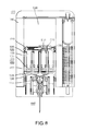
- FIG. 2 is a front view of a system according to an embodiment of the invention.
- FIG. 3 is a side view of a system according to an embodiment of the invention.
- FIG. 4 is a cross-sectional view taken along line A-A of FIG. 3 of a system according to an embodiment of the invention in a first operative position.
- FIG. 5 is a cross-sectional view taken along line A-A of FIG. 3 of a system according to an embodiment of the invention in a second operative position.
- FIG. 6 is a cross-sectional view taken along line A-A of FIG. 3 of a system according to an embodiment of the invention in a third operative position.
- FIG. 7 is a cross-sectional view taken along line A-A of FIG. 3 of a system according to an embodiment of the invention in a fourth operative position.
- FIG. 8 is a cross-sectional view taken along line A-A of FIG. 3 of a system according to an embodiment of the invention in a fifth operative position.
- FIG. 9 is a cross-sectional view taken along line A-A of FIG. 3 of a system according to an embodiment of the invention in a sixth operative position.
- FIG. 10 is a flowchart illustrating a method according to an embodiment of the invention.
- FIG. 11 is a perspective view of a system according to an embodiment of the invention.
- FIG. 12 is a perspective cross-sectional view the system illustrated in FIG. 11 taken along line B-B of FIG. 11 .
- FIG. 13 is a perspective view of an apparatus according to an embodiment of the invention.
- FIG. 14 is a cross-sectional view of a mechanism according to an embodiment of the invention taken along line A-A of FIG. 3 .
- FIGS. 15 and 16 are schematic illustrations of an auto-injector according to an embodiment of the invention in a first configuration and a second configuration, respectively.
- FIG. 17 is a perspective view of an auto-injector according to an embodiment of the invention.
- FIG. 18 is a perspective view of the auto-injector illustrated in FIG. 17 in a first configuration, with at least a portion of the auto-injector illustrated in phantom lines for ease of reference.
- FIG. 19 is a front view of the auto-injector illustrated in FIGS. 17 and 18 in a first configuration.
- FIG. 20 is a perspective view of the auto-injector illustrated in FIG. 17 showing an assembly according to an embodiment of the invention being removed.
- FIG. 21 is a front view of the auto-injector illustrated in FIG. 17 showing a member according to an embodiment of the invention being removed.
- FIG. 22 is an exploded perspective view of a portion of the auto-injector illustrated in FIG. 20 .
- FIG. 23 is a cross-sectional view of a component illustrated in FIG. 21 .
- FIG. 24 is a perspective view of a component illustrated in FIG. 21 .
- FIG. 25 is a perspective view of a member of the auto-injector illustrated in FIG. 21 .
- FIG. 26 is a perspective view of a portion of the auto-injector illustrated in FIGS. 17 and 21 .
- FIG. 27 is a perspective view of a portion of the auto-injector illustrated in FIGS. 17 and 26 .
- FIG. 28 is a partially exploded perspective view of a base of the auto-injector illustrated in FIG. 26 .
- FIG. 29 is an exploded perspective view of a portion of the auto-injector shown in FIG. 21 .
- FIG. 30 is a front view of a component of the auto-injector shown in FIG. 29 .
- FIG. 31 is a front view of the auto-injector illustrated in FIG. 19 in a second configuration.
- FIG. 32 is a perspective view of a portion of the auto-injector shown in FIG. 31 .
- FIGS. 33 and 34 are perspective views of a portion of the auto-injector shown in FIG. 32 .
- FIG. 35 is a top view of the housing of the auto-injector shown in FIG. 31 .
- FIG. 36 is a cross-sectional view of the housing taken along line 36 - 36 in FIG. 35 .
- FIG. 37 is front view of the auto-injector illustrated in FIGS. 19 and 31 in a third configuration.
- FIG. 38 is a front view of the portion of the auto-injector labeled as 38 in FIG. 37 .
- FIG. 39 is a perspective view of a portion of the auto-injector shown in FIG. 37 .
- FIG. 40 is a cross-sectional view of a portion of the auto-injector as shown in FIG. 37 .
- FIG. 41 is a perspective view of a portion of the auto-injector as shown in FIG. 37 .
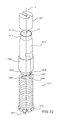
- FIG. 42 is an exploded perspective view of a portion the auto-injector as shown in FIG. 37 .
- FIG. 43 is front view of the auto-injector illustrated in FIGS. 19, 31 and 38 in a fourth configuration.
- FIG. 44 is a front view of a portion of the auto-injector illustrated in FIGS. 19, 31, 38 and 43 in a fifth configuration.
- FIG. 45 is a front view of the auto-injector illustrated in FIGS. 19, 31, 38, 43 and 44 in a sixth configuration.
- FIGS. 46-48 are schematic illustrations of an auto-injector according to an embodiment of the invention in a first configuration, a second configuration and a third configuration, respectively.
- FIGS. 49 and 50 are schematic illustrations of an auto-injector according to an embodiment of the invention in a first configuration and a second configuration, respectively.
- FIGS. 51-53 are schematic illustrations of an auto-injector according to an embodiment of the invention in a first configuration, a second configuration and a third configuration, respectively.
- FIGS. 54 and 55 are schematic illustrations of a portion of an auto-injector according to an embodiment of the invention in a first configuration and a second configuration, respectively.
- FIG. 56 is a schematic illustration of an auto-injector according to an embodiment of the invention in a first configuration.
- FIGS. 57-60 are schematic illustrations of a portion of the auto-injector labeled as 57 - 60 in FIG. 56 in a second configuration, a third configuration, a fourth configuration and a fifth configuration, respectively.
- FIG. 61 is a plot showing the pressure within the auto-injector shown in FIG. 56 as a function of the position of a portion of the auto-injector.
- an apparatus includes a movable member and a valve coupled to the movable member.
- the movable member is configured to be disposed within a housing of a medical device and has a first end portion and second end portion. A portion of the first end portion is configured to define a portion of a boundary of a gas chamber. The first end portion defines an opening configured to be in fluid communication between the gas chamber and an area outside the gas chamber. The second end portion is configured to be coupled to a needle configured to deliver a medicament into a body.
- the valve is configured to selectively allow fluid communication between the gas chamber and the area outside the gas chamber through the opening defined by the first end portion of the movable member.
- an apparatus in some embodiments, includes a movable member, a valve and an actuator.
- the valve and the actuator are each coupled to the movable member.
- the movable member is configured to be disposed within a housing of a medical device and has a first end portion and second end portion. A portion of the first end portion is configured to define a portion of a boundary of a gas chamber. The first end portion defines an opening configured to be in fluid communication between the gas chamber and an area outside the gas chamber.
- the second end portion is configured to be coupled to a needle configured to deliver a medicament into a body.
- the valve is configured to selectively allow fluid communication between the gas chamber and the area outside the gas chamber through the opening defined by the first end portion of the movable member.
- the actuator is configured to move the valve between a first position and a second position.
- the valve When the valve is in the first position the gas chamber is fluidically isolated from the area outside the gas chamber.
- the valve When the valve is in the second position the gas chamber is in fluid communication with the area outside the gas chamber.
- an apparatus in some embodiments, includes a housing, a medicament container, a medicament injector, an injection member and a valve.
- the housing defines a gas chamber.
- the medicament container is configured to be movably disposed within the housing and defines a portion of a boundary of the gas chamber.
- the medicament injector includes a seal configured to engage a portion of the housing to fluidically isolate the gas chamber from an area outside the gas chamber. A portion of the medicament injector is engaged with a medicament container that is movably disposed within the housing.
- the injection member which can be, for example, a needle, defines a lumen configured to be in fluid communication with the medicament container and is configured to convey a medicament from the medicament container into a body of a patient.
- the medicament injector has a first position and a second position.
- the injection member When in the first position, the injection member is contained within the housing. When in the second position, a portion of the injection member extends from the housing.
- the valve which can be disposed on the medicament injector, has a first configuration and a second configuration. When the valve is in the first configuration, the gas chamber is fluidically isolated from the area outside the gas chamber. When the valve is in the second configuration, the gas chamber is in fluid communication with the area outside the gas chamber.
- an apparatus in some embodiments, includes a housing defining a gas chamber, a movable member and a gas release assembly.
- the movable member has a first portion and a second portion.
- the first portion defines a portion of a boundary of the gas chamber.
- the second portion is configured to be coupled to a needle that can deliver a medicament into a body.
- the movable member is disposable within the housing in a first position and a second position. When the movable member is in the first position, the needle is disposed within the housing. When the movable member is in the second position, a portion of the needle extends outside the housing.
- the gas release assembly which can include, for example, a valve, an actuator and a passageway between the gas chamber and an area outside of the gas chamber, has a first configuration and a second configuration.
- the gas release system When the gas release system is in its first configuration, the gas chamber is fluidically isolated from the area outside the gas chamber.
- the gas release system When the gas release system is in its second configuration, the gas chamber is in fluid communication with the area outside the gas chamber.
- the gas release assembly is configured to be moved from its first configuration to its second configuration when the movable member is in its second position.
- the gas release system is further configured to be maintained in its second configuration independent of the position of the movable member.
- an apparatus in some embodiments, includes a housing defining a gas chamber, a movable member and a valve.
- the movable member is configured to move longitudinally within the housing.
- the movable member has a first portion and a second portion.
- the first portion defines a portion of a boundary of the gas chamber.
- the second portion is configured to move a plunger within a medicament container to expel a medicament contained within the medicament container.
- the valve defines a flow passageway between the gas chamber and an area outside the gas chamber.
- the flow passageway has a flow area that varies as a function of a longitudinal position of the movable member.
- FIG. 1 is a perspective view
- FIG. 2 is a front view
- FIG. 3 is a side view, of a system 1000 according to the invention, which can comprise a housing 1100 , which, in some embodiments, can comprise a handheld portion 1800 separated via an actuation guard 1200 from an actuation bar 1300 .
- Actuation guard 1200 can prevent accidental activation of system 1000 .
- Housing 1100 can be constructed of a durable material, such as stainless steel, aluminum, polycarbonate, etc., to protect a compressed gas container, medicament, injection apparatus and/or user of system 1000 .
- the injection apparatus can be actuated by a fluid pressure, such as pressure provided by the compressed gas, which upon completion of actuation can escape housing 1100 via gas escape opening, such as via status indicator 1400 .
- a status of a system 1000 can be determined via status indicator 1400 , which can provide a view, such as via a UV blocking, photo-sensitive, and/or translucent window, into an interior of housing 1100 . Viewable through the window can be a status of medicament carried by housing 1100 , a location of a needle and/or injection apparatus for the medicament, and/or an activation status of system 1000 . For example, if the medicament has aged to the point of discoloration, which aging might or might not render the medication useless, harmful, etc., status indicator 1400 can allow that situation to be determined.
- gas can escape housing 1100 via status indicator 1400 and/or another opening in housing 1100 .
- system 1000 can provide a compact medicament delivery mechanism that can efficiently and/or rapidly deliver a prescribed dose.
- the length (L) and width (W) of system 1000 can be similar to that of a credit card, and the thickness (T) can be less than one inch.
- some embodiments of system 1000 can provide a conveniently carried, easy-to-use, easy to activate drug delivery apparatus that can require little to no training to safely carry, use, and/or dispose of.
- system 1000 and/or housing 1100 can provide various tactile clues.
- a top 1110 of housing 1100 can be rounded, and a bottom 1120 of actuation bar 1300 of housing 1100 can be flat.
- Other tactile clues are also possible, such as bulges, ribs, grooves, gaps, roughened surfaces, indentations, etc.
- FIG. 4 is a cross-sectional view taken along line A-A of FIG. 3 of an embodiment of a system 1000 in a first operative position.
- FIGS. 5, 6, 7, 8, and 9 show system 1000 of FIG. 4 in second, third, fourth, fifth, and sixth operative positions, respectively.
- System 1000 can comprise a housing 1100 , handheld portion 1800 , actuation guard 1200 , and/or actuation bar 1300 .
- System 1000 can comprise system actuator 2000 , gas reservoirs 3000 , medicament actuator 4000 , medicament storage assembly 5000 , medicament carrier 9000 , needle assembly 6000 , use indicator 7000 , and/or gas vent mechanism 8000 , etc.
- system actuator 2000 can be adapted to rapidly discharge an actuating portion of a contents of a compress gas container.
- system actuator 2000 can comprise a compressed gas container 2400 , which initially can contain a compressed gas 2500 , an actuating portion of which can be released from container 2400 by penetration of a gas port 2600 via a point of a puncturer 2700 .
- actuation bar 1300 can be moved closer to and/or in contact with handheld portion 1800 .
- gas container 2400 can be brought into contact with puncturer 2700 via extension of a pre-compressed spring 2300 and/or movement of an actuation stick 2200 .
- actuation guard 1200 can prevent accidental activation of system 1000 and/or unintended discharge of an actuating portion of the contents 2500 of gas container 2400 .
- an actuating portion of compressed gas 2500 can escape from container 2400 and flow via gas reservoirs 3000 , such as gas channel 3100 .
- the flowing gas can meet and/or apply gas pressure to medicament actuator 4000 , which can comprise a pusher 4100 , which can travel within a sleeve 1500 defined by walls 1520 .
- Sleeve 1500 can be constructed of metal, stainless steel, aluminum, plastic, polycarbonate, etc.
- Seals 4200 such as o-rings, can resist gas leakage, such as past pusher 4100 and/or out of housing 1100 .
- pusher 4100 can function as a piston traveling within a cylinder, although it is not necessarily required that the cross-sectional shape of sleeve 1500 be round.
- medicament actuator 4000 can interface with medicament storage assembly 5000 .
- medicament actuator 4000 can comprise a plurality of plungers 4300 , each of which can be capped with a piston 4400 which can sealingly slide and/or move within a corresponding vial 5100 containing a liquid medicament 5200 .
- pusher 4100 in response to pressure applied by an actuating portion of the contents 2500 of compressed gas container 2400 , pusher 4100 can cause plungers 4300 and/or pistons 4400 to simultaneously move.
- the number of corresponding sets of plungers 4300 , pistons 4400 , and/or vials 5100 can be 2, 3, 4, 5, 6, or more.
- Pistons 4400 can be constructed of a resilient, durable, and/or sealing material, such as a rubber.
- Each plunger 4300 from the plurality of plungers can define a longitudinal axis, the longitudinal axes (e.g., axes 4310 , 4320 , 4330 , 4340 ) of the plurality of plungers can be parallel, non-coaxial, and/or co-planar.
- Each vial 5100 from the plurality of vials can be substantially cylindrical with a substantially round and/or substantially elliptical cross-sectional shape.
- each vial 5100 can define a longitudinal axis, the longitudinal axes of the plurality of vials can be parallel, non-coaxial, and/or co-planar.
- the longitudinal axis of each vial can be co-axial with the longitudinal axis of its corresponding plunger.
- Each vial can be capped at one end with a frangible seal 5300 , which can be burst when piston 4400 generates sufficient pressure upon medicament 5200 , thereby allowing at least a portion of medicament 5200 to flow out of vial 5100 and into medicament carrier 9000 .
- the plurality of vials can be fluidly coupleable to the actuating portion of the contents 2500 of gas container 2400 .
- Medicament carrier 9000 can hold each of vials 5100 and can travel within sleeve 1500 .
- Medicament carrier 9000 can comprise a plurality of channels 9200 adapted to receive medicament 5200 as it exits its respective vial 5100 , and direct medicament 5200 to a common conduit 9300 .
- Medicament carrier 9000 can interface with needle assembly 6000 and/or use indicator 7000 .
- medicament 5200 can enter needle assembly 6000 , such as into a single needle 6100 via which medicament can approach needle tip 6200 .
- medicament actuator 4000 and/or medicament carrier 9000 are driven toward actuator bar 1300 , needle tip 6200 can penetrate an end 6400 of needle sheath 6300 and exit actuator bar 1300 at needle port 1340 .
- sheath seat 1330 can come in contact with sheath tip 6400 , thereby causing sheath 6300 to buckle and/or crumble.
- bar stop 1320 can approach medicament carrier stop 9400 , while carrier spring 1600 is compressed.
- needle tip 6200 can extend further from actuator bar 1300 and sheath 6300 can become further compressed and/or deformed.
- needle tip 6200 can extend from housing 1100 from approximately 0.25 millimeters to approximately 20 millimeters, including all values and subranges therebetween, such as up to approximately 2 millimeters, greater than approximately 5 millimeters, from approximately 5.13 millimeters to approximately 9.98 millimeters, etc.
- medicament carrier 9000 can be driven until medicament carrier stop 9400 contacts actuator bar stop 1300 thereby resisting further travel of medicament carrier 9000 .
- additional expansion of gas chamber 3200 can cause medicament actuator 4000 , pusher 4100 , plungers 4300 , and/or pistons 4400 to initiate travel with respect to medicament storage assembly 5000 , thereby generating an expulsion pressure in vials 5100 , and/or thereby rupturing frangible seals 5300 and allowing medicament 5200 to enter medicament carrier 9000 , and begin flowing through medicament channels 9200 , medicament conduit 9300 , needle 6100 , and/or out needle tip 6200 and into a patient.
- frangible seals 5300 can be replaced and/or augmented by a frangible seal located at or near where medicament conduit 9300 couples to needle 6100 .
- Frangible seals 5300 can be constructed of a thin, taught, resilient, durable, and/or sealing material potentially having a predetermined yield strength, such as a rubber, such as chromo butyl rubber, and/or of a relatively brittle material potentially having a predetermined yield strength, such as ceramic, certain plastics, such as polystyrene, etc.
- medicament carrier hooks 9600 can engage with engagement receivers 7100 in use indicator 7000 .
- medicament actuator 4000 , pusher 4100 , plungers 4300 , and/or pistons 4400 can continue moving until they complete their travel within medicament storage assembly 5000 , thereby expelling a predetermined dose of medicament 5200 from vials 5100 , out of needle assembly 6000 , external to housing 1100 , and/or into the patient.
- medicament actuator 4000 , pusher 4100 , plungers 4300 , and/or pistons 4400 can continue moving until they complete their travel with respect to medicament carrier 9000 , thereby causing gas release actuator 9700 to engage with gas relief valve 8200 .
- Engagement of gas release actuator 9700 with gas relief valve 8200 can cause gas within gas chamber 3200 to exit gas chamber 3200 , discharge away from pistons 4400 , and/or exhaust from system 1000 and/or housing 1100 , such as via status indicator 1400 and/or a gas escape port located on housing 1100 ).
- the pressure applied by the gas in gas chamber 3200 can decrease until the force applied by the gas on medicament actuator 4000 is less than the force of compressed spring 1600 .
- spring(s) 1600 can begin to expand, thereby moving medicament carrier 9000 , vial assembly 5000 , and medicament actuator 4000 away from actuator bar 1300 and helping to exhaust gas from gas chamber 3200 .
- use indicator 7000 can travel with it, due to the engaged relationship of medicament carrier hooks 9600 and engagement receivers 7100 and/or engagement catches 7200 in use indicator 7000 .
- sheath 6300 can travel with it, thereby creating a gap between sheath tip 6400 and needle port 1340 , and thereby exposing a previously non-visible colored portion 1350 of actuation bar 1300 and/or providing an indication that system 1000 has been used (and likely substantially exhausted of its medicament), thereby discouraging any further attempts to use system 1000 .
- needle 6100 can retract into sheath 6300 which un-buckles and/or un-deforms towards its original shape. Eventually, needle 6100 can retract completely within the boundaries of housing 1100 , thereby tending to prevent accidental needle sticks after the initial injection and/or potentially reducing and/or eliminating a sharps hazard.
- system actuator 2000 can comprise a finger triggered, twistable, pivotable, and/or lever-operated mechanism.
- system actuator 2000 can comprise a twistable handle that can screw into gas port 2600 .
- system actuator 2000 can be a finger trigger located on a side of the housing.
- FIG. 10 is a flowchart of an embodiment of a method 10000 for operating a medicament delivery apparatus.
- an actuation lock for the apparatus is released.
- an actuating portion of the contents of a compressed gas container are released.
- a needle is extended from the apparatus.
- a piston applies pressure to a medicament stored in one of a plurality of vials.
- a frangible seal containing the medicament in the vial is burst.
- the medicament flows from the vial, through the needle, and into a patient.
- the needle is withdrawn from the patient and/or retracted into the pre-use bounds of the apparatus.
- the apparatus is rendered unusable for additional injections and/or indicated as previously utilized.
- FIG. 11 is a perspective view of an embodiment of system 1000 , showing actuation guard 1200 removed from housing 1100 , so that actuation guard 1200 no longer separates actuator bar 1300 from handheld portion 1800 .
- Actuation guard 1200 can comprise a grippable portion 1220 that can be gripped by a user to pull actuation guard 1200 away from housing 1100 , thereby allowing system 1000 to be activated, such as via slapping actuator bar 1300 against a thigh of the user.
- Actuation guard 1200 can comprise an actuation stick separator portion 1240 , that can keep separate actuation stick prongs 2240 when actuation guard 1200 is installed on housing 1100 .
- Actuation guard 1200 can comprise a guard portion 1260 that can separate actuator bar 1300 from handheld portion 1800 when system 1000 is not in use and/or when system 1000 has not been used.
- FIG. 12 is a perspective cross-sectional view taken along line B-B of FIG. 11
- FIG. 13 is a perspective view of an embodiment of actuation stick 2200
- system 1000 can comprise housing 1100 , actuation bar 1300 , and system actuator 2000 , which can comprise prong squeezer 1390 , actuation stick 2200 , prong retainer 2100 , spring 2300 , upper spring retainer 2260 , gas container 2400 , gas port 2600 , and/or puncturer 2700 .
- prong squeezer 1390 can urge prong tips 2220 of prongs 2240 of actuation stick 2200 toward one another.
- prong tips 2200 can have a triangular, wedge, angular, and/or frusto-conical shape. As prongs tips 2220 slide along the angled V-groove of prong squeezer 1390 , prong catches 2230 can substantially lose contact with prong retainer 2100 .
- FIG. 14 is a cross-sectional view of an embodiment of gas venting mechanism 8000 of system 1000 taken along line A-A of FIG. 3 .
- System 1000 can comprise handheld portion 1800 , actuator bar 1300 , sleeve 1500 .
- medicament 5200 can be expelled along medicament path 5900 , which can extend past frangible seal 5300 , through medicament channels 9200 , medicament conduit 9300 , and needle 6100 , and into the body of a user, such as subcutaneously, intramuscularly, and/or at a depth of from approximately 0.25 millimeters to approximately 20 millimeters, including all values and subranges therebetween, such as up to 2 millimeters, greater than 5 millimeters, etc.
- gas release actuator 9700 As pistons 4440 near the limit of their travels, engagement of gas release actuator 9700 with gas relief valve 8200 can cause compressed spring 8300 to move valve arm such that o-ring 8400 is urged away from its seat 8500 . This movement can reveal a passage 8600 , via which gas can exit gas chamber 3200 along gas exhaust path 8900 , which can extend between sleeve inner walls 1520 and outer walls 9100 of medicament carrier 9000 . Eventually, gas exhaust path 8900 can extend between handheld portion 1800 and actuator bar 1300 .
- valve 8200 made of rubber or any other resilient material, can be placed across seat 8500 to provide a seal that, once gas release actuator 9700 interacts with valve 8200 , allows valve 8200 to bend or flap upwards away from seat 8500 , causing the gas to escape via passage 8600 .
- FIGS. 15 and 16 are schematic illustrations of an auto-injector 2002 according to an embodiment of the invention in a first configuration and a second configuration, respectively.
- the auto-injector 2002 includes a housing 2110 , a medicament container 2262 , a movable member 2312 , a gas relief valve 2328 and a compressed gas source 2412 .
- the medicament container 2262 which can be, for example, a pre-filled cartridge, a vial, an ampule or the like, is fixedly disposed within the housing 2110 and defines a longitudinal axis Lm.
- the medicament container 2262 contains a medicament 2268 , such as, for example, epinephrine.
- the movable member 2312 includes a proximal end portion 2316 and a distal end portion 2318 .
- the proximal end portion 2316 includes a surface 2322 that, together with the housing 2110 , defines a gas chamber 2120 . Said another way, the surface 2322 defines a portion of a boundary of the gas chamber 2120 .
- the proximal end portion 2316 defines an opening 2326 therethrough, which is in fluid communication between the gas chamber 2120 and an area outside of the gas chamber 2128 .
- the distal end portion 2318 is movably disposed within the medicament container 2262 along the longitudinal axis Lm, as shown by the arrow A.
- a needle 2212 is coupled to the distal end 2318 of the movable member 2312 .
- the needle 2212 defines a lumen (not shown) and a side opening 2215 .
- the gas relief valve 2328 is coupled to the movable member 2312 such that it can selectively allow fluid communication between the gas chamber 2120 and the area outside of the gas chamber 2128 .
- the gas relief valve 2328 can include, for example, a movable membrane, a frangible seal, a spring-loaded gas relief valve body or the like.
- the gas chamber 2120 is placed in fluid communication with the compressed gas source 2412 , thereby allowing a pressurized gas to flow into the gas chamber 2120 .
- the movable member 2312 moves within the housing 2110 and the medicament container 2262 , as indicated by arrow A.
- the needle 2212 is extended through the housing 2110 .
- the movement of the movable member 2312 also forces the medicament 2268 through the side opening 2215 and into the lumen (not shown) defined by the needle 2212 . In this manner, the medicament injection occurs while the needle 2212 is being extended from the housing 2110 (i.e., while the needle 2212 is being inserted into the body).
- the pressure of the pressurized gas within the gas chamber 2120 can be controlled by the gas relief valve 2328 .
- the gas relief valve 2328 is actuated as indicated by the arrow B, thereby allowing pressurized gas to flow from the gas chamber 2120 to the area outside of the gas chamber 2128 through the opening 2326 , as shown by the arrows g.
- the gas relief valve 2328 is shown as being actuated after substantially all of the medicament 2268 has been injected, in other embodiments, the gas relief valve 2328 can be actuated at any time during the injection event.
- the gas relief valve 2328 can be actuated as the injection event is beginning to control the rate of needle insertion and/or medicament injection.
- the gas relief valve 2328 can be actuated at the end of the injection event to allow the needle 2212 to be retracted to a position within the housing 2110 . In yet other embodiments, the gas relief valve 2328 can be actuated upon completion of the injection event to prevent residual gas from undesirably building up within the gas chamber 2120 .
- FIG. 17 is a perspective view of an auto-injector 3002 according to an embodiment of the invention in a first configuration.
- the auto-injector 3002 includes a housing 3110 having a proximal end portion 3112 and a distal end portion 3114 .
- the distal end portion 3114 of the housing 3110 includes a protrusion 3142 to help a user grasp and retain the housing 3110 when using the auto-injector 3002 .
- the protrusion 3142 is configured to prevent the auto-injector 3002 from slipping from the user's grasp during use.
- a base 3520 is movably coupled to the distal end portion 3114 of the housing 3110 .
- a needle guard assembly 3810 is removably coupled to the base 3520 .
- a safety lock 3710 is removably coupled to the base 3520 .
- the distal end portion 3114 of the housing is oriented towards the user such that the base 3520 is in contact with the portion of the body where the injection is to be made.
- the base 3520 is then moved towards the proximal end 3112 of the housing 3110 to actuate the auto-injector 3002 .
- the housing 3110 also includes a transparent status window 3118 (see FIG. 36 ) to allow a user to determine the status of the auto-injector 3002 or the medicament contained therein.
- FIG. 18 is a perspective view of the auto-injector 3002 showing the housing 3110 in phantom lines so that the components contained within the housing 3110 can be more clearly seen.
- FIG. 18 shows the auto-injector 3002 without the needle guard assembly 3810 and the safety lock 3710 .
- FIG. 19 is a front view of the auto-injector 3002 showing the housing 3110 in phantom lines.
- the auto-injector 3002 includes a medicament injector 3210 and a movable member 3312 engaged with the medicament injector 3210 , each of which are disposed within the housing 3110 .
- the auto-injector 3002 also includes a system actuator 3510 , a compressed gas container 3412 and a gas release mechanism 3612 .
- the medicament injector 3210 includes a carrier 3250 that is movable within the housing 3110 , a medicament container 3262 and a needle 3212 .
- the medicament container 3262 is coupled to the carrier 3250 .
- the needle 3212 is disposed within a needle hub portion 3223 (see FIG. 22 ) of the carrier to allow the needle 3212 to be placed in fluid communication with the medicament container 3262 during an injection event.
- the movable member 3312 includes a proximal end portion 3316 and a distal end portion 3318 .
- the proximal end portion 3316 includes a surface 3322 that, together with the housing 3110 , defines a gas chamber 3120 . Said another way, the surface 3322 defines a portion of a boundary of the gas chamber 3120 .
- the distal end portion 3318 is disposed within the medicament container 3262 . In use, the movable member 3312 moves towards the distal end portion 3114 of the housing 3110 , as indicated by arrow C, in response to a force produced by a pressurized gas on the surface 3322 of the movable member 3312 .
- the movable member 3312 and the medicament injector 3250 are moved towards the distal end portion 3114 of the housing 3110 , thereby exposing the needle 3212 from the housing 3110 .
- the movable member 3312 then continues to move within the medicament container 3262 to expel a medicament from the medicament container 3262 through the needle 3212 .
- the auto-injector 3002 is actuated by the system actuator 3510 , which is configured to move the compressed gas container 3412 into contact with the gas release mechanism 3612 .
- the gas release mechanism 3612 punctures a portion of the compressed gas container 3412 to release the pressurized gas contained therein into the gas chamber 3120 defined by the housing 3110 .
- the system actuator 3510 includes a rod 3540 , a spring 3560 and a spring retainer 3570 .
- the rod 3540 has a proximal end portion 3542 and a distal end portion 3544 .
- the proximal end portion 3542 of the rod 3540 is coupled to the compressed gas container 3412 .
- the distal end portion 3544 of the rod 3540 is coupled to the spring retainer 3570 by two projections 3548 , which can be moved inwardly towards each other to decouple the rod 3540 from the spring retainer 3570 , as discussed below.
- the spring 3560 is disposed about the rod 3540 in a compressed state such that the spring 3560 is retained by the proximal end portion 3542 of the rod 3540 and the spring retainer 3570 .
- the rod 3540 is spring-loaded such that when the distal end portion 3544 of the rod 3540 is decoupled from the spring retainer 3570 , the force of the spring 3560 causes the rod 3540 , and therefore the compressed gas container 3412 , to move proximally as indicated by arrow D and into contact with the gas release mechanism 3612 .
- the base 3520 defines an opening 3522 configured to receive a portion of the projections 3548 when the base is moved towards the proximal end 3112 of the housing 3110 , as indicated by arrow E.
- the projections 3548 are received within the opening 3522 , they are moved together causing the distal end portion 3544 of the rod 3540 to be released from the spring retainer 3570 .
- the medicament injector 3210 defines a longitudinal axis Lm that is non-coaxial with the longitudinal axis Le defined by the compressed gas container 3412 . Accordingly, the medicament injector 3210 , the compressed gas container 3412 and the system actuator 3510 are arranged within the housing 3110 such that the housing has a substantially rectangular shape. Moreover, the non-coaxial relationship between the medicament injector 3210 and the compressed gas container 3412 allows the auto-injector 3002 to be actuated by manipulating the base 3520 , which is located at the distal end portion 3114 of the housing 3110 .
- the use and actuation of the auto-injector 3002 includes several discrete operations.
- the auto-injector 3002 is enabled by removing the needle guard 3810 and the safety lock 3710 (see FIGS. 20 and 21 ).
- the auto-injector 3002 is actuated by moving the base 3520 proximally towards the housing 3110 .
- the compressed gas container 3412 engages the gas release mechanism 3612 , which causes the pressurized gas to be released into the gas chamber 3120 (see FIG. 31 ).
- the pressurized gas produces a force that causes the movable member 3312 and the medicament injector 3210 to move distally within the housing 3110 (see FIG. 37 ).
- the movement of the medicament injector 3210 causes the needle 3212 to extend from distal end portion 3114 of the housing 3110 and the base 3520 .
- This operation can be referred to as the “needle insertion” operation.
- the movable member 3312 continues to move the medicament container 3262 distally within the carrier 3250 .
- the continued movement of the medicament container 3262 places the needle 3212 in fluid communication with the medicament container 3262 , thereby allowing the medicament to be injected (see FIG. 43 ).
- the force from the pressurized gas causes the movable member 3312 to move within the medicament container 3262 , thereby expelling the medicament through the needle 3212 (see FIG.
- This operation can be referred to as the “injection operation.” Seventh, upon completion of the injection, the pressurized gas is released from the gas chamber 3120 , thereby allowing the medicament injector 3210 and the movable member 3312 to be moved proximally within the housing. This operation can be referred to as the “retraction operation” (see FIG. 45 ). A detailed description of the components contained in the auto-injector 3002 and how they cooperate to perform each of these operations is discussed below.
- the auto-injector 3002 Prior to use, the auto-injector 3002 must first be enabled by first removing the needle guard 3810 and then removing the safety lock 3710 . As illustrated by arrow G in FIG. 20 , the needle guard 3810 is removed by pulling it distally. Similarly, as illustrated by arrow H in FIG. 21 , the safety lock 3710 is removed by pulling it substantially normal to the longitudinal axis Le of the compressed gas container 3412 . Said another way, the safety lock 3710 is removed by moving it in a direction substantially normal to the direction that the needle guard 3810 is moved. As described in more detail herein, the needle guard 3810 and the safety lock 3710 are cooperatively arranged to prevent the safety lock 3710 from being removed before the needle guard 3810 has been removed. Such an arrangement prevents the auto-injector 3002 from being actuated while the needle guard 3810 is in place.
- the needle guard 3810 includes a sheath 3820 and a sheath retainer 3840 .
- the sheath 3820 has a proximal end portion 3822 and a distal end portion 3824 and defines an opening 3826 configured to receive a portion of the needle 3212 when the needle guard 3810 is in a first (or installed) position.
- the sheath 3820 further defines a recessed portion 3828 within the opening 3826 that engages a corresponding protrusion 3238 defined by an outer surface 3236 of the needle hub 3223 . In this manner, when the needle guard 3810 is in its first position, the sheath 3820 is removably coupled to the needle hub 3223 .
- the recessed portion 3828 and the protrusion 3238 form a seal that is resistant to microbial penetration.
- the sheath retainer 3840 has a proximal portion 3842 and a distal portion 3844 .
- the proximal portion 3842 of the sheath retainer 3840 includes a protrusion 3856 that engages a corresponding recess 3526 in the base 3520 (see FIG. 28 ) to removably couple the sheath retainer 3840 to the base 3520 .
- the distal portion 3844 of the sheath retainer 3840 defines an opening 3846 through which the distal end portion 3824 of the sheath 3820 is disposed.
- the distal portion 3844 of the sheath retainer 3840 includes a series of retaining tabs 3852 that engage the distal end portion 3824 of the sheath 3820 to couple the sheath 3820 to the sheath retainer 3840 .
- the sheath retainer 3840 is moved distally away from the base 3520 into a second (or removed) position, as shown in FIG. 20 , the sheath 3820 is removed from the needle 3412 .
- this arrangement allows the sheath 3820 to be disposed about the needle 3412 independently from when the sheath retainer 3840 is coupled to the sheath 3820 .
- the distal portion 3844 of the sheath retainer 3840 also includes a protrusion 3848 to aid the user when grasping the needle guard 3810 .
- the sheath retainer 3840 When the needle guard 3810 is in its first position, the sheath retainer 3840 is disposed within a recess 3720 defined by one of the extended portions 3716 of the safety lock 3710 (see FIG. 25 ). This arrangement prevents the safety lock 3710 from being removed when the needle guard 3810 is in its first position, which in turn, prevents the auto-injector 3002 from being actuated when the needle guard 3810 is in its first position.
- the outer surface of the sheath retainer 3840 includes an indicia 3850 to instruct the user in operating the auto-injector 3002 .
- the indicia 3850 includes a numeral to indicate the order of operation and an arrow to indicate the direction in which the needle guard 3810 should be moved.
- the indicia 3850 can include different colors, detailed instructions or any other suitable indicia to instruct the user.
- the indicia 3850 can protrude from the sheath retainer 3840 to aid the user when grasping the needle guard 3810 .
- the sheath 3820 can be constructed from any suitable material, such as, for example polypropylene, rubber or any other elastomer. In some embodiments, the sheath 3820 can be constructed from a rigid material to reduce the likelihood of needle sticks during the manufacturing process. In other embodiments, the sheath 3820 can be constructed from a flexible material.
- the safety lock 3710 is a U-shaped member having a first end 3712 and a second end 3714 .
- the second end 3714 of the safety lock 3710 includes two extended portions 3716 , each of which includes an inwardly facing protrusion 3718 .
- the extended portions 3716 extend around a portion of the base 3520 to space the base 3520 apart from the distal end portion 3114 of the housing 3110 .
- the protrusions 3718 are configured engage a portion of the base 3520 to removably couple the safety lock 3710 in its first position.
- One of the extended portions 3716 defines a recess 3720 that receives the sheath retainer 3840 when the needle guard 3810 is in its first position, as discussed above.
- both extended portions 3716 can include a recess 3720 to receive the sheath retainer 3840 .
- the safety lock 3710 can be engaged with the needle guard 3810 to prevent movement of the safety lock 3710 when the needle guard 3810 is in place in any suitable manner.
- the sheath retainer can include protrusions that are received within corresponding openings defined by the safety lock.
- the safety lock can include protrusions that are received within corresponding openings defined by the sheath retainer.
- the first end 3712 of the safety lock 3710 includes a locking protrusion 3722 that extends inwardly. As shown in FIG. 26 , when the safety lock 3710 is in its first position, the locking protrusion 3722 extends between the projections 3548 of the rod 3540 and obstructs the opening 3522 of the base 3520 . In this manner, when the safety lock 3710 is in its first position, the base 3520 cannot be moved proximally to allow the projections 3548 to be received within the opening 3522 . The arrangement of the locking protrusion 3722 also prevents the projections 3548 from being moved inwardly towards each other. Accordingly, when the safety lock 3710 is in its first position, the auto-injector 3002 cannot be actuated.
- the outer surface 3724 of the first end 3712 of the safety lock 3710 includes a series of ridges 3726 to allow the user to more easily grip the safety lock 3710 .
- the outer surface 3724 of the first end 3712 of the safety lock 3710 also includes an indicia 3728 to instruct the user in operating the auto-injector 3002 .
- the indicia 3728 includes a numeral to indicate the order of operation and an arrow to indicate the direction in which the safety lock 3710 should be moved.
- the indicia 3728 can include different colors, detailed instructions or any other suitable indicia to instruct the user.
- the indicia 3728 can protrude from the safety lock 3710 to aid the user when grasping the safety lock 3710 .
- the auto-injector 3002 can then be actuated by moving the base 3520 proximally towards the housing 3110 , as indicated by arrow I in FIG. 27 .
- the base 3520 defines two openings 3536 that receive corresponding attachment protrusions 3150 disposed on the distal end portion 3114 of the housing 3110 . In this manner, the movement and/or alignment of the base 3520 relative to the housing 3110 is guided by the attachment protrusions 3150 and the openings 3536 (see FIG. 36 ).
- Each attachment protrusion 3150 is secured within its corresponding opening 3536 by a lock washer 3534 .
- the lock washers 3534 each define an opening 3535 that receives a portion of the attachment protrusion 3150 .
- the lock washers 3534 are disposed within slots 3533 defined by the base 3520 so that the openings 3535 are aligned with the attachment protrusions 3150 .
- the openings 3535 are configured to allow the lock washers 3534 to move proximally relative to the attachment protrusions 3150 , but to prevent movement of the lock washers 3534 distally relative to the attachment protrusions 3150 .
- the base 3520 becomes fixedly coupled to the housing 3110 .
- the lock washers 3534 prevent the base 3520 from returning to its initial position. Said another way, the arrangement of the lock washers 3534 prevents the base 3520 from being “kicked back” after the auto-injector 3002 has been actuated.
- the base 3520 also defines a needle opening 3532 , a recess 3526 and two retraction spring pockets 3531 .
- the needle opening 3532 receives a portion of the needle guard 3810 when the needle guard is in its first position. Additionally, when the auto-injector is in its third configuration (see FIG. 37 ), the needle 3212 extends through the needle opening 3532 .
- the recess 3526 receives the corresponding protrusion 3856 on the sheath retainer 3840 to removably couple the needle guard 3810 to the base 3520 .
- the retraction spring pockets 3531 receive a portion of the retraction springs 3350 .
- the base 3520 includes two opposing tapered surfaces 3524 that define an opening 3522 configured to receive a corresponding tapered surface 3550 of the projections 3548 when the base is moved proximally towards the housing 3110 .
- the projections 3548 are received within the tapered opening 3522 , they are moved together as indicated by arrows J in FIG. 27 .
- the inward movement of the projections 3548 causes the rod 3540 to become disengaged from the spring retainer 3570 , thereby allowing the rod 3540 to be moved proximally along its longitudinal axis as the spring 3560 expands.
- FIGS. 29 and 30 A more detailed description of the components included in the system actuator 3510 is provided below with reference to FIGS. 29 and 30 .
- the system actuator 3510 includes a rod 3540 , a spring 3560 disposed about the rod 3540 and a spring retainer 3570 .
- the spring retainer 3570 retains both the spring 3560 and the rod 3540 .
- the spring retainer 3570 includes a first surface 3572 , a second surface 3574 and a series of outwardly extending engagement tabs 3576 .
- the spring retainer 3570 is disposed within the gas container opening 3124 defined by the housing 3110 (see FIG. 36 ) such that the engagement tabs 3576 engage the interior surface 3123 of the housing 3110 to produce an interference fit. In this manner, the spring retainer 3570 is fixedly disposed within the housing 3110 .
- the rod 3540 has a proximal end portion 3542 and a distal end portion 3544 .
- the distal end portion 3544 of the rod 3540 includes two extensions 3552 disposed apart from each other to define an opening 3554 therebetween.
- Each extension 3552 includes a projection 3548 having a tapered surface 3550 and an engagement surface 3549 .
- the engagement surfaces 3549 engage the second surface 3574 of the spring retainer 3570 to prevent the rod 3540 from moving proximally along its longitudinal axis.
- the tapered surfaces 3550 of the projections 3548 cooperate with the corresponding tapered surfaces 3524 of the base 3520 to move the extensions 3552 inwardly towards each other.
- the inward motion of the extensions 3552 causes the engagement surfaces 3549 to become disengaged from the second surface 3574 of the spring retainer 3570 , thereby allowing the rod 3540 to move between its first position to a second (or actuated) position.
- the proximal end portion 3542 of the rod 3540 includes a retention portion 3545 having a first surface 3547 and a second surface 3546 .
- the first surface 3547 of the retention portion 3545 engages the distal portion 3416 of the compressed gas container 3412 .
- the second surface 3546 of the retention portion 3545 engages a proximal end 3562 of the spring 3560 .
- the first surface 3572 of the spring retainer 3570 engages a distal end 3564 of the spring 3560 .
- the proximal end portion 3542 of the rod 3540 is coupled to the compressed gas container 3412 by a connector 3580 , which is secured to the distal end portion 3416 of the compressed gas container 3412 by a securing member 3588 .
- the connector 3580 includes a proximal end portion 3582 and a distal end portion 3584 .
- the distal end portion 3584 of the connector 3580 is disposed within the opening 3554 defined between the extensions 3552 . In this manner, the connector 3580 is retained by the proximal end portion 3542 of the rod 3540 .
- the distal end portion 3584 of the connector 3580 includes locking tabs 3587 .
- the proximal end portion 3582 of the connector 3580 includes engagement portions 3586 that engage the distal end portion 3416 of the compressed gas container 3412 .
- the engagement portions 3586 are coupled to the compressed gas container 3412 by the securing member 3588 , which can be, for example, a shrink wrap, an elastic band or the like. In other embodiments, the engagement portions 3586 can produce an interference fit with the compressed gas container 3412 , thereby eliminating the need for a securing member 3588 .
- FIG. 31 shows the auto-injector in a second configuration, in which the compressed gas container 3412 is engaged with the gas release mechanism 3612 .
- the compressed gas contained within the compressed gas container 3412 is released to actuate the medicament injector 3210 .
- FIGS. 32 through 36 A more detailed description of the gas release process is provided below with reference to FIGS. 32 through 36 .
- FIG. 32 shows an exploded view of the system actuator 3510 , the compressed gas container 3412 and the gas release mechanism 3612 , each of which are disposed within the gas container opening 3124 defined by the housing 3110 (see FIG. 36 ).
- the compressed gas container 3412 , the system actuator 3510 and the gas release mechanism 3612 are arranged substantially coaxial with each other.
- the compressed gas container 3412 is moved proximally within the gas container opening 3124 defined by the housing 3110 , as indicated by the arrow K in FIG. 32 , until the proximal end 3414 of the compressed gas container 3412 engages the gas release mechanism 3612 .
- the gas release mechanism 3612 includes a cap 3630 and a puncturing element 3620 coupled to and disposed within the cap 3630 .
- the puncturing element has a proximal end 3622 and a distal end 3624 .
- the distal end 3624 of the puncturing element 3620 defines a sharp point 3626 configured to puncture the proximal end 3414 of the compressed gas container 3412 .
- the puncturing element 3620 defines an opening 3627 extending from its distal end 3624 to its proximal end 3622 .
- the cap 3630 has a proximal end 3632 , an outer surface 3635 and an inner surface 3636 .
- the inner surface 3636 of the cap 3630 defines an opening 3634 that receives the proximal end 3414 of the compressed gas container 3412 when the auto-injector 3002 is in its second configuration.
- the proximal end 3632 of the cap 3630 defines an opening 3638 therethrough and a channel 3640 in fluid communication with the opening 3638 .
- the opening 3638 receives the proximal end 3622 of the puncturing element 3620 to couple the puncturing element 3620 to the cap 3630 .
- the puncturing element 3620 is disposed within the cap 3630 such that when the compressed gas container 3412 is moved into the opening 3634 , the distal end 3624 of the puncturing element 3620 punctures the proximal end 3414 of the compressed gas container 3412 .
- the cap 3630 is disposed within the gas container opening 3124 such that the outer surface 3635 of the cap 3630 engages the inner surface 3123 of the housing 3110 .
- the outer surface 3635 of the cap 3630 can be sized to produce an interference fit with the inner surface 3123 of the housing 3110 .
- the cap 3630 can be fixedly coupled within the gas container opening 3124 using an adhesive or any other suitable attachment mechanism.
- the cap 3630 is oriented within the gas container opening 3124 so that the channel 3640 is aligned with and in fluid communication with the gas passageway 3126 defined by the housing 3110 . Moreover, when oriented in this manner, the protrusion 3642 on the proximal end 3632 of the cap 3630 obstructs a portion of the gas passageway 3126 , which can be manufactured as a through-hole, to fluidically isolate the gas passageway 3126 from an area outside of the housing 3110 .
- pressurized gas flows from the compressed gas container 3412 into the gas passageway 3126 through the opening 3627 defined by the puncturing element 3620 and the channel 3640 defined by the proximal end 3632 of the cap 3630 .
- the inner surface 3636 of the cap 3630 is configured to hermetically seal the proximal end 3414 of the compressed gas container 3412 within the opening 3638 . This arrangement prevents pressurized gas from leaking around the compressed gas container 3412 to an area outside of the housing 3110 after the proximal end 3414 of the compressed gas container 3412 has been punctured.
- the inner surface 3636 is sized to produce an interference fit with the compressed gas container 3412 .
- the cap 3630 includes a separate sealing member, such as, for example, an o-ring, to seal the proximal end 3414 of the compressed gas container 3412 within the opening 3638 .
- each locking tab 3587 includes a pointed portion that is angled outwardly from the connector 3580 .
- This arrangement allows the connector 3580 to move proximally within the gas container opening 3124 of the housing 3110 , but prevents the connector 3580 from moving distally within the gas container opening 3124 of the housing 3110 . Said another way, the arrangement of the locking tabs 3587 prevents the compressed gas container 3412 from being “kicked back” when exposed to the force produced by the pressurized gas as the pressurized gas is released.
- the pressurized gas released from the compressed gas container 3412 produces a force on the boundary of the gas chamber 3120 , including the surface 3322 of the movable member 3312 .
- This force causes the movable member 3312 and the medicament injector 3210 move together distally within the housing 3110 , as shown by arrow L, placing the auto-injector 3002 in a third configuration, as shown in FIG. 37 .
- the distal end 3214 of the needle 3212 is disposed through the opening 3532 defined by the base 3520 to an area outside of the auto-injector 3002 .
- FIG. 37 the distal end 3214 of the needle 3212 is disposed through the opening 3532 defined by the base 3520 to an area outside of the auto-injector 3002 .
- the proximal end 3216 of the needle 3212 remains spaced apart from the distal end 3266 of the medicament container 3210 , ensuring that the needle 3212 remains fluidically isolated from the medicament container 3210 .
- the needle 3212 can be inserted into a patient as the auto-injector 3002 moves between its second configuration ( FIG. 31 ) and its third configuration ( FIG. 37 ) without injecting the medicament until after insertion is completed.
- FIGS. 37 through 42 A more detailed description of the medicament injector 3210 and the movable member 3312 is provided below with reference to FIGS. 37 through 42 .
- the medicament injector 3210 includes a carrier 3250 , a medicament container 3262 and a needle 3212 .
- the carrier 3250 has a lower portion 3222 and an upper portion 3252 .
- the lower portion 3222 of the carrier 3250 includes a needle hub 3223 , which contains the needle 3212 .
- the lower portion 3222 of the carrier 3250 also defines an opening 3224 configured to receive a distal portion 3266 the medicament container 3262 .
- the needle 3212 is coupled to the needle hub 3223 such that the proximal end 3216 of the needle 3212 is disposed within the opening 3224 and the distal end 3214 of the needle 3212 extends distally outside of the needle hub 3223 .
- the inner surface 3228 of the lower portion 3222 defining the opening 3224 includes a protrusion 3226 .
- the protrusion 3226 is configured to engage a corresponding recess 3272 defined by a sealing cap 3270 disposed at the distal portion 3266 of the medicament container 3262 (see FIG. 42 ) to secure the medicament container 3262 within the opening 3224 such that the proximal end 3216 of the needle 3212 is spaced apart from the distal end 3266 of the medicament container 3210 .
- the protrusion 3226 and the recess 3272 are configured such that the protrusion 3226 will become disengaged from the recess 3272 when the force applied exceeds a predetermined value.
- the protrusion 3226 and the recess 3272 collectively form a removable snap-fit that allows the medicament container 3262 to be moved within the opening 3224 when the force applied to the medicament container 3262 exceeds a predetermined value.
- This arrangement ensures that the needle 3212 remains fluidically isolated from the medicament container 3262 during the insertion operation.
- the outer surface 3236 of the lower portion 3222 includes a protrusion 3238 .
- the protrusion 3238 is configured to engage a corresponding recess portion 3828 within the opening 3826 of the sheath 3820 (see FIG. 23 ) to removably couple the sheath 3820 to the needle hub 3223 .
- the lower portion 3222 of the carrier 3250 also defines two retraction spring pockets 3242 each receiving the proximal end 3352 of a retraction spring 3350 .
- the distal end 3354 of each retraction spring 3350 is retained within the retraction spring pockets 3531 defined by the base 3520 .
- the retraction springs 3350 are compressed and therefore bias the carrier 3250 towards the proximal portion 3112 of the housing 3110 .
- the upper portion 3252 of the carrier 3250 defines an opening 3256 configured to receive a proximal portion 3264 of the medicament container 3262 and includes two valve actuators 3254 .
- the valve actuators 3254 are configured to engage a gas relief valve 3328 to allow the pressurized gas contained within the gas chamber 3120 to escape when the injection event is complete.
- the upper portion 3252 of the carrier 3250 defines four gas relief passageways 3258 .
- the lower portion 3222 of the carrier 3250 defines four gas relief passageways 3244 .
- the movable member 3312 includes a proximal end portion 3316 and a distal end portion 3318 .
- the distal end portion 3318 includes a piston 3324 disposed within the proximal portion 3264 of the medicament container 3262 , such that the piston engages a plunger 3284 contained within the medicament container 3262 , as shown in FIG. 42 .
- the proximal end portion 3316 includes a surface 3322 that defines a portion of a boundary of the gas chamber 3120 . As shown in FIG. 41 , the proximal end portion 3316 defines two openings 3326 therethrough, each of which are in fluid communication between the gas chamber 3120 and the interior of the housing 3110 outside the gas chamber 3120 .
- the proximal end portion 3316 further defines a slot 3330 that receives a gas relief valve 3328 , which can be, for example, a flexible rubber member.
- the gas relief valve 3328 is positioned within the slot 3330 and adjacent the openings 3326 to selectively allow fluid communication between the gas chamber 3120 and the area outside the gas chamber 3120 through the openings 3326 . The operation of the gas relief valve 3328 is discussed in more detail herein.
- the proximal end portion 3316 of the movable member 3312 also includes a seal 3314 that engages a portion the inner surface 3122 of the housing 3110 (see FIG. 36 ) to fluidically isolate the gas chamber 3120 .
- the seal 3314 is shown as being an o-ring seal, in some embodiments, the seal need not be a separate component, but can rather be a portion of the proximal end portion 3316 of the movable member 3312 .
- the lower portion 3222 of the carrier 3250 engages the base 3520 , preventing further distal movement of the carrier 3250 within the housing. Because the distal motion of the carrier 3250 is opposed, the force exerted by the pressurized gas on the surface 3322 of the movable member 3312 increases until the protrusion 3226 of the lower portion 3222 of the carrier 3250 and the recess 3272 defined by sealing cap 3270 of the medicament container 3262 become disengaged. Accordingly, the medicament container 3262 to moves distally relative to the carrier 3250 , placing the auto-injector 3002 in a fourth configuration, as shown in FIG. 43 . When moving between the third configuration ( FIG. 38 ) and the fourth configuration ( FIG.
- the proximal end 3216 of the needle 3212 pierces the sealing cap 3270 and the liner 3271 disposed at the distal portion 3266 of the medicament container 3262 .
- the proximal end 3216 of the needle 3212 is in fluid communication with the medicament container 3262 , thereby allowing the medicament to be injected.
- the force from the pressurized gas causes the piston 3324 of the movable member 3312 to move the plunger 3284 within the medicament container 3262 , as shown by arrow M, thereby expelling the medicament through the needle 3212 .
- the piston 3324 and the plunger 3284 move a predetermined distance within the medicament container 3262 , placing the auto-injector 3002 in a fifth configuration, as shown in FIG. 44 .
- the injection of medicament is complete.
- proximal portion 3316 of the movable member 3312 is in contact with the upper portion 3252 of the carrier 3250 , thereby preventing further movement of the piston 3324 within the medicament container 3262 . In this manner, the distance through which the piston 3324 travels, and therefore the amount of medicament injected, can be controlled.
- the valve actuators 3254 are disposed within the openings 3326 such that the valve actuators 3254 displace the gas relief valve 3328 . Accordingly, the pressurized gas contained within the gas chamber 3120 can flow from the gas chamber 3120 to the area within the housing 3310 outside of the gas chamber 3310 . As previously discussed, the gas relief passageways 3258 , 3244 provide a fluid path to allow the pressurized gas to flow from the gas chamber 3120 , through the opening 3532 defined by the base 3520 and to an area outside of the housing 3110 .
- the pressure exerted on the surface 3322 of the movable member 3312 decreases. Accordingly, the force exerted by the retraction springs 3350 is sufficient to move the medicament injector 3210 and the movable member 3312 proximally within the housing 3110 , as shown by arrow N, into a sixth (or retracted) configuration as shown in FIG. 45 . Because the medicament injector 3210 and the movable member 3312 move together, the valve actuators 3254 remain disposed within the openings 3326 as the auto-injector 3002 moves into the sixth configuration.
- the gas relief valve 3328 remains displaced and the openings 3326 remain in fluid communication with the gas chamber 3120 and the area within the housing 3310 outside of the gas chamber 3310 independent of the position of the movable member 3312 .
- Such an arrangement ensures that all of the pressurized gas flows out of the gas chamber 3120 , thereby ensuring that the medicament injector 3210 and the movable member 3312 return to the sixth configuration and do not oscillate between the sixth configuration and the fifth configuration, which could lead to the needle 3212 not being fully retracted into the housing 3110 .
- an auto-injector 3002 has been shown and described having a housing 3110 having a substantially rectangular shape, in some embodiments, an auto-injector can have a housing having any shape. In some embodiments, for example, an auto-injector can have a substantially cylindrical shape. In other embodiments, for example, the auto-injector can have an irregular and/or asymmetrical shape.
- the base 3520 is shown as defining two openings 3536 that receive corresponding attachment protrusions 3150 on the distal end portion 3114 of the housing 3110 .
- the protrusions can be disposed on the base and the mating recesses can be defined by the distal end portion of the housing.
- two or more components can be coupled together in any suitable way, which need not include protrusions and mating recesses.
- two or more components can be coupled together via mating shoulders, clips, adhesive and the like.
- the carrier 3250 is shown and described as including an upper portion 3252 and a lower portion 3222 that are constructed separately and then coupled together. In other embodiments, a carrier can be constructed monolithically.
- a base configured to actuate the auto-injector can be disposed about only a portion of the distal end of the housing.
- an auto-injector can include a button extending from the distal end portion of the housing configured to engage and release the system actuator.
- a rod 3540 is shown and described as being an elongated member that is released by being elastically deformed, in some embodiments, a rod can be of any suitable shape and in any suitable orientation within the housing. Moreover, in some embodiments, a rod can be released by being plastically deformed. For example, in some embodiments, a rod can be disposed along an axis that is offset from the longitudinal axis of the energy storage member. In some embodiments, the rod can be configured to break upon actuation.
- the gas release mechanism 3612 is shown and described as including a puncturing element 3620 to puncture a portion of the compressed gas container 3262 , the gas release mechanism 3612 need not include a puncturing element 3620 .
- the gas release mechanism can include an actuator configured to actuate a valve that controls the flow of gas out of the compressed gas container.
- a compressed gas container can include a spring loaded check ball and the gas release mechanism can include an actuator configured to engage and depress the check ball to release pressurized gas from the compressed gas container.
- the auto-injector 3002 is shown and described as having six different configurations that are different from each other, in some embodiments, certain configuration of an auto-injector can be the same as another configuration. For example, in some embodiments, a “pre-actuation configuration can be the same as a “retracted” configuration. In other embodiments, any of the functions described above can be accomplished when an auto-injector is moved between any number of different configurations.
- a compressed gas container can be a multi-use container.
- the compressed gas container need not be contained within the housing.
- the compressed gas container can be a container disposed outside of the housing.
- the compressed gas container can be any source of pressurized gas.
- the compressed gas source can be a container having two or more chemicals formulated to produce a pressurized gas when mixed.
- the compressed gas source can be any reservoir that can supply a gas at pressures greater than atmospheric pressure.
- FIGS. 46-48 are schematic illustrations of an auto-injector 4002 in a first configuration, a second configuration and a third configuration, respectively.
- the auto-injector 4002 includes a housing 4110 , a medicament container 4262 , a movable member 4312 , a gas relief valve 4328 and a compressed gas source 4412 .
- the medicament container 4262 is movably disposed within the housing 4110 and defines a longitudinal axis Lm.
- An injection member 4212 is coupled to and can be placed in fluid communication with the medicament container 4262 .
- the injection member 4212 can be, for example, a needle, a nozzle or the like. As illustrated, the medicament container 4262 can be moved along its longitudinal axis Lm between a first position ( FIG. 46 ) and a second position ( FIG. 47 ). When the medicament container 4262 is in its first (or retracted) position, the injection member 4212 is disposed within the housing 4110 . When the medicament container 4262 is in the second (or advanced) position ( FIG.
- a portion of the injection member 4212 is disposed outside of the housing 4110 and is placed in fluid communication with the medicament container 4262 . In this manner, when the medicament container 4262 is in the second (or advanced) position, a medicament 4268 can be conveyed via the injection member 4212 from the medicament container 4262 into a body of a patient.
- the injection member 4212 is disposed adjacent an outer surface of the housing, but can be able to deliver a medicament into a body.
- the movable member 4312 includes a proximal end portion 4316 and a distal end portion 4318 .
- the proximal end portion 4316 includes a surface 4322 that, together with the housing 4110 , defines a gas chamber 4120 .
- the proximal end portion 4316 also includes a seal 4314 that engages a portion of the housing to fluidically isolate the gas chamber 4120 from an area 4128 within the housing 4110 .
- the distal end portion 4318 is disposed within and movable within the medicament container 4262 along the longitudinal axis Lm.
- the housing 4110 includes a side wall 4122 that defines a portion of the gas chamber 4120 .
- the side wall 4122 defines an opening 4152 , which can be in fluid communication between the gas chamber 4120 and an area outside of the housing 4129 .
- the gas relief valve 4328 is coupled to the housing 4110 such that it can selectively allow fluid communication between the gas chamber 4120 and the area outside of the housing 4129 through the opening 4152 .
- a pressurized gas flows from the compressed gas source 4412 into the gas chamber 4120 .
- the movable member 4312 moves within the housing 4110 thereby placing the medicament container 4262 in its second position ( FIG. 47 ).
- the movable member 4312 continues to move within the medicament container 4262 , as indicated by arrow P in FIG. 48 , to expel a medicament 4268 through the injection member 4212 .
- the gas relief valve 4328 is actuated as indicated by the arrow Q in FIG.
- the gas relief valve 4328 can be actuated by any suitable valve actuator.
- the auto-injector 4002 can include a mechanical valve actuator (not shown) that the user manually depresses to actuate the valve 4328 .
- FIGS. 49 and 50 are schematic illustrations of an auto-injector 5002 in a first configuration and a second configuration, respectively.
- the auto-injector 5002 includes a housing 5110 , a medicament container 5262 , a movable member 5312 , a compressed gas source 5412 and a gas release assembly 5325 .
- the medicament container 5262 is fixedly disposed within the housing 5110 and defines a longitudinal axis Lm.
- the movable member 5312 includes a proximal end portion 5316 and a distal end portion 5318 .
- the proximal end portion 5316 includes a surface 5322 that defines a portion of a boundary of a gas chamber 5120 .
- the distal end portion 5318 is movably disposed within the medicament container 5262 along the longitudinal axis Lm, as shown by the arrow S.
- a needle 5212 defining a lumen and a side opening (not shown) is coupled to the distal end 5318 of the movable member 5312 .
- the gas release assembly 5325 includes a gas relief valve 5328 , a flexible member 5329 and an opening 5152 .
- the opening 5152 is defined by a side wall 5122 of the housing 5110 that defines a portion of the gas chamber 5120 . In this manner, the opening 5152 can provide fluid communication between the gas chamber 5120 and an area outside of the housing 5129 .
- the housing 5110 includes a covering portion 5154 disposed adjacent the opening 5152 to prevent the opening 5152 from becoming obstructed, to prevent the gas relief valve 5328 from being inadvertently actuated or the like.
- the gas relief valve 5328 is removably disposed within the opening 5152 and has a first configuration ( FIG. 49 ) and a second configuration ( FIG. 50 ). When the gas relief valve 5328 is in its first configuration, it is disposed within the opening 5152 such that it fluidically isolates the gas chamber 5120 from the area outside of the housing 5129 . When the gas relief valve 5328 is in its second configuration, it is removed from the opening 5152 , thereby placing the gas chamber 5120 in fluid communication with the area outside of the housing 5129 .
- the gas relief valve 5328 can be, for example, a rigid member that is press fit within the opening 5152 , a flexible member that is secured about the opening 5152 by an adhesive, a frangible sealing member or any other suitable device that can be removably disposed within and/or about the opening 5152 .
- the gas relief valve 5328 is coupled to the movable member 5312 by a flexible member 5329 .
- the gas relief valve 5328 can be moved from its first configuration to its second configuration when the movable member 5312 reaches a predetermined position within the housing 5110 .
- this arrangement allows the gas relief valve 5328 to remain in its second configuration independent of the position of the movable member 5312 .
- the flexible member 5329 can be any suitable structure for coupling the gas relief valve 5328 to the movable member 5312 .
- the flexible member can be a string, an elastic member, a biasing member or the like.
- a pressurized gas flows from the compressed gas source 5412 into the gas chamber 5120 .
- the movable member 5312 moves within the housing 5110 and the medicament container 5262 .
- the needle 5212 is extended through the housing 5110 and the medicament is injected via the needle 5212 .
- the flexible member 5329 moves the gas relief valve 5328 into its second configuration, as shown by the arrow T in FIG. 50 .
- pressurized gas flows from the gas chamber 5120 to the area outside of the housing 5129 through the opening 5152 , as shown by the arrows g.
- the movable member 5312 and the needle 5212 can be retracted into the housing 5110 , as described above.
- an auto-injector 3002 is shown and described as including a gas relief valve 3328 that is automatically actuated by a valve actuator 3254 disposed on the carrier 3250 , in some embodiments, an auto-injector can include a gas relief valve that is automatically actuated by any type of valve actuator.
- an auto-injector can include a gas relief valve that is actuated electronically, magnetically, hydraulically, pneumatically or by any other suitable mechanism.
- an auto-injector can include a gas relief valve that is manually actuated by the user, for example, by a push button that extends within the housing.
- FIGS. 51-53 are schematic illustrations of an auto-injector 6002 in a first configuration, a second configuration and a third configuration, respectively, in which a valve actuator 6254 is coupled to a housing 6110 .
- the auto-injector 6002 includes the housing 6110 , a medicament container 6262 , a movable member 6312 , a gas relief valve 6328 , the valve actuator 6254 and a compressed gas source 6412 .
- the medicament container 6262 is fixedly disposed within the housing 6110 and defines a longitudinal axis Lm.
- the movable member 6312 includes a proximal end portion 6316 and a distal end portion 6318 .
- the proximal end portion 6316 includes a surface 6322 that defines a portion of a boundary of a gas chamber 6120 .
- the proximal end portion 6316 defines an opening 6326 therethrough, which can be selectively placed in fluid communication between the gas chamber 6120 and an area outside of the gas chamber 6128 .
- the distal end portion 6318 is movably disposed within the medicament container 6262 along the longitudinal axis Lm, as shown by the arrow U.
- a needle 6212 defining a lumen and a side opening (not shown) is coupled to the distal end 6318 of the movable member 6312 .
- a biasing member 6350 extends between the proximal end portion 6316 of the movable member 6312 and the housing 6110 .
- the biasing member which can be, for example, a spring, an elastic member or the like, is configured to bias the movable member 6312 towards the proximal portion 6112 of the housing 6110 .
- the gas relief valve 6328 is coupled to the movable member 6312 adjacent the opening 6326 and has a first configuration ( FIG. 51 ) and a second configuration ( FIGS. 52-53 ). When the gas relief valve 6328 is in its first configuration, it is disposed within the opening 6326 such that it fluidically isolates the gas chamber 6120 from the area outside of the gas chamber 6128 . When the gas relief valve 6328 is in its second configuration, it is moved or punctured, thereby placing the gas chamber 6120 in fluid communication with the area outside of the gas chamber 6128 .
- the valve actuator 6254 has a proximal end 6253 and a distal end 6255 and defines a lumen therethrough (not shown).
- the proximal end 6253 of the valve actuator 6254 is configured to move or puncture the gas relief valve 6328 to move the gas relief valve 6328 between its first configuration and its second configuration.
- the distal end 6255 of the valve actuator 6254 is coupled to the housing 6110 .
- the gas chamber 6120 is placed in fluid communication with the compressed gas source 6412 , thereby allowing a pressurized gas to flow into the gas chamber 6120 .
- the force produced by the pressurized gas on the surface 6322 of the movable member 6312 causes the movable member 6312 to move within the housing 6110 and the medicament container 6262 , as shown in FIG. 52 .
- the needle 6212 is extended through the housing 6110 and the medicament is injected via the needle 6212 .
- the proximal end 6253 of the valve actuator 6254 punctures the gas relief valve 6328 , thereby causing the gas relief valve 6328 to move irreversibly into its second configuration.
- pressurized gas flows from the gas chamber 6120 to the area outside of the gas chamber 6128 through the opening 6326 , as shown by the arrows g.
- the pressurized gas also flows from the area outside of the gas chamber 6128 to an area outside of the housing 6129 through the lumen defined by the valve actuator 6254 .
- the valve actuator 6254 defines a portion of the gas release path.
- the pressure exerted on the surface 6322 of the movable member 6312 decreases. Accordingly, the force exerted by the biasing member 6350 is sufficient to move the movable member 6312 proximally within the housing 6110 , as indicated by arrow V, such that the needle 6212 is retracted into the housing 6110 . Because the gas relief valve 6328 remains in its second configuration during retraction, the opening 6326 remains in fluid communication with the gas chamber 6120 and the area outside of the gas chamber 6128 independent of the position of the movable member 6312 .
- the arrangement of the valve actuator 6254 can control the distance through which the movable member 6312 moves within the medicament container 6262 (i.e., the stroke of the movable member), and therefore the amount of medicament injected.
- the stroke of the movable member 6312 is a function of the distance between the length L 1 of the valve actuator 6254 and the length L 2 of the movable member 6312 in its initial position. Accordingly, the stroke of the movable member 6312 can be controlled by varying the length L 1 of the valve actuator 6254 and/or the length L 2 of the movable member 6312 in its initial position.
- the proximal end portion 6316 and the distal end portion 6318 are shown in FIGS. 51-53 as being separate components that are coupled together to form the movable member 6312 .
- Such construction allows flexibility during manufacturing.
- the medicament container 6262 and the distal end portion 6318 are assembled in a sterile environment and later coupled to the proximal end portion 6316 in a non-sterile environment.
- the two-piece arrangement of the movable member 6312 provides flexibility in setting the length L 2 .
- a shim or spacer can be placed in the assembly joint between the proximal end portion 6316 and the distal end portion 6318 to increase the length L 2 .
- the stroke of the movable member 6312 is shown and described as being controlled by configuring the valve actuator 6254 to actuate the gas relief valve 6328 when the movable member 6312 has moved a predetermined distance within the medicament container 6262
- any suitable mechanism for controlling the stroke of the movable member can be used.
- the auto-injector 3002 shown and described above is configured so that the movable member 3312 contacts the carrier 3250 to limit the stroke of the movable member 3312 .
- the stroke of the movable member can be limited by including a protrusion within the medicament container, such as a necked portion, that limits the motion of the piston within the medicament container.
- the housing can include a protrusion to limit the stroke of the movable member.
- a combination of each of the above methods for controlling the stroke of the movable member can be employed.
- FIGS. 54 and 55 are schematic illustrations of a portion of an auto-injector 7002 having a pneumatically actuated gas relief valve 7328 .
- the auto-injector 7002 includes a housing 7110 , a movable member 7312 and a gas relief valve 7328 .
- the movable member 7312 includes a proximal end portion 7316 that includes a surface 7322 that defines a portion of a boundary of a gas chamber 7120 .
- the proximal end portion 7316 also includes a seal 7314 that engages a portion the housing 7110 to fluidically isolate the gas chamber 7120 .
- the housing 7110 includes a side wall 7122 that defines a portion of the gas chamber 7120 .
- the side wall 7122 defines a first passageway 7152 , which can be selectively placed in fluid communication between the gas chamber 7120 and an area outside of the housing 7129 .
- the first passageway 7152 includes an opening 7153 into the gas chamber 7120 that is defined proximal to the movable member 7312 .
- the side wall 7122 defines a second passageway 7156 that is substantially parallel to the side wall 7122 and intersects the first passageway 7152 .
- the second passageway 7156 includes an opening 7157 selectively disposable within the gas chamber 7120 depending on the position of the movable member 7312 .
- the opening 7157 is defined distally from the opening 7153 .
- the gas relief valve 7328 includes a valve body 7360 , a spring 7368 and a spring retainer 7370 .
- the valve body 7360 is movably disposed within the second passageway 7156 and has a first position ( FIG. 54 ) and a second position ( FIG. 55 ).
- the spring retainer 7370 is disposed within the second passageway 7156 and engages one end of the spring 7368 .
- the second end of the spring 7368 engages a proximal end portion 7362 of the valve body 7360 . In this manner, the valve body 7360 is biased in its first position, such that a distal end portion 7364 of the valve body 7360 engages a shoulder 7158 defined by the second passageway 7156 .
- valve body 7360 When the valve body 7360 is in its first position, the valve body 7360 obstructs the first passageway 7152 , thereby fluidically isolating the gas chamber 7120 from the area outside of the housing 7129 . As the movable member 7312 moves distally within the housing 7110 , as shown by arrow W, the seal 7314 uncovers the opening 7157 of the second passageway 7156 . This allows pressurized gas from the gas chamber 7120 to flow into the second passageway 7156 and exert a force on the distal end portion 7364 of the valve body 7360 .
- valve body 7360 moves proximally within the second passageway 7156 , as shown by arrow X. In this manner, the opening 7153 of the first passageway 7152 is uncovered, thereby allowing fluid communication between the gas chamber 7120 and the area outside of the housing 7129 .
- the proximal end portion 7362 of the valve body 7360 includes a projection 7366 designed to engage the spring retainer 7370 thereby maintaining the valve body 7360 in its second position. Accordingly, when the movable member 7312 moves proximally within the housing 7110 (i.e., the retraction operation) and the opening 7157 is covered by the seal 7314 , the valve body 7360 will not return to its first configuration. In this manner, the gas chamber 7120 remains in fluid communication with the area outside of the housing 7129 regardless of the position of the movable member 7312 , thereby ensuring that the gas chamber 7120 is fully exhausted.
- an auto-injector can include a gas relief valve having more than two configurations.
- an auto-injector can include a gas relief valve having a fully closed configuration, a fully opened configuration and a partially opened configuration.
- the gas relief valve can be used to regulate the pressure within the gas chamber and/or the flow of the pressurized gas from the gas chamber.
- Such regulation can be tailored to optimize the needle insertion and/or the medicament injection operations (i.e., to ensure that the needle insertion is as painless as possible, that the medicament absorption profile is optimal, etc.).
- an auto-injector can include a gas relief valve configured to irreversibly change between the first configuration and the second configuration throughout the insertion and/or injection cycle.
- an auto-injector can include a gas relief valve that repeatedly cycles between its fully opened and its fully closed configurations during a single injection event. Such an arrangement also allows the gas relief valve to be used to regulate the pressure within the gas chamber and/or the flow of the pressurized gas from the gas chamber.
- FIG. 56 is a schematic illustration of an auto-injector 8002 in which the gas relief valve 8328 has multiple different configurations, the gas relief valve 8328 being shown in a first configuration.
- FIGS. 57-60 are schematic illustrations of a portion of the auto-injector 8002 in which the gas relief valve 8328 is in a second through a fifth configuration, respectively. Because the auto-injector 8002 is similar to the auto-injectors described above, only the gas relief mechanism is discussed in detail.
- the auto-injector 8002 includes a housing 8110 , a movable member 8312 , a medicament container 8262 and a gas relief valve 8328 .
- the medicament container 8262 is movably disposed within the housing 8110 and defines a longitudinal axis Lm.
- a needle 8212 is coupled to and can be placed in fluid communication with the medicament container 8262 .
- the medicament container 8262 can be moved along its longitudinal axis Lm between a first position ( FIG. 56 ) and a second position.
- the needle 8212 is disposed within the housing 8110 .
- the medicament container 8262 is in the second position, at least a portion of the needle 8212 extends outside of the housing 8110 .
- the movable member 8312 includes a proximal end portion 8316 and a distal end portion 8318 .
- the proximal end portion 8316 includes a surface 8322 that, together with the housing 8110 , defines a gas chamber 8120 .
- the proximal end portion 8316 also defines an opening 8326 therethrough, which can be selectively placed in fluid communication with the gas chamber 8120 and an area outside of the gas chamber 8128 .
- the distal end portion 8318 is movably disposed within the medicament container 8262 .
- the gas relief valve 8328 includes a frangible seal 8361 and a valve body 8360 .
- the frangible seal 8361 is coupled to the movable member 8312 adjacent the opening 8326 .
- the frangible seal 8361 fluidically isolates the gas chamber 8120 from the area outside of the gas chamber 8128 .
- the frangible seal 8361 is moved or punctured, which as described below, can allow fluid communication between the gas chamber 8120 and the area outside the gas chamber 8128 via the opening 8326 .
- the valve body 8360 is coupled to the housing 8110 and is configured to be disposed within the opening 8326 when the movable member 8312 moves distally within the housing 8110 .
- the valve body includes a first portion 8362 , a second portion 8364 , a third portion 8366 and a fourth portion 8367 .
- FIG. 61 shows a plot of the pressure within the gas chamber 8120 as a function of the position of the movable member 8312 .
- the position of the movable member 8312 which also corresponds to the configuration of the gas relief valve, is represented on the x-axis.
- the pressure within the gas chamber 8120 is represented on the y-axis.
- a pressurized gas flows from a compressed gas source 8412 (see FIG. 56 ) into the gas chamber 8120 , causing the movable member 8312 to move distally within the housing.
- the movable member 8312 moves the medicament container 8262 between its first and its second position (the “needle insertion” operation).
- the needle insertion operation is shown in FIG. 61 as region AA. As shown in FIG.
- the movable member 8312 is positioned such that the first portion 8362 of the valve body 8360 moves or punctures the frangible seal 8361 , thereby placing the gas relief valve 8128 in its second configuration (point CC on the plot in FIG. 61 ).
- the gas relief valve is in its second configuration, the gas chamber 8120 is in fluid communication with the area outside the gas chamber 8128 via the opening 8326 . Accordingly, the pressure within the gas chamber 8120 is reduced, as indicated in FIG. 61 . Reducing the pressure during the needle insertion operation can, for example, reduce patient discomfort during the needle insertion operation.
- the movable member 8312 When the medicament container 8262 reaches its second position, the movable member 8312 continues to move distally within the medicament container 8262 , as shown by arrow Y, to inject the medicament through the needle 8212 .
- the medicament injection operation is shown in FIG. 61 as region BB.
- the movable member 8312 As shown in FIG. 58 , during the beginning of the injection operation, the movable member 8312 is positioned such that the second portion 8364 of the valve body 8360 is disposed within the opening 8326 , placing the gas relief valve 8128 in its third configuration (point DD on the plot in FIG. 61 ).
- the second portion 8364 of the valve body 8360 is configured to fit within the opening 8326 such that the gas chamber 8120 is substantially fluidically isolated from the area outside of the gas chamber 8128 . Because pressurized gas continues to flow from the compressed gas source (not shown) into the gas chamber 8120 , by fluidically isolating the gas chamber 8120 , the pressure within the gas chamber 8120 will no longer decrease, but will instead remain constant or increase slightly.
- the movable member 8312 is positioned such that the third portion 8366 of the valve body 8360 is disposed within the opening 8326 , placing the gas relief valve 8128 in its fourth configuration (point EE on the plot in FIG. 61 ).
- the third portion 8366 of the valve body 8360 is shaped to allow a controlled amount of pressurized gas to flow from the gas chamber 8120 to the area outside the gas chamber 8128 via the opening 8326 .
- the third portion 8366 of the valve body 8360 and the opening 8326 define a flow passageway between the gas chamber 8120 and an area outside the gas chamber 8128 .
- the flow passageway varies based on the shape of the third portion 8366 of the valve body 8360 .
- a narrow shaped third portion 8364 results in a larger flow area
- a larger shaped third portion 8366 results in a smaller flow area.
- the flow area can be varied as a function of a longitudinal position of the movable member 8312 .
- the third portion 8366 can be shaped such that the pressurized gas entering the gas chamber 8120 from the compressed gas source (not shown) is equal to the pressurized gas exiting the gas chamber 8120 . Accordingly, as shown in FIG. 61 , the pressure within the gas chamber 8120 can be substantially constant throughout the injection operation.
- the movable member 8312 is positioned such that the fourth portion 8367 of the valve body 8360 is disposed within the opening 8326 , placing the gas relief valve 8128 in its fifth configuration (point FF on the plot in FIG. 61 ).
- the fourth portion 8367 of the valve body 8360 is considerably smaller than the third portion 8366 , thereby allowing a significant amount of pressurized gas to flow from the gas chamber 8120 to the area outside the gas chamber 8128 via the opening 8326 .
- the valve 8128 is “fully opened.” Accordingly, as shown in FIG.
- the pressure within the gas chamber 8120 decreases rapidly.
- the rapid drop in pressure allows the movable member 8312 to be retracted by a biasing member. In this manner, the needle 8212 is also retracted into the housing 8110 , thereby minimizing post-injection hazards.
- gas relief valve 8128 is described as being a mechanical component that varies a flow area as a function of the movable member, in other embodiments, the gas relief valve can be any suitable type of variable area valve.
- a gas relief valve can be an electrically operated spool valve.
- valve body 8360 is shown as having four distinct regions corresponding to four variably functional positions, in other embodiments, the valve body can have fewer or greater distinct regions corresponding to a different number of functional positions. Additionally, the shapes and sizes of the illustrated valve body portions 8362 , 8364 , 8366 and 8367 are shown by way of example only. In some embodiments, the valve body can be shaped according to a desired pressure and/or injection profile.
- an auto-injector can include any number of gas chambers and/or gas relief valves.
- an auto-injector can include a compressed gas source, an auxiliary gas chamber and a primary gas chamber.
- the compressed gas source can be selectively placed in fluid communication with the auxiliary gas chamber, thereby allowing the auxiliary gas chamber to be filled with a pressurized gas.
- the auto-injector can include a first gas relief valve configured to selectively place the auxiliary gas chamber in fluid communication with the primary gas chamber.
- the auto-injector can also include a second gas relief valve configured to selectively place the primary gas chamber in fluid communication with an area outside of the auto-injector housing.
- the auto-injector can be configured as a multiple-use injector.
- an auto-injector can include an area outside of the gas chamber that is in fluid communication with a secondary gas chamber.
- a gas relief mechanism can include an first opening defined by the movable member that can be selectively placed in fluid communication with the gas chamber and an area outside of the gas chamber and a second opening defined by the housing that can be selectively placed in fluid communication with the gas chamber and an area outside of the housing.
Landscapes
- Health & Medical Sciences (AREA)
- Engineering & Computer Science (AREA)
- General Health & Medical Sciences (AREA)
- Public Health (AREA)
- Biomedical Technology (AREA)
- Anesthesiology (AREA)
- Veterinary Medicine (AREA)
- Animal Behavior & Ethology (AREA)
- Life Sciences & Earth Sciences (AREA)
- Hematology (AREA)
- Heart & Thoracic Surgery (AREA)
- Vascular Medicine (AREA)
- Medical Informatics (AREA)
- Epidemiology (AREA)
- Primary Health Care (AREA)
- General Business, Economics & Management (AREA)
- Business, Economics & Management (AREA)
- Bioinformatics & Cheminformatics (AREA)
- Medicinal Chemistry (AREA)
- Chemical & Material Sciences (AREA)
- Dermatology (AREA)
- Infusion, Injection, And Reservoir Apparatuses (AREA)
- Medical Preparation Storing Or Oral Administration Devices (AREA)
- Medicines That Contain Protein Lipid Enzymes And Other Medicines (AREA)
- Pharmaceuticals Containing Other Organic And Inorganic Compounds (AREA)
- Medicinal Preparation (AREA)
Abstract
Description
Claims (23)
Priority Applications (3)
| Application Number | Priority Date | Filing Date | Title |
|---|---|---|---|
| US14/875,085 US10071203B2 (en) | 2004-11-22 | 2015-10-05 | Devices, systems and methods for medicament delivery |
| US16/119,138 US10918791B2 (en) | 2005-02-01 | 2018-08-31 | Devices, systems and methods for medicament delivery |
| US17/153,254 US20210138152A1 (en) | 2005-02-01 | 2021-01-20 | Devices, systems and methods for medicament delivery |
Applications Claiming Priority (10)
| Application Number | Priority Date | Filing Date | Title |
|---|---|---|---|
| US10/515,571 US7416540B2 (en) | 2004-11-22 | 2004-11-22 | Devices systems and methods for medicament delivery |
| PCT/US2004/039386 WO2006057636A1 (en) | 2004-11-22 | 2004-11-22 | Devices, systems, and methods for medicament delivery |
| US64882205P | 2005-02-01 | 2005-02-01 | |
| US73188605P | 2005-10-31 | 2005-10-31 | |
| PCT/US2006/003415 WO2006083876A2 (en) | 2005-02-01 | 2006-02-01 | Devices, systems, and methods for medicament delivery |
| US10/572,148 US7749194B2 (en) | 2005-02-01 | 2006-02-01 | Devices, systems, and methods for medicament delivery |
| US11/566,422 US7947017B2 (en) | 2004-11-22 | 2006-12-04 | Devices, systems and methods for medicament delivery |
| US13/090,392 US8361029B2 (en) | 2004-11-22 | 2011-04-20 | Devices, systems and methods for medicament delivery |
| US13/748,728 US9149579B2 (en) | 2004-11-22 | 2013-01-24 | Devices, systems and methods for medicament delivery |
| US14/875,085 US10071203B2 (en) | 2004-11-22 | 2015-10-05 | Devices, systems and methods for medicament delivery |
Related Parent Applications (1)
| Application Number | Title | Priority Date | Filing Date |
|---|---|---|---|
| US13/748,728 Continuation US9149579B2 (en) | 2004-11-22 | 2013-01-24 | Devices, systems and methods for medicament delivery |
Related Child Applications (1)
| Application Number | Title | Priority Date | Filing Date |
|---|---|---|---|
| US16/119,138 Continuation US10918791B2 (en) | 2005-02-01 | 2018-08-31 | Devices, systems and methods for medicament delivery |
Publications (2)
| Publication Number | Publication Date |
|---|---|
| US20160022909A1 US20160022909A1 (en) | 2016-01-28 |
| US10071203B2 true US10071203B2 (en) | 2018-09-11 |
Family
ID=36777846
Family Applications (12)
| Application Number | Title | Priority Date | Filing Date |
|---|---|---|---|
| US10/572,148 Active 2028-10-30 US7749194B2 (en) | 2004-11-22 | 2006-02-01 | Devices, systems, and methods for medicament delivery |
| US11/671,025 Active 2029-12-27 US8172082B2 (en) | 2005-02-01 | 2007-02-05 | Devices, systems and methods for medicament delivery |
| US11/692,359 Active 2030-12-28 US8123719B2 (en) | 2005-02-01 | 2007-03-28 | Devices, systems and methods for medicament delivery |
| US12/818,496 Active 2027-04-04 US8690827B2 (en) | 2005-02-01 | 2010-06-18 | Devices, systems, and methods for medicament delivery |
| US13/326,959 Active 2027-11-03 US8920367B2 (en) | 2005-02-01 | 2011-12-15 | Devices, systems and methods for medicament delivery |
| US13/464,234 Active US8544645B2 (en) | 2005-02-01 | 2012-05-04 | Devices, systems and methods for medicament delivery |
| US14/244,311 Active 2027-05-23 US9724471B2 (en) | 2005-02-01 | 2014-04-03 | Devices, systems, and methods for medicament delivery |
| US14/579,298 Active 2027-11-13 US9867938B2 (en) | 2005-02-01 | 2014-12-22 | Devices, systems and methods for medicament delivery |
| US14/875,085 Active 2025-10-27 US10071203B2 (en) | 2004-11-22 | 2015-10-05 | Devices, systems and methods for medicament delivery |
| US15/651,305 Active 2027-06-21 US10835673B2 (en) | 2005-02-01 | 2017-07-17 | Devices, systems, and methods for medicament delivery |
| US16/119,138 Active 2027-06-24 US10918791B2 (en) | 2005-02-01 | 2018-08-31 | Devices, systems and methods for medicament delivery |
| US17/153,254 Abandoned US20210138152A1 (en) | 2005-02-01 | 2021-01-20 | Devices, systems and methods for medicament delivery |
Family Applications Before (8)
| Application Number | Title | Priority Date | Filing Date |
|---|---|---|---|
| US10/572,148 Active 2028-10-30 US7749194B2 (en) | 2004-11-22 | 2006-02-01 | Devices, systems, and methods for medicament delivery |
| US11/671,025 Active 2029-12-27 US8172082B2 (en) | 2005-02-01 | 2007-02-05 | Devices, systems and methods for medicament delivery |
| US11/692,359 Active 2030-12-28 US8123719B2 (en) | 2005-02-01 | 2007-03-28 | Devices, systems and methods for medicament delivery |
| US12/818,496 Active 2027-04-04 US8690827B2 (en) | 2005-02-01 | 2010-06-18 | Devices, systems, and methods for medicament delivery |
| US13/326,959 Active 2027-11-03 US8920367B2 (en) | 2005-02-01 | 2011-12-15 | Devices, systems and methods for medicament delivery |
| US13/464,234 Active US8544645B2 (en) | 2005-02-01 | 2012-05-04 | Devices, systems and methods for medicament delivery |
| US14/244,311 Active 2027-05-23 US9724471B2 (en) | 2005-02-01 | 2014-04-03 | Devices, systems, and methods for medicament delivery |
| US14/579,298 Active 2027-11-13 US9867938B2 (en) | 2005-02-01 | 2014-12-22 | Devices, systems and methods for medicament delivery |
Family Applications After (3)
| Application Number | Title | Priority Date | Filing Date |
|---|---|---|---|
| US15/651,305 Active 2027-06-21 US10835673B2 (en) | 2005-02-01 | 2017-07-17 | Devices, systems, and methods for medicament delivery |
| US16/119,138 Active 2027-06-24 US10918791B2 (en) | 2005-02-01 | 2018-08-31 | Devices, systems and methods for medicament delivery |
| US17/153,254 Abandoned US20210138152A1 (en) | 2005-02-01 | 2021-01-20 | Devices, systems and methods for medicament delivery |
Country Status (15)
| Country | Link |
|---|---|
| US (12) | US7749194B2 (en) |
| EP (2) | EP1843812A4 (en) |
| JP (1) | JP4948422B2 (en) |
| CN (1) | CN101111281B (en) |
| AU (2) | AU2006210865B2 (en) |
| CA (3) | CA2594627C (en) |
| DK (1) | DK2058020T3 (en) |
| ES (1) | ES2396745T3 (en) |
| GB (2) | GB2451769B (en) |
| HK (1) | HK1126992A1 (en) |
| IL (1) | IL184552A (en) |
| MX (1) | MX2007009152A (en) |
| NZ (1) | NZ560516A (en) |
| PL (1) | PL2058020T3 (en) |
| WO (1) | WO2006083876A2 (en) |
Cited By (11)
| Publication number | Priority date | Publication date | Assignee | Title |
|---|---|---|---|---|
| US10342924B2 (en) | 2011-01-26 | 2019-07-09 | Kaleo, Inc. | Medicament delivery devices for administration of a medicament within a prefilled syringe |
| US10737028B2 (en) | 2004-11-22 | 2020-08-11 | Kaleo, Inc. | Devices, systems and methods for medicament delivery |
| US10842938B2 (en) | 2016-12-23 | 2020-11-24 | Kaleo, Inc. | Medicament delivery device and methods for delivering drugs to infants and children |
| US10918791B2 (en) | 2005-02-01 | 2021-02-16 | Kaleo, Inc. | Devices, systems and methods for medicament delivery |
| US11167087B2 (en) | 2019-08-09 | 2021-11-09 | Kaleo, Inc. | Devices and methods for delivery of substances within a prefilled syringe |
| US11406565B2 (en) | 2015-03-10 | 2022-08-09 | Regeneran Pharmaceuticals, Inc. | Aseptic piercing system and method |
| US11517674B2 (en) | 2015-06-30 | 2022-12-06 | Kaleo, Inc. | Auto-injectors for administration of a medicament within a prefilled syringe |
| US11547801B2 (en) | 2017-05-05 | 2023-01-10 | Regeneron Pharmaceuticals, Inc. | Auto-injector |
| US11590286B2 (en) | 2004-11-22 | 2023-02-28 | Kaleo, Inc. | Devices, systems and methods for medicament delivery |
| USD1007676S1 (en) | 2021-11-16 | 2023-12-12 | Regeneron Pharmaceuticals, Inc. | Wearable autoinjector |
| WO2024019938A1 (en) * | 2022-07-18 | 2024-01-25 | Medphlow, Llc | Integrated cartridge assembly for administration of drugs |
Families Citing this family (296)
| Publication number | Priority date | Publication date | Assignee | Title |
|---|---|---|---|---|
| US6231565B1 (en) | 1997-06-18 | 2001-05-15 | United States Surgical Corporation | Robotic arm DLUs for performing surgical tasks |
| ATE409057T1 (en) | 2002-02-11 | 2008-10-15 | Antares Pharma Inc | INTRADERMAL INJECTION DEVICE |
| US7338443B1 (en) | 2002-04-29 | 2008-03-04 | Tucker Peter L | Secure patient data recorder for recording monitored vital sign data |
| US7553296B2 (en) * | 2003-02-14 | 2009-06-30 | Tyco Healthcare Group Lp | Safety device with trigger mechanism |
| ES2737835T3 (en) | 2003-04-23 | 2020-01-16 | Valeritas Inc | Hydraulically driven pump for long-term medication administration |
| GB0414054D0 (en) | 2004-06-23 | 2004-07-28 | Owen Mumford Ltd | Improvements relating to automatic injection devices |
| WO2006014425A1 (en) | 2004-07-02 | 2006-02-09 | Biovalve Technologies, Inc. | Methods and devices for delivering glp-1 and uses thereof |
| US8048035B2 (en) | 2004-08-06 | 2011-11-01 | Meridian Medical Technologies, Inc. | Automatic injector with needle cover |
| US8252321B2 (en) | 2004-09-13 | 2012-08-28 | Chrono Therapeutics, Inc. | Biosynchronous transdermal drug delivery for longevity, anti-aging, fatigue management, obesity, weight loss, weight management, delivery of nutraceuticals, and the treatment of hyperglycemia, alzheimer's disease, sleep disorders, parkinson's disease, aids, epilepsy, attention deficit disorder, nicotine addiction, cancer, headache and pain control, asthma, angina, hypertension, depression, cold, flu and the like |
| US7780981B2 (en) | 2004-09-13 | 2010-08-24 | Chrono Therapeutics, Inc. | Biosynchronous transdermal drug delivery |
| US7648482B2 (en) | 2004-11-22 | 2010-01-19 | Intelliject, Inc. | Devices, systems, and methods for medicament delivery |
| AU2004325202B2 (en) | 2004-11-22 | 2009-02-19 | Kaleo, Inc. | Devices, systems, and methods for medicament delivery |
| US7648483B2 (en) | 2004-11-22 | 2010-01-19 | Intelliject, Inc. | Devices, systems and methods for medicament delivery |
| US7947017B2 (en) | 2004-11-22 | 2011-05-24 | Intelliject, Inc. | Devices, systems and methods for medicament delivery |
| WO2006079064A1 (en) | 2005-01-24 | 2006-07-27 | Antares Pharma, Inc. | Prefilled needle assisted jet injector |
| US8231573B2 (en) | 2005-02-01 | 2012-07-31 | Intelliject, Inc. | Medicament delivery device having an electronic circuit system |
| US7731686B2 (en) * | 2005-02-01 | 2010-06-08 | Intelliject, Inc. | Devices, systems and methods for medicament delivery |
| US9022980B2 (en) | 2005-02-01 | 2015-05-05 | Kaleo, Inc. | Medical injector simulation device |
| US8206360B2 (en) | 2005-02-01 | 2012-06-26 | Intelliject, Inc. | Devices, systems and methods for medicament delivery |
| US8361026B2 (en) | 2005-02-01 | 2013-01-29 | Intelliject, Inc. | Apparatus and methods for self-administration of vaccines and other medicaments |
| US8372040B2 (en) | 2005-05-24 | 2013-02-12 | Chrono Therapeutics, Inc. | Portable drug delivery device including a detachable and replaceable administration or dosing element |
| US8518069B2 (en) | 2005-09-07 | 2013-08-27 | Cabochon Aesthetics, Inc. | Dissection handpiece and method for reducing the appearance of cellulite |
| US9011473B2 (en) | 2005-09-07 | 2015-04-21 | Ulthera, Inc. | Dissection handpiece and method for reducing the appearance of cellulite |
| US10548659B2 (en) | 2006-01-17 | 2020-02-04 | Ulthera, Inc. | High pressure pre-burst for improved fluid delivery |
| US9358033B2 (en) | 2005-09-07 | 2016-06-07 | Ulthera, Inc. | Fluid-jet dissection system and method for reducing the appearance of cellulite |
| US9486274B2 (en) | 2005-09-07 | 2016-11-08 | Ulthera, Inc. | Dissection handpiece and method for reducing the appearance of cellulite |
| US7967763B2 (en) | 2005-09-07 | 2011-06-28 | Cabochon Aesthetics, Inc. | Method for treating subcutaneous tissues |
| US20080200863A1 (en) * | 2005-12-02 | 2008-08-21 | Cabochon Aesthetics, Inc. | Devices and methods for selectively lysing cells |
| US20080195036A1 (en) * | 2005-12-02 | 2008-08-14 | Cabochon Aesthetics, Inc. | Devices and methods for selectively lysing cells |
| US20080197517A1 (en) * | 2005-12-02 | 2008-08-21 | Cabochon Aesthetics, Inc. | Devices and methods for selectively lysing cells |
| US20080200864A1 (en) * | 2005-12-02 | 2008-08-21 | Cabochon Aesthetics, Inc. | Devices and methods for selectively lysing cells |
| US7885793B2 (en) | 2007-05-22 | 2011-02-08 | International Business Machines Corporation | Method and system for developing a conceptual model to facilitate generating a business-aligned information technology solution |
| US20080014627A1 (en) * | 2005-12-02 | 2008-01-17 | Cabochon Aesthetics, Inc. | Devices and methods for selectively lysing cells |
| US9248317B2 (en) * | 2005-12-02 | 2016-02-02 | Ulthera, Inc. | Devices and methods for selectively lysing cells |
| JP5448460B2 (en) | 2006-02-09 | 2014-03-19 | デカ・プロダクツ・リミテッド・パートナーシップ | Adhesive device and method for medical devices and peripheral device and method |
| AU2011218649B8 (en) * | 2006-03-29 | 2015-11-19 | Kaleo, Inc. | Devices, systems and methods for medicament delivery |
| ES2566058T3 (en) | 2006-03-30 | 2016-04-08 | Valeritas, Inc. | Multi-cartridge fluid supply device |
| US8251947B2 (en) | 2006-05-03 | 2012-08-28 | Antares Pharma, Inc. | Two-stage reconstituting injector |
| US9144648B2 (en) | 2006-05-03 | 2015-09-29 | Antares Pharma, Inc. | Injector with adjustable dosing |
| JP2009535145A (en) | 2006-05-04 | 2009-10-01 | コーニンクレッカ フィリップス エレクトロニクス エヌ ヴィ | Medical injector |
| US20080003555A1 (en) * | 2006-06-29 | 2008-01-03 | Johan Ekvall | System and method for facilitating setup of surgical instrumentation and consumables associated therewith |
| TWI498137B (en) | 2006-06-30 | 2015-09-01 | Abbvie Biotechnology Ltd | Automatic injection device |
| WO2008008281A2 (en) | 2006-07-07 | 2008-01-17 | Proteus Biomedical, Inc. | Smart parenteral administration system |
| DE202006018609U1 (en) * | 2006-08-29 | 2007-05-16 | Euro-Celtique S.A. | Needle-free apparatus for administrating pharmaceutical composition in humans, comprises a housing; auxiliary substance to force a pharmaceutical composition from a package into human body; a composition comprising analgesic, e.g. opioids |
| US20080110453A1 (en) * | 2006-11-15 | 2008-05-15 | Delphi Technologies Inc. | Nebulizer and methods for controlling the nebulizer |
| EP2099434B1 (en) * | 2006-11-21 | 2019-06-05 | kaleo, Inc. | Devices and systems for medicament delivery |
| US8352041B2 (en) * | 2006-11-28 | 2013-01-08 | The Alfred E. Mann Foundation For Scientific Research | Remote controls and ambulatory medical systems including the same |
| WO2008091838A2 (en) | 2007-01-22 | 2008-07-31 | Intelliject, Inc. | Medical injector with compliance tracking and monitoring |
| US20080195416A1 (en) * | 2007-02-08 | 2008-08-14 | Forhealth Technologies, Inc. | Automated centralized preparation of medications in anticipation of use |
| EP2131723B1 (en) * | 2007-03-19 | 2013-07-24 | Insuline Medical Ltd. | Device for substance measurement |
| US9220837B2 (en) | 2007-03-19 | 2015-12-29 | Insuline Medical Ltd. | Method and device for drug delivery |
| US8622991B2 (en) | 2007-03-19 | 2014-01-07 | Insuline Medical Ltd. | Method and device for drug delivery |
| WO2009081262A1 (en) | 2007-12-18 | 2009-07-02 | Insuline Medical Ltd. | Drug delivery device with sensor for closed-loop operation |
| CN104069567A (en) * | 2007-03-19 | 2014-10-01 | 茵苏莱恩医药有限公司 | Drug delivery device |
| US20080287873A1 (en) * | 2007-04-13 | 2008-11-20 | Aldo Liberatore | Method and apparatus for controlling operation of a syringe |
| US20080299906A1 (en) * | 2007-06-04 | 2008-12-04 | Topway Electrical Appliance Company | Emulating playing apparatus of simulating games |
| US8614985B2 (en) * | 2007-06-15 | 2013-12-24 | Futurewei Technologies, Inc. | Method and apparatus for sharing a group resource in a wireless SDMA system |
| US8130780B2 (en) | 2007-06-15 | 2012-03-06 | Futurewei Technologies, Inc. | Method and apparatus for assigning resources in a wireless system with multiple regions |
| US20080310359A1 (en) * | 2007-06-15 | 2008-12-18 | Mcbeath Sean Michael | Method and Apparatus for Sharing Resources in a Wireless System |
| US9544911B2 (en) * | 2007-08-10 | 2017-01-10 | Futurewei Technologies, Inc. | System and method for assigning communications resources in a wireless communications system |
| JP5570989B2 (en) * | 2007-08-31 | 2014-08-13 | アムジエン・インコーポレーテツド | Solid protein formulation |
| IL185741A0 (en) * | 2007-09-05 | 2008-01-06 | Sindolor Medical Ltd | Envelope containing sterile needle |
| US9345836B2 (en) | 2007-10-02 | 2016-05-24 | Medimop Medical Projects Ltd. | Disengagement resistant telescoping assembly and unidirectional method of assembly for such |
| US9656019B2 (en) | 2007-10-02 | 2017-05-23 | Medimop Medical Projects Ltd. | Apparatuses for securing components of a drug delivery system during transport and methods of using same |
| US7967795B1 (en) | 2010-01-19 | 2011-06-28 | Lamodel Ltd. | Cartridge interface assembly with driving plunger |
| US10420880B2 (en) | 2007-10-02 | 2019-09-24 | West Pharma. Services IL, Ltd. | Key for securing components of a drug delivery system during assembly and/or transport and methods of using same |
| US9173997B2 (en) | 2007-10-02 | 2015-11-03 | Medimop Medical Projects Ltd. | External drug pump |
| US8439940B2 (en) | 2010-12-22 | 2013-05-14 | Cabochon Aesthetics, Inc. | Dissection handpiece with aspiration means for reducing the appearance of cellulite |
| US9125979B2 (en) | 2007-10-25 | 2015-09-08 | Proteus Digital Health, Inc. | Fluid transfer port information system |
| WO2009067463A1 (en) | 2007-11-19 | 2009-05-28 | Proteus Biomedical, Inc. | Body-associated fluid transport structure evaluation devices |
| US9044542B2 (en) | 2007-12-21 | 2015-06-02 | Carticept Medical, Inc. | Imaging-guided anesthesia injection systems and methods |
| US8002736B2 (en) | 2007-12-21 | 2011-08-23 | Carticept Medical, Inc. | Injection systems for delivery of fluids to joints |
| US8545440B2 (en) | 2007-12-21 | 2013-10-01 | Carticept Medical, Inc. | Injection system for delivering multiple fluids within the anatomy |
| US8313467B2 (en) * | 2007-12-27 | 2012-11-20 | Medtronic Minimed, Inc. | Reservoir pressure equalization systems and methods |
| JP5731829B2 (en) | 2008-03-10 | 2015-06-10 | アンタレス・ファーマ・インコーポレーテッド | Syringe safety device |
| US8177758B2 (en) * | 2008-04-08 | 2012-05-15 | Rochester Area Consulting Engineers (RACE) | Pneumatic injector |
| PL2285360T3 (en) * | 2008-05-12 | 2016-11-30 | Medicament delivery device having an electronic circuit system | |
| USD994111S1 (en) | 2008-05-12 | 2023-08-01 | Kaleo, Inc. | Medicament delivery device cover |
| US8021344B2 (en) | 2008-07-28 | 2011-09-20 | Intelliject, Inc. | Medicament delivery device configured to produce an audible output |
| WO2009143255A1 (en) | 2008-05-20 | 2009-11-26 | Avant Medical Corp. | Autoinjector system |
| US8177749B2 (en) | 2008-05-20 | 2012-05-15 | Avant Medical Corp. | Cassette for a hidden injection needle |
| US8052645B2 (en) | 2008-07-23 | 2011-11-08 | Avant Medical Corp. | System and method for an injection using a syringe needle |
| WO2010017285A2 (en) | 2008-08-05 | 2010-02-11 | Antares Pharma, Inc. | Multiple dosage injector |
| AU2009286377A1 (en) * | 2008-08-25 | 2010-03-04 | Koninklijke Philips Electronics N.V. | Respiratory drug delivery apparatus which provides audio instructions |
| US9393369B2 (en) | 2008-09-15 | 2016-07-19 | Medimop Medical Projects Ltd. | Stabilized pen injector |
| CN102245137A (en) | 2008-11-07 | 2011-11-16 | 茵苏莱恩医药有限公司 | Device and method for drug delivery |
| GB0821492D0 (en) * | 2008-11-25 | 2008-12-31 | Team Holdings Uk Ltd | Integrated auto-injector cartridge system |
| DE102008062319B4 (en) * | 2008-12-16 | 2012-05-31 | Dräger Medical GmbH | Hose nozzle for a ventilator |
| US8152779B2 (en) | 2008-12-30 | 2012-04-10 | Medimop Medical Projects Ltd. | Needle assembly for drug pump |
| DE202009001836U1 (en) * | 2009-02-13 | 2009-05-20 | Dieter Hölzle Technik-Projekte GmbH | Electromechanical injection device |
| WO2010098929A1 (en) | 2009-02-27 | 2010-09-02 | Lifescan, Inc. | Drug delivery management systems and methods |
| EP2408493A1 (en) | 2009-03-20 | 2012-01-25 | Antares Pharma, Inc. | Hazardous agent injection system |
| AU2010266033B2 (en) * | 2009-06-24 | 2014-07-10 | Carticept Medical, Inc. | Injection system for delivering multiple fluids within the anatomy |
| US8393357B2 (en) | 2009-07-08 | 2013-03-12 | Medtronic Minimed, Inc. | Reservoir filling systems and methods |
| US8167846B2 (en) | 2009-07-08 | 2012-05-01 | Medtronic Minimed, Inc. | Reservoir filling systems and methods |
| DE102009033967A1 (en) * | 2009-07-21 | 2011-01-27 | Robert Bosch Gmbh | Method for programming a programmable logic controller with resistant data storage |
| WO2011014704A2 (en) | 2009-07-30 | 2011-02-03 | Tandem Diabetes Care, Inc. | Infusion pump system with disposable cartridge having pressure venting and pressure feedback |
| US9358064B2 (en) | 2009-08-07 | 2016-06-07 | Ulthera, Inc. | Handpiece and methods for performing subcutaneous surgery |
| US11096708B2 (en) | 2009-08-07 | 2021-08-24 | Ulthera, Inc. | Devices and methods for performing subcutaneous surgery |
| US10071196B2 (en) | 2012-05-15 | 2018-09-11 | West Pharma. Services IL, Ltd. | Method for selectively powering a battery-operated drug-delivery device and device therefor |
| USD810279S1 (en) | 2009-09-15 | 2018-02-13 | Medimop Medical Projects Ltd. | Injector device |
| US10071198B2 (en) | 2012-11-02 | 2018-09-11 | West Pharma. Servicees IL, Ltd. | Adhesive structure for medical device |
| US8157769B2 (en) | 2009-09-15 | 2012-04-17 | Medimop Medical Projects Ltd. | Cartridge insertion assembly for drug delivery system |
| JP5814244B2 (en) * | 2009-09-30 | 2015-11-17 | サノフィ−アベンティス・ドイチュラント・ゲゼルシャフト・ミット・ベシュレンクテル・ハフツング | Drug delivery device |
| EP2485786B1 (en) | 2009-10-08 | 2020-08-19 | SHL Medical AG | Medicament delivery device |
| PL2488237T3 (en) | 2009-10-16 | 2018-11-30 | Janssen Biotech, Inc. | Palm activated drug delivery device |
| US9233213B2 (en) | 2009-10-16 | 2016-01-12 | Janssen Biotech, Inc. | Palm activated drug delivery device |
| US10350364B2 (en) | 2009-11-11 | 2019-07-16 | Windgap Medical, Inc. | Portable Drug Mixing and Delivery Device and Associated Methods |
| US8928467B2 (en) | 2009-11-25 | 2015-01-06 | Tjt Holdings, Llc | Programmable audio device |
| EP2335755A1 (en) | 2009-12-17 | 2011-06-22 | Sanofi-Aventis Deutschland GmbH | Device and method for delivery of two or more drug agents |
| US20110140844A1 (en) * | 2009-12-15 | 2011-06-16 | Mcguire Kenneth Stephen | Packaged product having a reactive label and a method of its use |
| EP2517111A4 (en) * | 2009-12-23 | 2013-05-29 | Comau Inc | Universal human machine interface for automation installation |
| US8348898B2 (en) | 2010-01-19 | 2013-01-08 | Medimop Medical Projects Ltd. | Automatic needle for drug pump |
| CN102905612A (en) | 2010-02-01 | 2013-01-30 | 普罗秋斯数字健康公司 | Two-wrist data gathering system |
| US8340461B2 (en) * | 2010-02-01 | 2012-12-25 | Microsoft Corporation | Single image haze removal using dark channel priors |
| JP5841951B2 (en) | 2010-02-01 | 2016-01-13 | プロテウス デジタル ヘルス, インコーポレイテッド | Data collection system |
| US8366667B2 (en) * | 2010-02-11 | 2013-02-05 | Baxter International Inc. | Flow pulsatility dampening devices |
| EP2547384A4 (en) * | 2010-03-19 | 2014-07-23 | Halozyme Inc | Gas-pressured medication delivery device |
| EP2389969A1 (en) | 2010-05-26 | 2011-11-30 | Omrix Biopharmaceuticals Ltd. | A device for injecting a substance |
| US9320647B2 (en) | 2010-03-31 | 2016-04-26 | Ocuject, Llc | Device and method for intraocular drug delivery |
| US9408746B2 (en) | 2010-03-31 | 2016-08-09 | Ocuject, Llc | Device and method for intraocular drug delivery |
| US9022988B1 (en) * | 2010-05-07 | 2015-05-05 | Kavan J. Shaban | System and method for controlling a self-injector device |
| WO2011141907A1 (en) | 2010-05-10 | 2011-11-17 | Medimop Medical Projects Ltd. | Low volume accurate injector |
| US8696640B2 (en) * | 2011-01-10 | 2014-04-15 | Russell Churchill | Snake venom evacuation and medication injection device |
| AU2012209223B2 (en) | 2011-01-24 | 2015-11-05 | Abbvie Biotechnology Ltd | Automatic injection devices having overmolded gripping surfaces |
| US8939943B2 (en) | 2011-01-26 | 2015-01-27 | Kaleo, Inc. | Medicament delivery device for administration of opioid antagonists including formulations for naloxone |
| US8627816B2 (en) | 2011-02-28 | 2014-01-14 | Intelliject, Inc. | Medicament delivery device for administration of opioid antagonists including formulations for naloxone |
| WO2012107493A1 (en) * | 2011-02-09 | 2012-08-16 | Sanofi-Aventis Deutschland Gmbh | Dual drug pen-injection device with micro-reservoirs carrying secondary drug for emergency injection |
| USD702834S1 (en) | 2011-03-22 | 2014-04-15 | Medimop Medical Projects Ltd. | Cartridge for use in injection device |
| EP2508217B1 (en) | 2011-04-05 | 2019-09-04 | Kpr U.S., Llc | Anesthetic syringe |
| EP4074355A1 (en) | 2011-04-20 | 2022-10-19 | Amgen Inc. | Autoinjector apparatus |
| CA2832965A1 (en) * | 2011-05-13 | 2012-11-22 | Sanofi-Aventis Deutschland Gmbh | Drug delivery device comprising safety lock member |
| CA2841785A1 (en) | 2011-07-06 | 2013-01-10 | The Parkinson's Institute | Compositions and methods for treatment of symptoms in parkinson's disease patients |
| US9220660B2 (en) | 2011-07-15 | 2015-12-29 | Antares Pharma, Inc. | Liquid-transfer adapter beveled spike |
| US8496619B2 (en) | 2011-07-15 | 2013-07-30 | Antares Pharma, Inc. | Injection device with cammed ram assembly |
| AU2012358397B2 (en) | 2011-12-21 | 2017-01-05 | Deka Products Limited Partnership | Apparatus for controlling fluid flow |
| CN104245014B (en) | 2012-01-31 | 2017-05-24 | 麦迪麦珀医疗项目有限公司 | Time dependent drug delivery apparatus |
| CA2865236A1 (en) | 2012-03-02 | 2013-09-06 | Abbvie Inc. | Automatic injection training device |
| DK2822618T3 (en) | 2012-03-06 | 2024-01-22 | Antares Pharma Inc | Pre-filled needle with breaking force function |
| US9463280B2 (en) | 2012-03-26 | 2016-10-11 | Medimop Medical Projects Ltd. | Motion activated septum puncturing drug delivery device |
| US9072827B2 (en) | 2012-03-26 | 2015-07-07 | Medimop Medical Projects Ltd. | Fail safe point protector for needle safety flap |
| US10668213B2 (en) | 2012-03-26 | 2020-06-02 | West Pharma. Services IL, Ltd. | Motion activated mechanisms for a drug delivery device |
| US9504603B2 (en) | 2012-04-02 | 2016-11-29 | Ocuject, Llc | Intraocular delivery devices and methods therefor |
| US9421129B2 (en) | 2012-04-02 | 2016-08-23 | Ocuject, Llc | Intraocular delivery devices and methods therefor |
| US9767708B2 (en) | 2012-04-04 | 2017-09-19 | Genia Medical Inc. | Medicament training device and system |
| US10283014B2 (en) * | 2012-04-04 | 2019-05-07 | Jbcb Holdings, Llc | Smart packaging and display system |
| EP2833944A4 (en) | 2012-04-06 | 2016-05-25 | Antares Pharma Inc | Needle assisted jet injection administration of testosterone compositions |
| USD898908S1 (en) | 2012-04-20 | 2020-10-13 | Amgen Inc. | Pharmaceutical product cassette for an injection device |
| WO2013169804A1 (en) | 2012-05-07 | 2013-11-14 | Antares Pharma, Inc. | Needle assisted jet injection device having reduced trigger force |
| US9180242B2 (en) | 2012-05-17 | 2015-11-10 | Tandem Diabetes Care, Inc. | Methods and devices for multiple fluid transfer |
| US9522235B2 (en) | 2012-05-22 | 2016-12-20 | Kaleo, Inc. | Devices and methods for delivering medicaments from a multi-chamber container |
| DK2854708T3 (en) | 2012-06-04 | 2017-01-30 | Alcon Pharmaceuticals Ltd | DEVICE FOR INSTALLING AN INTRAOCULAR LENS AND PROCEDURE FOR EXTING AN INTRAOCULAR LENS FROM A PATTERN |
| DK2885031T3 (en) * | 2012-08-20 | 2018-01-08 | Sanofi Aventis Deutschland | PHARMACEUTICAL DISPENSER DEVICE AND PROCEDURE FOR ELECTRIC DETECTION OF CONTACT BETWEEN Piston Rod and Cartridge Plug |
| WO2014031150A1 (en) * | 2012-08-24 | 2014-02-27 | St. Jude Medical Puerto Rico Llc | Sealant storage, preparation, and delivery systems and related methods |
| US11872375B2 (en) * | 2012-09-05 | 2024-01-16 | E3D Agricultural Cooperative Association Ltd. | Electronic auto-injection device |
| EP3498322B1 (en) * | 2012-10-17 | 2020-09-30 | Oval Medical Technologies Limited | Automatic drug delivery devices |
| JP5391323B1 (en) * | 2012-10-23 | 2014-01-15 | 有限会社ミューコム | Biologic injection device |
| TWI489232B (en) * | 2012-11-14 | 2015-06-21 | Inst Information Industry | Remote monitoring systems and related methods and recording mediums thereof |
| US9179260B2 (en) | 2012-12-03 | 2015-11-03 | Mylan Inc. | Medicament information system and method |
| US9692829B2 (en) | 2012-12-03 | 2017-06-27 | Mylan Inc. | Medication delivery system and method |
| US9643770B2 (en) | 2012-12-03 | 2017-05-09 | Mylan Inc. | System and method for medicament storage, dispensing, and administration |
| US20140155827A1 (en) * | 2012-12-03 | 2014-06-05 | Mylan, Inc. | Medicament information system and method |
| WO2014106056A2 (en) | 2012-12-27 | 2014-07-03 | Kaleo, Inc. | Devices, systems and methods for locating and interacting with medicament delivery systems |
| US9421323B2 (en) | 2013-01-03 | 2016-08-23 | Medimop Medical Projects Ltd. | Door and doorstop for portable one use drug delivery apparatus |
| PT2945664T (en) | 2013-01-16 | 2019-06-04 | Bayer Pharma AG | Lock for drug injection device |
| US10105487B2 (en) | 2013-01-24 | 2018-10-23 | Chrono Therapeutics Inc. | Optimized bio-synchronous bioactive agent delivery system |
| FI3659647T3 (en) | 2013-02-11 | 2024-03-28 | Antares Pharma Inc | Needle assisted jet injection device having reduced trigger force |
| ES2742046T3 (en) | 2013-03-11 | 2020-02-12 | Antares Pharma Inc | Dose injector with pinion system |
| WO2014165136A1 (en) | 2013-03-12 | 2014-10-09 | Antares Pharma, Inc. | Constant volume prefilled syringes and kits thereof |
| US10143830B2 (en) | 2013-03-13 | 2018-12-04 | Crisi Medical Systems, Inc. | Injection site information cap |
| US9173998B2 (en) | 2013-03-14 | 2015-11-03 | Tandem Diabetes Care, Inc. | System and method for detecting occlusions in an infusion pump |
| TWI639453B (en) | 2013-03-15 | 2018-11-01 | 美商安美基公司 | Cassette for an injector |
| CN110464917A (en) | 2013-03-15 | 2019-11-19 | 温德加普医疗股份有限公司 | Portable medication mixing and delivery system and method |
| US10569017B2 (en) | 2013-03-15 | 2020-02-25 | Windgap Medical, Inc. | Portable drug mixing and delivery device and associated methods |
| US9907910B2 (en) | 2013-03-15 | 2018-03-06 | Windgap Medical, Inc. | Portable drug mixing and delivery device and associated methods |
| US10350409B2 (en) * | 2013-03-15 | 2019-07-16 | Ottfried Waldenburg | Instrument for and method of treating venomous bites |
| CA2903832C (en) | 2013-03-15 | 2022-03-22 | Hyprotek, Inc. | Multi-chamber injection device |
| WO2017062005A1 (en) * | 2015-10-08 | 2017-04-13 | Windgap Medical | Portable drug mixing and delivery device and associated methods |
| WO2014144096A1 (en) | 2013-03-15 | 2014-09-18 | Amgen Inc. | Drug cassette, autoinjector, and autoinjector system |
| EP2784766A1 (en) | 2013-03-28 | 2014-10-01 | F. Hoffmann-La Roche AG | Training device for medicine injection devices and reset device for resetting such a training device |
| US9011164B2 (en) | 2013-04-30 | 2015-04-21 | Medimop Medical Projects Ltd. | Clip contact for easy installation of printed circuit board PCB |
| GB2503556B (en) * | 2013-04-30 | 2014-07-02 | Meditech Endoscopy Ltd | Container |
| US9889256B2 (en) | 2013-05-03 | 2018-02-13 | Medimop Medical Projects Ltd. | Sensing a status of an infuser based on sensing motor control and power input |
| US9838645B2 (en) | 2013-10-31 | 2017-12-05 | Elwha Llc | Remote monitoring of telemedicine device |
| US9075906B2 (en) | 2013-06-28 | 2015-07-07 | Elwha Llc | Medical support system including medical equipment case |
| FR3011824B1 (en) * | 2013-10-15 | 2016-05-13 | Aptar France Sas | DEVICE FOR PACKAGING A FLUID PRODUCT DISPENSER. |
| EP3125840B1 (en) | 2014-04-04 | 2021-03-24 | Alcon Inc. | Intraocular lens inserter |
| AU2015252344B2 (en) | 2014-05-02 | 2016-12-15 | Shl Medical Ag | Medicament delivery device |
| MX2016015853A (en) | 2014-06-03 | 2017-07-19 | Amgen Inc | Devices and methods for assisting a user of a drug delivery device. |
| CA2952167C (en) | 2014-06-13 | 2023-06-13 | Aterica Inc. | System and device for management of medication delivery devices |
| US9517307B2 (en) | 2014-07-18 | 2016-12-13 | Kaleo, Inc. | Devices and methods for delivering opioid antagonists including formulations for naloxone |
| EP3183019B1 (en) | 2014-08-18 | 2020-03-25 | Windgap Medical, Inc. | Portable drug mixing and delivery device and associated methods |
| US11116903B2 (en) | 2014-08-18 | 2021-09-14 | Windgap Medical, Inc | Compression seal for use with a liquid component storage vial of an auto-injector |
| US10194843B2 (en) | 2014-09-03 | 2019-02-05 | Nova Biomedical Corporation | Subcutaneous sensor inserter and method |
| US10971260B2 (en) | 2014-09-14 | 2021-04-06 | Becton, Dickinson And Company | System and method for capturing dose information |
| US10704944B2 (en) | 2014-09-14 | 2020-07-07 | Becton, Dickinson And Company | System and method for capturing dose information |
| WO2016055290A2 (en) * | 2014-10-06 | 2016-04-14 | Carebay Europe Ltd | Information provider system |
| EP3021245A1 (en) | 2014-10-06 | 2016-05-18 | Carebay Europe Ltd. | Information provider system |
| AU2015331599B2 (en) * | 2014-10-18 | 2020-11-05 | Abbvie Inc. | Wearable automatic injection system and apparatus |
| US10512724B2 (en) * | 2014-11-20 | 2019-12-24 | Shl Medical Ag | Medicament delivery device |
| AU2015364280A1 (en) | 2014-12-18 | 2017-07-06 | Windgap Medical, Inc. | Method and compositions for dissolving or solubilizing therapeutic agents |
| JP6716566B2 (en) * | 2014-12-19 | 2020-07-01 | アムジエン・インコーポレーテツド | Drug delivery device with proximity sensor |
| EP3689394A1 (en) | 2014-12-19 | 2020-08-05 | Amgen Inc. | Drug delivery device with live button or user interface field |
| EP3233164A4 (en) * | 2014-12-19 | 2018-09-19 | Medaxor Pty. Ltd. | Multi-use injection system |
| US9333289B1 (en) | 2015-01-16 | 2016-05-10 | Plas-Tech Engineering, Inc. | Tamper evident closure container |
| JP2018511355A (en) | 2015-01-28 | 2018-04-26 | クロノ セラピューティクス インコーポレイテッドChrono Therapeutics Inc. | Drug delivery method and system |
| CN107530502B (en) | 2015-02-20 | 2021-01-15 | 里珍纳龙药品有限公司 | Syringe system, piston sealing system, stopper system |
| US9795534B2 (en) | 2015-03-04 | 2017-10-24 | Medimop Medical Projects Ltd. | Compliant coupling assembly for cartridge coupling of a drug delivery device |
| US10251813B2 (en) | 2015-03-04 | 2019-04-09 | West Pharma. Services IL, Ltd. | Flexibly mounted cartridge alignment collar for drug delivery device |
| WO2016145373A1 (en) | 2015-03-12 | 2016-09-15 | Chrono Therapeutics Inc. | Craving input and support system |
| AU2016235054B2 (en) | 2015-03-24 | 2020-07-16 | Kaleo, Inc. | Devices and methods for delivering a lyophilized medicament |
| US9744297B2 (en) | 2015-04-10 | 2017-08-29 | Medimop Medical Projects Ltd. | Needle cannula position as an input to operational control of an injection device |
| US10293120B2 (en) | 2015-04-10 | 2019-05-21 | West Pharma. Services IL, Ltd. | Redundant injection device status indication |
| AU2016266657B2 (en) | 2015-04-15 | 2020-09-17 | Windgap Medical, Llc | Removable actuating cap for use with an auto-injector assembly |
| US9818274B2 (en) | 2015-05-28 | 2017-11-14 | Invue Security Products Inc. | Merchandise security system with optical communication |
| US10149943B2 (en) | 2015-05-29 | 2018-12-11 | West Pharma. Services IL, Ltd. | Linear rotation stabilizer for a telescoping syringe stopper driverdriving assembly |
| US11207465B2 (en) | 2015-06-04 | 2021-12-28 | West Pharma. Services Il. Ltd. | Cartridge insertion for drug delivery device |
| CN107836024A (en) * | 2015-07-07 | 2018-03-23 | 布莱特尔公司 | The method for monitoring Medical Devices |
| RU2738578C2 (en) | 2015-07-20 | 2020-12-14 | Перл Терапьютикс, Инк. | Aerosol delivery systems and corresponding methods |
| CA2994300C (en) | 2015-08-13 | 2023-12-05 | Windgap Medical, Inc. | Mixing and injection device with sterility features |
| EP3141275A1 (en) * | 2015-09-14 | 2017-03-15 | Carebay Europe Ltd. | Medicament delivery device |
| US10576207B2 (en) | 2015-10-09 | 2020-03-03 | West Pharma. Services IL, Ltd. | Angled syringe patch injector |
| US9987432B2 (en) | 2015-09-22 | 2018-06-05 | West Pharma. Services IL, Ltd. | Rotation resistant friction adapter for plunger driver of drug delivery device |
| CH711618A2 (en) | 2015-10-07 | 2017-04-13 | Tecpharma Licensing Ag | Administration device with activatable identification means. |
| JP7044708B2 (en) | 2015-10-09 | 2022-03-30 | ウェスト ファーマ サービシーズ イスラエル リミテッド | How to fill a customized syringe |
| US10172706B2 (en) | 2015-10-31 | 2019-01-08 | Novartis Ag | Intraocular lens inserter |
| US10155063B2 (en) | 2015-11-12 | 2018-12-18 | University Of Virginia Patent Foundation | Methods for vas-occlusive contraception and reversal thereof |
| WO2017087888A1 (en) * | 2015-11-18 | 2017-05-26 | President And Fellows Of Harvard College | Systems and methods for monitoring, managing, and treating asthma and anaphylaxis |
| JP7022693B2 (en) * | 2015-11-24 | 2022-02-18 | アクティバックス,インク. | Pressure cartridge and actuation mechanism |
| ES2785504T3 (en) | 2015-11-30 | 2020-10-07 | Sanofi Aventis Deutschland | Container set |
| JP7311967B2 (en) | 2015-11-30 | 2023-07-21 | サノフィ-アベンティス・ドイチュラント・ゲゼルシャフト・ミット・ベシュレンクテル・ハフツング | Packaging assembly with mounting attachment |
| US9836930B2 (en) * | 2015-12-31 | 2017-12-05 | Create Technologies, Inc. | Method of making and using a tactile array device |
| WO2017127215A1 (en) | 2016-01-21 | 2017-07-27 | Medimop Medical Projects Ltd. | Needle insertion and retraction mechanism |
| CN109219456B (en) | 2016-01-21 | 2020-05-15 | 西医药服务以色列有限公司 | Force containment in autoinjectors |
| JP6885960B2 (en) | 2016-01-21 | 2021-06-16 | ウェスト ファーマ サービシーズ イスラエル リミテッド | Drug delivery device with visual indicators |
| US11389597B2 (en) | 2016-03-16 | 2022-07-19 | West Pharma. Services IL, Ltd. | Staged telescopic screw assembly having different visual indicators |
| EP3463526A1 (en) | 2016-06-02 | 2019-04-10 | West Pharma. Services Il, Ltd. | Three position needle retraction |
| GB2601424B (en) | 2016-06-06 | 2022-12-07 | E3D Agricultural Cooporative Association Ltd | Multiple use computerized injector |
| CN109862928B (en) * | 2016-07-29 | 2022-06-14 | 亚克安娜治疗学有限公司 | Automated drug delivery system and method |
| CN113577438B (en) | 2016-08-01 | 2023-05-23 | 西医药服务以色列有限公司 | Partial door closing prevention spring |
| US11338090B2 (en) | 2016-08-01 | 2022-05-24 | West Pharma. Services IL, Ltd. | Anti-rotation cartridge pin |
| US20180070753A1 (en) * | 2016-09-15 | 2018-03-15 | Ryan James Eveloff | Receptacle Security System |
| CN110139684B (en) * | 2016-10-11 | 2022-03-18 | 菲利普斯-中型股份公司 | Automatic injector with automatic reconstitution function |
| WO2018075364A1 (en) | 2016-10-17 | 2018-04-26 | Carefusion 303, Inc. | Systems and methods for guided relay delivery of medication |
| WO2018080959A1 (en) | 2016-10-31 | 2018-05-03 | Summit Street Medical LLC | Wearable drug delivery device |
| EP3544658A1 (en) | 2016-11-22 | 2019-10-02 | Sorrel Medical Ltd. | Apparatus for delivering a therapeutic substance |
| US9636460B1 (en) | 2016-12-28 | 2017-05-02 | Creare Llc | Pneumatic autoinjector with automated mixing |
| WO2018129369A1 (en) | 2017-01-05 | 2018-07-12 | Contraline, Inc. | Methods for implanting and reversing stimuli-responsive implants |
| CA3049529A1 (en) | 2017-01-06 | 2018-07-12 | Chrono Therapeutics Inc. | Transdermal drug delivery devices and methods |
| EP3685868A1 (en) * | 2017-01-09 | 2020-07-29 | Verily Life Sciences LLC | Systems and methods for wearable emergency drug injection devices |
| US11000367B2 (en) | 2017-01-13 | 2021-05-11 | Alcon Inc. | Intraocular lens injector |
| EP3570906A4 (en) | 2017-01-17 | 2020-10-21 | Kaleo, Inc. | Medicament delivery devices with wireless connectivity and event detection |
| EP3585458B1 (en) * | 2017-02-24 | 2021-06-02 | Sanofi | Packaging assembly |
| JP7231552B2 (en) | 2017-02-24 | 2023-03-01 | サノフイ | packaging assembly |
| WO2018165143A1 (en) | 2017-03-06 | 2018-09-13 | Amgen Inc. | Drug delivery device with activation prevention feature |
| WO2018166703A1 (en) | 2017-03-16 | 2018-09-20 | Novartis Ag | Needle ejection and retraction mechanism and injector device |
| WO2018166701A1 (en) | 2017-03-16 | 2018-09-20 | Novartis Ag | Injector device |
| WO2018213543A1 (en) * | 2017-05-18 | 2018-11-22 | Kuehn Christopher Joseph | Planar auto injection system |
| WO2018218082A1 (en) * | 2017-05-25 | 2018-11-29 | Enable Injections, Inc. | Medical fluid transfer and injection apparatus and method with compliance monitoring |
| JP6921997B2 (en) | 2017-05-30 | 2021-08-18 | ウェスト ファーマ サービシーズ イスラエル リミテッド | Modular drive train for wearable syringes |
| EP4289354A3 (en) * | 2017-06-02 | 2024-03-20 | i-Sens, Inc. | Sensor applicator assembly for continuous glucose monitoring system |
| US10441714B2 (en) * | 2017-10-05 | 2019-10-15 | Pirouette Medical LLC | Protective case for an auto-injector |
| BR112020007283A2 (en) * | 2017-10-16 | 2020-11-03 | Becton, Dickinson And Company | sterilization arrangement for drug delivery device |
| WO2019079474A1 (en) * | 2017-10-17 | 2019-04-25 | Jeff Baker | Injection training device |
| EA202091210A1 (en) * | 2017-12-15 | 2020-09-08 | Эли Лилли Энд Компани | MEDICINAL PREPARATION DELIVERY DEVICE WITH SYRINGE SENSOR SYSTEM |
| AU2018386657A1 (en) | 2017-12-21 | 2020-07-02 | Inject Pharma Sweden Ab | Auto injector for oxygen reduced packaging |
| JP7402799B2 (en) | 2017-12-22 | 2023-12-21 | ウェスト ファーマ サービシーズ イスラエル リミテッド | Syringes available with different cartridge sizes |
| WO2019182745A1 (en) | 2018-03-19 | 2019-09-26 | Bryn Pharma, LLC | Epinephrine spray formulations |
| KR102107578B1 (en) * | 2018-05-02 | 2020-05-07 | 주식회사 피테크 | Constant velocity infusion device for painless syringe and painless sylinge having the same |
| KR102104080B1 (en) * | 2018-05-02 | 2020-04-23 | 주식회사 피테크 | Sonic vibration device for painless syringe and painless sylinge having the same |
| DE102018111998A1 (en) * | 2018-05-18 | 2019-11-21 | Mack Rides Gmbh & Co. Kg | Sensors for the early detection of physical changes |
| JP7420797B2 (en) | 2018-05-29 | 2024-01-23 | モーニングサイド ベンチャー インベストメンツ リミテッド | Drug delivery methods and systems |
| CA3101995C (en) | 2018-06-08 | 2023-10-10 | Antares Pharma, Inc. | Auto-insert injector |
| US20190381236A1 (en) * | 2018-06-18 | 2019-12-19 | Omar-Samir M. Badr | Autoinjector carrier |
| US20200009324A1 (en) * | 2018-07-09 | 2020-01-09 | Verily Life Sciences Llc | Systems and methods for triggering a drug injection device |
| WO2020018433A1 (en) | 2018-07-16 | 2020-01-23 | Kaleo, Inc. | Medicament delivery devices with wireless connectivity and compliance detection |
| JP6997498B2 (en) | 2018-10-03 | 2022-01-17 | イーライ リリー アンド カンパニー | Status sensing system in the injection device assembly |
| US11357909B2 (en) | 2018-10-05 | 2022-06-14 | Eitan Medical Ltd. | Triggering sequence |
| KR102199724B1 (en) * | 2018-10-05 | 2021-01-07 | 주식회사 피테크 | Painless injection device without needle |
| WO2020086752A1 (en) * | 2018-10-23 | 2020-04-30 | Aktivax, Inc. | Intranasal pressure drug delivery device |
| US11253391B2 (en) * | 2018-11-13 | 2022-02-22 | Contraline, Inc. | Systems and methods for delivering biomaterials |
| US10736037B2 (en) | 2018-12-26 | 2020-08-04 | Tandem Diabetes Care, Inc. | Methods of wireless communication in an infusion pump system |
| US11806511B2 (en) * | 2019-03-13 | 2023-11-07 | Amana Fujikawa | Auto injector device |
| KR102237092B1 (en) * | 2019-04-30 | 2021-04-13 | 주식회사 아이센스 | Applicator for continuous glucose monitoring system |
| US11793721B2 (en) * | 2020-03-05 | 2023-10-24 | Takeda Pharmaceutical Company Limited | Medicinal fluid delivery device |
| FR3110392A1 (en) * | 2020-05-20 | 2021-11-26 | Eveon | DRUG PREPARATION AND DISTRIBUTION DEVICE |
| US10898655B1 (en) | 2020-07-30 | 2021-01-26 | Benson Eric Wengreen | Auto-injectors featuring medicine delivery assurance |
| WO2022251749A2 (en) * | 2021-05-28 | 2022-12-01 | Windgap Medical, Inc | Reciprocating mixing and injector system |
| WO2022256807A1 (en) * | 2021-06-02 | 2022-12-08 | Falco Medical, Llc | Compact auto-injector device |
| WO2023031062A2 (en) * | 2021-08-30 | 2023-03-09 | Medicaltree Patents Ltd | Drug delivery system |
| WO2023031065A2 (en) * | 2021-08-30 | 2023-03-09 | Medicaltree Patents Ltd. | Drug delivery system |
| WO2023031063A1 (en) * | 2021-08-30 | 2023-03-09 | Medicaltree Patents Ltd. | Drug delivery system |
| US11577020B1 (en) | 2021-10-13 | 2023-02-14 | Caden Haas | Protective case for insulin infusion set |
| CA3237187A1 (en) * | 2021-11-04 | 2023-05-11 | Janssen Research & Development, Llc | Light-based visual cueing of medication delivery instructions |
| WO2023196268A1 (en) * | 2022-04-06 | 2023-10-12 | Meridian Medical Technologies, Llc | Auto-injector system |
| WO2024052239A1 (en) * | 2022-09-06 | 2024-03-14 | Shl Medical Ag | Dosing apparatus for parenteral delivery of fluids |
Citations (413)
| Publication number | Priority date | Publication date | Assignee | Title |
|---|---|---|---|---|
| US2960087A (en) | 1954-02-16 | 1960-11-15 | Auguste Rooseboom | Hypodermic injection apparatus |
| US3055362A (en) | 1956-05-16 | 1962-09-25 | Auguste Rooseboom | Hypodermic injection apparatus |
| US3115133A (en) | 1962-05-15 | 1963-12-24 | Morando Emilio Donald | Needleless prefilled disposable hypodermic injector |
| FR1514210A (en) | 1966-12-26 | 1968-02-23 | Automatic hypodermic syringe | |
| US3426448A (en) | 1967-02-02 | 1969-02-11 | Stanley J Sarnoff | Training injection device |
| US3563373A (en) | 1967-10-06 | 1971-02-16 | Paul E Paulson | Hypodermic syringe assembly |
| DE2019296A1 (en) | 1970-04-22 | 1971-11-04 | Walter Dr Stein | Injection device, in particular injection syringe with portioned pack |
| US3688765A (en) | 1969-10-03 | 1972-09-05 | Jack S Gasaway | Hypodermic injection device |
| US3768472A (en) | 1972-02-07 | 1973-10-30 | M Hodosh | Fluid dispensing gun |
| US3795061A (en) | 1973-03-21 | 1974-03-05 | Survival Technology | Training injector |
| US3941130A (en) | 1975-03-18 | 1976-03-02 | Tibbs Robert C | Sequential trigger release for injection device |
| US3945379A (en) | 1974-08-08 | 1976-03-23 | Smithkline Corporation | Injection device |
| US4031889A (en) | 1975-03-25 | 1977-06-28 | William Floyd Pike | Power operated aspirating hypodermic syringe |
| US4086062A (en) | 1977-02-23 | 1978-04-25 | Hach Chemical Company | Digital titration device |
| US4108177A (en) | 1976-04-23 | 1978-08-22 | Michel Louis Paul Pistor | Automatic injector device |
| US4124024A (en) | 1977-03-03 | 1978-11-07 | Schwebel Paul R | Disposable hypodermic injection ampule |
| US4226235A (en) | 1979-01-25 | 1980-10-07 | Survival Technology, Inc. | Plural injecting device |
| US4258713A (en) | 1979-07-23 | 1981-03-31 | Wardlaw Stephen C | Automatic disposable hypodermic syringe |
| US4360019A (en) | 1979-02-28 | 1982-11-23 | Andros Incorporated | Implantable infusion device |
| FR2506161A1 (en) | 1981-05-20 | 1982-11-26 | Alsetex Armement | Self:injection syringe with compartments for specific liquids - is spring:loaded first to penetrate patient then inject liq.(s), is automatic |
| FR2509615A1 (en) | 1981-07-15 | 1983-01-21 | Merieux Inst | Personal holder for self administered injection syringe - for holding and discharging multiple interchangeable disposable syringes |
| US4394863A (en) | 1981-10-23 | 1983-07-26 | Survival Technology, Inc. | Automatic injector with cartridge having separate sequentially injectable medicaments |
| US4424057A (en) | 1982-04-01 | 1984-01-03 | House Hugh A | Wet-dry syringe |
| US4441629A (en) | 1982-08-10 | 1984-04-10 | Mackal Glenn H | Compressed gas powered caulking gun |
| US4484910A (en) | 1983-12-21 | 1984-11-27 | Survival Technology, Inc. | Dual mode automatic injector |
| US4573976A (en) | 1984-05-24 | 1986-03-04 | Dolores A. Smith | Shielded needle |
| US4596556A (en) | 1985-03-25 | 1986-06-24 | Bioject, Inc. | Hypodermic injection apparatus |
| US4610666A (en) | 1985-06-24 | 1986-09-09 | Pizzino Joanne L | Dual syringe |
| US4617557A (en) | 1984-11-08 | 1986-10-14 | National Patent Development Corporation | Medication compliance aid for unit dose packaging |
| US4624660A (en) | 1984-11-02 | 1986-11-25 | Duphar International Research B.V. | Automatic injection device |
| US4640686A (en) | 1986-02-24 | 1987-02-03 | Survival Technology, Inc. | Audible signal autoinjector training device |
| US4643721A (en) | 1984-11-20 | 1987-02-17 | Poutrait-Morin | Multiple compartment ampule for automatic hypodermic syringes |
| US4666430A (en) | 1984-12-05 | 1987-05-19 | I-Flow Corporation | Infusion pump |
| US4673657A (en) | 1983-08-26 | 1987-06-16 | The Regents Of The University Of California | Multiple assay card and system |
| US4689042A (en) | 1985-05-20 | 1987-08-25 | Survival Technology, Inc. | Automatic medicament ingredient mixing and injecting apparatus |
| US4693708A (en) | 1986-10-16 | 1987-09-15 | Wanderer Alan A | Combination needle shield/needle guard device for a hypodermic syringe with a permanently attached needle |
| US4781697A (en) | 1987-12-04 | 1988-11-01 | Robert Slaughter | Removable protective shield for needle sheath |
| US4782841A (en) | 1987-04-07 | 1988-11-08 | Icu Medical, Inc. | Medical device |
| US4784652A (en) | 1985-03-27 | 1988-11-15 | Fagersta El & Diesel Ab | Eyewash dispenser |
| US4795433A (en) | 1985-05-20 | 1989-01-03 | Survival Technology, Inc. | Automatic injector for emergency treatment |
| US4822340A (en) | 1985-10-11 | 1989-04-18 | Duphar International Research B.V. | Automatic injector |
| US4826489A (en) | 1988-01-14 | 1989-05-02 | Habley Medical Technology Corporation | Disposable safety syringe having means for retracting its needle cannula into its medication cartridge |
| US4853521A (en) | 1987-12-28 | 1989-08-01 | Claeys Ronald W | System for verifying and recording drug administration to a patient |
| US4874382A (en) | 1987-10-15 | 1989-10-17 | Servetus Partnership | Safety syringe |
| US4894054A (en) | 1988-06-20 | 1990-01-16 | Miskinyar Shir A | Preloaded automatic disposable syringe |
| US4906235A (en) | 1988-08-22 | 1990-03-06 | Roberts Christopher W | Needle guard |
| US4915695A (en) | 1988-09-12 | 1990-04-10 | Koobs David C | Multiple barrel syringe |
| US4941880A (en) | 1987-06-19 | 1990-07-17 | Bioject, Inc. | Pre-filled ampule and non-invasive hypodermic injection device assembly |
| US4959056A (en) | 1988-06-14 | 1990-09-25 | Wayne State University | Digital dispenser |
| US4968302A (en) | 1986-07-01 | 1990-11-06 | Eberhardt Schluter | Automatic injection device, including an ampoule or a cartridge for an injection device |
| US4983164A (en) | 1987-04-14 | 1991-01-08 | Astra Meditec Ab | Automatic two-chamber injector |
| US5000736A (en) | 1990-03-22 | 1991-03-19 | Harry Kaufhold, Jr. | Disposable syringe with automatic needle retraction |
| WO1991004760A1 (en) | 1989-10-03 | 1991-04-18 | Abraham Van Den Haak | Injection syringe with automatically retractable needle |
| US5024656A (en) | 1988-08-30 | 1991-06-18 | Injet Medical Products, Inc. | Gas-pressure-regulated needleless injection system |
| US5038023A (en) | 1989-06-28 | 1991-08-06 | C. Itoh Information Systems Development, Inc. | System for storing and monitoring bar coded articles such as keys in a drawer |
| US5037306A (en) | 1989-10-24 | 1991-08-06 | Duphar International Research B.V. | Training device for an automatic injector |
| US5041088A (en) | 1988-08-23 | 1991-08-20 | Medimech International Ltd. | Multiple chamber automatic injector |
| US5042977A (en) | 1987-05-08 | 1991-08-27 | Wilhelm Haselmeier Gmbh & Co. | Injection device which can be cocked only in the zero position |
| US5062603A (en) | 1990-04-25 | 1991-11-05 | Dow Brands Inc. | Vacuum drum purge method and apparatus |
| US5064413A (en) | 1989-11-09 | 1991-11-12 | Bioject, Inc. | Needleless hypodermic injection device |
| US5071353A (en) | 1989-10-16 | 1991-12-10 | Duphar International Research B.V. | Training device for an automatic injector |
| US5085642A (en) | 1989-07-17 | 1992-02-04 | Survival Technology, Inc. | Conveniently carried frequent use autoinjector |
| US5092843A (en) | 1990-04-12 | 1992-03-03 | Survival Technology, Inc. | Dispersion multichamber auto-injector |
| US5104380A (en) | 1988-04-18 | 1992-04-14 | Robert Charles Turner | Syringe with dose metering device |
| US5125898A (en) | 1990-03-22 | 1992-06-30 | Harry Kaufhold, Jr. | Disposable syringe with automatic needle retraction |
| US5167641A (en) | 1991-05-29 | 1992-12-01 | Arnis, Inc. | Auto-retracting needle injector system |
| US5199949A (en) | 1991-03-08 | 1993-04-06 | Habley Medical Technology Corp. | Multiple pharmaceutical syringe |
| US5224936A (en) | 1992-10-15 | 1993-07-06 | Brian Gallagher | Automatic self-protecting hypodermic needle assembly |
| US5240146A (en) | 1990-12-14 | 1993-08-31 | Smedley William H | Variable proportion dispenser |
| US5244465A (en) | 1988-10-19 | 1993-09-14 | Byk Gulden Lomberg Chemische Fabrik Gmbh | Reusable injection device for distributing a preselected dose |
| US5271527A (en) | 1992-04-02 | 1993-12-21 | Habley Medical Technology Corporation | Reusable pharmaceutical dispenser with full stroke indicator |
| US5281198A (en) | 1992-05-04 | 1994-01-25 | Habley Medical Technology Corporation | Pharmaceutical component-mixing delivery assembly |
| US5286258A (en) | 1991-03-08 | 1994-02-15 | Habley Medical Technology Corporation | Multipharmaceutical delivery system |
| US5295965A (en) | 1992-01-07 | 1994-03-22 | Survival Technology, Inc. | Automatic injectors |
| US5298023A (en) | 1991-03-08 | 1994-03-29 | Habley Medical Technology Corporation | Multiple pharmaceutical dispenser with accumulator |
| US5312326A (en) | 1992-06-02 | 1994-05-17 | Alza Corporation | Iontophoretic drug delivery apparatus |
| US5314412A (en) | 1991-04-17 | 1994-05-24 | Novo Nordisk A S | Manifold for a two barrel syringe |
| FR2700959A1 (en) | 1993-02-02 | 1994-08-05 | Creange Alain | Syringe with incorporated needle protection |
| US5343519A (en) | 1993-09-07 | 1994-08-30 | Peter Feldman | Autodialer with pin feature |
| US5344407A (en) | 1993-05-04 | 1994-09-06 | Ryan Dana W | Safety holder for pre-filled disposable syringe cartridge |
| US5354284A (en) | 1992-06-09 | 1994-10-11 | Habley Medical Technology Corporation | Multiple injection syringe system |
| US5356376A (en) | 1990-03-08 | 1994-10-18 | Zoran Milijasevic | Flow controllers for fluid infusion sets |
| US5358489A (en) | 1993-05-27 | 1994-10-25 | Washington Biotech Corporation | Reloadable automatic or manual emergency injection system |
| US5363842A (en) | 1991-12-20 | 1994-11-15 | Circadian, Inc. | Intelligent inhaler providing feedback to both patient and medical professional |
| US5380281A (en) | 1991-04-09 | 1995-01-10 | Bracco, S.P.A. | Device for the administration of drugs, particularly two-component drugs |
| US5383864A (en) | 1989-03-28 | 1995-01-24 | Duphar International Research B.V. | Pre-filled injection device comprising a barrel wherein a liquid diazepam formulation is accommodated |
| US5383851A (en) | 1992-07-24 | 1995-01-24 | Bioject Inc. | Needleless hypodermic injection device |
| US5417660A (en) | 1992-02-03 | 1995-05-23 | T. A. Kershenstine | Self-locking syringe holder for use with a hypodermic syringe |
| WO1995013838A1 (en) | 1993-11-18 | 1995-05-26 | Elan Medical Technologies Limited | Intradermal drug delivery device |
| US5451210A (en) | 1991-04-29 | 1995-09-19 | Lifequest Medical, Inc. | System and method for rapid vascular drug delivery |
| WO1995026009A1 (en) | 1994-03-21 | 1995-09-28 | Ibv Technologies, Inc. | Programmable voice instructed medication delivery and outcomes monitoring system |
| US5466217A (en) | 1992-06-02 | 1995-11-14 | Alza Corporation | Iontophoretic drug delivery apparatus |
| US5478316A (en) | 1994-02-02 | 1995-12-26 | Becton, Dickinson And Company | Automatic self-injection device |
| WO1995035126A1 (en) | 1994-06-17 | 1995-12-28 | Safe-T-Limited | Hollow-needle drugs etc. applicators |
| US5514097A (en) | 1994-02-14 | 1996-05-07 | Genentech, Inc. | Self administered injection pen apparatus and method |
| US5514135A (en) | 1993-07-06 | 1996-05-07 | Earle; Michael L. | Bone cement delivery gun |
| US5540664A (en) | 1993-05-27 | 1996-07-30 | Washington Biotech Corporation | Reloadable automatic or manual emergency injection system |
| US5558679A (en) | 1995-08-21 | 1996-09-24 | Micron Communications, Inc. | Method for mounting a battery on a substrate |
| US5568555A (en) | 1992-02-12 | 1996-10-22 | Colorcode Unlimited, Inc. | Multi-color information encoding system |
| US5567160A (en) | 1995-10-26 | 1996-10-22 | Survival Technology, Inc. | Autoinjector training device |
| US5569192A (en) | 1992-03-27 | 1996-10-29 | Duphar International Research B.V. | Automatic injector |
| US5584815A (en) | 1993-04-02 | 1996-12-17 | Eli Lilly And Company | Multi-cartridge medication injection device |
| US5616132A (en) | 1995-06-09 | 1997-04-01 | Subot, Inc. | Injection device |
| US5615771A (en) | 1992-05-18 | 1997-04-01 | Smiths Industries Medical Systems, Inc. | Safety needle cartridge system |
| US5645534A (en) | 1994-06-24 | 1997-07-08 | Becton Dickinson And Company | Time of last injection indicator for medication delivery pen |
| US5658259A (en) | 1995-10-19 | 1997-08-19 | Meridian Medical Technologies, Inc. | Dental cartridge assembly auto-injector with protective needle cover |
| US5681291A (en) | 1992-11-19 | 1997-10-28 | Tebro S.A. | Disposable auto-injector for prefilled syringes |
| US5681292A (en) | 1996-10-29 | 1997-10-28 | Retrax Safety Systems, Inc. | Retractable needle and syringe combination |
| US5695476A (en) | 1993-11-09 | 1997-12-09 | Harris; Ivan Paul | Needle protection assemblies |
| US5716338A (en) | 1993-10-20 | 1998-02-10 | Pharmacia & Upjohn Aktiebolag | Dual-chamber type injection cartridge with bypass connection |
| US5728074A (en) | 1994-03-09 | 1998-03-17 | Visionary Medical Products, Inc. | Pen-type injector with a microprocessor and blood characteristic monitor |
| US5772635A (en) | 1995-05-15 | 1998-06-30 | Alaris Medical Systems, Inc. | Automated infusion system with dose rate calculator |
| US5779677A (en) | 1994-01-17 | 1998-07-14 | Laboratoire Aguettant | Automatic drug injector |
| US5792190A (en) | 1995-08-01 | 1998-08-11 | Survivalink Corporation | Automated external defibrillator operator interface |
| US5800397A (en) | 1995-04-20 | 1998-09-01 | Invasatec, Inc. | Angiographic system with automatic high/low pressure switching |
| US5805423A (en) | 1996-05-17 | 1998-09-08 | United Technologies Automotive | Battery contact and retention apparatus for printed circuit boards |
| US5809997A (en) | 1995-05-18 | 1998-09-22 | Medtrac Technologies, Inc. | Electronic medication chronolog device |
| US5813570A (en) | 1994-04-08 | 1998-09-29 | Ing. Erich Pfeiffer Gmbh | Apparatus for controllably discharging flowable media |
| US5814020A (en) | 1995-09-11 | 1998-09-29 | Elan Medical Technlogies Limited | Medicament delivery device |
| US5823346A (en) | 1997-08-04 | 1998-10-20 | Weiner; Steven L. | Medicine bottle reminder attachment |
| US5832488A (en) | 1995-03-29 | 1998-11-03 | Stuart S. Bowie | Computer system and method for storing medical histories using a smartcard to store data |
| US5837546A (en) | 1993-08-24 | 1998-11-17 | Metrika, Inc. | Electronic assay device and method |
| WO1998052632A1 (en) | 1997-05-19 | 1998-11-26 | Bioject, Inc. | Injection apparatus |
| USRE35986E (en) | 1988-08-23 | 1998-12-08 | Meridian Medical Technologies, Inc. | Multiple chamber automatic injector |
| US5846089A (en) | 1993-07-01 | 1998-12-08 | Weiss; Richard C. | Medicine container for indicating patient information |
| US5848990A (en) | 1993-10-22 | 1998-12-15 | Hoffmann-La Roche Inc. | Device for introducing active substance into a patient |
| US5852590A (en) | 1996-12-20 | 1998-12-22 | De La Huerga; Carlos | Interactive label for medication containers and dispensers |
| US5853292A (en) | 1996-05-08 | 1998-12-29 | Gaumard Scientific Company, Inc. | Computerized education system for teaching patient care |
| US5858001A (en) | 1995-12-11 | 1999-01-12 | Elan Medical Technologies Limited | Cartridge-based drug delivery device |
| US5865795A (en) | 1996-02-29 | 1999-02-02 | Medi-Ject Corporation | Safety mechanism for injection devices |
| US5868713A (en) | 1997-04-03 | 1999-02-09 | L.O.M. Laboratories Inc. | Pneumatic retractable syringe |
| US5868721A (en) | 1995-10-19 | 1999-02-09 | Meridian Medical Technologies | Injection device having anti-coring needle |
| US5876380A (en) | 1994-10-19 | 1999-03-02 | Manganini; Steven J. | Portable syringe dispenser system |
| WO1999010031A1 (en) | 1997-08-27 | 1999-03-04 | Farrens Frank L | Device for injecting material beneath the skin of a human or animal |
| USD407487S (en) | 1997-02-05 | 1999-03-30 | Hoechst Marion Roussel Duetschland | Medication delivery pen |
| US5928195A (en) | 1996-01-31 | 1999-07-27 | Malamud; Daniel | Remote control drug delivery device |
| US5941857A (en) | 1997-09-12 | 1999-08-24 | Becton Dickinson And Company | Disposable pen needle |
| US5964739A (en) | 1998-06-18 | 1999-10-12 | Champ; Raynido A. | Safety disposable needle structure |
| US5971953A (en) | 1998-01-09 | 1999-10-26 | Bachynsky; Nicholas | Dual chamber syringe apparatus |
| US6015438A (en) | 1997-11-14 | 2000-01-18 | Retractable Technologies Inc. | Full displacement retractable syringe |
| US6030363A (en) | 1994-12-02 | 2000-02-29 | Science Incorporated | Medicament dispenser |
| US6039713A (en) | 1997-08-28 | 2000-03-21 | Mdc Investment Holdings, Inc. | Pre-filled retractable needle injection device |
| US6045534A (en) | 1997-10-27 | 2000-04-04 | Sarcos, Inc. | Disposable fluid injection module |
| US6050977A (en) | 1996-11-15 | 2000-04-18 | Futura Medical Technologies Inc. | Syringe with retractable needle assembly |
| US6056728A (en) | 1996-02-12 | 2000-05-02 | Rhone- Poulenc Rorer Arzneimittel Gmbh | Device for dispensing discrete doses of a liquid |
| US6063053A (en) | 1995-10-10 | 2000-05-16 | Visionary Medical Products Corp. Inc. | Gas pressured needle-less injection device and method |
| US6062901A (en) | 1997-11-27 | 2000-05-16 | Hon Hai Precision Ind. Co., Ltd. | Low profile battery holder assembly for printed circuit board |
| US6074213A (en) | 1998-08-17 | 2000-06-13 | Hon; David C. | Fractional process simulator with remote apparatus for multi-locational training of medical teams |
| US6077106A (en) | 1997-06-05 | 2000-06-20 | Micron Communications, Inc. | Thin profile battery mounting contact for printed circuit boards |
| US6084526A (en) | 1999-05-12 | 2000-07-04 | Time Warner Entertainment Co., L.P. | Container with means for displaying still and moving images |
| US6083199A (en) | 1997-09-23 | 2000-07-04 | Thorley; Craig Stephen | Retractable syringe |
| US6086562A (en) | 1997-10-27 | 2000-07-11 | Sarcos, Inc. | Disposable automatic injection device |
| US6096002A (en) | 1998-11-18 | 2000-08-01 | Bioject, Inc. | NGAS powered self-resetting needle-less hypodermic jet injection apparatus and method |
| US6099504A (en) | 1997-10-22 | 2000-08-08 | Elan Corporation, Plc | Pre-filled injection delivery device |
| US6099503A (en) | 1995-04-18 | 2000-08-08 | Tebro | Reloadable auto-injector |
| US6102896A (en) | 1999-09-08 | 2000-08-15 | Cambridge Biostability Limited | Disposable injector device |
| US6119684A (en) | 1994-06-29 | 2000-09-19 | Boehringer Ingelheim Kg | Aerosol inhaler |
| US6149626A (en) | 1997-10-03 | 2000-11-21 | Bachynsky; Nicholas | Automatic injecting syringe apparatus |
| US6158613A (en) | 1998-06-04 | 2000-12-12 | Voice Based Products, Inc. | Voice based pharmaceutical container apparatus and method for programming |
| US6161281A (en) | 1998-02-19 | 2000-12-19 | Micron Technology, Inc. | Battery mounting apparatuses, electronic devices, and methods of forming electrical connections |
| US6165155A (en) | 1997-02-07 | 2000-12-26 | Sarcos, Lc | Multipathway electronically-controlled drug delivery system |
| US6179812B1 (en) | 1989-07-11 | 2001-01-30 | Mdc Investment Holdings, Inc. | Retractable needle medical devices |
| US6193695B1 (en) | 2000-01-14 | 2001-02-27 | Wayland J. Rippstein, Jr. | Disposable safety syringe having a retractable needle |
| US6202642B1 (en) | 1999-04-23 | 2001-03-20 | Medtrac Technologies, Inc. | Electronic monitoring medication apparatus and method |
| US6210359B1 (en) | 2000-01-21 | 2001-04-03 | Jet Medica, L.L.C. | Needleless syringe |
| US6210369B1 (en) | 1997-12-16 | 2001-04-03 | Meridian Medical Technologies Inc. | Automatic injector |
| WO2001024690A2 (en) | 1999-10-01 | 2001-04-12 | Glaxo Group Limited | Medicament delivery system |
| US6219587B1 (en) | 1998-05-27 | 2001-04-17 | Nextrx Corporation | Automated pharmaceutical management and dispensing system |
| US6221045B1 (en) | 1995-04-20 | 2001-04-24 | Acist Medical Systems, Inc. | Angiographic injector system with automatic high/low pressure switching |
| US6221055B1 (en) | 1998-03-04 | 2001-04-24 | Retractable Technologies, Inc. | Retractable dental syringe |
| US6245046B1 (en) | 1999-05-03 | 2001-06-12 | University Of New Mexico | Reciprocating syringes |
| US20010005781A1 (en) | 1998-10-26 | 2001-06-28 | Thomas Bergens | Autoinjector |
| US6258063B1 (en) | 1997-01-17 | 2001-07-10 | Roche Diagnostics Gmbh | Hypodermic injection system |
| US6259654B1 (en) | 1997-03-28 | 2001-07-10 | Telaric, L.L.C. | Multi-vial medication organizer and dispenser |
| US6258068B1 (en) | 1998-05-15 | 2001-07-10 | Disetronic Licensing Ag | Device for administering an injectable product |
| US6264629B1 (en) | 1998-11-18 | 2001-07-24 | Bioject, Inc. | Single-use needle-less hypodermic jet injection apparatus and method |
| US6280421B1 (en) | 1998-05-15 | 2001-08-28 | Disetronic Licensing Ag | Automatic injection device |
| US20010037087A1 (en) | 2000-04-27 | 2001-11-01 | Invivotech, Inc. | Vial injector device |
| US6312412B1 (en) | 1998-12-02 | 2001-11-06 | V. C. Saied, M.D. | Apparatus and method for painless intramuscular or subcutaneous injections |
| US6317630B1 (en) | 1999-01-29 | 2001-11-13 | Yossi Gross | Drug delivery device |
| WO2001088828A2 (en) | 2000-05-18 | 2001-11-22 | Alaris Medical Systems, Inc. | Distributed remote asset and medication management drug delivery system |
| WO2001093926A2 (en) | 2000-06-08 | 2001-12-13 | Mayo Foundation For Medical Education And Research | Automated injection device for administration of liquid medicament |
| US6334070B1 (en) | 1998-11-20 | 2001-12-25 | Medtronic Physio-Control Manufacturing Corp. | Visual and aural user interface for an automated external defibrillator |
| US6364866B1 (en) | 1999-01-22 | 2002-04-02 | Douglas Furr | Syringe loading aid |
| US6383168B1 (en) | 1998-12-08 | 2002-05-07 | Bioject Medical Technologies Inc. | Needleless syringe with prefilled cartridge |
| US20020055711A1 (en) | 2000-06-30 | 2002-05-09 | Gilad Lavi | Needle device and method thereof |
| US6387078B1 (en) | 2000-12-21 | 2002-05-14 | Gillespie, Iii Richard D. | Automatic mixing and injecting apparatus |
| US6406455B1 (en) | 1998-12-18 | 2002-06-18 | Biovalve Technologies, Inc. | Injection devices |
| US6405912B2 (en) | 1998-10-20 | 2002-06-18 | Zoni Inc. | Protective case for carrying a fragile object |
| US20020074345A1 (en) | 2000-10-17 | 2002-06-20 | Schneider Patricia G. | Emergency medical dispensing card |
| US20020076679A1 (en) | 2000-12-19 | 2002-06-20 | Aman Craig S. | Web enabled medical device training |
| US6411567B1 (en) | 2000-07-07 | 2002-06-25 | Mark A. Niemiec | Drug delivery management system |
| US6413236B1 (en) | 1999-10-08 | 2002-07-02 | Lewis R. Van Dyke | Automatically retractable needle safety syringe |
| US20020095120A1 (en) | 2000-08-29 | 2002-07-18 | Andre Larsen | Automatic injection device |
| US6425897B2 (en) | 2000-01-18 | 2002-07-30 | Sulzer Orthopedics Ltd. | Pistol for the pressing out of bone cement with an attachable cement syringe |
| US6428517B1 (en) | 1999-05-10 | 2002-08-06 | Milestone Scientific, Inc. | Hand-piece for injection device with a retractable and rotating needle |
| US6428528B2 (en) | 1998-08-11 | 2002-08-06 | Antares Pharma, Inc. | Needle assisted jet injector |
| WO2002083205A1 (en) | 2001-04-13 | 2002-10-24 | Becton Dickinson And Company, Inc. | Prefillable intradermal delivery device with hidden needle and passive shielding |
| WO2002083212A1 (en) | 2001-04-13 | 2002-10-24 | Becton Dickinson And Company | Prefillable intradermal injector |
| US6475181B1 (en) | 1997-07-04 | 2002-11-05 | Powderject Research Limited | Drug particle delivery |
| US6478771B1 (en) | 1998-11-13 | 2002-11-12 | Elan Pharma International Limited | Drug delivery systems and methods |
| US6482186B1 (en) | 1999-09-29 | 2002-11-19 | Sterling Medivations, Inc. | Reusable medication delivery device |
| US6494863B1 (en) | 2001-10-15 | 2002-12-17 | Retractable Technologies, Inc. | One-use retracting syringe with positive needle retention |
| US6500150B1 (en) | 1997-06-16 | 2002-12-31 | Elan Pharma International Limited | Pre-filled drug-delivery device and method of manufacture and assembly of same |
| US6514230B1 (en) | 1999-10-12 | 2003-02-04 | Novo Nordisk A/S | Air shot mechanism for electronic injection devices |
| US20030028145A1 (en) | 1995-04-20 | 2003-02-06 | Duchon Douglas J. | Angiographic injector system with multiple processor redundancy |
| WO2003011378A1 (en) | 2001-07-28 | 2003-02-13 | Owen Mumford Limited | Improvements relating to injection devices |
| WO2003013632A2 (en) | 2001-08-10 | 2003-02-20 | Owen Mumford Limited | Protective shroud for injection devices |
| US20030040717A1 (en) | 2001-08-09 | 2003-02-27 | Becton, Dickinson And Company, A New Jersey Corporation | Retracting needle safety device |
| US6529446B1 (en) | 1996-12-20 | 2003-03-04 | Telaric L.L.C. | Interactive medication container |
| US6530904B1 (en) | 2000-08-15 | 2003-03-11 | Evan T. Edwards | Medical injector |
| US6530900B1 (en) | 1997-05-06 | 2003-03-11 | Elan Pharma International Limited | Drug delivery device |
| US6535714B2 (en) | 2000-06-30 | 2003-03-18 | University Of Florida | Method, system, and apparatus for medical device training |
| US6540675B2 (en) | 2000-06-27 | 2003-04-01 | Rosedale Medical, Inc. | Analyte monitor |
| US6544234B1 (en) | 1998-01-24 | 2003-04-08 | B D Medico S.A.R.L. | Injection device |
| US6551276B1 (en) | 1998-08-18 | 2003-04-22 | Medtronic Minimed, Inc. | External infusion device with remote programming bolus estimator and/or vibration alarm capabilities |
| US6551298B1 (en) | 2000-11-21 | 2003-04-22 | Jack Y. Zhang | Controlled medicament security enclosure system |
| US6558320B1 (en) | 2000-01-20 | 2003-05-06 | Medtronic Minimed, Inc. | Handheld personal data assistant (PDA) with a medical device and method of using the same |
| US6569123B2 (en) | 1999-10-14 | 2003-05-27 | Becton, Dickinson And Company | Prefillable intradermal injector |
| US6572584B1 (en) | 2000-08-07 | 2003-06-03 | Retractable Technologies, Inc. | Retractable syringe with reduced retraction force |
| US20030105430A1 (en) | 2001-11-30 | 2003-06-05 | Elan Pharma International Limited Wil House | Automatic injector |
| US6575939B1 (en) | 1998-02-04 | 2003-06-10 | Sanofi-Synthelabo | Device for automatic injection of a dose of medicinal product |
| US20030106824A1 (en) | 2001-11-02 | 2003-06-12 | Meridian Medical Technologies, Inc. | Medicament container, a medicament dispensing kit for administering medication and a method for packaging the same |
| US20030120222A1 (en) | 2001-01-31 | 2003-06-26 | Vaillancourt Vincent L. | Safety needle |
| US6585685B2 (en) | 2001-06-08 | 2003-07-01 | Bioject Inc. | Jet injector apparatus and method |
| US6585698B1 (en) | 1999-11-01 | 2003-07-01 | Becton, Dickinson & Company | Electronic medical delivery pen having a multifunction actuator |
| US6589158B2 (en) | 1999-08-06 | 2003-07-08 | Proxima Therapeutics, Inc. | Radiation shield for a syringe |
| USRE38189E1 (en) | 1995-07-12 | 2003-07-15 | Docusys, Inc. | Medication delivery and monitoring system and methods |
| US20030132128A1 (en) | 2002-01-11 | 2003-07-17 | Mazur David P. | Container for syringe |
| US20030135388A1 (en) | 2002-01-11 | 2003-07-17 | James Martucci | Medication delivery system |
| US6597794B2 (en) | 2001-01-23 | 2003-07-22 | Hewlett-Packard Development Company, L.P. | Portable electronic device having an external speaker chamber |
| US6595956B1 (en) | 1998-03-23 | 2003-07-22 | Joseph Gross | Drug delivery device |
| US6599272B1 (en) | 1999-05-12 | 2003-07-29 | Pharmacia Ab | Injection device and method for its operation |
| US6613010B2 (en) | 2001-04-13 | 2003-09-02 | Penjet Corporation | Modular gas-pressured needle-less injector |
| US6616627B2 (en) | 2000-01-07 | 2003-09-09 | Biovalve Technologies, Inc. | Injection device |
| US6633796B1 (en) | 2000-06-14 | 2003-10-14 | Dan B. Pool | Medication timing device |
| US6645171B1 (en) | 1996-06-03 | 2003-11-11 | Applied Research Systems Ars Holding N.V. | Reconstituting device for injectable medication |
| US6648850B2 (en) | 2001-06-08 | 2003-11-18 | Bioject, Inc. | Durable needle-less jet injector apparatus and method |
| WO2003095001A1 (en) | 2002-05-09 | 2003-11-20 | Glaxo Group Ltd | Injector in 'credit card' shape with shielded needle |
| WO2003097133A1 (en) | 2002-05-17 | 2003-11-27 | Owen Mumford Limited | Injection device with automatically retractable needle |
| US6656163B1 (en) | 1997-08-21 | 2003-12-02 | Ares-Trading S.A. | Injection devices |
| US20030233070A1 (en) | 2001-11-09 | 2003-12-18 | De La Serna Pedro E. | Pneumatic powered autoinjector |
| US6673035B1 (en) | 1999-10-22 | 2004-01-06 | Antares Pharma, Inc. | Medical injector and medicament loading system for use therewith |
| US6676630B2 (en) | 2002-06-04 | 2004-01-13 | Bioject Medical Technologies, Inc. | Needle-free injection system |
| US20040015125A1 (en) | 2000-10-23 | 2004-01-22 | Patrick Alexandre | Compact architecture needleless syringe |
| US20040019326A1 (en) | 2002-06-24 | 2004-01-29 | Scott Gilbert | Reusable, spring driven autoinjector |
| US20040024361A1 (en) | 2002-08-02 | 2004-02-05 | Mallinckrodt Inc. | Injector |
| US20040024367A1 (en) | 2002-07-31 | 2004-02-05 | Scott Gilbert | Injection device providing automatic needle retraction |
| US6689093B2 (en) | 1998-11-18 | 2004-02-10 | Bioject, Inc. | Single-use needle-less hypodermic jet injection apparatus and method |
| US6692469B1 (en) | 1997-07-31 | 2004-02-17 | Ares-Trading S.A. | Injection devices |
| US20040039337A1 (en) | 2002-08-21 | 2004-02-26 | Letzing Michael Alexander | Portable safety auto-injector |
| US20040039336A1 (en) | 2000-12-14 | 2004-02-26 | Mikael Amark | Auto-injector |
| US20040039368A1 (en) | 2002-06-25 | 2004-02-26 | Reilly David M. | Devices, systems and methods for injecting multiple fluids into a patient |
| US6702778B2 (en) | 2000-06-08 | 2004-03-09 | Meridian Medical Technologies, Inc. | Wet/dry automatic injector assembly |
| US6707763B2 (en) | 2001-02-02 | 2004-03-16 | Diduminder Corporation | Closure cap including timer and cooperating switch member and associated methods |
| US6706019B1 (en) | 1998-09-25 | 2004-03-16 | David W. Parker | Hypodermic syringes |
| US6708050B2 (en) | 2002-03-28 | 2004-03-16 | 3M Innovative Properties Company | Wireless electrode having activatable power cell |
| US20040073169A1 (en) | 2000-09-28 | 2004-04-15 | Shai Amisar | Constant pressure apparatus for the administration of fluids intravenously |
| US6722916B2 (en) | 2001-08-30 | 2004-04-20 | Siemens Vdo Automotive Corporation | Surface battery clip |
| US6723077B2 (en) | 2001-09-28 | 2004-04-20 | Hewlett-Packard Development Company, L.P. | Cutaneous administration system |
| US6726657B1 (en) | 1999-07-30 | 2004-04-27 | Medrad, Inc. | Injector systems and syringe adapters for use therewith |
| US20040092874A1 (en) | 2002-11-07 | 2004-05-13 | George Mazidji | Lockable tranquilizer bracelet |
| US6736796B2 (en) | 2001-11-26 | 2004-05-18 | Nili-Med Ltd. | Fluid drug delivery device |
| US20040094146A1 (en) | 2002-09-05 | 2004-05-20 | Boehringer Ingelheim Pharma Gmbh & Co. Kg | Apparatus for the dispensing of liquids, container cartridge suitable for this, and system comprising the apparatus for the dispensing of liquids and the container cartridge |
| US6743635B2 (en) | 2002-04-25 | 2004-06-01 | Home Diagnostics, Inc. | System and methods for blood glucose sensing |
| WO2004047893A1 (en) | 2002-11-25 | 2004-06-10 | Tecpharma Licensing Ag | Auto-injector comprising a resettable releasing safety device |
| WO2004047891A1 (en) | 2002-11-25 | 2004-06-10 | Tecpharma Licensing Ag | Device for automatically injecting an active substance |
| WO2004047892A1 (en) | 2002-11-25 | 2004-06-10 | Tecpharma Licensing Ag | Injection apparatus comprising a needle-protecting device |
| WO2004047890A1 (en) | 2002-11-25 | 2004-06-10 | Tecpharma Licensing Ag | Device for automatically injecting an active agent |
| US6749437B2 (en) | 2001-02-05 | 2004-06-15 | Thinking Technology, Inc. | Electronic display materials associated with products |
| US20040116854A1 (en) | 2002-12-12 | 2004-06-17 | Abulhaj Ramzi F. | Syringe retractable needle and method |
| US6752781B2 (en) | 2001-06-08 | 2004-06-22 | Sergio Landau | Durable hypodermic jet injector apparatus and method |
| WO2004054644A1 (en) | 2002-12-17 | 2004-07-01 | Safe-T Limited | Hollow needle applicators |
| US20040138611A1 (en) | 2000-10-10 | 2004-07-15 | Meridian Medical Technologies, Inc. | Wet/dry automatic injector assembly |
| US6764469B2 (en) | 2002-08-02 | 2004-07-20 | Broselow James B | Color-coded medical dosing container |
| US6767336B1 (en) | 2003-01-09 | 2004-07-27 | Sheldon Kaplan | Automatic injector |
| US6770056B2 (en) | 2000-01-28 | 2004-08-03 | Novartis Ag | Dispensing device |
| US6770052B2 (en) | 2000-10-10 | 2004-08-03 | Meridian Medical Technologies, Inc. | Wet/dry automatic injector assembly |
| US20040159364A1 (en) | 2003-02-19 | 2004-08-19 | Bioject Inc. | Needle-free injection system |
| US6783509B1 (en) | 1998-11-18 | 2004-08-31 | Bioject Inc. | Single-use needle-less hypodermic jet injection apparatus and method |
| US6786875B2 (en) | 2000-04-18 | 2004-09-07 | Mdc Investement Holdings, Inc. | Medical device with shield having a retractable needle |
| US6793646B1 (en) | 1999-04-16 | 2004-09-21 | Becton Dickinson And Company | Pen style injector with automated substance combining feature |
| US6803856B1 (en) | 2000-09-07 | 2004-10-12 | Hewlett-Packard Development Company, L.P. | Storage apparatus |
| US6805686B1 (en) | 2003-05-06 | 2004-10-19 | Abbott Laboratories | Autoinjector with extendable needle protector shroud |
| US6809653B1 (en) | 1998-10-08 | 2004-10-26 | Medtronic Minimed, Inc. | Telemetered characteristic monitor system and method of using the same |
| US6817986B2 (en) | 2001-04-13 | 2004-11-16 | Avant Medical Corp. | Jet injector with data logging system for use in compliance and dose monitoring programs |
| US20040249358A1 (en) | 2000-07-28 | 2004-12-09 | Mcwethy Robert T. | Retractable needle medical device for injecting fluid from a pre-filled cartridge |
| US20040267204A1 (en) | 2003-06-26 | 2004-12-30 | Brustowicz Robert M. | On-demand needle retaining and locking mechanism for use in intravenous catheter assemblies |
| US20050027255A1 (en) | 2003-07-31 | 2005-02-03 | Sid Technologies, Llc | Automatic injector |
| US20050033386A1 (en) | 2001-12-26 | 2005-02-10 | Osborn Brett A. | System and method for remote programming of a medical device |
| US20050033234A1 (en) | 2002-02-11 | 2005-02-10 | Sadowski Peter L. | Intradermal injector |
| US20050049561A1 (en) | 2003-08-28 | 2005-03-03 | Edgar Hommann | Administering device wtih a protective cap removing device and a needle protecting sleeve locking means |
| US20050062603A1 (en) | 2003-08-06 | 2005-03-24 | Oren Fuerst | Secure, networked and wireless access, storage and retrival system and method utilizing tags and modular nodes |
| EP1518575A1 (en) | 2002-07-02 | 2005-03-30 | Matsushita Electric Industrial Co., Ltd. | Medical automatic medicator |
| US6875195B2 (en) | 2001-09-19 | 2005-04-05 | Soo Bong Choi | Portable automatic insulin syringe device with blood sugar measuring function |
| US6883222B2 (en) | 2002-10-16 | 2005-04-26 | Bioject Inc. | Drug cartridge assembly and method of manufacture |
| US20050090782A1 (en) | 2002-01-10 | 2005-04-28 | Owen Mumford Limited | Medical injection devices |
| US20050090781A1 (en) | 2001-12-13 | 2005-04-28 | Tokumi Baba | Administration instrument for medical use |
| US20050101912A1 (en) | 2003-11-10 | 2005-05-12 | Mark Faust | Device and method for insertion of a cannula of an infusion device |
| WO2005050526A2 (en) | 2003-11-13 | 2005-06-02 | Hospira, Inc. | System for maintaining drug information and communicating with medication delivery devices |
| US20050134433A1 (en) | 2003-12-18 | 2005-06-23 | Alysis Interactive Corporation | Remote identification of container contents by means of multiple radio frequency identification systems |
| US20050148931A1 (en) | 2003-10-30 | 2005-07-07 | Juhasz Paul R. | Safety syringe |
| US20050148945A1 (en) | 2003-12-24 | 2005-07-07 | Chen Yong S. | Medical syringe |
| US20050159705A1 (en) | 2004-01-20 | 2005-07-21 | Becton, Dickinson And Company | Syringe having a retractable needle |
| US20050165360A1 (en) | 2004-01-23 | 2005-07-28 | Kevin Stamp | Injection device |
| WO2005070481A1 (en) | 2004-01-23 | 2005-08-04 | The Medical House Plc | Injection device |
| US20050171477A1 (en) | 2002-05-23 | 2005-08-04 | Seedlings Life Science Ventures | Apparatus and method for rapid auto-injection of medication |
| US20050182358A1 (en) | 2003-11-06 | 2005-08-18 | Veit Eric D. | Drug delivery pen with event notification means |
| WO2005077441A2 (en) | 2004-02-18 | 2005-08-25 | Ares Trading S.A. | Hand-held electronically controlled injection device for injecting liquid medications |
| US20050183982A1 (en) | 2004-02-24 | 2005-08-25 | Harry Giewercer | Extended use reminder device |
| US6937150B2 (en) | 2001-07-31 | 2005-08-30 | Medtronic Physio-Control Manufacturing Corp. | Method and system for locating a portable medical device |
| US6936032B1 (en) | 1999-08-05 | 2005-08-30 | Becton, Dickinson And Company | Medication delivery pen |
| US20050192530A1 (en) | 2001-04-13 | 2005-09-01 | Penjet Corporation | Method and apparatus for needle-less injection with a degassed fluid |
| US20050197654A1 (en) | 2003-12-12 | 2005-09-08 | Edman Carl F. | Multiple section parenteral drug delivery apparatus |
| US6942646B2 (en) | 2000-12-22 | 2005-09-13 | Dca Design International Limited | Pen-type injector having an electronic control unit |
| US20050203466A1 (en) | 2003-12-18 | 2005-09-15 | Edgar Hommann | Auto-injector with active agent container latching |
| US6946299B2 (en) | 2002-04-25 | 2005-09-20 | Home Diagnostics, Inc. | Systems and methods for blood glucose sensing |
| US6948492B2 (en) | 2000-08-15 | 2005-09-27 | University Of Kentucky Research Foundation | Programmable multi-dose intranasal drug delivery device |
| US6952604B2 (en) | 2001-12-21 | 2005-10-04 | Becton, Dickinson And Company | Minimally-invasive system and method for monitoring analyte levels |
| US20050222539A1 (en) | 2004-03-30 | 2005-10-06 | Pediamed Pharmaceuticals, Inc. | Automatic injection device |
| US6953445B2 (en) | 2000-10-10 | 2005-10-11 | Meridian Medical Technologies, Inc. | Wet/dry automatic injector assembly |
| US6961285B2 (en) | 2000-07-07 | 2005-11-01 | Ddms Holdings L.L.C. | Drug delivery management system |
| US6969259B2 (en) | 1999-01-29 | 2005-11-29 | Cardiac Science, Inc. | Programmable AED-CPR training device |
| US20050267403A1 (en) | 2004-05-28 | 2005-12-01 | Sergio Landau | Needle-free injection system |
| US20060030819A1 (en) | 2004-08-06 | 2006-02-09 | Meridian Medical Technologies Inc. | Automatic injector |
| US6997911B2 (en) | 2000-05-30 | 2006-02-14 | Novo Nordisk A/S | Medication delivery device with replaceable cooperating modules and a method of making same |
| US20060058848A1 (en) | 1998-11-20 | 2006-03-16 | Medtronic Emergency Response Systems, Inc. | AED with user inputs in response to prompts |
| US7014470B2 (en) | 2002-04-16 | 2006-03-21 | High Plains Marketing | Risk Reduction teaching modules |
| US20060069350A1 (en) | 2004-09-30 | 2006-03-30 | Buenger David R | Medical syringe injector pen |
| US20060074519A1 (en) | 2004-08-27 | 2006-04-06 | Barker Kenneth N | Medication accuracy comparison system |
| US20060111671A1 (en) | 2004-09-03 | 2006-05-25 | L.O.M. Laboratories, Inc. | Single-use pneumatic safety syringe providing gas-driven needle retraction |
| US20060111666A1 (en) | 2004-09-02 | 2006-05-25 | Edgar Hommann | Auto-pen for a two-chamber ampoule |
| WO2006058426A1 (en) | 2004-12-01 | 2006-06-08 | Wlt Distributors Inc. | Needle-free injector |
| US20060129090A1 (en) | 2004-12-03 | 2006-06-15 | Medtronic Minimed, Inc. | Multi-position infusion set device and process |
| US7074211B1 (en) | 1999-06-07 | 2006-07-11 | Tecpharma Licensing Ag | Apparatus for subcutaneous administration of an injectable product |
| US20060189938A1 (en) | 2005-02-18 | 2006-08-24 | Edgar Hommann | Automatic injector with a release lock |
| US20060200077A1 (en) | 2002-11-18 | 2006-09-07 | Nardino Righi | Guard mechanism attachable to standard syringe to transform it into a safety syringe |
| US7104972B2 (en) | 2002-07-10 | 2006-09-12 | Novo Nordisk A/S | Injection device with a dose setting limiter |
| US20060204939A1 (en) | 2003-04-14 | 2006-09-14 | Bardsley Ryan S | Inoculation training kit |
| US7113101B2 (en) | 2001-12-31 | 2006-09-26 | Intelligent Devices, Inc. | Blister package with electronic content monitoring system |
| US7116233B2 (en) | 2002-06-07 | 2006-10-03 | Mars Llc | Package provided with a sound-reproducing device |
| WO2006109778A1 (en) | 2005-04-11 | 2006-10-19 | Nemoto Kyorindo Co., Ltd. | Medical liquid injection system |
| US20060235354A1 (en) | 2003-03-20 | 2006-10-19 | Kaal Joseph H | Syringe spring retainer |
| US7126879B2 (en) | 2003-03-10 | 2006-10-24 | Healthtrac Systems, Inc. | Medication package and method |
| US20060247579A1 (en) | 2005-04-13 | 2006-11-02 | Steven Friedman | Medicatioin injector |
| US20060247578A1 (en) | 2003-08-11 | 2006-11-02 | Andrew Arguedas | Powered automatic injection device |
| US20060265186A1 (en) | 2003-10-07 | 2006-11-23 | Holland Geoffrey N | Medication management system |
| US7158011B2 (en) | 2003-02-14 | 2007-01-02 | Brue Vesta L | Medication compliance device |
| US20070008113A1 (en) | 2005-06-20 | 2007-01-11 | Eastman Kodak Company | System to monitor the ingestion of medicines |
| US20070074722A1 (en) | 2005-09-21 | 2007-04-05 | Kurve Technology, Inc. | Medicament delivery control, monitoring, and reporting system and method |
| US20070100288A1 (en) | 2003-06-05 | 2007-05-03 | University Of Florida Research Foundation, Inc. | Auto-injection devices and methods for intramuscular administration of medications |
| US20070129686A1 (en) | 2003-09-17 | 2007-06-07 | Dali Medical Devices Ltd. | Automatic injection device |
| US20070135767A1 (en) | 2005-12-08 | 2007-06-14 | Gillespie Richard D Iii | Automatic injection and retraction devices for use with pre-filled syringe cartridges |
| US7241278B2 (en) | 2000-06-16 | 2007-07-10 | Novo Nordisk A/S | Injection device |
| WO2007083115A1 (en) | 2006-01-23 | 2007-07-26 | The Medical House Plc | Improved autoinjector supporting the syringe at the front |
| US20070184847A1 (en) | 2004-02-26 | 2007-08-09 | Novo Nordisk A/S | Method and a system for safe pairing of wireless communication devices |
| US20070210147A1 (en) | 2006-03-09 | 2007-09-13 | Jack Morrone | Pocket-size talking card or pamphlet device and packages containing the same |
| US20070265568A1 (en) | 2004-11-04 | 2007-11-15 | Izrail Tsals | Automatic Injector |
| WO2008005315A2 (en) | 2006-06-30 | 2008-01-10 | Abbott Biotechnology Ltd. | Automatic injection device |
| US20080147006A1 (en) | 2006-12-13 | 2008-06-19 | Shl Medical Ab | Auto-Injector |
| US20080154200A1 (en) | 2005-01-24 | 2008-06-26 | Lesch Paul R | Prefilled syringe jet injector |
| US20080171995A1 (en) | 2006-09-29 | 2008-07-17 | Vitullo Jeffrey M | Syringe with selectable indicia of contents |
| US20080188798A1 (en) | 2005-09-22 | 2008-08-07 | Bayer Schering Pharma Aktiengesellschaft | Automatic Injection Device For Two-Chamber Ampoules |
| US7416540B2 (en) | 2004-11-22 | 2008-08-26 | Intelliject, Llc | Devices systems and methods for medicament delivery |
| US20080255513A1 (en) | 2004-01-28 | 2008-10-16 | Unitract Syringe Pty Ltd. | Retractable Syringe with Plunger Disabling System |
| US20080262443A1 (en) | 2005-11-03 | 2008-10-23 | Edgar Hommann | Automatic injector sequence control for a container replacement |
| WO2008148864A1 (en) | 2007-06-08 | 2008-12-11 | Tecpharma Licensing Ag | Administration device comprising an axially movable display member |
| US7465294B1 (en) | 2004-05-19 | 2008-12-16 | Roman Vladimirsky | Retractable hypodermic needle |
| US7500963B2 (en) | 2003-07-22 | 2009-03-10 | Safety Syringes, Inc. | Systems and methods for automatic medical injection with safeguard |
| US7500967B2 (en) | 2000-04-26 | 2009-03-10 | Unitract Pty. Ltd. | Single use syringe |
| US7503907B1 (en) | 1999-10-22 | 2009-03-17 | Antares Pharma, Inc. | Medicament cartridge and injection device |
| US20090093759A1 (en) | 2005-04-15 | 2009-04-09 | Unitract Syringe Pty Ltd | Controlled retraction syringe and plunger therefor |
| US7544188B2 (en) | 2001-07-19 | 2009-06-09 | Intelliject, Inc. | Medical injector |
| US20090192486A1 (en) | 2001-11-02 | 2009-07-30 | Meridian Medical Technologies ,Inc | Automatic injector with anti-coring needle |
| US20090221962A1 (en) | 2005-05-12 | 2009-09-03 | Unitract Syringe Pty Ltd. | controlled retraction syringe and plunger therefor |
| US20090240200A1 (en) | 2006-11-03 | 2009-09-24 | Scott Heneveld | Apparatus and methods for injecting high viscosity dermal fillers |
| US20090318361A1 (en) | 2006-07-10 | 2009-12-24 | Giorgio Noera | Anti-hemorrhage medication pack |
| US7637891B2 (en) | 2002-09-12 | 2009-12-29 | Children's Hospital Medical Center | Method and device for painless injection of medication |
| US20100010454A1 (en) | 2005-12-08 | 2010-01-14 | Owen Mumford Limited | Substance delivery devices |
| US7648483B2 (en) | 2004-11-22 | 2010-01-19 | Intelliject, Inc. | Devices, systems and methods for medicament delivery |
| US7648482B2 (en) | 2004-11-22 | 2010-01-19 | Intelliject, Inc. | Devices, systems, and methods for medicament delivery |
| US20100049125A1 (en) | 2007-03-09 | 2010-02-25 | Eli Lilly And Company | Delay mechanism for automatic injection device |
| US7674246B2 (en) | 2004-12-09 | 2010-03-09 | West Pharmaceutical Services Of Delaware, Inc. | Automatic injection and retraction syringe |
| WO2010033806A2 (en) | 2008-09-18 | 2010-03-25 | Becton, Dickinson And Company | Needle mounting feature for ensuring proper reconstitution sequence |
| US7731686B2 (en) | 2005-02-01 | 2010-06-08 | Intelliject, Inc. | Devices, systems and methods for medicament delivery |
| US20100152659A1 (en) | 2007-03-22 | 2010-06-17 | Ursina Streit | Injection device with anti-trigger locks |
| US7749194B2 (en) | 2005-02-01 | 2010-07-06 | Intelliject, Inc. | Devices, systems, and methods for medicament delivery |
| US7758550B2 (en) | 2007-03-22 | 2010-07-20 | Tecpharma Licensing Ag | Injection device with a time-constant delivery signal |
| US20100185148A1 (en) | 2008-06-20 | 2010-07-22 | West Pharmaceutical Services, Inc. | Injector Apparatus |
| US20100211005A1 (en) | 2005-02-01 | 2010-08-19 | Edwards Eric S | Apparatus and methods for self-administration of vaccines and other medicaments |
| US20100212663A1 (en) | 2002-09-27 | 2010-08-26 | Becton, Dickinson & Company | Spray or Injection Device Allowing at Least Two Preset Doses of Product to be Delivered |
| US7850662B2 (en) | 2003-03-03 | 2010-12-14 | Sanofi-Aventis Deutschland Gmbh | Drive mechanisms suitable for use in drug delivery devices |
| US7901377B1 (en) | 2004-05-28 | 2011-03-08 | Cilag Gmbh International | Injection device |
| US20110060274A1 (en) | 2007-12-19 | 2011-03-10 | Sanofi-Aventis Deutschland Gmbh | Two-chamber injection device having gas-permeable membrane |
| US20110077589A1 (en) | 2008-06-11 | 2011-03-31 | Sebastian Karlsson | Medicament Delivery Device |
| US7918832B2 (en) | 2003-04-10 | 2011-04-05 | Dca Design International Ltd. | Drive mechanisms suitable for use in drug delivery devices |
| US7931614B2 (en) | 2000-11-30 | 2011-04-26 | Valeritas, Inc. | Injection systems |
| US7938802B2 (en) | 2004-06-23 | 2011-05-10 | Abbott Biotechnology Ltd. | Automatic injection devices |
| US7947017B2 (en) | 2004-11-22 | 2011-05-24 | Intelliject, Inc. | Devices, systems and methods for medicament delivery |
| US8021344B2 (en) | 2008-07-28 | 2011-09-20 | Intelliject, Inc. | Medicament delivery device configured to produce an audible output |
| US20110295215A1 (en) | 2008-10-01 | 2011-12-01 | Novo Nordisk A/S | Medical assembly with monitoring device |
| US20120079718A1 (en) | 2007-04-27 | 2012-04-05 | Rusty Singer | Positive Displacement Injection Pump |
| US8206360B2 (en) | 2005-02-01 | 2012-06-26 | Intelliject, Inc. | Devices, systems and methods for medicament delivery |
| US8226610B2 (en) | 2005-02-01 | 2012-07-24 | Intelliject, Inc. | Medical injector with compliance tracking and monitoring |
| US8231573B2 (en) | 2005-02-01 | 2012-07-31 | Intelliject, Inc. | Medicament delivery device having an electronic circuit system |
| US20120289929A1 (en) | 2006-11-17 | 2012-11-15 | Sanofi-Aventis Deutschland Gmbh | Drive Mechanisms Suitable for Use in Drug Delivery Devices |
| US20120302966A1 (en) | 2009-12-23 | 2012-11-29 | Becton, Dickinson And Company | Monodose Nasal Drug Delivery System |
| WO2013044172A1 (en) | 2011-09-22 | 2013-03-28 | Abbvie Inc. | Automatic injection device |
| US20130317477A1 (en) | 2012-05-22 | 2013-11-28 | Intelliject, Inc. | Devices and methods for delivering medicaments from a multi-chamber container |
| US8734392B2 (en) | 2003-05-20 | 2014-05-27 | Aptar Radolfzell Gmbh | Dosing device having a pumping device |
| US8747357B2 (en) | 2006-12-18 | 2014-06-10 | The Medical House Limited | Autoinjector |
| US9022980B2 (en) | 2005-02-01 | 2015-05-05 | Kaleo, Inc. | Medical injector simulation device |
| US9084849B2 (en) | 2011-01-26 | 2015-07-21 | Kaleo, Inc. | Medicament delivery devices for administration of a medicament within a prefilled syringe |
Family Cites Families (255)
| Publication number | Priority date | Publication date | Assignee | Title |
|---|---|---|---|---|
| US2277907A (en) | 1940-08-15 | 1942-03-31 | Bell Telephone Labor Inc | Telephone set |
| US2409656A (en) | 1945-04-20 | 1946-10-22 | Harold S Austin | Hypodermic syringe |
| US3565070A (en) | 1969-02-28 | 1971-02-23 | Riker Laboratories Inc | Inhalation actuable aerosol dispenser |
| BE795162A (en) | 1972-02-10 | 1973-08-08 | Philips Nv | INJEKTIE-INRICHTING |
| JPS5121295Y2 (en) | 1972-10-07 | 1976-06-03 | ||
| JPS5121295U (en) * | 1974-08-03 | 1976-02-17 | ||
| JPS5422316Y2 (en) * | 1974-08-15 | 1979-08-03 | ||
| JPS5121295A (en) | 1974-08-15 | 1976-02-20 | Uozu Mfg | NARAIKAKOSOCHI |
| NO140145C (en) | 1977-04-06 | 1979-07-11 | Elkem Spigerverket As | DEVICE AT LOAD. |
| US4249255A (en) | 1978-11-30 | 1981-02-03 | Rca Corporation | Continuous tuning arrangement for a multiband television receiver |
| US4227528A (en) | 1978-12-26 | 1980-10-14 | Wardlaw Stephen C | Automatic disposable hypodermic syringe |
| US4378015A (en) | 1981-12-21 | 1983-03-29 | Wardlaw Stephen C | Automatic injecting syringe |
| JPS58116363A (en) * | 1981-12-28 | 1983-07-11 | 瀬戸 米蔵 | Multi-cylinder type liquid supply apparatus |
| FR2567760A1 (en) * | 1984-07-18 | 1986-01-24 | Hibon Joseph | APPARATUS FOR EXECUTING SERIES OF DRUG INJECTIONS |
| US4613328A (en) | 1984-10-22 | 1986-09-23 | Cecil Boyd | Bio-medical injector apparatus |
| US4664653A (en) | 1986-02-24 | 1987-05-12 | Sagstetter William E | Manually operated reusable injection apparatus |
| EP0245895B1 (en) | 1986-05-15 | 1991-09-18 | Duphar International Research B.V | Automatic injector |
| GB2195544A (en) | 1986-08-04 | 1988-04-13 | Universal Precision Moulders L | Inhaler |
| DE3715258C2 (en) | 1987-05-08 | 1996-10-31 | Haselmeier Wilhelm Fa | Injection device |
| US4865582A (en) | 1987-06-05 | 1989-09-12 | Drug Delivery Systems Inc. | Disposable transdermal drug applicators |
| US4790824A (en) * | 1987-06-19 | 1988-12-13 | Bioject, Inc. | Non-invasive hypodermic injection device |
| ATA228987A (en) | 1987-09-09 | 1993-07-15 | Pickhard Ewald | INJECTION DEVICE WITH A DEFORMABLE Vial |
| ATE67415T1 (en) | 1988-02-16 | 1991-10-15 | Vetter & Co Apotheker | SYRINGE FOR MEDICAL PURPOSES. |
| DE3924830A1 (en) | 1989-07-27 | 1991-02-07 | Vetter & Co Apotheker | SYRINGE CYLINDER FOR MEDICAL PURPOSES |
| US5642731A (en) | 1990-01-17 | 1997-07-01 | Informedix, Inc. | Method of and apparatus for monitoring the management of disease |
| US5752235A (en) | 1990-01-17 | 1998-05-12 | Informedix, Inc. | Electronic medication monitoring and dispensing method |
| ATE90211T1 (en) | 1990-02-07 | 1993-06-15 | Vetter & Co Apotheker | TWIN-CHAMBER SYRINGE AND METHOD OF USE. |
| EP0522043B1 (en) | 1990-03-30 | 2003-10-15 | Alza Corporation | Iontophoretic delivery device |
| US5336180A (en) | 1990-04-24 | 1994-08-09 | Science Incorporated | Closed drug delivery system |
| US5360410A (en) * | 1991-01-16 | 1994-11-01 | Senetek Plc | Safety syringe for mixing two-component medicaments |
| US5404871A (en) * | 1991-03-05 | 1995-04-11 | Aradigm | Delivery of aerosol medications for inspiration |
| US5394866A (en) * | 1991-03-05 | 1995-03-07 | Aradigm Corporation | Automatic aerosol medication delivery system and methods |
| US5868711A (en) | 1991-04-29 | 1999-02-09 | Board Of Regents, The University Of Texas System | Implantable intraosseous device for rapid vascular access |
| US5405362A (en) * | 1991-04-29 | 1995-04-11 | The Board Of Regents For The University Of Texas System | Interactive external defibrillation and drug injection system |
| DE4127650C1 (en) | 1991-08-21 | 1993-02-25 | Arzneimittel Gmbh Apotheker Vetter & Co Ravensburg, 7980 Ravensburg, De | |
| US5347453A (en) * | 1992-03-30 | 1994-09-13 | Maestre Federico A | Portable programmable medication alarm device and method and apparatus for programming and using the same |
| US5785049A (en) | 1994-09-21 | 1998-07-28 | Inhale Therapeutic Systems | Method and apparatus for dispersion of dry powder medicaments |
| US5569189A (en) * | 1992-09-28 | 1996-10-29 | Equidyne Systems, Inc. | hypodermic jet injector |
| IL107038A (en) * | 1992-10-05 | 1997-04-15 | Senetek Plc | Medicament injectors and methods for injection using same |
| US5314406A (en) | 1992-10-09 | 1994-05-24 | Symbiosis Corporation | Endoscopic electrosurgical suction-irrigation instrument |
| US5318544A (en) | 1992-10-20 | 1994-06-07 | Kerr Manufacturing Company | Metering syringe |
| US5279514A (en) | 1992-11-16 | 1994-01-18 | David Lacombe | Gift with personalized audio message |
| US5298024A (en) | 1992-12-28 | 1994-03-29 | Frank Richmond | Multi-liquid medicament delivery system with reflex valves |
| US5387108A (en) * | 1993-02-05 | 1995-02-07 | Crowell; Christopher S. | Multi-purpose, universally applicable re-recordable, audible, message delivery system |
| FR2701399B1 (en) | 1993-02-16 | 1995-03-31 | Valois | Portable spray device with actuation triggered by inhalation. |
| US6002781A (en) | 1993-02-24 | 1999-12-14 | Matsushita Electric Industrial Co., Ltd. | Speaker system |
| GB9310085D0 (en) | 1993-05-17 | 1993-06-30 | Reynolds David L | Syringe |
| US5399823A (en) | 1993-11-10 | 1995-03-21 | Minimed Inc. | Membrane dome switch with tactile feel regulator shim |
| US5505192A (en) | 1993-11-12 | 1996-04-09 | New-Med Corporation | Dispenser monitoring system |
| CA2129284C (en) | 1993-11-24 | 1999-03-09 | Kenneth J. Niehoff | Controlling plunger drives for fluid injection in animals |
| US5395345A (en) | 1994-01-27 | 1995-03-07 | The Kendall Company | Aspirating syringe |
| US5522804A (en) | 1994-02-15 | 1996-06-04 | Lynn; Lawrence A. | Aspiration, mixing, and injection syringe |
| US5544647A (en) | 1994-11-29 | 1996-08-13 | Iep Group, Inc. | Metered dose inhalator |
| US5599302A (en) | 1995-01-09 | 1997-02-04 | Medi-Ject Corporation | Medical injection system and method, gas spring thereof and launching device using gas spring |
| US5690618A (en) | 1995-02-22 | 1997-11-25 | Mark Timothy Smith | Electronic syringe |
| US5610992A (en) | 1995-03-17 | 1997-03-11 | Hewlett-Packard Company | Portable electronic device having a ported speaker enclosure |
| DE19522786C2 (en) | 1995-06-14 | 2002-04-04 | Innovative Technik Marketing U | display device |
| AU1860697A (en) | 1995-09-08 | 1997-07-28 | Visionary Medical Products Corporation | Pen-type injector drive mechanism |
| US6080130A (en) * | 1998-11-14 | 2000-06-27 | Castellano; Thomas P. | Gas power source for a needle-less injector |
| US5970457A (en) | 1995-10-25 | 1999-10-19 | Johns Hopkins University | Voice command and control medical care system |
| US5697916A (en) | 1995-11-21 | 1997-12-16 | Stat Medical Devices Inc. | Hypodermic dosage measuring device |
| WO1997030742A1 (en) | 1996-02-23 | 1997-08-28 | Novo Nordisk A/S | Syringe with electronic representation of parameters |
| CN1177623C (en) | 1996-03-12 | 2004-12-01 | 诺沃挪第克公司 | Injection device with electronic presentation of set doses |
| US5848988A (en) | 1996-07-26 | 1998-12-15 | Alaris Medical Systems, Inc. | Infusion device with audible data output |
| US5823363A (en) * | 1996-10-18 | 1998-10-20 | Cassel; Douglas | Medical syringe holding/transport apparatus |
| US5954641A (en) | 1997-09-08 | 1999-09-21 | Informedix, Inc. | Method, apparatus and operating system for managing the administration of medication and medical treatment regimens |
| US6249717B1 (en) | 1996-11-08 | 2001-06-19 | Sangstat Medical Corporation | Liquid medication dispenser apparatus |
| US5991655A (en) | 1997-03-03 | 1999-11-23 | Drug Delivery Systems, Inc. | Iontophoretic drug delivery device and method of manufacturing the same |
| EP0971759B1 (en) * | 1997-03-10 | 2003-06-11 | Disetronic Licensing AG | Device for dispensing fluids |
| US6270455B1 (en) | 1997-03-28 | 2001-08-07 | Health Hero Network, Inc. | Networked system for interactive communications and remote monitoring of drug delivery |
| US6454746B1 (en) | 1997-06-04 | 2002-09-24 | Eli Lilly And Company | Medication delivery apparatus |
| AU7786098A (en) * | 1997-06-16 | 1999-01-04 | Elan Corporation, Plc | Pre-filled drug-delivery device and method of manufacture and assembly of sam |
| SE9702872D0 (en) * | 1997-08-06 | 1997-08-06 | Pharmacia & Upjohn Ab | Automated delivery device and method for its operation |
| JP2001523080A (en) | 1997-11-07 | 2001-11-20 | ヴィーア・インコーポレイテッド | Interactive device and method |
| US6358058B1 (en) | 1998-01-30 | 2002-03-19 | 1263152 Ontario Inc. | Aerosol dispensing inhaler training device |
| FI109272B (en) | 1998-02-26 | 2002-06-28 | Raimo Juselius | Intake event detector and method for detecting intake event |
| US6200289B1 (en) | 1998-04-10 | 2001-03-13 | Milestone Scientific, Inc. | Pressure/force computer controlled drug delivery system and the like |
| US6175752B1 (en) * | 1998-04-30 | 2001-01-16 | Therasense, Inc. | Analyte monitoring device and methods of use |
| US6321070B1 (en) | 1998-05-14 | 2001-11-20 | Motorola, Inc. | Portable electronic device with a speaker assembly |
| US6323780B1 (en) | 1998-10-14 | 2001-11-27 | Gary J. Morris | Communicative environmental alarm system with voice indication |
| US6144310A (en) | 1999-01-26 | 2000-11-07 | Morris; Gary Jay | Environmental condition detector with audible alarm and voice identifier |
| US6540672B1 (en) * | 1998-12-09 | 2003-04-01 | Novo Nordisk A/S | Medical system and a method of controlling the system for use by a patient for medical self treatment |
| DE29904864U1 (en) | 1999-03-17 | 2000-08-03 | Braun Melsungen Ag | Injection device with a pen |
| DE19912322A1 (en) | 1999-03-19 | 2000-09-28 | Vetter & Co Apotheker | Syringe for medical purposes |
| US6190326B1 (en) | 1999-04-23 | 2001-02-20 | Medtrac Technologies, Inc. | Method and apparatus for obtaining patient respiratory data |
| US6192891B1 (en) * | 1999-04-26 | 2001-02-27 | Becton Dickinson And Company | Integrated system including medication delivery pen, blood monitoring device, and lancer |
| US6398760B1 (en) | 1999-10-01 | 2002-06-04 | Baxter International, Inc. | Volumetric infusion pump with servo valve control |
| CZ302178B6 (en) | 1999-07-27 | 2010-12-01 | Pharma Consult Ges. M. B. H. | Device for automatic injection of liquids |
| US6377848B1 (en) * | 1999-08-25 | 2002-04-23 | Vyteris, Inc. | Devices activating an iontophoretic delivery device |
| JP2001112867A (en) | 1999-10-18 | 2001-04-24 | Terumo Corp | Syringe containing drug |
| PE20010720A1 (en) * | 1999-12-11 | 2001-07-26 | Glaxo Group Ltd | MEDICATION DISTRIBUTOR |
| US6565533B1 (en) | 2000-01-21 | 2003-05-20 | Novus International, Inc. | Inoculation apparatus and method |
| DE10006368A1 (en) | 2000-02-12 | 2001-08-16 | Pfeiffer Erich Gmbh & Co Kg | Discharge device for media |
| US20030060765A1 (en) | 2000-02-16 | 2003-03-27 | Arthur Campbell | Infusion device menu structure and method of using the same |
| US6321654B1 (en) | 2000-02-22 | 2001-11-27 | The United States Of America As Represented By The Secretary Of The Army | Microelectromechanical systems (MEMS) -type devices having latch release and output mechanisms |
| US6478769B1 (en) | 2000-02-22 | 2002-11-12 | The Board Of Trustees Of The University Of Arkansas | Anatomical fluid evacuation apparatus and method |
| US6485465B2 (en) | 2000-03-29 | 2002-11-26 | Medtronic Minimed, Inc. | Methods, apparatuses, and uses for infusion pump fluid pressure and force detection |
| US6284765B1 (en) | 2000-04-27 | 2001-09-04 | The University Of North Texas Health Science Center At Fort Worth | (+) naloxone and epinephrine combination therapy |
| US20040069667A1 (en) * | 2000-05-12 | 2004-04-15 | Tomellini Dalita R. | Cases for medication delivery devices |
| US20020000225A1 (en) | 2000-06-02 | 2002-01-03 | Carlos Schuler | Lockout mechanism for aerosol drug delivery devices |
| US6199949B1 (en) * | 2000-07-31 | 2001-03-13 | Dasilva Eric S. | Child safety seat |
| US6589229B1 (en) | 2000-07-31 | 2003-07-08 | Becton, Dickinson And Company | Wearable, self-contained drug infusion device |
| DE10038936B4 (en) * | 2000-08-09 | 2009-02-05 | Tecpharma Licensing Ag | Device for dosing substances with continuous speech output |
| AU2001289589A1 (en) * | 2000-09-22 | 2002-04-02 | Novo-Nordisk A/S | A medication delivery device |
| US6656150B2 (en) | 2000-10-10 | 2003-12-02 | Meridian Medical Technologies, Inc. | Wet/dry automatic injector assembly |
| ATE314822T1 (en) | 2000-10-10 | 2006-02-15 | Microchips Inc | MICROCHIP RESERVOIR DEVICES WITH WIRELESS TRANSMISSION OF ENERGY AND DATA |
| US6641561B1 (en) * | 2000-10-10 | 2003-11-04 | Meridian Medical Technologies, Inc. | Drug delivery device |
| FR2815543B1 (en) | 2000-10-19 | 2003-10-24 | Sedat | SELF-INJECTION SYRINGE OF AN EXTEMPORANEOUS MIXTURE |
| DE10065160A1 (en) * | 2000-12-23 | 2002-06-27 | Pfeiffer Erich Gmbh & Co Kg | Device for detecting the actuation of a dispenser and dispenser |
| US6560471B1 (en) | 2001-01-02 | 2003-05-06 | Therasense, Inc. | Analyte monitoring device and methods of use |
| CN1286536C (en) | 2001-01-18 | 2006-11-29 | 梅德拉股份有限公司 | Syringe interfaces and adapters for use with medical injectors |
| WO2002056822A1 (en) * | 2001-01-19 | 2002-07-25 | Raimo Juselius | Device for monitoring the administration of doses and system for monitoring the administration of doses |
| EP1381408A4 (en) | 2001-02-22 | 2007-06-13 | Insulet Corp | Modular infusion device and method |
| AU2002244142A1 (en) * | 2001-02-23 | 2002-09-12 | Stryker Instruments | Integrated medication delivery system |
| GB0108228D0 (en) | 2001-04-02 | 2001-05-23 | Glaxo Group Ltd | Medicament dispenser |
| US6539281B2 (en) | 2001-04-23 | 2003-03-25 | Accenture Global Services Gmbh | Online medicine cabinet |
| WO2002092154A1 (en) | 2001-04-26 | 2002-11-21 | New England Pharmaceuticals, Inc. | Metered dose delivery device for liquid and powder agents |
| DE60218452T2 (en) | 2001-05-16 | 2007-11-15 | Eli Lilly And Co., Indianapolis | MEDICAMENT INJECTION DEVICE WITH RESERVATION OF SIMILAR DRIVE ARRANGEMENT |
| WO2002095675A1 (en) | 2001-05-21 | 2002-11-28 | Scott Laboratories, Inc. | Rf-id label for a medical container |
| AU2002326304A1 (en) | 2001-05-31 | 2002-12-16 | Massachusetts Institute Of Technology | Microchip devices with improved reservoir opening |
| EP1395320B1 (en) | 2001-06-11 | 2006-06-28 | Glaxo Group Limited | Medicament dispenser |
| US20080177154A1 (en) | 2001-08-13 | 2008-07-24 | Novo Nordisk A/S | Portable Device and Method Of Communicating Medical Data Information |
| US20030065536A1 (en) | 2001-08-13 | 2003-04-03 | Hansen Henrik Egesborg | Portable device and method of communicating medical data information |
| DE10140704A1 (en) | 2001-08-18 | 2003-03-06 | Vetter & Co Apotheker | Process for mixing a poorly soluble pharmaceutical substance with a solvent and syringe to apply the process |
| JP2003070909A (en) * | 2001-08-30 | 2003-03-11 | Japan Servo Co Ltd | Transfusion device |
| AU2002327052B2 (en) * | 2001-09-06 | 2007-10-18 | Microdose Therapeutx, Inc. | Adaptors for inhalers to improve performance |
| EP1436030A1 (en) * | 2001-10-08 | 2004-07-14 | Eli Lilly And Company | Portable medication inhalation kit |
| GB0125506D0 (en) | 2001-10-24 | 2001-12-12 | Weston Medical Ltd | Needle free injection method and apparatus |
| GB0200637D0 (en) | 2002-01-12 | 2002-02-27 | Dca Design Int Ltd | Improvements in and relating to medicament injection apparatus |
| ATE442174T1 (en) | 2002-02-22 | 2009-09-15 | G W Pharma Ltd | DISPENSER ARRANGEMENT AND DEVICE |
| US7229458B2 (en) | 2002-04-19 | 2007-06-12 | Pelikan Technologies, Inc. | Method and apparatus for penetrating tissue |
| US20030215455A1 (en) | 2002-05-14 | 2003-11-20 | Bailey Reynolds | Vaccine stabilizer and method of use |
| JP4938979B2 (en) * | 2002-05-31 | 2012-05-23 | ヴァイダケア、コーパレイシャン | Apparatus and method for accessing bone marrow |
| EP1369139A1 (en) | 2002-06-03 | 2003-12-10 | 3M Innovative Properties Company | Dose indicators and dispensing canister-indicator assemblies |
| KR100599921B1 (en) | 2002-06-17 | 2006-07-12 | 마츠시다 덴코 가부시키가이샤 | Dry shaver with a trimmer |
| US6945961B2 (en) | 2002-07-10 | 2005-09-20 | Novo Nordisk A/S | Injection device |
| US7278983B2 (en) | 2002-07-24 | 2007-10-09 | Medtronic Minimed, Inc. | Physiological monitoring device for controlling a medication infusion device |
| EP1534132B1 (en) | 2002-09-06 | 2011-05-25 | Massachusetts Institute Of Technology | Measuring properties of an anatomical body |
| GB0224505D0 (en) | 2002-10-22 | 2002-11-27 | Medical House The Plc | Needles injection device |
| JP2006504476A (en) * | 2002-11-05 | 2006-02-09 | エム2・メディカル・アクティーゼルスカブ | Disposable, wearable insulin administration device, combination of the device and program control device, and operation control method of the device |
| US20040147818A1 (en) | 2002-11-18 | 2004-07-29 | Andrew Levy | Portable system for monitoring and processing patient parameters in multiple oprational modes |
| ATE385814T1 (en) | 2002-12-23 | 2008-03-15 | M2 Medical As | MEDICAL DEVICE FOR DELIVERING INSULIN |
| US7329241B2 (en) | 2003-02-14 | 2008-02-12 | Valeant Pharmaceuticals North America | Drug delivery system for administering an adjustable preset dose |
| US6814265B2 (en) * | 2003-03-06 | 2004-11-09 | Alcon, Inc. | Device for dispensing fluid medicine |
| FR2852851B1 (en) | 2003-03-25 | 2006-01-06 | Sedat | NEEDLE PROTECTION DEVICE FOR SYRINGE, AND INJECTION DEVICE COMPRISING SYRINGE AND PROTECTIVE DEVICE |
| EP1615684B1 (en) * | 2003-04-24 | 2009-08-19 | Team Holdings (UK) Limited | Portable combustion-powered device with priming combustion chamber and main combustion chamber |
| JP4443957B2 (en) | 2003-04-28 | 2010-03-31 | 株式会社根本杏林堂 | Leak detection device and method |
| US7351223B2 (en) | 2003-05-05 | 2008-04-01 | Physicians Industries, Inc. | Infusion syringe with integrated pressure transducer |
| US7824373B2 (en) | 2003-05-28 | 2010-11-02 | Ducksoo Kim | Self-contained power-assisted syringe |
| US6963280B2 (en) | 2003-06-16 | 2005-11-08 | Honeywell International Inc. | Door security device for use in security systems |
| JP2005045504A (en) * | 2003-07-28 | 2005-02-17 | Toshiba Corp | Multi-carrier communication system, multi-carrier receiving device, and multi-carrier transmitting device |
| US20050055014A1 (en) * | 2003-08-04 | 2005-03-10 | Coppeta Jonathan R. | Methods for accelerated release of material from a reservoir device |
| AT7347U1 (en) | 2003-08-29 | 2005-02-25 | Pharma Consult Ges M B H & Co | DEVICE FOR THE AUTOMATIC INJECTION OF INJECTION LIQUIDS |
| US20050088289A1 (en) * | 2003-10-10 | 2005-04-28 | Marc Rochkind | Split-responsibility medication reminder system, and associated methods |
| US6884232B1 (en) | 2003-10-31 | 2005-04-26 | Baxter International Inc. | Laparoscopic spray device and method of use |
| US20050168337A1 (en) | 2004-01-30 | 2005-08-04 | Mahoney Jerome R. | Wirelessly loaded speaking medicine container |
| TWI244303B (en) | 2004-02-03 | 2005-11-21 | Benq Corp | Resonation chambers within a cell phone |
| GB0403335D0 (en) | 2004-02-14 | 2004-03-17 | Liversidge Barry P | Medical injector handling device |
| US7896841B2 (en) | 2004-02-17 | 2011-03-01 | Children's Hospital Medical Center | Injection device for administering a vaccine |
| DE102004009918B4 (en) | 2004-02-20 | 2007-03-01 | Schott Ag | Arrangement for storing, transporting and applying a preferably medical liquid |
| ATE468142T1 (en) | 2004-03-31 | 2010-06-15 | Lilly Co Eli | INJECTION DEVICE WITH A NEEDLE CASSETTE FOR DISPENSING A PHARMACEUTICAL LIQUID |
| WO2005110387A2 (en) * | 2004-04-30 | 2005-11-24 | Becton, Dickinson And Company | Systems and methods for administering a medical regimen |
| US20080132852A1 (en) | 2004-07-28 | 2008-06-05 | Kleyhan Gennady I | Dosage device |
| JP4615926B2 (en) | 2004-07-30 | 2011-01-19 | テルモ株式会社 | Wireless automatic recognition device (RFID) and automatic medicine recognition system |
| US20060022806A1 (en) * | 2004-08-02 | 2006-02-02 | Auerbach David M | Medicament container |
| FR2874505B1 (en) | 2004-08-27 | 2007-06-08 | Sedat Sa | INJECTION DEVICE COMPRISING A SYRINGE |
| JP2008516709A (en) | 2004-10-21 | 2008-05-22 | ノボ・ノルデイスク・エー/エス | Drug delivery system with detector of signal indicative of released dosage |
| WO2006045525A1 (en) | 2004-10-21 | 2006-05-04 | Novo Nordisk A/S | Injection device with a processor for collecting ejection information |
| US8150509B2 (en) | 2004-10-21 | 2012-04-03 | Cardiac Pacemakers, Inc. | Systems and methods for drug therapy enhancement using expected pharmacodynamic models |
| US10737028B2 (en) | 2004-11-22 | 2020-08-11 | Kaleo, Inc. | Devices, systems and methods for medicament delivery |
| US11590286B2 (en) | 2004-11-22 | 2023-02-28 | Kaleo, Inc. | Devices, systems and methods for medicament delivery |
| AU2004231230A1 (en) | 2004-11-23 | 2006-06-08 | Anbil, Llc | Powered automatic injection device |
| US8092420B2 (en) | 2004-11-24 | 2012-01-10 | Becton, Dickinson And Company | Automatic reconstitution injector device |
| US20060116639A1 (en) | 2004-11-29 | 2006-06-01 | Russell Claudia J | Total patient input monitoring |
| US7434686B2 (en) * | 2004-12-10 | 2008-10-14 | Michael Prindle | Auto-injector storage and dispensing system |
| EP1834265A2 (en) | 2004-12-29 | 2007-09-19 | Novo Nordisk A/S | Medication delivery device with reminder unit |
| EP1690560A1 (en) | 2005-02-14 | 2006-08-16 | Ares Trading S.A. | Medication delivery device |
| EP1690559A1 (en) | 2005-02-14 | 2006-08-16 | Ares Trading S.A. | Medication delivery device |
| US7686788B2 (en) | 2005-03-03 | 2010-03-30 | Boston Scientific Scimed, Inc. | Catheter having a distal drug delivery unit and method of using same |
| US7261559B2 (en) | 2005-04-01 | 2007-08-28 | Ultradent Products, Inc. | Syringe delivery system for dispensing a dental composite or other highly viscous material |
| NZ540250A (en) | 2005-05-20 | 2008-04-30 | Nexus6 Ltd | Reminder alarm for inhaler with variable and selectable ring tone alarms |
| WO2006125692A1 (en) | 2005-05-26 | 2006-11-30 | Novo Nordisk A/S | A dosing operation in a medical device |
| US20090143761A1 (en) | 2005-06-03 | 2009-06-04 | Transdermal Patents Company, Llc | Agent delivery system and uses of same |
| ZA200710464B (en) * | 2005-06-08 | 2009-07-29 | Powercast Corp | Powering devices using RF energy harvesting |
| WO2006134153A1 (en) | 2005-06-16 | 2006-12-21 | Novo Nordisk A/S | Method and apparatus for assisting patients in self administration of medication |
| US7611495B1 (en) | 2005-10-07 | 2009-11-03 | Gianturco Michael C | Device for manually controlling delivery rate of a hypodermic syringe and syringe having same |
| US7682155B2 (en) | 2005-11-03 | 2010-03-23 | Meridian Medical Technologies, Inc. | Training device for an automatic injector |
| US8992511B2 (en) | 2005-11-09 | 2015-03-31 | The Invention Science Fund I, Llc | Acoustically controlled substance delivery device |
| WO2007075839A2 (en) | 2005-12-19 | 2007-07-05 | Diobex, Inc. | Glucagon injector for emergency treatment of hypoglycemia |
| US8357114B2 (en) | 2006-01-06 | 2013-01-22 | Acelrx Pharmaceuticals, Inc. | Drug dispensing device with flexible push rod |
| US7514172B2 (en) | 2006-01-25 | 2009-04-07 | Eveready Battery Company, Inc. | Battery controlled device that can operate with alternative size batteries |
| CA2634875C (en) | 2006-01-31 | 2017-06-27 | Ares Trading S.A. | Injection device with a capacitive proximity sensor |
| TW200744568A (en) | 2006-02-28 | 2007-12-16 | Verus Pharmaceuticals Inc | Epinephrine dosing regimens |
| US20090005735A1 (en) | 2006-03-03 | 2009-01-01 | Shl Group Ab | Medical Device with Orientation Sensitive Priming Mechanism |
| US20070239140A1 (en) | 2006-03-22 | 2007-10-11 | Revascular Therapeutics Inc. | Controller system for crossing vascular occlusions |
| AT502791B1 (en) | 2006-04-06 | 2007-05-15 | Pharma Consult Ges M B H & Co | Injection syringe, has plastic needle holder enclosing stainless steel injection needle, where holder receives injection solution in relation to interior of cylinder and is sealed off by sealing insert, by which rear end of needle protrudes |
| US8535286B2 (en) * | 2006-05-02 | 2013-09-17 | Marlafin Ag | Vibrating tampon apparatus with remote control |
| US8251947B2 (en) | 2006-05-03 | 2012-08-28 | Antares Pharma, Inc. | Two-stage reconstituting injector |
| US7796038B2 (en) | 2006-06-12 | 2010-09-14 | Intelleflex Corporation | RFID sensor tag with manual modes and functions |
| US8044778B2 (en) | 2007-07-12 | 2011-10-25 | Henry Schein, Inc. | Injection device and case with reporting ability |
| US7871393B2 (en) | 2006-07-13 | 2011-01-18 | Henry Schein, Inc. | Injection device with reporting ability |
| WO2008082704A2 (en) | 2006-08-08 | 2008-07-10 | Insulet Corporation | Interactive training system and method |
| HUE041691T2 (en) | 2006-08-31 | 2019-05-28 | Meridian Medical Tech Inc | Vortex feature for drug delivery system |
| US7772986B2 (en) * | 2006-09-18 | 2010-08-10 | Vesstech, Inc. | Verbal warning systems and other audible warning systems for use with various types of devices, containers, products and other things |
| US20080234625A1 (en) | 2006-10-16 | 2008-09-25 | Bruno Dacquay | Fuse Assembly For Single Use Medical Device |
| US20100169111A1 (en) | 2006-12-22 | 2010-07-01 | Vesta Dauber Brue | Portable Health & Safety Monitoring Device |
| US8684968B2 (en) | 2006-12-29 | 2014-04-01 | Aktivpak, Inc. | Hypodermic drug delivery reservoir and apparatus |
| EP2104527B1 (en) | 2007-01-17 | 2010-07-14 | SHL Group AB | Device for delivering medicament |
| US20180158374A1 (en) | 2007-05-21 | 2018-06-07 | Jc3 Innovations, Llc | Medical device and procedure simulation and training |
| US20090030285A1 (en) | 2007-07-25 | 2009-01-29 | Andersen Bjorn K | Monitoring of use status and automatic power management in medical devices |
| EP2180844B1 (en) | 2007-08-02 | 2018-02-21 | Insys Development Company, Inc. | Sublingual fentanyl spray |
| ATE520435T1 (en) | 2007-08-17 | 2011-09-15 | Novo Nordisk As | MEDICAL DEVICE WITH VALUE SENSOR |
| US8070742B2 (en) | 2007-09-01 | 2011-12-06 | Sang Hoon Woo | Method for controlling body fluid condition using diuretics, based on weight measurement |
| US7875022B2 (en) * | 2007-12-12 | 2011-01-25 | Asante Solutions, Inc. | Portable infusion pump and media player |
| JP5347174B2 (en) | 2008-01-30 | 2013-11-20 | ベクトン・ディキンソン・フランス・エス.エー.エス. | Dose distribution delivery device |
| US9550031B2 (en) | 2008-02-01 | 2017-01-24 | Reciprocal Labs Corporation | Device and method to monitor, track, map, and analyze usage of metered-dose inhalers in real-time |
| AT505616B1 (en) | 2008-02-07 | 2009-03-15 | Pickhard Brigitte | INJECTION sYRINGE |
| US8177749B2 (en) | 2008-05-20 | 2012-05-15 | Avant Medical Corp. | Cassette for a hidden injection needle |
| GB2462811B (en) | 2008-08-18 | 2012-08-15 | Medical House Ltd | Improved autoinjector |
| EP2180459A1 (en) | 2008-10-24 | 2010-04-28 | Sanofi-Aventis Deutschland GmbH | Device for simulating the operation of a medication delivery device |
| JP2012511354A (en) | 2008-12-11 | 2012-05-24 | サノフィ−アベンティス・ドイチュラント・ゲゼルシャフト・ミット・ベシュレンクテル・ハフツング | Drug delivery device |
| EP2201973A1 (en) | 2008-12-23 | 2010-06-30 | Sanofi-Aventis Deutschland GmbH | Drug delivery device with piston rod carrying dose markings |
| AU2010210160B2 (en) | 2009-02-05 | 2014-09-04 | Sanofi-Aventis Deutschland Gmbh | Medicament delivery devices |
| NZ574666A (en) | 2009-02-05 | 2009-04-30 | Nexus6 Ltd | A medicament inhaler holder that uses optical means to count and display the number of doses used |
| WO2010098929A1 (en) | 2009-02-27 | 2010-09-02 | Lifescan, Inc. | Drug delivery management systems and methods |
| DE202009003009U1 (en) | 2009-03-03 | 2009-06-25 | Dieter Hölzle Technik-Projekte GmbH | Injection device with injection volume adjustment |
| NZ575836A (en) | 2009-03-27 | 2009-08-28 | Nexus6 Ltd | Improvements in or Relating to Medicament Delivery Systems |
| NZ575943A (en) | 2009-04-01 | 2009-07-31 | Nexus6 Ltd | Improvements in or Relating to Medicament Delivery Devices |
| WO2010125154A1 (en) | 2009-04-30 | 2010-11-04 | Sanofi-Aventis Deutschland Gmbh | Pen-type injector with ergonomic button arrangement |
| TW201109056A (en) | 2009-06-02 | 2011-03-16 | Sanofi Aventis Deutschland | Delivery of two or more medicaments through a single dose selection and single dispense interface |
| AR076719A1 (en) | 2009-06-02 | 2011-06-29 | Sanofi Aventis Deutschland | MEDICINAL MODULE WITH DERIVATION AND NEEDLE PROTECTOR |
| AR076721A1 (en) | 2009-06-02 | 2011-06-29 | Sanofi Aventis Deutschland | MEDICINAL MODULE WITH INTEGRAL FLOW DISTRIBUTION SYSTEM |
| AR076718A1 (en) | 2009-06-02 | 2011-06-29 | Sanofi Aventis Deutschland | MEDICINAL MODULE WITH USER SELECTION |
| WO2010139793A1 (en) | 2009-06-04 | 2010-12-09 | Novo Nordisk A/S | Mixing device with piston coupling arrangement |
| WO2010149734A1 (en) | 2009-06-25 | 2010-12-29 | Sanofi-Aventis Deutschland Gmbh | Cannula assembly for co-delivery of medicaments |
| CA2764264A1 (en) | 2009-06-25 | 2010-12-29 | Sanofi-Aventis Deutschland Gmbh | Prefilled cannula assembly |
| WO2011003817A1 (en) | 2009-07-07 | 2011-01-13 | Sanofi-Aventis Deutschland Gmbh | Drug delivery device having mechanical display adjustable by mounting a drug cartridge |
| EP2453948B1 (en) | 2009-07-15 | 2015-02-18 | DEKA Products Limited Partnership | Apparatus, systems and methods for an infusion pump assembly |
| BR112012004155A2 (en) | 2009-08-27 | 2016-03-22 | Sanofi Aventis Deutschland | verification device for indicating time related information to a pen-shaped medical dispensing device, such as a pen-shaped medical dispensing device, use of such a drug-dispensing device and method of manufacturing or assembling such a pen-dispensing device. drug distribution |
| DK2480276T3 (en) | 2009-09-23 | 2017-01-30 | Sanofi Aventis Deutschland | DEVICE FOR PHARMACEUTICAL SUPPLY AND PHARMACEUTICAL DEVICE |
| HUE031031T2 (en) | 2009-09-23 | 2017-06-28 | Sanofi Aventis Deutschland | Assembly and indicator for a drug delivery device |
| BR112012019101A2 (en) | 2010-02-05 | 2016-09-13 | Sanofi Aventis Deutschland | drug module with dual use button and drug delivery system. |
| EP2708252B1 (en) | 2010-03-01 | 2015-07-29 | Eli Lilly and Company | Automatic injection device with delay mechanism including dual functioning biasing member |
| US8396447B2 (en) | 2010-08-27 | 2013-03-12 | Don Reich | Emergency call notification system and method |
| CN103608053B (en) | 2011-03-18 | 2016-06-22 | 艾伯维公司 | For assembling the system of automated injection device and sub-component thereof, apparatus and method |
| US9408973B2 (en) | 2011-09-22 | 2016-08-09 | Abbvie Inc. | Automatic injection device |
| NZ595367A (en) | 2011-09-23 | 2012-02-24 | Nexus6 Ltd | A dose counting mechanism adapted to enclose a medicament delivery device |
| WO2013086292A1 (en) | 2011-12-09 | 2013-06-13 | Enject, Inc. | Glucagon formulations |
| US10748449B2 (en) | 2012-04-04 | 2020-08-18 | Noble International, Inc. | Medicament delivery training device |
| WO2014106056A2 (en) | 2012-12-27 | 2014-07-03 | Kaleo, Inc. | Devices, systems and methods for locating and interacting with medicament delivery systems |
| CN110464917A (en) | 2013-03-15 | 2019-11-19 | 温德加普医疗股份有限公司 | Portable medication mixing and delivery system and method |
| AU2016235054B2 (en) | 2015-03-24 | 2020-07-16 | Kaleo, Inc. | Devices and methods for delivering a lyophilized medicament |
| WO2017004345A1 (en) | 2015-06-30 | 2017-01-05 | Kaleo, Inc. | Auto-injectors for administration of a medicament within a prefilled syringe |
| WO2018119218A1 (en) | 2016-12-23 | 2018-06-28 | Kaleo, Inc. | Medicament delivery device and methods for delivering drugs to infants and children |
| EP3570906A4 (en) | 2017-01-17 | 2020-10-21 | Kaleo, Inc. | Medicament delivery devices with wireless connectivity and event detection |
-
2006
- 2006-02-01 EP EP06719987A patent/EP1843812A4/en not_active Withdrawn
- 2006-02-01 WO PCT/US2006/003415 patent/WO2006083876A2/en active Search and Examination
- 2006-02-01 US US10/572,148 patent/US7749194B2/en active Active
- 2006-02-01 PL PL09150135T patent/PL2058020T3/en unknown
- 2006-02-01 NZ NZ560516A patent/NZ560516A/en not_active IP Right Cessation
- 2006-02-01 CA CA 2594627 patent/CA2594627C/en active Active
- 2006-02-01 EP EP20090150135 patent/EP2058020B1/en active Active
- 2006-02-01 CA CA2976873A patent/CA2976873C/en not_active Expired - Fee Related
- 2006-02-01 DK DK09150135T patent/DK2058020T3/en active
- 2006-02-01 GB GB0818178A patent/GB2451769B/en active Active
- 2006-02-01 GB GB0713202A patent/GB2440039A/en not_active Withdrawn
- 2006-02-01 ES ES09150135T patent/ES2396745T3/en active Active
- 2006-02-01 AU AU2006210865A patent/AU2006210865B2/en active Active
- 2006-02-01 JP JP2007553358A patent/JP4948422B2/en active Active
- 2006-02-01 CA CA2762072A patent/CA2762072C/en active Active
- 2006-02-01 CN CN2006800037480A patent/CN101111281B/en active Active
- 2006-02-01 MX MX2007009152A patent/MX2007009152A/en active IP Right Grant
-
2007
- 2007-02-05 US US11/671,025 patent/US8172082B2/en active Active
- 2007-03-28 US US11/692,359 patent/US8123719B2/en active Active
- 2007-07-12 IL IL184552A patent/IL184552A/en active IP Right Grant
-
2009
- 2009-03-04 AU AU2009200841A patent/AU2009200841B2/en active Active
- 2009-07-20 HK HK09106597A patent/HK1126992A1/en unknown
-
2010
- 2010-06-18 US US12/818,496 patent/US8690827B2/en active Active
-
2011
- 2011-12-15 US US13/326,959 patent/US8920367B2/en active Active
-
2012
- 2012-05-04 US US13/464,234 patent/US8544645B2/en active Active
-
2014
- 2014-04-03 US US14/244,311 patent/US9724471B2/en active Active
- 2014-12-22 US US14/579,298 patent/US9867938B2/en active Active
-
2015
- 2015-10-05 US US14/875,085 patent/US10071203B2/en active Active
-
2017
- 2017-07-17 US US15/651,305 patent/US10835673B2/en active Active
-
2018
- 2018-08-31 US US16/119,138 patent/US10918791B2/en active Active
-
2021
- 2021-01-20 US US17/153,254 patent/US20210138152A1/en not_active Abandoned
Patent Citations (480)
| Publication number | Priority date | Publication date | Assignee | Title |
|---|---|---|---|---|
| US2960087A (en) | 1954-02-16 | 1960-11-15 | Auguste Rooseboom | Hypodermic injection apparatus |
| US3055362A (en) | 1956-05-16 | 1962-09-25 | Auguste Rooseboom | Hypodermic injection apparatus |
| US3115133A (en) | 1962-05-15 | 1963-12-24 | Morando Emilio Donald | Needleless prefilled disposable hypodermic injector |
| FR1514210A (en) | 1966-12-26 | 1968-02-23 | Automatic hypodermic syringe | |
| US3426448A (en) | 1967-02-02 | 1969-02-11 | Stanley J Sarnoff | Training injection device |
| US3563373A (en) | 1967-10-06 | 1971-02-16 | Paul E Paulson | Hypodermic syringe assembly |
| US3688765A (en) | 1969-10-03 | 1972-09-05 | Jack S Gasaway | Hypodermic injection device |
| DE2019296A1 (en) | 1970-04-22 | 1971-11-04 | Walter Dr Stein | Injection device, in particular injection syringe with portioned pack |
| US3768472A (en) | 1972-02-07 | 1973-10-30 | M Hodosh | Fluid dispensing gun |
| US3795061A (en) | 1973-03-21 | 1974-03-05 | Survival Technology | Training injector |
| US3945379A (en) | 1974-08-08 | 1976-03-23 | Smithkline Corporation | Injection device |
| US3941130A (en) | 1975-03-18 | 1976-03-02 | Tibbs Robert C | Sequential trigger release for injection device |
| US4031889A (en) | 1975-03-25 | 1977-06-28 | William Floyd Pike | Power operated aspirating hypodermic syringe |
| US4108177A (en) | 1976-04-23 | 1978-08-22 | Michel Louis Paul Pistor | Automatic injector device |
| US4086062A (en) | 1977-02-23 | 1978-04-25 | Hach Chemical Company | Digital titration device |
| US4124024A (en) | 1977-03-03 | 1978-11-07 | Schwebel Paul R | Disposable hypodermic injection ampule |
| US4226235A (en) | 1979-01-25 | 1980-10-07 | Survival Technology, Inc. | Plural injecting device |
| US4360019A (en) | 1979-02-28 | 1982-11-23 | Andros Incorporated | Implantable infusion device |
| US4258713A (en) | 1979-07-23 | 1981-03-31 | Wardlaw Stephen C | Automatic disposable hypodermic syringe |
| FR2506161A1 (en) | 1981-05-20 | 1982-11-26 | Alsetex Armement | Self:injection syringe with compartments for specific liquids - is spring:loaded first to penetrate patient then inject liq.(s), is automatic |
| FR2509615A1 (en) | 1981-07-15 | 1983-01-21 | Merieux Inst | Personal holder for self administered injection syringe - for holding and discharging multiple interchangeable disposable syringes |
| US4394863A (en) | 1981-10-23 | 1983-07-26 | Survival Technology, Inc. | Automatic injector with cartridge having separate sequentially injectable medicaments |
| US4424057A (en) | 1982-04-01 | 1984-01-03 | House Hugh A | Wet-dry syringe |
| US4441629A (en) | 1982-08-10 | 1984-04-10 | Mackal Glenn H | Compressed gas powered caulking gun |
| US4673657A (en) | 1983-08-26 | 1987-06-16 | The Regents Of The University Of California | Multiple assay card and system |
| US4484910A (en) | 1983-12-21 | 1984-11-27 | Survival Technology, Inc. | Dual mode automatic injector |
| US4573976A (en) | 1984-05-24 | 1986-03-04 | Dolores A. Smith | Shielded needle |
| US4624660A (en) | 1984-11-02 | 1986-11-25 | Duphar International Research B.V. | Automatic injection device |
| US4617557A (en) | 1984-11-08 | 1986-10-14 | National Patent Development Corporation | Medication compliance aid for unit dose packaging |
| US4643721A (en) | 1984-11-20 | 1987-02-17 | Poutrait-Morin | Multiple compartment ampule for automatic hypodermic syringes |
| US4666430A (en) | 1984-12-05 | 1987-05-19 | I-Flow Corporation | Infusion pump |
| US4596556A (en) | 1985-03-25 | 1986-06-24 | Bioject, Inc. | Hypodermic injection apparatus |
| US4784652A (en) | 1985-03-27 | 1988-11-15 | Fagersta El & Diesel Ab | Eyewash dispenser |
| US4795433A (en) | 1985-05-20 | 1989-01-03 | Survival Technology, Inc. | Automatic injector for emergency treatment |
| US4689042A (en) | 1985-05-20 | 1987-08-25 | Survival Technology, Inc. | Automatic medicament ingredient mixing and injecting apparatus |
| US4755169A (en) | 1985-05-20 | 1988-07-05 | Survival Technology, Inc. | Automatic medicament ingredient mixing and injecting apparatus |
| US4610666A (en) | 1985-06-24 | 1986-09-09 | Pizzino Joanne L | Dual syringe |
| US4822340A (en) | 1985-10-11 | 1989-04-18 | Duphar International Research B.V. | Automatic injector |
| US4640686A (en) | 1986-02-24 | 1987-02-03 | Survival Technology, Inc. | Audible signal autoinjector training device |
| US4968302A (en) | 1986-07-01 | 1990-11-06 | Eberhardt Schluter | Automatic injection device, including an ampoule or a cartridge for an injection device |
| US4693708A (en) | 1986-10-16 | 1987-09-15 | Wanderer Alan A | Combination needle shield/needle guard device for a hypodermic syringe with a permanently attached needle |
| US4782841A (en) | 1987-04-07 | 1988-11-08 | Icu Medical, Inc. | Medical device |
| US4983164A (en) | 1987-04-14 | 1991-01-08 | Astra Meditec Ab | Automatic two-chamber injector |
| US5042977A (en) | 1987-05-08 | 1991-08-27 | Wilhelm Haselmeier Gmbh & Co. | Injection device which can be cocked only in the zero position |
| US4941880A (en) | 1987-06-19 | 1990-07-17 | Bioject, Inc. | Pre-filled ampule and non-invasive hypodermic injection device assembly |
| US4874382A (en) | 1987-10-15 | 1989-10-17 | Servetus Partnership | Safety syringe |
| US4781697A (en) | 1987-12-04 | 1988-11-01 | Robert Slaughter | Removable protective shield for needle sheath |
| US4853521A (en) | 1987-12-28 | 1989-08-01 | Claeys Ronald W | System for verifying and recording drug administration to a patient |
| US4826489A (en) | 1988-01-14 | 1989-05-02 | Habley Medical Technology Corporation | Disposable safety syringe having means for retracting its needle cannula into its medication cartridge |
| US5104380A (en) | 1988-04-18 | 1992-04-14 | Robert Charles Turner | Syringe with dose metering device |
| US4959056A (en) | 1988-06-14 | 1990-09-25 | Wayne State University | Digital dispenser |
| US4894054A (en) | 1988-06-20 | 1990-01-16 | Miskinyar Shir A | Preloaded automatic disposable syringe |
| US5527287A (en) | 1988-06-20 | 1996-06-18 | Miskinyar; Shir A. | Preloaded automatic disposable syringe |
| US4906235A (en) | 1988-08-22 | 1990-03-06 | Roberts Christopher W | Needle guard |
| US5041088A (en) | 1988-08-23 | 1991-08-20 | Medimech International Ltd. | Multiple chamber automatic injector |
| USRE35986E (en) | 1988-08-23 | 1998-12-08 | Meridian Medical Technologies, Inc. | Multiple chamber automatic injector |
| US5024656A (en) | 1988-08-30 | 1991-06-18 | Injet Medical Products, Inc. | Gas-pressure-regulated needleless injection system |
| US4915695A (en) | 1988-09-12 | 1990-04-10 | Koobs David C | Multiple barrel syringe |
| US5244465A (en) | 1988-10-19 | 1993-09-14 | Byk Gulden Lomberg Chemische Fabrik Gmbh | Reusable injection device for distributing a preselected dose |
| US5383864A (en) | 1989-03-28 | 1995-01-24 | Duphar International Research B.V. | Pre-filled injection device comprising a barrel wherein a liquid diazepam formulation is accommodated |
| US5038023A (en) | 1989-06-28 | 1991-08-06 | C. Itoh Information Systems Development, Inc. | System for storing and monitoring bar coded articles such as keys in a drawer |
| US6179812B1 (en) | 1989-07-11 | 2001-01-30 | Mdc Investment Holdings, Inc. | Retractable needle medical devices |
| US5085642A (en) | 1989-07-17 | 1992-02-04 | Survival Technology, Inc. | Conveniently carried frequent use autoinjector |
| WO1991004760A1 (en) | 1989-10-03 | 1991-04-18 | Abraham Van Den Haak | Injection syringe with automatically retractable needle |
| US5071353A (en) | 1989-10-16 | 1991-12-10 | Duphar International Research B.V. | Training device for an automatic injector |
| US5037306A (en) | 1989-10-24 | 1991-08-06 | Duphar International Research B.V. | Training device for an automatic injector |
| US5064413A (en) | 1989-11-09 | 1991-11-12 | Bioject, Inc. | Needleless hypodermic injection device |
| US5356376A (en) | 1990-03-08 | 1994-10-18 | Zoran Milijasevic | Flow controllers for fluid infusion sets |
| US5125898A (en) | 1990-03-22 | 1992-06-30 | Harry Kaufhold, Jr. | Disposable syringe with automatic needle retraction |
| US5000736A (en) | 1990-03-22 | 1991-03-19 | Harry Kaufhold, Jr. | Disposable syringe with automatic needle retraction |
| US5092843A (en) | 1990-04-12 | 1992-03-03 | Survival Technology, Inc. | Dispersion multichamber auto-injector |
| US5062603A (en) | 1990-04-25 | 1991-11-05 | Dow Brands Inc. | Vacuum drum purge method and apparatus |
| US5240146A (en) | 1990-12-14 | 1993-08-31 | Smedley William H | Variable proportion dispenser |
| US5199949A (en) | 1991-03-08 | 1993-04-06 | Habley Medical Technology Corp. | Multiple pharmaceutical syringe |
| US5286258A (en) | 1991-03-08 | 1994-02-15 | Habley Medical Technology Corporation | Multipharmaceutical delivery system |
| US5298023A (en) | 1991-03-08 | 1994-03-29 | Habley Medical Technology Corporation | Multiple pharmaceutical dispenser with accumulator |
| US5380281A (en) | 1991-04-09 | 1995-01-10 | Bracco, S.P.A. | Device for the administration of drugs, particularly two-component drugs |
| US5314412A (en) | 1991-04-17 | 1994-05-24 | Novo Nordisk A S | Manifold for a two barrel syringe |
| US5451210A (en) | 1991-04-29 | 1995-09-19 | Lifequest Medical, Inc. | System and method for rapid vascular drug delivery |
| US5167641A (en) | 1991-05-29 | 1992-12-01 | Arnis, Inc. | Auto-retracting needle injector system |
| US5363842A (en) | 1991-12-20 | 1994-11-15 | Circadian, Inc. | Intelligent inhaler providing feedback to both patient and medical professional |
| US5295965A (en) | 1992-01-07 | 1994-03-22 | Survival Technology, Inc. | Automatic injectors |
| US5417660A (en) | 1992-02-03 | 1995-05-23 | T. A. Kershenstine | Self-locking syringe holder for use with a hypodermic syringe |
| US5568555A (en) | 1992-02-12 | 1996-10-22 | Colorcode Unlimited, Inc. | Multi-color information encoding system |
| US5569192A (en) | 1992-03-27 | 1996-10-29 | Duphar International Research B.V. | Automatic injector |
| US5271527A (en) | 1992-04-02 | 1993-12-21 | Habley Medical Technology Corporation | Reusable pharmaceutical dispenser with full stroke indicator |
| US5281198A (en) | 1992-05-04 | 1994-01-25 | Habley Medical Technology Corporation | Pharmaceutical component-mixing delivery assembly |
| US5615771A (en) | 1992-05-18 | 1997-04-01 | Smiths Industries Medical Systems, Inc. | Safety needle cartridge system |
| US5312326A (en) | 1992-06-02 | 1994-05-17 | Alza Corporation | Iontophoretic drug delivery apparatus |
| US5466217A (en) | 1992-06-02 | 1995-11-14 | Alza Corporation | Iontophoretic drug delivery apparatus |
| US5354284A (en) | 1992-06-09 | 1994-10-11 | Habley Medical Technology Corporation | Multiple injection syringe system |
| US5383851A (en) | 1992-07-24 | 1995-01-24 | Bioject Inc. | Needleless hypodermic injection device |
| US5399163A (en) | 1992-07-24 | 1995-03-21 | Bioject Inc. | Needleless hypodermic injection methods and device |
| US5224936A (en) | 1992-10-15 | 1993-07-06 | Brian Gallagher | Automatic self-protecting hypodermic needle assembly |
| US5681291A (en) | 1992-11-19 | 1997-10-28 | Tebro S.A. | Disposable auto-injector for prefilled syringes |
| FR2700959A1 (en) | 1993-02-02 | 1994-08-05 | Creange Alain | Syringe with incorporated needle protection |
| US5584815A (en) | 1993-04-02 | 1996-12-17 | Eli Lilly And Company | Multi-cartridge medication injection device |
| US5344407A (en) | 1993-05-04 | 1994-09-06 | Ryan Dana W | Safety holder for pre-filled disposable syringe cartridge |
| US5540664A (en) | 1993-05-27 | 1996-07-30 | Washington Biotech Corporation | Reloadable automatic or manual emergency injection system |
| US5358489A (en) | 1993-05-27 | 1994-10-25 | Washington Biotech Corporation | Reloadable automatic or manual emergency injection system |
| US5846089A (en) | 1993-07-01 | 1998-12-08 | Weiss; Richard C. | Medicine container for indicating patient information |
| US5514135A (en) | 1993-07-06 | 1996-05-07 | Earle; Michael L. | Bone cement delivery gun |
| US5837546A (en) | 1993-08-24 | 1998-11-17 | Metrika, Inc. | Electronic assay device and method |
| US5343519A (en) | 1993-09-07 | 1994-08-30 | Peter Feldman | Autodialer with pin feature |
| US5716338A (en) | 1993-10-20 | 1998-02-10 | Pharmacia & Upjohn Aktiebolag | Dual-chamber type injection cartridge with bypass connection |
| US5848990A (en) | 1993-10-22 | 1998-12-15 | Hoffmann-La Roche Inc. | Device for introducing active substance into a patient |
| US5695476A (en) | 1993-11-09 | 1997-12-09 | Harris; Ivan Paul | Needle protection assemblies |
| WO1995013838A1 (en) | 1993-11-18 | 1995-05-26 | Elan Medical Technologies Limited | Intradermal drug delivery device |
| US5779677A (en) | 1994-01-17 | 1998-07-14 | Laboratoire Aguettant | Automatic drug injector |
| US5478316A (en) | 1994-02-02 | 1995-12-26 | Becton, Dickinson And Company | Automatic self-injection device |
| US5514097A (en) | 1994-02-14 | 1996-05-07 | Genentech, Inc. | Self administered injection pen apparatus and method |
| US5925021A (en) | 1994-03-09 | 1999-07-20 | Visionary Medical Products, Inc. | Medication delivery device with a microprocessor and characteristic monitor |
| US5728074A (en) | 1994-03-09 | 1998-03-17 | Visionary Medical Products, Inc. | Pen-type injector with a microprocessor and blood characteristic monitor |
| WO1995026009A1 (en) | 1994-03-21 | 1995-09-28 | Ibv Technologies, Inc. | Programmable voice instructed medication delivery and outcomes monitoring system |
| US5813570A (en) | 1994-04-08 | 1998-09-29 | Ing. Erich Pfeiffer Gmbh | Apparatus for controllably discharging flowable media |
| WO1995035126A1 (en) | 1994-06-17 | 1995-12-28 | Safe-T-Limited | Hollow-needle drugs etc. applicators |
| US5645534A (en) | 1994-06-24 | 1997-07-08 | Becton Dickinson And Company | Time of last injection indicator for medication delivery pen |
| US6119684A (en) | 1994-06-29 | 2000-09-19 | Boehringer Ingelheim Kg | Aerosol inhaler |
| US5876380A (en) | 1994-10-19 | 1999-03-02 | Manganini; Steven J. | Portable syringe dispenser system |
| US6030363A (en) | 1994-12-02 | 2000-02-29 | Science Incorporated | Medicament dispenser |
| US5832488A (en) | 1995-03-29 | 1998-11-03 | Stuart S. Bowie | Computer system and method for storing medical histories using a smartcard to store data |
| US6099503A (en) | 1995-04-18 | 2000-08-08 | Tebro | Reloadable auto-injector |
| US5800397A (en) | 1995-04-20 | 1998-09-01 | Invasatec, Inc. | Angiographic system with automatic high/low pressure switching |
| US6221045B1 (en) | 1995-04-20 | 2001-04-24 | Acist Medical Systems, Inc. | Angiographic injector system with automatic high/low pressure switching |
| US20030028145A1 (en) | 1995-04-20 | 2003-02-06 | Duchon Douglas J. | Angiographic injector system with multiple processor redundancy |
| US5772635A (en) | 1995-05-15 | 1998-06-30 | Alaris Medical Systems, Inc. | Automated infusion system with dose rate calculator |
| US5809997A (en) | 1995-05-18 | 1998-09-22 | Medtrac Technologies, Inc. | Electronic medication chronolog device |
| US5616132A (en) | 1995-06-09 | 1997-04-01 | Subot, Inc. | Injection device |
| USRE38189E1 (en) | 1995-07-12 | 2003-07-15 | Docusys, Inc. | Medication delivery and monitoring system and methods |
| US5792190A (en) | 1995-08-01 | 1998-08-11 | Survivalink Corporation | Automated external defibrillator operator interface |
| US5558679A (en) | 1995-08-21 | 1996-09-24 | Micron Communications, Inc. | Method for mounting a battery on a substrate |
| US5814020A (en) | 1995-09-11 | 1998-09-29 | Elan Medical Technlogies Limited | Medicament delivery device |
| US6063053A (en) | 1995-10-10 | 2000-05-16 | Visionary Medical Products Corp. Inc. | Gas pressured needle-less injection device and method |
| US5658259A (en) | 1995-10-19 | 1997-08-19 | Meridian Medical Technologies, Inc. | Dental cartridge assembly auto-injector with protective needle cover |
| US5868721A (en) | 1995-10-19 | 1999-02-09 | Meridian Medical Technologies | Injection device having anti-coring needle |
| US5567160A (en) | 1995-10-26 | 1996-10-22 | Survival Technology, Inc. | Autoinjector training device |
| US5858001A (en) | 1995-12-11 | 1999-01-12 | Elan Medical Technologies Limited | Cartridge-based drug delivery device |
| US5928195A (en) | 1996-01-31 | 1999-07-27 | Malamud; Daniel | Remote control drug delivery device |
| US6056728A (en) | 1996-02-12 | 2000-05-02 | Rhone- Poulenc Rorer Arzneimittel Gmbh | Device for dispensing discrete doses of a liquid |
| US5865795A (en) | 1996-02-29 | 1999-02-02 | Medi-Ject Corporation | Safety mechanism for injection devices |
| US5853292A (en) | 1996-05-08 | 1998-12-29 | Gaumard Scientific Company, Inc. | Computerized education system for teaching patient care |
| US5805423A (en) | 1996-05-17 | 1998-09-08 | United Technologies Automotive | Battery contact and retention apparatus for printed circuit boards |
| US6645171B1 (en) | 1996-06-03 | 2003-11-11 | Applied Research Systems Ars Holding N.V. | Reconstituting device for injectable medication |
| US5681292A (en) | 1996-10-29 | 1997-10-28 | Retrax Safety Systems, Inc. | Retractable needle and syringe combination |
| US6050977A (en) | 1996-11-15 | 2000-04-18 | Futura Medical Technologies Inc. | Syringe with retractable needle assembly |
| US6529446B1 (en) | 1996-12-20 | 2003-03-04 | Telaric L.L.C. | Interactive medication container |
| US5852590A (en) | 1996-12-20 | 1998-12-22 | De La Huerga; Carlos | Interactive label for medication containers and dispensers |
| US6258063B1 (en) | 1997-01-17 | 2001-07-10 | Roche Diagnostics Gmbh | Hypodermic injection system |
| USD407487S (en) | 1997-02-05 | 1999-03-30 | Hoechst Marion Roussel Duetschland | Medication delivery pen |
| US6165155A (en) | 1997-02-07 | 2000-12-26 | Sarcos, Lc | Multipathway electronically-controlled drug delivery system |
| US6259654B1 (en) | 1997-03-28 | 2001-07-10 | Telaric, L.L.C. | Multi-vial medication organizer and dispenser |
| US5868713A (en) | 1997-04-03 | 1999-02-09 | L.O.M. Laboratories Inc. | Pneumatic retractable syringe |
| US6530900B1 (en) | 1997-05-06 | 2003-03-11 | Elan Pharma International Limited | Drug delivery device |
| WO1998052632A1 (en) | 1997-05-19 | 1998-11-26 | Bioject, Inc. | Injection apparatus |
| US6077106A (en) | 1997-06-05 | 2000-06-20 | Micron Communications, Inc. | Thin profile battery mounting contact for printed circuit boards |
| US6500150B1 (en) | 1997-06-16 | 2002-12-31 | Elan Pharma International Limited | Pre-filled drug-delivery device and method of manufacture and assembly of same |
| US6475181B1 (en) | 1997-07-04 | 2002-11-05 | Powderject Research Limited | Drug particle delivery |
| US6692469B1 (en) | 1997-07-31 | 2004-02-17 | Ares-Trading S.A. | Injection devices |
| US5823346A (en) | 1997-08-04 | 1998-10-20 | Weiner; Steven L. | Medicine bottle reminder attachment |
| US6656163B1 (en) | 1997-08-21 | 2003-12-02 | Ares-Trading S.A. | Injection devices |
| WO1999010031A1 (en) | 1997-08-27 | 1999-03-04 | Farrens Frank L | Device for injecting material beneath the skin of a human or animal |
| US6039713A (en) | 1997-08-28 | 2000-03-21 | Mdc Investment Holdings, Inc. | Pre-filled retractable needle injection device |
| US5941857A (en) | 1997-09-12 | 1999-08-24 | Becton Dickinson And Company | Disposable pen needle |
| US6083199A (en) | 1997-09-23 | 2000-07-04 | Thorley; Craig Stephen | Retractable syringe |
| US6149626A (en) | 1997-10-03 | 2000-11-21 | Bachynsky; Nicholas | Automatic injecting syringe apparatus |
| US6830560B1 (en) | 1997-10-22 | 2004-12-14 | Elan Corporation Plc | Automatic syringe |
| US6099504A (en) | 1997-10-22 | 2000-08-08 | Elan Corporation, Plc | Pre-filled injection delivery device |
| US6045534A (en) | 1997-10-27 | 2000-04-04 | Sarcos, Inc. | Disposable fluid injection module |
| US6086562A (en) | 1997-10-27 | 2000-07-11 | Sarcos, Inc. | Disposable automatic injection device |
| US6015438A (en) | 1997-11-14 | 2000-01-18 | Retractable Technologies Inc. | Full displacement retractable syringe |
| US6062901A (en) | 1997-11-27 | 2000-05-16 | Hon Hai Precision Ind. Co., Ltd. | Low profile battery holder assembly for printed circuit board |
| US6210369B1 (en) | 1997-12-16 | 2001-04-03 | Meridian Medical Technologies Inc. | Automatic injector |
| US5971953A (en) | 1998-01-09 | 1999-10-26 | Bachynsky; Nicholas | Dual chamber syringe apparatus |
| US6544234B1 (en) | 1998-01-24 | 2003-04-08 | B D Medico S.A.R.L. | Injection device |
| US6575939B1 (en) | 1998-02-04 | 2003-06-10 | Sanofi-Synthelabo | Device for automatic injection of a dose of medicinal product |
| US6161281A (en) | 1998-02-19 | 2000-12-19 | Micron Technology, Inc. | Battery mounting apparatuses, electronic devices, and methods of forming electrical connections |
| US6221055B1 (en) | 1998-03-04 | 2001-04-24 | Retractable Technologies, Inc. | Retractable dental syringe |
| US6595956B1 (en) | 1998-03-23 | 2003-07-22 | Joseph Gross | Drug delivery device |
| US6258068B1 (en) | 1998-05-15 | 2001-07-10 | Disetronic Licensing Ag | Device for administering an injectable product |
| US6280421B1 (en) | 1998-05-15 | 2001-08-28 | Disetronic Licensing Ag | Automatic injection device |
| US6219587B1 (en) | 1998-05-27 | 2001-04-17 | Nextrx Corporation | Automated pharmaceutical management and dispensing system |
| US6158613A (en) | 1998-06-04 | 2000-12-12 | Voice Based Products, Inc. | Voice based pharmaceutical container apparatus and method for programming |
| US5964739A (en) | 1998-06-18 | 1999-10-12 | Champ; Raynido A. | Safety disposable needle structure |
| US20040220524A1 (en) | 1998-08-11 | 2004-11-04 | Antares Pharma, Inc. | Needle assisted jet injector |
| US6428528B2 (en) | 1998-08-11 | 2002-08-06 | Antares Pharma, Inc. | Needle assisted jet injector |
| US6074213A (en) | 1998-08-17 | 2000-06-13 | Hon; David C. | Fractional process simulator with remote apparatus for multi-locational training of medical teams |
| US6554798B1 (en) | 1998-08-18 | 2003-04-29 | Medtronic Minimed, Inc. | External infusion device with remote programming, bolus estimator and/or vibration alarm capabilities |
| US6979326B2 (en) | 1998-08-18 | 2005-12-27 | Medtronic Minimed, Inc. | External infusion device with remote programming, bolus estimator and/or vibration alarm capabilities |
| US6872200B2 (en) | 1998-08-18 | 2005-03-29 | Medtronic Minimed, Inc. | External infusion device with remote programming, bolus estimator and/or vibration alarm capabilities |
| US6551276B1 (en) | 1998-08-18 | 2003-04-22 | Medtronic Minimed, Inc. | External infusion device with remote programming bolus estimator and/or vibration alarm capabilities |
| US6936029B2 (en) | 1998-08-18 | 2005-08-30 | Medtronic Minimed, Inc. | External infusion device with remote programming, bolus estimator and/or vibration alarm capabilities |
| US6706019B1 (en) | 1998-09-25 | 2004-03-16 | David W. Parker | Hypodermic syringes |
| US6809653B1 (en) | 1998-10-08 | 2004-10-26 | Medtronic Minimed, Inc. | Telemetered characteristic monitor system and method of using the same |
| US6405912B2 (en) | 1998-10-20 | 2002-06-18 | Zoni Inc. | Protective case for carrying a fragile object |
| US6270479B1 (en) | 1998-10-26 | 2001-08-07 | Pharmacia Ab | Autoinjector |
| US6371939B2 (en) | 1998-10-26 | 2002-04-16 | Pharmacia Ab | Autoinjector |
| US20010005781A1 (en) | 1998-10-26 | 2001-06-28 | Thomas Bergens | Autoinjector |
| US6478771B1 (en) | 1998-11-13 | 2002-11-12 | Elan Pharma International Limited | Drug delivery systems and methods |
| US6645181B1 (en) | 1998-11-13 | 2003-11-11 | Elan Pharma International Limited | Drug delivery systems and methods |
| US6096002A (en) | 1998-11-18 | 2000-08-01 | Bioject, Inc. | NGAS powered self-resetting needle-less hypodermic jet injection apparatus and method |
| US6689093B2 (en) | 1998-11-18 | 2004-02-10 | Bioject, Inc. | Single-use needle-less hypodermic jet injection apparatus and method |
| US6783509B1 (en) | 1998-11-18 | 2004-08-31 | Bioject Inc. | Single-use needle-less hypodermic jet injection apparatus and method |
| US6264629B1 (en) | 1998-11-18 | 2001-07-24 | Bioject, Inc. | Single-use needle-less hypodermic jet injection apparatus and method |
| US20060058848A1 (en) | 1998-11-20 | 2006-03-16 | Medtronic Emergency Response Systems, Inc. | AED with user inputs in response to prompts |
| US20050261742A1 (en) | 1998-11-20 | 2005-11-24 | Nova Richard C | Visual and aural user interface for an automated external defibrillator |
| US20040143298A1 (en) | 1998-11-20 | 2004-07-22 | Nova Richard C. | Visual and aural user interface for an automated external defibrillator |
| US6334070B1 (en) | 1998-11-20 | 2001-12-25 | Medtronic Physio-Control Manufacturing Corp. | Visual and aural user interface for an automated external defibrillator |
| US6312412B1 (en) | 1998-12-02 | 2001-11-06 | V. C. Saied, M.D. | Apparatus and method for painless intramuscular or subcutaneous injections |
| US6383168B1 (en) | 1998-12-08 | 2002-05-07 | Bioject Medical Technologies Inc. | Needleless syringe with prefilled cartridge |
| US6406455B1 (en) | 1998-12-18 | 2002-06-18 | Biovalve Technologies, Inc. | Injection devices |
| US6364866B1 (en) | 1999-01-22 | 2002-04-02 | Douglas Furr | Syringe loading aid |
| US6317630B1 (en) | 1999-01-29 | 2001-11-13 | Yossi Gross | Drug delivery device |
| US6969259B2 (en) | 1999-01-29 | 2005-11-29 | Cardiac Science, Inc. | Programmable AED-CPR training device |
| US6793646B1 (en) | 1999-04-16 | 2004-09-21 | Becton Dickinson And Company | Pen style injector with automated substance combining feature |
| US6202642B1 (en) | 1999-04-23 | 2001-03-20 | Medtrac Technologies, Inc. | Electronic monitoring medication apparatus and method |
| US6245046B1 (en) | 1999-05-03 | 2001-06-12 | University Of New Mexico | Reciprocating syringes |
| US20050277891A1 (en) | 1999-05-03 | 2005-12-15 | Science & Technology Corporation @ Unm | Reciprocating syringes |
| US6428517B1 (en) | 1999-05-10 | 2002-08-06 | Milestone Scientific, Inc. | Hand-piece for injection device with a retractable and rotating needle |
| US6599272B1 (en) | 1999-05-12 | 2003-07-29 | Pharmacia Ab | Injection device and method for its operation |
| US6084526A (en) | 1999-05-12 | 2000-07-04 | Time Warner Entertainment Co., L.P. | Container with means for displaying still and moving images |
| US7074211B1 (en) | 1999-06-07 | 2006-07-11 | Tecpharma Licensing Ag | Apparatus for subcutaneous administration of an injectable product |
| US6726657B1 (en) | 1999-07-30 | 2004-04-27 | Medrad, Inc. | Injector systems and syringe adapters for use therewith |
| US6936032B1 (en) | 1999-08-05 | 2005-08-30 | Becton, Dickinson And Company | Medication delivery pen |
| US6589158B2 (en) | 1999-08-06 | 2003-07-08 | Proxima Therapeutics, Inc. | Radiation shield for a syringe |
| US6102896A (en) | 1999-09-08 | 2000-08-15 | Cambridge Biostability Limited | Disposable injector device |
| US6641566B2 (en) | 1999-09-29 | 2003-11-04 | Sterling Medivations, Inc. | Reusable medication delivery device |
| US6482186B1 (en) | 1999-09-29 | 2002-11-19 | Sterling Medivations, Inc. | Reusable medication delivery device |
| US6958691B1 (en) | 1999-10-01 | 2005-10-25 | Smithkline Beecham Corporation | Medicament delivery system |
| WO2001026020A1 (en) | 1999-10-01 | 2001-04-12 | Glaxo Group Limited | Patient data monitoring system |
| WO2001024690A2 (en) | 1999-10-01 | 2001-04-12 | Glaxo Group Limited | Medicament delivery system |
| EP1712178A2 (en) | 1999-10-01 | 2006-10-18 | Glaxo Group Limited | Medicament delivery system |
| US6413236B1 (en) | 1999-10-08 | 2002-07-02 | Lewis R. Van Dyke | Automatically retractable needle safety syringe |
| US6726661B2 (en) | 1999-10-12 | 2004-04-27 | Novo Nordisk A/S | Air shot mechanism for electronic injection devices |
| US6514230B1 (en) | 1999-10-12 | 2003-02-04 | Novo Nordisk A/S | Air shot mechanism for electronic injection devices |
| US6569123B2 (en) | 1999-10-14 | 2003-05-27 | Becton, Dickinson And Company | Prefillable intradermal injector |
| US7503907B1 (en) | 1999-10-22 | 2009-03-17 | Antares Pharma, Inc. | Medicament cartridge and injection device |
| US6673035B1 (en) | 1999-10-22 | 2004-01-06 | Antares Pharma, Inc. | Medical injector and medicament loading system for use therewith |
| US6585698B1 (en) | 1999-11-01 | 2003-07-01 | Becton, Dickinson & Company | Electronic medical delivery pen having a multifunction actuator |
| US6616627B2 (en) | 2000-01-07 | 2003-09-09 | Biovalve Technologies, Inc. | Injection device |
| US6193695B1 (en) | 2000-01-14 | 2001-02-27 | Wayland J. Rippstein, Jr. | Disposable safety syringe having a retractable needle |
| US6425897B2 (en) | 2000-01-18 | 2002-07-30 | Sulzer Orthopedics Ltd. | Pistol for the pressing out of bone cement with an attachable cement syringe |
| US6558320B1 (en) | 2000-01-20 | 2003-05-06 | Medtronic Minimed, Inc. | Handheld personal data assistant (PDA) with a medical device and method of using the same |
| US6210359B1 (en) | 2000-01-21 | 2001-04-03 | Jet Medica, L.L.C. | Needleless syringe |
| US6770056B2 (en) | 2000-01-28 | 2004-08-03 | Novartis Ag | Dispensing device |
| US6786875B2 (en) | 2000-04-18 | 2004-09-07 | Mdc Investement Holdings, Inc. | Medical device with shield having a retractable needle |
| US7500967B2 (en) | 2000-04-26 | 2009-03-10 | Unitract Pty. Ltd. | Single use syringe |
| US20010037087A1 (en) | 2000-04-27 | 2001-11-01 | Invivotech, Inc. | Vial injector device |
| WO2001088828A2 (en) | 2000-05-18 | 2001-11-22 | Alaris Medical Systems, Inc. | Distributed remote asset and medication management drug delivery system |
| US20060053036A1 (en) | 2000-05-18 | 2006-03-09 | Alaris Medical Systems, Inc. | Distributed remote asset and medication management drug delivery system |
| US6997911B2 (en) | 2000-05-30 | 2006-02-14 | Novo Nordisk A/S | Medication delivery device with replaceable cooperating modules and a method of making same |
| US6702778B2 (en) | 2000-06-08 | 2004-03-09 | Meridian Medical Technologies, Inc. | Wet/dry automatic injector assembly |
| WO2001093926A2 (en) | 2000-06-08 | 2001-12-13 | Mayo Foundation For Medical Education And Research | Automated injection device for administration of liquid medicament |
| US6633796B1 (en) | 2000-06-14 | 2003-10-14 | Dan B. Pool | Medication timing device |
| US7241278B2 (en) | 2000-06-16 | 2007-07-10 | Novo Nordisk A/S | Injection device |
| US6540675B2 (en) | 2000-06-27 | 2003-04-01 | Rosedale Medical, Inc. | Analyte monitor |
| US6923764B2 (en) | 2000-06-27 | 2005-08-02 | Rosedale Medical, Inc. | Analyte monitor |
| US6535714B2 (en) | 2000-06-30 | 2003-03-18 | University Of Florida | Method, system, and apparatus for medical device training |
| US20020055711A1 (en) | 2000-06-30 | 2002-05-09 | Gilad Lavi | Needle device and method thereof |
| US6411567B1 (en) | 2000-07-07 | 2002-06-25 | Mark A. Niemiec | Drug delivery management system |
| US6839304B2 (en) | 2000-07-07 | 2005-01-04 | Ddms Holdings, L.L.C. | Drug delivery management system |
| US6574166B2 (en) | 2000-07-07 | 2003-06-03 | Ddms Holdings, L.L.C. | Drug delivery management system |
| US6961285B2 (en) | 2000-07-07 | 2005-11-01 | Ddms Holdings L.L.C. | Drug delivery management system |
| US20040249358A1 (en) | 2000-07-28 | 2004-12-09 | Mcwethy Robert T. | Retractable needle medical device for injecting fluid from a pre-filled cartridge |
| US6572584B1 (en) | 2000-08-07 | 2003-06-03 | Retractable Technologies, Inc. | Retractable syringe with reduced retraction force |
| US6948492B2 (en) | 2000-08-15 | 2005-09-27 | University Of Kentucky Research Foundation | Programmable multi-dose intranasal drug delivery device |
| US6530904B1 (en) | 2000-08-15 | 2003-03-11 | Evan T. Edwards | Medical injector |
| US20020095120A1 (en) | 2000-08-29 | 2002-07-18 | Andre Larsen | Automatic injection device |
| US6803856B1 (en) | 2000-09-07 | 2004-10-12 | Hewlett-Packard Development Company, L.P. | Storage apparatus |
| US20040073169A1 (en) | 2000-09-28 | 2004-04-15 | Shai Amisar | Constant pressure apparatus for the administration of fluids intravenously |
| US20040138611A1 (en) | 2000-10-10 | 2004-07-15 | Meridian Medical Technologies, Inc. | Wet/dry automatic injector assembly |
| US6953445B2 (en) | 2000-10-10 | 2005-10-11 | Meridian Medical Technologies, Inc. | Wet/dry automatic injector assembly |
| US6770052B2 (en) | 2000-10-10 | 2004-08-03 | Meridian Medical Technologies, Inc. | Wet/dry automatic injector assembly |
| US20020074345A1 (en) | 2000-10-17 | 2002-06-20 | Schneider Patricia G. | Emergency medical dispensing card |
| US6808514B2 (en) | 2000-10-17 | 2004-10-26 | Patricia G. Schneider | Emergency medical dispensing card |
| US6964650B2 (en) | 2000-10-23 | 2005-11-15 | Crossject | Needleless Safety Syringe of Compact Architecture |
| US20040015125A1 (en) | 2000-10-23 | 2004-01-22 | Patrick Alexandre | Compact architecture needleless syringe |
| US6551298B1 (en) | 2000-11-21 | 2003-04-22 | Jack Y. Zhang | Controlled medicament security enclosure system |
| US7931614B2 (en) | 2000-11-30 | 2011-04-26 | Valeritas, Inc. | Injection systems |
| US20040039336A1 (en) | 2000-12-14 | 2004-02-26 | Mikael Amark | Auto-injector |
| US20020076679A1 (en) | 2000-12-19 | 2002-06-20 | Aman Craig S. | Web enabled medical device training |
| US6387078B1 (en) | 2000-12-21 | 2002-05-14 | Gillespie, Iii Richard D. | Automatic mixing and injecting apparatus |
| US20040054327A1 (en) | 2000-12-21 | 2004-03-18 | Innoject Holdings, Inc. | Automatic mixing and injecting apparatus |
| US6942646B2 (en) | 2000-12-22 | 2005-09-13 | Dca Design International Limited | Pen-type injector having an electronic control unit |
| US6949082B2 (en) | 2000-12-22 | 2005-09-27 | Lea Design International Limited | Dosing means for an injection device |
| US6597794B2 (en) | 2001-01-23 | 2003-07-22 | Hewlett-Packard Development Company, L.P. | Portable electronic device having an external speaker chamber |
| US20030120222A1 (en) | 2001-01-31 | 2003-06-26 | Vaillancourt Vincent L. | Safety needle |
| US6707763B2 (en) | 2001-02-02 | 2004-03-16 | Diduminder Corporation | Closure cap including timer and cooperating switch member and associated methods |
| US6749437B2 (en) | 2001-02-05 | 2004-06-15 | Thinking Technology, Inc. | Electronic display materials associated with products |
| WO2002083205A1 (en) | 2001-04-13 | 2002-10-24 | Becton Dickinson And Company, Inc. | Prefillable intradermal delivery device with hidden needle and passive shielding |
| US6613010B2 (en) | 2001-04-13 | 2003-09-02 | Penjet Corporation | Modular gas-pressured needle-less injector |
| WO2002083212A1 (en) | 2001-04-13 | 2002-10-24 | Becton Dickinson And Company | Prefillable intradermal injector |
| US20050192530A1 (en) | 2001-04-13 | 2005-09-01 | Penjet Corporation | Method and apparatus for needle-less injection with a degassed fluid |
| US6817986B2 (en) | 2001-04-13 | 2004-11-16 | Avant Medical Corp. | Jet injector with data logging system for use in compliance and dose monitoring programs |
| US6752781B2 (en) | 2001-06-08 | 2004-06-22 | Sergio Landau | Durable hypodermic jet injector apparatus and method |
| US6585685B2 (en) | 2001-06-08 | 2003-07-01 | Bioject Inc. | Jet injector apparatus and method |
| US6648850B2 (en) | 2001-06-08 | 2003-11-18 | Bioject, Inc. | Durable needle-less jet injector apparatus and method |
| US7544188B2 (en) | 2001-07-19 | 2009-06-09 | Intelliject, Inc. | Medical injector |
| WO2003011378A1 (en) | 2001-07-28 | 2003-02-13 | Owen Mumford Limited | Improvements relating to injection devices |
| US6937150B2 (en) | 2001-07-31 | 2005-08-30 | Medtronic Physio-Control Manufacturing Corp. | Method and system for locating a portable medical device |
| US20030040717A1 (en) | 2001-08-09 | 2003-02-27 | Becton, Dickinson And Company, A New Jersey Corporation | Retracting needle safety device |
| WO2003013632A2 (en) | 2001-08-10 | 2003-02-20 | Owen Mumford Limited | Protective shroud for injection devices |
| US6722916B2 (en) | 2001-08-30 | 2004-04-20 | Siemens Vdo Automotive Corporation | Surface battery clip |
| US6875195B2 (en) | 2001-09-19 | 2005-04-05 | Soo Bong Choi | Portable automatic insulin syringe device with blood sugar measuring function |
| US6723077B2 (en) | 2001-09-28 | 2004-04-20 | Hewlett-Packard Development Company, L.P. | Cutaneous administration system |
| US6494863B1 (en) | 2001-10-15 | 2002-12-17 | Retractable Technologies, Inc. | One-use retracting syringe with positive needle retention |
| US20090192486A1 (en) | 2001-11-02 | 2009-07-30 | Meridian Medical Technologies ,Inc | Automatic injector with anti-coring needle |
| US20030106824A1 (en) | 2001-11-02 | 2003-06-12 | Meridian Medical Technologies, Inc. | Medicament container, a medicament dispensing kit for administering medication and a method for packaging the same |
| US20030233070A1 (en) | 2001-11-09 | 2003-12-18 | De La Serna Pedro E. | Pneumatic powered autoinjector |
| US6736796B2 (en) | 2001-11-26 | 2004-05-18 | Nili-Med Ltd. | Fluid drug delivery device |
| US20030105430A1 (en) | 2001-11-30 | 2003-06-05 | Elan Pharma International Limited Wil House | Automatic injector |
| US20050090781A1 (en) | 2001-12-13 | 2005-04-28 | Tokumi Baba | Administration instrument for medical use |
| US6952604B2 (en) | 2001-12-21 | 2005-10-04 | Becton, Dickinson And Company | Minimally-invasive system and method for monitoring analyte levels |
| US20050033386A1 (en) | 2001-12-26 | 2005-02-10 | Osborn Brett A. | System and method for remote programming of a medical device |
| US7113101B2 (en) | 2001-12-31 | 2006-09-26 | Intelligent Devices, Inc. | Blister package with electronic content monitoring system |
| US20050090782A1 (en) | 2002-01-10 | 2005-04-28 | Owen Mumford Limited | Medical injection devices |
| US6985870B2 (en) | 2002-01-11 | 2006-01-10 | Baxter International Inc. | Medication delivery system |
| US20030132128A1 (en) | 2002-01-11 | 2003-07-17 | Mazur David P. | Container for syringe |
| US20030135388A1 (en) | 2002-01-11 | 2003-07-17 | James Martucci | Medication delivery system |
| US20050033234A1 (en) | 2002-02-11 | 2005-02-10 | Sadowski Peter L. | Intradermal injector |
| US8162886B2 (en) | 2002-02-11 | 2012-04-24 | Antares Pharma, Inc. | Intradermal injector |
| MXPA04009276A (en) | 2002-03-28 | 2005-01-25 | 3M Innovative Properties Co | Wireless electrode having activatable power cell. |
| US6708050B2 (en) | 2002-03-28 | 2004-03-16 | 3M Innovative Properties Company | Wireless electrode having activatable power cell |
| US7014470B2 (en) | 2002-04-16 | 2006-03-21 | High Plains Marketing | Risk Reduction teaching modules |
| US6946299B2 (en) | 2002-04-25 | 2005-09-20 | Home Diagnostics, Inc. | Systems and methods for blood glucose sensing |
| US6959247B2 (en) | 2002-04-25 | 2005-10-25 | Home Diagnostics, Inc. | Systems and methods for blood glucose sensing |
| US6743635B2 (en) | 2002-04-25 | 2004-06-01 | Home Diagnostics, Inc. | System and methods for blood glucose sensing |
| US6953693B2 (en) | 2002-04-25 | 2005-10-11 | Home Diagnostics, Inc. | Systems and methods for blood glucose sensing |
| WO2003095001A1 (en) | 2002-05-09 | 2003-11-20 | Glaxo Group Ltd | Injector in 'credit card' shape with shielded needle |
| WO2003097133A1 (en) | 2002-05-17 | 2003-11-27 | Owen Mumford Limited | Injection device with automatically retractable needle |
| US20050171477A1 (en) | 2002-05-23 | 2005-08-04 | Seedlings Life Science Ventures | Apparatus and method for rapid auto-injection of medication |
| US6979316B1 (en) | 2002-05-23 | 2005-12-27 | Seedlings Life Science Ventures Llc | Apparatus and method for rapid auto-injection of medication |
| US6676630B2 (en) | 2002-06-04 | 2004-01-13 | Bioject Medical Technologies, Inc. | Needle-free injection system |
| US7116233B2 (en) | 2002-06-07 | 2006-10-03 | Mars Llc | Package provided with a sound-reproducing device |
| US20040019326A1 (en) | 2002-06-24 | 2004-01-29 | Scott Gilbert | Reusable, spring driven autoinjector |
| US20040039368A1 (en) | 2002-06-25 | 2004-02-26 | Reilly David M. | Devices, systems and methods for injecting multiple fluids into a patient |
| EP1518575A1 (en) | 2002-07-02 | 2005-03-30 | Matsushita Electric Industrial Co., Ltd. | Medical automatic medicator |
| US7104972B2 (en) | 2002-07-10 | 2006-09-12 | Novo Nordisk A/S | Injection device with a dose setting limiter |
| US20040024367A1 (en) | 2002-07-31 | 2004-02-05 | Scott Gilbert | Injection device providing automatic needle retraction |
| US20040024361A1 (en) | 2002-08-02 | 2004-02-05 | Mallinckrodt Inc. | Injector |
| US6764469B2 (en) | 2002-08-02 | 2004-07-20 | Broselow James B | Color-coded medical dosing container |
| US20040039337A1 (en) | 2002-08-21 | 2004-02-26 | Letzing Michael Alexander | Portable safety auto-injector |
| US20040094146A1 (en) | 2002-09-05 | 2004-05-20 | Boehringer Ingelheim Pharma Gmbh & Co. Kg | Apparatus for the dispensing of liquids, container cartridge suitable for this, and system comprising the apparatus for the dispensing of liquids and the container cartridge |
| US7637891B2 (en) | 2002-09-12 | 2009-12-29 | Children's Hospital Medical Center | Method and device for painless injection of medication |
| US20100212663A1 (en) | 2002-09-27 | 2010-08-26 | Becton, Dickinson & Company | Spray or Injection Device Allowing at Least Two Preset Doses of Product to be Delivered |
| US6883222B2 (en) | 2002-10-16 | 2005-04-26 | Bioject Inc. | Drug cartridge assembly and method of manufacture |
| US20040092874A1 (en) | 2002-11-07 | 2004-05-13 | George Mazidji | Lockable tranquilizer bracelet |
| US20060200077A1 (en) | 2002-11-18 | 2006-09-07 | Nardino Righi | Guard mechanism attachable to standard syringe to transform it into a safety syringe |
| US7806866B2 (en) | 2002-11-25 | 2010-10-05 | Tecpharma Licensing Ag | Device for automatically injecting an active agent |
| WO2004047893A1 (en) | 2002-11-25 | 2004-06-10 | Tecpharma Licensing Ag | Auto-injector comprising a resettable releasing safety device |
| WO2004047891A1 (en) | 2002-11-25 | 2004-06-10 | Tecpharma Licensing Ag | Device for automatically injecting an active substance |
| WO2004047892A1 (en) | 2002-11-25 | 2004-06-10 | Tecpharma Licensing Ag | Injection apparatus comprising a needle-protecting device |
| WO2004047890A1 (en) | 2002-11-25 | 2004-06-10 | Tecpharma Licensing Ag | Device for automatically injecting an active agent |
| US7118553B2 (en) | 2002-11-25 | 2006-10-10 | Tecpharma Licensing Ag | Auto-injector comprising a resettable releasing safety device |
| US20040116854A1 (en) | 2002-12-12 | 2004-06-17 | Abulhaj Ramzi F. | Syringe retractable needle and method |
| WO2004054644A1 (en) | 2002-12-17 | 2004-07-01 | Safe-T Limited | Hollow needle applicators |
| US6767336B1 (en) | 2003-01-09 | 2004-07-27 | Sheldon Kaplan | Automatic injector |
| US7158011B2 (en) | 2003-02-14 | 2007-01-02 | Brue Vesta L | Medication compliance device |
| US20040159364A1 (en) | 2003-02-19 | 2004-08-19 | Bioject Inc. | Needle-free injection system |
| US7850662B2 (en) | 2003-03-03 | 2010-12-14 | Sanofi-Aventis Deutschland Gmbh | Drive mechanisms suitable for use in drug delivery devices |
| US7126879B2 (en) | 2003-03-10 | 2006-10-24 | Healthtrac Systems, Inc. | Medication package and method |
| US20060235354A1 (en) | 2003-03-20 | 2006-10-19 | Kaal Joseph H | Syringe spring retainer |
| US7918832B2 (en) | 2003-04-10 | 2011-04-05 | Dca Design International Ltd. | Drive mechanisms suitable for use in drug delivery devices |
| US20060204939A1 (en) | 2003-04-14 | 2006-09-14 | Bardsley Ryan S | Inoculation training kit |
| US6805686B1 (en) | 2003-05-06 | 2004-10-19 | Abbott Laboratories | Autoinjector with extendable needle protector shroud |
| US8734392B2 (en) | 2003-05-20 | 2014-05-27 | Aptar Radolfzell Gmbh | Dosing device having a pumping device |
| US20070100288A1 (en) | 2003-06-05 | 2007-05-03 | University Of Florida Research Foundation, Inc. | Auto-injection devices and methods for intramuscular administration of medications |
| US20040267204A1 (en) | 2003-06-26 | 2004-12-30 | Brustowicz Robert M. | On-demand needle retaining and locking mechanism for use in intravenous catheter assemblies |
| US7500963B2 (en) | 2003-07-22 | 2009-03-10 | Safety Syringes, Inc. | Systems and methods for automatic medical injection with safeguard |
| US20050027255A1 (en) | 2003-07-31 | 2005-02-03 | Sid Technologies, Llc | Automatic injector |
| US20050062603A1 (en) | 2003-08-06 | 2005-03-24 | Oren Fuerst | Secure, networked and wireless access, storage and retrival system and method utilizing tags and modular nodes |
| US20060247578A1 (en) | 2003-08-11 | 2006-11-02 | Andrew Arguedas | Powered automatic injection device |
| US20050049561A1 (en) | 2003-08-28 | 2005-03-03 | Edgar Hommann | Administering device wtih a protective cap removing device and a needle protecting sleeve locking means |
| US20070129686A1 (en) | 2003-09-17 | 2007-06-07 | Dali Medical Devices Ltd. | Automatic injection device |
| US20060265186A1 (en) | 2003-10-07 | 2006-11-23 | Holland Geoffrey N | Medication management system |
| US20050148931A1 (en) | 2003-10-30 | 2005-07-07 | Juhasz Paul R. | Safety syringe |
| US20050182358A1 (en) | 2003-11-06 | 2005-08-18 | Veit Eric D. | Drug delivery pen with event notification means |
| US20050101912A1 (en) | 2003-11-10 | 2005-05-12 | Mark Faust | Device and method for insertion of a cannula of an infusion device |
| US20070213598A1 (en) | 2003-11-13 | 2007-09-13 | Howard Gary A | System for maintaining drug information and communicating with medication delivery devices |
| WO2005050526A2 (en) | 2003-11-13 | 2005-06-02 | Hospira, Inc. | System for maintaining drug information and communicating with medication delivery devices |
| US20050197654A1 (en) | 2003-12-12 | 2005-09-08 | Edman Carl F. | Multiple section parenteral drug delivery apparatus |
| US20050134433A1 (en) | 2003-12-18 | 2005-06-23 | Alysis Interactive Corporation | Remote identification of container contents by means of multiple radio frequency identification systems |
| US20050203466A1 (en) | 2003-12-18 | 2005-09-15 | Edgar Hommann | Auto-injector with active agent container latching |
| US7357790B2 (en) | 2003-12-18 | 2008-04-15 | Tecpharma Licensing Ag | Auto-injector with active agent container latching |
| US20050148945A1 (en) | 2003-12-24 | 2005-07-07 | Chen Yong S. | Medical syringe |
| US20050159705A1 (en) | 2004-01-20 | 2005-07-21 | Becton, Dickinson And Company | Syringe having a retractable needle |
| WO2005070481A1 (en) | 2004-01-23 | 2005-08-04 | The Medical House Plc | Injection device |
| US20080228143A1 (en) | 2004-01-23 | 2008-09-18 | The Medical House Plc | Injection Device |
| US20050165360A1 (en) | 2004-01-23 | 2005-07-28 | Kevin Stamp | Injection device |
| US20080255513A1 (en) | 2004-01-28 | 2008-10-16 | Unitract Syringe Pty Ltd. | Retractable Syringe with Plunger Disabling System |
| WO2005077441A2 (en) | 2004-02-18 | 2005-08-25 | Ares Trading S.A. | Hand-held electronically controlled injection device for injecting liquid medications |
| US20050183982A1 (en) | 2004-02-24 | 2005-08-25 | Harry Giewercer | Extended use reminder device |
| US20070184847A1 (en) | 2004-02-26 | 2007-08-09 | Novo Nordisk A/S | Method and a system for safe pairing of wireless communication devices |
| US20050222539A1 (en) | 2004-03-30 | 2005-10-06 | Pediamed Pharmaceuticals, Inc. | Automatic injection device |
| US7465294B1 (en) | 2004-05-19 | 2008-12-16 | Roman Vladimirsky | Retractable hypodermic needle |
| US20050267403A1 (en) | 2004-05-28 | 2005-12-01 | Sergio Landau | Needle-free injection system |
| US7901377B1 (en) | 2004-05-28 | 2011-03-08 | Cilag Gmbh International | Injection device |
| US7938802B2 (en) | 2004-06-23 | 2011-05-10 | Abbott Biotechnology Ltd. | Automatic injection devices |
| US20060030819A1 (en) | 2004-08-06 | 2006-02-09 | Meridian Medical Technologies Inc. | Automatic injector |
| US20060074519A1 (en) | 2004-08-27 | 2006-04-06 | Barker Kenneth N | Medication accuracy comparison system |
| US20060111666A1 (en) | 2004-09-02 | 2006-05-25 | Edgar Hommann | Auto-pen for a two-chamber ampoule |
| US20060111671A1 (en) | 2004-09-03 | 2006-05-25 | L.O.M. Laboratories, Inc. | Single-use pneumatic safety syringe providing gas-driven needle retraction |
| US20060069350A1 (en) | 2004-09-30 | 2006-03-30 | Buenger David R | Medical syringe injector pen |
| US20070265568A1 (en) | 2004-11-04 | 2007-11-15 | Izrail Tsals | Automatic Injector |
| US7648483B2 (en) | 2004-11-22 | 2010-01-19 | Intelliject, Inc. | Devices, systems and methods for medicament delivery |
| US8313466B2 (en) | 2004-11-22 | 2012-11-20 | Intelliject, Inc. | Devices, systems and methods for medicament delivery |
| US7947017B2 (en) | 2004-11-22 | 2011-05-24 | Intelliject, Inc. | Devices, systems and methods for medicament delivery |
| US7416540B2 (en) | 2004-11-22 | 2008-08-26 | Intelliject, Llc | Devices systems and methods for medicament delivery |
| US8920377B2 (en) | 2004-11-22 | 2014-12-30 | Kaleo, Inc. | Devices, systems and methods for medicament delivery |
| US8608698B2 (en) | 2004-11-22 | 2013-12-17 | Intelliject, Inc. | Devices, systems and methods for medicament delivery |
| US8425462B2 (en) | 2004-11-22 | 2013-04-23 | Intelliject, Inc. | Devices, systems, and methods for medicament delivery |
| US20160015907A1 (en) | 2004-11-22 | 2016-01-21 | Kaleo, Inc. | Devices, systems and methods for medicament delivery |
| US9056170B2 (en) | 2004-11-22 | 2015-06-16 | Kaleo, Inc. | Devices, systems and methods for medicament delivery |
| US8361029B2 (en) | 2004-11-22 | 2013-01-29 | Intelliject, Llc | Devices, systems and methods for medicament delivery |
| US20150238695A1 (en) | 2004-11-22 | 2015-08-27 | Kaleo, Inc. | Devices, systems and methods for medicament delivery |
| US7918823B2 (en) | 2004-11-22 | 2011-04-05 | Intelliject, Inc. | Devices, systems and methods for medicament delivery |
| US8016788B2 (en) | 2004-11-22 | 2011-09-13 | Intelliject, Inc. | Devices, systems and methods for medicament delivery |
| US7731690B2 (en) | 2004-11-22 | 2010-06-08 | Intelliject, Inc. | Devices, systems and methods for medicament delivery |
| US8105281B2 (en) | 2004-11-22 | 2012-01-31 | Intelliject, Inc. | Devices, systems and methods for medicament delivery |
| US7648482B2 (en) | 2004-11-22 | 2010-01-19 | Intelliject, Inc. | Devices, systems, and methods for medicament delivery |
| US9149579B2 (en) | 2004-11-22 | 2015-10-06 | Kaleo, Inc. | Devices, systems and methods for medicament delivery |
| US20160250414A1 (en) | 2004-11-22 | 2016-09-01 | Kaleo, Inc. | Devices, systems and methods for medicament delivery |
| US8221347B2 (en) * | 2004-12-01 | 2012-07-17 | Acushot, Inc. | Needle-free injector |
| WO2006058426A1 (en) | 2004-12-01 | 2006-06-08 | Wlt Distributors Inc. | Needle-free injector |
| US20060129090A1 (en) | 2004-12-03 | 2006-06-15 | Medtronic Minimed, Inc. | Multi-position infusion set device and process |
| US7674246B2 (en) | 2004-12-09 | 2010-03-09 | West Pharmaceutical Services Of Delaware, Inc. | Automatic injection and retraction syringe |
| US8021335B2 (en) | 2005-01-24 | 2011-09-20 | Antares Pharma, Inc. | Prefilled syringe jet injector |
| US20080154200A1 (en) | 2005-01-24 | 2008-06-26 | Lesch Paul R | Prefilled syringe jet injector |
| US8172082B2 (en) | 2005-02-01 | 2012-05-08 | Intelliject, Inc. | Devices, systems and methods for medicament delivery |
| US7749194B2 (en) | 2005-02-01 | 2010-07-06 | Intelliject, Inc. | Devices, systems, and methods for medicament delivery |
| US20100211005A1 (en) | 2005-02-01 | 2010-08-19 | Edwards Eric S | Apparatus and methods for self-administration of vaccines and other medicaments |
| US8231573B2 (en) | 2005-02-01 | 2012-07-31 | Intelliject, Inc. | Medicament delivery device having an electronic circuit system |
| US8226610B2 (en) | 2005-02-01 | 2012-07-24 | Intelliject, Inc. | Medical injector with compliance tracking and monitoring |
| US7731686B2 (en) | 2005-02-01 | 2010-06-08 | Intelliject, Inc. | Devices, systems and methods for medicament delivery |
| US9022980B2 (en) | 2005-02-01 | 2015-05-05 | Kaleo, Inc. | Medical injector simulation device |
| US8920367B2 (en) | 2005-02-01 | 2014-12-30 | Kaleo, Inc. | Devices, systems and methods for medicament delivery |
| US8690827B2 (en) | 2005-02-01 | 2014-04-08 | Kaleo, Inc. | Devices, systems, and methods for medicament delivery |
| US8123719B2 (en) | 2005-02-01 | 2012-02-28 | Intelliject, Inc. | Devices, systems and methods for medicament delivery |
| US8206360B2 (en) | 2005-02-01 | 2012-06-26 | Intelliject, Inc. | Devices, systems and methods for medicament delivery |
| US20060189938A1 (en) | 2005-02-18 | 2006-08-24 | Edgar Hommann | Automatic injector with a release lock |
| WO2006109778A1 (en) | 2005-04-11 | 2006-10-19 | Nemoto Kyorindo Co., Ltd. | Medical liquid injection system |
| US20060247579A1 (en) | 2005-04-13 | 2006-11-02 | Steven Friedman | Medicatioin injector |
| US20090093759A1 (en) | 2005-04-15 | 2009-04-09 | Unitract Syringe Pty Ltd | Controlled retraction syringe and plunger therefor |
| US20090221962A1 (en) | 2005-05-12 | 2009-09-03 | Unitract Syringe Pty Ltd. | controlled retraction syringe and plunger therefor |
| US20070008113A1 (en) | 2005-06-20 | 2007-01-11 | Eastman Kodak Company | System to monitor the ingestion of medicines |
| US20070074722A1 (en) | 2005-09-21 | 2007-04-05 | Kurve Technology, Inc. | Medicament delivery control, monitoring, and reporting system and method |
| US20080188798A1 (en) | 2005-09-22 | 2008-08-07 | Bayer Schering Pharma Aktiengesellschaft | Automatic Injection Device For Two-Chamber Ampoules |
| US20080262443A1 (en) | 2005-11-03 | 2008-10-23 | Edgar Hommann | Automatic injector sequence control for a container replacement |
| US20100010454A1 (en) | 2005-12-08 | 2010-01-14 | Owen Mumford Limited | Substance delivery devices |
| US20070135767A1 (en) | 2005-12-08 | 2007-06-14 | Gillespie Richard D Iii | Automatic injection and retraction devices for use with pre-filled syringe cartridges |
| WO2007083115A1 (en) | 2006-01-23 | 2007-07-26 | The Medical House Plc | Improved autoinjector supporting the syringe at the front |
| US20070210147A1 (en) | 2006-03-09 | 2007-09-13 | Jack Morrone | Pocket-size talking card or pamphlet device and packages containing the same |
| US20120107783A1 (en) | 2006-06-30 | 2012-05-03 | Julian Joseph F | Automatic injection device |
| US20100160894A1 (en) | 2006-06-30 | 2010-06-24 | Julian Joseph F | Automatic injection device |
| WO2008005315A2 (en) | 2006-06-30 | 2008-01-10 | Abbott Biotechnology Ltd. | Automatic injection device |
| US20090318361A1 (en) | 2006-07-10 | 2009-12-24 | Giorgio Noera | Anti-hemorrhage medication pack |
| US20080171995A1 (en) | 2006-09-29 | 2008-07-17 | Vitullo Jeffrey M | Syringe with selectable indicia of contents |
| US20090240200A1 (en) | 2006-11-03 | 2009-09-24 | Scott Heneveld | Apparatus and methods for injecting high viscosity dermal fillers |
| US20120289929A1 (en) | 2006-11-17 | 2012-11-15 | Sanofi-Aventis Deutschland Gmbh | Drive Mechanisms Suitable for Use in Drug Delivery Devices |
| US20080147006A1 (en) | 2006-12-13 | 2008-06-19 | Shl Medical Ab | Auto-Injector |
| US8747357B2 (en) | 2006-12-18 | 2014-06-10 | The Medical House Limited | Autoinjector |
| US20100049125A1 (en) | 2007-03-09 | 2010-02-25 | Eli Lilly And Company | Delay mechanism for automatic injection device |
| US20100152659A1 (en) | 2007-03-22 | 2010-06-17 | Ursina Streit | Injection device with anti-trigger locks |
| US7758550B2 (en) | 2007-03-22 | 2010-07-20 | Tecpharma Licensing Ag | Injection device with a time-constant delivery signal |
| US20120079718A1 (en) | 2007-04-27 | 2012-04-05 | Rusty Singer | Positive Displacement Injection Pump |
| WO2008148864A1 (en) | 2007-06-08 | 2008-12-11 | Tecpharma Licensing Ag | Administration device comprising an axially movable display member |
| US20110060274A1 (en) | 2007-12-19 | 2011-03-10 | Sanofi-Aventis Deutschland Gmbh | Two-chamber injection device having gas-permeable membrane |
| US20110077589A1 (en) | 2008-06-11 | 2011-03-31 | Sebastian Karlsson | Medicament Delivery Device |
| US20100185148A1 (en) | 2008-06-20 | 2010-07-22 | West Pharmaceutical Services, Inc. | Injector Apparatus |
| US8021344B2 (en) | 2008-07-28 | 2011-09-20 | Intelliject, Inc. | Medicament delivery device configured to produce an audible output |
| US8622973B2 (en) | 2008-07-28 | 2014-01-07 | Intelliject, Inc. | Simulated medicament delivery device configured to produce an audible output |
| US20110201999A1 (en) | 2008-09-18 | 2011-08-18 | Becton, Dickinson And Company | Needle mounting feature for ensuring proper reconstitution sequence |
| WO2010033806A2 (en) | 2008-09-18 | 2010-03-25 | Becton, Dickinson And Company | Needle mounting feature for ensuring proper reconstitution sequence |
| US20110295215A1 (en) | 2008-10-01 | 2011-12-01 | Novo Nordisk A/S | Medical assembly with monitoring device |
| US20120302966A1 (en) | 2009-12-23 | 2012-11-29 | Becton, Dickinson And Company | Monodose Nasal Drug Delivery System |
| US9084849B2 (en) | 2011-01-26 | 2015-07-21 | Kaleo, Inc. | Medicament delivery devices for administration of a medicament within a prefilled syringe |
| US9173999B2 (en) | 2011-01-26 | 2015-11-03 | Kaleo, Inc. | Devices and methods for delivering medicaments from a multi-chamber container |
| US20160045670A1 (en) | 2011-01-26 | 2016-02-18 | Kaleo, Inc. | Medicament delivery devices for administration of a medicament within a prefilled syringe |
| US20160184521A1 (en) | 2011-01-26 | 2016-06-30 | Kaleo, Inc. | Devices and methods for delivering medicaments from a multi-chamber container |
| WO2013044172A1 (en) | 2011-09-22 | 2013-03-28 | Abbvie Inc. | Automatic injection device |
| US20130317477A1 (en) | 2012-05-22 | 2013-11-28 | Intelliject, Inc. | Devices and methods for delivering medicaments from a multi-chamber container |
Non-Patent Citations (34)
| Title |
|---|
| "Anaphylaxis Canada Product Catalogue," Anaphylaxis Canada > Living with Anaphylaxis > Tools and Resources [online] [retrieved on Jan. 24, 2007] Retrieved from the Internet <URL: http://anaphylaxis.org/content/livingwith/product catalogue.asp >, 9 pages. |
| "Flex Circuits/flexible circuits design guide," [online] [retrieved on Aug. 28, 2006] Retrieved from the Internet <URL: http://flexiblecircuit.co.uk/Flex Circuits Design Guide.htm >, 7 pages. |
| "Flexible circuits / Flex circuits / Flexible Technology Ltd.," Flexible Technology Limited [online] [retrieved on Aug. 28, 2006] Retrieved from the Internet <URL: http://www.flexibletechnology.com/ >, 2 pages. |
| "Flexible circuits capabilities of Flexible Technology Limited," Our Flexible Circuits Capabilities [online] [retrieved on Aug. 28, 2006] Retrieved from the Internet <URL: http://www.flexibletechnology.com/Flexible circuits Capability.htm >, 2 pages. |
| "Insect Stings Auto-injector Pouches and Carry Cases," The Insect Stings On-Line Shop, [online] [retrieved on Jan. 24, 2007] Retrieved from the Internet <URL: http://www.insectstings.co.uk/acatalog/Auto Injector Pouches.html >, 3 pages. |
| "Merck Serono Launches easypod(R), First Electronic Growth Hormone Injection Device," Jan. 30, 2007 [online] [retrieved on Feb. 5, 2007] Retrieved from the Internet <URL: http://www.biz.yahoo.com/prnews/070130/ukm028.html?.v=8>, 3 pages. |
| "Microfluidics Device Provides Programmed, Long-Term Drug Dosing," nano techwire.com [online] [retrieved on Nov. 28, 2006] Retrieved from the Internet <URL: http://nanotechwire.com/news.asp?nid=3141&ntid=124&pg=1 >, 3 pages. |
| "Solutions for Medical Devices," 3M Brochure, © 3M, (2006), 80-6201-3490-0, 8 pages. |
| AED Professionals™ Brochure [online] [retrieved on Jun. 1, 2007] Retrieved from the Internet <URL: http://www.aedprofessionals.com>, 4 pages. |
| Allan, R., "Medical Electronics: Technology Advances Will Revolutionize Healthcare," Sep. 30, 2002 [online] [retrieved on Nov. 28, 2006] Retrieved from the Internet <URL: http://www.elecdesign.com/Articles/Index.cfm?AD=1&ArticleID=2041>, 3 pages. |
| CliniSense Corporation, "Drug delivery devices a potentially harsh environment for drugs," Stability [online] [retrieved on Jun. 1, 2007] Retrieved from the Internet <URL: http://www.clinisense.com/devices.htm>, 2 pages. |
| CliniSense Corporation, "LifeTrack Technology A new method to detect improper storage." Stability [online] [retrieved on Jun. 1, 2007] Retrieved from the Internet <URL: http://www.clinisense.com/tech.htm>, 2 pages. |
| Examination Report for British Patent Application No. GB 0708523.6, dated Dec. 8, 2008. |
| Examination Report for British Patent Application No. GB 0822532.8, dated Jan. 21, 2009. |
| Examination Report for British Patent Application No. GB 0822532.8, dated May 21, 2009. |
| Heartsine Technology, samaritan™ Pad Accessories [online] [retrieved on Jun. 1, 2007] Retrieved from the Internet <URL: http://www.heartsine.com/aboutsam-accessories.htm>, 4 pages. |
| International Search Report and Written Opinion for International Patent Application No. PCT/US06/03415, dated Jul. 13, 2006, 10 pages. |
| International Search Report and Written Opinion for International Patent Application No. PCT/US07/007626, dated Sep. 29, 2008. |
| Office Action for Canadian Patent Application No. 2,586,525, dated Aug. 17, 2010. |
| Office Action for India Patent Application No. 3988/DELP/2009, dated Mar. 31, 2017. |
| Office Action for Japanese Patent Application No. 2009-537380, dated Jun. 15, 2012. |
| Office Action for U.S. Appl. No. 11/562,061, dated Feb. 3, 2009. |
| Office Action for U.S. Appl. No. 11/566,422, dated Dec. 3, 2010. |
| Office Action for U.S. Appl. No. 11/566,422, dated Jul. 6, 2010. |
| Office Action for U.S. Appl. No. 11/758,393, dated May 13, 2009. |
| Office Action for U.S. Appl. No. 12/138,987, dated Oct. 5, 2009. |
| Office Action for U.S. Appl. No. 13/053,451, dated Nov. 15, 2012. |
| Office Action for U.S. Appl. No. 13/090,392, dated Feb. 29, 2012. |
| RFID Gazette, "Smart Labels in Healthcare," Sep. 29, 2005 [online] [retrieved on Nov. 28, 2006] Retrieved from the Internet <URL: http://www.rfidagazeete.org/2005/09/smart labels in.html >, 2 pages. |
| Ruppar, D., "Implant Technologies Expected to Remain a Niche but Effective Method of Drug Delivery," Drug Delivery Technology, Feb. 2007, vol. 7, No. 2 [online] [retrieved on Jun. 1, 2007] Retrieved from the Internet <URL: http://www.drugdeliverytech-online.com/drugdelivery/200702/templates/pageviewer_print?pg=44&pm=8 >, 8 pages. |
| Scholz, O., "Drug depot in a tooth," [online] [retrieved on Feb. 6, 2007] Retrieved from the Internet <URL: http://www.fraunhoferde/fhg/EN/press/pi/2007/02Mediendienst22007Thema2.jsp?print=true>, 1 page. |
| Search Report and Written Opinion for International Patent Application No. PCT/US07/84891 dated Sep. 15, 2008, 7 pages. |
| Third Party Observations filed in European Patent Application No. 07864490.3, dated Aug. 22, 2016. |
| Tingelstad, M., "Revolutionary Medical Technology Increases Demand for Flexible Interconnects," [online] May 15, 2006 [retrieved on Nov. 15, 2006] Retrieved from the Internet <URL: http://www.ecnmag.com/index.asp?layout=articlePrint&ArticleID=CA6332947>, 3 pages. |
Cited By (15)
| Publication number | Priority date | Publication date | Assignee | Title |
|---|---|---|---|---|
| US11590286B2 (en) | 2004-11-22 | 2023-02-28 | Kaleo, Inc. | Devices, systems and methods for medicament delivery |
| US10737028B2 (en) | 2004-11-22 | 2020-08-11 | Kaleo, Inc. | Devices, systems and methods for medicament delivery |
| US10918791B2 (en) | 2005-02-01 | 2021-02-16 | Kaleo, Inc. | Devices, systems and methods for medicament delivery |
| US10342924B2 (en) | 2011-01-26 | 2019-07-09 | Kaleo, Inc. | Medicament delivery devices for administration of a medicament within a prefilled syringe |
| US11426520B2 (en) | 2011-01-26 | 2022-08-30 | Kaleo, Inc. | Medicament delivery devices for administration of a medicament within a prefilled syringe |
| USD994110S1 (en) | 2011-01-26 | 2023-08-01 | Kaleo, Inc. | Medicament delivery device cover |
| USD1011520S1 (en) | 2011-01-26 | 2024-01-16 | Kaleo, Inc. | Medicament delivery device and cover assembly |
| US11406565B2 (en) | 2015-03-10 | 2022-08-09 | Regeneran Pharmaceuticals, Inc. | Aseptic piercing system and method |
| US11517674B2 (en) | 2015-06-30 | 2022-12-06 | Kaleo, Inc. | Auto-injectors for administration of a medicament within a prefilled syringe |
| US10842938B2 (en) | 2016-12-23 | 2020-11-24 | Kaleo, Inc. | Medicament delivery device and methods for delivering drugs to infants and children |
| US11771830B2 (en) | 2016-12-23 | 2023-10-03 | Kaleo, Inc. | Medicament delivery device and methods for delivering drugs to infants and children |
| US11547801B2 (en) | 2017-05-05 | 2023-01-10 | Regeneron Pharmaceuticals, Inc. | Auto-injector |
| US11167087B2 (en) | 2019-08-09 | 2021-11-09 | Kaleo, Inc. | Devices and methods for delivery of substances within a prefilled syringe |
| USD1007676S1 (en) | 2021-11-16 | 2023-12-12 | Regeneron Pharmaceuticals, Inc. | Wearable autoinjector |
| WO2024019938A1 (en) * | 2022-07-18 | 2024-01-25 | Medphlow, Llc | Integrated cartridge assembly for administration of drugs |
Also Published As
Similar Documents
| Publication | Publication Date | Title |
|---|---|---|
| US20210138152A1 (en) | Devices, systems and methods for medicament delivery | |
| US8361029B2 (en) | Devices, systems and methods for medicament delivery | |
| US8313466B2 (en) | Devices, systems and methods for medicament delivery | |
| EP2099434B1 (en) | Devices and systems for medicament delivery | |
| US10314977B2 (en) | Devices, systems and methods for medicament delivery | |
| GB2480407A (en) | Autoinjector with locking mechanism at the injection end | |
| CA3033299C (en) | Devices, systems and methods for medicament delivery |
Legal Events
| Date | Code | Title | Description |
|---|---|---|---|
| AS | Assignment |
Owner name: INTELLIJECT, LLC, VIRGINIA Free format text: ASSIGNMENT OF ASSIGNORS INTEREST;ASSIGNORS:EDWARDS, EVAN THOMAS;EDWARDS, ERIC SHAWN;LICATA, MARK J.;REEL/FRAME:036741/0417 Effective date: 20061204 Owner name: INTELLIJECT, INC, VIRGINIA Free format text: MERGER;ASSIGNOR:INTELLIJECT, LLC;REEL/FRAME:036741/0441 Effective date: 20081230 Owner name: KALEO, INC, VIRGINIA Free format text: CHANGE OF NAME;ASSIGNOR:INTELLIJECT, INC;REEL/FRAME:036799/0146 Effective date: 20131203 |
|
| STCF | Information on status: patent grant |
Free format text: PATENTED CASE |
|
| AS | Assignment |
Owner name: U.S. BANK NATIONAL ASSOCIATION, MASSACHUSETTS Free format text: SECURITY INTEREST;ASSIGNOR:KALEO, INC.;REEL/FRAME:057076/0316 Effective date: 20210803 |
|
| MAFP | Maintenance fee payment |
Free format text: PAYMENT OF MAINTENANCE FEE, 4TH YEAR, LARGE ENTITY (ORIGINAL EVENT CODE: M1551); ENTITY STATUS OF PATENT OWNER: LARGE ENTITY Year of fee payment: 4 |