JP6861932B2 - Comfort units and systems, methods and equipment using them - Google Patents
Comfort units and systems, methods and equipment using them Download PDFInfo
- Publication number
- JP6861932B2 JP6861932B2 JP2017564415A JP2017564415A JP6861932B2 JP 6861932 B2 JP6861932 B2 JP 6861932B2 JP 2017564415 A JP2017564415 A JP 2017564415A JP 2017564415 A JP2017564415 A JP 2017564415A JP 6861932 B2 JP6861932 B2 JP 6861932B2
- Authority
- JP
- Japan
- Prior art keywords
- comfort
- tsm
- heat
- unit
- control system
- Prior art date
- Legal status (The legal status is an assumption and is not a legal conclusion. Google has not performed a legal analysis and makes no representation as to the accuracy of the status listed.)
- Active
Links
- 238000000034 method Methods 0.000 title description 49
- 230000007613 environmental effect Effects 0.000 claims description 79
- 230000033228 biological regulation Effects 0.000 claims description 49
- 238000001816 cooling Methods 0.000 claims description 43
- 238000004378 air conditioning Methods 0.000 claims description 38
- 239000012782 phase change material Substances 0.000 claims description 35
- 238000012546 transfer Methods 0.000 claims description 28
- 239000012530 fluid Substances 0.000 claims description 26
- 230000008859 change Effects 0.000 claims description 18
- 230000006835 compression Effects 0.000 claims description 17
- 238000007906 compression Methods 0.000 claims description 17
- 238000005338 heat storage Methods 0.000 claims description 16
- 239000002918 waste heat Substances 0.000 claims description 12
- 230000003595 spectral effect Effects 0.000 claims description 10
- 239000011232 storage material Substances 0.000 claims description 10
- 239000003990 capacitor Substances 0.000 claims description 9
- 230000007246 mechanism Effects 0.000 claims description 8
- 239000002184 metal Substances 0.000 claims description 4
- 229910052751 metal Inorganic materials 0.000 claims description 4
- 238000010438 heat treatment Methods 0.000 description 32
- XLYOFNOQVPJJNP-UHFFFAOYSA-N water Substances O XLYOFNOQVPJJNP-UHFFFAOYSA-N 0.000 description 26
- 230000008569 process Effects 0.000 description 24
- 238000004891 communication Methods 0.000 description 16
- 238000012545 processing Methods 0.000 description 15
- 239000000463 material Substances 0.000 description 13
- 230000033001 locomotion Effects 0.000 description 12
- 230000005855 radiation Effects 0.000 description 10
- 230000006870 function Effects 0.000 description 9
- 239000003507 refrigerant Substances 0.000 description 9
- 238000009413 insulation Methods 0.000 description 8
- 230000015572 biosynthetic process Effects 0.000 description 7
- 238000007791 dehumidification Methods 0.000 description 7
- 238000005265 energy consumption Methods 0.000 description 7
- 238000004422 calculation algorithm Methods 0.000 description 6
- 230000001105 regulatory effect Effects 0.000 description 6
- 230000015271 coagulation Effects 0.000 description 5
- 238000005345 coagulation Methods 0.000 description 5
- 238000005259 measurement Methods 0.000 description 5
- 230000008929 regeneration Effects 0.000 description 5
- 238000011069 regeneration method Methods 0.000 description 5
- LYCAIKOWRPUZTN-UHFFFAOYSA-N Ethylene glycol Chemical compound OCCO LYCAIKOWRPUZTN-UHFFFAOYSA-N 0.000 description 4
- 230000005540 biological transmission Effects 0.000 description 4
- 230000004044 response Effects 0.000 description 4
- 230000002123 temporal effect Effects 0.000 description 4
- 230000001276 controlling effect Effects 0.000 description 3
- 235000014113 dietary fatty acids Nutrition 0.000 description 3
- 230000000694 effects Effects 0.000 description 3
- 239000000194 fatty acid Substances 0.000 description 3
- 229930195729 fatty acid Natural products 0.000 description 3
- 150000004665 fatty acids Chemical class 0.000 description 3
- 239000005457 ice water Substances 0.000 description 3
- 239000007788 liquid Substances 0.000 description 3
- 229910001338 liquidmetal Inorganic materials 0.000 description 3
- 239000011159 matrix material Substances 0.000 description 3
- 239000000203 mixture Substances 0.000 description 3
- 238000012544 monitoring process Methods 0.000 description 3
- 230000003287 optical effect Effects 0.000 description 3
- 239000012188 paraffin wax Substances 0.000 description 3
- 239000007787 solid Substances 0.000 description 3
- 230000002528 anti-freeze Effects 0.000 description 2
- -1 antifreeze Inorganic materials 0.000 description 2
- 238000003491 array Methods 0.000 description 2
- 230000008901 benefit Effects 0.000 description 2
- 235000013361 beverage Nutrition 0.000 description 2
- 238000001514 detection method Methods 0.000 description 2
- WGCNASOHLSPBMP-UHFFFAOYSA-N hydroxyacetaldehyde Natural products OCC=O WGCNASOHLSPBMP-UHFFFAOYSA-N 0.000 description 2
- 230000007935 neutral effect Effects 0.000 description 2
- 230000002441 reversible effect Effects 0.000 description 2
- 150000003839 salts Chemical class 0.000 description 2
- 230000035807 sensation Effects 0.000 description 2
- 235000019615 sensations Nutrition 0.000 description 2
- 125000002066 L-histidyl group Chemical group [H]N1C([H])=NC(C([H])([H])[C@](C(=O)[*])([H])N([H])[H])=C1[H] 0.000 description 1
- WHXSMMKQMYFTQS-UHFFFAOYSA-N Lithium Chemical compound [Li] WHXSMMKQMYFTQS-UHFFFAOYSA-N 0.000 description 1
- HBBGRARXTFLTSG-UHFFFAOYSA-N Lithium ion Chemical compound [Li+] HBBGRARXTFLTSG-UHFFFAOYSA-N 0.000 description 1
- 206010040914 Skin reaction Diseases 0.000 description 1
- HCHKCACWOHOZIP-UHFFFAOYSA-N Zinc Chemical compound [Zn] HCHKCACWOHOZIP-UHFFFAOYSA-N 0.000 description 1
- PTFCDOFLOPIGGS-UHFFFAOYSA-N Zinc dication Chemical compound [Zn+2] PTFCDOFLOPIGGS-UHFFFAOYSA-N 0.000 description 1
- 230000001133 acceleration Effects 0.000 description 1
- 239000002253 acid Substances 0.000 description 1
- 230000004523 agglutinating effect Effects 0.000 description 1
- 230000004520 agglutination Effects 0.000 description 1
- 238000004887 air purification Methods 0.000 description 1
- 238000004458 analytical method Methods 0.000 description 1
- 230000009286 beneficial effect Effects 0.000 description 1
- 238000009529 body temperature measurement Methods 0.000 description 1
- 238000004364 calculation method Methods 0.000 description 1
- 230000001413 cellular effect Effects 0.000 description 1
- 230000000295 complement effect Effects 0.000 description 1
- 238000004590 computer program Methods 0.000 description 1
- 230000001143 conditioned effect Effects 0.000 description 1
- 239000000470 constituent Substances 0.000 description 1
- 239000000356 contaminant Substances 0.000 description 1
- 235000019628 coolness Nutrition 0.000 description 1
- 230000007812 deficiency Effects 0.000 description 1
- 238000005516 engineering process Methods 0.000 description 1
- 238000001704 evaporation Methods 0.000 description 1
- 230000008020 evaporation Effects 0.000 description 1
- 239000000835 fiber Substances 0.000 description 1
- 230000017525 heat dissipation Effects 0.000 description 1
- 230000001939 inductive effect Effects 0.000 description 1
- 238000002347 injection Methods 0.000 description 1
- 239000007924 injection Substances 0.000 description 1
- 230000010354 integration Effects 0.000 description 1
- 239000011344 liquid material Substances 0.000 description 1
- 229910052744 lithium Inorganic materials 0.000 description 1
- 229910001416 lithium ion Inorganic materials 0.000 description 1
- 238000002844 melting Methods 0.000 description 1
- 230000008018 melting Effects 0.000 description 1
- 230000000877 morphologic effect Effects 0.000 description 1
- 230000006855 networking Effects 0.000 description 1
- 230000008447 perception Effects 0.000 description 1
- 229920000642 polymer Polymers 0.000 description 1
- 238000007639 printing Methods 0.000 description 1
- 238000000746 purification Methods 0.000 description 1
- 230000002040 relaxant effect Effects 0.000 description 1
- 238000011160 research Methods 0.000 description 1
- 239000011435 rock Substances 0.000 description 1
- 239000004065 semiconductor Substances 0.000 description 1
- 239000011343 solid material Substances 0.000 description 1
- 238000006467 substitution reaction Methods 0.000 description 1
- 230000002195 synergetic effect Effects 0.000 description 1
- 238000009423 ventilation Methods 0.000 description 1
- 230000000007 visual effect Effects 0.000 description 1
- 238000010792 warming Methods 0.000 description 1
- 210000000707 wrist Anatomy 0.000 description 1
- 229910052725 zinc Inorganic materials 0.000 description 1
- 239000011701 zinc Substances 0.000 description 1
Images


Classifications
-
- F—MECHANICAL ENGINEERING; LIGHTING; HEATING; WEAPONS; BLASTING
- F24—HEATING; RANGES; VENTILATING
- F24F—AIR-CONDITIONING; AIR-HUMIDIFICATION; VENTILATION; USE OF AIR CURRENTS FOR SCREENING
- F24F5/00—Air-conditioning systems or apparatus not covered by F24F1/00 or F24F3/00, e.g. using solar heat or combined with household units such as an oven or water heater
- F24F5/0007—Air-conditioning systems or apparatus not covered by F24F1/00 or F24F3/00, e.g. using solar heat or combined with household units such as an oven or water heater cooling apparatus specially adapted for use in air-conditioning
- F24F5/0017—Air-conditioning systems or apparatus not covered by F24F1/00 or F24F3/00, e.g. using solar heat or combined with household units such as an oven or water heater cooling apparatus specially adapted for use in air-conditioning using cold storage bodies, e.g. ice
-
- F—MECHANICAL ENGINEERING; LIGHTING; HEATING; WEAPONS; BLASTING
- F24—HEATING; RANGES; VENTILATING
- F24F—AIR-CONDITIONING; AIR-HUMIDIFICATION; VENTILATION; USE OF AIR CURRENTS FOR SCREENING
- F24F11/00—Control or safety arrangements
- F24F11/89—Arrangement or mounting of control or safety devices
-
- F—MECHANICAL ENGINEERING; LIGHTING; HEATING; WEAPONS; BLASTING
- F24—HEATING; RANGES; VENTILATING
- F24H—FLUID HEATERS, e.g. WATER OR AIR HEATERS, HAVING HEAT-GENERATING MEANS, e.g. HEAT PUMPS, IN GENERAL
- F24H7/00—Storage heaters, i.e. heaters in which the energy is stored as heat in masses for subsequent release
- F24H7/02—Storage heaters, i.e. heaters in which the energy is stored as heat in masses for subsequent release the released heat being conveyed to a transfer fluid
- F24H7/04—Storage heaters, i.e. heaters in which the energy is stored as heat in masses for subsequent release the released heat being conveyed to a transfer fluid with forced circulation of the transfer fluid
-
- F—MECHANICAL ENGINEERING; LIGHTING; HEATING; WEAPONS; BLASTING
- F24—HEATING; RANGES; VENTILATING
- F24H—FLUID HEATERS, e.g. WATER OR AIR HEATERS, HAVING HEAT-GENERATING MEANS, e.g. HEAT PUMPS, IN GENERAL
- F24H7/00—Storage heaters, i.e. heaters in which the energy is stored as heat in masses for subsequent release
- F24H7/06—Storage heaters, i.e. heaters in which the energy is stored as heat in masses for subsequent release the released heat being radiated
-
- G—PHYSICS
- G05—CONTROLLING; REGULATING
- G05D—SYSTEMS FOR CONTROLLING OR REGULATING NON-ELECTRIC VARIABLES
- G05D22/00—Control of humidity
- G05D22/02—Control of humidity characterised by the use of electric means
-
- G—PHYSICS
- G05—CONTROLLING; REGULATING
- G05D—SYSTEMS FOR CONTROLLING OR REGULATING NON-ELECTRIC VARIABLES
- G05D23/00—Control of temperature
- G05D23/19—Control of temperature characterised by the use of electric means
- G05D23/1927—Control of temperature characterised by the use of electric means using a plurality of sensors
- G05D23/1928—Control of temperature characterised by the use of electric means using a plurality of sensors sensing the temperature of one space
-
- A—HUMAN NECESSITIES
- A61—MEDICAL OR VETERINARY SCIENCE; HYGIENE
- A61B—DIAGNOSIS; SURGERY; IDENTIFICATION
- A61B5/00—Measuring for diagnostic purposes; Identification of persons
- A61B5/01—Measuring temperature of body parts ; Diagnostic temperature sensing, e.g. for malignant or inflamed tissue
-
- A—HUMAN NECESSITIES
- A61—MEDICAL OR VETERINARY SCIENCE; HYGIENE
- A61B—DIAGNOSIS; SURGERY; IDENTIFICATION
- A61B5/00—Measuring for diagnostic purposes; Identification of persons
- A61B5/02—Detecting, measuring or recording pulse, heart rate, blood pressure or blood flow; Combined pulse/heart-rate/blood pressure determination; Evaluating a cardiovascular condition not otherwise provided for, e.g. using combinations of techniques provided for in this group with electrocardiography or electroauscultation; Heart catheters for measuring blood pressure
- A61B5/024—Detecting, measuring or recording pulse rate or heart rate
-
- A—HUMAN NECESSITIES
- A61—MEDICAL OR VETERINARY SCIENCE; HYGIENE
- A61B—DIAGNOSIS; SURGERY; IDENTIFICATION
- A61B5/00—Measuring for diagnostic purposes; Identification of persons
- A61B5/05—Detecting, measuring or recording for diagnosis by means of electric currents or magnetic fields; Measuring using microwaves or radio waves
- A61B5/053—Measuring electrical impedance or conductance of a portion of the body
- A61B5/0531—Measuring skin impedance
-
- F—MECHANICAL ENGINEERING; LIGHTING; HEATING; WEAPONS; BLASTING
- F24—HEATING; RANGES; VENTILATING
- F24F—AIR-CONDITIONING; AIR-HUMIDIFICATION; VENTILATION; USE OF AIR CURRENTS FOR SCREENING
- F24F2221/00—Details or features not otherwise provided for
- F24F2221/38—Personalised air distribution
-
- F—MECHANICAL ENGINEERING; LIGHTING; HEATING; WEAPONS; BLASTING
- F24—HEATING; RANGES; VENTILATING
- F24F—AIR-CONDITIONING; AIR-HUMIDIFICATION; VENTILATION; USE OF AIR CURRENTS FOR SCREENING
- F24F2221/00—Details or features not otherwise provided for
- F24F2221/42—Mobile autonomous air conditioner, e.g. robots
-
- F—MECHANICAL ENGINEERING; LIGHTING; HEATING; WEAPONS; BLASTING
- F24—HEATING; RANGES; VENTILATING
- F24F—AIR-CONDITIONING; AIR-HUMIDIFICATION; VENTILATION; USE OF AIR CURRENTS FOR SCREENING
- F24F5/00—Air-conditioning systems or apparatus not covered by F24F1/00 or F24F3/00, e.g. using solar heat or combined with household units such as an oven or water heater
- F24F5/0007—Air-conditioning systems or apparatus not covered by F24F1/00 or F24F3/00, e.g. using solar heat or combined with household units such as an oven or water heater cooling apparatus specially adapted for use in air-conditioning
- F24F5/0017—Air-conditioning systems or apparatus not covered by F24F1/00 or F24F3/00, e.g. using solar heat or combined with household units such as an oven or water heater cooling apparatus specially adapted for use in air-conditioning using cold storage bodies, e.g. ice
- F24F5/0021—Air-conditioning systems or apparatus not covered by F24F1/00 or F24F3/00, e.g. using solar heat or combined with household units such as an oven or water heater cooling apparatus specially adapted for use in air-conditioning using cold storage bodies, e.g. ice using phase change material [PCM] for storage
-
- Y—GENERAL TAGGING OF NEW TECHNOLOGICAL DEVELOPMENTS; GENERAL TAGGING OF CROSS-SECTIONAL TECHNOLOGIES SPANNING OVER SEVERAL SECTIONS OF THE IPC; TECHNICAL SUBJECTS COVERED BY FORMER USPC CROSS-REFERENCE ART COLLECTIONS [XRACs] AND DIGESTS
- Y02—TECHNOLOGIES OR APPLICATIONS FOR MITIGATION OR ADAPTATION AGAINST CLIMATE CHANGE
- Y02E—REDUCTION OF GREENHOUSE GAS [GHG] EMISSIONS, RELATED TO ENERGY GENERATION, TRANSMISSION OR DISTRIBUTION
- Y02E60/00—Enabling technologies; Technologies with a potential or indirect contribution to GHG emissions mitigation
- Y02E60/14—Thermal energy storage
Description
本出願は、2015年6月12日になされた米国仮出願第62/174703号、2016年3月23日になされた米国仮出願第62/312302号、及び2016年3月23日になされた米国仮出願第62/312310号に基づく利益を請求し、それらの文献の全てを参照として本明細書に取りこむ。 This application was filed on June 12, 2015, US Provisional Application No. 62/174703, US Provisional Application No. 62/312302, filed on March 23, 2016, and March 23, 2016. Claim benefits under US Provisional Application No. 62/312310 and incorporate all of those documents herein by reference.
本発明は、エネルギ省(DOE)、アドバンスドリサーチプロジェクトエージェンシーエネルギ(ARPA−E)によってアワードされたDEAR0000530において政府支援の元でなされたものである。政府はこの発明についての一定の権利を有する。 The present invention was made with government support at DEAR0000530, which was awarded by the Department of Energy (DOE), Advanced Research Project Agency Energy (ARPA-E). The government has certain rights to this invention.
本開示は、主に、環境制御に関し、より具体的には、コンフォートユニットを用いて、不快な環境において一人以上のユーザに専用の快適なマイクロ環境を形成することに関する。 The present disclosure relates primarily to environmental control, and more specifically to the use of comfort units to form a comfortable microenvironment dedicated to one or more users in an unpleasant environment.
開示した主題に係る実施の形態は、周囲マクロ環境が不快な環境であっても、一人以上のユーザの周囲にカスタマイズ可能なマイクロ環境を提供し、快適な温度及び/または湿度レベルを維持する。例えば、周囲マクロ環境は、エネルギ節約や他の理由のために状態が快適な範囲の外にあるオフィスビルディングや、空調が不十分な工場/店舗環境、あるいは空調が実質存在しないアウトドアロケーションである。実施の形態において、コンフォートユニットは、ユーザのマクロ環境における移動に伴う、あるいはマクロ環境を移動して、特定の機能、例えばマクロ環境全体における熱負荷の空間的シフトを行う。 Embodiments of the disclosed subject matter provide a customizable microenvironment around one or more users and maintain comfortable temperature and / or humidity levels, even if the ambient macro environment is unpleasant. For example, a surrounding macro environment may be an office building whose condition is outside the comfortable range for energy savings or other reasons, a factory / store environment with poor air conditioning, or an outdoor location where air conditioning is virtually non-existent. In embodiments, the comfort unit accompanies or moves the user in the macro environment to perform a spatial shift in heat load for a particular function, eg, the entire macro environment.
一つ以上の実施の形態において、環境制御システムは、一人以上のユーザの周囲に熱的マイクロ環境を形成するコンフォートユニットを備える。前記熱的マイクロ環境は、当該マイクロ環境の周囲の環境とは異なる温度を有する。前記コンフォートユニットは、熱規制モジュールと、空気供給モジュールとを備える。前記熱規制モジュールは、前記熱的マイクロ環境のために空気を加熱あるいは冷却し、前記空気供給モジュールは、前記加熱あるいは冷却された空気を一人以上のユーザに向けて熱的マイクロ環境を形成する。前記熱規制モジュールは、熱交換器と、前記熱交換器に熱的に結合した蓄熱材料(TSM)とを備えることができる。前記TSMは、熱を蓄積するように構成される。 In one or more embodiments, the environmental control system comprises a comfort unit that forms a thermal microenvironment around one or more users. The thermal microenvironment has a different temperature than the environment surrounding the microenvironment. The comfort unit includes a heat regulation module and an air supply module. The thermal regulation module heats or cools air for the thermal microenvironment, and the air supply module forms a thermal microenvironment with the heated or cooled air directed at one or more users. The heat regulation module may include a heat exchanger and a heat storage material (TSM) thermally coupled to the heat exchanger. The TSM is configured to store heat.
一つ以上の実施の形態において、環境制御システムは、第1の動作モードにおいて一人以上のユーザの周囲に熱的マイクロ環境を形成し、第2の動作モードにおいて一人以上のユーザの近傍で除湿を行うように構成される複合機能コンフォートユニットを備える。前記熱的マイクロ環境は、当該マイクロ環境の周囲の環境とは異なる温度を有する。前記コンフォートユニットは、熱規制モジュールと、空気供給モジュールと、凝集タンクとを備える。前記熱規制モジュールは、前記動作モードに基づいて空気を加熱、冷却、あるいは除湿する。前記空気供給モジュールは、第1の動作モードにおいて一人以上のユーザに加熱あるいは冷却した空気を向けて前記熱的マイクロ環境を形成する。前記凝集タンクは、第2の動作モードにおいて空気から抽出された水分を集める。前記熱規制モジュールは、熱交換器と、前記熱交換器に熱的に結合した蓄熱材料(TSM)とを備えることができる。前記TSMは、熱を蓄積するように構成される。 In one or more embodiments, the environmental control system forms a thermal microenvironment around one or more users in the first mode of operation and dehumidifies in the vicinity of one or more users in the second mode of operation. It has a multi-function comfort unit configured to do. The thermal microenvironment has a different temperature than the environment surrounding the microenvironment. The comfort unit includes a heat regulation module, an air supply module, and an agglutination tank. The heat regulation module heats, cools, or dehumidifies air based on the operating mode. The air supply module directs heated or cooled air to one or more users in a first mode of operation to form the thermal microenvironment. The coagulation tank collects the moisture extracted from the air in the second mode of operation. The heat regulation module may include a heat exchanger and a heat storage material (TSM) thermally coupled to the heat exchanger. The TSM is configured to store heat.
一つ以上の実施の形態において、環境制御方法は、第1の温度を有する環境における一人以上のユーザの快適さのレベルを検出し、検出した快適さの程度に基づいて、コンフォートユニットを用いて一人以上のユーザの周囲にマイクロ環境を形成する、ことを含む。前記マイクロ環境は、環境と異なる温度及び湿度の少なくともいずれかを有する。少なくとも一人のユーザの快適さのレベルは、形成された前記マイクロ環境によって改善される。 In one or more embodiments, the environmental control method detects the level of comfort of one or more users in an environment having a first temperature and uses a comfort unit based on the degree of comfort detected. Includes forming a microenvironment around one or more users. The microenvironment has at least one of different temperatures and humidity than the environment. The level of comfort of at least one user is improved by the microenvironment formed.
開示される主題に係る実施の形態の目的や利点は、添付の図面と共に、以下の詳細な説明によって明らかとなる。 The purpose and advantages of embodiments relating to the disclosed subject matter will become apparent with the following detailed description, along with the accompanying drawings.
実施の形態について、添付の図面を参照して以下に説明するが、それらは必ずしも寸法を定めるように描写されたものではない。可能な限り、図示及び以下で説明する特徴の理解の一助となるように、一部の機能を省略している。同様の構成要素には全図面を通じて同様の参照符号を付す。 Embodiments will be described below with reference to the accompanying drawings, but they are not necessarily depicted to be dimensional. Wherever possible, some features have been omitted to aid in understanding the features illustrated and described below. Similar components are designated by the same reference numerals throughout the drawings.
ここに説明するように、コンフォートユニットは、全体として快適でない環境において快適なマイクロ環境を形成するため、ユーザ(あるいは複数のユーザに、同時または連続的)にカスタマイズ可能な個別の空調を形成する。そのような環境としては、全体的なエネルギ節約あるいは他の理由のために、快適な範囲の外の温度に維持されたビルディングの内部空間が挙げられるが、これに限定されない。他の環境は、空調が不十分なビルディングの内部空間、空調が実質的に存在しないアウトドアロケーション、あるいは実質的に空調が存在しない乗り物等が挙げられるが、これに限定されない。従って、コンフォートユニットは、従来のビルディングや乗り物の空調システムの代わりとして単独で機能するか、あるいは、エネルギ消費レベルが抑えられた状態(例えば、温度設定の拡張)で動作する既存のビルディングや乗り物の空調システムと協同で個別のユーザの快適さを維持しつつ機能し得る。このような温度設定の拡張においては、コンフォートユニットを用いたエネルギ節約は、少なくとも15%、例えば、15%から34%の間である。 As described herein, the comfort unit forms individual air conditioning that can be customized by the user (or to multiple users simultaneously or continuously) in order to form a comfortable microenvironment in an environment that is not as comfortable as a whole. Such an environment includes, but is not limited to, the interior space of a building maintained at a temperature outside the comfortable range for overall energy savings or other reasons. Other environments include, but are not limited to, the interior space of a building with inadequate air conditioning, an outdoor location with virtually no air conditioning, or a vehicle with virtually no air conditioning. Therefore, comfort units can either act alone as an alternative to traditional building or vehicle air conditioning systems, or existing buildings or vehicles that operate with reduced energy consumption levels (eg, extended temperature settings). It can function in cooperation with the air conditioning system while maintaining the comfort of individual users. In such an extension of the temperature setting, the energy savings with the comfort unit are at least 15%, for example between 15% and 34%.
実施の形態において、コンフォートユニットは、いくつかの構成ではセンサ入力なしで機能してもよいが、1つ以上のセンサからの入力に基づいて判断されたユーザの個別の快適さに反応し、ユーザにとって快適であると事前に判断された設定温度を維持するように、オン、オフ動作する。コンフォートユニットは、センサ入力に基づいて、ユーザがいつ不快であるか、及び不快さの程度を判別可能であり、さらに、ユーザの要求によって、空調(暖房、冷房及び/または除湿)を提供して不快さを緩和する。ユーザの快適さの程度を判別するため、システムは、バイオメトリック及び/または環境パラメータを採用する。全面的な環境において、コンフォートユニットは、ユーザの周囲に、快適な空気のマイクロ環境を形成し、このマイクロ環境は、ユーザによってカスタマイズ可能である。 In embodiments, the comfort unit may function without sensor inputs in some configurations, but responds to the user's individual comfort as determined based on inputs from one or more sensors. Operates on and off to maintain a pre-determined set temperature that is comfortable for the user. The comfort unit can determine when the user is uncomfortable and the degree of discomfort based on the sensor input, and further provides air conditioning (heating, cooling and / or dehumidification) at the user's request. Relieve discomfort. To determine the degree of user comfort, the system employs biometric and / or environmental parameters. In a full environment, the comfort unit forms a comfortable air microenvironment around the user, which is customizable by the user.
ある実施の形態においては、ユーザが環境を移動すると、コンフォートユニットはこのユーザを追跡してユーザの移動にかかわらずユーザの略周囲にマイクロ環境を維持する。ある実施の形態においては、コンフォートユニットは、環境を移動して他の目的、例えば、コンフォートユニット自体の再チャージ、熱負荷の空間シフト、環境内の所定の経路の追跡、及び/または動作モードの変更等を達成する。このような構成においては、コンフォートユニットは、ローヴィングコンフォータ(RoCo)として知られ、完全あるいは部分的に自律している。 In one embodiment, when the user moves the environment, the comfort unit tracks the user and maintains a microenvironment around the user regardless of the user's movement. In one embodiment, the comfort unit moves through the environment for other purposes, such as recharging the comfort unit itself, spatially shifting the heat load, tracking a given path within the environment, and / or mode of operation. Achieve changes, etc. In such a configuration, the comfort unit is known as the Loving Comforter (RoCo) and is fully or partially autonomous.
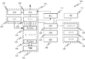
図1を参照すると、この図は、開示した主題に係る実施の形態におけるコンフォートユニット100の簡略化した概略図である。コンフォートユニット100は、他の部材の中に、熱規制モジュール102、空気供給モジュール104、及び感知モジュール106を備えることができる。熱規制モジュール102は、動作モードに応じて環境からの空気を加熱あるいは冷却可能である。空気供給モジュール104は、熱規制モジュール102からの調節された空気を、ユーザに向けて供給し、望ましいマイクロ環境を形成する。熱規制モジュール102は、ヒートポンプ120と蓄熱材料(TSM)122とを備えることができる。TSM122は、その内部に熱を蓄積するように構成される。以下により詳細に説明するように、TSM122は、センシブル材料あるいは相変化材料(PCM)から形成されてよい。例えば、センシブル材料は、加熱あるいは冷却した水、氷水、固体あるいは液体金属、不凍液、水グリコール混合物、油、あるいは当業者に知られた任意の第2の動作流体であってよい。
With reference to FIG. 1, this figure is a simplified schematic of the
例えば、PCMは、パラフィン、塩水和物、脂肪酸、水、あるいはそれらの組み合わせであってよい。代替的あるいは追加的に、PCMは、熱伝達に加えて、外部信号に基づいて相を変更するように構成されてよい。例えば、外部信号は、電圧信号、電流信号、及び超音波信号、磁気信号、あるいはそれらの組み合わせであってよい。ある実施の形態においては、外部信号は、単独あるいは熱交換とともに用いられてPCMをチャージしてその相を変更させる。 For example, PCM may be paraffin, salt hydrate, fatty acid, water, or a combination thereof. Alternatively or additionally, the PCM may be configured to change phase based on an external signal in addition to heat transfer. For example, the external signal may be a voltage signal, a current signal, and an ultrasonic signal, a magnetic signal, or a combination thereof. In certain embodiments, the external signal is used alone or with heat exchange to charge the PCM and change its phase.
ヒートポンプ120は、第1の熱交換器116と、第2の熱交換器118とを備えることができる。従って、熱は、熱交換器118を介してヒートポンプ120とTSM122との間で交換される。熱交換器116は、環境から空気を受け、熱をこの空気と交換する。暖房モードでの動作においては、熱規制モジュール102は、ヒートポンプ120を介して、TSM122に蓄積された熱を、熱交換器116を通る空気に伝達するよう動作する。一方、冷却モードでの動作においては、熱規制モジュール102は、ヒートポンプ120を介して、熱交換器116を通る空気からの熱を、TSM122に蓄積するよう動作する。例えば、ヒートポンプ120は、蒸気圧縮システムとして構成されてよい。しかしながら、他の種類のヒートポンプでも可能であり、例えば、熱弾性モジュール、熱電冷却機/モジュール、及び磁気カロリーシステムが挙げられるが、これに限定されない。ある実施の形態においては、ヒートポンプは、例えば、図4Eを参照して以下に説明するように、TSM122と内部に流れる空気との間で熱を伝達可能な単純な熱交換器に置換可能である。
The
熱規制モジュール102の冷却能は、約10〜500ワット、あるいは複数のユーザが同じコンフォートユニットを利用する場合には、ユーザ一人当たり約10ワット〜3キロワットである。熱規制モジュール102の暖房能は、最大で500ワット、あるいは複数のユーザが同じコンフォートユニットを利用する場合には、ユーザ一人当たり約200ワットである。空調装置が環境を維持する拡張温度構成においては、熱規制モジュール102の暖房/冷却能は、例えば、実質的に少なく、約10〜20ワットとなり得る。
The cooling capacity of the
空気供給モジュール104は、吸気口124、ファン126、及び排気口あるいは排出口128を備えることができる。環境からの空気は、吸気口124を介して吸気され、第1の熱交換器116を通過し、ここでファン126の動作によって空気が熱をヒートポンプ120と交換することができる。結果として得られる調節された空気は、ファン126によって排気口128に向けられ、ユーザに向けられてこのユーザが望むマイクロ環境が形成される。図示される構成に基づいて説明したが、開示した主題による実施の形態は、これに限定されない。例えば、図4Aに示すように、ファン126を、熱交換器116の他の側に配置する、すなわちブロースルー構成を採用してもよい。吸気口124は、例えば、1つ以上の調節弁、ノズル、スロット、あるいは当業者に知られた他の種の吸気口であってもよい。排気口128は、例えば、1つ以上の調節弁、ノズル、スロット、拡散器、あるいは当業者に知られた他の種の排気口であってもよい。ファン126は、例えば、ブラシレスDCモータを備えてよい。
The
空気供給モジュール104は、任意に、空気排出部128のための調整機構130を備えてもよい。調整機構130は、空気排出部128からの排出空気流の方向について、受動的(ユーザによる操作)あるいは能動的(内蔵式での運動制御)操作を可能にする。例えば、空気排出部128は、可能な限り多くの有効冷却/暖房を、最小のエネルギ消費で、冷却/暖房を要するユーザ及びユーザの体の一部に供給できるような、単一のノズル、あるいは複数のノズルによるアレイである。空気排出部128は、従って、調節された空気をユーザの体の選択した部位に向け、最適な効果及び熱感覚を形成する。調整機構130は、空気排出部128を、少なくとも1つの範囲、好ましくは3つの範囲で移動し、空気流を所望の目的を達する方向に向ける。例えば、冷却モードでは、排出空気は、ユーザの頭あるいは胴体上部に向けられ、一方で暖房モードでは、排出空気はユーザの足かさらに末端に向けられる。代替的あるいは追加的に、ユーザは、空気排出部128を調整機構130を介して操作して、空気流を望ましい身体部位に向け、例えば、冷たい手を温める。このような構成では、調整機構130は、延伸可能な部位を有し、この部位によってコンフォートユニット本体に対する排気口の高さ、及び/または排気口の位置を、ユーザあるいは制御モジュール108によって変更する。
The
コンフォートユニット100は、さらに、感知モジュール106を備えることができ、このモジュールは、IRカメラ132及び/または可視光線カメラ134を備えることができる。感知モジュール106は、1つ以上の追加の任意のセンサ136、例えば、バイオメトリックデータ及び/または環境データを計測するセンサ、コンフォートユニット100のナビゲーション制御のためのセンサ、環境をセキュリティ監視するためのセンサ、及び/または、運動制御(例えば、ジャイロ、加速、傾き、高度等)のためのセンサ、を備えてよい。IRカメラ132は、ユーザの衣服レベルや他の断熱物の程度を計測するためにユーザの画像を取得する用途に用いられ、これらのデータに基づいてユーザの快適さを判別することができる。可視光線カメラ134は、例えば、環境を通じてナビゲートを行うコンフォートユニット100によって用いられ、例えば、その経路における障害を検出する。代替的あるいは追加的に、可視光線カメラ134は、ユーザの画像を取得する用途に用いられ、これによってユーザの画像に対する顔認識処理がコンフォートユニット100によって行われ、ユーザ及びその好みが判別される。代替的あるいは追加的に、IRカメラ132及び/または可視光線カメラ134は、熱マイクロ環境の形成の間にユーザの画像を取得する用途に用いられ、ユーザの個別の熱に対する感覚に関するフィードバックを行なう。
The
さらに、コンフォートユニット100は、顔認識処理によって環境内のユーザを追跡し、またユーザを追いかける。代替的あるいは追加的に、感知モジュール106は、ユーザの位置及び/または環境における障害を検出するセンサを備える。例えば、感知モジュール106は、指向性無線信号、指向性無線周波数(RF)信号、及び/またはブルートゥース低エネルギ信号を用いることができる。代替的あるいは追加的に、ユーザはスマートフォンやウェアラブルのような通信装置を有してもよく、感知モジュール106がその装置を検出して追跡する。
Further, the
コンフォートユニット100は、さらに、制御モジュール108を備えることができ、この制御モジュールは、コンフォートユニット100の様々な態様及び動作を制御する。従って、制御モジュール108は、熱規制モジュール102、空気供給モジュール104、及び感知モジュール106に動作可能なように接続され、それらから信号を受信し、それらに制御信号を送信する。特に、制御モジュール108は、熱規制モジュール102及び/または空気供給モジュール104を、ユーザの快適さのレベルを示す信号に応じて制御可能である。従って、信号が示すようにユーザが不快な場合、制御モジュール108は、熱規制モジュール102及び/または空気供給モジュール104の向きを制御して、ユーザの好み(例えば、コンフォートユニット100に事前に入力される、あるいはユーザのバイオメトリックデータの感知に基づいて自律的に判別される)に基づいた熱マイクロ環境をユーザの周囲に形成してユーザを快適にする。
The
コンフォートユニット100は、さらに、追加のモジュール、例えば、任意の運動制御モジュール110、電源138、任意の補足モジュール114及び入力/出力(I/O)モジュール112を備えることができ、これらは動作可能なように制御モジュール108に接続される。運動制御モジュール110は、環境内でコンフォートユニット100を移動させる。運動制御モジュール110は、コンフォートユニット100の他のモジュールを支援可能であり、所望の動作を達成するためにモータ、ギア、ホイール等の任意の組み合わせを備えることができる。運動制御モジュール110は、制御モジュール108に動作可能なように接続されてコマンドを受け取り、このコマンドは、運動制御モジュール110を、例えば、ユーザを追跡させる、環境内の所定の経路に沿って移動させる、あるいは環境内の位置に動的に移動させて所望の動作(例えば、再チャージあるいは熱負荷シフト)を行わせる。運動制御モジュール110は、ロボット工学上のプラットフォームと考えることができるものである。
The
コンフォートユニット100は、環境から独立して動作するように構成されるので、内蔵式の電源138を備える。電源138は、コンフォートユニット100の他のモジュールのそれぞれに接続され(当該接続は明瞭には図示せず)、それらに電力を供給する。例えば、電源138は、リチウムイオン電池、亜鉛イオン電池、リチウムポリマー電池、ディープサイクル鉛酸蓄電池、及び亜鉛空気電池等の再チャージ可能な電池である。別の例として、電源138は、消耗に応じてユーザが交換可能な、取り外し可能な電池である。再チャージ可能あるいは取り外し可能な電池は、例えば、一体化の容易化及び交換の容易化のため、3−Dプリンティングによって非正規の形状に形成されてよい。代替的あるいは追加的に、電源138は、無線伝達された(例えば、コンフォートユニット100が置かれた床の中の)エネルギを利用可能な電力に変換する無線電力変換装置から構成されることができる。そのような無線送電システムは、誘導あるいは共振型のシステムであってよく、あるいは当業者に知られた他の構成を採用してもよい。
Since the
I/Oモジュール112は、制御モジュール108と、外部装置(例えば、以下に詳細に説明する、感知ユニット200、他のコンフォートユニット100、あるいは中央制御ユニット602)との間に通信リンクを提供することが可能である。通信リンクは、Wi−Fiネットワーク、セルラーネットワーク、ブルートゥース通信、ZigBee、ZWave、あるいは当業者に知られている他の無線通信プロトコルを介した無線通信リンクであってよい。代替的あるいは追加的に、I/Oモジュール112は、制御モジュール108とユーザとの間のコミュニケーションを可能にする。例えば、I/Oモジュール112は、オンデバイス式のユーザインターフェースを備え、これによってユーザはコンフォートユニット100と対話可能となり、所望の設定や他の要求を行うことができる。代替的あるいは追加的に、ユーザインターフェースは、コンフォートユニット100の本体と離れた位置、例えば、感知ユニット200上に配置され、I/Oモジュール112を介してコンフォートユニット100と通信してもよい。
The I /
補足モジュール114は、熱規制モジュール102及び空気供給モジュール104とは別の、あるいは補完する1つ以上の二次機能を提供することができる。例えば、二次機能は、熱規制モジュール102による空調の前あるいは後に行われる空気への追加的処理を含む。このような二次機能は、空気清浄、空気イオン化、給湿、及び除湿を含むが、これに限定されない。代替的あるいは追加的に、補足モジュール114によって提供される二次機能は、例えば、コンフォートユニット100によって伝送される情報の記憶媒体を設け、ユーザに用いられて、あるいは、感知モジュール106によるセキュリティ監視に基づいたアラートを処理及び提供することで、空気の処理と無関係なものであってもよい。
The
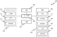
図2を参照すると、この図は開示した主題の実施の形態に係る感知ユニット200の簡略化した概略図である。感知ユニット200は、快適さのレベルについて環境の中のユーザ(あるいは複数のユーザ)を監視可能であり、コンフォートユニット100と共に動作してユーザの快適さのレベルを改善する。感知ユニット200は、バイオメトリックデータ感知モジュール202と、環境データ感知モジュール204と、データ処理あるいは制御モジュール206とを備えることができる。コンフォートユニット100のように、感知ユニットは、それ自体の電源210を備えることができ、この電源は、取り外し可能か再チャージ可能な電池、あるいは無線電力変換装置であってよい。感知ユニット200は、さらに、I/Oモジュール208を備えることができ、このモジュールは、上述したコンフォートユニット100のI/Oモジュール112と同様な、無線通信部、あるいはオンデバイスユーザインターフェースを備えることができる。
Referring to FIG. 2, this figure is a simplified schematic view of the
バイオメトリックデータ感知モジュール202は、心拍数212、皮膚コンダクタンス214、及び/または皮膚温度216を測定する少なくとも1つのセンサを備えることができる。データ処理モジュール206は、少なくとも検出されたバイオメトリックデータに基づいてユーザの快適さのレベルを示す計量を判別することができる。例えば、データ処理モジュール206は、低スペクトル周波数(LF)心拍数変動と、高スペクトル周波数(HF)心拍数変動との比を判別することができる。従って、心拍数センサ212には、LF帯域(例えば、0.04から0.15Hz)と、HF帯域(例えば、0.15から0.40Hz)とを区別するのに十分な精度が求められる。HFに対する高いLFの比は、ユーザに対する不快のレベルが高い場合に対応する。LF/HF比と他の計測とを組み合わせることで、ユーザの快適さのレベルのより明確なピクチャーを得ることができる。
The biometric
例えば、皮膚コンダクタンスは、ユーザの皮膚からの蒸発伝達に関連した皮膚の電気特性の変化を反映した電気皮膚反応として測定することが可能である。皮膚温度は、ユーザと環境との間の熱伝達の量を計測することに用いることができる。皮膚コンダクタンス及び皮膚温度の計測は、それぞれ、特定のユーザを示す所定の各領域、あるいは一般化されたユーザの好みと比較することができる。例えば、所定の領域は、コンフォートユニットのセットアップの間におけるユーザのフィードバックや、正常運転の間におけるユーザによる手動の介入、あるいはその他の手段に基づいて定めることができる。LF/HF比及びコンダクタンス並びに温度と所定の領域との比較に基づいて、システムは、ユーザの快適さのレベルを予測可能である。代替的にあるいは追加的に、心拍数、コンダクタンス、及び温度の測定は、快適さのレベルを示す計量と組み合わせることができる。 For example, skin conductance can be measured as an electro-skin reaction that reflects changes in the electrical properties of the skin associated with evaporation transmission from the user's skin. Skin temperature can be used to measure the amount of heat transfer between the user and the environment. Measurements of skin conductance and skin temperature can be compared to predetermined areas indicating a particular user, or generalized user preferences, respectively. For example, a given area can be defined based on user feedback during the comfort unit setup, manual intervention by the user during normal operation, or other means. Based on the LF / HF ratio and conductance as well as the comparison of temperature to a given area, the system can predict the level of comfort for the user. Alternatively or additionally, heart rate, conductance, and temperature measurements can be combined with measurements that indicate the level of comfort.
上述したように、コンフォートユニット100は、ユーザの画像を取得するIRカメラを備えてもよい。IR画像を分析することにより、最外層の衣服の温度と皮膚温度センサ216によって計測された温度とを比較することで、衣類の着用のレベルを推定できる。判別された衣服の着用のレベルは、ユーザと環境との間の全体的な熱伝達計算において抵抗要因を追加することができる。このデータは、I/Oモジュール208を介して、プロセッサ206で処理するために感知ユニット200に転送可能である。代替的あるいは追加的に、感知ユニット200からのデータは、快適さのレベルの処理及び判別のため、コンフォートユニット100あるいは個別の制御装置(例えば、図6Aの制御装置602)に転送可能である。
As described above, the
バイオメトリックデータを得るために、バイオメトリックデータ感知モジュール204のセンサは、ユーザの皮膚と直接接触してもよい。例えば、感知ユニット200、あるいはその一部は、時計、ブレスレット、ネックレス、胸当て、靴のインサート、下着あるいは腕章等のウェアラブル装置である。別の例においては、感知ユニット200あるいはその一部は、例えば、ユーザが断続的に触れてコンフォートユニットによる調整を起動するためのスタンドアロン装置であってよい。さらに別の例においては、感知ユニット200あるいはその一部は、コンフォートユニット100と一体化されてよい。これらの例を図5A乃至5Cに示し、以下により詳細に説明する。しかしながら、感知装置200も、上述した例の任意の組み合わせ、例えば、バイオメトリックデータ感知モジュール202用のウェアラブル装置、及び環境データ感知モジュール204用のスタンドアロン装置等であってもよい。1つ以上の考え得る実施の形態において、他の構成も可能である。
To obtain biometric data, the sensor of the biometric
環境データの感知モジュール204は、気温220、相対湿度222、気流速度224、乱流226、及び放射温度228等の環境あるいはマイクロ環境の様々な特性を測定する1つ以上のセンサを備えることができる。他のセンサ、例えば空気品質及びCO2センサ等も提供可能であるが、これに限定されない。個別の構成要素として示したが、環境データ感知モジュール204の単一のセンサが、1つ以上の変数を測定するようにしてもよい。例えば、全方向性の風速計を、乱流強度226とともに気流速度224を測定するために用いることもできる。別の例においては、放射温度228は、コンフォートユニット100のIRカメラ132からのデータ、あるいはグローブ温度計のような個別のセンサの使用に基づいて判別してよい。例えば、温度センサ(バイオメトリック及び環境の両方)は±0.5℃の精度を有し、湿度センサは2〜5%の精度を有する。
Environmental
バイオメトリックデータとともに、環境データが、ユーザのコンフォート状態を推定し、コンフォートユニット100を制御して、ユーザの快適さを向上するために望ましい空調を提供させる用途に適用できる。例えば、プロセッサ206は、バイオメトリックデータモジュール202及び環境データモジュール204からのデータを処理し、各データポイントを、快適さを示す各所定の範囲と比較してユーザの快適さのレベルを判別可能である。比較に基づいて、プロセッサ206は、ユーザの好みに基づいて、ユーザが寒く感じるか、暑く感じるか、あるいはニュートラルな感じか、を判別可能である。比較が不快さ(例えば、寒いあるいは熱い状態)を示す場合、コンフォートユニット100に信号を送り、ユーザがニュートラルな状態になるまで、自動的に空気供給位置、空気速度、熱容量、及び/または空調モード(例えば、暖房あるいは冷房)を調整させる。
Environmental data, along with biometric data, can be applied in applications that estimate the user's comfort state and control the
図3A〜4F及び9A〜9Dに、コンフォートユニットの例を示し、図5A〜5Cに感知モジュールの例を示す。図3A〜3Bは、コンフォートユニット100がユーザ300を追従するように移動させる運動制御モジュール110(例えば、ロボット工学上のプラットフォーム)によって支持された熱規制モジュール102及び空気供給モジュール104を備えた移動コンフォートユニット100の三次元モデルを示す。図3Bに示すように、空気供給モジュール104からの空気によって形成されたマイクロ環境は、ユーザ300とともに移動可能であり、環境におけるユーザの快適さを維持する。図3A〜3Bに示すコンフォートユニット100は、約1mの高さ(例えば、約900mm)、約0.5mの幅(例えば、直径約400mm)である。
3A-4F and 9A-9D show examples of comfort units, and FIGS. 5A-5C show examples of sensing modules. 3A-3B show a mobile comfort with a
図4Aは、熱規制モジュールにおけるヒートポンプ用の蒸気圧縮システムを用いるコンフォートユニット400の簡略化した横断面図である。図4Bは、図4Aに示す配置に類似するコンフォートユニット400のプロトタイプの写真である。コンフォートユニット400は、上記の運動制御モジュール(ロボット工学上のプラットフォーム)あるいは静止プラットフォームであり得るプラットフォーム402を備える。図4Aに示すように、プラットフォーム402は、コンフォートユニット400のいくつかの構成要素、あるいはコンフォートユニット400の全ての構成要素をサポート可能である。TSM406を収容する容器404が、プラットフォーム402にマウント可能である。
FIG. 4A is a simplified cross-sectional view of the
蒸気圧縮システムは、第1の熱交換器408と、コンプレッサ410と、第2の熱交換器412と、膨張弁414とを備え、これらはループを形成するように接続される。ループを流れる冷媒は、第1の熱交換器408と第2の熱交換器412との間で熱を伝達する用途に用いられる。ファン416は、空気を、熱伝達のために第2の熱交換器412を介して環境からブローすることができる。結果として得られる調節された空気は、1つ以上のノズル418を介して環境に排気可能である。第1の熱交換器408、例えば、チューブ及びフィン状熱交換器は、容器404内でTSM406に周囲を覆われていてもよく、それによって熱が熱交換器408とTSM406との間で伝達される。代替的に、第1の熱交換器408は、TSM406内に配置された1本以上のチューブを備えていてもよく、各チューブは、2mm未満の直径を有する。例えば、第1の熱交換器は、マイクロチャンネル熱交換器として機能し得る。
The vapor compression system comprises a
コンフォートユニット400が冷房モードで動作する場合、ファン416によって向けられた空気の熱は、第2の熱交換器412(つまり、エバポレータ)に吸収され、第1の熱交換器408(つまり、コンデンサ)に伝達され、TSMに蓄積される。この結果、空気排出ノズル418は冷却される。熱交換器408からTSM406に廃熱を蓄積することで、この熱が、ユーザの周囲の環境に排出されることを防止し、あるいはこの廃熱は、TSMによる蓄熱がない場合に必要となる。この結果、構造負荷は増加しない。吸収された熱は、構造負荷の増加及び/またはユーザの快適さを損なわないように後の時間(時間的シフト)あるいは異なる場所(空間的シフト)で放出される。例えば、TSMは、夜、あるいは構造負荷が問題とならない場所(過剰な空調とならない構造の外あるいは内側)に蓄積した熱を放出する。代替的あるいは追加的に、以下に詳細に説明するように、異なるエネルギ源を用いてTSM406を再チャージしてもよい。
When the
コンフォートユニット400は、暖房モードで動作するように蒸気圧縮システムを逆転するスイッチ(図示せず)を備えることができる。コンフォートユニット400が暖房モードで動作する場合、TSM406に蓄積された熱が、第1の熱交換器408(現在はエバポレータとして機能)から第2の熱交換器412(現在はコンデンサとして機能)に伝達され、熱がファン416によって向けられた空気に吸収される。これにより、空気排出ノズル418が加熱される。
The
ある実施の形態においては、TSM406は、相変化の際に熱を蓄積あるいは放出する相変化材料(PCM)である。適切なPCM材料としては、パラフィン、塩水和物、脂肪酸、水、及びそれらの組み合わせが挙げられるが、これらに限定されない。PCMは、標準室温よりわずかに上の溶融温度を有してもよく、それにより、冷房モードにおける熱伝達によって溶融し、暖房モードにおける熱伝達によって凝固し得る。 In certain embodiments, TSM406 is a phase change material (PCM) that stores or releases heat during a phase change. Suitable PCM materials include, but are not limited to, paraffin, salt hydrates, fatty acids, water, and combinations thereof. The PCM may have a melting temperature just above standard room temperature, which allows it to melt by heat transfer in cooling mode and solidify by heat transfer in heating mode.
ある実施の形態では、容器404は、TSM406とコンフォートユニット400の外部環境との間に複数の分離層を備えてもよい。例えば、容器404は外側層404a及び内側層404bを備えていてもよい。外側層404aは、内側層404bとは異なる断熱性(例えば、異なる断熱要因)を有してもよい。代替的に、外側層404aは、内側層404bと同じ断熱性を有するが、内側層404bとは異なる他の特性、例えば、異なる厚さ等を有してもよい。また別の代替においては、外側層404aは、内側層404bとほぼ同一であってもよい。外側層404aは内側層404bから取り外し可能であり、それによって容器404の断熱性を変更することができ、例えば、より多くの熱が、TSMと外部環境との間で伝達されるようになる。代替的にあるいは追加的に、内側層404bは、さらに、TSM材料と外部環境との間の熱伝達量を増加させるように取り外し可能であってもよい。
In certain embodiments, the
図4A及び図4Bを参照してコンフォートユニットの熱規制モジュールの特定の構成を示したが、さらに、1つ以上の別の実施の形態において他の構成も可能である。例えば、図4Cは、TSM406aを通って流れる空気を用いる蒸気圧縮システムを使用するコンフォートユニット400aの簡略化した断面図を示す。コンフォートユニット400aのいくつかの特徴は、図4Aに示したコンフォートユニット400と類似している。従って、図4Aと異なる特徴のみを以下に説明する。
Although specific configurations of the heat regulation module of the comfort unit are shown with reference to FIGS. 4A and 4B, other configurations are also possible in one or more other embodiments. For example, FIG. 4C shows a simplified cross-sectional view of a
図4Aにおいては、第1の熱交換器408は、TSM406に埋め込まれた。また、熱伝達が、熱交換器408中の冷媒とTSM406との間で生じた。一方、図4Bに示すコンフォートユニット400aは、ファン420が連結された第1の熱交換器408を有し、ファン420によって向けられた空気について第1の熱交換器408aを流れる冷媒によって熱伝達が行われる。その後、空気はTSM406a内の1つ以上の気流路を流れてTSM406aを介して流れて熱伝達を行う。TSM406aを流れた後、調節された空気は、例えば、排気口424を介して環境に排出される。
In FIG. 4A, the
別部材として示したが、ファン416及びファン420は、実際には同一のファンであり、一つのファンからの異なる空気路が、異なる熱交換器に繋がる。代替的あるいは追加的に、空気路のうちの1つは、(例えば、弁によって)遮断され、気流は熱交換器のうちの1つに主として向けられる。例えば、熱交換器412を通る気流路が遮断され、空気は熱交換器408aのみに流れ、環境からの空気を用いてTSM406aを再チャージすることが可能にする。
Although shown as separate members, the
図4Cは、独立した流体ループを介してTSM406bに連結された蒸気圧縮システムを使用するコンフォートユニット400bの簡略化した断面図である。コンフォートユニット400aのいくつかの特徴は、図4Aに示したコンフォートユニット400と類似している。従って、図4Aとは異なる特徴のみを以下に説明する。
FIG. 4C is a simplified cross-sectional view of the
上述したように、図4Aにおいては、第1の熱交換器408はTSM406に埋め込まれ、伝達は、熱交換器408の冷媒とTSM406との間で行われた。一方、図4Cのコンフォートユニット400bは、第1の流体ループ430及び第2の流体ループ432が、互いに熱的に連通するようにして配置された第1の熱交換器408bを備える。ポンプ428は、熱交換器408bとTSM406bとの間の第2の流体ループ432を通って流体を移動させる。従って、熱は、第1の流体ループ432からTSM406bに第2の流体ループ432を介して伝達可能である。
As mentioned above, in FIG. 4A, the
代替的な態様においては、TSMは、三次元多孔質構造あるいはマトリクス(例えば、スポンジ)として構成することができる。従って、空気は、連結された複数の孔のネットワークを介してTSMを通って流れ、流れる空気とTSMとの間で熱伝達を可能にする。このような態様においては、TSMは、相変化材料(PCM)であってよく、従って熱によってその構成を失う。このような態様を、図4E及び4Fに示す。例えば、容器404C内に配置されたPCM406cは、全体に分散された孔456のネットワークを備えることができる。ファン/熱交換器アセンブリ450は、容器404cの上部に連結され、空気流452を、容器内に中央フローチャンネル454に沿って向ける。フローチャンネル452内の空気は、好適な熱交換のために孔を介してPCM406cへと流れ込む。別の排気チャンネル(図示せず)がPCM406cから容器404c及び/またはコンフォートユニットの外部に排出するために設けられてもよい。
In an alternative embodiment, the TSM can be configured as a three-dimensional porous structure or matrix (eg, sponge). Thus, air flows through the TSM through a network of connected plurality of holes, allowing heat transfer between the flowing air and the TSM. In such an embodiment, the TSM may be a phase change material (PCM) and therefore lose its composition by heat. Such an embodiment is shown in FIGS. 4E and 4F. For example, the PCM406c disposed within the container 404C can include a network of
別の態様(図示せず)においては、蒸気圧縮サイクルで動作する熱規制モジュールは、単一の回転アセンブリとして構成される。コンプレッサは、コンプレッサモータが駆動されると全密閉コンプレッサが回転するように取り付けられた密閉コンプレッサであってよい。例えば、ロータが静止あるいはステータよりとても遅い速度で回転する間、自由に回転できるようにコンプレッサシェルがマウントされてよい。冷房モードでは、圧縮冷媒蒸気は、コンデンサに放出可能であり、コンデンサは、コンプレッサの外部と共に回転する空気移動装置(例えばファン)を備えることができる。圧縮冷媒蒸気は、コンデンサのファンブレードの内部の流路において凝集する。コンデンサから放出された液体冷媒は、好適なエキスパンション装置を通ってエバポレータに流れ、エバポレータは、別の空気移動装置(例えばファン)を備えることができる。冷媒は、環境からの空気にさらされることでエバポレータのブレードの中で蒸発可能であり、これによって空気を冷却する。コンプレッサ、コンデンサ空気移動装置、エキスパンション装置、及びエバポレータ空気移動装置は、密閉された単一の回転アセンブリの一部となり得る。 In another aspect (not shown), the heat regulation module operating in a steam compression cycle is configured as a single rotating assembly. The compressor may be a closed compressor mounted so that the fully closed compressor rotates when the compressor motor is driven. For example, the compressor shell may be mounted to allow free rotation while the rotor is stationary or rotating at a much slower speed than the stator. In cooling mode, the compressed refrigerant vapor can be discharged to the condenser, which can include an air transfer device (eg, a fan) that rotates with the outside of the compressor. The compressed refrigerant vapor aggregates in the flow path inside the fan blade of the capacitor. The liquid refrigerant discharged from the condenser flows to the evaporator through a suitable expansion device, and the evaporator can be provided with another air transfer device (for example, a fan). The refrigerant can evaporate in the evaporator blades when exposed to air from the environment, thereby cooling the air. Compressors, condenser air transfer devices, expansion devices, and evaporator air transfer devices can be part of a single, sealed rotating assembly.
具体的に上述した態様あるいは他の態様に加え、空気とTSMとの間の熱伝達を効率化する態様が、1つ以上の実施の形態において可能である。従って、開示した主題に係る実施の形態は、本明細書で詳細に説明した態様に限定されない。 Specifically, in addition to the above-mentioned aspects or other aspects, an embodiment for improving the efficiency of heat transfer between air and TSM is possible in one or more embodiments. Therefore, embodiments relating to the disclosed subject matter are not limited to the embodiments described in detail herein.
図5Aを参照し、ユーザによって着用可能な感知ユニット500の実施の形態を示す。感知ユニット500は、例えば、時計やブレスレットのようなユーザの手首にユーザによって着用されるように構成される。上述したように、感知ユニット500は、心拍数センサ212、皮膚コンダクタンスセンサ214、及び皮膚温度センサ216等の1つ以上のバイオメトリックセンサを備えることができる。感知ユニット500は、さらに、任意に1つ以上の環境センサ204を備えることもできる。バイオメトリックセンサは、ユーザの皮膚と常時あるいは定期的に接触するよう感知ユニット500上に配置されてよい。1つ以上の環境センサ204は、ユーザの皮膚から離間して主に環境に向けられるように感知ユニット500上に配置されてもよい。
FIG. 5A shows an embodiment of the
感知ユニット500は、さらに、例えば、ユーザが視認可能に配置された多機能モジュール502を備えることができる。多機能モジュール502は、例えば、ユーザインターフェースまたはディスプレイ504、入力/出力モジュール506、電源508、及び/または制御モジュール510を備えることができる。制御モジュール510は、バイオメトリック及び環境センサからのデータ信号の処理を含む感知ユニット500の動作を制御可能である。電源508は、制御モジュール510及び感知ユニット500の他の要素に電力を供給可能である。例えば、電源508は、バッテリである。入力/出力モジュール506は、バイオメトリック及び環境センサからコンフォートユニットあるいは他のシステム制御ユニットにデータ信号を通信する用途に用いられる。例えば、入力/出力モジュール506は、無線あるいはブルートゥース通信を採用することができる。感知モジュール500を着用しているユーザは、ディスプレイ504を介して、例えば、バイオメトリック及び環境センサによって計測された値を視認し、手動制御におけるコンフォートユニットに指示、システムをオン、オフ、あるいは他の目的のため当該感知ユニットと通信する。
The
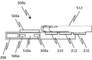
感知ユニットの特定の態様を図5Aに示したが、さらに、1つ以上実施の形態によって他の態様も可能である。例えば、図5Bは、感知ユニットの別の態様の簡略化した側面図である。図5Aのウェアラブル感知ユニットとは対照的に、感知ユニット500aは、ユーザとの定期的な接触のためのスタンドアロンユニットとして構成される。例えば、感知ユニット500aは、ユーザが作業をする机上に配置され、ユーザが様々な時にタッチすることでそれらの快適さのレベルの表示を提供する。別の例において、感知ユニット500aは、コンフォートユニットを起動するためにユーザが触れる壁に取り付けられる、あるいはマウントされてもよい。
A particular embodiment of the sensing unit is shown in FIG. 5A, but other embodiments are also possible depending on one or more embodiments. For example, FIG. 5B is a simplified side view of another aspect of the sensing unit. In contrast to the wearable sensing unit of FIG. 5A, the
上述したように、感知ユニット500aは、心拍数センサ212、皮膚コンダクタンスセンサ214、及び皮膚温度センサ216等の1つ以上のバイオメトリックセンサを備えることができる。感知ユニット500aは、さらに、任意に1つ以上の環境センサ204を備えることもできる。バイオメトリックセンサは、ユーザが手512あるいはその他の身体部位上に配置して接触するように、感知ユニット500a上に配置されてよい。1つ以上の環境センサ204は、主に環境に向けられるように感知ユニット500aに配置されてもよいし、ユーザがタッチする場所から離間した位置に配置されてもよい。
As described above, the
感知ユニット500aは、さらに、例えば、ユーザインターフェースあるいはディスプレイ504a、及び入力/出力モジュール506a、電源508a、及び/または制御モジュール510aを備える。感知モジュールの別の上記の実施の形態において、制御モジュール510aは、バイオメトリック及び環境センサからのデータ信号の処理を含む感知ユニット500aの動作を制御可能である。電源508aは、制御モジュール510a及び他の感知ユニット500aの要素に電力を供給可能である。例えば、電源508aはバッテリ、無線電力の変換器、あるいは建物もしくは他の外部電源の電力への有線接続であってよい。入力/出力モジュール506aは、バイオメトリック及び環境センサからコンフォートユニットあるいは他のシステムコントロールユニットにデータ信号を伝達する用途に用いられる。例えば、入出力モジュール506は、無線やブルートゥース通信、あるいは環境の内部もしくは外部ネットワークへの有線接続を適用可能である。
The
感知ユニットのさらに別の態様においては、感知ユニットの1つ以上の様態がコンフォートユニットと一体化される。図5Cは、そのような実施の形態を示し、コンフォートユニット400cは、例えば、心拍数、皮膚コンダクタンス、及び皮膚温度等の所望のバイオメトリックデータを提供するためにユーザがタッチできるタッチパッド514を備える。例えば、ユーザは、最初にコンフォートユニット400cをオンにする時、そしてその後、例えば、環境が不快であると考えた時に断続的に、タッチパッド514をタッチする。上述のように、コンフォートユニット400cは、さらに赤外線カメラ516及び可視光線カメラ518等の1つ以上のカメラを備えていてもよい。赤外線カメラ516は、ユーザの衣服によって提供される断熱の程度を推定する用途に用いられ、可視光線カメラ518は、環境においてユーザを特定及び/または追跡する、ならびに/もしくは環境中の障害を避ける用途に用いられる。
In yet another aspect of the sensing unit, one or more aspects of the sensing unit are integrated with the comfort unit. FIG. 5C illustrates such an embodiment, the
さらに、具体的に上述した態様及び他の態様に加えて、1つ以上の実施の形態において、バイオメトリック及び環境データを感知する他の態様が可能である。従って、開示した主題の実施の形態は、本明細書で詳細に説明した態様に限定されない。 Further, in addition to the embodiments and other embodiments specifically described above, in one or more embodiments, other embodiments that sense biometric and environmental data are possible. Accordingly, embodiments of the disclosed subject matter are not limited to the embodiments described in detail herein.
コンフォートユニットは、例えば、中央空調ユニット等の既存のビルディングインフラとともに用いることが可能であり、全面的なエネルギ消費を削減しつつ、ユーザの快適さのレベルを改善する。この意味で、ビルディングインフラ及びコンフォートユニット(あるいは複数のコンフォートユニット)の制御は、望ましい快適さ及びエネルギ目的を達成するために共働的となり得る。図6Aを参照すると、この図は、既存のビルディングインフラと上記のコンフォートユニットとを組み込む環境制御システム600の簡略化した概略図である。従って、環境制御システム600は、ビルディングHVACシステム604と、コンフォートユニット100と、感知ユニット200と、中央制御システム602と、を備える。中央制御システム602は、環境制御システム600の異なる要素に接続可能であり、所望の制御を達成する。
The comfort unit can be used with existing building infrastructure, such as a central air conditioning unit, to improve the level of user comfort while reducing overall energy consumption. In this sense, control of the building infrastructure and comfort units (or multiple comfort units) can be synergistic to achieve the desired comfort and energy objectives. Referring to FIG. 6A, this figure is a simplified schematic of an
既存のビルディングインフラは、ビルディングHVACシステム604に加え、ビルディングHVACシステム604を使用して環境の温度を制御するためのフィードバックとして用いる1つ以上のビルディングセンサ606を備えることができる。コンフォートユニット100及び感知ユニット200は、環境及び/またはユーザの快適さのレベルに関する追加のデータを共有可能である。例えば、コンフォートユニット100及び/または感知ユニット200は、無線ネットワークを介して中央制御システム602と通信可能である。コンフォートユニット及び/または感知ユニットによって集められた感知情報は、ビルディングHVACシステム604のよりよい制御に用いることができる。さらに、現在及び/または予測的な気象通報も、ビルディングHVACシステム604及び/またはコンフォートユニット100の予測的モデリング及び制御のために(例えば、インターネットを介して)取得可能である。
The existing building infrastructure can include, in addition to the
中央制御システム602は、ユーザの熱的な快適さのフィードバックを利用して省エネルギアルゴリズムを採用し、コンフォートユニット100及びビルディングHVACシステム604の両方を制御し、全体的なエネルギ消費を削減する。例えば、これは、一時的あるいは連続的な手法でビルディングHVACシステム604のゾーン設定点温度を緩和することで達成できる。コンフォートユニット100は、これら緩和の期間におけるユーザの熱的な快適さを維持する。中央制御システム602は、例えば、ビルディングゾーンレベルで温度設定点を緩和し熱的な快適さのバランスを図るアプリケーションプログラミングインターフェースを用いたサーバである。例えば、暖房が望まれる日に、ビルディングHVACシステム604の設定点が低下される。一方、冷房が望まれる日に、ビルディングHVACシステム604の設定点が上昇される。
The
中央制御システム602は、これらに限定されないが、時刻、利用率、地域の天候、現在のビルディングHVAC設定、ユーザの熱的な快適さに関するフィードバック、及び利用可能なコンフォートユニットの数及び/または容量等の要因及び入力の数に基づいてゾーン温度を設定可能である。これらの省エネルギゾーン温度緩和期間にコンフォートユニットを利用することで、後の熱管理のために熱を保存するように一時的に作用することができる一群(1つ以上)の個別化された冷房がもたらされる。例えば、これらの緩和の期間に、HVACシステムによって維持された温度は、少なくとも4度、ユーザの快適さを維持するように設定された温度から異なる(高いあるいは低い)。コンフォートユニット100は、次に、環境から少なくとも4度異なる温度のマイクロ環境を、ユーザの周囲に維持し、これによって不快な環境温度にもかかわらずユーザの快適さのレベルを維持する。
The
図6Aには単一のコンフォートユニット100のみを示したが、1つ以上の実施の形態において、複数のコンフォートユニットを単一の設定において使用可能である。このような構成では、各コンフォートユニットは、例えば無線ネットワーキングによって、近接する周囲の他のコンフォートユニットと通信可能である。例えば、複数のコンフォートユニットは、個別に動作可能で、それぞれが単一のユーザあるいはユーザのグループにカスタマイズされたマイクロ環境を提供する。代替的あるいは追加的に、複数のコンフォートユニットは、協動して1人以上のユーザにカスタマイズされたマイクロ環境を提供することもできる。
Although only a
また、環境制御システムは、コンフォートユニット100、感知ユニット200、及び/または中央制御システム602間で望ましい通信を可能にする構成要素を備えることもできる。例えば、環境制御システム600の基礎となる通信プラットフォームは、オンデバイスセンサ、ユーザ上のセンサ、異なるビルディングゾーンにおけるユーザ及び/またはコンフォートユニットを検出するブルートゥース低エネルギビーコン、及びコンフォートユニットと通信するサーバを備えることができる。さらに、コミュニケーションプラットフォームは、ローカルあるいはクラウドベースのサーバ上で実行可能な、装置及びビルディングアプリケーションプログラムインターフェースを用いる制御通信サービスを利用することもできる。例えば、制御通信サービスは、制御及びビルディング自動化システム設定を読み書きするウェブサービス、任意の数のコンフォートユニット設定用の制御を読み書きするウェブサービスを備えることができる。制御及びビルディング自動化システム設定は、ゾーンレベル温度設定点及び換気率を含むことができるが、これらに限定されない。コンフォートユニット設定は、ファン速度、暖房/冷房モード、供給空気の温度、位置、蓄熱レベル、蓄熱排気、及び空気分散制御(複数のノズルを有する装置用)を含むことができるが、これらに限定されない。
The environmental control system may also include components that allow desirable communication between the
図6Bは、独自のHVACシステムを有するビルディング内での複数のコンフォートユニット100の使用を示す。例えば、HVACシステムは、環境616から空気を取り入れる吸気口レジスタ611と、HVACからの調節された空気を環境616に向ける排気レジスタ510とを備えてよい。図示するように、各ユーザ612a、612bは、それぞれ、環境616内でカスタマイズされたマイクロ環境614a、614bをユーザの周囲に提供するコンフォートユニット100を有する。コンフォートユニット100は、図6Cに概略的に示すように、例えば、HVACシステムが無いビルディングや乗り物内、あるいはアウトドア等のビルディングHVACが利用可能でない環境618内で同様に動作してよい。
FIG. 6B shows the use of
以上の説明は、単一のユーザによるコンフォートユニットの使用について焦点を置いたが、開示した主題に係る実施の形態はそれらに限定されない。全体的に不快な環境において複数のユーザによってコンフォートユニットが使用され、より快適なマイクロ環境を提供するようにすることも可能である。例えば、コンフォートユニットは、複数のユーザに同時に空気を向ける複数のノズルを備えることができる。このような構成においては、各ユーザに向けられた気流は、各ユーザが自分用のマイクロ環境を有することができるようにカスタマイズ(例えば、異なる温度及び/または湿度レベル)可能である。別の構成においては、各ユーザに向けられた気流は、実質的に同一で、全てのユーザに共通のマイクロ環境を形成することもできる。別の例においては、コンフォートユニットは、各ユーザに連続して別々に直接空気を向けるようにノズルを移動(例えば、揺らす、あるいは首振りさせる)、あるいはコンフォートユニット自体が移動可能である。 Although the above description has focused on the use of comfort units by a single user, embodiments relating to the disclosed subject matter are not limited thereto. It is also possible for the comfort unit to be used by multiple users in an overall unpleasant environment to provide a more comfortable micro-environment. For example, a comfort unit may include multiple nozzles that direct air to multiple users at the same time. In such a configuration, the airflow directed to each user can be customized (eg, different temperature and / or humidity levels) so that each user can have their own microenvironment. In another configuration, the airflow directed to each user is substantially the same, which can also form a common microenvironment for all users. In another example, the comfort unit may move the nozzle (eg, rock or swing) to direct air directly to each user in succession, or the comfort unit itself may move.
上記の説明は単一のコンフォートユニットの使用に焦点を置いたが、開示した主題に係る実施の形態はそれらに限定されない。むしろ、1つ以上の実施の形態において、複数のコンフォートユニットを同時に用いて、マイクロ環境の組み合わせあるいは別々のマイクロ環境を形成することも可能である。例えば、単一のユーザは、複数のコンフォートユニットによるサービスを、異なる身体部位に向けられた異なる温度気流で受けることができる。別の例においては、複数のユーザは、会議または会合の間に、複数のコンフォートユニットによるサービス受けることができる。 Although the above description has focused on the use of a single comfort unit, embodiments relating to the disclosed subject matter are not limited thereto. Rather, in one or more embodiments, multiple comfort units can be used simultaneously to form a combination of microenvironments or separate microenvironments. For example, a single user can be serviced by multiple comfort units in different temperature airflows directed at different body parts. In another example, multiple users may be serviced by multiple comfort units during a conference or meeting.
コンフォートユニット100の蓄熱管理は、緩和期間における低減されたエネルギ消費に加え、別の省エネルギ方法を提供する。蓄熱は、中央制御システムによって、例えば、上述したウェブサービスアプリケーションプログラミングインターフェースを用いて管理可能である。コンフォートユニットの蓄熱管理は、2つの手法がある。一つ目は、熱負荷の時間的なシフトである。この場合、中央制御システムは、使用されていない期間において、ビルディングやアウトドア環境へ熱容量を放出するように1つ以上のコンフォートユニットを調整する。
The heat storage management of the
2つ目は、熱負荷の空間的なシフトである。この場合には、中央制御システムは、1つ以上のコンフォートユニットを、空調が過剰あるいは不十分なビルディング内の特定のゾーンに物理的に移動させ、熱負荷を空間的にシフトするように調整する。このような場合を、図7に概略的に示す。まず、コンフォートユニット100は、ゾーン702a内でユーザの周囲にマイクロ環境を提供する。例えば、冷房動作モードで動作する場合、コンフォートユニット100は、廃熱を内蔵式TSMに蓄積する。コンフォートユニット100の内蔵式TSMを使い切った後、例えば、中央制御システムは、コンフォートユニット100を異なるゾーン、例えば温度TCがゾーン702aの温度TA未満であるゾーン702cに向ける。温度の差は、例えば、ゾーン702cの過剰な空調、あるいはシステムにおける異なる負荷や他の不均衡によるものである。ゾーン702cにおいて、一度、コンフォートユニット100は、そのTSM内の熱を放出し、ゾーン702cの温度を上昇させる。代替的あるいは追加的に、コンフォートユニット100は、ビルディング環境における変化を避けるために、アウトドア位置704に移動し、熱を放出する。例えば、蓄積された熱は、排気口を介してTSMから放出、あるいはコンフォートユニットの逆動作(つまり、以前にゾーン702aで冷房を提供していた場合、ゾーン702cで暖房を提供する)によって熱を放出する。
The second is the spatial shift of the heat load. In this case, the central control system adjusts the heat load to spatially shift by physically moving one or more comfort units to a specific zone in the over-air-conditioned or under-air-conditioned building. .. Such a case is schematically shown in FIG. First, the
コンフォートユニットのビルディングのゾーン間を物理的に移動し、中央制御システムと通信する能力によって、中央制御システム、より具体的には、その制御アルゴリズムは、ビルディング内の過剰及び不足が解消された熱的ゾーン間で短時間に熱負荷をシフトできる。また、環境制御システムは、蓄積された熱を、ゾーンの状況、アウトドア状況、及びビルディングの使用状態を考慮して、いつ、どこで放出すると最適かつ最も効率的になるか制御可能である。蓄積された熱を周囲環境、あるいはアウトドア環境に放出することで、コンフォートユニットによってTSMをさらに使用できるように再チャージ/再生して、ユーザに好適なマイクロ環境を提供できるようになる。周囲温度がTSMの再チャージに不十分な場合、ビルディングHVACシステムは、電源が投入されて再チャージを支援する。 The ability to physically move between zones in a comfort unit building and communicate with a central control system allows the central control system, and more specifically, its control algorithms, to eliminate excesses and deficiencies within the building. The heat load can be shifted between zones in a short time. Environmental control systems can also control when and where the stored heat is optimally and most efficiently released, taking into account zone conditions, outdoor conditions, and building usage. By releasing the accumulated heat to the surrounding environment or the outdoor environment, the comfort unit can recharge / regenerate the TSM so that it can be used further, and provide a suitable micro environment for the user. If the ambient temperature is insufficient to recharge the TSM, the building HVAC system is powered on to assist in recharging.
上述した時間的シフト及び空間的シフトに加え、開示した主題に係る実施の形態は、使い切った後にコンフォートユニット100のTSMの再チャージを行えるようにし、この再チャージは、どの時間あるいは空間的シフトの必要性からも独立したものである。ここにおける再チャージの用語は、TSMの温度及び/または相を変化させて、コンフォートユニットによって、ユーザにマイクロ環境を形成するために即座に利用可能であることを意味する。ある実施の形態においては、このようなTSMの再チャージ/再生は、図8Aに概略的に示すように、個別のチャージングステーション806において行われる。
In addition to the temporal and spatial shifts described above, embodiments of the disclosed subject matter allow the TSM of the
コンフォートユニット802aは、望ましいマイクロ環境を、内蔵式TSMを使い切るまでユーザ612に提供するように動作可能である。この時点で、コンフォートユニット802aは、望ましいマイクロ環境614を維持することができなくなるか、あるいは、動作を継続するためにTSMに蓄積されたエネルギを放出しなければならなくなる。従って、コンフォートユニット802aは、環境616内のチャージングステーション806に移動し、チャージ接続部808が、コンフォートユニットの再チャージ口804に接し、TSMを再チャージ、例えば、その温度及び/または相を変更させる。同時に、チャージングステーション806は、コンフォートユニット上の内蔵式バッテリを充電し得る。チャージングステーション806は、一度に単一のコンフォートユニット802bにサービスを行う、あるいは複数のコンフォートユニットに一度にサービスを行い得る。
The
図8Aにコンフォートユニット100を再チャージする具体的な構成を示したが、1つ以上の実施の形態において、他の構成も可能である。例えば、内蔵式TSMは、取り外し可能なキャニスタや容器内でコンフォートユニットに保持されてもよい。一度TSMが使い切られた後、キャニスタが取り外されて別の再チャージあるいは蓄積ステーションに移され、新たなキャニスタに交換される。代替的あるいは追加的に、例えば、暖房モードで使用するTSMが冷房モードで使用するTSMと異なる場合、TSMが取り外されて動作モードが変更される。このような構成を図8Bに示し、使い切ったTSMカートリッジ812aは、コンフォートユニット802cのアクセスドア810を介して取り外され、チャージング/保管ステーション814において再チャージされたTSMカートリッジ812bあるいは別の保管されたTSMカートリッジ812cと交換される。
Although a specific configuration for recharging the
別の例において、内蔵式TSM812d及びヒートポンプ816aは、共にコンフォートユニット802dから取り外し可能であり、個別にあるいは共に取り外し/交換される。例えば、TSM812d及びヒートポンプ816aは、アクセスドア810を介して取り外し可能な共通ハウジング818内に共に配置される。新しいユニット、例えば、完全にチャージされたTSM812a及びヒートポンプ816bを、コンフォートユニット802dに装填可能である。図8Bの実施の形態において、例えば、動作モードを変更するため、TSMは、異なるTSM812f及び/または異なるヒートポンプ816cと交換される。ヒートポンプ及びTSM全体をコンフォートユニットから取り替えることができるので、TSMとヒートポンプの熱交換器との間の気密性が向上し得る。
In another example, the built-in TSM812d and the
さらに別の例において、コンフォートユニット自体が、内蔵式再生モジュール、例えば、TSMが一度使い切られた場合に所定の時間動作してTSMを再チャージする個別の蒸気圧縮システムを備えることができる。例えば、ある実施の形態では、VCSが、TSMを内蔵式で再生するよう動作する。例えば、VCSは、TSMに熱を蓄積する第1の作動モードで動作する。第2の作動モードにおいて、VCSはサーモサイフォンとして動作する。TSMに蓄積された熱は、VCSの熱交換器を介して周囲環境に放出され、VCSの動作用流体は、TSMと低温の周囲環境との間の温度差によって生じた密度差で駆動される。 In yet another example, the comfort unit itself may include a built-in regeneration module, eg, a separate vapor compression system that operates for a predetermined time to recharge the TSM once it has been used up. For example, in some embodiments, the VCS operates to regenerate the TSM in a built-in manner. For example, the VCS operates in a first mode of operation that stores heat in the TSM. In the second mode of operation, the VCS operates as a thermosiphon. The heat stored in the TSM is released to the ambient environment via the VCS heat exchanger, and the working fluid of the VCS is driven by the density difference created by the temperature difference between the TSM and the cold ambient environment. ..
コンフォートユニットの構成、特に、暖房または冷房のためにPCMを用いたコンフォートユニットの構成について、以上説明したが、開示した主題に係る実施の形態はそれらに限定されない。むしろ、1つ以上の実施の形態において他の構成も可能である。例えば、コンフォートユニットは、センシブル冷房モードと除湿モードとの間でモードが切り替わるように構成され得る。図9Aは、そのような機能を有するコンフォートユニット910の簡略化した断面図である。コンフォートユニット910のいくつかの特徴は、図4Aに示したコンフォートユニット400と類似している。従って、図4Aとは異なる特徴のみを以下に説明する。
The configuration of the comfort unit, particularly the configuration of the comfort unit using PCM for heating or cooling, has been described above, but the embodiments relating to the disclosed subject matter are not limited thereto. Rather, other configurations are possible in one or more embodiments. For example, the comfort unit may be configured to switch modes between sensible cooling mode and dehumidifying mode. FIG. 9A is a simplified cross-sectional view of the
図9Aでは、コンフォートユニット910は、熱交換器408を介して空気からTSM406に熱を蓄積するための冷房モードの間に動作する。除湿作動モード中に、熱交換器408、412の1つの内の凝集水分が、導管914を介して凝集タンク912に運ばれ、後の使用、例えば飲料、注水、ビルディングサプライの補充、あるいは他の使用のために貯蔵される。貯蔵水は、例えば、任意のポート/排出口916を介して取り出すことができる。
In FIG. 9A, the
図9Bは、TSMが非PCM材料、例えば、単相(あるいは実質的に単相)液体あるいは固体材料、例えば、金属や水(もしくは氷水)から構成される場合の別のコンフォートユニット920の簡略化した断面図である。コンフォートユニット920のいくつかの特徴は図4Aに示すコンフォートユニット400と類似している。従って、図4Aと異なる特徴のみを以下に説明する。
FIG. 9B simplifies another
コンフォートユニット920は、単相材料922を内包する断熱容器924を備え、熱交換器408が単相材料922と熱的に接触している。熱交換器408によって伝達された熱は、温度を変えることで、単相材料922に蓄積(あるいは単相材料から放出)することができる。単相材料922が液体である場合、アクセス弁926を備えた注入口/排出口928を、容器924に対して液体を追加/取り除くために用いることができる。
The
例えば、単相材料922が冷やしたあるいは氷水である場合、コンフォートユニット920は、冷房マイクロ環境を提供することができる。冷やした水は、既存のビルディングインフラ(例えば、HVACシステム)あるいはスタンドアロンの水冷却ステーションのいずれかから得ることができる。マイクロ環境の提供のための使用の後、この時点での温水が節水のためにビルディング冷却システムに戻され得る。開放型水システムにおいては、生水が、冷やした空気を提供するために蒸発器の中で使用され得る。別の例においては、単相材料922が温水である場合、コンフォートユニット920は暖房マイクロ環境を提供することができる。温水は、既存のビルディングインフラ(例えば、温水ヒーター)あるいはスタンドアロンの温水ステーションから得ることができる。
For example, if the single-
図9Cは、放射パネル948を、TSM954に加えてあるいは代えて使用するコンフォートユニット940の簡略化した断面図である。コンフォートユニット940のいくつかの特徴は図4Aのコンフォートユニット400と類似している。従って、異なる特徴のみを以下に説明する。
FIG. 9C is a simplified cross-sectional view of the
上述した構成のように、熱はヒートポンプ流体ループ956を介して空気と熱交換器946との間で伝達される。しかしながら、熱交換器946は、流体ループ952を介してTSM954に熱的に接触することに加え(あるいはその代わりに)、流体ループ958を介して放射パネル948と熱的に接触していてよい。放射パネル流体ループ958は、1つ以上の流体導管950を備えることができ、放射パネル948の裏側領域に沿って冷媒(あるいは他の流体)を循環させ、その温度を制御する。従って、ノズル418からの冷房あるいは暖房気流942に加え、放射パネル948は、ユーザに放射による熱伝達944を提供する。放射による熱伝達は、強制対流のみよりも熱的な快適さを改善し得る。
As in the configuration described above, heat is transferred between the air and the
放射パネル948を単一の連続パネルとして図示したが、実施の形態はこの場合に限定されない。複数の接続したあるいは個別の放射パネルを、同一のコンフォートユニット上に設けてもよい。一例として、放射パネルは分割されてもよい。別の例においては、異なる放射パネルが異なる温度、例えば、ユーザの低位置の末端に対して暖かい温度を提供し、他の放射パネル及び/またはエアノズル418がユーザの身体上部に冷房効果を提供するように動作する。
The
図9Dは、コンフォートユニット900のさらに別の構成を示し、複数のノズル418a、418bが、同時にユーザ(あるいは複数のユーザ)に個別の暖房及び冷房を提供する。コンフォートユニット900のいくつかの特徴は、図4Aに示すコンフォートユニット400と類似している。従って、図4Aと異なる特徴のみを以下に説明する。
FIG. 9D shows yet another configuration of the
図4Aでは、第1の熱交換器408は、一度に単一の動作モードのみを可能とする。一方、図9Dのコンフォートユニット900は、例えば、個別の独立した流体ループ(図示せず)を用いることで、TSM406cに熱を伝達し、またTSM406cから熱が伝達されることが同時に可能である第1の熱交換器904を備える。このような構成によって、ユーザは、異なる身体部位あるいは領域が異なる温度を体感できる勾配マイクロ環境を経験できるようになる。例えば、ユーザの足が1つのノズル418bからの空気によって暖められ、ユーザの身体上部が他のノズル418aによって冷却される。
In FIG. 4A, the
従って、ファン416aは、空気に第2の熱交換器412を通過させ、例えば、ノズル418aを介して冷房気流を供給するように第1のモードで動作する。従って、空気からの熱は、熱交換器904を介してTSM406cに蓄積される。同時に、ファン416b(ファン416aと同じあるいは別の個別のファンであってよい)は、空気に熱交換器902を通過させ、例えば、ノズル418bを介して暖房気流を供給するように第2のモードで動作する。TSM406cからの熱は、この空気を加熱するために熱交換器904から放出される。
Therefore, the
図10は、開示した主題に係る実施の形態に係る1つ以上の制御ユニットを用いた環境制御のための汎用の方法を示す。例えば、この汎用の方法は、独立してあるいは協働で動作する1つ以上の制御ユニット、例えば、制御モジュール108、制御モジュール206、及び/または中央制御システム602等によって実行される。
FIG. 10 shows a general purpose method for environmental control using one or more control units according to an embodiment of the disclosed subject matter. For example, this general purpose method is performed by one or more control units that operate independently or collaboratively, such as
処理は、1002から始まり、所望のモード(例えば、暖房、冷房、あるいは除湿)での動作のために制御ユニットのTSMが十分にチャージされているか否か判別される。コンフォートユニットが十分にチャージされている場合、処理は1004に進み、コンフォートユニットがユーザを識別する。ユーザは、顔認識アルゴリズムの使用等によって視覚的な画像処理により識別される。代替的あるいは追加的に、ユーザは、個別の装置、例えば、無線ビーコン、スマートフォン、特定の感知ユニットを用いて識別される、あるいはコンフォートユニット、例えば、指紋検出器への接触によって識別される。1004で始まる処理の進行中の部分として、コンフォートユニットは、ユーザが環境内で移動した場合、そのユーザを追跡して追いかける。 The process begins at 1002 and determines if the TSM of the control unit is sufficiently charged for operation in the desired mode (eg, heating, cooling, or dehumidification). If the comfort unit is fully charged, the process proceeds to 1004, where the comfort unit identifies the user. The user is identified by visual image processing, such as by using a face recognition algorithm. Alternatively or additionally, the user is identified using a separate device, such as a wireless beacon, smartphone, specific sensing unit, or by contact with a comfort unit, such as a fingerprint detector. As an ongoing part of the process starting with 1004, the comfort unit will track and track the user as he or she moves within the environment.
処理は1006に進み、ユーザが、例えばIRカメラによって撮像される。次に、上記のように、画像が分析されてユーザの衣服による断熱の程度が判別される。処理は1008に進み、ユーザのバイオメトリックデータが取得される。このようなバイオメトリックデータは、心拍数、皮膚温度、及び皮膚コンダクタンスを含んでよく、上記のように、感知ユニットを用いて取得される。処理は1010に進み、バイオメトリックデータが処理される。従って、上記のように、心拍数データは、低いスペクトル周波数の心拍数変化の高いスペクトル周波数の心拍数変化に対する比を判別するために分析される。ステップ1010は、さらに、測定された皮膚温度及び皮膚コンダクタンスを、識別したユーザの快適さのレベルをそれぞれ示す所定の範囲と比較することを含んでよい。従って、異なるユーザは異なる範囲を有し、それぞれの範囲は、特定の環境データに基づいて調整され得る。処理は1012に進み、環境データが取得される。上記のように、環境データは気温度、湿度、乱流強度、及び/または平均放射温度を含むことができる。
The process proceeds to 1006, where the user is imaged, for example, by an IR camera. Next, as described above, the image is analyzed to determine the degree of heat insulation by the user's clothing. The process proceeds to 1008, and the user's biometric data is acquired. Such biometric data may include heart rate, skin temperature, and skin conductance and are acquired using the sensing unit as described above. Processing proceeds to 1010 and biometric data is processed. Therefore, as described above, heart rate data is analyzed to determine the ratio of low spectral frequency heart rate changes to high spectral frequency heart rate changes.
別々のステップとしてリストアップしたが、ステップ1004〜1012は、同時に、および/または任意の順序で実行されてもよい。例えば、バイオメトリックデータは、断熱レベルの判別に用いられてもよく、ステップ1008はステップ1006に先行してもよい。同様に、環境データがバイオメトリックデータの処理において用いられてもよく、ステップ1012はステップ1010に先行してもよい。
Although listed as separate steps, steps 1004-1012 may be performed simultaneously and / or in any order. For example, the biometric data may be used to determine the adiabatic level, and
処理は1014に進み、ステップ1004〜1012の結果に基づいて、ユーザが快適か否かが判別される。例えば、バイオメトリック及び環境データは、1つの計測結果にコンパイルすることができ、ユーザが快適か否か予測するため、ユーザの単一の所定の範囲と比較される。代替的あるいは追加的に、各データは、それぞれ、別々に評価されてユーザが快適か予測することもできる。ユーザが快適であると判別された場合、処理は1016に進み、現在のマイクロ環境状況が維持され、1002の処理が繰り返される。
The process proceeds to 1014, and it is determined whether or not the user is comfortable based on the results of
1014でユーザが不快であろうと判別された場合、処理は1018に進み、コンフォートユニットが、知覚された快適さのレベルを改善するようにユーザの周囲のマイクロ環境を変更するように制御される。この制御は、コンフォートユニットのファン速度、動作モード(つまり、暖房または冷房)、気流の方向、及び/またはノズル位置の少なくとも1つを調整することを含むことができる。冷却モードでの動作については、コンフォートユニットは、ユーザの頭あるいは上半身に、60〜80立方フィート/分の気流レートで、空気ジェットを向ける。暖房モードでの動作については、コンフォートユニットは、ユーザの足あるいは下半身に、12〜25立方フィート/分の気流レートで、空気ジェットを向ける。 If the user is determined to be uncomfortable at 1014, the process proceeds to 1018 and the comfort unit is controlled to change the microenvironment around the user to improve the perceived level of comfort. This control can include adjusting at least one of the comfort unit's fan speed, operating mode (ie, heating or cooling), airflow direction, and / or nozzle position. For operation in cooling mode, the comfort unit directs an air jet at the user's head or upper body at an airflow rate of 60-80 cubic feet / minute. For operation in heating mode, the comfort unit directs an air jet at the user's feet or lower body at an airflow rate of 12-25 cubic feet / minute.
ユーザが、独立した空調システムを備えたビルディング環境に位置する場合、処理は1020に進み、ゾーン設定を変更、例えば、エネルギを節約するか、コストを下げるか、あるいはユーザの快適さのレベルを改善すべきか、判別される。ゾーン設定の変更が望ましい場合、処理は1022に進み、ビルディング空調システムの設定が変更される。上記のように、ビルディング空調システム設定の変更は、コンフォートユニットなしでユーザに快適な環境を維持することに通常要求されるよりも少なくとも4℃の変更であってもよい。その結果、コンフォートユニット及び空調システムのエネルギ使用の組み合わせは、少なくともユーザが存在する時間においては、空調システム単独でユーザに快適なレベルの環境を維持する場合と比べて少ない。独立した空調システムがない場合、ゾーン設定変更が望まれない場合、あるいはゾーン設定の変更が一度完了している場合、処理は1002に戻りその後の処理が繰り返される。 If the user is located in a building environment with a separate air conditioning system, the process proceeds to 1020 and changes the zone settings, eg, saves energy, reduces costs, or improves the level of user comfort. It is determined whether it should be done. If it is desirable to change the zone settings, the process proceeds to 1022 and the settings of the building air conditioning system are changed. As mentioned above, the change in building air conditioning system settings may be at least 4 ° C. than is normally required to maintain a comfortable environment for the user without a comfort unit. As a result, the combination of energy use of the comfort unit and the air conditioning system is less than when the air conditioning system alone maintains a comfortable level environment for the user, at least during the time the user is present. If there is no independent air conditioning system, if the zone setting change is not desired, or if the zone setting change has been completed once, the process returns to 1002 and the subsequent processes are repeated.
1002でコンフォートユニットが十分にチャージされていない場合(つまり、TSMが部分的にあるいは完全に使い切られている場合)、処理は1024に進み、ゾーンバランシング(つまり、特定のシフティング)を介して再チャージすることが望ましいか、判別される。上記のように、ビルディングは複数のゾーンあるいは部屋を備え、ユーザは、その周囲にある複数のゾーンのうちの1つに位置する。TSMが使い切られて、ゾーンバランシングが望ましい場合、処理は、1028で望ましい放出ゾーンに移動することができる。望ましい放出ゾーンは、複数のゾーンあるいは部屋のうち、ユーザあるいは他のユーザがいない別のゾーンあるいは部屋、あるいは空調が過剰か不十分なゾーンあるいは部屋である。コンフォートユニットのTSMは、空きのゾーンあるいは部屋から熱を放出あるいは吸収することで、1030で再チャージされる。この熱交換は、TSMに結合された放出口、あるいはコンフォートユニットのヒートポンプの逆動作によるものであってよい。一度TSMが再チャージされれば、処理は1002に戻り、その後の処理が繰り返される。 If the comfort unit is not fully charged at 1002 (ie, the TSM is partially or completely used up), the process proceeds to 1024 and is re-used via zone balancing (ie, specific shifting). It is determined whether it is desirable to charge. As mentioned above, the building has multiple zones or rooms, and the user is located in one of the plurality of zones around it. If the TSM is used up and zone balancing is desired, processing can be moved to the desired emission zone at 1028. A desirable emission zone is another zone or room of a plurality of zones or rooms with no users or other users, or a zone or room with over- or under-air conditioning. The comfort unit TSM is recharged at 1030 by releasing or absorbing heat from an empty zone or room. This heat exchange may be due to the outlet coupled to the TSM or the reverse operation of the heat pump of the comfort unit. Once the TSM is recharged, the process returns to 1002 and the subsequent process is repeated.
1024で、ゾーンバランシングが望ましくないと判別された場合、処理は1026に進み、上記のように任意の数の機構によってTSMが再チャージされる。例えば、TSMは、物理的にコンフォートユニットをチャージングステーションに移動させる、ユーザが周囲にいないとき(例えば、夜)にビルディング内の周囲環境との熱交換を行わせる、ユーザが周囲にいないとき(例えば、夜)に内蔵式ヒートポンプを作動させる、あるいはコンフォートユニットをアウトドア環境に移動させて放射あるいは対流熱伝達をさせることで再チャージできる。追加の例においては、TSMは、コンフォートユニットから取り外されチャージングステーションと接続される、あるいはTSMはコンフォートユニットから取り外されすでにチャージした、あるいは異なる種類のTSMと交換される。さらに別の例においては、コンフォートユニットの一部(例えば、結合したヒートポンプ及びTSMのアセンブリ)あるいは全体が、新たな一部あるいはコンフォートユニット全体と交換され、望ましい再チャージを達成する。一度TSMが再チャージされれば、処理は1002に戻りその後の処理が繰り返される、あるいは処理を終了する。 If 1024 determines that zone balancing is undesirable, processing proceeds to 1026, where the TSM is recharged by any number of mechanisms as described above. For example, the TSM physically moves the comfort unit to a charging station, causes heat exchange with the surrounding environment in the building when the user is not around (eg, at night), or when the user is not around (eg, at night). For example, it can be recharged by operating a built-in heat pump at night) or by moving the comfort unit to an outdoor environment to radiate or convection heat transfer. In an additional example, the TSM is removed from the comfort unit and connected to the charging station, or the TSM is removed from the comfort unit and already charged or replaced with a different type of TSM. In yet another example, part or all of the comfort unit (eg, the combined heat pump and TSM assembly) is replaced with a new part or the entire comfort unit to achieve the desired recharge. Once the TSM is recharged, the process returns to 1002 and subsequent processes are repeated or the process ends.
1つ以上の第1の実施の形態において、環境制御システムは、1人以上のユーザの周囲に熱的なマイクロ環境を形成するために構成されたコンフォートユニットを備える。熱的なマイクロ環境は、マイクロ環境を取り囲む環境と異なる温度を有する。コンフォートユニットは、熱規制モジュールと、空気供給モジュールとを備える。熱規制モジュールは、熱的なマイクロ環境のための空気を加熱するか冷却する。空気供給モジュールは、1人以上のユーザに加熱あるいは冷却した空気を向けて熱的なマイクロ環境を形成する。熱規制モジュールは、熱交換器と、熱交換器に熱的に結合した蓄熱材料(TSM)を備える。TSMは熱を蓄積するように構成される。 In one or more first embodiments, the environmental control system comprises a comfort unit configured to form a thermal microenvironment around one or more users. The thermal microenvironment has a different temperature than the environment surrounding the microenvironment. The comfort unit includes a heat regulation module and an air supply module. The heat regulation module heats or cools the air for a thermal microenvironment. The air supply module directs heated or cooled air to one or more users to form a thermal microenvironment. The heat regulation module comprises a heat exchanger and a heat storage material (TSM) thermally coupled to the heat exchanger. TSM is configured to store heat.
1つ以上の第2の実施の形態において、環境制御システムは、第1の動作モードで1人以上のユーザの周囲に熱的なマイクロ環境を形成し、第2の動作モードで1人以上のユーザの周囲の空気に対して除湿するように構成された多機能コンフォートユニットを備える。熱的なマイクロ環境は、マイクロ環境を取り囲む環境と異なる温度を有する。コンフォートユニットは、熱規制モジュールと、空気供給モジュールと、凝集タンクとを備える。熱規制モジュールは、動作モードに基づいて空気を加熱、冷却、あるいは除湿する。空気供給モジュールは、第1の動作モードで、加熱あるいは冷却した空気を1人以上のユーザに向けて熱的なマイクロ環境を形成する。凝集タンクは、第2の動作モードで、空気から抽出された水分を集める。熱規制モジュールは、熱交換器と、熱交換器に熱的に結合した蓄熱材料(TSM)を備える。TSMは、熱を蓄積するよう構成される。 In one or more second embodiments, the environmental control system forms a thermal microenvironment around one or more users in the first mode of operation and one or more in the second mode of operation. It is equipped with a multifunctional comfort unit configured to dehumidify the air around the user. The thermal microenvironment has a different temperature than the environment surrounding the microenvironment. The comfort unit includes a heat regulation module, an air supply module, and a coagulation tank. The heat regulation module heats, cools, or dehumidifies the air based on the mode of operation. The air supply module, in the first mode of operation, directs heated or cooled air to one or more users to form a thermal microenvironment. The coagulation tank collects the moisture extracted from the air in the second mode of operation. The heat regulation module comprises a heat exchanger and a heat storage material (TSM) thermally coupled to the heat exchanger. The TSM is configured to store heat.
第1の実施の形態、第2の実施の形態あるいは他の上記の実施の形態の1つ以上の変形例では、環境制御システムは、飲料、廃棄、あるいは他の利用のため、集めた水分を吐出するために凝集タンクに結合された開口あるいは排出口を備える。 In one or more variations of the first embodiment, the second embodiment, or other embodiments described above, the environmental control system collects water for beverage, disposal, or other use. It has an opening or outlet coupled to a coagulation tank for discharge.
第1の実施の形態、第2の実施の形態あるいは他の上記の実施の形態の1つ以上の変形例では、TSMは、冷却した水、加熱した水、不凍液、水グリコール混合液、油、及び/または他の公知の第2の作動流体に対するセンシブル材料を備える。第1の実施の形態、第2の実施の形態あるいは他の上記の実施の形態の1つ以上の変形例では、TSMは、固体あるいは液体金属に対するセンシブル材料を備える。第1の実施の形態、第2の実施の形態あるいは他の上記の実施の形態の1つ以上の変形例では、TSMは、信号を加えること、及び/または熱伝達によって相を変化するように構成された相変化材料を備える。第1の実施の形態、第2の実施の形態あるいは他の上記の実施の形態の1つ以上の変形例では、信号は、電圧信号、電流信号、超音波信号、及び磁気信号の少なくとも1つである。第1の実施の形態、第2の実施の形態あるいは他の上記の実施の形態の1つ以上の変形例では、TSMは、相を変化することで熱を蓄積する相変化材料(PCM)を備える。 In one or more variations of the first embodiment, the second embodiment or other embodiments described above, the TSM is a chilled water, a heated water, an antifreeze, a water glycol mixture, an oil, and the like. And / or other known sensable material for a second working fluid. In one or more variations of the first embodiment, the second embodiment, or other embodiments described above, the TSM comprises a sensible material for solid or liquid metals. In one or more variations of the first embodiment, the second embodiment or other embodiments described above, the TSM is to change phase by applying a signal and / or heat transfer. It comprises a constructed phase change material. In one or more variations of the first embodiment, the second embodiment, or other embodiments described above, the signal is at least one of a voltage signal, a current signal, an ultrasonic signal, and a magnetic signal. Is. In one or more variations of the first embodiment, the second embodiment, or other embodiments described above, the TSM is a phase change material (PCM) that accumulates heat by changing the phase. Be prepared.
第1の実施の形態、第2の実施の形態あるいは他の上記の実施の形態の1つ以上の変形例では、環境制御システムは、少なくとも1人のユーザのバイオメトリックデータを検出する1つ以上のセンサを備えた感知ユニットを備え、バイオメトリックデータは、心拍数、皮膚コンダクタンス、及び/または皮膚温度を含む。第1の実施の形態、第2の実施の形態あるいは他の上記の実施の形態の1つ以上の変形例では、感知ユニットは、ユーザの皮膚に接するよう着用されるように構成される。第1の実施の形態、第2の実施の形態あるいは他の上記の実施の形態の1つ以上の変形例では、感知ユニットは、ユーザによって着用される時計、ブレスレット、ネックレス、胸当て、上腕カフス、あるいはシューインサートとして構成される。第1の実施の形態、第2の実施の形態あるいは他の上記の実施の形態の1つ以上の変形例では、感知ユニットは、1人以上のユーザがタッチしてバイオメトリックデータの検出を可能にするスタンドアロンユニットとして構成される。第1の実施の形態、第2の実施の形態あるいは他の上記の実施の形態の1つ以上の変形例では、感知ユニットは、単一の装置としてコンフォートユニットに一体化される。第1の実施の形態、第2の実施の形態あるいは他の上記の実施の形態の1つ以上の変形例では、感知ユニットは、少なくともバイオメトリックデータに基づいて1人以上のユーザの快適さのレベルを判別するよう構成された第1の制御モジュールを備える。 In one or more variations of the first embodiment, the second embodiment, or other embodiments described above, the environmental control system is one or more that detect biometric data of at least one user. The biometric data includes a heart rate, skin conductance, and / or skin temperature, with a sensing unit equipped with a sensor of. In one or more variations of the first embodiment, the second embodiment, or other embodiments described above, the sensing unit is configured to be worn in contact with the user's skin. In one or more variations of the first embodiment, the second embodiment or other embodiments described above, the sensing unit is a watch, bracelet, necklace, breastplate, brachial cuffs, worn by the user. Alternatively, it is configured as a shoe insert. In one or more variations of the first embodiment, the second embodiment, or other embodiments described above, the sensing unit can be touched by one or more users to detect biometric data. Configured as a standalone unit. In one or more variations of the first embodiment, the second embodiment, or other embodiments described above, the sensing unit is integrated into the comfort unit as a single device. In one or more variations of the first embodiment, the second embodiment, or other embodiments described above, the sensing unit is of comfort for one or more users based on at least biometric data. It includes a first control module configured to determine the level.
第1の実施の形態、第2の実施の形態あるいは他の上記の実施の形態の1つ以上の変形例では、コンフォートユニットは、熱規制モジュール及び/または空気供給モジュールを、判別した快適さのレベルを示す感知ユニットからの信号に基づいて、所望の快適さのレベルを達成あるいは維持するよう制御する第2の制御モジュールを備える。第1の実施の形態、第2の実施の形態あるいは他の上記の実施の形態の1つ以上の変形例では、第1の制御モジュール及び第2の制御モジュールは、共通制御システムの一部である。 In one or more variations of the first embodiment, the second embodiment or other embodiments described above, the comfort unit identifies the heat regulation module and / or the air supply module for the comfort discriminant. It comprises a second control module that controls to achieve or maintain the desired level of comfort based on a signal from the leveling sensing unit. In one or more variations of the first embodiment, the second embodiment, or other embodiments described above, the first control module and the second control module are part of a common control system. is there.
第1の実施の形態、第2の実施の形態あるいは他の上記の実施の形態の1つ以上の変形例では、第1の制御モジュールは、検出された心拍数に基づいて、高いスペクトル周波数の心拍数に対する低いスペクトル周波数の心拍数の比を算出することで快適さのレベルを判別する。第1の実施の形態、第2の実施の形態あるいは他の上記の実施の形態の1つ以上の変形例では、第1の制御モジュールは、測定された皮膚温度及び皮膚コンダクタンスと、所定の領域それぞれとの比較に基づいて快適さのレベルを判別する。 In one or more variations of the first embodiment, the second embodiment or other embodiments described above, the first control module has a high spectral frequency based on the detected heart rate. The level of comfort is determined by calculating the ratio of the heart rate of the low spectral frequency to the heart rate. In one or more variations of the first embodiment, the second embodiment or other embodiments described above, the first control module comprises measured skin temperature and skin conductance and a predetermined area. Determine the level of comfort based on a comparison with each.
第1の実施の形態、第2の実施の形態あるいは他の上記の実施の形態の1つ以上の変形例では、感知ユニットの1つ以上のセンサは、気温、相対湿度、乱流強度、及び/または平均放射温度を検出するようさらに構成される。第1の実施の形態、第2の実施の形態あるいは他の上記の実施の形態の1つ以上の変形例では、所定の領域のそれぞれは、環境データに基づいて調整される。 In one or more variations of the first embodiment, the second embodiment or other embodiments described above, one or more sensors of the sensing unit are temperature, relative humidity, turbulent intensity, and / Or further configured to detect the average radiation temperature. In one or more variations of the first embodiment, the second embodiment, or other embodiments described above, each of the predetermined areas is adjusted based on environmental data.
第1の実施の形態、第2の実施の形態あるいは他の上記の実施の形態の1つ以上の変形例では、熱規制システムは、1人のユーザ当たり10Wから3kWの範囲、例えば、1人のユーザ当たり10〜200Wの範囲の容量を有する。 In one or more variations of the first embodiment, the second embodiment or other embodiments described above, the thermal regulation system ranges from 10 W to 3 kW per user, eg, one person. It has a capacity in the range of 10 to 200 W per user.
第1の実施の形態、第2の実施の形態あるいは他の上記の実施の形態の1つ以上の変形例では、熱規制モジュールは、蒸気圧縮システム(VCS)として構成される。第1の実施の形態、第2の実施の形態あるいは他の上記の実施の形態の1つ以上の変形例では、熱規制モジュールは、冷房モードで動作する場合、熱交換器はVCSのコンデンサである。第1の実施の形態、第2の実施の形態あるいは他の上記の実施の形態の1つ以上の変形例では、TSMは、廃熱をコンデンサから吸収し、温度及び/または相を変化させて廃熱を蓄積する。第1の実施の形態、第2の実施の形態あるいは他の上記の実施の形態の1つ以上の変形例では、TSMは、VCSの流体ループとは別の流体ループによって熱交換器に熱的に結合する。 In one or more variations of the first embodiment, the second embodiment, or other embodiments described above, the thermal regulation module is configured as a vapor compression system (VCS). In one or more variations of the first embodiment, the second embodiment or other embodiments described above, the heat exchanger is a VCS capacitor when the heat regulation module operates in cooling mode. is there. In one or more variations of the first embodiment, the second embodiment or other embodiments described above, the TSM absorbs waste heat from the capacitor and changes the temperature and / or phase. Accumulate waste heat. In one or more variations of the first embodiment, the second embodiment, or other embodiments described above, the TSM is thermally driven to the heat exchanger by a fluid loop separate from the fluid loop of the VCS. Combine to.
第1の実施の形態、第2の実施の形態あるいは他の上記の実施の形態の1つ以上の変形例では、TSMは、熱交換器の少なくとも一部を少なくとも部分的に囲むとともに接する。 In one or more variations of the first embodiment, the second embodiment, or other embodiments described above, the TSM surrounds and contacts at least a portion of the heat exchanger.
第1の実施の形態、第2の実施の形態あるいは他の上記の実施の形態の1つ以上の変形例では、環境制御システムは、VCSを再設定して暖房及び冷房モードの間で動作を変更するスイッチあるいはバルブを備える。熱交換器は、VCSが暖房モードで動作する場合VCSのエバポレータであり、TSMは、蓄積した熱を放出するため、温度及び/または相を変化する間、熱をエバポレータに放出する。第1の実施の形態、第2の実施の形態あるいは他の上記の実施の形態の1つ以上の変形例では、スイッチは、VCSを、TSMに熱を蓄積する第1のモードの動作と、VCSがTSMを再生のためにサーモサイフォンとして機能する第2のモードの動作との間で変化させ、VCSの作動流体は、TSMと周囲環境との間の温度差による密度差によって運ばれる。 In one or more variations of the first embodiment, the second embodiment, or other embodiments described above, the environmental control system reconfigures the VCS to operate between heating and cooling modes. It has a switch or valve to change. The heat exchanger is the evaporator of the VCS when the VCS operates in heating mode, and the TSM releases the accumulated heat to the evaporator while changing the temperature and / or phase. In one or more variations of the first embodiment, the second embodiment, or other embodiments described above, the switch performs the VCS with the operation of the first mode of accumulating heat in the TSM. The VCS changes the TSM with the operation of the second mode, which acts as a thermosiphon for regeneration, and the working fluid of the VCS is carried by the density difference due to the temperature difference between the TSM and the ambient environment.
第1の実施の形態、第2の実施の形態あるいは他の上記の実施の形態の1つ以上の変形例では、VCSとTSMとは、TSMの再チャージ、動作モードの変更、異なるTSMへの変更、あるいは異なるヒートポンプ機構への変更のためにコンフォートユニットから取り外し可能な共通の筐体内に配置される。 In one or more variations of the first embodiment, the second embodiment, or other embodiments described above, the VCS and TSM are recharged TSMs, changed operating modes, to different TSMs. Placed in a common housing that can be removed from the comfort unit for changes or changes to different heat pump mechanisms.
第1の実施の形態、第2の実施の形態あるいは他の上記の実施の形態の1つ以上の変形例では、TSMは、VCSとは別のカセットあるいは容器内に配置され、カセットあるいは容器は、TSMの再チャージ、動作モードの変更、あるいは異なるTSMへの変更のためにコンフォートユニットから取り外し可能である。第1の実施の形態、第2の実施の形態あるいは他の上記の実施の形態の1つ以上の変形例では、TSMは、内層及び個別の外層とを備える容器内に配置され、内層は外層とは異なる断熱性を有し、外層は容器の断熱効率を変更するために内層から取り外し可能である。 In one or more variations of the first embodiment, the second embodiment, or other embodiments described above, the TSM is placed in a cassette or container separate from the VCS, and the cassette or container is , Rechargeable from the comfort unit for recharging the TSM, changing the operating mode, or changing to a different TSM. In one or more variations of the first embodiment, the second embodiment, or other embodiments described above, the TSM is placed in a container with an inner layer and a separate outer layer, the inner layer being the outer layer. It has different thermal insulation properties, and the outer layer is removable from the inner layer to change the insulation efficiency of the container.
第1の実施の形態、第2の実施の形態あるいは他の上記の実施の形態の1つ以上の変形例では、PCMは、パラフィン、塩水和物、脂肪酸、及び水の少なくとも1つを含む。第1の実施の形態、第2の実施の形態あるいは他の上記の実施の形態の1つ以上の変形例では、PCMは、3D多孔質構造を備え、3D多孔質構造の空隙は、PCMと空気との間の熱交換のために空気が流れる流路である。 In one or more variations of the first embodiment, the second embodiment or other embodiments described above, the PCM comprises at least one of paraffin, salt hydrate, fatty acid, and water. In one or more variations of the first embodiment, the second embodiment or other embodiments described above, the PCM comprises a 3D porous structure and the voids of the 3D porous structure are with the PCM. A flow path through which air flows for heat exchange with air.
第1の実施の形態、第2の実施の形態あるいは他の上記の実施の形態の1つ以上の変形例では、熱交換器は、直径が2mm未満の1本以上のチューブを備える。第1の実施の形態、第2の実施の形態あるいは他の上記の実施の形態の1つ以上の変形例では、熱交換器は、マイクロチャンネル熱交換器である。第1の実施の形態、第2の実施の形態あるいは他の上記の実施の形態の1つ以上の変形例では、熱交換器は、放射状に伸びるフィンを備えた1本以上のチューブを備え、TSMはフィンと熱的に接触する。第1の実施の形態、第2の実施の形態あるいは他の上記の実施の形態の1つ以上の変形例では、熱交換器は、TSMと熱交換器との間の接触面積を増加させる1つ以上の金属あるいはプラスチックインサートを備える。 In one or more variations of the first embodiment, the second embodiment, or other embodiments described above, the heat exchanger comprises one or more tubes having a diameter of less than 2 mm. In one or more variations of the first embodiment, the second embodiment, or other embodiments described above, the heat exchanger is a microchannel heat exchanger. In one or more variations of the first embodiment, the second embodiment, or other embodiments described above, the heat exchanger comprises one or more tubes with radially extending fins. The TSM makes thermal contact with the fins. In one or more variations of the first embodiment, the second embodiment or other embodiments described above, the heat exchanger increases the contact area between the TSM and the heat exchanger 1 It has one or more metal or plastic inserts.
第1の実施の形態、第2の実施の形態あるいは他の上記の実施の形態の1つ以上の変形例では、コンフォートユニットは、熱規制モジュール及び空気供給モジュールをその上に支持し、ユーザの環境内でコンフォートユニットを移動させるように構成されたロボット工学上のプラットフォームをさらに含む。第1の実施の形態、第2の実施の形態あるいは他の上記の実施の形態の1つ以上の変形例では、コンフォートユニットは、環境内で少なくとも1人のユーザを追いかけるように、ロボット工学上プラットフォームを制御するよう構成された制御モジュールをさらに備える。第1の実施の形態、第2の実施の形態あるいは他の上記の実施の形態の1つ以上の変形例では、コンフォートユニットは、熱規制モジュール及び空気供給モジュールをその上に支持し、ユーザの環境内でコンフォートユニットを移動させるように構成されたロボット工学上のプラットフォームをさらに備える。コンフォートユニットは、環境内の少なくとも1つのユーザを追いかけるように、ロボット工学上のプラットフォームを制御するように構成された制御モジュールをさらに備え、制御モジュールは、感知ユニットからの信号に応じてロボット工学上のプラットフォームを制御するように構成される。 In one or more variations of the first embodiment, the second embodiment, or other embodiments described above, the comfort unit supports a heat regulation module and an air supply module on it, and the user's It also includes a robotics platform configured to move comfort units within the environment. In one or more variations of the first embodiment, the second embodiment, or other embodiments described above, the comfort unit is robotically engineered to chase at least one user in the environment. It also includes a control module configured to control the platform. In one or more variations of the first embodiment, the second embodiment, or other embodiments described above, the comfort unit supports a heat regulation module and an air supply module on it, and the user's It also has a robotics platform configured to move comfort units within the environment. The comfort unit further comprises a control module configured to control the robotics platform to chase at least one user in the environment, which controls the robotics in response to a signal from the sensing unit. It is configured to control the platform of.
第1の実施の形態、第2の実施の形態あるいは他の上記の実施の形態の1つ以上の変形例では、コンフォートユニットは、熱規制モジュール、空気供給モジュール及び、感知ユニットをその上に支持し、環境内でコンフォートユニット及び感知ユニットをともに移動させるように構成されたロボット工学上のプラットフォームをさらに備える。第1の実施の形態、第2の実施の形態あるいは他の上記の実施の形態の1つ以上の変形例では、制御モジュールは、感知ユニットからの信号応じてロボット工学上のプラットフォームを制御するように構成される。第1の実施の形態、第2の実施の形態あるいは他の上記の実施の形態の1つ以上の変形例では、コンフォートユニットは、環境内の所定の経路を追跡するようにロボット工学上のプラットフォームを制御するよう構成された制御モジュールをさらに備える。 In one or more variations of the first embodiment, the second embodiment, or other embodiments described above, the comfort unit supports a heat regulation module, an air supply module, and a sensing unit on it. It also provides a robotics platform configured to move both comfort and sensing units within the environment. In one or more variations of the first embodiment, the second embodiment, or other embodiments described above, the control module controls the robotics platform in response to a signal from the sensing unit. It is composed of. In one or more variations of the first embodiment, the second embodiment, or other embodiments described above, the comfort unit is a robotics platform to track a predetermined path in the environment. Further includes a control module configured to control.
第1の実施の形態、第2の実施の形態あるいは他の上記の実施の形態の1つ以上の変形例では、空気供給モジュールは少なくとも1つのノズル、ディフューザ、及び/またはスロットを備える。第1の実施の形態、第2の実施の形態あるいは他の上記の実施の形態の1つ以上の変形例では、空気供給モジュールの少なくとも1つのノズル、ディフューザ、及び/またはスロットは、ユーザの異なる部位あるいは異なるユーザに空気を向けるように調整可能である。第1の実施の形態、第2の実施の形態あるいは他の上記の実施の形態の1つ以上の変形例では、コンフォートユニットは、少なくとも1つのノズル、ディフューザ、及び/またはスロットを調整するように空気供給モジュールを制御するよう構成された制御モジュールをさらに備える。第1の実施の形態、第2の実施の形態あるいは他の上記の実施の形態の1つ以上の変形例では、制御モジュールは、少なくとも1つのノズル、ディフューザ、及び/またはスロットを、コンフォートユニットの冷房モードでは、冷やした空気がユーザの上部に向けられるようにし、及びコンフォートユニットの暖房モードでは加熱した空気がユーザの下部に向けられるように調整するよう構成される。 In one or more variations of the first embodiment, the second embodiment, or other embodiments described above, the air supply module comprises at least one nozzle, diffuser, and / or slot. In one or more variations of the first embodiment, the second embodiment or other embodiments described above, at least one nozzle, diffuser, and / or slot of the air supply module is different for the user. It can be adjusted to direct air to a site or a different user. In one or more variations of the first embodiment, the second embodiment, or other embodiments described above, the comfort unit is such that it adjusts at least one nozzle, diffuser, and / or slot. It further comprises a control module configured to control the air supply module. In one or more variations of the first embodiment, the second embodiment, or other embodiments described above, the control module has at least one nozzle, diffuser, and / or slot of the comfort unit. The cooling mode is configured to direct the chilled air to the top of the user, and the heating mode of the comfort unit is configured to direct the heated air to the bottom of the user.
第1の実施の形態、第2の実施の形態、あるいは他の上記の実施の形態の1つ以上の変形例では、コンフォートユニットを再チャージするためのチャージングステーションであって、コンフォートユニットが結合された場合にTSMの温度及び/または相を変更するように構成されたチャージングステーションを備える。第1の実施の形態、第2の実施の形態あるいは他の上記の実施の形態の1つ以上の変形例では、チャージングステーションはまた、コンフォートユニットのバッテリをチャージするよう構成される。第1の実施の形態、第2の実施の形態あるいは他の上記の実施の形態の1つ以上の変形例では、環境制御システムは、TSMを収容する取り外し可能な容器あるいは取り外し可能なカートリッジがチャージングステーションに結合された場合、TSMの温度及び/または相を変更することにより、TSMを再チャージするように構成されたチャージングステーションを備える。 In one or more variations of the first embodiment, the second embodiment, or the other embodiment described above, it is a charging station for recharging the comfort unit, and the comfort unit is combined. It comprises a charging station configured to change the temperature and / or phase of the TSM if done. In one or more variations of the first embodiment, the second embodiment, or other embodiments described above, the charging station is also configured to charge the battery of the comfort unit. In one or more variations of the first embodiment, the second embodiment, or other embodiments described above, the environmental control system is charged with a removable container or removable cartridge that houses the TSM. It comprises a charging station configured to recharge the TSM by changing the temperature and / or phase of the TSM when coupled to the charging station.
第1の実施の形態、第2の実施の形態あるいは他の上記の実施の形態の1つ以上の変形例では、コンフォートユニットは、TSMの温度あるいは相を変更する内蔵式再生モジュールをさらに備え、TSMは熱交換器を流れる空気の加熱あるいは冷却を提供する。第1の実施の形態、第2の実施の形態あるいは他の上記の実施の形態の1つ以上の変形例では、内蔵式再生モジュールは、蒸気圧縮システムを備える。 In one or more variations of the first embodiment, the second embodiment or other embodiments described above, the comfort unit further comprises a built-in regeneration module that changes the temperature or phase of the TSM. The TSM provides heating or cooling of the air flowing through the heat exchanger. In one or more variations of the first embodiment, the second embodiment, or other embodiments described above, the built-in regeneration module comprises a vapor compression system.
第1の実施の形態、第2の実施の形態あるいは他の上記の実施の形態の1つ以上の変形例では、コンフォートユニットは、気温、相対湿度、乱流強度、及び/または平均放射温度を検出する1つ以上のセンサを備える。第1の実施の形態、第2の実施の形態あるいは他の上記の実施の形態の1つ以上の変形例では、コンフォートユニットは、ユーザの1以上の画像を取得するよう構成されたカメラを備える。第1の実施の形態、第2の実施の形態あるいは他の上記の実施の形態の1つ以上の変形例では、コンフォートユニットは、カメラに結合されて1つ以上の画像からユーザの顔認識を実行するよう構成された制御モジュールを備える。第1の実施の形態、第2の実施の形態、あるいは上記の他の実施の形態の1つ以上の変形例では、カメラは、赤外線(IR)カメラである。第1の実施の形態、第2の実施の形態あるいは他の上記の実施の形態の1つ以上の変形例では、コンフォートユニットは、IRカメラに結合され、1つ以上の画像から、断熱及び/またはユーザの衣服の着用のレベルを判別するよう構成された制御モジュールを備える。 In one or more variations of the first embodiment, the second embodiment or other embodiments described above, the comfort unit determines the air temperature, relative humidity, turbulence intensity, and / or average radiation temperature. It comprises one or more sensors to detect. In one or more variations of the first embodiment, the second embodiment, or other embodiments described above, the comfort unit comprises a camera configured to capture one or more images of the user. .. In one or more variants of the first embodiment, the second embodiment or other embodiments described above, the comfort unit is coupled to a camera to recognize the user's face from one or more images. It has a control module configured to run. In one or more variations of the first embodiment, the second embodiment, or the other embodiment described above, the camera is an infrared (IR) camera. In one or more variations of the first embodiment, the second embodiment or other embodiments described above, the comfort unit is coupled to an IR camera to insulate and / or insulate from one or more images. Alternatively, it includes a control module configured to determine the level of wear of the user's clothing.
第1の実施の形態、第2の実施の形態、あるいは他の上記の実施の形態の1つ以上の変形例では、コンフォートユニットは、さらに、マイクロ環境のために空気から汚染物を除去する空気浄化モジュールと、マイクロ環境のために空気をイオン化する空気イオン化モジュールと、マイクロ環境のために空気から水分を取り除く除湿モジュールと、マイクロ環境のために空気に水分を加える加湿モジュールと、1つ以上のセンサを備え、環境をモニタリングしてユーザに警報をするホーム監視/セキュリティモジュールと、ユーザによって使用される物理的な記憶コンパートメントと、を備える。 In one or more variations of the first embodiment, the second embodiment, or other embodiments described above, the comfort unit further removes contaminants from the air for a microenvironment. One or more purification modules, air ionization modules that ionize air for the microenvironment, dehumidification modules that remove moisture from the air for the microenvironment, and humidification modules that add moisture to the air for the microenvironment. It features a home monitoring / security module that monitors the environment and alerts the user, and a physical storage compartment used by the user.
第1の実施の形態、第2の実施の形態あるいは他の上記の実施の形態の1つ以上の変形例では、環境制御システムは、前記環境の温度を規制する空調ユニットを備える。空調ユニットは、熱的なマイクロ環境と異なる環境の温度を維持する。 第1の実施の形態、第2の実施の形態、あるいは他の上記の実施の形態の1つ以上の変形例では、環境の維持された温度は、熱的なマイクロ環境の温度に対して少なくとも4℃上あるいは下である。第1の実施の形態、第2の実施の形態あるいは他の上記の実施の形態の1つ以上の変形例では、環境制御システムは、少なくとも空調ユニットを制御する中央制御ユニットを備え、中央制御ユニットは、全体的なエネルギ消費及び感知ユニット及び/またはコンフォートユニットからの信号に基づいて環境の温度を調整する。第1の実施の形態、第2の実施の形態あるいは他の上記の実施の形態の1つ以上の変形例では、コンフォートユニット及び/または感知ユニットの制御モジュールは、中央制御ユニットの一部であり、中央制御ユニットは、空調ユニットに加えてコンフォートユニットの動作を制御する。 In one or more variations of the first embodiment, the second embodiment, or other embodiments described above, the environmental control system comprises an air conditioning unit that regulates the temperature of the environment. The air conditioning unit maintains the temperature of the environment different from the thermal micro environment. In one or more variations of the first embodiment, the second embodiment, or other embodiments described above, the temperature at which the environment is maintained is at least relative to the temperature of the thermal microenvironment. 4 ° C above or below. In one or more variations of the first embodiment, the second embodiment, or other embodiments described above, the environmental control system comprises at least a central control unit that controls the air conditioning unit, the central control unit. Adjusts the temperature of the environment based on the overall energy consumption and signals from the sensing and / or comfort units. In one or more variations of the first embodiment, the second embodiment or other embodiments described above, the control module of the comfort unit and / or the sensing unit is part of the central control unit. , The central control unit controls the operation of the comfort unit in addition to the air conditioning unit.
第1の実施の形態、第2の実施の形態あるいは他の上記の実施の形態の1つ以上の変形例では、コンフォートユニットは、1人以上のユーザに対して放射熱伝達をするように構成された1つ以上のパネルをさらに備える。第1の実施の形態、第2の実施の形態あるいは他の上記の実施の形態の1つ以上の変形例では、各パネルは、流体が流れる1つ以上の導管を備え、パネルの表面温度を規制して放射熱伝達を効率化し、流体は、前記熱交換器あるいは異なる熱交換器を介してTSMと熱伝達を行う。 In one or more variations of the first embodiment, the second embodiment, or other embodiments described above, the comfort unit is configured to transfer radiant heat to one or more users. It further comprises one or more panels made of. In one or more variations of the first embodiment, the second embodiment, or other embodiments described above, each panel comprises one or more conduits through which a fluid flows to determine the surface temperature of the panel. To regulate and streamline radiated heat transfer, the fluid transfers heat with the TSM via said heat exchanger or a different heat exchanger.
第1の実施の形態、第2の実施の形態あるいは他の上記の実施の形態の1つ以上の変形例では、空気供給モジュールは、各ユーザに、加熱あるいは冷却した空気を別々に及び連続的に向けるよう構成される。第1の実施の形態、第2の実施の形態あるいは他の上記の実施の形態の1つ以上の変形例では、空気供給モジュールは、振動あるいは首振り式の排気口を備える。 In one or more variations of the first embodiment, the second embodiment, or other embodiments described above, the air supply module provides each user with heated or cooled air separately and continuously. It is configured to point towards. In one or more variations of the first embodiment, the second embodiment, or other embodiments described above, the air supply module comprises a vibrating or swinging exhaust port.
第1の実施の形態、第2の実施の形態あるいは他の上記の実施の形態の1つ以上の変形例では、空気供給モジュールは、各ユーザに、加熱あるいは冷却した空気を同時に向けるよう構成される。 In one or more variations of the first embodiment, the second embodiment, or other embodiments described above, the air supply module is configured to simultaneously direct heated or cooled air to each user. Ru.
第1の実施の形態、第2の実施の形態あるいは他の上記の実施の形態の1つ以上の変形例では、空気供給モジュールは、ユーザと、加熱あるいは冷却した空気の排気口との間の距離を変更可能な延伸部分を備える。 In one or more variations of the first embodiment, the second embodiment, or other embodiments described above, the air supply module is located between the user and an exhaust port of heated or cooled air. It has a stretched portion that can change the distance.
1つ以上の第3の実施の形態では、環境制御方法は、第1の温度を有する環境における1人以上のユーザの快適さのレベルを検出し、検出した快適さのレベルに基づいて、コンフォートユニットを用いて1人以上のユーザの周囲にマイクロ環境を形成することを含む。マイクロ環境は、環境と異なる温度及び湿度の少なくともいずれかを有し、少なくとも1人のユーザの快適さのレベルは、形成されたマイクロ環境によって改善される。 In one or more third embodiments, the environmental control method detects the level of comfort of one or more users in an environment having a first temperature and is based on the level of comfort detected. Includes using the unit to create a microenvironment around one or more users. The microenvironment has at least one of different temperatures and humidity from the environment, and the level of comfort of at least one user is improved by the microenvironment formed.
第3の実施の形態あるいは他の上記の実施の形態の1つ以上の変形例では、コンフォートユニットは、マイクロ環境のために空調を行う熱規制モジュールを備え、空調は、暖房、冷房、加湿、あるいは除湿の少なくとも1つを含む。第3の実施の形態あるいは他の上記の実施の形態の1つ以上の変形例では、熱規制モジュールは、熱交換器と、熱交換器に熱的に結合した蓄熱材料(TSM)とを備える。第3の実施の形態あるいは他の上記の実施の形態の1つ以上の変形例では、TSMは、冷やした水、温水、固体金属、液体金属、及び相変化材料(PCM)の少なくとも1つを備える。 In a third embodiment or one or more variants of the other embodiment described above, the comfort unit comprises a heat regulation module that provides air conditioning for a microenvironment, the air conditioning being heating, cooling, humidifying, etc. Alternatively, it includes at least one of dehumidification. In one or more variations of the third embodiment or the other embodiment described above, the heat regulation module comprises a heat exchanger and a heat storage material (TSM) thermally coupled to the heat exchanger. .. In one or more variations of the third embodiment or other embodiment described above, the TSM contains at least one of chilled water, hot water, solid metal, liquid metal, and phase change material (PCM). Be prepared.
第3の実施の形態あるいは他の上記の実施の形態の1つ以上の変形例では、方法は、熱規制モジュールの冷房モードにおいて、廃熱をTSMに蓄積することを含む。第3の実施の形態あるいは他の上記の実施の形態の1つ以上の変形例では、方法は、熱規制モジュールの暖房モードにおいて、TSMに蓄積された熱を用いて空気を加熱することを含む。第3の実施の形態あるいは他の上記の実施の形態の1つ以上の変形例では、方法は、熱規制モジュールの除湿モードにおいて、廃熱をTSMに蓄積する。 In one or more variations of the third embodiment or other embodiment described above, the method comprises accumulating waste heat in the TSM in the cooling mode of the heat regulation module. In one or more variations of the third embodiment or the other embodiment described above, the method comprises heating the air with the heat stored in the TSM in the heating mode of the heat regulation module. .. In one or more variations of the third embodiment or other embodiment described above, the method accumulates waste heat in the TSM in the dehumidifying mode of the heat regulation module.
第3の実施の形態あるいは他の上記の実施の形態の1つ以上の変形例では、方法は、マイクロ環境の形成の前に、温度または相を変化させることでTSMをチャージすることを含む。第3の実施の形態あるいは他の上記の実施の形態の1つ以上の変形例では、方法は、チャージの前に、コンフォートユニットをチャージングステーションへ移動させること、コンフォートユニットを個別のゾーンあるいは部屋へ移動させること、コンフォートユニットを放射熱伝達のためにアウトドア環境に移動させること、TSMをコンフォートユニットから取り外してチャージングステーションに接続すること、の少なくともいずれかを含む。 In one or more variations of the third embodiment or other embodiment described above, the method comprises charging the TSM by varying the temperature or phase prior to the formation of the microenvironment. In one or more variations of the third embodiment or other embodiment described above, the method is to move the comfort unit to a charging station prior to charging, to move the comfort unit to a separate zone or room. Includes at least one of moving to, moving the comfort unit to an outdoor environment for radiant heat transfer, and removing the TSM from the comfort unit and connecting it to a charging station.
第3の実施の形態あるいは他の上記の実施の形態の1つ以上の変形例では、方法は、マイクロ環境の形成の前あるいは後に、コンフォートユニットからTSMを取り外して事前にチャージされたTSMと交換すること、コンフォートユニットからTSMを取り外してチャージされた異なる種類のTSMと交換すること、コンフォートユニットからTSM及び対応するヒートポンプを取り外して異なる種類のTSM及び/または異なる種類のヒートポンプと交換すること、の少なくとも1つを含む。 In a third embodiment or one or more variations of the above embodiment, the method removes the TSM from the comfort unit and replaces it with a precharged TSM before or after the formation of the microenvironment. To remove the TSM from the comfort unit and replace it with a different type of charged TSM, or to remove the TSM and corresponding heat pump from the comfort unit and replace it with a different type of TSM and / or a different type of heat pump. Includes at least one.
第3の実施の形態あるいは他の上記の実施の形態の1つ以上の変形例では、コンフォートユニットは、1人以上のユーザに調節された空気を向けてマイクロ環境を形成する空気供給モジュールを備える。 In one or more variations of the third embodiment or the other embodiment described above, the comfort unit comprises an air supply module that directs regulated air to one or more users to form a microenvironment. ..
第3の実施の形態あるいは他の上記の実施の形態の1つ以上の変形例では、1人以上のユーザの快適さのレベルを検出することは、少なくとも1人のユーザのバイオメトリックデータを測定することを含む。バイオメトリックデータは、心拍数、皮膚コンダクタンス、及び/または皮膚温度の少なくとも1つを含む。第3の実施の形態あるいは他の上記の実施の形態の1つ以上の変形例では、1人以上のユーザの快適さのレベルを検出することは、低スペクトル周波数の心拍数と高スペクトル周波数の心拍数の比を判別することを含む。第3の実施の形態あるいは他の上記の実施の形態の1つ以上の変形例では、1人以上のユーザの快適さのレベルの検出は、前記比が所定の閾値を超えた時、1人以上のユーザが不快であることを示す信号を生成することを含む。 In one or more variations of the third embodiment or other embodiment described above, detecting the level of comfort of one or more users measures biometric data of at least one user. Including doing. Biometric data includes at least one of heart rate, skin conductance, and / or skin temperature. In one or more variations of the third embodiment or the other embodiment described above, detecting the level of comfort of one or more users is a low spectral frequency heart rate and a high spectral frequency. Includes determining the heart rate ratio. In one or more variations of the third embodiment or other of the above embodiments, the detection of the level of comfort of one or more users is performed by one person when the ratio exceeds a predetermined threshold. It includes generating a signal indicating that the user is uncomfortable.
第3の実施の形態あるいは他の上記の実施の形態の1つ以上の変形例では、1人以上のユーザの快適さのレベルを検出することは、環境あるいは既存のマイクロ環境の環境データを検出することを含む。環境データは、気温、相対湿度、乱流強度、及び平均放射温度の少なくとも1つを含む。 In one or more variations of the third embodiment or other embodiments described above, detecting the level of comfort of one or more users detects environmental data of the environment or an existing microenvironment. Including doing. Environmental data includes at least one of air temperature, relative humidity, turbulence intensity, and average radiation temperature.
第3の実施の形態あるいは他の上記の実施の形態の1つ以上の変形例では、快適さのレベルは、検出したバイオメトリック及び環境データに基づいた計測を含む。第3の実施の形態あるいは他の上記の実施の形態の1つ以上の変形例では、コンフォートユニットは、計測した快適さのレベルを示す信号に応じたマイクロ環境を形成し、コンフォートユニットは、少なくとも1人のユーザが快適と感じる温度あるいは湿度に対応する所定の範囲内の計測された快適さのレベルを維持するようにマイクロ環境を制御する。 In one or more variations of the third embodiment or other embodiment described above, the level of comfort includes measurements based on detected biometric and environmental data. In one or more variations of the third embodiment or the other embodiment described above, the comfort unit forms a microenvironment in response to a signal indicating the measured level of comfort, and the comfort unit is at least. The microenvironment is controlled to maintain a measured level of comfort within a predetermined range corresponding to the temperature or humidity that one user feels comfortable with.
第3の実施の形態あるいは他の上記の実施の形態の1つ以上の変形例では、快適さのレベルの検出は、少なくとも1人のユーザの赤外線画像を取得し、画像を分析して少なくとも1人のユーザの衣服の断熱量を判別することを含む。 In one or more variations of the third embodiment or the other embodiment described above, the detection of the level of comfort takes an infrared image of at least one user and analyzes the image to at least one. Includes determining the amount of insulation of a person's clothing.
第3の実施の形態あるいは他の上記の実施の形態の1つ以上の変形例では、方法は、快適さのレベルの検出前に、1人以上のユーザの画像を取得し、画像を分析して少なくとも1人のユーザを識別することを含む。第3の実施の形態あるいは他の上記の実施の形態の1つ以上の変形例では、分析は顔認識アルゴリズムを用いることを含む。 In one or more variations of the third embodiment or other embodiment described above, the method takes an image of one or more users and analyzes the image prior to detecting a level of comfort. Includes identifying at least one user. In one or more variations of the third embodiment or other embodiments described above, the analysis comprises using a face recognition algorithm.
第3の実施の形態あるいは他の上記の実施の形態の1つ以上の変形例では、方法は、コンフォートユニットを制御して、環境内で移動するユーザを自動的に追いかけることを含む。 In one or more variations of the third embodiment or other embodiment described above, the method comprises controlling a comfort unit to automatically chase a user moving in an environment.
第3の実施の形態あるいは他の上記の実施の形態の1つ以上の変形例では、環境は、温度及び/湿度を規制する個別の空調ユニットを備えるビルディングの内部である。第3の実施の形態あるいは他の上記の実施の形態の1つ以上の変形例では、方法は、環境の温度及び/または湿度がマイクロ環境と異なるレベルで維持されるように空調ユニットを制御することをさらに含む。第3の実施の形態あるいは他の上記の実施の形態の1つ以上の変形例では、制御は、コンフォートユニット及び空調ユニットエネルギ消費の組み合わせが、空調ユニット単独でマイクロ環境の温度または湿度で環境の温度または湿度を維持する場合よりも少なくする。第3の実施の形態あるいは他の上記の実施の形態の1つ以上の変形例では、環境とマイクロ環境との間の温度差は少なくとも4℃である。 In one or more variations of the third embodiment or other embodiment described above, the environment is the interior of a building with separate air conditioning units that regulate temperature and / humidity. In one or more variations of the third embodiment or other embodiment described above, the method controls the air conditioning unit so that the temperature and / or humidity of the environment is maintained at a different level than the micro environment. Including that further. In a third embodiment or one or more variations of the above embodiment, the control is a combination of comfort unit and air conditioning unit energy consumption of the environment with the temperature or humidity of the micro environment by the air conditioning unit alone. Less than when maintaining temperature or humidity. In one or more variations of the third embodiment or other embodiment described above, the temperature difference between the environment and the microenvironment is at least 4 ° C.
第3の実施の形態あるいは他の上記の実施の形態の1つ以上の変形例では、ビルディングは、複数のゾーンあるいは部屋を備え、1人以上のユーザが複数のゾーンあるいは部屋のうちのいずれかに位置する。第3の実施の形態あるいは他の上記の実施の形態の1つ以上の変形例では、方法は、マイクロ環境の形成後に、複数のゾーンあるいは部屋のうちの別のゾーンあるいは部屋に移動するようコンフォートユニットを制御することを含む。第3の実施の形態あるいは他の上記の実施の形態の1つ以上の変形例では、方法は、TSMから複数のゾーンあるいは部屋のうちの別のゾーンあるいは部屋に熱を放出、あるいは複数のゾーンあるいは部屋のうちの別のゾーンあるいは部屋から熱を吸収することで、コンフォートユニット中の蓄熱材料(TSM)を再チャージすることをさらに含む。 In one or more variations of the third embodiment or the other embodiment described above, the building comprises multiple zones or rooms, and one or more users are in either of the plurality of zones or rooms. Located in. In one or more variations of the third embodiment or other embodiment above, the method comforts to move to another zone or room of multiple zones or rooms after the formation of the microenvironment. Includes controlling the unit. In one or more variations of the third embodiment or other embodiment described above, the method releases heat from the TSM to multiple zones or to another zone or room of a room, or multiple zones. Alternatively, it further includes recharging the heat storage material (TSM) in the comfort unit by absorbing heat from another zone or room in the room.
第3の実施の形態あるいは他の上記の実施の形態の1つ以上の変形例では、ビルディングは、温水か冷やした水を供給することを含む。第3の実施の形態あるいは他の上記の実施の形態の1つ以上の変形例では、方法は、マイクロ環境の形成後に、ビルディングの供給によって、コンフォートユニット内の消費した水を温水あるいは冷やした水に交換することをさらに含む。 In one or more variations of the third embodiment or other embodiment described above, the building comprises supplying hot or chilled water. In one or more variations of the third embodiment or the other embodiment described above, the method is to hot or chill the consumed water in the comfort unit by supplying the building after the formation of the microenvironment. Includes further replacement with.
第3の実施の形態あるいは他の上記の実施の形態の1つ以上の変形例では、検出した快適さのレベルに基づくマイクロ環境の形成は、コンフォートユニットからの空気の流量、コンフォートユニットからの空気の温度、コンフォートユニットからの空気の排気口の位置、及びコンフォートユニットからの空気の流れの方向を調整することの少なくともいずれかを含む。第3の実施の形態あるいは他の上記の実施の形態の1つ以上の変形例では、コンフォートユニットの暖房モードにおいて、コンフォートユニットからの気流は、少なくとも1人のユーザの足に向けられる。第3の実施の形態あるいは他の上記の実施の形態の1つ以上の変形例では、コンフォートユニットの冷却モードにおいて、コンフォートユニットからの気流は、少なくとも1人のユーザの頭あるいは上半身に向けられる。 In one or more variations of the third embodiment or the other embodiment described above, the formation of a microenvironment based on the detected level of comfort is the flow of air from the comfort unit, the air from the comfort unit. Includes at least one of adjusting the temperature of the air, the location of the air outlet from the comfort unit, and the direction of air flow from the comfort unit. In one or more variations of the third embodiment or the other embodiment described above, in the heating mode of the comfort unit, the airflow from the comfort unit is directed to the feet of at least one user. In one or more variations of the third embodiment or the other embodiment described above, in the cooling mode of the comfort unit, the airflow from the comfort unit is directed to the head or upper body of at least one user.
第3の実施の形態あるいは他の上記の実施の形態の1つ以上の変形例では、方法は、マイクロ環境の形成の間に空気から取り除かれた水分をコンフォートユニットに搭載した凝集タンクに集めることを含む。 In one or more variations of the third embodiment or the other embodiment described above, the method is to collect the moisture removed from the air during the formation of the microenvironment in a coagulation tank mounted on the comfort unit. including.
第3の実施の形態あるいは他の上記の実施の形態の1つ以上の変形例では、コンフォートユニットは、少なくとも1つの放射パネルを備え、マイクロ環境を形成することは、放射パネルからの放射を用いて少なくとも1人のユーザの周囲の温度を制御することを含む。第3の実施の形態あるいは他の上記の実施の形態の1つ以上の変形例では、マイクロ環境を形成することは、環境からの空気に、多孔質3Dマトリックスとして形成された相変化材料(PCM)を通過させることを含み、PCMと空気との間で熱交換をする。第3の実施の形態あるいは他の上記の実施の形態の1つ以上の変形例では、マイクロ環境を形成することは、コンフォートユニットを介して加熱した空気及び冷却した空気を同時に運ぶことを含む。第3の実施の形態あるいは他の上記の実施の形態の1つ以上の変形例では、マイクロ環境を形成することは、コンフォートユニットに搭載されたヒートポンプを用いることを含む。第3の実施の形態あるいは他の上記の実施の形態の1つ以上の変形例では、ヒートポンプは蒸気圧縮システムとして構成される。 In one or more variations of the third embodiment or the other embodiment described above, the comfort unit comprises at least one radiating panel and forming a microenvironment uses radiation from the radiating panel. Includes controlling the ambient temperature of at least one user. In one or more variations of the third embodiment or other embodiment described above, forming a microenvironment is a phase change material (PCM) formed as a porous 3D matrix in the air from the environment. ) Is included in the heat exchange between the PCM and the air. In one or more variations of the third embodiment or other embodiment described above, forming a microenvironment involves simultaneously carrying heated and cooled air through the comfort unit. In one or more variations of the third embodiment or other embodiment described above, forming a microenvironment involves using a heat pump mounted on a comfort unit. In one or more variations of the third embodiment or other embodiment described above, the heat pump is configured as a vapor compression system.
開示した主題の様態は、全体的あるいは部分的に、ハードウェア、ソフトウェアによってプログラムされたハードウェア、コンピュータ読取り可能な媒体(例えば、非一時的なコンピュータ読取り可能な媒体)に格納されたソフトウェアインストラクション、あるいはこれらの任意の組み合わせとして実施することができることが明らかである。 The aspects of the disclosed subject matter, in whole or in part, are hardware, hardware programmed by software, software instructions stored on computer-readable media (eg, non-temporary computer-readable media), Alternatively, it is clear that it can be implemented as any combination of these.
例えば、開示した主題の構成要件、例えば、制御部、処理、あるいは他の特徴等は、プロセッサと、マイクロプロセッサと、マイクロ制御装置と、を備えるパーソナルコンピュータ、ワークステーションあるいはコンピュータシステム、もしくは例えばアプリケーションスペシフィックインテグレーテッドサーキット(ASIC)等の集積回路を含む制御ロジックによって構成されたパーソナルコンピュータ、ワークステーションあるいはコンピュータシステムを備えることができるが、これらに限定されない。 For example, the constituent requirements of the disclosed subject matter, such as controls, processes, or other features, may be a personal computer, workstation or computer system comprising a processor, a microprocessor, a microcontrol device, or, for example, an application specific. It may include, but is not limited to, a personal computer, workstation or computer system configured by control logic including integrated circuits such as an integrated circuit (ASIC).
本明細書に開示した特徴は、単一あるいは分散プロセッサ(単一及び/または多重コア)上で、複数のコンピュータあるいはシステムに渡って分散された構成要素、あるいは単一のプロセッサもしくはシステムと共通に配置された構成要素によって実行できる。例えば、開示した主題の様態は、プログラミングされた汎用コンピュータ、集積回路装置(例えば、ASIC)、デジタル信号プロセッサ(DSP)、マイクロコードがプログラミングされた電子機器(例えば、マイクロプロセッサあるいはマイクロコントローラ)、ハードワイヤードの電子あるいは論理回路(例えば、プログラマブル論理装置(PLD)、プログラマブルロジックアレイ(PLA)、フィールドプログラマブルゲートアレイ(FPGA)、プログラムマブルアレイロジック(PAL)、コンピュータ読取り可能な媒体あるいは信号に格納されたソフトウェア、光学演算装置、電子及び/または光学装置のネットワークシステム、専用コンピュータ装置、半導体チップ、ソフトウェアモジュールあるいはコンピュータ読取り可能な媒体あるいは信号に格納されたオブジェクトによって具体化できる。 The features disclosed herein are in common with components distributed across multiple computers or systems on a single or distributed processor (single and / or multiple cores), or with a single processor or system. It can be executed by the arranged components. For example, the modes of the disclosed subject matter include programmed general-purpose computers, integrated circuit devices (eg, ASICs), digital signal processors (DSPs), electronic devices with microcodes programmed (eg, microprocessors or microcontrollers), hardware. Stored in wired electronic or logic circuits (eg, programmable logic devices (PLDs), programmable logic arrays (PLAs), field programmable gate arrays (FPGAs), programmable array logic (PALs), computer-readable media or signals. It can be embodied by software, optical computing devices, network systems of electronic and / or optical devices, dedicated computer devices, semiconductor chips, software modules or objects stored in computer-readable media or signals.
ソフトウェアで実装された場合、機能は、コンピュータ読取り可能な媒体上で1つ以上のインストラクションあるいはコードとして格納あるいは伝達される。本明細書で開示した方法あるいはアルゴリズムのステップは、プロセッサ実行可能なソフトウェアモジュールとして実装されてもよく、このソフトウェアモジュールは、コンピュータ読取り可能な媒体上に存在するものであってもよい。インストラクションは、プログラミング言語に従って提供されるソースコードインストラクションからコンパイルすることができる。プログラミングされたインストラクションの順序及びそれに関連するデータは、コンピュータ読取り可能な媒体(例えば、非一時的なコンピュータ読取り可能な媒体)、例えばコンピュータメモリや記憶装置に格納することができ、これらは、例えば、リードオンリメモリ(ROM)、プログラマブルリードオンリメモリ(PROM)、電気的に消去可能なリードオンリメモリ(EEPROM)、ランダムアクセスメモリ(RAM)、フラッシュメモリ、ディスクドライブ等であるが、これに限定されない。 When implemented in software, functionality is stored or transmitted as one or more instructions or codes on a computer-readable medium. The steps of methods or algorithms disclosed herein may be implemented as processor-executable software modules, which software modules may reside on computer-readable media. Instructions can be compiled from source code instructions provided according to the programming language. The programmed instruction sequence and associated data can be stored in computer-readable media (eg, non-temporary computer-readable media), such as computer memory or storage, which, for example, Read-only memory (ROM), programmable read-only memory (PROM), electrically erasable read-only memory (EEPROM), random access memory (RAM), flash memory, disk drive, etc., but is not limited thereto.
本明細書で用いたコンピュータ読取り可能な媒体とは、コンピュータ記憶媒体及び一の場所から他の場所へコンピュータプログラムの転送を容易にする任意の媒体を含む通信媒体の両方を意味する。従って、記憶媒体は、コンピュータがアクセス可能な任意の利用可能な媒体であってよい。例として、当該コンピュータ読取り可能な媒体は、RAM、ROM、EEPROM、CD−ROM、あるいは他の光学記憶ディスク、磁気記憶ディスク、もしくは他の磁気記憶装置、もしくは望ましいプログラムコードをインストラクションあるいはデータ構造の形で搬送あるいは格納し、コンピュータがアクセス可能な任意の他の媒体であるが、これらに限定されない。 As used herein, computer-readable media means both computer storage media and communication media, including any medium that facilitates the transfer of computer programs from one location to another. Therefore, the storage medium may be any available medium accessible to the computer. As an example, the computer-readable medium may be a RAM, ROM, EEPROM, CD-ROM, or other optical storage disk, magnetic storage disk, or other magnetic storage device, or the desired program code in the form of instructions or data structures. Any other medium that is transported or stored in and accessible to a computer, but is not limited to these.
また、任意の接続も適宜のコンピュータ読取り可能な媒体と考えることもできる。例えば、ソフトウェアが伝送媒体(例えば、同軸ケーブル、光ファイバケーブル、撚り対線、デジタル加入者線(DSL)、あるいは赤外線、無線、及びマイクロ波等の無線技術)を用いてウェブサイト、サーバ、あるいは他の遠隔ソースから伝達される場合、この伝送媒体はコンピュータ読取り可能な媒体の定義に含まれる。さらに、方法あるいはアルゴリズムの動作は、機械が読取り可能な媒体及び/またはコンピュータ読取り可能な媒体上のコード及び/またはインストラクションのうちの1つ(あるいは任意の組み合わせ)もしくは一組として実現され得、コンピュータプログラム製品として組み込まれる。 Any connection can also be considered as a suitable computer-readable medium. For example, the software may use a transmission medium (eg, coaxial cable, fiber optic cable, twisted pair wire, digital subscriber line (DSL), or wireless technology such as infrared, wireless, and microwave) to create a website, server, or When transmitted from other remote sources, this transmission medium is included in the definition of computer readable medium. In addition, the operation of the method or algorithm can be implemented as one (or any combination) or set of code and / or instructions on machine readable media and / or computer readable media, computers. Incorporated as a program product.
上記の説明は、限定的なものでなく、開示した主題の様態は、特に上述した以外の態様で実現することもできることが、当業者にとって明らかである。また、開示した主題に係る実施の形態は、現在知られている、あるいは将来開発されるシステム、構成、装置、及び/またはソフトウェアを用いてハードウェア及び/またはソフトウェアにおいて当業者にとって上記の機能に関する説明を適用可能な公知の技術に適用することで実現することができる。 It will be apparent to those skilled in the art that the above description is not limiting and that the modes of the disclosed subject matter may be realized in aspects other than those described above. Also, embodiments relating to the disclosed subject matter relate to those skilled in the art in hardware and / or software using currently known or future developed systems, configurations, devices, and / or software. This can be achieved by applying the description to applicable known techniques.
本出願において、特に記載しない限り、単数語の使用は、複数語を含み、分離語「あるいは」、「及び」は、他の語、例えば、「及び/または」を含む。また、「含む」、「備える」の語の使用並びに他の形での使用、例えば、「備え」、「含まれる」、「有し」、「有する」の語は、「備える」の語と同義であり、従って限定的な語と解釈されるべきではない。 Unless otherwise stated in the present application, the use of a single word includes multiple words, and the separated words "or", "and" include other words, such as "and / or". Also, the use of the words "include" and "prepare" and other forms of use, such as the words "prepare", "included", "have" and "have", are the same as the word "prepare" It is synonymous and therefore should not be construed as a limiting word.
開示した技術的範囲は、エンドポイント及びエンドポイント間の全ての値を包含するものと理解されるべきものである。「略」、「およそ」、「実質的」、「近傍」あるいは類似の用語については、特に明記しない限り、特定の値の組み合わせや、当該値の10%までの応用を含むものである。 The disclosed technical scope should be understood to include endpoints and all values between endpoints. Unless otherwise specified, the terms "abbreviation", "approximately", "substantial", "neighborhood" or similar include combinations of specific values and applications up to 10% of the values.
上記の説明は、実験室において生じた実施例に適用した場合もあるが、これらは実際の製品にも適用可能なものである。したがって、実験室における実施例に適用した量や技術については、限定事項と理解されるべきではない。 The above description may have been applied to examples generated in the laboratory, but these are also applicable to actual products. Therefore, the quantities and techniques applied to the laboratory examples should not be understood as limitations.
以上より、本開示によれば、コンフォートユニット、システム、方法、およびそれらを用いる装置が提供される。様々な置換、応用、及び変形が本開示に適用可能である。本出願に係る本発明の原理を説明するために具体的な実施の形態について詳細に説明したが、当該原理から逸脱しない限りにおいて他の態様で実施することもできる。例えば、開示した特徴を組み合わせ、再配置し、省略し、追加の実施の形態を提供することもでき、特定の開示した特徴の適用が、他の対応する特徴の適用よりも有益な場合もある。従って、そのようなすべての代替、応用、均等、及び変形が、本発明の技術的範囲に包含される。 Based on the above, the present disclosure provides comfort units, systems, methods, and devices using them. Various substitutions, applications, and variations are applicable to the present disclosure. Although specific embodiments have been described in detail in order to explain the principle of the present invention according to the present application, other embodiments may be used as long as the principle is not deviated from the specific embodiment. For example, disclosed features may be combined, rearranged, omitted, and additional embodiments may be provided, and the application of a particular disclosed feature may be more beneficial than the application of other corresponding features. .. Therefore, all such alternatives, applications, equalities, and variations are included in the technical scope of the invention.
Claims (24)
前記コンフォートユニットは、
前記熱的マイクロ環境のために空気を加熱あるいは冷却する熱規制モジュールと、
前記加熱あるいは冷却された空気を1人以上のユーザに向けて熱的マイクロ環境を形成する空気供給モジュールと、を備え、
前記熱規制モジュールは、熱交換器と、前記熱交換器に熱的に結合した蓄熱材料(TSM)とを備え、
前記TSMは、熱を蓄積するように構成され、
前記熱規制モジュールは、蒸気圧縮システム(VCS)として構成され、
前記VCSは、前記TSMを内蔵式で再チャージさせるように第1の動作モード及び第2の動作モードで動作し、
前記第1の動作モードは、前記熱的マイクロ環境のために空気を冷却する動作であり、前記熱交換器は前記VCSのコンデンサであり、前記VCSは前記コンデンサからの廃熱を前記TSM内に蓄積するよう動作し、前記TSMは、温度及び/または相を変化させて前記廃熱を蓄積し、
前記第2の動作モードは、前記TSMを再チャージさせる動作であり、前記VCSは、前記TSMに蓄積された熱が前記熱交換器を介して放出されることにより前記TSMが再チャージされるように、サーモサイフォンとして動作する、
ことを特徴とする環境制御システム。 A comfort unit that forms a thermal microenvironment around one or more users, wherein the thermal microenvironment has a different temperature than the environment around the microenvironment.
The comfort unit is
A thermal regulation module that heats or cools air for the thermal microenvironment,
It comprises an air supply module that forms a thermal microenvironment with the heated or cooled air directed at one or more users.
The heat regulation module comprises a heat exchanger and a heat storage material (TSM) thermally coupled to the heat exchanger.
The TSM is configured to store heat,
The heat regulation module is configured as a vapor compression system (VCS).
The VCS operates in a first operating mode and a second operating mode so as to recharge the TSM in a built-in manner.
The first mode of operation is the operation of cooling the air for the thermal microenvironment, the heat exchanger is a capacitor of the VCS, and the VCS transfers waste heat from the capacitor into the TSM. Acting to accumulate, the TSM accumulates the waste heat by varying the temperature and / or phase.
The second operation mode is an operation of recharging the TSM, and the VCS is such that the TSM is recharged by releasing the heat accumulated in the TSM through the heat exchanger. Acts as a thermosiphon,
An environmental control system characterized by that.
前記熱規制モジュールが冷房モードで動作する場合、前記熱交換器は前記VCSのコンデンサであり、
前記TSMは、廃熱を前記コンデンサから吸収し、温度及び/または相を変化させて廃熱を蓄積し、
前記TSMは、内層及び個別の外層とを備える容器内に配置され、前記内層は前記外層とは異なる断熱特性を有し、前記外層は前記容器の断熱効率を変更するために前記内層から取り外し可能であることを特徴とする請求項1に記載の環境制御システム。 The heat regulation module is configured as a vapor compression system (VCS).
When the heat regulation module operates in cooling mode, the heat exchanger is the capacitor of the VCS.
The TSM absorbs waste heat from the capacitor and changes the temperature and / or phase to accumulate waste heat.
The TSM is placed in a container with an inner layer and a separate outer layer, the inner layer has different adiabatic properties than the outer layer, and the outer layer is removable from the inner layer to change the adiabatic efficiency of the container. The environmental control system according to claim 1, wherein the environmental control system is characterized by the above.
前記PCMは、3D多孔質構造を備え、前記3D多孔質構造の空隙は、前記PCMと空気との間の熱交換のために空気が流れる流路であることを特徴とする請求項1に記載の環境制御システム。 The TSM comprises a phase change material (PCM) that accumulates heat by changing the phase.
The first aspect of claim 1, wherein the PCM has a 3D porous structure, and the voids in the 3D porous structure are flow paths through which air flows for heat exchange between the PCM and air. Environmental control system.
前記空調ユニットは、前記熱的なマイクロ環境と異なる環境の温度を維持する、
ことを特徴とする請求項1に記載の環境制御システム。 Further equipped with an air conditioning unit that regulates the temperature of the environment described above,
The air conditioning unit maintains a temperature in an environment different from that of the thermal microenvironment.
The environmental control system according to claim 1.
前記中央制御ユニットは、全体的なエネルギ消費及び感知ユニット及び/または前記コンフォートユニットからの信号に基づいて環境の温度を調整することを特徴とする請求項18に記載の環境制御システム。 Further equipped with a central control unit that controls at least the air conditioning unit,
The central control unit, environmental control system according to claim 18, characterized in that adjusting the temperature of the environment on the basis of a signal from the overall energy consumption及beauty sense knowledge units and / or the comfort unit.
1つ以上の画像を取得するよう構成されたカメラと、
前記1つ以上の画像から前記ユーザの少なくとも一部を検出するよう構成された制御モジュールと、
を備えることを特徴とする請求項1に記載の環境制御システム。 The comfort unit is
With a camera configured to capture one or more images,
A control module configured to detect at least a portion of the user from the one or more images.
The environmental control system according to claim 1, wherein the environmental control system is provided.
前記第2の動作モードでは、前記VCSは、前記TSMと前記環境との温度差による密度差によって前記流体ループ内の動作用流体が受動的に駆動する前記サーモサイフォンとして動作することを特徴とする請求項1に記載の環境制御システム。 In the second operation mode, the VCS operates as the thermosiphon in which the operating fluid in the fluid loop is passively driven by the density difference due to the temperature difference between the TSM and the environment. The environmental control system according to claim 1.
Applications Claiming Priority (7)
| Application Number | Priority Date | Filing Date | Title |
|---|---|---|---|
| US201562174703P | 2015-06-12 | 2015-06-12 | |
| US62/174,703 | 2015-06-12 | ||
| US201662312302P | 2016-03-23 | 2016-03-23 | |
| US201662312310P | 2016-03-23 | 2016-03-23 | |
| US62/312,302 | 2016-03-23 | ||
| US62/312,310 | 2016-03-23 | ||
| PCT/US2016/037103 WO2016201384A2 (en) | 2015-06-12 | 2016-06-11 | Comfort units and systems, methods, and devices for use thereof |
Publications (3)
| Publication Number | Publication Date |
|---|---|
| JP2018524538A JP2018524538A (en) | 2018-08-30 |
| JP2018524538A5 JP2018524538A5 (en) | 2019-07-18 |
| JP6861932B2 true JP6861932B2 (en) | 2021-04-21 |
Family
ID=57503959
Family Applications (1)
| Application Number | Title | Priority Date | Filing Date |
|---|---|---|---|
| JP2017564415A Active JP6861932B2 (en) | 2015-06-12 | 2016-06-11 | Comfort units and systems, methods and equipment using them |
Country Status (5)
| Country | Link |
|---|---|
| US (1) | US10801750B2 (en) |
| EP (1) | EP3308239B1 (en) |
| JP (1) | JP6861932B2 (en) |
| CA (1) | CA2987273A1 (en) |
| WO (1) | WO2016201384A2 (en) |
Families Citing this family (21)
| Publication number | Priority date | Publication date | Assignee | Title |
|---|---|---|---|---|
| TWI581642B (en) * | 2014-08-15 | 2017-05-01 | 台達電子工業股份有限公司 | Intelligent air-conditioning controlling system and intelligent controlling method for the same |
| JP6528705B2 (en) * | 2016-03-11 | 2019-06-12 | 株式会社デンソー | Radiation heater device |
| CN109196516B (en) * | 2016-06-03 | 2022-04-19 | 三菱电机株式会社 | Device control apparatus and device control method |
| US10594942B2 (en) * | 2017-04-01 | 2020-03-17 | Intel Corporation | Delineated monitoring for ubiquitous computing |
| FR3065915B1 (en) * | 2017-05-03 | 2020-07-24 | Valeo Systemes Thermiques | THERMAL MANAGEMENT SYSTEM FOR A MOTOR VEHICLE INTERIOR |
| JP6220097B1 (en) * | 2017-08-01 | 2017-10-25 | 株式会社日立パワーソリューションズ | Work environment control system and work environment control method |
| US10592960B2 (en) * | 2017-12-19 | 2020-03-17 | Futurewei Technologies, Inc. | Determining thermal insulation levels of clothing to wear at a destination |
| US20210068673A1 (en) * | 2018-02-12 | 2021-03-11 | University Of Maryland, College Park | Occupant monitoring method and system for building energy management |
| CN111174380B (en) * | 2018-10-24 | 2021-10-29 | 青岛海尔空调器有限总公司 | Control method and device of air conditioner cluster, air conditioner cluster and intelligent home system |
| CN111174382B (en) * | 2018-10-24 | 2022-12-23 | 青岛海尔空调器有限总公司 | Control method and device of air conditioner cluster, air conditioner cluster and intelligent home system |
| CN111174381B (en) * | 2018-10-24 | 2022-11-15 | 青岛海尔空调器有限总公司 | Control method and device for air conditioner cluster, air conditioner cluster and intelligent home system |
| WO2020121370A1 (en) * | 2018-12-10 | 2020-06-18 | 三菱電機株式会社 | Air conditioner, control device, air conditioning system, air conditioning control method, and program |
| US10857852B2 (en) * | 2019-05-01 | 2020-12-08 | GM Global Technology Operations LLC | Adaptive radiant heating for a vehicle |
| US10857853B2 (en) * | 2019-05-01 | 2020-12-08 | GM Global Technology Operations LLC | Adaptive radiant heating system and method for achieving vehicle occupant thermal comfort |
| CN110195924A (en) * | 2019-06-16 | 2019-09-03 | 徐之佳 | A kind of accurate air-supply, the air-conditioning system that follows of cold/heating and air-conditioning |
| EP3916311B1 (en) * | 2020-05-25 | 2023-07-26 | Power Logic Tech. Inc. | Method of automatically following human for purifying air nearby |
| CN112682900A (en) * | 2020-12-18 | 2021-04-20 | 和湜(上海)建筑科技有限公司 | Distributed environment control system and method |
| GB2619446A (en) * | 2021-11-10 | 2023-12-06 | Dyson Technology Ltd | Air purifier |
| GB2612786A (en) * | 2021-11-10 | 2023-05-17 | Dyson Technology Ltd | Air purifier |
| CN115202420B (en) * | 2022-08-23 | 2023-12-12 | 山东大学 | Independent temperature and humidity regulating and controlling device and system |
| CN115553742A (en) * | 2022-10-10 | 2023-01-03 | 哈尔滨工业大学 | Human body microenvironment data acquisition system for building intelligent operation and maintenance and operation and maintenance method |
Family Cites Families (46)
| Publication number | Priority date | Publication date | Assignee | Title |
|---|---|---|---|---|
| US2512559A (en) * | 1945-01-18 | 1950-06-20 | Alfred L W Williams | Comfort unit |
| US2791401A (en) | 1955-11-29 | 1957-05-07 | Reaction Motors Inc | Mobile heating and cooling apparatus |
| AT308921B (en) * | 1968-01-22 | 1973-07-25 | Accesair S A | Insulating housing for heat storage device |
| DE2703114A1 (en) * | 1977-01-26 | 1978-07-27 | Linde Ag | SYSTEM FOR THE AIR CONDITIONING OF LOCATIONS WITH A HOT CLIMATE AND FOR THE RECOVERY OF WATER WATER IN THESE LOCATIONS |
| DE3518426A1 (en) | 1985-05-22 | 1986-11-27 | Braun Ag, 6000 Frankfurt | WARM AIR BLOWER FOR PORTABLE HAIR CARE DEVICES |
| DE3823388A1 (en) * | 1988-07-09 | 1990-01-11 | Inter Control Koehler Hermann | Electrical storage heater |
| JPH08128706A (en) | 1994-10-28 | 1996-05-21 | Matsushita Electric Ind Co Ltd | Wind direction control method of air conditioner |
| JPH10259942A (en) * | 1997-03-19 | 1998-09-29 | Sanyo Electric Co Ltd | Control device of air conditioner |
| US6543983B1 (en) | 1998-07-07 | 2003-04-08 | University Of Virginia Patent Foundation | Robotic pick up and deliver system |
| US6901769B2 (en) | 2001-06-21 | 2005-06-07 | Ralf Blackstone | Air cooling device |
| US6647317B2 (en) | 2000-09-06 | 2003-11-11 | Hitachi Ltd | Air conditioner management system |
| US6481213B2 (en) | 2000-10-13 | 2002-11-19 | Instatherm Company | Personal thermal comfort system using thermal storage |
| US6993417B2 (en) | 2001-09-10 | 2006-01-31 | Osann Jr Robert | System for energy sensing analysis and feedback |
| US7298871B2 (en) | 2002-06-07 | 2007-11-20 | Koninklijke Philips Electronics N.V. | System and method for adapting the ambience of a local environment according to the location and personal preferences of people in the local environment |
| US7024876B1 (en) | 2002-09-09 | 2006-04-11 | James Kishek | Portable cooling unit |
| KR100493705B1 (en) | 2002-10-02 | 2005-06-02 | 엘지전자 주식회사 | Air conditioning system and method to operate with individual characteristics |
| KR100526824B1 (en) | 2003-06-23 | 2005-11-08 | 삼성전자주식회사 | Indoor environmental control system and method of controlling the same |
| EP1741044B1 (en) | 2004-03-27 | 2011-09-14 | Harvey Koselka | Autonomous personal service robot |
| US7152413B1 (en) * | 2005-12-08 | 2006-12-26 | Anderson R David | Thermal energy transfer unit and method |
| KR100621078B1 (en) | 2004-09-23 | 2006-09-19 | 삼성전자주식회사 | Method and air conditioning system for enhancing air quality |
| KR100693051B1 (en) | 2005-01-11 | 2007-03-12 | 삼성전자주식회사 | Moving control system of minicon using Network and Method thereof |
| KR20070019272A (en) * | 2005-08-12 | 2007-02-15 | 엘지전자 주식회사 | Thermal storage airconditioner |
| JP2007079047A (en) | 2005-09-13 | 2007-03-29 | Seiko Epson Corp | Image forming apparatus |
| US10337761B2 (en) | 2007-12-21 | 2019-07-02 | Ralf W. Blackstone | Microenvironmental cooling system |
| JP2011527740A (en) * | 2008-02-22 | 2011-11-04 | ダウ グローバル テクノロジーズ エルエルシー | Heat storage device |
| KR100931005B1 (en) * | 2009-05-29 | 2009-12-10 | 김규호 | Heating panel for architecture using phase changing materials |
| US8397529B2 (en) | 2009-06-10 | 2013-03-19 | Delphi Technologies, Inc. | Evaporator phase change thermal siphon |
| US9581369B2 (en) | 2009-06-10 | 2017-02-28 | Mahle International Gmbh | Evaporator with phase change material |
| US9150081B2 (en) | 2009-06-10 | 2015-10-06 | Delphi Technologies, Inc. | Evaporator phase change thermal siphon |
| US9518768B2 (en) | 2009-06-10 | 2016-12-13 | Mahle International Gmbh | Evaporator having a phase change material louvered clam shell housing |
| US9546794B1 (en) * | 2011-01-12 | 2017-01-17 | William S Carson | Hybrid air conditioning control process |
| CN201680560U (en) | 2010-04-09 | 2010-12-22 | 珠海格力电器股份有限公司 | Wall-hung air conditioner |
| US20120096886A1 (en) | 2010-04-26 | 2012-04-26 | Parker-Hannifin Corporation | Vehicle personal cooling system and method |
| JP2012042073A (en) * | 2010-08-16 | 2012-03-01 | Tokyo Electric Power Co Inc:The | Local environment preservation device |
| WO2012101676A1 (en) | 2011-01-27 | 2012-08-02 | 三菱電機株式会社 | Air conditioner |
| GB2489069A (en) * | 2011-03-16 | 2012-09-19 | Green Structures Ltd | Thermal energy store |
| US20140290301A1 (en) | 2011-07-01 | 2014-10-02 | University Of Tasmania | Personal cooling unit using phase change material |
| US8887328B2 (en) | 2011-08-11 | 2014-11-18 | Christopher McKlarney | System for cooling a body useful for reducing the effect of hot flashes |
| DE102012002440B4 (en) | 2012-02-03 | 2014-06-26 | Technische Universität Ilmenau | Apparatus and method for generating a hot air stream |
| US9400510B2 (en) | 2012-03-21 | 2016-07-26 | Mahle International Gmbh | Phase change material evaporator charging control |
| US9464837B2 (en) | 2012-03-21 | 2016-10-11 | Mahle International Gmbh | Phase change material evaporator charging control |
| US9500377B2 (en) * | 2012-04-01 | 2016-11-22 | Mahesh Viswanathan | Extensible networked multi-modal environment conditioning system |
| EP2844924B1 (en) * | 2012-05-03 | 2019-04-03 | Carrier Corporation | Air conditioning system having supercooled phase change material |
| JP5853110B2 (en) * | 2013-05-17 | 2016-02-09 | パナソニック インテレクチュアル プロパティ コーポレーション オブアメリカPanasonic Intellectual Property Corporation of America | Thermal image sensor and air conditioner |
| KR102200353B1 (en) | 2013-12-10 | 2021-01-08 | 엘지전자 주식회사 | Dehumidifier |
| CA2962291C (en) | 2014-08-26 | 2019-03-05 | Hussein Ezzat Khalifa | Micro environmental control system |
-
2016
- 2016-06-11 US US15/735,538 patent/US10801750B2/en active Active
- 2016-06-11 JP JP2017564415A patent/JP6861932B2/en active Active
- 2016-06-11 EP EP16808486.1A patent/EP3308239B1/en active Active
- 2016-06-11 CA CA2987273A patent/CA2987273A1/en not_active Abandoned
- 2016-06-11 WO PCT/US2016/037103 patent/WO2016201384A2/en active Application Filing
Also Published As
| Publication number | Publication date |
|---|---|
| EP3308239B1 (en) | 2020-08-05 |
| US20180120873A1 (en) | 2018-05-03 |
| EP3308239A4 (en) | 2019-05-08 |
| WO2016201384A3 (en) | 2017-01-05 |
| US10801750B2 (en) | 2020-10-13 |
| WO2016201384A2 (en) | 2016-12-15 |
| CA2987273A1 (en) | 2016-12-15 |
| EP3308239A2 (en) | 2018-04-18 |
| JP2018524538A (en) | 2018-08-30 |
Similar Documents
| Publication | Publication Date | Title |
|---|---|---|
| JP6861932B2 (en) | Comfort units and systems, methods and equipment using them | |
| JP2018524538A5 (en) | ||
| CN104964356A (en) | Flight air conditioner | |
| CN202233107U (en) | Cool and warm clothes | |
| CN111174292B (en) | Movable air conditioner and humidity adjusting control method thereof | |
| CN111174305B (en) | Movable air conditioner and air conditioning control method thereof | |
| US9500393B2 (en) | System and method for optimal cooling by thermo electric cooling module (TEC) and an electric fan thereof | |
| CN109323414A (en) | Air conditioner and its control method and control device and electronic equipment | |
| CN108327269A (en) | A kind of semiconductor temperature biology 3D printing nozzle | |
| CN104352297A (en) | Cold compressing device | |
| Dhumane et al. | Portable personal conditioning systems: Transient modeling and system analysis | |
| US11947368B2 (en) | Apparatus, systems, and methods for integrated environmental infant pram, pet mat and infant footmuff | |
| Lu et al. | Stratum-air-distributed radiant-convective room air conditioner for heating | |
| KR20160114810A (en) | cooling and heating mat maintiaining optimal temperature for user by using thermoelement | |
| US20190137149A1 (en) | Cooling and ventilation device, cooling hat, cooling shoes, and cooling backpack | |
| KR101681924B1 (en) | Micro-climate control device applied closed garment | |
| CN208180264U (en) | Semiconductor temperature control biological 3D printing nozzle | |
| US10828962B2 (en) | Compact cooling system for vehicle operators | |
| CN207797291U (en) | Micro indoor cooling and warming thermoregulator | |
| CN111174310A (en) | Movable air conditioner and energy-saving control method thereof | |
| CN212618777U (en) | Air conditioner | |
| CN111174319A (en) | Movable air conditioner and purification control method thereof | |
| KR20150112450A (en) | Partition for controlling temperature | |
| EP2886968A1 (en) | Device for conditioning and ventilating a closed room | |
| CN111912029A (en) | Air conditioning device and control method thereof |
Legal Events
| Date | Code | Title | Description |
|---|---|---|---|
| A521 | Request for written amendment filed |
Free format text: JAPANESE INTERMEDIATE CODE: A523 Effective date: 20190611 |
|
| A621 | Written request for application examination |
Free format text: JAPANESE INTERMEDIATE CODE: A621 Effective date: 20190611 |
|
| A131 | Notification of reasons for refusal |
Free format text: JAPANESE INTERMEDIATE CODE: A131 Effective date: 20200728 |
|
| A521 | Request for written amendment filed |
Free format text: JAPANESE INTERMEDIATE CODE: A523 Effective date: 20201026 |
|
| TRDD | Decision of grant or rejection written | ||
| A01 | Written decision to grant a patent or to grant a registration (utility model) |
Free format text: JAPANESE INTERMEDIATE CODE: A01 Effective date: 20210105 |
|
| A61 | First payment of annual fees (during grant procedure) |
Free format text: JAPANESE INTERMEDIATE CODE: A61 Effective date: 20210203 |
|
| R150 | Certificate of patent or registration of utility model |
Ref document number: 6861932 Country of ref document: JP Free format text: JAPANESE INTERMEDIATE CODE: R150 |