JP6676286B2 - Information processing method and information processing apparatus - Google Patents
Information processing method and information processing apparatus Download PDFInfo
- Publication number
- JP6676286B2 JP6676286B2 JP2015097214A JP2015097214A JP6676286B2 JP 6676286 B2 JP6676286 B2 JP 6676286B2 JP 2015097214 A JP2015097214 A JP 2015097214A JP 2015097214 A JP2015097214 A JP 2015097214A JP 6676286 B2 JP6676286 B2 JP 6676286B2
- Authority
- JP
- Japan
- Prior art keywords
- coordinate system
- teaching point
- robot
- offset
- display
- Prior art date
- Legal status (The legal status is an assumption and is not a legal conclusion. Google has not performed a legal analysis and makes no representation as to the accuracy of the status listed.)
- Active
Links
Images


Classifications
-
- B—PERFORMING OPERATIONS; TRANSPORTING
- B25—HAND TOOLS; PORTABLE POWER-DRIVEN TOOLS; MANIPULATORS
- B25J—MANIPULATORS; CHAMBERS PROVIDED WITH MANIPULATION DEVICES
- B25J9/00—Programme-controlled manipulators
- B25J9/16—Programme controls
- B25J9/1602—Programme controls characterised by the control system, structure, architecture
- B25J9/161—Hardware, e.g. neural networks, fuzzy logic, interfaces, processor
-
- B—PERFORMING OPERATIONS; TRANSPORTING
- B25—HAND TOOLS; PORTABLE POWER-DRIVEN TOOLS; MANIPULATORS
- B25J—MANIPULATORS; CHAMBERS PROVIDED WITH MANIPULATION DEVICES
- B25J9/00—Programme-controlled manipulators
- B25J9/16—Programme controls
- B25J9/1656—Programme controls characterised by programming, planning systems for manipulators
- B25J9/1671—Programme controls characterised by programming, planning systems for manipulators characterised by simulation, either to verify existing program or to create and verify new program, CAD/CAM oriented, graphic oriented programming systems
-
- G—PHYSICS
- G06—COMPUTING; CALCULATING OR COUNTING
- G06F—ELECTRIC DIGITAL DATA PROCESSING
- G06F3/00—Input arrangements for transferring data to be processed into a form capable of being handled by the computer; Output arrangements for transferring data from processing unit to output unit, e.g. interface arrangements
- G06F3/01—Input arrangements or combined input and output arrangements for interaction between user and computer
- G06F3/048—Interaction techniques based on graphical user interfaces [GUI]
- G06F3/0481—Interaction techniques based on graphical user interfaces [GUI] based on specific properties of the displayed interaction object or a metaphor-based environment, e.g. interaction with desktop elements like windows or icons, or assisted by a cursor's changing behaviour or appearance
- G06F3/0482—Interaction with lists of selectable items, e.g. menus
-
- G—PHYSICS
- G06—COMPUTING; CALCULATING OR COUNTING
- G06F—ELECTRIC DIGITAL DATA PROCESSING
- G06F3/00—Input arrangements for transferring data to be processed into a form capable of being handled by the computer; Output arrangements for transferring data from processing unit to output unit, e.g. interface arrangements
- G06F3/01—Input arrangements or combined input and output arrangements for interaction between user and computer
- G06F3/048—Interaction techniques based on graphical user interfaces [GUI]
- G06F3/0484—Interaction techniques based on graphical user interfaces [GUI] for the control of specific functions or operations, e.g. selecting or manipulating an object, an image or a displayed text element, setting a parameter value or selecting a range
- G06F3/04842—Selection of displayed objects or displayed text elements
-
- G—PHYSICS
- G05—CONTROLLING; REGULATING
- G05B—CONTROL OR REGULATING SYSTEMS IN GENERAL; FUNCTIONAL ELEMENTS OF SUCH SYSTEMS; MONITORING OR TESTING ARRANGEMENTS FOR SUCH SYSTEMS OR ELEMENTS
- G05B2219/00—Program-control systems
- G05B2219/30—Nc systems
- G05B2219/40—Robotics, robotics mapping to robotics vision
- G05B2219/40387—Modify without repeating teaching operation
Landscapes
- Engineering & Computer Science (AREA)
- General Engineering & Computer Science (AREA)
- Theoretical Computer Science (AREA)
- Robotics (AREA)
- Mechanical Engineering (AREA)
- Physics & Mathematics (AREA)
- Automation & Control Theory (AREA)
- Human Computer Interaction (AREA)
- General Physics & Mathematics (AREA)
- Artificial Intelligence (AREA)
- Evolutionary Computation (AREA)
- Fuzzy Systems (AREA)
- Mathematical Physics (AREA)
- Software Systems (AREA)
- Numerical Control (AREA)
- Manipulator (AREA)
Description
本発明は、ロボット装置の各部位の位置または姿勢をそれぞれ特定する複数の位置姿勢データの編集、および位置姿勢データにより特定されるロボットの状態の表示を行う情報処理方法、および情報処理装置に関するものである。 The present invention relates to an information processing method and an information processing apparatus for editing a plurality of position / posture data respectively specifying positions or postures of respective parts of a robot apparatus and displaying a state of a robot specified by the position / posture data. It is.
近年、例えば産業用のロボット装置による人の動作を模した組立を行う自動生産システムの開発が進んでおり、人の動作と同様に、周囲環境に配置されている障害物の間を縫うように動作させるようプログラミング(教示)することが必要になってきた。ロボット装置のプログラミング(教示)には、配置環境において実際にロボットに動作を行わせながら、その動作を実行させる位置姿勢データを蓄積、記録する、いわゆるティーチングペンダントなどと呼ばれる装置が用いられることがある。 In recent years, for example, the development of an automatic production system that performs assembling of human motion by an industrial robot device has been developed, and, like human motion, sewing between obstacles arranged in the surrounding environment is performed. It has become necessary to program (teach) to operate. For programming (teaching) of a robot device, a device called a teaching pendant or the like that accumulates and records position and orientation data for executing the operation while actually performing the operation in a placement environment may be used. .
また、ロボット装置のプログラミング(教示)には、PC(パーソナルコンピュータ)とほぼ同様のハードウェア構成を有する情報処理装置が用いられることがある。このようなロボット装置のプログラム(教示)用の情報処理装置は、表示装置、コンピュータ、キーボード、ポインティングデバイスなどのハードウェアから構成される。この種の装置は、ロボット制御用のプログラム言語の形式や、位置姿勢データの数値などの形式でロボット動作をプログラム(教示)できるよう構成される。ロボット装置のプログラム(教示)用の情報処理装置は、実際にロボット装置と接続されていないようなオフライン環境において使用することもできる。 Further, an information processing apparatus having a hardware configuration substantially similar to that of a PC (personal computer) may be used for programming (teaching) of the robot apparatus. Such an information processing device for a program (teaching) of a robot device is constituted by hardware such as a display device, a computer, a keyboard, and a pointing device. This type of apparatus is configured to be able to program (teaching) a robot operation in the form of a program language for robot control or in the form of numerical values of position and orientation data. The information processing device for the program (teaching) of the robot device can be used in an off-line environment where it is not actually connected to the robot device.
一方、上記のように周囲環境との干渉を考慮しながら、例えば人の動作を模した組立作業をロボット装置に行わせるには、教示作業は極めて複雑になり教示する工数が増大したり、教示ミスが多発する傾向がある。特に、上記のようなロボット装置のプログラム(教示)用の情報処理装置を用いて、実際のロボットの動作確認を行えないようなオフライン環境で行う教示作業は困難を伴ない、上記の工数増大や教示ミスなどの問題を生じがちである。 On the other hand, in order for the robot apparatus to perform, for example, an assembly operation imitating a human motion while considering interference with the surrounding environment as described above, the teaching operation becomes extremely complicated, and the number of man-hours for teaching increases, There is a tendency for mistakes to occur frequently. In particular, the teaching work performed in an offline environment where the actual operation of the robot cannot be confirmed using the information processing apparatus for the program (teaching) of the robot apparatus as described above is accompanied by difficulty, and the above-mentioned increase in the number of man-hours and It tends to cause problems such as teaching errors.
ここで、複雑なロボット動作の例として、箱の中に複数の仕切りがあり、その異なる仕切りの中にそれぞれ1点ずつ収容されているワーク(部品)を逐一ロボット装置により取得(し、あるいはさらに他の場所に移動)するパレタイジング工程の動作を考える。このようなパレタイジングの動作では、実際には、異なる位置に収容された1個のワークにつき取得位置と取得前の上空位置の計2点の教示点が必要である。この教示点は、ロボットアーム先端の所定の基準部位の位置姿勢データのような形式で記述される。そして、複数のワークを処理するのであれば、その個々のワークに関して、少なくとも上記2点の教示点を教示する必要がある。もし、手動の教示操作によりこれら全ての教示点を教示するのであれば、ワークの数が多ければ多いほど、教示工数が増大し、その作業は極めて煩雑なものになる。 Here, as an example of a complicated robot operation, there are a plurality of partitions in a box, and works (parts) accommodated one by one in each of the different partitions are obtained (or each further) by a robot device. Consider the operation of the palletizing step of moving to another place). In such palletizing operation, actually, two teaching points, that is, an acquisition position and a sky position before the acquisition are required for one work housed in different positions. The teaching point is described in a format such as position and orientation data of a predetermined reference portion at the tip of the robot arm. If a plurality of works are to be processed, it is necessary to teach at least the two teaching points for each work. If all of these teaching points are taught by a manual teaching operation, as the number of works increases, the number of teaching man-hours increases, and the work becomes extremely complicated.
そこで、教示を簡略化する手段として、1つの基準教示点から次の教示点までの相対的な移動量を設計値等から求め、その相対値をオフセットとして設定する教示手法がある。この手法によると、上記のパレタイジング動作の場合、1つの基準となるワークに対応する基準教示点を教示した後、他のワークに対してはオフセットを設定するだけでワークに対応する教示点を教示できるようになる。 Therefore, as a means for simplifying the teaching, there is a teaching method in which a relative movement amount from one reference teaching point to the next teaching point is obtained from a design value or the like, and the relative value is set as an offset. According to this method, in the case of the palletizing operation described above, after teaching the reference teaching point corresponding to one reference work, the teaching point corresponding to the work is merely set by setting an offset for the other work. become able to.
下記の特許文献1および特許文献2は、上記の基準教示点のオフセットとして相対値を設定する手段を用い、それぞれ異なる座標系方向の相対値をオフセットとして設定する技術を開示している。特許文献1は、基準となる教示点からロボットのベース座標系方向に対するオフセットを、動作プログラムの中のオフセット変数で設定し、軌道計算を行うことでオフセット先の位置姿勢に移動させる方法を記している。このオフセットの利点は、ロボットの上下、前後、左右方向の移動が行い易いという点である。しかし、斜め方向や並進と回転を多用したオフセットを行う場合には、方向や角度に応じた行列計算を行う必要があり、計算や設定ミスなどが発生し易い問題がある。
The following
一方、特許文献2では、基準となる教示点から、ロボットのツール先端に定義したツール座標系方向に対するオフセットを動作プログラムの中のオフセット変数で設定し、軌道計算を行うことでオフセット先の位置姿勢に移動させる方法を開示している。このツール座標系は、例えば作業者が任意に設定できるTCP(ツールセンターポイント)を原点とした座標系である。この手法によると、例えば基準部位の斜め方向の移動では、斜め方向とツール座標系の一方向が同一直線上になる様にTCPを設定し、一方向に移動量となる相対値を設定することにより所期の斜め方向の移動を実現できる。 On the other hand, in Patent Literature 2, an offset with respect to a tool coordinate system direction defined at a tool tip of a robot from a reference teaching point is set by an offset variable in an operation program, and a trajectory calculation is performed to obtain the position and orientation of the offset destination. It discloses a method of moving to. The tool coordinate system is, for example, a coordinate system having a TCP (tool center point) that can be arbitrarily set by an operator as an origin. According to this method, for example, when the reference portion is moved in an oblique direction, the TCP is set so that the oblique direction and one direction of the tool coordinate system are on the same straight line, and a relative value that is the amount of movement is set in one direction. As a result, the desired oblique movement can be realized.
特許文献2のように、ベース座標系以外の作業者が把握し易い座標系、例えば上記のツール座標系を用いることにより、例えば数値入力などにより教示点を設定する作業が楽になり、設定ミスを低減できると考えられる。例えば、上記のツール座標系を用いれば、現在のロボットの姿勢に対する手先方向、のように作業者がイメージしやすい座標系における相対値情報によって教示点を入力、あるいは編集することができる。これにより、例えば設計値から相対値情報を算出するようなデータ操作が容易になり、教示工数や作業ミスを削減できる。パレタイジング工程であれば、ワークを取得位置の1つを基準となる教示点として設定し、残りのワークの取得位置と取得前位置を、例えばベース座標系のオフセットとして相対的に等間隔で設定することで教示を行える。 By using a coordinate system other than the base coordinate system that can be easily grasped by an operator, such as the above-described tool coordinate system, as in Patent Document 2, the work of setting a teaching point by, for example, inputting a numerical value or the like becomes easier, and setting errors can be reduced. It is thought that it can be reduced. For example, if the above-described tool coordinate system is used, a teaching point can be input or edited based on relative value information in a coordinate system that is easy for the operator to imagine, such as the hand direction with respect to the current robot posture. This facilitates data operations such as calculating relative value information from design values, and reduces man-hours for teaching and operation errors. In the case of the palletizing step, the work is set as one of the acquisition positions as a reference teaching point, and the acquisition position and the pre-acquisition position of the remaining work are set at relatively equal intervals, for example, as offsets in the base coordinate system. Teaching can be done by
ここで、設置現場でティーチングペンダントなどを用いて実際のロボットを動作させながら教示を行う場合と、上述のような情報処理装置を用いてオフラインで教示を行う場合では、それぞれに一長一短がある。例えば、上記のパレタイジング工程の場合、設定したオフセット後の位置姿勢を実機のロボットで確認すると、確認中に箱の仕切りに干渉してしまう可能性があった。一方、オフラインで用いられる情報処理装置には、上記のオフセットなどを用いた教示点の入力方式を豊富に用意することができる。また、実際のロボットを動作させなくてもプログラミングで可能であるため、配置環境との干渉などを生じることなく動作確認を行える利点がある。 Here, there are advantages and disadvantages in the case where teaching is performed while operating an actual robot using a teaching pendant or the like at the installation site, and in the case where teaching is performed offline using the above-described information processing apparatus. For example, in the case of the palletizing process described above, if the position and orientation after the set offset are confirmed by the robot of the actual machine, there is a possibility that the robot may interfere with the partition of the box during the confirmation. On the other hand, the information processing apparatus used offline can be provided with a variety of input methods of teaching points using the above-described offset or the like. In addition, since the programming can be performed without operating the actual robot, there is an advantage that the operation can be confirmed without causing interference with the arrangement environment.
そこで、近年では、オフラインで利用する情報処理装置において、オフラインで教示、および動作確認を行える構成が提案されている。例えば、作成した教示データを用いて、実機を動作させるのではなく、教示データに基づく軌道計算や3Dモデルのレンダリングを行って、仮想表示によるロボットを表示画面中で動作させて動作確認を行う。下記の特許文献3は、仮想環境で教示点の作成を行い、作成した教示点を利用して動作プログラムを作成し、ロボットの動作軌道を仮想環境で再生することで、ロボットの動作と干渉の状態を確認できる表示装置、および教示点作成方法を開示している。
Therefore, in recent years, a configuration has been proposed in which an offline information processing apparatus can perform teaching and operation confirmation offline. For example, instead of using the created teaching data to operate the actual machine, a trajectory calculation based on the teaching data and rendering of a 3D model are performed, and the operation of the virtual display robot is performed on the display screen to check the operation.
特許文献1および特許文献2により作成された動作軌道を、特許文献3の仮想環境で再生すれば、実機のロボットを用いずに複雑な位置姿勢の状態を確認できる、と考えられる。
It is considered that if the motion trajectories created in
しかし、このような仮想環境を利用したロボットの教示(プログラミング)の手法には、いくつかの技術課題がある。 However, there are some technical problems in the method of teaching (programming) a robot using such a virtual environment.
例えば、上記のオフセット演算や複数の異なるロボット座標系を利用した情報処理では、軌道計算によりオフセット後の位置姿勢を求める。この場合、オフセット後の位置姿勢がロボットアームのハードウェア的な制限による可動範囲内であれば、実際にロボットを動かしても問題はない。しかしながら、動作プログラムの作成ミスによって、途中の軌道でロボットの可動範囲外となる場合もある。また、軌道計算エラーが発生すると、発生したエラーを解決しないと、それ以上の確認表示を行うことができない。またパレタイジング工程において、基準となる教示点を修正すると関連するオフセット後の位置姿勢も変化し、オフセット後の位置姿勢が可動範囲外になる場合がある。 For example, in the above-described offset calculation and information processing using a plurality of different robot coordinate systems, the position and orientation after the offset are obtained by trajectory calculation. In this case, there is no problem even if the robot is actually moved as long as the position and orientation after the offset are within the movable range due to the hardware limitation of the robot arm. However, due to a mistake in creating the operation program, the trajectory on the way may be out of the movable range of the robot. Further, when a trajectory calculation error occurs, further confirmation display cannot be performed unless the generated error is resolved. Further, in the palletizing process, when the reference teaching point is corrected, the associated position and orientation after offset also changes, and the position and orientation after offset may fall outside the movable range.
しかし、従来技術では、オフセット入力によって位置姿勢データを変更したり新たに生成したりする場合のエラー処理が充分に行えない問題があった。例えば、従来のロボット制御データ(教示データ)に係る情報処理では、例えば位置姿勢データは、次々とロボットの基準部位を移動させる時系列に沿って配置された単なるフラットなデータリストとして記憶装置に格納されることが多い。ところが、実際のロボット制御データ(教示データ)では、ある特定の教示点の位置姿勢データの変更が、他の1ないし複数の教示点の位置姿勢データに影響を与える関係となっていることがある。例えば、パレタイジングの基準教示点と、オフセットを介して関係づけられた他の教示点の関係はその一例である。 However, in the related art, there has been a problem that error processing when the position and orientation data is changed or newly generated by offset input cannot be sufficiently performed. For example, in conventional information processing related to robot control data (teaching data), for example, position and orientation data is stored in a storage device as a simple flat data list arranged in a time series in which reference sites of a robot are sequentially moved. Often done. However, in actual robot control data (teaching data), a change in the position and orientation data of a specific teaching point may affect the position and orientation data of one or more other teaching points. . For example, the relationship between a reference teaching point of palletizing and another teaching point related via an offset is one example.
従来技術では、位置姿勢データが単なるフラットなデータリストとして格納されることが多く、このため特定の教示点の位置姿勢データの変更が他の位置姿勢データのどこからどこまでが影響を受けるのかを特定するのは容易ではない。従って、従来のロボット制御データ(教示データ)に係る情報処理では、特定の教示点の位置姿勢データの変更が行われたとしても、軌道計算や動作が可動範囲内にあるか否かのチェック処理を行う範囲を特定するのが容易ではなかった。このため、特定の教示点の位置姿勢データの入力、編集や、修正が行われたとしても、従来では、その変更に関する動作確認表示を直ちに、あるいは充分に実施できていなかった。 In the related art, the position and orientation data is often stored as a simple flat data list, and therefore, a change in the position and orientation data of a specific teaching point is specified to determine from where to how other position and orientation data is affected. Not easy. Therefore, in the conventional information processing related to the robot control data (teaching data), even if the position and orientation data of a specific teaching point is changed, the trajectory calculation and the check processing of whether or not the operation is within the movable range are performed. Was difficult to identify. For this reason, even if the input / edit / correction of the position / orientation data of a specific teaching point is performed, conventionally, the operation confirmation display regarding the change has not been immediately or sufficiently performed.
また、軌道計算のエラーチェックに関しても、上記のような教示点(位置姿勢データ)の格納形式によると、例えばユーザが軌道計算すべき格納されている教示点の範囲を指定しないと演算を行えない可能性がある。従来では、この指定範囲に対する軌道計算を行ってようやく軌道計算エラー(例えば特定部位の位置姿勢が可動範囲外となる)が生じるか否かを判定できる。このため、ある特定の教示点の入力、編集、修正が行われたとしても、即座に軌道計算エラーのチェックなどを実施することができず、ユーザは当該の入力、編集、修正のタイミングで軌道計算エラーなどの確認を行うことができなかった。 According to the storage format of the teaching points (position / orientation data) as described above, the error check of the trajectory calculation cannot be performed unless, for example, the user specifies the range of the stored teaching points to be calculated. there is a possibility. Conventionally, it is possible to determine whether or not a trajectory calculation error (for example, the position and orientation of a specific part is out of the movable range) occurs only by performing the trajectory calculation for the specified range. For this reason, even if a specific teaching point is input, edited, or corrected, it is not possible to immediately check for a trajectory calculation error, etc. Confirmation of calculation error etc. could not be performed.
本発明の課題は、上記の問題に鑑み、ロボット装置の位置姿勢データの入力、編集、修正などが行われた場合、即座に影響のある位置姿勢データの範囲を特定でき、その範囲にある位置姿勢データの軌道計算などを含むエラーチェックを行えるようにする。そして、教示点に係る位置姿勢データの入力、編集、修正の過程で、例えば仮想表示出力や数値表示によって、実行中の入力、編集、修正の経過をほぼその操作に応じてリアルタイムで確認できるようにする。また、位置姿勢データの入力、編集、修正では、オフセットとなる相対値による位置姿勢データの指定や、複数のロボット座標系から把握の容易なロボット座標系を任意に用いることができるようにする。また、ロボット装置の位置姿勢データを格納するためのデータ構造を改善する。 SUMMARY OF THE INVENTION In view of the above-described problems, it is possible to specify a range of position and orientation data that has an immediate effect when input, editing, and correction of position and orientation data of a robot device are performed. Enables error checking including trajectory calculation of attitude data. In the process of inputting, editing, and correcting the position and orientation data related to the teaching point, the progress of the input, editing, and correction being executed can be confirmed in real time substantially in accordance with the operation, for example, by virtual display output or numerical display. To In inputting, editing, and correcting the position and orientation data, the position and orientation data can be designated by a relative value serving as an offset, and a robot coordinate system that can be easily grasped from a plurality of robot coordinate systems can be arbitrarily used. Further, a data structure for storing the position and orientation data of the robot device is improved.
上記課題を解決するため、本発明においては、入力操作に応じて複数の作業工程におけるロボット装置の各部位の位置または姿勢を設定するための情報処理装置ないし情報処理方法において、前記情報処理装置がロボット装置に対して位置姿勢データを入力するためのパラメータ入力領域であって、所定の座標系における絶対座標を入力する領域と、前記絶対座標を基準に相対的な座標を入力する領域を表示する表示部と、前記パラメータ入力領域へのパラメータの入力操作を行う操作部とを備え、パラメータを設定済みの複数の工程のうちから所望の工程を選択したことに応じて、前記パラメータ入力領域の前記絶対座標を入力する領域に、選択された工程のパラメータを表示し、その後、前記相対的な座標を入力する領域へ入力された操作に基づき、表示している前記絶対座標を更新して新たな工程に対するパラメータを設定し、前記座標の座標系として前記ロボット装置に関して用いられる異なる複数の座標系であって、少なくとも絶対座標系とツール座標系との内からいずれかの座標系を指定する座標系指定手段により前記ツール座標系が指定された場合には、前記制御手段は、前記相対的な座標を入力する領域へ入力されたツール座標系での操作を、前記絶対座標系での座標に変換する処理を行って、表示している前記絶対座標を更新するよう制御する構成を採用した。 In order to solve the above problems, in the present invention, in an information processing apparatus or information processing method for setting the position or orientation of each part of a robot device in a plurality of work processes in accordance with an input operation, the information processing apparatus A parameter input area for inputting position and orientation data to the robot apparatus, wherein an area for inputting absolute coordinates in a predetermined coordinate system and an area for inputting relative coordinates based on the absolute coordinates are displayed. A display unit, comprising an operation unit for performing an input operation of a parameter to the parameter input area, in response to selecting a desired step from a plurality of steps in which parameters have been set, the parameter of the parameter input area The parameters of the selected process are displayed in the area for inputting the absolute coordinates, and then the operation input to the area for inputting the relative coordinates is performed. The basis, and updates the absolute coordinate displaying set parameters for a new process, the a plurality of coordinate systems different used with respect to the robot device as the coordinate system of the coordinate, at least the absolute coordinate system and tool When the tool coordinate system is designated by the coordinate system designating means for designating any one of the coordinate systems, the control means sets the tool input to the area for inputting the relative coordinates. A configuration is employed in which an operation in the coordinate system is converted into coordinates in the absolute coordinate system, and control is performed to update the displayed absolute coordinates .
上記構成によれば、ロボット装置の位置姿勢データの入力、編集、修正などが行われた場合、即座に影響のある位置姿勢データの範囲を特定でき、その範囲にある位置姿勢データの軌道計算などを含むエラーチェックを行えるようになる。また、教示点に係る位置姿勢データの入力、編集、修正の過程で、仮想表示出力や数値表示によって、実行中の入力、編集、修正の経過をほぼその操作に応じてリアルタイムで確認することができ、作業工数の削減が可能となる。また、ロボット装置の複数の位置姿勢データを階層構造データとして記憶させることにより、入力、編集、修正の操作に応じて、関連した位置姿勢データを適切に自動編集することができ、その結果を仮想表示出力や数値表示に適切に反映させることができる。 According to the above configuration, when the input, edit, or correction of the position and orientation data of the robot apparatus is performed, the range of the position and orientation data that has an immediate effect can be specified, and the trajectory calculation of the position and orientation data within the range can be specified. Can be checked. In addition, in the process of inputting, editing, and correcting the position and orientation data relating to the teaching point, it is possible to check the progress of the input, editing, and correction being executed in real time substantially in accordance with the operation by using a virtual display output and a numerical display. And the number of work steps can be reduced. Also, by storing a plurality of position and orientation data of the robot apparatus as hierarchical structure data, it is possible to appropriately and automatically edit related position and orientation data in response to input, editing, and correction operations, and to virtualize the result. It can be appropriately reflected on display output and numerical display.
以下、添付図面に示す実施例を参照して本発明を実施するための形態につき説明する。なお、以下に示す実施例はあくまでも一例であり、例えば細部の構成については本発明の趣旨を逸脱しない範囲において当業者が適宜変更することができる。また、本実施形態で取り上げる数値は、参考数値であって、本発明を限定するものではない。 Hereinafter, embodiments for carrying out the present invention will be described with reference to embodiments shown in the accompanying drawings. It should be noted that the following embodiments are merely examples, and for example, those skilled in the art can appropriately change the detailed configuration without departing from the spirit of the present invention. Also, the numerical values taken up in the present embodiment are reference numerical values and do not limit the present invention.
以下、図1から図10を参照して、本発明を採用したロボット装置の教示(プログラミング)用の情報処理装置および情報処理方法の一実施例につき説明する。 Hereinafter, an embodiment of an information processing apparatus and an information processing method for teaching (programming) of a robot apparatus employing the present invention will be described with reference to FIGS.
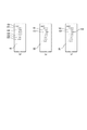
図1および図2は、本実施例に係る情報処理装置Aの構成を示している。図1に示すように、本実施例の情報処理装置Aは、例えばパソコン(パーソナルコンピュータ)Bに、ユーザーインターフェースとして表示装置Cと、操作入力部Dを装着して構成することができる。操作入力部Dには、マウスやトラックパッドその他のポインティングデバイス、およびキーボードなどの操作デバイスを用いることができる。 1 and 2 show the configuration of an information processing apparatus A according to the present embodiment. As shown in FIG. 1, an information processing apparatus A according to the present embodiment can be configured by, for example, mounting a display device C and an operation input unit D as a user interface on a personal computer (personal computer) B. As the operation input unit D, an operation device such as a mouse, a trackpad, or another pointing device, and a keyboard can be used.
表示装置Cは、LCD(あるいは他の表示方式によるディスプレイ装置)などの表示装置により構成される。表示装置Cは、その表示面にいわゆるタッチパネルを積層して構成することもできる。その場合には、操作入力部Dのポインティングデバイス、やキーボードなどの操作デバイスと同等の入力操作をタッチパネルにより行うことができ、場合によっては操作入力部Dを省略した構成とすることもできる。 The display device C includes a display device such as an LCD (or a display device using another display method). The display device C can also be configured by stacking a so-called touch panel on its display surface. In that case, an input operation equivalent to an operation device such as a pointing device or a keyboard of the operation input unit D can be performed by the touch panel. In some cases, the operation input unit D may be omitted.
本実施例の情報処理装置Aは、実際にロボット装置と接続してこれを動作させるようなオンライン環境よりも、主にオフライン環境でロボット装置の教示データの入力、編集、変更などに用いることができるよう構成される。本実施例の情報処理装置Aはロボット装置の教示データの入力、編集、変更の操作は、操作入力部Dによって行えるよう構成され、表示装置Cには、例えば図1に示すようなオフライン教示システムの表示画面Eを表示させることができる。 The information processing apparatus A of the present embodiment can be used mainly for inputting, editing, and changing the teaching data of the robot apparatus in an offline environment, rather than an online environment in which the robot apparatus is actually connected and operated. It is configured to be able to. The information processing apparatus A according to the present embodiment is configured such that the input, edit, and change operations of the teaching data of the robot apparatus can be performed by the operation input unit D, and the display apparatus C includes, for example, an offline teaching system as shown in FIG. Can be displayed.
図1の表示画面Eは、少なくとも仮想環境画面10、およびパラメータ設定画面20、および管理画面40を含む構成となっている。
The display screen E in FIG. 1 includes at least a
仮想環境画面10、パラメータ設定画面20、管理画面40はグラフィックユーザインターフェース(GUI)として構成することができる。その場合、操作入力部Dのマウスなどのポインティングデバイス(ないし上記のタッチパネル)により、表示画面Eを構成する表示オブジェクト(メニュー、数値や文字の入力フィールド、ロボットアームの仮想表示など)を操作できるよう構成される。このようなGUI環境の実装手法の細部は概ね公知であるため、ここでは詳細な説明は省略する。
The
仮想環境画面10(仮想環境表示部)には、本装置でプログラム(教示)する実機のロボット装置と同等の配置環境を再現した仮想環境を表示する。例えば、仮想環境画面10は、位置姿勢データにより特定されるロボット101装置の状態を3DCADモデルのような3Dモデル表現により仮想表示する。その場合、後述のCPU(33)の表示装置Cを制御する表示制御機能によって、例えば、ロボット101の作動環境に擬した仮想空間中に位置姿勢データにより特定される位置姿勢にあるロボット101の3D画像をレンダリングして仮想表示を行う。このように位置姿勢データからロボット101を3DCADモデル表現などにより仮想表示するための(画像)表示制御については公知であるから、ここでは詳細な説明は省略する。
The virtual environment screen 10 (virtual environment display unit) displays a virtual environment that reproduces an arrangement environment equivalent to that of a real robot device that is programmed (taught) by the present device. For example, the
図1の場合、仮想環境画面10には本装置でプログラム(教示)する実機のロボット装置に相当するロボット101と、ロボット101の先端に取り付けたツール102、ワーク103が配置され表示されている。本実施例では、ユーザ(作業者)がロボットプログラムや教示データ(位置姿勢データ)に対する入力、編集などを行った場合、その変更に応じて仮想環境画面10の仮想環境の表示を更新する。これにより、ユーザ(作業者)は、仮想環境画面10の仮想環境の表示を介して容易に入力や編集の内容を確認することができる。
In the case of FIG. 1, a
多くのロボット装置では、位置姿勢データの表現に座標データが用いられる。この座標データの表現には、いくつかの異なる座標系における座標データが用いられる。例えば、本装置で取り扱うロボット101では、ベース座標系104(絶対座標系100)、およびツール座標系105が用いられる。本実施例では、ロボット101のベース座標系104は、仮想環境の絶対座標系100と一致した位置に配置されている。また、ツール102の先端にはツール座標系105が存在している。これらの座標系は、3次元座標系であり、仮想環境画面10中では、必要に応じて図示のように3軸(X、Y、Z)の座標軸を表示することができる。
In many robot devices, coordinate data is used to represent position and orientation data. In expressing this coordinate data, coordinate data in several different coordinate systems are used. For example, in the
図1に例示した仮想環境画面10では、ワーク103の上空に基準となる教示点106が表示されている。この教示点106は、例えば既に入力済みの教示点である。ここで、例えばツール102を教示点106から下降させてワーク103に対してアプローチさせる動作を考える。
In the
この場合、例えば基準となる教示点106よりオフセットとなる相対値を用いて設定したオフセット教示点107をワーク103の上面に教示する手法が用いられる。この場合、教示点106に対して用いられるオフセットの相対値は、例えばZ軸方向の移動量(距離)などの数値によって表現される。なお、図1の仮想環境画面10では、ロボット101の位置姿勢は、その所定部位(例えばツール102の把持中心やツール装着面の中心など)が基準となる教示点106と一致した時の位置姿勢が表示されている。
In this case, for example, a method of teaching an offset
さらに、表示装置Cの表示画面E中には、パラメータ設定画面20を表示させている。本実施例においては、パラメータ設定画面20は、位置姿勢データの数値表示を行うパラメータ表示部の機能と、GUI操作によってその値を設定するパラメータ設定部の機能を兼ねている。このパラメータ設定画面20には、現在のロボット101の位置姿勢を表したパラメータが数値表現の形式でそれぞれの表示位置に表示されている。パラメータ設定画面20の各パラメータに相当する数値の表示位置は、例えば数値(文字)入力のためのいわゆる入力ボックスとして構成される。これらのパラメータの入力ボックスの数値(あるいは文字)は、操作入力部Dを操作することにより、新たに入力したり、既に入力されている値を変更したりすることができるよう構成される。なお、このような入力ボックスを用いたユーザーインターフェースを実現するためのハードウェアやソフトウェアの細部については公知であり、ここでは詳細な説明は省略する。
Further, a
ロボット装置(ロボット101)を制御する教示データ(教示点や位置姿勢データ数値データの実体)や、3Dモデル表現などにより仮想環境画面10中にモデリングないしレンダリングするためのモデル情報は、階層データの形式で格納、管理する。
Model data for modeling or rendering in the
記憶装置35のRAM35bや外部記憶装置35cは、複数の位置姿勢データを格納する記憶手段として用いられる。例えば、ロボット101の異なる部位がロボット装置の構造によって特定される特定の依存関係にある場合、異なる部位に対応する複数の位置姿勢データは記憶装置35に階層構造データとして記憶する。
The
この階層構造データの構造や内容については、例えば以下の管理画面40(管理表示部)の説明を通して理解されよう。 The structure and contents of the hierarchical structure data will be understood through the following description of the management screen 40 (management display unit), for example.
即ち、本実施例では、表示装置Cの表示画面E中には、教示データ(教示点や位置姿勢データ)やモデル情報のデータ構造を表示するための管理画面40(管理表示部)を表示させる。管理画面40には、仮想環境画面10で表示されているモデル情報と教示点情報が一括でノード管理され、その状態がいわゆる樹形図の形式で表示されている。
That is, in the present embodiment, a management screen 40 (management display unit) for displaying the data structure of the teaching data (teaching points and position and orientation data) and the model information is displayed on the display screen E of the display device C. . On the
本実施例における教示データやモデル情報に関するノード管理では、一番上の根のモデル情報を絶対座標系100(ROOT)とし、絶対座標系(100)から枝と階層構造で複数のモデル情報の関連を示すデータ構造を用いる。本実施例の位置姿勢データのデータ構造においては、根に近いモデルを親のモデル、葉に近いモデルを子のモデルと呼ぶ。 In the node management related to the teaching data and the model information in the present embodiment, the model information of the top root is defined as an absolute coordinate system 100 (ROOT), and the relation of a plurality of model information in a hierarchical structure with branches from the absolute coordinate system (100). Is used. In the data structure of the position and orientation data according to the present embodiment, a model close to the root is called a parent model, and a model close to a leaf is called a child model.
関連付けとして管理する情報は、親と子のモデル情報の関係性、親から子までのモデルの位置姿勢となる相対値情報を保有しているものとする。だたし、本実施例の教示データやモデル情報に関するノード管理で管理する情報は相対値情報に限定されない。例えば、根から子までのモデルの位置姿勢に相当する絶対値情報を格納するようにしても良い。 It is assumed that the information managed as the association has the relationship between the model information of the parent and the child and the relative value information indicating the position and orientation of the model from the parent to the child. However, the information managed in the node management regarding the teaching data and the model information in the present embodiment is not limited to the relative value information. For example, absolute value information corresponding to the position and orientation of the model from the root to the child may be stored.
本実施例における教示データやモデル情報を管理するための(階層)ノード形式のデータ格納形式には、各ノードのデータを例えばアドレスポインタなどを介して関係づけた上でメモリ中に格納する、例えばリンクトリストの形式などを利用できる。あるいは、教示データやモデル情報をHDDやSSDのような外部記憶装置上のファイルシステムに格納する場合には、各種リレーショナルデータベースシステムにおけるデータ格納形式を利用してもよい。 In the data storage format of the (hierarchical) node format for managing the teaching data and model information in the present embodiment, the data of each node is stored in a memory after being associated with each other via, for example, an address pointer. You can use the linked list format. Alternatively, when storing teaching data and model information in a file system on an external storage device such as an HDD or SSD, a data storage format in various relational database systems may be used.
なお、本明細書を通して、管理画面40の表示は、記憶装置35上に格納された教示データ(位置姿勢データ)のノードから成る階層的なツリー構造を視覚的に表示したものとして取り扱う。また、同時に管理画面40の図示は、記憶装置35上に格納された上記ツリー構造の教示データ(位置姿勢データ)のメモリマップ表示と考えてもよい。
Throughout this specification, the display of the
上記のようなノード管理によれば、親のモデルの位置姿勢となる相対値情報を変更した場合、子のモデルは、親から子までのモデルの位置姿勢に相当する相対値情報を保有しているため、親のモデルに従って追従することができる。 According to the node management described above, when the relative value information serving as the position and orientation of the parent model is changed, the child model holds relative value information corresponding to the position and orientation of the model from the parent to the child. Therefore, it can follow the parent's model.
図1の管理画面40に表示しているデータ構造では、絶対座標系100(ROOT)の子のモデル情報の下位にロボット101(ROBOT)とワーク103(Work)が位置している。さらに、ロボット101の子のモデル情報に、ツール102(Tool)と、ツール座標系105(TCP)が位置している。さらに、ロボット101の子のモデルには教示点が関連づけられる。例えばロボット101の子のモデルの1つとして、基準となる教示点106(P001)が関連づけられている。さらに、基準となる教示点106の子のモデルには、オフセット教示点107(P100)が関連づけられている。
In the data structure displayed on the
次に、図1の情報処理装置Aのパソコン(パーソナルコンピュータ)Bにより構成された制御系の構成を図2に示す。図2に示すように、図1の情報処理装置Aを構成するパソコンBは、ハードウェア的には、CPU33と、ROM35a、RAM35b、外部記憶装置35cなどから成る記憶装置35を含む。さらに、パソコンBは、操作入力部Dと接続するためのインターフェース32a、表示装置Cと接続するためのインターフェース32b、外部装置と例えばファイルFの形式でデータを送受信するためのインターフェース36を含む。これらのインターフェースは、例えば各種シリアルバスやパラレルバス、ネットワークインターフェースなどから構成される。
Next, FIG. 2 shows a configuration of a control system constituted by a personal computer (personal computer) B of the information processing apparatus A of FIG. As shown in FIG. 2, a personal computer B constituting the information processing apparatus A of FIG. 1 includes a
図2では、CPU33とともに計算部34が示してあるが、この計算部34は、実際にはCPU33が後述の制御演算を行うための制御プログラムを実行することにより実現される。表示装置Cには、上述の仮想環境画面10やパラメータ設定画面20、管理画面40などから構成されるGUI形式の表示画面Eを表示する。操作入力部Dは、表示装置Cの表示画面EとともにGUI(グラフィカルユーザーインターフェース)を構成し、操作入力部DのポインティングデバイスやキーボードによるユーザのGUI操作を受けつける。
In FIG. 2, the
CPU33は情報処理装置A全体のシステム制御を行う。CPU33は、操作入力部Dで行われた入力、編集操作に基づき、計算部34の制御演算を行う。この計算部34の制御演算によって、表示装置Cの表示を更新するための表示制御情報が生成されるとともに、記憶装置35に格納された教示データおよびモデル情報の更新を行う。
The
記憶装置35は、仮想環境画面10に表示されている3DCADモデル情報や配置環境情報、教示データなどを格納する。特に、教示データやモデル情報は、上記の(階層)ノード形式で格納される。記憶装置35に格納された各種データは、CPU33からの要求に応じて出力され、また、CPU33からの要求に応じて更新される。
The
また、外部装置からの要求、あるいは操作入力部Dにおける特定の操作に応じて、CPU33は記憶装置35に保存された各種データをファイルFの形式でインターフェース36から送信させることができる。また、インターフェース36を介して外部からファイルFを必要に応じて読み込むこともできる。例えば、情報処理装置Aの起動時やレストア(復元)処理では、外部装置(例えば外部のHDD、SDD、NASなどの外部記憶装置)から過去に出力したファイルFを読込み、記憶装置35を更新し、以前の記憶の状態を再現することができる。
Further, in response to a request from an external device or a specific operation on the operation input unit D, the
なお、本実施例において、ロボット101の教示データやモデル情報を格納する記憶装置35の記憶領域は任意であり、例えばRAM35b上の所定領域や、外部記憶装置35cの(例えば所定ファイルに対応する)記憶領域を用いることができる。
In the present embodiment, the storage area of the
以上が、情報処理装置Aの全体構成の一例である。なお、以上では、例えばオフライン教示に適したシステムの例として、パソコンBのようなハードウェア構成を例示した。しかしながら、情報処理装置Aはオフライン教示システムに限定されることなく、ロボット装置とともに現場に設置されるティーチングペンダントなどのハードウェア構成であっても構わない。その場合、ティーチングペンダントの表示装置が上述と同等の仮想環境画面を表示できるよう構成されていれば、本実施例と同等の構成を実施することができる。 The above is an example of the overall configuration of the information processing apparatus A. In the above, for example, a hardware configuration such as a personal computer B has been illustrated as an example of a system suitable for offline teaching. However, the information processing apparatus A is not limited to the off-line teaching system, and may have a hardware configuration such as a teaching pendant installed on the site together with the robot apparatus. In this case, if the display device of the teaching pendant is configured to display a virtual environment screen equivalent to the above, the same configuration as that of the present embodiment can be implemented.
次に、本実施例における作成および編集処理の一例として、上記構成におけるオフセット教示点107の作成および編集処理を説明する。オフセット教示点107の作成・編集処理については、操作入力部Dおよび表示装置CのGUIで行われた操作に応じて異なる処理と表示を行う。
Next, as an example of the creation and editing processing in the present embodiment, the creation and editing processing of the offset
例えば、この種の情報処理装置Aでは、図1のオフセット教示点107に関しては、位置姿勢データを異なる座標系における座標値を用いた入力ないし編集に対応できる必要がある。また、一旦、位置姿勢データを入力された後、ユーザがパラメータ表示に用いる座標系を切り替えた場合や、ユーザが元の基準となる教示点106の位置姿勢データを編集した場合にも対応できる必要がある。
For example, in this type of information processing apparatus A, it is necessary for the offset
そこで、以下では、オフセット教示点107の作成・編集処理については、次の4つのケースについて説明する。これらは、「ツール座標系105を選択した場合」、「ベース座標系104を選択した場合」、「座標系を切り替えた場合」、「基準となる教示点106を編集した場合」の作成・編集処理である。
Therefore, in the following, the following four cases will be described as to the creation / edit processing of the offset
(ツール座標系を用いたオフセット教示点の作成)
まず、1つ目のケース、ツール座標系105を選択してオフセット教示点107の作成手順と処理につき、図3から図5、図7から図8を参照して説明する。この例では、基準となる教示点106よりZ軸方向に「30mm」オフセットしたオフセット教示点107を作成する。
(Creating offset teaching points using the tool coordinate system)
First, the first case, a procedure and a process for creating the offset
図3は、オフセット教示点107を新規作成した場合のCPU33が実行する制御手順の流れを示している。図示の手順はCPU33が実行可能なプログラムの形式で、例えば記憶装置35のROM35aや外部記憶装置35cに格納しておくことができる。この点については、後述の他のフローチャート図に示した制御手順でも同様である。
FIG. 3 shows a flow of a control procedure executed by the
なお、ROM35aは、後述のような情報処理プログラムを記憶するための、コンピュータ(CPU33)により読み取り可能な記録媒体に相当する。CPU33は、例えばROM35aに格納された情報処理プログラムを実行することにより、後述のようなトルク制御を含むロボット制御を実行する。なお、ROM35aの一部は、E(E)PROMのような書き換え可能な不揮発領域により構成できる。その場合、当該の不揮発領域を不図示のフラッシュメモリや光ディスクのようなコンピュータ読み取り可能なメモリデバイス(記録媒体)で構成することもでき、例えばそのメモリデバイスの交換により情報処理プログラムのインストールや更新が可能である。また、ネットワークなどを介して取得した情報処理プログラムを新たに上記書き換え可能な不揮発領域にインストールすることもできる。また、上記書き換え可能な不揮発領域に格納されている情報処理プログラムは、上記コンピュータ読み取り可能な記録媒体や、ネットワークなどを介して取得したデータによって更新することもできる。
The
図4(a)〜(d)はオフセット教示点107の作成・編集処理に係わるロボット101の仮想環境画面10における表示状態を示している。図1では前方からの斜視図のような表示であるが、図4(a)〜(d)の仮想環境画面10の表示では理解を容易にするため、側方からの表示を採用している。
4A to 4D show display states on the
図4(a)は、ロボット101の初期姿勢であり、図3のオフセット教示点107の作成を行う処理の開始時の位置姿勢を示している。なお、基準となる教示点106は、例えばロボット101のベース座標系104からの相対値により表現された教示点であり、ここでは既に作成されている状態とする。
FIG. 4A shows the initial posture of the
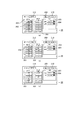
また、図5(a)〜(d)(後述の図6(a)〜(d)も同様)は、オフセット教示点107の作成・編集処理中のGUI、特にパラメータ設定画面20における入力、表示の状態を示している。
FIGS. 5A to 5D (the same applies to FIGS. 6A to 6D to be described later) show a GUI during the creation / editing process of the offset
図3の処理手順において、ステップS0では、操作入力部Dで所定の操作を行い、新規にオフセット教示点107を作成する処理を指定する。このオフセット教示点(107)の作成では、図5(a)〜(d)に示すようなパラメータ設定画面20が用いられる。
In the processing procedure of FIG. 3, in step S0, a predetermined operation is performed by the operation input unit D, and a process of newly creating the offset
図5(a)〜(d)のパラメータ設定画面20では、絶対値設定部201と、相対値設定部202と、教示点設定部203と、座標系選択部204を表示している。図5(a)の初期状態では、新規にオフセット教示点を作成する操作をまだ行っておらず、まだパラメータは何も入力されていない。
5A to 5D, an absolute
絶対値設定部201は、例えば絶対座標系(例えばベース座標系104)における絶対座標値の入力に用いられる。また、相対値設定部202は、例えば相対座標系(例えばツール座標系105)における相対座標値の入力に用いられる。座標系選択部204は、パラメータ設定画面20で位置姿勢データに対応する座標値を表示する場合に用いる座標系としてロボット101に関して用いられる異なる座標系の1つを指定するための座標系指定手段を構成する。
The absolute
オフセット教示点の新規作成では、基準となる教示点(106)を設定する必要がある。基準となる教示点106を設定する(教示点設定手段、図3のステップS1)場合、図5(a)のようにして、基準となる教示点106の設定操作を行う。
When a new offset teaching point is created, it is necessary to set a reference teaching point (106). In the case of setting the reference teaching point 106 (teaching point setting means, step S1 in FIG. 3), the setting operation of the
例えば、ユーザは図5(a)の教示点設定部203を操作入力部Dのマウスのカーソル205でクリックする。これに応じて、CPU33は、表示装置Cを制御して、パラメータ設定画面20の教示点設定部203を例えばプルダウンメニューのように用いて選択可能な教示点リスト206を表示させる。ユーザ(作業者)は、この教示点リスト206より、基準となる教示点106をマウスクリックなどにより選択することができる。
For example, the user clicks the teaching
このようにして基準となる教示点106の選択が完了すると、CPU33は記憶装置35に記録された選択した教示点「P001」のパラメータを読み出し、読み出したパラメータに基づき表示装置Cの表示画面Eを更新する。具体的には、教示点リスト206の「基準」の表示を、図5(b)のように教示点「P001」に対応する表示に切り替える。
When the selection of the
また、この時、同時に表示装置Cの仮想環境画面10の表示も例えば図4(b)のように更新することができる。図4(b)は、更新後の表示装置Cの仮想環境画面10に表示されているロボット101の位置姿勢を側方から示している。図4(b)の仮想環境画面10では、ロボット101のアームの基準部位が(基準)教示点106と一致する位置姿勢を表示している。
At this time, the display of the
本実施例では、新規のオフセット教示点107を入力するために任意の座標系を選択することができる(座標系選択手段、ステップS2)。 In this embodiment, an arbitrary coordinate system can be selected for inputting a new offset teaching point 107 (coordinate system selecting means, step S2).
例えば、ユーザは図5(b)に示すように、座標系選択部204をマウスのカーソル205でクリックする。これに応じて、CPU33は、表示装置Cを制御して、パラメータ設定画面20の座標系選択部204を例えばプルダウンメニューのように用いて選択可能な座標系リスト207を表示させる。ユーザ(作業者)は、この座標系選択部204に表示される座標系リスト207にある座標系を選択することができる。ここで、ユーザは座標系リスト207から、例えばツール座標系105を選択する。
For example, as shown in FIG. 5B, the user clicks the coordinate
図5(a)〜(d)に示すように、パラメータ設定画面20(の左側)には絶対値設定部201、相対値設定部202を表示する。ユーザは、これら絶対値設定部201、相対値設定部202を用い、上記のようにして指定した教示点に関して、指定した座標系における位置姿勢データを数値入力することができる。位置姿勢データとしては、絶対値設定部201、相対値設定部202は、例えば、X、Y、Z、α、β、γで示すように3次元座標値と軸廻りの回転角により指定することができる。このうち、座標値の単位は例えばmm、また、軸廻りの回転角には、例えばオイラー角ZYX(αβγ)表現を用いる。
As shown in FIGS. 5A to 5D, an absolute
この段階で、ユーザは新規のオフセット教示点107のオフセットとなる相対値を設定することができる(パラメータ設定手段、ステップS3)。 At this stage, the user can set a relative value to be the offset of the new offset teaching point 107 (parameter setting means, step S3).
絶対値設定部201、相対値設定部202の上部は、作成する教示点名を入力・表示する教示点名設定部212となっている。ここで、ユーザは、教示点名設定部212に所望の教示点名(例えば図5の例では「P100」)を入力する。また、この段階で、教示点名設定部212にはCPU33が自動的に生成した教示点名を入力済みの状態で表示するようにしてもよい。
Above the absolute
また、新規のオフセット教示点107の入力において、相対値設定部202の全てのフィールドの初期状態は0(図5(b))で、この時、絶対値設定部201には、例えば基準となる教示点106の位置姿勢データと同じ値(コピー)を表示することができる。
When a new offset
また、この段階では、前述のようにして図4(b)のようにアームの基準部位が(基準)教示点106と一致した状態となっており、教示点106(P001)に対するオフセットの指定には、例えばツール座標系105を用いることができる。そこで、ここでは、(上記のように指定済みの)ツール座標系105を用いて、Z軸方向に前述の「30mm」のオフセットするオフセット教示点107を指定し、作成する。
Further, at this stage, as described above, the reference portion of the arm coincides with the (reference)
ユーザは、例えば、図5(c)のように操作入力部Dのマウスを用いて相対値設定部202のZ座標値のフィールドに対応する設定欄208を選択し、操作入力部Dのキーボードから「30」の値を入力し、同キーボードの[Enter]キーを押下する。
The user selects the setting
CPU33は、相対値設定部202への数値入力に応じて、記憶装置35の例えばRAMなどに配置された相対値設定部202に対応するメモリ領域の内容を更新する。即ち、操作入力部Dで位置姿勢データの一部を変更する操作入力が行われると、操作入力の内容に応じて当該の一部の位置姿勢データを変更する(第1の演算工程)。
The
操作入力部Dのキーボードで[Enter]キーを押下すると、CPU33のソフトウェアにより構成された計算部34の位置姿勢演算が開始される(姿勢計算手段)。
When the [Enter] key is pressed on the keyboard of the operation input unit D, the position and orientation calculation of the
ここでは、まず、オフセット教示点107に関して選択されている座標系がツール座標系105か判断する(図3ステップS4)。ここで選択されている座標系がツール座標系105の場合、ステップS5に進み、ツール座標系105の姿勢計算処理を実行する(関節値計算処理、ステップS5)。
Here, first, it is determined whether the coordinate system selected for the offset
なお、ここで関節値とは、ロボット101のある関節の曲げ(回転)角度などにより表現され、その関節の位置(または姿勢)を特定する関節データである。このような関節データは、本実施例においては、後述の制約エラーのチェックなどのために演算の途中で利用されるが、明示的に位置姿勢データの一部として関節データを直接、入力、編集する例については、後述の実施例5で説明する。
Here, the joint value is expressed by a bending (rotation) angle of a joint of the
ここで、ツール座標系105を選択している場合の計算は、以下の式(1)のように行う(座標変換)。ここでは、基準となる教示点106の相対値の姿勢行列T1と、オフセットとなる相対値の姿勢行列T2の積より、ロボット101のベース座標系104からオフセット教示点107までの相対値の姿勢行列T3を計算する。
Here, the calculation when the tool coordinate

ここで姿勢行列Tは、次式(2)の如く4行4列の行列とし、1行・1列から3行・3列までのパラメータを回転行列R、1行から3行までの4列目を位置行列P、4行・1列から4行・3列までを0行列、4行・4列を1としたものである。 Here, the attitude matrix T is a matrix of 4 rows and 4 columns as in the following equation (2), and the parameters from 1 row / 1 column to 3 rows / 3 columns are the rotation matrix R, and 4 columns from 1 row to 3 rows. The eye is a position matrix P, from 4 rows / 1 column to 4 rows / 3 columns is 0 matrix, and 4 rows / 4 columns is 1.
そして、式(1)の計算結果より逆運動学計算を行い、ロボット101の各軸の関節値を計算する。即ち、ステップS5(あるいは後述のS6)において、CPU33は、上記第1の演算工程において変更された一部の(オフセット教示点107の)位置姿勢データに基づき、ロボット装置の各部位の位置または姿勢をそれぞれ特定する位置姿勢演算を行う。この位置姿勢演算の結果に基づき新たな位置姿勢データ(例えば関節値)を求める(第2の演算工程)。
Then, an inverse kinematics calculation is performed based on the calculation result of Expression (1), and a joint value of each axis of the
さらに、CPU33は、逆運動学計算結果より表示装置Cの表示画面Eの表示を更新する(図3ステップS7〜S9)。即ち、CPU33は、第1の演算工程において変更された一部の位置姿勢データ、および第2の演算工程において計算された新たな位置姿勢データに基づき、表示装置Cの表示画面Eの表示を更新する(表示更新工程)。
Further, the
表示装置Cの表示画面Eの表示を更新では、例えば、表示装置Cの管理画面40、仮想環境画面10の仮想表示、ないしパラメータ設定画面20の数値表示の内容を更新する。なお、この表示装置Cの表示画面Eの更新に先立ち、第2の演算工程で算出した位置姿勢データに相当する各関節値が実機のロボット101のハードウェア仕様などにより定まる制約内か否かのエラーチェックを行う(下記のステップS7)。
In updating the display of the display screen E of the display device C, for example, the contents of the
ステップS7では、オフセット教示点107の各関節値が実機のロボット101のハードウェアの仕様(あるいはさらに運用上の規約)などにより定まる制約内か判断する(制約判断処理)。例えば、実機のロボット装置では、ある関節が取り得る回転角の範囲が特定の範囲に制約されている場合があり、このような制約の範囲内にロボット101の各関節値が収まっているか否かを判定する。このようなロボット101の可動範囲などの制約の条件は、適当な格納形式で予めROM35a、RAM35bや外部記憶装置35cなどに格納されているものとする。
In step S7, it is determined whether or not each joint value of the offset
ステップS7の判定の結果が制約内であれば、CPU33は表示装置Cの表示画面Eを更新する(正常系表示処理、S9)。ここでは、仮想環境画面10のロボット101の表示と、パラメータ設定画面20の内容を更新する。ここで、ロボット101のベース座標系104は、前述のように絶対座標系100と一致している。そのため、更新内容は、ベース座標系104からのオフセット教示点107までの相対値を絶対値設定部201に、逆運動学計算によるロボット101の各軸の関節値の計算結果を仮想環境画面10に反映させて更新する。
If the result of the determination in step S7 is within the constraint, the
さらに、この表示装置Cの表示画面Eの更新では、変更箇所、非変更箇所を含め、GUI全体(仮想環境画面10、パラメータ設定画面20あるいはさらに管理画面40)を更新する。その結果、例えばパラメータ設定画面20は図4(c)のように更新される。
Further, in updating the display screen E of the display device C, the entire GUI (the
図4(c)は、更新後の表示装置Cの仮想環境画面10のロボット101の表示を示している。図4(b)と比較して明らかなように、図4(c)ではロボット101の表示はアームの基準部位がオフセット教示点107に位置する位置姿勢に変更されている。図4(c)において、d30として示されているのは、上記の30mmのオフセット量である。
FIG. 4C shows the display of the
また、図5(d)は、更新後の表示装置Cの表示画面Eのパラメータ設定画面20の表示を示している。ステップS7でエラーが起きていなければ、同図のようにオフセット教示点107のパラメータが更新される。
FIG. 5D shows a display of the
以上のように、操作入力部Dを用いて相対値設定部202に入力を行うと、直ちに仮想環境画面10のロボット101の表示と、パラメータ設定画面20の表示が更新され、新規のオフセット教示点107における位置姿勢とパラメータを確認できる。
As described above, when an input is made to the relative
従って、ユーザ(作業者)は実際にロボット装置が情報処理装置Aに接続されていなくても、あるいはその実機のロボット装置を動作させなくても、表示装置Cの表示画面Eを視認するだけで入力(編集)操作の妥当性を確認することができる。これにより、従来必要であった入力(編集)操作の妥当性の確認に必要な工数の削減を図ることが出来る。 Therefore, even if the user (operator) does not actually connect the robot apparatus to the information processing apparatus A, or does not operate the actual robot apparatus, the user (worker) only needs to visually recognize the display screen E of the display apparatus C. The validity of the input (edit) operation can be confirmed. As a result, it is possible to reduce the man-hour required for confirming the validity of the input (editing) operation, which has been required conventionally.
一方、ステップS7において、位置姿勢演算の結果、例えば各関節値のいずれかがハードウェア的な制約を外れている場合、CPU33は表示装置Cで姿勢が取れないというエラーを表示させる(異常表示処理、S8)。例えばこの時、表示させるエラー画面50は、図8のようなものが考えられる。図8のエラー画面50は、到達姿勢がリミットの制約外にあり、エラーが発生していることを文字列および図形のシンボルによって表示している。
On the other hand, in step S7, as a result of the position and orientation calculation, for example, if any of the joint values is out of the hardware restrictions, the
この画面を表示する場合は、CPU33はパラメータ設定画面20のオフセット教示点107の数値をクリアし、相対値入力前(例えば図5(a)または(b))の状態に戻す。その後、図3の制御の場合はステップS3の相対値の編集(入力)操作に戻るため、上記同様にしてオフセット教示点107の入力値を変更するなどの作業を行うことができる。
When displaying this screen, the
即ち、CPU33は、前記第2の演算工程における計算の結果、得られた位置姿勢データがロボット101の機構の制約の範囲内にあるか否かを判定する。もし、当該の位置姿勢データが前記ロボット装置の機構の制約の範囲内を超える場合、編集エラーを報知するエラー情報(例えばエラー画面50)を生成する。
That is, the
続いて、仮想環境画面10のロボット101の表示と、パラメータ設定画面20の表示を視認したユーザは目的の到達姿勢かどうかを確認する操作を行う(ステップS10)。ステップS10において、オフセット教示点107が目的の到達姿勢の場合、マウスのカーソルで確定ボタン209を選択し、クリックする確認操作を行う。この確認操作によってオフセット教示点107の作成が完了する。これにより、CPU33は、確定されたオフセット教示点107の情報を記憶装置35に格納する。
Subsequently, the user who has visually recognized the display of the
以上のようにして、新規のオフセット教示点107の作成が終了する(記録手段、図3のステップS11)。なお、記憶装置35に記録する情報としては、例えば、基準となる教示点106の情報、選択した座標系の情報、オフセット情報の3つの情報をオフセット教示点107の(に関する)情報とし、この情報を記憶装置35に記録する。あるいはさらに、この教示点の情報が相対的な「オフセット」情報であることを示すデータクラスなどに係るタグ情報を含めて記憶装置35に格納してもよい。このような格納形式によれば、オフセット教示点107が教示点106を基準として定義されている、即ち、教示点107が教示点106の下位に従属するデータであることを特定できる。
As described above, the creation of the new offset
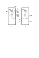
なお、新規のオフセット教示点107の作成に関しては、CPU33の制御によって管理画面40の表示も更新することができる。ここで、図7(a)、(b)は、それぞれオフセット教示点107の作成前、およびオフセット教示点107の作成完了後の管理画面40の表示状態を示している。図7(a)ではロボット101のツリーには、P001、P010、P020の各々の教示点106のノード、TCP(105)およびTool(102)のノードが階層化されている。
Note that the display of the
そして、上記のようにして新規のオフセット教示点107を正常に作成すると、ノードの管理画面40の基準となる教示点106の下位に新規のオフセット教示点107のノードが新たに作成されている。このように基準となる教示点106の下位に新規のオフセット教示点107のノードを表示する。これにより、ユーザはオフセット教示点107が親である教示点106のノードに子として従属する関係を有する(オフセット)教示点であることを極めて明確に認識することができる。
Then, when the new offset
なお、図7の管理画面40の各ノードは、当該のノードを選択するGUI上のボタン(やアイコン)として用いることができる。例えば、管理画面40の各ノードをマウスなどを用いてクリックした場合、CPU33は、そのノードの(位置姿勢)データの編集操作が指定されたものと判定する。例えば、オフセット教示点107の編集を行う場合には、管理画面40のオフセット教示点107をマウスのカーソルでクリックすることにより、ユーザは同教示点の(再)編集を開始することができる。
Each node on the
なお、記憶装置35に格納した位置姿勢データは、ツリーの全体(例えば図7のツリーの全体)、または操作入力部Dで指定した特定の一部などを単位としてファイルFの形式でインターフェース36を介して外部装置に出力することができる(入出力手段)。
The position and orientation data stored in the
このようにして出力したファイルFは、後日、インターフェース36で読み込むことができる。これにより、ファイルFから例えばツリーの全体(例えば図7のツリーの全体)を読み込んだ場合には、ファイルFの位置姿勢データを作成した時のシステムの状態を復旧することができる。例えば、ファイルFの読み込みに応じて、CPU33は図7(b)の管理画面40を表示し、例えばそこからオフセット教示点107を選択すると、図4(c)、図5(d)の状態を再現できる。
The file F thus output can be read by the
また、ファイルFを、実機のロボット装置のコントローラと共有フォーマットに整え(変換し)てインターフェース36から出力することもできる。これにより、情報処理装置Aで作成した教示データを直接、実機のロボット装置に入力することができる。
Further, the file F can be prepared (converted) into a format shared with the controller of the actual robot apparatus and output from the
ここで、例えば、実機のロボット装置のコントローラのインターフェースが動作プログラムとオフセット変数で構成されている場合がある。このような場合には、CPU33は、ファイルFを介して、基準となる教示点106の情報は教示点情報として出力させ、オフセット教示点107の情報は動作プログラムのオフセット編集情報として出力させるような形態が考えられる。
Here, for example, the interface of the controller of the actual robot device may be composed of an operation program and offset variables. In such a case, the
また、実機のロボット装置のコントローラの教示点情報のインターフェースがロボットのベース座標系104からの相対値情報のみを用いる構成も考えられる。このような場合には、CPU33がオフセット教示点107と基準となる教示点106の積を計算し、全ての教示点情報をロボットのベース座標系104からの相対値に変換してからファイルFを介して出力することができる。
Further, a configuration in which the interface of the teaching point information of the controller of the actual robot device uses only the relative value information from the base coordinate
以上のように、インターフェース36およびファイルFを介して行う外部機器、特に実機のロボット装置とのデータの入出力の際、必要なフォーマット変換を行うことにより、様々な実機のロボット装置(あるいはコントローラ)に対応することができる。
As described above, when data is input / output to / from an external device, particularly, a real robot device through the
なお、オフセット教示点107の作成を止める場合は、図5(a)〜(d)のパラメータ設定画面20右上部のキャンセルボタン210をマウスのカーソルなどによってクリックする。このキャンセルボタン210をクリックすると、CPU33はオフセット教示点107に関する情報を削除し、オフセット教示点107作成前の状態に表示装置Cの表示画面Eを更新する。
When the creation of the offset
以上のようにして、新規のオフセット教示点107を作成することができる。
As described above, a new offset
(ベース座標系を用いたオフセット教示点の作成)
次に、2つ目のケース、基準となる教示点106よりベース座標系104を選択し、Z軸方向に「−30mm」オフセットを行うオフセット教示点107の作成手順と処理について図6(a)〜(d)を用いて説明する。図6(a)〜(d)は、図5(a)〜(d)と同等の様式でパラメータ設定画面20のGUIの遷移を示している。なお、ベース座標系104を用いる場合の制御手順については、前述の図3の一部に記述されている。
(Creating offset teaching points using the base coordinate system)
Next, in the second case, the base coordinate
図6(a)は、基準となる教示点106の設定操作で、基準となる教示点106を前述の図5(a)と同様に教示点設定部203を例えばプルダウンメニューのように用いて選択する(教示点設定手段、図3のステップS1)。
FIG. 6A shows a setting operation of the
次に、ベース座標系104を選択する(座標系選択手段、ステップS2)。図6(b)は、座標系の選択操作を示しており、ここでは前述の図5(b)と同様に座標系選択部204を例えばプルダウンメニューのように用いてベース座標系104を選択する(座標系選択手段、ステップS2)。
Next, the base coordinate
このようにして、基準となる教示点106の選択と、入力に用いる座標系(ベース座標系104)の選択が終了し、オフセット教示点107のオフセットとなる相対値設定に必要な準備が完了する。
Thus, the selection of the
次に、オフセットとなる相対値を設定する(パラメータ設定手段、S3)。図6(c)は、相対値設定部202の設定欄208へ設定する状況を示している。ここでは、相対値設定部202のZ軸の設定欄208をマウスのカーソルでクリックする。相対値設定部202のZ軸の設定欄208に操作入力部Dで操作しているキーボードで「−30」という数値を入力し、[Enter]キーを押下する。
Next, a relative value serving as an offset is set (parameter setting means, S3). FIG. 6C shows a situation where the relative value is set in the
なお、このオフセット入力値は、上述のツール座標系を用いた下方30mmのオフセット入力の例と等価である。オフセット「30」の符号が異なっているのは、入力に用いる座標系が前述の例ではツール座標系が用いられ、この例ではベース座標系が用いられていることによる。即ち、前述の例で30(mm)とプラスの値を入力しているのは、前述のツール座標系では、通常、ツール前方がZ軸の正方向に取られているためである。また、この例で−30(mm)とマイナスの値を入力しているのは、ベース座標系では、(図4の上方)Z軸の正方向であるため、下方へのオフセットが負値となるためである。 Note that this offset input value is equivalent to the above-described example of the offset input of 30 mm below using the tool coordinate system. The reason why the sign of the offset “30” is different is that the coordinate system used for input uses the tool coordinate system in the above-described example, and uses the base coordinate system in this example. That is, the reason why a positive value of 30 (mm) is input in the above-described example is that the front of the tool is usually taken in the positive direction of the Z-axis in the aforementioned tool coordinate system. In this example, a negative value of -30 (mm) is input in the positive direction of the Z-axis (upward in FIG. 4) in the base coordinate system. It is because it becomes.
CPU33は、相対値設定部202への数値入力に応じて、記憶装置35の例えばRAMなどに配置された相対値設定部202に対応するメモリ領域の内容を更新する。即ち、操作入力部Dで位置姿勢データの一部を変更する操作入力が行われると、操作入力の内容に応じて当該の一部の位置姿勢データを変更する(第1の演算工程)。
The
続いて、ユーザが操作入力部Dのキーボードで[Enter]キーを押下すると、CPU33は計算部34の機能によって位置姿勢演算を実行する(姿勢計算手段)。
Subsequently, when the user presses the [Enter] key on the keyboard of the operation input unit D, the
ここでは、まず、選択された座標系がツール座標系105か判断する(図3のステップS4)。この例では、選択されているのはベース座標系104であるからステップS4からS6に進み、ベース座標系104の位置姿勢演算を行う(ステップS6)。
Here, first, it is determined whether the selected coordinate system is the tool coordinate system 105 (step S4 in FIG. 3). In this example, since it is the base coordinate
例えば、ベース座標系104の位置姿勢演算の場合、姿勢行列を位置行列と回転行列に分けて計算を行い、最後に計算結果の積を求める手順で計算を行う。
For example, in the case of calculating the position and orientation of the base coordinate
まず、ロボット101のベース座標系104から基準となる教示点106までの相対値の姿勢行列T1と、オフセット教示点107のオフセットとなる相対値の姿勢行列T2の位置行列の和を計算し、姿勢行列Ttmp1を作成する(下記の式(3))。なお、この時の回転行列Rtmp1を0とする。
First, the attitude matrix T 1 of the relative value to the
次に、オフセット教示点107のオフセットとなる相対値の姿勢行列T2より、位置行列P2を0とした姿勢行列Ttmp2を作成する(下記の式(4))。
Then, from the attitude matrix T 2 of the relative values as the offset of the offset
次に、ロボット101のベース座標系104から基準となる教示点106までの相対値の姿勢行列T1より、位置行列P1を0とした姿勢行列Ttmp3を作成する(下記の式(5))。
Then, from the attitude matrix T 1 of the relative value to the
次に、式(3)、(4)、(5)の積より、ロボット101のベース座標系104からオフセット教示点107までの相対値の姿勢行列T3を計算する(下記の式(6))。
Then, equation (3), (4), than the product of (5), calculates the posture matrix T 3 relative values from the base coordinate
さらに式(6)の計算結果より逆運動学計算を行い、ロボット101の各軸の関節値を計算する。即ち、ステップS6において、CPU33は、上記第1の演算工程において変更された一部の(オフセット教示点107の)位置姿勢データに基づき、ロボット装置の各部位の位置または姿勢をそれぞれ特定する位置姿勢演算を行う。この位置姿勢演算の結果に基づき新たな位置姿勢データ(例えば関節値)を求める(第2の演算工程)。
Further, inverse kinematics calculation is performed based on the calculation result of Expression (6), and joint values of each axis of the
以上の位置姿勢演算によって、ベース座標系104を選択した場合のオフセット教示点107を求めることができる。
The offset
図3の制御において、続くステップS7からS11の制約範囲内か否かの判定は、前述のツール座標系105を用いたオフセット教示点107の入力の場合と同様に実行される。制約範囲内か否かの判定に関するエラー処理(例えば図8のメッセージ表示:ステップS8)は前述と同様に実施することができる。
In the control of FIG. 3, the determination as to whether or not the position is within the restriction range of subsequent steps S7 to S11 is executed in the same manner as in the case of inputting the offset
上記のベース座標系における位置姿勢演算(ステップS6)の後、エラーが発生していなければ、図3のステップS9において、表示装置Cの仮想環境画面10、パラメータ設定画面20あるいはさらに管理画面40の表示を更新する。この時の様子は、前述のツール座標系を用いる場合に説明した図4(b)〜(c)、図5(c)、あるいは図7(a)、(b)などと同様である。また、ステップS10のユーザによる確認と、S11の確定操作も前述のツール座標系を用いる場合と同様である(図5(d))。
After the position and orientation calculation in the base coordinate system (step S6), if no error has occurred, the
即ち、CPU33は、第1の演算工程において変更された一部の位置姿勢データ、および第2の演算工程において計算された新たな位置姿勢データに基づき、表示装置Cの表示画面Eの表示を更新する(表示更新工程)。
That is, the
以上のようにして、ベース座標系104を選択して、オフセット教示点107を作成することができる。そして、オフセット教示点107を作成すると同時に、表示装置Cの仮想環境画面10、パラメータ設定画面20あるいはさらに管理画面40の表示が更新されるため、新規のオフセット教示点107における位置姿勢とパラメータを確認できる。
As described above, the offset
従って、ユーザ(作業者)は実際にロボット装置が情報処理装置Aに接続されていなくても、あるいはその実機のロボット装置を動作させなくても、表示装置Cの表示画面Eを視認するだけで入力(編集)操作の妥当性を確認することができる。これにより、従来必要であった入力(編集)操作の妥当性の確認に必要な工数の削減を図ることが出来る。 Therefore, even if the user (operator) does not actually connect the robot apparatus to the information processing apparatus A, or does not operate the actual robot apparatus, the user (worker) only needs to visually recognize the display screen E of the display apparatus C. The validity of the input (edit) operation can be confirmed. As a result, it is possible to reduce the man-hour required for confirming the validity of the input (editing) operation, which has been required conventionally.
(オフセット教示点107の編集と座標系の切り替え)
次に、3つ目のケース、作成したオフセット教示点107を編集して座標系の切り替えた場合の制御につき図9を用いて説明する。図9は、入力済みのオフセット教示点107の座標系を切り替えた場合の制御手順を示している。
(Edit offset
Next, control in the third case, in which the created offset
従来では、座標系を切り替える必要が生じた場合、作業者(ユーザ)が行列計算を行い、パラメータを計算していたが、計算した数値の入力ミスなど、人為的なミスが発生することがあった。そこで、本例に示すように、座標系を切り替えた際に自動的に切り替えた座標系方向の相対値パラメータを計算する構成によれば、このような人為的な計算ミスを低減させることができる。以下、ベース座標系104とツール座標系105をそれぞれ切り替えた場合につき説明する。ここでは、まずツール座標系105をベース座標系104に切り替えた場合の処理を考える。
Conventionally, when it is necessary to switch the coordinate system, an operator (user) performs a matrix calculation and calculates parameters, but human errors such as an input error of the calculated numerical value may occur. Was. Therefore, as shown in this example, according to the configuration for calculating the relative value parameter in the direction of the coordinate system automatically switched when the coordinate system is switched, such an artificial calculation error can be reduced. . Hereinafter, a case where the base coordinate
オフセット教示点107の編集開始(図9ステップS12)は、例えば、管理画面40(図7(b))において、操作入力部Dのマウスで上述のようにして入力済みのオフセット教示点107(P100)を選択することにより指定する。 The start of the editing of the offset teaching point 107 (step S12 in FIG. 9) is performed, for example, on the management screen 40 (FIG. 7B) using the mouse of the operation input unit D as described above. ) To specify.
次に、ツール座標系105をベース座標系104に切り替える(座標系選択手段、ステップS13)。例えば、図5(b)(図6(b))のパラメータ設定画面20の座標系選択部204を操作入力部Dのマウスを用いてクリックすると座標系リスト207が表示される。ここでは、この座標系リスト207を用いてツール座標系105をベース座標系104に切り替える。
Next, the tool coordinate
パラメータ設定画面20の座標系選択部204によってベース座標系104に切り替える(図9のステップS13)と、以下のようにCPU33の計算部34の機能により座標系変換を伴なう位置姿勢演算を行う(姿勢計算手段:本例の場合にはS15)。
When switching to the base coordinate
まず、選択された座標系がツール座標系105か判断し(ステップS4)、ここでベース座標系104が選択された場合、ステップS4からS15に進み、ベース座標系104の相対値計算を実行する(相対値計算処理、ステップS15)。
First, it is determined whether the selected coordinate system is the tool coordinate system 105 (step S4). If the base coordinate
ベース座標系104の相対値計算においては、まず式(1)より、ベース座標系104からオフセット教示点107までの相対値の姿勢行列T3を計算する。次に、式(5)より、ベース座標系104から基準となる教示点106までの相対値の姿勢行列T1の位置行列P1を0とした姿勢行列Ttmp3を計算する。
In the relative value calculating in the base coordinate
続いて、式(1)と、式(5)の逆行列の積を計算し、姿勢行列Ttmp4を計算する(下記の式(7))。 Subsequently, a product of the inverse matrix of the equation (1) and the equation (5) is calculated, and a posture matrix Ttmp4 is calculated (the following equation (7)).
続いて、式(7)で計算した姿勢行列Ttmp4の位置行列Ptmp4を0とした姿勢行列Ttmp5を計算する(下記の式(8))。 Subsequently, the position matrix P Tmp4 the posture matrix T Tmp4 calculated by Equation (7) calculates the posture matrix T TMP5 which is 0 (the following equation (8)).
続いて、式(7)で計算した姿勢行列Ttmp4と、式(8)で計算した姿勢行列Ttmp5の逆行列の積を計算し、姿勢行列Ttmp6を計算する(下記の式(9))。 Subsequently, the posture matrix T Tmp4 calculated by Equation (7), calculates the product of the inverse matrix of the attitude matrix T TMP5 calculated by Equation (8), calculates the posture matrix T Tmp6 (the following formula (9) ).
続いて、式(7)の回転行列Rtmp4より、ベース座標系104方向のオフセットとなる相対値の回転成分(α、β、γ)を計算する。そして、式(9)の並進成分Ptmp6からロボット101のベース座標系104から基準となる教示点106までの相対値の姿勢行列T1の位置行列P1の差を計算し、ベース座標系104方向のオフセットとなる相対値の並進成分(X、Y、Z)を計算する。
Subsequently, a rotation component (α, β, γ) of a relative value serving as an offset in the direction of the base coordinate
上記計算結果により出力された、ベース座標系104方向のオフセットとなる相対値(X、Y、Z、α、β、γ)に基づき、CPU33は表示装置Cの表示画面Eを更新する(表示手段)。この場合のように、座標系(のみ)を変更した場合、ロボット101の位置姿勢は変化しないため、表示画面Eの更新は、相対値設定部202についてのみ行えばよい(正常系表示処理、ステップS9)。
The
座標系(のみ)の変更では、当然ながら仮想環境画面10におけるロボット101の位置姿勢の表示は変化させる必要がない。
When the coordinate system (only) is changed, the display of the position and orientation of the
なお、ここで例えば図4(c)のオフセット教示点107の教示後に表示されるロボット101の位置姿勢では、ツール座標系105とベース座標系104がちょうど一直線上に正負逆方向のZ軸を持った座標系となる姿勢となっている。
Here, for example, in the position and orientation of the
そのため、パラメータ設定画面20の相対値設定部202の表示は座標系をツール座標系からベース座標系に切り替える前では、図5(d)の表示であったものが、本例の座標系の切り替えによって図6(d)の表示に切り替えられる。即ち、図5(d)で示したツール座標系105でZ軸「30mm」のオフセット量が、座標系切り替えによる座標系計算の結果、図6(d)で示したベース座標系104でZ軸「−30mm」のオフセット量となる。
Therefore, the display of the relative
ユーザが上記のように切り替えられた表示装置Cの表示画面Eを視認して確認すると、ステップS16でオフセット教示点107の編集を終了する。
When the user visually confirms and checks the display screen E of the display device C switched as described above, the editing of the offset
以上のように、本例によれば、ユーザ(作業者)は座標系を切り替えたと同時に、自動的に切り替えた座標系方向の相対値パラメータを確認することができる。従って、従来のように座標系変換に伴なう行列計算を人力で行う必要がなくなり、工数の削減と人為的なミスの低減を図ることができる。 As described above, according to this example, the user (operator) can switch the coordinate system and, at the same time, check the relative value parameter in the direction of the automatically switched coordinate system. Accordingly, it is not necessary to manually perform the matrix calculation accompanying the coordinate system conversion as in the related art, and it is possible to reduce man-hours and human errors.
また、ベース座標系104からツール座標系105に切り替える場合の制御は、図9においてステップS4からS14への遷移が生じる(それ以外の制御は上記と同等である)。
In the control when switching from the base coordinate
ベース座標系104からツール座標系105への切り替えにおいても、図9のステップS13で、上述同様にパラメータ設定画面20の座標系選択部204を用いてベース座標系104をツール座標系105に切り替える(座標系選択手段)。
Also in switching from the base coordinate
図9のステップS4では、選択された座標系がツール座標系105か判断し、CPU33の計算部34の機能により座標系変換を伴なう位置姿勢演算(姿勢計算手段:本例の場合にはS14)を行う。
In step S4 of FIG. 9, it is determined whether the selected coordinate system is the tool coordinate
このツール座標系105における相対値計算では、オフセット教示点107のオフセットとなる相対値の姿勢行列T2を計算する(下記の式(10))。ここでは、式(6)の計算結果となる姿勢行列T3と、ロボット101のベース座標系104における基準となる教示点106の相対値の姿勢行列T1の逆行列の積として姿勢行列T2を求める。
In the relative value calculating in the tool coordinate
式(10)の計算結果より、オイラー角変換を行い、ツール座標系105方向のオフセット教示点107のオフセットとなる相対値(X、Y、Z、α、β、γ)を計算する。
Based on the calculation result of Expression (10), Euler angle conversion is performed, and relative values (X, Y, Z, α, β, γ) serving as offsets of the offset
上記計算結果により出力された、オフセットとなる相対値(X、Y、Z、α、β、γ)に基づき、CPU33は表示装置Cの表示画面Eを更新(表示手段、ステップS9)し、オフセット教示点107の編集を終了する(ステップS16)。
Based on the relative values (X, Y, Z, α, β, γ) serving as offsets output from the calculation result, the
当然ながら、この表示更新では、パラメータ設定画面20はベース座標系への変換の場合と逆で、図6(d)の表示から図5(d)の表示に切り替えられる。即ち、座標系切り替えによる座標系計算の結果、図6(d)で示したベース座標系104でZ軸「−30mm」のオフセット量が、図5(d)で示したツール座標系105でZ軸「30mm」のオフセット量となる。座標系(のみ)の変更では、当然ながら仮想環境画面10におけるロボット101の位置姿勢の表示は変化させる必要がない。
Naturally, in this display update, the display of FIG. 6D is switched from the display of FIG. 6D to the display of FIG. 5D, as opposed to the conversion to the base coordinate system. That is, as a result of the coordinate system calculation by switching the coordinate system, the offset amount of the Z axis “−30 mm” in the base coordinate
以上のように、ベース座標系からツール座標系への切り替えの場合でも、上述と同様に座標系を切り替えたと同時に、ユーザは直ちに自動的に切り替えた座標系方向の相対値パラメータを確認することができる。このため、作業者が例えば人力で行列計算を行う必要がなくなり、工数の削減と人的なミスの低減を図ることができる。 As described above, even in the case of switching from the base coordinate system to the tool coordinate system, at the same time as switching the coordinate system in the same manner as described above, the user can immediately immediately confirm the relative value parameter of the switched coordinate system direction. it can. For this reason, the operator does not need to perform the matrix calculation manually, for example, and it is possible to reduce man-hours and human errors.
(基準となる教示点106の編集)
最後に、基準となる教示点106を編集した場合のオフセット教示点107の処理について図10を用いて説明する。図10は、入力済みのオフセット教示点107の上位ノードに相当する教示点106を変更する場合の制御手順を示している。
(Editing the reference teaching point 106)
Finally, the processing of the offset
なお、基準となる教示点106の編集を行うパラメータ設定画面20は、絶対値設定部201と、相対値設定部202が表示されているものとする(例えば図5(a)〜(d)または図6(a)〜(d))。図7(b)の管理画面40に示したように、オフセット教示点107は、基準(親)となる教示点106の子のモデルの関係を保持している。
It is assumed that the
そのため、このような階層構造のデータでは、基準となる教示点106を編集すると、CPU33はオフセット教示点107も相対値関係を保持した状態で変更しなければならない。
Therefore, in such hierarchical data, when the
まず、管理画面40の基準となる教示点106の編集開始(図10のステップS17)は、例えば、管理画面40(図7(a))において、基準となる教示点106(P001)を操作入力部Dのマウスでクリックすることなどにより指定する。
First, the editing start of the
これにより、CPU33は、パラメータ設定画面20の教示点名設定部212の表示を教示点106に相当する「P001」に切り替え、当該の教示点106の位置姿勢データを読み出して絶対値設定部201に表示する。
Accordingly, the
この段階で、ユーザは絶対値設定部201の数値を操作入力部Dのキーボードなどを用いて変更することにより、基準となる教示点106の位置を修正する(図10のステップS18)。基準となる教示点106の編集操作を行うと、CPU33の計算部34の機能により、基準となる教示点106に関する位置姿勢演算を行う。
At this stage, the user corrects the position of the
また、本実施例では、上述のように基準となる教示点106と、オフセット教示点107は階層的なノード構造によって記憶装置35に格納される。このため、CPU33は前述のような位置姿勢データの格納形式やそのデータ内容などを介して、教示点106は親のノードであり、その下位に影響を受けるノードとしてオフセット教示点107が格納されていることを認識する。
In the present embodiment, the
そこで、基準となる教示点106の編集操作を行うと、CPU33の計算部34の機能により、オフセット教示点107に関しても位置姿勢演算を行う(関節値計算処理:図10のS4、およびS5またはS6)。
Therefore, when the editing operation of the
ここでは、まず、基準となる教示点106に対して子のモデルの関係にあるオフセット教示点107の記述形式に用いられている座標系がツール座標系105か否かを判断する(図10ステップS4)。上述のように、オフセット教示点107に関しては、記憶装置35にその教示点を記述している座標系を示すデータが格納されており、この座標系データを参照することによりこのステップS4の判定を行うことができる。
Here, first, it is determined whether or not the coordinate system used for the description format of the offset
ステップS4において、オフセット教示点107を記述している座標系がツール座標系105である場合、ステップS5に移行する。ステップS5では、基準となる教示点106の修正(ステップS18)の結果に基づき、オフセット教示点107のツール座標系105における位置姿勢演算を行う(ステップS5)。
In step S4, when the coordinate system describing the offset
一方、ステップS4において、オフセット教示点107を記述している座標系がベース座標系104である場合は、ステップS6に移行する。ステップS6では、基準となる教示点106の修正(ステップS18)の結果に基づき、オフセット教示点107のベース座標系104における位置姿勢演算を行う(ステップS6)。
On the other hand, if the coordinate system describing the offset
なお、ステップS5またはS6においては、ロボット101の各関節に係る関節値計算処理も行うが、その場合、子のモデルとして複数のオフセット教示点107が存在する場合、その教示点分すべてに関する関節値計算を行う。
In step S5 or S6, joint value calculation processing for each joint of the
続いて、CPU33は、ステップS5またはS6で計算したオフセット教示点107を実現するためのロボット101の各関節値が前述のハードウェアや仕様上の制約内か否かを判断する(制約判断処理、ステップS7)。
Next, the
ステップS7において、ロボット101の各関節値が上記の制約内の場合には、ステップS9においてCPU33は表示装置Cの表示画面Eを更新する(正常系表示処理)。同時に、仮想環境画面10のロボット101の表示は直ちに(あるいは管理画面40で教示点が指定された場合)当該の教示点に対応する位置姿勢に変更することができる。
In step S7, when each joint value of the
一方、ステップS7において、ロボット101の各関節値が上記制約を超えている場合には、ステップS19において、CPU33は表示装置Cの表示画面Eを用いてエラー表示を行う。このエラー表示の一例としては、例えば図7(c)に示すように、管理画面40を用いて、移動できない教示点であることを示すために、教示点107にマーク108(例えば図示のようなx印)を表示する(異常表示処理)。
On the other hand, if the joint values of the
なお、ここでは基準となる教示点106に対して子のノードにあたる教示点は教示点107(P100)のみであるが、CPU33は、同様の演算処理によって他の教示点と上記の制約範囲の関係を検査することができる。従って、子のノードの関係を有する教示点が他にもあって、そのいずれかが可動範囲外の教示点であると判定された場合には、CPU33はその教示点についても図7(c)と同様にマーク108を表示する。このような表示によって、ユーザは今、実行した基準となる教示点106の変更の妥当性(あるいは問題点)を直ちに認識することができる。
In this case, the teaching point corresponding to the child node with respect to the
上記の管理画面40の表示を確認したユーザは、確定ボタン209(図5、図6)をマウスでクリックすることにより、基準となる教示点106の編集内容を確定することができる(ステップS20)。CPU33は、変更内容を記憶装置35上の教示データに反映させる。あるいは、変更内容を反映させた教示データは、ファイルFの形式で外部装置に送信することもできる。また、基準となる教示点106の編集をキャンセルしたい場合は、キャンセルボタン210(図5、図6)をクリックする。このキャンセル操作が行われた場合には、CPU33は変更内容を破棄して、表示装置Cの表示を編集前の状態に復帰させる。
After confirming the display of the
例えば、編集終了後、管理画面40において、特定の教示点を選択した場合には、CPU33は仮想環境画面10のロボット101の表示を当該の教示点に対応する位置姿勢に変更することができる。また、管理画面40で、移動不可能を示すマーク108が表示されている状態で、その教示点を選択した場合には、CPU33は、例えば表示装置Cにエラー画面50(図8)を表示してエラーをユーザに報知する。この場合は、CPU33仮想環境画面10のロボット101の表示は当該の教示点に対応する位置姿勢に変化させる表示制御を実行する必要はない。
For example, when a specific teaching point is selected on the
以上のようにして、基準となる教示点106の編集、および修正を行うことができる。上述のように、本実施例では、基準となる教示点106に関して、子の関係を有するノードに例えばオフセット教示点107を階層的なノード形式で格納するようにしている。このため、教示点106が変更された場合には、CPU33は直ちに教示点107に関する位置姿勢演算を自動的に実行し、その結果を表示画面Eに反映させることができる。
As described above, the
これにより、ユーザは基準となる教示点106の編集を行うだけで、関連するオフセット教示点107の位置姿勢に関する影響を編集経過中にリアルタイムで確認でき、作業工数の削減を図ることができる。
As a result, the user can confirm the influence on the position and orientation of the related offset
以上の通り、本実施例によれば、情報処理装置Aにおけるロボット装置の位置姿勢データの入力ないし編集において、作業者は容易にオフセット教示点107や基準となる教示点106の作成、編集、座標系の切り替えなどを行うことができる。本実施例では、編集結果に基づき、ロボット装置に関する位置姿勢演算が自動的に実行される。そして、その結果は、直ちに表示装置Cの表示画面E、パラメータ設定画面20の数値表示や、仮想環境画面10の位置姿勢表示、管理画面40の管理表示に反映される。従って、ユーザは面倒な人力による計算などを行うことなく、表示装置Cの表示画面Eを介して、たった今実行したロボット装置の位置姿勢データの入力ないし編集の妥当性を確認することができ、作業工数の削減や、人的なミスの低減が可能となる。
As described above, according to the present embodiment, when inputting or editing the position and orientation data of the robot device in the information processing apparatus A, the operator can easily create, edit, and coordinate the offset
本実施例においては、ロボット制御データ(教示データ)としての位置姿勢データのノードを階層的なツリー構造によって記憶装置35に格納するデータ構造を採用している。例えば、オフセット教示点と、その基準となる教示点、のように親、子の関係にあるデータを従来のような単なるフラットなデータ構造として格納するのではなく、階層的なノード構造で記憶装置に格納する。これにより、位置姿勢データの入力、編集、修正などが行われた場合、即座に影響のある位置姿勢データの範囲を特定でき、その範囲にある位置姿勢データの軌道計算などを含むエラーチェックを行うことができる。
This embodiment employs a data structure in which nodes of position and orientation data as robot control data (teaching data) are stored in the
また、本実施例によれば、位置姿勢データのノードを階層的に配置したツリー構造の格納形式を採用している。このため、教示点に係る位置姿勢データの入力、編集、修正の過程で、例えば仮想表示出力や数値表示、管理表示などのうち更新すべき部分を迅速かつ確実に特定することができる。そして、実行中の入力、編集、修正の経過をほぼその操作に応じてリアルタイムで確認できるよう、仮想表示出力や数値表示、管理表示などを更新することができる。 Further, according to the present embodiment, a storage format of a tree structure in which nodes of the position and orientation data are hierarchically arranged is adopted. For this reason, in the process of inputting, editing, and correcting the position and orientation data related to the teaching point, it is possible to quickly and surely specify a portion to be updated, such as a virtual display output, a numerical display, or a management display. The virtual display output, numerical display, management display, and the like can be updated so that the progress of input, editing, and correction during execution can be confirmed in real time substantially in accordance with the operation.
また、本実施例によれば、位置姿勢データの入力、編集、修正では、オフセットとなる相対値による位置姿勢データの指定や、複数のロボット座標系から把握の容易なロボット座標系を任意に用いることができる。オフセットによる相対値により位置姿勢データを入力、編集した場合は、上記の階層的なノード構造の格納形式を利用して、入力、編集に応じた位置姿勢演算を行って例えば仮想表示出力や数値表示、管理表示などを迅速かつ確実に更新することができる。 Further, according to the present embodiment, in inputting, editing, and correcting the position and orientation data, the position and orientation data is designated by a relative value serving as an offset, and a robot coordinate system that can be easily grasped from a plurality of robot coordinate systems is arbitrarily used. be able to. When the position and orientation data is input and edited by the relative value by the offset, the position and orientation calculation according to the input and the edit is performed by using the storage format of the hierarchical node structure described above, for example, the virtual display output and the numerical display. , Management display and the like can be updated quickly and reliably.
なお、以上では選択できる座標系としてベース座標系104とツール座標系105の2種類を示したが、対象のロボット装置について他の座標系、例えばロボットの他の特定部位などを基準とした座標系が用いられる場合がある。その場合には、座標系の選択肢には上記のベース座標系104とツール座標系105以外の座標系を含めることができる。例えば、ロボット101が2台存在し、2台のロボット101で協調動作を行う場合、他方のロボット101の動作に合わせるため、他方のロボット101のベース座標系104やツール座標系105を選択できるようにすることが考えられる。また、ワーク103の原点を座標系とするワーク座標系が存在する場合、ワーク座標系を選択できるよう、表示画面EのGUIを設計することができる。これらの座標系に関する変形例は、後述の各実施例においても同様に実施できる。
Although the base coordinate
以下、本発明の情報処理装置および情報処理方法に関して、いくつかの異なる実施例を示す。以下では、同一の構成部材に関しては同一の参照符号を用い、その詳細な説明は省略するものとする。また、後述のフローチャートで示す制御手順においては、例えば前述の図3と同等のステップには同一のステップ番号を用いる。そして、後述の各フローチャート中のステップ番号と、上述の例えば第1の演算工程、第2の演算工程や、表示更新工程との関係は、前述の図3と同等であるものとする。 Hereinafter, several different embodiments of the information processing apparatus and the information processing method of the present invention will be described. In the following, the same reference numerals will be used for the same components, and detailed description thereof will be omitted. In a control procedure shown in a flowchart described later, for example, the same step numbers are used for steps equivalent to those in FIG. The relationship between the step numbers in the flowcharts to be described later and the above-described first calculation step, second calculation step, and display update step is the same as that in FIG. 3 described above.
以下、本発明の実施例2に係る情報処理装置および情報処理方法につき、図11から図16を参照して説明する。以下では、上述の実施例1とハードウェア的な構成、および表示画面の構成などのうち基本的な部分は同一であるものとし、その詳細な説明は省略する。また、以下の実施例において、同一ないし相当する部材には同一の参照符号を用い、その詳細な説明は省略するものとする。 Hereinafter, an information processing apparatus and an information processing method according to a second embodiment of the present invention will be described with reference to FIGS. In the following, it is assumed that the basic components of the hardware configuration, the display screen configuration, and the like are the same as those in the first embodiment, and a detailed description thereof will be omitted. In the following embodiments, the same or corresponding members have the same reference characters allotted, and detailed description thereof will not be repeated.
上記実施例1において、基準となる教示点106は、例えばロボット101のベース座標系104からの相対値により記述された教示点である。この場合、例えばワーク103の位置姿勢が変更された場合、仮想環境内のワーク103の位置姿勢の変更と、それに関連する基準となる教示点106の位置姿勢の編集が別に必要となる。従って、ワーク103の位置姿勢の変更に応じて基準となる教示点106の位置姿勢を自動的に編集できれば便利である。
In the first embodiment, the
そこで、本実施例では、管理画面40によるモデル情報管理で、ワーク103に関連した基準となる教示点109およびオフセット教示点110(図11(a)、(b))を管理する手法を例示する。本実施例では、例えばワーク103の位置姿勢の編集を行った時、関連する教示点を一括して自動的に編集できるようにする。
Therefore, in the present embodiment, a method of managing the
ワーク103に関連したオフセット教示点110の編集処理については、表示装置Cの表示画面EのGUIの選択手順によって異なる処理と表示を行う。例えば、ワーク103に関連した教示点情報の編集については、「オフセット教示点110を編集した場合」と、「ワーク103の編集した場合」の2つのケースについて以降説明する。
Regarding the editing process of the offset
なお、実施例1で説明した「座標系を切り替えた場合」と、「基準となる教示点106を編集した場合」の処理に関しては、実施例1と同様の処理を行うものとする。
Note that the same processing as that of the first embodiment is performed for the processing of “when the coordinate system is switched” and the processing “when the
(ワーク103に関連したオフセット教示点110の編集処理)
まず、1つ目のケース、ワーク103に関連したオフセット教示点110の編集手順と処理について図11および図12を参照して説明する。情報処理装置Aの表示装置Cの表示画面Eにおいて表示する図11(a)は管理画面40の構成を示している。表示画面Eの他の部分には、例えば図1などに示したように仮想環境画面10やパラメータ設定画面20を配置することができる。
(Edit processing of offset
First, the editing procedure and processing of the offset
図11(a)の管理画面40に対応する教示データでは、階層的なノード構成でROOT(100)のノード以下にロボット101(ROBOT)およびワーク103(Work)の各教示データのノードが格納されている。ロボット101の各ノードは、基準となる教示点106(P001)と、その子のノードであるオフセット教示点107、TCP(105)およびTool(102)の各ノードである。
In the teaching data corresponding to the
図11(a)のように、本実施例では、ワーク103のモデル情報の子のモデルとして基準となる教示点109、およびオフセット教示点110のノードが階層化されて記憶装置35に格納されている。CPU33(図2)は、このようなデータ構造を利用して、これらの関連(紐)づけられた各ノードの位置姿勢データを管理することができる。
As illustrated in FIG. 11A, in the present embodiment, the nodes of the
ここで、ワーク103の基準となる教示点109は、例えばロボット101でワーク103を把持位置などの特定部位の位置姿勢データである。また、オフセット教示点110は、基準となる教示点109の位置姿勢に対するオフセットの相対値で表現された位置姿勢を有する。
Here, the
基準となる教示点109とオフセット教示点110は、上記実施例の基準となる教示点106とオフセット教示点107の場合と同様に階層的なノード構造をもって記憶装置35に格納される。このため、上記実施例の基準となる教示点106とオフセット教示点107の場合と同様な編集、およびその編集に関連した表示制御を行うことができる。
The
オフセット教示点110の編集は、以下に例示するような手順で行うことができる。図12は、オフセット教示点110を編集する場合のCPU33が実行する制御手順である。
Editing of the offset
図12のステップS12において、管理画面40のオフセット教示点110(P110)を選択して、編集を開始する(S12)。この教示点選択は、前述同様に、管理画面40のオフセット教示点110(P110)を操作入力部Dのマウスによりクリックすることにより行うことができる。
In step S12 of FIG. 12, the offset teaching point 110 (P110) on the
図1に示したように表示装置Cの表示画面Eには、管理画面40とともにパラメータ設定画面20を用意しておく。CPU33は管理画面40でオフセット教示点110(P110)が選択されると、前述と同様に教示点名設定部212の表示を教示点110に相当する「P110」に切り替える。
As shown in FIG. 1, a
次に、パラメータ設定画面20の相対値設定部202を用いてオフセット教示点110のオフセットとなる相対値を編集することができる。(パラメータ設定手段、ステップS3)。ユーザが相対値設定部202を用いてオフセット教示点110のオフセットとなる相対値を入力ないし編集すると、CPU33の計算部34の機能により座標系変換を伴なう位置姿勢演算を行う。
Next, the relative value serving as the offset of the offset
まず、ステップS21において、CPU33はワーク103に関連した教示点かを判断する(モデル判断処理、ステップS21)。この判定は、図11のような階層的なノード構造の教示点データを探索して、処理対象のノード(教示点110)が(例えばロボット101やワーク103のツリーなどの)どの階層(ツリー)に属しているかを特定する処理に相当する。具体的な手法としては、例えば教示点110それ自身の親のモデル情報を根のモデル情報となる絶対座標系100まで検索し、親のモデル情報にロボット101が存在しない場合、ワーク103に関連した教示点と判断する。
First, in step S21, the
この例では、教示点110がステップS21でワーク103に関連した教示点であると判定し、ステップS22を実行する。ステップS22では、ロボット101のベース座標系104から基準となる教示点109までの相対値を計算する(ベース相対値計算処理)。
In this example, it is determined that the
ここでは、次式(11)の如く、絶対座標系からワーク103までの絶対値の姿勢行列T4と、ワーク103から基準となる教示点109までの相対値の姿勢行列T5の積から、絶対座標系から基準となる教示点109の絶対値の姿勢行列Ttmp7を計算する。
Here, as shown in the following equation (11), from the product of a posture matrix T 4 of an absolute value from the absolute coordinate system to the
次に、次式(12)のように、式(11)の計算結果と絶対座標系からロボット101のベースまでの絶対値の姿勢行列T6の逆行列の積から、ロボット101のベース座標系104から基準となる教示点109までの相対値の姿勢行列T1を計算する。
Then, as in the following equation (12), from the product of the absolute value of the inverse matrix of the attitude matrix T 6 from the calculation result and the absolute coordinate system of the formula (11) to the base of the
ステップS22に続き、あるいはステップS21において処理対象の教示点がロボット101のベース座標系104に関連した教示点の場合には、ステップS4の処理を実行する。このステップS4では、CPU33がパラメータ設定画面20の座標系選択部204(例えば図5(b))で選択されている座標系がツール座標系105か否か判断する(ステップS4)。
Subsequent to step S22, or when the teaching point to be processed is a teaching point related to the base coordinate
ステップS4で選択されている座標系がツール座標系105の場合、ステップS5に進み、実施例1の場合と同様にツール座標系105におけるロボット101の各関節に関する位置姿勢計算を実行する(関節値計算処理:ステップS5)。
If the coordinate system selected in step S4 is the tool coordinate
一方、ステップS4で選択されている座標系がベース座標系104の場合、ステップS6に進み、実施例1の場合と同様にベース座標系104におけるロボット101の各関節に関する位置姿勢計算を実行する(関節値計算処理:ステップS6)。
On the other hand, if the coordinate system selected in step S4 is the base coordinate
次に、ステップS7以降で、ステップS5またはS6の位置姿勢計算の結果に応じて表示画面Eの表示を更新する(表示手段)。 Next, after step S7, the display on the display screen E is updated according to the result of the position and orientation calculation in step S5 or S6 (display means).
まず、ステップS7では、CPU33は、上述の実施例1と同様に、オフセット教示点110に基準部位を移動させる場合に必要なロボット101の各関節値がハードウェアや仕様、規約などにより定まる制約内か判断する(制約判断処理:ステップS7)。
First, in step S7, as in the first embodiment, the
ステップS7でロボット101の各関節値が上記の制約内であれば、ステップS9に進み、位置姿勢演算の結果に応じてCPU33は表示装置Cの表示画面Eを更新する(正常系表示処理)。同時に、仮想環境画面10のロボット101の表示は、直ちに教示点110に対応する位置姿勢に変更することができる。
If each joint value of the
一方、ステップS7でロボット101の各関節値が上記制約を超えている場合には、ステップS8に進み、ロボット101の姿勢が取れない旨を表示すべく、前述の図8のエラー画面50を表示し(異常系表処理)、編集前の状態に戻る。
On the other hand, if each joint value of the
その後、仮想環境画面10のロボット101の表示と、パラメータ設定画面20の表示を視認したユーザは、確定ボタン209(図5、図6)をマウスでクリックすることにより、基準となる教示点110の編集内容を確定することができる(ステップS16)。また、教示点110に関する編集をキャンセルしたい場合は、キャンセルボタン210(図5、図6)をクリックする。このキャンセル操作が行われた場合には、CPU33は変更内容を破棄して、表示装置Cの表示を編集前の状態に復帰させる。
After that, the user who has visually recognized the display of the
以上のようにして、ユーザはワーク103に関連したオフセット教示点110の編集作業を行うと、直ちにロボット101の位置姿勢と教示点のパラメータをすぐに確認できる。これにより、人為的なミスの低減および作業工数の削減を図ることができる。
As described above, when the user edits the offset
(ワーク103の配置変更)
次に、2つ目のケース、ワーク103の配置変更を行う編集処理、およびそれに関連するCPU33による制御例につき図13から図16を参照して説明する。
(Replacement of work 103)
Next, a second case, an editing process for changing the arrangement of the
なお、管理画面40に関しては上記の図11(a)、(b)に示した表示を用いる。また、同時に、配置変更を受けるワーク103に関しては、上記の図11および図12の例と同様に基準となる教示点109と、その子のオフセット教示点110のノードが既に定義済みであるものとする。
The display shown in FIGS. 11A and 11B is used for the
これら基準となる教示点109と、その子のオフセット教示点110のノードは、例えばこのワーク103の把持などの取り扱いを行う場合のロボット101の基準部位の位置姿勢に相当する位置姿勢データを格納している。本例では、教示点109、110のノードはワーク103の階層に格納されているため、ワーク103の位置を変更すれば、CPU33は下記のように影響を受ける教示点109、110のノードを自動的に編集(変更)することができる。
The nodes of the
本明細書におけるロボット装置を制御するための位置姿勢データを階層的なノード構成によって記憶装置35に記憶する。例えば関連する教示点(例えば基準の教示点とオフセット教示点)は、階層的に紐づけられてノードとして格納する。このため、特定のノードに関する編集が行われた場合、直ちにその編集の影響範囲内にある他のノードを特定し、編集されたノードに応じてそのノードの新しい値を計算できる。
The position and orientation data for controlling the robot device in this specification is stored in the
また、ロボット101以外の対象、例えばワーク103(の位置姿勢データ)も1つのノードとして記憶装置35中の階層的なデータ構造に記憶させることができる。これにより、ロボット101で取り扱うワーク103のノード(の位置姿勢データ)が編集された場合は、上記同様にロボット101の位置姿勢を演算して、ハードウェアや仕様、規約上の制約との関係をチェックすることができる。そして、エラーが生じていなければ表示画面E中のパラメータ設定画面20や仮想環境画面10の表示を更新することができる。
Objects other than the
図13は、ワーク103の位置姿勢を編集する場合の制御手順を示している。以下、ワーク103の位置姿勢を編集した場合のオフセット教示点110に関する制御につき説明する。
FIG. 13 shows a control procedure when the position and orientation of the
また、図14(a)〜(c)は、ワーク103の位置姿勢を編集した場合の仮想環境画面10の表示更新の様子を示している。図14(a)は、ワーク103に関連した基準となる教示点109のロボット101の位置姿勢と、ワーク103の配置の関係を表示している。
FIGS. 14A to 14C show how the display of the
ワーク103に関する記憶装置35上の階層的なデータ記憶では、基準となる教示点109と、オフセット教示点110が関連している状態とする(例えば図11(a))。
In the hierarchical data storage on the
図13のステップS23においては、まず管理画面40より編集するワーク103を選択し、ワーク103の配置の編集開始を指定する。この操作は、ユーザが図11(a)の管理画面40でワーク103のノードをマウスによりクリックすることにより行えるようGUIを構成しておく。
In step S23 of FIG. 13, first, the
図16(a)〜(c)は、本例のワーク103のノードの編集に用いられるパラメータ設定画面20の表示状態を示している。この図16(a)〜(c)の例では、ワーク103のノードを選択済みであり、パラメータ設定画面20の右側には入力フィールド(ボックス)は表示していない。
FIGS. 16A to 16C show display states of the
ステップS23で管理画面40でワーク103のノードをクリックし、選択すると、CPU33は、パラメータ設定画面20を例えば図16(a)に示すように切り替える。この図16(a)のパラメータ設定画面20は、ワーク103の配置変更を行う前の状態を示している。
When the node of the
この段階で既にワーク103が配置済みであれば、図16(a)のように絶対値設定部201にワーク103を配置したX、Y、Z座標値が表示される。また、このGUI構成では、相対値設定部202には同じX、Y、Z座標値を表示させる。なお、ワーク103に関しては座標系としてはベース座標系が用いられるものとする。
If the
続いて、図13のステップS24において、ユーザはパラメータ設定画面20を用いてワーク103の配置変更を行うことができる。
Subsequently, in step S24 in FIG. 13, the user can change the arrangement of the
図16のGUIの例では、相対値設定部202を用いて配置変更を行う。例えば、ユーザは図16(a)のように、相対値設定部202のX座標の設定欄208を操作入力部Dのマウスのカーソル205(ポインタ)でクリックし、この入力フィールドを選択する。
In the example of the GUI in FIG. 16, the arrangement is changed using the relative
次に、相対値設定部202のX軸の設定欄208に操作入力部Dキーボードで「300」(mm)という数値を入力し、同キーボードで[Enter]キーを押下する(入力前の数値は「400」)。ここでキーボードの[Enter]キーを押下すると、ワーク103のノードの編集の場合、CPU33は、図16(b)のように相対値設定部202の入力が絶対値設定部201にコピーして表示させる。
Next, a numerical value of "300" (mm) is input to the
ここで、上記の数値指定によるワーク103の配置変更は、例えば図14(a)の位置から図14(b)の仮想環境画面10においては、右側の位置へワーク103を移動する操作であるものとする。
Here, the change in the arrangement of the
上記のように、ノードの入力フィールドの1つに入力が行われ、[Enter]キーが押下されると、CPU33は編集内容に応じて当該のノードの位置姿勢データを変更するとともに、この編集に影響を受けるノードの教示点の新たな位置姿勢を演算する。
As described above, when an input is made in one of the input fields of the node and the [Enter] key is pressed, the
図11(a)のようなノード構造でワーク103、教示点109(P010)、110(P110)が格納されている場合には、これら教示点109、110の位置姿勢を演算する。
When the
まず、図13のステップS21において、行われた編集がWorkのツリーに関連した教示点の編集か否かを判断する(モデル判断処理)。ステップS21が肯定された場合にはステップS4に移行する前にステップS22を実行し、否定された場合にはそのままステップS4に移行する。 First, in step S21 of FIG. 13, it is determined whether or not the editing performed is the editing of the teaching point related to the work tree (model determination processing). When step S21 is affirmed, step S22 is executed before moving to step S4, and when denied, the process moves to step S4 as it is.
例えば、基準となる教示点109およびオフセット教示点110の場合は、ワーク103の下位のノードに格納されているため、ステップS22が実行される。このステップS22では、ベース座標系(104)においてロボット101から基準となる教示点109までの相対値を計算する(ベース相対値計算処理、S22)。
For example, in the case of the
続くステップS4〜S6は、図3、図10、図12などで説明したものと同様の処理対象の教示点のデータ表現に係る座標系の判定処理である。 Subsequent steps S4 to S6 are the same coordinate system determination processes related to the data representation of the teaching point to be processed as those described with reference to FIGS.
まず、ステップS4においては、当該の教示点の位置姿勢データとともに格納されている座標系データが示す座標系がツール座標系105か否かを判断する。
First, in step S4, it is determined whether or not the coordinate system indicated by the coordinate system data stored together with the position and orientation data of the teaching point is the tool coordinate
ステップS4の判定結果がツール座標系105であれば、ステップS5に進み、図3(あるいは図12)において説明したのと同様にツール座標系105の姿勢計算を実行する(関節値計算処理)。
If the result of the determination in step S4 is the tool coordinate
また、ステップS4の判定結果がベース座標系104であれば、ステップS6に進み、図3(あるいは図12)において説明したのと同様にベース座標系104の姿勢計算を実行する(関節値計算処理)。
If the result of the determination in step S4 is the base coordinate
続いて、位置姿勢演算の結果に基づき表示装置Cの表示画面Eの表示を更新する(表示手段)。ステップS7では、基準となる教示点109、ないしオフセット教示点110にロボット101の基準部位を移動させるために必要な各関節値がハードウェアや仕様、規約により定まる制約内か否かを判断する(制約判断処理)。
Subsequently, the display on the display screen E of the display device C is updated based on the result of the position and orientation calculation (display means). In step S7, it is determined whether or not each joint value required to move the reference portion of the
ステップS7でロボット101の位置姿勢(各関節値の状態)が制約内の判定であればステップS9に進み、CPU33は位置姿勢演算の結果に応じて表示装置Cの表示画面Eを更新する(正常系表示処理)。
If the position and orientation (the state of each joint value) of the
図14(b)は、ワーク103の配置編集確定後のワーク103と基準となる教示点109、オフセット教示点110の仮想環境画面10における表示状態を示している。ステップS7でロボット101の位置姿勢(各関節値の状態)が制約内の判定であれば、CPU33は仮想環境画面10の表示を図14(b)の状態から図14(c)の状態に更新する。
FIG. 14B shows a display state on the
ユーザが上記のように切り替えられた表示装置Cの表示画面Eを視認して確認すると、パラメータ設定画面20の確定ボタン209を操作入力部Dのマウスでクリックする。これに応じてCPU33はステップS25で教示点109、110の編集を終了する。また、パラメータ設定画面20のキャンセルボタン210を操作入力部Dのマウスでクリックすると、CPU33は編集内容を破棄し、仮想環境画面10を図14(a)の状態に戻す。
When the user visually confirms the display screen E of the display device C switched as described above, the user clicks the
また、上記のワーク103の配置変更に関する編集完了後、管理画面40のワーク103に関連した基準となる教示点109がマウスのクリックなどにより選択できるようにしておく。この教示点109の選択操作に応じて、CPU33は基準となる教示点109に移動させた状態のロボット101の位置姿勢を仮想環境画面10に表示させることができる。
In addition, after the completion of the editing related to the change of the arrangement of the
以上のように、本実施例によれば、ノードを階層的に格納するツリー構造でロボットの教示データを格納するようにしているため、ワーク103のノードの下位に教示点109、110を格納することができる。このため、ワーク103のノードの位置姿勢を変更すると、CPU33は関連する下位ノードの教示点109、110の位置姿勢データを自動的に計算し、ロボット101の位置姿勢(ないしそれを可能にする各関節値)を自動的に計算することができる。さらに、CPU33はロボット101の位置姿勢(ないしそれを可能にする各関節値)がハードウェアや仕様、規約により定まる制約内か否かを判断することができる。
As described above, according to the present embodiment, the teaching data of the robot is stored in a tree structure in which the nodes are stored hierarchically, so that the teaching points 109 and 110 are stored below the nodes of the
なお、上記のワーク103の配置変更後に、教示点109ないし110にロボット101の位置姿勢が取れない場合について説明する。
Note that a case will be described in which the position and orientation of the
例えば、図16(c)は、パラメータ設定画面20に対するワーク103の配置変更に係わる他の操作を示している。この図16(c)では、相対値設定部202のX軸の設定欄208に操作入力部Dのキーボードで「500」という数値を入力して[Enter]キーを押下している。この操作は、図13のステップS24により処理される。
For example, FIG. 16C shows another operation related to the change in the arrangement of the
このX軸方向に「500」(mm)のワーク103の位置変更は、上述の図16(b)の「300」(mm)の場合よりも大きな距離の移動である。そして、ここではこのX軸方向に「500」(mm)のワーク103の位置変更に応じて位置姿勢演算を行うと、関節値のいずれかがロボット101のハードウェアや仕様、規約などにより定まる制約範囲を超過するものとする。
The change in the position of the
このため、上記のX軸方向に「500」(mm)のワーク103の位置変更を行うと、図13のステップS7(制約判断処理)からステップS19(異常系表示処理)への遷移が生じる。そしてステップS9(異常系表示処理)では、CPU33は表示装置Cの表示画面Eを用いてエラー表示を行う。このエラー表示の一例としては、例えば図11(b)に示すように、管理画面40を用いて、管理画面40を用いて、移動できない教示点であることを示すために、教示点109および110にマーク108(例えば図示のようなx印)を表示する。その後の編集終了処理(ステップS25)については、上述と同様に行う。
Therefore, when the position of the
なお、ロボット101の位置姿勢が取れないワーク103の配置変更を行った場合の仮想環境画面10については、図15(a)、(b)のように更新することが考えられる。図15(a)は図14(a)と同等で、ワーク103の配置変更に係る編集処理を行う前の仮想環境画面10である。
It should be noted that the
図15(a)の状態から、上述のワーク103の配置変更に係る編集処理を行うと、例えばCPU33は位置姿勢演算の実行中は、図15(b)のように指定された移動量だけワーク103を移動させた状態に仮想環境画面10を更新する。なお、図15(b)では、理解を容易にするため、図14(b)、(c)とは逆方向にワーク103の移動方向を取っている。
When the above-described editing process related to the change of the arrangement of the
そして、当該の編集操作に係る位置姿勢演算が終了し、制約範囲に関する判定に入った段階で、図13のステップS7(制約判断処理)からステップS19(異常系表示処理)への遷移が生じる。この場合には、CPU33は、上述のように管理画面40を図8(b)のように更新するとともに、仮想環境画面10の表示状態を図15(b)から図15(a)の状態に復帰させる。その際、仮想環境画面10全体ないしその一部を点滅(フラッシュ)させるような警告表現を併用してもよい。
Then, at the stage where the position and orientation calculation relating to the editing operation has been completed and the determination regarding the restricted range has started, a transition from step S7 (restriction determination processing) to step S19 (abnormal display processing) in FIG. 13 occurs. In this case, the
以上のようにして、本実施例ロボット制御データ(教示データ)としての位置姿勢データのノードを階層的なツリー構造によって記憶装置35に格納するデータ構造を採用している。この構造によれば、ロボット装置に係る位置姿勢データのみならず、上記のようにワーク103に関する位置姿勢データも、同じツリー構造の中に格納できる。このためワーク103に関する編集を行なった場合に、直ちにツリー構造の教示データ中に他に関連する教示データ(例えばワーク103の教示点109とそのオフセット教示点110)があれば、自動的にそれらの関連する教示データを再計算できる。さらに、ワーク103に関する編集に応じてロボット101の位置姿勢演算を行って、ハードウェアや仕様、規約などにより定まる制約に関する妥当性チェックを自動的に実行できる。
As described above, the data structure in which the nodes of the position and orientation data as the robot control data (teaching data) in the present embodiment are stored in the
そして、教示データおよびロボット101の位置姿勢の再計算の結果、問題が無ければ、編集後、直ちに表示装置Cの仮想環境画面10、パラメータ設定画面20、管理画面40などから成る表示画面を編集操作に応じた内容に自動的に更新することができる。このため、ユーザ(作業者)はワーク103に関連する編集内容ないしその結果をリアルタイムで確認できるようになり、人為的なミスの低減、および工数の削減を図ることが出来る。
As a result of recalculation of the teaching data and the position and orientation of the
なお、図11(a)のロボット101(ROBOT)のノードの下位には、基準となる教示点106と、オフセット教示点107が格納されている。そして、教示点106(P001)がワーク103の特定位置に相当する上記の教示点109(P010)に対応し、オフセット教示点107(P100)がオフセット教示点110(P110)に対応するよう取り扱うことが考えられる。このように同じ実体記憶として、基準となる教示点とそのオフセット教示点の組が、ROBOTのツリーとWorkのツリーの両方に格納されているように取り扱えると好ましい。これによりユーザが容易にロボット制御データ全体の構造を把握できるようになると考えられる。
In addition, below the node of the robot 101 (ROBOT) in FIG. 11A, a
その場合、それぞれ対応する教示点106と109、および教示点107と110は、一方を編集したら、他の対応する教示点の内容も同じように自動編集されるようになっていると便利である。このような取り扱いを可能にする手法としては、例えば対応する教示点106と109(または教示点107と110)の実体を記憶装置35上の同じ1つのメモリセルに格納する。そして、この1つのメモリセルのアドレスポインタをROBOTおよびWorkのツリーに、ノードP001とP100(あるいはP010とP110)のノードとして格納する。このような構造によれば、ノードP001とP100(あるいはP010とP110)のいずれかのポインタ経由で、いずれの編集を指示しても同じメモリセルに格納された実体データを編集することができる。
In this case, it is convenient that, after editing one of the corresponding teaching points 106 and 109 and the
このように同じメモリデータの実体に異なる複数のポインタ(ないし名前)を介してアクセスする構造を利用すれば、教示データを格納するツリー構造の異なる位置に必要に応じて別名(alias)のノードを用意することができる。これによって、ユーザが容易にロボット制御データ全体の構造を把握でき、1つの同じデータにツリー構造中の複数の異なる位置から到達し、その内容を確実に編集することができる。 By using a structure in which the same memory data entity is accessed through a plurality of different pointers (or names) in this way, alias nodes can be placed at different positions in the tree structure storing the teaching data as necessary. Can be prepared. This allows the user to easily grasp the entire structure of the robot control data, reach one and the same data from a plurality of different positions in the tree structure, and reliably edit the contents.
なお、同じデータの実体に異なる複数の名前を介してアクセスするための構成は、上記のアドレスポインタに限定されるものではない。例えば、各種ファイルシステムにおいて利用されているジャンクションやシンボリックリンク、ハードリンクなどの「リンク」のメカニズムを利用してもよい。その場合には、特定のノードを1つのファイルとして記憶装置35上に配置されたファイルシステムに格納し、そのリンクを別のノードとしてデータ構造のツリー上の他の位置に配置する。
The configuration for accessing the same data entity through a plurality of different names is not limited to the above-described address pointer. For example, a "link" mechanism such as a junction, symbolic link, or hard link used in various file systems may be used. In that case, the specific node is stored as one file in the file system arranged on the
以下、本発明の実施例3に係る情報処理装置および情報処理方法につき、図17から図20を参照して説明する。以下では、上述の実施例1とハードウェア的な構成、および表示画面の構成などのうち基本的な部分は同一であるものとし、その詳細な説明は省略する。また、以下の実施例において、同一ないし相当する部材には同一の参照符号を用い、その詳細な説明は省略するものとする。 Hereinafter, an information processing apparatus and an information processing method according to a third embodiment of the present invention will be described with reference to FIGS. In the following, it is assumed that the basic components of the hardware configuration, the display screen configuration, and the like are the same as those in the first embodiment, and a detailed description thereof will be omitted. In the following embodiments, the same or corresponding members have the same reference characters allotted, and detailed description thereof will not be repeated.
上記の実施例1、および実施例2では、ノード管理されている作業空間上の親から子のモデル情報となる相対値を編集した場合の処理について説明した。しかし、編集は必ずしも相対値で設定するとは限らない。 In the above-described first and second embodiments, the processing in the case where the relative value serving as the model information of the child from the parent in the workspace managed by the node is edited has been described. However, editing is not always set with relative values.
例えば、ツール座標系を選択してオフセット教示点107を作成している時に、複雑な動作の教示を行う場合、状況によって作業空間上などの絶対座標系(例えばベース座標系)の絶対値で設定しなければならない場合が存在する。
For example, when teaching a complicated operation while creating the offset
そこで、パラメータ設定画面20の絶対値設定部201の操作で、作業空間上の絶対座標系を用いた絶対値でオフセット教示点107やオフセット教示点110の操作を行う処理について説明する。
Therefore, a process of operating the offset
絶対値設定部201の操作での編集処理については、対象となる教示点の種類によって異なる処理と表示を行う必要がある。そのため、以下では、「ツール座標系105を選択したオフセット教示点107の場合」、「ベース座標系を選択したオフセット教示点107の場合」、「オフセット教示点110の場合」3つのケースについて説明する。
Regarding the editing processing by the operation of the absolute
(ツール座標系105が選択されたオフセット教示点107の絶対値編集)
まず、1つ目のケース、ツール座標系105が選択されたオフセット教示点107の絶対値編集の手順と制御について、図11、および図17から図19を用いて説明する。
(Edit the absolute value of the offset
First, the first case, the procedure and control of the absolute value editing of the offset
図17は、オフセット教示点107の絶対値編集を行う場合の制御手順を示している。
FIG. 17 shows a control procedure when the absolute value of the offset
図17のステップS12では、管理画面40(図11(a))のオフセット教示点107を選択して、編集を開始する。選択の方法は上述と同様で、管理画面40上の教示点107(P100)のノードを操作入力部Dのマウスでクリックすることなどにより行う。
In step S12 in FIG. 17, the offset
図18(a)、(b)は、本実施例において、オフセット教示点107の絶対値編集を行っている場合に仮想環境画面10に表示されるロボット101の位置姿勢を示している。編集開始時には、オフセット教示点107は、例えば図18(a)に示すように基準となる教示点106に対して定義されている。この時のオフセット(相対距離)は、例えば図示のようにツール102がワーク103に到達するような距離に取られている。このため、仮想環境画面10では、ロボット101は図示のようにツール102がワーク103に到達するような位置姿勢で表示されている。
FIGS. 18A and 18B show the position and orientation of the
また、パラメータの数値設定では、表示装置Cの表示画面Eに図19(a)〜(c)に示すようなパラメータ設定画面20を表示して用いる。
In setting numerical values of parameters, a
図17のステップS26において、ユーザはオフセット教示点107の絶対値を編集する(パラメータ設定手段)。図19(a)は、このとき、パラメータ設定画面20の絶対値設定部201の設定欄208へアクセスする操作を示している。即ち、図示のように、絶対値設定部201のX軸の設定欄208を操作入力部Dのマウスのカーソル205でクリックする。
In step S26 in FIG. 17, the user edits the absolute value of the offset teaching point 107 (parameter setting means). FIG. 19A shows an operation of accessing the
なお、図19(a)の段階で、教示点名設定部212の表示は教示点107に相当する「P100」に切り替えられている。また、教示点設定部203の値は、基準となる教示点106に対応する「P001」に切り替えられている。また、座標系選択部204の表示の通り、座標系としてはツール座標系が選択されている。
At the stage of FIG. 19A, the display of the teaching point
続いて、ユーザは図19(b)に示すように絶対値設定部201のX軸の設定欄208の内容を「400」から「300」に変更する。ここでは、絶対値設定部201のX軸の設定欄208に操作入力部Dのキーボードで「300」という数値を入力し、[Enter]キーを押下する。既に入力されている「400」の値は、「300」の入力前にマウスにより範囲選択しておくか、キーボードの削除キーで削除しておく。キーボードの[Enter]キーが押下れ、入力が確定すると、CPU33の計算部34の機能により位置姿勢演算を行う(姿勢計算手段)。
Subsequently, the user changes the content of the
まず、図17のステップS21において、操作対象のノードがワーク103に関連した教示点か判断する(モデル判断処理)。この例で操作しているノードは教示点107であり、ロボット101に関連した教示点のため、ステップS22をバイパスしてステップS4に進む。
First, in step S21 of FIG. 17, it is determined whether the operation target node is a teaching point related to the work 103 (model determination processing). The node operated in this example is the
ステップS4では、当該の教示点(107)について選択されている座標系がツール座標系105か否かを判断する(S4)。ここで選択されている座標系が図19(a)のようにツール座標系105の場合はステップS14に進み、実施例1で説明したツール座標系105の相対値計算を実行する(相対値計算処理)。この相対値計算結果では、オイラー角変換を行い、ツール座標系105のオフセットとなる相対値(X、Y、Z、α、β、γ)を計算する。
In step S4, it is determined whether or not the coordinate system selected for the teaching point (107) is the tool coordinate system 105 (S4). If the coordinate system selected here is the tool coordinate
続いてステップS5において、実施例1の図3で説明したのと同様にツール座標系105における位置姿勢演算を行う(関節値計算処理)。そして、計算結果に基づき、表示装置Cの表示画面Eの表示を更新する(表示手段)。
Subsequently, in step S5, a position and orientation calculation in the tool coordinate
ここでは、まず、ステップS7において、オフセット教示点107の各関節値がハードウェアや仕様、規約などにより定まる制約内か判断する(制約判断処理)。ステップS7で制約内の場合、ステップS9に進み、CPU33は姿勢演算結果に基づき表示装置Cの表示画面Eを更新する(正常系表示処理)。
Here, first, in step S7, it is determined whether each joint value of the offset
更新内容は、ツール座標系105方向のオフセットとなる相対値(X、Y、Z、α、β、γ)を相対値設定部202に、また、逆運動学計算によるロボット101の各軸の関節値の計算結果を仮想環境画面10に反映させて表示を更新する。
The updated contents include relative values (X, Y, Z, α, β, γ) that are offsets in the direction of the tool coordinate
なお、ステップS7で制約外の場合は、ステップS8に進み、ロボット101の姿勢が取れない旨を表示すべく、前述の図8のエラー画面50を表示し(異常系表処理)、編集前の状態に戻る。
If it is out of the constraints in step S7, the process proceeds to step S8 to display the above-described
図18(b)は、上記の編集後において、CPU33が仮想環境画面10に表示させるオフセット教示点107のロボット101の位置姿勢の更新の様子を示している。
FIG. 18B shows the state of updating the position and orientation of the
また、図19(c)は、編集後のオフセット教示点107のパラメータを示している。図19(a)〜(b)の操作では、絶対値設定部201でX座標値を「400」から「300」へ変更している。この時のツール座標系105方向のオフセットとなる相対値設定部202の表示は、上記の相対値計算に基づき、X座標値が「0」から「100」に変更されている。
FIG. 19C shows parameters of the offset
なお、図17のステップS16の編集終了時点におけるパラメータ設定画面20の確定ボタン209およびキャンセルボタン210の用法については、上述の実施例と同様である。
Note that the usage of the
以上のように、ベース座標系を選択したオフセット教示点107の絶対値のパラメータを変更した場合でも、作業者は絶対値編集作業と同時に位置姿勢と相対値のパラメータをすぐに確認できるようになり、確認に必要な工数の削減を図ることができる。即ち、実施例1と併せて考えれば、本システムでは、オフセット教示点107を編集する場合、相対値を用いても絶対値を用いてもオフセット教示点107の編集、およびそれに基づく表示画面Eの更新を適切に実行することができる。
As described above, even when the parameter of the absolute value of the offset
(ベース座標系104が選択されたオフセット教示点107の絶対値編集)
次に、2つ目のケース、ベース座標系104が選択されたオフセット教示点107の絶対値編集について、図11、および図17、図18、図20を用いて説明する。以下では、制御手順については、上記と同じ図17を参照する。また、パラメータ設定画面20については、図20(a)〜(c)の表示画面を用いる。
(Absolute value editing of offset
Next, in the second case, the editing of the absolute value of the offset
まず、管理画面40(図11(a))のオフセット教示点107を選択して、編集を開始する(S12)。この選択の手法は、前述同様、管理画面40上の教示点107(P100)のノードを操作入力部Dのマウスでクリックすることなどにより行う。
First, the offset
本例で行う絶対値編集操作は、上記のツール座標系が選択されたオフセット教示点107の絶対値編集と同等のものである。従って、仮想環境画面10については、図18(a)、(b)の表示が本例でも通用する。
The absolute value editing operation performed in this example is equivalent to the absolute value editing of the offset
本例では、パラメータの数値設定では、表示装置Cの表示画面Eに図20(a)〜(c)に示すようなパラメータ設定画面20を表示して用いる。
In this example, the
図17のステップS26において、ユーザはオフセット教示点107の絶対値を編集する(パラメータ設定手段)。図20(a)は、このとき、パラメータ設定画面20の絶対値設定部201の設定欄208へアクセスする操作を示している。即ち、図示のように、絶対値設定部201のX軸の設定欄208を操作入力部Dのマウスのカーソル205でクリックする。
In step S26 in FIG. 17, the user edits the absolute value of the offset teaching point 107 (parameter setting means). FIG. 20A shows an operation of accessing the
なお、図20(a)の段階で、教示点名設定部212の表示は教示点107に相当する「P100」に切り替えられている。また、教示点設定部203の値は、基準となる教示点106に対応する「P001」に切り替えられている。また、座標系選択部204の表示の通り、座標系としてはベース座標系が選択されている。
At the stage of FIG. 20A, the display of the teaching point
続いて、ユーザは図20(b)に示すように絶対値設定部201のX座標値の設定欄208の内容を「400」から「300」に変更する。ここでは、絶対値設定部201のX軸の設定欄208に操作入力部Dのキーボードで「300」という数値を入力し、[Enter]キーを押下する。既に入力されている「400」の値は、「300」の入力前にマウスにより範囲選択しておくか、キーボードの削除キーで削除しておく。キーボードの[Enter]キーが押下れ、入力が確定すると、CPU33の計算部34の機能により位置姿勢演算を行う(姿勢計算手段)。
Subsequently, the user changes the content of the X coordinate
まず、図17のステップS21において、操作対象のノードがワーク103に関連した教示点か判断する(モデル判断処理)。この例で操作しているノードは教示点107であり、ロボット101に関連した教示点のため、ステップS22をバイパスしてステップS4に進む。
First, in step S21 of FIG. 17, it is determined whether the operation target node is a teaching point related to the work 103 (model determination processing). The node operated in this example is the
ステップS4では、当該の教示点(107)について選択されている座標系がツール座標系105か否かを判断する(S4)。ここで選択されている座標系が図20(a)のようにベース座標系104の場合はステップS15に進み、実施例1で説明したベース座標系104の相対値計算を実行する(相対値計算処理)。この相対値計算結果では、オイラー角変換を行い、ベース座標系104におけるオフセットとなる相対値(X、Y、Z、α、β、γ)を計算する。
In step S4, it is determined whether or not the coordinate system selected for the teaching point (107) is the tool coordinate system 105 (S4). If the coordinate system selected here is the base coordinate
続いてステップS6において、実施例1の図3で説明したのと同様にベース座標系104における位置姿勢演算を行う(関節値計算処理)。そして、計算結果に基づき、表示装置Cの表示画面Eの表示を更新する(表示手段)。なお、ステップS4でツール座標系が選択されている場合には、前述同様にステップS14でツール座標系の相対値計算を行い、それに基づきステップS5でツール座標系の姿勢計算が行われる。
Subsequently, in step S6, a position and orientation calculation in the base coordinate
続いて、ステップS7において、オフセット教示点107の各関節値がハードウェアや仕様、規約などにより定まる制約内か判断する(制約判断処理)。ステップS7で制約内の場合、ステップS9に進み、CPU33は姿勢演算結果に基づき表示装置Cの表示画面Eを更新する(正常系表示処理)。
Subsequently, in step S7, it is determined whether each joint value of the offset
更新内容は、ベース座標系104方向のオフセットとなる(X、Y、Z、α、β、γ)を相対値設定部202に、また、逆運動学計算によるロボット101の各軸の関節値の計算結果を仮想環境画面10に反映させて表示を更新する。
The updated content is an offset in the direction of the base coordinate system 104 (X, Y, Z, α, β, γ) in the relative
なお、ステップS7で制約外の場合は、ステップS8に進み、ロボット101の姿勢が取れない旨を表示すべく、前述の図8のエラー画面50を表示し(異常系表処理)、編集前の状態に戻る。
If it is out of the constraints in step S7, the process proceeds to step S8 to display the above-described
図18(b)は、上記の編集後において、CPU33が仮想環境画面10に表示させるオフセット教示点107のロボット101の位置姿勢の更新の様子を示している。
FIG. 18B shows the state of updating the position and orientation of the
また、図20(c)は、編集後のオフセット教示点107のパラメータを示している。図20(a)〜(b)の操作では、絶対値設定部201でX座標値を「400」から「300」へ変更している。この時のベース座標系104方向のオフセットとなる相対値設定部202の表示は、上記の相対値計算に基づき、X座標値が「0」から「−100」に変更されている。ここで、先のツール座標系が選択されたオフセット教示点107の絶対値編集の場合と異なり、相対値設定部202のX座標値が負値となっている。これは、例えば図18(a)、(b)のようなロボット101の姿勢ではベース座標系104とツール座標系105がZ軸の正方向が正対するような姿勢となっていることによる。
FIG. 20C shows parameters of the offset
なお、図17のステップS16の編集終了時点におけるパラメータ設定画面20の確定ボタン209およびキャンセルボタン210の用法については、上述の実施例と同様である。
Note that the usage of the
以上のように、ベース座標系を選択したオフセット教示点107の絶対値のパラメータを変更した場合でも、作業者は絶対値編集作業と同時に位置姿勢と相対値のパラメータをすぐに確認できるようになり、確認に必要な工数の削減を図ることができる。先の例と併せて考えれば、本システムでは、オフセット教示点107を編集する場合、その表現がツール座標系でもベース座標系でもオフセット教示点107の同等の操作で極めて容易に教示データを編集できる。そして、編集操作に基づき、直ちに編集内容に基づき、表示画面Eの更新を適切に実行することができる。
As described above, even when the parameter of the absolute value of the offset
(ワーク103に関連したオフセット教示点110の絶対値編集)
次に、絶対値編集に関する最後のケース、ワーク103に関連したオフセット教示点110の絶対値編集について説明する。オフセット教示点110の絶対値編集は、上記のオフセット教示点107の絶対値編集の場合と基本的には同等であるため、上記の2つの絶対値編集の場合と異なる部分を中心に説明する。
(Edit the absolute value of the offset
Next, the last case relating to the absolute value editing, that is, the absolute value editing of the offset
ワーク103に関連したオフセット教示点110の絶対値編集の制御については図17の制御手順を用いることができる。管理画面40については、例えば図11(a)の表示が該当する。また、通常、ワーク103に関連したオフセット教示点110に関してはベース座標系の値が用いられる。このため、パラメータの数値入力については、ベース座標系の絶対値編集で参照した図20(a)〜(c)に示したものと同等の設定画面20の表示を用いることができる。
The control procedure of FIG. 17 can be used for controlling the absolute value editing of the offset
まず、管理画面40(図11(a))のオフセット教示点110を選択して、編集を開始する(図17のステップS12)点は上述の例と同様である。これにより、パラメータ設定画面20(例えば図20(a))の教示点名設定部212の表示は、教示点110に相当する「P110」に切り替えられている。また、教示点設定部203の値は、基準となる教示点109に対応する「P010」に切り替えられることになる。また、ワーク103以下のノードでは、座標系としてはベース座標系が選択されているものとする。
First, the point at which the offset
ここで、例えば基準となる教示点109およびオフセット教示点110が、前述の実施例の基準となるロボット側のノードの教示点106およびオフセット教示点107と同等であるものとする。その場合には、絶対値設定部201の数値の並びは図20(a)(〜(c))のものがそのまま通用する。
Here, for example, it is assumed that the
図17のステップS26においては、上述のオフセット教示点107の絶対値編集で説明したのと同様の操作によりユーザがパラメータ設定画面20のオフセット教示点110の絶対値を編集する(パラメータ設定手段)。ここで、ユーザの操作も、上述の例と同様の絶対値設定部201のX座標値の設定欄208の内容を「400」から「300」に変更する内容であるものとする。操作入力部Dのキーボードでこの絶対値設定部201のX座標値の変更操作を行い、キーボードの[Enter]キーを押下すると、CPU33の計算部34の機能により位置姿勢演算を行う(姿勢計算手段)。
In step S26 of FIG. 17, the user edits the absolute value of the offset
続いて、図17のステップS21において、当該のオフセット教示点110がワーク103に関連した教示点か判断する(モデル判断処理)。本例では、オフセット教示点110の上位の基準となる教示点109は、ワーク103に関連した教示点であるからステップS22に進む。ステップS22では、ロボット101のベース座標系104からの相対値を計算する(ベース座標系の相対値計算)。
Subsequently, in step S21 in FIG. 17, it is determined whether the offset
ステップS22のベース座標系の相対値計算移行の制御は、前述のオフセット教示点107に関する絶対値編集の例と同様に進む。
The control of the transition to the calculation of the relative value of the base coordinate system in step S22 proceeds in the same manner as the above-described example of the absolute value editing for the offset
以上のように、本システムによれば、ワーク103に関連したオフセット教示点110の絶対値のパラメータの変更もロボット101のノードツリーにあるオフセット教示点107の場合と同様に行える。この場合も、作業者は絶対値編集作業と同時に位置姿勢と相対値のパラメータをすぐに確認でき、確認に必要な工数の削減を図ることができる。
As described above, according to the present system, the parameter of the absolute value of the offset
先の例と併せて考えれば、本システムでは、ワーク103のノードツリーにあるオフセット教示点110の場合でも、ロボット101のノードツリーにあるオフセット教示点107の場合でも、同等の操作で極めて容易に教示データを編集できる。そして、編集操作に基づき、直ちに編集内容に基づき、表示画面Eの更新を適切に実行することができる。
In consideration of the above example, in the present system, even if the offset
以下、本発明の実施例4に係る情報処理装置および情報処理方法について、図21、図22を参照して説明する。 Hereinafter, an information processing apparatus and an information processing method according to a fourth embodiment of the present invention will be described with reference to FIGS.
実施例1から実施例3では、ロボット制御データ(教示データ)としての教示点の位置姿勢データの編集をパラメータ設定画面20を用いた相対値や絶対値の数値入力により行う操作方式を示した。
In the first to third embodiments, the operation method in which the position and orientation data of the teaching point as the robot control data (teaching data) is edited by numerical input of the relative value and the absolute value using the
位置姿勢データの入力ないし編集に係るその他の操作方式としては、操作入力部D(ないし仮想環境画面10)に関連して、仮想環境画面10に表示されているロボット101の位置姿勢を変更するGUI操作手段を設ける構成が考えられる。その場合、操作入力部Dの操作手段によって行われたロボット装置の位置姿勢の変更に応じて、仮想環境画面10のロボット101の仮想表示を更新し、また、パラメータ設定画面20の数値表示の内容を更新することができる。
As another operation method related to the input or editing of the position and orientation data, a GUI for changing the position and orientation of the
このような操作手段としては、図22(a)、(b)に示すように、仮想環境画面10に、操作入力部Dのポインティングデバイス(例えばマウス)のカーソル205で操作可能な操作ハンドル111を表示させるGUI構成が考えられる。
As shown in FIGS. 22A and 22B, such an operation means includes an
以下、情報処理装置Aにおいて、上記のような操作ハンドル111を用いた位置姿勢データの入力ないし編集を行う構成および制御につき、図21、図22(a)、(b)、図25、および実施例2の図11を用いて説明する。なお、以下では、操作ハンドル111でロボット101の仮想表示を操作することにより、オフセット教示点107を編集する場合につき説明するが、他の教示点、例えばオフセット教示点110の場合も同様の処理で行うことができる。
Hereinafter, the configuration and control for inputting or editing the position and orientation data using the operation handle 111 as described above in the information processing apparatus A will be described with reference to FIGS. 21, 22 (a), (b), FIG. This will be described with reference to FIG. In the following, a case will be described in which the offset
図21は、操作ハンドル111による操作ハンドル111を用いて教示点の入力ないし編集を行う場合の制御手順を示している。
FIG. 21 shows a control procedure when inputting or editing a teaching point using the operating handle 111 by the
本実施例では、操作ハンドル111でロボット101の仮想表示を操作することにより、オフセット教示点107を編集する。そのため、ユーザは、まず図21のステップS12において、管理画面40(図11(a))のオフセット教示点107を選択して、編集開始を指定する。この時の操作方式としては、上述同様に操作入力部Dのマウスのカーソル(ポインタ)で管理画面40(図11(a))のオフセット教示点107をクリックする方式を用いることができる。
In this embodiment, the offset
続いて、ユーザはステップS27において、操作入力部Dのマウスのカーソル(ポインタ)で操作ハンドル111を操作し、ロボット101の位置姿勢を変更する。操作ハンドル111は、例えば図22(a)に示すようにロボット101の先端の部位に重畳表示する。操作ハンドル111は、例えば図示のようにロボット101先端のツール102の上にワイヤフレーム表示された表示オブジェクトとすることができる。
Subsequently, in step S27, the user operates the operation handle 111 with the mouse cursor (pointer) of the operation input unit D to change the position and orientation of the
この操作ハンドル111の表示オブジェクトは、例えば操作ハンドル111は、現在設定しているオフセット教示点107の座標系方向を表示するよう図形的に構成されたリング状のオブジェクトとすることができる。
The display object of the operation handle 111 can be, for example, a ring-shaped object graphically configured to display the coordinate system direction of the currently set offset
また、操作ハンドル111は、例えば操作入力部Dのマウスのカーソル(ポインタ)でほぼ直線的に画面上でクリック、ドラッグできるよう構成することもできる。このクリック、ドラッグ操作の場合は、例えばロボット101の先端のツール102の配置されるフランジ面中心などに設定された基準部位を仮想環境画面10中の3D空間中の任意の位置に移動させる。
Further, the operation handle 111 can be configured to be clicked and dragged on the screen almost linearly with a mouse cursor (pointer) of the operation input unit D, for example. In the case of the click or drag operation, for example, a reference region set at the center of the flange surface where the
また、この操作ハンドル111による移動操作により、本実施例のようにオフセット教示点107を操作する場合は、例えばロボット101の基準部位がオフセット教示点107と関係づけられる。この場合には、オフセット教示点107を操作すると、オフセット教示点107と関係づけられたロボット101の基準部位が移動し、これに同期してロボット101の位置姿勢が変化するよう、CPU33による制御を行う。
Further, when the offset
なお、本実施例のように操作ハンドル111によりオフセット教示点(107)を操作する場合には、操作ハンドル111で指定する移動(量)を絶対値ないし相対値のいずれかに対応づけられていると便利である。ここで「相対値」は例えばツール座標系105のような相対座標系における座標値(位置姿勢データ)である。また、「絶対値」は例えばベース座標系104のような絶対座標系における座標値(位置姿勢データ)である。
When the offset teaching point (107) is operated by the operation handle 111 as in the present embodiment, the movement (amount) specified by the operation handle 111 is associated with either an absolute value or a relative value. And convenient. Here, the “relative value” is a coordinate value (position and orientation data) in a relative coordinate system such as the tool coordinate
例えば、図21の手順を開始した時に選択した教示点に既に相対値(または絶対値)が割り当てられていれば、操作ハンドル111で指定する移動量を相対値(または絶対値)によって取り扱う。また、操作入力部Dの特定操作によって、操作ハンドル111の操作により入力する移動量が相対値(または絶対値)であるかを指定できるようにしておいてもよい。 For example, if a relative value (or absolute value) has already been assigned to the teaching point selected when the procedure in FIG. 21 is started, the movement amount specified by the operation handle 111 is handled by the relative value (or absolute value). Further, it may be possible to specify whether the movement amount input by operating the operation handle 111 is a relative value (or an absolute value) by a specific operation of the operation input unit D.
以下では、便宜上、以上のようにして相対値を入力する状態に制御されている操作ハンドル111を「相対値ハンドル」、絶対値を入力する状態に制御されている操作ハンドル111を「絶対値ハンドル」という。 Hereinafter, for convenience, the operation handle 111 controlled to enter a relative value as described above is referred to as a “relative value handle”, and the operation handle 111 controlled to enter an absolute value is referred to as an “absolute value handle”. "
そして上記の操作ハンドル111による移動操作が行なわれると、CPU33はオフセット教示点107(基準部位)の移動先の位置に応じてロボット101の各関節の角度を変更する位置姿勢演算を行う。CPU33はこの位置姿勢演算の結果に応じて仮想環境画面10に表示するロボット101の位置姿勢を変化させる。なお、以上のような操作ハンドル111を用いたGUIの細部は周知の技術であるから、ここでは上記以上の詳細な説明は省略する。
When the moving operation is performed by the
図22(a)〜(b)では、操作ハンドル111を右方にクリック、ドラッグしている。そして、図22(a)では実線、図22(b)では破線で示した位置姿勢から、図22(b)に実線で示した位置姿勢にロボット101の位置姿勢を変化させる様子を示してある。マウスのドラッグ操作期間中では、連続的な移動を指定し、移動終了は、マウスのボタンをリリースして指定する。
22A and 22B, the operation handle 111 is clicked and dragged to the right. FIG. 22A shows how the position and orientation of the
なお、操作ハンドル111は仮想環境画面10中に常時表示してもよいし、また、(例えば仮想環境操作モード、3D操作モードのような操作モードを指定する)操作入力部Dの設定操作に応じて必要なタイミングでのみ表示するようにしてもよい。
The operation handle 111 may be always displayed on the
ステップS27において、ユーザは以上のようにして操作ハンドル111を用いて仮想環境画面10中に表示されたロボット101の位置姿勢を変化させることができる。この時、操作ハンドル111を用いた移動操作に応じて、CPU33は移動操作に応じた位置姿勢演算を行い、その演算結果に応じてロボット101の位置姿勢を変化させる。
In step S27, the user can change the position and orientation of the
なお、この位置姿勢演算結果に応じてロボット101の位置姿勢を変化させるため画面更新は、例えば操作ハンドル111の微少操作ごとに行う方式が考えられる。あるいは、移動操作中はマウスのカーソル(ポインタ)と、さらに操作ハンドル111など小さな画面範囲で表示可能な部分のみを移動させ、マウスのリリース操作に応じてロボット101全体の位置姿勢を描画するような方式を用いてもよい。
In order to change the position and orientation of the
ステップS27において、CPU33は、移動操作〜位置姿勢演算(姿勢計算手段)〜仮想環境画面10の描画の更新を少なくとも上記の操作ハンドル111の微少操作に応じた部分について行う。
In step S <b> 27, the
なお、図21の制御手順は、理解を容易にするために前述の図17と同等の様式で記載されている。このため、図21は上記のマウスのリリース操作に応じてロボット101全体の位置姿勢を描画するような方式に該当するようなステップ配置になっている。しかし、例えばCPU33廻りの制御系が充分な処理能力を有している場合には、ステップS27の操作ハンドル111の微少操作毎に、ステップS28から同図最後のS9までの処理を繰り返し実行するようにソフトウェアを構成することができる。
Note that the control procedure in FIG. 21 is described in the same manner as in FIG. 17 described above for easy understanding. For this reason, FIG. 21 has a step arrangement corresponding to a method of drawing the position and orientation of the
ステップS28では、CPU33は、現在の操作ハンドル111が相対値ハンドルか(絶対値ハンドル)を判断する。ステップS28において操作ハンドル111がツール座標系105方向のベクトルを表示している、即ち、相対値ハンドルの場合には、ステップS29に進む。ステップS29では、CPU33は基準となる教示点106からオフセット教示点107までの相対値に、マウスで選択したベクトル方向の移動量を加算して移動後の相対値として計算を行う。
In step S28, the
一方、ステップS28において操作ハンドル111が絶対座標系(例えばベース座標系104)方向の絶対値ハンドルを表示している場合は、ステップS30に進む。ステップS30では、CPU33は絶対座標系からオフセット教示点107までの絶対値に、マウスで選択したベクトル方向の移動量を加算して移動後の絶対値として計算を行う。
On the other hand, when the operation handle 111 displays the absolute value handle in the direction of the absolute coordinate system (for example, the base coordinate system 104) in step S28, the process proceeds to step S30. In step S30, the
以上のようにして、移動後のオフセット教示点107の値(相対値または絶対値)が入力される。ステップS29またはS30に続いて、ステップS21では、当該の教示点がワークに関連づけられた教示点か否かを判断する。そして、ステップS21が肯定された場合にはステップS22でロボットのベース座標系への相対値変換を行う計算を実行する。図21において、続くステップS4以降の処理は、上述の図17のステップS4以降の処理と同じである。ステップS4以降では、当該の教示点の表現がツール座標系(ベース座標系)かに応じて、ロボット101の位置姿勢演算を行う(ステップS14、S5、ステップS15、S6)。続いてハードウェアや仕様、規約などにより定まる制約内か判断し、必要に応じてエラー処理を行う(ステップS7、S8)。
As described above, the value (relative value or absolute value) of the offset
そして、制約エラーがなければ、計算結果に応じて(最終的な)表示装置Cの表示画面Eの更新を行う。即ち、操作ハンドル111によって行われたロボット101の位置姿勢の変更に応じて、仮想環境画面10のロボット101の仮想表示を(最終的に)更新し、また、パラメータ設定画面20の数値表示の内容を更新する。図22(b)の実線で示したロボット101の位置姿勢は、は、ロボット101の先端に表示された操作ハンドル111でオフセット教示点107を移動した編集後のロボット101の位置姿勢に対応する。また、もちろん、パラメータ設定画面20の数値表示の内容は、前述(例えば図5や図6)同様に、オフセット教示点107の(操作ハンドル111による)編集操作に応じて更新される(ステップS9)。以上のようにして図21のオフセット教示点の編集処理は終了する(ステップS16)。
If there is no constraint error, the display screen E of the (final) display device C is updated according to the calculation result. That is, the virtual display of the
以上のように、本実施例によれば、位置姿勢データの入力ないし編集に係るその他の操作方式としては、操作入力部D(ないし仮想環境画面10)に関連して、仮想表示されたロボット101の位置姿勢を変更するGUI操作手段を設けている。そして、ユーザは、操作ハンドル111を用いた仮想環境画面10上の極めて直感的な操作により、ロボット101(ないしそれに関連づけされた教示点)の位置(姿勢)を変更する入力、編集操作を行うことができる。そして、この仮想環境画面10における入力、編集操作の結果は、同期的に仮想環境画面10のロボット101の仮想表示に反映され、また、パラメータ設定画面20の数値表示の内容に反映される。従って、ユーザ(作業者)は、例えば操作ハンドル111を操作すると同時に位置姿勢とパラメータをすぐに確認でき、確認に必要な工数の削減を図ることができる。
As described above, according to the present embodiment, as another operation method for inputting or editing the position and orientation data, the
上述の実施例1〜実施例4では、位置姿勢データが例えば作業空間に対応する特定の座標系における3次元座標(あるいはさらに軸廻りの角度)によって表現されている場合、その相対値や絶対値で表現されている内容を変更する入力、編集処理を説明した。 In the above-described first to fourth embodiments, when the position and orientation data is represented by, for example, three-dimensional coordinates (or an angle around an axis) in a specific coordinate system corresponding to the work space, the relative value or absolute value thereof is used. The input and edit processing for changing the content represented by the above has been described.
しかしながら、位置姿勢データの編集は、上記のような位置姿勢データ(3次元座標ないし軸廻りの角度)の相対値と絶対値を介してではなく、ロボット101の関節空間における関節値を直接変更するようなインターフェースを介して行いたい場合がある。
However, the editing of the position and orientation data directly changes the joint values of the
例えば、ユーザ(作業者)にとっては、ロボット101が特定の姿勢となっている状態から、例えば障害物回避などの目的でその姿勢から特定の1(ないし複数の)関節を回動させる動作が直感的かつ容易に理解できる場合がある。
For example, for a user (operator), an operation of rotating a specific joint (or a plurality of joints) from a posture in which the
この場合には、以下に示すように、例えば図25(a)〜(c)に示すようにパラメータ設定画面20中に関節値(例えば回転角度)を変更できるような数値設定部として関節値設定部211を配置して、所望の関節の関節値を変更できるようにする。このような関節値設定部211を用いて関節値の数値設定を行った場合にも、上述同様にして関節値の編集結果に応じてロボット101の位置姿勢演算を行うことができ、その結果に対して上述のような制約エラーの有無を判定できる。また、関節値の編集結果に応じて、他のパラメータ設定画面20中の表示を更新し、仮想環境画面10中のロボット101の仮想表示を更新することができる。
In this case, as shown below, for example, as shown in FIGS. 25 (a) to 25 (c), the joint value setting (eg, rotation angle) can be changed in the
以下、パラメータ設定画面20中に用意した関節値設定部211を用いてオフセット教示点107の入力、編集を行う場合の制御につき、図11、および図23〜図25を用いて説明する。なお、以下では、オフセット教示点107を編集する場合につき説明するが、他の教示点、例えばオフセット教示点110の場合も同様の処理で行うことができる。
Hereinafter, control when inputting and editing the offset
図23は、関節値編集を介して教示点の入力、編集を行う場合の制御手順を示している。 FIG. 23 shows a control procedure when inputting and editing a teaching point via joint value editing.
ユーザは、まず図23のステップS12において、管理画面40(図11(a))のオフセット教示点107を選択して、編集開始を指定する。この時の操作方式としては、上述同様に操作入力部Dのマウスのカーソル(ポインタ)で管理画面40(図11(a))のオフセット教示点107をクリックする方式を用いることができる。
First, in step S12 of FIG. 23, the user selects the offset
図24(a)は、この時、仮想環境画面10中に仮想表示されている編集中のオフセット教示点107が定義されたロボット101の位置姿勢を示している。また、図25(a)〜(c)は関節値設定部211を有するパラメータ設定画面20を示しており、図25(a)がステップS12においてオフセット教示点107を選択した直後の状態に相当する。
FIG. 24A shows the position and orientation of the
図25(a)〜(c)のパラメータ設定画面20は、例えば図5(a)〜(d)(あるいは図6(a)〜(d))のパラメータ設定画面20に、関節値設定部211を追加したもので、関節値設定部211以外の構成は図5(図6)のものと同様である。
The parameter setting screens 20 of FIGS. 25 (a) to 25 (c) are, for example, the parameter setting screens 20 of FIGS. 5 (a) to 5 (d) (or FIGS. 6 (a) to 6 (d)). The configuration other than the joint
図25(a)では、パラメータ設定画面20の教示点名設定部212の表示は、教示点107に相当する「P100」に切り替えられている。教示点設定部203の値は、基準となる教示点106に対応する「P001」に切り替えられている。また、座標系選択部204の表示の通り、座標系としてはツール座標系が選択されている。
In FIG. 25A, the display of the teaching point
パラメータ設定画面20の関節値設定部211は例えば6関節分の関節値(回転角度)を入力ないし表示する数値入力フィールドとなっている。これらの関節値は、上述の関節値演算に従い、オフセット教示点107の位置姿勢に対応した角度となっている。
The joint
図23のステップS31において、ユーザは、関節値設定部211を用いて、オフセット教示点107に関連する任意の関節値を編集することができる(パラメータ設定手段)。例えば、図25(a)のように、パラメータ設定画面20の関節値設定部211設定欄208を操作入力部Dのマウスのカーソル205でクリックして指定する。同図では、3番の関節(図24(a)、(b)の関節101a)の設定欄208を選択している。そして、図25(b)のように、例えば操作入力部Dのキーボードを用いて関節値設定部211の設定欄208に数値入力を行う。ここでは「24.85」(図25(a))であった値を「50」に変更している。この数値入力の後、例えば操作入力部Dのキーボードで[Enter]キーを押下すると、設定欄208に対する数値入力が確定する。
In step S31 of FIG. 23, the user can edit an arbitrary joint value related to the offset
続いて、ステップS7において、CPU33は、設定した関節値がハードウェアや仕様、規約などにより定まる制約内か判断する(制約判断処理)。ここで制約外の判定の場合は、ステップS8に進み、ロボット101の姿勢が取れない旨を表示すべく、前述の図8のエラー画面50を表示し(異常系表処理)、編集前の状態に戻る。
Subsequently, in step S7, the
ステップS7において制約内の場合は、ステップS32に進み、CPU33の計算部34の機能により位置姿勢演算を行う(姿勢計算手段)。ここでは、ロボット101の各軸の関節値より、ロボット101のベース座標系104からオフセット教示点107までの相対値を、順運動学計算で計算する。
If it is within the constraints in step S7, the process proceeds to step S32, where the position and orientation calculation is performed by the function of the
続いて、ステップS33において、絶対座標系(例えばベース座標系)からオフセット教示点107までの絶対値を計算する(絶対値計算処理)。例えば次式(13)のように、絶対座標系からロボット101のベース座標系104までの絶対値の姿勢行列T6と、S31の計算結果となる姿勢行列T3の積より、絶対座標系からオフセット教示点107までの絶対値の姿勢行列T7を求める。そして、式(13)より、オイラー角変換を行い、オフセット教示点107の絶対値(X、Y、Z、α、β、γ)を計算する。
Subsequently, in step S33, the absolute value from the absolute coordinate system (for example, the base coordinate system) to the offset
そしてステップS14またはS15の相対値計算の後、計算結果に応じて、CPU33は表示装置Cの表示画面Eを更新する(正常系表示処理)。この表示画面Eの更新においては、計算した絶対値(X、Y、Z、α、β、γ)をパラメータ設定画面20の絶対値設定部201に表示する。また、基準となる教示点106からオフセット教示点107までの相対値を表示するよう、パラメータ設定画面20の相対値設定部202の内容を更新する。また、関節値設定部211の設定欄208の各関節値により定まる位置姿勢となるよう、仮想環境画面10のロボット101の仮想表示を更新する。
After calculating the relative value in step S14 or S15, the
図24(b)は、上記の処理後における関節値編集後の仮想環境画面10の表示状態を、また、図25(c)は、関節値編集後のパラメータ設定画面20の表示状態を示している。
FIG. 24B shows a display state of the
この例では、関節値設定部211で3番の関節(関節101a)の関節値のみを変更したため、仮想環境画面10のロボット101の姿勢は、関節101aの角度のみ変更され、オフセット教示点107の位置姿勢も変更された状態になっている。また、パラメータ設定画面20では、絶対値設定部201、および相対値設定部202が関節値の変更に応じた値に変更されている。
In this example, since only the joint value of the third joint (joint 101a) is changed by the joint
以上のように、本実施例によれば、関節値の表現によってロボット101ないしその関節の位置姿勢データを入力、編集することができる。そして、関節値を操作した場合でも、ユーザ(作業者)は編集作業と同時に位置姿勢と相対値のパラメータをすぐに確認できるようになり、確認に必要な工数の削減を図ることができる。
As described above, according to the present embodiment, it is possible to input and edit the position and orientation data of the
なお、パラメータ設定画面20の絶対値設定部201、相対値設定部202、関節値設定部211は、当然のことながら、上述のCPU33による位置姿勢演算を介して相互に変換が可能である。従って、以上では関節値設定部211に入力を行う例を示したが、絶対値設定部201、相対値設定部202、関節値設定部211のいずれかを編集した場合には、位置姿勢演算を介して他の残りの2つを対応する値に更新できるのはいうまでもない。例えば、絶対値設定部201を編集した場合、姿勢計算結果より各関節値を関節値設定部211に表示することができる。また、相対値設定部202を編集した場合や、操作ハンドル111で編集した場合も同様に、姿勢計算結果より各関節値を関節値設定部211に表示することができる。
Note that the absolute
本発明は、上述の実施例の1以上の機能を実現するプログラムを、ネットワーク又は記憶媒体を介してシステムまたは装置に供給することができる。そして、そのシステムまたは装置のコンピュータにおける1つ以上のプロセッサーがプログラムを読出し実行する処理でも実現可能である。また、1以上の機能を実現する回路(例えば、ASIC)によっても実現可能である。 According to the present invention, a program for realizing one or more functions of the above-described embodiments can be supplied to a system or an apparatus via a network or a storage medium. The present invention can also be realized by processing in which one or more processors in a computer of the system or the apparatus read and execute a program. Further, it can also be realized by a circuit (for example, an ASIC) that realizes one or more functions.
A…情報処理装置、B…パソコン、C…表示装置、D…操作入力部、E…表示画面、10…仮想環境画面、20…パラメータ設定画面、33…CPU、34…計算部、40…管理画面、50…エラー画面、35…外部記憶装置、100…絶対座標系(ROOT)、101…ロボット(ROBOT)、102…ツール(Tool)、103…ワーク(Work)、104…ベース座標系(ROBOT)、105…ツール座標系(TCP)、106…教示点(P001)、107…オフセット教示点(P100)、110…オフセット教示点(P110)、111…操作ハンドル、201…絶対値設定部、202…相対値設定部、203…教示点設定部、204…座標系選択部、205…マウスのカーソル、206…教示点リスト、207…座標系リスト、208…設定欄、209…確定ボタン、210…キャンセルボタン、211…関節値設定部。 A: information processing device, B: personal computer, C: display device, D: operation input unit, E: display screen, 10: virtual environment screen, 20: parameter setting screen, 33: CPU, 34: calculation unit, 40: management Screen, 50: error screen, 35: external storage device, 100: absolute coordinate system (ROOT), 101: robot (ROBOT), 102: tool (Tool), 103: work (Work), 104: base coordinate system (ROBOT) ), 105: tool coordinate system (TCP), 106: teaching point (P001), 107: offset teaching point (P100), 110: offset teaching point (P110), 111: operation handle, 201: absolute value setting unit, 202 ... Relative value setting unit, 203, teaching point setting unit, 204, coordinate system selection unit, 205, mouse cursor, 206, teaching point list, 207, coordinates List, 208 ... setting column, 209 ... confirmation button, 210 ... cancel button, 211 ... joint value setting unit.
Claims (6)
ロボット装置に対して位置姿勢データを入力するためのパラメータ入力領域であって、所定の座標系における絶対座標を入力する領域と、前記絶対座標を基準に相対的な座標を入力する領域を表示する表示部と、
前記パラメータ入力領域へのパラメータの入力操作を行う操作部と、
パラメータを設定済みの複数の工程のうちから所望の工程を選択したことに応じて、前記パラメータ入力領域の前記絶対座標を入力する領域に、選択された工程のパラメータを表示し、その後、前記相対的な座標を入力する領域へ入力された操作に基づき、表示している前記絶対座標を更新して新たな工程に対するパラメータを設定するよう制御する制御手段と、
前記座標の座標系として前記ロボット装置に関して用いられる異なる複数の座標系であって、少なくとも絶対座標系とツール座標系との内からいずれかの座標系を指定する座標系指定手段と、を有し、
前記座標系指定手段により前記ツール座標系が指定された場合には、前記制御手段は、前記相対的な座標を入力する領域へ入力されたツール座標系での操作を、前記絶対座標系での座標に変換する処理を行って、表示している前記絶対座標を更新することを特徴とする情報処理装置。 In an information processing device for setting the position or orientation of each part of the robot device in a plurality of work processes according to an input operation,
A parameter input area for inputting position and orientation data to the robot apparatus, wherein an area for inputting absolute coordinates in a predetermined coordinate system and an area for inputting relative coordinates based on the absolute coordinates are displayed. A display unit,
An operation unit for performing an operation of inputting a parameter to the parameter input area,
In response to selecting a desired process from a plurality of processes for which parameters have been set, a parameter of the selected process is displayed in an area for inputting the absolute coordinates of the parameter input area, and then the relative Control means for controlling to update the displayed absolute coordinates and to set parameters for a new process, based on an operation input to an area for inputting the basic coordinates ,
A plurality of different coordinate systems used for the robot apparatus as the coordinate system of the coordinates, a coordinate system designating means for designating any one of at least an absolute coordinate system and a tool coordinate system. ,
When the tool coordinate system is designated by the coordinate system designation means, the control means performs an operation in the tool coordinate system input to the area for inputting the relative coordinates in the absolute coordinate system. An information processing apparatus for performing a process of converting the coordinates into coordinates and updating the displayed absolute coordinates .
前記情報処理装置がロボット装置に対して位置姿勢データを入力するためのパラメータ入力領域であって、所定の座標系における絶対座標を入力する領域と、前記絶対座標を基準に相対的な座標を入力する領域を表示する表示部と、
前記パラメータ入力領域へのパラメータの入力操作を行う操作部と、
前記座標の座標系として前記ロボット装置に関して用いられる異なる複数の座標系であって、少なくとも絶対座標系とツール座標系との内からいずれかの座標系を指定する座標系指定手段と、を有し、
パラメータを設定済みの複数の工程のうちから所望の工程を選択したことに応じて、前記パラメータ入力領域の前記絶対座標を入力する領域に、選択された工程のパラメータを表示し、
その後、前記相対的な座標を入力する領域へ入力された操作に基づき、表示している前記絶対座標を更新して新たな工程に対するパラメータを設定するよう制御し、
前記座標系指定手段により前記ツール座標系が指定された場合には、前記相対的な座標を入力する領域へ入力されたツール座標系での操作を、前記絶対座標系での座標に変換する処理を行って、表示している前記絶対座標を更新することを特徴とする情報処理装置の情報処理方法。 In an information processing method of an information processing device for setting a position or a posture of each part of a robot device in a plurality of work processes according to an input operation,
A parameter input area for the information processing apparatus to input position and orientation data to the robot apparatus, and an area for inputting absolute coordinates in a predetermined coordinate system, and input of relative coordinates based on the absolute coordinates A display section for displaying an area to be
An operation unit for performing an operation of inputting a parameter to the parameter input area ,
A plurality of different coordinate systems used for the robot apparatus as the coordinate system of the coordinates, a coordinate system designating means for designating any one of at least an absolute coordinate system and a tool coordinate system. ,
In response to selecting a desired process from among a plurality of processes for which parameters have been set, displaying the parameters of the selected process in an area for inputting the absolute coordinates of the parameter input area,
Thereafter, based on an operation input to the area for inputting the relative coordinates, control is performed to update the displayed absolute coordinates and set parameters for a new process ,
When the tool coordinate system is designated by the coordinate system designating means, a process of converting an operation in the tool coordinate system input to the area for inputting the relative coordinates into a coordinate in the absolute coordinate system And updating the displayed absolute coordinates .
Priority Applications (8)
| Application Number | Priority Date | Filing Date | Title |
|---|---|---|---|
| JP2015097214A JP6676286B2 (en) | 2015-05-12 | 2015-05-12 | Information processing method and information processing apparatus |
| US15/134,730 US10011011B2 (en) | 2015-05-12 | 2016-04-21 | Information processing method and information processing apparatus |
| EP22173716.6A EP4094901B1 (en) | 2015-05-12 | 2016-04-28 | Information processing method and information processing apparatus |
| EP16167431.2A EP3093108B1 (en) | 2015-05-12 | 2016-04-28 | Information processing method and information processing apparatus |
| CN201610300911.5A CN106142091B (en) | 2015-05-12 | 2016-05-09 | Information processing method and information processing unit |
| US15/983,826 US11090804B2 (en) | 2015-05-12 | 2018-05-18 | Information processing method and information processing apparatus |
| JP2020042459A JP6900533B2 (en) | 2015-05-12 | 2020-03-11 | Information processing methods, information processing devices, robot devices, information processing programs, and computer-readable recording media |
| US17/373,435 US11958190B2 (en) | 2015-05-12 | 2021-07-12 | Information processing method and information processing apparatus |
Applications Claiming Priority (1)
| Application Number | Priority Date | Filing Date | Title |
|---|---|---|---|
| JP2015097214A JP6676286B2 (en) | 2015-05-12 | 2015-05-12 | Information processing method and information processing apparatus |
Related Child Applications (1)
| Application Number | Title | Priority Date | Filing Date |
|---|---|---|---|
| JP2020042459A Division JP6900533B2 (en) | 2015-05-12 | 2020-03-11 | Information processing methods, information processing devices, robot devices, information processing programs, and computer-readable recording media |
Publications (3)
| Publication Number | Publication Date |
|---|---|
| JP2016209969A JP2016209969A (en) | 2016-12-15 |
| JP2016209969A5 JP2016209969A5 (en) | 2018-06-21 |
| JP6676286B2 true JP6676286B2 (en) | 2020-04-08 |
Family
ID=55860721
Family Applications (1)
| Application Number | Title | Priority Date | Filing Date |
|---|---|---|---|
| JP2015097214A Active JP6676286B2 (en) | 2015-05-12 | 2015-05-12 | Information processing method and information processing apparatus |
Country Status (4)
| Country | Link |
|---|---|
| US (3) | US10011011B2 (en) |
| EP (2) | EP4094901B1 (en) |
| JP (1) | JP6676286B2 (en) |
| CN (1) | CN106142091B (en) |
Cited By (1)
| Publication number | Priority date | Publication date | Assignee | Title |
|---|---|---|---|---|
| JP2020089970A (en) * | 2015-05-12 | 2020-06-11 | キヤノン株式会社 | Information processing method and information processor |
Families Citing this family (62)
| Publication number | Priority date | Publication date | Assignee | Title |
|---|---|---|---|---|
| EP2875914A1 (en) * | 2012-07-20 | 2015-05-27 | Kabushiki Kaisha Yaskawa Denki | Robot simulator, robot teaching device and robot teaching method |
| JP6676286B2 (en) | 2015-05-12 | 2020-04-08 | キヤノン株式会社 | Information processing method and information processing apparatus |
| JP6915543B2 (en) * | 2015-10-30 | 2021-08-04 | 株式会社安川電機 | Robot teaching device, computer program and robot teaching method |
| US10040196B2 (en) * | 2016-07-07 | 2018-08-07 | Technologies Holding Corp. | System and method for in-flight robotic arm retargeting |
| JP2018047509A (en) * | 2016-09-20 | 2018-03-29 | ファナック株式会社 | Robot simulation device |
| CN106393081B (en) * | 2016-11-21 | 2018-10-30 | 深圳市小二极客科技有限公司 | Method for controlling robot, terminal and the system of human-computer interaction |
| KR102645817B1 (en) * | 2016-12-06 | 2024-03-08 | 한화로보틱스 주식회사 | Apparatus and method for managing behavior of robot |
| CN108227631B (en) * | 2016-12-12 | 2020-12-15 | 发那科株式会社 | Numerical controller and data structure |
| JP6549683B2 (en) * | 2016-12-12 | 2019-07-24 | ファナック株式会社 | Control device |
| JP6464204B2 (en) * | 2017-01-17 | 2019-02-06 | ファナック株式会社 | Offline programming apparatus and position parameter correction method |
| JP6392922B1 (en) * | 2017-03-21 | 2018-09-19 | ファナック株式会社 | Apparatus for calculating region that is not subject to inspection of inspection system, and method for calculating region that is not subject to inspection |
| WO2018181229A1 (en) * | 2017-03-29 | 2018-10-04 | 日本電産サンキョー株式会社 | Work description creating device for industrial robot, and work description creating method for industrial robot |
| JP2020097061A (en) * | 2017-03-31 | 2020-06-25 | 日本電産株式会社 | Information processing device, information processing program, and information processing method |
| JPWO2018180299A1 (en) * | 2017-03-31 | 2020-02-20 | 日本電産株式会社 | Robot teaching device, control method of robot teaching device, and robot teaching program |
| WO2018180297A1 (en) * | 2017-03-31 | 2018-10-04 | 日本電産株式会社 | Robot teaching device, robot teaching program, and method for controlling robot teaching device |
| JP6748019B2 (en) | 2017-04-10 | 2020-08-26 | ファナック株式会社 | Robot system having external force display function, processing device, and teaching operation panel |
| JP7091609B2 (en) * | 2017-04-14 | 2022-06-28 | セイコーエプソン株式会社 | Simulation equipment, robot control equipment and robots |
| JP6469162B2 (en) * | 2017-04-17 | 2019-02-13 | ファナック株式会社 | Offline teaching device for robots |
| JP6880982B2 (en) * | 2017-04-21 | 2021-06-02 | セイコーエプソン株式会社 | Control device and robot system |
| JP6506348B2 (en) * | 2017-06-14 | 2019-04-24 | ファナック株式会社 | Robot teaching device to correct robot's trajectory |
| JP6549654B2 (en) * | 2017-08-03 | 2019-07-24 | ファナック株式会社 | Robot system simulation apparatus and simulation method |
| WO2019064918A1 (en) * | 2017-09-26 | 2019-04-04 | 日本電産株式会社 | Robot teaching device |
| WO2019064919A1 (en) * | 2017-09-26 | 2019-04-04 | 日本電産株式会社 | Robot teaching device |
| WO2019064915A1 (en) * | 2017-09-26 | 2019-04-04 | 日本電産株式会社 | Robot teaching device |
| WO2019064914A1 (en) * | 2017-09-26 | 2019-04-04 | 日本電産株式会社 | Robot teaching device |
| JP2019063863A (en) * | 2017-10-02 | 2019-04-25 | 白光株式会社 | Soldering device and program |
| JP6592053B2 (en) * | 2017-10-11 | 2019-10-16 | ファナック株式会社 | Control device for monitoring the moving direction of the work tool |
| CN107866717A (en) * | 2017-11-09 | 2018-04-03 | 四川工程职业技术学院 | A kind of turbine blade automatically grinding system |
| JP6448860B1 (en) * | 2017-11-15 | 2019-01-09 | 三菱電機株式会社 | Numerical control apparatus and display method |
| JP6763846B2 (en) * | 2017-11-24 | 2020-09-30 | ファナック株式会社 | Teaching device and teaching method for teaching robots |
| JP7146402B2 (en) | 2018-01-18 | 2022-10-04 | キヤノン株式会社 | Information processing device and information processing method |
| JP7126364B2 (en) * | 2018-03-23 | 2022-08-26 | 株式会社トヨタプロダクションエンジニアリング | Determination device, determination method, and determination program |
| JP7069971B2 (en) * | 2018-03-30 | 2022-05-18 | セイコーエプソン株式会社 | Controls, robots, and robot systems |
| JP6810093B2 (en) * | 2018-04-25 | 2021-01-06 | ファナック株式会社 | Robot simulation device |
| KR102236957B1 (en) | 2018-05-24 | 2021-04-08 | 티엠알더블유 파운데이션 아이피 앤드 홀딩 에스에이알엘 | System and method for developing, testing and deploying digital reality applications into the real world via a virtual world |
| CN110531846B (en) | 2018-05-24 | 2023-05-23 | 卡兰控股有限公司 | Bi-directional real-time 3D interaction of real-time 3D virtual objects within a real-time 3D virtual world representation real-world |
| JP6632783B1 (en) * | 2018-07-10 | 2020-01-22 | 三菱電機株式会社 | Robot controller |
| EP3836125A4 (en) * | 2018-08-10 | 2022-06-08 | Kawasaki Jukogyo Kabushiki Kaisha | Training processing device, mediation device, training system, and training process method |
| US11745354B2 (en) * | 2018-08-16 | 2023-09-05 | Mitutoyo Corporation | Supplementary metrology position coordinates determination system including an alignment sensor for use with a robot |
| EP3613545A1 (en) * | 2018-08-24 | 2020-02-26 | Siemens Aktiengesellschaft | Simulation assisted planning of motions to lift heavy objects |
| CN109933252B (en) * | 2018-12-27 | 2021-01-15 | 维沃移动通信有限公司 | Icon moving method and terminal equipment |
| CN109676606B (en) * | 2018-12-29 | 2021-07-23 | 达闼机器人有限公司 | Method for calculating arm angle range of mechanical arm, mechanical arm and robot |
| CN109877828B (en) * | 2019-01-18 | 2020-11-27 | 广东拓斯达科技股份有限公司 | Machine point location debugging method and device, computer equipment and storage medium |
| JP7251224B2 (en) * | 2019-03-11 | 2023-04-04 | セイコーエプソン株式会社 | Controller and robot system |
| JP6962345B2 (en) * | 2019-03-22 | 2021-11-05 | オムロン株式会社 | Information processing equipment, information processing methods, and information processing programs |
| USD938960S1 (en) * | 2019-03-27 | 2021-12-21 | Teradyne, Inc. | Display screen or portion thereof with graphical user interface |
| CN110216683A (en) * | 2019-04-28 | 2019-09-10 | 天津扬天科技有限公司 | A kind of cooperation robot teaching method based on game paddle |
| CN111973979A (en) | 2019-05-23 | 2020-11-24 | 明日基金知识产权控股有限公司 | Live management of the real world via a persistent virtual world system |
| US11202036B2 (en) | 2019-06-18 | 2021-12-14 | The Calany Holding S. À R.L. | Merged reality system and method |
| CN112100798A (en) | 2019-06-18 | 2020-12-18 | 明日基金知识产权控股有限公司 | System and method for deploying virtual copies of real-world elements into persistent virtual world systems |
| US11262887B2 (en) * | 2019-09-13 | 2022-03-01 | Toyota Research Institute, Inc. | Methods and systems for assigning force vectors to robotic tasks |
| US11478936B2 (en) * | 2019-10-09 | 2022-10-25 | Canon Kabushiki Kaisha | Image processing apparatus that processes image picked up by image pickup apparatus attached to robot, control method therefor, and storage medium storing control program therefor |
| US20210129331A1 (en) * | 2019-10-30 | 2021-05-06 | Canon Kabushiki Kaisha | Control method, control apparatus, robot apparatus, method of manufacturing an article, motion program creation method, motion program creation apparatus, display apparatus, and control program recording medium |
| JP2021089467A (en) * | 2019-12-02 | 2021-06-10 | ファナック株式会社 | Control system |
| US11656753B2 (en) * | 2020-01-31 | 2023-05-23 | Canon Kabushiki Kaisha | Information processing device and method displaying at least two apparatuses for virtually checking interference |
| CN111745642A (en) * | 2020-05-25 | 2020-10-09 | 北京无线电测量研究所 | Robot teaching system and method |
| US11388211B1 (en) | 2020-10-16 | 2022-07-12 | Splunk Inc. | Filter generation for real-time data stream |
| US11250069B1 (en) * | 2020-10-16 | 2022-02-15 | Splunk Inc. | Related content identification for different types of machine-generated data |
| JP2022088884A (en) * | 2020-12-03 | 2022-06-15 | セイコーエプソン株式会社 | Computer program and teaching method of robot |
| CN112363685B (en) * | 2020-12-08 | 2022-08-19 | 四川长虹电器股份有限公司 | Processing method for matching various screen parameters by using advertisement player software |
| WO2022224449A1 (en) * | 2021-04-23 | 2022-10-27 | 日本電気株式会社 | Control device, control method, and storage medium |
| CN116619376B (en) * | 2023-06-05 | 2024-01-23 | 广东环境保护工程职业学院 | Robot teaching control method based on virtual vision |
Family Cites Families (39)
| Publication number | Priority date | Publication date | Assignee | Title |
|---|---|---|---|---|
| US4338672A (en) * | 1978-04-20 | 1982-07-06 | Unimation, Inc. | Off-line teach assist apparatus and on-line control apparatus |
| JP2820413B2 (en) * | 1988-05-17 | 1998-11-05 | ファナック株式会社 | Robot offline programming method |
| JP2913661B2 (en) * | 1989-04-12 | 1999-06-28 | 株式会社安川電機 | Robot control method |
| JP2503884Y2 (en) * | 1990-05-23 | 1996-07-03 | 安藤電気株式会社 | Mechanism for moving and storing parts by suction hand |
| JPH04123108A (en) * | 1990-09-13 | 1992-04-23 | Fujitsu Ltd | Robot simulator device |
| JP2742959B2 (en) | 1990-09-20 | 1998-04-22 | 三菱電機株式会社 | Laser processing equipment |
| JPH06274221A (en) | 1993-03-18 | 1994-09-30 | Shin Meiwa Ind Co Ltd | Method for copying program data for industrial robot |
| US5835693A (en) * | 1994-07-22 | 1998-11-10 | Lynch; James D. | Interactive system for simulation and display of multi-body systems in three dimensions |
| JPH08263120A (en) | 1995-03-24 | 1996-10-11 | Fanuc Ltd | Current position display system for cnc |
| JPH08328637A (en) | 1995-05-29 | 1996-12-13 | Toyoda Mach Works Ltd | Robot controller |
| EP0852346B1 (en) * | 1995-09-19 | 2002-01-16 | Kabushiki Kaisha Yaskawa Denki | Robot language processor |
| JPH09225872A (en) * | 1996-02-23 | 1997-09-02 | Yaskawa Electric Corp | Robot teaching device |
| US6088628A (en) | 1996-07-24 | 2000-07-11 | Fanuc, Ltd. | Jog feeding method for robots |
| JP2933052B2 (en) * | 1997-03-27 | 1999-08-09 | セイコーエプソン株式会社 | Micro robot |
| JPH11249725A (en) * | 1998-02-26 | 1999-09-17 | Fanuc Ltd | Robot controller |
| US6944584B1 (en) * | 1999-04-16 | 2005-09-13 | Brooks Automation, Inc. | System and method for control and simulation |
| JP4023978B2 (en) | 2000-03-30 | 2007-12-19 | 株式会社ジェイテクト | Machine tool simulation device |
| US6718229B1 (en) * | 2000-11-03 | 2004-04-06 | Smc Kabushiki Kaisha | Linear actuator palletizing system and method |
| EP1531749A2 (en) * | 2002-08-13 | 2005-05-25 | Microbotics Corporation | Microsurgical robot system |
| JP3950805B2 (en) * | 2003-02-27 | 2007-08-01 | ファナック株式会社 | Teaching position correction device |
| JP3708097B2 (en) * | 2003-10-08 | 2005-10-19 | ファナック株式会社 | Robot manual feeder |
| JP2005135095A (en) * | 2003-10-29 | 2005-05-26 | Kawasaki Heavy Ind Ltd | Robot operation data generating device |
| JP4347313B2 (en) | 2006-02-23 | 2009-10-21 | ファナック株式会社 | Robot teaching operation panel |
| PL3530420T3 (en) * | 2006-03-03 | 2024-03-18 | Universal Robots A/S | Joint for a robot |
| ATE414594T1 (en) * | 2006-04-03 | 2008-12-15 | Abb Research Ltd | DEVICE AND METHOD FOR PATH GENERATION FOR AN INDUSTRIAL ROBOT |
| US8024068B2 (en) * | 2006-08-04 | 2011-09-20 | Hurco Companies, Inc. | Machine tool control system |
| JP5280665B2 (en) * | 2007-10-26 | 2013-09-04 | オークマ株式会社 | Numerical control device with manual shift operation function |
| JP5343609B2 (en) | 2009-02-19 | 2013-11-13 | 富士電機株式会社 | Motion trajectory generation device, motion trajectory generation method, robot control device, and robot control method |
| JP5581749B2 (en) * | 2010-03-15 | 2014-09-03 | オムロン株式会社 | Display device, display method, program, and computer-readable recording medium |
| JP5545534B2 (en) | 2010-04-19 | 2014-07-09 | 株式会社安川電機 | Robot teaching reproduction device, teaching reproducing method, and teaching data creation method |
| JP5813931B2 (en) * | 2010-07-15 | 2015-11-17 | ユタカ電機株式会社 | Teaching data correction system |
| US9701019B2 (en) | 2011-09-15 | 2017-07-11 | Convergent Information Technologies Gmbh | System and method for the automatic generation of robot programs |
| DE102012110508B4 (en) * | 2011-11-04 | 2022-05-12 | Fanuc Robotics America Corp. | Robot adjustment device with 3-D display |
| US9044857B2 (en) * | 2012-02-14 | 2015-06-02 | Jerry Neal Sommerville | Control system that guides a robot or articulated device with a laser distance meter for 3D motion, or guides a robot or articulated device with a computer pointing device (such as a mouse) for 2D motion |
| EP2882574A1 (en) * | 2012-08-08 | 2015-06-17 | ABB Technology AG | System and method for determining an optimal trajectory for material dispensing robots |
| JP5582427B2 (en) | 2012-12-18 | 2014-09-03 | 株式会社安川電機 | Teaching data creation apparatus, robot system, and teaching data creation method |
| JP5716769B2 (en) * | 2013-02-21 | 2015-05-13 | 株式会社安川電機 | Robot simulator, robot teaching apparatus, and robot teaching method |
| US9278449B1 (en) * | 2014-05-21 | 2016-03-08 | Bot & Dolly, Llc | Closed-loop control system for robotic operation |
| JP6676286B2 (en) | 2015-05-12 | 2020-04-08 | キヤノン株式会社 | Information processing method and information processing apparatus |
-
2015
- 2015-05-12 JP JP2015097214A patent/JP6676286B2/en active Active
-
2016
- 2016-04-21 US US15/134,730 patent/US10011011B2/en active Active
- 2016-04-28 EP EP22173716.6A patent/EP4094901B1/en active Active
- 2016-04-28 EP EP16167431.2A patent/EP3093108B1/en active Active
- 2016-05-09 CN CN201610300911.5A patent/CN106142091B/en active Active
-
2018
- 2018-05-18 US US15/983,826 patent/US11090804B2/en active Active
-
2021
- 2021-07-12 US US17/373,435 patent/US11958190B2/en active Active
Cited By (1)
| Publication number | Priority date | Publication date | Assignee | Title |
|---|---|---|---|---|
| JP2020089970A (en) * | 2015-05-12 | 2020-06-11 | キヤノン株式会社 | Information processing method and information processor |
Also Published As
| Publication number | Publication date |
|---|---|
| US11958190B2 (en) | 2024-04-16 |
| US10011011B2 (en) | 2018-07-03 |
| US11090804B2 (en) | 2021-08-17 |
| EP3093108B1 (en) | 2022-06-29 |
| US20160332297A1 (en) | 2016-11-17 |
| CN106142091A (en) | 2016-11-23 |
| US20180264646A1 (en) | 2018-09-20 |
| JP2016209969A (en) | 2016-12-15 |
| EP3093108A3 (en) | 2016-12-07 |
| CN106142091B (en) | 2019-07-09 |
| EP3093108A2 (en) | 2016-11-16 |
| EP4094901B1 (en) | 2024-05-29 |
| EP4094901A1 (en) | 2022-11-30 |
| US20210339385A1 (en) | 2021-11-04 |
Similar Documents
| Publication | Publication Date | Title |
|---|---|---|
| JP6676286B2 (en) | Information processing method and information processing apparatus | |
| US11007646B2 (en) | Programming assistance apparatus, robot system, and method for generating program | |
| EP3643455B1 (en) | Method and system for programming a cobot for a plurality of industrial cells | |
| JP6469162B2 (en) | Offline teaching device for robots | |
| JP2001105359A (en) | Graphic display device for robot system | |
| JP2017213644A (en) | Teaching device, teaching system, robot system, teaching method, method for manufacturing product, program and recording medium | |
| WO2010017835A1 (en) | A system and a method for off-line programming of an industrial robot | |
| KR20170024769A (en) | Robot control apparatus | |
| EP3673334B1 (en) | Method for engineering autonomous system with reusable skills | |
| JP6900533B2 (en) | Information processing methods, information processing devices, robot devices, information processing programs, and computer-readable recording media | |
| WO2019064919A1 (en) | Robot teaching device | |
| JP7322099B2 (en) | Information processing method, information processing device, robot device, program, and computer-readable recording medium | |
| US9415512B2 (en) | System and method for enhancing a visualization of coordinate points within a robots working envelope | |
| WO2019021045A1 (en) | Method and system for parmeter based operation of an industrial robot | |
| JP7167925B2 (en) | Robot teaching device | |
| JP7024795B2 (en) | Robot teaching device | |
| JP7099470B2 (en) | Robot teaching device | |
| Dai et al. | PIN-a PC-based robot simulation and offline programming system using macro programming techniques | |
| JP2021167037A (en) | Simulation device, simulation method and simulation program | |
| JP3172846B2 (en) | Shape processing equipment | |
| JP2007007678A (en) | System for and method of determining possibility of welding torch insertion, and computer program | |
| JP2022135939A (en) | Information processor, robot system, article manufacturing method, information processing method, program, and recording medium | |
| JP2020175473A (en) | Operation planning device and operation planning method | |
| JPH0735031B2 (en) | Robot's offline pro-milling device | |
| JPS63273908A (en) | Production system for teaching data on industrial robot |
Legal Events
| Date | Code | Title | Description |
|---|---|---|---|
| A521 | Request for written amendment filed |
Free format text: JAPANESE INTERMEDIATE CODE: A523 Effective date: 20180511 |
|
| A621 | Written request for application examination |
Free format text: JAPANESE INTERMEDIATE CODE: A621 Effective date: 20180511 |
|
| A977 | Report on retrieval |
Free format text: JAPANESE INTERMEDIATE CODE: A971007 Effective date: 20190320 |
|
| A131 | Notification of reasons for refusal |
Free format text: JAPANESE INTERMEDIATE CODE: A131 Effective date: 20190409 |
|
| A521 | Request for written amendment filed |
Free format text: JAPANESE INTERMEDIATE CODE: A523 Effective date: 20190529 |
|
| A131 | Notification of reasons for refusal |
Free format text: JAPANESE INTERMEDIATE CODE: A131 Effective date: 20190910 |
|
| A521 | Request for written amendment filed |
Free format text: JAPANESE INTERMEDIATE CODE: A523 Effective date: 20191108 |
|
| TRDD | Decision of grant or rejection written | ||
| RD02 | Notification of acceptance of power of attorney |
Free format text: JAPANESE INTERMEDIATE CODE: A7422 Effective date: 20200206 |
|
| RD04 | Notification of resignation of power of attorney |
Free format text: JAPANESE INTERMEDIATE CODE: A7424 Effective date: 20200207 |
|
| A01 | Written decision to grant a patent or to grant a registration (utility model) |
Free format text: JAPANESE INTERMEDIATE CODE: A01 Effective date: 20200212 |
|
| A61 | First payment of annual fees (during grant procedure) |
Free format text: JAPANESE INTERMEDIATE CODE: A61 Effective date: 20200312 |
|
| R151 | Written notification of patent or utility model registration |
Ref document number: 6676286 Country of ref document: JP Free format text: JAPANESE INTERMEDIATE CODE: R151 |