JP6658332B2 - Sphygmomanometer - Google Patents
Sphygmomanometer Download PDFInfo
- Publication number
- JP6658332B2 JP6658332B2 JP2016124766A JP2016124766A JP6658332B2 JP 6658332 B2 JP6658332 B2 JP 6658332B2 JP 2016124766 A JP2016124766 A JP 2016124766A JP 2016124766 A JP2016124766 A JP 2016124766A JP 6658332 B2 JP6658332 B2 JP 6658332B2
- Authority
- JP
- Japan
- Prior art keywords
- cuff
- sphygmomanometer
- blood pressure
- unit
- measurement
- Prior art date
- Legal status (The legal status is an assumption and is not a legal conclusion. Google has not performed a legal analysis and makes no representation as to the accuracy of the status listed.)
- Active
Links
Images


Classifications
-
- A—HUMAN NECESSITIES
- A61—MEDICAL OR VETERINARY SCIENCE; HYGIENE
- A61B—DIAGNOSIS; SURGERY; IDENTIFICATION
- A61B5/00—Measuring for diagnostic purposes; Identification of persons
- A61B5/02—Detecting, measuring or recording pulse, heart rate, blood pressure or blood flow; Combined pulse/heart-rate/blood pressure determination; Evaluating a cardiovascular condition not otherwise provided for, e.g. using combinations of techniques provided for in this group with electrocardiography or electroauscultation; Heart catheters for measuring blood pressure
- A61B5/021—Measuring pressure in heart or blood vessels
- A61B5/022—Measuring pressure in heart or blood vessels by applying pressure to close blood vessels, e.g. against the skin; Ophthalmodynamometers
- A61B5/02233—Occluders specially adapted therefor
-
- A—HUMAN NECESSITIES
- A61—MEDICAL OR VETERINARY SCIENCE; HYGIENE
- A61B—DIAGNOSIS; SURGERY; IDENTIFICATION
- A61B5/00—Measuring for diagnostic purposes; Identification of persons
- A61B5/02—Detecting, measuring or recording pulse, heart rate, blood pressure or blood flow; Combined pulse/heart-rate/blood pressure determination; Evaluating a cardiovascular condition not otherwise provided for, e.g. using combinations of techniques provided for in this group with electrocardiography or electroauscultation; Heart catheters for measuring blood pressure
- A61B5/021—Measuring pressure in heart or blood vessels
- A61B5/022—Measuring pressure in heart or blood vessels by applying pressure to close blood vessels, e.g. against the skin; Ophthalmodynamometers
- A61B5/0235—Valves specially adapted therefor
-
- A—HUMAN NECESSITIES
- A61—MEDICAL OR VETERINARY SCIENCE; HYGIENE
- A61B—DIAGNOSIS; SURGERY; IDENTIFICATION
- A61B5/00—Measuring for diagnostic purposes; Identification of persons
- A61B5/02—Detecting, measuring or recording pulse, heart rate, blood pressure or blood flow; Combined pulse/heart-rate/blood pressure determination; Evaluating a cardiovascular condition not otherwise provided for, e.g. using combinations of techniques provided for in this group with electrocardiography or electroauscultation; Heart catheters for measuring blood pressure
- A61B5/021—Measuring pressure in heart or blood vessels
- A61B5/02141—Details of apparatus construction, e.g. pump units or housings therefor, cuff pressurising systems, arrangements of fluid conduits or circuits
-
- A—HUMAN NECESSITIES
- A61—MEDICAL OR VETERINARY SCIENCE; HYGIENE
- A61B—DIAGNOSIS; SURGERY; IDENTIFICATION
- A61B5/00—Measuring for diagnostic purposes; Identification of persons
- A61B5/02—Detecting, measuring or recording pulse, heart rate, blood pressure or blood flow; Combined pulse/heart-rate/blood pressure determination; Evaluating a cardiovascular condition not otherwise provided for, e.g. using combinations of techniques provided for in this group with electrocardiography or electroauscultation; Heart catheters for measuring blood pressure
- A61B5/021—Measuring pressure in heart or blood vessels
- A61B5/022—Measuring pressure in heart or blood vessels by applying pressure to close blood vessels, e.g. against the skin; Ophthalmodynamometers
- A61B5/02225—Measuring pressure in heart or blood vessels by applying pressure to close blood vessels, e.g. against the skin; Ophthalmodynamometers using the oscillometric method
-
- A—HUMAN NECESSITIES
- A61—MEDICAL OR VETERINARY SCIENCE; HYGIENE
- A61B—DIAGNOSIS; SURGERY; IDENTIFICATION
- A61B5/00—Measuring for diagnostic purposes; Identification of persons
- A61B5/02—Detecting, measuring or recording pulse, heart rate, blood pressure or blood flow; Combined pulse/heart-rate/blood pressure determination; Evaluating a cardiovascular condition not otherwise provided for, e.g. using combinations of techniques provided for in this group with electrocardiography or electroauscultation; Heart catheters for measuring blood pressure
- A61B5/021—Measuring pressure in heart or blood vessels
- A61B5/022—Measuring pressure in heart or blood vessels by applying pressure to close blood vessels, e.g. against the skin; Ophthalmodynamometers
- A61B5/0225—Measuring pressure in heart or blood vessels by applying pressure to close blood vessels, e.g. against the skin; Ophthalmodynamometers the pressure being controlled by electric signals, e.g. derived from Korotkoff sounds
-
- A—HUMAN NECESSITIES
- A61—MEDICAL OR VETERINARY SCIENCE; HYGIENE
- A61B—DIAGNOSIS; SURGERY; IDENTIFICATION
- A61B2560/00—Constructional details of operational features of apparatus; Accessories for medical measuring apparatus
- A61B2560/02—Operational features
- A61B2560/0266—Operational features for monitoring or limiting apparatus function
- A61B2560/0276—Determining malfunction
-
- A—HUMAN NECESSITIES
- A61—MEDICAL OR VETERINARY SCIENCE; HYGIENE
- A61B—DIAGNOSIS; SURGERY; IDENTIFICATION
- A61B5/00—Measuring for diagnostic purposes; Identification of persons
- A61B5/02—Detecting, measuring or recording pulse, heart rate, blood pressure or blood flow; Combined pulse/heart-rate/blood pressure determination; Evaluating a cardiovascular condition not otherwise provided for, e.g. using combinations of techniques provided for in this group with electrocardiography or electroauscultation; Heart catheters for measuring blood pressure
- A61B5/021—Measuring pressure in heart or blood vessels
- A61B5/02108—Measuring pressure in heart or blood vessels from analysis of pulse wave characteristics
- A61B5/02116—Measuring pressure in heart or blood vessels from analysis of pulse wave characteristics of pulse wave amplitude
-
- A—HUMAN NECESSITIES
- A61—MEDICAL OR VETERINARY SCIENCE; HYGIENE
- A61B—DIAGNOSIS; SURGERY; IDENTIFICATION
- A61B5/00—Measuring for diagnostic purposes; Identification of persons
- A61B5/68—Arrangements of detecting, measuring or recording means, e.g. sensors, in relation to patient
- A61B5/6801—Arrangements of detecting, measuring or recording means, e.g. sensors, in relation to patient specially adapted to be attached to or worn on the body surface
- A61B5/6813—Specially adapted to be attached to a specific body part
- A61B5/6824—Arm or wrist
Description
この発明は血圧計に関し、より詳しくは、流体系の故障の有無を判定できる血圧計に関する。 The present invention relates to a sphygmomanometer, and more particularly, to a sphygmomanometer that can determine the presence or absence of a failure in a fluid system.
従来、例えば特許文献1(特開平7−178065号公報)には、血圧計本体と、この血圧計本体にチューブを介して接続される圧迫帯(カフ)とを備えた血圧計であって、圧迫帯(カフ)に代えて一定容量の空気タンクが取り付けられた状態で、加圧および減圧を行い、排気弁の故障や空気漏れといった異常の検出を行うものが開示されている。 2. Description of the Related Art Conventionally, for example, Patent Document 1 (Japanese Patent Application Laid-Open No. 7-178065) discloses a sphygmomanometer including a sphygmomanometer main body and a compression band (cuff) connected to the sphygmomanometer main body via a tube. There is disclosed an apparatus that performs pressurization and decompression in a state in which an air tank having a fixed capacity is attached instead of a compression band (cuff), and detects an abnormality such as a failure of an exhaust valve or an air leak.
また、特許文献2(特開2011−200290号公報)には、血圧計本体と、この血圧計本体にチューブを介して接続されるカフとを備えた血圧計であって、カフが上腕等に巻き付けられた状態で、血圧測定のためにカフの加圧および減圧を行い、累積して記憶されている総印加圧力と予め設定されている耐久限度に応じた印加圧力の閾値とを比較して、総印加圧力が閾値を超えている場合、使用が耐久限度に達したと判定するものが開示されている。 Patent Document 2 (Japanese Patent Application Laid-Open No. 2011-200290) discloses a sphygmomanometer including a sphygmomanometer main body and a cuff connected to the sphygmomanometer main body via a tube, wherein the cuff is attached to an upper arm or the like. In the wound state, pressurize and depressurize the cuff for blood pressure measurement, and compare the total applied pressure accumulated and stored with the threshold of the applied pressure according to a preset endurance limit. It discloses that when the total applied pressure exceeds a threshold value, it is determined that the use has reached the endurance limit.
しかしながら、特許文献1の血圧計では、異常の検出のために、空気タンクのような特別の治具を用いなければならず、ユーザにとって操作が煩わしいという問題がある。また、ユーザは、空気タンク(治具)を保管しておく必要があり、紛失のおそれもある。
However, the sphygmomanometer of
また、特許文献2の血圧計では、血圧測定のためのカフの加圧および減圧の過程で判定を行っている。このため、使用量(測定回数)の判定はできるが、上腕等に対するカフの巻き付け状態(きつく巻かれているか、緩く巻かれているか)の影響を受けるため、昇圧速度異常、排気速度異常などの故障を判定するのが困難である。
In the sphygmomanometer of
そこで、この発明の課題は、ユーザが特別の治具を用いることなく簡単な操作を行うのみで、流体系の故障の有無を判定できる血圧計を提供することにある。 Therefore, an object of the present invention is to provide a sphygmomanometer capable of determining the presence or absence of a failure in a fluid system only by performing a simple operation by a user without using a special jig.
上記課題を解決するため、この発明の血圧計は、
被測定部位に巻き付けられるべきカフと、
血圧測定のための要素として、ポンプ、弁、圧力センサ、および、これらのポンプ、弁、圧力センサを互いに流体流通可能に接続する内部配管を含むユニットと、
上記カフと上記ユニット内の上記内部配管とを互いに流体流通可能に接続する連絡配管と、
を備えて、血圧測定を行う血圧計において、
上記カフに、このカフの中心を空にして、このカフのみを筒状に巻く空巻きが行われるとき、このカフの筒の周りの寸法を定める目安となるマークが設けられ、
上記カフが上記マークに合わせて筒状に空巻きされて上記カフの容量が規制された状態で、上記ポンプ、上記弁、上記圧力センサ、上記内部配管、上記連絡配管、および、上記カフを含む流体系の故障の有無を判定する自己故障診断部を備えたことを特徴とする。
In order to solve the above problems, a sphygmomanometer according to the present invention includes:
A cuff to be wrapped around the part to be measured,
As a component for measuring blood pressure, a unit including a pump, a valve, a pressure sensor, and an internal pipe that connects the pump, the valve, and the pressure sensor to each other so that fluid can flow therebetween;
A communication pipe that connects the cuff and the internal pipe in the unit so that fluid can flow therebetween;
In the sphygmomanometer that performs blood pressure measurement,
In the cuff, when the center of the cuff is emptied, and when the empty cuff is wound around the cuff only in the form of a cylinder, a mark is provided as a guide for determining the dimension around the cylinder of the cuff,
The pump, the valve, the pressure sensor, the internal pipe, the communication pipe, and the cuff are included in a state in which the cuff is hollowly wound in a cylindrical shape in accordance with the mark and the capacity of the cuff is regulated. It is characterized by including a self-diagnosis unit for judging the presence or absence of a failure in the fluid system.
本明細書で、カフが筒状に「空巻き」されるとは、被測定部位に巻き付けられるのではなく、中心が空で、カフのみが筒状に巻かれることを意味する。 In the present specification, the expression that the cuff is “empty-wound” in a tubular shape means that the cuff is not wound around the measured portion but is empty at the center and only the cuff is wound in a tubular shape.
この発明の血圧計では、上記ユニットの内部に搭載された上記ポンプから上記内部配管、上記連絡配管を通して上記カフ内へ流体が送り込まれ、または、上記カフから上記連絡配管、上記内部配管、上記弁を通して流体が排出される。これにより、上記カフ内の圧力が加圧又は減圧される。また、被測定部位の動脈で発生する動脈容積の変動が上記カフの圧力(カフ圧)を介して、上記連絡配管、上記内部配管を通して、上記圧力センサ(上記ユニットに搭載されている)によって検出される。この検出された圧力に基づいて、例えば公知のオシロメトリック法により血圧値が求められる。さらに、この血圧計では、上記カフに、このカフの中心を空にして、このカフのみを筒状に巻く空巻きが行われるとき、このカフの筒の周りの寸法を定める目安となるマークが設けられている。そして、上記カフが上記マークに合わせて筒状に空巻きされて上記カフの容量が規制された状態で、自己故障診断部は、上記ポンプ、上記弁、上記圧力センサ、上記内部配管、上記連絡配管、および、上記カフを含む流体系の故障の有無を判定する。したがって、ユーザ(典型的には、医師または看護師などの医療従事者を指す。被験者、保守サービスマンなどであっても良い。)が特別の治具を用いることなく簡単な操作(主に、上記カフを空巻きする操作)を行うのみで、流体系の故障の有無を判定できる。しかも、上記マークに合わせて空巻きされることによって上記カフの周長(筒の周りの寸法)が一定になるので、カフの容量が再現性良く規制される。この結果、上記自己故障診断部による故障の有無の判定精度が高まる。 In the sphygmomanometer of the present invention, fluid is fed into the cuff from the pump mounted inside the unit through the internal pipe and the communication pipe, or the communication pipe, the internal pipe, and the valve from the cuff. The fluid is drained through. Thereby, the pressure in the cuff is increased or decreased. Further, a change in arterial volume generated in the artery at the measurement site is detected by the pressure sensor (mounted on the unit) through the connection pipe and the internal pipe via the pressure of the cuff (cuff pressure). Is done. Based on the detected pressure, a blood pressure value is obtained by, for example, a known oscillometric method. Further, in this sphygmomanometer , when the center of the cuff is emptied and the cuff alone is wound in a cylindrical shape, a mark serving as a guide for determining the dimensions around the cylinder of the cuff is formed on the cuff. Is provided. Then, in a state in which the cuff is wound in a cylindrical shape in accordance with the mark and the capacity of the cuff is regulated, the self-diagnosis unit performs the pump, the valve, the pressure sensor, the internal piping, and the communication. It is determined whether there is a failure in the piping and the fluid system including the cuff. Therefore, the user (typically refers to a medical worker such as a doctor or a nurse, and may be a subject, a maintenance service person, or the like) can perform simple operations (mainly, without using a special jig) It is possible to determine the presence or absence of a failure in the fluid system only by performing the operation of idling the cuff. In addition, since the circumference of the cuff (dimensions around the cylinder) becomes constant by being idlely wound in accordance with the mark, the capacity of the cuff is regulated with good reproducibility. As a result, the accuracy of the self-diagnosis unit for determining the presence or absence of a failure increases.
一実施形態の血圧計では、
上記カフの上記規制された容量を含む上記流体系の規制された容量に応じて、少なくとも、昇圧速度、漏気量、排気速度を含む複数の測定項目について、それぞれ上限値または下限値が予め設定されており、
上記自己故障診断部は、少なくとも、上記昇圧速度、漏気量、排気速度を含む複数の測定項目について、それぞれ上記流体系の上記規制された容量に応じて上記予め設定されている上限値または下限値との比較を行って、良否を判定することを特徴とする。
In one embodiment of the sphygmomanometer,
According to the regulated volume of the fluid system including the regulated volume of the cuff, at least an upper limit value or a lower limit value is preset for each of a plurality of measurement items including a boosting rate, a leak rate, and an exhaust rate. Has been
The self-fault diagnostic unit, at least, the rate of rise, the air leakage amount for a plurality of measurement items including pumping speed, the upper limit or lower limit is the preset in accordance with the regulated volume of each said fluid system It is characterized in that it is compared with a value to determine the quality.
この一実施形態の血圧計では、上記自己故障診断部は、少なくとも、上記昇圧速度、漏気量、排気速度を含む複数の測定項目について、それぞれ上記流体系の上記規制された容量に応じて上記予め設定されている上限値または下限値との比較を行って、良否を判定する。したがって、上記複数の測定項目について、それぞれ適切に良否を判定できる。 The sphygmomanometer of this embodiment, the self-fault diagnostic unit, at least, the rate of rise, the air leakage amount for a plurality of measurement items including pumping speed, respectively in response to the regulated capacity of the fluid system the The pass / fail is determined by comparing with a preset upper limit value or lower limit value. Therefore, pass / fail of each of the plurality of measurement items can be appropriately determined.
一実施形態の血圧計では、上記カフは、上記被測定部位に接すべき内布とこの内布に対向する外布との間に上記連絡配管と連通する流体袋を内包し、さらに、上記外布と上記流体袋との間に、自然状態で上記カフの形状を上記被測定部位を取り巻くべき筒状に維持するとともに、上記空巻きされた状態で芯となるカーラを有することを特徴とする。 In one embodiment of the blood pressure monitor, the cuff includes a fluid bag that communicates with the communication pipe between an inner cloth that is to be in contact with the measurement target part and an outer cloth that is opposed to the inner cloth. Between the outer cloth and the fluid bag, while maintaining the shape of the cuff in a natural state in a cylindrical shape to surround the measured portion, and having a curler serving as a core in the idle wound state I do.
流体袋を「内包」するとは、流体袋の実体部分、すなわち流体室を内包していることを意味する。 “Inclusion” of the fluid bag means that it contains a substantial part of the fluid bag, that is, the fluid chamber.
また、「内布」および「外布」は、布だけではなく、一層あるいは複数層の樹脂からなっていても良い。一般に、被測定部位を圧迫するために、内布は伸縮性が大きく、外布は実質的に非伸縮性(または内布に比して伸縮性が小さく)に設定される。 The “inner cloth” and the “outer cloth” may be made of not only cloth but also one or more layers of resin. In general, the inner cloth is set to have high elasticity and the outer cloth is set to be substantially non-elastic (or less elastic than the inner cloth) in order to compress the measurement site.
「カーラ」とは、自然状態では上記被測定部位を取り巻くべき略筒状に湾曲した形状を有し、被測定部位に対するカフの着脱の便宜のために適度な可撓性を有する部材を指す。 The term “curler” refers to a member that has a substantially cylindrical shape that should surround the measurement site in a natural state, and has appropriate flexibility for the convenience of attaching and detaching the cuff to and from the measurement site.
この一実施形態の血圧計では、上記カーラによって、自然状態では、上記カフの形状が上記被測定部位を取り巻くべき筒状に維持される。したがって、ユーザにとって、上記カフを被測定部位に着脱する操作が容易になる。また、上記自己故障診断部によって上記流体系の故障の有無を判定するために、ユーザが上記カフを空巻きする際に、上記カーラが芯となる(自然状態から曲率が大きくなるように撓まされて、反発力を生ずる)ので、上記カフが容易に固く空巻きされ得る。
In the sphygmomanometer according to this embodiment, the curl maintains the shape of the cuff in a cylindrical shape to surround the measurement site in a natural state. Therefore, the user can easily perform the operation of attaching and detaching the cuff to and from the measurement site. Further, in order for the self-failure diagnosis unit to determine the presence or absence of a failure in the fluid system, when the user winds the cuff idle, the curler becomes a core (bending from a natural state to increase the curvature). The cuff can be easily and firmly wound.
一実施形態の血圧計では、上記カフに、上記マークとして、このカフの長手方向に関して目盛が設けられていることを特徴とする。 In the blood pressure monitor of one embodiment, a scale is provided on the cuff as the mark in a longitudinal direction of the cuff.
カフの「長手方向」とは、上記カフが上記被測定部位に巻き付けられるとき、上記被測定部位の周方向に対応する方向を指す。 The “longitudinal direction” of the cuff refers to a direction corresponding to a circumferential direction of the measurement site when the cuff is wound around the measurement site.
この一実施形態の血圧計では、上記カフに、上記マークとして、このカフの長手方向に関して目盛が設けられている。したがって、ユーザが上記カフを筒状に空巻きする際に、上記目盛のうち特定の位置に合わせて空巻きすれば、上記カフの周長(筒の周りの寸法)が一定になり、この周長に応じて上記カフの容量が一定量に再現性良く規制される。この結果、上記自己故障診断部による故障の有無の判定精度が高まる。 In the sphygmomanometer of this embodiment, a scale is provided on the cuff as the mark in the longitudinal direction of the cuff. Therefore, when the user idle-winds the cuff in a cylindrical shape, if the user winds the cuff in accordance with a specific position on the scale , the circumference of the cuff (dimensions around the cylinder) becomes constant. The capacity of the cuff is regulated to a fixed amount with good reproducibility according to the length. As a result, the accuracy of the presence / absence determination of the failure by the self-failure diagnosis unit is increased.
一実施形態の血圧計では、操作入力に応じて、上記血圧測定を行うモードとは別に、上記自己故障診断部を動作させるための測定性能診断モードを設定する制御部を備えたことを特徴とする。 The sphygmomanometer according to one embodiment includes a control unit that sets a measurement performance diagnosis mode for operating the self-failure diagnosis unit, in addition to the mode for performing the blood pressure measurement in accordance with an operation input. I do.
この一実施形態の血圧計では、操作入力に応じて、制御部が、上記血圧測定を行うモードとは別に、上記自己故障診断部を動作させるための測定性能診断モードを設定する。したがって、ユーザは、操作入力を行ってこの血圧計を測定性能診断モードに設定することによって、上記自己故障診断部に上記流体系の故障の有無を判定させることができる。 In the sphygmomanometer according to this embodiment, the control unit sets a measurement performance diagnosis mode for operating the self-failure diagnosis unit in addition to the mode for performing the blood pressure measurement in accordance with an operation input. Therefore, the user can cause the self-diagnosis unit to determine the presence or absence of a failure in the fluid system by performing an operation input and setting the sphygmomanometer to the measurement performance diagnosis mode.
一実施形態の血圧計では、上記複数の測定項目について、それぞれ良否の判定結果を出力する第1出力部を備えたことを特徴とする。 The sphygmomanometer according to one embodiment includes a first output unit that outputs a determination result of acceptability of each of the plurality of measurement items.
この一実施形態の血圧計では、第1出力部が、上記複数の測定項目について、それぞれ良否の判定結果を出力する。したがって、ユーザは、上記複数の測定項目について、それぞれ良否の判定結果を知ることができる。 In the sphygmomanometer according to the embodiment, the first output unit outputs a determination result of acceptability of each of the plurality of measurement items. Therefore, the user can know the determination result of the pass / fail of each of the plurality of measurement items.
一実施形態の血圧計では、
上記カフは複数設けられ、
上記ユニットは、各カフに対応して上記血圧測定のための要素を含み、
上記各カフと上記ユニット内の対応する上記内部配管とが互いに上記連絡配管によって接続され、
上記自己故障診断部は、上記各カフに対応した流体系毎に故障の有無を判定することを特徴とする。
In one embodiment of the sphygmomanometer,
A plurality of the cuffs are provided,
The unit includes an element for measuring the blood pressure corresponding to each cuff,
The cuffs and the corresponding internal pipes in the unit are connected to each other by the communication pipes,
The self-diagnosis unit determines whether or not there is a failure for each fluid system corresponding to each cuff.
この一実施形態の血圧計では、上記カフは複数設けられ、上記ユニットは、各カフに対応して上記血圧測定のための要素を含み、上記各カフと上記ユニット内の対応する上記内部配管とが互いに上記連絡配管によって接続されている。したがって、この血圧計は、例えば四肢の血圧脈波測定などに適用され得る。さらに、この血圧計では、上記自己故障診断部は、上記各カフに対応した流体系毎に故障の有無を判定する。したがって、上記複数のカフのうち、いずれのカフに対応した流体系に故障が生じているか否かを判定できる。 In the sphygmomanometer of this embodiment, a plurality of the cuffs are provided, and the unit includes an element for measuring the blood pressure corresponding to each cuff, and each cuff and the corresponding internal pipe in the unit. Are connected to each other by the communication pipe. Therefore, this sphygmomanometer can be applied to, for example, blood pressure pulse wave measurement of the extremities. Further, in this sphygmomanometer, the self-diagnosis unit determines the presence or absence of a failure for each fluid system corresponding to each cuff. Therefore, it is possible to determine whether a failure has occurred in the fluid system corresponding to any of the plurality of cuffs.
なお、複数のカフのそれぞれに対応して、上記ユニットは互いに別体に構成されていてもよい。また、複数のカフに対して1台のユニットが設けられ、その1台のユニットに上記複数のカフにそれぞれ対応する上記血圧測定のための要素が搭載されていてもよい。 The units may be configured separately from each other for each of the plurality of cuffs. Further, one unit may be provided for a plurality of cuffs, and the one unit may be provided with the blood pressure measurement elements respectively corresponding to the plurality of cuffs.
一実施形態の血圧計では、上記各カフに対応した流体系毎に故障の有無の判定結果を出力する第2出力部を備えたことを特徴とする。 The sphygmomanometer according to one embodiment includes a second output unit that outputs a determination result of the presence or absence of a failure for each fluid system corresponding to each of the cuffs.
この一実施形態の血圧計では、第2出力部は、上記各カフに対応した流体系毎に故障の有無の判定結果を出力する。したがって、ユーザは、上記各カフに対応した流体系毎に、故障の有無の判定結果を知ることができる。 In the sphygmomanometer according to the embodiment, the second output unit outputs a determination result of the presence or absence of a failure for each fluid system corresponding to each of the cuffs. Therefore, the user can know the determination result of the presence / absence of a failure for each fluid system corresponding to each cuff.
以上より明らかなように、この発明の血圧計によれば、ユーザが特別の治具を用いることなく簡単な操作を行うのみで、流体系の故障の有無を判定できる。 As is clear from the above, according to the sphygmomanometer of the present invention, it is possible to determine the presence / absence of a failure in the fluid system only by performing a simple operation without using a special jig.
以下、この発明の実施の形態を、図面を参照しながら詳細に説明する。 Hereinafter, embodiments of the present invention will be described in detail with reference to the drawings.
(装置の全体構成)
図1は、本発明の血圧計の一実施形態としての血圧脈波測定装置100が収納ワゴン300に収納された状態を示している。この血圧脈波測定装置100は、メインユニット101と、アンクルユニット102と、4つのカフ24ar,24al,24br,24blとを含んでいる。収納ワゴン300は、キャスター付きの脚301と、この脚301に立設された支柱302と、支柱302の先端に取り付けられた載置台303と、支柱302の途中に取り付けられ、上方に向かって開口した収納ボックス304とを含んでいる。載置台303には、メインユニット101が載置されている。収納ボックス304には、アンクルユニット102と、右足首(右下肢)、左足首(左下肢)用のカフ24ar,24alが収容されている。右上腕(右上肢)、左上腕(左上肢)用のカフ24br,24blは、メインユニット101の後部に設けられたフック101e,101f(図2中に示す)に引っ掛けられて保持されている。
(Overall configuration of the device)
FIG. 1 shows a state in which a blood pressure pulse
アンクルユニット102と、右足首(右下肢)、左足首(左上肢)用のカフ24ar,24alとは、カフ加圧用の空気を通すための連絡配管22ar,22alによって流体流通可能に接続されている。同様に、メインユニット101と右上腕(右上肢)、左上腕(左上肢)用のカフ24br,24blとは、カフ加圧用の空気を通すための連絡配管22br,22blによって流体流通可能に接続されている。また、メインユニット101は、アンクルユニット102に対して、接続ケーブル23によって電力供給および通信可能に接続されている。
The
図2は、血圧脈波測定装置100が使用される態様を示している。被験者200はベッド310上に仰向けに横たわっている。アンクルユニット102は、収納ボックス304から取り出され、被験者200の右足首と左足首との間のベッド310上に載置されている。
FIG. 2 shows a mode in which the blood pressure pulse
カフ24ar,24al,24br,24blは、それぞれ被験者200の肢部に装着される。この例では、それぞれ、右足首(右下肢)、左足首(左下肢)、右上腕(右上肢)、左上腕(左上肢)を周方向に沿って一方向(肢部の長手方向に沿って見た断面視で渦巻き状)に取り巻くように装着される。 The cuffs 24ar, 24al, 24br, and 24bl are respectively attached to the limbs of the subject 200. In this example, the right ankle (right lower limb), the left ankle (left lower limb ), the right upper arm (upper right limb), and the left upper arm (left upper limb) are circumferentially moved in one direction (along the longitudinal direction of the limb). It is mounted so that it surrounds in a spiral shape when viewed in cross section.
例えば、図6は、カフ24brを展開状態で、内布401に向かって見たところを示している。また、図7は、図6におけるVII-VII線矢視断面を模式的に示している。図7によって良く分かるように、カフ24brは、このカフの長手方向Xに関して一端(このカフが肢部に装着されたとき内周端となる端部)411eから略半分の領域に延在する内布401と、この内布401に対向して一端411eから他端(このカフが肢部に装着されたとき外周端となる端部)411fまで延在する外布403とを備えている。内布401と外布403との間に、内布401に沿って長手方向Xに延在する流体袋21brが内包されている。また、外布403と流体袋21brとの間に、流体袋21brに沿って長手方向Xに延在するカーラ402が設けられている。さらに、外布403のうち長手方向Xに関して内布401を越えた領域(図7における略右半分の領域)の内側(裏側)には、補強布404が対向して設けられている。図6、図7中では、対向する布同士の周縁の溶着箇所411m、内部の溶着箇所411n,411o,411p,411qにそれぞれ斜線を付して表している。
For example, FIG. 6 shows the cuff 24 br when viewed toward the
図7中に示す内布401は、被測定部位としての肢部を圧迫するために伸縮性が大きく編まれた布からなっている。外布403と補強布404は、内布401に比して伸縮性が極めて小さく(実質的に非伸縮性に)編まれた布からなっている。外布403の外面403aには、後述する面ファスナ(フック)405と係合するように細かなループ(図示せず)が設けられている。
The
流体袋21brは、伸縮可能な材料からなる2枚のシート408A,408Bを互いに対向させ、それらのシート408A,408Bの周縁412m同士を溶着して袋状に構成されている(図7中に、溶着箇所に斜線を付して表している。)。流体袋21brに対して、流体としての空気を供給または排気するために、連絡配管22brが一体に接続されて連通している。
The fluid bag 21br is formed in a bag shape by making two
カーラ402は、自然状態では肢部を取り巻くべき略筒状に湾曲した形状を有する。このカーラ402は、肢部に対するカフの着脱の便宜のために適度な可撓性を有するプラスチック材料からなっている。したがって、ユーザにとって、カフ24brを肢部に着脱する操作が容易になる。
The
補強布404のうち長手方向Xに関して外周端411f近傍の領域には、面ファスナ405が、溶着によって取り付けられている(図7中に、面ファスナ405の周縁の溶着箇所415mに斜線を付して表している。)。この面ファスナ405は、図示しないフック状の起毛を有し、外布403の外面403aに着脱可能に固定され得る。
A
また、外布403の外面403aには、長手方向Xに関する目盛409が設けられている。目盛409は、この例では、長手方向Xに関して5mm間隔で付されたマーク(特定の色を有する)からなっている。この目盛409は、カフ24brの装着時(および後述の空巻き時)に、カフ24brの筒の周りの寸法(周長)を定める目安となる。
A
カフ24brの周縁は、全周にわたって、縁カバー406によって覆われている。縁カバー406は、カフ24brの周縁の表裏にまたがって縫製によって取り付けられている。さらに、外周端411fには、位置合わせマーク407が、この外周端411fの表裏にまたがって縫製によって取り付けられている。図6、図7中では、縫製箇所を2点鎖線で表している。この位置合わせマーク407の色は、目盛409のマークの色と同じに設定されている。
The peripheral edge of the cuff 24br is covered by the
他のカフ24ar,24al,24blも、カフ24brと同様に構成されている。 The other cuffs 24ar, 24al, 24bl are configured similarly to the cuff 24br.
なお、以下の説明では、カフ24ar,24al,24br,24blは、特に区別する必要がない限り、これらを総称して、「カフ24」と呼ぶ。 In the following description, the cuffs 24ar, 24al, 24br, and 24bl are collectively referred to as "cuffs 24" unless it is necessary to distinguish them.
(制御系のブロック構成)
図3は、血圧脈波測定装置100の制御系のブロック構成を示している。アンクルユニット102は、2つの検出ユニット20ar,20alを含む。メインユニット101は、情報処理ユニット1と、2つの検出ユニット20br,20blとを含む。
(Control system block configuration)
FIG. 3 shows a block configuration of a control system of the blood pressure pulse
検出ユニット20ar,20al,20br,20blは、それぞれ、被験者200の肢部の脈波を検出するために必要なハードウェアを含む。検出ユニット20ar,20al,20br,20blの構成は全て同様であってよいので、特に区別する必要がない限り、これらを総称して、「検出ユニット20」と呼ぶ。 The detection units 20ar, 20al, 20br, and 20bl each include hardware necessary for detecting a pulse wave of the limb of the subject 200. Since the configurations of the detection units 20ar, 20al, 20br, and 20bl may be all the same, they are collectively referred to as a "detection unit 20" unless otherwise required.
情報処理ユニット1は、制御部2と、出力部4と、操作部6と、記憶装置8とを含む。
The
制御部2は、血圧脈波測定装置100全体の制御を行う装置であり、代表的に、CPU(Central Processing Unit)10と、ROM(Read Only Memory)12と、RAM(Random Access Memory)14とを含むコンピュータで構成される。
The
CPU10は、演算処理部に相当し、ROM12に予め格納されているプログラムを読出して、RAM14をワークメモリとして使用しながら、当該プログラムを実行する。
The
また、制御部2には、出力部4、操作部6および記憶装置8が接続されている。出力部4は、測定された脈波や脈波解析結果などを出力する。出力部4は、LED(Light Emitting Diode)またはLCD(Liquid Crystal Display)などで構成される表示デバイスであってもよいし、プリンタ(ドライバ)であってもよい。この例では、図1、図2中に示すように、メインユニット101の上面に、出力部4としてLCDの表示画面40が設けられている。
The
図3中に示す操作部6は、ユーザからの指示を受付ける。この例では、図1、図2中に示すように、メインユニット101の上面に、操作部6として操作スイッチ60が設けられている。ユーザは操作スイッチ60によって電源オン、オフ、血圧測定開始、モード設定、測定性能診断開始などの指示を入力することができる。
The
図3中に示す記憶装置8は、各種データやプログラムを保持する。制御部2のCPU10は、記憶装置8に記録されたデータやプログラムの読み出しや書き込みを行う。記憶装置8は、たとえば、ハードディスク、不揮発性メモリ(たとえば、フラッシュメモリ)、あるいは、着脱可能な外部記録媒体などにより構成されてよい。
The
次に、各検出ユニット20の構成について具体的に説明する。 Next, the configuration of each detection unit 20 will be specifically described.
検出ユニット20brは、被験者200の右上腕に装着されたカフ24brの内圧(以下、「カフ圧」という。)の調整および検出を行うことで、右上腕における脈波を検出する。このカフ圧は、より正確には、流体袋21brの内圧を意味している。 The detection unit 20br detects a pulse wave in the upper right arm by adjusting and detecting the internal pressure of the cuff 24br attached to the upper right arm of the subject 200 (hereinafter, referred to as “cuff pressure”). This cuff pressure more precisely means the internal pressure of the fluid bag 21br.
検出ユニット20brは、血圧測定のための要素として、圧力センサ28brと、調整弁26brと、圧力ポンプ25brと、これらの圧力センサ28br、調整弁26br、圧力ポンプ25brを互いに流体流通可能に接続する内部配管27br,27br′と、A/D(Analog to Digital)変換部29brとを含む。内部配管27brは、配管コネクタ31brを介して、連絡配管22brと流体流通可能に接続されている。 The detection unit 20br includes, as elements for measuring blood pressure, a pressure sensor 28br, a regulating valve 26br, a pressure pump 25br, and an internal part that connects the pressure sensor 28br, the regulating valve 26br, and the pressure pump 25br so that fluid can flow therebetween. It includes piping 27br, 27br ', and an A / D (Analog to Digital) converter 29br. The internal pipe 27br is connected to the communication pipe 22br via a pipe connector 31br so as to allow fluid flow.
圧力センサ28brは、カフ24brから連絡配管22br、内部配管27brを介して伝達される圧力変動を検出するための検出部位であり、一例として、単結晶シリコンなどからなる半導体チップに所定間隔に配列された複数のセンサエレメントを含む。圧力センサ28brによって検出された圧力変動信号は、A/D変換部29brによってデジタル信号に変換されて、脈波信号pbr(t)として制御部2に入力される。
The pressure sensor 28br is a detection portion for detecting a pressure change transmitted from the cuff 24br via the communication pipe 22br and the internal pipe 27br, and is arranged at a predetermined interval on a semiconductor chip made of single crystal silicon or the like as an example. Including a plurality of sensor elements. The pressure fluctuation signal detected by the pressure sensor 28br is converted into a digital signal by the A / D converter 29br, and is input to the
調整弁26brは、圧力ポンプ25brとカフ24brとの間に介挿され、測定時にカフ24brの加圧に用いられる圧力を所定の範囲に維持する。圧力ポンプ25brは、制御部2からの検出指令に応じて作動し、カフ24brを加圧するためにカフ24br内の流体袋21brに空気を供給する。
The adjustment valve 26br is interposed between the pressure pump 25br and the cuff 24br, and maintains the pressure used for pressurizing the cuff 24br during measurement in a predetermined range. The pressure pump 25br operates in response to a detection command from the
この加圧によって、カフ24brは被測定部位に押圧され、右上腕の脈波に応じた圧力変化がそれぞれ連絡配管22brを介して検出ユニット20brへ伝達される。検出ユニット20brは、この伝達される圧力変化を検出することで、右上腕の脈波を検出する。 Due to this pressurization, the cuff 24br is pressed against the measurement site, and a pressure change according to the pulse wave of the upper right arm is transmitted to the detection unit 20br via the communication pipe 22br. The detection unit 20br detects a pulse wave of the upper right arm by detecting the transmitted pressure change.
検出ユニット20blも同様に、血圧測定のための要素として、圧力センサ28blと、調整弁26blと、圧力ポンプ25blと、これらの圧力センサ28bl、調整弁26bl、圧力ポンプ25blを互いに流体流通可能に接続する内部配管27bl、27bl′と、A/D変換部29blとを含む。内部配管27blは、配管コネクタ31blを介して、連絡配管22blと流体流通可能に接続されている。 Similarly, the detection unit 20bl also includes, as elements for measuring blood pressure, a pressure sensor 28bl, a regulating valve 26bl, a pressure pump 25bl, and these pressure sensors 28bl, a regulating valve 26bl, and a pressure pump 25bl connected to each other so as to be capable of fluid communication. And the A / D converter 29bl. The internal pipe 27bl is connected to the communication pipe 22bl via a pipe connector 31bl so as to allow fluid flow.
また、検出ユニット20arは、血圧測定のための要素として、圧力センサ28arと、調整弁26arと、圧力ポンプ25arと、これらの圧力センサ28ar、調整弁26ar、圧力ポンプ25arを互いに流体流通可能に接続する内部配管27ar,27ar′と、A/D変換部29arとを含む。内部配管27arは、配管コネクタ31arを介して、連絡配管22arと流体流通可能に接続されている。 The detection unit 20ar has a pressure sensor 28ar, a regulating valve 26ar, and a pressure pump 25ar as elements for measuring blood pressure, and these pressure sensors 28ar, the regulating valve 26ar, and the pressure pump 25ar are connected to each other so that fluid can flow therebetween. And the A / D converter 29ar. The internal pipe 27ar is connected to the communication pipe 22ar through a pipe connector 31ar so as to be able to flow fluid.
検出ユニット20alも同様に、血圧測定のための要素として、圧力センサ28alと、調整弁26alと、圧力ポンプ25alと、これらの圧力センサ28al、調整弁26al、圧力ポンプ25alを互いに流体流通可能に接続する内部配管27al,27al′と、A/D変換部29alとを含む。内部配管27alは、配管コネクタ31alを介して、連絡配管22alと流体流通可能に接続されている。 Similarly, the detection unit 20al also includes, as elements for measuring blood pressure, a pressure sensor 28al, a regulating valve 26al, and a pressure pump 25al, and the pressure sensor 28al, the regulating valve 26al, and the pressure pump 25al are connected to each other so that fluid can flow therebetween. And an A / D converter 29al. The internal pipe 27al is connected to the communication pipe 22al via a pipe connector 31al so as to allow fluid flow.
検出ユニット20bl,20ar,20al内の各部の機能は、検出ユニット20brと同様であるので、詳細な説明は繰返さない。また、検出ユニット20内の各部についても、特に区別する必要がない限り、“ar”,“br”などの記号は省略して説明する。例えば、内部配管については、特に区別する必要がない限り、「内部配管27,27′」のように表す。 The function of each unit in detection units 20bl, 20ar, and 20al is the same as that of detection unit 20br, and therefore, detailed description will not be repeated. Also, the components in the detection unit 20 will be described by omitting symbols such as “ar” and “br” unless it is necessary to distinguish them. For example, the internal piping is represented as “internal piping 27, 27 ′” unless it is necessary to distinguish it.
(血圧脈波測定)
この血圧脈波測定装置100は、制御部2(特にCPU10)による制御によって、図4の処理フローに示すように、公知のオシロメトリック法による血圧値測定を行う。また、脈波検出を行って、脈波伝播速度として上腕−足首間脈波伝播速度baPWV(brachial-ankle Pulse Wave Velocity)を求めるとともに、下肢上肢血圧比として足関節上腕血圧比ABI(Ankle Brachial Index)を求める。知られているように、上腕−足首間脈波伝播速度baPWVは血管の硬さを示す指標であり、また、足関節上腕血圧比ABIは血管の詰まりを示す指標である。
(Blood pressure pulse wave measurement)
The blood pressure pulse
具体的には、測定を開始すると、CPU10は、図4のステップS1に示すように、各検出ユニット20内の圧力ポンプ25を駆動して、内部配管27,27′、連絡配管22を通してカフ24内の流体袋21へ空気を送り込んで、各カフ24の昇圧を開始する。そして、ステップS2に示すように、圧力センサ28でカフ圧を監視しながら、カフ圧を所定の圧力(被験者200の最高血圧より高い圧力)まで加圧して圧力ポンプ25を停止する(カフ昇圧完了)。次に、ステップS3に示すように、調整弁26を制御して、流体袋21から連絡配管22、内部配管27,27′、調整弁26を通して空気を排出する。これにより、各カフ24の降圧を開始し、カフ圧を徐々に減圧してゆく。この減圧過程において、被測定部位の動脈で発生する動脈容積の変動を各カフ24(流体袋21)を介して、連絡配管22、内部配管27,27′を通して、圧力センサ28で脈波信号として検出する。そして、ステップS4に示すように、この脈波信号の振幅に基づいて、公知のオシロメトリック法による所定のアルゴリズムを適用して最高血圧(収縮期血圧:Systolic Blood Pressure)と最低血圧(拡張期血圧:Diastolic Blood Pressure)とを算出する(血圧測定)。これとともに、CPU10が下肢上肢血圧比取得部として働いて、被験者200の左半身、右半身について、それぞれ足関節上腕血圧比ABI=(足関節収縮期血圧)/(上腕収縮期血圧)を算出する。また、この例では、脈拍(単位;拍/分)も算出する。なお、血圧の算出は、減圧過程に限らず、加圧過程において行われてもよい。
Specifically, when the measurement is started, the
次に、ステップS5に示すように、調整弁26を閉鎖して、カフ圧を規定圧(例えば50mmHg程度)に保持する。この状態で、ステップS6に示すように、CPU10が脈波伝播速度取得部として働いて、圧力センサ28によって脈波を測定する。このとき、例えば図5に示すような脈波波形が得られる。この例では、被験者200の右上腕の波形の立ち上がりに対する左足関節の波形の立ち上がりの遅れがΔTlになっている。また、被験者200の右上腕の波形の立ち上がりに対する右足関節の波形の立ち上がりの遅れがΔTrになっている。この遅れΔTl、ΔTrに基づいて、被験者200の右上腕−左足関節間、右上腕−右足関節間について、それぞれ上腕−足首間脈波伝播速度baPWVを次式により算出する。
baPWV=(La−Lb)/ΔT
ここで、Laは大動脈起始部から足関節までの距離を表し、また、Lbは大動脈起始部から上腕までの距離を表している。ΔTは、ΔTlまたはΔTrを表している(簡単のため、“l”,“r”の記号を省略している)。
Next, as shown in step S5, the adjustment valve 26 is closed to maintain the cuff pressure at a specified pressure (for example, about 50 mmHg). In this state, as shown in step S6, the
baPWV = (La−Lb) / ΔT
Here, La represents the distance from the aortic root to the ankle joint, and Lb represents the distance from the aortic root to the upper arm. ΔT represents ΔTl or ΔTr (the symbols “l” and “r” are omitted for simplicity).
測定が完了すると、図4のステップS7に示すように、調整弁26を全開してカフ圧を開放する。そして、ステップS8に示すように、CPU10が表示処理部として働いて、メインユニット101の上面に設けられた表示画面40(図2参照)に測定結果を表示する。また、CPU10は、図3中の記憶装置8に、今回の測定結果と、累積された通算の測定回数(これを符号Nで表す。)とを記憶させる。
When the measurement is completed, the control valve 26 is fully opened to release the cuff pressure, as shown in step S7 of FIG. Then, as shown in step S8, the
(モード設定および測定性能診断処理)
図8は、この血圧脈波測定装置100の制御部2(特にCPU10)によるモード設定および測定性能診断処理のフローを示している。
(Mode setting and measurement performance diagnosis processing)
FIG. 8 shows a flow of mode setting and measurement performance diagnosis processing by the control unit 2 (particularly, the CPU 10) of the blood pressure pulse
ユーザが操作部6によってモード設定の指示を入力すると、図8のステップS11に示すように、制御部2は、メインユニット101の表示画面40に、例えば「測定性能診断を行いますか?」というような、測定性能診断モードに入るか否かをユーザに問う表示を行う。ここで、測定性能診断モードに入らないことをユーザが選択した場合(図8のステップS11でNO)は、ステップS16に進んで、制御部2は、例えば血圧測定を行うモードに入って既述の血圧脈波測定処理(図4のフロー)を実行する。
When the user inputs a mode setting instruction using the
一方、ユーザが操作部6によって「測定性能診断モードに入る」旨の指示を入力した場合(図8のステップS11でYES)、図8のステップS12に示すように、制御部2は、メインユニット101の表示画面40に、カフ24の空巻きを促すメッセージを出力する。例えば、図15中に例示するように、「全てのカフを周長の一番小さい目盛位置に空巻きしてから、測定ボタンを押してください。」と表示する。ここで、「空巻き」とは、カフ24を被測定部位に巻き付けるのではなく、中心を空にして、カフ24のみを筒状に巻くことを意味する。
On the other hand, when the user inputs an instruction to “enter the measurement performance diagnosis mode” through the operation unit 6 (YES in step S11 in FIG. 8), as shown in step S12 in FIG. A message prompting the cuff 24 to idle is output to the
このメッセージを見たユーザは、例えば図10A(斜視図)、図10B(断面図)に示すように、全てのカフ24(この例ではカフ24brを示す。)を空巻きして、それぞれ外周端411fの位置合わせマーク407を目盛409のうち周長(カフ24の筒の周りの寸法)が一番小さくなる位置に合わせる。このとき、目盛409のおかげで、カフ24の周長が一定になり、この周長に応じてカフ24内の流体袋21の容量が一定量に再現性良く規制される。また、カーラ402が芯となる(自然状態から曲率が大きくなるように撓まされて、反発力を生ずる)ので、カフ24が容易に固く筒状に空巻きされる。これらの結果、後述する故障の有無の判定精度が高まる。
The user who sees this message, for example, as shown in FIG. 10A (perspective view) and FIG. 10B (cross-sectional view), idles all the cuffs 24 (in this example, the cuffs 24br are shown), and the outer peripheral end, respectively. The
続いて、ユーザが操作部6によって測定性能診断開始の指示を入力すると(図8のステップS13でYES)、図8のステップS14に進んで、制御部2が自己故障診断部として働いて、測定性能診断処理を実行する。
Subsequently, when the user inputs an instruction to start measurement performance diagnosis using the operation unit 6 (YES in step S13 in FIG. 8), the process proceeds to step S14 in FIG. 8, where the
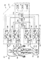
ここで、図11は、測定性能診断の対象となる、各カフ24ar,24al,24br,24blに対応した流体系30ar,30al,30br,30blを斜線を付して示している。カフ24arに対応した流体系30arは、圧力ポンプ25ar、調整弁26ar、圧力センサ28ar、内部配管27ar,27ar′、連絡配管22ar、および、流体袋21arを含む。カフ24alに対応した流体系30alは、圧力ポンプ25al、調整弁26al、圧力センサ28al、内部配管27al,27al′、連絡配管22al、および、流体袋21alを含む。カフ24brに対応した流体系30brは、圧力ポンプ25br、調整弁26br、圧力センサ28br、内部配管27br,27br′、連絡配管22br、および、流体袋21brを含む。カフ24blに対応した流体系30blは、圧力ポンプ25bl、調整弁26bl、圧力センサ28bl、内部配管27bl,27bl′、連絡配管22bl、および、流体袋21blを含む。この例では、各流体系30ar,30al,30br,30blの容量は、それぞれ対応するカフ内の流体袋21ar,21al,21br,21blの規制された容量を含んで、約300ccになっている(なお、連絡配管22ar,22al,22br,22blの長さの相違による容量差を無視するものとする。)。 Here, in FIG. 11, the fluid systems 30ar, 30al, 30br, 30bl corresponding to the respective cuffs 24ar, 24al, 24br, 24bl, which are the targets of the measurement performance diagnosis, are shown by hatching. The fluid system 30ar corresponding to the cuff 24ar includes a pressure pump 25ar, a regulating valve 26ar, a pressure sensor 28ar, internal piping 27ar, 27ar ', communication piping 22ar, and a fluid bag 21ar. The fluid system 30al corresponding to the cuff 24al includes a pressure pump 25al, a regulating valve 26al, a pressure sensor 28al, internal piping 27al, 27al ', communication piping 22al, and a fluid bag 21al. The fluid system 30br corresponding to the cuff 24br includes a pressure pump 25br, an adjustment valve 26br, a pressure sensor 28br, internal piping 27br, 27br ', a communication piping 22br, and a fluid bag 21br. The fluid system 30bl corresponding to the cuff 24bl includes a pressure pump 25bl, a regulating valve 26bl, a pressure sensor 28bl, internal piping 27bl, 27bl ', a communication piping 22bl, and a fluid bag 21bl. In this example, the capacity of each fluid system 30ar, 30al, 30br, 30bl is about 300 cc, including the regulated capacity of the corresponding fluid bag 21ar, 21al, 21br, 21bl in the cuff. The difference in capacity due to the difference in the length of the connecting pipes 22ar, 22al, 22br, 22bl is neglected.)
この例では、制御部2は、これらの流体系30ar,30al,30br,30blについて、同じフローで並行して測定性能診断処理を実行する。これにより、複数のカフ24ar,24al,24br,24blのうち、いずれのカフに対応した流体系30ar,30al,30br,30blに故障が生じているか否かを判定する。
In this example, the
以下の説明では、流体系30ar,30al,30br,30blは、特に区別する必要がない限り、これらを総称して、「流体系30」と呼ぶ。 In the following description, the fluid systems 30ar, 30al, 30br, and 30bl are collectively referred to as a "fluid system 30" unless otherwise required.
図9は、制御部2による、各流体系30についての測定性能診断処理(図8のステップS14)のフローを詳細に示している。
FIG. 9 shows the flow of the measurement performance diagnosis process (step S14 in FIG. 8) for each fluid system 30 by the
まず、図9のステップS21で、制御部2は、昇圧速度の良否を判定する。具体的には、図12に示すように、調整弁26を大気に対して閉じた状態で圧力ポンプ25を一定の駆動電圧で動作させて、流体系30の圧力Pxを0mmHgから基準圧P1(この例ではP1=285mmHgとする。)まで昇圧する。そして、流体系30の圧力Pxが基準圧P1に達するのに要した時間txを測定して、このときの昇圧速度PRx(=P1/tx)を算出する。この算出された昇圧速度PRxが下限値α1以上であれば、「良」と判定する。一方、算出された昇圧速度PRxが下限値α1未満であれば、「否」と判定する。この例では、流体系30の規制された容量(約300cc)に応じて、予め、昇圧速度PRxのための下限値はα1=4.8mmHg/sに設定されている。これにより、昇圧速度の良否を適切に判定できる。
First, in step S21 of FIG. 9, the
続いて、図9のステップS22で、制御部2は、漏気量の良否を判定する。具体的には、図13に示すように、昇圧速度の良否判定のために基準圧P1に達した後、流体系30を時刻t1から時刻t2までの一定期間Δt(=t2−t1)だけ閉じた状態に保つ。この例では、Δtは60s(秒)に設定されている。そして、時刻t1での流体系30の圧力Px1と、時刻t2での流体系30の圧力Px2とを測定して、圧力差ΔPx(=Px1−Px2)を算出する。この算出された圧力差ΔPxが上限値α2以下であれば、「良」と判定する。一方、算出された圧力差ΔPxが上限値α2を超えていれば、「否」と判定する。この例では、流体系30の規制された容量(約300cc)に応じて、予め、漏気量のための上限値はα2=6.0mmHg/60sに設定されている。これにより、漏気量の良否を適切に判定できる。
Subsequently, in step S22 of FIG. 9, the
次に、図9のステップS23で、制御部2は、排気速度の良否を判定する。具体的には、調整弁26を開いて流体系30内の空気を一旦排気した後、調整弁26を大気に対して閉じた状態で圧力ポンプ25を一定の駆動電圧で動作させて、流体系30の圧力Pxを基準圧P3(この例ではP3=285mmHgとする。)を超える圧力まで昇圧する。この後、図14に示すように、時刻tx3で調整弁26を大気に対して一定の開度で開いて、流体系30の圧力Pxを基準圧P3から下方の基準圧P4(この例ではP4=40mmHgとする。)まで低下させる。そして、流体系30の圧力Pxが基準圧P4に達した時刻tx4を測定して、排気速度PSx(=(P3−P4)/(tx4−tx3))を算出する。この算出された排気速度PSxが下限値α3以上かつ上限値α4以下であれば、「良」と判定する。一方、算出された排気速度PSxが下限値α3未満または上限値α4超であれば、「否」と判定する。この例では、流体系30の規制された容量(約300cc)に応じて、予め、排気速度PSxのための下限値はα3=3.5mmHg/s、上限値はα4=6.0mmHg/sに設定されている。これにより、排気速度の良否を適切に判定できる。
Next, in step S23 in FIG. 9, the
次に、図9のステップS24で、制御部2は、累積された通算の測定回数が上限回数を超えたか否かを判定する。具体的には、制御部2が、図3中の記憶装置8に記憶されている累積された通算の測定回数Nを読み出して、予め定められた上限回数ULと比較する。そして、累積された通算の測定回数Nが上限回数UL以下であれば、「良」と判定する。一方、累積された通算の測定回数Nが上限回数ULを超えていれば、「否」と判定する。この例では、予め、上限回数ULは60000回に設定されている。
Next, in step S24 of FIG. 9, the
図9のステップS21〜S24までの処理に要する時間は、この例ではトータルで約4分間である。 The time required for the processing of steps S21 to S24 in FIG. 9 is about 4 minutes in total in this example.
各測定項目について、測定された数値(測定値)と判定結果との対応関係は、次の表1のように表される。なお、漏気量、昇圧速度、排気速度の測定値の有効数字は、この例では2桁になっている。
(表1)

(Table 1)
制御部2は、このようにして図9のステップS21〜S24までの測定性能診断処理を、複数の流体系30ar,30al,30br,30blについてそれぞれ並行して実行する。これにより、複数のカフ24のうち、いずれのカフ24に対応した流体系30に故障が生じているか否か、また、複数の測定項目のうち、いずれの測定項目について故障が生じているか否かを判定できる。したがって、ユーザが特別の治具を用いることなく簡単な操作(主に、カフ24を空巻きする操作)を行うのみで、流体系30の様々な故障の有無を判定できる。
The
各流体系30についての測定性能診断が完了すると、図8のステップS15に示すように、制御部2が出力部4を第1出力部および第2出力部として動作させて、測定性能診断の結果を出力する。
When the measurement performance diagnosis for each fluid system 30 is completed, the
図16は、出力部4によってメインユニット101の表示画面40に表示された測定性能診断の結果を例示している。この例では、最上段に「メンテナンスメニュー >測定性能診断」という標題が表示されている。その下方に診断結果が表形式で表示されている。この診断結果の表では、表頭の「右上腕」、「左上腕」、「右足首」、「左足首」という表示は、それぞれ診断対象の流体系30br,30bl,30ar,30alに対応している。表側の「漏気量」、「昇圧速度」、「排気速度」、「測定回数」という表示は、4つの測定項目に対応している。表体の「○」、「×」は、それぞれ対応する流体系30毎の、対応する測定項目についての判定結果の良否(すなわち、故障の有無)を表している。
FIG. 16 illustrates a result of the measurement performance diagnosis displayed on the
この図16の例によれば、ユーザは、「右上腕」に対応する流体系30brについて、漏気量の判定結果が「否」、昇圧速度の判定結果が「良」、排気速度の判定結果が「良」、測定回数の判定結果が「良」であることを、知ることができる。また、「左上腕」に対応する流体系30blについては、漏気量、昇圧速度、排気速度、測定回数の判定結果がいずれも「良」であることを、知ることができる。同様に、「右足首」に対応する流体系30ar、「左足首」に対応する流体系30alについても、漏気量、昇圧速度、排気速度、測定回数の判定結果がいずれも「良」であることを、知ることができる。このように、ユーザは、各カフ24に対応した流体系30毎に、また、各測定項目毎に、故障の有無の判定結果を知ることができる。 According to the example of FIG. 16, for the fluid system 30br corresponding to the “upper right arm”, the user determines that the leakage amount determination result is “No”, the boosting speed determination result is “Good”, and the exhaust speed determination result. Is "good", and the determination result of the number of measurements is "good". In addition, for the fluid system 30bl corresponding to the “left upper arm”, it can be known that the determination results of the air leakage amount, the pressure increase speed, the exhaust speed, and the number of measurements are all “good”. Similarly, for the fluid system 30ar corresponding to the “right ankle” and the fluid system 30al corresponding to the “left ankle”, the determination results of the air leak amount, the pressure increase speed, the exhaust speed, and the number of measurements are all “good”. You can know that. In this way, the user can know the determination result of the presence or absence of a failure for each fluid system 30 corresponding to each cuff 24 and for each measurement item.
図17は、出力部4としての図示しないプリンタによってプリントアウトされた測定性能診断の結果を例示している。このプリントアウトでは、枠71外(上部)で左端に、「測定性能診断」という標題が表示され、また、右端に出力の年月日と時刻(この例では「2016/02/23 17:25」)が表示されている。枠71内の上部には、「診断結果」が表形式で表示されている。その下方には、「総合結果」が文章で表示されている。
FIG. 17 illustrates a result of the measurement performance diagnosis printed out by a printer (not shown) as the
この図17の「診断結果」の表の見方は、図16の表示画面40における診断結果の見方と同じに設定されている。これにより、ユーザは、各カフ24に対応した流体系30毎に、また、各測定項目毎に、故障の有無の判定結果を知ることができる。さらに、この「診断結果」の表では、表体の「○」、「×」の直下に、測定された漏気量、昇圧速度、排気速度、測定回数を表す数値が、それぞれ併せて示されている。したがって、ユーザは、それぞれの判定の根拠も知ることができる。
The way of viewing the table of “diagnosis result” in FIG. 17 is set to be the same as the way of viewing the diagnosis result on the
この図17の「診断結果」の例では、「右上腕」に対応する流体系30brについて、排気速度の判定結果が「否」になっている。流体系30brのそれ以外の測定項目、および、それ以外の流体系30bl,30ar,30alについては、問題が無い。これに応じて、図17中の「総合結果」欄には、「<右上腕> 測定性能の低下がみられます。カフを巻き直して測定ボタンを押し、診断を再実施してください。同じ結果が繰り返し表示される場合は、保守サービスを受けてください。」というメッセージが表示されている。それ以外の「左上腕」、「右足首」、「左足首」に対応する流体系30bl,30ar,30alについては、それぞれ「測定性能に問題はありません。」というメッセージが表示されている。これらのメッセージを見たユーザは、この装置の測定性能の現状に対して、どのように対処すべきかを具体的に知ることができる。例えば、これらのメッセージを見たユーザが医療従事者である場合は、保守サービスマンを呼ぶなどの対処を迅速にとることができる。 In the example of the “diagnosis result” of FIG. 17, the determination result of the exhaust speed is “no” for the fluid system 30br corresponding to the “upper right arm”. There is no problem about the other measurement items of the fluid system 30br and the other fluid systems 30bl, 30ar, and 30al. In response to this, in the “Overall result ” column in FIG. 17, “<Upper right arm> The measurement performance is degraded. Rewind the cuff, press the measurement button, and perform the diagnosis again. If the result is displayed repeatedly, call for service. "Is displayed. For the other fluid systems 30bl, 30ar, and 30al corresponding to "left upper arm", "right ankle", and "left ankle", a message "There is no problem in measurement performance" is displayed. The user who sees these messages can know specifically how to deal with the current state of the measurement performance of the device. For example, if the user who sees these messages is a medical worker, it is possible to quickly take measures such as calling a maintenance serviceman.
上述の実施形態では、カフ24ar,24al,24br,24blが、専ら、右足首、左足首、右上腕、左上腕に装着される例について説明した。しかしながら、これに限られるものではない。カフ24ar,24al,24br,24blが装着される被測定部位は、手首や指尖部などであってもよい。 In the above-described embodiment, an example has been described in which the cuffs 24ar, 24al, 24br, and 24bl are exclusively worn on the right ankle, the left ankle, the right upper arm, and the left upper arm. However, it is not limited to this. The measurement site to which the cuffs 24ar, 24al, 24br, 24bl are attached may be a wrist, a fingertip, or the like.
また、測定性能診断の対象となるカフ24およびカフ24に対応した流体系30の数は、4つに限られるものではなく、例えば1つのみ、2つのみ、またはそれ以外の数であっても良い。 Further, the number of cuffs 24 to be subjected to the measurement performance diagnosis and the number of fluid systems 30 corresponding to the cuffs 24 are not limited to four, and may be, for example, only one, only two, or other numbers. Is also good.
また、この発明は、カフと血圧測定のための要素を搭載した本体とが短円筒状の連絡配管を介して一体に構成された、いわゆる一体型血圧計にも適用され得る。 The present invention can also be applied to a so-called integrated blood pressure monitor in which a cuff and a main body on which an element for measuring blood pressure are mounted are integrally formed via a short cylindrical communication pipe.
以上の実施形態は例示であり、この発明の範囲から離れることなく様々な変形が可能である。上述した複数の実施の形態は、それぞれ単独で成立し得るものであるが、実施の形態同士の組みあわせも可能である。また、異なる実施の形態の中の種々の特徴も、それぞれ単独で成立し得るものであるが、異なる実施の形態の中の特徴同士の組みあわせも可能である。 The above embodiment is an exemplification, and various modifications can be made without departing from the scope of the present invention. Each of the above-described embodiments can be realized independently, but combinations of the embodiments are also possible. In addition, various features in different embodiments can also be independently realized, but combinations of features in different embodiments are also possible.
2 制御部
21,21ar,21al,21br,21bl 流体袋
22,22ar,22al,22br,22bl 連絡配管
24,24ar,24al,24br,24bl カフ
25,25ar,25al,25br,25bl 圧力ポンプ
26,26ar,26al,26br,26bl 調整弁
27,27ar,27al,27br,27bl,27′,27ar′,27al′,27br′,27bl′ 内部配管
30,30br,30bl,30ar,30al 流体系
40 表示画面
100 血圧脈波測定装置
401 内布
402 カーラ
403 外布
409 目盛
2 Control unit 21, 21 ar, 21 al, 21 br, 21 bl Fluid bag 22, 22, ar, 22 al, 22 br, 22 bl Communication pipe 24, 24 ar, 24 al, 24 br, 24 bl Cuff 25, 25 ar, 25 al, 25 br, 25 bl Pressure pump 26, 26 ar, 26al, 26br, 26bl Regulator valve 27, 27ar, 27al, 27br, 27bl, 27 ', 27ar', 27al ', 27br', 27bl 'Internal piping 30, 30br, 30bl, 30ar,
Claims (8)
血圧測定のための要素として、ポンプ、弁、圧力センサ、および、これらのポンプ、弁、圧力センサを互いに流体流通可能に接続する内部配管を含むユニットと、
上記カフと上記ユニット内の上記内部配管とを互いに流体流通可能に接続する連絡配管と、
を備えて、血圧測定を行う血圧計において、
上記カフに、このカフの中心を空にして、このカフのみを筒状に巻く空巻きが行われるとき、このカフの筒の周りの寸法を定める目安となるマークが設けられ、
上記カフが上記マークに合わせて筒状に空巻きされて上記カフの容量が規制された状態で、上記ポンプ、上記弁、上記圧力センサ、上記内部配管、上記連絡配管、および、上記カフを含む流体系の故障の有無を判定する自己故障診断部を備えたことを特徴とする血圧計。 A cuff to be wrapped around the part to be measured,
As a component for measuring blood pressure, a unit including a pump, a valve, a pressure sensor, and an internal pipe that connects the pump, the valve, and the pressure sensor to each other so that fluid can flow therebetween;
A communication pipe that connects the cuff and the internal pipe in the unit so that fluid can flow therebetween;
In the sphygmomanometer that performs blood pressure measurement,
In the cuff, when the center of the cuff is emptied, and when the empty cuff is wound around the cuff only in the form of a cylinder, a mark is provided as a guide for determining the dimension around the cylinder of the cuff,
The pump, the valve, the pressure sensor, the internal pipe, the communication pipe, and the cuff are included in a state in which the cuff is hollowly wound in a cylindrical shape in accordance with the mark and the capacity of the cuff is regulated. A sphygmomanometer, comprising: a self-diagnosis unit for determining whether a fluid system has failed.
上記カフの上記規制された容量を含む上記流体系の規制された容量に応じて、少なくとも、昇圧速度、漏気量、排気速度を含む複数の測定項目について、それぞれ上限値または下限値が予め設定されており、
上記自己故障診断部は、少なくとも、上記昇圧速度、漏気量、排気速度を含む複数の測定項目について、それぞれ上記流体系の上記規制された容量に応じて上記予め設定されている上限値または下限値との比較を行って、良否を判定することを特徴とする血圧計。 The sphygmomanometer according to claim 1,
According to the regulated volume of the fluid system including the regulated volume of the cuff, at least an upper limit value or a lower limit value is preset for each of a plurality of measurement items including a boosting rate, a leak rate, and an exhaust rate. Has been
The self-fault diagnostic unit, at least, the rate of rise, the air leakage amount for a plurality of measurement items including pumping speed, the upper limit or lower limit is the preset in accordance with the regulated volume of each said fluid system A sphygmomanometer characterized in that a pass / fail is determined by comparing the value with a value.
上記カフは、上記被測定部位に接すべき内布とこの内布に対向する外布との間に上記連絡配管と連通する流体袋を内包し、さらに、上記外布と上記流体袋との間に、自然状態で上記カフの形状を上記被測定部位を取り巻くべき筒状に維持するとともに、上記空巻きされた状態で芯となるカーラを有することを特徴とする血圧計。 The blood pressure monitor according to claim 1 or 2,
The cuff includes a fluid bag that communicates with the communication pipe between an inner cloth that is to be in contact with the measurement target portion and an outer cloth that faces the inner cloth. A sphygmomanometer, characterized in that the cuff has a cylindrical shape surrounding the measurement site in a natural state and has a curler serving as a core in the wound state .
上記カフに、上記マークとして、このカフの長手方向に関して目盛が設けられていることを特徴とする血圧計。 The blood pressure monitor according to any one of claims 1 to 3,
A blood pressure monitor, wherein a scale is provided on the cuff as the mark in a longitudinal direction of the cuff.
操作入力に応じて、上記血圧測定を行うモードとは別に、上記自己故障診断部を動作させるための測定性能診断モードを設定する制御部を備えたことを特徴とする血圧計。 The blood pressure monitor according to any one of claims 1 to 4,
A sphygmomanometer, comprising: a control unit that sets a measurement performance diagnosis mode for operating the self-failure diagnosis unit, in addition to a mode for performing the blood pressure measurement in accordance with an operation input.
上記複数の測定項目について、それぞれ良否の判定結果を出力する第1出力部を備えたことを特徴とする血圧計。 The sphygmomanometer according to claim 2,
A sphygmomanometer, comprising: a first output unit that outputs a determination result of good or bad for each of the plurality of measurement items.
上記カフは複数設けられ、
上記ユニットは、各カフに対応して上記血圧測定のための要素を含み、
上記各カフと上記ユニット内の対応する上記内部配管とが互いに上記連絡配管によって接続され、
上記自己故障診断部は、上記各カフに対応した流体系毎に故障の有無を判定することを特徴とする血圧計。 The blood pressure monitor according to any one of claims 1 to 6,
A plurality of the cuffs are provided,
The unit includes an element for measuring the blood pressure corresponding to each cuff,
The cuffs and the corresponding internal pipes in the unit are connected to each other by the communication pipes,
The sphygmomanometer according to claim 1, wherein the self-diagnosis unit determines presence or absence of a failure for each fluid system corresponding to each of the cuffs.
上記各カフに対応した流体系毎に故障の有無の判定結果を出力する第2出力部を備えたことを特徴とする血圧計。 The sphygmomanometer according to claim 7,
A sphygmomanometer, comprising: a second output unit that outputs a determination result of the presence or absence of a failure for each fluid system corresponding to each of the cuffs.
Priority Applications (5)
| Application Number | Priority Date | Filing Date | Title |
|---|---|---|---|
| JP2016124766A JP6658332B2 (en) | 2016-06-23 | 2016-06-23 | Sphygmomanometer |
| DE112017003114.1T DE112017003114T5 (en) | 2016-06-23 | 2017-05-25 | Blood Pressure Monitor |
| CN201780037660.9A CN109310350B (en) | 2016-06-23 | 2017-05-25 | Sphygmomanometer |
| PCT/JP2017/019565 WO2017221627A1 (en) | 2016-06-23 | 2017-05-25 | Sphygmomanometer |
| US16/212,532 US11547308B2 (en) | 2016-06-23 | 2018-12-06 | Blood pressure monitor |
Applications Claiming Priority (1)
| Application Number | Priority Date | Filing Date | Title |
|---|---|---|---|
| JP2016124766A JP6658332B2 (en) | 2016-06-23 | 2016-06-23 | Sphygmomanometer |
Publications (3)
| Publication Number | Publication Date |
|---|---|
| JP2017225697A JP2017225697A (en) | 2017-12-28 |
| JP2017225697A5 JP2017225697A5 (en) | 2019-05-23 |
| JP6658332B2 true JP6658332B2 (en) | 2020-03-04 |
Family
ID=60784445
Family Applications (1)
| Application Number | Title | Priority Date | Filing Date |
|---|---|---|---|
| JP2016124766A Active JP6658332B2 (en) | 2016-06-23 | 2016-06-23 | Sphygmomanometer |
Country Status (5)
| Country | Link |
|---|---|
| US (1) | US11547308B2 (en) |
| JP (1) | JP6658332B2 (en) |
| CN (1) | CN109310350B (en) |
| DE (1) | DE112017003114T5 (en) |
| WO (1) | WO2017221627A1 (en) |
Families Citing this family (4)
| Publication number | Priority date | Publication date | Assignee | Title |
|---|---|---|---|---|
| JP7147666B2 (en) * | 2019-04-03 | 2022-10-05 | オムロンヘルスケア株式会社 | Sphygmomanometer |
| CN110200611A (en) * | 2019-06-19 | 2019-09-06 | 健仕医疗技术(浙江)有限公司 | A kind of oscillographic method electronic sphygmomanometer and its measurement method |
| JP7272900B2 (en) * | 2019-08-08 | 2023-05-12 | フクダ電子株式会社 | Biological information measuring device, inspection method and inspection program for biological information measuring device |
| CN110974200A (en) * | 2019-12-09 | 2020-04-10 | 深圳科讯恒达医疗科技有限公司 | Sphygmomanometer calibration method and system, electronic sphygmomanometer and calibration server |
Family Cites Families (34)
| Publication number | Priority date | Publication date | Assignee | Title |
|---|---|---|---|---|
| US4718426A (en) * | 1984-02-17 | 1988-01-12 | Cortronic Corporation | Method for determining diastolic arterial blood pressure in a subject |
| US4718428A (en) * | 1984-02-17 | 1988-01-12 | Cortronic Corporation | Method for determining diastolic arterial blood pressure in a subject |
| US4718427A (en) * | 1984-02-17 | 1988-01-12 | Cortronic Corporation | Method for determining systolic arterial blood pressure in a subject |
| US4669485A (en) * | 1984-02-17 | 1987-06-02 | Cortronic Corporation | Apparatus and method for continuous non-invasive cardiovascular monitoring |
| EP0342249B1 (en) * | 1988-05-14 | 1991-01-09 | Hewlett-Packard GmbH | Blood pressure monitor |
| JPH07178065A (en) | 1993-12-22 | 1995-07-18 | Matsushita Electric Works Ltd | Testing method of sphygmomanometer and sphygmomanometer |
| JP3820699B2 (en) * | 1997-08-29 | 2006-09-13 | セイコーエプソン株式会社 | Pulse wave detector |
| US6602469B1 (en) * | 1998-11-09 | 2003-08-05 | Lifestream Technologies, Inc. | Health monitoring and diagnostic device and network-based health assessment and medical records maintenance system |
| US6152881A (en) * | 1999-03-29 | 2000-11-28 | Vasocor, Inc. | Calibrated measurement of blood vessels and endothelium after reactive hyperemia and method therefor |
| JP2002078686A (en) * | 2000-09-11 | 2002-03-19 | Citizen Watch Co Ltd | Sphygmomanometer |
| JP4687323B2 (en) * | 2005-08-12 | 2011-05-25 | オムロンヘルスケア株式会社 | Blood pressure measurement device |
| JP4770727B2 (en) * | 2006-12-14 | 2011-09-14 | パナソニック電工株式会社 | Blood pressure measurement device |
| JP5303939B2 (en) * | 2008-01-23 | 2013-10-02 | オムロンヘルスケア株式会社 | Blood pressure monitor measurement accuracy confirmation system |
| JP5095463B2 (en) * | 2008-03-26 | 2012-12-12 | フクダ電子株式会社 | Biological information measuring device |
| JP2010057817A (en) * | 2008-09-05 | 2010-03-18 | Omron Healthcare Co Ltd | Electronic sphygmomanometer |
| JP5239806B2 (en) * | 2008-12-09 | 2013-07-17 | オムロンヘルスケア株式会社 | Electronic blood pressure monitor |
| JP5152153B2 (en) * | 2009-10-30 | 2013-02-27 | オムロンヘルスケア株式会社 | Electronic blood pressure monitor |
| JP5195723B2 (en) * | 2009-11-13 | 2013-05-15 | オムロンヘルスケア株式会社 | Electronic blood pressure monitor |
| US20110213218A1 (en) * | 2009-12-17 | 2011-09-01 | Weiner Bert A | Patient healthcare monitoring/maintenance system |
| US9289545B2 (en) * | 2009-12-28 | 2016-03-22 | Gambro Lundia Ab | Controlling an apparatus for fluid transfer to and/or from a subject |
| JP2011200290A (en) | 2010-03-24 | 2011-10-13 | Omron Healthcare Co Ltd | Electronic sphygmomanometer and determination method |
| JP5640527B2 (en) * | 2010-07-28 | 2014-12-17 | オムロンヘルスケア株式会社 | Blood pressure measuring device |
| CN106073731B (en) * | 2011-02-17 | 2020-01-31 | 高通股份有限公司 | Method and system for determining cardiovascular quantity of mammal |
| JP2012210362A (en) * | 2011-03-31 | 2012-11-01 | Terumo Corp | Limb compression device |
| WO2012138982A2 (en) * | 2011-04-06 | 2012-10-11 | Coolsystems, Inc. | Control unit for a therapy system and method |
| TW201306798A (en) * | 2011-08-08 | 2013-02-16 | Ostar Meditech Corp | Blood pressure measurement system with automatic inspection and self-calibration functions |
| CN102920448A (en) * | 2011-08-12 | 2013-02-13 | 张国源 | Blood pressure measuring device and system capable of automatically testing and calibrating self accuracy |
| JP5853587B2 (en) * | 2011-10-26 | 2016-02-09 | オムロンヘルスケア株式会社 | Electronic blood pressure monitor |
| JP3174904U (en) * | 2012-02-01 | 2012-04-12 | オムロンヘルスケア株式会社 | Wrist sphygmomanometer |
| CN103426351B (en) * | 2013-07-11 | 2018-05-18 | 牛欣 | Can the arteries and veins aroused in interest of remote reproduction answer diagnosis by feeling the pulse training device and method |
| CN203539343U (en) * | 2013-10-30 | 2014-04-16 | 苏州百慧华业精密仪器有限公司 | Security monitoring circuit for oscillography sphygmomanometer |
| CN104688212A (en) * | 2013-12-09 | 2015-06-10 | 苏州九域星医疗科技有限公司 | Blood pressure and heart rate test instrument |
| CN104274166B (en) * | 2014-08-19 | 2017-09-29 | 深圳市理邦精密仪器股份有限公司 | A kind of pressure sensor failure detection method and device |
| CN105078431B (en) * | 2015-10-10 | 2018-02-23 | 杨胜周 | Wearable blood pressure meter cuff, its sphygmomanometer and application method |
-
2016
- 2016-06-23 JP JP2016124766A patent/JP6658332B2/en active Active
-
2017
- 2017-05-25 CN CN201780037660.9A patent/CN109310350B/en active Active
- 2017-05-25 DE DE112017003114.1T patent/DE112017003114T5/en active Pending
- 2017-05-25 WO PCT/JP2017/019565 patent/WO2017221627A1/en active Application Filing
-
2018
- 2018-12-06 US US16/212,532 patent/US11547308B2/en active Active
Also Published As
| Publication number | Publication date |
|---|---|
| US20190104950A1 (en) | 2019-04-11 |
| US11547308B2 (en) | 2023-01-10 |
| JP2017225697A (en) | 2017-12-28 |
| WO2017221627A1 (en) | 2017-12-28 |
| CN109310350A (en) | 2019-02-05 |
| DE112017003114T5 (en) | 2019-03-07 |
| CN109310350B (en) | 2021-06-04 |
Similar Documents
| Publication | Publication Date | Title |
|---|---|---|
| JP6658332B2 (en) | Sphygmomanometer | |
| JP5589501B2 (en) | Blood pressure measuring device | |
| JP5565164B2 (en) | Electronic blood pressure monitor | |
| JP2009284967A (en) | Cuff for blood pressure data measuring instrument and blood pressure data measuring instrument equipped with it | |
| JP7380162B2 (en) | Sphygmomanometer | |
| US20220000380A1 (en) | Sphygmomanometer | |
| JP2017225697A5 (en) | ||
| JP5141666B2 (en) | Electronic blood pressure monitor | |
| JP2011103984A (en) | Electronic sphygmomanometer | |
| JP5195722B2 (en) | Electronic blood pressure monitor | |
| CN108778103B (en) | Blood pressure pulse wave measuring device | |
| KR20100094059A (en) | Apparatus and method for automatic measurement and wireless transmission of blood pressure values based on oscillometric method and k-sound method | |
| JP7281777B2 (en) | Blood pressure measurement system and blood pressure measurement method using the same | |
| JP2012061215A (en) | Blood pressure information measuring device | |
| JP6676915B2 (en) | Blood pressure measurement device, blood pressure measurement system, and blood pressure measurement method | |
| JP7367478B2 (en) | Blood pressure monitor, blood pressure measurement method, and program | |
| US20230125180A1 (en) | Blood pressure measurement system utilizing auscultatory signal acquisition | |
| KR20180042612A (en) | Blood Pressure Measuring Apparatus | |
| JP7354792B2 (en) | Blood pressure monitor, blood pressure measurement method, and program | |
| JP5366704B2 (en) | Biological information measuring device | |
| US20230143560A1 (en) | Sphygmomanometer, blood pressure measurement method, and computer-readable recording medium | |
| JP2012115413A (en) | Electronic sphygmomanometer | |
| CN109195512B (en) | Blood pressure pulse wave measuring device | |
| JP2021078552A5 (en) |
Legal Events
| Date | Code | Title | Description |
|---|---|---|---|
| A521 | Request for written amendment filed |
Free format text: JAPANESE INTERMEDIATE CODE: A523 Effective date: 20190411 |
|
| A621 | Written request for application examination |
Free format text: JAPANESE INTERMEDIATE CODE: A621 Effective date: 20190411 |
|
| TRDD | Decision of grant or rejection written | ||
| A01 | Written decision to grant a patent or to grant a registration (utility model) |
Free format text: JAPANESE INTERMEDIATE CODE: A01 Effective date: 20200107 |
|
| A61 | First payment of annual fees (during grant procedure) |
Free format text: JAPANESE INTERMEDIATE CODE: A61 Effective date: 20200120 |
|
| R150 | Certificate of patent or registration of utility model |
Ref document number: 6658332 Country of ref document: JP Free format text: JAPANESE INTERMEDIATE CODE: R150 |