JP6571616B2 - Robot simulation device - Google Patents
Robot simulation device Download PDFInfo
- Publication number
- JP6571616B2 JP6571616B2 JP2016173015A JP2016173015A JP6571616B2 JP 6571616 B2 JP6571616 B2 JP 6571616B2 JP 2016173015 A JP2016173015 A JP 2016173015A JP 2016173015 A JP2016173015 A JP 2016173015A JP 6571616 B2 JP6571616 B2 JP 6571616B2
- Authority
- JP
- Japan
- Prior art keywords
- robot
- hand
- tool
- setting unit
- simulation
- Prior art date
- Legal status (The legal status is an assumption and is not a legal conclusion. Google has not performed a legal analysis and makes no representation as to the accuracy of the status listed.)
- Active
Links
Images


Classifications
-
- B—PERFORMING OPERATIONS; TRANSPORTING
- B25—HAND TOOLS; PORTABLE POWER-DRIVEN TOOLS; MANIPULATORS
- B25J—MANIPULATORS; CHAMBERS PROVIDED WITH MANIPULATION DEVICES
- B25J9/00—Programme-controlled manipulators
- B25J9/16—Programme controls
- B25J9/1656—Programme controls characterised by programming, planning systems for manipulators
- B25J9/1671—Programme controls characterised by programming, planning systems for manipulators characterised by simulation, either to verify existing program or to create and verify new program, CAD/CAM oriented, graphic oriented programming systems
-
- B—PERFORMING OPERATIONS; TRANSPORTING
- B25—HAND TOOLS; PORTABLE POWER-DRIVEN TOOLS; MANIPULATORS
- B25J—MANIPULATORS; CHAMBERS PROVIDED WITH MANIPULATION DEVICES
- B25J9/00—Programme-controlled manipulators
- B25J9/16—Programme controls
- B25J9/1602—Programme controls characterised by the control system, structure, architecture
- B25J9/1605—Simulation of manipulator lay-out, design, modelling of manipulator
Description
本発明は、ロボットシミュレーション装置に関するものである。 The present invention relates to a robot simulation apparatus.
従来、ロボットの動作を画面上でシミュレーションするロボットシミュレーション装置が知られている(例えば、特許文献1参照。)。このロボットシミュレーション装置は、ハンドを取り付けたロボットのシミュレーションを実施しながら、ケース内に山積みされたワークをハンドによってケースから取り出す際に、ハンドとケースに干渉が生じないようにハンドの形状モデルを変更して、変更後のハンドの形状モデルから実際のハンドの寸法データを取得するようになっている。 Conventionally, a robot simulation apparatus that simulates the operation of a robot on a screen is known (see, for example, Patent Document 1). This robot simulation device changes the shape model of the hand so that it does not interfere with the case when removing the work stacked in the case from the case while performing the simulation of the robot with the hand attached Thus, the actual hand dimension data is obtained from the changed hand shape model.
しかしながら、ハンドの設計には設計者のノウハウが必要であり、干渉を回避できるように変形された形状が必ずしもハンドの必要な機能を満足しているとは限らないという不都合がある。
本発明は上述した事情に鑑みてなされたものであって、必要な機能を満足しかつ周辺機器との干渉を回避することができるツールの設計を簡易に行うことができるロボットシミュレーション装置を提供することを目的としている。
However, the design of the hand requires the know-how of the designer, and there is an inconvenience that the shape deformed so as to avoid interference does not necessarily satisfy the necessary function of the hand.
The present invention has been made in view of the above-described circumstances, and provides a robot simulation apparatus that can easily design a tool that satisfies necessary functions and can avoid interference with peripheral devices. The purpose is that.
上記目的を達成するため、本発明は以下の手段を提供する。
本発明の一態様は、ツールに備えられる1以上のハンドの種類を設定するツール情報設定部と、前記ハンドの種類と該ハンドの3次元モデルおよびツール座標系とを対応づけて記憶するハンドモデル記憶部と、ユーザによる入力に基づき、前記ツールの前記1以上の前記ハンドの各々のロボットの取付面に対する位置および姿勢を設定するハンド位置姿勢設定部と、前記ツール情報設定部により設定された前記ハンドの種類に基づいて前記ハンドモデル記憶部から読み出した前記ハンドの3次元モデルを前記ハンド位置姿勢設定部により設定された前記ハンドの位置および姿勢で前記取付面に取り付けた前記ロボットの3次元モデルを生成し、ツール座標系を設定するロボットモデル生成部とを備え、該ロボットモデル生成部により生成された前記ロボットの3次元モデルおよび前記ツール座標系を用いて、前記ツールが前記取付面に取り付けられた前記ロボットのシミュレーションを行い、該シミュレーションの後に、前記1以上のハンドの各々の前記取付面に対する位置および姿勢がユーザによる入力に基づいて前記ハンド位置姿勢設定部によって変更されるロボットシミュレーション装置を提供する。
In order to achieve the above object, the present invention provides the following means.
One aspect of the present invention provides a tool information setting unit that sets one or more types of hands provided in a tool, and a hand model that stores the type of hand, a three-dimensional model of the hand, and a tool coordinate system in association with each other. Based on an input by a user, a hand position / posture setting unit that sets a position and a posture of each of the one or more hands of the tool with respect to a mounting surface of the robot, and the tool information setting unit A three-dimensional model of the robot in which the three-dimensional model of the hand read from the hand model storage unit based on the type of the hand is attached to the attachment surface with the position and posture of the hand set by the hand position and orientation setting unit And a robot model generation unit that sets a tool coordinate system, and is generated by the robot model generation unit. By using a three-dimensional model and the tool coordinate system of the robot, a simulation of the robot the tool is attached to the mounting surface, after the simulation, the position relative to the mounting surface of each of the one or more hand And a robot simulation device whose posture is changed by the hand position and posture setting unit based on an input by a user .
本態様によれば、ツール情報設定部により、ツールに備えられる1以上のハンドの種類が設定され、ハンド位置姿勢設定部によりロボットの取付面に取り付けられるツールにおける各ハンドの位置および姿勢が設定されると、ハンドモデル記憶部に記憶されているハンドの3次元モデルおよびツール座標系が読み出され、ロボットモデル生成部において、設定された位置および姿勢で取付面にツールが取り付けられ、ツール座標系が設定されたロボットの3次元モデルが生成される。これにより、取付面にツールが取り付けられたロボットのシミュレーションが、ハンドのツール座標系を用いて行われる。 According to this aspect, the tool information setting unit sets one or more types of hands included in the tool, and the hand position / posture setting unit sets the position and posture of each hand in the tool attached to the mounting surface of the robot. Then, the three-dimensional model of the hand and the tool coordinate system stored in the hand model storage unit are read out, and the tool is attached to the mounting surface at the set position and orientation in the robot model generation unit. A three-dimensional model of the robot for which is set is generated. Thereby, the simulation of the robot with the tool attached to the attachment surface is performed using the tool coordinate system of the hand.
すなわち、本態様によれば、必要情報を入力するだけで、予め記憶されているツールの3次元モデルおよびツール座標系が選択され、ロボットの取付面に所望の位置および角度でツールを取り付けたロボットのシミュレーションを簡易に行うことができる。したがって、入力する情報を変更して、種々のツールを装着したロボットについてシミュレーションを簡易に行って、ツール毎の干渉チェックやサイクルタイムの評価等を簡易に行うことができる。この場合に、予め記憶されているハンドの3次元モデルを用いるので、必要な機能を満たしたツールによるシミュレーションを行うことができる。 That is, according to this aspect, the robot in which the tool is attached to the attachment surface of the robot at a desired position and angle by selecting a pre-stored three-dimensional model and tool coordinate system simply by inputting necessary information. Can be easily performed. Therefore, it is possible to easily perform simulation for a robot equipped with various tools by changing information to be input, and to perform interference check for each tool, evaluation of cycle time, and the like. In this case, since a three-dimensional model of the hand stored in advance is used, it is possible to perform a simulation with a tool that satisfies a necessary function.
上記態様においては、前記ツールが、前記ハンドと該ハンドを前記ロボットに取り付けるための取付部材とを備え、前記ハンド位置姿勢設定部が、前記取付部材の形状を設定してもよい。
このようにすることで、ハンド位置姿勢設定部により取付部材の形状を設定することによって、ロボットの取付面に取り付けるハンドの位置および姿勢を簡易に設定することができる。
In the above aspect, the tool may include the hand and an attachment member for attaching the hand to the robot, and the hand position / posture setting unit may set the shape of the attachment member.
By doing in this way, the position and attitude | position of the hand attached to the attachment surface of a robot can be simply set by setting the shape of an attachment member by a hand position and orientation setting part.
また、上記態様においては、前記ハンドが、ハンド本体と、該ハンド本体に対して移動する1以上の爪とを備え、前記ツール情報設定部が、前記爪の種類および大きさを設定してもよい。
このようにすることで、ハンドの動作時に、ハンド本体の可動部により移動させられる
1以上の爪を所望の種類および大きさに設定してシミュレーションを行うことができる。
Moreover, in the said aspect, the said hand is provided with a hand main body and one or more nail | claw which moves with respect to this hand main body, The said tool information setting part sets the kind and magnitude | size of the said nail | claw. Good.
By doing in this way, at the time of operation | movement of a hand, one or more nail | claw moved by the movable part of a hand main body can be set to a desired kind and magnitude | size, and a simulation can be performed.
また、上記態様においては、前記ハンドが前記爪の動作を開始させる際に前記ロボットから出力される出力信号と、前記爪の動作完了時に前記ハンドから前記ロボットに入力される入力信号とを設定する信号設定部を備えていてもよい。
このようにすることで、ロボットの動作プログラムに記述された入出力信号によって、ロボットの動作中にハンド本体の可動部を動作させて爪を動作させるシミュレーションを行うことができる。
Moreover, in the said aspect, when the said hand starts the operation | movement of the said nail | claw, the output signal output from the said robot and the input signal input into the said robot from the said hand when the operation | movement of the said nail | claw is completed are set. A signal setting unit may be provided.
By doing so, it is possible to perform a simulation of moving the claws by operating the movable part of the hand body during the operation of the robot by the input / output signals described in the operation program of the robot.
また、上記態様においては、前記ロボットの3次元モデルとは分離して前記ハンドの3次元モデルのシミュレーションを行ってもよい。
このようにすることで、ツールはロボットの取付面に取り付けられてロボットの動作によって種々の方向に移動するので、ハンドの3次元モデルをロボットの3次元モデルとは分離してシミュレーションすることで、ハンドの動作を見易い位置で確認することができる。
In the above aspect, the three-dimensional model of the hand may be simulated separately from the three-dimensional model of the robot.
By doing so, the tool is attached to the robot mounting surface and moves in various directions according to the movement of the robot. By simulating the 3D model of the hand separately from the 3D model of the robot, It is possible to confirm the hand movement at an easy-to-see position.
また、上記態様においては、前記爪が前記ロボットの付加軸により駆動されてもよい。
このようにすることで、ロボットを動作させる各駆動軸と同様の動作指令によってハンドを駆動させて、ツールを含むロボットのシミュレーションを行うことができる。
Moreover, in the said aspect, the said nail | claw may be driven by the additional axis | shaft of the said robot.
By doing so, it is possible to simulate the robot including the tool by driving the hand by the same operation command as each drive axis for operating the robot.
また、上記態様においては、前記ツール情報設定部が、複数の前記ツールの情報を設定可能であり、前記ロボットモデル生成部が、前記ツール情報設定部により設定されたいずれかの前記ツールを択一的に選択して前記ロボットのシミュレーションを行ってもよい。
このようにすることで、複数のツールを設定しておき、いずれか1つのツールを選択して、その3次元モデルを取付面に取り付けた状態のロボットモデルによるシミュレーションを、設定されたツールを切り替えて実施することにより、干渉やサイクルタイム等を比較しながら評価することができる。
In the above aspect, the tool information setting unit can set information of a plurality of the tools, and the robot model generation unit selects any of the tools set by the tool information setting unit. The robot may be selected by simulation.
By doing this, you can set multiple tools, select any one tool, and switch the set tool for simulation with the robot model with the 3D model attached to the mounting surface. By carrying out the above, it is possible to evaluate while comparing interference and cycle time.
本発明によれば、必要な機能を満足しかつ周辺機器との干渉を回避することができるツールの設計を簡易に行うことができるという効果を奏する。 According to the present invention, it is possible to easily design a tool that can satisfy a necessary function and avoid interference with peripheral devices.
本発明の一実施形態に係るロボットシミュレーション装置1について、図面を参照して以下に説明する。
本実施形態に係るロボットシミュレーション装置1は、パーソナルコンピュータ等の計算機によって実現されるものである。
A
The
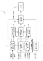
このロボットシミュレーション装置1は、図1に示されるように、ロボット本体20およびロボット本体20のアーム先端の取付面15に取り付けられるツール13を模擬する装置であって、ロボットの制御装置から出力されるハードウェア情報およびソフトウェア情報を読み込むロボット本体情報読込部2と、ロボット本体情報読込部2により読み込まれたハードウェア情報およびソフトウェア情報に基づいてロボット本体20の3次元モデルを生成するロボット本体モデル生成部(ロボットモデル生成部)3と、ツール13の情報を入力するツール情報入力部4と、ツール13を構成するハンド12の3次元モデルを記憶するハンドモデル記憶部5と、ツール情報入力部4により入力されたツール13の情報と、ハンドモデル記憶部5に記憶されたハンド12の3次元モデルと、ロボット本体モデル生成部3により生成されたロボット本体20の3次元モデルとに基づいて、ロボット本体20の取付面15にツール13を取り付けたロボットの3次元モデルを生成する模擬ロボット生成部6と、ツール13を動作させるための信号を設定する信号設定部7と、生成されたロボットの3次元モデルを用いて、ロボットのソフトウェア情報に含まれている動作プログラムを実行するプログラム実行部8と、実行結果を表示するモニタ9とを備えている。
As shown in FIG. 1, the
ロボットの制御装置から読み込まれる情報には、当該ロボットの識別情報、各軸の加速度、最高速度および動作範囲等のパラメータおよび動作プログラムが含まれている。
ロボット本体モデル生成部3は、ロボットから読み込まれたハードウェア情報に基づいて、ロボットシミュレーション装置1上で動作するロボット本体20の3次元モデルを生成し、各軸の加速度、最高速度および動作範囲を設定するようになっている。
The information read from the robot control device includes identification information of the robot, parameters such as acceleration of each axis, maximum speed, operation range, and operation program.
The robot body
ツール情報入力部4は、図1に示されるように、ツール13に備えられるハンド12の数と種類を設定するツール情報設定部10と、ロボットの取付面15にハンド12を取り付ける取付部材16の形状を設定する取付形状設定部(ハンド位置姿勢設定部)11とを備えている。
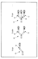
ツール情報設定部10は、図2に示されるように、異なる数のハンド12を有する複数種類のツール13をモニタ9上に表示してユーザに選択させることで、ツール13に備えられるハンド12の数を設定するようになっている。なお、ハンド12の数は、ユーザに数値入力させることにより設定してもよい。
As shown in FIG. 1, the tool
As shown in FIG. 2, the tool
また、ツール情報設定部10は、図3に示されるように、異なる種類のハンド12をモニタ9上に表示してユーザに選択させることで、ツール13に備えられるハンド12の種類を設定するようになっている。
ハンドモデル記憶部5には、ハンド12の種類を示す識別情報とハンド12の3次元モデルとが対応づけて記憶されており、ツール情報設定部10によりハンド12の種類が設定されると、ハンドモデル記憶部5に、当該種類に対応して記憶されているハンド12の3次元モデルが読み出されるようになっている。ハンドモデル記憶部5には、ハンド本体12aと該ハンド本体12aに適合する爪14の3次元モデルが別々に記憶されている。
Further, as shown in FIG. 3, the tool
In the hand
また、ツール情報設定部10は、ハンド12の種類が入力された後に、ハンド12に備えられる1以上の爪14の情報を設定するようになっている。ハンド12の種類が設定されることにより、ハンドモデル記憶部5に当該種類に対応して記憶されているハンド本体12aと、該ハンド本体12aに適合する爪14の3次元モデルが読み出されるようになっている。
The tool
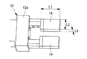
設定する爪14の情報としては、爪14の形状および寸法を挙げることができる。ハンドモデル記憶部5から読み出されたハンド本体12aに適合する爪14の形状を列挙してモニタ9に表示することで、所望の爪14の種類をユーザに選択させ、図4に示されるように、選択された種類の爪14を特定するための寸法(長さL1、幅L2、厚さL3等)をユーザに入力させるようになっている。
As the information of the nail | claw 14 to set, the shape and dimension of the nail | claw 14 can be mentioned. By enumerating and displaying on the
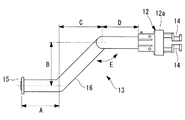
取付形状設定部11は、図5に示されるように、取付面15からハンド本体12aまでを結ぶ単純化された形状の取付部材16の寸法AからEをユーザに設定させるようになっている。これにより、ロボットの取付面15に対するハンド本体12aの位置および姿勢を設定することができるようになっている。
As shown in FIG. 5, the attachment
模擬ロボット生成部6は、図7に示されるように、選択されたハンド本体12aの3次元モデルと設定された取付部材16とを組み合わせたツール13の3次元モデルを生成するとともに、図8に示されるように、設定された爪14の3次元モデルをハンド本体12aの3次元モデルとは別個に生成する。また、模擬ロボット生成部6は、ロボット本体モデル生成部3により生成されたロボット本体20の3次元モデルの取付面15に、生成されたツール13の3次元モデルを取り付けたロボットの3次元モデルを生成するとともに、生成された爪14の3次元モデルをハンド本体12aに対して移動可能に組み合わせ、ツール座標系を設定するようになっている。模擬ロボット生成部6において、ツール座標系は、例えば、図6に示されるように、ハンド12に備えられる2以上の爪14の中央位置に設定されるようになっている。
As shown in FIG. 7, the simulated
信号設定部7は、図9に示されるように、ハンド12の各爪14と、各爪14を作動開始させるための出力信号および作動終了をロボット本体20に知らせるための入力信号との対応関係を設定するようになっている。図9においては3つの爪14(Claw1,Claw2,Claw3)の入出力信号と、移動距離および動作・動作時間が対応づけられている。
As shown in FIG. 9, the
このように構成された本実施形態に係るロボットシミュレーション装置1の作用について以下に説明する。
本実施形態に係るロボットシミュレーション装置1を用いてツール13を取り付けたロボットのシミュレーションを行うには、ロボット本体情報読込部2によってロボットの制御装置からロボット本体20の情報を読み込む。
The operation of the
In order to perform simulation of the robot to which the
これにより、ロボット本体情報読込部2により読み込まれたハードウェア情報に基づいて、ロボット本体モデル生成部3により、ロボット本体20の3次元モデルが生成される。
次いで、ユーザがツール情報入力部4によってツール13に備えられるハンド12の数および種類を入力する。これにより、入力された種類に対応するハンド12の3次元モデルが入力された数だけハンドモデル記憶部5から読み出される。
Thereby, based on the hardware information read by the robot body
Next, the user inputs the number and type of
ツール13に備えられるハンド12の種類が設定されると、設定された種類に対応してハンドモデル記憶部5に記憶されているハンド本体12aの3次元モデルと該ハンド本体12aに適合する爪14の3次元モデルとが読み出され、読み出された爪14の候補がモニタ9に表示されるので、ユーザがいずれかの爪14を選択すると、その爪14の寸法をユーザに入力させる画面が表示される。これに応じて、ユーザが爪14の寸法を入力することにより、所望の形状および大きさの爪14を有するハンド12の3次元モデルが生成される。
When the type of the
そして、ユーザが取付形状設定部11によって取付面15からハンド本体12aまでを結ぶ単純化された形状の取付部材16の寸法を設定すると、取付部材16の形状によって決定された取付面15に対する位置および姿勢で1以上のハンド本体12aがロボット本体20に固定され、ハンド本体12aに対して爪14が移動するロボットの3次元モデルが生成され、ハンド12の爪14の間に原点を有するツール座標系が設定される。
When the user sets the dimension of the mounting
次いで、ユーザは、信号設定部7により、ハンド12の各爪14と、各爪14を作動開始させるための出力信号および作動終了をロボット本体20に知らせるための入力信号との対応関係を設定する。これにより、ロボットの動作プログラムの各実行行に記述されている出力信号に対応してハンド12の爪14を動作させることができ、ハンド12の爪14の動作終了が入力信号として入力されたことを検出して次の実行行に移行することができるようになる。
Next, the user sets, by the
この後に、プログラム実行部8により、ロボットの制御部から読み込んだソフトウェア情報に含まれている動作プログラムを作動させること、および、モニタ9上においてロボットの3次元モデルを動作プログラムに従って動作させ、ロボットのシミュレーションを行うことができる。ロボットのシミュレーション結果としては、例えば、サイクルタイム、最大負荷、干渉有無および到達可不可が出力される。ユーザはサイクルタイムや最大負荷が、所定の基準より大きかったり、干渉が発生したり、動作範囲が足りなかったりする場合には、取付部材16の形状を変更したり、ハンド12の種類を変更したりして、全ての条件に適合するハンド12の位置および姿勢を評価することができる。
Thereafter, the
このように、本実施形態に係るロボットシミュレーション装置1によれば、周辺機器との干渉が発生した場合にハンド12の形状モデルを変形するのではなく、予め用意されたハンドモデルを用いてその位置や姿勢を変更してシミュレーションを行うので、周辺機器との干渉を回避しつつツール13の必要な機能を損なわないようにツール13を設計することができるという利点がある。
As described above, according to the
なお、本実施形態においては、信号設定部7により設定された入出力信号によって、動作プログラムに記述された出力信号によりハンド12の爪14を動作させることとしたが、図10(a)から(c)に示されるように、ハンド本体12aとしてロボット本体20の付加軸により動作する方式のものを採用し、ロボット本体20の他の駆動軸の作動指令と同様に、付加軸への作動指令によって爪14を駆動するハンド12を採用してもよい。
In the present embodiment, the
また、本実施形態においては、1以上のハンド12を有する単一のツール13の3次元モデルを生成して、ロボット本体20の取付面15に取り付けた状態のロボットの動作のシミュレーションを実施することとしたが、これに代えて、図11に示されるように、2以上のツール13の3次元モデルを生成して、ツール13を交換しながらシミュレーションを行うことにしてもよい。これにより、サイクルタイム、最大負荷、干渉有無および到達可不可等のシミュレーション結果をツール13間で比較して評価することができるという利点がある。
In the present embodiment, a three-dimensional model of a
1 ロボットシミュレーション装置
3 ロボット本体モデル生成部(ロボットモデル生成部)
5 ハンドモデル記憶部
7 信号設定部
10 ツール情報設定部
11 取付形状設定部(ハンド位置姿勢設定部)
12 ハンド
12a ハンド本体
13 ツール
14 爪
15 取付面
16 取付部材
1
5 Hand
12
Claims (7)
前記ハンドの種類と該ハンドの3次元モデルおよびツール座標系とを対応づけて記憶するハンドモデル記憶部と、
ユーザによる入力に基づき、前記ツールの前記1以上の前記ハンドの各々のロボットの取付面に対する位置および姿勢を設定するハンド位置姿勢設定部と、
前記ツール情報設定部により設定された前記ハンドの種類に基づいて前記ハンドモデル記憶部から読み出した前記ハンドの3次元モデルを前記ハンド位置姿勢設定部により設定された前記ハンドの位置および姿勢で前記取付面に取り付けた前記ロボットの3次元モデルを生成し、ツール座標系を設定するロボットモデル生成部とを備え、
該ロボットモデル生成部により生成された前記ロボットの3次元モデルおよび前記ツール座標系を用いて、前記ツールが前記取付面に取り付けられた前記ロボットのシミュレーションを行い、
該シミュレーションの後に、前記1以上のハンドの各々の前記取付面に対する位置および姿勢がユーザによる入力に基づいて前記ハンド位置姿勢設定部によって変更されるロボットシミュレーション装置。 A tool information setting unit for setting one or more types of hands provided in the tool;
A hand model storage unit that stores the type of the hand, the three-dimensional model of the hand, and the tool coordinate system in association with each other;
A hand position / posture setting unit that sets a position and a posture of each of the one or more hands of the tool with respect to a mounting surface of the robot based on an input by a user ;
The attachment of the three-dimensional model of the hand read from the hand model storage unit based on the type of the hand set by the tool information setting unit with the position and posture of the hand set by the hand position / posture setting unit A robot model generation unit that generates a three-dimensional model of the robot attached to a surface and sets a tool coordinate system;
Using the three-dimensional model of the robot generated by the robot model generation unit and the tool coordinate system, the robot with the tool attached to the attachment surface is simulated,
After the simulation, a robot simulation device in which the position and orientation of each of the one or more hands with respect to the mounting surface is changed by the hand position and orientation setting unit based on an input by a user .
前記ハンド位置姿勢設定部が、前記取付部材の形状を設定する請求項1に記載のロボットシミュレーション装置。 The tool includes the hand and an attachment member for attaching the hand to the robot,
The robot simulation apparatus according to claim 1, wherein the hand position / posture setting unit sets the shape of the attachment member.
前記ツール情報設定部が、前記爪の種類および大きさを設定する請求項1または請求項2に記載のロボットシミュレーション装置。 The hand includes a hand body and one or more nails that move relative to the hand body,
The robot simulation apparatus according to claim 1, wherein the tool information setting unit sets the type and size of the nail.
前記ロボットモデル生成部が、前記ツール情報設定部により設定されたいずれかの前記ツールを択一的に選択して前記ロボットのシミュレーションを行う請求項1から請求項6のいずれかに記載のロボットシミュレーション装置。
The tool information setting unit can set information of a plurality of the tools,
The robot simulation according to any one of claims 1 to 6, wherein the robot model generation unit selectively selects any of the tools set by the tool information setting unit and performs simulation of the robot. apparatus.
Priority Applications (3)
| Application Number | Priority Date | Filing Date | Title |
|---|---|---|---|
| JP2016173015A JP6571616B2 (en) | 2016-09-05 | 2016-09-05 | Robot simulation device |
| US15/676,109 US10603788B2 (en) | 2016-09-05 | 2017-08-14 | Robot simulation apparatus |
| CN201710769918.6A CN107791246B (en) | 2016-09-05 | 2017-08-31 | Robot simulation device |
Applications Claiming Priority (1)
| Application Number | Priority Date | Filing Date | Title |
|---|---|---|---|
| JP2016173015A JP6571616B2 (en) | 2016-09-05 | 2016-09-05 | Robot simulation device |
Publications (2)
| Publication Number | Publication Date |
|---|---|
| JP2018039060A JP2018039060A (en) | 2018-03-15 |
| JP6571616B2 true JP6571616B2 (en) | 2019-09-04 |
Family
ID=61281909
Family Applications (1)
| Application Number | Title | Priority Date | Filing Date |
|---|---|---|---|
| JP2016173015A Active JP6571616B2 (en) | 2016-09-05 | 2016-09-05 | Robot simulation device |
Country Status (3)
| Country | Link |
|---|---|
| US (1) | US10603788B2 (en) |
| JP (1) | JP6571616B2 (en) |
| CN (1) | CN107791246B (en) |
Families Citing this family (6)
| Publication number | Priority date | Publication date | Assignee | Title |
|---|---|---|---|---|
| JP6469159B2 (en) * | 2017-04-10 | 2019-02-13 | ファナック株式会社 | Offline programming apparatus and method with work position detection program generation function by contact sensor |
| WO2020178933A1 (en) * | 2019-03-04 | 2020-09-10 | 株式会社Fuji | Simulation system |
| JP6973444B2 (en) * | 2019-04-24 | 2021-11-24 | オムロン株式会社 | Control system, information processing device and control method |
| KR20210040613A (en) | 2019-10-04 | 2021-04-14 | 삼성전자주식회사 | Electronic apparatus and controlling method thereof |
| EP3838500A1 (en) * | 2019-12-17 | 2021-06-23 | Bystronic Laser AG | Construction of gripping tools for a laser cutting machine for absorbing parts |
| WO2024069929A1 (en) * | 2022-09-30 | 2024-04-04 | ファナック株式会社 | Display control device and program |
Family Cites Families (26)
| Publication number | Priority date | Publication date | Assignee | Title |
|---|---|---|---|---|
| JPS6071183A (en) | 1983-09-29 | 1985-04-23 | 三洋機工株式会社 | Method of detecting contact point of work gripping mechanism |
| US4613277A (en) * | 1984-04-16 | 1986-09-23 | Guay Roger G | Robotic head with interchangeable fingertips |
| JPH07104713B2 (en) | 1990-04-03 | 1995-11-13 | 株式会社神戸製鋼所 | Off-line teaching system for handling robot |
| JPH0560792U (en) | 1991-05-17 | 1993-08-10 | 株式会社コガネイ | Parallel hand device |
| JPH0569362A (en) | 1991-09-06 | 1993-03-23 | Toshiba Corp | Industrial robot |
| US5835693A (en) * | 1994-07-22 | 1998-11-10 | Lynch; James D. | Interactive system for simulation and display of multi-body systems in three dimensions |
| US5988862A (en) * | 1996-04-24 | 1999-11-23 | Cyra Technologies, Inc. | Integrated system for quickly and accurately imaging and modeling three dimensional objects |
| JP2003094367A (en) * | 2001-09-21 | 2003-04-03 | Ricoh Co Ltd | Robot hand with tip visual sense |
| JP3673749B2 (en) * | 2001-11-12 | 2005-07-20 | ファナック株式会社 | Simulation device |
| JP2004127190A (en) | 2002-10-07 | 2004-04-22 | Yaskawa Electric Corp | Robot design support device |
| JP3910134B2 (en) | 2002-10-30 | 2007-04-25 | ファナック株式会社 | Robot equipment |
| JP3708097B2 (en) * | 2003-10-08 | 2005-10-19 | ファナック株式会社 | Robot manual feeder |
| JP4669941B2 (en) | 2005-03-31 | 2011-04-13 | 国立大学法人北海道大学 | 3D design support device and program |
| US7478762B2 (en) * | 2005-08-05 | 2009-01-20 | Conlin Richard A | Thermal by-pass valve |
| JP2007334678A (en) | 2006-06-15 | 2007-12-27 | Fanuc Ltd | Robot simulation device |
| DE102006059829A1 (en) | 2006-12-15 | 2008-06-19 | Slawomir Suchy | Universal computer for performing all necessary functions of computer, has microprocessor, hard disk, main memory, monitor, digital versatile disc-compact disc-drive integrated in single computer device as components |
| JP2011185650A (en) * | 2010-03-05 | 2011-09-22 | Omron Corp | Model generation apparatus and model generation program |
| CN103221188B (en) * | 2010-11-17 | 2016-08-03 | 三菱电机株式会社 | Work-piece picking device |
| US8542124B2 (en) * | 2011-07-21 | 2013-09-24 | Axiom Technologies Inc. | Acoustic leak detector |
| JP5912474B2 (en) * | 2011-12-09 | 2016-04-27 | 川崎重工業株式会社 | Robot hand device |
| CN104470687A (en) * | 2012-07-20 | 2015-03-25 | 株式会社安川电机 | Robot simulator, robot teaching device and robot teaching method |
| JP6057862B2 (en) * | 2013-08-29 | 2017-01-11 | 三菱電機株式会社 | Component supply apparatus and program generation method for component supply apparatus |
| JP5788460B2 (en) * | 2013-11-05 | 2015-09-30 | ファナック株式会社 | Apparatus and method for picking up loosely stacked articles by robot |
| JP6036662B2 (en) * | 2013-11-22 | 2016-11-30 | 三菱電機株式会社 | Robot simulation apparatus, program, recording medium and method |
| JP2016020011A (en) | 2014-07-11 | 2016-02-04 | キヤノン株式会社 | Robot device and control method of robot device |
| JP6467854B2 (en) | 2014-10-15 | 2019-02-13 | 株式会社デンソーウェーブ | Gripping device |
-
2016
- 2016-09-05 JP JP2016173015A patent/JP6571616B2/en active Active
-
2017
- 2017-08-14 US US15/676,109 patent/US10603788B2/en active Active
- 2017-08-31 CN CN201710769918.6A patent/CN107791246B/en active Active
Also Published As
| Publication number | Publication date |
|---|---|
| US10603788B2 (en) | 2020-03-31 |
| US20180065249A1 (en) | 2018-03-08 |
| JP2018039060A (en) | 2018-03-15 |
| CN107791246A (en) | 2018-03-13 |
| CN107791246B (en) | 2022-04-08 |
Similar Documents
| Publication | Publication Date | Title |
|---|---|---|
| JP6571616B2 (en) | Robot simulation device | |
| US11458626B2 (en) | Trajectory generating method, and trajectory generating apparatus | |
| US9387589B2 (en) | Visual debugging of robotic tasks | |
| US7194396B2 (en) | Simulation device | |
| JP3946753B2 (en) | Robot program evaluation / correction method and robot program evaluation / correction device | |
| JP5512048B2 (en) | ROBOT ARM CONTROL DEVICE AND CONTROL METHOD, ROBOT, CONTROL PROGRAM, AND INTEGRATED ELECTRONIC CIRCUIT | |
| US10166673B2 (en) | Portable apparatus for controlling robot and method thereof | |
| US20150151431A1 (en) | Robot simulator, robot teaching device, and robot teaching method | |
| US9610690B2 (en) | Robot system for setting motion monitoring range of robot | |
| CN107530879B (en) | Multi-axis machine simulator, design support device for operation command device, design support device for motor control device, and motor capacity selection device | |
| JP7439206B2 (en) | Information processing methods, information processing devices, programs, recording media, production systems, robot systems, article manufacturing methods | |
| JP5113666B2 (en) | Robot teaching system and display method of robot operation simulation result | |
| JP6598454B2 (en) | Teaching data creation method, creation device, and creation program | |
| TW202024824A (en) | Machine tool system | |
| CN110682288A (en) | Robot program generating device | |
| JP2003150218A (en) | Simulation device | |
| JP6392817B2 (en) | Simulation device | |
| JP4829151B2 (en) | Robot program evaluation / correction method and robot program evaluation / correction device | |
| JP5272447B2 (en) | Numerical control machine operation simulator | |
| JPWO2019180916A1 (en) | Robot controller | |
| JP6913058B2 (en) | Machining simulation equipment | |
| JP2005301365A (en) | Operation controller equipped with simulator function | |
| JP6155570B2 (en) | Data display device, method, and program | |
| JP7276359B2 (en) | Motion command generation device, mechanism control system, computer program, motion command generation method, and mechanism control method | |
| CN116237928A (en) | Information processing apparatus, information processing system, information processing method, information processing program, and recording medium |
Legal Events
| Date | Code | Title | Description |
|---|---|---|---|
| A621 | Written request for application examination |
Free format text: JAPANESE INTERMEDIATE CODE: A621 Effective date: 20170919 |
|
| A977 | Report on retrieval |
Free format text: JAPANESE INTERMEDIATE CODE: A971007 Effective date: 20180920 |
|
| A131 | Notification of reasons for refusal |
Free format text: JAPANESE INTERMEDIATE CODE: A131 Effective date: 20180925 |
|
| A521 | Request for written amendment filed |
Free format text: JAPANESE INTERMEDIATE CODE: A523 Effective date: 20181120 |
|
| A131 | Notification of reasons for refusal |
Free format text: JAPANESE INTERMEDIATE CODE: A131 Effective date: 20190115 |
|
| A521 | Request for written amendment filed |
Free format text: JAPANESE INTERMEDIATE CODE: A523 Effective date: 20190313 |
|
| TRDD | Decision of grant or rejection written | ||
| A01 | Written decision to grant a patent or to grant a registration (utility model) |
Free format text: JAPANESE INTERMEDIATE CODE: A01 Effective date: 20190709 |
|
| A61 | First payment of annual fees (during grant procedure) |
Free format text: JAPANESE INTERMEDIATE CODE: A61 Effective date: 20190808 |
|
| R150 | Certificate of patent or registration of utility model |
Ref document number: 6571616 Country of ref document: JP Free format text: JAPANESE INTERMEDIATE CODE: R150 |