JP6557162B2 - Endoscope - Google Patents
Endoscope Download PDFInfo
- Publication number
- JP6557162B2 JP6557162B2 JP2016034400A JP2016034400A JP6557162B2 JP 6557162 B2 JP6557162 B2 JP 6557162B2 JP 2016034400 A JP2016034400 A JP 2016034400A JP 2016034400 A JP2016034400 A JP 2016034400A JP 6557162 B2 JP6557162 B2 JP 6557162B2
- Authority
- JP
- Japan
- Prior art keywords
- circuit board
- endoscope
- image sensor
- imaging device
- solid
- Prior art date
- Legal status (The legal status is an assumption and is not a legal conclusion. Google has not performed a legal analysis and makes no representation as to the accuracy of the status listed.)
- Active
Links
Images


Classifications
-
- A—HUMAN NECESSITIES
- A61—MEDICAL OR VETERINARY SCIENCE; HYGIENE
- A61B—DIAGNOSIS; SURGERY; IDENTIFICATION
- A61B1/00—Instruments for performing medical examinations of the interior of cavities or tubes of the body by visual or photographical inspection, e.g. endoscopes; Illuminating arrangements therefor
- A61B1/005—Flexible endoscopes
-
- G—PHYSICS
- G02—OPTICS
- G02B—OPTICAL ELEMENTS, SYSTEMS OR APPARATUS
- G02B23/00—Telescopes, e.g. binoculars; Periscopes; Instruments for viewing the inside of hollow bodies; Viewfinders; Optical aiming or sighting devices
- G02B23/24—Instruments or systems for viewing the inside of hollow bodies, e.g. fibrescopes
- G02B23/2476—Non-optical details, e.g. housings, mountings, supports
- G02B23/2484—Arrangements in relation to a camera or imaging device
-
- A—HUMAN NECESSITIES
- A61—MEDICAL OR VETERINARY SCIENCE; HYGIENE
- A61B—DIAGNOSIS; SURGERY; IDENTIFICATION
- A61B1/00—Instruments for performing medical examinations of the interior of cavities or tubes of the body by visual or photographical inspection, e.g. endoscopes; Illuminating arrangements therefor
- A61B1/00002—Operational features of endoscopes
- A61B1/00025—Operational features of endoscopes characterised by power management
-
- A—HUMAN NECESSITIES
- A61—MEDICAL OR VETERINARY SCIENCE; HYGIENE
- A61B—DIAGNOSIS; SURGERY; IDENTIFICATION
- A61B1/00—Instruments for performing medical examinations of the interior of cavities or tubes of the body by visual or photographical inspection, e.g. endoscopes; Illuminating arrangements therefor
- A61B1/00064—Constructional details of the endoscope body
- A61B1/00071—Insertion part of the endoscope body
- A61B1/0008—Insertion part of the endoscope body characterised by distal tip features
- A61B1/00096—Optical elements
-
- A—HUMAN NECESSITIES
- A61—MEDICAL OR VETERINARY SCIENCE; HYGIENE
- A61B—DIAGNOSIS; SURGERY; IDENTIFICATION
- A61B1/00—Instruments for performing medical examinations of the interior of cavities or tubes of the body by visual or photographical inspection, e.g. endoscopes; Illuminating arrangements therefor
- A61B1/00131—Accessories for endoscopes
-
- A—HUMAN NECESSITIES
- A61—MEDICAL OR VETERINARY SCIENCE; HYGIENE
- A61B—DIAGNOSIS; SURGERY; IDENTIFICATION
- A61B1/00—Instruments for performing medical examinations of the interior of cavities or tubes of the body by visual or photographical inspection, e.g. endoscopes; Illuminating arrangements therefor
- A61B1/00163—Optical arrangements
-
- A—HUMAN NECESSITIES
- A61—MEDICAL OR VETERINARY SCIENCE; HYGIENE
- A61B—DIAGNOSIS; SURGERY; IDENTIFICATION
- A61B1/00—Instruments for performing medical examinations of the interior of cavities or tubes of the body by visual or photographical inspection, e.g. endoscopes; Illuminating arrangements therefor
- A61B1/005—Flexible endoscopes
- A61B1/0051—Flexible endoscopes with controlled bending of insertion part
- A61B1/0055—Constructional details of insertion parts, e.g. vertebral elements
-
- A—HUMAN NECESSITIES
- A61—MEDICAL OR VETERINARY SCIENCE; HYGIENE
- A61B—DIAGNOSIS; SURGERY; IDENTIFICATION
- A61B1/00—Instruments for performing medical examinations of the interior of cavities or tubes of the body by visual or photographical inspection, e.g. endoscopes; Illuminating arrangements therefor
- A61B1/04—Instruments for performing medical examinations of the interior of cavities or tubes of the body by visual or photographical inspection, e.g. endoscopes; Illuminating arrangements therefor combined with photographic or television appliances
- A61B1/05—Instruments for performing medical examinations of the interior of cavities or tubes of the body by visual or photographical inspection, e.g. endoscopes; Illuminating arrangements therefor combined with photographic or television appliances characterised by the image sensor, e.g. camera, being in the distal end portion
- A61B1/051—Details of CCD assembly
-
- A—HUMAN NECESSITIES
- A61—MEDICAL OR VETERINARY SCIENCE; HYGIENE
- A61B—DIAGNOSIS; SURGERY; IDENTIFICATION
- A61B1/00—Instruments for performing medical examinations of the interior of cavities or tubes of the body by visual or photographical inspection, e.g. endoscopes; Illuminating arrangements therefor
- A61B1/06—Instruments for performing medical examinations of the interior of cavities or tubes of the body by visual or photographical inspection, e.g. endoscopes; Illuminating arrangements therefor with illuminating arrangements
- A61B1/0661—Endoscope light sources
-
- G—PHYSICS
- G02—OPTICS
- G02B—OPTICAL ELEMENTS, SYSTEMS OR APPARATUS
- G02B23/00—Telescopes, e.g. binoculars; Periscopes; Instruments for viewing the inside of hollow bodies; Viewfinders; Optical aiming or sighting devices
- G02B23/24—Instruments or systems for viewing the inside of hollow bodies, e.g. fibrescopes
- G02B23/2407—Optical details
- G02B23/2423—Optical details of the distal end
-
- G—PHYSICS
- G02—OPTICS
- G02B—OPTICAL ELEMENTS, SYSTEMS OR APPARATUS
- G02B23/00—Telescopes, e.g. binoculars; Periscopes; Instruments for viewing the inside of hollow bodies; Viewfinders; Optical aiming or sighting devices
- G02B23/24—Instruments or systems for viewing the inside of hollow bodies, e.g. fibrescopes
- G02B23/2407—Optical details
- G02B23/2446—Optical details of the image relay
-
- G—PHYSICS
- G02—OPTICS
- G02B—OPTICAL ELEMENTS, SYSTEMS OR APPARATUS
- G02B23/00—Telescopes, e.g. binoculars; Periscopes; Instruments for viewing the inside of hollow bodies; Viewfinders; Optical aiming or sighting devices
- G02B23/24—Instruments or systems for viewing the inside of hollow bodies, e.g. fibrescopes
- G02B23/2407—Optical details
- G02B23/2461—Illumination
- G02B23/2469—Illumination using optical fibres
Description
本発明は、内視鏡に関する。 The present invention relates to an endoscope.
内視鏡の挿入部の先端部に搭載される撮像装置は、一般に、イメージセンサと、イメージセンサが実装される回路基板とを備え、挿入部に挿通された複数の電線が回路基板に接続される。 An imaging device mounted at the distal end portion of an insertion portion of an endoscope generally includes an image sensor and a circuit board on which the image sensor is mounted, and a plurality of wires inserted through the insertion portion are connected to the circuit board. The
特許文献1に記載された撮像装置は、イメージセンサと回路基板とを覆うケース部材(カバー部材)を有している。
The imaging device described in
イメージセンサと回路基板との接続を保護し、且つ、回路基板と電線との接続の耐久性を高める上では、イメージセンサから回路基板と電線との接続部までを含む範囲を剛性の高いケース部材で覆うことが望ましい。しかし、イメージセンサと回路基板の全体をケース部材で覆う構成においては、イメージセンサに対する回路基板の取り付け位置に誤差が生じると、イメージセンサと回路基板をケース部材に収容できなくなる場合がある。なお、取り付け位置の誤差を見込んでケース部材の寸法を大きめに選定すると、撮像装置の大型化を招き、内視鏡の挿入部の細径化を阻害してしまうため好ましくない。 In order to protect the connection between the image sensor and the circuit board and increase the durability of the connection between the circuit board and the electric wire, the case member having a high rigidity is included in the range including the connection portion between the image sensor and the circuit board and the electric wire. It is desirable to cover with. However, in the configuration in which the entire image sensor and the circuit board are covered with the case member, if an error occurs in the mounting position of the circuit board with respect to the image sensor, the image sensor and the circuit board may not be accommodated in the case member. Note that it is not preferable to select a large case member size in consideration of an attachment position error because the size of the imaging apparatus is increased and the diameter of the insertion portion of the endoscope is hindered.
本発明は、上述した事情に鑑みなされたものであり、イメージセンサに対する回路基板の取り付け位置に誤差が生じてもこのイメージセンサと回路基板をケース部材に収容可能な内視鏡を提供することを目的とする。 The present invention has been made in view of the above-described circumstances, and provides an endoscope capable of accommodating the image sensor and the circuit board in a case member even if an error occurs in the mounting position of the circuit board with respect to the image sensor. Objective.
本発明は下記構成からなる。
体腔内に挿入される挿入部の先端部に撮像装置を備えた内視鏡であって、
前記撮像装置は、
受像面が前記挿入部の長手方向に交差するよう配置され、前記受像面にて結像された光学画像を光電変換する固体撮像素子と、
前記固体撮像素子の前記受像面とは反対側の端子が設けられた面に対向し、前記固体撮像素子の前記端子と電気的に接続する接続面を有したリジッド回路基板と、
前記固体撮像素子及び前記回路基板の一部を覆うカバー部を含むケース部材と、を有し、
前記リジッド回路基板は、前記挿入部の長手方向に直交する幅方向の長さがそれぞれ異なる幅広部及び幅狭部を有し、
前記カバー部は、一対の側壁と前記一対の側壁に架け渡された天井壁を有し、前記一対の側壁には、前記幅方向に見て、前記リジッド回路基板の前記幅広部と直交する方向で前記幅広部と対応する位置に第1切欠部が設けられた、内視鏡。
The present invention has the following configuration.
An endoscope including an imaging device at a distal end portion of an insertion portion to be inserted into a body cavity
The imaging device
A solid-state imaging device that is arranged so that an image receiving surface intersects with a longitudinal direction of the insertion portion, and photoelectrically converts an optical image formed on the image receiving surface;
A rigid circuit board having a connection surface facing a surface provided with a terminal opposite to the image receiving surface of the solid-state image sensor and electrically connected to the terminal of the solid-state image sensor;
A case member including a cover portion covering a part of the solid-state imaging device and the circuit board,
The rigid circuit board has a wide part and a narrow part with different lengths in the width direction perpendicular to the longitudinal direction of the insertion part,
The cover portion has a pair of side walls and a ceiling wall spanned between the pair of side walls, and the pair of side walls has a direction orthogonal to the wide portion of the rigid circuit board when viewed in the width direction. An endoscope in which a first cutout is provided at a position corresponding to the wide portion.
本発明によれば、リジッド回路基板は幅広部及び幅狭部を有し、ケース部材のカバー部の一対の側壁には、挿入部の長手方向に直交する幅方向に見て、幅広部と直交する方向でこの幅広部と対応する位置に第1切欠部が設けられているため、イメージセンサに対する回路基板の取り付け位置に誤差が生じても、イメージセンサと回路基板をケース部材に収容できる。その結果、取り付け位置の誤差を見込んでケース部材の寸法を大きめに選定する必要がないため、内視鏡の挿入部の細径化が可能であり、かつ、ケース部材による撮像装置の耐久性を高めることができる。 According to the present invention, the rigid circuit board has a wide portion and a narrow portion, and the pair of side walls of the cover portion of the case member is orthogonal to the wide portion when viewed in the width direction orthogonal to the longitudinal direction of the insertion portion. Since the first cutout portion is provided at a position corresponding to the wide portion in the direction in which the image sensor is mounted, the image sensor and the circuit board can be accommodated in the case member even if an error occurs in the mounting position of the circuit board with respect to the image sensor. As a result, it is not necessary to select a large case member dimension in view of the attachment position error, so that the diameter of the insertion portion of the endoscope can be reduced, and the durability of the imaging device by the case member can be increased. Can be increased.
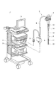
図1は、本発明の実施形態を説明するための、内視鏡システムの一例を示す。 FIG. 1 shows an example of an endoscope system for explaining an embodiment of the present invention.
内視鏡システム1は、内視鏡2と、光源ユニット3と、プロセッサユニット4とを備える。内視鏡2は、被検体内に挿入される挿入部6と、挿入部6に連なる操作部7と、操作部7から延びるユニバーサルコード8とを有し、挿入部6は、先端部10と、先端部10に連なる湾曲部11と、湾曲部11と操作部7とを繋ぐ軟性部12とで構成されている。
The
先端部10には、観察部位を照明するための照明光を出射する照明光学系や、観察部位を撮像する撮像装置及び撮像光学系などが設けられている。湾曲部11は挿入部6の長手軸と直交する方向に湾曲可能に構成されており、湾曲部11の湾曲動作は操作部7にて操作される。また、軟性部12は、挿入部6の挿入経路の形状に倣って変形可能な程に比較的柔軟に構成されている。
The
操作部7には、先端部10の撮像装置の撮像動作を操作するボタンや、湾曲部11の湾曲動作を操作するノブなどが設けられている。また、操作部7には、電気メスなどの処置具が導入される導入口13が設けられており、挿入部6の内部には、導入口13から先端部10に達し、処置具が挿通される処置具チャンネル14が設けられている。
The
ユニバーサルコード8の末端にはコネクタ9が設けられ、内視鏡2は、コネクタ9を介して、先端部10の照明光学系から出射される照明光を生成する光源ユニット3、及び先端部10の撮像装置によって取得される映像信号を処理するプロセッサユニット4と接続される。プロセッサユニット4は、入力された映像信号を処理して観察部位の映像データを生成し、生成した映像データをモニタ5に表示させ、また記録する。
A
挿入部6及び操作部7並びにユニバーサルコード8の内部にはライトガイドや電線群が収容されている。光源ユニット3にて生成された照明光がライトガイドを介して先端部10の照明光学系に導光され、先端部10の撮像装置とプロセッサユニット4との間で信号や電力が電線群を介して伝送される。
A light guide and a wire group are accommodated in the
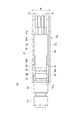
図2から図6は、挿入部6の先端部10に搭載された撮像装置の構成を示す。
2 to 6 show the configuration of the imaging device mounted on the
撮像装置20は、CCD(Charge Coupled Device)イメージセンサやCMOS(Complementaly Metal Oxide Semiconductor)イメージセンサなどのイメージセンサ(固体撮像素子)21と、イメージセンサ21の受像面21aに被写体像を結像させる撮像光学系を収納した鏡筒22と、イメージセンサ21及び鏡筒22を保持したセンサホルダ23と、イメージセンサ21が実装された回路基板24と、イメージセンサ21及び回路基板24の一部を覆うケース部材28と、を備える。
The
センサホルダ23は、撮像光学系の光軸B(図6)に沿って移動可能に鏡筒22を保持しており、鏡筒22が移動されて撮像光学系に対するイメージセンサ21の位置が調整可能となっている。鏡筒22は、イメージセンサ21の位置決めがなされた後に、例えば接着剤などによってセンサホルダ23に固定される。
The
イメージセンサ21は、その受像面21aが挿入部6の長手方向に交差して配置され、受像面21aにて結像された光学画像を光電変換する。受像面21aの法線方向に見た場合のイメージセンサ21の外径は1mm四方以下である。イメージセンサ21の受像面21aとは反対側の背面には信号や電力が入出力される複数の端子26が設けられている。
The
回路基板24は、センサ接続部30と、電線接続部31とを有する。センサ接続部30は、イメージセンサ21の受像面21aとは反対側の端子26が設けられた面に対向し、イメージセンサ21の端子26と電気的に接続する接続面30aを有している。
The
センサ接続部30の接続面30aには複数のランド25が形成されている。センサ接続部30はイメージセンサ21の背面に添えられ、イメージセンサ21の背面に設けられた端子26がセンサ接続部30のランド25に接続されている。
A plurality of
回路基板24は、挿入部6の長手方向に直交する幅方向(図4の矢印Wの方向)に見てL字状に形成されたリジッド回路基板であって、センサ接続部30と電線接続部31とは略直交している。すなわち、本実施形態では、回路基板24を構成する2つの脚部のうちの一方がセンサ接続部30を構成し、他方が電線接続部31を構成している。センサ接続部30は、イメージセンサ21の背面に添えられてイメージセンサ21の受像面21aと平行に配置されている。電線接続部31は受像面21aと略垂直に配置され、イメージセンサ21の背後で受像面21aの法線方向に延びている。なお、回路基板24はフレキシブル回路基板であってもよい。
The
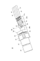
電線接続部31にもまた複数のランド32が形成されており、電線接続部31の基板面に沿って平面状に並べられた複数の電線27それぞれの端末部の先端部分に露出された中心導体が電線接続部31のランド32に接続されている。回路基板24及び回路基板24に実装されたイメージセンサ21は、複数の電線27を介してプロセッサユニット4に接続されている。なお、複数の電線27によって伝送ケーブルが構成されている。
A plurality of
回路基板24は、挿入部6の長手方向に直交する幅方向(図4の矢印Wの方向)の長さがそれぞれ異なる幅広部24A及び幅狭部24Bを有している。幅広部24Aは、電線接続部31の電線27が接続される側の端部31aからセンサ接続部30の近傍に至る部分に形成されている。回路基板24の幅広部24A以外の部分が幅狭部24Bを形成し、センサ接続部30は幅狭部24Bに属する。
The
ケース部材28は、複数の電線27を保持する保持部33と、イメージセンサ21及び回路基板24の一部を覆うカバー部34とを有する。
The
カバー部34は、一対の側壁35及び一対の側壁35に架け渡された天井壁36によって構成されている。
The
一対の側壁35は、イメージセンサ21の受像面21aの法線に沿う回路基板24の一対の側面に沿って設けられている。一対の側壁35の各々には、挿入部6の長手方向に直交する幅方向(図4の矢印Wの方向)に見て、回路基板24の幅広部24Aと干渉せずに、幅広部24Aと直交する方向で幅広部24Aと対応する位置に第1切欠部51が設けられている。また、回路基板24の幅狭部24Bの一部は、イメージセンサ21側に延びる一対の側壁35によって隙間D(図4)を介して幅方向(矢印W方向)に挟まれている。一対の側壁35は、イメージセンサ21側の各先端部が接着剤などによってセンサホルダ23に固定される。
The pair of
天井壁36は、回路基板24の電線接続部31のランド32が形成されている基板面、及びランド32に接続された電線27の端末部を覆っている。天井壁36の、回路基板24の接続面30aが設けられた脚部、すなわちセンサ接続部30の端部側には、第2切欠部52が設けられている。第2切欠部52は、天井壁36のセンサ接続部30に対応する位置からイメージセンサ21側に設けられている。
The
保持部33は、カバー部34の一対の側壁35それぞれに設けられた一対の延長側壁37によって構成されている。一対の延長側壁37は、イメージセンサ21の受像面21aの法線に沿ってカバー部34の後方に延びており、回路基板24の電線接続部31の基板面に沿って平面状に並ぶ複数の電線27を並び方向に挟んで配置されている。
The holding
一対の延長側壁37それぞれの先端部には押え片38が設けられており、押え片38は、一対の延長側壁37の間に挟まれた複数の電線27に電線接続部31の基板面とは反対側から重なって配置されている。これにより、電線接続部31の基板面上での複数の電線27の平面状の並びが、電線接続部31の後方においても維持される。
A holding
複数の電線27に重なった押え片38は、カバー部34の天井壁36よりも電線接続部31側に寄って配置されており、押え片38と天井壁36との間には段差が形成されている。
The
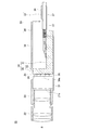
図7及び図8は、撮像装置20が搭載された挿入部6の先端部10、及び湾曲部11の構成を示す。
7 and 8 show the configuration of the
先端部10には、上記の撮像装置20と、処置具チャンネル14の先端部とが設けられており、また、ライトガイド40を介して光源ユニット3から導光される照明光を出射する照明光学系なども設けられる。
The
イメージセンサ21及び鏡筒22を保持したセンサホルダ23は、例えばステンレス鋼材などの金属材料からなる先端硬質部41に形成された収容孔に収容され、先端硬質部41に固定されている。処置具チャンネル14の先端部や照明光学系もまた、先端硬質部41に形成された収容孔にそれぞれ収容され、先端硬質部41に固定されている。
The
先端硬質部41に固定されたセンサホルダ23によって保持されているイメージセンサ21の受像面21aは挿入部6の長手軸Aに対して略垂直に配置されており、受像面21aに対して略垂直な電線接続部31は長手軸Aに沿って配置されている。
The
湾曲部11は、長手軸Aに沿って並ぶ複数の環状の駒42を含み、これらの駒42により、撮像装置20の回路基板24に接続された複数の電線27や処置具チャンネル14やライトガイド40などを収容する管体として構成されている。
The bending
隣り合う二つの駒42は、長手軸Aに略直交する軸線上に配置された一対のピン43によって軸線まわりに回動可能に連結されている。隣り合う二つの駒42の個々の回動が合わさることによって、湾曲部11は全体として湾曲する。
Two
湾曲部11は、操作部7から軟性部12(図1参照)を経て湾曲部11に挿通された一対のワイヤ44によって動作される。操作部7での操作に伴い、一対のワイヤ44のうち一方のワイヤ44が牽引され、他方のワイヤ44が繰り出され、これにより湾曲部11は動作されて湾曲する。
The bending
湾曲部11を構成する複数の駒42のうち、先端部10側の先頭の駒42が先端部10の先端硬質部41に接合され、先端部10と湾曲部11とは接続されている。センサホルダ23が先端硬質部41に固定された撮像装置20の回路基板24及びケース部材28は、挿入部6において挿入部6の軸方向に先端部10に隣接する部位である先頭の駒42の内側に配置されている。
Of the plurality of
先頭の駒42と先頭の駒42に隣り合う駒42とを連結している一対のピン43それぞれの頭部43aは、これらの駒42の内径側に突出している。一対のピン43の間は、挿入部6の軸方向と直交する一対のピン43の対向方向に狭窄しており、対向方向と平行な方向の挿入部6の内径が一対のピン43の配置箇所を挿入部6の軸方向に挟み込む前後の箇所より小さい狭窄部となっている。
The
先頭の駒42の内側に配置されているケース部材28の保持部33は、挿入部6の内部の狭窄部である一対のピン43の間に配置されており、一対のピン43の間で、回路基板24の電線接続部31に接続された複数の電線27を保持している。
The holding
上記説明した本実施形態によれば、回路基板24は、挿入部6の長手方向に直交する幅方向(図4の矢印Wの方向)の長さがそれぞれ異なる幅広部24A及び幅狭部24Bを有し、ケース部材28のカバー部34の一対の側壁35には、回路基板24の幅広部24Aと対応する位置に第1切欠部51が設けられている。このため、イメージセンサ21に対する回路基板24の取り付け位置に、図4に示す矢印Wの方向の誤差が生じても、回路基板24の幅広部24Aとケース部材28とが干渉せずに、イメージセンサ21と回路基板24をケース部材28に収容できる。また、ケース部材28のカバー部34の天井壁36には、センサ接続部30に対応する位置からイメージセンサ21側に第2切欠部52が設けられている。このため、イメージセンサ21に対する回路基板24の取り付け位置に、図4に示す矢印Wに垂直な天井壁36方向の誤差が生じても、回路基板24とケース部材28とが干渉せずに、イメージセンサ21と回路基板24をケース部材28に収容できる。その結果、取付位置の誤差を見込んでケース部材28の寸法を大きめに選定する必要がないため、内視鏡2の挿入部6の細径化が可能であり、かつ、ケース部材28による撮像装置20の耐久性を高めることができる。特に本実施形態ではイメージセンサ21の外径が1mm四方以下であり、撮像装置20の寸法に高い精度が求められるが、上述したように回路基板24とケース部材28とが干渉しないため、撮像装置20を高い精度で小型化できる。
According to the present embodiment described above, the
また、回路基板24には、複数の電線27が幅広部24Aに接続されているので、回路基板24と電線27との電気的接続部であるランド32の面積を小さくする必要がない。よって、回路基板24に対する複数の電線27の接続強度の低下を招くことはない。
In addition, since the plurality of
また、回路基板24の幅狭部24Bの一部がケース部材28の一対の側壁35によって隙間D(図4)を介して挟まれているので、イメージセンサ21に対する回路基板24の取り付け時に、図4に示す矢印Wの方向に隙間D分の誤差が生じても、この誤差は隙間Dの存在により許容される。
In addition, since a part of the
なお、本実施形態では、回路基板24がL字状に形成されているが、その他の形状、例えば平板状の回路基板24を採用することも可能である。
In the present embodiment, the
以上説明したとおり、本明細書に開示された内視鏡は、体腔内に挿入される挿入部の先端部に撮像装置を備えた内視鏡であって、上記撮像装置は、受像面にて結像された光学画像を光電変換する固体撮像素子と、上記固体撮像素子の上記受像面とは反対側の端子が設けられた面に対向し、上記固体撮像素子の上記端子と電気的に接続する接続面を有した回路基板と、上記固体撮像素子及び上記回路基板の一部を覆うケース部材と、を有し、上記回路基板は、上記挿入部の長手方向に直交する幅方向の長さがそれぞれ異なる幅広部及び幅狭部を有し、上記ケース部材には、上記幅方向に見て、上記回路基板の上記幅広部と直交する方向で上記幅広部と対応する位置に第1切欠部が設けられている。 As described above, the endoscope disclosed in the present specification is an endoscope provided with an imaging device at the distal end portion of an insertion portion to be inserted into a body cavity, and the imaging device is configured on an image receiving surface. A solid-state image sensor that photoelectrically converts the formed optical image and a surface provided with a terminal opposite to the image receiving surface of the solid-state image sensor, and electrically connected to the terminal of the solid-state image sensor A circuit board having a connection surface and a case member that covers a part of the solid-state imaging device and the circuit board, and the circuit board has a length in a width direction orthogonal to a longitudinal direction of the insertion portion. Each of the case member has a first notch at a position corresponding to the wide portion in a direction orthogonal to the wide portion of the circuit board as viewed in the width direction. Is provided.
また、上記回路基板の上記幅広部に、伝送ケーブルが電気的に接続される。 A transmission cable is electrically connected to the wide portion of the circuit board.
また、上記固体撮像素子は、上記受像面が上記挿入部の長手方向に交差するよう配置され、上記回路基板が、上記幅方向に見てL字状に形成され、上記回路基板を構成する2つの脚部のうちの1つに上記接続面が設けられ、上記ケース部材の上記接続面が設けられた脚部の端部側には第2切欠部が設けられている。 Further, the solid-state imaging device is arranged so that the image receiving surface intersects the longitudinal direction of the insertion portion, and the circuit board is formed in an L shape when viewed in the width direction, and constitutes the circuit board. One of the two leg portions is provided with the connection surface, and a second notch portion is provided on an end portion side of the case member on which the connection surface is provided.
また、上記回路基板の上記幅狭部の少なくとも一部が、上記ケース部材によって隙間を介して上記幅方向に挟まれている。 Further, at least a part of the narrow portion of the circuit board is sandwiched in the width direction by the case member via a gap.
また、上記固体撮像素子の上記受像面の法線方向に見た場合の上記固体撮像素子の外径は1mm四方以下である。 Moreover, the outer diameter of the solid-state image sensor when viewed in the normal direction of the image receiving surface of the solid-state image sensor is 1 mm square or less.
1 内視鏡システム
2 内視鏡
20 撮像装置
21 イメージセンサ
21a 受像面
22 鏡筒(撮像光学系)
23 センサホルダ
24 回路基板
24A 幅広部
24B 幅狭部
26 端子
27 電線
28 ケース部材
30 センサ接続部
30a 接続面
31 電線接続部
33 保持部
34 カバー部
51 第1切欠部
52 第2切欠部
DESCRIPTION OF
23
Claims (5)
前記撮像装置は、
受像面が前記挿入部の長手方向に交差するよう配置され、前記受像面にて結像された光学画像を光電変換する固体撮像素子と、
前記固体撮像素子の前記受像面とは反対側の端子が設けられた面に対向し、前記固体撮像素子の前記端子と電気的に接続する接続面を有したリジッド回路基板と、
前記固体撮像素子及び前記回路基板の一部を覆うカバー部を含むケース部材と、を有し、
前記リジッド回路基板は、前記挿入部の長手方向に直交する幅方向の長さがそれぞれ異なる幅広部及び幅狭部を有し、
前記カバー部は、一対の側壁と前記一対の側壁に架け渡された天井壁を有し、前記一対の側壁には、前記幅方向に見て、前記リジッド回路基板の前記幅広部と直交する方向で前記幅広部と対応する位置に第1切欠部が設けられた、内視鏡。 An endoscope including an imaging device at a distal end portion of an insertion portion to be inserted into a body cavity,
The imaging device
A solid-state imaging device that is arranged so that an image receiving surface intersects with a longitudinal direction of the insertion portion, and photoelectrically converts an optical image formed on the image receiving surface;
A rigid circuit board having a connection surface facing a surface provided with a terminal opposite to the image receiving surface of the solid-state image sensor and electrically connected to the terminal of the solid-state image sensor;
A case member including a cover portion covering a part of the solid-state imaging device and the circuit board,
The rigid circuit board has a wide part and a narrow part with different lengths in the width direction perpendicular to the longitudinal direction of the insertion part,
The cover portion has a pair of side walls and a ceiling wall spanned between the pair of side walls, and the pair of side walls has a direction orthogonal to the wide portion of the rigid circuit board when viewed in the width direction. An endoscope in which a first cutout is provided at a position corresponding to the wide portion.
前記リジッド回路基板の前記幅広部には、伝送ケーブルが電気的に接続される、内視鏡。 The endoscope according to claim 1, wherein
An endoscope, wherein a transmission cable is electrically connected to the wide portion of the rigid circuit board.
前記リジッド回路基板は、前記幅方向に見てL字状に形成され、
前記リジッド回路基板を構成するL字の2つの脚部のうちの1つに前記接続面が設けられ、
前記天井壁の前記接続面が設けられた脚部の端部側には第2切欠部が設けられた、内視鏡。 The endoscope according to claim 1 or 2,
The rigid circuit board is formed in an L shape when viewed in the width direction,
The connection surface is provided on one of two L-shaped leg portions constituting the rigid circuit board,
An endoscope in which a second cutout portion is provided on an end side of a leg portion provided with the connection surface of the ceiling wall .
前記回路基板の前記幅狭部の少なくとも一部は、前記一対の側壁によって隙間を介して前記幅方向に挟まれた、内視鏡。 The endoscope according to any one of claims 1 to 3,
An endoscope in which at least a part of the narrow portion of the circuit board is sandwiched in the width direction by a pair of side walls through a gap.
前記固体撮像素子の前記受像面の法線方向に見た場合の前記固体撮像素子の外径は1mm四方以下である、内視鏡。 The endoscope according to any one of claims 1 to 4,
An endoscope, wherein the solid-state image sensor has an outer diameter of 1 mm square or less when viewed in the normal direction of the image receiving surface of the solid-state image sensor.
Priority Applications (4)
| Application Number | Priority Date | Filing Date | Title |
|---|---|---|---|
| JP2016034400A JP6557162B2 (en) | 2016-02-25 | 2016-02-25 | Endoscope |
| US15/433,976 US10591713B2 (en) | 2016-02-25 | 2017-02-15 | Endoscope having an imaging unit |
| EP17156422.2A EP3210523A1 (en) | 2016-02-25 | 2017-02-16 | Endoscope |
| CN201710099444.9A CN107115088B (en) | 2016-02-25 | 2017-02-23 | Endoscope with a detachable handle |
Applications Claiming Priority (1)
| Application Number | Priority Date | Filing Date | Title |
|---|---|---|---|
| JP2016034400A JP6557162B2 (en) | 2016-02-25 | 2016-02-25 | Endoscope |
Publications (2)
| Publication Number | Publication Date |
|---|---|
| JP2017148298A JP2017148298A (en) | 2017-08-31 |
| JP6557162B2 true JP6557162B2 (en) | 2019-08-07 |
Family
ID=58054040
Family Applications (1)
| Application Number | Title | Priority Date | Filing Date |
|---|---|---|---|
| JP2016034400A Active JP6557162B2 (en) | 2016-02-25 | 2016-02-25 | Endoscope |
Country Status (4)
| Country | Link |
|---|---|
| US (1) | US10591713B2 (en) |
| EP (1) | EP3210523A1 (en) |
| JP (1) | JP6557162B2 (en) |
| CN (1) | CN107115088B (en) |
Families Citing this family (2)
| Publication number | Priority date | Publication date | Assignee | Title |
|---|---|---|---|---|
| WO2018198266A1 (en) * | 2017-04-27 | 2018-11-01 | オリンパス株式会社 | Endoscope, imaging module, and method for manufacturing imaging module |
| CN110445959B (en) * | 2018-05-04 | 2021-05-07 | 致伸科技股份有限公司 | Method for assembling camera module |
Family Cites Families (24)
| Publication number | Priority date | Publication date | Assignee | Title |
|---|---|---|---|---|
| FR2737650B1 (en) | 1995-08-07 | 1997-11-28 | Tokendo Sarl | VIDEOENDOSCOPE |
| JP2000210252A (en) * | 1999-01-25 | 2000-08-02 | Sony Corp | Solid imaging device |
| JP2000232957A (en) * | 1999-02-15 | 2000-08-29 | Olympus Optical Co Ltd | Endoscopic device |
| JP4377821B2 (en) | 2005-01-17 | 2009-12-02 | オリンパス株式会社 | Endoscope electrical connector, endoscope, and assembly method of electrical connector |
| WO2006075744A1 (en) | 2005-01-17 | 2006-07-20 | Olympus Corporation | Endoscope electric connector, endoscope, and electric connector assembling method |
| JP5154783B2 (en) * | 2006-11-14 | 2013-02-27 | オリンパス株式会社 | Manufacturing method of imaging module |
| US9901244B2 (en) * | 2009-06-18 | 2018-02-27 | Endochoice, Inc. | Circuit board assembly of a multiple viewing elements endoscope |
| EP2371262B1 (en) * | 2009-07-23 | 2017-03-29 | Olympus Corporation | Endoscope apparatus |
| US20140320621A1 (en) * | 2009-09-16 | 2014-10-30 | Medigus Ltd. | Small diameter video camera heads and visualization probes and medical devices containing them |
| JP5452282B2 (en) * | 2010-02-26 | 2014-03-26 | オリンパス株式会社 | Solid-state imaging device |
| US8698887B2 (en) * | 2010-04-07 | 2014-04-15 | Olympus Corporation | Image pickup apparatus, endoscope and manufacturing method for image pickup apparatus |
| JP2012055489A (en) * | 2010-09-08 | 2012-03-22 | Fujifilm Corp | Imaging device for electronic endoscope and manufacturing method of imaging device |
| WO2012033936A2 (en) * | 2010-09-08 | 2012-03-15 | Tyco Healthcare Group Lp | Catheter with imaging assembly |
| JP5436470B2 (en) * | 2011-01-31 | 2014-03-05 | 富士フイルム株式会社 | Imaging device and electronic endoscope provided with the same |
| US9101266B2 (en) * | 2011-02-07 | 2015-08-11 | Endochoice Innovation Center Ltd. | Multi-element cover for a multi-camera endoscope |
| JP5192559B2 (en) * | 2011-02-24 | 2013-05-08 | 富士フイルム株式会社 | Endoscope |
| TWM421800U (en) * | 2011-08-05 | 2012-02-01 | Limit Optics Co Ltd | Endoscope device having flexible printed circuit board |
| WO2013105921A1 (en) * | 2011-12-12 | 2013-07-18 | Optoelectronics Co., Ltd. | Miniature imaging and decoding module |
| WO2014065099A1 (en) * | 2012-10-23 | 2014-05-01 | オリンパス株式会社 | Imaging device, endoscope, semiconductor device, and method of manufacturing semiconductor device |
| JP2015058118A (en) | 2013-09-18 | 2015-03-30 | パナソニック株式会社 | Endoscope |
| JP6431698B2 (en) * | 2014-06-16 | 2018-11-28 | オリンパス株式会社 | Imaging unit, wiring board with cable, and method of manufacturing wiring board with cable |
| WO2016143179A1 (en) * | 2015-03-10 | 2016-09-15 | オリンパス株式会社 | Imaging apparatus for endoscope |
| WO2016157376A1 (en) * | 2015-03-30 | 2016-10-06 | オリンパス株式会社 | Image pickup device and endoscope |
| CN106356663B (en) * | 2015-07-14 | 2020-04-24 | 富士康(昆山)电脑接插件有限公司 | Cable assembly with improved cable retention |
-
2016
- 2016-02-25 JP JP2016034400A patent/JP6557162B2/en active Active
-
2017
- 2017-02-15 US US15/433,976 patent/US10591713B2/en active Active
- 2017-02-16 EP EP17156422.2A patent/EP3210523A1/en not_active Withdrawn
- 2017-02-23 CN CN201710099444.9A patent/CN107115088B/en active Active
Also Published As
| Publication number | Publication date |
|---|---|
| US20170248780A1 (en) | 2017-08-31 |
| US10591713B2 (en) | 2020-03-17 |
| JP2017148298A (en) | 2017-08-31 |
| EP3210523A1 (en) | 2017-08-30 |
| CN107115088B (en) | 2020-07-31 |
| CN107115088A (en) | 2017-09-01 |
Similar Documents
| Publication | Publication Date | Title |
|---|---|---|
| CN106886089B (en) | Endoscope with a detachable handle | |
| JP6617054B2 (en) | Endoscope | |
| CN106886088B (en) | Endoscope with a detachable handle | |
| US20180070803A1 (en) | Imaging device and endoscope system | |
| JP6539548B2 (en) | Endoscope imaging apparatus and endoscope | |
| JP6650378B2 (en) | Endoscope | |
| JP6557162B2 (en) | Endoscope | |
| US20200060514A1 (en) | Endoscope and method of manufacturing endoscope | |
| US20170071453A1 (en) | Cable connection structure and endoscope apparatus | |
| US9060447B2 (en) | Substrate structure | |
| US20200405136A1 (en) | Endoscope | |
| JP6321917B2 (en) | Imaging apparatus and electronic endoscope | |
| US10261308B2 (en) | Endoscope equipped with image sensor at tip portion | |
| JP6503205B2 (en) | Imaging device | |
| JP2024022871A (en) | Endoscope insertion unit | |
| JP2016019749A (en) | Photoelectric composite cable for endoscopes, endoscope apparatus, and endoscope system | |
| CN114786559A (en) | Endoscope and method for operating the same | |
| JPWO2018079077A1 (en) | Endoscope | |
| JP2016010713A (en) | Camera head and endoscope system | |
| JPWO2014192501A1 (en) | Endoscope |
Legal Events
| Date | Code | Title | Description |
|---|---|---|---|
| A621 | Written request for application examination |
Free format text: JAPANESE INTERMEDIATE CODE: A621 Effective date: 20180223 |
|
| A131 | Notification of reasons for refusal |
Free format text: JAPANESE INTERMEDIATE CODE: A131 Effective date: 20181204 |
|
| A977 | Report on retrieval |
Free format text: JAPANESE INTERMEDIATE CODE: A971007 Effective date: 20181130 |
|
| A521 | Request for written amendment filed |
Free format text: JAPANESE INTERMEDIATE CODE: A523 Effective date: 20190130 |
|
| TRDD | Decision of grant or rejection written | ||
| A01 | Written decision to grant a patent or to grant a registration (utility model) |
Free format text: JAPANESE INTERMEDIATE CODE: A01 Effective date: 20190625 |
|
| A61 | First payment of annual fees (during grant procedure) |
Free format text: JAPANESE INTERMEDIATE CODE: A61 Effective date: 20190711 |
|
| R150 | Certificate of patent or registration of utility model |
Ref document number: 6557162 Country of ref document: JP Free format text: JAPANESE INTERMEDIATE CODE: R150 |
|
| R250 | Receipt of annual fees |
Free format text: JAPANESE INTERMEDIATE CODE: R250 |
|
| R250 | Receipt of annual fees |
Free format text: JAPANESE INTERMEDIATE CODE: R250 |