JP6534680B2 - Command formation to attenuate vibration at mode transition - Google Patents
Command formation to attenuate vibration at mode transition Download PDFInfo
- Publication number
- JP6534680B2 JP6534680B2 JP2016557619A JP2016557619A JP6534680B2 JP 6534680 B2 JP6534680 B2 JP 6534680B2 JP 2016557619 A JP2016557619 A JP 2016557619A JP 2016557619 A JP2016557619 A JP 2016557619A JP 6534680 B2 JP6534680 B2 JP 6534680B2
- Authority
- JP
- Japan
- Prior art keywords
- mass
- side cart
- patient
- dashpot
- manipulator
- Prior art date
- Legal status (The legal status is an assumption and is not a legal conclusion. Google has not performed a legal analysis and makes no representation as to the accuracy of the status listed.)
- Active
Links
Images


Classifications
-
- A—HUMAN NECESSITIES
- A61—MEDICAL OR VETERINARY SCIENCE; HYGIENE
- A61B—DIAGNOSIS; SURGERY; IDENTIFICATION
- A61B34/00—Computer-aided surgery; Manipulators or robots specially adapted for use in surgery
- A61B34/30—Surgical robots
-
- A—HUMAN NECESSITIES
- A61—MEDICAL OR VETERINARY SCIENCE; HYGIENE
- A61B—DIAGNOSIS; SURGERY; IDENTIFICATION
- A61B34/00—Computer-aided surgery; Manipulators or robots specially adapted for use in surgery
- A61B34/30—Surgical robots
- A61B34/35—Surgical robots for telesurgery
-
- A—HUMAN NECESSITIES
- A61—MEDICAL OR VETERINARY SCIENCE; HYGIENE
- A61B—DIAGNOSIS; SURGERY; IDENTIFICATION
- A61B34/00—Computer-aided surgery; Manipulators or robots specially adapted for use in surgery
- A61B34/30—Surgical robots
- A61B34/37—Master-slave robots
-
- A—HUMAN NECESSITIES
- A61—MEDICAL OR VETERINARY SCIENCE; HYGIENE
- A61B—DIAGNOSIS; SURGERY; IDENTIFICATION
- A61B34/00—Computer-aided surgery; Manipulators or robots specially adapted for use in surgery
- A61B34/70—Manipulators specially adapted for use in surgery
-
- A—HUMAN NECESSITIES
- A61—MEDICAL OR VETERINARY SCIENCE; HYGIENE
- A61B—DIAGNOSIS; SURGERY; IDENTIFICATION
- A61B34/00—Computer-aided surgery; Manipulators or robots specially adapted for use in surgery
- A61B34/70—Manipulators specially adapted for use in surgery
- A61B34/76—Manipulators having means for providing feel, e.g. force or tactile feedback
-
- A—HUMAN NECESSITIES
- A61—MEDICAL OR VETERINARY SCIENCE; HYGIENE
- A61B—DIAGNOSIS; SURGERY; IDENTIFICATION
- A61B50/00—Containers, covers, furniture or holders specially adapted for surgical or diagnostic appliances or instruments, e.g. sterile covers
- A61B50/10—Furniture specially adapted for surgical or diagnostic appliances or instruments
- A61B50/13—Trolleys, e.g. carts
-
- B—PERFORMING OPERATIONS; TRANSPORTING
- B25—HAND TOOLS; PORTABLE POWER-DRIVEN TOOLS; MANIPULATORS
- B25J—MANIPULATORS; CHAMBERS PROVIDED WITH MANIPULATION DEVICES
- B25J9/00—Programme-controlled manipulators
- B25J9/16—Programme controls
- B25J9/1656—Programme controls characterised by programming, planning systems for manipulators
-
- B—PERFORMING OPERATIONS; TRANSPORTING
- B25—HAND TOOLS; PORTABLE POWER-DRIVEN TOOLS; MANIPULATORS
- B25J—MANIPULATORS; CHAMBERS PROVIDED WITH MANIPULATION DEVICES
- B25J9/00—Programme-controlled manipulators
- B25J9/16—Programme controls
- B25J9/1679—Programme controls characterised by the tasks executed
-
- A—HUMAN NECESSITIES
- A61—MEDICAL OR VETERINARY SCIENCE; HYGIENE
- A61B—DIAGNOSIS; SURGERY; IDENTIFICATION
- A61B34/00—Computer-aided surgery; Manipulators or robots specially adapted for use in surgery
- A61B34/30—Surgical robots
- A61B2034/304—Surgical robots including a freely orientable platform, e.g. so called 'Stewart platforms'
-
- A—HUMAN NECESSITIES
- A61—MEDICAL OR VETERINARY SCIENCE; HYGIENE
- A61B—DIAGNOSIS; SURGERY; IDENTIFICATION
- A61B34/00—Computer-aided surgery; Manipulators or robots specially adapted for use in surgery
- A61B34/30—Surgical robots
- A61B2034/305—Details of wrist mechanisms at distal ends of robotic arms
-
- A—HUMAN NECESSITIES
- A61—MEDICAL OR VETERINARY SCIENCE; HYGIENE
- A61B—DIAGNOSIS; SURGERY; IDENTIFICATION
- A61B34/00—Computer-aided surgery; Manipulators or robots specially adapted for use in surgery
- A61B34/70—Manipulators specially adapted for use in surgery
- A61B34/74—Manipulators with manual electric input means
- A61B2034/742—Joysticks
-
- A—HUMAN NECESSITIES
- A61—MEDICAL OR VETERINARY SCIENCE; HYGIENE
- A61B—DIAGNOSIS; SURGERY; IDENTIFICATION
- A61B34/00—Computer-aided surgery; Manipulators or robots specially adapted for use in surgery
- A61B34/70—Manipulators specially adapted for use in surgery
- A61B34/74—Manipulators with manual electric input means
- A61B2034/743—Keyboards
-
- A—HUMAN NECESSITIES
- A61—MEDICAL OR VETERINARY SCIENCE; HYGIENE
- A61B—DIAGNOSIS; SURGERY; IDENTIFICATION
- A61B34/00—Computer-aided surgery; Manipulators or robots specially adapted for use in surgery
- A61B34/70—Manipulators specially adapted for use in surgery
- A61B34/74—Manipulators with manual electric input means
Description
[関連出願の相互参照]
本特許出願は、"COMMAND SHAPING TO DAMPEN VIBRATIONS IN USM MODE TRANSITIONS”と題する2014年3月17日に出願された米国仮出願第61/954,459号、及び"COMMAND SHAPING TO DAMPEN VIBRATIONS IN USM MODE TRANSITIONS"と題する2014年5月15日に出願された米国仮出願第61/993,961号の優先権を主張し、これらのそれぞれは、それらの全体が全ての目的のために参照により本明細書に援用される。
[Cross-reference to related applications]
No. 61 / 954,459, filed March 17, 2014 entitled "COMMAND SHAPING TO DAMPEN VIBRATIONS IN USM MODE TRANSITIONS", and "COMMAND SHAPING TO DAMPEN VIBRATIONS IN USM MODE TRANSITIONS" Claim the priority of US Provisional Application No. 61 / 993,961, filed May 15, 2014, each of which is incorporated herein by reference in its entirety for all purposes .
低侵襲医療技術は、診断又は外科手術中に損傷を受ける無関係な組織の量を低減することを目的としており、それによって患者の回復時間、不快感、及び有害な副作用を低減させる。低侵襲手術の1つの効果は、例えば、低減した手術後病院回復時間である。標準的な手術に対する平均入院期間は、類似の低侵襲手術に対する平均入院期間より長いので、低侵襲技術の利用増加は、毎年の病院費を何百万ドル節約することができるかもしれない。米国で毎年行われる手術の多くが潜在的に低侵襲な方法で実行されることができるが、低侵襲手術器具の及びそれらを使いこなすことに関わる追加的な手術トレーニングの制限のために、現在の手術の一部しかこれらの有利な技術を使用していない。 Minimally invasive medical techniques are aimed at reducing the amount of unrelated tissue that is damaged during diagnosis or surgery, thereby reducing patient recovery time, discomfort and adverse side effects. One effect of minimally invasive surgery is, for example, reduced post-operative hospital recovery time. Because the average hospital stay for standard surgery is longer than the average hospital stay for similar minimally invasive surgery, increased use of minimally invasive techniques may save millions of hospital expenses each year. Although many of the operations performed each year in the United States can be performed in a potentially minimally invasive manner, current limitations due to the limitations of minimally invasive surgical instruments and the additional surgical training involved with using them Only part of the surgery uses these advantageous techniques.
低侵襲ロボット手術又は遠隔手術システムは、外科医の器用さを増大させるように及び従来の低侵襲技術の制限の幾つかを避けるように、開発されている。遠隔手術では、外科医は、手で手術器具を直接握り且つ動かすのではなく、手術器具の動きを操作するために何らかの形の遠隔制御(例えば、サーボ機構、等)を使用する。遠隔手術システムでは、外科医は、手術ワークステーションにおいて手術部位の画像を提供されることができる。ディスプレイで手術部位の2又は3次元画像を見ながら、外科医は、マスタ制御デバイスを操作することによって、患者に外科手術を行い、このマスタ制御デバイスは、サーボ機構的に操作される器具の動きを制御する。 Minimally invasive robotic surgery or telesurgical systems have been developed to increase the dexterity of the surgeon and to avoid some of the limitations of conventional minimally invasive techniques. In telesurgery, the surgeon uses some form of remote control (e.g., a servo mechanism, etc.) to manipulate the motion of the surgical instrument rather than directly grasping and moving the surgical instrument by hand. In a telesurgery system, a surgeon can be provided with an image of a surgical site at a surgical workstation. While viewing a two or three dimensional image of the surgical site on the display, the surgeon performs a surgical operation on the patient by operating the master control device, which operates the movement of the servomechanically operated instrument. Control.
遠隔手術に使用されるサーボ機構はしばしば、2つのマスタコントローラ(外科医の手のそれぞれに対して1つ)からの入力を受け取り、それぞれに手術器具が取付けられている2以上のロボットアームを含む場合がある。マスタコントローラと、関連付けられるロボットアーム及び器具アセンブリとの間の動作通信は、典型的には、制御システムによって達成される。制御システムは典型的には、少なくとも1つのプロセッサを含み、このプロセッサは、入力指令を、マスタコントローラから関連付けられるロボットアーム及び器具アセンブリに、並びに、例えば、フォースフィードバック等の場合に、器具及びアームアセンブリから関連付けられるマスタコントローラに戻って中継する。ロボット手術システムの一例は、California州SunnyvaleのIntuitive Surgical, Inc.から市販されているDA VINCI(登録商標)システムである。 Servomechanisms used in telesurgery often include two or more robotic arms that receive input from two master controllers (one for each of the surgeon's hands), each with a surgical instrument attached There is. Operational communication between the master controller and the associated robotic arm and instrument assembly is typically accomplished by a control system. The control system typically comprises at least one processor, which inputs commands from the master controller to the associated robotic arm and instrument assembly, and, in the case of eg force feedback etc, the instrument and arm assembly Relay back to the associated master controller. One example of a robotic surgery system is Intuitive Surgical, Inc. of Sunnyvale, California. DA VINCI® system, which is commercially available from
種々の構造配置が、ロボット手術中に手術部位に手術器具を支持するために使用されることができる。駆動されるリンク機構又は「スレーブ」は、しばしば、ロボット手術マニピュレータと呼ばれ、低侵襲ロボット手術の間にロボット手術マニピュレータとして使用するための例示のリンク機構配置は、特許文献1、特許文献2、特許文献3及び特許文献4に記載され、これらの全体の開示は本出願に参照によって援用される。これらのリンク機構はしばしば、シャフトを有する器具を保持するために平行四辺形装置(parallelogram arrangement)を使用する。このようなマニピュレータ構造は、器具が剛性軸の長さに沿った空間内に位置決めされる操作のリモートセンタ(remote center)周りに枢動する(pivot)ように、器具の運動を拘束することができる。操作のリモートセンタを、(例えば、腹腔鏡手術の間の腹壁におけるトロカール又はカニューレを用いて)内部手術部位への切開点と位置合わせすることにより、手術器具のエンドエフェクタが、腹壁に対して潜在的に危険な力をかけることなしに、マニピュレータリンク機構を用いてシャフトの近位端部を動かすことによって安全に位置決めされることができる。代替のマニピュレータ構造は、例えば、特許文献5、特許文献6、特許文献7、特許文献8、特許文献9、特許文献10、及び特許文献11に記載され、これらの全体の開示は本出願に参照によって援用される。 Various structural arrangements can be used to support the surgical instrument at the surgical site during robotic surgery. The driven linkage or "slave" is often referred to as a robotic surgical manipulator, and exemplary linkage arrangements for use as a robotic surgical manipulator during minimally invasive robotic surgery are disclosed in US Pat. U.S. Pat. Nos. 5,985,015 and 4,758,015, the entire disclosures of which are incorporated by reference into the present application. These linkages often use a parallelogram arrangement to hold the instrument with the shaft. Such a manipulator structure may constrain movement of the tool such that the tool pivots around a remote center of operation in which the tool is positioned in the space along the length of the rigid axis. it can. By aligning the remote center of operation with an incision point to the internal surgical site (e.g., using a trocar or cannula in the abdominal wall during laparoscopic surgery), the end effector of the surgical instrument is placed against the abdominal wall It can be safely positioned by moving the proximal end of the shaft using a manipulator linkage, without the application of potentially dangerous forces. Alternative manipulator structures are described, for example, in US Pat. Is incorporated by
種々の構造配置もまた、ロボット手術中、手術部位にロボット手術マニピュレータ及び手術器具を支持し且つ位置決めするために使用されることができる。セットアップジョイント、又はセットアップジョイントアームと呼ばれることもある、支持リンク機構は、しばしば、各マニピュレータを患者の体のそれぞれの切開点に位置決めするとともに位置合わせするために使用される。支持リンク機構は、所望の手術切開点及び目標とされる解剖学的構造への手術マニピュレータの位置合わせ(alignment)を容易にする。例示的な支持リンク機構は、特許文献3及び特許文献12に記載され、これらの全体の開示は本出願に参照によって援用される。 Various structural arrangements can also be used to support and position robotic surgical manipulators and surgical instruments at the surgical site during robotic surgery. Support linkages, sometimes referred to as set-up joints, or set-up joint arms, are often used to position and align each manipulator at a respective incision point in the patient's body. The support linkage facilitates alignment of the surgical manipulator to the desired surgical incision and targeted anatomy. Exemplary support link mechanisms are described in U.S. Patent Nos. 5,629, 686 and 5,798, 990, the entire disclosures of which are incorporated by reference into the present application.
新しい遠隔手術システム及び装置は非常に効果的且つ有利であることが証明されているが、依然として更なる改良が望まれている。一般に、改良された低侵襲ロボット手術システムが望まれている。これらの改良された技術がロボット手術システムの効率及び使いやすさを高める場合、特に有益である。例えば、操作性を高めること、手術室のスペース利用を改良すること、より早く且つ簡単なセットアップを提供すること、使用中のロボット装置間の衝突を防止すること、及び/又はこれらの新しい手術システムの機械的な複雑さ及びサイズを減少させることは特に有益である。 While the new telesurgery systems and devices have proven to be very effective and advantageous, further improvements are still desired. In general, an improved minimally invasive robotic surgical system is desired. It is particularly beneficial if these improved techniques enhance the efficiency and ease of use of robotic surgery systems. For example, enhancing maneuverability, improving operating room space utilization, providing faster and easier setup, preventing collisions between robotic devices in use, and / or these new surgical systems It is particularly beneficial to reduce the mechanical complexity and size of the
以下は、本発明の基本的な理解を提供するために本発明の幾つかの実施形態の簡略化された概要を提供する。この概要は、本発明の広範囲にわたる概要ではない。本発明の鍵となる/重要な要素を識別することを又は本発明の範囲を線引きすることが意図されるものではない。その唯一の目的は、本発明の幾つかの実施形態を、後述されるより詳細な説明への前置きとして簡略化された形態で提供することである。 The following provides a simplified summary of some embodiments of the invention in order to provide a basic understanding of the invention. This summary is not an extensive overview of the invention. It is not intended to identify key / critical elements of the invention or to delineate the scope of the invention. Its sole purpose is to present some embodiments of the invention in a simplified form as a prelude to the more detailed description that is presented later.
本開示の1つの実施形態は、ロボット手術中の滑らかなモード移行のためのシステムに関する。システムは、可動であるロボット機構を有する患者側カート、及びロボット機構を制御することができるプロセッサを含む。プロセッサは、現在のモードと異なる新しいモードを指示することができるモード移行要求を決定でき、ロボット機構の位置及び速度を含むことができるロボット機構の初期パラメータを決定でき、現在のモードと新しいモードとの間を移行させ且つC3連続(C3 continuous)であることができる平滑化曲線(smoothing curve)を計算でき、平滑化曲線にしたがってロボット機構を動かすことができる。 One embodiment of the present disclosure relates to a system for smooth mode transition during robotic surgery. The system includes a patient side cart having a robotic mechanism that is movable, and a processor capable of controlling the robotic mechanism. The processor can determine a mode transition request that can indicate a new mode different from the current mode, can determine an initial parameter of the robotic mechanism that can include the position and velocity of the robotic mechanism, the current mode and the new mode And a smoothing curve, which can be C3 continuous, can be calculated, and the robot mechanism can be moved according to the smoothing curve.
システムの幾つかの実施形態では、プロセッサは、モード移行によって影響を受けるロボット機構の自由度を特定できる。幾つかの実施形態では、プロセッサは、特定された自由度のそれぞれのための平滑化曲線を計算できる。幾つかの実施形態では、平滑化曲線を計算することは、第1の指令位置を確立すること、ステップ値(step value)を計算すること、及び第2の指令位置を設定することを含むことができる。幾つかの実施形態では、第2の指令位置は、計算されたステップ値だけ増分された第1の指令位置であることができる。幾つかの実施形態では、プロセッサは、追加の平滑化が望まれているかどうかを決定でき、追加の平滑化が望まれている場合に第3の指令位置を確立するとともに第2のステップ値を計算することができる。幾つかの実施形態では、第3の指令位置は、第2の指令位置に設定されることができる。 In some embodiments of the system, the processor can specify the degree of freedom of the robotics affected by the mode transition. In some embodiments, the processor can calculate a smoothing curve for each of the specified degrees of freedom. In some embodiments, calculating the smoothing curve includes establishing a first commanded position, calculating a step value, and setting a second commanded position. Can. In some embodiments, the second commanded position can be a first commanded position incremented by a calculated step value. In some embodiments, the processor can determine if additional smoothing is desired, establishing a third command position and a second step value if additional smoothing is desired. It can be calculated. In some embodiments, the third commanded position can be set to a second commanded position.
幾つかの実施形態では、初期パラメータはさらに、加速度パラメータを含む。幾つかの実施形態では、モード移行要求を決定することの一部として、プロセッサは、モード移行の平滑化が示されるかどうかを決定することができる。幾つかの実施形態では、モード移行の平滑化は、モード移行から推定される振動が閾値を超える場合に示される。幾つかの実施形態では、モード移行の平滑化が示されるかどうかを決定することは、ロボット機構のモード移行後(post-mode-transition)パラメータを決定すること、初期パラメータとモード移行後パラメータとの間の差を決定すること、及び初期パラメータとモード移行後パラメータとの間の差を閾値と比較することを含み、モード移行後パラメータはロボット機構の位置及び速度を含む。幾つかの実施形態では、モード移行を平滑化することは、初期パラメータとモード移行後パラメータとの間の差が閾値より大きい場合に、示される。 In some embodiments, the initial parameters further include acceleration parameters. In some embodiments, as part of determining the mode transition request, the processor may determine whether mode transition smoothing is indicated. In some embodiments, smoothing of mode transition is indicated when the vibration estimated from mode transition exceeds a threshold. In some embodiments, determining whether smoothing of mode transition is indicated includes determining post-mode-transition parameters of the robotics, initial parameters and parameters after mode transition, and And determining the difference between the initial parameter and the post mode transition parameter to a threshold, the post mode transition parameter including the position and velocity of the robot mechanism. In some embodiments, smoothing the mode transition is indicated if the difference between the initial parameter and the mode transition parameter is greater than a threshold.
本開示の1つの実施形態は、ロボット手術中のモード移行の方法に関する。方法は、モード移行要求を決定するステップ、患者側カートの一部の初期パラメータを決定するステップ、平滑化曲線を計算するステップ、及び平滑化曲線にしたがって患者側カートの一部を動かすステップを含むことができ、モード移行要求は、現在のモードと異なる新しいモードを指示することができ、初期パラメータは、位置及び速度を含むことができ、平滑化曲線は、現在のモードと新しいモードとの間を移行させ、C3連続である。 One embodiment of the present disclosure relates to a method of mode transition during robotic surgery. The method comprises the steps of determining mode transition requirements, determining initial parameters of a portion of the patient side cart, calculating a smoothing curve, and moving the portion of the patient side cart according to the smoothing curve. The mode transition request may indicate a new mode different from the current mode, the initial parameters may include position and velocity, and the smoothing curve may be between the current mode and the new mode And C3 continuous.
方法の幾つかの実施形態では、平滑化曲線を計算するステップは、第1の指令位置を確立するステップ、ステップ値を計算するステップ、及び第2の指令位置を設定するステップを含むことができる。幾つかの実施形態では、第2の指令位置は、計算されたステップ値だけ増分された第1の指令位置を含むことができる。幾つかの実施形態では、方法は、追加の平滑化が望まれているかどうかを決定するステップ、並びに追加の平滑化が望まれている場合に第3の指令位置を確立するステップ及び第2のステップ値を計算するステップを含む。幾つかの実施形態では、第3の指令位置は、第2の指令位置に設定されることができる。 In some embodiments of the method, calculating the smoothing curve may include establishing a first commanded position, calculating a step value, and setting a second commanded position. . In some embodiments, the second commanded position may include the first commanded position incremented by the calculated step value. In some embodiments, the method determines whether additional smoothing is desired, as well as establishing a third command position if additional smoothing is desired and second Calculating the step value. In some embodiments, the third commanded position can be set to a second commanded position.
幾つかの実施形態では、平滑化曲線は、複数の反復計算されるステップを含むことができる。幾つかの実施形態では、平滑化曲線の計算は、第2のモード移行要求が受信されるとき、終了する。幾つかの実施形態では、初期パラメータは、加速度パラメータを含むことができる。 In some embodiments, the smoothing curve can include a plurality of iteratively calculated steps. In some embodiments, the calculation of the smoothing curve ends when a second mode transition request is received. In some embodiments, the initial parameters can include acceleration parameters.
本開示の1つの実施形態は、ロボット手術中の振動除去の方法に関する。方法は、要求動作を受信するステップと、平滑化曲線を計算するステップとを含むことができ、要求動作は、患者側カートの一部の速度又は位置の変化を含むことができ、平滑化曲線は、シミュレートされた減衰システム(減衰系)(damping system)にしたがって計算されることができる。幾つかの実施形態では、シミュレートされた減衰システムは、第1のダッシュポットを介して第2の質量に接続された第1の質量と、第1の質量を地面に接続する第2のダッシュポットを含むことができる。方法は、平滑化曲線にしたがって患者側カートの一部を動かすステップを含むことができる。 One embodiment of the present disclosure relates to a method of vibration removal during robotic surgery. The method may include the steps of receiving a demand action and calculating a smoothing curve, wherein the demand action may include a change in velocity or position of a portion of the patient side cart, the smoothing curve Can be calculated according to a simulated damping system (damping system). In some embodiments, the simulated damping system comprises a first mass connected to a second mass via a first dashpot and a second dash connecting the first mass to the ground. It can contain a pot. The method can include moving a portion of the patient side cart according to the smoothing curve.
幾つかの実施形態では、第1の質量と第2の質量は同じ質量を有する。幾つかの実施形態では、第1のダッシュポットは、第1の減衰係数によって規定され、第2のダッシュポットは、第2の減衰係数によって規定される。幾つかの実施形態では、第1の減衰係数と第2の減衰係数は同じである。 In some embodiments, the first mass and the second mass have the same mass. In some embodiments, the first dashpot is defined by a first damping factor and the second dashpot is defined by a second damping factor. In some embodiments, the first attenuation factor and the second attenuation factor are the same.
幾つかの実施形態では、平滑化曲線を計算するステップは、患者側カートの一部の初期速度、第1の質量の第1の初期速度、及び第2の質量の第2の初期速度を特定するステップを含む。幾つかの実施形態では、第1及び第2の初期速度は、患者側カートの一部の初期速度と等しく設定される。幾つかの実施形態では、方法は、要求動作が受信されるとき、患者側カートの一部の場所を特定する所望の停止ポイントを特定するステップを含む。幾つかの実施形態では、患者側カートの一部が平滑化曲線にしたがって動かされるとき、患者側カートの一部は、所望の停止ポイントを超えてドリフト(drift)する。 In some embodiments, calculating the smoothing curve comprises identifying an initial velocity of a portion of the patient side cart, a first initial velocity of the first mass, and a second initial velocity of the second mass. Including the step of In some embodiments, the first and second initial speeds are set equal to the initial speed of a portion of the patient side cart. In some embodiments, the method includes the step of identifying a desired stopping point that identifies the location of a portion of the patient side cart when the request operation is received. In some embodiments, when a portion of the patient side cart is moved according to the smoothing curve, a portion of the patient side cart drifts beyond the desired stopping point.
本開示の1つの実施形態は、ロボット手術中の振動除去のためのシステムに関する。システムは、可動マニピュレータを含むことができる患者側カート、及びマニピュレータを制御することができるプロセッサを含む。幾つかの実施形態では、プロセッサは、マニピュレータの速度又は位置の変化を含むことができる要求動作を受信し、平滑化曲線を計算し、平滑化曲線にしたがってマニピュレータを動かすことができ、平滑化曲線は、第1のダッシュポットを介して第2の質量に接続された第1の質量及び第1の質量を地面に接続する第2のダッシュポットに対応するシミュレートされた減衰システムにしたがって計算される。 One embodiment of the present disclosure relates to a system for vibration removal during robotic surgery. The system includes a patient side cart that can include a moveable manipulator, and a processor that can control the manipulator. In some embodiments, the processor receives a required motion that can include changes in the velocity or position of the manipulator, calculates a smoothing curve, can move the manipulator according to the smoothing curve, and the smoothing curve Is calculated according to the first mass connected to the second mass via the first dashpot and the simulated damping system corresponding to the second dashpot connecting the first mass to the ground Ru.
システムの幾つかの実施形態では、第1の質量と第2の質量は同じ質量を有する。幾つかの実施形態では、第1のダッシュポットは、第1の減衰係数によって規定され、第2のダッシュポットは、第2の減衰係数によって規定される。幾つかの実施形態では、第1の減衰係数と第2の減衰係数は同じである。 In some embodiments of the system, the first mass and the second mass have the same mass. In some embodiments, the first dashpot is defined by a first damping factor and the second dashpot is defined by a second damping factor. In some embodiments, the first attenuation factor and the second attenuation factor are the same.
システムの幾つかの実施形態では、平滑化曲線を計算することは、患者側カートの一部の初期速度、第1の質量の第1の初期速度、及び第2の質量の第2の初期速度を特定することを含む。幾つかの実施形態では、第1の初期速度と第2の初期速度は、患者側カートの一部の初期速度と等しく設定される。 In some embodiments of the system, calculating the smoothing curve comprises: calculating an initial velocity of a portion of the patient side cart, a first initial velocity of the first mass, and a second initial velocity of the second mass. Including identifying. In some embodiments, the first initial velocity and the second initial velocity are set equal to the initial velocity of a portion of the patient side cart.
幾つかの実施形態では、プロセッサは、要求動作が受信されるとき、患者側カートの一部の場所を特定する所望の停止ポイントを特定することができる。幾つかの実施形態では、患者側カートの一部が平滑化曲線にしたがって動かされるとき、患者側カートの一部は、所望の停止ポイントを超えてある距離ドリフトする。このような実施形態では、患者側カートの一部は所望の停止ポイントに戻らない。幾つかの実施形態では、患者側カートの一部が平滑化曲線にしたがって動かされないとき、患者側カートの一部は、所望の停止ポイントをオーバーシュートする。このような実施形態では、オーバーシュートは、患者側カートの一部の振動に起因して生じ、患者側カートの一部は所望の停止ポイントに戻る。幾つかの実施形態では、ドリフト距離のオーバーシュートに対する比は少なくとも1.5:1である。 In some embodiments, the processor can identify a desired stopping point that locates a portion of the patient-side cart when the request action is received. In some embodiments, when a portion of the patient side cart is moved according to the smoothing curve, the portion of the patient side cart drifts a distance beyond the desired stopping point. In such embodiments, a portion of the patient side cart does not return to the desired stopping point. In some embodiments, when the portion of the patient side cart is not moved according to the smoothing curve, the portion of the patient side cart overshoots the desired stopping point. In such embodiments, the overshoot occurs due to vibration of a portion of the patient side cart, and a portion of the patient side cart returns to the desired stop point. In some embodiments, the ratio of drift distance to overshoot is at least 1.5: 1.
本発明の性質及び利点のより完全な理解のために、次の詳細な説明及び添付の図面への参照がなされるべきである。本発明の他の態様、目的及び利点は、以下の図面及び詳細な説明から明らかになるであろう。 For a more complete understanding of the nature and advantages of the present invention, reference should be made to the following detailed description and the accompanying drawings. Other aspects, objects and advantages of the present invention will be apparent from the following drawings and detailed description.
以下の説明では、本発明の様々な実施形態が説明される。説明の目的で、実施形態の完全な理解を提供するために、特定の構成及び詳細が記載される。しかし、本発明が特定の詳細なしで実施され得ることは、当業者にもまた明白となるであろう。さらに、記載されている実施形態を曖昧にしないために、良く知られた特徴は省略又は簡略化され得る。 In the following description, various embodiments of the present invention are described. For purposes of explanation, specific configurations and details are set forth in order to provide a thorough understanding of the embodiments. However, it will also be apparent to one skilled in the art that the present invention may be practiced without the specific details. Further, well known features may be omitted or simplified in order not to obscure the described embodiments.
本明細書に記載されている運動学的リンク機構構造及び制御システムは特に、システムユーザが、特定の患者への処置にロボット構造を配置するのを支援するのに有用である。治療中に組織などと相互に作用するために使用される能動被駆動マニピュレータと共に、ロボット手術システムは、マニピュレータ構造を支持するとともにマニピュレータ構造を手術作業部位と位置合わせするのに役立つように構成されている1又は複数の運動学的リンク機構システムを有し得る。これらのセットアップシステムは、能動的に駆動され得る、又は、それらが手動で関節運動されることができ、その後、マニピュレータは治療目的で使用される間に所望の形態にロックされることができるように、受動的であり得る。受動セットアップ運動学的システムは、サイズ、重量、複雑さ、及びコストにおいて利点を有し得る。残念ながら、複数のマニピュレータアームは、各患者の組織を処置するために使用されることができ、マニピュレータは、その器具によって支持される器具が作業空間の全体に渡って所望の運動を行うことを可能にするように正確に位置決めすることからそれぞれ独立して利益を得るとともに隣接するマニピュレータの相対的位置における小さい変化が、(潜在的に衝突する又はそれらの運動の範囲及び/又は運動のし易さが著しく減少した不十分に位置決めされるマニピュレータで)マニピュレータ間の相互作用に重大な影響を及ぼし得る。したがって、手術に備えてロボットシステムを迅速に配置することの挑戦は、重要であり得る。 The kinematic linkage structure and control system described herein is particularly useful to assist system users in placing robotic structures for treatment of specific patients. With an active driven manipulator used to interact with tissue etc. during treatment, the robotic surgical system is configured to support the manipulator structure and to help align the manipulator structure with the surgical work site It may have one or more kinematic linkage systems. These setup systems can be actively driven or they can be articulated manually and then the manipulator can be locked in the desired configuration while being used for therapeutic purposes May be passive. Passive set-up kinematic systems can have advantages in size, weight, complexity, and cost. Unfortunately, multiple manipulator arms can be used to treat each patient's tissue, and the manipulators perform the desired movement of the instrument supported by the instrument throughout the work space Each independently benefiting from accurate positioning as enabling and small changes in the relative position of adjacent manipulators (potentially colliding or easy to move their range of motion and / or movement Can significantly affect the interaction between the manipulators (with poorly positioned manipulators) significantly reduced. Thus, the challenge of quickly placing the robotic system in preparation for surgery can be important.
1つのオプションは、複数のマニピュレータを単一のプラットホームに取り付けることであり、マニピュレータ支持プラットホームはときに配向プラットホームと称される。配向プラットホームは、能動被駆動支持リンク機構(ときに、本明細書において、セットアップ構造と称され、典型的には、セットアップ構造リンク機構等を有する)によって支持されることができる。システムはまた、配向プラットホームを支持するロボットセットアップ構造のモータ駆動軸を提供し得るとともに、ユーザが独立した方法で要望通りにこれらの軸を能動的に駆動することを可能にするある種のジョイスティック又は一式のボタンで配向プラットホームを支持するロボットセットアップ構造のモータ駆動軸を制御し得る。このアプローチは、幾つかの状況において有用であるが、幾つかの欠点に悩まされる場合がある。第1に、ユーザは、ロボット工学、運動学、に十分精通しておらず、運動範囲限度及びマニピュレータとマニピュレータの衝突は、良好なセットアップを達成するために配向プラットホームをどこに配置するかを知ることは困難であるかもしれない。第2に、システム内の任意の受動ジョイントの存在は、装置の位置決めが、手動調整(手によって手動自由度を動かす)並びに、困難且つ時間のかかる反復動作であり得る能動自由度を制御することの組合せを含むことを意味する。 One option is to attach multiple manipulators to a single platform, and the manipulator support platform is sometimes referred to as the orienting platform. The orienting platform can be supported by an active driven support link (sometimes referred to herein as a setup structure, and typically having a setup structure link or the like). The system may also provide a motor drive shaft of a robot setup structure supporting an orienting platform, and a kind of joystick or allowing the user to actively drive these axes as desired in an independent manner A set of buttons can control the motor drive shaft of the robot setup structure supporting the orienting platform. While this approach is useful in some situations, it may suffer from several drawbacks. First, the user is not familiar with robotics, kinematics, motion range limits and manipulator-manipulator collisions know where to place the orienting platform to achieve a good setup May be difficult. Second, the presence of any passive joints in the system control the positioning of the device can be manual adjustment (moving manual degrees of freedom manually) as well as active degrees of freedom that can be difficult and time consuming repetitive movements. Is meant to include combinations of
ロボットマニピュレータの手動及び能動駆動位置決め両方の利点を維持するために、本明細書に記載されるロボットシステムの実施形態は、1又は複数のジョイントが、運動学的チェーンの1又は複数の他のジョイントの手動関節運動に応じて能動的に駆動される、セットアップモードを用い得る。多くの実施形態では、能動駆動ジョイントは、複数のマニピュレータを支持するプラットホーム支持リンク機構構造を動かし、これらのマニピュレータをユニットとして、作業空間との初期配向及び/又は位置アライメントに動かすことによってシステム全体の配置を大幅に容易にする。プラットホームに支持されているマニピュレータの1つ、幾つか又は全ての独立した位置決めが、プラットホームに対してマニピュレータの1つ、幾つか、又は全てを支持する受動セットアップジョイントシステムを通じて任意選択で提供されることができる。 In order to maintain the benefits of both manual and active drive positioning of the robotic manipulator, the embodiments of the robotic system described herein provide that one or more joints are one or more other joints of the kinematic chain. A setup mode can be used which is actively driven in response to manual articulation of the In many embodiments, the active drive joint moves the platform support linkage structure supporting multiple manipulators and moves these manipulators as a unit to an initial orientation and / or positional alignment with the work space. Makes placement much easier. One, some or all independent positioning of the manipulators supported by the platform is optionally provided through a passive set-up joint system supporting one, some or all of the manipulators relative to the platform Can.
低侵襲ロボット手術 Minimally invasive robotic surgery
ここで図面を参照すると、図1は、典型的には手術台14に横たわっている患者12に低侵襲診断又は外科手術を行うために使用される、例えば、遠隔手術システム及び/又はテレプレゼンスシステムであることができる、低侵襲ロボット手術(MIRS)システム10の平面図である。図面において、同様の参照番号は同様の部分を表す。システムは、手術中に外科医18による使用のための外科医用コンソール16を含む。1人又は複数の助手20も手術に参加することができる。MIRSシステム10は、患者側カート22(手術ロボット)及び電子装置カート24をさらに含むことができる。患者側カート22は、外科医18がコンソール16を通して手術部位を視認している間、患者12の身体の低侵襲性切開部を通る少なくとも1つの取り外し可能に結合されたツールアセンブリ26(以降、単に「ツール」と呼ばれる)を操作することができる。手術部位の画像は、内視鏡28を方向付けするように患者側カート22によって操作され得る、立体内視鏡等の内視鏡28によって取得されることができる。電子装置カート24は、外科医用コンソール16を通じた外科医18への続く表示のために手術部位の画像を処理するために、使用されることができる。一度に使用される手術ツール26の数は、一般的に、他の要因の中でも診断又は外科手術及び手術室内の空間的制約に依存する。手術中に使用されているツール26の1又は複数を交換することが必要な場合、助手20は、患者側カート22からツール26を取外し、それを手術室のトレイ30からの別のツール26に交換し得る。
Referring now to the drawings, FIG. 1 is typically used to perform minimally invasive diagnosis or surgery on a patient 12 lying on an operating table 14, for example, a telesurgical system and / or a
図2は、外科医用コンソール16の斜視図である。この外科医用コンソール16は、奥行き知覚を可能にする手術部位の協調立体視を外科医18に提示するために左眼用ディスプレイ32及び右眼用ディスプレイ34を含む。コンソール16は、1又は複数の入力制御装置36をさらに含み、この装置36は、患者側カート22(図1に示される)に1又は複数のツールを操作させる。入力制御装置36は、テレプレゼンス(tele-presence)を、又は外科医がツール26を直接制御する強い感覚を有するように入力制御装置36がツール26と一体となる知覚を、外科医に提供するために、それらの関連付けられるツール26(図1に示される)と同じ自由度を提供することができる。この目的のために、位置、力、及び触覚フィードバックセンサ(図示せず)が、ツール26からの位置、力、及び触感を、入力制御装置36を通じて外科医の手に返送するために使用され得る。
FIG. 2 is a perspective view of the console 16 for a surgeon. The surgeon's console 16 includes a display 32 for the left eye and a display 34 for the right eye to present the surgeon 18 with a coordinated stereo view of the surgical site that allows depth perception. The console 16 further includes one or more input controls 36 that cause the patient side cart 22 (shown in FIG. 1) to operate one or more tools. The input controller 36 provides the surgeon with a sense that the input controller 36 is integrated with the
外科医用コンソール16は通常、外科医が、手術を直接監視し得るように、必要であれば物理的に存在し得るように、及び電話又は他の通信媒体ではなく直接助手に話し掛け得るように、患者と同じ部屋の中に配置される。しかし、外科医は、患者とは異なる部屋、全く異なる建物、又は遠隔手術を可能にする患者から離れた他の場所にいることができる。 The surgeon's console 16 is usually a patient so that the surgeon can directly monitor the surgery, be physically present if necessary, and talk directly to the assistant rather than by telephone or other communication medium. And placed in the same room. However, the surgeon can be in a different room from the patient, a completely different building, or other location apart from the patient enabling telesurgery.
図3は、電子装置カート24の斜視図である。電子装置カート24は、内視鏡28と結合されることができ、外科医用コンソールで、或いは近くに及び/又は遠隔に位置する別の適切なディスプレイで、外科医に等、その後の表示のために取り込まれた画像を処理するためのプロセッサを含み得る。例えば、立体内視鏡が使用される場合、電子装置カート24は、手術部位の協調立体画像を外科医に提示するために、取り込まれた画像を処理することができる。このような協調は、対向画像間の位置合わせを含むことができ、立体内視鏡の立体作動距離を調整することを含むことができる。別の例として、画像処理は、光学収差等、画像取込装置の結像誤差を補償するために、以前に決定されたカメラ較正パラメータの使用を含むことができる。
FIG. 3 is a perspective view of the
図4は、ロボット手術システム50(図1のMIRSシステム10等)を図式的に示す。上述のように、外科医用コンソール52(図1の外科医用コンソール16等)が、低侵襲手術中に患者側カート(手術ロボット)54(図1の患者側カート22等)を制御するために外科医によって使用されることができる。患者側カート54は、手術部位の画像を取込むとともに取込まれた画像を電子装置カート56(図1の電子装置カート24等)に出力するために、立体内視鏡等の撮像装置を使用することができる。上述のように、電子装置カート56は、任意の後に続く表示の前に、種々の方法で取込まれた画像を処理することができる。例えば、電子装置カート56は、外科医用コンソール52を介して組み合わされた画像を外科医に表示する前に、取込まれた画像を仮想制御インターフェースと重ね合わせることができる。患者側カート54は、電子装置カート56の外部で処理するために取込まれた画像を出力することができる。例えば、患者側カート54は、取込まれた画像を処理するために使用され得る、プロセッサ58に取込まれた画像を出力することができる。画像はまた、共同して、連続して、及び/又はそれらの組み合わせで、取込まれた画像を処理するために一緒に結合され得る、電子装置カート56及びプロセッサ58の組み合わせによって処理されることもできる。1又は複数の別個のディスプレイ60も、手術部位の画像、又は他の関連画像等、画像の局所及び/又は遠隔表示のために、プロセッサ58及び/又は電子装置カート56と結合されることができる。
FIG. 4 schematically illustrates a robotic surgery system 50 (such as the MIRS system 10 of FIG. 1). As mentioned above, the surgeon's console 52 (such as the surgeon's console 16 of FIG. 1) is used to control the patient side cart (the surgical robot) 54 (such as the patient side cart 22 of FIG. 1) during minimally invasive surgery. Can be used by The patient side cart 54 uses an imaging device such as a stereoscopic endoscope to capture an image of a surgical site and output the captured image to an electronic device cart 56 (such as the
プロセッサ58は、典型的には、ハードウェアとソフトウェアの組み合わせを含み、ソフトウェアは、本明細書に機能的に記載される制御の方法ステップを実行するための、コンピュータ可読コード命令を具体化する有形媒体を含む。ハードウェアは、典型的に、一又は複数のデータ処理ボードを含み、このデータ処理ボードは、同一箇所に位置してもよいが、しばしば、本明細書に記載されるロボット構造の中に分配された複数の構成要素を有する。ソフトウェアは、しばしは不揮発性媒体を含み、モノリシックなコードも含み得るが、より典型的には、任意選択で、多種多様な分散データ処理アーキテクチャのいずれかで動作する複数のサブルーチンを含む。 Processor 58 typically includes a combination of hardware and software, and software is tangible that embodies computer readable code instructions for performing the method steps of control as functionally described herein. Includes media. The hardware typically includes one or more data processing boards, which may be co-located but are often distributed among the robot structures described herein. Have multiple components. Software often includes non-volatile media and may also include monolithic code, but more typically includes multiple subroutines that optionally operate on any of a wide variety of distributed data processing architectures.
図5A及び5Bは、患者側カート22及び手術ツール26をそれぞれ示す。手術ツール62は、手術ツール26の例である。図示された患者側カート22は、3つの手術ツール26及び、手術部位の画像を取り込むために使用される立体内視鏡のような、撮像装置28の操作を提供する。操作は、幾つかのロボットジョイントを有するロボット機構によって提供される。撮像装置28及び手術ツール26は、運動学的リモートセンタ(遠隔中心)(kinematic remote center)が切開部のサイズを最小化するために切開部に保持されるように、切開部を通って患者内で位置決めされるとともに操作されることができる。手術部位の画像は、手術ツール26が撮像装置28の視野内に位置しているとき、手術ツール26の遠位端部の画像を含むことができる。
5A and 5B show the patient side cart 22 and the
手術ツール26は、例えば切開部、自然開口部、経皮的な貫通又は同種のもののような低侵襲アクセス開口を通して管状カニューレ64を挿入することによって、患者の中に挿入される。カニューレ64は、ロボットマニピュレータアームに取り付けられ、手術ツール26のシャフトはカニューレの管腔(lumen)を通過する。マニピュレータアームは、カニューレがその上に取り付けられたことを示す信号を送信し得る。
The
ロボット手術システム及びモジュール式マニピュレータ支持部 Robotic surgery system and modular manipulator support
図6は、多くの実施形態による、ロボット手術システム140の概略図である。手術システム140は、取付ベース72、支持リンク機構124、配向プラットホーム124、複数のセットアップリンク機構126(2つが示されている)、及び複数の手術器具マニピュレータ82を含む。マニピュレータ82のそれぞれは、マニピュレータ82に取り付けられるとともに挿入軸に沿って患者の中に挿入可能である手術器具を選択的に関節運動させるように動作可能である。マニピュレータ82のそれぞれは、セットアップリンク機構126の1つに取付けられるとともに支持される。セットアップリンク機構126のそれぞれは、第1のセットアップリンク機構ジョイント84によって配向プラットホーム124に回転結合されるとともに支持される。セットアップリンク機構126のそれぞれは、配向プラットホーム124に固定して結合されるとともに支持される。配向プラットホーム124は、支持リンク機構122に回転結合されるとともに支持される。そして、支持リンク機構122は、取付ベース72に固定して取付けられるとともに支持される。
FIG. 6 is a schematic view of a
多くの実施形態では、取付ベース72は、移動可能であるとともに床に支持され、それによって、例えば手術室内で、手術システム70全体の選択的な再位置決めを可能にする。取付ベース72は、操舵可能な車輪アセンブリ及び/又は選択的な再位置決めすること並びに選択された位置からの取付ベース72の移動を選択的に防ぐことの両方を提供する任意の他の適切な機能を含むことができる。取付ベース72はまた、例えば、天井マウント、固定フロア/台座マウント、壁マウント、又は任意の他の適切な取付面によって支持されるように構成されたインターフェース等、他の適切な構成を有することができる。 In many embodiments, the mounting base 72 is movable and floor supported, thereby enabling selective repositioning of the entire surgical system 70, for example, in the operating room. Mounting base 72 provides any other suitable functionality that provides both a steerable wheel assembly and / or selective repositioning and selectively preventing movement of mounting base 72 from the selected position. Can be included. The mounting base 72 may also have other suitable configurations, such as an interface configured to be supported by, for example, a ceiling mount, a fixed floor / pedestal mount, a wall mount, or any other suitable mounting surface. it can.
支持リンク機構122は、複数のセットアップ構造軸に沿った支持リンク機構122のリンク間の相対運動によって取付ベース72に対して配向プラットホーム124を選択的に位置決めし且つ配向するように構成される。支持リンク機構122は、コラムベース86、並進移動可能コラム部材88、ショルダジョイント90、ブームベース部材92、ブーム第1段部材94、及びリストジョイント98を含む。コラムベース86は、取付ベース72に固定して取付けられている。並進移動可能コラム部材88は、第1のセットアップ構造(SUS)軸142に沿ってコラムベース86に対して選択的に再位置決め可能であり、この第1のSUS軸は多くの実施形態において垂直に向けられている。多くの実施形態では、並進移動可能コラム部材88は、コラムベース86に対して垂直に向けられた軸に沿って並進移動する。ブームベース部材92は、ショルダジョイント90によって並進移動可能コラム部材88に回転結合されている。ショルダジョイント90は、ブームベース部材92を並進移動可能コラム部材88に対して第2のSUS軸144周りに選択的に向き合わせするように動作可能であり、この第2のSUS軸は多くの実施形態において垂直に向けられている。ブーム第1段部材94は、ブームベース部材92に対して第3のSUS軸146に沿って選択的に並進移動可能であり、この第3のSUS軸は多くの実施形態において水平に向けられている。したがって、支持リンク機構122は、ショルダジョイント90とブーム第1段部材94の遠位端部との間の距離を選択的に設定するよう動作可能である。そして、リストジョイント98は、ブーム第1段部材94に対して第4のSUS軸148周りに配向プラットホーム124を選択的に向き合わせするように動作可能であり、この第4のSUS軸は多くの実施形態において垂直に向けられている。
The support linkage 122 is configured to selectively position and orient the orienting platform 124 relative to the mounting base 72 by relative movement between the links of the support linkage 122 along a plurality of setup structure axes. The support link mechanism 122 includes a column base 86, a translatable column member 88, a
セットアップリンク機構126のそれぞれは、複数のセットアップジョイント(SUJ)軸に沿ったセットアップリンク機構126のリンク間の相対運動によって、配向プラットホーム124に対して関連付けられるマニピュレータ82を選択的に位置決めする及び/又は向き合わせするように構成されている。第1のセットアップリンク機構ジョイント84のそれぞれは、配向プラットホーム124に対して第1のSUJ軸150周りに関連付けられるセットアップリンク機構ベースリンク100を選択的に向き合わせするように動作可能であり、この第1のSUJ軸は多くの実施形態において垂直に向けられている。セットアップリンク機構延長リンク102のそれぞれは、関連付けられるセットアップリンク機構ベースリンク100に対して第2のSUJ軸152に沿って選択的に再位置決めされることができ、この第2のSUJ軸は多くの実施形態において水平に向けられている。セットアップリンク機構垂直リンク106のそれぞれは、関連付けられるセットアップリンク機構延長リンク102に対して第3のSUJ軸154に沿って選択的に再位置決めされることができ、この第3のSUJ軸は多くの実施形態において垂直に向けられている。第2のセットアップリンク機構ジョイント108のそれぞれは、セットアップリンク機構垂直リンク106に対して第3のSUJ軸154周りに機構支持リンク128を選択的に向き合わせするように動作可能である。ジョイント132のそれぞれは、関連付けられるマニピュレータ82を関連付けられる軸138周りに回転するように動作可能である。
Each of the
図7は、多くの実施形態による、配向プラットホーム124に対するセットアップリンク機構126の回転配向限度を示す。セットアップリンク機構126のそれぞれは、配向プラットホーム124に対する時計回りの限度配向で示されている。対応する反時計回りの限度配向は、垂直に配向された鏡面に対する図7の鏡像によって示される。図示されるように、2つの内側セットアップリンク機構126のそれぞれは、垂直基準156から一方向に5度から垂直基準156から反対方向に75度まで配向されることができる。また、図示されるように、2つの外側セットアップリンク機構のそれぞれは、垂直基準156から対応する方向に15度から95度まで配向されることができる。
FIG. 7 illustrates the rotational orientation limit of the set-up
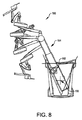
図8は、多くの実施形態による、ロボット手術システム160のための支持リンク機構の回転限度に関連付けられる重心図を示す。ロボット手術システム160の重心162を手術システム160の支持リンク機構164に対して一側に最大の範囲まで移動させるようにロボット手術システム160の構成要素が位置決めされるとともに配向される状態では、支持リンク機構164のショルダジョイントは、取付ベースの所定の安定限度を超えることを防ぐようにセットアップ構造(SUS)ショルダジョイント軸166周りの支持構造164の回転を制限するように構成されることができる。
FIG. 8 illustrates a centroid view associated with the rotational limits of the support link mechanism for the robotic surgery system 160, in accordance with many embodiments. With the components of the robotic surgical system 160 positioned and oriented to move the center of
図9は、操作のリモートセンタ(RC)を通る冗長軸及び付随する冗長な機械的な自由度の実装のための他のアプローチを示す。図9は、多くの実施形態による、リモートセンタマニピュレータ260を示し、このリモートセンタマニピュレータは、操作のリモートセンタ(RC)に対して一定の曲率半径を有する湾曲機構(curved feature)264を含む取付ベース262を含み、この湾曲機構に沿ってマニピュレータ260の中心線を外側寄り(outboard)(近位の)リンク機構のベースリンク266が再位置決めされることができる。外側寄りリンク機構はベースリンク266に取り付けられ、このベースリンク266は、操作のリモートセンタ(RC)と交差する第1の軸268周りの回転のための「ヨー」ジョイント機構を含む。ベースリンク266は、ベースリンク266が湾曲機構264に沿って選択的に再位置決めされるように拘束され、したがって、患者に対して固定位置で保持される取付ベース262に対して操作のリモートセンタ(RC)の位置を保持するように、湾曲機構264と連動され(interfaced with)る。湾曲機構264は、ベースリンク266の運動が操作のリモートセンタ(RC)と交差する第2の軸270周りの回転に制限されるように構成される。湾曲機構264に沿ってベースリンク266の位置を変化させることによって、患者に対するマニピュレータ260の外側寄りリンク機構の向きは変えられることができ、それによって、リモートセンタマニピュレータ260によって操作される手術器具の増大した運動範囲を提供する。平行四辺形機構272が、軸274周りの回転を提供する。平行四辺形機構全体が軸268周りに回転するとき、軸270及び軸274は一致させられることができることが分かる。
FIG. 9 illustrates another approach for the implementation of redundant axes and associated redundant mechanical degrees of freedom through the remote center of operation (RC). FIG. 9 illustrates a
図10は、操作のリモートセンタ(RC)を通る冗長軸の実装のための他のアプローチを示し、関連付けられる冗長自由度を提供する。図10は、多くの実施形態による、リモートセンタマニピュレータ280を示し、このリモートセンタマニピュレータは、内部でマニピュレータ280の外側寄り(遠位)リンク機構のベースリンク286が再位置決めされることができる、閉ループ湾曲機構284を含む取付ベース282を含む。図示されるように、中心取付要素285は閉ループ湾曲機構284の内部で回転する。ベースリンク286は、操作のリモートセンタに向かって少し内側へ向けられるように、中心取付要素285に取り付けられる。外側寄りリンク機構は、操作のリモートセンタ(RC)と交差する第1の軸288周りの回転のためにベースリンク286に取り付けられる。閉ループ湾曲機構284は、湾曲機構284の周りのベースリンク286の全ての位置に対して、操作のリモートセンタ(RC)の位置が、患者に対して固定されて保持される取付ベース282に対して固定されたままであるように、構成される。閉ループ湾曲機構284は、円形且つ操作のリモートセンタ(RC)と交差する第2の軸290周りに軸対称である。閉ループ湾曲機構284周りにベースリンク286の位置を変更することによって、患者に対するマニピュレータ280の外側寄りリンク機構の向きは変更されることができ、それによって、増大した運動範囲、アームとアーム又はアームと周囲の衝突回避、及び/又はリモートセンタマニピュレータ280のための運動学的な特異点回避を提供する。「部分円」機構又は取付ベースが円の一部を移動するのみである完全円形機構も使用されることができる。湾曲機構284及びその関連付けられる中心取付機構285は、円錐スイープジョイントとして機能することがわかる。
FIG. 10 shows another approach for the implementation of redundant axes through the remote center of operation (RC), providing the associated redundant degrees of freedom. FIG. 10 shows a remote center manipulator 280 according to many embodiments, which is a closed loop in which the base link 286 of the outboard (distal) link mechanism of the manipulator 280 can be repositioned It includes a mounting base 282 that includes a bending mechanism 284. As shown, the
図11は、器具ホルダ342が最大量までピッチバックされた(pitched back)リモートセンタマニピュレータ320の側面図である。図示された形態では、第1の平行四辺形リンク330は、延長リンク324と位置合わせされるところをちょうど過ぎた位置に回転されており、第2の平行四辺形リンク336は、第1の平行四辺形リンク330と位置合わせされるところをちょうど過ぎた位置に回転されており、それによって、挿入軸366をヨー軸348に対する垂線374から75度の角度オフセットに向ける。リモートセンタマニピュレータ320は、例えば、器具ホルダ342がヨー/ピッチハウジング346と接触しないように延長リンク324の長さを増加させることによって、さらに大きい最大ピッチバック角度を達成するように構成されることができるが、得られる追加的なピッチバック角度は、挿入軸366とヨー軸348との間の角度が15度未満に減少するとき、操作のリモートセンタ(RC)に対する器具ホルダ342のヨー運動に関するリモートセンタマニピュレータ320の運動学が、次第に不完全に条件付けられるようになることを考えれば、実用的な値にならないかもしれない。
FIG. 11 is a side view of
指令形成 Command formation
図12は、振動を減衰させるための指令形成のためのプロセス600の1つの実施形態を示すフローチャートである。プロセス600は、MIRSシステム10のようなロボットシステムの及び特に患者側カート22の運動を滑らかににするために使用されることができる。幾つかの実施形態では、プロセス600は、MIRSシステム10のようなロボットシステムがモードを変更するとき実行されることができ、幾つかの実施形態では、プロセス600は、ロボットシステムによるいかなるモード変更にかかわらず実行されることができる。プロセス600は、ロボットシステムの一部である及び/又はロボットシステムに接続されているプロセッサ及び/又は制御システムを使用して実行されることができる。幾つかの実施形態では、プロセス600は、例えば、プロセッサ58によって実行されることができる。
FIG. 12 is a flow chart illustrating one embodiment of a
プロセス600は、ブロック602で始まり、自由度(DOF)が特定される。幾つかの実施形態では、自由度は、MIRSシステム10の及び/又はMIRSシステム10の構成要素、ジョイント、又は機構の自由度(DOFs)の1つであることができる。幾つかの実施形態では、特定された自由度は、モード変更によって影響を受けるMIRSシステム10の部分に関連することができる。幾つかの実施形態では、これらの自由度に関連する情報が、MIRSシステム10に関連付けられるメモリに格納されることができ、このメモリは、例えば、プロセッサ58と接続されることができる。幾つかの実施形態では、自由度の1つ又は幾つかに関連する情報は、メモリから取得することができる、及び/又は生成若しくは収集されることができる。
自由度が、ブロック602で特定された後、プロセス600は、ブロック606に進み、モードデータが取得される。幾つかの実施形態では、モードデータは、MIRSシステム10の動作の1つ又は幾つかのモードを特定することができる。1つの実施形態では、例えば、このモードデータは、MIRSシステム10の動作の現在のモード、MIRSシステム10の動作の1若しくは幾つかの過去のモード、及び/又はMIRSシステム10の動作の将来若しくは要求されたモードを特定することができる。幾つかの実施形態では、動作の現在のモードと異なる動作の要求されたモードの特定は、モード移行をもたらすことができ、このモード移行は、幾つかの実施形態において、本明細書に開示された指令形成なしに、著しい振動を発生させ得る。幾つかの実施形態では、モードデータは、メモリ、外科医用コンソール16、及び/又は電子装置カート24から受信されることができる。
After the degrees of freedom are identified at
モードデータが受信された後、プロセス600は、決定状態608に進み、モード移行が生じたか及び/又は生じているかどうかが決定される。モード移行が生じたか及び/又は生じているかどうかの決定は、MIRSシステム10の動作に関連する情報をモード移行が生じたか及び/又は生じているかどうかを決定するための基準と比較することを含むことができる。幾つかの実施形態では、これらの基準は、モード移行に関連付けられようがなかろうが、振動を発生させる及び/又は発生させる可能性がある任意の動作、が要求されたかどうか、並びに/又はこれらの振動がある閾値より大きい、小さい、又は等しいかどうかを決定することを含むことができる。幾つかの実施形態では、要求された動作が閾値より大きいMIRSシステム10の1又は幾つかの構成要素の加速を通じて達成されるとき、要求された動作が振動を発生させる及び/又は振動を発生させる可能性がある。幾つかの実施形態では、閾値は、例えば、加速度を生じさせる力の源、力及び/又は加速度を受けるMIRSシステム10の部分の剛性の程度等を含む、多くの要因に基づいて変わることができる。幾つかの実施形態では、この決定はさらに、例えば、要求されたモード移行を含む、要求された動作が、MIRSシステム10の一部を静的から動的に、又は動的から静的に変換するかどうかを決定することを含むことができる。これらの決定は、プロセッサ58及び/又はMIRSシステム10の他の構成要素によってなされることができる。
After mode data is received,
幾つかの実施形態では、モード移行が生じたかどうかの決定はさらに、平滑化及び/又は指令形成が要求されているかどうかを決定することを含むことができる。幾つかの実施形態では、この決定は、外科医及び/又はMIRSシステム10の他のユーザから受信される1又は幾つかの入力に基づいてなされることができる。1つの実施形態では、この情報は、メモリ内に格納されることができ、プロセス600が例えばプロセッサ58によって実行されるとき取り出されることができる。
In some embodiments, determining whether mode transition has occurred may further include determining whether smoothing and / or command formation is required. In some embodiments, this determination can be made based on one or several inputs received from the surgeon and / or other users of the MIRS system 10. In one embodiment, this information may be stored in memory and retrieved when
モード移行が生じた及び/又は生じているかどうかが決定された後、プロセス600は、ブロック610に進み、位置パラメータが取り出される。幾つかの実施形態では、位置パラメータは、MIRSシステム10の1又は幾つかの構成要素の位置を規定及び/又は特定することができる。幾つかの実施形態では、位置パラメータは、例えば、固定座標系に対してのように、絶対的に、及び/又はMIRSシステム10の1又は幾つかの他の構成要素に対して相対的に、MIRSシステム10の1又は幾つかの構成要素の位置を規定することができる及び/又は特定することができる。幾つかの実施形態では、位置パラメータは、MIRSシステム10によって取り出されることができる及び/又は決定されることができる。
After it is determined if mode transition has occurred and / or has occurred, the
位置パラメータが取り出された後、プロセス600は、ブロック612に進み、速度パラメータが取り出される。幾つかの実施形態では、速度パラメータは、MIRSシステム10の1又は幾つかの構成要素の速度を規定及び/又は特定することができる。幾つかの実施形態では、速度パラメータは、例えば、固定座標系に対してのように、絶対的に、及び/又はMIRSシステム10の1又は幾つかの他の構成要素に対して相対的に、MIRSシステム10の1又は幾つかの構成要素の速度を規定することができる及び/又は特定することができる。幾つかの実施形態では、速度パラメータは、MIRSシステム10によって取り出されることができる及び/又は決定されることができる。
After the position parameters are retrieved,
速度パラメータが取り出された後、プロセス600は、ブロック614に進み、加速度パラメータが取り出される。幾つかの実施形態では、加速度パラメータは、MIRSシステム10の1又は幾つかの構成要素の加速度を規定及び/又は特定することができる。幾つかの実施形態では、加速度パラメータは、例えば、固定座標系に対してのように、絶対的に、及び/又はMIRSシステム10の1又は幾つかの他の構成要素に対して相対的に、MIRSシステム10の1又は幾つかの構成要素の加速度を規定することができる及び/又は特定することができる。幾つかの実施形態では、加速度パラメータは、MIRSシステム10によって取り出されることができる及び/又は決定されることができる。
After the velocity parameters are retrieved,
加速度パラメータが取り出された後、プロセス600は、ブロック616に進み、平滑化曲線が計算される。平滑化曲線は、反復計算される複数のステップで作られることができる。幾つかの実施形態では、平滑化曲線は、MIRSシステム10及び/又はそれの構成要素の現在の位置、速度、及び/又は加速度と、要求された動作及び/又はモード移行によって特定される位置、速度及び/又は加速度との間の移行経路を規定することができる。幾つかの実施形態では、移行経路は、振動を最小化及び/又は除去する経路であることができる。1つの実施形態では、移行経路は、要求された動作及び/又はモード移行によって影響を受けるMIRSシステム10及び/又はそれの構成要素の位置、速度、加速度、ジャーク、及び/又は他のパラメータにおける不連続のような不連続がないことができる。1つの実施形態では、速度における不連続を有さない移行経路が、C1連続であり、加速度における不連続を有さない移行経路が、C2連続であり、ジャークにおける不連続を有さない移行経路が、C3連続である。幾つかの実施形態では、平滑化曲線の計算は、MIRSシステム10及び/又はそれの構成要素の1又は幾つかの次の位置、速度、加速度、ジャーク、及び/又は他のパラメータを含むことができる。幾つかの実施形態では、MIRSシステム10及び/又はそれの構成要素のこれらの1又は幾つかの次の位置、速度、加速度、ジャーク、及び/又は他のパラメータは、トリガ閾値が達成されるまで、及び/又はプロセス600の再開をトリガする他の動作が要求されるまで、いつまでも計算されることができる。平滑化曲線は、プロセッサ58又はMIRSシステム10の他の構成要素によって計算されることができる。平滑化曲線の計算の詳細は、いかにより大きい長さで論じられる。
After the acceleration parameters are retrieved,
平滑化曲線が計算された後、プロセス600は、ブロック618に進み、平滑化曲線が適用される。上で論じられたように、幾つかの実施形態では、平滑化曲線は、MIRSシステム10及び/又はそれの構成要素の1又は幾つかの次の位置、速度、加速度、ジャーク、及び/又は他のパラメータを含むことができる。幾つかの実施形態では、平滑化曲線は、例えば、MIRSシステム10及び/又はそれの構成要素を操作する1又は幾つかのモータを含む、MIRSシステム10及び/又はそれの構成要素に適用されることができる。平滑化曲線の適用は、プロセッサ58又はMIRSシステム10の他の構成要素によって制御されることができる。
After the smoothing curve is calculated,
平滑化曲線が適用された後、プロセス600は、決定状態620に進み、追加の平滑化が必要か及び/又は望まれているかどうかが決定される。幾つかの実施形態では、これは、例えば、MIRSシステム10及び/又はそれの構成要素の1又は幾つかのパラメータをいつ平滑化が終了されることができるか及び/又は終了されるべきかを特定する閾値と比較することによって平滑化プロセスを終了させるかどうかを決定することを含むことができる。幾つかの実施形態では、追加の平滑化を提供するかどうかの決定は、例えば、追加のモード移行を含み得る追加の動作が要求されているかどうかを決定することを含むことができる。この決定は、例えば、プロセッサ58によってなされることができる。追加の平滑化が必要とされることが決定される場合、プロセス600は、ブロック610に戻り、上で概説されたように進む。
After the smoothing curve is applied,
プロセス600は、MIRSシステム10の自由度に関する並列/同時処理又は順次処理を含むことができる。自由度が並列/同時に処理される幾つかの実施形態では、図12に描かれた決定状態622は省略されてもよい。再びプロセス600に戻ると、追加の平滑化が必要とされていないことが決定される場合、プロセスは、決定状態622に進み、MIRSシステム10に関連付けられる追加の自由度があるかどうかが決定される。追加の、まだ特定されていない自由度があることが決定される場合、プロセス600は、ブロック602に戻り、上で概説されたように進む。MIRSシステム10に関連付けられる追加の及び/又は特定された自由度がないことが決定される場合、プロセスは、幾つかの実施形態において、終了することができる。
図13は、平滑化曲線を計算するためのプロセス640の1つの実施形態を示すフローチャートである。幾つかの実施形態では、プロセス640は、図12に示されるブロック616の場所で実行されることができる。図12のプロセス600のように、プロセス640は、MIRSシステム10及び/又はそれの構成要素によって実行されることができる。
FIG. 13 is a flow chart illustrating one embodiment of a
プロセス640は、ブロック642で始まり、指令位置が確立される。幾つかの実施形態では、指令位置は、要求された動作にさらされるMIRSシステム10及び/又はそれの構成要素の現在位置であることができる。指令位置が確立された後、プロセス640は、決定状態644に進み、要求された動作が新しい動作であるかどうかが決定される。幾つかの実施形態では、この決定は、平滑化が、要求された動作に対して既に生じたか及び/又は要求された動作に対して既に開始されたかどうかを決定することを含むことができる。平滑化が、既に生じている及び/又は既に開始されている場合、プロセス640は、ブロック646に進み、システムは初期化される。幾つかの実施形態では、システムの初期化は、平滑化曲線の生成のための1又は幾つかの初期パラメータを確立することを含むことができる。幾つかの実施形態では、これは、1又は幾つかの減衰係数、位置、速度、又は同様のものを特定するパラメータを確立することを含むことができる。
システムが、初期化された後、プロセス640は、ブロック648に進み、ステップ値が計算される。幾つかの実施形態では、ステップ値は、要求された動作によって影響を受ける、シミュレートされた減衰システム、MIRSシステム10及び/又はそれの構成要素の位置及び/又は速度の1又は幾つかの次のパラメータを規定する値であることができる。このようなシミュレートされた減衰システムの詳細は、以下にさらなる長さで論じられる。
After the system has been initialized,
幾つかの実施形態では、ステップ値は、指令位置からステップ値によって特定される方法でステップ値によって特定される位置に動くとき、MIRSシステム10及び/又はそれの構成要素がジャークを受けないように計算されることができる。ステップ値は、プロセッサ58を使用して計算されることができる。どのようにステップ値が計算されることができるかの詳細は、以下にさらなる長さで論じられる。 In some embodiments, as the step value moves from the commanded position to the position specified by the step value in the manner specified by the step value, the MIRS system 10 and / or its components are not subject to jerks It can be calculated. Step values may be calculated using processor 58. The details of how step values can be calculated are discussed in further lengths below.
ステップ値が計算された後、プロセス640は、ブロック650に進み、新しい指令位置が設定される。幾つかの実施形態では、新しい指令位置は、計算されたステップ値、計算されたステップ値の1つ、又は最初に確立された指令位置と計算されたステップ値の組み合わせに設定されることができる。指令位置は、MIRSシステム10に関連付けられるメモリに格納されることができる。指令位置が設定された後、プロセス640は、ブロック652に進み、図12のブロック618に続く。
After the step value is calculated,
図14A及び14Bは、平滑化曲線を計算するために使用される機械的システム(機械系)及び/又はシミュレートされた減衰システム(減衰系)700の1つの実施形態の説明図である。図14Aでは、シミュレートされた減衰システム700が、可動部分があるとして描かれ、図14Bでは、運動の全てが停止した及び/又は事実上停止した後のシミュレートされた減衰システム700が描かれている。同じシミュレートされた減衰システム700は、運動を停止させる及び/又は運動を遅くさせるために平滑化曲線を決定するために使用されることができ、幾つかの実施形態では、シミュレートされた減衰システム700は、運動を開始させる及び/又は加速させるために平滑化曲線を決定するために使用されることができる。
14A and 14B are illustrations of one embodiment of a mechanical system (mechanical system) and / or a simulated damping system (damping system) 700 used to calculate the smoothing curve. In FIG. 14A, the simulated damping
シミュレートされた減衰システム700は、システム質量702を含む。システム質量702は、MIRSシステム10及び/又は要求された動作によって影響を受けるMIRSシステム10の構成要素の質量を表す。システム質量702の値は、MIRSシステム10に関連付けられるメモリに格納されることができる、及び/又は、例えば、1又は幾つかのモータのような、MIRSシステム10の構成要素から受信されるフィードバックに基づいて生成されることができる。幾つかの実施形態では、システム質量は、システム質量は、所望の加速度を達成するために必要とされる力の量に基づいて決定されることができる。
The
図14A及び14Bに描かれたように、システム質量は、システム質量702のシミュレートされた減衰システム700の構成要素との相互作用に応じて時間にわたって変化するvs(t)として示される速度を有する。シミュレートされた減衰システム700は、第1のダッシュポット708を介して第2の質量706と、及び第2のダッシュポット712を介して地面710と相互作用する第1の質量704を含む。幾つかの実施形態では、第1及び第2の質量704、706は、第1及び第2の質量704、706の質量と特定する任意の所望の値を有することができる。幾つかの実施形態では、第1の質量704の質量は、第2の質量の質量と同じであることができ、幾つかの実施形態では、第1の質量704の質量は、第2の質量706の質量と異なることができる。幾つかの実施形態では、第1及び第2の質量704、706の質量は、第1及び第2のダッシュポット708、712と組み合わされて、シミュレートされた減衰システム700が、システム質量702のパラメータに関してC1、C2、C3、C4、C5、及び/又はC6連続平滑化曲線を作ることができるように選択されることができる。幾つかの実施形態では、様々な第1及び第2の質量704、706の質量が、システム質量702のパラメータに関してC1、C2、C3、C4、C5、及び/又はC6連続平滑化曲線の作成をもたらすことができる。
As depicted in FIGS. 14A and 14B, the system mass has a velocity shown as vs (t) that changes over time in response to the interaction of
同様に、第1のダッシュポット708及び第2のダッシュポット712は、それぞれ、例えば、減衰係数によって記載されることができる。幾つかの実施形態では、第1のダッシュポット708の減衰係数は、第2のダッシュポット712の減衰係数と同じであることができ、幾つかの実施形態では、第1のダッシュポット708の減衰係数は、第2のダッシュポット712の減衰係数と異なることができる。
Similarly, the
幾つかの実施形態では、ダッシュポット708、712の減衰係数は、動作が要求されるときの時間と要求された動作によって影響を受けるMIRSシステム10及び/又はMIRSシステム10の構成要素が要求された動作を完了する及び/又は要求された動作を事実上完了するときの時間との間の要求された動作によって影響を受けるMIRSシステム10及び/又はMIRSシステム10の構成要素が経験する総移動距離を軽減する及び/又は除去するように構成されることができる。幾つかの実施形態では、要求された動作は、要求された動作によって影響を受けるMIRSシステム10及び/又はMIRSシステム10の構成要素が、要求された動作の位置、速度、及び/又は加速度に漸近的に近づくとき、事実上完了する。
In some embodiments, the damping factor of
幾つかの実施形態では、ダッシュポット708、712の減衰係数は、要求された動作の実行によって生じる振動を緩和する及び/又は除去するように構成されることができる。幾つかの実施形態では、ダッシュポット708、712の減衰係数の値は、MIRSシステム10を制御する外科医の能力に最小に作用する及び/又はMIRSシステム10によって実行される動作の結果に最小に悪影響を及ぼす結果を提供するように、最適化されることができる。幾つかの実施形態では、第1及び第2の質量704、706の特定の質量、並びにダッシュポット708、712の減衰係数は、シミュレートされた減衰システム700の所望の性能及び/又は応答並びに/又は平滑化曲線の形状及び/又は軌道を最適化するように同時に選択されることができる。
In some embodiments, the damping factor of
図15は、指令形成アルゴリズムを初期化するためのプロセス660の1つの実施形態を示すフローチャートである。プロセス660は、図13のブロック646の一部として、又は図13のブロック646に代わって実行されることができる。プロセスはブロック662で始まり、第1の質量の位置が、図13のブロック642で確立された指令位置と等しいように指定される。第1の質量704の位置が指令位置と等しく設定された後、第1の質量704の速度が指令速度と等しく、言い換えると、動作が要求される直前のシステム質量702の速度vs(t)と等しく、設定されるときプロセス660はブロック664に進む。
FIG. 15 is a flow chart illustrating one embodiment of a
第1の質量704の速度が指令速度と等しく設定された後、プロセス660はブロック666に進み、第2の質量706の位置が第1の質量704の位置と等しく設定され、したがって、図13のブロック642で確立された指令位置と等しいように設定される。第2の質量706の位置が指令位置と等しく設定された後、プロセス660はブロック668に進み、第2の質量706の速度は、第1の質量704の速度と等しく設定される、又は言い換えると、指令速度と等しく設定され、この指令速度は、動作が要求される直前のシステム質量702の速度vs(t)である。第2の質量706の速度が第1の質量704の速度に設定された後、プロセス660はブロック670に進み、図13のブロック648に続く。
After the velocity of the
図16は、ステップ値を計算するためのプロセスの1つの実施形態を示すフローチャートである。プロセス680は、ブロック682で始まり、第1の質量704の次の位置が計算される。幾つかの実施形態では、第1の質量704の位置は、以下の式にしたがって計算されることができ、ここでx1は第1の質量704の初期位置であり、v1は第1の質量の初期速度であり、Tは、例えば、サーボ時間ステップの持続期間のような時間の期間であり、x1’は第1の質量704の次の位置である。
FIG. 16 is a flow chart illustrating one embodiment of a process for calculating step values.
x1’=v1*T+x1 x1 '= v1 * T + x1
第1の質量704の次の位置が計算された後、プロセス680は、ブロック684に進み、第1の質量704の次の速度が計算される。幾つかの実施形態では、第1の質量704の次の速度は、以下の式にしたがって計算されることができ、ここでv1は、第1の質量704の初期速度であり、v2は、第2の質量706の初期速度であり、b1は、第1のダッシュポット708の減衰係数であり、b2は、第2のダッシュポット712の減衰係数であり、v1’は、第1の質量704の次の速度である。
After the next position of the
v1’=v1−b1*v1−b2*v1+b2*v2 v1 '= v1-b1 * v1-b2 * v1 + b2 * v2
第1の質量704の次の速度が計算された後、プロセス680は、ブロック686に進む、第2の質量706の次の位置が計算される。幾つかの実施形態では、第2の質量706の次の位置は、以下の式にしたがって計算されることができ、ここでx2は第2の質量706の初期位置であり、v2は第2の質量706の初期速度であり、Tは、例えば、サーボ時間ステップの持続期間のような時間の期間であり、x2’は第2の質量706の次の位置である。
After the next velocity of the
x2’=v2*T+x2 x2 '= v2 * T + x2
第2の質量706の次の位置が計算された後、プロセス680は、ブロック688に進み、第2の質量706の次の速度が計算される。幾つかの実施形態では、第2の質量706の次の速度は、以下の式にしたがって計算されることができ、ここでv1は、第1の質量704の初期速度であり、v2は、第2の質量706の初期速度であり、b1は、第1のダッシュポット708の減衰係数であり、b2は、第2のダッシュポット712の減衰係数であり、v2’は、第2の質量706の次の速度である。
After the next position of
v2’=v2+b2*v1+b2*v2 v2 '= v2 + b2 * v1 + b2 * v2
幾つかの実施形態では、ステップ682−688は、プロセッサ58又はMIRSシステム10の他の構成要素によって実行されることができる。第2の質量706の速度が計算された後、プロセス680はブロック690に進み、図13に示されたブロック650に続く。
In some embodiments, steps 682-688 may be performed by processor 58 or other components of MIRS system 10. After the velocity of the
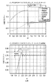
図17A及び17Bは、振動を減衰させるための指令形成が使用されるときの結果の振動を減衰させるための指令形成が使用されないときの結果との比較を示す。図17Aのプロットは、本明細書に記載される平滑化なしで生じるような急なモード移行を描き、図17Bのプロットは、本明細書に記載される平滑化を伴って生じるような滑らかなモード移行を描いている。 17A and 17B show a comparison with the results when command formation for damping vibrations is not used when the command formation for damping vibrations is used. The plot of FIG. 17A depicts a sharp mode transition as occurs without the smoothing described herein, and the plot of FIG. 17B is smooth as occurring with the smoothing described herein. The mode transition is drawn.
図17Aを参照すると、「ピッチDOFのテイクオフ(takeoff)とランディング(landing)、ケース:5(サーボ)」と題したプロットにおいて、MIRSシステム10の内部で測定されたデータが描かれている。プロットは、時間に応じた指令位置を特定する「Cmdpos」と標識されたトレース、時間に応じたMIRSシステム10の一部の実際の位置を特定する「Actpos」と標識されたトレース、MIRSシステム10の一部のモード移行の瞬間及び所望の最終位置を特定する「Lockpos」と標識されたトレース、時間に応じた指令速度を特定する「Cmdvel」と標識されたトレース、時間に応じたMIRSシステム10の一部の実際の速度を特定する「Actvel」と標識されたトレース、時間に応じたトレースCmdposとActposとの間の差を特定する「Err」と標識されたトレース、及び時間に応じたMIRSシステム10の1又は幾つかのモータによって加えられるトルクの微分を特定する「Torque Diff」と標識されたトレースを含む。トレースの全ては、同じスケールを有して描かれているが、トレースErrは、MIRSシステム10の一部の実際の位置における振動を明確に示すために拡大されているので、他のものと同じスケールと有していない。 Referring to FIG. 17A, the data measured inside the MIRS system 10 is depicted in a plot entitled "Takeoff and landing for pitch DOF, Case: 5 (servo)". The plot is a trace labeled "Cmdpos" identifying the commanded position according to time, a trace labeled "Actpos" identifying the actual position of a portion of MIRS system 10 depending on time, MIRS system 10 A trace labeled "Lockpos" that identifies the moment of mode transition and a desired final position of a part, a trace labeled "Cmdvel" that identifies a commanded velocity according to time, MIRS system 10 depending on time 10 Traces labeled "Actvel" identifying the actual velocity of a portion of the trace, traces labeled "Err" identifying the difference between the traces Cmdpos and Actpos as a function of time, and MIRS as a function of time Identify the derivative of the torque applied by one or several motors of the system 10 “Torque Contains a trace labeled "Diff". All of the traces are drawn with the same scale, but the trace Err is the same as others, as it is scaled to clearly show the oscillations in the actual position of a part of the MIRS system 10 Not with the scale.
「ピッチDOFのテイクオフとランディング、ケース:5(極座標(Polaris))」と標識されたプロットにおいて、MIRSシステム10の外部で測定されたデータが描かれている。具体的には、「ピッチDOFのテイクオフとランディング、ケース:5(極座標)」と標識されたプロットに描かれたデータは、外部測定装置を用いて生成された。「ピッチDOFのテイクオフとランディング、ケース:5(極座標)」と標識されたプロットのデータは、時間に応じたMIRSシステム10の一部の実際の位置を描いている。「ピッチDOFのテイクオフとランディング、ケース:5(極座標)」と標識されたプロットのこのデータは、「ピッチDOFのテイクオフとランディング、ケース:5(サーボ)」と標識されたプロットのトレースActposに対応している。 Data measured outside of MIRS system 10 are depicted in a plot labeled "Takeoff and Landing of Pitch DOF, Case: 5 (Polaris)". Specifically, the data depicted in the plot labeled "Takeoff and Landing of Pitch DOF, Case: 5 (Polar Coordinates)" was generated using an external measurement device. The plot data labeled "Pitch DOF Takeoff and Landing, Case: 5 (Polar Coordinates)" depicts the actual position of a portion of the MIRS system 10 as a function of time. This data of the plot labeled "Takeoff and landing for pitch DOF, case: 5 (polar coordinates)" corresponds to the trace Actpos of the plot labeled "takeoff and landing for pitch DOF, case: 5 (servo)" doing.
図17Aに示されるように、振動が、t=1で発生するモード移行に起因して生じる。これらの振動は、MIRSシステム10の一部の実際の位置及び速度に関連するトレースの全てにおいて明白である。図17Aに見られるように、本明細書に概説されたような指令形成を使用しなかったことは、オーバーシュート及び振動をもたらし得る。特定の描かれた実施形態では、本明細書に概説されたような指令形成を使用しなかったことは、1.04ラジアン/秒の初期速度を有する構成要素に関して約10mmのオーバーシュートをもたらした。このオーバーシュートは、所望の停止ポイント(0.75ラジアンに位置する)と所望の停止ポイントを超えた最大変位との間の距離として測定されている。 As shown in FIG. 17A, vibration occurs due to the mode transition that occurs at t = 1. These oscillations are evident in all of the traces associated with the actual position and velocity of a portion of the MIRS system 10. As seen in FIG. 17A, not using command formation as outlined herein can result in overshoot and vibration. In certain depicted embodiments, not using command formation as outlined herein resulted in an overshoot of about 10 mm for components having an initial velocity of 1.04 rad / s. . This overshoot is measured as the distance between the desired stopping point (located at 0.75 radian) and the maximum displacement beyond the desired stopping point.
図17Bを参照すると、「ピッチDOFのテイクオフとランディング、ケース:15(サーボ)」と題したプロットにおいて、MIRSシステム10の内部で測定されたデータが描かれている。プロットは、時間に応じた指令位置を特定する「Cmdpos」と標識されたトレース、時間に応じたMIRSシステム10の一部の実際の位置を特定する「Actpos」と標識されたトレース、MIRSシステム10の一部のモード移行の瞬間及び所望の最終位置を特定する「Lockpos」と標識されたトレース、時間に応じた指令速度を特定する「Cmdvel」と標識されたトレース、時間に応じたMIRSシステム10の一部の実際の速度を特定する「Actvel」と標識されたトレース、時間に応じたトレースCmdposとActposとの間の差を特定する「Err」と標識されたトレース、及び時間に応じたMIRSシステム10の1又は幾つかのモータによって加えられるトルクの微分を特定する「Torque Diff」と標識されたトレースを含む。トレースの全ては、同じスケールを有して描かれているが、トレースErrは、MIRSシステム10の一部の実際の位置における振動を明確に示すために拡大されているので、他のものと同じスケールと有していない。 Referring to FIG. 17B, the data measured inside the MIRS system 10 is depicted in a plot entitled "Takeoff and Landing of Pitch DOF, Case: 15 (Servo)". The plot is a trace labeled "Cmdpos" identifying the commanded position according to time, a trace labeled "Actpos" identifying the actual position of a portion of MIRS system 10 depending on time, MIRS system 10 A trace labeled "Lockpos" that identifies the moment of mode transition and a desired final position of a part, a trace labeled "Cmdvel" that identifies a commanded velocity according to time, MIRS system 10 depending on time 10 Traces labeled "Actvel" identifying the actual velocity of a portion of the trace, traces labeled "Err" identifying the difference between the traces Cmdpos and Actpos as a function of time, and MIRS as a function of time Identify the derivative of the torque applied by one or several motors of the system 10 “Torque Contains a trace labeled "Diff". All of the traces are drawn with the same scale, but the trace Err is the same as others, as it is scaled to clearly show the oscillations in the actual position of a part of the MIRS system 10 Not with the scale.
「ピッチDOFのテイクオフとランディング、ケース:15(極座標)」と標識されたプロットにおいて、MIRSシステム10の外部で測定されたデータが描かれている。具体的には、「ピッチDOFのテイクオフとランディング、ケース:15(極座標)」と標識されたプロットに描かれたデータは、外部測定装置を用いて生成された。「ピッチDOFのテイクオフとランディング、ケース:15(極座標)」と標識されたプロットのデータは、時間に応じたMIRSシステム10の一部の実際の位置を描いている。「ピッチDOFのテイクオフとランディング、ケース:15(極座標)」と標識されたプロットのこのデータは、「ピッチDOFのテイクオフとランディング、ケース:15(サーボ)」と標識されたプロットのトレースActposに対応している。 Data measured outside of MIRS system 10 are depicted in a plot labeled "Takeoff and Landing of Pitch DOF, Case: 15 (Polar Coordinates)". Specifically, the data depicted in the plot labeled "Takeoff and Landing of Pitch DOF, Case: 15 (Polar Coordinates)" was generated using an external measurement device. The plot data labeled "Pitch DOF Takeoff and Landing, Case: 15 (Polar Coordinates)" depicts the actual position of a portion of the MIRS system 10 as a function of time. This data of the plot labeled "Takeoff and landing for pitch DOF, case: 15 (polar coordinates)" corresponds to the trace Actpos of the plot labeled "takeoff and landing for pitch DOF, case: 15 (servo)" doing.
図17Bに示されるように、本明細書に概説されたような指令形成の使用は、図17Aに示されるような振動を除去した。具体的には、「ピッチDOFのテイクオフとランディング、ケース:15(極座標)」と標識されたプロットに見られるように、位置は、安定した値に滑らかに近づいている。この実施形態では、本明細書に記載されたような指令形成の使用は、C3連続であり、したがって、ジャークに不連続を有さない平滑化曲線を作った。「ピッチDOFのテイクオフとランディング、ケース:15(極座標)」と標識されたプロットにさらに見られるように、本明細書に概説されたような指令形成の使用は、オーバーシュートを除去するが、ドリフト、具体的には、描かれた実施形態において、1.04ラジアン/秒の初期速度を有する構成要素に関して約35mmのドリフトをもたらす。このドリフトは、所望の停止ポイント(0.75ラジアンに位置する)と所望の停止ポイントを超えた最大変位との間の距離として測定されている。しかし、驚くべきことに、本明細書の指令形成の使用は、本明細書に記載される指令形成が使用されないときに作られたオーバーシュートより著しく大きいが、本明細書に記載される指令形成の使用は、より良い臨床結果を提供し、ユーザにMIRSシステム10の制御のより良い感覚を提供する。 As shown in FIG. 17B, the use of command formation as outlined herein eliminated the vibrations as shown in FIG. 17A. Specifically, as seen in the plot labeled "Takeoff and Landing of Pitch DOF, Case: 15 (Polar Coordinates)", the position is smoothly approaching a steady value. In this embodiment, the use of command formation as described herein is C3 continuous, thus creating a smoothing curve with no discontinuities in the jerk. As further seen in the plot labeled "Takeoff and Landing of Pitch DOF, Case: 15 (Polar Coordinates)", the use of command formation as outlined herein eliminates the overshoot but drifts In particular, in the depicted embodiment, this results in a drift of about 35 mm for components having an initial velocity of 1.04 rad / s. This drift is measured as the distance between the desired stopping point (located at 0.75 radians) and the maximum displacement beyond the desired stopping point. However, surprisingly, the use of the directive formation herein is significantly greater than the overshoot created when the directive formation described herein is not used, but the directive formation described herein The use of provides better clinical results and provides the user with a better feeling of control of the MIRS system 10.
さらに、幾つかの実施形態では、第1及び第2のダッシュポット708、712に関する減衰係数は、異なる結果を作るために操作されることができる。したがって、1つの実施形態では、ある減衰係数は、かなりのオーバーシュート及び最小のドリフトをもたらし得るとともに、他の実施形態では、ある減衰係数は、最小のオーバーシュート及びかなりのドリフトを引き起こすことができる。有利には、ある減衰係数の組み合わせは、所望の臨床及び/又は制御結果を生じさせることができる。同様に、幾つかの実施形態では、ドリフト対オーバーシュートの比が約1.5:1、2.5:1、3:1、3.5:1、4:1、5:1、又は任意の他の中間の比であるとき、臨床結果及び外科医の体験(surgeon experience)が最大化されることが見出されている。1つの実施形態では、これらの比は、例えば、b1=3の第1のダッシュポット708に関する減衰係数によって及びb2=1の第2のダッシュポット712に関する減衰係数によって達成されることができる。
Further, in some embodiments, the attenuation factors for the first and
他の変形形態は本発明の精神の中にある。したがって、本発明は、様々な変更形態及び代替構造が可能であるが、幾つかの説明された実施形態は図面に示されるとともに詳細に記載されている。しかし、本発明を開示された特定の形態又は複数の形態に限定する意図はなく、それどころか、全ての修正、代替構造、及び添付の特許請求の範囲に定められるように、本発明の精神及び範囲内に属する均等物をカバーすることを意図していることが理解されるべきである。 Other variations are within the spirit of the invention. Thus, while the invention is susceptible to various modifications and alternative constructions, some described embodiments have been shown in the drawings and are described in detail. However, there is no intention to limit the invention to the particular form or forms disclosed, but rather the spirit and scope of the invention, as defined in all modifications, alternative constructions, and the appended claims. It should be understood that it is intended to cover the equivalents within.
本発明を記載する文脈における(特に以下の請求項の範囲の文脈における)用語“a”、“an”、“the”(1つの、ある)、及び同様の指示対象の使用は、本願にそうでないことが示されない限り又は文脈によって明らかに否定されない限り、単数形及び複数形の両方を包含するように解釈されるべきである。用語「有する、含む、備える(“comprising”、“having”、“including”、及び“containing”)」は、そうでないことが記載されない限りオープンエンドタームとして(すなわち、「含んでいるが限定されない」ことを意味する)解釈されるべきである。用語「接続される」は、たとえ何かが介在していても、部分的に又は完全に中に含まれる、取り付けられる、又は一緒に結合されるとして解釈されるべきである。本願における値の範囲の列挙は、本願にそうでないことが明記されない限り、範囲に入るそれぞれの独立した値を個別に参照する省略表現方法として機能することが単に意図され、それぞれの独立した値は、それが本願に個別に参照されるように、明細書に組み込まれる。本願に記載された全ての方法は、本願に明記されない限り又は文脈によって明らかに否定されない限り、任意の適切な順番で実行され得る。任意の及び全ての例、又は本願に用いられる例示的な言語(例えば、「等」)の使用は、本発明の実施形態をより良く明らかにすることを単に意図し、特許請求の範囲に記載されない限り、本発明の範囲の限定をもたらさない。明細書の言語は、本発明の実施に必須であるような任意の請求項に記載されていない要素を示すものとして解釈されるべきではない。 The use of the terms "a", "an", "the", and the like in the context of describing the invention (in particular in the context of the scope of the following claims) is hereby incorporated by reference. Unless otherwise indicated or unless explicitly denied by context, it should be construed to include both singular and plural forms. The terms "having, including, including" ("comprising", "having", "including" and "containing") are open-ended terms unless stated otherwise (i.e. "including, but not limited to") Mean that) should be interpreted. The term "connected" should be interpreted as partially attached or completely contained within, attached or coupled together, even though something is intervening. The recitation of ranges of values in the present application is merely intended to serve as a shorthand method of referring individually to each independent value falling within the range, unless it is expressly stated otherwise in the present application that each independent value is , Which is incorporated in the specification as it is individually referred to in the present application. All methods described herein may be practiced in any suitable order, unless expressly stated in the present application or specifically denied by context. The use of any and all examples, or exemplary languages (e.g., "etc") as used herein is merely intended to better illustrate the embodiments of the present invention and is described in the claims. Unless it does, it does not lead to a limitation of the scope of the present invention. The language of the specification should not be construed as indicating any non-claimed element as essential to the practice of the invention.
本発明を実施するために発明者に知られているベストモードを含む、本発明の好適な実施形態がここに記載されている。これらの好適な実施形態の変形形態は、前述の記載を読むことで当業者に明らかになり得る。発明者は、熟練した職人がこのような変形形態を適切に用いることを予期し、発明者は発明が、本願に具体的に記載されるものとは違う他の方法で実施されることを意図する。したがって、本発明は、全ての修正形態及び適用される法律によって許されるように添付された特許請求の範囲に記載された主題の均等物を含む。さらに、それらの全ての可能な変形形態の上述の構成要素の任意の組み合わせが、本願に明記されない限り又は文脈によって明らかに否定されない限り、本発明によって包含される。 Preferred embodiments of the invention are described herein, including the best mode known to the inventors for carrying out the invention. Variations of these preferred embodiments may become apparent to those skilled in the art upon reading the foregoing description. The inventor anticipates skilled artisans to properly use such variations, and the inventor intends that the invention be practiced in other ways than those specifically described in the present application. Do. Accordingly, this invention includes all modifications and equivalents of the subject matter recited in the claims appended hereto as permitted by applicable law. Furthermore, any combination of the above-described components of all possible variations thereof is encompassed by the present invention, unless explicitly stated otherwise in the present application or clearly excluded by context.
本願に引用された、出版物、特許出願、特許を含む全ての参考文献は、各参考文献が参照により組み込まれることが個々に且つ明確に示されるような、並びに且つ完全に本願に述べられているような、同じ程度まで、参照により本願に組み込まれる。
All references cited in this application, including publications, patent applications, and patents, are individually and clearly indicated that each reference is incorporated by reference, and are fully described in the present application. To the same extent, as incorporated herein by reference.
Claims (14)
プロセッサが、要求動作を受信するステップであって、前記要求動作は、前記ロボットシステムの患者側カートの一部の速度又は位置の変化を含む、ステップ;
前記プロセッサが、平滑化曲線を計算するステップであって、前記平滑化曲線は、前記患者側カートの前記一部と相互作用する減衰システムをシミュレートするシミュレートされた減衰システムにしたがって計算され、前記シミュレートされた減衰システムは、前記患者側カートの前記一部の質量を表すシステム質量と、前記システム質量と相互作用するとともに第1のダッシュポットを介して第2の質量に接続された第1の質量と、前記第1の質量を地面に接続する第2のダッシュポットとを含む、ステップ;
前記プロセッサが、前記平滑化曲線にしたがって前記患者側カートの前記一部を動かすステップ;を含む、
方法。 A robotic system The operating method for the vibration removal:
The processor receiving a requested action, wherein the requested action comprises a change in velocity or position of a portion of a patient side cart of the robotic system;
Said processor calculating a smoothing curve, said smoothing curve being calculated according to a simulated damping system simulating a damping system interacting with said portion of said patient side cart , The simulated attenuation system interacts with a system mass representing the mass of the portion of the patient side cart and the system mass and is connected to a second mass via a first dashpot. Including one mass and a second dashpot connecting said first mass to the ground;
Wherein the processor, the step of in accordance with the smoothed curve moving said part of the patient-side cart; including,
Method.
請求項1に記載の方法。 The first mass and the second mass have the same mass,
The method of claim 1.
前記第1の減衰係数と前記第2の減衰係数は同じである、
請求項1又は2に記載の方法。 The first dashpot is defined by a first damping factor, and the second dashpot is defined by a second damping factor.
The first attenuation coefficient and the second attenuation coefficient are the same.
A method according to claim 1 or 2.
請求項1乃至3のいずれか1項に記載の方法。 The step of calculating the smoothing curve may include identifying an initial velocity of the portion of the patient-side cart, a first initial velocity of the first mass, and a second initial velocity of the second mass. including,
A method according to any one of the preceding claims.
請求項1乃至4のいずれか1項に記載の方法。 Further comprising the step of the processor identifying a desired stopping point identifying the location of the portion of the patient side cart when the request action is received.
5. A method according to any one of the preceding claims.
可動マニピュレータを有する患者側カート;及び
前記可動マニピュレータを制御するように構成されるプロセッサ;を含み、
前記プロセッサは:
要求動作を受信するように;
平滑化曲線を計算するように;及び
前記平滑化曲線にしたがって前記可動マニピュレータを動かすように;構成され、
前記要求動作は、前記可動マニピュレータの速度又は位置の変化を含み、
前記平滑化曲線は、前記可動マニピュレータと相互作用する減衰システムをシミュレートするシミュレートされた減衰システムにしたがって計算され、前記シミュレートされた減衰システムは、前記可動マニピュレータの質量を表すシステム質量、前記システム質量と相互作用するとともに第1のダッシュポットを介して第2の質量に接続された第1の質量、及び前記第1の質量を地面に接続する第2のダッシュポットに対応する、
システム。 A system for vibration removal of a robotic device, wherein:
A patient side cart having a moveable manipulator; and a processor configured to control the moveable manipulator;
The processor is:
To receive a request action;
Configured to calculate a smoothing curve; and to move the mobile manipulator according to the smoothing curve;
The required motion includes a change in velocity or position of the movable manipulator,
The smoothing curve is calculated according to a simulated damping system simulating a damping system interacting with the mobile manipulator, the simulated damping system representing a mass of the mobile manipulator, the system mass first mass connected to the second mass through the first dashpot with interacting with the system mass, and that correspond to a second dashpot connecting to ground the first mass,
system.
請求項6に記載のシステム。 The first mass and the second mass have the same mass,
The system of claim 6.
前記第1の減衰係数と前記第2の減衰係数は同じである、
請求項6又は7に記載のシステム。 The first dashpot is defined by a first damping factor, and the second dashpot is defined by a second damping factor.
The first attenuation coefficient and the second attenuation coefficient are the same.
A system according to claim 6 or 7.
請求項6乃至8のいずれか1項に記載のシステム。 Computing the smoothing curve may include identifying an initial velocity of the portion of the patient-side cart, a first initial velocity of the first mass, and a second initial velocity of the second mass. Including
A system according to any one of claims 6-8.
請求項9に記載のシステム。 The first initial velocity and the second initial velocity are set equal to the initial velocity of the portion of the patient side cart,
The system of claim 9.
請求項6乃至10のいずれか1項に記載のシステム。 The processor is further configured to identify a desired stopping point that locates a portion of the patient-side cart when the request action is received.
The system according to any one of claims 6 to 10.
請求項11に記載のシステム。 When the portion of the patient side cart is moved according to the smoothing curve, the portion of the patient side cart drifts a drift distance beyond the desired stopping point,
The system of claim 11.
前記ドリフトの距離の前記オーバーシュートに対する比は少なくとも1.5:1である、
請求項12に記載のシステム。 When the portion of the patient side cart is not moved according to the smoothing curve, the portion of the patient side cart overshoots the desired stopping point by overshooting;
The ratio of the drift distance to the overshoot is at least 1.5: 1,
A system according to claim 12.
請求項6乃至13のいずれか1項に記載のシステム。 The movable manipulator is configured to hold a surgical instrument,
The system according to any one of claims 6 to 13.
Applications Claiming Priority (5)
| Application Number | Priority Date | Filing Date | Title |
|---|---|---|---|
| US201461954459P | 2014-03-17 | 2014-03-17 | |
| US61/954,459 | 2014-03-17 | ||
| US201461993961P | 2014-05-15 | 2014-05-15 | |
| US61/993,961 | 2014-05-15 | ||
| PCT/US2015/020875 WO2015142784A1 (en) | 2014-03-17 | 2015-03-17 | Command shaping to dampen vibrations in mode transitions |
Publications (3)
| Publication Number | Publication Date |
|---|---|
| JP2017513549A JP2017513549A (en) | 2017-06-01 |
| JP2017513549A5 JP2017513549A5 (en) | 2018-04-12 |
| JP6534680B2 true JP6534680B2 (en) | 2019-06-26 |
Family
ID=54145187
Family Applications (1)
| Application Number | Title | Priority Date | Filing Date |
|---|---|---|---|
| JP2016557619A Active JP6534680B2 (en) | 2014-03-17 | 2015-03-17 | Command formation to attenuate vibration at mode transition |
Country Status (6)
| Country | Link |
|---|---|
| US (2) | US10201390B2 (en) |
| EP (1) | EP3119326B1 (en) |
| JP (1) | JP6534680B2 (en) |
| KR (1) | KR102252641B1 (en) |
| CN (1) | CN106102636B (en) |
| WO (1) | WO2015142784A1 (en) |
Families Citing this family (49)
| Publication number | Priority date | Publication date | Assignee | Title |
|---|---|---|---|---|
| US9937626B2 (en) | 2013-12-11 | 2018-04-10 | Covidien Lp | Wrist and jaw assemblies for robotic surgical systems |
| EP3119326B1 (en) | 2014-03-17 | 2020-05-06 | Intuitive Surgical Operations, Inc. | Command shaping to dampen vibrations in mode transitions |
| CN110063791B (en) | 2014-08-13 | 2022-04-15 | 柯惠Lp公司 | Robotically controlled clamping with mechanical advantage |
| EP3258874B1 (en) | 2015-02-19 | 2024-01-17 | Covidien LP | Input device for robotic surgical system |
| CA2977413A1 (en) | 2015-03-10 | 2016-09-15 | Covidien Lp | Measuring health of a connector member of a robotic surgical system |
| WO2016196238A1 (en) | 2015-06-03 | 2016-12-08 | Covidien Lp | Offset instrument drive unit |
| CN112294439A (en) | 2015-06-16 | 2021-02-02 | 柯惠Lp公司 | Robotic surgical system torque sensing |
| US10779897B2 (en) | 2015-06-23 | 2020-09-22 | Covidien Lp | Robotic surgical assemblies |
| US10806454B2 (en) | 2015-09-25 | 2020-10-20 | Covidien Lp | Robotic surgical assemblies and instrument drive connectors thereof |
| CN108135670B (en) | 2015-10-23 | 2021-02-26 | 柯惠Lp公司 | Surgical system for detecting gradual changes in perfusion |
| US10660714B2 (en) | 2015-11-19 | 2020-05-26 | Covidien Lp | Optical force sensor for robotic surgical system |
| WO2017173524A1 (en) | 2016-04-07 | 2017-10-12 | Titan Medical Inc. | Camera positioning method and apparatus for capturing images during a medical procedure |
| CN109152614B (en) | 2016-05-26 | 2021-09-10 | 柯惠Lp公司 | Instrument drive unit |
| CN109152617B (en) | 2016-05-26 | 2021-11-02 | 柯惠Lp公司 | Robotic surgical assembly |
| WO2017210500A1 (en) | 2016-06-03 | 2017-12-07 | Covidien Lp | Robotic surgical system with an embedded imager |
| CN109195543A (en) | 2016-06-03 | 2019-01-11 | 柯惠Lp公司 | Passive axle system for robotic surgical system |
| EP3463162A4 (en) | 2016-06-03 | 2020-06-24 | Covidien LP | Systems, methods, and computer-readable program products for controlling a robotically delivered manipulator |
| WO2017210499A1 (en) | 2016-06-03 | 2017-12-07 | Covidien Lp | Control arm for robotic surgical systems |
| CN109790723B (en) * | 2016-07-15 | 2021-12-31 | 快砖知识产权私人有限公司 | Brick/block laying machine incorporated in a vehicle |
| US11202682B2 (en) | 2016-12-16 | 2021-12-21 | Mako Surgical Corp. | Techniques for modifying tool operation in a surgical robotic system based on comparing actual and commanded states of the tool relative to a surgical site |
| US11690691B2 (en) | 2017-02-15 | 2023-07-04 | Covidien Lp | System and apparatus for crush prevention for medical robot applications |
| US11717361B2 (en) | 2017-05-24 | 2023-08-08 | Covidien Lp | Electrosurgical robotic system having tool presence detection |
| CN110177518B (en) | 2017-05-25 | 2023-01-31 | 柯惠Lp公司 | System and method for detecting objects within a field of view of an image capture device |
| EP3629983B1 (en) | 2017-05-25 | 2023-06-28 | Covidien LP | Robotic surgical systems and drapes for covering components of robotic surgical systems |
| JP2020520745A (en) | 2017-05-25 | 2020-07-16 | コヴィディエン リミテッド パートナーシップ | Robotic surgical system with automatic guidance |
| AU2018295572B2 (en) | 2017-07-05 | 2022-09-29 | Fastbrick Ip Pty Ltd | Real time position and orientation tracker |
| US11656357B2 (en) | 2017-08-17 | 2023-05-23 | Fastbrick Ip Pty Ltd | Laser tracker with improved roll angle measurement |
| CN111213098B (en) | 2017-08-17 | 2024-03-15 | 快砖知识产权私人有限公司 | Communication system for interactive system |
| CN110177516B (en) | 2017-09-05 | 2023-10-24 | 柯惠Lp公司 | Collision handling algorithm for robotic surgical systems |
| US11583358B2 (en) | 2017-09-06 | 2023-02-21 | Covidien Lp | Boundary scaling of surgical robots |
| EP3735199A4 (en) | 2018-01-04 | 2021-10-13 | Covidien LP | Systems and assemblies for mounting a surgical accessory to robotic surgical systems, and providing access therethrough |
| US10856890B2 (en) * | 2018-02-02 | 2020-12-08 | Orthosoft Ulc | Robotic surgery planar cutting systems and methods |
| US11189379B2 (en) | 2018-03-06 | 2021-11-30 | Digital Surgery Limited | Methods and systems for using multiple data structures to process surgical data |
| CA3090181A1 (en) | 2018-03-08 | 2019-09-12 | Covidien Lp | Surgical robotic systems |
| CN111970988A (en) | 2018-04-16 | 2020-11-20 | 柯惠Lp公司 | Robot operation system and robot arm cart thereof |
| CN111989065A (en) | 2018-04-20 | 2020-11-24 | 柯惠Lp公司 | Compensation of observer movement in a robotic surgical system with a stereoscopic display |
| CN112105312A (en) | 2018-07-03 | 2020-12-18 | 柯惠Lp公司 | Systems, methods, and computer-readable media for detecting image degradation during a surgical procedure |
| US11109746B2 (en) | 2018-10-10 | 2021-09-07 | Titan Medical Inc. | Instrument insertion system, method, and apparatus for performing medical procedures |
| US11586106B2 (en) | 2018-12-28 | 2023-02-21 | Titan Medical Inc. | Imaging apparatus having configurable stereoscopic perspective |
| US11717355B2 (en) | 2019-01-29 | 2023-08-08 | Covidien Lp | Drive mechanisms for surgical instruments such as for use in robotic surgical systems |
| US11576733B2 (en) | 2019-02-06 | 2023-02-14 | Covidien Lp | Robotic surgical assemblies including electrosurgical instruments having articulatable wrist assemblies |
| US11484372B2 (en) | 2019-02-15 | 2022-11-01 | Covidien Lp | Articulation mechanisms for surgical instruments such as for use in robotic surgical systems |
| EP3927274A4 (en) * | 2019-02-21 | 2022-11-23 | Covidien LP | Robotic surgical systems and robotic arm carts thereof |
| WO2020171836A1 (en) * | 2019-02-22 | 2020-08-27 | Covidien Lp | Input shaper for robotic surgical system |
| CN111956333B (en) * | 2019-09-10 | 2021-09-24 | 深圳市精锋医疗科技有限公司 | Surgical robot and control method and control device thereof |
| EP3903717B1 (en) * | 2020-04-29 | 2023-10-25 | Microsure B.V. | Surgical robotic system with adjustable angle of approach |
| USD963851S1 (en) | 2020-07-10 | 2022-09-13 | Covidien Lp | Port apparatus |
| US11948226B2 (en) | 2021-05-28 | 2024-04-02 | Covidien Lp | Systems and methods for clinical workspace simulation |
| WO2023126788A1 (en) * | 2021-12-28 | 2023-07-06 | Auris Health, Inc. | Instrument tip vibration attenuation for a master-slave laparoscopic robotic surgery system |
Family Cites Families (24)
| Publication number | Priority date | Publication date | Assignee | Title |
|---|---|---|---|---|
| US5279309A (en) | 1991-06-13 | 1994-01-18 | International Business Machines Corporation | Signaling device and method for monitoring positions in a surgical operation |
| US5184601A (en) | 1991-08-05 | 1993-02-09 | Putman John M | Endoscope stabilizer |
| ATE215430T1 (en) | 1992-01-21 | 2002-04-15 | Stanford Res Inst Int | ENDOSCOPIC SURGICAL INSTRUMENT |
| US6406472B1 (en) * | 1993-05-14 | 2002-06-18 | Sri International, Inc. | Remote center positioner |
| EP0699053B1 (en) | 1993-05-14 | 1999-03-17 | Sri International | Surgical apparatus |
| US5855583A (en) | 1996-02-20 | 1999-01-05 | Computer Motion, Inc. | Method and apparatus for performing minimally invasive cardiac procedures |
| EP2362285B1 (en) * | 1997-09-19 | 2015-03-25 | Massachusetts Institute of Technology | Robotic apparatus |
| WO2000007503A1 (en) * | 1998-08-04 | 2000-02-17 | Intuitive Surgical, Inc. | Manipulator positioning linkage for robotic surgery |
| US6788018B1 (en) | 1999-08-03 | 2004-09-07 | Intuitive Surgical, Inc. | Ceiling and floor mounted surgical robot set-up arms |
| US7594912B2 (en) * | 2004-09-30 | 2009-09-29 | Intuitive Surgical, Inc. | Offset remote center manipulator for robotic surgery |
| US6702805B1 (en) | 1999-11-12 | 2004-03-09 | Microdexterity Systems, Inc. | Manipulator |
| EP1351619A4 (en) | 2001-01-16 | 2011-01-05 | Microdexterity Systems Inc | Surgical manipulator |
| SE525631C2 (en) * | 2003-09-19 | 2005-03-22 | P & B Res Ab | Method and apparatus for attenuating resonant frequency |
| US7763015B2 (en) | 2005-01-24 | 2010-07-27 | Intuitive Surgical Operations, Inc. | Modular manipulator support for robotic surgery |
| US7689320B2 (en) * | 2005-12-20 | 2010-03-30 | Intuitive Surgical Operations, Inc. | Robotic surgical system with joint motion controller adapted to reduce instrument tip vibrations |
| EP1815950A1 (en) | 2006-02-03 | 2007-08-08 | The European Atomic Energy Community (EURATOM), represented by the European Commission | Robotic surgical system for performing minimally invasive medical procedures |
| WO2007095662A1 (en) * | 2006-02-24 | 2007-08-30 | Ferrobotics Compliant Robot Technology Gmbh | Robot arm |
| DE102008041867B4 (en) * | 2008-09-08 | 2015-09-10 | Deutsches Zentrum für Luft- und Raumfahrt e.V. | Medical workstation and operating device for manually moving a robot arm |
| US8781630B2 (en) * | 2008-10-14 | 2014-07-15 | University Of Florida Research Foundation, Inc. | Imaging platform to provide integrated navigation capabilities for surgical guidance |
| CN101779979B (en) | 2010-01-08 | 2013-01-02 | 瑞奇外科器械(中国)有限公司 | Full-longitudinal ultrasonic surgical system |
| KR20120042344A (en) * | 2010-10-25 | 2012-05-03 | 엘지전자 주식회사 | Robotic arm and surgical robotic system incluindg the same |
| CN103118842A (en) * | 2011-03-17 | 2013-05-22 | 松下电器产业株式会社 | Robot, robot control apparatus, control method, and control program |
| EP3119326B1 (en) | 2014-03-17 | 2020-05-06 | Intuitive Surgical Operations, Inc. | Command shaping to dampen vibrations in mode transitions |
| US9770279B2 (en) * | 2015-05-18 | 2017-09-26 | Little Engine, LLC | Method and apparatus for extraction of medical implants |
-
2015
- 2015-03-17 EP EP15764795.9A patent/EP3119326B1/en active Active
- 2015-03-17 JP JP2016557619A patent/JP6534680B2/en active Active
- 2015-03-17 US US15/125,944 patent/US10201390B2/en active Active
- 2015-03-17 KR KR1020167027740A patent/KR102252641B1/en active IP Right Grant
- 2015-03-17 CN CN201580014412.3A patent/CN106102636B/en active Active
- 2015-03-17 WO PCT/US2015/020875 patent/WO2015142784A1/en active Application Filing
-
2018
- 2018-11-29 US US16/204,449 patent/US10939969B2/en active Active
Also Published As
| Publication number | Publication date |
|---|---|
| KR20160133483A (en) | 2016-11-22 |
| US20170071680A1 (en) | 2017-03-16 |
| CN106102636B (en) | 2020-04-07 |
| JP2017513549A (en) | 2017-06-01 |
| KR102252641B1 (en) | 2021-05-18 |
| US20190090968A1 (en) | 2019-03-28 |
| CN106102636A (en) | 2016-11-09 |
| US10939969B2 (en) | 2021-03-09 |
| US10201390B2 (en) | 2019-02-12 |
| EP3119326B1 (en) | 2020-05-06 |
| EP3119326A1 (en) | 2017-01-25 |
| EP3119326A4 (en) | 2017-08-09 |
| WO2015142784A1 (en) | 2015-09-24 |
Similar Documents
| Publication | Publication Date | Title |
|---|---|---|
| JP6534680B2 (en) | Command formation to attenuate vibration at mode transition | |
| JP7135027B2 (en) | Movable surgical mounting platform controlled by manual robotic arm movements | |
| US11213360B2 (en) | Systems and methods for utilizing augmented jacobian to control manipulator joint movement | |
| JP6486380B2 (en) | Method for controlling the motion of an underactuated joint of a surgical setup structure | |
| US10194997B2 (en) | Manipulator arm-to-patient collision avoidance using a null-space | |
| US10071479B2 (en) | Systems and methods for tracking a path using the null-space | |
| EP2969404B1 (en) | Systems for using the null space to emphasize anipulator joint motion anisotropically | |
| EP2969405B1 (en) | Systems for facilitating access to edges of cartesian-coordinate space using the null space | |
| US9345544B2 (en) | Systems and methods for avoiding collisions between manipulator arms using a null-space | |
| JP2019048084A (en) | System and methods for managing multiple null-space objectives and sli behaviors |
Legal Events
| Date | Code | Title | Description |
|---|---|---|---|
| A521 | Request for written amendment filed |
Free format text: JAPANESE INTERMEDIATE CODE: A523 Effective date: 20180302 |
|
| A621 | Written request for application examination |
Free format text: JAPANESE INTERMEDIATE CODE: A621 Effective date: 20180302 |
|
| A977 | Report on retrieval |
Free format text: JAPANESE INTERMEDIATE CODE: A971007 Effective date: 20181221 |
|
| A131 | Notification of reasons for refusal |
Free format text: JAPANESE INTERMEDIATE CODE: A131 Effective date: 20190108 |
|
| A521 | Request for written amendment filed |
Free format text: JAPANESE INTERMEDIATE CODE: A523 Effective date: 20190403 |
|
| TRDD | Decision of grant or rejection written | ||
| A01 | Written decision to grant a patent or to grant a registration (utility model) |
Free format text: JAPANESE INTERMEDIATE CODE: A01 Effective date: 20190514 |
|
| A61 | First payment of annual fees (during grant procedure) |
Free format text: JAPANESE INTERMEDIATE CODE: A61 Effective date: 20190529 |
|
| R150 | Certificate of patent or registration of utility model |
Ref document number: 6534680 Country of ref document: JP Free format text: JAPANESE INTERMEDIATE CODE: R150 |
|
| R250 | Receipt of annual fees |
Free format text: JAPANESE INTERMEDIATE CODE: R250 |
|
| R250 | Receipt of annual fees |
Free format text: JAPANESE INTERMEDIATE CODE: R250 |