JP6530368B2 - Surgical patient side cart with sterilization interface - Google Patents
Surgical patient side cart with sterilization interface Download PDFInfo
- Publication number
- JP6530368B2 JP6530368B2 JP2016502065A JP2016502065A JP6530368B2 JP 6530368 B2 JP6530368 B2 JP 6530368B2 JP 2016502065 A JP2016502065 A JP 2016502065A JP 2016502065 A JP2016502065 A JP 2016502065A JP 6530368 B2 JP6530368 B2 JP 6530368B2
- Authority
- JP
- Japan
- Prior art keywords
- steering interface
- side cart
- patient
- cart
- patient side
- Prior art date
- Legal status (The legal status is an assumption and is not a legal conclusion. Google has not performed a legal analysis and makes no representation as to the accuracy of the status listed.)
- Active
Links
Images


Classifications
-
- B—PERFORMING OPERATIONS; TRANSPORTING
- B62—LAND VEHICLES FOR TRAVELLING OTHERWISE THAN ON RAILS
- B62D—MOTOR VEHICLES; TRAILERS
- B62D6/00—Arrangements for automatically controlling steering depending on driving conditions sensed and responded to, e.g. control circuits
- B62D6/08—Arrangements for automatically controlling steering depending on driving conditions sensed and responded to, e.g. control circuits responsive only to driver input torque
- B62D6/10—Arrangements for automatically controlling steering depending on driving conditions sensed and responded to, e.g. control circuits responsive only to driver input torque characterised by means for sensing or determining torque
-
- A—HUMAN NECESSITIES
- A61—MEDICAL OR VETERINARY SCIENCE; HYGIENE
- A61B—DIAGNOSIS; SURGERY; IDENTIFICATION
- A61B34/00—Computer-aided surgery; Manipulators or robots specially adapted for use in surgery
- A61B34/30—Surgical robots
- A61B34/35—Surgical robots for telesurgery
-
- A—HUMAN NECESSITIES
- A61—MEDICAL OR VETERINARY SCIENCE; HYGIENE
- A61B—DIAGNOSIS; SURGERY; IDENTIFICATION
- A61B50/00—Containers, covers, furniture or holders specially adapted for surgical or diagnostic appliances or instruments, e.g. sterile covers
- A61B50/10—Furniture specially adapted for surgical or diagnostic appliances or instruments
- A61B50/13—Trolleys, e.g. carts
-
- A—HUMAN NECESSITIES
- A61—MEDICAL OR VETERINARY SCIENCE; HYGIENE
- A61B—DIAGNOSIS; SURGERY; IDENTIFICATION
- A61B50/00—Containers, covers, furniture or holders specially adapted for surgical or diagnostic appliances or instruments, e.g. sterile covers
- A61B50/10—Furniture specially adapted for surgical or diagnostic appliances or instruments
- A61B50/18—Cupboards; Drawers therefor
-
- B—PERFORMING OPERATIONS; TRANSPORTING
- B62—LAND VEHICLES FOR TRAVELLING OTHERWISE THAN ON RAILS
- B62D—MOTOR VEHICLES; TRAILERS
- B62D1/00—Steering controls, i.e. means for initiating a change of direction of the vehicle
- B62D1/02—Steering controls, i.e. means for initiating a change of direction of the vehicle vehicle-mounted
- B62D1/12—Hand levers
-
- A—HUMAN NECESSITIES
- A61—MEDICAL OR VETERINARY SCIENCE; HYGIENE
- A61B—DIAGNOSIS; SURGERY; IDENTIFICATION
- A61B17/00—Surgical instruments, devices or methods, e.g. tourniquets
- A61B2017/00017—Electrical control of surgical instruments
- A61B2017/00115—Electrical control of surgical instruments with audible or visual output
- A61B2017/00119—Electrical control of surgical instruments with audible or visual output alarm; indicating an abnormal situation
- A61B2017/00123—Electrical control of surgical instruments with audible or visual output alarm; indicating an abnormal situation and automatic shutdown
-
- A—HUMAN NECESSITIES
- A61—MEDICAL OR VETERINARY SCIENCE; HYGIENE
- A61B—DIAGNOSIS; SURGERY; IDENTIFICATION
- A61B17/00—Surgical instruments, devices or methods, e.g. tourniquets
- A61B2017/00477—Coupling
- A61B2017/00482—Coupling with a code
-
- A—HUMAN NECESSITIES
- A61—MEDICAL OR VETERINARY SCIENCE; HYGIENE
- A61B—DIAGNOSIS; SURGERY; IDENTIFICATION
- A61B50/00—Containers, covers, furniture or holders specially adapted for surgical or diagnostic appliances or instruments, e.g. sterile covers
- A61B50/10—Furniture specially adapted for surgical or diagnostic appliances or instruments
- A61B50/18—Cupboards; Drawers therefor
- A61B2050/185—Drawers
-
- A—HUMAN NECESSITIES
- A61—MEDICAL OR VETERINARY SCIENCE; HYGIENE
- A61B—DIAGNOSIS; SURGERY; IDENTIFICATION
- A61B90/00—Instruments, implements or accessories specially adapted for surgery or diagnosis and not covered by any of the groups A61B1/00 - A61B50/00, e.g. for luxation treatment or for protecting wound edges
- A61B90/06—Measuring instruments not otherwise provided for
- A61B2090/064—Measuring instruments not otherwise provided for for measuring force, pressure or mechanical tension
-
- A—HUMAN NECESSITIES
- A61—MEDICAL OR VETERINARY SCIENCE; HYGIENE
- A61B—DIAGNOSIS; SURGERY; IDENTIFICATION
- A61B90/00—Instruments, implements or accessories specially adapted for surgery or diagnosis and not covered by any of the groups A61B1/00 - A61B50/00, e.g. for luxation treatment or for protecting wound edges
- A61B90/08—Accessories or related features not otherwise provided for
- A61B2090/0807—Indication means
- A61B2090/0811—Indication means for the position of a particular part of an instrument with respect to the rest of the instrument, e.g. position of the anvil of a stapling instrument
-
- A—HUMAN NECESSITIES
- A61—MEDICAL OR VETERINARY SCIENCE; HYGIENE
- A61B—DIAGNOSIS; SURGERY; IDENTIFICATION
- A61B34/00—Computer-aided surgery; Manipulators or robots specially adapted for use in surgery
- A61B34/30—Surgical robots
Description
(関連出願の参照)
この出願は、2013年3月15日に出願された米国仮出願第61/791,924号の利益を主張し、その全文をここに参照として援用する。
(Refer to related application)
This application claims the benefit of US Provisional Application No. 61 / 791,924, filed March 15, 2013, which is incorporated herein by reference in its entirety.
本開示の特徴は、使用者が、例えば、遠隔操作(ロボット)手術システム患者側カートのような、カートを操作する操縦インターフェースに関する。本開示の特徴は、患者側カートのための交換可能な操縦インターフェースにも関する。 Aspects of the present disclosure relate to a steering interface through which a user operates a cart, such as, for example, a teleoperated (robotic) surgery system patient side cart. The features of the present disclosure also relate to a replaceable steering interface for the patient side cart.
一部の最小侵襲的な手術技法は、遠隔操作(ロボット制御)手術器具の使用を通じて遠隔に行われる。遠隔操作(ロボット制御)手術システムにおいて、外科医は外科医コンソールで入力装置を操作し、それらの入力は患者側カートに送られ、患者側カートは1つ又はそれよりも多くの遠隔操作手術器具とインターフェース接続する。外科医の入力に基づき、1つ又はそれよりも多くの遠隔操作手術器具は、患者側カートで作動させられて患者を手術し、それにより、外科医コンソールと患者側カートにある手術器具との間でマスタ−スレーブ制御関係を創り出す。 Some minimally invasive surgical techniques are performed remotely through the use of teleoperated (robotically controlled) surgical instruments. In a teleoperated (robotically controlled) surgery system, the surgeon manipulates input devices at the surgeon console, their inputs are sent to the patient side cart, which interfaces with one or more teleoperated surgical instruments Connecting. Based on the surgeon's input, one or more teleoperated surgical instruments are actuated by the patient side cart to operate the patient, thereby between the surgeon's console and the surgical instruments in the patient side cart Create a master-slave control relationship.
患者側カートは1つの手術室内のような特定の場所において静止的なままである必要はなく、むしろ患者側カートを1つの場所から他の場所に移動させ得る。例えば、患者側カートを、手術室内の1つの場所から同じ手術室内の他の場所のように、1つの場所から他の場所に移動させ得る。他の例では、患者側カートを1つの手術室から他の手術室に移動させ得る。 The patient side cart need not remain stationary at a particular location, such as one operating room, but rather may move the patient side cart from one location to another. For example, the patient side cart may be moved from one location to another, such as from one location in the operating room to another location in the same operating room. In another example, the patient side cart can be moved from one operating room to another operating room.
遠隔操作手術器具の患者側カートを移動させることにおける1つの懸念は、使用者が患者側カートを移動し得る容易さである。その重量、大きさ、及び全体構造の故に、使用者が患者側カートを移動させるのを助ける駆動装置(drive)を患者側カートに設けることが望ましくあり得る。そのような駆動装置を使用者からの入力に基づき制御して、患者側カートを比較的容易な方法において移動させ得る。更に、使用するのが複雑でなくむしろ比較的容易である患者側カートを駆動し且つ移動させる制御装置(controls)を患者側カートに設けることが望ましくあり得る。 One concern in moving the patient-side cart of teleoperated surgical instruments is the ease with which the user can move the patient-side cart. Due to its weight, size, and overall structure, it may be desirable to provide the patient side cart with a drive that helps the user move the patient side cart. Such drives can be controlled based on input from the user to move the patient side cart in a relatively easy manner. In addition, it may be desirable to provide the patient side cart with controls that drive and move the patient side cart which is not complicated to use but rather relatively easy to use.
本開示の例示的な実施態様は、上述の問題のうちの1つ又はそれよりも多くを解決し得るし、且つ/或いは上述の望ましい機能のうちの1つ又はそれよりも多くを実証し得る。他の機能及び/又は利点は後続の記載から明らかになり得る。 Exemplary embodiments of the present disclosure may solve one or more of the problems described above and / or may demonstrate one or more of the desired functionality described above. . Other features and / or advantages may be apparent from the following description.
少なくとも1つの例示的な実施態様によれば、遠隔操作手術システムのための患者側カートが、手術器具を保持する少なくとも1つのマニピュレータ部分と、操縦インターフェースとを含む。操縦インターフェースは、患者側カートを移動させるために使用者によって加えられる回転する力、前方の力、及び後方の力を感知するよう位置付けられる、少なくとも1つのセンサを含み得る。操縦インターフェースは、操縦インターフェースを患者側カートと取り外し可能に連結させる連結機構を更に含み得る。操縦インターフェースが患者側カートとの連結状態にあるとき、少なくとも1つのセンサを患者側カートの駆動制御システムと信号連絡して配置し得る。 According to at least one exemplary embodiment, a patient-side cart for a teleoperated surgery system includes at least one manipulator portion holding a surgical instrument and a steering interface. The steering interface may include at least one sensor positioned to sense rotational forces applied by the user to move the patient side cart, forward forces, and rearward forces. The steering interface may further include a coupling mechanism that releasably couples the steering interface with the patient side cart. At least one sensor may be placed in signal communication with the drive control system of the patient cart when the steering interface is in connection with the patient cart.
他の例示的な実施態様によれば、駆動制御システムを含むカートのための操縦インターフェースが、カートを移動させるために使用者によって加えられる回転する力、前方の力、及び後方の力を感知するよう位置付けられる、少なくとも1つのセンサを含み得る。操縦インターフェースを患者側カートと取り外し可能に連結させるために、連結機構を操縦インターフェースに含め得る。操縦インターフェースがカートとの連結状態にあるとき、少なくとも1つのセンサは、カートの駆動制御システムと信号連絡して配置されるように構成され得る。 According to another exemplary embodiment, a steering interface for a cart, including a drive control system, senses the rotational force applied by the user to move the cart, forward and backward forces. It may include at least one sensor positioned as such. A coupling mechanism may be included in the steering interface to releasably couple the steering interface with the patient side cart. At least one sensor may be configured to be disposed in signal communication with the drive control system of the cart when the steering interface is in connection with the cart.
他の例示的な実施態様によれば、遠隔操作手術システムの患者側カートを移動させる方法であって、患者側カートは操縦インターフェースと手術器具とを含む方法が、操縦インターフェースのセンサを用いて操縦インターフェースに適用される力を検出するステップを含み得る。方法は、センサからの信号を患者側カートの駆動システムに提供するステップを含み得る。方法は、操縦インターフェースのセンサからもたらされる信号に基づき患者側カートの少なくとも1つのホイールを駆動するステップを含み得る。 According to another exemplary embodiment, a method of moving a patient-side cart of a teleoperated surgery system, wherein the patient-side cart includes a steering interface and a surgical instrument, using sensors of the steering interface It may include the step of detecting the force applied to the interface. The method may include the step of providing the signal from the sensor to the drive system of the patient side cart. The method may include driving at least one wheel of the patient-side cart based on the signals provided from the sensors of the steering interface.
追加的な目的、機能、及び/又は利点は、部分的には後続の記載中に示され、部分的にはその記載から明らかであり、或いは本開示及び/又は請求項の実施によって学習され得る。付属の請求項において特に指摘される要素及び組み合わせによって、これらの目的及び利点の少なくとも一部を実現し且つ達成し得る。 Additional objects, features, and / or advantages will be set forth in part in the description which follows, and in part will be apparent from the description, or may be learned by practice of the disclosure and / or claims. . At least some of these objects and advantages may be realized and attained by the elements and combinations particularly pointed out in the appended claims.
上述の一般的な記載及び後続の詳細な記載の両方は例示的であり且つ説明的であるに過ぎず、請求項を限定するものではなく、むしろ請求項には均等物を含むそれらの完全な広さの範囲の権利が与えられるべきであることが理解されるべきである。 Both the foregoing general description and the following detailed description are exemplary and explanatory only and are not intended to limit the claims, rather, their equivalents, including the equivalents thereof. It should be understood that a range of rights should be given.
以下の詳細な記載から、単独で或いは添付の図面と共に、本開示を理解し得る。図面は本開示の更なる理解をもたらすよう含められ、この明細書に組み込まれ、この明細書の一部を構成する。図面は本教示の1つ又はそれよりも多くの例示的な実施態様を例示し、本記載と共に特定の原理及び動作を説明する働きをする。 The present disclosure may be understood from the following detailed description either alone or together with the accompanying drawings. The drawings are included to provide a further understanding of the disclosure, and are incorporated in and constitute a part of this specification. The drawings illustrate one or more exemplary embodiments of the present teachings and serve to explain certain principles and operations together with the present description.
この記載及び例示的な実施態様を例示する添付の図面は限定的であると理解されてはならない。この記載及び均等物を含む請求するような本発明の範囲から逸脱せずに、様々な機械的、組成的、構造的、電気的、及び動作的な変更を行い得る。一部の場合には、開示を曖昧にしないように、周知の構造及び技法を詳細に示さず或いは記載しない。2つ又はそれよりも多くの図面中の同等の番号は、同一又は類似の要素を表す。更に、実際的であるときにはいつでも、1つの実施態様を参照して詳細に記載する要素及びそれらの関連する機能を、それらを特別に示さず或いは記載しない他の実施態様に含め得る。例えば、ある要素が1つの実施態様を参照して詳細に記載されているが、第2の実施態様を参照して記載されていないならば、それにも拘わらず、その要素は第2の実施態様に含められているものとして請求され得る。 The accompanying drawings illustrating this description and the exemplary embodiments should not be understood as limiting. Various mechanical, compositional, structural, electrical, and operational changes may be made without departing from the scope of the present invention as set forth herein including this description and equivalents. In some instances, well-known structures and techniques are not shown or described in detail so as not to obscure the disclosure. Equivalent numbers in two or more drawings represent the same or similar elements. Further, whenever practical, elements which are described in detail with reference to one embodiment, and their associated functionality, may be included in other embodiments that do not specifically indicate or describe them. For example, if an element is described in detail with reference to one embodiment, but not described with reference to the second embodiment, the element is nevertheless the second embodiment. It can be claimed as being included in
この明細書及び付属の請求項の目的のために、その他のことが示されて異な限り、量、割合、又は比率、及び明細書及び請求項中に用いられる他の数字を表現する全ての数字は、全ての場合に、それらが既にそのように修飾されていない限りにおいて、「約」という用語によって修飾されるものと理解されるべきである。従って、逆のことが示されない限り、以下の明細書及び付属の請求項に示す数的パラメータは、獲得しようとする所望の特性に応じて異なり得る近似である。最低限でも、請求項の範囲に対する均等論の適用を制限する試みとしてでなく、各数的パラメータは、少なくとも、報告される有効数字の数の観点から通常の丸め技法を適用することによって解釈されるべきである。 For the purposes of this specification and the appended claims, all numbers expressing quantities, proportions, or proportions, and other numbers used in the specification and claims, as far as indicated otherwise. Is to be understood as being modified by the term "about" in all cases, unless they have already been so modified. Thus, unless indicated to the contrary, the numerical parameters set forth in the following specification and attached claims are approximations that may vary depending on the desired properties to be obtained. At the very least, not as an attempt to limit the application of the doctrine of equivalents to the scope of the claims, each numerical parameter is interpreted by applying at least the usual rounding techniques in terms of the number of significant figures reported. It should.
この明細書及び付属の請求項において用いるとき、単数形態及びいずれかの用語の単数形使用は、明示的に且つ明白に1つの参照に限定されない限り、複数の参照を含む。ここで用いるとき、「含む」という用語及びその文法的変形は、あるリスト中の品目の引用がその列挙される品目と置換し得る或いはその列挙される品目に追加し得る他の同等の品目を除外しないように非限定的であることを意図する。 As used in this specification and the appended claims, the singular form and singular use of any term includes plural references, unless the invention is explicitly and explicitly limited to one reference. As used herein, the term "comprise" and its grammatical variations mean that the citation of an item in a list may replace the item in the list or replace other equivalent items in the item listed. It is intended to be non-limiting so as not to exclude.
更に、この記載の用語法は、本発明を限定することを意図しない。例えば、図面中に例示する1の要素又は機能に対する他の要素の又は機能の関係を記載するために、「下」(“beneath”)、「下方」(“below”)、「下方」(“lower”)、「上方」(“above”)、「上方」(“upper”)、「近位」(“proximal”)、「遠位」(“distal”)、及び同等物のような−空間的に相対的な用語を用い得る。これらの空間的に相対的な用語は、図面中に示す位置及び向きに加えて、使用中又は動作中の装置の異なる位置(即ち、場所)及び向き(即ち、回転配置)を包含することを意図する。例えば、図面中の装置が反転させられるならば、他の要素又は機能の「下」(“beneath”)又は「下方」(“below”)として記載される要素は、他の要素又は機能の上方(“above”)又は上(“over”)にある。よって、例示的な用語「下方」(“below”)は、上方及び下方の位置及び向きの両方を包含し得る。装置をその他の向きにしてよく(90度回転させ或いは他の向きにしてよく)、ここに用いる空間的に相対的な記載は相応して解釈される。 Further, the terminology used in this description is not intended to limit the present invention. For example, "down" ("beneath"), "below", "below" ("to describe the relationship of one element or function to another element or function illustrated in the drawings. Lower "), such as" upper "(" above ")," upper "(" upper ")," proximal "," distal ", and the like-space It is possible to use terms that are relatively relative. These spatially relative terms include, in addition to the positions and orientations shown in the drawings, the different positions (ie, locations) and orientations (ie, rotational arrangements) of the device in use or operation. Intended. For example, if the device in the drawings is inverted, then an element described as "below" or "below" another element or function is above other element or function. ("Above") or above ("over"). Thus, the exemplary term "below" can encompass both upper and lower positions and orientations. The device may be oriented in other orientations (90 degrees rotated or otherwise), and the spatially relative description used herein is to be interpreted accordingly.
様々な例示的な実施態様は、遠隔操作手術システムの患者側カートを意図し、患者側カートは、使用者のための操縦インターフェースを含む。操縦インターフェースは、複雑な制御装置の使用のない比較的容易な方法において、使用者が患者側カートを移動させるのを許容し得る。様々な例示的な実施態様に従った操縦インターフェースは、それらが患者側カートのモータ補助駆動のための駆動制御アルゴリズムを用いるプロセッサに提供し得る様々なキャリブレーションデータを格納するという点において、「知能」(インテリジェンス)を含み得る。そのようなデータを、ある程度は装置によって異なり得る操縦インターフェースの装置をキャリブレート(較正)することのような、様々な目的のために用い得る。例えば、データは、操縦インターフェースに含められる1つ又はそれよりも多くのセンサのためのキャリブレーションデータを含み得る。力センサのような操縦インターフェースの構成部品(component)のキャリブレーションは、操縦インターフェースのデータ記憶装置内にキャリブレーションデータを格納することを含み得る。キャリブレーションは、例えば、力センサによって検出される力を、カートの動作を制御するためにカートの駆動システムが使用し得る信号と関連付ける、データを含み得る。キャリブレーションデータは、アルゴリズムを通じて、例えば、1つ又はそれよりも多くの等式、ルックアップ表、又は関数を通じて検出されるデータを、駆動システムのための信号と関連付け得る。ここに記載する例示的な実施態様の機能を、例えば、画像化機器、手術テーブル、及び使用者による原動力(押すこと及び/又は操縦力)の適用を通じて動くことが意図される他のホイール付き装置のような、他のホイール付き物体に適用し得る。 Various exemplary embodiments contemplate a patient-side cart of a teleoperated surgery system, the patient-side cart including a steering interface for a user. The steering interface may allow the user to move the patient side cart in a relatively easy way without the use of complex controls. The steering interface according to various exemplary embodiments stores various calibration data in that they may provide the processor using a drive control algorithm for motor assisted driving of the patient side cart. (Intelligence) may be included. Such data may be used for various purposes, such as calibrating devices of the steering interface, which may differ to some extent. For example, the data may include calibration data for one or more sensors included in the steering interface. Calibration of steering interface components, such as force sensors, may include storing calibration data in data storage of the steering interface. The calibration may include, for example, data associating the force detected by the force sensor with a signal that the cart's drive system may use to control the operation of the cart. The calibration data may associate data detected through the algorithm, eg, through one or more equations, look-up tables, or functions, with signals for the drive system. The functions of the exemplary embodiments described herein are, for example, imaging equipment, a surgical table, and other wheeled devices intended to move through the application of motive power (pushing and / or steering) by the user. It can be applied to other wheeled objects, such as
更に、操縦インターフェースがカートに初めに接続され、カートと操縦インターフェースとの間で接続が行われて、カートへのデータの送信を許容するようなときに、自動的に機能するように、操縦インターフェースの知能機能を構成し得る。例えば、操縦インターフェースのキャリブレーション機能は、操縦インターフェースがカートに取り付けられるときに自動的に機能して、操縦インターフェースのキャリブレーション装置からの記憶データに、1つ又はそれよりも多くの力センサからカートの駆動システムに送信される信号をキャリブレートさせ得る。 In addition, the steering interface is configured to automatically function when the steering interface is initially connected to the cart and a connection is made between the cart and the steering interface to allow transmission of data to the cart. Can configure the intelligence functions of For example, the calibration function of the steering interface may function automatically when the steering interface is attached to the cart, to store data from the calibration device of the steering interface, from one or more force sensors to the cart Can be calibrated to the signal sent to the drive system.
様々な例示的な実施態様では、操縦インターフェース又はその構成部品が損傷され或いはその他の方法において機能しないようなときに、操縦インターフェースは、例えば、現場で交換可能であり得る。加えて、操縦インターフェースの1つ又はそれよりも多くの構成部品が損傷され或いはさもなければ修理を必要とするならば、構成部品を修理し或いは交換し得るよう、操縦インターフェースを取り外し得る。操縦インターフェースがカートに取り付けられるときに操縦インターフェースが直ぐに機能するよう、操縦インターフェースが取り外されるや否や、操縦インターフェースの構成部品に対して再キャリブレーションを行い得る。例示的な実施態様によれば、ここに記載する操縦インターフェースを、異なる大きさ及び/又は構造のカートを含む、様々なカートと共に用い得る。更に、様々な例示的な実施態様は、遠隔操作手術システムの患者側カートのための操縦インターフェースを意図する。 In various exemplary embodiments, the steering interface may, for example, be field replaceable, such as when the steering interface or components thereof are damaged or otherwise not functional. In addition, if one or more components of the steering interface are damaged or otherwise require repair, the steering interface may be removed so that the components may be repaired or replaced. As soon as the steering interface is removed, the components of the steering interface may be recalibrated as soon as the steering interface is attached to the cart so that the steering interface functions immediately. According to an exemplary embodiment, the steering interface described herein may be used with various carts, including carts of different sizes and / or structures. Additionally, various exemplary embodiments contemplate a steering interface for the patient side cart of the teleoperated surgery system.
ここに記載する例示的な実施態様の操縦インターフェースを様々な形態において提供し得る。1つの例示的な実施態様によれば、遠隔操作手術システムの患者側カートのための操縦インターフェースをハンドルバーの形態において提供し得る。しかしながら、遠隔操作手術システムの患者側カートの使用者のための操縦インターフェースの形態又は形状は、この例示的な実施態様に限定されない。例えば、患者側カートのための操縦インターフェースは、複数のハンドルバー、1つ又はそれよりも多くのハンドル、操縦ホイール、これらのインターフェースの組み合わせの形態、並びに操縦インターフェースのために用いられる他の形状及び形態にあり得る。 The steering interface of the exemplary embodiments described herein may be provided in various forms. According to one exemplary embodiment, a steering interface for a patient-side cart of a teleoperated surgery system may be provided in the form of a handlebar. However, the form or shape of the steering interface for the user of the patient-side cart of the teleoperated surgery system is not limited to this exemplary embodiment. For example, the steering interface for the patient-side cart may include a plurality of handlebars, one or more handles, steering wheels, some form of combination of these interfaces, and other shapes used for steering interfaces and It can be in the form.
遠隔操作手術システム
図1を今や参照すると、遠隔操作手術システム100が提供され、遠隔操作手術システム100は、例示的な実施態様において、当業者が概ね精通しているような、1つ又はそれよりも多くの電気外科器具102のような、様々な遠隔操作手術器具とインターフェース接続し且つそれらを制御することによって、最小侵襲的な外科処置を遂行する。様々な外科処置を行うように構成される様々な器具から手術器具102を選択し得るし、様々な例示的な実施態様によれば、手術器具102は従来的な手術器具の外科処置を実施する様々な構成を有し得る。手術器具102の非限定的な実施例は、縫合すること、ステープリングすること、握ること、電気外科エネルギを適用することのために構成される器具、及び当業者が概ね精通している様々な他の器具を含むが、それらに限定されない。
Teleoperated Surgery System With reference now to FIG. 1, a
図1の概略図に例示するように、遠隔操作手術システム100は、患者側カート110と、外科医コンソール120と、制御装置カート130とを含む。遠隔操作手術システムの非限定的な実施態様において、制御装置カート130は、制御装置カート130に組み込み得る或いは制御装置カート130で物理的に支持し得る、コアプロセッサ170及び/又は他の補助的な処理機器のような、「コア」処理機器を含む。制御装置カート130は、遠隔操作手術システムを作動させる他の制御装置も含み得る。以下により詳細に議論するように、例示的な実施態様において、外科医コンソール120から送信される信号を制御装置カート130にある1つ又はそれよりも多くのプロセッサに送信し得る。1つ又はそれよりも多くのプロセッサは信号を解釈して患者側カートに送信されるべき命令を生成し、手術器具及び/又は患者側マニピュレータ140a−140dのうちの1つ又はそれよりも多くの操作を引き起こし、手術器具102は患者側カート110で患者側マニピュレータ140a−140dに連結される。図1中のシステム構成部品は如何なる特定の位置付けにおいても示されておらず、それらを所望に配置してよく、患者側カート110は患者に対して手術を行うために患者に対して配置される。本開示の原理を利用し得る遠隔操作手術システムの非限定的な例示的な実施態様は、Sunnyvale, CaliforniaのIntuitive Surgicalが商品化しているda Vinci(登録商標)Si (model no. IS3000)である。
As illustrated in the schematic of FIG. 1, the
一般的に、外科医コンソール120は、把持機構122及びフットペダル124を非限定的に含む様々な入力装置による、使用者、例えば、外科医からの入力を受信し、マスタコントローラとして働き、マスタコントローラによって、患者側カート110に取り付けられる器具がスレーブとして作用し、手術器具102の所望の運動を実施し、相応して、所望の外科処置を遂行する。例えば、それに限定されないが、把持機構122は手術器具102を制御し得る「マスタ」として作用し、手術器具102はマニピュレータアーム140で対応する「スレーブ」装置として作用し、具体的には、当業者が精通しているような器具のエンドエフェクタ又は手首部(リスト)を制御し得る。更に、フットペダル124を押し下げ、例えば、単極又は双極の電気外科エネルギを器具102にもたらし得るが、それに限定されない。
In general, the
様々な例示的な実施態様において、適切な出力ユニットが、ビューア又はディスプレイ126を非限定的に含んでよく、ビューア又はディスプレイ126は、外科医が、例えば、外科処置中に、例えば、患者側カート110にある光学内視鏡103を介して、手術部位の三次元画像を見ることを可能にする。他の出力ユニットは、スピーカ(又は音を伝え得る他の構成部品)、及び/又は振動等し得る外科医が触れて触覚フィードバックをもたらす構成部品を含み得る。様々な例示的な実施態様において、1つ又はそれよりも多くの出力ユニットは、外科医コンソール120の一部であってよく、制御カート130から1つ又はそれよりも多くの出力ユニットに信号を送信し得る。様々な実施態様では、1つ又はそれよりも多くの入力機構122,124を外科医コンソール120に組み込み得るが、様々な他の入力機構を別個に追加し、システムの使用中に外科医にアクセス可能であるように設け得る。しかしながら、必ずしもそれらを外科医コンソール120に組み込む必要はない。本開示の脈絡において、そのような追加的な入力機構は、外科医コンソールの一部と考えられる。
In various exemplary embodiments, a suitable output unit may include, but is not limited to, a viewer or
よって、ここで用いるとき、「外科医コンソール」は、1つ又はそれよりも多くの入力装置122,124を含むコンソールを含み、外科医は1つ又はそれよりも多くの入力装置を操作して、一般的には130のような制御装置カートを通じて信号を送信し、患者側カート110にある遠隔制御可能な運動学的構造(例えば、アーム140に取り付けられる手術器具102)を作動させ得る。外科医コンソール120は、外科医にフィードバックをもたらし得る1つ又はそれよりも多くの出力装置も含み得る。しかしながら、ここで用いるとき、外科医コンソールは、様々な入力及び出力装置を、例えば、ディスプレイと統合する(例えば、実質的に図1中に要素120によって示すような)ユニットを含み得るが、制御装置カートに設けられ且つ外科医によってアクセス可能であるコントローラのようなコントローラと信号通信する別個の入力及び/又は出力装置も含み得る。しかしながら、必ずしもそれらが様々な他の入力装置を備えるユニット内に統合される必要はない。一例として、入力ユニットを制御装置カート130に直接的に設けてよく、入力ユニットは制御装置カートにあるプロセッサに入力信号をもたらし得る。よって、「外科医コンソール」は、入力及び出力装置の全てが単一のユニット内に統合されることを必ずしも必要とせず、「外科医コンソール」は1つ又はそれよりも多くの別個の入力及び/又は出力装置を含み得る。
Thus, as used herein, a "surgeon console" includes a console that includes one or
図1の例示的な実施態様は、多数の独立して移動可能なマニピュレータアーム140を備える患者側カート110を例示しており、各マニピュレータアームは、(例えば、図3に示す146のような)作動インターフェースアセンブリを支持し、様々なツール(工具)を保持し且つ操作するように構成される。様々なツールは、例えば、手術器具(例えば、電気外科器具102)及び内視鏡103を含むが、それらに限定されない。しかしながら、当業者は他の患者側カート構造も用い得ることを理解するであろう。
The exemplary embodiment of FIG. 1 illustrates a
例えば、外科医コンソール120で、入力装置に入力される命令に基づき、患者側カート110は器具102を位置付け且つ作動させて、マニピュレータアーム140にある作動インターフェースアセンブリ146を介して所望の医療処置を行い得る。作動インターフェースアセンブリ146は、手術器具102の近位端に設けられる送信機構147と係合するように構成される(手術器具に対する一般的な「近位」及び「遠位」方向を図1に示す)。手術器具102を作動させ得るよう手術器具102及び作動インターフェースアセンブリ146を機械的及び/又は電気的に接続し得る。患者側カート110は、患者側カート110に、例えば、患者側カート110のベース148に取り付けられ或いはその他の方法において付着させられる複数のホイール149(車輪)を含み得る。
For example, at the
遠隔操作手術システム100は、様々な制御信号を患者側カート110及び外科医コンソール120に送信し且つそれらから受信する制御システムを含み得る。制御システムは光を送信し、例えば、外科医コンソール120にあるディスプレイ126及び/又は制御装置カート130に関連付けられるディスプレイ132での表示のために、(例えば、患者側カート110にある内視鏡からの)画像を処理する。
例示的な実施態様において、制御システムは、全ての制御機能を、制御装置カート130にあるコアプロセッサ170のような1つ又はそれよりも多くのプロセッサ内に統合させてよく、或いは追加的なコントローラ(図示せず)を別個のユニットとして設け且つ/或いは便宜のために制御装置カート130上で(例えば、棚内で)支持し得る。例えば、単極及び双極用途における使用のために電気エネルギを提供することによって、例えば、既存の制御装置カートをレトロフィットさせて追加的な機能性を必要とする手術器具を制御するときには、後者が有用であり得る。
In an exemplary embodiment, the control system may integrate all control functions into one or more processors, such as
当業者は、コントローラ、例えば、制御装置カート130に設けられるコアプロセッサ170を制御システムの一部として実施し得ることを認識するであろう。制御システムは、以下により詳細に議論するように、本開示の様々な機能を制御する。当業者は、コントローラ、例えば、コアプロセッサ170の機能及び特徴を、外科医コンソール120、患者側カート110、及び/又はその中にプロセッサを組み込む装置のいずれかにあるプロセッサを非限定的に含む、幾つかの装置又はソフトウェア構成要素に亘って分散させ得ることを認識するであろう。コアプロセッサ170を含み得る制御システムの機能及び特徴を、幾つかの処理装置に亘って分散させ得る。
Those skilled in the art will recognize that a controller, eg,
患者側カート操縦インターフェース
システム100のような遠隔操作手術システムを、その使用中に、手術室のような特定の場所において用い得る。他方、遠隔操作手術システム又はその構成部品の一部を移動させる必要があり得る。例えば、外科医コンソール120にいる外科医によって制御されるときにその手術器具が患者に対して手術を行うように位置付けられるよう患者側カート110を配置するために、患者側カート110は使用中に所望の場所に移動させられる必要があり得る。患者側カート110を患者から離れる方向に移動させることも望ましくあり得る。患者側カート110のそのような位置付けは、患者側カート110を所与の部屋内で移動させること或いは患者側カート110を1つの部屋から他の部屋に移動させることを要求し得る。
A teleoperated surgery system, such as the patient side cart
例示的な患者側カートは、例えば、1000〜2000ポンドの範囲内の重量を有し得る。他の実施例において、例示的な患者側カートは、例えば、約1200ポンド〜1850ポンドの範囲内の重量を有し得る。補助がなければ、使用者がそのような重い患者側カートを移動させ且つその移動中に制御するのは困難であり得る。患者側カートを移動させる際の補助をもたらす1つの方法は、使用者によってもたらされる入力に基づき制御される患者側カート内に動力付き駆動システムを含めることである。しかしながら、駆動システムは、患者側カートの運動の成分を別個に制御する幾つかの別個の制御装置を必要とし得る。例えば、駆動システムのための制御装置は、スロットル制御、制動制御、及び/又は操縦制御を含んでよく、使用者はそれらの各々を患者側カートの移動中に操作しなければならない。そのような一連の様々な制御装置は、患者側カートを移動させるときに、特に使用者が患者側カートの駆動制御装置に精通していないときに、多少の困難を使用者に提示し得る。従って、使用が容易であり且つ使用者からの入力を患者側カートにもたらす患者側カートのための駆動制御を提供するのが望ましくあり得る。 An exemplary patient side cart may have a weight, for example, in the range of 1000 to 2000 pounds. In other embodiments, an exemplary patient side cart may have a weight, for example, in the range of about 1200 pounds to 1850 pounds. Without assistance, it can be difficult for the user to move such heavy patient side cart and control it during its movement. One way to provide assistance in moving the patient side cart is to include a powered drive system in the patient side cart that is controlled based on the input provided by the user. However, the drive system may require several separate controls which separately control the components of the patient side cart movement. For example, the controller for the drive system may include throttle control, braking control, and / or steering control, and the user must operate each of them during movement of the patient side cart. Such a series of various controls may present the user with some difficulties when moving the patient side cart, especially when the user is not familiar with the patient side cart drive control. Thus, it may be desirable to provide drive control for the patient side cart that is easy to use and provides input from the user to the patient side cart.
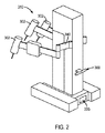
図2を参照すると、患者側カート310の例示的な実施態様が概略的に示されている。図1を参照して上述したような、ここに記載する例示的な実施態様のいずれかに従って、患者側カート310を構成し得る。例えば、患者側カート310は、1つ又はそれよりも多くの手術器具302と、1つ又はそれよりも多くの患者側マニピュレータ340とを含んでよく、患者側マニピュレータには手術器具302が連結される。患者側カート310は、患者側カートの移動を許容するよう、そのベースにホイール(図示せず)を含み得る。例えば、患者側カート310は、3つのホイール又は4つのホイールを含み得る。被駆動ホイールに推進力をもたらす患者側カートに含められる駆動システムによって、ホイールのうちの1つ又はそれよりも多くを駆動させ得る。例えば、1つの例示的な実施態様では、患者側カートの前方にあるホイールを駆動させ得るが、後方ホイールは駆動されない。患者側カートの前方は、マニピュレータが位置付けられる場所である。他の実施例では、患者側カートの後方にあるホイールを駆動させ得るし、或いは患者側カートの全てのホイールを駆動させ得る。患者側カートが駆動させられ、ホイールが地面に接するとき、駆動させられないホイールは自由に回転することが許され得る。使用者によってもたらされる操縦入力に従って操縦機構によってホイールを回転させてもよい。例示的な実施態様によれば、1つ又はそれよりも多くのホイールは、キャスターホイールに類似する構成を有し得るし、自由に回転することが許され得る。
Referring to FIG. 2, an exemplary embodiment of the
例示的な実施態様によれば、遠隔操作手術システムの患者側カート310は、図2に示すような、操縦インターフェース300を含み得る。使用者によって操縦インターフェース300に適用される力を検出するために操縦インターフェースを用いてよく、次に、操縦インターフェースは患者側カート310の駆動システムのコントローラに信号を発してよく、それは患者側カート310を所望の方法において駆動させ且つ操縦させる。図2の実施例に示すように、1つ又はそれよりも多くの手術器具202が患者側カート310の前方端に配置された状態で、操縦インターフェース300を患者側カート310の後方に取り付け得る。しかしながら、ここに記載する例示的な実施態様は、後方に取り付けられる操縦インターフェースを備える患者側カート310に限定されず、その代わりに、操縦インターフェース300を、患者側カート310の前方又は側方のような、患者側カート310の他の部分に取り付けてもよい。
According to an exemplary embodiment, the patient-
図3及び4を参照すると、遠隔操作手術システムの患者側カートのための操縦インターフェース300の例示的な実施態様が示されている。図3及び4に示す例示的な実施態様によれば、遠隔操作手術システムの患者側カートのための操縦インターフェース300をハンドルバーの形態において提供し得る。そのようなハンドルバーは、丸められた横断面を有してよく、使用者がカートを操縦するための快適でありながらもしっかりした握りをもたらすような大きさであり得る。例示的な実施態様において、ハンドル300は、例えば、約1インチ〜約2インチに及ぶ最大横方向寸法(例えば、直径)Dを有し得る。他の例示的な実施態様において、ハンドル300は、例えば、約1.5インチの最大横方向寸法(例えば、直径)Dを有し得る。しかしながら、ここに記載する例示的な実施態様の操縦インターフェースを様々な形態において提供してよく、遠隔操作手術システムの患者側カートの使用者のための操縦インターフェースの形態又は形状は、この例示的な実施態様に限定されない。例えば、患者側カートのための操縦インターフェースは、複数のハンドルバー、1つ又はそれよりも多くのハンドル、操縦ホイール、これらの形態の組み合わせ、及び操縦インターフェースのために用いられる他の形状及び形態の形態にあり得る。
Referring to FIGS. 3 and 4, an exemplary implementation of the
例示的な実施態様によれば、操縦インターフェース300は患者側カートから取り外し可能であり得る。操縦インターフェースが取り外し可能であるように構成することは、使用者が損傷した又はその他の仕方で機能しない操縦インターフェース300を他の操縦インターフェース300と交換することを許容する。例えば、図3及び4に示すように、操縦インターフェース300は、患者側カートと接触して操縦インターフェース300を患者側カートに取り付ける取付け部分306を含み得る。使用者が操縦インターフェースを比較的容易に交換するのを許容するために、操縦インターフェース300は、操縦インターフェース300を患者側カートに取り付ける1つ又はそれよりも多くの装置を含み得る。図3及び4の例示的な実施態様に示すように、操縦インターフェース300の取付け部分306は、操縦インターフェース300を患者側カートに取り付ける1つ又はそれよりも多くの締結具307(ファスナ)を含み得る。締結具307は、例えば、ボルトのようなネジ山付き締結具、又は使用者が操縦インターフェース300の取付け部分306を患者側カートから比較的容易に取り外すのを許容する他の種類の締結具であり得る。従って、使用者が操縦インターフェース300を交換することを望むとき、使用者は、例えば、1つ又はそれよりも多くの締結具307を介して、操縦インターフェース300の取付け部分306を患者側カートから取り外し、第2の操縦インターフェースの締結具及び取付け部分を介して、第2の操縦インターフェース(図示せず)を患者側カートに取り付け得る。
According to an exemplary embodiment, the
以下に更に詳細に記載するように、操縦インターフェース300は、コア/シェル構造を有してよく、コアの少なくとも一部は、取付け部分306の領域内に配置され、外側シェルは、少なくとも操縦インターフェースの左側部分302及び操縦インターフェースの右側部分304の領域内に配置される。
As described in more detail below, the
患者側カートの操縦インターフェース300を使用するために、使用者は、操縦インターフェース300を、使用者が患者側カートに動いて欲しい方向に押し得る。操縦インターフェース300を握りながら、そのような力を操縦インターフェース300に適用し得る。例えば、操縦インターフェース300が図3及び4の例示的な実施態様に示すようなハンドルバーの形態において提供されるとき、使用者は操縦インターフェース300の左側部分302及び操縦インターフェース300の右側部分304を握り得る。操縦インターフェース300が図2の実施例に示すように患者側カート310の後方に接続されるとき、使用者は操縦インターフェース300を図3に示す実質的に前方方向に押し得る。以下により詳細に記載するように、使用者によって適用される力を検出し、患者側カート310の駆動システムの制御システムに信号をもたらして患者側カート310を前方方向に移動させるように、操縦インターフェース300を構成し得る。
To use the patient side
同様に、使用者が患者側カートを後方方向に移動させたいときには、患者側カート310が後方方向に移動させられるよう、操縦インターフェース300が力を検出して、駆動システムの制御システムに信号をもたらすよう、使用者は操縦インターフェース300を図3に示す実質的に後方方向に引っ張り得る。
Similarly, when the user desires to move the patient side cart backwards, the
例示的な実施態様によれば、患者側カートの操縦インターフェースに力を適用することによって、使用者は患者側カートを所与の方向に回転させたいことを示し得る。例えば、使用者は、Y方向又は軸に沿う方向に実質的に対応し得る図3の前方方向及び後方方向に対して実質的に垂直な方向に沿って、操縦インターフェース300に横方向の力を適用し得る。
According to an exemplary embodiment, applying a force to the steering interface of the patient side cart may indicate that the user wishes to rotate the patient side cart in a given direction. For example, the user may apply a lateral force to steering
患者側カートのための所望の動きを示す使用者によって適用される力の検出のために上で議論したセンサ構造は、回転を感知すること及び/又は前後操縦制御の1つの例示的な方法であるが、他の技術も利用し得るし、相応してセンサ構造を修正し得る。例えば、他の例示的な実施態様によれば、使用者は、左側部分302及び右側部分304の一方よりも左側部分302及び右側部分304の他方により多くの力を適用することによって、患者側カートが回転させられるべきことを示し得る。操縦インターフェース300は、適用される力を検出して駆動システムの制御システムに信号を発することができ、それは駆動システムに命令して駆動システムを使用者が欲する方向に回転させる。
The sensor structure discussed above for the detection of the force applied by the user indicating the desired movement for the patient side cart senses rotation and / or in one exemplary way of back and forth steering control. Although other techniques may be used, the sensor structure may be modified accordingly. For example, according to another exemplary embodiment, the user applies the patient-side cart by applying more force to the other of left and
上記のように、操縦インターフェース300は、使用者によって操縦インターフェース300に適用される力を検出するように構成される1つ又はそれよりも多くのセンサを含み得る。図5の例示的な実施態様を参照すると、操縦インターフェース300は、コア部分310を含む操縦インターフェース300の内部構成部品を示すよう外側シェルが取り外された状態で描写されている。比較的高い応力に耐え得る材料でコア部分310を構成し得る。例えば、高強度鋼でコア部分310を製造し得るが、本開示から逸脱せずに他の高強度材料も用い得る。例示的な実施態様では、外側シェルを、例えば、アルミニウムのような金属又は金属合金で製造し得る。例示的な実施態様によれば、外側シェルは、所望の触覚的な感触を使用者にもたらすよう、使用者がハンドルに触れ或いはハンドルを握り得る場所に対応する場所に材料を含み得る。例えば、外側シェルは、そのような場所に、ゴム、プラスチック、又は他の材料を含み得る。
As mentioned above, the
操縦インターフェース300のコア部分310は、操縦インターフェース300での使用者による入力の後に患者側カートを移動させるよう、患者側カートの駆動システム(図示せず)に信号を送信するように構成される1つ又はそれよりも多くのセンサを含み得る。例えば、図5に示すように、操縦インターフェース300は、操縦インターフェース300の左側部分302内に取り付けられる第1のセンサ320と、操縦インターフェース300の右側部分304内に取り付けられる第2のセンサ322とを含み得る。換言すれば、センサ320,322を操縦インターフェース300の実質的に反対の部分に設け得る。操縦インターフェース300の異なる部分にセンサ320,322を備える操縦インターフェース300を提供することによって、使用者は、操縦インターフェース300に対する異なる位置に自分自身を有利に位置付け、片手又は両手で力を適用し、よって、センサ320,322の一方又は両方に力を適用して、患者側カートの操縦及び動作に関する同じ結果を達成し得る。そのような構造は、例えば、使用者が患者側カートの後方に位置付けられるときに患者側カートの前方における環境を観察する使用者の能力を助長するのに役立ち得る。使用者が患者側カートの直ぐ後に位置して操縦インターフェース300を操作することが求められるならば、使用者の眺め(ビュー)は、患者側カートによって、例えば、患者側カートのマニピュレータアーム部分によって妨げられ得る。使用者が操縦インターフェース300の相対的に一方の側に位置付けられることを許容することによって、使用者は患者側カートの一方の側に立ち、操縦インターフェース300で片手を使用し、患者側カートの前方における環境の改良された眺め(ビュー)を有し得る。
The
図3の前方方向及び後方方向において使用者によって操縦インターフェース300に適用される力を検出するようにセンサ320,322を構成し得るし、患者側カート310を回転させるよう使用者によって操縦インターフェース300に適用される力を検出するようにセンサ320,322を構成し得る。図3の前方方向及び後方方向は、X方向又は軸に沿う方向に実質的に対応し得るし、図3の前方方向及び後方方向に対して実質的に垂直な方向は、Y方向又は軸に沿う方向に実質的に対応し得る。
The
図6を参照すると、第1のセンサ320の例示的な実施態様が示されている。以下の議論は、操縦インターフェース300の左側部分302に取り付け得る第1のセンサ320の構成及び機能に関するが、操縦インターフェース300の右側部分304に取り付け得る第2のセンサ322は、第1のセンサ320と同じ機能及び構成を有し得る。
Referring to FIG. 6, an exemplary implementation of the
使用者によって適用される力は、図5に示すX及び/又はY方向における成分を含み得るので、センサ320は、1つ又はそれよりも多くの方向における力を検出する機能を含み得る。例示的な実施態様によれば、センサ320は、図5及び6に示すX及びY方向における力を検出する機能を含み得る。例えば、センサ320は、図5及び6中のX方向に沿って使用者によって適用される力を測定する第1の検出装置323と、図5及び6中のY方向に沿って使用者によって適用される力を測定する第2の検出装置324とを含み得る。図5及び6に示すように、X方向及びY方向は互いに直交し合う。従って、使用者によって操縦インターフェース300に適用される力がX及びY方向のいずれかに完全に整列させられないとしても、適用される力の成分をX及びY方向において測定し得る。
Because the force applied by the user may include components in the X and / or Y directions shown in FIG. 5,
様々な例示的な実施態様において、操縦インターフェースにおいて用いられるセンサは、X及びY方向に対して直交する(図5及び6の実施態様に示していない)垂直Z方向における力を検出することも可能であり得る。しかしながら、垂直Z方向における力を検出し得るセンサは任意的であり、操縦インターフェース300は、X及びY方向における力を検出するセンサのみを含み得る。
In various exemplary embodiments, sensors used in the steering interface may also detect forces in the vertical Z direction (not shown in the embodiments of FIGS. 5 and 6) orthogonal to the X and Y directions. It can be. However, sensors capable of detecting force in the vertical Z direction are optional, and the
例えば、使用者が操縦インターフェース300を横向きに押し、引き、或いは移動させて、患者側カートを移動させたいことを示すときに、使用者によって操縦インターフェース300に適用される比較的小さい力を検出するように検出装置323,324を構成し得る。例えば、検出装置323,324は、人によって操縦インターフェース300に適用される力を検出するのに十分な程に感応的であり得る。例えば、検出装置323,324は、平均的な大人の体重及び大きさを有する人によって適用される力を検出するのに十分な程に感応的であり得る。例示的な実施態様によれば、検出装置323,324は、例えば、約0.1ポンド〜約100ポンドに及ぶ力を検出し得る。他の例示的な実施態様によれば、検出装置323,324は、例えば、0.4ポンド〜約25ポンドに及ぶ力を検出し得る。例示的な実施態様によれば、例えば、カートの大きさ及び/又は重量及び/又はカートの移動中に使用者によって必要とされるのが望ましい力の行使のような要因に基づき、センサの力感度の範囲を選択し得る。
For example, detecting a relatively small force applied by the user to the
センサ320の検出装置323,324は、センサ320によって適用される力を検出して適用される力に対応する電気信号をもたらすように構成される素子(component)であり得る。例えば、検出装置323,324は、ひずみ計であり得る。各検出装置323,324は、適用される力を測定する単一の装置であり得るし、或いは適用される力を検出する複数の装置を含み得る。
The
例示的な実施態様によれば、検出装置323,324は、それぞれ、センサの検出装置の1つが故障する場合においてセンサ320,322が余剰な検出装置を有するよう、X及びY方向において適用される力を検出する複数の装置を含み得る。例えば、検出装置323及び/又は検出装置324は、余剰な検出装置を有利にもたらすよう、X及びY方向の各々において一次及び二次検出素子(図示せず)を含み得る。
According to an exemplary embodiment,
よって、検出装置323,324の一次又は二次検出素子の一方が故障するようなことがあれば(一次又は二次検出素子の一方のための接続部又は制御電子機器を含む)、検出素子323,324は、機能している一次及び二次検出素子の他方を有し、操縦インターフェース300に適用される力を検出する機能を依然として遂行し得る。換言すれば、検出装置323,324の余剰な一次又は二次検出素子は、例えば、一次及び二次検出素子が同調しないならば、カート動作を制限することによって、予期しないカート動作を防止し或いは最小限化し得る安全予防措置として働き得る。他の例示的な実施態様によれば、二次検出素子を一次検出素子に対する余剰なバックアップとして設けてよく、或いはその逆でもよい。この場合には、検出装置323,324の一次又は二次検出素子の1つが故障するようなことがあれば、全センサ320,322又は操縦インターフェース300が交換される必要はない。更なる実施例において、検出装置223は、X方向における力を検出する一次ひずみ計及び二次ひずみ計を含んでよく、検出装置224は、Y方向における力を検出する一次ひずみ計及び二次ひずみ計を含んでよい。
Thus, if one of the primary or secondary detection elements of the
例示的な実施態様によれば、センサ320は、センサ320に電気信号を送信し且つセンサ320から電気信号を送信するために用い得る1つ又はそれよりも多くの電気端子326を更に含み得る。図7の実施例に示すように、センサ320の底面327は、センサ320を操縦インターフェース300、例えば、操縦インターフェース300のコア部分310に取り付ける1つ又はそれよりも多くのマウント328(取付台)を含み得る。
According to an exemplary embodiment,
使用者が操縦インターフェース300に力を適用するときに、センサ320,322は力及び歪みに晒されるので、特に、一部のひずみ計センサは比較的小さい変位(例えば、力)を検出するように設計され、操縦インターフェースに適用される力は比較的大きくあり得るので、センサ320,322は損傷を受け得る。この問題に対処するために、センサ320,322を潜在的に損傷させ得るセンサに対する過剰な力を制限することによって、センサ320,322に対するある程度の保護をもたらす1つ又はそれよりも多くの装置を用いて、センサ320,322を操縦インターフェース300内に取り付け得る。そのような保護装置は、コンプライアント(compliant)であり且つベンド(bend)である様々な装置のうちのいずれかであり得る。加えて、保護装置はセンサに許容される動きの量を制限し得る。換言すれば、操縦インターフェースに適用される比較的大きな変位をセンサ320,322の比較的小さな変位に変換するために保護装置を用い得る。そのような装置は、例えば、バネ、(例えば、曲げ及び/又は捩りを通じて)撓むように構成されるバー又はロッド、エラストマー材料、及びシェル部分312がコア部分310に対して移動するときにセンサ320,322の周りに追加的なコンプライアンス(compliance)をもたらすように構成される他の種類の装置を含み得る。
In particular, some strain gauge sensors detect a relatively small displacement (e.g. force) since the
例えば、図8の例示的な実施態様に示すように、ある程度の保護をセンサ320にもたらすようセンサ320に対して構成され且つ配置される1つ又はそれよりも多くのバネ332を用いてセンサ320を取り付け得る。センサ320、センサハウジング331、及びバネ332は、センサブロック330を共に形成してよく、バネ332がセンサ320と操縦インターフェース300の残余との間に追加的なコンプライアンスをもたらすよう、バネ332を介してセンサブロック330を操縦インターフェース300内に取り付け得る。
For example, as shown in the exemplary embodiment of FIG. 8,
例えば、図9の例示的な実施態様に示すように、センサ320を操縦インターフェース300のコア部分310に取り付けることによって、並びに1つ又はそれよりも多くのバネマウント334を介して1つ又はそれよりも多くのバネ332を操縦インターフェース300のカバー部分312に取り付けることによって、(図9の断面に示す)センサブロック330を操縦インターフェース300内に含め得る。換言すれば、バネ332はセンサ320をカバー部分312に接続し得る。カバー部分312は、例えば、(図9の実施例に示すような)コア部分310の周りのシェルの形態、1つ又はそれよりも多くの平坦な又は湾曲した表面の形態、又は他の形態のカバーであり得る。
For example, as shown in the exemplary embodiment of FIG. 9, by attaching the
例示的な実施態様によれば、操縦インターフェース300のコア部分310及びカバー部分312は、センサ320,322のセンサブロック330によってもたらされるものを除き、構造的な接続部を欠き得る。従って、そのような実施態様では、操縦インターフェース300の1つ又はそれよりも多くのセンサのセンサブロック330によってもたらされる構造接続部が、操縦インターフェース300のコア部分310とカバー部分312との間の唯一の接続部を提供し得る。換言すれば、操縦インターフェース300が単一のセンサブロック330を含むならば、センサブロック330は、コア部分310とカバー部分312との間の唯一の接続部を提供し得る。操縦インターフェース300が複数のセンサブロック330を含むならば、センサブロック330は、コア部分310とカバー部分312との間の唯一の接続部を集合的にもたらし得る。例えば、センサブロック330のバネ332、ハウジング331、及びバネマウント334によって提供される接続部は、コア部分310とカバー部分312との間の唯一の接続物を提供し得る。このようにして、カバー部分312及びコア部分310は、互いに対して「浮動している」(“floating”)と考えられ得る。例示的な実施態様によれば、センサブロック330によるコア部分310からのカバー部分312の懸架の故に、カバー部分312は、コア部分310に対して「浮動している」と考えられ得る。例えば、コア部分310が患者側カートに接続されるならば、カバー部分312はコア部分310に対して動くように思われ得る。他の例示的な実施態様によれば、例えば、カバー部分312がコア部分310の代わりに患者側カートに接続されるときに、コア部分310は、カバー部分312に対して「浮動している」と考えられ得る。
According to an exemplary embodiment,
操縦インターフェースに対して力が適用されて、例えば、患者側カートの使用者の所望の動作方向を示すとき、力はカバー部分312に対して適用され、コア部分310とカバー部分312との間に配置されるセンサブロック330によってもたらされる懸架構造の故に、バネ332を介してセンサ320に伝達され得る。バネ332は比較的可撓な要素であるので、バネ332は、同じ使用者適用される力に関して、コア部分310に対するカバー部分312の追加的な運動を有利に可能にし得る。結果的に、操縦インターフェースのコア部分310とカバー部分312との間にセンサブロック330を取り付けてよく、ネは操縦インターフェース300に追加的なコンプライアンスをもたらす働きをする。
The force is applied to the
図9に示すように、様々な例示的な実施態様において、距離Aを有する間隙をコア部分310とカバー部分312との間に設け得る。その間隙を全ての方向においてコア部分310とカバー部分312との間に設け得る。間隙は、例えば、約0.04インチ〜約0.07インチに及ぶ距離Aを有し得る。他の実施例において、間隙は、約0.045インチ〜約0.065インチに及ぶ距離Aを有し得る。コア部分310とカバー部分312との間の比較的小さな間隙は、カバー部分312及びコア部分310が互いに対して動くことを許容し得る。そのような相対的な動きは、使用者によって適用される力が比較的容易にセンサ320,322に伝達されることを可能にし得る。そのような構成を備える操縦インターフェース300は、比較的「柔らかい」(例えば、コア部分310とカバー部分312との間のより高い程度の相対的な動きを許容する)操縦インターフェースを有利に回避することがあり、それはセンサに対する適用される力の有意な変化を引き起こし得る望ましくないフィードバックループを招き得るし、意図せずに振動する患者側カートの運動を招き得る。更に、例示的な実施態様によれば、コア部分310とカバー部分312との間の動きが人間の知覚には感知できないか或いは取るに足りないよう、間隙は十分に小さい。よって、使用者はコア部分310に対するカバー部分312の動きに気付かないかもしれず、ひいては、それは患者側カートを運転している間の操縦インターフェースへの力の適用中にしっかりした高品質の感触を使用者に与え得る。よって、操縦インターフェース300は、使用者によって適用される力を検出するその機能をもたらしながら、堅固な構造及び技能(craftsmanship)の外観も提示し得る。
As shown in FIG. 9, in various exemplary embodiments, a gap having a distance A may be provided between the
例示的な実施態様によれば、操縦インターフェース300は、使用者によって操縦インターフェースに適用される力に起因するコア部分310とカバー部分312との間の相対的な動きの量を制限する機械的ストッパ(stop)を含み得る。よって、機械的ストッパはセンサに適用される力及び歪みの量を制限し得る。図10の部分的な内部平面図を参照すると、図10は、操縦インターフェース300のカバー部分312が、上述のように、センサブロック330及びそのバネ332によってコア部分310から懸架され、コア部分310の端部分314が、カバー部分312内に形成される凹部317内に延びる突起316を含み得ることで、凹部317を取り囲むカバー部分312の内表面部分と突起316との間に間隙318がもたらされることを示している。加えて、コア部分310の端部分314とカバー部分312の内壁319との間に間隙315を設け得る。
According to an exemplary embodiment, steering
比較的大きな力が操縦インターフェース300に対して適用されるときには、適用される力をセンサブロック330のセンサ320に適用し得る。これはセンサ320に適用される大きな歪みを引き起こすことがあり、歪みが過剰であるならば、それはセンサ320に損傷を引き起こし得る。相対的に大きな力及び歪みは、コア部分310及びカバー部分312を互いに対して移動させ、潜在的には、突起316を、凹部317を形成するカバー部分312の壁と接触させ得る。代替的に或いはこの移動に加えて、端部分314は、内表面部分319と接触するようになり得る。突起316が凹部317を形成するカバー部分312の内表面部分と接触し且つ/或いは端部分314が内壁319と接触するときに、コア部分310とカバー部分312との間の更なる動きは停止されるので、センサ320に適用される歪みの量は制限される。結果的に、大きな力及び歪みによってセンサ320に引き起こされる過荷重及び損傷を最小限化し或いは防止し得る。加えて、バネ332はセンサブロック330のために強化されたコンプライアンスをもたらす。よって、センサブロック330は、コア部分310とカバー部分312との間の間隙内で合理的な製造公差を許容すると同時にセンサ320の変位を比較的少量に制限する、費用効果的な設計を有し得る。例えば、例示的な実施態様において、コア部分310とカバー部分312との間の約0.065インチの動きは、約0.010インチのセンサ320の変位を引き起こし得る。
When a relatively large force is applied to steering
例示的な実施態様によれば、センサ320,322及びセンサブロック330が完全に取り囲まれるように、センサ320,322及びそれらのそれぞれのセンサブロック330を操縦インターフェース300内に含め得る。結果的に、センサ320,322及びセンサブロック330は完全に覆われ、操縦インターフェース300の外表面上で晒されなくてよい。例えば、センサ320,322が、例えば、外部環境に晒されないよう、操縦インターフェース300のカバー部分312は、センサ320,322を完全に取り囲み得る。他の実施例では、使用者がセンサ320,322の少なくとも一部を見ることができるよう、センサ320,322の一部を操縦インターフェース300の外表面で露出させ得る。
According to an exemplary embodiment, the
例示的な実施態様によれば、操縦インターフェース300は、使用者が操縦インターフェース300に力を適用するときに、操縦インターフェース300の可撓性及び動作を制御する1つ又はそれよりも多くの装置を含み得る。そのような装置を用いて、例えば、使用者が操縦インターフェース300に力を適用するときに、操縦インターフェース300が、操縦インターフェース300を取り付ける患者側カートに対してどのように動くかに影響を及ぼし得る。センサブロック330のバネ332を含む上述のセンサブロック330に加えて、そのような装置を設け得る。
According to an exemplary embodiment, steering
図11を参照すると、操縦インターフェース300の例示的な実施態様が示されており、図11では、安定化装置340が、操縦インターフェース300のコア部分310とカバー部分312との間に配置されている。例示的な実施態様によれば、安定化装置340は、X又はY方向以外の方向における操縦インターフェースの運動を防止し得る。更に、安定化装置340を設けて、コア部分310に対するカバー部分312の動きの量を制御し得る。例えば、使用者は、図11の例示的な実施態様に示すように、回転モーメントMを操縦インターフェース300に適用し得る。操縦インターフェース300が患者側カートに対してモーメントMによって示す方向に動くならば、使用者は患者側カートが操縦インターフェース300の動きの結果として何らかの方法において応答しなければならないという印象を有し得る。従って、そのような動きを最小限化する或いは防止する安定化装置340を用いることは、患者側カートが操縦インターフェース300でのそのような入力に応答すると、使用者が誤って考えることを回避し得る。加えて、操縦インターフェースが、操縦インターフェース300が取り付けられる患者側カートに対してモーメントMによって示す方向に動くならば、特に運動が突然であり滑らかでないならば、使用者は操縦インターフェース300が緩いか或いは良好に作製されていないという感覚を有し得る。
Referring to FIG. 11, an exemplary embodiment of the
安定化装置340は、使用者が操縦インターフェース300に力を提供するときに起こる運動に抗するように作用することがあり、それは操縦インターフェース300をその初期位置から離れる方向(例えば、図11中のモーメントMによって引き起こされる方向)に移動させ得るし、使用者が適用される力を解放するときに起こる運動に抗するように作用することがあり、それは操縦インターフェース300をその初期位置に向かう方向に移動させ得る。例えば、安定化装置340は、例えば、コア部分310に対して適用される力の約10%〜約15%に及ぶ量の力を反らすことによって、運動に抗し得る。更に、安定化装置340のこの反らし機能(shunting function)は、実質的にX、Y、及びZ方向に沿う直線方向において操縦インターフェースの運動を許容するように作用し得る。これらの運動に抗する方法において作用することによって、安定化装置340は運動が起こることを許容するが、突然の発作的な運動というよりもむしろ、使用者にとって人間工学的に望ましい滑らかな運動をもたらす方法において許容する。図11の例示的な実施態様に示すように、減衰装置340は、例えば、操縦インターフェース300のコア部分310とカバー部分312との間に取り付けられるコイルバネであり得る。更なる実施例において、バネは、機械加工バネ又は当業者が精通している様々な衝撃吸収機構のうちのいずれかであり得る。バネ以外の他の機構を安定化装置として用い得る。例示的な実施態様では、一対の永久磁石を用いて安定化装置340を提供し得る。
例示的な実施態様によれば、操縦インターフェース300は、患者側カートの駆動制御システムに信号を送信して患者側カートのための運動を作動させる装置を含み得る。例えば、操縦インターフェースのセンサは操縦インターフェースに適用される力に関する信号を常に送信し得るが、センサが操縦インターフェースに力が適用されていることを示すとしても、患者側カートの運動が起こるべきでないことを示す信号をもたらして患者側カートの偶発的な運動を防止する装置を設けることが望ましくあり得る。換言すれば、操縦インターフェースは、操縦インターフェースのセンサによって発せられる第1の信号と無関係な第2の信号を発する第2の装置を含み得る。操縦インターフェースの第2の装置に適用される力が十分な大きさを有するならば、第2の装置は、適用される力が所望の動きを表すことを示す信号を発し得る。さもなければ、第2の装置に適用される力が十分でないならば、第2の装置は、患者側カートが動くべきであることを示す信号を発しない。信号が操縦インターフェース30のセンサから患者側カートの駆動システムのためのコントローラに発せられており、そして、使用者が操縦インターフェース300に力を適用していないか或いは操縦インターフェース300に適用される力が患者側カートのための所望の運動を表さないとき、そのような装置は、患者側カートの偶発的な運動を防止することによって、ある程度の安全をもたらし得る。
According to an exemplary embodiment, the
図12を参照すると、操縦インターフェース300の例示的な実施態様が示されており、操縦インターフェース300は、接点スイッチ352と、接点トリガ350とを含む。接点スイッチ352と接点トリガ350との間の相対的な動きを許容するよう、接点スイッチ352及び接点トリガ350を操縦インターフェース300内に取り付け得る。具体的には、使用者が接点トリガ350の露出部分を押して接点トリガ350を接点スイッチ352に対して移動させ且つ接点トリガ350と接点スイッチ352との間の係合を引き起こすよう、接点トリガ350の少なくとも一部がカバー部分312の外表面上で露出させられた状態で、接点トリガ350及び接点スイッチ352の両方をカバー部分312内に取り付け得る。
Referring to FIG. 12, an exemplary embodiment of
使用者が操縦インターフェース300に力を適用するとき、相対的な運動が操縦インターフェース300のコア部分310とカバー部分312との間に起こり、操縦インターフェース300のセンサ320は適用される力を示す信号を発し得る。しかしながら、接点トリガ350が適切に係合させられないならば、そのような適用される力は患者側カートの動きをもたらし得ない。患者側カートのための所望の動きを示すために、接点トリガ350を押して接点トリガ350と接点スイッチ352との間の係合を引き起こし得る。十分な力が接点トリガ350に適用されて接点トリガ350と接点スイッチ352との間の係合を引き起こすとき、接点スイッチ352は患者側カートの駆動システム又はコントローラに信号を発して、患者側カートが操縦インターフェースのセンサから発せられる信号に従って動くべきであることを示し得る。よって、接点スイッチ352及び接点トリガ350は、使用者が操縦インターフェース300に力を適用して接点トリガ350を押すときに患者側カートの運動が許容されるが、使用者が操縦インターフェース300の接点トリガ350を解放するか或いはさもなければ接点トリガ350に力を適用しないときに患者側カートの運動が許容されないよう、「デッドマンズ」(dead man’s)スイッチとして働き得る。
When the user applies a force to the
接点スイッチ352及び接点トリガ350が係合させられないとき、操縦インターフェース300、例えば、接点スイッチ352は、患者側カートの偶発的な運動が回避されるよう、患者側カートが操縦インターフェース300のセンサによって発せられる信号に従って動くべきでないことを示す信号を発し得る。代替的に、接点スイッチ352及び接点トリガ350が係合させられないときに、操縦インターフェース300から、例えば、接点スイッチ352から信号を発しないで、患者側カートが動くべきであることを示してよく、患者側カートの駆動システム又はコントローラは、そのような信号の欠如を、運動が起こるべきでないと解釈し得る。
When the
更なる実施例では、使用者が接点トリガ350に力を適用しないときに、接点トリガ350が「オフ」位置に付勢されるよう、接点スイッチ352及び接点トリガ350の少なくとも1つを取り付け得る。例示的な実施態様では、1つ又はそれよりも多くの板バネ354を用いて、接点トリガ350を取り付け得るが、そのような付勢装置は例示的であり且つ非限定的であるに過ぎない。他の例示的な実施態様では、コイルバネ、バネ荷重押しボタン、又は弾性的に変形可能な構成を含む他の構成のような、戻りバネを備える旋回レバー(図示せず)を用いて、接点トリガ350を取り付け得る。
In a further embodiment, at least one of the
操縦インターフェース300は、複数の接点スイッチ352及び接点トリガ350を含み得る。例えば、使用者が操縦インターフェース300の左側部分302の接点トリガ又は右側部分304の接点トリガを押して、操縦インターフェース300が取り付けられる患者側カートの運動をアクティブ化するように、操縦インターフェース300の左側部分302及び右側部分304の各々が、接点スイッチ352及び接点トリガ350を含み得る。代替的な例示的な実施態様では、患者側カートの運動をアクティブ化するために接点トリガの1つよりも多くが作動させられることを必要とするように操縦インターフェース300を構成し得る。更に、接点トリガ350は機械的接点の形態である必要はなく、当該技術分野において用いられる他のスイッチ装置の形態を取り得る。
The
操縦インターフェース300のセンサブロック330において用いられるセンサ320,322は互いに異なってよく、互いに異なる出力をもたらしてよい。特に1つの操縦インターフェースが取り外されて異なるセンサを有する他の操縦インターフェースと交換されるときに、これは患者側カートの駆動システムのためのコントローラに対するセンサ320,322のキャリブレーションを必要とし得る。この問題に対処するために、操縦インターフェース300が患者側カートに取り付けられ、操縦インターフェース300の構成部品が患者側カートの駆動システムのためのコントローラに接続されるときに、センサからの出力が使用者からの追加的な労力を伴わずに自動的にキャリブレートされるように、操縦インターフェース300は、キャリブレーション装置を含み得る。例えば、操縦インターフェース300は、図13の例示的な実施態様に示すような、データ記憶装置360を含み得る。
The
キャリブレーションデータ記憶装置360は、例えば、フラッシュメモリ又はキャリブレーションデータを格納する他の種類のメモリのような、例えば、電気消去可能なプログラマブル読出し専用メモリ(EEPROM)装置であり得る。以下に議論するように、操縦インターフェース300が患者側カートに取り付けられるときに患者側カートのための駆動システムのコントローラと信号接続してキャリブレーション装置360を配置し得る。加えて、操縦インターフェース300が患者側カートに取り付けられるときに、センサ320,322とセンサブロック330との間に接続がなされるよう、電線又はワイヤのようなセンサブロック330のための接続部が、操縦インターフェース300の側方部分362に沿って延び得る。
図14は、例示的な実施態様に従った患者側カートとの接続状態にある操縦インターフェースシステムの概略的なブロック図を描写している。図14に示すように、操縦インターフェース300が患者側カート1510に取り付けられるとき(様々な例示的な実施態様において患者側カート1510を図1の例示的な実施態様におけるカート110又は210のように構成し得る)、センサ220,222をカート110と信号接続して配置してよく、カート110は、上述のように、駆動システムのための制御プロセッサを含んでよい。使用者が接点スイッチを接点トリガ350と係合させるのに十分な力を操縦インターフェース300の接点トリガに適用するときに、接点スイッチ352のうちの少なくとも1つからの信号のような信号を操縦インターフェース300からカート1510に発して、カート1510の駆動システムがセンサ320,322からの信号に従ってカート1510を動かすように作用しなければならないことを示し得るように、カートと操縦インターフェース300内の接点スイッチ352との間で接続を行ってもよい。更に、操縦インターフェース300がカート1510に取り付けられるときにコントローラにキャリブレーションデータを提供し得るように、キャリブレーション装置360とカート1510との間の接続も行い得る。カート1510の装置によって操縦インターフェース300からカート1510にもたらさせる信号を増幅させ得る。加えて、カート1510は、操縦インターフェース300から受信するあらゆる信号を必要に応じて調整するアナログ/デジタル変換器を含み得る。
FIG. 14 depicts a schematic block diagram of a steering interface system in connection with a patient side cart in accordance with an illustrative embodiment. As shown in FIG. 14, when the
操縦インターフェース300のセンサ320,322は、使用者によって操縦インターフェース300に適用される力を検出するように設計される。上で議論したように、センサ320,322は、センサ320,322に適用される歪みの量を検出して対応する信号をもたらすひずみ計であり得る。ひずみ計のための1つの設計は、ホイートストンブリッジを含む。図15は、第1のセンサ375と、第2のセンサ377とを含む、回路図を描写している。第1のセンサ375及び第2のセンサ377の各々は、完全なホイートストンブリッジを含み、完全なホイートストンブリッジは、例示的な実施態様によれば、4つのセンサ要素370を含む。回路は、更に、各センサのための増幅器374と、回路に亘る電圧を測定する素子376とを含む。数字371は、ケーブル及び/又はコネクタに起因する抵抗を指している。図15に示す回路において、ケーブル及び/又はコネクタに起因する抵抗371は、センサ応答において比較的小さな誤差(エラー)を引き起こす。しかしながら、抵抗371からのこれらの誤差を増幅器374によって補償して除去することができ、それは異なるブリッジ増幅器を形成し得る。
The
図15の例示的な実施態様に示すような完全なホイートストンブリッジを用いる構成は、各々が4つのセンサ要素370を含むセンサ375,377をもたらす。ここにおいて議論した例示的な実施態様のうちの1つにおけるハンドルのような装置が、ハンドルの各端にX及びY方向の各々のためにセンサを含むならば、その構成は装置のために全部で16個のセンサ要素370をもたらす。更に、余剰の組のセンサが設けられるならば、センサ要素370の総数は倍加されて32個になる。
The configuration using a complete Wheatstone bridge as shown in the exemplary embodiment of FIG. 15 results in
操縦インターフェース300のセンサ320,322に関する1つの懸念は、カートに運動をもたらすためにカート駆動システムによって用いられる人によって適用される力を測定するためにセンサ320,322が用いられることである。ある用途において、センサ320,322は、そのようなセンサを利用し得る、例えば、重量測定又は他の感応的な力の測定を行うことのような、他の用途の精度を必要としなくてもよい。従って、各センサ320,322は、図15に示す構成を含むセンサの精度を有する必要はなく。その代わり、センサ320,322の精度はより低くてもよく、それはより安価であり得るセンサの構成を有利に許容する。例えば、ひずみ計が用いられるならば、センサ320,322は、図16の例示的な実施態様に示す構成を有し得る。
One concern with the
図16の例示的な実施態様に示すように、センサ320がホイートストンブリッジの2つのセンサ要素370(ホイートストンブリッジの2分の1)を含み、センサ322がホイートストンブリッジの他の2つのセンサ要素372(ホイートストンブリッジの他の2分の1)を含むように、ホイートストンブリッジを分割し得る。図16に示す構成は、増幅器374と、図16の回路に亘る電圧を測定する素子376とを更に含み得る。よって、ハンドルのような装置によって利用されるセンサ要素370,372の総数を半分に減らすことができ、それは装置を製造する費用を有利に減少させる。更に、より少ない増幅器374を用いることによって、追加的な費用節約をもたらし得る。何故ならば、1つの増幅器374のみを用い得るからである。
As shown in the exemplary embodiment of FIG. 16, the
各センサ320,322のためにより少ないセンサ要素370,372を用いる潜在的な結果は、センサ出力により大きな誤差(エラー)があり得ることである。例えば、ケーブル及び/又はコネクタに起因する抵抗371が、図16の例示的な実施態様に示す増幅器374によって除去されない誤差を生成し得る。図16の例示的な実施態様に示すような分割ホイートストンブリッジを用いる構成は、図15の構成を有するセンサよりも精度が低いセンサ320,322をもたらし得るが、センサ320,322、人によって操縦インターフェース300に適用される力を検出するには十分に正確であり得る。しかしながら、例示的な実施態様によれば、分割ホイートストンブリッジの精度を増大させ得る。例えば、単一の対のワイヤの代わりに4つの対のワイヤを備えるブリッジに電力供給してケーブル抵抗からの誤差を減少させることによって、単一の対のコネクタ接点の代わりに4つの対のコネクタ接点を用いてコネクタ誤差を減少させることによって、コネクタ接点のために耐食性材料を用いてコネクタ接点の長期老化からの誤差を減少させることによって、センサ320,322のためのケーブルの長さを実質的に同じケーブル抵抗を有する実質的に同じ長さであるように特定してセンサ320,322の間のケーブル抵抗の差に起因する誤差を減少させることによって、及び/又は、上で議論したキャリブレーションデータ記憶装置内に格納されるキャリブレーション値のような装置内に格納されるキャリブレーション値を介して残留ケーブル及び/又はコネクタ抵抗を除去することによって、例えば、分割ホイートストンブリッジによって生成される誤差を減少させ得る。
The potential result of using
他の実施態様によれば、患者側カートは、蹴板(kick plate)を含み得る。図2の例示的な実施態様に示すように、センサを有する蹴板303を患者側カートの後方、例えば、操縦インターフェースが配置されるカートの側方に配置し得る。使用者が地面から離れて操縦インターフェース300に力を適用するときの状況に従って操縦インターフェース300を設計し得る。しかしながら、使用者が患者側カートを前方に移動させるのを助ける試みにおいて患者側カートの背面に足を置くと同時に、操縦インターフェース300を保持するならば、X(後方)方向に操縦インターフェースを引き戻す傾向があり得る。この状況では、操縦インターフェース300に適用される力はX(後方)方向にあるので、使用者が使用者の足を用いることによってカートを前方に動かすことを試みているとしても、カートは使用者に向かって後方方向に後向きに動く。この状況を防止するために、使用者が蹴板303を作動させるか(engage)或いは叩く(strike)ときに、カートを駆動させるよう電力供給するのを停止する信号を送信するよう、蹴板303を構成し得る。例示的な実施態様によれば、蹴板303が押され且つカートが後方方向に移動させられるならば、蹴板303はカートの動きを無効にし得る。
According to another embodiment, the patient side cart may include a kick plate. As shown in the exemplary embodiment of FIG. 2, a
使用者によって適用される力を簡単な方法において検出する操縦インターフェースを提供することによって、使用者は、操縦インターフェースが取り付けられる患者側カートを比較的容易に有利に移動させ得る。例えば、カートは、使用者が患者側カートを補助なしで移動させるのに必要な力を提供することを要求せずに比較的大重量の患者側カートを移動させる駆動システムを含み得る。加えて、使用者が多数の複雑な制御装置と相互作用することを必要とせずに、患者側カートがどの方向に駆動させられるべきかを制御システムが決定し得るよう、操縦インターフェースは、使用者によって操縦インターフェースに適用される力を検出する単一のユーザインターフェースを提供し得る。更に、操縦インターフェースは、そのしっかりした構成及び比較的滑らかな動きを介して、使用者に操縦インターフェース及び患者側カートの技能(craftsmanship)についての肯定的な感触を有利にもたらし得る。 By providing a steering interface that detects the force applied by the user in a simple manner, the user can advantageously move the patient-side cart on which the steering interface is mounted relatively easily. For example, the cart may include a drive system that moves the relatively heavy patient-side cart without requiring the user to provide the necessary force to move the patient-side cart without assistance. In addition, the steering interface allows the user to determine in which direction the patient side cart should be driven without requiring the user to interact with a large number of complex controls. Can provide a single user interface that detects the force applied to the steering interface. Furthermore, the steering interface may advantageously provide the user with a positive feel about the craftsmanship of the steering interface and the patient side cart through its solid configuration and relatively smooth movement.
データを格納し、抽出し、処理し、且つ/或いは出力し、且つ/或いは他のコンピュータと通信し得る(非限定的な実施例における)任意のコンピュータのような、計算ハードウェア(計算装置)及び/又はソフトウェアにおいて、ここに記載する様々な方法を含む例示的な実施態様を実施し得る。処理された結果を計算ハードウェアのディスプレイ上に表示し得る。本開示の様々な例示的な実施態様に従った様々な応答及び信号処理に影響を与えるアルゴリズムを含む1つ又はそれよりも多くのプログラム/ソフトウェアを、コアプロセッサを含む制御装置カートのデータインターフェースモジュールのようなプロセッサによって又はそのような制御装置カートと共に実施し得るし、コンピュータ可読の記録及び/又は記憶媒体を含むコンピュータ可読の媒体上に記録し得る。コンピュータ可読の記録媒体の実施例は、磁気記録装置、光ディスク、光磁気ディスク、及び/又は半導体メモリ(例えば、RAM、ROM等)を含む。磁気記録装置の実施例は、ハードディスクドライブ(HDD)、フレキシブルディスク(FD)、及び磁気テープ(MT)を含む。光ディスクの実施例は、DVD(デジタル多用途ディスク)、DVD−RAM、CD−ROM(コンパクトディスク−読出し専用記憶装置)、及びCD−R(録画可能)/RW)を含む。 Computing hardware, such as any computer (in non-limiting embodiments) capable of storing, extracting, processing, and / or outputting data, and / or communicating with other computers Exemplary embodiments may be implemented in software, including the various methods described herein. The processed results may be displayed on a display of computing hardware. Controller cart data interface module including core processor, with one or more programs / software including algorithms that affect various responses and signal processing according to various exemplary embodiments of the present disclosure May be implemented by a processor such as or with such a controller cart, and may be recorded on a computer readable medium, including computer readable recording and / or storage medium. Examples of computer readable recording media include magnetic recording devices, optical disks, magneto-optical disks, and / or semiconductor memory (eg, RAM, ROM, etc.). Examples of magnetic recording devices include hard disk drives (HDDs), flexible disks (FDs), and magnetic tapes (MTs). Examples of optical disks include DVD (Digital Versatile Disk), DVD-RAM, CD-ROM (Compact Disk-Read Only Storage), and CD-R (Recordable) / RW).
更なる変形及び代替的な実施態様は、ここにおける開示の観点から当業者に明らかであろう。例えば、システム及び方法は、操作の明瞭性のために図面及び記載から省略した追加的な素子又はステップを含み得る。従って、この記載は例示的であるに過ぎず、本教示を実施する一般的な方法を当業者に教示する目的のためであると解釈されるべきである。ここに示し且つ記載する様々な実施態様は例示として取られるべきことが理解されるべきである。要素及び材料並びにそれらの要素及び材料の構成をここに例示し且つ記載するものと置換してよく、部品及びプロセスを逆転させてよく、本教示の特定の機能を独立して利用してよく、全てはここにおける記載の利益を得た後で当業者に明らかであろう。本教示及び後続の請求項の精神及び範囲から逸脱せずに、ここに記載した要素における変更を行い得る。 Additional variations and alternative embodiments will be apparent to those skilled in the art in view of the disclosure herein. For example, the systems and methods may include additional elements or steps that are omitted from the drawings and descriptions for clarity of operation. Accordingly, this description is exemplary only and should be construed as for the purpose of teaching those skilled in the art the general manner of practicing the present teachings. It should be understood that the various embodiments shown and described herein are to be taken as illustrative. The elements and materials as well as their composition may be substituted with those illustrated and described herein, parts and processes may be reversed, and certain features of the present teachings may be independently utilized. All will be apparent to those skilled in the art after obtaining the benefit described herein. Changes may be made in the elements described herein without departing from the spirit and scope of the present teachings and the following claims.
ここに示す特定の実施例及び実施態様は非限定的であり、本教示の範囲から逸脱せずに構成、寸法、材料、及び方法論に対する変更を行い得ることが理解されるべきである。 It is to be understood that the specific examples and embodiments presented herein are non-limiting and that changes can be made in configuration, dimensions, materials, and methodologies without departing from the scope of the present teachings.
本開示に従った他の実施態様は、ここに開示する発明の明細の検討及び実施から当業者に明らかであろう。明細及び実施例は例示的に過ぎず、正当な範囲及び精神は後続の請求項によって示されることが意図される。 Other embodiments in accordance with the present disclosure will be apparent to those skilled in the art from consideration of the specification of the invention disclosed herein and practice. It is intended that the specification and examples be considered as exemplary only, with the true scope and spirit being indicated by the following claims.
Claims (13)
手術器具を保持する少なくとも1つのマニピュレータ部分と、
駆動制御システムと、
操縦インターフェースとを含み、
該操縦インターフェースは、
コアと、
該コアの少なくとも部分を覆い、握り面を有する、シェルと、
該シェル内に収容され、前記シェルの前記握り面に対して加えられる回転する力、前方の力、及び後方の力を感知するよう位置付けられる、1つ又はそれよりも多くのセンサアセンブリとを含み、
前記センサアセンブリ又は前記センサアセンブリの各々は、前記駆動制御システムと信号通信する、
患者側カート。 A patient side cart for a teleoperated surgery system,
At least one manipulator portion holding a surgical instrument;
Drive control system,
Including a steering interface,
The steering interface is
With the core
A shell covering at least a portion of the core and having a gripping surface;
And one or more sensor assemblies contained within the shell and positioned to sense rotational forces applied to the gripping surface of the shell, forward forces, and backward forces. ,
Each of the sensor assembly or the sensor assembly, wherein the drive control system and the signal communication,
Patient side cart.
該トリガは、使用者が該トリガを押すときに当該患者側カートの移動を許容するよう、前記第2の状態と係合するよう接点スイッチと係合するように構成される、
請求項5に記載の患者側カート。 The shell includes a trigger and
The trigger is configured to engage the contact switch to engage the second state to allow movement of the patient-side cart when the user presses the trigger.
The patient side cart according to claim 5.
前記駆動制御システムに連結される駆動システムとを更に含み、
前記駆動制御システムは、前記操縦インターフェースの前記センサアセンブリ又は前記センサアセンブリの各々から前記駆動制御システムに提供される信号に応答して前記複数のホイールのうちの少なくとも1つを駆動するように構成される、
請求項1に記載の患者側カート。 With multiple wheels,
And a drive system coupled to the drive control system.
It said drive control system is configured to drive at least one of the plurality of wheels in response from each of the sensor assembly or the sensor assembly of the steering interface signal provided to the drive control system The
The patient side cart according to claim 1.
Applications Claiming Priority (3)
| Application Number | Priority Date | Filing Date | Title |
|---|---|---|---|
| US201361791924P | 2013-03-15 | 2013-03-15 | |
| US61/791,924 | 2013-03-15 | ||
| PCT/US2014/026153 WO2014151642A1 (en) | 2013-03-15 | 2014-03-13 | Surgical patient side cart with steering interface |
Related Child Applications (1)
| Application Number | Title | Priority Date | Filing Date |
|---|---|---|---|
| JP2019092985A Division JP6880105B2 (en) | 2013-03-15 | 2019-05-16 | Surgical patient side cart with sterilization interface |
Publications (3)
| Publication Number | Publication Date |
|---|---|
| JP2016514489A JP2016514489A (en) | 2016-05-23 |
| JP2016514489A5 JP2016514489A5 (en) | 2017-04-13 |
| JP6530368B2 true JP6530368B2 (en) | 2019-06-12 |
Family
ID=51581002
Family Applications (3)
| Application Number | Title | Priority Date | Filing Date |
|---|---|---|---|
| JP2016502065A Active JP6530368B2 (en) | 2013-03-15 | 2014-03-13 | Surgical patient side cart with sterilization interface |
| JP2019092985A Active JP6880105B2 (en) | 2013-03-15 | 2019-05-16 | Surgical patient side cart with sterilization interface |
| JP2021033622A Active JP7362686B2 (en) | 2013-03-15 | 2021-03-03 | Surgical patient side cart with sterile interface |
Family Applications After (2)
| Application Number | Title | Priority Date | Filing Date |
|---|---|---|---|
| JP2019092985A Active JP6880105B2 (en) | 2013-03-15 | 2019-05-16 | Surgical patient side cart with sterilization interface |
| JP2021033622A Active JP7362686B2 (en) | 2013-03-15 | 2021-03-03 | Surgical patient side cart with sterile interface |
Country Status (6)
| Country | Link |
|---|---|
| US (3) | US9308937B2 (en) |
| EP (4) | EP3391865B1 (en) |
| JP (3) | JP6530368B2 (en) |
| KR (1) | KR102255645B1 (en) |
| CN (3) | CN112842538A (en) |
| WO (1) | WO2014151642A1 (en) |
Families Citing this family (54)
| Publication number | Priority date | Publication date | Assignee | Title |
|---|---|---|---|---|
| US9101348B2 (en) * | 2013-03-15 | 2015-08-11 | Intuitive Surgical Operations, Inc. | Surgical patient side cart with drive system and method of moving a patient side cart |
| CN112842538A (en) * | 2013-03-15 | 2021-05-28 | 直观外科手术操作公司 | Surgical patient side cart with steering interface |
| US9937626B2 (en) | 2013-12-11 | 2018-04-10 | Covidien Lp | Wrist and jaw assemblies for robotic surgical systems |
| WO2015142810A1 (en) | 2014-03-17 | 2015-09-24 | Intuitive Surgical Operations, Inc. | Wheeled cart with vibration reduction device, and related systems and methods |
| US9918800B2 (en) | 2014-03-17 | 2018-03-20 | Intuitive Surgical Operations, Inc. | Surgical system with obstacle indication system |
| CN110063791B (en) | 2014-08-13 | 2022-04-15 | 柯惠Lp公司 | Robotically controlled clamping with mechanical advantage |
| EP3258874B1 (en) | 2015-02-19 | 2024-01-17 | Covidien LP | Input device for robotic surgical system |
| CA2977413A1 (en) | 2015-03-10 | 2016-09-15 | Covidien Lp | Measuring health of a connector member of a robotic surgical system |
| WO2016196238A1 (en) | 2015-06-03 | 2016-12-08 | Covidien Lp | Offset instrument drive unit |
| CN112294439A (en) | 2015-06-16 | 2021-02-02 | 柯惠Lp公司 | Robotic surgical system torque sensing |
| US10779897B2 (en) | 2015-06-23 | 2020-09-22 | Covidien Lp | Robotic surgical assemblies |
| AU2016315447B2 (en) * | 2015-09-04 | 2020-10-01 | Mako Surgical Corp. | Steering mechanism for portable surgical robot |
| KR101714211B1 (en) | 2015-09-08 | 2017-03-08 | 현대자동차주식회사 | Appratus for estimating available power of high voltage battery and method thereof |
| US10806454B2 (en) | 2015-09-25 | 2020-10-20 | Covidien Lp | Robotic surgical assemblies and instrument drive connectors thereof |
| CN108135670B (en) | 2015-10-23 | 2021-02-26 | 柯惠Lp公司 | Surgical system for detecting gradual changes in perfusion |
| US10660714B2 (en) | 2015-11-19 | 2020-05-26 | Covidien Lp | Optical force sensor for robotic surgical system |
| CN106923848B (en) * | 2015-12-30 | 2024-03-12 | 深圳迈瑞生物医疗电子股份有限公司 | Electric power-assisted control device of mobile X-ray equipment and mobile X-ray equipment |
| US9958313B2 (en) * | 2016-03-10 | 2018-05-01 | Mizuho Orthopedic Systems, Inc. | Surgery table load monitoring system |
| WO2017173524A1 (en) | 2016-04-07 | 2017-10-12 | Titan Medical Inc. | Camera positioning method and apparatus for capturing images during a medical procedure |
| CN109152617B (en) | 2016-05-26 | 2021-11-02 | 柯惠Lp公司 | Robotic surgical assembly |
| CN109152614B (en) | 2016-05-26 | 2021-09-10 | 柯惠Lp公司 | Instrument drive unit |
| WO2017210499A1 (en) | 2016-06-03 | 2017-12-07 | Covidien Lp | Control arm for robotic surgical systems |
| EP3463162A4 (en) | 2016-06-03 | 2020-06-24 | Covidien LP | Systems, methods, and computer-readable program products for controlling a robotically delivered manipulator |
| CN109195543A (en) | 2016-06-03 | 2019-01-11 | 柯惠Lp公司 | Passive axle system for robotic surgical system |
| WO2017210500A1 (en) | 2016-06-03 | 2017-12-07 | Covidien Lp | Robotic surgical system with an embedded imager |
| US11690691B2 (en) | 2017-02-15 | 2023-07-04 | Covidien Lp | System and apparatus for crush prevention for medical robot applications |
| US11717361B2 (en) | 2017-05-24 | 2023-08-08 | Covidien Lp | Electrosurgical robotic system having tool presence detection |
| EP3629983B1 (en) | 2017-05-25 | 2023-06-28 | Covidien LP | Robotic surgical systems and drapes for covering components of robotic surgical systems |
| JP2020520745A (en) | 2017-05-25 | 2020-07-16 | コヴィディエン リミテッド パートナーシップ | Robotic surgical system with automatic guidance |
| CN110177518B (en) | 2017-05-25 | 2023-01-31 | 柯惠Lp公司 | System and method for detecting objects within a field of view of an image capture device |
| CN110177516B (en) | 2017-09-05 | 2023-10-24 | 柯惠Lp公司 | Collision handling algorithm for robotic surgical systems |
| AU2018330041A1 (en) * | 2017-09-06 | 2020-03-19 | Covidien Lp | Mobile surgical control console |
| US11583358B2 (en) | 2017-09-06 | 2023-02-21 | Covidien Lp | Boundary scaling of surgical robots |
| EP3735199A4 (en) | 2018-01-04 | 2021-10-13 | Covidien LP | Systems and assemblies for mounting a surgical accessory to robotic surgical systems, and providing access therethrough |
| US11189379B2 (en) | 2018-03-06 | 2021-11-30 | Digital Surgery Limited | Methods and systems for using multiple data structures to process surgical data |
| CA3090181A1 (en) | 2018-03-08 | 2019-09-12 | Covidien Lp | Surgical robotic systems |
| CN111970988A (en) * | 2018-04-16 | 2020-11-20 | 柯惠Lp公司 | Robot operation system and robot arm cart thereof |
| CN111989065A (en) | 2018-04-20 | 2020-11-24 | 柯惠Lp公司 | Compensation of observer movement in a robotic surgical system with a stereoscopic display |
| EP3564637A1 (en) | 2018-05-03 | 2019-11-06 | Movotec A/S | A force transducer, a measuring device and a system for measuring muscle stiffness |
| CN112105312A (en) | 2018-07-03 | 2020-12-18 | 柯惠Lp公司 | Systems, methods, and computer-readable media for detecting image degradation during a surgical procedure |
| US11109746B2 (en) | 2018-10-10 | 2021-09-07 | Titan Medical Inc. | Instrument insertion system, method, and apparatus for performing medical procedures |
| CN112888397A (en) * | 2018-12-26 | 2021-06-01 | 川崎重工业株式会社 | Medical trolley |
| US11586106B2 (en) | 2018-12-28 | 2023-02-21 | Titan Medical Inc. | Imaging apparatus having configurable stereoscopic perspective |
| US20200205923A1 (en) * | 2018-12-31 | 2020-07-02 | Transenterix Surgical, Inc. | Modular robotic system using integrated card modules and/or high mobility wheels |
| US11717355B2 (en) | 2019-01-29 | 2023-08-08 | Covidien Lp | Drive mechanisms for surgical instruments such as for use in robotic surgical systems |
| US11576733B2 (en) | 2019-02-06 | 2023-02-14 | Covidien Lp | Robotic surgical assemblies including electrosurgical instruments having articulatable wrist assemblies |
| US11484372B2 (en) | 2019-02-15 | 2022-11-01 | Covidien Lp | Articulation mechanisms for surgical instruments such as for use in robotic surgical systems |
| USD963851S1 (en) | 2020-07-10 | 2022-09-13 | Covidien Lp | Port apparatus |
| DE112021006323T5 (en) * | 2020-11-30 | 2023-09-28 | Intuitive Surgical Operations, Inc. | METHOD FOR ADJUSTING A DISPLAY UNIT OF A VIEWING SYSTEM |
| US11948226B2 (en) | 2021-05-28 | 2024-04-02 | Covidien Lp | Systems and methods for clinical workspace simulation |
| WO2023101948A1 (en) * | 2021-11-30 | 2023-06-08 | Endoquest, Inc. | Master control systems for robotic surgical systems |
| WO2023101968A1 (en) | 2021-11-30 | 2023-06-08 | Endoquest Robotics, Inc. | Steerable overtube assemblies for robotic surgical systems |
| CN114343851B (en) * | 2022-01-27 | 2024-01-23 | 上海微创医疗机器人(集团)股份有限公司 | Medical device, manipulation method, and readable storage medium |
| WO2023143456A1 (en) * | 2022-01-27 | 2023-08-03 | 上海微创医疗机器人(集团)股份有限公司 | Control apparatus and method, storage medium, medical apparatus and surgical robot |
Family Cites Families (52)
| Publication number | Priority date | Publication date | Assignee | Title |
|---|---|---|---|---|
| US4697661A (en) * | 1986-07-14 | 1987-10-06 | General Electric Company | Drive design for mobile x-ray units with dual wheel drives |
| US5337845A (en) * | 1990-05-16 | 1994-08-16 | Hill-Rom Company, Inc. | Ventilator, care cart and motorized transport each capable of nesting within and docking with a hospital bed base |
| JPH05286453A (en) | 1992-04-08 | 1993-11-02 | Ishikawajima Harima Heavy Ind Co Ltd | Carriage movement control device |
| US5762458A (en) * | 1996-02-20 | 1998-06-09 | Computer Motion, Inc. | Method and apparatus for performing minimally invasive cardiac procedures |
| JP3032698B2 (en) | 1995-04-14 | 2000-04-17 | 松下電工株式会社 | Transport vehicle with power assist |
| US5810104A (en) | 1995-12-01 | 1998-09-22 | Patient Easy Care Products, Inc. | Drive wheel and tiller for a patient transporter |
| US6220379B1 (en) | 1996-02-13 | 2001-04-24 | Dane Industries, Inc. | Cart retriever vehicle |
| JP3564927B2 (en) * | 1996-04-23 | 2004-09-15 | 松下電工株式会社 | Power assist device |
| US6276471B1 (en) * | 1997-06-06 | 2001-08-21 | EXPRESSO DEUTSCHLAND TRANSPOTGERäTE GMBH | Delivery cart |
| DE19738586B4 (en) | 1997-09-03 | 2005-12-22 | Jungheinrich Ag | Mitgeheleförderzeug with drawbar |
| JPH11146508A (en) * | 1997-11-04 | 1999-05-28 | Toshiba Corp | Mobile device with auxiliary motor powered mechanism |
| DE19805522B4 (en) * | 1998-02-11 | 2005-03-31 | Siemens Ag | Medical workplace |
| JP2000043732A (en) | 1998-07-31 | 2000-02-15 | Tokico Ltd | Carrying device |
| DE19922258C2 (en) * | 1999-05-14 | 2003-06-26 | Siemens Ag | Medical device |
| JP2001045614A (en) | 1999-07-27 | 2001-02-16 | Futaba Corp | Dolly provided with auxiliary power |
| US6330926B1 (en) | 1999-09-15 | 2001-12-18 | Hill-Rom Services, Inc. | Stretcher having a motorized wheel |
| US8004229B2 (en) | 2005-05-19 | 2011-08-23 | Intuitive Surgical Operations, Inc. | Software center and highly configurable robotic systems for surgery and other uses |
| US7014000B2 (en) | 2000-05-11 | 2006-03-21 | Hill-Rom Services, Inc. | Braking apparatus for a patient support |
| US7090042B2 (en) | 2001-03-12 | 2006-08-15 | Jervis B. Webb Company | Floating drive for vehicle |
| JP2003126176A (en) * | 2001-10-25 | 2003-05-07 | Yamaha Motor Co Ltd | Operation handle for electric vehicle |
| US20030094323A1 (en) * | 2001-11-16 | 2003-05-22 | Pillar Technology, Inc. | Foot-operated actuator for an electric wheelchair |
| US7831292B2 (en) | 2002-03-06 | 2010-11-09 | Mako Surgical Corp. | Guidance system and method for surgical procedures with improved feedback |
| US7076830B2 (en) | 2003-01-09 | 2006-07-18 | Royal Appliance Mfg. Co. | Electronically commutated drive system for vacuum cleaner |
| JP2004224177A (en) * | 2003-01-22 | 2004-08-12 | Yec Co Ltd | Dolly for transporting baggages |
| SE525130C2 (en) * | 2003-01-31 | 2004-12-07 | Bt Ind Ab | Conductor truck with power transmitting means and coupling for transferring a pumping control arm movement to a drive motion for the steering wheels |
| JP2004359008A (en) * | 2003-06-02 | 2004-12-24 | Sony Corp | Carrying vehicle and controlling method thereof |
| DE10338611B3 (en) | 2003-08-22 | 2005-04-28 | Jungheinrich Ag | follower industrial |
| US7318309B2 (en) | 2004-01-05 | 2008-01-15 | Honda Motor Co., Ltd | Variable speed transmission twist control apparatuses and methods for self-propelled mowing machine |
| US7163213B2 (en) | 2004-01-20 | 2007-01-16 | Industryassist | Powered hand truck |
| US7379790B2 (en) * | 2004-05-04 | 2008-05-27 | Intuitive Surgical, Inc. | Tool memory-based software upgrades for robotic surgery |
| US7017689B2 (en) * | 2004-05-06 | 2006-03-28 | Crown Equipment Corporation | Electrical steering assist for material handling vehicles |
| JP2006168489A (en) * | 2004-12-15 | 2006-06-29 | Sanyo Electric Co Ltd | Power assisted transport vehicle |
| US7288098B2 (en) * | 2005-04-14 | 2007-10-30 | Ethicon Endo-Surgery, Inc. | Force limiting mechanism for medical instrument |
| US7661493B2 (en) | 2005-04-19 | 2010-02-16 | Nmhg Oregon, Llc | Power assisted steering for motorized pallet truck |
| DE202005011625U1 (en) | 2005-07-20 | 2006-11-30 | Wanzl Metallwarenfabrik Gmbh | Dolly, especially shopping carts |
| US9962066B2 (en) | 2005-12-30 | 2018-05-08 | Intuitive Surgical Operations, Inc. | Methods and apparatus to shape flexible entry guides for minimally invasive surgery |
| US7533892B2 (en) * | 2006-01-05 | 2009-05-19 | Intuitive Surgical, Inc. | Steering system for heavy mobile medical equipment |
| US8376612B2 (en) | 2008-02-22 | 2013-02-19 | Hitachi Medical Corporation | Mobile X-ray apparatus |
| JP2010008204A (en) * | 2008-06-26 | 2010-01-14 | Nsk Ltd | Force sensing device and wheel type robot |
| US8594841B2 (en) * | 2008-12-31 | 2013-11-26 | Intuitive Surgical Operations, Inc. | Visual force feedback in a minimally invasive surgical procedure |
| NL2002903C2 (en) * | 2009-01-20 | 2010-07-22 | Exodus Holding B V | Drive system for patient support. |
| JP5324282B2 (en) * | 2009-03-27 | 2013-10-23 | 富士フイルム株式会社 | Radiography equipment |
| EP2445468A1 (en) * | 2009-06-22 | 2012-05-02 | Hecare Systems APS | Intuitive force controlled system |
| US8442738B2 (en) * | 2009-10-12 | 2013-05-14 | Stryker Corporation | Speed control for patient handling device |
| US8521331B2 (en) * | 2009-11-13 | 2013-08-27 | Intuitive Surgical Operations, Inc. | Patient-side surgeon interface for a minimally invasive, teleoperated surgical instrument |
| JP5543769B2 (en) | 2009-12-15 | 2014-07-09 | 株式会社日立メディコ | Mobile X-ray equipment |
| JP5041556B2 (en) * | 2010-01-19 | 2012-10-03 | 株式会社アラキ製作所 | Electric trolley |
| JP2011245958A (en) | 2010-05-26 | 2011-12-08 | Panasonic Electric Works Co Ltd | Carrier with power assist |
| JP2012046119A (en) * | 2010-08-30 | 2012-03-08 | Atex Co Ltd | Side guard of electric carriage |
| EP2809245B1 (en) * | 2012-02-02 | 2020-04-29 | Great Belief International Limited | Mechanized multi-instrument surgical system |
| CN112842538A (en) * | 2013-03-15 | 2021-05-28 | 直观外科手术操作公司 | Surgical patient side cart with steering interface |
| US9101348B2 (en) | 2013-03-15 | 2015-08-11 | Intuitive Surgical Operations, Inc. | Surgical patient side cart with drive system and method of moving a patient side cart |
-
2014
- 2014-03-13 CN CN202110016511.2A patent/CN112842538A/en active Pending
- 2014-03-13 CN CN201810037581.4A patent/CN108245255B/en active Active
- 2014-03-13 JP JP2016502065A patent/JP6530368B2/en active Active
- 2014-03-13 EP EP18175177.7A patent/EP3391865B1/en active Active
- 2014-03-13 US US14/208,663 patent/US9308937B2/en active Active
- 2014-03-13 KR KR1020157024761A patent/KR102255645B1/en active IP Right Grant
- 2014-03-13 WO PCT/US2014/026153 patent/WO2014151642A1/en active Application Filing
- 2014-03-13 EP EP18175181.9A patent/EP3391866B1/en active Active
- 2014-03-13 EP EP22150614.0A patent/EP4005546A1/en active Pending
- 2014-03-13 EP EP14770421.7A patent/EP2968048B1/en active Active
- 2014-03-13 CN CN201480015041.6A patent/CN105050531B/en active Active
-
2016
- 2016-03-18 US US15/073,811 patent/US9623902B2/en active Active
-
2017
- 2017-03-20 US US15/463,740 patent/US9840276B2/en active Active
-
2019
- 2019-05-16 JP JP2019092985A patent/JP6880105B2/en active Active
-
2021
- 2021-03-03 JP JP2021033622A patent/JP7362686B2/en active Active
Also Published As
| Publication number | Publication date |
|---|---|
| EP3391866A1 (en) | 2018-10-24 |
| KR20150127091A (en) | 2015-11-16 |
| CN108245255B (en) | 2021-01-26 |
| US20160199143A1 (en) | 2016-07-14 |
| JP2021098070A (en) | 2021-07-01 |
| JP2016514489A (en) | 2016-05-23 |
| EP3391866B1 (en) | 2022-01-12 |
| JP7362686B2 (en) | 2023-10-17 |
| US9840276B2 (en) | 2017-12-12 |
| EP3391865B1 (en) | 2022-01-19 |
| CN105050531B (en) | 2018-02-13 |
| US9623902B2 (en) | 2017-04-18 |
| US20170253270A1 (en) | 2017-09-07 |
| EP4005546A1 (en) | 2022-06-01 |
| CN112842538A (en) | 2021-05-28 |
| EP2968048B1 (en) | 2018-06-06 |
| CN108245255A (en) | 2018-07-06 |
| EP3391865A1 (en) | 2018-10-24 |
| EP2968048A1 (en) | 2016-01-20 |
| US9308937B2 (en) | 2016-04-12 |
| JP2019166339A (en) | 2019-10-03 |
| CN105050531A (en) | 2015-11-11 |
| KR102255645B1 (en) | 2021-05-25 |
| JP6880105B2 (en) | 2021-06-02 |
| EP2968048A4 (en) | 2016-10-19 |
| WO2014151642A1 (en) | 2014-09-25 |
| US20140316654A1 (en) | 2014-10-23 |
Similar Documents
| Publication | Publication Date | Title |
|---|---|---|
| JP7362686B2 (en) | Surgical patient side cart with sterile interface | |
| US11813093B2 (en) | Surgical patient side cart with drive system and method of moving a patient side cart | |
| US20200330172A1 (en) | Methods, Systems, and Devices Relating to Force Control Surgical Systems | |
| CN111770737A (en) | Special tactile hand controller for microsurgery | |
| US20150272683A1 (en) | Device | |
| KR102221090B1 (en) | User interface device, master console for surgical robot apparatus and operating method of master console | |
| KR101928275B1 (en) | Haptic master device and system for controlling active steering catheter | |
| CN113194870B (en) | User interface device, main control console of surgical robot device, and operation method thereof |
Legal Events
| Date | Code | Title | Description |
|---|---|---|---|
| A521 | Request for written amendment filed |
Free format text: JAPANESE INTERMEDIATE CODE: A523 Effective date: 20170310 |
|
| A621 | Written request for application examination |
Free format text: JAPANESE INTERMEDIATE CODE: A621 Effective date: 20170310 |
|
| A977 | Report on retrieval |
Free format text: JAPANESE INTERMEDIATE CODE: A971007 Effective date: 20180126 |
|
| A131 | Notification of reasons for refusal |
Free format text: JAPANESE INTERMEDIATE CODE: A131 Effective date: 20180206 |
|
| A601 | Written request for extension of time |
Free format text: JAPANESE INTERMEDIATE CODE: A601 Effective date: 20180502 |
|
| A521 | Request for written amendment filed |
Free format text: JAPANESE INTERMEDIATE CODE: A523 Effective date: 20180704 |
|
| A131 | Notification of reasons for refusal |
Free format text: JAPANESE INTERMEDIATE CODE: A131 Effective date: 20181113 |
|
| A521 | Request for written amendment filed |
Free format text: JAPANESE INTERMEDIATE CODE: A523 Effective date: 20190213 |
|
| TRDD | Decision of grant or rejection written | ||
| A01 | Written decision to grant a patent or to grant a registration (utility model) |
Free format text: JAPANESE INTERMEDIATE CODE: A01 Effective date: 20190416 |
|
| A61 | First payment of annual fees (during grant procedure) |
Free format text: JAPANESE INTERMEDIATE CODE: A61 Effective date: 20190516 |
|
| R150 | Certificate of patent or registration of utility model |
Ref document number: 6530368 Country of ref document: JP Free format text: JAPANESE INTERMEDIATE CODE: R150 |
|
| R250 | Receipt of annual fees |
Free format text: JAPANESE INTERMEDIATE CODE: R250 |
|
| R250 | Receipt of annual fees |
Free format text: JAPANESE INTERMEDIATE CODE: R250 |