JP6526047B2 - Control input accuracy for remotely operated surgical instruments - Google Patents
Control input accuracy for remotely operated surgical instruments Download PDFInfo
- Publication number
- JP6526047B2 JP6526047B2 JP2016560592A JP2016560592A JP6526047B2 JP 6526047 B2 JP6526047 B2 JP 6526047B2 JP 2016560592 A JP2016560592 A JP 2016560592A JP 2016560592 A JP2016560592 A JP 2016560592A JP 6526047 B2 JP6526047 B2 JP 6526047B2
- Authority
- JP
- Japan
- Prior art keywords
- gear
- output gear
- surgical
- torque
- motor
- Prior art date
- Legal status (The legal status is an assumption and is not a legal conclusion. Google has not performed a legal analysis and makes no representation as to the accuracy of the status listed.)
- Active
Links
Images


Classifications
-
- A—HUMAN NECESSITIES
- A61—MEDICAL OR VETERINARY SCIENCE; HYGIENE
- A61B—DIAGNOSIS; SURGERY; IDENTIFICATION
- A61B34/00—Computer-aided surgery; Manipulators or robots specially adapted for use in surgery
- A61B34/30—Surgical robots
- A61B34/37—Master-slave robots
-
- A—HUMAN NECESSITIES
- A61—MEDICAL OR VETERINARY SCIENCE; HYGIENE
- A61B—DIAGNOSIS; SURGERY; IDENTIFICATION
- A61B17/00—Surgical instruments, devices or methods, e.g. tourniquets
-
- A—HUMAN NECESSITIES
- A61—MEDICAL OR VETERINARY SCIENCE; HYGIENE
- A61B—DIAGNOSIS; SURGERY; IDENTIFICATION
- A61B34/00—Computer-aided surgery; Manipulators or robots specially adapted for use in surgery
- A61B34/30—Surgical robots
- A61B34/35—Surgical robots for telesurgery
-
- A—HUMAN NECESSITIES
- A61—MEDICAL OR VETERINARY SCIENCE; HYGIENE
- A61B—DIAGNOSIS; SURGERY; IDENTIFICATION
- A61B34/00—Computer-aided surgery; Manipulators or robots specially adapted for use in surgery
- A61B34/70—Manipulators specially adapted for use in surgery
-
- A—HUMAN NECESSITIES
- A61—MEDICAL OR VETERINARY SCIENCE; HYGIENE
- A61B—DIAGNOSIS; SURGERY; IDENTIFICATION
- A61B50/00—Containers, covers, furniture or holders specially adapted for surgical or diagnostic appliances or instruments, e.g. sterile covers
- A61B50/10—Furniture specially adapted for surgical or diagnostic appliances or instruments
- A61B50/13—Trolleys, e.g. carts
-
- F—MECHANICAL ENGINEERING; LIGHTING; HEATING; WEAPONS; BLASTING
- F16—ENGINEERING ELEMENTS AND UNITS; GENERAL MEASURES FOR PRODUCING AND MAINTAINING EFFECTIVE FUNCTIONING OF MACHINES OR INSTALLATIONS; THERMAL INSULATION IN GENERAL
- F16D—COUPLINGS FOR TRANSMITTING ROTATION; CLUTCHES; BRAKES
- F16D63/00—Brakes not otherwise provided for; Brakes combining more than one of the types of groups F16D49/00 - F16D61/00
- F16D63/006—Positive locking brakes
-
- A—HUMAN NECESSITIES
- A61—MEDICAL OR VETERINARY SCIENCE; HYGIENE
- A61B—DIAGNOSIS; SURGERY; IDENTIFICATION
- A61B17/00—Surgical instruments, devices or methods, e.g. tourniquets
- A61B17/068—Surgical staplers, e.g. containing multiple staples or clamps
- A61B17/072—Surgical staplers, e.g. containing multiple staples or clamps for applying a row of staples in a single action, e.g. the staples being applied simultaneously
- A61B17/07207—Surgical staplers, e.g. containing multiple staples or clamps for applying a row of staples in a single action, e.g. the staples being applied simultaneously the staples being applied sequentially
-
- A—HUMAN NECESSITIES
- A61—MEDICAL OR VETERINARY SCIENCE; HYGIENE
- A61B—DIAGNOSIS; SURGERY; IDENTIFICATION
- A61B17/00—Surgical instruments, devices or methods, e.g. tourniquets
- A61B2017/00367—Details of actuation of instruments, e.g. relations between pushing buttons, or the like, and activation of the tool, working tip, or the like
- A61B2017/00398—Details of actuation of instruments, e.g. relations between pushing buttons, or the like, and activation of the tool, working tip, or the like using powered actuators, e.g. stepper motors, solenoids
-
- A—HUMAN NECESSITIES
- A61—MEDICAL OR VETERINARY SCIENCE; HYGIENE
- A61B—DIAGNOSIS; SURGERY; IDENTIFICATION
- A61B90/00—Instruments, implements or accessories specially adapted for surgery or diagnosis and not covered by any of the groups A61B1/00 - A61B50/00, e.g. for luxation treatment or for protecting wound edges
- A61B90/03—Automatic limiting or abutting means, e.g. for safety
- A61B2090/031—Automatic limiting or abutting means, e.g. for safety torque limiting
Description
(関連出願の参照)
この出願は、Brisson, et al.によって2014年4月1日に出願された「CONTROL INPUT ACCURACY FOR TELEOPERATED SURGICAL INSTRUMENT」という名称の米国仮出願第61/973,822号に関し且つその利益を主張し、その全文を全ての目的のためにここに参照として援用する。
(Refer to related application)
This application is related to and claims the benefit of US Provisional Application No. 61 / 973,822 entitled "CONTROL INPUT ACCURACY FOR TELE OPERATED SURGICAL INSTRUMENT" filed April 1, 2014 by Brisson, et al., The entire text is incorporated herein by reference for all purposes.
最小侵襲的な医療技法は、診断処置又は外科処置の間に損傷させられる無関係組織(extraneous tissue)の量を減少させ、それにより、患者の回復時間、不快感、及び有害な副作用を減少させることを意図する。最小侵襲的な手術の1つの効果は、例えば、術後病院回復時間の減少である。標準的な手術についての平均的な病院滞在は、典型的には、類似の最小侵襲的な手術についての平均的な病院滞在よりも有意に長いので、最小侵襲的な技法の使用の増大は、毎年の病院費用を数百万ドル節約し得る。米国内で毎年執り行われる手術の多くは、潜在的には、最小侵襲的な方法において執り行われ得るが、最小侵襲的な手術器具における制約及びそれらを習得することに含まれる追加的な手術訓練の故に、目下の手術の一部のみがこれらの有利な技法を用いる。 Minimally invasive medical techniques reduce the amount of extraneous tissue that can be damaged during diagnostic or surgical procedures, thereby reducing patient recovery time, discomfort and adverse side effects. Intended. One effect of minimally invasive surgery is, for example, a reduction in post-operative hospital recovery time. Since the average hospital stay for standard surgery is typically significantly longer than the average hospital stay for similar minimally invasive surgery, the increased use of minimally invasive techniques It can save millions of dollars in hospital expenses each year. Although many of the procedures performed each year in the United States can potentially be performed in a minimally invasive manner, the limitations in minimally invasive surgical instruments and the additional surgical training involved in acquiring them Thus, only some of the current procedures use these advantageous techniques.
外科医の器用さを増大させ、従来的な最小侵襲的な技法に関する制約の一部を回避するために、最小侵襲的な遠隔手術システムが開発されている。遠隔手術において、外科医は、手で器具を直接的に保持して動かすよりもむしろ、何らかの形態の遠隔制御装置(例えば、サーボ機構又は類似物)を用いて、手術器具の動きを操縦(manipulate)する。遠隔手術システムにおいて、外科医は、手術ワークステーションで、手術部位の画像を提供され得る。外科医は、手術部位の二次元又は三次元画像をディスプレイ上で見ながら、マスタ制御デバイスを操縦することによって、患者に対して外科処置を執り行い、次に、マスタ制御デバイスは、サーボ機械的に操作される器具の動きを制御する。 Minimally invasive telesurgical systems have been developed to increase the dexterity of the surgeon and to avoid some of the limitations of conventional minimally invasive techniques. In telesurgery, the surgeon manipulates the motion of the surgical instrument using some form of remote control (eg, servo mechanism or the like), rather than holding and moving the instrument directly by hand. Do. In a telesurgical system, a surgeon can be provided with an image of a surgical site at a surgical workstation. The surgeon performs a surgical procedure on the patient by steering the master control device while viewing a two-dimensional or three-dimensional image of the surgical site on the display, and then the master control device operates servo-mechanically Control the movement of the device being
遠隔手術のために用いられるサーボ機構は、しばしば、2つのマスタコントローラ(外科医の両手の各々について1つ)からの入力を受信し、2つ又はそれよりも多くのロボットアームを含むことがあり、それらの各々には手術器具が取り付けられる。マスタコントローラと関連するロボットアーム及び器具アセンブリとの間の動作的な通信は、典型的には、制御システムを通じて達成される。制御システムは、典型的には、例えば、力フィードバック又は同等のことの場合において、マスタコントローラからの入力命令を、関連するロボットアーム及び器具アセンブリに中継し、器具及びアームアセンブリから関連するマスタコントローラに戻す、少なくとも1つのプロセッサを含む。ロボット手術システムの一例は、Sunnyvale, California, USAのIntuitive Surgical, Inc.から入手可能なDA VINCI(登録商標)システムである。 The servo mechanism used for telesurgery often receives input from two master controllers (one for each of the surgeon's hands) and may include two or more robotic arms. A surgical instrument is attached to each of them. Operational communication between the master controller and the associated robotic arm and instrument assembly is typically accomplished through a control system. The control system typically relays input commands from the master controller, for example, in the case of force feedback or the like, to the associated robotic arm and instrument assembly, and from the instrument and arm assembly to the associated master controller. Includes at least one processor back. An example of a robotic surgery system is the DA VINCI® system available from Intuitive Surgical, Inc. of Sunnyvale, California, USA.
ロボット手術中に手術部位で手術器具を支持するために、様々な器具構成を用い得る。被駆動リンケージ(リンク装置)又は「スレーブ」(“slave”)は、しばしば、ロボット手術マニピュレータと呼ばれ、最小侵襲的なロボット手術中のロボット手術マニピュレータとしての使用のための例示的なリンケージ構成は、米国特許第7,594,912号、第6,758,843号、第6,246,200号、及び第5,800,423号に記載されており、それらをここに参照として援用する。これらのリンケージは、しばしば、平行四辺形構成を利用して、シャフトを有する器具を保持する。そのようなマニピュレータ構造は、器具が剛性シャフトの長さに沿う空間内に位置付けられる操縦(manipulation)の遠隔中心について旋回するよう、器具の動きを拘束し得る。操縦の遠隔中心を内部手術部位への切開地点と(例えば、腹腔鏡手術中に腹壁にあるトロカール又はカニューレと)整列させることによって、腹壁に対して潜在的に危険な力を加えずに、マニピュレータリンケージを用いてシャフトの近位端を動かすことにより、手術器具のエンドエフェクタを安全に位置付け得る。代替的なマニピュレータ構造は、例えば、米国特許第7,763,015号、第6,702,805号、第6,676,669号、第5,855,583号、第5,808,665号、第5,445,166号、及び第5,184,601号に記載されており、それらをここに参照として援用する。 Various instrument configurations may be used to support the surgical instrument at the surgical site during robotic surgery. Driven linkages (links) or "slaves" ("slaves") are often referred to as robotic surgical manipulators and an exemplary linkage configuration for use as a robotic surgical manipulator during minimally invasive robotic surgery is U.S. Patent Nos. 7,594,912, 6,758,843, 6,246,200, and 5,800,423, which are incorporated herein by reference. These linkages often utilize a parallelogram configuration to hold the instrument with the shaft. Such manipulator structures may constrain movement of the instrument such that the instrument pivots about a remote center of manipulation located in the space along the length of the rigid shaft. By aligning the remote center of the maneuver with the incision point to the internal surgical site (eg, with a trocar or cannula that is on the abdominal wall during laparoscopic surgery), the manipulator can be applied without potentially dangerous force on the abdominal wall. The linkage can be used to safely position the end effector of the surgical instrument by moving the proximal end of the shaft. Alternative manipulator structures are described, for example, in U.S. Patent Nos. 7,763,015, 6,702,805, 6,676,669, 5,855,583, and 5,808,665. , 5, 445, 166 and 5, 184, 601, which are incorporated herein by reference.
ロボット手術中に手術部位でロボット手術マニピュレータ及び手術器具を支持し且つ位置付けるために、様々な器具構成を用い得る。各マニピュレータを患者の体内のそれぞれの切開地点と位置付け且つ整列させるために、セットアップ関節(set-up joint)又はセットアップ関節アームと呼ぶことがある、支持リンケージ機構がしばしば用いられる。支持リンケージ機構は、所望の手術切開地点及び標的解剖学的構造との手術マニピュレータの整列を容易化する。例示的な支持リンケージ機構は、米国特許第6,246,200号及び6,788,018号に記載されており、それらをここに参照として援用する。 Various instrument configurations may be used to support and position the robotic surgical manipulator and surgical instruments at the surgical site during robotic surgery. A support linkage mechanism, often referred to as a set-up joint or set-up joint arm, is often used to position and align each manipulator with a respective incision point in the patient's body. The support linkage mechanism facilitates alignment of the surgical manipulator with the desired surgical incision and target anatomy. Exemplary support linkage mechanisms are described in US Pat. Nos. 6,246,200 and 6,788,018, which are incorporated herein by reference.
新しい遠隔手術システム及びデバイスは、極めて効果的であり且つ有利であることが証明されているが、一層更なる改良が望ましい。一般的には、改良された最小侵襲的なロボット手術システムが望ましい。しばしば、新しい手術器具は、既存の遠隔手術プラットフォームでの使用のために開発される。よって、器具は、遠隔手術システムに適合することが求められる。何故ならば、特定の手術用途のための新しい遠隔手術システムの開発は、法外な費用がかかるからである。しかしながら、既存の遠隔手術プラットフォームが特定の手術器具の機構の全てのために所要量のモータ出力を有さないときに、問題が生じる。よって、手術能力を制約せずに、並びに既存の遠隔手術システムに対する変更を必要とせずに、新しい手術デバイスを既存の遠隔手術システムに適合させる、必要がある。 While new telesurgical systems and devices have proven to be extremely effective and advantageous, further improvements are desirable. In general, an improved minimally invasive robotic surgical system is desirable. Often, new surgical instruments are developed for use with existing telesurgical platforms. Thus, the instrument is required to be compatible with the telesurgical system. Because the development of new telesurgery systems for specific surgical applications is prohibitively expensive. However, problems arise when the existing telesurgical platform does not have the required motor power for all of the particular surgical instrument features. Thus, there is a need to adapt new surgical devices to existing telesurgical systems without limiting surgical capabilities and without requiring changes to existing telesurgical systems.
多くの実施態様が、近位端と遠位端とを有する細長いシャフトを含む手術ツールに向けられる。手術エフェクタが遠位端付近に配置される。手術エフェクタは、複数のエフェクタ機構を含んでよく、各エフェクタ機構は、1つ又は複数の自由度(DOFs)を有する。エフェクタ本体が近位端に配置されてもよい。エフェクタ本体は、複数のエフェクタ機構を駆動させる複数のモータインターフェースを含んでよい。例えば、複数のモータインターフェースは、第1のモータインターフェースを含んでよい。伝動装置がエフェクタ本体と手術エフェクタとの間に連結されてよい。伝動装置は、複数のエフェクタ機構の一部のみと関連付けられるDOFsとの間で第1のモータインターフェースの連結をシフトさせるように構成されてよい。 Many embodiments are directed to surgical tools that include an elongate shaft having a proximal end and a distal end. A surgical effector is disposed near the distal end. The surgical effector may include a plurality of effector mechanisms, each having one or more degrees of freedom (DOFs). An effector body may be disposed at the proximal end. The effector body may include a plurality of motor interfaces that drive a plurality of effector mechanisms. For example, the plurality of motor interfaces may include a first motor interface. A transmission may be coupled between the effector body and the surgical effector. The transmission may be configured to shift the connection of the first motor interface between DOFs associated with only a portion of the plurality of effector mechanisms.
多くの実施態様が、少なくとも1つの遠隔手術式に操作される器具を有する患者側カートに向けられる。少なくとも1つの遠隔手術式に操作される器具は、複数のエフェクタ機構を有する手術エフェクタを含む。複数のエフェクタ機構をモータに連結するために伝動装置が提供される。ドライブトレーン(駆動列)(drive train)は、少なくとも第1のエフェクタドライブトレーンと、第2のエフェクタドライブトレーンとを含む。コントローラが提供され、コントローラは伝動装置を制御する少なくとも1つのプロセッサを含む。コントローラは、第2のエフェクタドライブトレーンの出力歯車を係止することによって、方法を遂行するように構成される。次に、カムシャフトが回転させられて、モータの連結を第1のエフェクタドライブトレーンから第2のエフェクタドライブトレーンにシフトさせる。第1のトルクを用いて、係止させられた出力歯車を駆動させることによって、出力歯車が整列させられていることが決定される。次に、第2のトルクを用いて、係止させられた出力歯車を駆動させることによって、出力歯車が適切に制動させられていることが決定される。次に、出力歯車を係止解除することができ、モータを用いて第2のエフェクタドライブトレーンを駆動させることができる。 Many embodiments are directed to a patient side cart having at least one teleoperated device. The at least one teleoperated device includes a surgical effector having a plurality of effector mechanisms. A transmission is provided to couple the plurality of effector mechanisms to the motor. A drive train (drive train) includes at least a first effector drive train and a second effector drive train. A controller is provided, the controller including at least one processor for controlling the transmission. The controller is configured to perform the method by locking the output gear of the second effector drive train. The camshaft is then rotated to shift the connection of the motor from the first effector drive train to the second effector drive train. By using the first torque to drive the locked output gear, it is determined that the output gear is aligned. The second torque is then used to drive the locked output gear to determine that the output gear is properly braked. The output gear can then be unlocked and a motor can be used to drive the second effector drive train.
多くの実施態様において、第1のトルクは、第2のトルクよりも比較的低い。 In many embodiments, the first torque is relatively lower than the second torque.
多くの実施態様において、出力歯車が整列させられていることを決定するステップは、出力歯車の動きが第1のトルクの下で停止しているか否かを決定するステップを含む。 In many embodiments, determining that the output gear is aligned includes determining whether movement of the output gear is stopped under a first torque.
多くの実施態様において、出力歯車が第1のトルクの下で停止しているならば、出力歯車は整列させられていると決定される。 In many embodiments, the output gear is determined to be aligned if the output gear is at rest under a first torque.
多くの実施態様において、出力歯車が第1のトルクの下で停止していないならば、出力歯車は整列させられていないと決定され、伝動装置をシフトさせることは中止される。 In many embodiments, if the output gear is not stopped under the first torque, it is determined that the output gear is not aligned and shifting of the transmission is discontinued.
多くの実施態様において、出力歯車が適切に制動させられていることを決定するステップは、モータによって加えられる第2のトルクが飽和値にあるか否かを決定するステップを含む。 In many embodiments, the step of determining that the output gear is properly braked comprises the step of determining whether the second torque applied by the motor is at a saturation value.
多くの実施態様において、第2のトルクが飽和値に達しているならば、出力歯車は適切に制動させられている。 In many embodiments, the output gear is properly braked if the second torque has reached the saturation value.
多くの実施態様において、比較的高いトルクが飽和値に達していないならば、出力歯車は適切に制動させられておらず、伝動装置をシフトさせることは中止される。 In many embodiments, if the relatively high torque has not reached the saturation value, the output gear is not properly braked and shifting of the transmission is discontinued.
以下の記述では、本発明の様々な実施態様を記載する。説明の目的のために、具体的な構成及び詳細が実施態様の網羅的な理解をもたらすために示される。しかしながら、特定の詳細がなくて本発明が実施されてよいことも当業者に明らかであろう。更に、記載する実施態様を曖昧にしないよう、周知の構成は省略され或いは簡略化されることがある。 The following description describes various embodiments of the present invention. For purposes of explanation, specific configurations and details are set forth in order to provide a thorough understanding of the embodiments. However, it will also be apparent to one skilled in the art that the present invention may be practiced without the specific details. Moreover, well known arrangements may be omitted or simplified in order not to obscure the described embodiments.
I.最小侵襲的な遠隔支援手術システム I. Minimally invasive teleoperated surgery system
幾つかの図を通じて同等の参照番号が同等の部品を示す、図面を今や参照すると、図1は、典型的には、手術台14上に横たわる患者12に対して最小侵襲的な診断処置又は外科処置を執り行うために用いられる、最小侵襲ロボット手術(MIRS)システム10の平面図である。システムは、処置中に外科医18が使用するための、外科医コンソール16を含み得る。1人又はそれよりも多くの助手20が処置に参加してもよい。MIRSシステム10は、患者側カート22(手術ロボット)及び電子機器カート24を更に含み得る。患者側カート22は、外科医18がコンソール16を通じて手術部位を見る間に、患者12の体にある最小侵襲的な切開部を通じて少なくとも1つの取り外し可能に連結されるツールアセンブリ26(以下単に「ツール」と呼ぶ)を操縦(manipulate)し得る。患者側カート22によって操縦して内視鏡28を方向付け得る、立体視内視鏡のような内視鏡28によって、手術部位の画像を得ることができる。外科医コンソール16を通じた外科医18への引き続きの表示のために、電子機器カート24を用いて手術部位の画像を処理し得る。一度に用いられる手術ツール26の数は、その他の要因の中でもとりわけ、診断処置又は外科処置及び手術室内の空間制約に概ね依存する。処置中に用いられるツール26のうちの1つ又はそれよりも多くを交換することが必要であるならば、助手20が患者側カート22からツール26を取り外し、それを手術室内のトレイ30からの他のツール26と交換してよい。
Referring now to the drawings, where like reference numerals indicate like parts throughout the several views, FIG. 1 typically illustrates a minimally invasive diagnostic procedure or surgery for patient 12 lying on operating table 14 FIG. 1 is a plan view of a minimally invasive robotic surgery (MIRS) system 10 used to perform a procedure. The system may include a
図2は、外科医コンソール16の斜視図である。外科医コンソール16は、深さ知覚を可能にする手術部位の調整された(coordinated)立体像(stereo view)を外科医18に提示するための左目ディスプレイ32及び右眼ディスプレイ34を含む。コンソール16は、1つ又はそれよりも多くの入力制御デバイス36を更に含み、入力制御デバイス36は(図1に示す)患者側カート22に1つ又はそれよりも多くのツールを操縦させる。外科医がツール26を直接的に制御しているという強い感覚を有するよう、外科医にテレプレゼンス又は入力デバイス36がツール26と一体的であるという知覚をもたらすために、入力制御デバイス36は、(図1に示す)それらの関連付けられるツール26と同じ自由度を提供し得る。この目的を達成するために、位置センサ、力センサ、及び触覚フィードバックセンサ(図示せず)を利用して、ツール26からの位置、力、及び触覚的感覚(tactile sensations)を、入力制御デバイス36を通じて外科医の両手に戻してよい。
FIG. 2 is a perspective view of the
外科医が処置を直接的にモニタリング(監視)し、必要であれば物理的に存在し、且つ電話又は他の通信媒体を通じてよりもむしろ直接的に助手と話すことがあるように、外科医コンソール16は、患者と同じ部屋内に配置されるのが普通である。しかしながら、外科医は、遠隔手術処置を可能にするよう、異なる部屋、完全に異なる建物、又は患者から離れた他の場所に配置され得る。
The surgeon's
図3は、電子機器カート24の斜視図である。電子機器カート24は、内視鏡28に連結され得るし、例えば、外科医コンソールでの或いは局部的に及び/又は遠隔に配置される他の適切なディスプレイ上での外科医への、引き続きの表示のために、キャプチャ画像(捕捉画像)を処理するプロセッサを含み得る。例えば、立体視内視鏡が用いられるとき、電子機器カート24は、手術部位の調整された立体画像を外科医に提示するよう、キャプチャ画像を処理し得る。そのような調整(coordination)は、対向する画像の間の整列を含み得るし、立体視内視鏡の立体作業距離(stereo working distance)を調節することを含み得る。他の例として、画像処理は、光学収差のような、画像キャプチャデバイスの撮像誤差を補償するための、従前に決定されたカメラ較正パラメータの使用を含み得る。
FIG. 3 is a perspective view of the
図4は、(図1のMIRSシステム10のような)ロボット手術システム50を図式的に例示している。上で議論したように、(図1の外科医コンソール16のような)外科医コンソール52は、最小侵襲的な処置中に(図1の患者側カート22のような)患者側カート(手術ロボット)54を制御するために、外科医によって用いられ得る。患者側カート54は、処置部位の画像をキャプチャし且つキャプチャ画像を(図1の電子機器カート24のような)電子機器カート56に出力するために、立体視内視鏡のような撮像デバイスを用い得る。上で議論したように、電子機器カート56は、あらゆる後続の表示に先立ち、キャプチャ画像を様々な方法において処理し得る。例えば、電子機器カート56は、外科医コンソール52を介して組み合わせ画像を外科医に表示するに先立ち、キャプチャ画像を仮想の制御インターフェースでオーバーレイし得る。患者側カート54は、電子機器カート56の外側での処理のために、キャプチャ画像を出力し得る。例えば、患者側カート54は、キャプチャ画像をプロセッサ58に出力することができ、キャプチャ画像を処理するためにプロセッサ58を用いることができる。画像を電子機器カート56及びプロセッサ58の組み合わせによっても処理することができ、電子機器カート56及びプロセッサ58を連結して、キャプチャ画像を合同で、順次的に、及び/又はそれらの組み合わせで処理することができる。処置部位の画像又は他の関連画像のような画像の局部的な及び/又は遠隔の表示のために、1つ又はそれよりも多くの別個のディスプレイ60もプロセッサ58及び/又は電子機器カート56に連結し得る。
FIG. 4 schematically illustrates a robotic surgery system 50 (such as the MIRS system 10 of FIG. 1). As discussed above, the surgeon console 52 (such as the
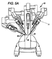
図5A及び5Bは、それぞれ、患者側カート54及び手術ツール62を示している。手術ツール62は、手術ツール26の一例である。図示の患者側カート22は、3つの手術ツール26及び処置部位の画像のキャプチャのために用いられる立体視内視鏡のような撮像デバイス28の操縦(manipulation)をもたらす。操縦は多数のロボット関節を有するロボット機構によってもたらされる。切開部の大きさを最小にするために、遠隔運動中心が切開部に維持されるように、撮像デバイス28及び手術ツール26を患者にある切開部を通じて位置付け且つ操縦し得る。手術ツール26が撮像デバイス28の視野内に位置付けられるとき、手術部位の画像は手術ツール26の遠位端の場像を含み得る。各ツール26は、それぞれの器具ホルダ31から取り外し可能であり且つそれぞれの器具ホルダ31によって支持され、それぞれのマニピュレータは、ロボット関節のうちの1つ又はそれよりも多くのロボット関節の遠位端に配置される。器具ホルダ31は、ロボット関節の動きを介して、患者側カート22に対してツール26の全体を動かすための、可動プラットフォームを提供する。手術マニピュレータ31は、1つ又はそれよりも多くの機械的及び/又は電気的インターフェースを用いてツール26を作動させる電力も提供する。そのようなキャリッジアセンブリの一例は、米国特許出願公開第2013/0325034号(代理人整理番号ISRG04330/US)に見出され、それを参照として援用する。
5A and 5B show the patient side cart 54 and the surgical tool 62, respectively. The surgical tool 62 is an example of the surgical tool 26. The illustrated patient-side cart 22 provides manipulation of three surgical tools 26 and an
図6は、遠隔手術的に制御される手術システム100の簡略化された概略図である。手術システム100は、例えば、外科医コンソール52であり得る、外科医コンソール102を含む。外科医コンソール102は、例えば、患者側カート22であり得る、患者側カート104を駆動させる。患者側カート104は、例えば、器具ホルダ31であり得る、器具ホルダ106を含む。
FIG. 6 is a simplified schematic diagram of a telesurgically controlled
器具ホルダ106は、2つの取り外し可能なプラットフォームを含み、第1のものはモータユニット108であり、第2のものはツール110である。モータユニット108は、5つのモータを保持するキャリッジアセンブリである。幾つかの実施態様では、5つだけのモータが用いられるのに対し、他の実施態様では、5つよりも多い又は少ないモータを用い得る。ここにおいて、モータユニット108は、異なる機構/構成部品に割り当てられ得る、複数のモータを含む。ここにおいて、モータユニット108は、伝動装置モータ112(transmission motor)と、シフターモータ114(shifter motor)と、ピッチモータ116と、ヨーモータ118と、低力把持モータ120とを含むが、これらのモータを、取り付けられる器具に依存する異なる目的のために用い得る。一般的に、各モータは、器具ホルダの対応する入力と機械的及び電気的に連結する電気モータである。
The instrument holder 106 comprises two removable platforms, the first being a motor unit 108 and the second being a tool 110. The motor unit 108 is a carriage assembly that holds five motors. In some embodiments, only five motors are used, while in other embodiments more or less than five motors may be used. Here, the motor unit 108 includes a plurality of motors that can be assigned to different mechanisms / components. Here, the motor unit 108 includes a transmission motor 112 (transmission motor), a shifter motor 114 (shifter motor), a
ツール110は、例えば、上述のツール26であり得る。ツール110として使用可能なツールの一例は、国際公開WO2011/060318(代理人整理番号:ISRG02360/PCT)にあり、それを参照として援用する。ここにおいて、ツール110は、3つの別個の入力を含む細長いエフェクタユニット122であり、各入力は、器具ホルダ106を経由して、ピッチモータ116、ヨーモータ118、及び低力把持モータ120と機械的に連結する。ツール110は、伝動装置モータ112及びシフターモータ114と機械的に連結する、伝動装置124(transmission)も含む。
Tool 110 may be, for example, tool 26 described above. An example of a tool that can be used as tool 110 is in International Publication WO 2011/060318 (Attorney Docket Number: ISRG 02360 / PCT), which is incorporated by reference. Here, the tool 110 is an elongated effector unit 122 that includes three separate inputs, each input mechanically via the instrument holder 106 with the
手術エンドエフェクタ126が、エフェクタユニット122の遠位端に配置される。手術エンドエフェクタ126及びエフェクタユニット122は、可動リスト(手首関節)を経由して接続される。そのようなリストの一例は、米国特許出願公開第US2011/0118709(代理人整理番号ISRG02350/US)に示されており、それをここに参照として援用する。平易な言い方をすれば、複数の別個の、しかしながら、相関する、構成部品によって、手術エンドエフェクタを特徴付けることができ、各構成部品は、手術エンドエフェクタ126のための自由度(DOF)をもたらす。ここにおいて用いるとき、DOFは、対応する動きをもたらすための、1つ又はそれよりも多くの相関する構成部品である。DOFsは、手術エンドエフェクタ126に、同時に又は別個に作動し得る異なる動作モードを与える。例えば、リストは、手術エンドエフェクタ126が、器具ホルダ106に対して縦揺れ(ピッチ)し且つ偏揺れ(ヨー)するのを可能にし、従って、ピッチDOF128及びヨーDOF130を含む。手術エンドエフェクタ126は、エンドエフェクタを細長い軸について回転させるロールDOF132も含む。
A surgical end effector 126 is disposed at the distal end of the effector unit 122. The surgical end effector 126 and the effector unit 122 are connected via a movable list (wrist joint). An example of such a list is shown in US Patent Application Publication No. US 2011/0118118709 (Attorney Docket Number ISRG 02350 / US), which is incorporated herein by reference. In simple terms, the surgical end effector can be characterized by a plurality of separate but correlated components, each component providing a degree of freedom (DOF) for the surgical end effector 126. As used herein, a DOF is one or more correlated components to provide a corresponding motion. The DOFs provide the surgical end effector 126 with different modes of operation that can be actuated simultaneously or separately. For example, the wrist allows the surgical end effector 126 to pitch and yaw relative to the tool holder 106, and thus includes a
手術エンドエフェクタ126は、手術ステープラ(stapler)のように、締付け及び切断機構を含んでよい。そのような締付け機構の一例は、2010年11月12日に出願された米国特許出願第12/945,541号(代理人整理番号ISRG02330/US)に示されており、それを参照として援用する。締付け機構は、2つのモードに従って把持することができ、従って、2つのDOFsを含む。組織を優しく操るために、低力DOF132(例えば、ケーブルで作動させられる機構)が、クランプを低力で動かす(toggle)ように動作する。低力DOF132は、切断又はステープル留め(stapling)作業のために手術エンドエフェクタを段階付ける(staging)のに有用である。例えば、切断又はステープル留め作業に備えて組織を止血するために、高力DOF134(例えば、親ネジで作動される機構)が、クランプを更に開き或いはクランプを比較的高い力で組織の上で閉じるように動作する。ひとたび締め付けられると、手術エンドエフェクタ126は、ツール作動DOF138を利用して、組織に更に影響を与える、例えば、ステープル留め、切断、及び/又は焼灼デバイス。
The surgical end effector 126 may include a clamping and cutting mechanism, as a surgical stapler. An example of such a tightening mechanism is shown in US patent application Ser. No. 12 / 945,541 filed on Nov. 12, 2010 (Attorney Docket No. ISRG02330 / US), which is incorporated by reference. . The clamping mechanism can be gripped according to two modes, thus including two DOFs. To gently manipulate tissue, a low force DOF 132 (e.g., a cable actuated mechanism) operates to toggle the clamp. Low strength DOF 132 is useful for staging surgical end effectors for cutting or stapling operations. For example, a high strength DOF 134 (e.g., a mechanism actuated by a lead screw) opens the clamp further or closes the clamp with relatively high force on the tissue to stop the tissue in preparation for cutting or stapling operations. To work. Once tightened, the surgical end effector 126 utilizes the tool actuated
図示のように、ピッチモータ116、ヨーモータ118、及び低力把持モータ120は、それぞれ、ピッチDOF128、ヨーDOF130、及び低力把持DOF139を駆動させる。従って、ピッチDOF128、ヨーDOF130、及び低力把持DOF139の各々は、モータと別個に対にされ、他のDOFsに対して独立的に且つ同時に作動し得る。
As shown, the
しかしながら、高力DOF126、ロールDOF132、及びツール作動DOF138は、伝動装置を介して、伝動装置モータ112と単一の入力を共用する。従って、高力DOF126、ロールDOF132、及びツール作動DOF138のうちの1つのみが、一度に作動し得る。何故ならば、伝動装置モータ112との連結は別個に起こるからである。シフターモータ114は、高力DOF126、ロールDOF132、及びツール作動DOF138の間で伝動装置モータ112の出力をシフトさせるように作動させられる。従って、伝動装置124は、各モータが単一のDOFに充てられる構成よりも大きな量のDOFsを有利に可能にする。
However, the high strength DOF 126, the roll DOF 132, and the tool actuated
II.例示的な伝動装置 II. Example gearing
本発明の実施態様は、モータキャリッジから許容される5つの入力を備えるステープラ機器の6つの自由度(6DOFs)を制御するシステム及び方法に関する。シフター(shifter)を用いるには5つの入力のうちの1つを要し、それは他の入力が3つの異なるステープラDOFsに選択的に係合させられるのを可能にする。ステープラ器具の6つのDOFは、リストロール、リストピッチ、リストヨー、低力把持(トグル(toggle))、高力把持(クランプ)、及びツール作動(ステープル発射(fire))を含み得る。リストピッチ、ヨー、及び低力把持は、ケーブルで作動させられてよいのに対し、ロール、クランプ、及び発射は、独立的なセットの同軸歯車によって駆動させられる。使用中、伝動装置は、3つの主要モード、即ち、ロール、クランプ/クランプ解除(unclamp)、及び発射を含み得る。リスト回転、ピッチ、ヨー、及び低力把持は、全て、サーボ制御の下にあり、高力把持及び発射DOFsは、ロール軸に連結される。 Embodiments of the present invention relate to systems and methods for controlling six degrees of freedom (6 DOFs) of a stapler instrument comprising five inputs allowed from a motor carriage. Using a shifter requires one of five inputs, which allows the other inputs to be selectively engaged with three different stapler DOFs. The six DOFs of the stapler device may include wrist roll, wrist pitch, wrist yaw, low force grips (toggles), high force grips (clamps), and tool actuation (staples fire). The wrist pitch, yaw and low force grips may be actuated with a cable, while the roll, clamp and launch are driven by an independent set of coaxial gears. In use, the transmission can include three major modes: roll, clamp / unclamp, and fire. The wrist rotation, pitch, yaw and low force grips are all under servo control, and high force grip and firing DOFs are coupled to the roll axis.
多くの実施態様において、被駆動入力は、リストロール、クランプ、及び/又は発射に選択的に連結される。これは適切なステープラDOFと係合し且つ係合が外れて回転させられ得る遊び歯車(idler gears)の使用を通じて行われる。加えて、レバーアームの使用を通じて各DOFを所定の位置に係止する方法がある。これらのレバーアームは、適切な数及び形状のローブ(lobes)を備えるカムシャフトであり得る、入力をシフトすることによって制御される。リストのロール移動中、クランプ及び発射リングがロール歯車と共に回転することが必要である。この制約の故に、器具入力と入力リングとロール歯車との間の歯車比は同じである。そのようにして、以下の状態の間、全てのリング/歯車は係合させられ、従って、一緒に回転するので、発射及び高力把持ドライブシャフトは、リストに対して回転しない。全ての移行は1つの機能ずつ動くに過ぎないようにシステムを構成し得る。このようにして、全ての移行は安全性のために検査可能である。追従(係合)することから移行するとき、ロール歯車は係止させられる。ロール歯車が係止アーム(locker arm)の歯と整列させられるように位置付けられることを必要とするリストの必要を回避するために、このDOFに二次的な摩擦係止がある。 In many embodiments, the driven input is selectively coupled to the wrist roll, clamp, and / or firing. This is done through the use of idler gears that can be engaged and disengaged from the appropriate stapler DOF. In addition, there is a way to lock each DOF in place through the use of a lever arm. These lever arms are controlled by shifting the input, which may be a camshaft with the appropriate number and shape of lobes. During roll movement of the wrist, it is necessary that the clamp and firing ring rotate with the roll gear. Because of this limitation, the gear ratios between the tool input and the input ring and the roll gear are the same. As such, during the following conditions, all rings / gears are engaged and therefore rotate together, so the firing and high strength gripping drive shafts do not rotate relative to the wrist. The system can be configured such that all transitions only move one function at a time. In this way, all migrations can be checked for safety. When transitioning from following (engaging), the roll gear is locked. This DOF has a secondary friction lock to avoid the need for a wrist that requires the roll gear to be positioned to be aligned with the teeth of the locker arm.
図7A及び7Bは、それぞれ、伝動装置アセンブリ140の長手方向断面図及び軸方向断面図を示している。伝動装置は、高力DOF126、ロールDOF132、及びツール作動DOF138の各々のために歯車列(ギアトレーン)(gear train)を含む。
7A and 7B show longitudinal and axial cross-sectional views, respectively, of
A.第1の歯車列 A. First gear train
図7Aに注目すると、第1の歯車列142が、伝動装置アセンブリ140の近位端に配置されている。第1の歯車裂142は、主シャフト144を軸方向に回転させることによって、ロールDOF132を駆動させる。主シャフト144は、制御ケーブルを手術エンドエフェクタ126まで経路制御するための軸方向通路146を含む。主シャフト144は、近位歯車148の外歯147を駆動させることによって、直接的に回転させられる。
Focusing on FIG. 7A, a
B.第2の歯車列 B. Second gear train
第2の歯車列150が、伝動装置アセンブリ140の中間部分で、第1の歯車列142に直ぐ隣接して配置されている。第2の歯車列150は、主シャフト144に対する中間シャフト152の回転によって、高力把持DOF126を駆動させる。中間シャフト152は、主シャフト144によって保持され、従って、主シャフト144と回転させられる。別の言い方をすれば、中間シャフト152の回転軸は、主シャフト144の回転軸について軌道を描いて回る。
A
中間シャフト152は、中間内歯車154に直接的に接続され、次に、中間内歯車54は、中間歯車156の内歯(この図には示されていない)によって駆動される。中間歯車156は、究極的には伝動装置モータ112によって、中間歯車156を直接的に駆動させる、外歯158も含む。中間歯車156の外歯158は、近位歯車148の外歯147と同一に構成される。従って、同時に駆動されるならば、同一の入力歯車であると想定すると、中間歯車156と近位歯車148との間の相対的な動きはなく、従って、中間シャフト152は、駆動されない。
The
主シャフト144の外側部分が、軸受によって中間歯車156を保持する。第2の歯車列150の第1の係合解除状態(切離し状態)(disengaged state)において、中間歯車156及び近位歯車148の両方が伝動装置モータ112と同期的に係合させられるとき、中間歯車156は、(以下に記載する遠位歯車166と共に)主シャフト144と同期的に回転するよう構成され得る。第1の係合解除状態において、中間歯車156の回転は、中間内歯車154の回転をもたらさない。何故ならば、中間歯車156は、主シャフト144に対して回転することが可能にされないからである。別の言い方をすれば、第1の係合解除状態において、中間歯車156は、主シャフトと係合し、よって、中間シャフト152を動かすために、主シャフトに対して非同期的に動き得ない。以下に更に議論するように、第2の歯車列150は、第2の係合解除状態を含み、第2係合解除状態において、中間歯車156は、伝動装置モータ112から物理的に係合解除され(切り離され)且つ物理的に係止され、それにより、中間内歯車154を回転し得ず、駆動させ得ない。
An outer portion of the
(伝動装置モータ112との)第2の歯車列150の係合状態において、近位歯車148及び主シャフト144は係止され、従って、回転し得ない。よって、中間内歯車154の回転軸は、主シャフト144の回転軸について軌道を描いて回り得ない。しかしながら、中間内歯車154は、その独自の回転軸について回転し得ない。従って、係合状態において、中間歯車144は、主シャフト144に対して回転し、それにより、究極的には伝動装置モータ112によって、中間内歯車154を駆動させる。
In the engaged state of the second gear train 150 (with the transmission motor 112), the
C.第3の歯車列 C. Third gear train
第3の歯車列160が、伝動装置アセンブリ140の遠位部分に配置され、大部分は第2の歯車列150と同様に構成される。第3の歯車列160は、主シャフト144に対する遠位シャフト162の回転によってツール作動DOF138を駆動させる。遠位シャフト162は、主シャフト144によって保持され、従って、主シャフト144と共に回転する。第2の歯車列のような一般的な方法において、遠位シャフト162の回転軸は、主シャフト144の回転軸について軌道を描いて回り得る。
A
遠位シャフト162は、遠位内歯車164に直接的に接続され、次に、遠位内歯車164は、遠位歯車166の内歯168(この図面には示されていない)によって駆動される。遠位歯車166は、究極的には伝動装置モータ112によって、遠位歯車166を直接的に駆動させる、外歯168も含む。遠位歯車162の外歯168は、近位歯車148の外歯147並びに中間歯車156の外歯158と同じ方法において構成される。従って、同期的に駆動されるとき、遠位歯車166、中間歯車156、及び近位歯車148の間には、相対的な動きがない。
The
主シャフト144の外側部分は、軸受によって遠位歯車166を保持する。第3の歯車列160の第1の係合解除状態において、遠位歯車166及び近位歯車148の両方が伝動装置モータ112と同期的に係合させられるとき、遠位歯車166は、(中間歯車156と共に)主シャフト144と共に同期的に回転するように構成され得る。第1の係合解除状態において、遠位歯車166の回転は、遠位内歯車164の回転をもたらさない。何故ならば、遠位歯車166は、主シャフト144に対して横揺れ(ロール)することが許容されないからである。別の言い方をすれば、第1の係合解除状態において、遠位歯車166は、主歯車144と係合し、よって、遠位シャフトを動かすために、主シャフト144に対して非同期的に動き得ない。以下に更に議論するように、第3の歯車列160は、第2の係合解除状態を含み、第2の係合解除状態において、遠位歯車166は、伝動装置モータ112から物理的に係合解除され且つ物理的に係止され、それにより、遠位内歯車164を回転させ得ず、駆動させ得ない、
The outer portion of the
(伝動装置モータ112との)第3の歯車列160の係合状態において、近位歯車148及び主シャフト144は係止され、従って、回転し得ない。このようにして、遠位内歯車164の回転軸は、主シャフト144の回転軸について軌道を描いて周り得ない。しかしながら、遠位内歯車164は、その独自の回転軸について回転し得る。従って、係合状態において、遠位歯車166は、主シャフト144に対して回転し、それにより、究極的には伝動装置モータ112によって、遠位内歯車164を駆動させる。
In the engaged state of the third gear train 160 (with the transmission motor 112), the
D.歯車列構造 D. Gear train structure
図7Bに注目すると、第2の歯車列150の代表的な断面が示されている。第1の歯車列142及び第3の歯車列160は同様に構成され、従って、以下の記述は同様に当て嵌まる。しかしながら、第1の歯車列142の近位歯車148は、図示のように、内歯及び内歯車を含まない。何故ならば、近位歯車148が主シャフト144を回転させるからである。
Focusing on FIG. 7B, a representative cross section of the
手術ツール110のより大きなハウジング170が、伝動装置アセンブリ140を保持する。伝動装置モータ112は、各々の歯車列のために共用される、第1の入力歯車172を駆動させる。第1の入力歯車172は、遊び歯車174と噛み合わせられ、次に、遊び歯車174は、中間歯車156と噛み合う第2の入力歯車176と噛み合う。第2の入力歯車176は、第1の入力歯車172について回転するアーム(図示せず)の上にある。図示するように、第2の入力歯車176は、トラック(軌道)の上向き部分に位置付けられ、それにより、中間歯車156と噛み合わせられる。第2の入力歯車176を中間歯車156から係合解除させるために、第2の入力歯車176を動かし得る。入力バネ176が第2の入力歯車176とハウジング170との間に装填されて、第2の入力歯車176を中間歯車156に対して付勢する。
The
カムシャフト180が、歯車列に沿って配置される。カムシャフト180は、一般的に、ドライブチェーン毎に2つのカムローブを含む。ローブは回転して、DOF機構を歯車列と係合させ且つ係合解除させる。
A
第1のカムローブ182は回転して、ロッカーアーム184(rocker arm)の表面183と係合する。ロッカーアーム184は、ロッカーピボット186について移動可能である。ロッカーアーム184は拡張して、ロッカーアームのフック付き部分185で、第2の入力歯車176と係合する。第1のカムローブ182の低い部分がロッカーアーム184と係合させられるとき、第2の入力歯車176は、図示のように、中間歯車156と係合させられる。
The
第1のカムローブ182の高い部分がロッカーアーム184の表面183と係合するとき、ロッカーアーム184は、ロッカーピボット186について下向きに動かされる。ロッカーアーム184及び第2の入力歯車シャフト176の係合の故に、この下向きの動きは、第2の入力歯車176を中間歯車156から係合解除させる。従って、第1のカムローブ182のこの位置において、第1の入力歯車に適用される動力は、中間歯車156に移転されない。
When the high portion of the
第2のカムローブ186が回転して、係止アーム188の表面187と係合し、係止アーム188は、係止アームピボット190について旋回する。係止アーム188は、歯付き部分192を含み、歯付き部分192は、歯付き部分192を中間歯車156と噛合させるよう動かされ得る。係止バネ194が、係止アーム188とハウジング170との間に装着されて、歯付き部分192を中間歯車156から離れる方向に付勢する。
The
第2のカムローブ186の低い部分が係止アーム188の表面187と係合するとき、歯付き部分192は、図示のように、中間歯車156から離れる方向に動かされる。従って、この位置において、中間歯車156は係止解除され(unlock)、回転することが可能にされる。
When the lower portion of the
ステープラが組織に対して締め付けられる間のシステム故障の場合には、手動のクランプ解除構成が提供される。幾つかの実施態様において、これは、以下に記載するように、使用者が手動でカムシャフト180を高力把持DOF状態まで回転させることによって、達成され得る。図7Cに示すように、回転可能であり、且つ究極的には中間シャフト152とインターフェース接続する一方向クラッチ194に接続される、連動フラッグ192(interlock flag)を動かすよう、連動カム190(interlock cam)が高い状態に移動可能である。クランプ状態で、連動フラッグ192は、ジョーがクランプ解除されるのを可能にするに過ぎない方向において一方向クラッチ194を介して中間シャフト152を駆動させるよう、使用者アクセスをもたらす。
In the event of a system failure while the stapler is clamped against tissue, a manual unclamping arrangement is provided. In some embodiments, this may be achieved by the user manually rotating the
III.伝動装置シフト方法(Transmission Shifting Method) III. Transmission Shifting Method
第2のカムローブ186の高い部分が係止アーム188の表面187と係合するとき、歯付き部分192が動かされて、中間歯車156と係合する。この位置は、中間歯車156を係止アーム188と係止させ、従って、中間歯車156は動き得ない。中間歯車156を係止する1つの目的は、高力把持DOFの最後の位置を係止状態に係止することである。一般的に、各歯車列は同様の方法において係止され、よって、望まれていない動きを防止する。
When the high portion of the
カムシャフト180は、歯車列を調和して作動させるように構成され、それは、カムシャフトタイミングを通じて達成される。図8は、伝動装置140の動作についてのカム状態表を示している。前に議論したように、歯車列は、共通のカムシャフトを共用し、それは、例えば、図7Bに示すカムシャフト180である。カムシャフト180は、各歯車列に少なくとも2つのローブを提供し、例えば、第1のカムローブ182及び第2のカムローブ186は、第2の歯車列と共に作動する。しかしながら、幾つかの歯車列は、より多くのローブを含み得る。例えば、幾つかの実施態様において、第1の歯車列は、摩擦係止を作動させる第3のローブを含む。そして、図7Cに示すように、システム故障の場合にDOFsをバックドライブ(back drive)させる安全機構として追加的なローブを含め得る。
The
一般的に、各歯車列のために、1つのカムローブが動力係合を制御するように動作可能であり、他のカムローブは歯車列を係止するように動作可能である。従って、各歯車列は、動力カム(power cam)及び係止カム(locker cam)によって作動させられる。平易な言い方をすれば、各カムは、低い状態と、高い状態とを有し、移行部が中間で傾斜する。各低い及び高い状態の持続時間は、持ち上げられる物体(例えば、係止アーム188及びロッカーアーム184)の動作の所望の持続時間に基づく。
Generally, for each gear train, one cam lobe is operable to control power engagement and the other cam lobe is operable to lock the gear train. Thus, each gear train is actuated by a power cam and a locker cam. In simple terms, each cam has a low state and a high state, and the transition slopes in the middle. The duration of each low and high state is based on the desired duration of movement of the object being lifted (e.g., locking
A.第1の伝動装置モードについてのカム状態 A. Cam state for the first transmission mode
カム状態表は、360度の回転に亘る、各カムについての低い状態及び高い状態を示している。0度及び360度の回転で、伝動装置140は、ロールDOF132の動作のための動力を供給するように構成される。図示するように、動力カムは、各歯車列について、高い状態にあり、係止カムは、各歯車列について、低い状態にある。従って、第1の歯車列142は、伝動装置モータ112と係止解除させられ且つ係合させられる。このようにして、第1の歯車列142の係止アームは、近位歯車148から係合解除され、第2の入力歯車は、近位歯車148と係合させられる。第2の歯車列150及び第3の歯車列160も係止解除され、中間歯車156及び遠位歯車166は伝動装置モータと接触したままである。
The cam status table shows the low and high states for each cam over 360 degrees of rotation. At 0 degrees and 360 degrees of rotation, the
上述のように、ロールDOF132の係合中、中間歯車156及び遠位歯車166は、近位歯車148と同期して回転することが求められる。何故ならば、中間内歯車154及び遠位内歯車164は、主シャフト144内に保持され、主シャフト144と共に回転するからである。このようにして、中間歯車156/中間内歯車154と遠位歯車166/遠位内歯車164との間の相対的な動きが回避され、それにより、中間シャフト152及び遠位シャフト162の動作を防止する。従って、中間歯車156及び遠位歯車166は、伝動装置モータ112と係合させられたままであり、よって、ロール動作の間に回転させられるが、第2の歯車列150及び第3の歯車列160は、それぞれのDOFsを作動させない。
As mentioned above, during engagement of the roll DOF 132, the
B.第2の伝動装置モードについてのカム状態 B. Cam state for the second transmission mode
カムシャフト180の約120度の回転で、伝動装置は、高力把持DOF136に動力を提供するように構成される。ここで、第1の歯車列142及び第3の歯車列160の動力カムは低い状態にあり、第2の歯車列150の動力カムは高い状態にある。このようにして、第1の歯車列142及び第3の歯車列160の第2の入力歯車は、それぞれ、近位歯車148及び遠位歯車166から係合解除させられるのに対し、第2の歯車列150の第2の入力歯車は、中間歯車156と係合させられる。よって、中間歯車156のみが伝動装置モータ112から動力を受ける。第1の歯車列142及び第3の歯車列160の係止カムは高い状態にあり、第2の歯車列150の動力カムは低い状態にある。このようにして、第1の歯車列142及び第3の歯車列160の係止アームは、それぞれ、近位歯車148及び遠位歯車166と係合させられるのに対し、第2の歯車列150の係止アームは、中間歯車156から係合解除させられる。加えて、図7Cを参照して上述したように、連動カムが高い状態に駆動させられる。これは、システム故障の場合に第2の歯車列を手動でバックドライブさせるよう、連動フラッグへの使用者アクセスを可能にする。
With approximately 120 degrees of rotation of the
C.第3の伝動装置モードについてのカム状態 C. Cam state for the third transmission mode
カムシャフト180の約240度の回転で、伝動装置は、ツール作動DOF138に動力を提供するようシフトされる。ここで、第1の歯車列142及び第2の歯車列150の動力カムは低い状態にあり、第3の歯車列160の動力カムは高い状態にある。このようにして、第1の歯車列142及び第2の歯車列150の第2の入力歯車は、それぞれ、近位歯車148及び中間歯車156から係合解除させられるのに対し、第3の歯車列160の第2の入力歯車は、遠位歯車166と係合させられる。よって、遠位歯車166のみが、伝動装置モータ112から動力を受ける。第1の歯車列142及び第2の歯車列150の係止カムは高い状態にあり、第3の歯車列160の係止カムは低い状態にある。このようにして、第1の歯車列142及び第2の歯車列150の係止アームは、それぞれ、近位歯車148及び中間歯車156と係合させられるのに対し、第3の歯車列160の係止アームは、遠位歯車166から係合解除させられる。よって、遠位歯車166のみが自由に回転する。
With approximately 240 degrees of rotation of the
図9は、伝動装置140の異なる動作モード、即ち、第1の歯車列142(ロールモード)、第2の歯車列150(把持モード)、及び第3の歯車列160(ツール作動モード)の間で出力をシフトすることの高レベル図を示している。各モードの間で、各特定のモード間シフトのために、シフトアルゴリズム(shifting algorithm)が特定される。幾つかの手術器具のために、モード間の移行は、器具の細長いシャフトのロール位置に関して重要であり得る。何故ならば、ロール位置は、手術器具全体の位置に影響を及ぼすからである。時折、ステープル器具伝動装置内の歯車にバックラッシュがある。時間の経過と共に、小さなバックラッシュに起因する動きは、ロール/クランプ/発射向き/位置をその基準地点からドリフト(漂流)させる。僅かなバックラッシュ運動を補償するために、初期ロール位置が歯車の1つの側面に対するように定められる。シフトアルゴリズムの部分として、歯車はこの位置に付勢される(動かされる)ので、ロール位置は歯車内のバックラッシュと一致する。これはシフト精度位置を向上させるのを助け、他の出力のためにも行われ得る。カムシャフト180は、これらの構成をアクティブ化する前に、ロール機能、把持機能、及びツール作動機能のための制動を管理しなければならない。幾つかの実施態様では、ソフトウェアがカム位置をモニタリングするのを可能にする、カムシャフト180と係合させられるロールエンコーダがあり、ロールモード、把持モード、及びツール作動モードは、カムがその正しい向きにあるものとして感知されるときに可能にされるだけである。グリップモードからロールモードへのシフトの一例が図10に示されている。しかしながら、この方法は比較的包括的(generic)であり、伝動装置140の他のモードの間のシフトにも適用可能である。
FIG. 9 shows the different operating modes of the
動作1002で、コントローラ(例えば、患者側カート104のプロセッサ)が、(例えば、外科医コンソール102から)命令を受信して、把持モード(伝動装置モータ112に対する第2の歯車列150の係合)からロールモード(伝動装置モータ112に対する第2の歯車列150の係合)にシフトさせる。故に、動作1004で、コントローラは、シフターモータ114にカムシャフト180を移動させ、それにより、近位歯車148を伝動装置モータ112と係合させる。この動作中、コントローラは、カムシャフト180が動くのを待ち、動きが完了したか、或いは、例えば歯車の歯の不整列の故に、停止したかを決定するために、周期的に確認する。動作が停止したことが決定されるならば、シフトは中止される。
At
コントローラが、近位歯車148が係止されたことを決定した後に、コントローラは、動作1006で、整列試験を行う。整列試験のために、近位歯車148は伝動装置モータ112を用いて係止アームに対して駆動させられて、近位歯車148及びカムシャフト180が適切に整列されたこと、即ち、所定の停止位置(park position)にあることを決定する。この動作において、伝動装置モータ112は、比較的低いトルクの下で近位歯車148の動きを停止させる試みにおいて、比較的低いトルクを用いて駆動させられる。動きが停止させられているならば、コントローラは、近位歯車148が適切に整列させられていることを決定する。動きが停止させられていない、即ち、停止せずに過剰に動くならば、コントローラは、近位歯車148が適切に整列させられていないことを決定し、シフトは中止される。
After the controller determines that the
コントローラが、近位歯車148が整列させられたことを決定した後に、コントローラは、動作1008で制動試験を行い、近位歯車148が、使用を許容する前に、適切に制動されているか否かを確認する。制動試験のために、近位歯車148は、比較的高いトルクを用いて係止アームに対して駆動させられて、伝動装置モータ112が、適用される荷重の下で、磁気的に飽和されるようになっているか否かを決定する。もしそうであるならば、これは近位歯車が適切に制動させられていることを示す。伝動装置モータ112がそのトルクの下で飽和させられていないならば、制動試験は停止され、シフトは中止される。
After the controller determines that the
動作1010で、コントローラは、シフターモータ114にカムシャフト180を移動させ、それにより、近位歯車148を係止解除する。この動作中、コントローラは、カムシャフト180が動くのを待ち、その動きが完了したか或いは停止したかを決定するために、周期的に確認する。動作が停止したことが決定されるならば、シフトは中止される。動作が停止していないならば、近位歯車148は係止解除され、動作1012で、使用可能にされる。幾つかの場合には、ロールモードが許可されても、シャフトをロールさせるのは望ましくない。故に、モータ112の出力を異なる歯車列にシフトすることができ、それは本質的に方法1000を繰り返す。
At
他の変形が本発明の精神内にある。よって、本発明は様々な変形及び代替的な構造の余地があるが、それらの特定の例示される実施態様が図面に示され、上で詳細に記載された。しかしながら、本発明を開示の特定の形態又は複数の形態に限定する意図はなく、逆に、本発明は、付属の請求項に定められるような、本発明の精神及び範囲内に入る、全ての変形、代替的な構造、及び均等物をカバーすることを意図することが理解されなければならない。 Other variations are within the spirit of the invention. Thus, while the invention is susceptible to various modifications and alternative constructions, certain illustrated embodiments thereof are shown in the drawings and have been described above in detail. However, there is no intention to limit the invention to the particular form or forms disclosed, and conversely, the invention falls within the spirit and scope of the invention as defined in the appended claims. It should be understood that it is intended to cover variations, alternative constructions, and equivalents.
不定冠詞及び定冠詞の使用並びに本発明を記載する文脈における(特に後続の請求項の文脈における)類似の言及は、ここにおいてその他のことが示されない限り或いは文脈が明らかに矛盾しない限り、単数及び複数の両方をカバーすることを意図する。「含む」(“comprising”)、「有する」(“having”)、「含む」(“including”)及び「包含する」(“containing”)という用語は、特段の断りのない限り、開放端の用語(即ち、「〜を含むが、〜に限定されない」を意味するもの)と解釈されるべきである。「接続され」(“connected”)という用語は、何か介在するものがあるとしても、部分的に又は全体的に、〜に収容され、〜に取り付けられ、或いは結合されるものと解釈されるべきである。ここにおける値の範囲の引用は、ここにおいてその他のことが示されない限り、その範囲内に入る各別個の値を個別に言及する略記的な方法としての機能を果たすことを意図するに過ぎず、各別個の値は、恰もそれがここで個別に引用されているかのように、本明細書中に組み込まれる。ここにおいてその他のことがしめされない限り或いは文脈が明らかに矛盾しない限り、ここに記載する全ての方法を任意の適切な順序で行い得る。ここにおいて提供される、ありとあらゆる実施例又は例示的な言葉(例えば、「のような」)の使用は、本発明の実施態様をより良好に例示することを意図するに過ぎず、その他のことが請求されない限り、本発明の範囲に対する限定を提示しない。本明細書中の如何なる言葉も、いずれかの請求されない要素が本発明の実施にとって本質的であることを示すように解釈されてならない。 The use of the indefinite article and the definite article, as well as similar references (in particular in the context of the claims that follow) in the context of describing the present invention refer to the singular and the plural unless the context otherwise expressly indicates otherwise. Intended to cover both. The terms "comprising", "having", "including" and "containing" are open-ended unless the context indicates otherwise. It should be interpreted as a term (i.e. meaning "including but not limited to"). The term "connected" is to be interpreted as partially or wholly housed, attached to, or coupled to, whatever, if anything It should. The recitation of ranges of values herein is only intended to serve as a shorthand method of referring individually to each separate value falling within the range, unless otherwise stated herein; Each distinct value is incorporated herein as if it were individually cited here. Unless otherwise stated herein or unless the context is clearly contradictory, all methods described herein may be performed in any suitable order. The use of any of the examples or exemplary words (eg, "like") provided herein is only intended to better illustrate the embodiments of the present invention and others. Unless claimed, no limitation to the scope of the invention is presented. No language in the specification should be construed as indicating any non-claimed element as essential to the practice of the invention.
本発明者が知る本発明を実施するための最良態様(ベストモード)を含む本発明の好適実施態様をここに記載する。前述の記述を判読した後に、それらの好適実施態様の変形が当業者に明らかになることがある。本発明者は当業者がそのような変形を適宜利用することを期待し、本発明者は本発明がここに具体的に記載する以外に実施されることを意図する。従って、この発明は、準拠法によって許容されるような、ここに添付する請求項中に引用される主題の全ての変形及び均等物を含む。その上、ここにおいてその他のことが示されない限り或いは文脈が明らかに矛盾しない限り、本発明は上述の要素のあらゆる組み合わせをその全ての可能な変形において包含する。 Preferred embodiments of the invention are described herein, including the best mode (best mode) for practicing the invention that the inventor knows. After reading the above description, variations of those preferred embodiments may become apparent to those skilled in the art. The inventors expect skilled artisans to utilize such variations as appropriate, and the inventors intend for the invention to be practiced other than as specifically described herein. Accordingly, this invention includes all modifications and equivalents of the subject matter recited in the claims appended hereto as permitted by applicable law. Moreover, the present invention includes all combinations of the above-described elements in all possible variations thereof, unless otherwise indicated herein or unless the context is clearly contradictory.
ここに引用する刊行物、特許出願、及び特許を含む、全ての参考文献は、あたかも各参考文献が参照として援用されることが個別に且つ具体的に示され且つその全文がここに示されているのかのように同じ程度に、ここに参照として援用される。 All references, including publications, patent applications, and patents cited herein, are individually and specifically indicated that each reference is incorporated by reference and the full text thereof is hereby incorporated by reference. To the same extent as if they were.
Claims (8)
前記伝動装置を制御する少なくとも1つのプロセッサを含むコントローラとを含み、
前記コントローラは、
前記第2のエフェクタドライブトレーンの出力歯車を係止するステップと、
前記モータの連結を前記第1のエフェクタドライブトレーンから前記第2のエフェクタドライブトレーンにシフトさせるステップと、
第1のトルクを用いて、前記係止された出力歯車を駆動させることによって、前記出力歯車が整列させられていることを決定するステップと、
第2のトルクを用いて、前記係止された出力歯車を駆動させることによって、前記出力歯車が適切に制動させられていることを決定するステップと、
前記出力歯車を係止解除するステップと、
前記モータを用いて、前記第2のエフェクタドライブトレーンを駆動させるステップとを含む、
方法を行うように構成される、
手術システム。 A patient cart comprising a device to be operated remotely surgery type, the remote surgery vessels instrument that will be operated in expression may include a transmission device, and a surgical end effector having a plurality of end effectors component, the transmission A patient-side cart driven by a motor, said transmission comprising at least a first effector drive train and a second effector drive train;
A controller including at least one processor for controlling the transmission device;
The controller
A step of locking the output gear of the second et Fekuta drive train,
Shifting the connection of the motor from the first effector drive train to the second effector drive train;
Determining that the output gear is aligned by driving the locked output gear using a first torque;
Determining that the output gear is properly braked by driving the locked output gear with a second torque;
Unlocking the output gear;
Driving the second effector drive train using the motor.
Configured to do the way,
Surgery system.
請求項1に記載の手術システム。 Determining that the output gear is aligned includes determining that movement of the output gear is at rest under the first torque.
The surgical system according to claim 1.
Applications Claiming Priority (3)
| Application Number | Priority Date | Filing Date | Title |
|---|---|---|---|
| US201461973822P | 2014-04-01 | 2014-04-01 | |
| US61/973,822 | 2014-04-01 | ||
| PCT/US2015/023629 WO2015153636A1 (en) | 2014-04-01 | 2015-03-31 | Control input accuracy for teleoperated surgical instrument |
Related Child Applications (1)
| Application Number | Title | Priority Date | Filing Date |
|---|---|---|---|
| JP2019087818A Division JP6851419B2 (en) | 2014-04-01 | 2019-05-07 | Control input accuracy for remotely controlled surgical instruments |
Publications (3)
| Publication Number | Publication Date |
|---|---|
| JP2017515538A JP2017515538A (en) | 2017-06-15 |
| JP2017515538A5 JP2017515538A5 (en) | 2018-04-26 |
| JP6526047B2 true JP6526047B2 (en) | 2019-06-05 |
Family
ID=54241222
Family Applications (2)
| Application Number | Title | Priority Date | Filing Date |
|---|---|---|---|
| JP2016560592A Active JP6526047B2 (en) | 2014-04-01 | 2015-03-31 | Control input accuracy for remotely operated surgical instruments |
| JP2019087818A Active JP6851419B2 (en) | 2014-04-01 | 2019-05-07 | Control input accuracy for remotely controlled surgical instruments |
Family Applications After (1)
| Application Number | Title | Priority Date | Filing Date |
|---|---|---|---|
| JP2019087818A Active JP6851419B2 (en) | 2014-04-01 | 2019-05-07 | Control input accuracy for remotely controlled surgical instruments |
Country Status (6)
| Country | Link |
|---|---|
| US (3) | US10098705B2 (en) |
| EP (2) | EP3492036B1 (en) |
| JP (2) | JP6526047B2 (en) |
| KR (2) | KR102399312B1 (en) |
| CN (2) | CN110215280B (en) |
| WO (1) | WO2015153636A1 (en) |
Families Citing this family (128)
| Publication number | Priority date | Publication date | Assignee | Title |
|---|---|---|---|---|
| US11871901B2 (en) | 2012-05-20 | 2024-01-16 | Cilag Gmbh International | Method for situational awareness for surgical network or surgical network connected device capable of adjusting function based on a sensed situation or usage |
| WO2015153636A1 (en) | 2014-04-01 | 2015-10-08 | Intuitive Surgical Operations, Inc. | Control input accuracy for teleoperated surgical instrument |
| US11504192B2 (en) | 2014-10-30 | 2022-11-22 | Cilag Gmbh International | Method of hub communication with surgical instrument systems |
| US10420552B2 (en) * | 2016-04-01 | 2019-09-24 | Ethicon Llc | Surgical stapling system configured to provide selective cutting of tissue |
| US10591032B2 (en) | 2016-09-15 | 2020-03-17 | Intuitive Surgical Operations, Inc. | Split nut drive |
| WO2018052810A1 (en) | 2016-09-15 | 2018-03-22 | Intuitive Surgical Operations, Inc. | Medical device drive system |
| WO2018052806A1 (en) * | 2016-09-15 | 2018-03-22 | Intuitive Surgical Operations, Inc. | Medical device drive system |
| US11911045B2 (en) | 2017-10-30 | 2024-02-27 | Cllag GmbH International | Method for operating a powered articulating multi-clip applier |
| US11801098B2 (en) | 2017-10-30 | 2023-10-31 | Cilag Gmbh International | Method of hub communication with surgical instrument systems |
| US11141160B2 (en) | 2017-10-30 | 2021-10-12 | Cilag Gmbh International | Clip applier comprising a motor controller |
| US11311342B2 (en) | 2017-10-30 | 2022-04-26 | Cilag Gmbh International | Method for communicating with surgical instrument systems |
| US11317919B2 (en) | 2017-10-30 | 2022-05-03 | Cilag Gmbh International | Clip applier comprising a clip crimping system |
| US11925373B2 (en) | 2017-10-30 | 2024-03-12 | Cilag Gmbh International | Surgical suturing instrument comprising a non-circular needle |
| US11510741B2 (en) | 2017-10-30 | 2022-11-29 | Cilag Gmbh International | Method for producing a surgical instrument comprising a smart electrical system |
| US11291510B2 (en) | 2017-10-30 | 2022-04-05 | Cilag Gmbh International | Method of hub communication with surgical instrument systems |
| US11229436B2 (en) | 2017-10-30 | 2022-01-25 | Cilag Gmbh International | Surgical system comprising a surgical tool and a surgical hub |
| US11564756B2 (en) | 2017-10-30 | 2023-01-31 | Cilag Gmbh International | Method of hub communication with surgical instrument systems |
| US11147607B2 (en) | 2017-12-28 | 2021-10-19 | Cilag Gmbh International | Bipolar combination device that automatically adjusts pressure based on energy modality |
| US11786251B2 (en) | 2017-12-28 | 2023-10-17 | Cilag Gmbh International | Method for adaptive control schemes for surgical network control and interaction |
| US11844579B2 (en) | 2017-12-28 | 2023-12-19 | Cilag Gmbh International | Adjustments based on airborne particle properties |
| US11304763B2 (en) | 2017-12-28 | 2022-04-19 | Cilag Gmbh International | Image capturing of the areas outside the abdomen to improve placement and control of a surgical device in use |
| US11160605B2 (en) | 2017-12-28 | 2021-11-02 | Cilag Gmbh International | Surgical evacuation sensing and motor control |
| US11234756B2 (en) | 2017-12-28 | 2022-02-01 | Cilag Gmbh International | Powered surgical tool with predefined adjustable control algorithm for controlling end effector parameter |
| US11612408B2 (en) | 2017-12-28 | 2023-03-28 | Cilag Gmbh International | Determining tissue composition via an ultrasonic system |
| US11266468B2 (en) | 2017-12-28 | 2022-03-08 | Cilag Gmbh International | Cooperative utilization of data derived from secondary sources by intelligent surgical hubs |
| US11659023B2 (en) | 2017-12-28 | 2023-05-23 | Cilag Gmbh International | Method of hub communication |
| US11896443B2 (en) | 2017-12-28 | 2024-02-13 | Cilag Gmbh International | Control of a surgical system through a surgical barrier |
| US11069012B2 (en) | 2017-12-28 | 2021-07-20 | Cilag Gmbh International | Interactive surgical systems with condition handling of devices and data capabilities |
| US11696760B2 (en) | 2017-12-28 | 2023-07-11 | Cilag Gmbh International | Safety systems for smart powered surgical stapling |
| US11744604B2 (en) | 2017-12-28 | 2023-09-05 | Cilag Gmbh International | Surgical instrument with a hardware-only control circuit |
| US11410259B2 (en) | 2017-12-28 | 2022-08-09 | Cilag Gmbh International | Adaptive control program updates for surgical devices |
| US11464535B2 (en) | 2017-12-28 | 2022-10-11 | Cilag Gmbh International | Detection of end effector emersion in liquid |
| US10695081B2 (en) | 2017-12-28 | 2020-06-30 | Ethicon Llc | Controlling a surgical instrument according to sensed closure parameters |
| US11376002B2 (en) | 2017-12-28 | 2022-07-05 | Cilag Gmbh International | Surgical instrument cartridge sensor assemblies |
| US11324557B2 (en) | 2017-12-28 | 2022-05-10 | Cilag Gmbh International | Surgical instrument with a sensing array |
| US11633237B2 (en) | 2017-12-28 | 2023-04-25 | Cilag Gmbh International | Usage and technique analysis of surgeon / staff performance against a baseline to optimize device utilization and performance for both current and future procedures |
| US11464559B2 (en) | 2017-12-28 | 2022-10-11 | Cilag Gmbh International | Estimating state of ultrasonic end effector and control system therefor |
| US11166772B2 (en) | 2017-12-28 | 2021-11-09 | Cilag Gmbh International | Surgical hub coordination of control and communication of operating room devices |
| US11857152B2 (en) | 2017-12-28 | 2024-01-02 | Cilag Gmbh International | Surgical hub spatial awareness to determine devices in operating theater |
| US11419630B2 (en) | 2017-12-28 | 2022-08-23 | Cilag Gmbh International | Surgical system distributed processing |
| US11832899B2 (en) | 2017-12-28 | 2023-12-05 | Cilag Gmbh International | Surgical systems with autonomously adjustable control programs |
| US11253315B2 (en) | 2017-12-28 | 2022-02-22 | Cilag Gmbh International | Increasing radio frequency to create pad-less monopolar loop |
| US11864728B2 (en) | 2017-12-28 | 2024-01-09 | Cilag Gmbh International | Characterization of tissue irregularities through the use of mono-chromatic light refractivity |
| US11903601B2 (en) * | 2017-12-28 | 2024-02-20 | Cilag Gmbh International | Surgical instrument comprising a plurality of drive systems |
| US20190201039A1 (en) | 2017-12-28 | 2019-07-04 | Ethicon Llc | Situational awareness of electrosurgical systems |
| US10892995B2 (en) | 2017-12-28 | 2021-01-12 | Ethicon Llc | Surgical network determination of prioritization of communication, interaction, or processing based on system or device needs |
| US11056244B2 (en) | 2017-12-28 | 2021-07-06 | Cilag Gmbh International | Automated data scaling, alignment, and organizing based on predefined parameters within surgical networks |
| US11311306B2 (en) | 2017-12-28 | 2022-04-26 | Cilag Gmbh International | Surgical systems for detecting end effector tissue distribution irregularities |
| US11058498B2 (en) | 2017-12-28 | 2021-07-13 | Cilag Gmbh International | Cooperative surgical actions for robot-assisted surgical platforms |
| US11446052B2 (en) | 2017-12-28 | 2022-09-20 | Cilag Gmbh International | Variation of radio frequency and ultrasonic power level in cooperation with varying clamp arm pressure to achieve predefined heat flux or power applied to tissue |
| US11423007B2 (en) | 2017-12-28 | 2022-08-23 | Cilag Gmbh International | Adjustment of device control programs based on stratified contextual data in addition to the data |
| US11559307B2 (en) | 2017-12-28 | 2023-01-24 | Cilag Gmbh International | Method of robotic hub communication, detection, and control |
| US10966791B2 (en) | 2017-12-28 | 2021-04-06 | Ethicon Llc | Cloud-based medical analytics for medical facility segmented individualization of instrument function |
| US11179208B2 (en) | 2017-12-28 | 2021-11-23 | Cilag Gmbh International | Cloud-based medical analytics for security and authentication trends and reactive measures |
| US10755813B2 (en) | 2017-12-28 | 2020-08-25 | Ethicon Llc | Communication of smoke evacuation system parameters to hub or cloud in smoke evacuation module for interactive surgical platform |
| US11666331B2 (en) | 2017-12-28 | 2023-06-06 | Cilag Gmbh International | Systems for detecting proximity of surgical end effector to cancerous tissue |
| US11786245B2 (en) | 2017-12-28 | 2023-10-17 | Cilag Gmbh International | Surgical systems with prioritized data transmission capabilities |
| US11818052B2 (en) | 2017-12-28 | 2023-11-14 | Cilag Gmbh International | Surgical network determination of prioritization of communication, interaction, or processing based on system or device needs |
| US11424027B2 (en) | 2017-12-28 | 2022-08-23 | Cilag Gmbh International | Method for operating surgical instrument systems |
| US11678881B2 (en) | 2017-12-28 | 2023-06-20 | Cilag Gmbh International | Spatial awareness of surgical hubs in operating rooms |
| US10943454B2 (en) | 2017-12-28 | 2021-03-09 | Ethicon Llc | Detection and escalation of security responses of surgical instruments to increasing severity threats |
| US11364075B2 (en) | 2017-12-28 | 2022-06-21 | Cilag Gmbh International | Radio frequency energy device for delivering combined electrical signals |
| US11419667B2 (en) | 2017-12-28 | 2022-08-23 | Cilag Gmbh International | Ultrasonic energy device which varies pressure applied by clamp arm to provide threshold control pressure at a cut progression location |
| US11096693B2 (en) | 2017-12-28 | 2021-08-24 | Cilag Gmbh International | Adjustment of staple height of at least one row of staples based on the sensed tissue thickness or force in closing |
| US10758310B2 (en) | 2017-12-28 | 2020-09-01 | Ethicon Llc | Wireless pairing of a surgical device with another device within a sterile surgical field based on the usage and situational awareness of devices |
| US10849697B2 (en) | 2017-12-28 | 2020-12-01 | Ethicon Llc | Cloud interface for coupled surgical devices |
| US11109866B2 (en) | 2017-12-28 | 2021-09-07 | Cilag Gmbh International | Method for circular stapler control algorithm adjustment based on situational awareness |
| US11571234B2 (en) | 2017-12-28 | 2023-02-07 | Cilag Gmbh International | Temperature control of ultrasonic end effector and control system therefor |
| US11896322B2 (en) | 2017-12-28 | 2024-02-13 | Cilag Gmbh International | Sensing the patient position and contact utilizing the mono-polar return pad electrode to provide situational awareness to the hub |
| US11100631B2 (en) | 2017-12-28 | 2021-08-24 | Cilag Gmbh International | Use of laser light and red-green-blue coloration to determine properties of back scattered light |
| US20190201139A1 (en) | 2017-12-28 | 2019-07-04 | Ethicon Llc | Communication arrangements for robot-assisted surgical platforms |
| US11432885B2 (en) | 2017-12-28 | 2022-09-06 | Cilag Gmbh International | Sensing arrangements for robot-assisted surgical platforms |
| US11672605B2 (en) | 2017-12-28 | 2023-06-13 | Cilag Gmbh International | Sterile field interactive control displays |
| US11540855B2 (en) | 2017-12-28 | 2023-01-03 | Cilag Gmbh International | Controlling activation of an ultrasonic surgical instrument according to the presence of tissue |
| US10892899B2 (en) | 2017-12-28 | 2021-01-12 | Ethicon Llc | Self describing data packets generated at an issuing instrument |
| US11202570B2 (en) | 2017-12-28 | 2021-12-21 | Cilag Gmbh International | Communication hub and storage device for storing parameters and status of a surgical device to be shared with cloud based analytics systems |
| US11969142B2 (en) | 2017-12-28 | 2024-04-30 | Cilag Gmbh International | Method of compressing tissue within a stapling device and simultaneously displaying the location of the tissue within the jaws |
| US11132462B2 (en) | 2017-12-28 | 2021-09-28 | Cilag Gmbh International | Data stripping method to interrogate patient records and create anonymized record |
| US11278281B2 (en) | 2017-12-28 | 2022-03-22 | Cilag Gmbh International | Interactive surgical system |
| US11317937B2 (en) | 2018-03-08 | 2022-05-03 | Cilag Gmbh International | Determining the state of an ultrasonic end effector |
| US11602393B2 (en) | 2017-12-28 | 2023-03-14 | Cilag Gmbh International | Surgical evacuation sensing and generator control |
| US11284936B2 (en) | 2017-12-28 | 2022-03-29 | Cilag Gmbh International | Surgical instrument having a flexible electrode |
| US11389164B2 (en) | 2017-12-28 | 2022-07-19 | Cilag Gmbh International | Method of using reinforced flexible circuits with multiple sensors to optimize performance of radio frequency devices |
| US10944728B2 (en) | 2017-12-28 | 2021-03-09 | Ethicon Llc | Interactive surgical systems with encrypted communication capabilities |
| US11051876B2 (en) | 2017-12-28 | 2021-07-06 | Cilag Gmbh International | Surgical evacuation flow paths |
| US11832840B2 (en) | 2017-12-28 | 2023-12-05 | Cilag Gmbh International | Surgical instrument having a flexible circuit |
| US11576677B2 (en) | 2017-12-28 | 2023-02-14 | Cilag Gmbh International | Method of hub communication, processing, display, and cloud analytics |
| US11529187B2 (en) | 2017-12-28 | 2022-12-20 | Cilag Gmbh International | Surgical evacuation sensor arrangements |
| US11969216B2 (en) | 2017-12-28 | 2024-04-30 | Cilag Gmbh International | Surgical network recommendations from real time analysis of procedure variables against a baseline highlighting differences from the optimal solution |
| US11045591B2 (en) | 2017-12-28 | 2021-06-29 | Cilag Gmbh International | Dual in-series large and small droplet filters |
| US11076921B2 (en) | 2017-12-28 | 2021-08-03 | Cilag Gmbh International | Adaptive control program updates for surgical hubs |
| US11304699B2 (en) | 2017-12-28 | 2022-04-19 | Cilag Gmbh International | Method for adaptive control schemes for surgical network control and interaction |
| US11308075B2 (en) | 2017-12-28 | 2022-04-19 | Cilag Gmbh International | Surgical network, instrument, and cloud responses based on validation of received dataset and authentication of its source and integrity |
| US11304745B2 (en) | 2017-12-28 | 2022-04-19 | Cilag Gmbh International | Surgical evacuation sensing and display |
| US11273001B2 (en) | 2017-12-28 | 2022-03-15 | Cilag Gmbh International | Surgical hub and modular device response adjustment based on situational awareness |
| US11304720B2 (en) | 2017-12-28 | 2022-04-19 | Cilag Gmbh International | Activation of energy devices |
| US10987178B2 (en) | 2017-12-28 | 2021-04-27 | Ethicon Llc | Surgical hub control arrangements |
| US11589888B2 (en) | 2017-12-28 | 2023-02-28 | Cilag Gmbh International | Method for controlling smart energy devices |
| US11257589B2 (en) | 2017-12-28 | 2022-02-22 | Cilag Gmbh International | Real-time analysis of comprehensive cost of all instrumentation used in surgery utilizing data fluidity to track instruments through stocking and in-house processes |
| US10932872B2 (en) | 2017-12-28 | 2021-03-02 | Ethicon Llc | Cloud-based medical analytics for linking of local usage trends with the resource acquisition behaviors of larger data set |
| US11291495B2 (en) | 2017-12-28 | 2022-04-05 | Cilag Gmbh International | Interruption of energy due to inadvertent capacitive coupling |
| US11559308B2 (en) | 2017-12-28 | 2023-01-24 | Cilag Gmbh International | Method for smart energy device infrastructure |
| US11937769B2 (en) | 2017-12-28 | 2024-03-26 | Cilag Gmbh International | Method of hub communication, processing, storage and display |
| US11259830B2 (en) | 2018-03-08 | 2022-03-01 | Cilag Gmbh International | Methods for controlling temperature in ultrasonic device |
| US11337746B2 (en) | 2018-03-08 | 2022-05-24 | Cilag Gmbh International | Smart blade and power pulsing |
| US11389188B2 (en) | 2018-03-08 | 2022-07-19 | Cilag Gmbh International | Start temperature of blade |
| US11096688B2 (en) | 2018-03-28 | 2021-08-24 | Cilag Gmbh International | Rotary driven firing members with different anvil and channel engagement features |
| US11129611B2 (en) | 2018-03-28 | 2021-09-28 | Cilag Gmbh International | Surgical staplers with arrangements for maintaining a firing member thereof in a locked configuration unless a compatible cartridge has been installed therein |
| US11278280B2 (en) | 2018-03-28 | 2022-03-22 | Cilag Gmbh International | Surgical instrument comprising a jaw closure lockout |
| US11219453B2 (en) | 2018-03-28 | 2022-01-11 | Cilag Gmbh International | Surgical stapling devices with cartridge compatible closure and firing lockout arrangements |
| US11090047B2 (en) | 2018-03-28 | 2021-08-17 | Cilag Gmbh International | Surgical instrument comprising an adaptive control system |
| US10973520B2 (en) | 2018-03-28 | 2021-04-13 | Ethicon Llc | Surgical staple cartridge with firing member driven camming assembly that has an onboard tissue cutting feature |
| US11471156B2 (en) | 2018-03-28 | 2022-10-18 | Cilag Gmbh International | Surgical stapling devices with improved rotary driven closure systems |
| US11589865B2 (en) | 2018-03-28 | 2023-02-28 | Cilag Gmbh International | Methods for controlling a powered surgical stapler that has separate rotary closure and firing systems |
| US11207067B2 (en) | 2018-03-28 | 2021-12-28 | Cilag Gmbh International | Surgical stapling device with separate rotary driven closure and firing systems and firing member that engages both jaws while firing |
| US11071441B2 (en) | 2018-04-20 | 2021-07-27 | Verb Surgical Inc. | Surgical robotic tool multi-motor actuator and controller |
| CA3121914A1 (en) * | 2018-12-06 | 2020-06-11 | Covidien Lp | Method of controlling cable driven end effectors |
| US11317915B2 (en) | 2019-02-19 | 2022-05-03 | Cilag Gmbh International | Universal cartridge based key feature that unlocks multiple lockout arrangements in different surgical staplers |
| US11369377B2 (en) | 2019-02-19 | 2022-06-28 | Cilag Gmbh International | Surgical stapling assembly with cartridge based retainer configured to unlock a firing lockout |
| US11751872B2 (en) | 2019-02-19 | 2023-09-12 | Cilag Gmbh International | Insertable deactivator element for surgical stapler lockouts |
| US11357503B2 (en) | 2019-02-19 | 2022-06-14 | Cilag Gmbh International | Staple cartridge retainers with frangible retention features and methods of using same |
| US11331101B2 (en) | 2019-02-19 | 2022-05-17 | Cilag Gmbh International | Deactivator element for defeating surgical stapling device lockouts |
| USD952144S1 (en) | 2019-06-25 | 2022-05-17 | Cilag Gmbh International | Surgical staple cartridge retainer with firing system authentication key |
| USD950728S1 (en) | 2019-06-25 | 2022-05-03 | Cilag Gmbh International | Surgical staple cartridge |
| USD964564S1 (en) | 2019-06-25 | 2022-09-20 | Cilag Gmbh International | Surgical staple cartridge retainer with a closure system authentication key |
| US11877818B2 (en) * | 2020-06-26 | 2024-01-23 | Procept Biorobotics Corporation | Integration of robotic arms with surgical probes |
| CN113180831A (en) * | 2021-04-16 | 2021-07-30 | 南京航空航天大学 | Magnetic anchoring laparoscopic surgery robot |
| US20230100698A1 (en) | 2021-09-29 | 2023-03-30 | Cilag Gmbh International | Methods for Controlling Cooperative Surgical Instruments |
Family Cites Families (39)
| Publication number | Priority date | Publication date | Assignee | Title |
|---|---|---|---|---|
| JPS62292945A (en) * | 1986-06-13 | 1987-12-19 | Nhk Spring Co Ltd | Rotary transmission lock device |
| US5279309A (en) | 1991-06-13 | 1994-01-18 | International Business Machines Corporation | Signaling device and method for monitoring positions in a surgical operation |
| US5184601A (en) | 1991-08-05 | 1993-02-09 | Putman John M | Endoscope stabilizer |
| ATE215430T1 (en) | 1992-01-21 | 2002-04-15 | Stanford Res Inst Int | ENDOSCOPIC SURGICAL INSTRUMENT |
| US6406472B1 (en) | 1993-05-14 | 2002-06-18 | Sri International, Inc. | Remote center positioner |
| EP0699053B1 (en) | 1993-05-14 | 1999-03-17 | Sri International | Surgical apparatus |
| US5814038A (en) * | 1995-06-07 | 1998-09-29 | Sri International | Surgical manipulator for a telerobotic system |
| US5855583A (en) | 1996-02-20 | 1999-01-05 | Computer Motion, Inc. | Method and apparatus for performing minimally invasive cardiac procedures |
| DE19729178A1 (en) * | 1997-07-08 | 1999-01-14 | Kaltenbach & Voigt | Medical treatment device |
| WO2000007503A1 (en) | 1998-08-04 | 2000-02-17 | Intuitive Surgical, Inc. | Manipulator positioning linkage for robotic surgery |
| US6788018B1 (en) | 1999-08-03 | 2004-09-07 | Intuitive Surgical, Inc. | Ceiling and floor mounted surgical robot set-up arms |
| US7594912B2 (en) | 2004-09-30 | 2009-09-29 | Intuitive Surgical, Inc. | Offset remote center manipulator for robotic surgery |
| US6702805B1 (en) | 1999-11-12 | 2004-03-09 | Microdexterity Systems, Inc. | Manipulator |
| EP1351619A4 (en) | 2001-01-16 | 2011-01-05 | Microdexterity Systems Inc | Surgical manipulator |
| US7850642B2 (en) * | 2004-03-05 | 2010-12-14 | Hansen Medical, Inc. | Methods using a robotic catheter system |
| US7763015B2 (en) | 2005-01-24 | 2010-07-27 | Intuitive Surgical Operations, Inc. | Modular manipulator support for robotic surgery |
| JP2006321027A (en) * | 2005-05-20 | 2006-11-30 | Hitachi Ltd | Master slave type manipulator system and its operation input device |
| US8992422B2 (en) * | 2006-03-23 | 2015-03-31 | Ethicon Endo-Surgery, Inc. | Robotically-controlled endoscopic accessory channel |
| US8784435B2 (en) | 2006-06-13 | 2014-07-22 | Intuitive Surgical Operations, Inc. | Surgical system entry guide |
| US8231610B2 (en) * | 2006-09-06 | 2012-07-31 | National Cancer Center | Robotic surgical system for laparoscopic surgery |
| US8931682B2 (en) * | 2007-06-04 | 2015-01-13 | Ethicon Endo-Surgery, Inc. | Robotically-controlled shaft based rotary drive systems for surgical instruments |
| US8620473B2 (en) | 2007-06-13 | 2013-12-31 | Intuitive Surgical Operations, Inc. | Medical robotic system with coupled control modes |
| CA2698571C (en) | 2007-09-21 | 2016-12-20 | Power Medical Interventions, Llc | Surgical device |
| EP2498710B1 (en) | 2009-11-13 | 2018-05-16 | Intuitive Surgical Operations, Inc. | Motor interface for parallel drive shafts within an independently rotating member |
| CN108158649B (en) | 2009-11-13 | 2021-11-12 | 直观外科手术操作公司 | Surgical tool with compact wrist |
| KR101764780B1 (en) | 2009-11-13 | 2017-08-03 | 인튜어티브 서지컬 오퍼레이션즈 인코포레이티드 | End effector with redundant closing mechanisms |
| JP4888573B2 (en) * | 2010-01-28 | 2012-02-29 | ブラザー工業株式会社 | Image forming apparatus |
| CN101791233B (en) * | 2010-04-07 | 2011-04-13 | 上海交通大学 | Force feedback based remote control surgical device |
| JP5636234B2 (en) * | 2010-09-17 | 2014-12-03 | カール シュトルツ ゲゼルシャフト ミット ベシュレンクテル ハフツング ウント コンパニー コマンディートゲゼルシャフト | Medical manipulator |
| CN105748152B (en) | 2010-11-15 | 2018-06-26 | 直观外科手术操作公司 | Instrument shaft rolling is decoupled in operation instrument and end effector actuates |
| WO2012166817A2 (en) * | 2011-05-31 | 2012-12-06 | Intuitive Surgical Operations, Inc. | Surgical instrument with single drive input for two end effector mechanisms |
| JP6038901B2 (en) * | 2011-05-31 | 2016-12-07 | インテュイティブ サージカル オペレーションズ, インコーポレイテッド | Surgical instrument having control for detected fault condition |
| KR102184969B1 (en) | 2012-06-01 | 2020-12-01 | 인튜어티브 서지컬 오퍼레이션즈 인코포레이티드 | Instrument carriage assembly for surgical system |
| US9072536B2 (en) * | 2012-06-28 | 2015-07-07 | Ethicon Endo-Surgery, Inc. | Differential locking arrangements for rotary powered surgical instruments |
| US9364230B2 (en) * | 2012-06-28 | 2016-06-14 | Ethicon Endo-Surgery, Llc | Surgical stapling instruments with rotary joint assemblies |
| CN103584918B (en) * | 2013-08-22 | 2016-07-27 | 中南大学湘雅三医院 | Remote control gets involved robot system |
| KR102395579B1 (en) * | 2014-03-31 | 2022-05-09 | 인튜어티브 서지컬 오퍼레이션즈 인코포레이티드 | Surgical instrument with shiftable transmission |
| WO2015153636A1 (en) * | 2014-04-01 | 2015-10-08 | Intuitive Surgical Operations, Inc. | Control input accuracy for teleoperated surgical instrument |
| US10368865B2 (en) * | 2015-12-30 | 2019-08-06 | Ethicon Llc | Mechanisms for compensating for drivetrain failure in powered surgical instruments |
-
2015
- 2015-03-31 WO PCT/US2015/023629 patent/WO2015153636A1/en active Application Filing
- 2015-03-31 EP EP19150570.0A patent/EP3492036B1/en active Active
- 2015-03-31 EP EP15773874.1A patent/EP3125812B1/en active Active
- 2015-03-31 KR KR1020217035563A patent/KR102399312B1/en active IP Right Grant
- 2015-03-31 KR KR1020167030470A patent/KR102322351B1/en active IP Right Grant
- 2015-03-31 US US15/128,234 patent/US10098705B2/en active Active
- 2015-03-31 CN CN201910515448.XA patent/CN110215280B/en active Active
- 2015-03-31 CN CN201580017377.0A patent/CN106163444B/en active Active
- 2015-03-31 JP JP2016560592A patent/JP6526047B2/en active Active
-
2018
- 2018-09-14 US US16/131,925 patent/US11607282B2/en active Active
-
2019
- 2019-05-07 JP JP2019087818A patent/JP6851419B2/en active Active
-
2023
- 2023-02-17 US US18/171,246 patent/US20230277264A1/en active Pending
Also Published As
| Publication number | Publication date |
|---|---|
| CN110215280B (en) | 2022-08-09 |
| EP3492036B1 (en) | 2024-05-01 |
| US11607282B2 (en) | 2023-03-21 |
| KR102322351B1 (en) | 2021-11-05 |
| US10098705B2 (en) | 2018-10-16 |
| CN106163444A (en) | 2016-11-23 |
| US20190083188A1 (en) | 2019-03-21 |
| US20170095302A1 (en) | 2017-04-06 |
| CN106163444B (en) | 2019-06-28 |
| EP3125812B1 (en) | 2019-01-23 |
| KR20210134437A (en) | 2021-11-09 |
| JP6851419B2 (en) | 2021-03-31 |
| KR102399312B1 (en) | 2022-05-18 |
| EP3125812A1 (en) | 2017-02-08 |
| US20230277264A1 (en) | 2023-09-07 |
| EP3492036A1 (en) | 2019-06-05 |
| JP2019166331A (en) | 2019-10-03 |
| JP2017515538A (en) | 2017-06-15 |
| KR20160140871A (en) | 2016-12-07 |
| WO2015153636A1 (en) | 2015-10-08 |
| EP3125812A4 (en) | 2017-12-06 |
| CN110215280A (en) | 2019-09-10 |
Similar Documents
| Publication | Publication Date | Title |
|---|---|---|
| JP6851419B2 (en) | Control input accuracy for remotely controlled surgical instruments | |
| US11219493B2 (en) | Surgical instrument with shiftable transmission | |
| JP6522071B2 (en) | Decoupling of instrument shaft roll and end effector actuation in a surgical instrument | |
| EP3165176A1 (en) | Cartridge status and presence detection | |
| EP3616854A1 (en) | Motor interface for parallel drive shafts within an independently rotating member |
Legal Events
| Date | Code | Title | Description |
|---|---|---|---|
| A521 | Request for written amendment filed |
Free format text: JAPANESE INTERMEDIATE CODE: A523 Effective date: 20180315 |
|
| A621 | Written request for application examination |
Free format text: JAPANESE INTERMEDIATE CODE: A621 Effective date: 20180315 |
|
| A131 | Notification of reasons for refusal |
Free format text: JAPANESE INTERMEDIATE CODE: A131 Effective date: 20181204 |
|
| A521 | Request for written amendment filed |
Free format text: JAPANESE INTERMEDIATE CODE: A523 Effective date: 20190301 |
|
| TRDD | Decision of grant or rejection written | ||
| A01 | Written decision to grant a patent or to grant a registration (utility model) |
Free format text: JAPANESE INTERMEDIATE CODE: A01 Effective date: 20190402 |
|
| A61 | First payment of annual fees (during grant procedure) |
Free format text: JAPANESE INTERMEDIATE CODE: A61 Effective date: 20190507 |
|
| R150 | Certificate of patent or registration of utility model |
Ref document number: 6526047 Country of ref document: JP Free format text: JAPANESE INTERMEDIATE CODE: R150 |
|
| R250 | Receipt of annual fees |
Free format text: JAPANESE INTERMEDIATE CODE: R250 |
|
| R250 | Receipt of annual fees |
Free format text: JAPANESE INTERMEDIATE CODE: R250 |