JP6500403B2 - Vehicle obstacle detection device and false start suppression device using the same - Google Patents
Vehicle obstacle detection device and false start suppression device using the same Download PDFInfo
- Publication number
- JP6500403B2 JP6500403B2 JP2014241418A JP2014241418A JP6500403B2 JP 6500403 B2 JP6500403 B2 JP 6500403B2 JP 2014241418 A JP2014241418 A JP 2014241418A JP 2014241418 A JP2014241418 A JP 2014241418A JP 6500403 B2 JP6500403 B2 JP 6500403B2
- Authority
- JP
- Japan
- Prior art keywords
- transmission
- obstacle
- vehicle
- reception unit
- obstacle detection
- Prior art date
- Legal status (The legal status is an assumption and is not a legal conclusion. Google has not performed a legal analysis and makes no representation as to the accuracy of the status listed.)
- Active
Links
Images


Classifications
-
- F—MECHANICAL ENGINEERING; LIGHTING; HEATING; WEAPONS; BLASTING
- F02—COMBUSTION ENGINES; HOT-GAS OR COMBUSTION-PRODUCT ENGINE PLANTS
- F02D—CONTROLLING COMBUSTION ENGINES
- F02D41/00—Electrical control of supply of combustible mixture or its constituents
- F02D41/02—Circuit arrangements for generating control signals
- F02D41/04—Introducing corrections for particular operating conditions
- F02D41/12—Introducing corrections for particular operating conditions for deceleration
-
- G—PHYSICS
- G01—MEASURING; TESTING
- G01S—RADIO DIRECTION-FINDING; RADIO NAVIGATION; DETERMINING DISTANCE OR VELOCITY BY USE OF RADIO WAVES; LOCATING OR PRESENCE-DETECTING BY USE OF THE REFLECTION OR RERADIATION OF RADIO WAVES; ANALOGOUS ARRANGEMENTS USING OTHER WAVES
- G01S17/00—Systems using the reflection or reradiation of electromagnetic waves other than radio waves, e.g. lidar systems
- G01S17/02—Systems using the reflection of electromagnetic waves other than radio waves
- G01S17/06—Systems determining position data of a target
- G01S17/08—Systems determining position data of a target for measuring distance only
-
- G—PHYSICS
- G01—MEASURING; TESTING
- G01S—RADIO DIRECTION-FINDING; RADIO NAVIGATION; DETERMINING DISTANCE OR VELOCITY BY USE OF RADIO WAVES; LOCATING OR PRESENCE-DETECTING BY USE OF THE REFLECTION OR RERADIATION OF RADIO WAVES; ANALOGOUS ARRANGEMENTS USING OTHER WAVES
- G01S17/00—Systems using the reflection or reradiation of electromagnetic waves other than radio waves, e.g. lidar systems
- G01S17/88—Lidar systems specially adapted for specific applications
- G01S17/93—Lidar systems specially adapted for specific applications for anti-collision purposes
- G01S17/931—Lidar systems specially adapted for specific applications for anti-collision purposes of land vehicles
-
- G—PHYSICS
- G01—MEASURING; TESTING
- G01S—RADIO DIRECTION-FINDING; RADIO NAVIGATION; DETERMINING DISTANCE OR VELOCITY BY USE OF RADIO WAVES; LOCATING OR PRESENCE-DETECTING BY USE OF THE REFLECTION OR RERADIATION OF RADIO WAVES; ANALOGOUS ARRANGEMENTS USING OTHER WAVES
- G01S7/00—Details of systems according to groups G01S13/00, G01S15/00, G01S17/00
- G01S7/48—Details of systems according to groups G01S13/00, G01S15/00, G01S17/00 of systems according to group G01S17/00
- G01S7/491—Details of non-pulse systems
- G01S7/4912—Receivers
-
- G—PHYSICS
- G08—SIGNALLING
- G08G—TRAFFIC CONTROL SYSTEMS
- G08G1/00—Traffic control systems for road vehicles
- G08G1/16—Anti-collision systems
- G08G1/165—Anti-collision systems for passive traffic, e.g. including static obstacles, trees
-
- G—PHYSICS
- G08—SIGNALLING
- G08G—TRAFFIC CONTROL SYSTEMS
- G08G1/00—Traffic control systems for road vehicles
- G08G1/16—Anti-collision systems
- G08G1/168—Driving aids for parking, e.g. acoustic or visual feedback on parking space
Description
本開示は、車両の障害物検知装置及びそれを用いた誤発進抑制装置に関する。 The present disclosure relates to an obstacle detection device for a vehicle and a false start suppression device using the same.
車両が所定車速以下で走行中又は停車中に障害物検知手段によって、車両前方の所定の距離内に障害物が検知されたときは、アクセルペダルが踏み込まれてもエンジン出力を抑制して車両の加速又は発進を抑制する誤発進抑制装置が知られている。
例えば、特許文献1には、車両の誤発進抑制装置について示され、舵角に基づいて車両の進行路を予測する進行路予測手段が備えられ、検知手段により検知された障害物が予測された進行路内に存在するときにのみその障害物は誤発進抑制制御のための障害物と看做され、検知手段により検知された障害物が予測された進行路外に存在するときはその障害物は誤発進抑制制御のための障害物と看做さないことが示されている。
When an obstacle is detected within a predetermined distance ahead of the vehicle by the obstacle detection means while the vehicle is traveling at or below a predetermined vehicle speed, the engine output is suppressed even if the accelerator pedal is depressed. There is known an erroneous start suppression device that suppresses acceleration or start.
For example,
特許文献1に示される誤発進抑制装置においては、自車前方に3本の赤外線ビーム(左/中/右)を照射して、前方の障害物を検出している。
障害物検知装置は、3つの赤外線ビーム波を同時に車両前方に発信し、第1の赤外線ビーム波は車両の正面よりもやや左側に発信され、車両前方に所定の広がり角度で水平方向に広がる平面視で扇状の第1検知領域S1を形成する。第2の赤外線ビーム波は車両の正面に発信され、車両1前方に所定の広がり角度で水平方向に広がる平面視で扇状の第2検知領域S2を形成する。第3の赤外線ビーム波は車両の正面よりもやや右側に発信され、車両前方に所定の広がり角度で水平方向に広がる平面視で扇状の第3検知領域S3を形成する。これらの第1〜第3検知領域S1〜S3は相互に水平方向に隣接して並び、全体として車両1前方に1つの広角度の総検知領域Sを形成している。
In the false start suppression device shown in
The obstacle detection device simultaneously transmits three infrared beam waves to the front of the vehicle, and the first infrared beam is emitted slightly to the left of the front of the vehicle and horizontally spreads in front of the vehicle at a predetermined spread angle. A fan-shaped first detection area S1 is formed visually. The second infrared beam is transmitted to the front of the vehicle, and forms a fan-shaped second detection region S2 in plan view extending in the horizontal direction at a predetermined spread angle in front of the
しかし、特許文献1の第1〜第3検知領域S1〜S3を形成する3本の赤外線ビーム(左/中/右)は、それぞれ同等の水平方向の広がり角及び障害物検出距離を有している。このため、障害物検出の有効距離を長くすると、左右両側の赤外線ビームは自車幅を越えて照射され、これによって路側帯域の歩行者や設置物まで検出してしまい、車両前方の障害物検知に誤判定を含むことから検出精度に問題を生じる。
However, the three infrared beams (left / middle / right) forming the first to third detection areas S1 to S3 of
このため、左右両側の赤外線ビームの障害物検出距離に制限を設けて自車幅を越えないようにして誤判定を防止することで、すなわち、この自車幅の範囲内に検出された障害物においてのみ制御を行うことで、不要なエンジントルク抑制を防止して誤発進抑制制御の精度を向上することが考えられている。 For this reason, the obstacle detection distance of the left and right sides of the infrared beam is provided with a restriction so as not to exceed the vehicle width to prevent an erroneous determination, that is, an obstacle detected within the vehicle width range. It is considered to prevent unnecessary engine torque suppression and improve the accuracy of erroneous start suppression control by performing control only in the above.
しかし、左右の赤外線ビームの障害物検出距離に制限を設け、中央の赤外線ビームを長くした場合、中央の赤外線ビームによって、先に障害物を検出してエンジントルク抑制をかけるが、その後車両の進行とともに、障害物が左右の赤外線ビームの有効範囲内に入る前に、中央の赤外線ビームの有効範囲の下方に潜り込んだり、左右に外れたりして検知できなくなるケースが生じる。この場合には、一旦かけたエンジントルク抑制が解除されてしまい、障害物への衝突の危険性が増大する。 However, when the obstacle detection distance between the left and right infrared beams is limited and the central infrared beam is elongated, the central infrared beam first detects an obstacle and applies engine torque suppression, but then the progress of the vehicle In addition, before the obstacle comes into the effective range of the left and right infrared beams, there are cases where the object can not be detected because it gets under the effective range of the central infrared beam or deviates to the left and right. In this case, the engine torque suppression once applied is released, and the risk of collision with an obstacle increases.
そこで、前述の技術的課題に鑑み、本発明の少なくとも一つの実施形態の目的は、自車前方に対して中央、及び左右方向の少なくとも一方に赤外線ビームを照射して、前方の障害物を検出する車両の障害物検知装置において、中央の赤外線ビームの障害物検出距離を左右いずれか一方の赤外線ビームより長く設定する場合に生じる障害物の検出精度の低下を防止して、障害物の検出精度を向上することにある。また、より詳しくは、障害物の検出精度の向上によって、車両の誤発進抑制制御の確実性を高めることにある。 Therefore, in view of the above technical problems, an object of at least one embodiment of the present invention is to detect an obstacle in front by irradiating an infrared beam to at least one of the center and the left and right direction with respect to the front of the vehicle. In the obstacle detection device of the vehicle, the obstacle detection accuracy is prevented from being lowered when the obstacle detection distance of the central infrared beam is set to be longer than either of the left and right infrared beams, and the obstacle detection accuracy To improve. Also, more specifically, the present invention is to improve the certainty of the erroneous start suppression control of the vehicle by improving the detection accuracy of the obstacle.
(1)本発明の少なくとも一実施形態に係る車両の障害物検知装置は、自車前方に赤外線ビームを照射して、前方の障害物を検出する車両の障害物検知装置において、車両の幅方向の中央部に設けられ自車前方の中央域に赤外線ビームを発信及び障害物からの反射信号を受信する第1受発信部と、該第1受発信部の左右両側の少なくとも一方に設けられ前記第1受発信部からの赤外線ビームの検知領域に隣接して左右両側の少なくとも一方に広がるように発信及び障害物からの反射信号を受信する第2受発信部と、前記第1受発信部による障害物検出の最大有効距離と前記第2受発信部による障害物検出の最大有効距離とを制御する有効レンジ制御部と、を備え、前記有効レンジ制御部は、前記第1受発信部による最大有効距離を前記第2受発信部による最大有効距離より長く設定すると共に、前記第1受発信部によって障害物を検出したとき、前記第2受発信部の前記最大有効距離のみを初期値より延長することを特徴とする。 (1) An obstacle detection device for a vehicle according to at least one embodiment of the present invention is an obstacle detection device for a vehicle that emits an infrared beam forward of the vehicle to detect an obstacle ahead of the vehicle. A first transmission / reception unit for transmitting an infrared beam to a central area in front of the vehicle and receiving a reflection signal from an obstacle, provided in at least one of the left and right sides of the first transmission / reception unit; A second transmission / reception unit adjacent to a detection region of the infrared beam from the first transmission / reception unit and receiving a transmission and a reflected signal from an obstacle so as to spread on at least one of the left and right sides; An effective range control unit configured to control a maximum effective distance for obstacle detection and a maximum effective distance for obstacle detection by the second transmission / reception unit, the effective range control unit performing the maximum processing by the first transmission / reception unit The effective distance is said second reception While longer than the maximum effective distance due to signal section, upon detecting an obstacle by the first receiver and transmitter unit, characterized by extending only the maximum effective length of the second receiver and transmitter unit from the initial value.
自車前方に対して中央、及び左右方向の少なくとも一方に赤外線ビームを照射して、前方の障害物を検出する車両の障害物検知装置においては、前述したように、路側帯域の歩行者や設置物を車両前方の障害物と誤検出して精度良い障害物の検知ができないことを防止するために、左右の少なくとも一方に赤外線ビームを発信受信する第2受発信部による障害物検出の有効距離に制限を設けて、中央域に赤外線ビームを発信受信する第1受発信部による障害物検出の有効距離を長く、左右の少なくとも一方に赤外線ビームを発信受信する第2受発信部による障害物検出の有効距離を短く設定している。この場合に、中央の赤外線ビームによって先に障害物を検出してエンジントルク抑制をかけるが、その後車両の進行とともに、障害物が中央の赤外線ビームの上下方向のビーム広がり範囲の下方に潜り込み、また左右の広がりの外側に外れて検知できなくなるおそれがある。
従って、一旦作動させたエンジントルク抑制が解除されてしまい、障害物への衝突の危険性が増大する。
In an obstacle detection device for a vehicle that detects an obstacle in front by irradiating an infrared beam to at least one of the center and the left and right directions with respect to the front of the vehicle, as described above, In order to prevent false detection of an object as an obstacle in front of the vehicle and the inability to detect an accurate obstacle, the effective distance of obstacle detection by the second transmission / reception unit that transmits and receives an infrared beam to at least one of the left and right Limits the obstacle distance by the first transmission / reception unit that transmits and receives an infrared beam in the central area, and the obstacle detection by the second transmission / reception unit that transmits and receives the infrared beam to at least one of the left and right The effective distance of is set short. In this case, the central infrared beam first detects an obstacle and applies engine torque suppression, but as the vehicle progresses, the obstacle dives below the beam spread range of the central infrared beam in the vertical direction and also There is a risk that it can not be detected because it is out of the left and right spread.
Therefore, once the engine torque control that has been activated is released, the risk of collision with an obstacle increases.
前記(1)の構成によれば、前記有効レンジ制御部によって、前記第1受発信部によって障害物を検出したとき、前記第2受発信部による障害物検出の最大有効距離のみを初期値より延長することによって、障害物が中央の赤外線ビームの広がり範囲の外に外れて検知できなくなる状況が生じても、第2受発信部からの赤外線ビームによって検出可能とすることで、障害物の検出精度の低下を防止できる。 According to the configuration of the above (1), when the obstacle is detected by the first transmission / reception unit by the effective range control unit, only the maximum effective distance of obstacle detection by the second transmission / reception unit is set to the initial value Even if a situation in which the obstacle is out of the spread range of the central infrared beam and becomes undetectable by extension is detected by the infrared beam from the second transmission / reception unit, detection of the obstacle It is possible to prevent the decrease in accuracy.
(2)幾つかの実施形態では、前記(1)の構成において、前記第2受発信部は、第1受発信部の左右両側にそれぞれ設けられていることを特徴とする。 (2) In some embodiments, in the configuration of (1), the second transmission / reception unit is provided on both left and right sides of the first transmission / reception unit.
前記(2)の構成によれば、障害物が中央の赤外線ビームの広がり範囲の外に外れて検知できなくなる状況が生じても、第1受発信部の左右両側にそれぞれ設けられた第2受発信部からの赤外線ビームによって、より広い範囲で障害物を検出することができる。 According to the configuration of the above (2), the second reception provided respectively on the left and right sides of the first transmission / reception unit even when the obstacle is out of the spread range of the central infrared beam and can not be detected. The infrared beam from the transmitter can detect obstacles in a wider range.
(3)幾つかの実施形態では、前記(1)又は(2)の構成において、前記有効レンジ制御部は、第2受発信部の前記最大有効距離を初期値より延長する制御を、第1受発信部によって障害物を検出した後の一定時間だけ行うことを特徴とする。 (3) In some embodiments, in the configuration of the above (1) or (2) , the effective range control unit performs control to extend the maximum effective distance of the second transmission / reception unit from an initial value, It is characterized in that it is performed for a fixed time after the obstacle is detected by the transmission / reception unit.
前記(3)の構成によれば、第2受発信部の最大有効距離を初期値より延長する制御を、第1受発信部によって障害物を検出した後の一定時間だけ行うので、左右の第2受発信部の最大有効距離を延長しても、その延長によって衝突に影響しない障害物の誤判定を極力低減できる。 According to the configuration of (3) , since the control for extending the maximum effective distance of the second transmission / reception unit from the initial value is performed for a certain time after the obstacle is detected by the first transmission / reception unit, (2) Even if the maximum effective distance of the transmission / reception unit is extended, it is possible to minimize the erroneous determination of an obstacle which does not affect the collision by the extension.
(4)幾つかの実施形態では、前記(3)の構成において、前記一定時間は、100m秒〜数秒の範囲であることを特徴とする。 (4) In some embodiments, in the configuration of (3) , the predetermined time is in the range of 100 ms to several seconds.
前記(4)の構成によれば、前記一定時間は、100m秒〜数秒の範囲のであるので、左右の第2受発信部の最大有効距離を延長しても、それによる衝突に影響しない障害物の誤判定を極力低減できる。 According to the configuration of (4) , since the predetermined time is in the range of 100 ms to several seconds, an obstacle that does not affect the collision caused by extending the maximum effective distance of the left and right second transmission / reception units It is possible to reduce the false judgment of
(5)本発明の少なくとも一実施形態に係る車両の誤発進抑制装置は、前記(1)乃至(4)の何れかの車両の障害物検知装置からの障害物検知信号に基づいて、エンジントルクを抑制制御するトルク抑制制御部を備えることを特徴とする。 (5) A device for suppressing false start of a vehicle according to at least one embodiment of the present invention is an engine torque based on an obstacle detection signal from an obstacle detection device for a vehicle according to any one of the above (1) to (4). And a torque suppression control unit that performs suppression control.
前記(5)の構成によれば、前記(1)乃至(4)の何れかの車両の障害物検知装置によって得られる障害物の検出信号によって、エンジントルクの抑制制御を精度よく行うことができる。その結果、誤発進抑制制御が確実に行われる。 According to the configuration of (5), the control of suppressing the engine torque can be accurately performed by the detection signal of the obstacle obtained by the obstacle detection device for a vehicle according to any one of (1) to (4) . As a result, the false start suppression control is reliably performed.
本発明の少なくとも一実施形態によれば、自車前方に対して中央、及び左右方向の少なくとも一方に赤外線ビームを照射して、前方の障害物を検出する車両の障害物検知装置において、中央の赤外線ビームの障害物検出距離を左右いずれか一方の赤外線ビームより長く設定する場合に生じるおそれがある障害物の検出精度の低下を防止して、障害物の検出精度を向上できる。また、より詳しくは、障害物の検出精度の向上によって、車両の誤発進抑制制御の確実性を高めることができる。 According to at least one embodiment of the present invention, a vehicle obstacle detection device for detecting an obstacle ahead by irradiating an infrared beam in at least one of the center and the left and right directions with respect to the front of the vehicle. The obstacle detection accuracy can be improved by preventing a decrease in the obstacle detection accuracy that may occur when the obstacle detection distance of the infrared beam is set longer than either of the left and right infrared beams. Further, more specifically, by improving the detection accuracy of the obstacle, the certainty of the erroneous start suppression control of the vehicle can be enhanced.
以下、添付図面を参照して、本発明の幾つかの実施形態について説明する。ただし、これらの実施形態に記載されている又は図面に示されている構成部品の寸法、材質、形状及びその相対的配置等は、本発明の範囲をこれに限定する趣旨ではなく、単なる説明例にすぎない。
例えば、「ある方向に」、「ある方向に沿って」、「平行」、「直交」、「中心」、「同心」或いは「同軸」等の相対的或いは絶対的な配置を表す表現は、厳密にそのような配置を表すのみならず、公差、若しくは、同じ機能が得られる程度の角度や距離をもって相対的に変位している状態も表すものとする。
例えば、「同一」、「等しい」及び「均質」等の物事が等しい状態であることを表す表現は、厳密に等しい状態を表すのみならず、公差、若しくは、同じ機能が得られる程度の差が存在している状態も表すものとする。
例えば、四角形状や円筒形状等の形状を表す表現は、幾何学的に厳密な意味での四角形状や円筒形状等の形状を表すのみならず、同じ効果が得られる範囲で、凹凸部や面取り部等を含む形状も表すものとする。
一方、一つの構成要素を「備える」、「具える」、「具備する」、「含む」、又は「有する」という表現は、他の構成要素の存在を除外する排他的な表現ではない。
Hereinafter, some embodiments of the present invention will be described with reference to the accompanying drawings. However, the dimensions, materials, shapes, relative arrangements, etc. of components described in these embodiments or shown in the drawings are not intended to limit the scope of the present invention to this, but merely illustrative examples. It is only
For example, a representation representing a relative or absolute arrangement such as “in a direction”, “along a direction”, “parallel”, “orthogonal”, “center”, “concentric” or “coaxial” is strictly Not only does it represent such an arrangement, but also represents a state of relative displacement with an angle or distance that allows the same function to be obtained.
For example, expressions that indicate that things such as "identical", "equal" and "homogeneous" are equal states not only represent strictly equal states, but also have tolerances or differences with which the same function can be obtained. It also represents the existing state.
For example, expressions representing shapes such as quadrilateral shapes and cylindrical shapes not only represent shapes such as rectangular shapes and cylindrical shapes in a geometrically strict sense, but also uneven portions and chamfers within the range where the same effect can be obtained. The shape including a part etc. shall also be expressed.
On the other hand, the expressions "comprising", "having", "having", "including" or "having" one component are not exclusive expressions excluding the presence of other components.
本実施形態に係る車両1の障害物検知装置3及び、それを用いた誤発進抑制装置7の全体構成について図1を参照して説明する。
全体構成としては、車両1の障害物検知装置3は、車両1が、所定の車速以下で走行中または停車中に、車両1の前方の所定距離内に障害物5の存在を検知するものであり、この障害物検知装置3によって車両前方に障害物5を検知したときに、誤発進抑制装置7によって、車両1の加速又は発進を抑制するものである。
The overall configuration of the
As an entire configuration, the
障害物検知装置3は、大きく分けるとECU(電子制御コントロールユニット)からなる制御装置9と、障害物5へ赤外線ビームの発信及び受信を行う障害物センサ部11とを備えて構成されている。
The
障害物センサ部11は、車両1の幅方向の中央部おいて、車室内のフロントウィンド12の上部に設けられ、自車前方の中央域に赤外線ビームを発信し、発信された赤外線ビームが車両1の前方に存在する障害物5に当たって反射してくる反射波の信号を受信する第1受発信部11aと、該第1受発信部11aの左右両側にそれぞれ設けられ前記第1受発信部11aからの赤外線ビームの検知領域に、平面視で隣接して左右両側に広がるように発信及び障害物5からの反射信号を受信する第2受発信部11b、11cとから構成されている(図1、2参照)。
The
なお、この第2受発信部は第1受発信部11aの左右両側にそれぞれ設けられている必要は無く、第1受発信部11aの左右両側の少なくとも一方に設けられていればよい。本実施形態においては、後述するように、障害物が中央の赤外線ビームの広がり範囲の外に外れて検知できなくなる状況が生じても、第1受発信部11aの左右両側にそれぞれ設けられた第2受発信部11b、11cからの赤外線ビームによって、より広い範囲で障害物を検出することが可能となる観点から、第1受発信部11aの左右両側にそれぞれ第2受発信部11b、11cを設ける構成が好ましい。
The second transmission / reception units need not be provided on both the left and right sides of the first transmission /
また、制御装置9には、走行状態判定部13、障害物検知部15を備え、障害物検知部15には、さらに演算部17、及び有効レンジ制御部19が備えられている。
Further, the control device 9 includes a traveling
制御装置9の走行状態判定部13には、車両1の車速を検出する車速センサ21からの信号、及び、ドライバーの操作によって加減速が行われるアクセルペダルの踏込量を検出するアクセル開度センサ23からの信号、さらにその他の各種走行状態の信号が入力されている。
そして、走行状態判定部13で、車両1が所定の車速(例えば10km/h)以下で走行中、または停車中であるかが判定される。また、アクセルペダルが踏み込まれたか否かが判定される。
The traveling
Then, the traveling
障害物検知部15の演算部17では、第1受発信部11a及び、第2受発信部11b、11cにおいて、赤外線ビームの発信時点から障害物5の反射信号の受信時点までの時間に基づき、障害物5が最大有効レンジ(最大有効距離)内に存在するかの判定、及び車両1と障害物5との距離を算出して、障害物5までの距離、及び車速、及びアクセルペダルの踏み込み量等の信号を後述する誤発進抑制部25に出力するようになっている。
In the
また、障害物検知部15の有効レンジ制御部19では、左右両側に設置される第2受発信部11b、11cから発信されその反射波によって障害物5として判定する赤外線ビームの最大有効レンジ(最大有効距離)を可変制御する。
すなわち、この最大有効レンジ(最大有効距離)は、演算部17によって障害物5として判定する最大の車両前方距離であり、この最大有効レンジ内において、且つ赤外線ビームが広がる(赤外線ビームに当たる)領域内において障害物の有無の判定が有効となる。
Further, in the effective
That is, the maximum effective range (maximum effective distance) is the maximum forward distance of the vehicle determined as the
本実施形態では、障害物センサ部11は、中央の第1受発信部11aと、左右の第2受発信部11b、11cとの3つの受発信部の場合を例に説明するが、中央部分と左右部分とに分かれていればよく、中央部分に2つ受発信部があり、左右部分に2つの受発信部があり計4つの受発信部から構成されていてもよい。
図2(A)、(B)に示すように、平面視において、第1受発信部11aからは前方に所定の水平方向の広がり角度(α1)を持って発信及び受信され、第2受発信部11b、11cからはそれぞれ前方に所定の水平方向の広がり角度(α2)を持って発信及び受信され、それぞれの領域(α1領域、α2領域)は、僅かな重なりをもって隣接した領域を形成している。
In the present embodiment, the
As shown in FIGS. 2A and 2B, in a plan view, the first transmission /
また、図3、5に示すように、側面視においても、第1受発信部11aからは前方に所定の上下方向の広がり角度(β1)を持って発信及び受信され、第2受発信部11b、11cからはそれぞれ前方に所定の上下方向の広がり角度(β2)を持って発信及び受信され、それぞれの領域(β1領域、β2領域)は、僅かな重なりをもって第2受発信部11b、11cからの発信受信領域のβ2領域が、第1受発信部11aのβ1領域の下側に隣接した領域を形成している。これによれば、第1受発信部11aにより障害物を検知できなくなった場合でも、第2受発信部11b、11cによって瞬時に障害物を検知することが可能となる。
Further, as shown in FIGS. 3 and 5, also in the side view, the first transmission /
中央の第1受発信部11aと、左右の第2受発信部11b、11cとの関係は、図2(A)に示すように、左右の第2受発信部11b、11cの最大有効レンジL1(初期値)は、車両の走行範囲の左右外側における路側帯域の歩行者や設置物を衝突対象の障害物として誤検出しないように、中央の第1受発信部11aの最大有効レンジL3より短い最大有効レンジの初期値L1の距離に設定されている。
As shown in FIG. 2A, the relationship between the first transmission /
このように、中央の第1受発信部11aによる最大有効レンジL3と、左右の第2受発信部11b、11cによる最大有効レンジL1(初期値)とに差があると車両1の前進によって後述するエンジントルク抑制制御は次のように作動する。
(1)図3(A)のように、中央の領域α1(図2(A))及び領域β1内において最大有効レンジL3内に障害物5が入ると、まず、障害物5の存在を検出して、エンジントルク抑制制御が開始されて加速、発進が抑制される。
(2)さらに車両1が前進すると、図3(B)のように、第1受発信部11aからの赤外線ビームの上下方向の広がり角度(領域β1)の下方に潜り込む場合があり(障害物5の高さがβ1の下に入り込む高さの場合)、開始されたエンジントルク抑制制御が解除されて、車両1の加速、発進が開始される。
(3)さらに、車両1が前進すると、図3(C)のように、左右の第2受発信部11b、11cの領域α2及び領域β2内において最大有効レンジL1内に入り、再度障害物として検出されて、エンジントルク抑制制御が再開されて加速、発進が抑制される。なお、左右の第2受発信部11b、11cの何れか一方で検出されればよい。
従って、一旦作動したエンジントルク抑制が解除され、加速、発進制御が開始される動きを行うため、障害物への衝突の危険性が増大する。
As described above, if there is a difference between the maximum effective range L3 by the first transmission /
(1) As shown in FIG. 3A, when the
(2) When the
(3) Further, when the
Therefore, once the engine torque suppression that has been activated is released and acceleration and start control are started, the risk of collision with an obstacle increases.
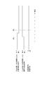
この図3における一旦作動したエンジントルク抑制が解除されてしまう状況を図4のタイミングチャートを参照して説明する。図3の(A)の状態を、図4の(A)時点として示し、図3の(B)の状態を、図4の(B)時点として示し、図3の(C)の状態を、図4の(C)時点として示す。 The situation in which the engine torque suppression once actuated in FIG. 3 is canceled will be described with reference to the timing chart of FIG. The state of (A) of FIG. 3 is shown as (A) time point of FIG. 4, the state of (B) of FIG. 3 is shown as time point (B) of FIG. 4, and the state of (C) of FIG. It shows as time (C) of FIG.
従って、図4の(A)時点においては、第1受発信部11aによって障害物検出有り、第2受発信部11b、11cによって障害物検出無しであり、その結果誤発進抑制制御が作動している。図4の(B)時点においては、第1受発信部11a及び第2受発信部11b、11cによって共に障害物検出無しであり、その結果、誤発進抑制制御の作動が解除されている。図4の(C)時点においては、第1受発信部11aによって障害物検出無し、第2受発信部11b、11cによって障害物検出有りであり、その結果誤発進抑制制御が作動している。
従って、図4の(B)時点では、一旦作動したエンジントルク抑制が解除されてしまい、障害物への衝突の危険性が増大する。
Therefore, at the time of (A) in FIG. 4, there is an obstacle detection by the first transmission /
Therefore, at time (B) in FIG. 4, the engine torque suppression that has been activated once is released, and the risk of collision with an obstacle increases.
本実施形態では、障害物検知部15の有効レンジ制御部19で、左右両側に設置される第2受発信部11b、11cからの赤外線ビームの最大有効レンジ(最大有効距離)を、図2、(B)に示すように、初期値L1から延長値L2に可変制御することで改善している。
In this embodiment, the effective
この改善される状態を、図3、4に対応させて図5、6を参照して説明する。
(1)図5(A)のように、中央の領域α1(図2(A))及び領域β1内において最大有効レンジL3内に障害物5が入ると、まず、障害物5の存在を検知して、後述するエンジントルク抑制制御が開始されて加速、発進が抑制される。この図5(A)は、図3(A)と同様である。
(2)さらに車両1が前進すると、図5(B)のように、第1受発信部11aの上下方向の広がり角度(β1)の下方に潜り込む場合があるが、第1受発信部11aによって障害物5が検出されたとき、その後、第1受発信部11aによって障害物が検出されなくなると予測して、第2受発信部11b、11cからの赤外線ビームの最大有効レンジ(最大有効距離)を延長値L2に延長する。この延長によって障害物5が第2受発信部11b、11cの最大有効レンジ内に入り障害物5が検出されるようになる。
This improved state will be described with reference to FIGS. 5 and 6 in correspondence with FIGS.
(1) As shown in FIG. 5A, when the
(2) When the
この図5における第2受発信部11b、11cによって障害物が検出できるようになる状況を図6のタイミングチャートを参照して説明する。図5の(A)の状態を、図6の(A)時点として示し、図5の(B)の状態を、図6の(B)時点として示す。
A situation where an obstacle can be detected by the second transmission /
従って、図6の(A)時点においては、第1受発信部11aによって障害物検出有り、第2受発信部11b、11cによって障害物検出無しであり、その結果誤発進抑制制御が作動している。図6の(B)時点においては、第1受発信部11aによって障害物検出無し、第2受発信部11b、11cによって障害物検出有りであり、その結果、誤発進抑制制御が作動している。
従って、図6に示すように、エンジントルク抑制が一旦解除されることなく継続されるため、障害物への衝突の危険性が改善される。
Therefore, at the time of (A) in FIG. 6, there is an obstacle detection by the first transmission /
Therefore, as shown in FIG. 6, since the engine torque suppression is continued without being released once, the risk of collision with an obstacle is improved.
最大有効レンジ(最大有効距離)の初期値L1は、図2(A)に示すように、車両1の車体幅Wの延長線と第2受発信部11b、11cの領域α2の左右境界線との交差する位置までの距離としている。
このように、初期値L1は、車体幅Wの延長線と第2受発信部11b、11cからの領域α2の左右境界線との交差する位置までの車両1の前端からの距離であるので、初期値L1の状態においては、車体幅Wより外側の障害物は、検出しないようにして、車両1の前方衝突に影響しない障害物に対する誤判定を低減している。
The initial value L1 of the maximum effective range (maximum effective distance) is, as shown in FIG. 2A, an extension line of the vehicle width W of the
Thus, the initial value L1 is the distance from the front end of the
また、延長値L2は、図2(B)に示すよう車両1の車体幅Wにサイドミラー27の幅Sを加算した幅(W+2S)の延長線と第2受発信部11b、11cからの領域α2の左右境界線との交差する位置までの距離としている。
このように、延長値L2は、車両1の車体幅Wにサイドミラー27の幅Sを加算した幅(W+2S)の延長線と第2受発信部11b、11cからの領域α2の左右境界線との交差する位置までの距離とする。
従って、第2受発信部11b、11cの最大有効レンジを延長しても、それによって正面衝突に影響(関与)しない障害物に対する誤判定を極力低減できる。
なお、サイドミラー27の幅Sだけに限らず、サイドミラー27の幅にさらにプラスアルファ(cm)加算した値として設定してもよく、試験等に基づいて誤判定を生じないレベルとして設定することができる。
Further, as shown in FIG. 2B, the extension value L2 is an extension line of a width (W + 2S) obtained by adding the width S of the
Thus, the extension value L2 is an extension line of a width (W + 2S) obtained by adding the width S of the
Therefore, even if the maximum effective range of the second transmission /
The value may be set as a value obtained by adding plus alpha (cm) to the width of the
次に、誤発進抑制装置7について説明する。この誤発進抑制装置7は、図1に示すように、大きく分けるとECU(電子制御コントロールユニット)からなる制御装置9と、エンジンのトルク抑制制御を実行するエンジン制御部29とを備えて構成されている。
制御装置9には、誤発進抑制部25を備え、該誤発進抑制部25にはさらにトルク抑制制御部31が備えられている。
Next, the erroneous
The control device 9 includes an erroneous
エンジンのトルク抑制制御を実行するエンジン制御部29は、車速センサ21の信号やアクセル開度センサ23の信号に基づいて、燃料噴射量や点火時期等を制御してエンジン出力を制御するものであり、前述した、障害物検知部15からの障害物5の検知結果の信号に基づいて、エンジン出力を抑制するように制御し、アクセルペダルが踏み込まれたときの車両1の加速または発進を抑制する。
The
次に、図7、8のフローチャートを参照して、制御装置9が行う、障害物検知制御及び誤発進抑制制御について説明する。
図7は、障害物検知制御及び誤発進抑制制御の全体の制御フローチャートであり、図8は、有効レンジ延長フラグ設定のサブルーチンのフローチャートである。
Next, obstacle detection control and erroneous start suppression control performed by the control device 9 will be described with reference to the flowcharts of FIGS. 7 and 8.
FIG. 7 is a control flowchart of the entire obstacle detection control and erroneous start suppression control, and FIG. 8 is a flowchart of a subroutine for setting an effective range extension flag.
図7において、ステップS1で、車速センサ21、アクセル開度センサ23等の車両運転状態を表す各種センサ信号を読み取る。ステップS2で、車両1が所定の車速(例えば10km/h)以下で走行中、または停車中であるかが判定される。
次に、ステップS3で、第2受発信部11b、11cによる障害物検出の最大有効レンジを延長する延長フラグを設定する。この延長フラグの設定のサブルーチンについては後述する。
In FIG. 7, in step S1, various sensor signals such as the
Next, in step S3, an extension flag is set to extend the maximum effective range of obstacle detection by the second transmission /
ステップS4では、ステップS3で設定された延長フラグがONかOFFかを判定する。延長フラグがONの場合にはステップS6に進み、第2受発信部11b、11cによる障害物検出の最大有効レンジを初期値L1から延長値L2に延長する。この延長値L2については、既に説明したように、車体幅Wにサイドミラー27の幅Sを加算した幅(W+2S)まで第2受発信部11b、11cからの赤外線ビームが広がる範囲として設定されている。
また、延長フラグがOFFの場合にはステップS5に進み、第2受発信部11b、11cによる障害物検出の最大有効レンジを初期値L1とする。この初期値L1についても既に説明したように、車体幅Wまで第2受発信部11b、11cからの赤外線ビームが広がる範囲として設定されている。
In step S4, it is determined whether the extension flag set in step S3 is ON or OFF. If the extension flag is ON, the process proceeds to step S6, and the maximum effective range of obstacle detection by the second transmission /
If the extension flag is OFF, the process proceeds to step S5, and the maximum effective range for obstacle detection by the second transmission /
ステップS7では、第1受発信部11a、又は第2受発信部11b、11cで障害物5を検出したか否かを判定し、検出した場合には、ステップS8に進んで、エンジントルク抑制制御判断を実行して、車両1の加速または発進を抑制する。また、ステップS7で障害物5を検出しない場合には、ステップS9に進み、エンジントルク抑制制御判断を禁止する。また、ステップS2で車速が所定車速以下でない場合には、第1受発信部11a、及び第2受発信部11b、11cによる障害物5の検出結果に基づくエンジントルク抑制制御判断を禁止する。
In step S7, it is determined whether or not the
次に、図8を参照して、ステップS3の有効レンジ延長フラグ設定のサブルーチンについて説明する。
ステップS11で、第1受発信部11aによって障害物を検出しているかを判定し、検出している場合には、ステップS12に進んで、第2受発信部11b、11cの最大有効レンジを延長可能とする有効レンジ延長フラグをONにし、延長フラグOFF用タイマを0(ゼロ)にセットする。
ステップS11で、第1受発信部11aによって障害物を検出していないと判定した場合には、ステップS13で、第2受発信部11b、11cの左右の少なくとも何れかで障害物5を検出したか否かを判定する。第2受発信部11b、11cの少なくともいずれかで障害物5を検出している場合には、Yesとなり、図7のステップS8に進んで、エンジントルク抑制制御を実行して、車両1の加速または発進を抑制する。
Next, the subroutine for setting the effective range extension flag in step S3 will be described with reference to FIG.
In step S11, it is determined whether or not an obstacle is detected by the first transmission /
If it is determined in step S11 that the first reception /
また、ステップS13で、第2受発信部11b、11cの何れにおいても障害物5を検出していない場合には、Noとなり、ステップS14に進んで、ステップS14では、第2受発信部11b、11cの有効レンジ延長フラグがONであるか否かを判定する。
判定結果が、Yesで有効レンジ延長フラグがONの場合には、ステップS15で、延長フラグOFF用タイマに制御演算の周期を加算する。すなわち、第1受発信部11aにより障害物を検出できなくなってから第2受発信部11b、11cの有効レンジ延長フラグをOFFするまでの時間を算出する。そして、ステップS16で、延長フラグOFF用タイマが所定値を超えたか否かを判定する。この所定値は、例えば、100m秒〜数秒の範囲の値が好ましい。
このように、所定の時間に限って有効レンジを延長することで、左右の第2受発信部11b、11cによる障害物検出の最大有効レンジを延長しても、それによって、路側帯域の歩行者や設置物等の車両の衝突に影響しない物の誤判定を極力低減できる。
If the
If the determination result is Yes and the effective range extension flag is ON, the period of the control calculation is added to the extension flag OFF timer in step S15. That is, the time until the effective range extension flag of the second transmission /
Thus, even if the maximum effective range of obstacle detection by the second transmission /
ステップS16で、延長フラグOFF用タイマが所定値を超えた場合には、ステップS17で、第2受発信部11b、11cの有効レンジ延長フラグをOFFにし、さらに延長フラグOFF用タイマも0(ゼロ)にリセットする。
If the extension flag OFF timer exceeds the predetermined value in step S16, the effective range extension flags of the second transmission /
以上説明した実施形態によれば、有効レンジ制御部19によって、第1受発信部11aによって障害物5を検出したとき、第2受発信部11b、11による障害物検出の最大有効レンジを初期値L1から延長値L2へ延長することで、中央の赤外線ビームのビーム広がり範囲の外に外れて検知できなくなる範囲を、第2受発信部11b、11cの最大有効レンジを増大させて、第2受発信部11b、11cからの赤外線ビームによって検出可能とすることで、障害物5の検出精度の低下を防止できる。その結果、車両1の誤発進抑制制御の確実性を高めることができる。
According to the embodiment described above, when the
本発明の一実施形態によれば、自車前方に対して中央、及び少なくとも左右方向の一方に赤外線ビームを照射して、前方の障害物を検出する車両の障害物検知装置において、中央の赤外線ビームの最大障害物検出距離を左右いずれか一方の赤外線ビームより長く設定する場合に生じるおそれがある障害物の検出精度の低下を防止して、障害物の検出精度を向上し、さらに車両の誤発進抑制制御の確実性を高めることができるので、車両の障害物検知装置及び誤発進抑制装置への適用に有効である。 According to one embodiment of the present invention, a vehicle infrared ray detecting device for detecting an obstacle ahead by irradiating an infrared beam in the center and at least one of the left and right directions with respect to the front of the vehicle. The detection accuracy of the obstacle that may occur when the maximum obstacle detection distance of the beam is set longer than either of the left and right infrared beams is prevented from being lowered, the detection accuracy of the obstacle is improved, and the vehicle is erroneously Since the certainty of the start suppression control can be enhanced, it is effective for application to an obstacle detection device and a false start suppression device of a vehicle.
1 車両
3 障害物検知装置
5 障害物
7 誤発進抑制装置
9 制御装置
11 障害物センサ部
11a 第1受発信部
11b、11c 第2受発信部
13 走行状態判定部
15 障害物検知部
17 演算部
19 有効レンジ制御部
21 車速センサ
23 アクセル開度センサ
25 誤発進抑制部
27 サイドミラー
31 トルク抑制制御部
L1 第2受発信部による障害物検出の最大有効レンジ(最大有効距離)の初期値
L2 第2受発信部による障害物検出の最大有効レンジ(最大有効距離)の延長値
L3 第1受発信部による障害物検出の最大有効レンジ(最大有効距離)の設定値
W 車体幅
S サイドミラー幅
α1 第1受発信部からの赤外線ビームの水平方向の広がり角度
α2 第2受発信部からの赤外線ビームの水平方向の広がり角度
β1 第1受発信部からの赤外線ビームの上下方向の広がり角度
β2 第2受発信部からの赤外線ビームの上下方向の広がり角度
Claims (5)
車両の幅方向の中央部に設けられ自車前方の中央域に赤外線ビームを発信及び障害物からの反射信号を受信する第1受発信部と、
該第1受発信部の左右両側の少なくとも一方に設けられ前記第1受発信部からの赤外線ビームの検知領域に隣接して左右両側の少なくとも一方に広がるように発信及び障害物からの反射信号を受信する第2受発信部と、
前記第1受発信部による障害物検出の最大有効距離と前記第2受発信部による障害物検出の最大有効距離とを制御する有効レンジ制御部と、を備え、
前記有効レンジ制御部は、前記第1受発信部による最大有効距離を前記第2受発信部による最大有効距離より長く設定すると共に、前記第1受発信部によって障害物を検出したとき、前記第2受発信部の前記最大有効距離のみを初期値より延長することを特徴とする車両の障害物検知装置。 In an obstacle detection device of a vehicle that irradiates an infrared beam ahead of the vehicle and detects an obstacle in front of the vehicle,
A first transmission / reception unit provided at a central portion in the width direction of the vehicle for transmitting an infrared beam to a central region in front of the vehicle and receiving a reflected signal from an obstacle;
A transmission signal and a reflection signal from an obstacle are provided on at least one of the left and right sides of the first transmission and reception unit and spread on at least one of the left and right sides adjacent to the detection region of the infrared beam from the first transmission and reception unit. A second receiving / transmitting unit to receive;
An effective range control unit configured to control a maximum effective distance of obstacle detection by the first transmission / reception unit and a maximum effective distance of obstacle detection by the second transmission / reception unit;
When the effective range control unit sets the maximum effective distance by the first transmission / reception unit to be longer than the maximum effective distance by the second transmission / reception unit, and the obstacle is detected by the first transmission / reception unit, (2) An obstacle detection device for a vehicle, wherein only the maximum effective distance of the reception / transmission unit is extended from an initial value.
Priority Applications (3)
| Application Number | Priority Date | Filing Date | Title |
|---|---|---|---|
| JP2014241418A JP6500403B2 (en) | 2014-11-28 | 2014-11-28 | Vehicle obstacle detection device and false start suppression device using the same |
| EP15196662.9A EP3026656B1 (en) | 2014-11-28 | 2015-11-27 | Obstacle detection device for vehicle and misacceleration mitigation device using the same |
| US14/953,097 US9528461B2 (en) | 2014-11-28 | 2015-11-27 | Obstacle detection device for vehicle and misacceleration mitigation device using the same |
Applications Claiming Priority (1)
| Application Number | Priority Date | Filing Date | Title |
|---|---|---|---|
| JP2014241418A JP6500403B2 (en) | 2014-11-28 | 2014-11-28 | Vehicle obstacle detection device and false start suppression device using the same |
Related Child Applications (2)
| Application Number | Title | Priority Date | Filing Date |
|---|---|---|---|
| JP2018172634A Division JP6597860B2 (en) | 2018-09-14 | 2018-09-14 | Vehicle obstacle detection device and erroneous start suppression device using the same |
| JP2018172635A Division JP6597861B2 (en) | 2018-09-14 | 2018-09-14 | Vehicle obstacle detection device and erroneous start suppression device using the same |
Publications (2)
| Publication Number | Publication Date |
|---|---|
| JP2016103176A JP2016103176A (en) | 2016-06-02 |
| JP6500403B2 true JP6500403B2 (en) | 2019-04-17 |
Family
ID=54707633
Family Applications (1)
| Application Number | Title | Priority Date | Filing Date |
|---|---|---|---|
| JP2014241418A Active JP6500403B2 (en) | 2014-11-28 | 2014-11-28 | Vehicle obstacle detection device and false start suppression device using the same |
Country Status (3)
| Country | Link |
|---|---|
| US (1) | US9528461B2 (en) |
| EP (1) | EP3026656B1 (en) |
| JP (1) | JP6500403B2 (en) |
Cited By (1)
| Publication number | Priority date | Publication date | Assignee | Title |
|---|---|---|---|---|
| US11175279B2 (en) | 2010-05-03 | 2021-11-16 | Creatv Microtech, Inc. | Polymer microfilters, devices comprising the same, methods of manufacturing the same, and uses thereof |
Families Citing this family (5)
| Publication number | Priority date | Publication date | Assignee | Title |
|---|---|---|---|---|
| JPWO2018043540A1 (en) * | 2016-08-31 | 2019-06-24 | パイオニア株式会社 | Control device, control method, and program |
| JP6443418B2 (en) * | 2016-10-03 | 2018-12-26 | トヨタ自動車株式会社 | Vehicle driving support device |
| CN107561546B (en) * | 2017-08-22 | 2021-05-28 | 广东美的制冷设备有限公司 | Infrared detection method, infrared detection device and air conditioner |
| GB2570910A (en) * | 2018-02-09 | 2019-08-14 | Hi Tec Security Systems Ltd | Method and system for targeting and tracking an intruder using a laser detection and ranging device |
| WO2020219694A1 (en) * | 2019-04-23 | 2020-10-29 | Apple Inc. | Systems and methods for resolving hidden features in a field of view |
Family Cites Families (20)
| Publication number | Priority date | Publication date | Assignee | Title |
|---|---|---|---|---|
| JP2910377B2 (en) * | 1992-01-20 | 1999-06-23 | 日産自動車株式会社 | Radar equipment for vehicles |
| JPH06147887A (en) * | 1992-10-30 | 1994-05-27 | Nippon Seiki Co Ltd | Distance detector for vehicle |
| JP3128176B2 (en) * | 1993-05-24 | 2001-01-29 | マツダ株式会社 | Vehicle obstacle detection device |
| US7663333B2 (en) * | 2001-06-12 | 2010-02-16 | Irobot Corporation | Method and system for multi-mode coverage for an autonomous robot |
| JP4003586B2 (en) * | 2002-08-28 | 2007-11-07 | 日産自動車株式会社 | Inter-vehicle distance measuring device |
| JP4006319B2 (en) * | 2002-11-08 | 2007-11-14 | 株式会社小松製作所 | Vehicle travel control device |
| DE10351915A1 (en) * | 2003-11-07 | 2005-06-09 | Volkswagen Ag | Monitoring device for a vehicle for detecting obstacles in front or behind it has a sensor device for which a monitoring surface of variable area can be defined dependent on the vehicle configuration |
| JP5287007B2 (en) * | 2008-07-28 | 2013-09-11 | 日産自動車株式会社 | Lane departure prevention apparatus and method |
| JP5644477B2 (en) * | 2010-12-22 | 2014-12-24 | 日産自動車株式会社 | Driving support display device |
| JP5983156B2 (en) * | 2012-07-31 | 2016-08-31 | マツダ株式会社 | Vehicle erroneous start suppressing device |
| US20150254861A1 (en) * | 2012-10-18 | 2015-09-10 | T. Eric Chornenky | Apparatus and method for determining spatial information about environment |
| US9069080B2 (en) * | 2013-05-24 | 2015-06-30 | Advanced Scientific Concepts, Inc. | Automotive auxiliary ladar sensor |
| US20160192876A1 (en) * | 2015-01-02 | 2016-07-07 | Hello Inc. | Room monitoring device and sleep analysis |
| US9610030B2 (en) * | 2015-01-23 | 2017-04-04 | Hello Inc. | Room monitoring device and sleep analysis methods |
| WO2015006917A1 (en) * | 2013-07-16 | 2015-01-22 | 北京机械设备研究所 | Control system of a fire truck for high-rise and super high-rise building firefighting |
| WO2015006916A1 (en) * | 2013-07-16 | 2015-01-22 | 北京机械设备研究所 | Control method of a fire truck for high-rise and super high-rise building firefighting |
| CN103958004B (en) * | 2013-07-16 | 2016-01-13 | 北京机械设备研究所 | Be applicable to fire fighting truck that is high-rise and high-rise building fire attack |
| EP3152010A4 (en) * | 2014-06-04 | 2018-01-24 | Intelligrated Headquarters LLC | Truck unloader visualization |
| US9575184B2 (en) * | 2014-07-03 | 2017-02-21 | Continental Advanced Lidar Solutions Us, Inc. | LADAR sensor for a dense environment |
| US9776511B2 (en) * | 2014-07-08 | 2017-10-03 | Rite-Hite Holding Corporation | Vehicle alignment systems for loading docks |
-
2014
- 2014-11-28 JP JP2014241418A patent/JP6500403B2/en active Active
-
2015
- 2015-11-27 US US14/953,097 patent/US9528461B2/en active Active
- 2015-11-27 EP EP15196662.9A patent/EP3026656B1/en active Active
Cited By (2)
| Publication number | Priority date | Publication date | Assignee | Title |
|---|---|---|---|---|
| US11175279B2 (en) | 2010-05-03 | 2021-11-16 | Creatv Microtech, Inc. | Polymer microfilters, devices comprising the same, methods of manufacturing the same, and uses thereof |
| US11860157B2 (en) | 2010-05-03 | 2024-01-02 | Creatv Microtech, Inc. | Polymer microfilters, devices comprising the same, methods of manufacturing the same, and uses thereof |
Also Published As
| Publication number | Publication date |
|---|---|
| EP3026656A1 (en) | 2016-06-01 |
| EP3026656B1 (en) | 2017-02-08 |
| US9528461B2 (en) | 2016-12-27 |
| US20160153380A1 (en) | 2016-06-02 |
| JP2016103176A (en) | 2016-06-02 |
Similar Documents
| Publication | Publication Date | Title |
|---|---|---|
| JP6500403B2 (en) | Vehicle obstacle detection device and false start suppression device using the same | |
| US10220842B2 (en) | Vehicle control device | |
| US10780884B2 (en) | Vehicle cruise control apparatus and vehicle cruise control method | |
| US10486698B2 (en) | Vehicle cruise control device and cruise control method | |
| WO2016038773A1 (en) | Collision prevention device | |
| JP6729282B2 (en) | Vehicle control device | |
| JP6155963B2 (en) | Collision mitigation device | |
| US20190344784A1 (en) | Vehicle collision mitigation apparatus and method | |
| JP7176415B2 (en) | Pre-collision control device | |
| KR102106345B1 (en) | Rear-side alert system and controlling method thereof | |
| JP2017538183A (en) | Lane change detection | |
| JP6613223B2 (en) | Travel control device | |
| JP5983156B2 (en) | Vehicle erroneous start suppressing device | |
| JP5075656B2 (en) | Object detection device | |
| JP2010091317A (en) | Radar system | |
| JP5396142B2 (en) | Vehicle travel safety device | |
| JP6187769B2 (en) | Follow-up control device | |
| JP6597860B2 (en) | Vehicle obstacle detection device and erroneous start suppression device using the same | |
| JP6597861B2 (en) | Vehicle obstacle detection device and erroneous start suppression device using the same | |
| KR102413579B1 (en) | Apparatus for making a driver operate a car easily and target estimation method thereof | |
| JP2008143429A (en) | Collision predicting device | |
| JP2014119285A (en) | Object detection apparatus | |
| JP5754420B2 (en) | Vehicle alarm device | |
| JP6477377B2 (en) | Vehicle control apparatus and vehicle control method | |
| KR102261540B1 (en) | Method for controlling vehicle speed in the smart cruise control system |
Legal Events
| Date | Code | Title | Description |
|---|---|---|---|
| A621 | Written request for application examination |
Free format text: JAPANESE INTERMEDIATE CODE: A621 Effective date: 20171027 |
|
| A131 | Notification of reasons for refusal |
Free format text: JAPANESE INTERMEDIATE CODE: A131 Effective date: 20180720 |
|
| A977 | Report on retrieval |
Free format text: JAPANESE INTERMEDIATE CODE: A971007 Effective date: 20180718 |
|
| A521 | Request for written amendment filed |
Free format text: JAPANESE INTERMEDIATE CODE: A523 Effective date: 20180914 |
|
| TRDD | Decision of grant or rejection written | ||
| A01 | Written decision to grant a patent or to grant a registration (utility model) |
Free format text: JAPANESE INTERMEDIATE CODE: A01 Effective date: 20190219 |
|
| A61 | First payment of annual fees (during grant procedure) |
Free format text: JAPANESE INTERMEDIATE CODE: A61 Effective date: 20190304 |
|
| R151 | Written notification of patent or utility model registration |
Ref document number: 6500403 Country of ref document: JP Free format text: JAPANESE INTERMEDIATE CODE: R151 |