JP6287360B2 - Inspection device - Google Patents
Inspection device Download PDFInfo
- Publication number
- JP6287360B2 JP6287360B2 JP2014043754A JP2014043754A JP6287360B2 JP 6287360 B2 JP6287360 B2 JP 6287360B2 JP 2014043754 A JP2014043754 A JP 2014043754A JP 2014043754 A JP2014043754 A JP 2014043754A JP 6287360 B2 JP6287360 B2 JP 6287360B2
- Authority
- JP
- Japan
- Prior art keywords
- axis
- substrate
- opening
- illumination
- light
- Prior art date
- Legal status (The legal status is an assumption and is not a legal conclusion. Google has not performed a legal analysis and makes no representation as to the accuracy of the status listed.)
- Active
Links
Images


Classifications
-
- G—PHYSICS
- G01—MEASURING; TESTING
- G01B—MEASURING LENGTH, THICKNESS OR SIMILAR LINEAR DIMENSIONS; MEASURING ANGLES; MEASURING AREAS; MEASURING IRREGULARITIES OF SURFACES OR CONTOURS
- G01B11/00—Measuring arrangements characterised by the use of optical techniques
- G01B11/24—Measuring arrangements characterised by the use of optical techniques for measuring contours or curvatures
- G01B11/25—Measuring arrangements characterised by the use of optical techniques for measuring contours or curvatures by projecting a pattern, e.g. one or more lines, moiré fringes on the object
- G01B11/254—Projection of a pattern, viewing through a pattern, e.g. moiré
-
- G—PHYSICS
- G01—MEASURING; TESTING
- G01B—MEASURING LENGTH, THICKNESS OR SIMILAR LINEAR DIMENSIONS; MEASURING ANGLES; MEASURING AREAS; MEASURING IRREGULARITIES OF SURFACES OR CONTOURS
- G01B11/00—Measuring arrangements characterised by the use of optical techniques
- G01B11/24—Measuring arrangements characterised by the use of optical techniques for measuring contours or curvatures
- G01B11/25—Measuring arrangements characterised by the use of optical techniques for measuring contours or curvatures by projecting a pattern, e.g. one or more lines, moiré fringes on the object
- G01B11/2531—Measuring arrangements characterised by the use of optical techniques for measuring contours or curvatures by projecting a pattern, e.g. one or more lines, moiré fringes on the object using several gratings, projected with variable angle of incidence on the object, and one detection device
-
- G—PHYSICS
- G01—MEASURING; TESTING
- G01N—INVESTIGATING OR ANALYSING MATERIALS BY DETERMINING THEIR CHEMICAL OR PHYSICAL PROPERTIES
- G01N21/00—Investigating or analysing materials by the use of optical means, i.e. using sub-millimetre waves, infrared, visible or ultraviolet light
- G01N21/84—Systems specially adapted for particular applications
- G01N21/88—Investigating the presence of flaws or contamination
- G01N21/8806—Specially adapted optical and illumination features
- G01N2021/8812—Diffuse illumination, e.g. "sky"
- G01N2021/8816—Diffuse illumination, e.g. "sky" by using multiple sources, e.g. LEDs
-
- G—PHYSICS
- G01—MEASURING; TESTING
- G01N—INVESTIGATING OR ANALYSING MATERIALS BY DETERMINING THEIR CHEMICAL OR PHYSICAL PROPERTIES
- G01N21/00—Investigating or analysing materials by the use of optical means, i.e. using sub-millimetre waves, infrared, visible or ultraviolet light
- G01N21/84—Systems specially adapted for particular applications
- G01N21/88—Investigating the presence of flaws or contamination
- G01N21/8806—Specially adapted optical and illumination features
- G01N2021/8845—Multiple wavelengths of illumination or detection
-
- G—PHYSICS
- G01—MEASURING; TESTING
- G01N—INVESTIGATING OR ANALYSING MATERIALS BY DETERMINING THEIR CHEMICAL OR PHYSICAL PROPERTIES
- G01N21/00—Investigating or analysing materials by the use of optical means, i.e. using sub-millimetre waves, infrared, visible or ultraviolet light
- G01N21/84—Systems specially adapted for particular applications
- G01N21/88—Investigating the presence of flaws or contamination
- G01N21/95—Investigating the presence of flaws or contamination characterised by the material or shape of the object to be examined
- G01N21/956—Inspecting patterns on the surface of objects
- G01N2021/95638—Inspecting patterns on the surface of objects for PCB's
- G01N2021/95646—Soldering
-
- G—PHYSICS
- G01—MEASURING; TESTING
- G01N—INVESTIGATING OR ANALYSING MATERIALS BY DETERMINING THEIR CHEMICAL OR PHYSICAL PROPERTIES
- G01N2201/00—Features of devices classified in G01N21/00
- G01N2201/06—Illumination; Optics
- G01N2201/062—LED's
- G01N2201/0627—Use of several LED's for spectral resolution
-
- G—PHYSICS
- G01—MEASURING; TESTING
- G01N—INVESTIGATING OR ANALYSING MATERIALS BY DETERMINING THEIR CHEMICAL OR PHYSICAL PROPERTIES
- G01N2201/00—Features of devices classified in G01N21/00
- G01N2201/06—Illumination; Optics
- G01N2201/063—Illuminating optical parts
- G01N2201/0634—Diffuse illumination
Description
本発明は、部品がはんだ付けされた基板の検査装置に関する。 The present invention relates to an inspection apparatus for a board on which components are soldered.
リフロー後の基板をカメラで撮影し、得られた画像を解析することで部品のはんだ接合の良否を検査する検査装置が知られている。この種の検査装置では、R,G,Bの照明を異なる入射角ではんだ面に当て、各色の反射光をカメラで撮影することで、はんだフィレットの3次元形状を2次元の色相情報として画像化する方法(いわゆるカラーハイライト方式)が用いられることが多い。また最近では、はんだ形状計測用の照明に加え、拡散物体の3次元形状(部品本体の高さなど)を計測するためのパタン光を投射する投影装置を搭載した検査装置もある(特許文献1、2参照)。 2. Description of the Related Art An inspection apparatus that inspects the quality of solder bonding of components by photographing a substrate after reflow with a camera and analyzing the obtained image is known. In this type of inspection apparatus, R, G, and B illuminations are applied to the solder surface at different incident angles, and the reflected light of each color is photographed with a camera, so that the three-dimensional shape of the solder fillet is imaged as two-dimensional hue information. In many cases (so-called color highlighting) is used. Recently, in addition to illumination for solder shape measurement, there is also an inspection device equipped with a projection device that projects pattern light for measuring the three-dimensional shape of a diffused object (such as the height of a component body) (Patent Document 1). 2).
図12に、特許文献1の検査装置の構成を模式的に示す。この検査装置では、青色照明101B、緑色照明101G、赤色照明101Rの3つのリング状照明ではんだ形状計測用の照明装置が構成されており、X軸方向左右に2台の投影装置103が設置されている。はんだ形状を計測する際には、照明101B,101G,101Rを用いて基板104に青色光B、緑色光G、赤色光Rを照射し、その反射光をZ軸上に配置されたカメラ102で撮影する。また、部品高さを計測する際には、左右の投影装置103から縞状のパタン光Lを投射し、カメラ102で撮影を行う。
FIG. 12 schematically shows the configuration of the inspection apparatus disclosed in
パタン光Lは基板104に対し斜めの方向から投射しなければならない。そのため、従来装置では、図12に示すようにリング状照明101Bと101Gの間隔を大きくとり、そのあいだに投影装置103を配置するか、特許文献2のように照明装置の中腹にパタン光投影用の開口を形成することで、照明装置と投影装置の物理的干渉を回避している。
The pattern light L must be projected on the
しかしながら、照明装置に隙間や開口を設けると、図12に示すように照明光に抜けが生じ、はんだ形状の計測性能を低下させてしまうという問題が発生する。言い換えると、はんだフィレット表面の傾斜を精度よく計測するには、照明装置の照明光が入射角方向(天頂角方向)に広く連続した角度レンジを有することが望ましいところ、従来装置では、パタン光投影のために照明光の角度レンジの一部を犠牲にしていたのである。 However, if a gap or an opening is provided in the lighting device, there is a problem that the illumination light is lost as shown in FIG. 12 and the measurement performance of the solder shape is deteriorated. In other words, in order to accurately measure the inclination of the solder fillet surface, it is desirable that the illumination light of the illumination device has a wide and continuous angle range in the incident angle direction (zenith angle direction). Because of this, part of the angular range of the illumination light was sacrificed.
本発明は上記実情に鑑みなされたものであり、その目的とするところは、パタン光を投影する投影装置を有する検査装置において、はんだ形状の良好な計測性能を実現するための技術を提供することにある。 The present invention has been made in view of the above circumstances, and an object of the present invention is to provide a technique for realizing good measurement performance of a solder shape in an inspection apparatus having a projection device that projects pattern light. It is in.
本発明の第一態様は、部品がはんだ付けされた基板を垂直方向から撮影するカメラを有する検査装置であって、検査装置内に搬送された基板と前記カメラの光軸との交点を原点とし、基板表面に平行で且つ基板の搬送方向に平行にX軸、基板表面に平行で且つ基板の搬送方向に垂直にY軸、基板表面に垂直にZ軸をとり、Z軸となす角を天頂角、原点から
見たXY面内における方向を方位という場合に、天頂角に応じて色又は輝度が段階的若しくは連続的に変化する照明光を全方位から基板に対し照射可能に構成された照明装置と、Z軸に対し斜めの方向から、パタン光を基板に対し投影可能に構成された一つ又は複数の投影装置と、前記照明装置を点灯した状態、又は、前記投影装置から前記パタン光を投影した状態で前記カメラにより撮影された基板の画像を用いて検査を行う処理装置と、を有し、前記投影装置は、前記照明装置に設けられた開口を通して、パタン光を基板に対し投影するものであり、前記開口は、原点から見て、X軸方向とY軸方向のいずれとも異なる方位に設けられていることを特徴とする検査装置である。
A first aspect of the present invention is an inspection apparatus having a camera for photographing a substrate on which a component is soldered from a vertical direction, and an origin is an intersection of the substrate conveyed into the inspection apparatus and the optical axis of the camera. The X axis is parallel to the substrate surface and parallel to the substrate transport direction, the Y axis is parallel to the substrate surface and perpendicular to the substrate transport direction, and the Z axis is perpendicular to the substrate surface. When the direction in the XY plane viewed from the angle and the origin is called the azimuth, the illumination is configured so that the illumination light whose color or luminance changes stepwise or continuously according to the zenith angle can be irradiated to the substrate from all directions The apparatus, one or a plurality of projection devices configured to project pattern light onto the substrate from a direction oblique to the Z axis, and the illumination device being turned on, or the pattern light from the projection device Taken with the camera A processing apparatus that performs an inspection using an image of the substrate that has been formed, and the projection device projects pattern light onto the substrate through an opening provided in the illumination device, The inspection apparatus is provided in different orientations in both the X-axis direction and the Y-axis direction when viewed from the origin.
本発明の第二態様は、部品がはんだ付けされた基板を垂直方向から撮影するカメラを有する検査装置であって、検査装置内に搬送された基板と前記カメラの光軸との交点を原点とし、基板表面に平行で且つ基板の搬送方向に平行にX軸、基板表面に平行で且つ基板の搬送方向に垂直にY軸、基板表面に垂直にZ軸をとり、Z軸となす角を天頂角、原点から見たXY面内における方向を方位という場合に、天頂角に応じて色又は輝度が段階的若しくは連続的に変化する照明光を全方位から基板に対し照射可能に構成された照明装置と、前記照明装置に設けられた開口を通して、Z軸に対し斜めの方向から、パタン光を基板に対し投影可能に構成された一つ又は複数の投影装置と、前記照明装置に設けられた開口による照明光の欠損を補う補完光を、基板に対し照射する補完照明装置と、前記照明装置及び前記補完照明装置を点灯させた状態、又は、前記投影装置から前記パタン光を投影した状態で前記カメラにより撮影された基板の画像を用いて検査を行う処理装置と、を有することを特徴とする検査装置である。 According to a second aspect of the present invention, there is provided an inspection apparatus having a camera for photographing a substrate on which a component is soldered from a vertical direction, and an origin is an intersection of the substrate conveyed into the inspection apparatus and the optical axis of the camera. The X axis is parallel to the substrate surface and parallel to the substrate transport direction, the Y axis is parallel to the substrate surface and perpendicular to the substrate transport direction, and the Z axis is perpendicular to the substrate surface. When the direction in the XY plane viewed from the angle and the origin is called the azimuth, the illumination is configured so that the illumination light whose color or luminance changes stepwise or continuously according to the zenith angle can be irradiated to the substrate from all directions An apparatus, one or a plurality of projection apparatuses configured to project pattern light onto a substrate from a direction oblique to the Z axis through an opening provided in the illumination apparatus, and the illumination apparatus. Complementary light to compensate for the loss of illumination light due to the aperture A complementary illumination device for irradiating the substrate, and an image of the substrate photographed by the camera in a state where the illumination device and the complementary illumination device are turned on or in a state where the pattern light is projected from the projection device And a processing device for performing inspection.
本発明の第三態様は、部品がはんだ付けされた基板を垂直方向から撮影するカメラを有する検査装置であって、検査装置内に搬送された基板と前記カメラの光軸との交点を原点とし、基板表面に平行で且つ基板の搬送方向に平行にX軸、基板表面に平行で且つ基板の搬送方向に垂直にY軸、基板表面に垂直にZ軸をとり、Z軸となす角を天頂角、原点から見たXY面内における方向を方位という場合に、天頂角に応じて色又は輝度が段階的若しくは連続的に変化する照明光を全方位から基板に対し照射可能に構成された照明装置と、前記照明装置に設けられた開口を通して、Z軸に対し斜めの方向から、パタン光を基板に対し投影可能に構成された一つ又は複数の投影装置と、前記照明装置に設けられた開口を通して、Z軸に対して斜めの方向から、基板を撮影する一つ又は複数の斜視カメラと、前記照明装置を点灯した状態もしくは前記投影装置から前記パタン光を投影した状態で前記カメラにより撮影された基板の画像、又は、前記照明装置を点灯した状態で前記斜視カメラにより撮影された基板の画像を用いて検査を行う処理装置と、を有し、前記投影装置用の開口と前記斜視カメラ用の開口とが、原点から見て、異なる方位に設けられていることを特徴とする検査装置である。 According to a third aspect of the present invention, there is provided an inspection apparatus having a camera for photographing a substrate on which a component is soldered from a vertical direction, and an origin is an intersection of the substrate conveyed into the inspection apparatus and the optical axis of the camera. The X axis is parallel to the substrate surface and parallel to the substrate transport direction, the Y axis is parallel to the substrate surface and perpendicular to the substrate transport direction, and the Z axis is perpendicular to the substrate surface. When the direction in the XY plane viewed from the angle and the origin is called the azimuth, the illumination is configured so that the illumination light whose color or luminance changes stepwise or continuously according to the zenith angle can be irradiated to the substrate from all directions An apparatus, one or a plurality of projection apparatuses configured to project pattern light onto a substrate from a direction oblique to the Z axis through an opening provided in the illumination apparatus, and the illumination apparatus. Through the opening, diagonal to the Z axis From one or a plurality of perspective cameras for photographing a substrate and an image of the substrate photographed by the camera in a state where the illumination device is turned on or in a state where the pattern light is projected from the projection device, or the illumination device A processing device that performs inspection using an image of the substrate photographed by the perspective camera in a lit state, and the opening for the projection device and the opening for the perspective camera are viewed from the origin, The inspection apparatus is provided in different directions.
本発明の第四態様は、部品がはんだ付けされた基板を垂直方向から撮影するカメラを有する検査装置であって、検査装置内に搬送された基板と前記カメラの光軸との交点を原点とし、基板表面に平行で且つ基板の搬送方向に平行にX軸、基板表面に平行で且つ基板の搬送方向に垂直にY軸、基板表面に垂直にZ軸をとり、Z軸となす角を天頂角、原点から見たXY面内における方向を方位という場合に、天頂角に応じて色又は輝度が段階的若しくは連続的に変化する照明光を全方位から基板に対し照射可能に構成された照明装置と、前記照明装置に設けられた開口を通して、Z軸に対し斜めの方向から、パタン光を基板に対し投影可能に構成された一つ又は複数の投影装置と、前記照明装置に設けられた開口を通して、Z軸に対して斜めの方向から、基板を撮影する一つ又は複数の斜視カメラと、前記照明装置を点灯した状態もしくは前記投影装置から前記パタン光を投影した状態で前記カメラにより撮影された基板の画像、又は、前記照明装置を点灯した状態で前記斜視カメラにより撮影された基板の画像を用いて検査を行う処理装置と、前記投影装置の光軸と前記斜視カメラの光軸を一致させる光学部材と、を有し、前記投影装置用の開口が前記斜視
カメラ用の開口を兼ねていることを特徴とする検査装置である。
According to a fourth aspect of the present invention, there is provided an inspection apparatus having a camera for photographing a substrate to which a component is soldered from a vertical direction, and an origin is an intersection of the substrate conveyed into the inspection apparatus and the optical axis of the camera. The X axis is parallel to the substrate surface and parallel to the substrate transport direction, the Y axis is parallel to the substrate surface and perpendicular to the substrate transport direction, and the Z axis is perpendicular to the substrate surface. When the direction in the XY plane viewed from the angle and the origin is called the azimuth, the illumination is configured so that the illumination light whose color or luminance changes stepwise or continuously according to the zenith angle can be irradiated to the substrate from all directions An apparatus, one or a plurality of projection apparatuses configured to project pattern light onto a substrate from a direction oblique to the Z axis through an opening provided in the illumination apparatus, and the illumination apparatus. Through the opening, diagonal to the Z axis From one or a plurality of perspective cameras for photographing a substrate and an image of the substrate photographed by the camera in a state where the illumination device is turned on or in a state where the pattern light is projected from the projection device, or the illumination device A processing device that performs inspection using an image of a substrate photographed by the perspective camera in a state where the light is turned on, and an optical member that matches the optical axis of the projection device and the optical axis of the perspective camera, and An inspection apparatus characterized in that an opening for a projection device also serves as an opening for the perspective camera.
以上述べた各態様の検査装置によれば、投影装置用の開口や斜視カメラ用の開口による照明光の抜けがはんだ形状の計測に与え得る影響を従来よりも小さくでき、安定した形状計測を実現することができる。 According to the inspection apparatus of each aspect described above, the influence that omission of illumination light by the opening for the projection device and the opening for the perspective camera can have on the measurement of the solder shape can be made smaller than before, and stable shape measurement is realized. can do.
第一態様ないし第四態様の検査装置において、前記照明装置は、ドーム状の発光領域を有する照明装置であり、少なくともX軸正方向、X軸負方向、Y軸正方向、Y軸負方向の四つの方位では、最小の天頂角から最大の天頂角まで前記発光領域が連続しているとよい。あるいは、前記照明装置は、色又は輝度が異なる複数の発光体を天頂角を変えて配置した照明装置であり、少なくともX軸正方向、X軸負方向、Y軸正方向、Y軸負方向の四つの方位では、前記複数の発光体が略隙間なく並べられているとよい。かかる構成の照明装置を用いることで、X軸正方向、X軸負方向、Y軸正方向、Y軸負方向に向いたはんだフィレットの傾斜面の形状を精度よく計測することが可能となる。 In the inspection apparatus according to the first aspect to the fourth aspect, the illuminating apparatus is an illuminating apparatus having a dome-shaped light emitting region, and is at least in the X-axis positive direction, the X-axis negative direction, the Y-axis positive direction, and the Y-axis negative direction. In the four directions, the light emitting region may be continuous from the minimum zenith angle to the maximum zenith angle. Or the said illuminating device is an illuminating device which has arrange | positioned the several light-emitting body from which a color or brightness | luminance changes, changing a zenith angle, At least X-axis positive direction, X-axis negative direction, Y-axis positive direction, Y-axis negative direction In the four directions, the plurality of light emitters may be arranged substantially without gaps. By using the illuminating device having such a configuration, it is possible to accurately measure the shape of the inclined surface of the solder fillet oriented in the X-axis positive direction, the X-axis negative direction, the Y-axis positive direction, and the Y-axis negative direction.
第一態様ないし第四態様の検査装置において、X軸正方向の方位角を0度とした場合に、前記開口は、原点から見て、約45度、約135度、約225度、約315度のうちのいずれかの方位に設けられているとよい。X軸方向とY軸方向のいずれからも最も遠い方位に配置することで、開口による影響を最小限にできるからである。 In the inspection apparatus according to the first aspect to the fourth aspect, when the azimuth angle in the positive direction of the X axis is 0 degree, the opening is about 45 degrees, about 135 degrees, about 225 degrees, about 315 when viewed from the origin. It is good to be provided in any orientation of degrees. This is because the influence of the opening can be minimized by disposing in the direction farthest from both the X-axis direction and the Y-axis direction.
第一態様ないし第四態様の検査装置において、二つの投影装置を有しており、一方の投影装置用の開口と他方の投影装置用の開口とが、原点から見て、180度異なる方位に設けられているとよい。これにより、二つの投影装置だけで、基板上の計測対象の略全体をカバーすることができる。 The inspection apparatus according to the first aspect to the fourth aspect includes two projection apparatuses, and the opening for one projection apparatus and the opening for the other projection apparatus are in directions different from each other by 180 degrees when viewed from the origin. It should be provided. Thereby, it is possible to cover substantially the entire measurement target on the substrate with only two projection apparatuses.
第一態様又は第二態様の検査装置において、前記照明装置に設けられた開口を通して、Z軸に対して斜めの方向から、基板を撮影する一つ又は複数の斜視カメラをさらに有することも好ましい。 In the inspection apparatus according to the first aspect or the second aspect, it is preferable that the inspection apparatus further includes one or a plurality of perspective cameras that photograph the substrate from a direction oblique to the Z axis through an opening provided in the illumination device.
上記構成および処理の各々は技術的な矛盾が生じない限り互いに組み合わせて本発明を構成することができる。 Each of the above configurations and processes can be combined with each other as long as no technical contradiction occurs.
本発明によれば、パタン光を投影する投影装置を有する検査装置において、はんだ形状の良好な計測性能を実現することができる。 ADVANTAGE OF THE INVENTION According to this invention, in the inspection apparatus which has a projection apparatus which projects pattern light, the favorable measurement performance of a solder shape is realizable.
本発明は、部品がはんだ付けされた基板(リフロー後基板)のはんだ接合の良否を検査するための基板外観検査装置(以下、単に「検査装置」と呼ぶ)に関するものであり、特に、カメラ、照明装置、投影装置などの配置上の工夫に関するものである。以下、図面を参照して、本発明の好ましい実施形態のいくつかを例示する。 The present invention relates to a board appearance inspection apparatus (hereinafter simply referred to as “inspection apparatus”) for inspecting the quality of solder bonding of a board to which a component is soldered (post-reflow board). The present invention relates to an arrangement device such as an illumination device and a projection device. Hereinafter, some preferred embodiments of the present invention will be illustrated with reference to the drawings.
図11に各実施形態の説明及び図面において用いる座標系を示す。検査装置内に搬送され検査位置に配置された基板とカメラの光軸との交点を原点Oとし、基板表面に平行で且つ基板の搬送方向に平行にX軸、基板表面に平行で且つ基板の搬送方向に垂直にY軸、基板表面に垂直にZ軸をとる。カメラの光軸はZ軸に一致している。また、ある点Qを考えたときに、原点Oと点Qを通る直線OQがZ軸となす角を点Qの天頂角(φ)といい、原点Oから見たXY面内における方向を点Qの方位という。方位角(θ)を記述する場合は、X軸正方向を0度として、反時計回りに、Y軸正方向を90度、X軸負方向を180度、Y軸負方向を270度とする。 FIG. 11 shows a coordinate system used in the description of each embodiment and the drawings. The intersection point between the substrate transported in the inspection apparatus and placed at the inspection position and the optical axis of the camera is defined as an origin O, parallel to the substrate surface, parallel to the substrate transport direction, parallel to the substrate surface, parallel to the substrate surface, and The Y axis is perpendicular to the transport direction and the Z axis is perpendicular to the substrate surface. The optical axis of the camera coincides with the Z axis. Also, when a certain point Q is considered, the angle between the origin O and the straight line OQ passing through the point Q and the Z axis is called the zenith angle (φ) of the point Q, and the direction in the XY plane viewed from the origin O is a point. This is called the Q direction. When describing the azimuth angle (θ), the X-axis positive direction is 0 degree, the Y-axis positive direction is 90 degrees, the X-axis negative direction is 180 degrees, and the Y-axis negative direction is 270 degrees counterclockwise. .
<第1実施形態>
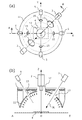
図1は、本発明の第1実施形態に係る検査装置の構成を模式的に示す図である。図1(a)は、Z軸天頂側から照明装置と投影装置の配置を表した図であり、図1(b)は、図1(a)のAOB線(一点鎖線)における組み合わせ断面図である。
<First Embodiment>
FIG. 1 is a diagram schematically showing the configuration of the inspection apparatus according to the first embodiment of the present invention. Fig.1 (a) is a figure showing arrangement | positioning of an illuminating device and a projection apparatus from the Z-axis zenith side, FIG.1 (b) is a combined sectional view in the AOB line (dashed-dotted line) of Fig.1 (a). is there.
検査装置は、照明装置1と、カメラ2と、投影装置3と、処理装置Pと、搬送装置(不図示)を有している。照明装置1は、はんだ形状計測用の照明であって、天頂角に応じて色が段階的若しくは連続的に変化する照明光を全方位から基板4に対し照射可能に構成されている。投影装置3は、拡散物体計測用の照明であって、Z軸に対し斜めの方向(例えば天頂角=約30度の方向)から、パタン光3Lを基板4に対し投影可能に構成されている。カメラ2は、その光軸がZ軸に一致するように配置され、垂直方向から基板4を撮影するカラーカメラであり、はんだ形状計測用の画像撮影と拡散物体計測用の画像撮影の両方に利用される。処理装置Pは、照明装置、投影装置、カメラ、搬送装置などの制御、カメラで撮影された画像の解析、はんだ接合の検査、部品高さの計測、検査結果の出力などの処理を担う装置である。搬送装置は、検査対象となる基板4を搬送するための装置であり、本実施形態では、X軸の負側より基板4を搬入し、検査を終えた基板4をX軸の正側へと搬出する(図10参照)。
The inspection device includes an
本実施形態の照明装置1は、青色LED10B、緑色LED10G、赤色LED10Rが同心円状に配列された光源基板と、ドーム形状の拡散板11とから構成されたドーム状照明装置である。照明装置1の天頂部には開口12が設けられており、カメラ2はこの開口12を通して基板4を真上から撮影可能に設置される。また、照明装置1の中腹、検査位置Oから見て約45度の方位と約225度の方位には、投影装置用の開口13が形成されている。これより、照明装置1の外側に設置された投影装置3から、各開口13を通してパタン光3Lを基板4に投影できるようになっている。
The illuminating
はんだ形状を計測する場合には、照明装置1を点灯し、拡散板11の発光領域11B、11G、11Rからそれぞれ青色光1G、緑色光1G、赤色光1Rを照射する。これにより、天頂角が大きくなるに従い青色、緑色、赤色と色が変化する照明光が全方位から基板4に対し照射される(つまり、ある天頂角φに対応する同じ色の光が、方位角θ=0〜360度の全ての方位から、基板4に入射する)。この照明下で基板4を撮影すると、はんだ部分の画像には傾斜角に応じた色相が現れる。よって、色相の変化を解析することで、はんだフィレットの3次元形状(ぬれ上がり高さ)などを推定することができる。
When measuring the solder shape, the
拡散物体の計測には、例えば、位相シフト、光切断法などの方法を利用することができ
る。位相シフトの場合には、投影装置3から縞状のパタン光を投影した状態で基板4を撮影する操作を、縞状パタンの周期を変化させながら複数回行い、縞状パタンの位相の変化に基づき拡散物体の3次元形状(部品高さなど)を推定する。また、光切断法の場合には、ライン状のパタン光を投影し、パタン光の変形により拡散物体の3次元形状を推定する。なお、投影装置3から投影するパタン光は、縞状やライン状のパタン光に限られず、所定の模様や形状をもつように形成された光であればどのようなものでもよい。
For example, a method such as a phase shift or a light cutting method can be used for measuring the diffuse object. In the case of the phase shift, the operation of photographing the
本実施形態の検査装置の利点について説明する。図10は、基板表面を上側からみた平面図であり、図10の右方向に基板4が搬送されるものとする。図10に示すように、基板4に表面実装される部品のほとんどは、基板4の縦方向又は横方向に平行に配列される。そのため、はんだフィレットの傾斜面は概ねX軸方向かY軸方向を向くように形成されることとなる。この点、本実施形態では、投影装置用の開口13をX軸方向とY軸方向のいずれとも異なる方位に設けているため、図1(b)のAO断面に示すように、X軸正方向(0度)、X軸負方向(180度)、Y軸正方向(90度)、Y軸負方向(270度)の四つの方位では、最小の天頂角φmin(本実施形態では青色発光領域11Bの上端の天頂角)から最大の天頂角φmax(本実施形態では赤色発光領域11Rの下端の天頂角)まで発光領域が連続し、照明光の抜けが無い。したがって、投影装置用の開口13による照明光の抜けがはんだ形状の計測に与え得る影響を十分に小さくでき、安定した形状計測を実現できる。
Advantages of the inspection apparatus of this embodiment will be described. FIG. 10 is a plan view of the substrate surface as viewed from above, and the
なお、開口13の方位がX軸方向(0度又は180度)とY軸方向(90度又は270度)のいずれとも異なっていさえすれば、開口13による影響を低減する効果は得られるが、本実施形態のように、X軸方向とY軸方向のいずれからも最も遠い方位である45度+n×90度(n=0,1,2,3)の近辺に配置するのが、開口13による影響を最小限にできるため最も好ましい。
As long as the orientation of the
また開口13を45度+n×90度の近辺に配置すると、検査位置から見て対角に(180度異なる方位に)配置した2台の投影装置3だけで、基板上の計測対象の略全体をカバーできるという利点もある。すなわち、本実施形態のように約45度と約225度に開口13を設けた場合であれば、約45度から投影したパタン光により、部品の上面とX軸正方向側の面とY軸正方向側の面の三つの面を照らすことができ、約225度から投影したパタン光により、部品の上面とX軸負方向側の面とY軸負方向側の面の三つの面を照らすことができるため、従来装置(図12参照)のようにX軸方向の左右に2台の投影装置103を設置した場合よりも、死角(パタン光が届かない部分)を減らすことができる。
Further, when the
<第2実施形態>
図2は、本発明の第2実施形態に係る検査装置の構成を模式的に示す図である。第1実施形態との違いは、投影装置3を四つ設置し、投影装置用の開口13を約45度、約135度、約225度、約315度の四つの方位に設けた点である。かかる構成によっても第1実施形態と同様の作用効果を得ることができる。
Second Embodiment
FIG. 2 is a diagram schematically showing the configuration of the inspection apparatus according to the second embodiment of the present invention. The difference from the first embodiment is that four
<第3実施形態>
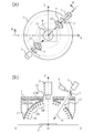
図3は、本発明の第3実施形態に係る検査装置の構成を模式的に示す図である。図3(a)は、Z軸天頂側から照明装置と投影装置と斜視カメラの配置を表した図であり、図3(b)は、図3(a)のAOB線(一点鎖線)における組み合わせ断面図である。以下、第1実施形態との相違部分についてのみ説明する。
<Third Embodiment>
FIG. 3 is a diagram schematically showing the configuration of the inspection apparatus according to the third embodiment of the present invention. FIG. 3A is a diagram showing the arrangement of the illumination device, the projection device, and the perspective camera from the Z-axis zenith side, and FIG. 3B is a combination of the AOB lines (dashed lines) in FIG. It is sectional drawing. Only differences from the first embodiment will be described below.
検査装置は、第1実施形態の構成に加え、4台の斜視カメラ5を有している。斜視カメラ5は、Z軸に対して斜めの方向から基板4を撮影するためのカメラである。斜視カメラ5は、真上からでは観測が困難な構造(例えば、Jリード等のフィレットやブリッジ)を
検査する目的や、ステレオ撮影による3次元計測の目的などに利用可能である。斜視カメラ5も、投影装置3と同じく基板4に対し斜めに設置する必要があるため、本実施形態では照明装置1の中腹に斜視カメラ用の開口15を設けている。このとき、投影装置用の開口13と斜視カメラ用の開口15とが異なる方位になるように配置を工夫している。その理由は、2つの開口13、15を同じ方位に縦に並べて設けた場合、その方位における照明光の抜けが極めて大きくなり、はんだ形状の計測精度が著しく低下するおそれがあるからである。具体的に本実施形態では、投影装置用の二つの開口13を約45度と約225度の方位に配置し、斜視カメラ用の四つの開口15を約0度、約90度、約180度、約270度の方位に配置することとした。
The inspection apparatus includes four
以上述べた本実施形態の構成によっても、第1実施形態と同様の作用効果を得ることができる。なお、本実施形態の構成では、X軸方向やY軸方向において開口15による照明光の抜けが生じるが、図から分かるように、斜視カメラ用の開口15は投影装置用の開口13に比べてサイズを小さくできるため、(従来のように投影装置用の開口をX軸方向やY軸方向に配置するのと比較して)開口15による影響はさほど問題とならない。
Also with the configuration of the present embodiment described above, the same effects as those of the first embodiment can be obtained. In the configuration of the present embodiment, the illumination light is lost due to the
<第4実施形態>
図4は、本発明の第5実施形態に係る検査装置の構成を模式的に示す図である。第3実施形態との違いは、斜視カメラ5を二つにし、斜視カメラ用の開口15を約135度と約315度の二つの方位に設けた点である。この構成によれば、X軸方向及びY軸方向における照明光の抜けを無くすことができるので、第3実施形態よりもはんだ形状計測の信頼性を向上することができる。
<Fourth embodiment>
FIG. 4 is a diagram schematically showing the configuration of the inspection apparatus according to the fifth embodiment of the present invention. The difference from the third embodiment is that the number of the
<第5実施形態>
図5は、本発明の第5実施形態に係る検査装置の構成を模式的に示す図である。第5実施形態は、第1実施形態又は第2実施形態の変形例であり、その違いは、各投影装置3に対し補完照明装置6と光学部材7を組み合わせた点である。
<Fifth Embodiment>
FIG. 5 is a diagram schematically showing a configuration of an inspection apparatus according to the fifth embodiment of the present invention. The fifth embodiment is a modification of the first embodiment or the second embodiment, and the difference is that the
補完照明装置6は、投影装置用の開口13による照明光の欠損を補うための補完光6Gを照射する照明である。本実施形態では、投影装置用の開口13が緑色光1Gの領域に形成されているため、緑色の補完光6Gを発する緑色LEDにより補完照明装置6が形成される。光学部材7は、補完照明装置6の光軸と投影装置3の光軸とを一致させるための光学系であり、例えばハーフミラーを用いることができる。
The
はんだ形状を計測する際、照明装置1と補完照明装置6の両方を点灯することで、開口13を通して補完光6Gが基板4に照射されるため、実質的に開口13が無いのと同じ照明状態を実現することができる。したがって、本実施形態によれば、前述した実施形態よりもさらにはんだ形状計測の信頼性を向上することができる。
When the solder shape is measured, since both the
<第6実施形態>
図6は、本発明の第6実施形態に係る検査装置の構成を模式的に示す図である。第6実施形態は、第3実施形態の変形例であり、その違いは、各投影装置3に対し補完照明装置6と光学部材7を組み合わせた点と各斜視カメラ5に対し補完照明装置8と光学部材9を組み合わせた点である。投影装置用の補完照明装置6及び光学部材7は第5実施形態のものと同様のため説明を省略する。
<Sixth Embodiment>
FIG. 6 is a diagram schematically showing the configuration of the inspection apparatus according to the sixth embodiment of the present invention. The sixth embodiment is a modification of the third embodiment, the difference being that each
補完照明装置8は、斜視カメラ用の開口15による照明光の欠損を補うための補完光8Gを照射する照明である。本実施形態では、斜視カメラ用の開口15が緑色光1Gの領域に形成されているため、緑色の補完光8Gを発する緑色LEDにより補完照明装置8が形成される。光学部材9は、補完照明装置8の光軸と斜視カメラ5の光軸とを一致させるた
めの光学系であり、例えばハーフミラーを用いることができる。
The
はんだ形状を計測する際、照明装置1と補完照明装置6と補完照明装置8を点灯することで、開口13と15を通して補完光6Gと8Gが基板4に照射されるため、実質的に開口13、15が無いのと同じ照明状態を実現することができる。したがって、本実施形態によれば、前述した実施形態よりもさらにはんだ形状計測の信頼性を向上することができる。
When measuring the solder shape, the
<第7実施形態>
図7は、本発明の第7実施形態に係る検査装置の構成を模式的に示す図である。第7実施形態では、投影装置3と斜視カメラ5を1ユニットにした点が特徴である。
図7(b)に示すように、ハーフミラー等の光学部材7によって投影装置3の光軸と斜視カメラ5の光軸を一致させ、投影装置用の開口13が斜視カメラ用の開口も兼ねている。このように投影装置3と斜視カメラ5で開口を共通にしたことで、照明装置1に設けるべき開口の数(面積)を前述の実施形態よりも減らすことができる。したがって、開口による照明光の抜けを小さくでき、はんだ形状計測の信頼性を向上することができる。
<Seventh embodiment>
FIG. 7 is a diagram schematically showing a configuration of an inspection apparatus according to the seventh embodiment of the present invention. The seventh embodiment is characterized in that the
As shown in FIG. 7B, the optical axis of the
<第8実施形態>
図8は、本発明の第8実施形態に係る検査装置の構成を模式的に示す図である。第8実施形態は、第7実施形態の変形例であり、その違いは、投影装置3と斜視カメラ5のユニットをX軸正方向、X軸負方向、Y軸正方向、Y軸負方向それぞれに配置した点である。
本実施形態の構成によっても、第7実施形態と同様の作用効果を得ることができる。なお、本実施形態の構成では、X軸方向やY軸方向において開口13による照明光の抜けが生じるが、一つの開口13が投影装置用の開口と斜視カメラ用の開口を兼ねているため、(投影装置用の開口と斜視カメラ用の開口を別々に設ける構成と比較して)開口13による照明光の抜けの影響を低減できる効果が得られる。
<Eighth Embodiment>
FIG. 8 is a diagram schematically showing the configuration of the inspection apparatus according to the eighth embodiment of the present invention. The eighth embodiment is a modification of the seventh embodiment, the difference being that the units of the
Also according to the configuration of the present embodiment, the same effects as those of the seventh embodiment can be obtained. In the configuration of the present embodiment, illumination light is lost due to the
<第9実施形態>
図9は、本発明の第9実施形態に係る検査装置の構成を模式的に示す図である。前述した実施形態では、ドーム状照明装置1を用いていたのに対し、本実施形態では、色が異なる複数の発光体20B,20G,20Rから構成された照明装置20を用いている点が異なる。
<Ninth Embodiment>
FIG. 9 is a diagram schematically showing the configuration of the inspection apparatus according to the ninth embodiment of the present invention. In the above-described embodiment, the dome-shaped
発光体20Bは、青色光を発する環状照明であり、例えば、環状基板に青色LEDを配列することで作製することができる。発光体20Gは、緑色光を発する環状照明であり、発光体20Rは、赤色光を発する環状照明であり、それぞれ発光体20Bと同じように作製可能である。三つの発光体20B、20G、20Rを天頂角を変えて配置することで、前述したドーム状照明装置1と同様の照明光を照射することができる。
The
本実施形態においては、照明装置20の外側に配置した投影装置3から基板4へパタン光を投影するため、発光体20Gの一部に投影装置用の開口13を形成している。このときも、開口13の方位をX軸方向とY軸方向のいずれとも異ならせることで、第1実施形態で述べたのと同様の作用効果を得ることができる。なお、照明光の抜けを極力少なくし、はんだ形状計測の信頼性を高めるため、開口13以外の部分では発光体同士を略隙間なく並べる(隙間を無くすか、はんだ形状の計測に影響を及ぼさない程度の十分に小さい隙間とする)とよい。
In the present embodiment, the
<その他>
上記の実施形態の説明は、本発明を例示的に説明するものに過ぎず、本発明は上記の具体的な形態には限定されない。本発明は、その技術的思想の範囲内で種々の変形が可能で
ある。
例えば、各々の実施形態の構成は、技術的な矛盾が生じない限り、互いに組み合わせることもできる。また、第1実施形態や第2実施形態の投影装置3を斜視カメラ5に置き換えた構成を採ることもできる。すなわち、照明装置1とカメラ2と斜視カメラ5を有する構成において、斜視カメラ用の開口をX軸方向やY軸方向とは異なる方位に設けるのである。
また、はんだ形状計測用の照明装置として、3色の照明を用いたが、2色又は4色以上の照明を用いることもできる。また、段階的に色が変化する照明ではなく、連続的に色が変化する照明を用いてもよい。あるいは、色でなく、輝度が段階的又は連続的に変化する照明を用いることも可能である。
<Others>
The description of the above embodiment is merely illustrative of the present invention, and the present invention is not limited to the above specific form. The present invention can be variously modified within the scope of its technical idea.
For example, the configurations of the embodiments can be combined with each other as long as there is no technical contradiction. Moreover, the structure which replaced the
Moreover, although the illumination of 3 colors was used as an illuminating device for solder shape measurement, illumination of 2 colors or 4 colors or more can also be used. Moreover, you may use the illumination from which a color changes continuously instead of the illumination from which a color changes in steps. Alternatively, it is also possible to use illumination in which the luminance changes stepwise or continuously instead of color.
1:照明装置
1R:赤色光、1G:緑色光、1B:青色光
10R:赤色LED、10G:緑色LED、10B:青色LED
11:拡散板、11R,11G,11B:発光領域
2:カメラ、12:カメラ用の開口
3:投影装置、3L:パタン光、13:投影装置用の開口
4:基板
5:斜視カメラ、15:斜視カメラ用の開口
6:補完照明装置、6G:補完光
7:光学部材
8:補完照明装置、8G:補完光
9:光学部材
20:照明装置
20R,20G,20B:発光体
O:検査位置
P:処理装置
1:
11: Diffuser plate, 11R, 11G, 11B: Light emitting area 2: Camera, 12: Camera opening 3: Projection device, 3L: Pattern light, 13: Projection device opening 4: Substrate 5: Perspective camera, 15: Perspective camera opening 6: complementary illumination device, 6G: complementary light 7: optical member 8: complementary illumination device, 8G: complementary light 9: optical member 20:
Claims (9)
検査装置内に搬送された基板と前記カメラの光軸との交点を原点とし、基板表面に平行で且つ基板の搬送方向に平行にX軸、基板表面に平行で且つ基板の搬送方向に垂直にY軸、基板表面に垂直にZ軸をとり、Z軸となす角を天頂角、原点から見たXY面内における方向を方位という場合に、
天頂角に応じて色又は輝度が段階的若しくは連続的に変化する照明光を全方位から基板に対し照射可能に構成された照明装置と、
Z軸に対し斜めの方向から、パタン光を基板に対し投影可能に構成された一つ又は複数の投影装置と、
前記照明装置を点灯した状態、又は、前記投影装置から前記パタン光を投影した状態で前記カメラにより撮影された基板の画像を用いて検査を行う処理装置と、を有し、
前記投影装置は、前記照明装置に設けられた開口を通して、パタン光を基板に対し投影するものであり、
前記開口は、原点から見て、X軸方向とY軸方向のいずれとも異なる方位に設けられている
ことを特徴とする検査装置。 An inspection apparatus having a camera for photographing a board on which a component is soldered from a vertical direction,
The intersection between the substrate transported into the inspection apparatus and the optical axis of the camera is the origin, parallel to the substrate surface and parallel to the substrate transport direction, X-axis, parallel to the substrate surface and perpendicular to the substrate transport direction When the Y axis is the Z axis perpendicular to the substrate surface, the angle formed with the Z axis is the zenith angle, and the direction in the XY plane as viewed from the origin is the orientation,
An illumination device configured to irradiate the substrate with illumination light whose color or brightness changes stepwise or continuously according to the zenith angle from all directions;
One or a plurality of projection devices configured to project pattern light onto the substrate from a direction oblique to the Z axis;
A processing device that performs inspection using an image of a substrate photographed by the camera in a state in which the illumination device is turned on or in a state in which the pattern light is projected from the projection device;
The projection device projects pattern light onto a substrate through an opening provided in the illumination device.
The inspection apparatus is characterized in that the opening is provided in an azimuth different from both the X-axis direction and the Y-axis direction when viewed from the origin.
少なくともX軸正方向、X軸負方向、Y軸正方向、Y軸負方向の四つの方位では、最小の天頂角から最大の天頂角まで前記発光領域が連続している
ことを特徴とする請求項1に記載の検査装置。 The lighting device is a lighting device having a dome-shaped light emitting region,
The light emitting region is continuous from a minimum zenith angle to a maximum zenith angle in at least four directions of X axis positive direction, X axis negative direction, Y axis positive direction, and Y axis negative direction. Item 2. The inspection apparatus according to Item 1.
少なくともX軸正方向、X軸負方向、Y軸正方向、Y軸負方向の四つの方位では、前記複数の発光体が略隙間なく並べられている
ことを特徴とする請求項1に記載の検査装置。 The lighting device is a lighting device in which a plurality of light emitters having different colors or brightness are arranged with different zenith angles,
The plurality of light emitters are arranged with substantially no gap in at least four directions of an X-axis positive direction, an X-axis negative direction, a Y-axis positive direction, and a Y-axis negative direction. Inspection device.
前記開口は、原点から見て、約45度、約135度、約225度、約315度のうちのいずれかの方位に設けられている
ことを特徴とする請求項1〜3のうちいずれか1項に記載の検査装置。 When the azimuth angle in the X-axis positive direction is 0 degree,
The opening is provided in any one of about 45 degrees, about 135 degrees, about 225 degrees, and about 315 degrees as viewed from the origin. The inspection apparatus according to item 1.
一方の投影装置用の開口と他方の投影装置用の開口とが、原点から見て、180度異なる方位に設けられている
ことを特徴とする請求項1〜4のうちいずれか1項に記載の検査装置。 Has two projection devices,
The opening for one projection apparatus and the opening for the other projection apparatus are provided in directions different from each other by 180 degrees when viewed from the origin. Inspection equipment.
ことを特徴とする請求項1〜5のうちいずれか1項に記載の検査装置。 6. The camera according to claim 1, further comprising one or a plurality of perspective cameras for photographing the substrate from a direction oblique to the Z axis through an opening provided in the illumination device. The inspection device described in 1.
ことを特徴とする請求項6に記載の検査装置。 The inspection apparatus according to claim 6, wherein the opening for the projection device and the opening for the perspective camera are provided in different directions as viewed from the origin.
前記投影装置用の開口が前記斜視カメラ用の開口を兼ねている
ことを特徴とする請求項6に記載の検査装置。 An optical member that matches the optical axis of the projection device and the optical axis of the perspective camera;
The inspection apparatus according to claim 6, wherein the opening for the projection device also serves as the opening for the perspective camera.
ことを特徴とする請求項1〜8のうちいずれか1項に記載の検査装置。 The inspection according to any one of claims 1 to 8, further comprising a complementary illumination device that irradiates the substrate with complementary light that compensates for a loss of illumination light due to an opening provided in the illumination device. apparatus.
Priority Applications (4)
| Application Number | Priority Date | Filing Date | Title |
|---|---|---|---|
| JP2014043754A JP6287360B2 (en) | 2014-03-06 | 2014-03-06 | Inspection device |
| CN201510082233.5A CN104897691B (en) | 2014-03-06 | 2015-02-15 | Check device |
| DE102015202954.9A DE102015202954A1 (en) | 2014-03-06 | 2015-02-18 | Tester |
| US14/626,971 US20150253129A1 (en) | 2014-03-06 | 2015-02-20 | Inspection apparatus |
Applications Claiming Priority (1)
| Application Number | Priority Date | Filing Date | Title |
|---|---|---|---|
| JP2014043754A JP6287360B2 (en) | 2014-03-06 | 2014-03-06 | Inspection device |
Publications (2)
| Publication Number | Publication Date |
|---|---|
| JP2015169510A JP2015169510A (en) | 2015-09-28 |
| JP6287360B2 true JP6287360B2 (en) | 2018-03-07 |
Family
ID=53884164
Family Applications (1)
| Application Number | Title | Priority Date | Filing Date |
|---|---|---|---|
| JP2014043754A Active JP6287360B2 (en) | 2014-03-06 | 2014-03-06 | Inspection device |
Country Status (4)
| Country | Link |
|---|---|
| US (1) | US20150253129A1 (en) |
| JP (1) | JP6287360B2 (en) |
| CN (1) | CN104897691B (en) |
| DE (1) | DE102015202954A1 (en) |
Families Citing this family (21)
| Publication number | Priority date | Publication date | Assignee | Title |
|---|---|---|---|---|
| JP5900037B2 (en) * | 2012-03-08 | 2016-04-06 | オムロン株式会社 | Image processing apparatus and control method thereof |
| EP3140639A4 (en) * | 2014-05-05 | 2018-01-31 | Arconic Inc. | Apparatus and methods for weld measurement |
| JP2017120232A (en) * | 2015-12-28 | 2017-07-06 | キヤノン株式会社 | Inspection device |
| FR3049709B1 (en) * | 2016-04-05 | 2019-08-30 | Areva Np | METHOD OF DETECTING A DEFECT ON A SURFACE BY MULTIDIRECTIONAL LIGHTING AND ASSOCIATED DEVICE |
| KR101739696B1 (en) * | 2016-07-13 | 2017-05-25 | 서장일 | Lighting system of recognizing material of an object and method of recognizing material of an object using the same |
| JP6912824B2 (en) * | 2016-11-09 | 2021-08-04 | 株式会社ブイ・テクノロジー | Optical inspection equipment |
| JP7143740B2 (en) * | 2018-02-07 | 2022-09-29 | オムロン株式会社 | Image inspection equipment and lighting equipment |
| EP3524967B1 (en) * | 2018-02-07 | 2024-01-31 | OMRON Corporation | Image inspection device and lighting device |
| KR102090006B1 (en) * | 2018-08-06 | 2020-03-17 | 주식회사 디딤센서 | Illumination system |
| JP7445994B2 (en) * | 2019-01-14 | 2024-03-08 | エイジーアール インターナショナル,インコーポレイテッド | Method and apparatus for inspecting liquid-filled hollow transparent articles |
| JP7231433B2 (en) * | 2019-02-15 | 2023-03-01 | 株式会社キーエンス | Image processing device |
| DE102019107174B4 (en) * | 2019-03-20 | 2020-12-24 | Thyssenkrupp Rasselstein Gmbh | Method and apparatus for inspecting the surface of a moving belt |
| JP7140732B2 (en) * | 2019-09-20 | 2022-09-21 | 矢崎総業株式会社 | Appearance inspection device for crimp terminals |
| JP7395950B2 (en) * | 2019-10-23 | 2023-12-12 | オムロン株式会社 | Visual inspection equipment and visual inspection method |
| US11442427B2 (en) | 2019-12-25 | 2022-09-13 | National Chung-Shan Institute Of Science And Technology | Multiaxis machining device and compensation method thereof |
| JP6830997B1 (en) * | 2019-12-26 | 2021-02-17 | 國家中山科學研究院 | Multi-axis machining equipment and its compensation method |
| JP7452188B2 (en) | 2020-03-30 | 2024-03-19 | オムロン株式会社 | Inspection equipment |
| CN111487251A (en) * | 2020-04-27 | 2020-08-04 | 中国科学院长春光学精密机械与物理研究所 | AOI imaging component system and using method thereof |
| KR20230097145A (en) * | 2020-11-30 | 2023-06-30 | 야마하하쓰도키 가부시키가이샤 | Mounted board inspection device and inspection device |
| CN113820331A (en) * | 2021-09-06 | 2021-12-21 | 深圳格兰达智能装备股份有限公司 | Three-dimensional defect detection device |
| WO2023033627A1 (en) * | 2021-09-06 | 2023-03-09 | 삼성전자 주식회사 | Optical system including dome light and coaxial light and method for designing optical system |
Family Cites Families (29)
| Publication number | Priority date | Publication date | Assignee | Title |
|---|---|---|---|---|
| US4736826A (en) * | 1985-04-22 | 1988-04-12 | Remote Technology Corporation | Remotely controlled and/or powered mobile robot with cable management arrangement |
| JPH05231837A (en) * | 1991-12-25 | 1993-09-07 | Toshiba Corp | Method and device for measuring shape |
| US6512385B1 (en) * | 1999-07-26 | 2003-01-28 | Paul Pfaff | Method for testing a device under test including the interference of two beams |
| JP4038993B2 (en) * | 2001-03-29 | 2008-01-30 | オムロン株式会社 | Illumination device for curved surface property inspection device |
| US7526120B2 (en) * | 2002-09-11 | 2009-04-28 | Canesta, Inc. | System and method for providing intelligent airbag deployment |
| JP4166587B2 (en) * | 2003-01-24 | 2008-10-15 | 株式会社サキコーポレーション | Appearance inspection apparatus and volume inspection method |
| US20040184653A1 (en) * | 2003-03-20 | 2004-09-23 | Baer Richard L. | Optical inspection system, illumination apparatus and method for use in imaging specular objects based on illumination gradients |
| WO2006120759A1 (en) * | 2005-05-12 | 2006-11-16 | Techno Dream 21 Co., Ltd. | 3-dimensional shape measuring method and device thereof |
| EP2281668B1 (en) * | 2005-09-30 | 2013-04-17 | iRobot Corporation | Companion robot for personal interaction |
| JP4917615B2 (en) * | 2006-02-27 | 2012-04-18 | プライム センス リミティド | Range mapping using uncorrelated speckle |
| US7719222B2 (en) * | 2006-03-30 | 2010-05-18 | Vecna Technologies, Inc. | Mobile extraction-assist robot |
| US8050486B2 (en) * | 2006-05-16 | 2011-11-01 | The Boeing Company | System and method for identifying a feature of a workpiece |
| US20080256008A1 (en) * | 2007-03-31 | 2008-10-16 | Mitchell Kwok | Human Artificial Intelligence Machine |
| IL184868A0 (en) * | 2007-07-26 | 2008-03-20 | Univ Bar Ilan | Motion detection system and method |
| JP4389982B2 (en) * | 2007-08-09 | 2009-12-24 | オムロン株式会社 | Substrate visual inspection device |
| JP5084398B2 (en) * | 2007-08-24 | 2012-11-28 | キヤノン株式会社 | Measuring apparatus, measuring method, and program |
| WO2009062162A1 (en) * | 2007-11-09 | 2009-05-14 | Cidra Corporate Services, Inc. | Non-contact optical flow measurements |
| TWI356357B (en) * | 2007-12-24 | 2012-01-11 | Univ Nat Chiao Tung | A method for estimating a body pose |
| TW200933538A (en) * | 2008-01-31 | 2009-08-01 | Univ Nat Chiao Tung | Nursing system |
| JP5198189B2 (en) * | 2008-08-29 | 2013-05-15 | 富士フイルム株式会社 | Hard disk inspection device |
| DE102010029091B4 (en) * | 2009-05-21 | 2015-08-20 | Koh Young Technology Inc. | Form measuring device and method |
| DE102010030883B4 (en) * | 2009-07-03 | 2018-11-08 | Koh Young Technology Inc. | Apparatus for testing a plate and method therefor |
| JP5566707B2 (en) * | 2010-01-19 | 2014-08-06 | 株式会社サキコーポレーション | Appearance inspection apparatus and appearance inspection method |
| JP5170154B2 (en) * | 2010-04-26 | 2013-03-27 | オムロン株式会社 | Shape measuring apparatus and calibration method |
| JP5443303B2 (en) * | 2010-09-03 | 2014-03-19 | 株式会社サキコーポレーション | Appearance inspection apparatus and appearance inspection method |
| US8334985B2 (en) * | 2010-10-08 | 2012-12-18 | Omron Corporation | Shape measuring apparatus and shape measuring method |
| WO2013133286A1 (en) * | 2012-03-06 | 2013-09-12 | 株式会社ニコン | Shape-measurement device, system for manufacturing structural object, scanning device, method for measuring shape, method for manufacturing structural object, and shape-measurement program |
| JP5874508B2 (en) * | 2012-04-17 | 2016-03-02 | オムロン株式会社 | Solder wetting state inspection method, automatic visual inspection apparatus and board inspection system using this method |
| TWI460394B (en) * | 2012-07-20 | 2014-11-11 | Test Research Inc | Three-dimensional image measuring apparatus |
-
2014
- 2014-03-06 JP JP2014043754A patent/JP6287360B2/en active Active
-
2015
- 2015-02-15 CN CN201510082233.5A patent/CN104897691B/en active Active
- 2015-02-18 DE DE102015202954.9A patent/DE102015202954A1/en active Pending
- 2015-02-20 US US14/626,971 patent/US20150253129A1/en not_active Abandoned
Also Published As
| Publication number | Publication date |
|---|---|
| CN104897691A (en) | 2015-09-09 |
| DE102015202954A1 (en) | 2015-09-10 |
| CN104897691B (en) | 2017-11-14 |
| JP2015169510A (en) | 2015-09-28 |
| US20150253129A1 (en) | 2015-09-10 |
Similar Documents
| Publication | Publication Date | Title |
|---|---|---|
| JP6287360B2 (en) | Inspection device | |
| KR101207198B1 (en) | Board inspection apparatus | |
| TW201205033A (en) | Shape measuring device and calibrating method | |
| KR101241175B1 (en) | Mounting boards inspection apparatus and method thereof | |
| US20140232850A1 (en) | Vision testing device with enhanced image clarity | |
| JP2014508938A (en) | Vision inspection equipment using multiple grid patterns | |
| TWI626699B (en) | Vision inspection device | |
| JP2004191355A5 (en) | ||
| JP5945386B2 (en) | Printed solder inspection equipment | |
| JP6791631B2 (en) | Image generation method and inspection equipment | |
| KR20180013709A (en) | Lighting unit, defects inspection device, and lighting method | |
| JP7187782B2 (en) | Image inspection equipment | |
| JP2012018082A (en) | Board inspection device | |
| JP2007294576A (en) | Testing apparatus and testing method | |
| JP2009294115A (en) | Three-dimensional measurement display method | |
| KR101114251B1 (en) | 3d surface imaging system | |
| WO2021199513A1 (en) | Inspection device | |
| JP6067407B2 (en) | Inspection device | |
| JP2012169370A (en) | Display panel inspection equipment and display panel inspection method | |
| JP7143740B2 (en) | Image inspection equipment and lighting equipment | |
| WO2020262593A1 (en) | Appearance inspection apparatus and appearance inspection method | |
| JPH0625713U (en) | Soldering part inspection device | |
| JP5541646B2 (en) | Line lighting device | |
| CN110383001B (en) | Appearance inspection device and appearance inspection method | |
| WO2021153057A1 (en) | Three-dimensional shape measurement device, three-dimensional shape measurement method, and program |
Legal Events
| Date | Code | Title | Description |
|---|---|---|---|
| A621 | Written request for application examination |
Free format text: JAPANESE INTERMEDIATE CODE: A621 Effective date: 20161213 |
|
| A131 | Notification of reasons for refusal |
Free format text: JAPANESE INTERMEDIATE CODE: A131 Effective date: 20170822 |
|
| A977 | Report on retrieval |
Free format text: JAPANESE INTERMEDIATE CODE: A971007 Effective date: 20170823 |
|
| A521 | Request for written amendment filed |
Free format text: JAPANESE INTERMEDIATE CODE: A523 Effective date: 20171011 |
|
| TRDD | Decision of grant or rejection written | ||
| A01 | Written decision to grant a patent or to grant a registration (utility model) |
Free format text: JAPANESE INTERMEDIATE CODE: A01 Effective date: 20180109 |
|
| A61 | First payment of annual fees (during grant procedure) |
Free format text: JAPANESE INTERMEDIATE CODE: A61 Effective date: 20180122 |
|
| R150 | Certificate of patent or registration of utility model |
Ref document number: 6287360 Country of ref document: JP Free format text: JAPANESE INTERMEDIATE CODE: R150 |