JP6270325B2 - Information processing apparatus and control method thereof - Google Patents
Information processing apparatus and control method thereof Download PDFInfo
- Publication number
- JP6270325B2 JP6270325B2 JP2013053600A JP2013053600A JP6270325B2 JP 6270325 B2 JP6270325 B2 JP 6270325B2 JP 2013053600 A JP2013053600 A JP 2013053600A JP 2013053600 A JP2013053600 A JP 2013053600A JP 6270325 B2 JP6270325 B2 JP 6270325B2
- Authority
- JP
- Japan
- Prior art keywords
- information processing
- processing apparatus
- image
- information
- area
- Prior art date
- Legal status (The legal status is an assumption and is not a legal conclusion. Google has not performed a legal analysis and makes no representation as to the accuracy of the status listed.)
- Expired - Fee Related
Links
Images


Classifications
-
- G—PHYSICS
- G06—COMPUTING; CALCULATING OR COUNTING
- G06Q—INFORMATION AND COMMUNICATION TECHNOLOGY [ICT] SPECIALLY ADAPTED FOR ADMINISTRATIVE, COMMERCIAL, FINANCIAL, MANAGERIAL OR SUPERVISORY PURPOSES; SYSTEMS OR METHODS SPECIALLY ADAPTED FOR ADMINISTRATIVE, COMMERCIAL, FINANCIAL, MANAGERIAL OR SUPERVISORY PURPOSES, NOT OTHERWISE PROVIDED FOR
- G06Q10/00—Administration; Management
- G06Q10/10—Office automation; Time management
- G06Q10/107—Computer-aided management of electronic mailing [e-mailing]
-
- H—ELECTRICITY
- H04—ELECTRIC COMMUNICATION TECHNIQUE
- H04L—TRANSMISSION OF DIGITAL INFORMATION, e.g. TELEGRAPHIC COMMUNICATION
- H04L51/00—User-to-user messaging in packet-switching networks, transmitted according to store-and-forward or real-time protocols, e.g. e-mail
- H04L51/07—User-to-user messaging in packet-switching networks, transmitted according to store-and-forward or real-time protocols, e.g. e-mail characterised by the inclusion of specific contents
- H04L51/10—Multimedia information
-
- G—PHYSICS
- G06—COMPUTING; CALCULATING OR COUNTING
- G06F—ELECTRIC DIGITAL DATA PROCESSING
- G06F3/00—Input arrangements for transferring data to be processed into a form capable of being handled by the computer; Output arrangements for transferring data from processing unit to output unit, e.g. interface arrangements
- G06F3/01—Input arrangements or combined input and output arrangements for interaction between user and computer
- G06F3/03—Arrangements for converting the position or the displacement of a member into a coded form
- G06F3/041—Digitisers, e.g. for touch screens or touch pads, characterised by the transducing means
-
- G—PHYSICS
- G06—COMPUTING; CALCULATING OR COUNTING
- G06F—ELECTRIC DIGITAL DATA PROCESSING
- G06F3/00—Input arrangements for transferring data to be processed into a form capable of being handled by the computer; Output arrangements for transferring data from processing unit to output unit, e.g. interface arrangements
- G06F3/01—Input arrangements or combined input and output arrangements for interaction between user and computer
- G06F3/048—Interaction techniques based on graphical user interfaces [GUI]
- G06F3/0484—Interaction techniques based on graphical user interfaces [GUI] for the control of specific functions or operations, e.g. selecting or manipulating an object, an image or a displayed text element, setting a parameter value or selecting a range
- G06F3/04845—Interaction techniques based on graphical user interfaces [GUI] for the control of specific functions or operations, e.g. selecting or manipulating an object, an image or a displayed text element, setting a parameter value or selecting a range for image manipulation, e.g. dragging, rotation, expansion or change of colour
-
- H—ELECTRICITY
- H04—ELECTRIC COMMUNICATION TECHNIQUE
- H04N—PICTORIAL COMMUNICATION, e.g. TELEVISION
- H04N1/00—Scanning, transmission or reproduction of documents or the like, e.g. facsimile transmission; Details thereof
- H04N1/00095—Systems or arrangements for the transmission of the picture signal
- H04N1/00103—Systems or arrangements for the transmission of the picture signal specially adapted for radio transmission, e.g. via satellites
-
- H—ELECTRICITY
- H04—ELECTRIC COMMUNICATION TECHNIQUE
- H04N—PICTORIAL COMMUNICATION, e.g. TELEVISION
- H04N1/00—Scanning, transmission or reproduction of documents or the like, e.g. facsimile transmission; Details thereof
- H04N1/00127—Connection or combination of a still picture apparatus with another apparatus, e.g. for storage, processing or transmission of still picture signals or of information associated with a still picture
-
- H—ELECTRICITY
- H04—ELECTRIC COMMUNICATION TECHNIQUE
- H04N—PICTORIAL COMMUNICATION, e.g. TELEVISION
- H04N1/00—Scanning, transmission or reproduction of documents or the like, e.g. facsimile transmission; Details thereof
- H04N1/0035—User-machine interface; Control console
- H04N1/00405—Output means
- H04N1/00408—Display of information to the user, e.g. menus
- H04N1/00411—Display of information to the user, e.g. menus the display also being used for user input, e.g. touch screen
-
- H—ELECTRICITY
- H04—ELECTRIC COMMUNICATION TECHNIQUE
- H04N—PICTORIAL COMMUNICATION, e.g. TELEVISION
- H04N1/00—Scanning, transmission or reproduction of documents or the like, e.g. facsimile transmission; Details thereof
- H04N1/0035—User-machine interface; Control console
- H04N1/00405—Output means
- H04N1/00408—Display of information to the user, e.g. menus
- H04N1/0044—Display of information to the user, e.g. menus for image preview or review, e.g. to help the user position a sheet
- H04N1/00442—Simultaneous viewing of a plurality of images, e.g. using a mosaic display arrangement of thumbnails
- H04N1/00445—Simultaneous viewing of a plurality of images, e.g. using a mosaic display arrangement of thumbnails arranged in a one dimensional array
- H04N1/00448—Simultaneous viewing of a plurality of images, e.g. using a mosaic display arrangement of thumbnails arranged in a one dimensional array horizontally
-
- H—ELECTRICITY
- H04—ELECTRIC COMMUNICATION TECHNIQUE
- H04N—PICTORIAL COMMUNICATION, e.g. TELEVISION
- H04N2101/00—Still video cameras
-
- H—ELECTRICITY
- H04—ELECTRIC COMMUNICATION TECHNIQUE
- H04N—PICTORIAL COMMUNICATION, e.g. TELEVISION
- H04N2201/00—Indexing scheme relating to scanning, transmission or reproduction of documents or the like, and to details thereof
- H04N2201/0077—Types of the still picture apparatus
- H04N2201/0084—Digital still camera
-
- H—ELECTRICITY
- H04—ELECTRIC COMMUNICATION TECHNIQUE
- H04N—PICTORIAL COMMUNICATION, e.g. TELEVISION
- H04N2201/00—Indexing scheme relating to scanning, transmission or reproduction of documents or the like, and to details thereof
- H04N2201/32—Circuits or arrangements for control or supervision between transmitter and receiver or between image input and image output device, e.g. between a still-image camera and its memory or between a still-image camera and a printer device
- H04N2201/3201—Display, printing, storage or transmission of additional information, e.g. ID code, date and time or title
- H04N2201/3225—Display, printing, storage or transmission of additional information, e.g. ID code, date and time or title of data relating to an image, a page or a document
- H04N2201/3245—Display, printing, storage or transmission of additional information, e.g. ID code, date and time or title of data relating to an image, a page or a document of image modifying data, e.g. handwritten addenda, highlights or augmented reality information
-
- H—ELECTRICITY
- H04—ELECTRIC COMMUNICATION TECHNIQUE
- H04N—PICTORIAL COMMUNICATION, e.g. TELEVISION
- H04N2201/00—Indexing scheme relating to scanning, transmission or reproduction of documents or the like, and to details thereof
- H04N2201/32—Circuits or arrangements for control or supervision between transmitter and receiver or between image input and image output device, e.g. between a still-image camera and its memory or between a still-image camera and a printer device
- H04N2201/3201—Display, printing, storage or transmission of additional information, e.g. ID code, date and time or title
- H04N2201/3273—Display
-
- H—ELECTRICITY
- H04—ELECTRIC COMMUNICATION TECHNIQUE
- H04N—PICTORIAL COMMUNICATION, e.g. TELEVISION
- H04N23/00—Cameras or camera modules comprising electronic image sensors; Control thereof
- H04N23/60—Control of cameras or camera modules
- H04N23/62—Control of parameters via user interfaces
Description
本発明は、情報処理装置から他の情報処理装置に情報を送信させる技術に関する。 The present invention relates to a technique for transmitting information from an information processing apparatus to another information processing apparatus.
従来、情報機器に保存されたデータを、他の情報機器に送信する際には、当該他の情報機器で受信可能なメールアドレスに、送信したいデータを添付ファイルとしたメールを送信する方法が一般的に利用されていた。一般的に、メールでデータを送る場合には、情報機器に保存された複数のメールアドレスの中から目的のメールアドレスを特定し、データを添付したメールを作成する作業が必要である。 Conventionally, when data stored in an information device is transmitted to another information device, a method of transmitting an email with the data to be transmitted as an attached file to a mail address that can be received by the other information device is generally used. Was used. In general, when sending data by e-mail, it is necessary to identify a target e-mail address from among a plurality of e-mail addresses stored in an information device and create an e-mail with data attached.
特許文献1では、添付ファイルとして人物写真を選択すると、当該写真の被写体である人物のメールアドレスを送信先の候補として表示することか開示されている。 Patent Document 1 discloses that when a person photo is selected as an attached file, the mail address of the person who is the subject of the photo is displayed as a transmission destination candidate.
特許文献1によれば、人物に、その人物が被写体である写真を送る場合には、操作工程が削減される。送信先となる人物が写っていない写真や写真以外のデータをやり取りしたい場合には、依然として複数のメールアドレスの中から目的のメールアドレスを特定する作業が生じる。また、特定の人物にではなく表示装置に表示させるためや、印刷装置に印刷させるためにデータを送信したいような場合にも、送信先方法とアドレス情報を特定しなくてはならない。データを送信したい相手がすぐ近くに存在する場合、特許文献1によれば、相手を写真に撮ることで、メールアドレスの特定作業は簡略化できるが、送信したいデータとは異なる写真が添付されたメールを作成してしまうことになる。 According to Japanese Patent Application Laid-Open No. 2004-133620, when a photograph of the person as a subject is sent to a person, the operation process is reduced. When it is desired to exchange a photograph in which a person as a transmission destination is not shown or data other than a photograph, an operation for specifying a target mail address from among a plurality of mail addresses still occurs. In addition, even when it is desired to transmit data for display on a display device rather than for a specific person or for printing on a printing device, the transmission destination method and address information must be specified. According to Patent Document 1, when the person who wants to send data is in the immediate vicinity, taking a picture of the other person can simplify the work of identifying the e-mail address, but a photo different from the data to be sent is attached. You will create an email.
本発明は上記課題に鑑みてなされたものであり、近くに存在する相手や情報処理装置に対して情報を送信する際の操作性を向上させることを主な目的とする。 The present invention has been made in view of the above problems, and has as its main object to improve operability when transmitting information to a partner or an information processing apparatus existing nearby.
上記の目的を達成するために、本発明は、送信対象データを、他の情報処理装置に送信する情報処理装置であって、前記送信対象データの内容を視覚的に示すオブジェクト画像を、ライブビュー画像と共に表示画面に表示させる表示制御手段と、前記表示画面上で、前記オブジェクト画像のいずれかと、前記ライブビュー画像に被写体として含まれる人物のいずれかを並べて表示させて関連付ける関連付け操作を受け付ける受付手段と、前記受付手段に受け付けられた関連付け操作の対象となったオブジェクト画像に対応する送信対象データの送信先として、前記関連付け操作によって前記オブジェクト画像に関連付けられた人物に対応する他の情報処理装置を特定する特定手段と、を備えることを特徴とする。 In order to achieve the above object, the present invention provides an information processing apparatus for transmitting transmission target data to another information processing apparatus, wherein an object image visually showing the content of the transmission target data is displayed in a live view. Display control means for displaying on a display screen together with an image , and accepting means for accepting an association operation for displaying and associating one of the object images and a person included as a subject in the live view image on the display screen And another information processing apparatus corresponding to the person associated with the object image by the association operation as a transmission destination of the transmission target data corresponding to the object image that is the target of the association operation received by the reception unit. characterized in that it comprises a specifying means for specifying.
本発明によれば、極近くに存在する相手や情報処理装置に対して情報を送信する際の操作性を向上させることができる。 ADVANTAGE OF THE INVENTION According to this invention, the operativity at the time of transmitting information with respect to the other party and information processing apparatus which exist in the immediate vicinity can be improved.
以下、添付図面を参照して本発明に係る実施の形態を詳細に説明する。ただし、この実施の形態に記載されている構成要素はあくまでも例示であり、本発明の範囲をそれらのみに限定する趣旨のものではない。 Embodiments according to the present invention will be described below in detail with reference to the accompanying drawings. However, the constituent elements described in this embodiment are merely examples, and are not intended to limit the scope of the present invention only to them.
<実施形態1>
実施形態1では、カメラなどの撮像部を有する情報処理装置(自装置)において、撮像部でリアルタイムに撮像されている映像中で検出されている自装置以外の複数の情報処理装置(他装置)のうちの1つに、自装置に保存されているデータを送信する例を説明する。
<Embodiment 1>
In the first embodiment, in an information processing apparatus (own apparatus) having an imaging unit such as a camera, a plurality of information processing apparatuses (other apparatuses) other than the own apparatus detected in the video imaged in real time by the imaging unit. The example which transmits the data preserve | saved at the own apparatus is demonstrated to one of these.
図1の(a)は、本実施形態に係る情報処理装置100のハードウェア構成の一例を示す図である。CPU101は、CPU(Central Processing Unit)であり、各種処理のための演算や論理判断などを行い、システムバス108に接続された各構成要素を制御する。この情報処理装置100には、プログラムメモリとデータメモリを含むメモリが搭載されている。ROM(Read−Only Memory)102は、プログラムメモリであって、後述する各種処理手順を含むCPUによる制御のためのプログラムを格納する。RAM103(Random Access Memory)103は、データメモリであり、CPU101の上記プログラムのワーク領域、エラー処理時のデータの退避領域、上記制御プログラムのロード領域などを有する。外部記憶装置109などからRAM103にプログラムをロードすることで、プログラムメモリを実現しても構わない。HD104は、本実施形態に係るデータやプログラムを記憶しておくためのハードディスクである。本実施形態では、これらのHD104には、画像データやドキュメントデータなどの電子データが格納されているものとする。同様の役割を果たすものとして、外部記憶装置を用いてもよい。本実施形態では、外部記憶装置は、ネットワークインターフェース108を介して接続されたサーバ装置(例えばクラウドサーバ)である。ただし、例えば、メディア(記録媒体)と、当該メディアへのアクセスを実現するための外部記憶ドライブとでも外部記憶装置を実現することができる。このようなメディアとしては、例えば、フレキシブルディスク(FD)、CD−ROM、DVD、USBメモリ、MO、フラッシュメモリ等が知られている。本実施形態において必要な情報は、RAM103やHD104、外部記憶装置に保持される。撮像部105は、レンズによる撮像光学系、CMOSセンサなどによる撮像素子、信号処理回路等を有し、受光素子の撮像面に結像された被写体の光学像を画像情報として情報処理装置100に入力する。より詳細には、撮像素子により光学像がアナログ電気信号に変換され、さらにアナログ−デジタル変換(A/D変換)処理によってデジタル信号化されたデータが、情報処理装置100に入力される。本実施形態では、デジタル信号として入力された画像情報に対して、後述する物体検出処理、認識処理などの画像処理を行う。入力されたデジタル信号は、画像表示用のメモリ(VRAM)106に書き込まれ、デジタル−アナログ変換(D/A変換)を経てアナログ信号化され、本実施形態の表示部であるタッチパネルディスプレイ107に出力される。このように、撮像された光学像は電気信号化され、A/D変換を経て画像表示用のメモリに蓄積される。そのデジタル信号を、D/A変換によってアナログ変換し、表示部に逐次転送して表示することで、表示部は電子ビューファインダとして機能し、ライブビュー画像表示を行える。このように、撮像部105によって撮像され、画像ファイルとして保存されることなく逐次更新されながら表示出力されるリアルタイムの映像は、一般的にライブビュー画像、またはライブビュー映像といわれることが多い。タッチパネルディスプレイ107は、タッチ対象領域に対するユーザの操作情報を取り込むためのタッチセンサ等からなるポインティングデバイスと、表示領域に表示出力を行うディスプレイを兼ねるデバイスである。本実施形態においては、タッチ対象領域と、ディスプレイの表示領域は同じ面積のものが重畳する構成を有する。本実施形態では、撮像部105及びタッチパネルディスプレイ107は情報処理装置100に一体化したものとするが、外部装置が接続される形態であってもよく、それぞれが独立した装置であってもかまわない。なお、本実施形態では、タッチパネルは静電容量方式のものを使用する。ただし、タッチパネルの方式は静電容量方式に限らず、感圧方式や光学方式であっても構わない。通信インタフェース108は、公知の通信技術によって、他の情報処理装置や外部記憶装置との有線あるいは無線で接続し、双方向に情報の送受信を行うことを可能とする。本実施形態では一例として、無線LAN(Local Area Network)によって外部機器との通信を行う。他の情報処理装置とは、直接通信するだけでなく、中継装置を利用した間接的な通信を利用することもできる。
FIG. 1A is a diagram illustrating an example of a hardware configuration of the
図1の(b)は、情報処理装置100の機能構成の一例を表すブロック図である。取得部110は、CPU101、ROM102、RAM103等で構成され、本実施形態では、撮像部105で撮像された画像情報取得する。本実施形態では、上述したように、デジタル信号化された画像情報を取得する。取得部110は、撮像部105から連続的に撮像される映像のうちの1フレームに相当する静止画像(以降、リアルタイム画像という)情報を取得する。そして、ライブビュー画像として表示出力するためVRAM106に書きこまれるのとは別に、後述する検出部111や認識部112の処理の対象とするためにRAM103に保持させる。本実施形態では、取得部110が取得するリアルタイム画像は、1フレーム毎の全てであってもよいし、数フレーム毎(一定時間毎)であっても構わない。
FIG. 1B is a block diagram illustrating an example of a functional configuration of the
検出部111は、CPU101、ROM102、RAM103等で構成され、取得部110で周期毎に取得された画像から、予め検出対象として設定された種類の物体が被写体として写っている領域を検出する。情報処理装置100が検出可能な物体の種類としては、例えば人物の顔や、二次元バーコード、特定色及び特定形状のマーカー等が挙げられる。本実施形態の情報処理装置100では、予め人物の顔と二次元バーコードが検出対象として設定されている。検出部111は、取得部110が取得した画像内で、検出対象である人物の顔あるいは二次元バーコードが写っている領域を探索し、検出された場合、その領域を示す情報をRAM103に保持する。
The
認識部112は、CPU101、ROM102、RAM103等で構成され、検出部111で検出した物体の画像情報に基づき、当該物体を識別する情報を認識する。具体的には、検出された物体が人物の顔であった場合、記憶部113に記憶された情報を参照し、検出部111から通知された顔が写った領域(顔領域)から得られる顔の特徴と、記憶された人物の顔の特徴情報の比較に基づき、人物が誰であるかを特定する。そして、認識結果として人物の登録名とメールアドレスを、顔領域の位置情報と関連付けてRAM103に保持する。また、検出された物体が二次元バーコードである場合には、バーコード情報を解析し、その結果得られた情報を、二次元バーコードが検出された領域あるいはその二次元バーコードが添付された物体が写っている領域の位置情報と関連付けてRAM103に保持する。本実施形態では、二次元バーコード情報には、送信方法とともに送信先を示すアドレス情報(IPアドレスやメールアドレス)の情報、送信先の情報処理装置で実行される処理を制御するための情報等が含まれている。
The
記憶部113は、HD104あるいは外部記憶装置に相当し、本実施形態の処理に必要な人物の顔と名前及びメールアドレスの対応関係を示す情報や、画像データやドキュメントデータ等の電子データが記憶されているものとする。
The
受付部114は、CPU101、ROM102、RAM103等で構成され、タッチパネルディスプレイ107から通知された情報を受け付ける。具体的には、タッチパネルディスプレイ107のタッチ対象領域をユーザがタッチしたことによって検出されたタッチ点に関する情報を受け取る。タッチ点に関する情報には、タッチ点の位置を示す座標情報、タッチイベントの種類を示す情報が含まれる。本実施形態においては、入力インタフェース105から通知されるタッチイベントは、タッチの開始を表す「DOWN」、タッチしたまま指やスタイラスが移動されたことを表す「MOVE」、タッチ点がリリースされたことを表す「UP」の3種類とする。受付部114は、受け取ったタッチ点に関する情報をRAM103に保持する。
The receiving
本実施形態では、受付部114が受け付けたタッチ点の座標と、タッチイベントの情報に基づいて、ユーザが入力したタッチ操作が区別され、各操作に応じた出力が行われるように各機能部が動作する。例えば、「DOWN」イベントが検出されてから、座標が所定の距離以上移動せずに、「UP」イベントが検出されたタッチ点に対しては、タップ操作に応じた結果が出力される。タップ操作とは、対象領域をタッチした指を移動させずに離す操作であり、表示された項目の選択や決定に使用される。また例えば、「DOWN」イベントが検出されてから、「MOVE」イベントが1回以上検出された後、「UP」イベントが検出されたタッチ点に対しては、ドラッグ操作に応じた結果が出力される。ドラッグ操作とは、対象領域への接触を維持したまま指を移動させる操作であって、タッチ開始位置に表示されたオブジェクトの移動などに使用される。一般的に、表示領域より小さいサイズで表示されたオブジェクトを、指がタッチを開始した位置からドラッグ操作を行った後に指が離された位置まで移動させる操作は、特にドラッグ&ドロップ操作(ドラッグアンドドロップ操作)といわれる。また、その指が離された位置をドロップ位置といわれる。ドラッグ&ドロップ操作においては、「DOWN」イベントが検出された座標に表示されたオブジェクトが、「UP」イベントが検出された座標まで移動される。またさらに、「UP」イベントが検出される直前に検出された「MOVE」イベントにおいて、タッチ点の位置の移動が所定の閾値以上の速度であった場合、当該タッチ点に対しては、フリック操作に応じた結果が出力される。フリック操作とは、対象領域をタッチした指をいずれかの方向に払うようにして対象領域から離す操作で、複数の対象のうち注目する対象を、所定の表示順に従って先に進めたり元に戻したりすることに使用される。
In this embodiment, based on the touch point coordinates received by the receiving
表示制御部115は、CPU101、ROM102、RAM103、VRAM106等で構成され、タッチパネルディスプレイ107に出力する表示画像を生成し、表示内容を制御する。本実施形態の表示制御部115は、ライブビュー画像と、記憶部113に記憶された画像データのサムネイル画像とを同時に表示させる。例えば、表示領域を2つの領域に分割してそれぞれを表示させる。さらに、受付部114が受け付けたタッチ点の情報に基づいて、ユーザの操作を表示画像に反映させる。例えば、サムネイル画像が表示されている位置で「DOWN」イベントが検出されたタッチ点について、「MOVE」イベントが検出された位置にサムネイル画像を追従させるように表示画像を制御する。また例えば、タップ操作に応じて選択されたサムネイル画像に対応する画像データを表示領域全体に表示させたり、サムネイル画像を表示する領域に入力されたフリック操作に応じて表示領域に表示させるサムネイル画像を変更したりする。
The
送信制御部116は、CPU101、ROM102、RAM103等で構成され、他の情報処理装置に送信させる送信対象データと、送信先の情報処理装置とを特定し、対応付ける。本実施形態ではドラッグ&ドロップ操作によってサムネイル画像を移動させる移動操作に基づいて、送信対象データと、送信先の情報処理装置が特定される。具体的には、受付部114が「DOWN」イベントが検出された位置に表示されていたサムネイル画像に対応する画像データが、送信対象データとして特定される。さらに、受付部114が「UP」イベントを受け付けた位置と、検出部111が検出した領域との関係に基づいて、送信先の情報処理装置が特定される。送信制御部116は、送信対象データと送信先情報を対応付けて保持し、送信部117に通知する。
The
送信部117は、CPU101、ROM102、RAM103、ネットワークインターフェース108等で構成され、送信制御部116によって特定された送信対象データを、特定された送信先に送信する。送信処理には公知の技術を採用することができる。例えば、特定された送信先情報がメールアドレスであれば、特定されたデータを添付したメールを作成し、送信する。特定された送信先情報がIPアドレスであれば、特定されたデータを、無線LANを経由してIPアドレスに示される情報処理装置に送信する。
The
なお、上記説明は各機能をソフトウェア処理で行う場合について説明したものであるが、一部の機能またはそれぞれ機能を、ハードウェアで構成することも可能である。その場合には、以上説明した機能部に対応させて演算部や回路を構成すれば良い。 Although the above description has been given of a case where each function is performed by software processing, a part of the functions or each function can be configured by hardware. In that case, an arithmetic unit or a circuit may be configured corresponding to the functional unit described above.
図1(c)は、本実施形態の情報処理装置100の外観図である。本実施形態では、タッチ対象領域と表示領域が重畳した表示画面120が設置された面の裏側に、撮像部105の光学系の一部であるのレンズ部121が設置される。従って、ユーザはレンズ部121を実際の被写体に向けながら、撮像されたリアルタイム映像を表示画面120で視認することができる。静止画像、あるいは動画像を撮像してデータ保存する操作には、シャッターボタン121や、表示画面120に表示されるユーザインタフェースを用いる。
FIG. 1C is an external view of the
次に、図2から図4のフローチャートを参照して、本実施形態においてCPU101がRAM103に展開して実行する具体的な処理を説明する。
Next, with reference to the flowcharts of FIGS. 2 to 4, a specific process executed by the
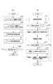
図2の(a)は、情報処理装置100が他の情報処理装置に画像データを送信する処理を示すフローチャートの一例である。本実施形態では、情報処理装置100において、モード選択やアプリケーションの起動により、記憶部113に記憶されたデータを送信する機能が起動されると、図2(a)のフローチャートが実行される。
FIG. 2A is an example of a flowchart illustrating processing in which the
ステップS201では、取得部110が、撮像部105が連続的に撮像している映像のうちの1フレームに相当する静止画像(リアルタイム画像)を取得する。そして、取得したリアルタイム画像を、検出部111、認識部112の処理対象として扱うため、RAM103に保持する。なお、ステップS201は、撮像部から1フレーム分の画像情報が入力される毎(つまり1フレーム毎)、あるいは数フレーム毎、あるいは所定時間毎に繰り返され、RAM103に記憶されるリアルタイム画像を更新する。
In step S <b> 201, the
ステップS202では、が、表示画面120に、ライブビュー画像と、記憶部113に記憶されている1以上の画像データのサムネイル画像とを表示させる表示画像を生成し、タッチパネルディスプレイ107に出力する。本実施形態では、表示画面120が、ライブビュー画像の表示領域と、1以上のサムネイル画像を一覧する表示領域とに分割され、両方の領域が同時に表示される(図5)。また、表示制御部115は、表示画像を構成する要素の位置情報をRAM103に保持する。
In step S <b> 202, a display image for displaying a live view image and a thumbnail image of one or more image data stored in the
ただし、表示画面の構成はこれに限られる例えばライブビュー画像が表示されている表示画面において、特定のアイコンに対するタップ操作が認識された時に、サムネイル画像が表示されるようにしてもよい。本実施形態では、記憶部113に記憶されている1以上の画像データのうち所定の数(例えば4)のデータのサムネイル画像を表示させ、当該領域内において左右方向のフリック操作が認識された場合には、順次表示させる4つのサムネイル画像を変更して表示する。なお、これにより、ある程度の視認性を保ったサイズでサムネイル画像を表示させることができ、ユーザはサムネイル画像を見ることで所望とする画像データを選択することができる。なお、本実施形態では、ライブビュー画像の表示領域では、撮像部105から入力され、表示用としてVRAM106に直接保持された画像情報を用いて、表示画面120に出力するライブビュー画像を生成した。しかし、取得部110が数フレーム毎に取得してRAM103に保持する静止画像(リアルタイム画像)を表示画面120に表示してもよい。
However, the configuration of the display screen is limited to this. For example, a thumbnail image may be displayed when a tap operation on a specific icon is recognized on a display screen on which a live view image is displayed. In the present embodiment, when a predetermined number (for example, 4) of thumbnail images of one or more pieces of image data stored in the
ステップS203では、RAM103に保持されたリアルタイム画像から、物体の検出と認識を行うことによって、送信先の候補の情報を取得する処理が実行される。この処理において、リアルタイム画像において、送信先の候補となる他の情報処理装置が写っている領域が検出され、各領域の位置情報と各情報処理装置の送信先を示す情報とが関連付けられて保持される。
In step S <b> 203, a process of acquiring information on a transmission destination candidate is performed by detecting and recognizing an object from the real-time image stored in the
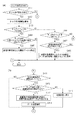
次に、図2の(b)は、本実施形態のステップS203において実行される、送信先の候補の情報を取得する処理を示すフローチャートの一例である。 Next, (b) of FIG. 2 is an example of a flowchart showing processing for acquiring candidate information of a transmission destination executed in step S203 of the present embodiment.
ステップS211では、検出部111が、取得部110によってRAM103に保持されたリアルタイム画像から物体を検出する処理を実行する。本実施形態では、リアルタイム画像中から検出する対象となる物体は、人の顔、および2次元バーコードである。
In step S <b> 211, the
本実施形態では、リアルタイム画像全体から検出対象となる物体が写っている領域を検出するために、リアルタイム画像の一部を部分領域として抜き出し、解析することで、その部分領域が、検出対象が写っている領域に該当するか否かを計算する。抽出する部分領域の位置と大きさを走査することで、最も適切な部分領域を求め、検出対象の物体が写っている領域(検出領域)として検出する。そして、その領域を示す情報をRAM103に保持する。
In this embodiment, in order to detect an area in which an object to be detected is captured from the entire real-time image, a part of the real-time image is extracted as a partial area and analyzed, so that the partial area includes the detection target. It is calculated whether it corresponds to the area. The most appropriate partial area is obtained by scanning the position and size of the partial area to be extracted, and is detected as an area (detection area) in which the object to be detected is shown. Information indicating the area is stored in the
図3は、本実施形態のステップS211において実行される、物体検出処理の詳細を示すフローチャートの一例である。 FIG. 3 is an example of a flowchart showing details of the object detection process executed in step S211 of the present embodiment.
ステップS301では、検出部111が、物体の検出で用いる検出枠の大きさの初期値を決定する。検出枠とは、リアルタイム画像から部分領域として抽出する部分を区分する枠であり、本実施形態では正方形である。検出枠の大きさの初期値は、検出枠の取り得る最小値か最大値であることが一般的である。
In step S301, the
ステップS302では、検出部111が、RAM103に保持されているリアルタイム画像全体のうち、物体を検出する処理を行う領域を決定する。通常はリアルタイム画像の全体の領域を検出の対象領域として決定する。ただし、リアルタイム画像を撮像している環境に制約がある場合などはこの限りではない。
In step S <b> 302, the
ステップS303では、検出部111が、ステップS302で決定した大きさの検出枠を、物体検出を行う領域内の初期位置に配置する。
In step S303, the
ステップS304では、検出部111が、リアルタイム画像の画像情報と、配置されている検出枠の情報に基づいて取得した検出枠内の画素情報を解析し、配置されている検出枠内が、検出対象の物体が写っている領域に相当するか否かを判定する。このとき、検出枠の大きさと検出物体の大きさの関係が適切であることも含めて判定する。本実施形態では、2次元バーコード、もしくは人の顔のいずれかが写っている領域に相当するか否かが判定される。この処理には、公知の画像判定技術を用いられ、本実施形態の特徴ではないため、説明を省略する。
In step S304, the
ステップS305では、検出部111が、リアルタイム画像から、検出対象の物体が写った領域が検出されたか否かを判定する。検出部111は、ステップS304において、配置されている検出枠内が、検出対象の物体が写っている領域に相当すると判定された場合に、検出対象の物体が写った領域が検出されたと判定する。検出対象の物体が写った領域が検出されたと判定された場合は(ステップS305でYES)、ステップS306に進む。検出対象の物体が写った領域が検出されていないと判定された場合は(ステップS305でNO)、ステップS307に進む。
In step S <b> 305, the
ステップS306では、検出部111が、ステップS304において、検出対象の物体が写っている領域に相当すると判定された領域を、検出対象の物体が写った領域としてその情報をRAM103に保持する。本実施形態では、検出枠の中心座標と大きさ(1辺の長さ)を示す情報が保持される。
In step S306, the
ステップS307では、検出部111が、この時点で設定されている大きさの検出枠を用いて、ステップS302で設定された領域全体に対する処理が実行されたか否かを判定する。この大きさの検出枠によって領域全体に対する処理が実行されたと判定された場合は(ステップS307でYES)、ステップS309に進む。この大きさの検出枠によって領域全体に対する処理が実行されていないと判定された場合は(ステップS307でNO)、ステップS308に進む。
In step S307, the
ステップS308では、検出部111が、検出枠をステップS302で設定された対象領域内で移動させて、ステップS304に戻る。検出枠を移動させる方法は、初期位置から横方向に所定の距離ずつ移動させる度に処理を行い、横方向の移動が終了したら、縦方向に所定の距離ずつ移動させて、横方向の移動を繰り返すことで領域全体を走査していく、という方法が一般的である。例えば、検出枠の大きさとして一辺が128ドット、対象領域が横800ドット縦480ドットである場合には、まず横方向に1ドットずつ移動する処理を行う度にステップS304〜ステップS308の処理を実行する。そして、672回横に移動させた後、1ドットずつ縦に移動させる度にステップS304〜ステップS308の処理を実行する。
In step S308, the
一方、ステップS309では、検出部111が、検出枠の大きさを、この時点までに設定された大きさからさらに変更できないかどうか判定する。つまり、設定可能な1以上の検出枠の大きさのパターン全てについて、検出枠を移動させながら検出対象の物体が写っている領域を探索する処理が行われたか否かを判定する。検出枠の大きさをさらに変更できると判定された場合は(ステップS309でNO)、ステップS310に進む。検出枠の大きさを変更できないと判定された場合は(ステップS309でYES)、取り得る大きさと位置の検出枠について、くまなく物体検出処理を行ったことになるため、処理を終了し、図2(b)のフローチャートにリターンする。
On the other hand, in step S309, the
ステップS310では、検出部111が、検出枠の大きさを変更して、ステップS303の処理に戻る。ステップS301で決定した検出枠の大きさの初期値が最小値であった場合は、検出枠の大きさを一段階ずつ大きく変更する。逆に、ステップS301で決定した検出枠の大きさの初期値が最大値であった場合は、検出枠の大きさを一段階ずつ小さくする。例えば、検出枠の大きさとして一辺が128ドット、256ドット、384ドット、及び512ドットの4種類が設定可能で、ステップS301で初期値が最小値(128ドット)と決定された場合、128ドットでの処理が終了したら、次は256ドットに変更する。そして各大きさでの処理が終了する度に、256ドット、384ドット、512ドットと段階的に大きく変更していく。
In step S310, the
なお、以上説明した物体検出処理は、予め設定された検出対象の種類別に実行してもよく、あるいはステップS304において、予め設定された検出枠内に、予め設定された検出対象のいずれかが写っているか否かを一度に判定するようにしてもよい。 The object detection process described above may be executed for each type of detection target set in advance, or in step S304, one of the detection targets set in advance is captured in the detection frame set in advance. It may be determined at once whether or not.
図2(b)の処理にリターンすると、ステップS212では、検出部111が、ステップS211で実行した物体検出処理によって、1以上の物体を検出したかを判定する。1以上の物体を検出していた場合は(ステップS212でYES)、ステップS213に進む。1以上の物体を検出していなかった場合は(ステップS212でNO)、処理を終了して図2(a)のメイン処理にリターンする。
Returning to the process of FIG. 2B, in step S212, the
ステップS213では、表示制御部115が、ライブビュー画像の表示領域に重畳して、ステップS211で検出した領域を明示する表示画像を生成し、タッチパネルディスプレイ107に出力する。例えば、破線によって領域を囲むようにして明示する。なお、取得部110が、撮像部105から連続的に入力されるフレーム毎の画像情報のうち、数フレーム毎に処理対象とするリアルタイム画像を取得している場合、検出処理が行われなかったフレームの画像がライブビュー画像として表示される状況が生じる。この場合、本実施形態では、前回検出処理を行ったフレームにおいて検出された領域を維持する。従って、ステップS213では、取得部110が新しくリアルタイム画像を取得するまで、前回明示された領域情報が維持される。ただし、別途検出された物体を追跡する画像処理を行うことで、検出領域を更新し、ステップS213にも、明示される領域を移動させることもできる。
In step S <b> 213, the
ステップS214では、認識部112が、ステップS211で検出された領域の画像情報を解析し、物体を特定する物体認識処理が実行される。例えば、人の顔が写った領域の画像の特徴と、予め保持されている顔情報との比較から、処理対象となっているリアルタイム画像に写った人が誰かを特定する。そして、その人の識別情報(例えば、情報処理装置100における登録名)、アドレス情報を取得し、それらを対応する領域の情報と関連付けてRAM103に保持する。あるいは、2次元バーコード情報を解析し、バーコード情報に含まれる、他の情報処理装置の識別情報とアドレス情報とを取得し、それらを対応する領域の情報と関連付けてRAM103に保持する。バーコード情報に、他の情報、例えば情報処理装置で実行される処理の制御に関する情報が含まれる場合には、それらもRAM103に保持される。 ステップS215では、認識部112が、ステップS214で実行した物体認識処理において、1以上の物体を認識したかを判定する。1以上の物体を認識していた場合は(ステップS215でYES)、ステップS216に進む。1以上の物体を認識していなかった場合は(ステップS215でNO)、処理を終了して図2(a)のメイン処理にリターンする。検出部111が1以上の物体を検出したにも関わらず、認識部112によって物体が認識されない場合は、例えば情報処理装置100に登録がない人の顔が検出された場合や、2次元バーコードが情報処理装置の識別情報やアドレス情報を含まなかった場合に当たる。従って、処理を終了する際に、その旨を示すエラーを表示するなどの処理を加えることによって、ユーザは状況を把握しやすくなる。
In step S214, the
ステップS216では、表示制御部115が、ライブビュー画像に重畳して、ステップS215で認識した物体の名称表示させる表示画像を生成し、出力する。本実施形態では、RAM103に保持された関連付け情報に基づいて、認識された物体の近傍に名称が表示されるように表示制御される。ただし、いずれの物体の名称であるかを識別可能であれば、物体上に重畳して表示させたり、名称表示専用の領域を設けたりしてもよい。また、ここで表示する名称は、ステップS214で取得された識別情報そのものでもよいし、より簡略化された情報であってもよい。例えば、物体が人であれば表示用のニックネームを表示したり、印刷装置であればどのような印刷形式のものであっても一律に「プリンタ」と表示したりすることもできる。ステップS216でも、ステップS213と同様に、認識処理の対象とされなかったフレームがライブビュー画像として表示されている場合には、前認識処理を行ったフレームでの認識結果を維持する。従って、ステップS216でも、取得部110が新しくリアルタイム画像を取得するまで、前回明示された名称とその表示位置が維持される。ただし、別途検出された物体を追跡する画像処理が行われる場合には、それに追従して表示位置を移動させることもできる。
In step S216, the
ステップS217では、認識した物体の名称を、ステップS306で保持された領域の情報に対応付けてRAM103に保持する完了したら、処理を終了し、図2(a)のメイン処理にリターンする。
In step S217, when the name of the recognized object is stored in the
上述したように、本実施形態の送信先候補取得処理では、表示画面においてライブビュー画像に重畳して、物体が検出されている領域を明示する(ステップS213)。領域が1箇所しか検出されない場合や、背景と物体との区別が容易な場合には、この処理は省略されることもできる。ただし、検出された領域を明示することによって、ユーザが、送信先の候補となる他の情報処理装置の位置を把握しやすくなるという効果がある。また、物体が検出されている領域が明示されない場合に、ユーザに、現在の撮影環境で得られるリアルタイム画像が適切でないことをフィードバックする効果もある。それによってユーザは、情報処理装置100の位置や角度を変えるなど、より良い環境でリアルタイム画像を取得するように調整することができる。同様に、本実施形態では、ライブビュー画像に重畳して、認識された物体の名称を重畳表示する(ステップS216)。この処理が省略されることで、ライブビュー画像全体の視認性を確保できる場合もある。ただし、認識された物体の名称を表示することによって、ユーザが、情報処理装置100が認識した物体を把握しやすくなるという効果がある。
As described above, in the transmission destination candidate acquisition process of the present embodiment, the region in which the object is detected is clearly indicated on the display screen so as to be superimposed on the live view image (step S213). If only one area is detected or if it is easy to distinguish the background from the object, this process can be omitted. However, by clearly indicating the detected area, there is an effect that it becomes easier for the user to grasp the position of another information processing apparatus that is a transmission destination candidate. Further, there is also an effect of feeding back to the user that the real-time image obtained in the current shooting environment is not appropriate when the area where the object is detected is not clearly shown. Thereby, the user can make adjustments such as changing the position and angle of the
図2(a)の処理にリターンすると、ステップS204では、タッチ操作に応答する処理が実行される。この処理において、送信対象の候補となる画像データのサムネイル画像に対して行われたタッチ操作を追跡し、当該画像データを送信する送信先の装置が指定されたことを認識する。本実施形態では、ユーザが、画像データに対応するサムネイル画像と、ライブビュー画像とを同時に表示画面に表示させた表示画面をタッチして、サムネイル画像をライブビュー画像中の他の情報処理装置の位置に移動させるドラッグ&ドロップ操作を認識する。このドラッグ&ドロップ操作を利用した画像の移動操作により、ドラッグされたサムネイル画像に対応する画像データが送信対象として特定され、ドロップ位置に関連付けられた情報処理装置が送信先として特定される。 Returning to the process of FIG. 2A, in step S204, a process of responding to the touch operation is executed. In this process, the touch operation performed on the thumbnail image of the image data that is a candidate for transmission is tracked, and it is recognized that the transmission destination apparatus for transmitting the image data is designated. In the present embodiment, the user touches the display screen on which the thumbnail image corresponding to the image data and the live view image are simultaneously displayed on the display screen, and the thumbnail image is displayed on another information processing apparatus in the live view image. Recognizes drag and drop operations that move to a position. By the image moving operation using this drag and drop operation, the image data corresponding to the dragged thumbnail image is specified as the transmission target, and the information processing apparatus associated with the drop position is specified as the transmission destination.
ここで、図4(a)及び(b)は、本実施形態のステップS204において実行される、ユーザによるタッチ操作の認識処理を表すフローチャートの一例である。なお、以下では、タッチパネルがユーザによって1箇所タッチされることによって行われるシングルタッチ操作を想定して説明する。 Here, FIGS. 4A and 4B are an example of a flowchart showing the recognition processing of the touch operation by the user, which is executed in step S204 of the present embodiment. In the following description, a single touch operation performed when the touch panel is touched at one place by the user will be described.
まず、図4(a)のフローチャートのステップS401では、受付部114が、タッチパネルディスプレイ107においてタッチ点が検出されたかを判定する。受付部114は、ステップS401の処理が実行されてから所定時間の間にタッチパネルディスプレイ107からタッチ点に関する情報が通知されたか否かに応じて判定を行う。タッチ点を検出した場合は(ステップS401でYES)、ステップS402に進む。タッチ点を検出していない場合は(ステップS401でNO)、処理を終了する。
First, in step S401 in the flowchart of FIG. 4A, the
ステップS402では、受付部114が、ステップS401で受け付けたタッチ点に関する情報をRAM103に保持する。本実施形態では、タッチイベントを示す情報、検出されたタッチ点の位置を示す座標情報(タッチ検出の対象領域を座標平面とする)、タッチ点が検出された時刻を示す情報を保持する。
In step S <b> 402, the
ステップS403では、受付部114が、ステップS401で受け付けたタッチイベントが「DOWN」であるか否か判定する。タッチイベントが「DOWN」である場合は(ステップS403でYES)、ステップS404に進む。タッチイベントが「DOWN」でない場合は(ステップS403でNO)、ステップS406に進む。
In step S403, the
ステップS404では、表示画面において、ステップS401で検出されたタッチ点の位置に、サムネイル画像が表示されているか否かを判定する。本実施形態では、検出されたタッチ点の位置にステップS202で表示したサムネイル画像の表示位置との関係に基づいて判定する。タッチ点の位置にサムネイル画像が表示されていると判定された場合(ステップS404でYES)、ステップS405に進む。タッチ点の位置にサムネイル画像が表示されていないと判定された場合は(ステップS404でNO)、処理を終了し図2(a)のメイン処理にリターンする。 In step S404, it is determined whether a thumbnail image is displayed at the position of the touch point detected in step S401 on the display screen. In the present embodiment, the determination is made based on the relationship between the position of the detected touch point and the display position of the thumbnail image displayed in step S202. If it is determined that a thumbnail image is displayed at the position of the touch point (YES in step S404), the process proceeds to step S405. If it is determined that the thumbnail image is not displayed at the position of the touch point (NO in step S404), the process ends and the process returns to the main process in FIG.
ステップS405では、送信制御部116が、送信対象候補となる画像データを特定する。そして、特定された送信対象候補を示す情報をRAM103に保持して、処理を終了し図2(a)のメイン処理にリターンする。
In step S405, the
一方、ステップS406では、受付部114が、ステップS401で受け付けたタッチイベントが「MOVE」であるか否か判定する。タッチイベントが「MOVE」である場合は(ステップS406でYES)、ステップS407に進む。タッチイベントが「MOVE」ではない場合は(ステップS406でNO)、ステップS411に進む。ステップS411に進むのは、タッチイベントが「DOWN」でも「MOVE」でもない場合、つまり「UP」の場合に相当する。
On the other hand, in step S406, the
ステップS407では、受付部114が、送信対象候補が特定されているか否かを判定する。具体的には、RAM103にステップS405で特定された送信対象候補の情報が保持されているか否かに基づいて判定する。送信対象候補が特定されている場合は(ステップS407でYES)、ステップS408に進む。送信対象候補が特定されていない場合は(ステップS407でNO)、処理を終了し図2(a)のメイン処理にリターンする。
In step S407, the
ステップS408では、表示制御部115が、ディスプレイ107に出力する表示画像を更新し、送信対象候補のサムネイル画像が、タッチ点の移動に追従して移動するように表示させる。このとき、保持されているタッチ点の情報のうち、1つ前に記録したタッチ点の位置を示す座標と、現在のタッチ点の位置を示す座標から、タッチ点が移動した方向と距離を算出し、送信対象候補のサムネイル画像を同様に移動させる。更新した表示画像が出力されたら、図2(a)のメイン処理にリターンする。このように、サムネイル画像がドラッグ操作によって移動される様子がユーザに明示される。
In step S408, the
次に、図4(b)を参照して、タッチイベント「UP」が検出された場合の処理を説明する。 Next, processing when the touch event “UP” is detected will be described with reference to FIG.
ステップS411では、受付部114が、送信対象候補が特定されているか否かを判定する。具体的には、RAM103にステップS405で特定された送信対象候補の情報が保持されているか否かに基づいて判定する。つまり、ステップS411では、ドラッグ操作されているサムネイル画像があるか否かを判定していることになる。送信対象候補が特定されている場合は(ステップS411でYES)、ステップS412に進む。送信対象候補が特定されていない場合は(ステップS411でNO)、処理を終了し図2(a)のメイン処理にリターンする。
In step S411, the
ステップS412では、表示画面において、ステップS401で検出されたタッチ点の位置(タッチイベント「UP」が通知されたタッチ点の位置)に、送信先候補の物体があるか否かを判定する。具体的には、ステップS306で保持された物体が写っている領域の情報に基づいて、検出された領域のいずれかに、タッチ点の位置が含まれるか否かを判定し、含まれる場合に、タッチ点の位置に送信先候補の物体があると判定する。タッチ点の位置に送信先候補の物体があると判定された場合(ステップS412でYES)、ステップS413に進む。タッチ点の位置に送信先候補の物体がないと判定された場合は(ステップS412でNO)、ステップS415に進む。 In step S412, it is determined whether or not there is a transmission destination candidate object at the position of the touch point detected in step S401 (the position of the touch point notified of the touch event “UP”) on the display screen. Specifically, it is determined whether or not the position of the touch point is included in any of the detected regions based on the information on the region in which the object held in step S306 is captured. , It is determined that there is a transmission destination candidate object at the position of the touch point. If it is determined that there is a transmission destination candidate object at the position of the touch point (YES in step S412), the process proceeds to step S413. If it is determined that there is no transmission destination candidate object at the position of the touch point (NO in step S412), the process proceeds to step S415.
ステップS413では、送信制御部116が、送信対象データと、送信先の情報処理装置を特定し、対応付ける。具体的には、ステップS405で送信対象候補として特定されていた画像データを確定した送信対象データとして特定し、ステップS412で、タッチ点の位置を含むと判定された領域に関連付けられたアドレス情報を送信先として特定する。そして、送信先のアドレス情報と、送信対象の画像データの情報を対応づける。ただし、クラウドサーバなど、外部記憶装置に記憶された画像データを送信する場合には、画像データ自体を直接送信するのではなく、クラウドサーバにおける画像データの識別情報(アドレス情報)を送信してもよい。この場合、ステップS413では、送信先のアドレス情報と、クラウドサーバにおける画像データの識別情報とが対応づけられる。これにより、送信先の識別情報を受信した他の情報処理装置では、その識別情報に基づいて、クラウドサーバ内の送信対象データを特定し、取得することができる。あるいは、クラウドサーバに対して、送信先として特定された情報処理装置の識別情報(アドレス情報)を含む情報を送信することによって、当該クラウドサーバに、送信先へ送信対象データを送信させることもできる。この場合、ステップS413では、送信先のアドレス情報、クラウドサーバのアドレス情報、送信対象の画像データを示す識別情報、クラウドサーバへの指示を示す情報が対応づけられる。
In step S413, the
さらに、ステップS413において、送信制御部116は、送信対象データの他に、送信先に送信されるべき情報を、送信先の情報処理装置のアドレス情報に対応づける。例えば、送信先の情報処理装置が印刷装置の場合には、送信対象データを印刷出力させる信号を、送信対象データの情報と共に送信することによって、ユーザは直感的な一流れの操作によって、送信先における出力処理もコントロールすることが可能になる。このような直感的な操作の実現のため、認識部112が認識した情報の中に、送信先の情報処理装置で実行される処理の制御に関わる情報が含まれている場合、送信制御部116は、それを送信先のアドレス情報に対応付ける。
Further, in step S413, the
ステップS414では、送信部117が、送信制御部116によって、特定された送信先の情報処理装置に対応付けられた情報に基づいて、送信対象データを、送信先の情報処理装置に送信させる処理を行う。この際、公知の技術によって適宜送信対象データを圧縮するなどの処理が加えられる。また、上述したように、送信部117は、メールアドレスやIPアドレスなど、認識されたアドレス情報の種類に応じた送信方法が選択される。クラウドサーバを介して送信先の情報処理装置に送信対象データを送信する形式の場合には、クラウドサーバに対して、送信先のアドレス情報に対応付けられた情報が送られる。
In step S414, the
ステップS415では、受付部114からドラッグ&ドロップ操作が入力されなかったことが各機能部に通知され、RAM103の情報が初期化されることによって情報処理装置100は初期状態に戻る。すなわち、送信制御部116によって送信対象と特定されていたオブジェクトの特定状態は、ドラッグ&ドロップ操作の終了時点で、送信先候補の物体が特定されない場合は解除される。そして処理を終了する。
In step S415, each function unit is notified that the drag and drop operation has not been input from the
図2(a)のメイン処理にリターンすると、ステップS205では、受付部114が他の情報処理装置にデータを送信する機能の終了が指示されたか否かを判定する。本実施形態では、受付部114が、表示画面において特定のアイコンの表示位置におけるタップ操作を受け付けた場合に、他の情報処理装置にデータを送信する機能の終了が指示されたと認識する。ただしこれに限らず、例えば物理ボタンによって、画像の再生モードなどが指定されたり、他のアプリケーションが起動されたりすることを、終了指示と判断してもよい。
When the process returns to the main process of FIG. 2A, in step S205, the
なお、図4(a)及び(b)を参照して説明した処理では、シングルタッチ操作を想定したが、複数箇所が同時にタッチされることによって行われるマルチタッチ操作によって、複数のサムネイル画像を同時にドラッグ&ドロップする操作を受け付けても構わない。その場合には、タッチ点を識別した上で、各タッチ点について上述した処理を実行する。 In the process described with reference to FIGS. 4A and 4B, a single touch operation is assumed. However, a plurality of thumbnail images are simultaneously displayed by a multi-touch operation performed by simultaneously touching a plurality of locations. You may accept drag and drop operations. In that case, after identifying the touch points, the above-described processing is executed for each touch point.
図5は、情報処理装置100を持つユーザの前に存在する被写体の状況と、それを撮像する情報処理装置100の関係を模式的に表す図である。被写体は、人物501、プリンタ503、及びテーブル505である。一方、情報処理装置100は撮像部105から被写体のリアルタイム画像を取得する(ステップS201)。そして、表示画面120には、ライブビュー画像と、それに重畳するように、サムネイル画像の一覧を提示する領域であるデータトレイ506とが表示される(ステップS202)。図5のデータとトレイ506には、サムネイル画像507〜510が表示されている。これらはそれぞれ、記憶部113に記憶された写真データに対応する。
FIG. 5 is a diagram schematically illustrating the relationship between the state of the subject existing in front of the user who has the
次に図5の情報処理装置100が行う物体の具体的な検出処理の様子を、図6を用いて説明する。なお、図3のフローチャートに示した、検出枠の大きさおよび位置の走査する処理は、本来表示画面には表示させずに行われるが、ここでは説明のため表示画面120中に明示して説明する。
Next, a specific object detection process performed by the
情報処理装置100は、二次元バーコードの検出で用いる検出枠602の大きさの初期値を決定する(ステップS301)。本実施形態では検出枠の大きさとして取り得る最小値を初期値として設定している。そして、物体検出の対象とする領域601を決定する(ステップS302)。本実施形態では、リアルタイム画像のうち、表示画面120において太線で表現された領域(データトレイ506に隠されずにライブビュー画像が表示される領域に相当する)が、対象領域601とされている。図6(a)は、初期値の大きさに設定された検出枠が、初期位置に配置された状態を示す(ステップS303)。そして、検出枠602内に検出対象となる物体が撮像されているか否かが判定される(ステップS304)。図6(a)の状態では、検出枠602の領域には二次元バーコードも人の顔も存在しないので、物体写っている領域に相当しないと判定される(ステップS305でNO)。
The
図6の(a)では、検出枠602が対象領域601の全てをまだ移動していないので(ステップS307でNO)、検出枠602が移動される(ステップS308)。図6(b)では、検出枠602を初期位置から向かって右に移動させている。
In FIG. 6A, since the
初期値のサイズの検出枠602で、検出領域全体の検出処理を終えた場合、検出枠602の大きさがまだ変更可能か否かが判定され(ステップS309)、可能な場合には検出枠の大きさを変更する処理が実行される(ステップ310)。図6の(c)は、検出枠602の大きさを一段階大きくなるように変更した様子を示す(ステップS310)。
When the detection process for the entire detection area is completed with the
図6の(d)は、大きさが変更された検出枠602における物体検出と移動を繰り返した後、検出枠602の領域が、検出対象の物体(二次元バーコード)が写っている領域に相当する様子を示す。検出枠602内に二次元バーコードが検出されるため(ステップS305でYES)、二次元バーコード504だと判定した検出枠602の領域を示す情報が保持される(ステップS306)。引き続き、検出枠602の位置と大きさを走査して検出処理を繰り返すことによって、人物501の顔502も検出することができる。
In FIG. 6D, after the object detection and the movement in the
図7の(a)は、上述したようにして検出された、二次元バーコード504の検出領域と、人の顔502の検出領域を、情報処理装置100が明示した様子を示す(ステップS213)。本実施形態では、検出した顔502の領域に破線で枠線701と、検出した二次元バーコード504の領域を破線で囲んだ枠線702が描画される。
FIG. 7A shows a state in which the
次に、検出された領域に対して認識処理を実行することにより、各物体が識別される(ステップS214)。図7(b)は、検出された領域のそれぞれに対して、認識した物体の名称が表示された様子を示す(ステップS216)。物体認識処理の結果、顔502は、情報処理装置100に予め記憶された人物501の顔である、と認識され、登録名である「A−san」という名称703が顔502の領域の上部に描画される。同様に、二次元バーコード504はプリンタ503だと認識され、二次元バーコードに含まれていた情報に基づき、「Printer X」という名称704が二次元バーコード504の領域の上部に描画される。
Next, each object is identified by performing recognition processing on the detected area (step S214). FIG. 7B shows a state in which the name of the recognized object is displayed for each detected area (step S216). As a result of the object recognition processing, the
図7(c)は、表示画面120に表示されている写真データ509をユーザが指705でタッチした状態を示す。表示画面120を指705がタッチされたことにより「DOWN」イベントが検出されるため(ステップS403でYES)、タッチされた位置に、サムネイル画像が表示されているかが判定される(ステップS404)。図7(c)では、指705がタッチしている位置にサムネイル509が表示されているため(ステップS404でYES)、サムネイル509に対応する写真データが送信対象候補として特定される(ステップS405)。
FIG. 7C shows a state in which the user touches the
次に、図7(d)は、指705が表示画面120をタッチした状態を維持したまま、移動している様子を示す。図4のフローチャートのステップS408まで処理した状態を表している。ここでは、指705が図7(c)のタッチ開始位置と異なる位置で検出されたことにより「MOVE」イベントが検出される(ステップS406でYES)。既に送信対象候補が特定されているので(ステップS407でYES)、写真データのサムネイル509を指705の移動に追従するように表示させる(ステップS408)。
Next, FIG. 7D shows a state in which the
図7(e)は、さらに指705が移動され、顔502の検出領域701内まで移動してから表示画面120からリリースされた状態を示す。ここで透過された指705は、表示画面120の表面から離れていることを表現している。「UP」イベントが検出され(ステップS406でNO)、既に送信対象候補が特定されているので(ステップS411でYES)、指705がリリースされた位置に、送信先候補となる物体があるか否かが判定される(ステップS412)。図7(d)では、タッチ「UP」が検出されたタッチ位置、すなわち指705がリリースされた位置は、顔502の検出領域701内である(ステップS412でYES)。従って、送信先の情報処理装置は、情報処理装置100に予め登録された人物501のアドレス情報が示す先であると特定される。そして、そのアドレス情報と送信対象データであるサムネイル509の写真データが対応づけられる(ステップS413)。そして、写真データが送信される(ステップS414)。例えば、人物501のアドレス情報としてメールアドレスが登録されている場合、送信先の情報処理装置はメールサーバに相当する。情報処理装置100は、サムネイル509に対応する写真データを添付したメールを、当該メールアドレス宛に送信する。勿論、メールアドレス欄に人物501のメールアドレスが選択された状態でメールアプリが起動し、メール本文を入力可能な状態を用意しても構わない。また例えば、人物501のアドレス情報として、人物501が所有する特定の情報処理装置のIPアドレスが登録されている場合には、LAN環境を利用して当該情報処理装置に直接写真データを送信することができる。
FIG. 7E shows a state in which the
以上説明したように、本実施形態では、表示画面に表示されたライブビュー画像に写っている検出対象を送信先の候補とする。これにより、ユーザは表示画面120をタッチすることなく、被写体に撮像部105を向けるだけで、送信先候補である物体を知ることができる。そして、本実施形態の情報処理装置100は、同じ表示画面に表示された送信対象の候補と関連付けられたオブジェクトを、移動させる操作を受け付ける。そして、移動されたオブジェクトに対応するデータが送信対象として、オブジェクトが移動された位置に被写体として写っている検出対象の物体を送信先として対応付ける。これにより、情報処理装置100の撮像部105で捕えられる範囲内の物体に対して、直感的な操作で情報を送信対象と送信先を設定することが可能となる。
As described above, in the present embodiment, a detection target in the live view image displayed on the display screen is set as a transmission destination candidate. Accordingly, the user can know the object that is the transmission destination candidate by simply pointing the
なお、本実施形態では随時更新されるライブビュー映像に対してドロップ操作を行うようにしたが、更新を行わず、リアルタイムで撮像された画像を一時的保持し表示している一時停止画面ドロップ操作の対象としても構わない。また、ポインティングデバイスを用いた操作としてタッチパネルを用いた物体接触による操作例を説明したが、これに限らない。例えば、マウスなど他のポインティングデバイスによる操作でも良い。 In this embodiment, the drop operation is performed on the live view video that is updated as needed. However, the update is not performed, and the pause screen drop operation that temporarily holds and displays an image captured in real time. It does not matter as the target. Moreover, although the operation example by the object contact using a touch panel was demonstrated as operation using a pointing device, it is not restricted to this. For example, an operation with another pointing device such as a mouse may be used.
<変形例1>
実施形態1の変形例1では、ユーザがオブジェクトのドラッグ&ドロップ操作を開始してから物体検出処理と物体認識処理を行うことにより、情報処理装置100の処理負荷を軽減する例を説明する。なお、これ以降の変形例で実行される処理を説明する各フローチャートにおいて、実施形態1のフローチャートと同じ番号を付した処理ステップでは、実施形態1の当該処理ステップと同じ処理が行われるため、適宜説明を省略する。
<Modification 1>
In the first modification of the first embodiment, an example will be described in which the processing load of the
変形例1に係る情報処理装置100のハードウェア構成、及び機能構成は、実施形態1の図1(a)、(b)と同様であるため、説明を省略する。
Since the hardware configuration and the functional configuration of the
図8は、変形例1において、情報処理装置100が他の情報処理装置に画像データを送信する処理を示すフローチャートの一例である。変形例1においても、情報処理装置100において、モード選択やアプリケーションの起動により、記憶部113に記憶されたデータを送信する機能が起動されると、図8のフローチャートが実行される。実施形態1における図2のフローチャートとは、ステップS203の送信先候補取得処理が無く、ステップS202においてライブビュー画像とサムネイル画像一覧が表示された後に、ステップS204Aでタッチ操作認識処理が実行される点が異なる。それ以外の処理は実施形態1と同じため、詳細な説明は省略する。
FIG. 8 is an example of a flowchart illustrating processing in which the
図9は変形例1のステップS204Aにおいて実行される、タッチ操作認識処理を示すフローチャートの一例であり、実施形態1の図4のフローチャートに対応する。 FIG. 9 is an example of a flowchart illustrating the touch operation recognition process executed in step S204A of the first modification, and corresponds to the flowchart of FIG. 4 of the first embodiment.
ステップS411までの処理は、実施形態1と同じであるため、説明を省略する。実施形態2では、ステップS411において、受付部114が、送信対象候補が特定されていると判定した場合(ステップS411でYES)、ステップS203Aの送信先候補取得処理に進む。ステップS203Aでは、実施形態1と同様に、図3のフローチャートに従って、リアルタイム画像から送信先候補を取得する処理が実行される。そして、ステップS309において、検出部111が、検出枠の大きさを、この時点までに設定された大きさからさらに変更できないと判定した場合(ステップS309でYES)、図9のフローチャートにリターンしてステップS412に進む。ステップS412以降の処理は、実施形態1と同様に実行される。
Since the processing up to step S411 is the same as that of the first embodiment, the description thereof is omitted. In the second embodiment, when the
ここで図10は、変形例1に係る情報処理装置100を、図5と同じ環境で使用する様子を表す。表示画面120に表示された内容は、実施形態1の図5と同一であるものとする。以下、変形例1に係る情報処理装置100の具体的な操作例を、図10を用いて説明する。
Here, FIG. 10 illustrates a state in which the
図10(a)は、ユーザが指705でサムネイル画像509を人物501の顔502の上までドラッグ&ドロップして指を離した様子を表している。図10においても、透過された指705は、表示画面120の表面から離れていることを表現している。ただし、変形例1では、図7の(c)とは異なり、この時点で顔502、及び二次元バーコード504は検出も認識もされていないため、枠線は表示されていない。図10(a)の操作例では、「UP」イベントが検出され(ステップS406でNO)、既に送信対象候補がサムネイル509に対応する写真データと特定されている(ステップS411でYES)ことから、ステップS203Aの送信先候補取得処理に進む。
FIG. 10A shows a state in which the user drags and drops the
図10(b)は、ステップS203Aの送信先候補取得処理によって、人物501の顔502とプリンタ503の二次元バーコード504が検出され、各領域が明示された様子を示す(ステップS213)。変形例1においても、検出された領域は破線で囲われることによって明示される。また、図10の(c)では、顔502が人物501、二次元バーコード504はプリンタ503だと認識され、名称が表示された様子を示す(ステップS216)。ステップS211で物体を認識したと判定され、ステップS212で、認識した人物501の「A−san」という名称703が顔502の上部に描画される。同様に、認識したプリンタ503の「Printer X」という名称704が二次元バーコード504の上部に描画される。
FIG. 10B shows how the
そして、「UP」イベントが検出されたタッチ点の位置に、送信先候補の顔502がある(ステップS412でYES)ため、送信先の情報処理装置は、情報処理装置100に予め登録された人物501のアドレス情報が示す先であると特定される。そして、そのアドレス情報と送信対象データであるサムネイル509の写真データが対応づけられる(ステップS413)。そして、写真データが送信される(ステップS414)。
Since there is a transmission
以上説明したように、変形例1では、ユーザがオブジェクトをドロップするまで物体の検出処理と認識処理を行わない。これにより、随時取得されるリアルタイム画像に対して常に物体検出処理と物体認識処理を実行することによって情報処理装置100にかかる処理負荷を低減することができる。また、変形例1では、オブジェクトをドロップしたことに応じて、物体検出処理が開始されることとしたが、ユーザがオブジェクト上をタッチした事に応じて物体検出処理が開始されるようにしてもよい。その場合には、ステップS203Aの処理は、ステップS405の後に実行され、タッチ操作を追跡するのと並行して物体検出処理と物体認識処理を行う。このようにすることで、ユーザの操作中に処理を開始できるので、ドロップ操作の後にユーザが送信先候補の取得処理の終了を待機する時間が削減できる。
As described above, in Modification 1, the object detection process and the recognition process are not performed until the user drops the object. Thereby, the processing load applied to the
<変形例2>
次に、変形例2として、変形例1における物体の検出処理で用いる検出対象領域を、データがドロップされた座標の周辺に絞ることで必要な画像処理量を削減し、さらに処理負荷を低減する例を説明する。
<Modification 2>
Next, as a second modification, the detection target area used in the object detection process in the first modification is reduced to the periphery of the coordinates where the data is dropped, thereby reducing the necessary image processing amount and further reducing the processing load. An example will be described.
変形例2のステップS203Aでは、図8(b)のフローチャートに従って送信先候補取得処理が実行される。図2(b)と異なる点は、ステップS211Aにおいて、図11のフローチャートに従って、物体検出処理が実行される点である。 In Step S203A of Modification 2, a transmission destination candidate acquisition process is executed according to the flowchart of FIG. 8B. The difference from FIG. 2B is that the object detection process is executed in step S211A according to the flowchart of FIG.
図11は変形例2のステップS211Aにおいて実行される物体検出処理のフローチャートの一例である。図3のフローチャートと異なる点は、ステップS301において検出枠の大きさの初期値が設定された後、物体検出を行う領域を決定する処理である。変形例2では、ステップ1102において、タッチ点がリリースされた座標と、検出枠の大きさに基づいて物体検出を行う領域を決定する。変形例1では、物体検出の対象領域を、ユーザがデータをドロップした座標(タッチをリリースした座標)中心とし、この時点で設定されている検出枠の大きさの4倍面積の正方形領域を検出の対象領域の基準としている。決定された検出対象領域に対して実行されるステップS303〜ステップS309の処理は、変形例1と同様である。ただし、変形例2では、ステップS309において、検出枠の更に変更できると判定された場合(ステップS309でYES)、ステップS310で検出枠の大きさを変更した後、ステップS302Bに戻り、検出対象領域を再度決定する。この他の処理は、変形例1と同様であるため説明を省略する。 FIG. 11 is an example of a flowchart of the object detection process executed in step S211A of the second modification. The difference from the flowchart of FIG. 3 is processing for determining an area in which object detection is performed after the initial value of the size of the detection frame is set in step S301. In the second modification, in step 1102, an area where object detection is performed is determined based on the coordinates at which the touch point is released and the size of the detection frame. In the first modification, the object detection target area is set to the center where the user dropped the data (coordinate where the touch was released), and a square area having an area four times the size of the detection frame set at this time is detected. This is the standard for the target area. The processing of Step S303 to Step S309 executed for the determined detection target region is the same as that of Modification 1. However, in Modification 2, if it is determined in step S309 that the detection frame can be further changed (YES in step S309), the size of the detection frame is changed in step S310, and then the process returns to step S302B to detect the detection target region. Determine again. Since other processes are the same as those of the first modification, the description thereof is omitted.
ここで変形例2に係る情報処理装置100を、図5と同じ環境で使用する様子を表す。表示画面120に表示された内容は、実施形態1の図5と同一であるものとする。以下、変形例1に係る情報処理装置100の具体的な操作例を、図10を用いて説明する。
Here, a state in which the
図10(a)は、ユーザが指705でサムネイル画像509を人物501の顔502の上までドラッグ&ドロップして指を離した様子を表している。図10においても、透過された指705は、表示画面120の表面から離れていることを表現している。ただし、変形例1では、図7の(c)とは異なり、この時点で顔502、及び二次元バーコード504は検出も認識もされていないため、枠線は表示されていない。図10(a)の操作例では、「UP」イベントが検出され(ステップS406でNO)、既に送信対象候補がサムネイル509に対応する写真データと特定されている(ステップS411でYES)ことから、ステップS203Aの送信先候補取得処理に進む。
FIG. 10A shows a state in which the user drags and drops the
次に図11のフローチャートの物体検出処理の具体的な検出処理の様子を、10(d)〜(f)を用いて説明する。なお、図11のフローチャートに示した、検出対象領域を決定し、検出枠の大きさおよび位置の走査する処理は、本来表示画面には表示させずに行われるが、ここでは説明のため表示画面120中に明示して説明する。 Next, a specific detection process of the object detection process in the flowchart of FIG. 11 will be described using 10 (d) to 10 (f). The process of determining the detection target region and scanning the size and position of the detection frame shown in the flowchart of FIG. 11 is originally performed without being displayed on the display screen. This will be described in detail in 120.
図10(d)は、ユーザがタッチをリリースした位置1001の座標を中心に、初期値の大きさに設定された検出枠602の4倍の面積の正方形が、検出処理の対象領域に設定された状態を示す(ステップS302B)。変形例2においても、検出枠の大きさの初期値としては、取り得る最小値(検出枠内の検出対象の有無を画像処理により判別できる最小のサイズ)を設定している。タッチ点1001の座標を中心とした、縦横それぞれが検出枠602の2倍の領域を対象領域1002として決定している。ユーザがサムネイル画像509をドロップした位置に、ユーザが送信先として設定したい物体が存在する可能性が高いことから、対象領域をドロップ位置の周辺に絞ることで、送信先の候補を絞ることができる。なお、ここで説明した「2倍」は一例であり、別の倍率の領域を対象とすることも可能である。
In FIG. 10D, a square having a quadruple area of the
図10(e)は、初期値で設定された大きさの検出枠によって対象領域全体を走査し終えたことに応じて、検出枠602の大きさを変更し(ステップS310)、検出対象領域が新たに決定された状態を示す(ステップS302B)。図10(f)は、新たに決定された対象領域全体を走査し終えたことに応じて、検出枠の大きさの変更が繰り返され(ステップS310)、対象領域がさらに更新された様子を表している。
FIG. 10 (e) changes the size of the
そして、図10の(f)は、さらに検出枠の大きさが変更されたあと(ステップS310)、人物501の顔領域602が検出された様子を表す(ステップS305でYES)。図10(f)では、設定された検出枠の縦「2倍」に当たる対象領域の縦サイズは、リアルタイム画像の縦サイズが上限に当たる。さらに、ドロップ位置を中心したことにより、向かって右側もリアルタイム画像の右端に達しているため、対象領域は正方形とならない。このように、対象領域は、検出枠の4倍の面積の正方形を基準として、リアルタイム画像の大きさと、ドロップ位置とに応じて適宜調整される。
FIG. 10F shows how the
以上説明したように、変形例2では、ユーザがオブジェクトをドロップしたことに応じて物体検出処理と物体認識処理を行い、その際、リアルタイム画像中で検出物体処理の対象とする対象領域を、ドロップ位置の座標の周辺に絞る。絞られた対象領域で、送信先候補となる物体が検出されなかった場合には、徐々に対象領域を拡大していく。ユーザがオブジェクトをドロップした位置には、ユーザが送信先として設定したい情報処理装置が写っている可能性が高い。従って、変形例2のように、ドロップ位置の周辺から優先的に物体検出を行うことで、早期にユーザが所望とする送信先の候補を提示できる。これにより、検出処理に係る負荷と低減し、効率的に妥当な送信先の候補を提示することができる。 As described above, in the second modification, the object detection process and the object recognition process are performed in response to the user dropping the object, and at that time, the target area to be detected in the real-time image is dropped. Narrow down around the coordinates of the position. When an object that is a transmission destination candidate is not detected in the narrowed target area, the target area is gradually enlarged. There is a high possibility that the information processing apparatus that the user wants to set as the transmission destination is shown at the position where the user dropped the object. Therefore, by performing object detection preferentially from the periphery of the drop position as in Modification 2, it is possible to present a transmission destination candidate desired by the user at an early stage. As a result, it is possible to reduce the load related to the detection process and efficiently present a suitable transmission destination candidate.
<変形例3>
次に、変形例3として、リアルタイム画像が取得される度に物体検出処理を行い、ユーザがオブジェクトのドラッグ操作を開始したことに応じて物体認識処理を行う例を説明する。
<Modification 3>
Next, as a third modification example, an example will be described in which an object detection process is performed every time a real-time image is acquired, and an object recognition process is performed in response to the user starting an object drag operation.
これにより、ユーザは、物体を送信先として指定し得るか否かを、当該物体にカメラを向けるだけで容易に把握することができるとともに、情報処理装置は物体認識処理に係る処理負荷を低減することができる。 Thereby, the user can easily grasp whether or not the object can be designated as the transmission destination simply by pointing the camera at the object, and the information processing apparatus reduces the processing load related to the object recognition process. be able to.
変形例3に係る情報処理装置100のハードウェア構成、及び機能構成は、実施形態1の図1(a)、(b)と同様であるため、説明を省略する。
Since the hardware configuration and the functional configuration of the
変形例3の場合、図12(a)のフローチャートに従った処理により、ステップS203Cの送信先候補取得処理が呼び出され、ステップS213で検出した物体を表す領域を明示するまでは実施形態1と同様に行われる。変形例3では、ステップS213において検出した物体を表す領域を明示したら、ステップS204Cのタッチ操作認識処理が開始される。図13は、変形例3のステップS204Cにおいて実行されるタッチ操作認識処理を示すフローチャートの一例である。ステップS408までは、実施形態1の図4のフローチャートと同様の処理が実行される。 In the case of the third modification, the transmission destination candidate acquisition process in step S203C is called by the process according to the flowchart in FIG. 12A, and the same as in the first embodiment until the region representing the object detected in step S213 is clearly indicated. To be done. In the third modification, when the region representing the object detected in step S213 is clearly indicated, the touch operation recognition process in step S204C is started. FIG. 13 is an example of a flowchart illustrating the touch operation recognition process executed in step S204C of the third modification. Up to step S408, processing similar to the flowchart of FIG. 4 of the first embodiment is executed.
変形例3では、ステップS408において、タッチ点にサムネイル画像を追従させる表示を開始すると同時に、ステップS1301の物体認識処理に進む。ここで、図14(a)は、ステップS1301において実行される物体認識処理の一例を示すフローチャートである。ステップS214〜ステップS217の各ステップで実行される処理は、実施形態1の図2(b)のフローチャートと同じであるため、説明を省略する。ステップS217において、認識した物体の名称を、ステップS306で保持された領域の情報に対応付けてRAM103に保持する完了したら、処理を終了し、図13のタッチ操作認識処理にリターンする。以降の処理は実施形態1の図4のフローチャートと同じであるため、説明を省略する。
In the third modification, in step S408, display for causing the thumbnail image to follow the touch point is started, and at the same time, the process proceeds to object recognition processing in step S1301. Here, FIG. 14A is a flowchart illustrating an example of the object recognition process executed in step S1301. The processing executed in each step from step S214 to step S217 is the same as that in the flowchart of FIG. In step S217, when the name of the recognized object is stored in the
ここで、図15は、変形例3に係る情報処理装置100を、図5と同じ環境で使用する様子を表す。表示画面120に表示された内容は、実施形態1の図5と同一であるものとする。以下、変形例3に係る情報処理装置100の具体的な操作例を、図15を用いて説明する。
Here, FIG. 15 illustrates a state in which the
図15(a)は、二次元バーコード504の検出領域と、人の顔502の検出領域を、情報処理装置100が明示した様子を示す(ステップS213)。変形例3においても、検出された領域は破線で囲われることによって明示される。ここまでは実施形態1の図7の(a)と同様であるが、変形例3の場合、この段階では物体認識処理は開始されない。従って、図7(b)のように、顔502の人物501の名称「A−san」と、及び二次元バーコード504のプリンタ503の名称「Printer X」は描画されはしない。
FIG. 15A shows a state where the
図15(b)は、ユーザが指705でサムネイル画像509のドラッグ操作が開始されたのに応じて、物体認識処理(ステップS1301)が行われ、その結果が表示された様子を示す。変形例3では、図15(a)の状態から、ユーザが写真データ509を顔502の方向にドラッグしたので、人物501とプリンタ503が認識され(ステップS214)、「A−san」と「Printer X」という名称が描画される(ステップS217)。
FIG. 15B shows a state in which the object recognition process (step S1301) is performed and the result is displayed in response to the user starting the drag operation of the
以上説明したように、変形例3では、ユーザがオブジェクトのドラッグ操作を開始するまで物体の認識処理を行わない。これにより、リアルタイムの映像に対して常に物体の認識処理を実行する場合に比べて情報処理装置100の処理負荷を軽減しつつも、情報処理装置100にどんな物体が検出されているかをユーザが把握しやすくなる。また、さらにオブジェクトの表示位置で「DOWN」イベントが検出された段階で物体検出処理を行い、検出された領域において「UP」イベントが検出されたことに応じて物体認識処理を行うようにすることもできる。
As described above, in the third modification, the object recognition process is not performed until the user starts the drag operation of the object. As a result, the user can grasp what object is detected in the
<変形例4>
変形例4では、変形例3のようにユーザがドラッグ操作を開始したことに応じて物体認識処理を行う場合に、送信先候補を示す複数の領域に対して認識処理を行う順番を、ユーザのドラッグ操作方向に基づいて制御する例を説明する。
<Modification 4>
In the fourth modification, when the object recognition process is performed in response to the user starting the drag operation as in the third modification, the order in which the recognition process is performed on the plurality of regions indicating the transmission destination candidates is changed. An example of control based on the drag operation direction will be described.
図16の(a)は、変形例4における情報処理装置100の機能構成を表すブロック図である。図1の(b)のブロック図と異なる点は、距離取得部1601が追加された点である。距離取得部1601は、CPU101、ROM102、RAM103等で構成され、受付部114により受け付けられるドラッグ操作が開始された位置と、検出部111に検出された領域との、表示画面120上での距離を取得する。そして、取得した距離が小さい順に、検出部111により検出された領域に、物体認識処理を行う順番を設定する。変形例4の認識部112は、距離取得部1601によって設定された順番に従って、各領域における物体認識処理を実行する。
FIG. 16A is a block diagram illustrating a functional configuration of the
変形例4の場合も、変形例3と同様、図12(a)フローチャートに従った処理により、ステップS203Cの送信先候補取得処理が呼び出される。ステップS213において検出した物体を表す領域を明示したら、ステップS204Cのタッチ操作認識処理が開始される。そして、ステップS408において、タッチ点にサムネイル画像を追従させる表示を開始すると同時に、ステップS1301の物体認識処理に進む。 In the case of the modified example 4, as in the modified example 3, the transmission destination candidate acquisition process in step S203C is called by the process according to the flowchart of FIG. If the area | region showing the object detected in step S213 is specified, the touch operation recognition process of step S204C will be started. In step S408, display for causing the thumbnail image to follow the touch point is started, and at the same time, the process proceeds to object recognition processing in step S1301.
ただし、変形例4では、ステップS1301において実行される物体認識処理は、図14(b)のフローチャートに従って実行される。まず、ステップS1401において、距離取得部1601が、「MOVE」イベントが検出されたタッチ点が移動した方向を取得する。変形例4では、表示画面120上に定義された座標平面において、「DOWN」イベントが検出された時のタッチ点の位置と、直前に「MOVE」イベントが検出されたタッチ点の位置を通る直線を示す式を算出することによって取得される。ただし、連続して「MOVE」イベントが検出されたタッチ点を通る直線を算出してもよい。そして距離取得部1601は、ステップS306でRAM103に保持された領域の情報から、各領域の中心点の座標を得る。そして、各領域の中心点から、算出した直線に下ろした垂線の長さを算出することで、ドラッグ操作が開始された位置と、検出部111の検出される物体との、表示画面120上での距離を取得する。ただし、変形例4では、このような算出方法により距離を取得する方法に限らない。例えば、表示画面120上を複数の部分領域に分割し、ドラッグ操作が開始された位置と、検出領域の中心点が含まれる部分領域の位置関係に応じた所定の距離を取得するなど、様々な方法を用いることができる。
However, in the modified example 4, the object recognition process executed in step S1301 is executed according to the flowchart of FIG. First, in step S1401, the
次に、ステップS1402では、距離取得部1601が、取得された距離が短い領域から順に、物体認識処理が行われるように、RAM103に保持されている各領域に順番を設定する。RAM103では、各領域の情報に順番を示す情報が付加され、認識部112に通知される。次に、ステップS1403では、認識部112が、ステップS1402で設定された順番に沿って、検出部111が検出した領域を1つ選択する。ステップS214〜ステップS217の各ステップで実行される処理は、実施形態1の図2(b)のフローチャートと同じであるため、説明を省略する。変形例4では、ステップS217において、認識結果の情報と、領域の情報を対応付けて保持した後、ステップS1404において、認識部112が、RAM103に情報が保持されている全ての領域に対する物体認識処理が処理済みか否かを判定する。全ての領域に対する物体認識処理が処理済みではない、すなわち処理していない領域が残っていると判定された場合(ステップS1404でNO)には、ステップS1403に戻り、設定された順番が次の領域が選択される。全ての領域に対する物体認識処理が処理済みであると判定された場合(ステップS1404でYES)には、処理を終了し、図13のタッチ操作認識処理のフローにリターンする。以降の処理は実施形態1の図4のフローチャートと同じであるため、説明を省略する。
Next, in step S1402, the
図15(c)は、変形例4において、ドラッグ操作が開始された位置と、検出されている領域との距離に基づいて物体認識処理が開始される様子を示す。図15の(c)では、ユーザが図15(a)の状態から、サムネイル画像509に対するドラッグ操作のため、タッチ点を位置1501から位置1502へと移動させている。
FIG. 15C shows a state in which the object recognition process is started based on the distance between the position where the drag operation is started and the detected area in the fourth modification. In FIG. 15C, the user moves the touch point from the
ここで、ステップS1401において破線1505は、距離取得部1601によって算出される、位置1501と位置1502を通る直線を示す。また、点1503は、顔502が検出された領域701の中心点、点1504は、検出した二次元バーコード504を表す領域702の中心点である。変形例4では、距離取得部1601によって、点1503から線1505へ下ろした垂線1506の長さが、ドラッグ操作が開始された位置1502と、領域701との距離として取得される。また同様に、点1504から線1505へ下ろした垂線1507の長さが、ドラッグ操作が開始された位置1502と、領域702との距離として取得される。そして、取得された距離が小さい順、すなわち領域701が1番、領域702が2番となる順番が、物体認識処理が行われる順番として設定される。従って、図15(c)では、最初に物体認識処理が実行される領域701において、人物501が認識され(ステップS214)、人物501の名称「A−san」が描画されている(ステップS216)。
Here, a broken line 1505 in step S1401 indicates a straight line that passes through the
以上説明したように、変形例4では、ユーザがオブジェクトのドラッグ操作を開始するまで、物体の認識処理を行わず、認識処理を行う順番を、ユーザがオブジェクトを移動させた位置に基づいて制御する。これは、ユーザはライブビュー画像に頂上して明示された送信先候補の領域を視認した上でドラッグ操作を開始しているために、オブジェクトを移動させた方向に存在する領域が送信先候補として所望とされている可能性が高いからである。これにより、情報処理装置100の処理負荷を低減させつつ、ユーザがリアルタイム画像の中で送信先として所望としている可能性が高い物体から優先的に、その情報を把握することができる。また、設定された順番に沿って、他の領域の物体認識処理は継続されるので、最終的に全ての送信先候補を把握することができ、例えばそのまま2回目以降のドラッグ&ドロップ操作が繰り返される場合には、再度順番を設定する必要はないので効率が良い。
As described above, in the fourth modification, the object recognition process is not performed until the user starts the drag operation of the object, and the order in which the recognition process is performed is controlled based on the position where the user moves the object. . This is because the user has started the drag operation after visually recognizing the destination candidate area that is clearly displayed on the top of the live view image, and the area that exists in the direction in which the object is moved is the destination candidate. This is because there is a high possibility of being desired. Thereby, while reducing the processing load of the
変形例4を、全ての領域に対する物体認識処理が完了する前に、ドロップ操作があった場合、すなわち「UP」イベントが検出された場合にも、物体認識処理を中断して、図13のタッチ操作認識処理のフローにリターンするようにさらに変形することもできる。この場合、設定された順番が早い領域に、ユーザがオブジェクトをドロップした場合、それ以降の順番の領域に対する認識処理は省略することができる。従って、例えば、検出されている領域の数が多い程、不要な物体認識処理を省略し、情報処理装置100の処理負荷を低減することができる。
In the modified example 4, when the drop operation is performed before the object recognition process for all the regions is completed, that is, when the “UP” event is detected, the object recognition process is interrupted and the touch shown in FIG. Further modifications can be made to return to the flow of the operation recognition process. In this case, when the user drops an object in an area where the set order is early, the recognition process for the area in the subsequent order can be omitted. Therefore, for example, as the number of detected areas increases, unnecessary object recognition processing can be omitted, and the processing load on the
なお、変形例4ではタッチ点が移動された方向を直線として求め、検出されている領域の中心点から下ろした垂線の長さに基づいて順番を設定していたが、これに限るものではない。例えば、タッチ点から伸びる直線の傾きを角度で取得し、±X度の領域に含まれる物体から順に物体認識処理を実行するようにしてもよい。また、オブジェクト上で「DOWN」イベントが検出された位置と、検出されている領域の中心点を通る直線を求め、「MOVE」イベントが検出された位置から下ろした垂線の長さを考慮する方法でも、同様の効果を得ることができる。 In Modification 4, the direction in which the touch point is moved is obtained as a straight line, and the order is set based on the length of the perpendicular drawn from the center point of the detected area. However, the present invention is not limited to this. . For example, the inclination of a straight line extending from the touch point may be acquired as an angle, and the object recognition process may be executed in order from the object included in the ± X degree region. Also, a method of calculating a straight line passing through the position where the “DOWN” event is detected on the object and the center point of the detected area, and taking into account the length of the perpendicular drawn from the position where the “MOVE” event is detected However, the same effect can be obtained.
<変形例5>
変形例5では、変形例4と同様に、検出されている領域に対して物体認識処理を行う順番を設定していく場合に、ユーザによるドラッグ操作の位置情報に加えて、その移動速度に基づく制御を行う例を説明する。
<Modification 5>
In the fifth modification, as in the fourth modification, when setting the order in which the object recognition process is performed on the detected area, based on the moving speed in addition to the position information of the drag operation by the user. An example of performing control will be described.
図16の(b)は、変形例5における情報処理装置100の機能構成を表すブロック図である。図1の(b)のブロック図と異なる点は、速度取得部1602が追加された点である。速度取得部1602は、CPU101、ROM102、RAM103等で構成され、受付部114によって周期的に受け付けられるタッチ点の位置と、検出時刻とから、タッチ点の移動速度を取得する。さらに、最新のタッチ点と、検出部111により検出されている領域との表示画面120上での距離を取得する。そして、取得した移動速度と、取得した距離とから、ユーザがオブジェクトをドロップしようとしている蓋然性が高い順に、検出部111により検出された領域に、物体認識処理を行う順番を設定する。変形例5の認識部112は、距離取得部1601によって設定された順番に従って、各領域における物体認識処理を実行する。
FIG. 16B is a block diagram illustrating a functional configuration of the
変形例5の処理も、ステップS1301の物体認識処理に至るまでは変形例3及び変形例4と同様に、図12、図3、図13のフローチャートに従って行われるため、説明を省略する。 Since the process of the modification 5 is also performed according to the flowcharts of FIGS. 12, 3, and 13 in the same manner as the modification 3 and the modification 4 until the object recognition process in step S1301, the description thereof is omitted.
変形例5では、ステップS1301において実行される物体認識処理は、図14(c)のフローチャートに従って実行される。ステップS1411では、速度取得部1602が、タッチ点が移動した速度を取得する。変形例5では、受付部114がステップS402でRAM103に保持した情報に基づき、この時点までに検出したうち最後タッチ点(最新のタッチ点)の位置と、1つ前のタッチ点の位置をとの距離と、検出時間の差分とに基づいて算出することができる。なお、ここで説明した速度の算出方法は一例であり、他の方法により算出しても良い。次に、ステップS1412では、速度取得部1602が、RAM103に保持されている情報に基づき、最新のタッチ点の位置と、検出されている領域との距離を取得する。そしてステップS1413では、速度取得部1602が、速度と距離とに基づいてユーザがオブジェクトをドロップしようとしている蓋然性が高い順に、物体認識処理が行われるように、RAM103に保持されている各領域に順番を設定する。RAM103では、各領域の情報に順番を示す情報が付加され、認識部112に通知される。変形例5では、移動速度が所定の速度より遅い場合には、ステップS1412で取得した距離が小さい順に、ユーザがオブジェクトをドロップしようとしている蓋然性が高いと判断する。そして、移動速度が所定の速度より速い場合には、ステップS1412で取得した距離が大きい順に、ユーザがオブジェクトをドロップしようとしている蓋然性が高いと判断する。これは、移動速度が速いほど、ユーザが、さらに遠くまでオブジェクトを移動させようとしている可能性が高いと考えられるためである。以降の処理は変形例4と同じであるため、説明を省略する。
In the fifth modification, the object recognition process executed in step S1301 is executed according to the flowchart of FIG. In step S1411, the
図15(d)は、変形例5において、ドラッグ操作が開始された位置と、検出されている領域との距離に基づいて物体認識処理が開始される様子を示す。図15の(d)では、ユーザが図15(a)の状態から、サムネイル画像507に対するドラッグ操作のため、タッチ点を位置1508から位置1509へと移動させている。
FIG. 15D shows a state in which object recognition processing is started based on the distance between the position where the drag operation is started and the detected area in the fifth modification. In FIG. 15D, the user moves the touch point from the
ステップS1411では、最新のタッチ点1509と、1つ前に検出されたタッチ点1508の間の距離と、2つのタッチ点を検出した時間間隔から、ドラッグ操作の移動速度が取得される。図15の例では、所定の速度Vthより速い速度vが取得されたとする。また、ステップS1412において、最新のタッチ点1509と領域701の中心点1503の位置との距離(破線1510の長さ)が取得される。同様に、最新タッチ点1509と領域702の中心点1404との距離(破線1511の長さ)が取得される。図14(d)の例では、速度vが閾値である所定の速度Vthよりが速いため、取得された距離が大きい順、すなわち領域701が1番、領域702が2番となる順番が設定される(ステップS1413)。そして、顔502から認識処理を実行し(ステップS214)、人物501であると認識されて、人物501の名称「A−san」を描画している(ステップS216)。
In step S1411, the moving speed of the drag operation is acquired from the distance between the
以上説明したように、変形例5では、ユーザがオブジェクトのドラッグ操作を開始するまで、物体の認識処理を行わず、認識処理を行う順番を、ユーザがオブジェクトを移動させた速度に応じて制御する。これは、ユーザがドロップ操作を行う速度が大きい場合には、ユーザがその時点でのタッチ点から遠い領域までオブジェクトを移動ようとしている可能性が高いと考えるからである。変形例5では、こうして情報処理装置100の処理負荷を低減させつつ、ユーザが送信先として所望としている可能性が高い物体から優先的に、その情報を把握することができる。また、設定された順番に沿って、他の領域の物体認識処理は継続されるので、最終的に全ての送信先候補を把握することができ、例えばそのまま2回目以降のドラッグ&ドロップ操作が繰り返される場合には、再度順番を設定する必要はないので効率が良い。ただし、変形例4と同様、全ての領域に対する物体認識処理が完了する前に、ドロップ操作があった場合、物体認識処理を中断して、図13のタッチ操作認識処理のフローにリターンするようにすることもできる。
As described above, in the fifth modification, the object recognition process is not performed until the user starts the drag operation of the object, and the order in which the recognition process is performed is controlled according to the speed at which the user moves the object. . This is because when the speed at which the user performs the drop operation is high, the user is likely to move the object to an area far from the touch point at that time. In the fifth modification, it is possible to preferentially grasp the information from an object that is highly likely to be desired as a transmission destination by the user while reducing the processing load of the
<その他の実施形態>
また、本発明は、以下の処理を実行することによっても実現される。即ち、上述した実施形態の機能を実現するソフトウェア(プログラム)を、ネットワーク又は各種記憶媒体を介してシステム或いは装置に供給し、そのシステム或いは装置のコンピュータ(またはCPUやMPU等)がプログラムを読み出して実行する処理である。
<Other embodiments>
The present invention can also be realized by executing the following processing. That is, software (program) that realizes the functions of the above-described embodiments is supplied to a system or apparatus via a network or various storage media, and a computer (or CPU, MPU, or the like) of the system or apparatus reads the program. It is a process to be executed.
Claims (20)
前記送信対象データの内容を視覚的に示すオブジェクト画像を、ライブビュー画像と共に表示画面に表示させる表示制御手段と、
前記表示画面上で、前記オブジェクト画像のいずれかと、前記ライブビュー画像に被写体として含まれる人物のいずれかを並べて表示させて関連付ける関連付け操作を受け付ける受付手段と、前記受付手段に受け付けられた関連付け操作の対象となったオブジェクト画像に対応する送信対象データの送信先として、前記関連付け操作によって前記オブジェクト画像に関連付けられた人物に対応する他の情報処理装置を特定する特定手段と、
を備えることを特徴とする情報処理装置。 An information processing apparatus that transmits data to be transmitted to another information processing apparatus,
Display control means for displaying an object image visually indicating the content of the transmission target data on a display screen together with a live view image;
On the display screen, one of the object images and one of persons included as subjects in the live view image are displayed side by side to receive an association operation, and an association operation accepted by the reception unit. as the destination of the transmission target data corresponding to the object image as an object, and identifying means for identifying the other information processing apparatus corresponding to the person associated with the object image by the associated operation,
An information processing apparatus comprising:
前記受付手段は、前記オブジェクト画像のいずれかと、前記検出手段によって顔が検出された人物のいずれかを関連付ける関連付け操作を受け付けることを特徴とする請求項1に記載の情報処理装置。 It further comprises detection means for detecting a human face from the live view image,
The information processing apparatus according to claim 1, wherein the accepting unit accepts an associating operation for associating any one of the object images with any of the persons whose faces are detected by the detecting unit.
前記特定手段は、前記ドラッグアンドドロップ操作によって移動されたオブジェクト画像がドロップされた位置に、前記検出手段が顔を検出した人物が表示されていた場合に、当該人物を前記送信先として特定し、
かつ、前記検出手段が顔を検出した人物が表示されていない場合には、前記ドラッグアンドドロップされたオブジェクト画像が送信対象として特定されている状態を解除することを特徴とする請求項3に記載の情報処理装置。 It further comprises detection means for detecting a human face from the live view image,
The specifying unit specifies the person as the transmission destination when the person whose face is detected by the detecting unit is displayed at the position where the object image moved by the drag-and-drop operation is dropped,
4. If the person whose face is detected by the detecting means is not displayed, the state where the dragged and dropped object image is specified as a transmission target is canceled. Information processing device.
前記特定手段は、前記オブジェクト画像が前記ドラッグアンドドロップ操作によって移動されたオブジェクト画像がドロップされた位置が、前記検出手段が検出した領域のいずれかに含まれている場合に、該領域に撮像された顔に対応する他の情報処理装置を、前記送信先として特定することを特徴とする請求項3に記載の情報処理装置。 Detecting means for detecting an area in which a face of a person who is a candidate for the transmission destination is captured from a still image corresponding to one frame of the live view image;
It said specifying means, the object image the object image is moved by the drag-and-drop operation is dropped position, when the detecting means is included in any of the detected area, is imaged in the region The information processing apparatus according to claim 3, wherein another information processing apparatus corresponding to the face is specified as the transmission destination.
表示制御手段により、前記送信対象データの内容を視覚的に示すオブジェクト画像を、ライブビュー画像と共に表示画面に表示させる表示制御工程と、
受付手段により、前記表示画面上で、前記オブジェクト画像のいずれかと、前記ライブビュー画像に被写体として含まれる人物のいずれかを並べて表示させて関連付ける関連付け操作を受け付ける受付工程と、
特定手段により、前記受付工程で受け付けた関連付け操作の対象となったオブジェクト画像に対応する送信対象データの送信先として、前記関連付け操作によって前記オブジェクト画像に関連付けられた人物に対応する他の情報処理装置を特定する特定工程と、
を備えることを特徴とする情報処理装置の制御方法。 An information processing apparatus control method for transmitting transmission target data to another information processing apparatus,
A display control step of displaying an object image visually indicating the content of the transmission target data on a display screen together with a live view image by display control means;
A receiving step of receiving an association operation by displaying and associating any of the object images and any of the persons included as subjects in the live view image on the display screen by the receiving unit;
Another information processing apparatus corresponding to the person associated with the object image by the association operation as a transmission destination of the transmission target data corresponding to the object image subjected to the association operation received in the reception step by the specifying unit A specific process for identifying
An information processing apparatus control method comprising:
Priority Applications (3)
| Application Number | Priority Date | Filing Date | Title |
|---|---|---|---|
| JP2013053600A JP6270325B2 (en) | 2013-03-15 | 2013-03-15 | Information processing apparatus and control method thereof |
| US14/776,645 US10277544B2 (en) | 2013-03-15 | 2014-02-14 | Information processing apparatus which cooperate with other apparatus, and method for controlling the same |
| PCT/JP2014/000762 WO2014141591A1 (en) | 2013-03-15 | 2014-02-14 | Information processing apparatus which cooperate with other apparatus, and method for controlling the same |
Applications Claiming Priority (1)
| Application Number | Priority Date | Filing Date | Title |
|---|---|---|---|
| JP2013053600A JP6270325B2 (en) | 2013-03-15 | 2013-03-15 | Information processing apparatus and control method thereof |
Publications (3)
| Publication Number | Publication Date |
|---|---|
| JP2014178968A JP2014178968A (en) | 2014-09-25 |
| JP2014178968A5 JP2014178968A5 (en) | 2016-05-12 |
| JP6270325B2 true JP6270325B2 (en) | 2018-01-31 |
Family
ID=51536275
Family Applications (1)
| Application Number | Title | Priority Date | Filing Date |
|---|---|---|---|
| JP2013053600A Expired - Fee Related JP6270325B2 (en) | 2013-03-15 | 2013-03-15 | Information processing apparatus and control method thereof |
Country Status (3)
| Country | Link |
|---|---|
| US (1) | US10277544B2 (en) |
| JP (1) | JP6270325B2 (en) |
| WO (1) | WO2014141591A1 (en) |
Families Citing this family (11)
| Publication number | Priority date | Publication date | Assignee | Title |
|---|---|---|---|---|
| US11681422B2 (en) * | 2010-02-16 | 2023-06-20 | John W. Rowles | Methods for a user selectable digital mirror |
| KR102063915B1 (en) * | 2013-03-14 | 2020-01-08 | 삼성전자주식회사 | User device and operating method thereof |
| US9571738B2 (en) * | 2015-06-23 | 2017-02-14 | Toshiba Tec Kabushiki Kaisha | Image processing apparatus |
| JP6564275B2 (en) * | 2015-08-20 | 2019-08-21 | キヤノン株式会社 | Image processing apparatus and image processing method |
| JP6645699B2 (en) * | 2016-01-15 | 2020-02-14 | キヤノン株式会社 | Information processing apparatus, image transmission method, and computer program |
| JP6376295B2 (en) * | 2016-02-29 | 2018-08-22 | 京セラドキュメントソリューションズ株式会社 | Electronic device and marker processing method |
| US10976828B2 (en) * | 2016-07-05 | 2021-04-13 | Sony Corporation | Information processing apparatus and information processing method to reduce user burden |
| US10733478B2 (en) * | 2016-08-31 | 2020-08-04 | Facebook, Inc. | Systems and methods for processing media content that depict objects |
| CN107918955A (en) * | 2017-11-15 | 2018-04-17 | 百度在线网络技术(北京)有限公司 | Augmented reality method and apparatus |
| CN109241385A (en) * | 2018-08-08 | 2019-01-18 | 百度在线网络技术(北京)有限公司 | Searching method, equipment and storage medium |
| CN110149525A (en) * | 2019-05-23 | 2019-08-20 | 广州虎牙信息科技有限公司 | A kind of live broadcasting method, device, equipment and storage medium |
Family Cites Families (15)
| Publication number | Priority date | Publication date | Assignee | Title |
|---|---|---|---|---|
| JP2004326281A (en) * | 2003-04-23 | 2004-11-18 | Fuji Photo Film Co Ltd | Image distributing server |
| US7995090B2 (en) * | 2003-07-28 | 2011-08-09 | Fuji Xerox Co., Ltd. | Video enabled tele-presence control host |
| JP4851771B2 (en) * | 2005-10-24 | 2012-01-11 | 京セラ株式会社 | Information processing system and portable information terminal |
| JP4555237B2 (en) * | 2006-02-06 | 2010-09-29 | Necインフロンティア株式会社 | Button telephone equipment |
| JP2008022240A (en) * | 2006-07-12 | 2008-01-31 | Fujifilm Corp | Photographing device, image processor, image file generating method, image processing method, and image processing program |
| JP4501016B2 (en) * | 2007-03-22 | 2010-07-14 | 村田機械株式会社 | Document reader |
| JP5185570B2 (en) * | 2007-06-07 | 2013-04-17 | 株式会社ユニバーサルエンターテインメント | Personal identification communication system and program executed in personal identification communication system |
| US7958460B2 (en) * | 2007-10-30 | 2011-06-07 | International Business Machines Corporation | Method for predictive drag and drop operation to improve accessibility |
| JP5218989B2 (en) | 2009-08-07 | 2013-06-26 | Necカシオモバイルコミュニケーションズ株式会社 | Communication terminal device and program |
| JP5614116B2 (en) * | 2010-06-11 | 2014-10-29 | 株式会社ニコン | Communication terminal |
| JP5257437B2 (en) * | 2010-10-20 | 2013-08-07 | コニカミノルタビジネステクノロジーズ株式会社 | Method for operating portable terminal and processing device |
| JP5699802B2 (en) * | 2011-05-26 | 2015-04-15 | ソニー株式会社 | Information processing apparatus, information processing method, program, and information processing system |
| JP5503597B2 (en) * | 2011-07-01 | 2014-05-28 | 株式会社Active node | Mobile terminal, communication method and program using mobile terminal |
| US8959440B2 (en) * | 2011-09-08 | 2015-02-17 | Citizen, Inc. | Inner-circle social sourcing |
| JP5999452B2 (en) * | 2012-01-26 | 2016-09-28 | パナソニックIpマネジメント株式会社 | Mobile terminal and device linkage method |
-
2013
- 2013-03-15 JP JP2013053600A patent/JP6270325B2/en not_active Expired - Fee Related
-
2014
- 2014-02-14 US US14/776,645 patent/US10277544B2/en not_active Expired - Fee Related
- 2014-02-14 WO PCT/JP2014/000762 patent/WO2014141591A1/en active Application Filing
Also Published As
| Publication number | Publication date |
|---|---|
| US20160050173A1 (en) | 2016-02-18 |
| US10277544B2 (en) | 2019-04-30 |
| WO2014141591A1 (en) | 2014-09-18 |
| JP2014178968A (en) | 2014-09-25 |
Similar Documents
| Publication | Publication Date | Title |
|---|---|---|
| JP6270325B2 (en) | Information processing apparatus and control method thereof | |
| US11159687B2 (en) | Information processing apparatus and non-transitory computer readable medium | |
| EP3128731A1 (en) | Mobile terminal and method for controlling the same | |
| KR101669079B1 (en) | Display control apparatus and control method thereof | |
| US10372229B2 (en) | Information processing system, information processing apparatus, control method, and program | |
| JP2008217590A (en) | Information sharing support system, information processor, and control program | |
| US9509733B2 (en) | Program, communication apparatus and control method | |
| JP5868128B2 (en) | Information processing apparatus and control method thereof | |
| JP6809022B2 (en) | Image display device, image forming device, and program | |
| JP6828708B2 (en) | Control device, surveillance system, and surveillance camera control method | |
| US10440208B2 (en) | Information processing apparatus with cooperative function identification | |
| US10567608B2 (en) | Information processing apparatus and non-transitory computer readable medium | |
| CN106373154B (en) | Image processing apparatus and image processing method | |
| EP3576419A1 (en) | Image processing apparatus, information processing apparatus, information processing method, and program | |
| JP2010282311A (en) | Display controller, image processor, and program | |
| JP2019087840A (en) | Monitoring system | |
| US20170324876A1 (en) | Information processing apparatus and non-transitory computer readable medium | |
| JP6361432B2 (en) | Display control program, display control method, and display control apparatus | |
| JP6987532B2 (en) | Information processing equipment, information processing system, information processing method and program | |
| US20220283698A1 (en) | Method for operating an electronic device in order to browse through photos | |
| JP2023130743A (en) | Information processing unit and information processing program | |
| JP6679430B2 (en) | IMAGING DEVICE, IMAGING DEVICE CONTROL METHOD, AND PROGRAM | |
| CN109688348B (en) | Information processing apparatus, information processing method, and storage medium | |
| JP6742486B2 (en) | Program, image processing method | |
| JP6645699B2 (en) | Information processing apparatus, image transmission method, and computer program |
Legal Events
| Date | Code | Title | Description |
|---|---|---|---|
| A521 | Request for written amendment filed |
Free format text: JAPANESE INTERMEDIATE CODE: A523 Effective date: 20160314 |
|
| A621 | Written request for application examination |
Free format text: JAPANESE INTERMEDIATE CODE: A621 Effective date: 20160314 |
|
| A131 | Notification of reasons for refusal |
Free format text: JAPANESE INTERMEDIATE CODE: A131 Effective date: 20170530 |
|
| A521 | Request for written amendment filed |
Free format text: JAPANESE INTERMEDIATE CODE: A523 Effective date: 20170726 |
|
| TRDD | Decision of grant or rejection written | ||
| A01 | Written decision to grant a patent or to grant a registration (utility model) |
Free format text: JAPANESE INTERMEDIATE CODE: A01 Effective date: 20171128 |
|
| A61 | First payment of annual fees (during grant procedure) |
Free format text: JAPANESE INTERMEDIATE CODE: A61 Effective date: 20171226 |
|
| R151 | Written notification of patent or utility model registration |
Ref document number: 6270325 Country of ref document: JP Free format text: JAPANESE INTERMEDIATE CODE: R151 |
|
| LAPS | Cancellation because of no payment of annual fees |