JP6140958B2 - Gear mechanism, reducer and robot arm - Google Patents
Gear mechanism, reducer and robot arm Download PDFInfo
- Publication number
- JP6140958B2 JP6140958B2 JP2012210920A JP2012210920A JP6140958B2 JP 6140958 B2 JP6140958 B2 JP 6140958B2 JP 2012210920 A JP2012210920 A JP 2012210920A JP 2012210920 A JP2012210920 A JP 2012210920A JP 6140958 B2 JP6140958 B2 JP 6140958B2
- Authority
- JP
- Japan
- Prior art keywords
- gear
- tooth
- tooth tip
- teeth
- meshing
- Prior art date
- Legal status (The legal status is an assumption and is not a legal conclusion. Google has not performed a legal analysis and makes no representation as to the accuracy of the status listed.)
- Active
Links
Images


Classifications
-
- B—PERFORMING OPERATIONS; TRANSPORTING
- B25—HAND TOOLS; PORTABLE POWER-DRIVEN TOOLS; MANIPULATORS
- B25J—MANIPULATORS; CHAMBERS PROVIDED WITH MANIPULATION DEVICES
- B25J9/00—Programme-controlled manipulators
- B25J9/10—Programme-controlled manipulators characterised by positioning means for manipulator elements
- B25J9/102—Gears specially adapted therefor, e.g. reduction gears
-
- B—PERFORMING OPERATIONS; TRANSPORTING
- B25—HAND TOOLS; PORTABLE POWER-DRIVEN TOOLS; MANIPULATORS
- B25J—MANIPULATORS; CHAMBERS PROVIDED WITH MANIPULATION DEVICES
- B25J9/00—Programme-controlled manipulators
- B25J9/10—Programme-controlled manipulators characterised by positioning means for manipulator elements
- B25J9/104—Programme-controlled manipulators characterised by positioning means for manipulator elements with cables, chains or ribbons
-
- F—MECHANICAL ENGINEERING; LIGHTING; HEATING; WEAPONS; BLASTING
- F16—ENGINEERING ELEMENTS AND UNITS; GENERAL MEASURES FOR PRODUCING AND MAINTAINING EFFECTIVE FUNCTIONING OF MACHINES OR INSTALLATIONS; THERMAL INSULATION IN GENERAL
- F16H—GEARING
- F16H1/00—Toothed gearings for conveying rotary motion
- F16H1/02—Toothed gearings for conveying rotary motion without gears having orbital motion
- F16H1/04—Toothed gearings for conveying rotary motion without gears having orbital motion involving only two intermeshing members
- F16H1/12—Toothed gearings for conveying rotary motion without gears having orbital motion involving only two intermeshing members with non-parallel axes
-
- F—MECHANICAL ENGINEERING; LIGHTING; HEATING; WEAPONS; BLASTING
- F16—ENGINEERING ELEMENTS AND UNITS; GENERAL MEASURES FOR PRODUCING AND MAINTAINING EFFECTIVE FUNCTIONING OF MACHINES OR INSTALLATIONS; THERMAL INSULATION IN GENERAL
- F16H—GEARING
- F16H1/00—Toothed gearings for conveying rotary motion
- F16H1/28—Toothed gearings for conveying rotary motion with gears having orbital motion
- F16H1/32—Toothed gearings for conveying rotary motion with gears having orbital motion in which the central axis of the gearing lies inside the periphery of an orbital gear
- F16H1/321—Toothed gearings for conveying rotary motion with gears having orbital motion in which the central axis of the gearing lies inside the periphery of an orbital gear the orbital gear being nutating
-
- Y—GENERAL TAGGING OF NEW TECHNOLOGICAL DEVELOPMENTS; GENERAL TAGGING OF CROSS-SECTIONAL TECHNOLOGIES SPANNING OVER SEVERAL SECTIONS OF THE IPC; TECHNICAL SUBJECTS COVERED BY FORMER USPC CROSS-REFERENCE ART COLLECTIONS [XRACs] AND DIGESTS
- Y10—TECHNICAL SUBJECTS COVERED BY FORMER USPC
- Y10S—TECHNICAL SUBJECTS COVERED BY FORMER USPC CROSS-REFERENCE ART COLLECTIONS [XRACs] AND DIGESTS
- Y10S901/00—Robots
- Y10S901/19—Drive system for arm
- Y10S901/25—Gearing
-
- Y—GENERAL TAGGING OF NEW TECHNOLOGICAL DEVELOPMENTS; GENERAL TAGGING OF CROSS-SECTIONAL TECHNOLOGIES SPANNING OVER SEVERAL SECTIONS OF THE IPC; TECHNICAL SUBJECTS COVERED BY FORMER USPC CROSS-REFERENCE ART COLLECTIONS [XRACs] AND DIGESTS
- Y10—TECHNICAL SUBJECTS COVERED BY FORMER USPC
- Y10T—TECHNICAL SUBJECTS COVERED BY FORMER US CLASSIFICATION
- Y10T74/00—Machine element or mechanism
- Y10T74/19—Gearing
- Y10T74/19642—Directly cooperating gears
- Y10T74/1966—Intersecting axes
Landscapes
- Engineering & Computer Science (AREA)
- General Engineering & Computer Science (AREA)
- Mechanical Engineering (AREA)
- Robotics (AREA)
- Retarders (AREA)
- Manipulator (AREA)
- Gears, Cams (AREA)
Description
本発明は、歯車機構、減速機及びロボットアームに関し、特に、ロボットアームの各関節の減速機に用いられる歯車機構に関する。 The present invention relates to a gear mechanism, a reduction gear, and a robot arm, and more particularly, to a gear mechanism used for a reduction gear of each joint of a robot arm.
一般に、産業用ロボットは、高速低トルクの駆動モータの出力を減速機で低速高トルクに変換して関節駆動に使用しており、これに用いられる減速機としては、楕円と真円との差動を利用した波動歯車機構が知られている。波動歯車機構は、同時に噛み合う噛み合い歯数が多く、高いトルク容量を得ることができるため、多くの産業用ロボットに使用されている。しかし、波動歯車機構は、コストが高いと共に、変形を利用することから耐久性が低くなるという問題があった。 In general, industrial robots convert the output of high-speed, low-torque drive motors to low-speed, high-torque with a reducer and use it for joint drive. The reducer used for this is the difference between an ellipse and a perfect circle. A wave gear mechanism using motion is known. The wave gear mechanism is used in many industrial robots because it has a large number of meshing teeth and can provide a high torque capacity. However, the wave gear mechanism has a problem that the cost is high and the durability is low because deformation is used.
一方、減速機としては、揺動歯車の揺動運動により大きな減速比が得られる揺動歯車機構も一般的である。揺動歯車機構は、入力軸と同軸に設けた固定歯車に歯数が異なる揺動歯車を入力軸によって傾斜させて噛み合わせ、入力軸の回転によって揺動運動させる。このとき、入力軸の一回転につき歯数差分だけ揺動歯車が公転するため、この公転成分のみを出力軸に取り出すことで減速する(特許文献1参照)。また、公転成分の取り出しではなく、固定歯車と反対側に出力歯車を設けて揺動歯車にかみ合わせ、これら二組の歯車の差動によって減速するものもある(特許文献2参照)。 On the other hand, as a reduction gear, an oscillating gear mechanism that can obtain a large reduction ratio by oscillating movement of an oscillating gear is also common. The oscillating gear mechanism meshes an oscillating gear having a different number of teeth with a fixed gear provided coaxially with the input shaft, and causes the oscillating motion by rotation of the input shaft. At this time, since the oscillating gear revolves by the difference in the number of teeth per one rotation of the input shaft, the speed is reduced by taking out only this revolution component to the output shaft (see Patent Document 1). In addition, there is a type in which an output gear is provided on the side opposite to the fixed gear and meshed with the oscillating gear instead of taking out the revolution component, and the speed is reduced by the differential of these two sets of gears (see Patent Document 2).
ところで、これらの揺動歯車機構には、一般的なインボリュート歯型の歯車が用いられている場合が多く、その場合、噛み合い歯数を多くすることが困難となる。そのため、例えば、産業用ロボットの関節アクチュエータに用いられる高剛性及び高トルク容量を必要とする減速機には適さないという問題があった。また、揺動歯車機構に、従来の噛み合い歯数が多い歯型を適用すると、圧力角が大きいため、トルクに対して大きな面圧が発生し、高剛性はできてもトルクの伝達効率が低下すると共に、支持部材も大型化するという問題があった。 Incidentally, these swinging gear mechanisms often use general involute gears, and in that case, it is difficult to increase the number of meshing teeth. For this reason, for example, there is a problem that it is not suitable for a reduction gear that requires high rigidity and high torque capacity, which is used for a joint actuator of an industrial robot. In addition, if a conventional tooth type with a large number of meshing teeth is applied to the oscillating gear mechanism, the pressure angle is large, so a large surface pressure is generated against the torque, and the torque transmission efficiency decreases even though high rigidity can be achieved. In addition, there is a problem that the support member is also enlarged.
そこで、本発明は、大型化することなく、高剛性かつ高トルク容量を実現可能な歯車機構及びこれを備えるロボットアームを提供することを目的とする。 Accordingly, an object of the present invention is to provide a gear mechanism that can realize high rigidity and high torque capacity without increasing the size, and a robot arm including the gear mechanism.
本発明は、歯車機構において、所定高さよりも先端側に形成される歯先部と、前記所定高さよりも歯元側で歯先部同士の間に形成される凹状部と、を複数有する歯面が円環状に形成された第1歯車と、前記所定高さよりも先端側に形成される歯先部と、前記所定高さよりも歯元側で前記歯先部同士の間に形成される凹状部と、を前記第1歯車よりも多い数有する歯面が円環状に形成された第2歯車と、を備え、前記第1歯車と前記第2歯車とは、前記歯先部の1つと前記凹状部の1つとが最も深く噛合う最噛合い位置、前記最噛合い位置の反対側であって歯先部同士がすれ違うすれ違い位置、前記すれ違い位置の両側で歯先部同士が接触する第1噛合い領域、前記第1噛合い領域よりも最噛合い位置側で互いの歯先部と凹状部とが接触する第2噛合い領域、を形成し得るように、前記第1歯車の歯面と前記第2歯車の歯面とが所定角度傾斜した状態で配置され、前記第1歯車及び前記第2歯車のそれぞれの歯先部は、前記第1噛合い領域で歯先部同士が1点で接触する形状に形成され、前記第1歯車の回転軸をZp、前記第2歯車の回転軸をZq、ZpとZqとの交点を原点O、Zp及びZqを含む面と直交する共通の軸をX、ZpとXとに直交する軸をYp、ZqとXとに直交する軸をYqとして、XYpZp座標系と、XYqZq座標系と、を設定したとき、前記第1歯車及び前記第2歯車の半径をR、ZqのZpに対する傾斜角度をη、前記第1歯車の歯数をZ、前記第2歯車の歯数をZ+nとすると、前記第1歯車及び前記第2歯車の前記歯先部の形状は、yp=Rtan(η/2)cos(xpZ),yq=−Rtan(η/2)cos(xq(Z+n))に基づいて形成された、ことを特徴とする。 The present invention provides a gear mechanism having a plurality of tooth tip portions formed on the distal end side with respect to a predetermined height and concave portions formed between the tooth tip portions on the tooth base side with respect to the predetermined height. A first gear whose surface is formed in an annular shape, a tooth tip portion formed on the tip side of the predetermined height, and a concave shape formed between the tooth tip portions on the tooth base side of the predetermined height. And a second gear having a tooth surface having a larger number than the first gear, and the first gear and the second gear include one of the tooth tips and the second gear. The most meshing position where one of the concave portions is most deeply engaged, the passing position where the tooth tip portions pass each other on the opposite side of the most meshing position, and the tooth tip portions contact each other at both sides of the passing position. The meshing region, the first toothed region and the concave portion contacting each other at the most meshing position side of the first meshing region. A tooth surface of the first gear and a tooth surface of the second gear are inclined at a predetermined angle so as to form a meshing region, and each tooth of the first gear and the second gear is arranged. The tip portion is formed in a shape in which the tooth tip portions contact at one point in the first meshing region, the rotation shaft of the first gear is Zp, the rotation shaft of the second gear is Zq, Zp and Zq XYpZp coordinate system and XYqZq, where X is a common axis orthogonal to the plane including the origins O, Zp and Zq, Yp is an axis orthogonal to Zp and X, and Yq is an axis orthogonal to Zq and X. When the coordinate system is set, the radius of the first gear and the second gear is R, the inclination angle of Zq with respect to Zp is η, the number of teeth of the first gear is Z, and the number of teeth of the second gear is Assuming Z + n, the shapes of the tooth tip portions of the first gear and the second gear are yp = Rtan ( η / 2) cos (xpZ), yq = −Rtan (η / 2) cos (xq (Z + n)) .
本発明によれば、ほぼ全周に亘って歯同士を接触可能な歯形状にすることで噛み合い歯数が増加可能となり、大型化することなく、高剛性かつ高トルク容量を実現可能な揺動歯車機構及びこれを備えるロボットアームを提供することができる。 According to the present invention, it is possible to increase the number of meshing teeth by forming a tooth shape that allows teeth to contact with each other over almost the entire circumference, and swinging that can achieve high rigidity and high torque capacity without increasing the size. A gear mechanism and a robot arm including the gear mechanism can be provided.
<第1実施形態>
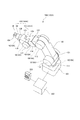
以下、本発明の第1実施形態に係るロボット装置500について、図1から図6を参照しながら説明する。まず、第1実施形態に係るロボット装置500の概略構成について、図1を参照しながら説明する。図1は、本発明の第1実施形態に係るロボット装置の概略構成を示す斜視図である。
<First Embodiment>
Hereinafter, a
図1に示すように、ロボット装置500は、産業用ロボットであり、ワークWの組み立て等の作業を行う多関節ロボット100と、多関節ロボット100を制御する制御装置200と、制御装置200に接続されたティーチングペンダント300と、を備えている。
As shown in FIG. 1, the
多関節ロボット100は、6軸多関節のロボットアーム101と、ロボットアーム101の先端に接続されたエンドエフェクタ102と、を備えている。
The articulated
ロボットアーム101は、作業台に固定されるベース部103と、変位や力を伝達する複数のリンク121〜126と、複数のリンク121〜126それぞれを旋回又は回転可能に連結する複数の関節111〜116と、を備えている。複数の関節111〜116それぞれは、不図示の駆動モータと、駆動モータの回転軸の回転角度を検出する不図示のエンコーダと、駆動モータのトルクを増大させるために駆動モータの出力を減速する減速機10と、を備えている。なお、駆動モータと減速機10とは、アクチュエータを構成しており、減速機10については、後に詳しく説明する。
The
エンドエフェクタ102は、ワークWを把持する把持爪104と、把持爪104を駆動する不図示の駆動モータと、駆動モータの回転角度を検出する不図示のエンコーダと、駆動モータの出力を減速する不図示の減速機と、を備えている。また、エンドエフェクタ102は、把持爪104等に作用する応力(反力)を検出可能な不図示の力覚センサを備えている。
The
ティーチングペンダント300は、ロボットアーム101やエンドエフェクタ102を駆動制御する際の指示を入力可能になっている。制御装置200は、ティーチングペンダント300から入力された設定等に基づいて、不図示の記憶装置に記憶された各種プログラム等に従って、ロボットアーム101やエンドエフェクタ102を駆動制御する。
The
上述のように構成されたロボット装置500は、入力された設定等に従って、制御装置200がロボットアーム101の複数の関節111〜116それぞれの駆動モータを減速させながら駆動することでエンドエフェクタ102を任意の3次元位置に移動させる。そして、任意の3次元位置で、把持爪104に作用する応力を力覚センサで検出しながらエンドエフェクタ102にワークWや部品を把持させて、ワークWの組み立て等の作業を行う。
The
次に、第1実施形態に係る減速機10について、図2から図6を参照しながら説明する。まず、減速機10の概略構成について、図2及び図3を参照しながら説明する。図2は、第1実施形態に係る減速機10を説明するための図である。図3は、第1実施形態に係る減速機10の減速歯車機構を示す図である。
Next, the speed reducer 10 according to the first embodiment will be described with reference to FIGS. First, a schematic configuration of the
図2に示すように、減速機10は、駆動モータに接続される入力軸2と、複数のリンク121〜126それぞれに接続される出力軸50とを備えており、駆動モータから入力される回転を減速して複数のリンク121〜126それぞれに伝達する。入力軸2は、軸受31,32を介して第2ケース35に軸支されており、出力軸50は、入力軸2と同軸になるように、軸受51,52を介して第1ケース30に軸支されている。
As shown in FIG. 2, the
また、減速機10は、歯数がZで歯面が円環状に形成された第1歯車3と、歯数がZ+1(第1歯車3との歯数差nが1)で歯面が円環状に形成された第2歯車4と、を備えている。第1歯車3は、所定高さよりも先端側に形成される歯先部と、所定高さよりも歯元側で歯先部同士の間に形成される凹状部と、を複数有する歯面が円環状に形成されており、第1ケース30に固定されている。第2歯車4は、所定高さよりも先端側に形成される歯先部と、所定高さよりも歯元側で歯先部同士の間に形成される凹状部と、を第1歯車よりも多い数有する歯面が円環状に形成されている。また、第2歯車4は、第1歯車3に対して所定角度傾斜して噛み合わされた状態で、入力軸2に設けられた傾斜軸部26に軸受61を介して回転自在に軸支されている。また、第2歯車4は、板バネ9を用いた撓み継手機構により与圧が与えられた状態で出力軸50に接続されており、バックラッシュを防止しながら噛み合っている公転成分のみが出力軸50に伝達されるようになっている。
Further, the
第1歯車3と第2歯車4とは、歯先部と凹状部とが最も深く噛合う最噛合い位置、最噛合い位置の反対側で歯先部同士がすれ違うすれ違い位置、を形成し得るように、第1歯車3の歯面と第2歯車4の歯面とが所定角度傾斜した状態で配置されている。同様に、第1歯車3と第2歯車4とは、すれ違い位置の両側で歯先部同士が接触する第1噛合い領域、第1噛合い領域よりも最噛合い位置側で互いの歯先部と凹状部とが接触する第2噛合い領域、を形成し得るように、所定角度傾斜して配置されている。
The
具体的には、第1歯車3の歯36と第2歯車4の歯46とは、半ピッチ位相がずれて配置されており、図3(a)に示す基準位相(最噛合い位置)では、第1歯車3の歯36と第2歯車4の歯46とは、半ピッチ位相がずれて深く噛み合っている。また、図3(b)に示す基準位相に対して±90度(第1噛合い領域と第2噛合い領域との境界位置)の近傍では、第1歯車3の歯36と第2歯車4の歯46とは、1/4ピッチ位相がずれて浅く噛み合っている(例えば、歯先部同士が1点で接触する)。
Specifically, the
更に、図3(c)に示す基準位相に対して±180度(すれ違い位置)では、第1歯車3の歯36と第2歯車4の歯46とは、同位相となって歯先部の先端同士が接触している。そして、これらの間の位相においては、徐々に歯36と歯46とが位相を変化させて噛み合い深さを変化させることで、第1歯車3の歯36と第2歯車4の歯46とは、ほぼ全周において接触するようになっている。
Furthermore, at ± 180 degrees (passing position) with respect to the reference phase shown in FIG. 3 (c), the
ここで、第1歯車3及び第2歯車4のほぼ全周において、第1歯車3の歯36と相手側である第2歯車4の歯46とが接触する原理について、図4を参照しながら説明する。図4は、減速歯車機構の凸歯型曲線を求めるための説明図である。
Here, the principle that the
図4に示すように、第1歯車3の入力回転軸70をZp軸、第2歯車4の傾斜回転軸71をZq軸とし、Zq軸のZp軸に対する傾斜角度をη、基準点72を原点O、Zp軸,Zq軸を含む面と直交する方向に共通のX軸をとる。そして、XYpZp座標系と、XYqZq座標系と、を設定する。すると、第1歯車3及び第2歯車4を半径Rとしたときの交差断面の外周が楕円Sとなる。
As shown in FIG. 4, the
次に、XYp面、XYq面上の半径Rの円周(基準ピッチ円と呼ぶ)上をYp軸、Yq軸上から時計回りに等速運動する点P,Q(歯の基準点と呼ぶ)を考え、楕円S上を運動する点C、点CからXYp面、XYq面に下ろした垂線の足を点P´,Q´とする。第1歯車3の歯数をZ、第2歯車4の歯数をZ+n(歯数差n=1)とすると、点Pの位相は、φp=2πt/Z(t:媒介変数)と表すことができ、点Qの位相は、φq=2πt/(Z+1)(t:媒介変数)と表すことができる。
Next, points P and Q (referred to as tooth reference points) that move at a constant speed clockwise from the Yp axis and Yq axis on the circumference of the radius R (referred to as a reference pitch circle) on the XYp plane and the XYq plane. In consideration of the above, let the point C ′ moving on the ellipse S and the legs of the perpendicular line from the point C to the XYp plane and XYq plane be points P ′ and Q ′. When the number of teeth of the
ここで、点P´,点Q´の位相を、共に、φc=2πt/(Z+1/2)とする。そして、点P,点Qを原点とする円柱面上の移動座標系xpyp,xqyqを考える。これらの座標系上で点Cの描く軌跡は、(2πt/(Z(Z+1/2)),Rtan(η/2)cos(2πt/(Z+1/2)))、(−2πt/((Z+1)(Z+1/2)),−Rtan(η/2)cos(2πt/(Z+1/2)))となる。即ち、yp=Rtan(η/2)cos(xpZ)、yq=−Rtan(η/2)cos(xq(Z+1))である。これを第1歯車3と第2歯車4の歯型とすると、点Cを噛み合い点として連続して接触させることができる。つまり、第1歯車3の歯36と第2歯車4の歯46とを、ほぼ全周において接触させることができる。
Here, the phases of the point P ′ and the point Q ′ are both φc = 2πt / (Z + 1/2). A moving coordinate system xpyp, xqyq on a cylindrical surface with points P and Q as the origin is considered. The locus drawn by point C on these coordinate systems is (2πt / (Z (Z + 1/2)), Rtan (η / 2) cos (2πt / (Z + 1/2))), (−2πt / ((Z + 1 ) (Z + 1/2)), -Rtan (η / 2) cos (2πt / (Z + 1/2))). That is, yp = Rtan (η / 2) cos (xpZ), yq = −Rtan (η / 2) cos (xq (Z + 1)). If this is the tooth pattern of the
次に、第1歯車3の歯36の歯先部36aと、第2歯車4の歯46の凹状部46bと、を接触させる原理について、図5を参照しながら説明する。図5は、減速歯車機構の歯先部36aと凹状部46bとの噛み合い状態を示す図である。
Next, the principle of contacting the
上記に従って第1歯車3と第2歯車4の歯型を形成すると、図5(a)に示すように、Yp,Yq方向の位相(すれ違い位置)では、基準点(所定高さ)38,48から高さRtan(η/2)の歯先部36a、46a同士が噛合い点81で接するようになる。そして、すれ違い位置の両側からX軸方向に回るにつれて、図5(b)、図5(c)のように第1噛合い領域を推移する(歯先部36a、46a同士が1点接触)。しかし、X軸方向での境界位置の近傍(図6(c)参照)までの歯先部36a、46aは凸形状であるが、これより歯元側の凹状部36b、46bは上述のコサイン関数は凹形状になっており、干渉が起きる。そこで、本実施形態では、境界位置の近傍での噛み合い点81を噛み合い基準点(基準位置)とする。そして、これより歯元側の凹状部36b、46bの歯型曲線は、噛み合い基準点より先端側の歯先部36a、46aが互いの相手の歯先部36a、46aの周りを動く軌跡の外接線(通過領域に倣わせた凹形状)として求めた曲線としている。
When the tooth forms of the
そのため、図5(d)及び図5(e)に示すように、第2噛合い領域での噛み合い点は互いの歯先部36a、46aと凹状部36b、46bとが噛み合うので、接触点83,84で示す二点が同時に噛み合うようになる。なお、厳密にいえば、相互の歯先部36a、46aの凸歯型は同一円柱面上にあるわけではないので、歯型曲線と原点を結んだ曲面を歯型としてその外接曲面と円柱面の交線を歯元側の凹状部36b、46bの歯型としている。
Therefore, as shown in FIG. 5D and FIG. 5E, the meshing point in the second meshing region is such that the
このように、本実施形態に係る歯車機構の第1歯車3と第2歯車4とをほぼ全周にわたって接触させることで、伝達トルクが分担され、非常に大きな負荷容量を小型軽量の歯車機構で得ることができる。また、圧力角は、歯数Zを大きくするほど、傾斜角ηを大きくするほど小さくなるので、適切な圧力角を設定することが可能になる。更に、図5(a)から図5(e)に示すように、歯型は噛み合い基準点前後の曲線がほぼ直線に近い。特に噛み合い基準点より深く噛み合う位相では、歯先部と凹状部同士が2点でしかも凸面と凹面で噛み合うため、接触面圧が低くなる。したがって、歯面応力が小さく摩耗が少ない歯型である。
In this way, the transmission torque is shared by bringing the
また、図5(a)及び図5(e)付近の位相では圧力角が90度近くでトルク伝達に寄与しないので、この前後の一定の範囲では接触させないように歯先、歯元あるいは歯先と歯元の両方を切削して非接触となる形状にしてもよい。非接触とすることで損失トルクを減少させることができる。 5A and 5E, the pressure angle is close to 90 degrees and does not contribute to torque transmission. Therefore, the tooth tip, tooth root, or tooth tip should not be contacted within a certain range before and after this. It is also possible to cut both the tooth base and the non-contact shape. Loss torque can be reduced by non-contact.
また、噛み合い基準点での歯厚は上記の式から各歯のピッチ2π/Z、2π/(Z+1)の約1/4となっており、歯強度がほぼ等しくなっている。したがって、どちらか弱いほうによって負荷トルクが制限されることがなく最適なバランスが得られる。尚、歯先部の歯型を求めるための点Cの位相角度φcは、前述の式に限らない。例えば、φc=(2Z+1)πt/(Z(Z+1))とすれば、yp=Rtan(η/2)cos(xp(Z+1/2)),yq=−Rtan(η/2)cos(xq(Z+1/2))となり、両歯車の噛み合い基準点での歯厚を等しくできる。その他、φp>φc>φqで連続でさえあればよい。 Further, the tooth thickness at the meshing reference point is about ¼ of the pitch 2π / Z, 2π / (Z + 1) of each tooth from the above formula, and the tooth strength is almost equal. Therefore, the load torque is not limited by the weaker one, and an optimal balance can be obtained. Note that the phase angle φc of the point C for obtaining the tooth shape of the tooth tip portion is not limited to the above formula. For example, if φc = (2Z + 1) πt / (Z (Z + 1)), then yp = Rtan (η / 2) cos (xp (Z + 1/2)), yq = −Rtan (η / 2) cos (xq ( Z + 1/2)), and the tooth thickness at the meshing reference point of both gears can be made equal. In addition, it is sufficient if φp> φc> φq.
以上の説明は、歯数差nが1の場合についてのものであるが、歯数差nを2とした場合についても、例えば、±180/n度の範囲にわたって連続的に噛み合う歯車機構を実現可能である。ただし、歯数差nが大きいと、通常の歯車機構と噛み合う歯数が変わらなくなってしまうので、歯数差nは、1又は2が好ましい。 The above description is for the case where the tooth difference n is 1. However, even when the tooth difference n is 2, for example, a gear mechanism that continuously meshes over a range of ± 180 / n degrees is realized. Is possible. However, if the tooth number difference n is large, the number of teeth meshing with a normal gear mechanism will not change, so the tooth number difference n is preferably 1 or 2.
次に、上述した歯車機構を有する減速機10による減速動作について、図2を援用して説明する。まず、入力軸2が1回転すると、傾斜軸部26が傾斜回転軸71を中心に回転し、傾斜回転軸71と入力回転軸70の交点である基準点72の周りを第2歯車4が1回揺動運動する。このとき、第1歯車3と第2歯車4との歯数差の角度だけ第2歯車4が公転する。即ち、入力軸2がZ+1回転すると、第2歯車4が1回転公転する。これにより、たわみ継ぎ手機構を介して出力軸50が1回転するので、1/(Z+1)に減速されたことになる。例えば、Z=49の場合、減速比1/50が得られる。このように、本発明の歯車機構を組み込んだことにより、高性能な減速機構を実現することができる。
Next, the speed reduction operation by the
なお、第1歯車3と第2歯車4とを入れ替えた場合、出力が逆転し、−1/Zの減速比が得られることはいうもでもない。また、本実施形態においては、各軸受に予圧を与えて剛性を高め、歯車間にも一定の予圧を与えるように高精度に組立てることでバックラッシュを最小にし、剛性を高めているが、各軸の軸受は、コロ軸受けやすべり軸受けなどの軸受を適用することができる。また、たわみ継ぎ手機構の例を示したが、代わりにジンバル機構や等速ジョイントなどの自在継ぎ手など、各種のカップリングを使用してもよい。
In addition, when the
また、上述の減速機10は、入力回転数を高くすると振動が生じる場合がある。これは、入力軸2の傾斜軸部26、軸受61及び第2歯車4からなる揺動部の重心が入力回転軸70から偏心している(基準点72より傾斜回転軸71上紙面右方向にずれている)ためである。従って、例えば、図6に示すように、揺動部の重心を基準点72の位置か、少なくとも入力回転軸70上になるようカウンターウェイト等を設ければよい。
In addition, the
例えば、図6(a)及び(b)は、カウンターウェイト65を設けて重心を入力回転軸70上とした例を示している。他の方法としては、後述の球面モデルによって実現した緯度オフセットによる頂角が180度でない歯車機構を用いて基準点72を紙面右方向にずらすことで揺動部の重心と一致させることもできる。この場合、余分なカウンターウェイトを設けるよりも軽量化、小型化が可能となる。さらに、図6(c)及び(d)は、第2カウンターウェイト66を逆位相に加えることで、いわゆる二面バランス状態とした例を示している。この場合、揺動運動による振動も抑えることができるので、さらに高速回転入力が可能になる。
For example, FIGS. 6A and 6B show an example in which a
<第2実施形態>
次に、本発明の第2実施形態に係るロボット装置500Aについて、図1を援用すると共に、図7から図11を参照しながら説明する。第2実施形態に係るロボット装置500Aは、減速機が第1実施形態と相違する。そのため、第2実施形態においては、第1実施形態と相違する点、即ち、減速機を中心に説明し、第1実施形態と同様の構成については、同じ符号を付してその説明を省略する。
Second Embodiment
Next, a
図1に示すように、ロボット装置500Aは、ワークWの組み立て等の作業を行う多関節ロボット100Aと、制御装置200と、ティーチングペンダント300と、を備えている。多関節ロボット100Aは、6軸多関節のロボットアーム101Aと、エンドエフェクタ102と、を備えており、ロボットアーム101Aは、ベース部103と、複数のリンク121〜126と、複数の関節111〜116と、を備えている。複数の関節111〜116それぞれは、不図示の駆動モータと、不図示のエンコーダと、駆動モータのトルクを増大させるために駆動モータの出力を減速する減速機10Aと、を備えている。
As shown in FIG. 1, the
次に、第2実施形態に係る減速機10Aについて、図7から図11を参照しながら説明する。まず、減速機10Aの概略構成について、図7及び図8を参照しながら説明する。図7は、第2実施形態に係る減速機10Aを説明するための図である。図8は、第2実施形態に係る減速機10Aの減速歯車機構を示す図である。
Next, a
図7に示すように、第2実施形態に係る減速機10Aは、固定された第1歯車3Aと噛み合いながら揺動する第2歯車4Aに歯46Aだけでなく反対側に歯47Aを設け、第3歯車5Aと噛み合わせている。これら二組の歯車機構は、基準点72Aを共有するように緯度オフセットを設定した歯車機構の歯型とし、それぞれの歯数は歯36AをZ1、歯46AをZ1+1、歯47AをZ2+1、歯57AをZ2としている。
As shown in FIG. 7, the
第3歯車5Aは、出力軸50Aに直結されており、高剛性のクロスローラ軸受51Aに軸支されている。第2実施形態においては、二組の歯車機構の緯度オフセットをほぼ等しくすることで、入力軸の傾斜軸部26A、軸受61A,62A、第2歯車4Aからなる揺動部の重心を基準点72Aに一致させている。
The
図8に示すように、第1歯車3Aの歯36Aと第2歯車4Aの歯46Aとは、半ピッチ位相がずれて噛み合わされ、第2歯車4Aの歯47Aと第3歯車5Aの歯57Aとは、半ピッチ位相がずれて噛み合わされている。そのため、図8(c)に示す位置では、第1歯車3Aの歯36Aと第2歯車4Aの歯46Aとが半ピッチ位相がずれて深く噛み合い、第2歯車4Aの歯47Aと第3歯車5Aの歯57Aとは、同位相となって歯先部の先端同士が接触している。また、図8(b)に示す位置では、第1歯車3Aの歯36Aと第2歯車4Aの歯46Aとが1/4ピッチ位相がずれて浅く噛み合い、第2歯車4Aの歯47Aと第3歯車5Aの歯57Aとも、1/4ピッチ位相がずれて浅く噛み合っている。更に、図8(a)に示す位置では、第1歯車3Aの歯36Aと第2歯車4Aの歯46Aとが、同位相となって歯先の先端同士が接触し、第2歯車4Aの歯47Aと第3歯車5Aの歯57Aとは、半ピッチ位相がずれて深く噛み合っている。
As shown in FIG. 8, the
そして、これらの中間の位相においては、歯36Aと歯46Aと、及び歯47Aと歯57Aと、が位相を変化させて噛み合い深さを変化させることで、第1歯車3Aと第2歯車4Aと、第2歯車4Aと第3歯車5Aとが、ほぼ全周において接触するようになっている。
In these intermediate phases, the
ここで、第1歯車3Aの歯36Aと第2歯車4Aの歯46A、第2歯車4Aの歯47Aと第3歯車5Aの歯57Aが、ほぼ全周において接触する原理について、図9及び図10を参照しながら説明する。図9は、減速歯車機構の凸歯型曲線を求めるための説明図である。図10は、点Cの軌跡を半周分だけ示した図である。
Here, the principle that the
図9に示すように、入力回転軸70AをZp軸、傾斜回転軸71AをZq軸とし、基準点72Aを原点O、Zp軸,Zq軸を含む面と直交する方向に共通のX軸をとり、XYpZp座標系と、XYqZq座標系と、を設定する。第2実施形態においては、円柱ではなく原点Oを中心とした半径Rの球体を考える。
As shown in FIG. 9, the input
次に、各座標系の赤道面であるXYp面、XYq面に対して緯度オフセットkp,kqにある小円(基準ピッチ円と呼ぶ)上をYp軸、Yq軸方向から時計回りに等速運動する点P,Q(歯の基準点と呼ぶ)を考える。第1歯車3Aの歯数をZとし、第2歯車4Aの歯数をZ+n(n=1)とすると、点P,Qの経度はφp=2πt/Z,φq=2πt/(Z+1)(t:媒介変数)と表すことができる。
Next, on the XYp plane, which is the equator plane of each coordinate system, and on the small circle (referred to as the reference pitch circle) at latitude offsets kp, kq with respect to the XYq plane, move at a constant speed clockwise from the Yp axis and Yq axis directions. Consider points P and Q (referred to as tooth reference points). When the number of teeth of the
ここで、点P,Qを結ぶ大円の円弧Lの点Cを噛み合い点として、点P,Qを原点とする球面上の移動座標系xpyp,xqyq上で点Cの描く軌跡を求める。前述の円柱モデルの場合と同様に、これを歯先部の凸形状とし、噛み合い基準点より噛み合いが深い側の歯型曲線は歯先部の凸形状の描く軌跡の外接曲線(凹形状)とすれば、ほぼ全周にわたって噛み合う歯型が得られる。この球面モデルの場合も噛み合い状態を表す図は、図5(a)〜(e)のようになる。なお、移動座標系xpypとxqyqが同一球面上にあるので、外接曲面でなく、外接曲線で考えても厳密な解が得られる。 Here, the locus drawn by the point C on the moving coordinate system xpyp, xqyq on the spherical surface with the points P, Q as the origin is obtained with the point C of the great circular arc L connecting the points P, Q as the meshing point. As in the case of the cylindrical model described above, this is the convex shape of the tooth tip, and the tooth profile curve on the side deeper than the mesh reference point is the circumscribed curve (concave shape) of the locus drawn by the convex shape of the tooth tip. If it does, the tooth type | mold which mesh | engages over a perimeter is obtained. In the case of this spherical model, the diagrams showing the meshing state are as shown in FIGS. Since the moving coordinate systems xpyp and xqyq are on the same spherical surface, a strict solution can be obtained even when considering the circumscribed curve instead of the circumscribed curved surface.
なお、具体的な歯先部の歯型曲線は前述の円柱モデルの場合のような単純な式で表すことはできず、煩雑になるので記述しないが、点Cの座標を求めて点P,Qの座標との差を求めればよい。ここでは結果の一例を示す。図10(a)及び(b)は、歯数Z=49、Z+1=50、傾斜角η=4度、緯度オフセットkp=kq=−8度の時のxpyp、xqyq上の点Cの軌跡を半周分だけ示したものであって、横軸がxp,xq、縦軸がyp,yqで単位はラジアンである。重ねて示したコサイン関数の歯型に比べて、かなり歯先(0度付近)が太い形状である。また、点Cを円弧の中点としたので、二つの歯先部の歯型は等しい形状となり、強度が均等である。点Cを円弧の等比分割点とするなどして、異ならせることもできる。例えば、歯数の逆数比とすれば、相似形の歯型が得られる。 It should be noted that the tooth profile curve of the specific tooth tip portion cannot be expressed by a simple expression as in the case of the above-described cylindrical model, and is not described because it is complicated, but the coordinates of the point C are obtained to obtain the points P, What is necessary is just to obtain | require the difference with the coordinate of Q. Here, an example of the result is shown. FIGS. 10A and 10B show the locus of point C on xypp and xqyq when the number of teeth Z = 49, Z + 1 = 50, the inclination angle η = 4 degrees, and the latitude offset kp = kq = −8 degrees. Only a half circle is shown, the horizontal axis is xp, xq, the vertical axis is yp, yq, and the unit is radians. Compared with the cosine function tooth shape shown in a superimposed manner, the tooth tip (near 0 degrees) is considerably thicker. In addition, since the point C is the midpoint of the arc, the tooth shapes of the two tooth tips have the same shape and the strength is uniform. It is also possible to make the points C different by, for example, making the point C into equal proportion division points. For example, if the reciprocal ratio of the number of teeth is used, a similar tooth shape is obtained.
噛み合い状態の推移は円柱モデルの場合と同様に、経度0度方向では歯先の先端が接触し、回り込むにつれて歯先の凸部が噛み合い点81で噛み合い、±90度方向の近傍で図5(c)の状態から接触点83,84で噛み合う図5(d)のような噛み合い状態になる。そして、最も深く噛み合う±180度方向では、図5(e)の状態になる。
As in the case of the cylindrical model, the transition of the meshing state is such that the tip of the tooth tip contacts in the 0 degree longitude direction, and the convex part of the tooth tip meshes at the
なお、前述のように緯度オフセットを与えた場合は歯型がコサイン歯型からある程度太くなったり細くなったりする。このため、図5(c)の一点噛み合いから2点噛み合いに推移する位相は90度方向から10度以上異なる場合もあるが、本発明の主旨は、そのような場合を含めて90度方向の近傍(境界位置の近傍)と称するものである。 In addition, when the latitude offset is given as described above, the tooth shape becomes somewhat thicker or thinner than the cosine tooth shape. For this reason, the phase of transition from the one-point meshing to the two-point meshing in FIG. 5 (c) may differ by more than 10 degrees from the 90-degree direction, but the gist of the present invention is that the 90-degree direction includes such a case. This is referred to as the vicinity (the vicinity of the boundary position).
このように、球面モデルによって緯度オフセットを設定することが可能になり、歯車の頂角が180度でないものを実現できるので、本発明の優れた性能を有する歯車機構の設計自由度が増す。 Thus, it becomes possible to set the latitude offset by the spherical model and realize a gear whose apex angle is not 180 degrees, so that the degree of freedom of design of the gear mechanism having the excellent performance of the present invention is increased.
また、本発明の歯車機構は、様々な機構装置に組み込んで使用できる。例えば、図12に示すような平行オフセット配置の機構がある。入力軸301と中間軸401の間に歯車機構361,461を設け、中間軸401と出力軸302の間に歯車機構362,462を設けたものである。歯車機構361,461と歯車機構362,462とに同じものを用いれば、入力軸と出力軸は平行で回転数は同一になる。もちろん、入力軸と出力軸の関係が平行でない場合や回転数が異なっても良い場合、それらの設計条件に合わせて本発明を適用すればよい。例えば、これを船舶のエンジンとスクリューの軸高さの差を吸収する伝達機構に使用すれば、従来の歯車機構やユニバーサルジョイントを使用するよりも直径を小さくでき省スペースで軽量、低コストが可能になる。
Further, the gear mechanism of the present invention can be used by being incorporated into various mechanism devices. For example, there is a mechanism of parallel offset arrangement as shown in FIG.
次に、上述した2組の歯車機構を有する減速機10Aによる減速動作について、図7及び図8を援用して説明する。まず、入力軸2が1回転すると、第2歯車4Aが1回揺動運動する。このとき、第2歯車4Aは固定された第1歯車3Aに対して360/(Z1+1)だけ公転する。一方、第3歯車5Aと第2歯車4Aとの間にも揺動による公転が生じる。すなわち、この構成は第2歯車4Aの公転を第2の歯車機構で取り出すようにした構成である。このようなタイプの減速比は、1−(Z1(Z2+1))/((Z1+1)Z2)で計算できることが知られている。例えば、Z1=24、Z2=48の時、1/50の減速比が得られる。また、例えば、Z1=48、Z2=49とすれば、1/2401という大減速比も可能であり、このタイプの減速機は、1/20程度の低減速比から数千分の1という大減速比まで、広い範囲の減速比を一段で実現することが可能になる。
Next, the speed reduction operation by the
本実施形態の場合、二組の歯車機構の緯度オフセットをほぼ等しくすることで、入力軸の傾斜軸部26A、軸受61A,62A、第2歯車4Aからなる揺動部の重心を基準点72Aに一致させることが容易となる。したがって、例えば、カウンターウェイトなどを使用しなくても高い入力回転数で使用することができる。
In the case of the present embodiment, by making the latitude offsets of the two sets of gear mechanisms substantially equal, the center of gravity of the swinging portion composed of the
更に、高い数千rpmというような高速で使用する場合は、二面でバランスを修正する必要がある。図11は、二つのほぼ同一形状のカウンターウェイト68、69を設けて二面バランス状態とした減速機である。このようにすれば、高速で使用しても振動が最小限に抑えられ、入力軸の軸受31A、32Aの寿命も伸ばすことができる。
Furthermore, when using at a high speed of several thousand rpm, it is necessary to correct the balance on two sides. FIG. 11 shows a speed reducer in which two
また、図7(b)に示すように、第1歯車3A及び第3歯車5Aは、高剛性な形状であるのに対して、第2歯車4Aは、高剛性の歯部の内周部に薄肉のフランジを設けている。これにより、第1歯車3Aと第3歯車5Aとで第2歯車4Aを挟み込んで予圧を与えた場合や各歯の誤差などを、このフランジ部の変形で吸収できるようになっている。つまり、本実施形態においては、減速機として必要な剛性に応じてこのような可撓性を与えることが可能としている。
In addition, as shown in FIG. 7B, the
更に、図8に示すように、二組の歯車機構は全周にわたって噛み合っており、第3歯車5Aにかかる負荷トルクは歯57A〜歯47A、46Aを介して第1歯車3Aの歯36Aに同位相で直接伝達される。したがって、非常に高い剛性が得られることがわかる。なお、本実施形態においては、歯36Aの歯数をZ1、歯46AをZ1+1、歯47AをZ2+1、歯57AをZ2、として正転差動出力としたが、歯36AをZ1+1、歯46AをZ1、歯47AをZ2、歯57AをZ2+1、として逆転差動出力とした場合も同様である。
Further, as shown in FIG. 8, the two sets of gear mechanisms mesh with each other over the entire circumference, and the load torque applied to the
また、歯36AをZ1、歯46AをZ1+1、歯47AをZ2、歯57AをZ2+1とすれば、差動でなく公転角が加算されることになる。この場合は、減速比があまり高くできず、第3歯車5Aにかかる負荷トルクが歯57A〜逆位相の歯36Aに伝達されることになり、差動の場合ほど高い剛性は得られないが、比較的低減速比で高い負荷容量の減速機に適用することができる。また、歯型の誤差や組立誤差などによる片当たりを軽減するために行なうクラウニング加工などは、本実施形態に係る歯型においても有効である。
Further, the
本実施形態の歯車機構では、多数の歯でトルクを分担できるので、例えば、歯車材として高性能鋼を使用すれば高性能な減速機が実現できる。なお、歯車材としては、低コストの一般鋼でもよく、非鉄金属や焼結材、樹脂なども適用可能なことはいうまでもない。 In the gear mechanism of the present embodiment, torque can be shared by a large number of teeth. For example, if high performance steel is used as the gear material, a high performance reduction gear can be realized. Needless to say, the gear material may be low-cost general steel, and non-ferrous metals, sintered materials, resins, and the like are also applicable.
以上説明したように、本実施形態によれば、二つの歯車の少なくとも一方の凸面状の歯先部が相手の歯元側の凹状部の歯型と連続的に噛み合うようにしたので、基準位相から±90度方向付近までの多数の歯同士が噛み合う。しかも、歯数と傾斜角に応じて噛み合い基準点での圧力角が自由に設定できるため、負荷容量を非常に大きくでき、適切な圧力角とすることで効率も改善できる。また、歯型の誤差が平均化されるため高い回転精度が得られ、凸面状の歯先部の歯型のツールを用いて加工が行なえるので歯型の創成加工も容易となる。 As described above, according to the present embodiment, since the convex tooth tip portion of at least one of the two gears continuously meshes with the tooth shape of the concave portion on the other tooth base side, the reference phase And a large number of teeth in the vicinity of ± 90 degrees direction mesh with each other. Moreover, since the pressure angle at the meshing reference point can be freely set according to the number of teeth and the inclination angle, the load capacity can be greatly increased, and the efficiency can be improved by setting the pressure angle appropriately. In addition, since the tooth pattern errors are averaged, high rotational accuracy is obtained, and the processing can be performed using the tooth-shaped tool of the convex tooth tip portion, so that the tooth mold can be easily created.
更に、歯先部の凸面状の歯型の歯厚をほぼ等しくすることで、噛み合う両方の歯の形状がほぼ同等になり、強度を確保できる。また、二つの歯車の基準円錐面の頂角を異ならせることで、二つの歯車の軸の交差点と歯面の位置関係を自由に変更できるので、設計の自由度が増す。 Furthermore, by making the tooth thickness of the convex tooth shape of the tooth tip portion substantially equal, the shapes of both teeth engaged with each other are substantially equal, and the strength can be secured. Also, by making the apex angles of the reference conical surfaces of the two gears different, the positional relationship between the intersections of the shafts of the two gears and the tooth surfaces can be freely changed, thereby increasing the degree of freedom in design.
また、2組の歯車機構(揺動歯車機構)を備えた(1組以上備えた)減速機を用いることで、多数の歯の噛み合いによる前述の効果により、高剛性、大トルク容量かつ小型軽量な減速機が実現可能になる。さらに、第1歯車と第3歯車に両端面で噛み合って揺動回転する第2歯車からなる歯車機構に第1実施形態に係る歯車機構を2組使用することで、さらに高剛性、大トルク容量かつ小型軽量な減速機が実現可能になる。 In addition, by using a reduction gear equipped with two sets of gear mechanisms (one or more sets of swinging gear mechanisms), high rigidity, large torque capacity, small size and light weight can be obtained due to the above-described effects of meshing of a large number of teeth. A simple reduction gear can be realized. Further, by using two sets of the gear mechanism according to the first embodiment in the gear mechanism composed of the second gear that is engaged with the first gear and the third gear at both end faces to rotate and rotate, the rigidity and the large torque capacity are further increased. In addition, a small and light reduction gear can be realized.
なお、第2実施形態においては、2組の歯車機構を有する減速機10Aを用いて説明したが、本発明においては、これに限定されない。減速機は、例えば、歯車機構を1組以上備えた減速機であってもよい。
In the second embodiment, the
3、3A 第1歯車
4、4A 第2歯車
10、10A 減速機
36 歯
36a 歯先部
36b 凹状部
46 歯
46a 歯先部
46b 凹状部
101、101A ロボットアーム
500、500A ロボット装置
n 歯数差
3,
Claims (7)
前記所定高さよりも先端側に形成される歯先部と、前記所定高さよりも歯元側で前記歯先部同士の間に形成される凹状部と、を前記第1歯車よりも多い数有する歯面が円環状に形成された第2歯車と、を備え、
前記第1歯車と前記第2歯車とは、前記歯先部の1つと前記凹状部の1つとが最も深く噛合う最噛合い位置、前記最噛合い位置の反対側であって歯先部同士がすれ違うすれ違い位置、前記すれ違い位置の両側で歯先部同士が接触する第1噛合い領域、前記第1噛合い領域よりも最噛合い位置側で互いの歯先部と凹状部とが接触する第2噛合い領域、を形成し得るように、前記第1歯車の歯面と前記第2歯車の歯面とが所定角度傾斜した状態で配置され、
前記第1歯車及び前記第2歯車のそれぞれの歯先部は、前記第1噛合い領域で歯先部同士が1点で接触する形状に形成され、
前記第1歯車の回転軸をZp、前記第2歯車の回転軸をZq、ZpとZqとの交点を原点O、Zp及びZqを含む面と直交する共通の軸をX、ZpとXとに直交する軸をYp、ZqとXとに直交する軸をYqとして、XYpZp座標系と、XYqZq座標系と、を設定したとき、
前記第1歯車及び前記第2歯車の半径をR、ZqのZpに対する傾斜角度をη、前記第1歯車の歯数をZ、前記第2歯車の歯数をZ+nとすると、
前記第1歯車及び前記第2歯車の前記歯先部の形状は、
yp=Rtan(η/2)cos(xpZ),yq=−Rtan(η/2)cos(xq(Z+n))
に基づいて形成された、
ことを特徴とする歯車機構。 A tooth surface having a plurality of tooth tip portions formed on the tip side from a predetermined height and concave portions formed between the tooth tip portions on the tooth base side from the predetermined height was formed in an annular shape. A first gear;
There are more tooth tip portions formed on the tip side than the predetermined height and concave portions formed between the tooth tip portions on the tooth base side from the predetermined height, as compared with the first gear. A second gear having a tooth surface formed in an annular shape,
The first gear and the second gear are the most meshed position where one of the tooth tip portions and one of the concave portions are most deeply meshed with each other, and the tooth tip portions are opposite to the most meshed position. Passing positions, the first meshing area where the tooth tip portions contact each other at both sides of the passing position, and the tooth tip portion and the concave portion contacting each other at the most meshing position side of the first meshing area. A tooth surface of the first gear and a tooth surface of the second gear are arranged in a state inclined at a predetermined angle so as to form a second meshing region,
Each tooth tip portion of the first gear and the second gear is formed in a shape in which the tooth tip portions contact each other at one point in the first meshing region,
The rotation axis of the first gear is Zp, the rotation axis of the second gear is Zq, the intersection of Zp and Zq is the origin O, and the common axis orthogonal to the plane including Zp and Zq is X, Zp and X When an orthogonal axis is set to Yp, an axis orthogonal to Zq and X is set to Yq, and an XYpZp coordinate system and an XYqZq coordinate system are set,
When the radius of the first gear and the second gear is R, the inclination angle of Zq with respect to Zp is η, the number of teeth of the first gear is Z, and the number of teeth of the second gear is Z + n.
The shape of the tooth tip portion of the first gear and the second gear is:
yp = Rtan (η / 2) cos (xpZ), yq = −Rtan (η / 2) cos (xq (Z + n))
Formed based on the
A gear mechanism characterized by that.
前記第2歯車の凹状部は、前記第1歯車の歯先部が前記第2歯車の歯先部の周りを動く軌跡の外接線として求めた曲線で形成された、
ことを特徴とする請求項1に記載の歯車機構。 The concave portion of the first gear is formed by a curve obtained as a circumscribed line of a trajectory in which the tooth tip portion of the second gear moves around the tooth tip portion of the first gear,
The concave portion of the second gear is formed by a curve obtained as a circumscribed line of a locus in which the tooth tip portion of the first gear moves around the tooth tip portion of the second gear.
The gear mechanism according to claim 1.
ことを特徴とする請求項2に記載の歯車機構。 As for the shape of the tooth tip part of the first gear and the second gear, the tips contact at the passing position,
The gear mechanism according to claim 2.
ことを特徴とする請求項2に記載の歯車機構。 The shape of the tip portion of the first gear and the second gear was cut into a shape in which the tips are not in contact with each other at the passing position.
The gear mechanism according to claim 2.
ことを特徴とする請求項2から4のいずれか1項に記載の歯車機構。 The tooth number difference n between the first gear and the second gear is 1 or 2.
The gear mechanism according to any one of claims 2 to 4, wherein the gear mechanism is provided.
ことを特徴とする減速機。 One or more sets of the gear mechanism according to any one of claims 1 to 5, wherein the input rotation is decelerated and output.
A reduction gear characterized by that.
Priority Applications (5)
| Application Number | Priority Date | Filing Date | Title |
|---|---|---|---|
| JP2012210920A JP6140958B2 (en) | 2012-09-25 | 2012-09-25 | Gear mechanism, reducer and robot arm |
| CN201380054882.3A CN104755801B (en) | 2012-09-25 | 2013-09-20 | Gear mechanism, decelerator and mechanical arm |
| US14/422,881 US9427866B2 (en) | 2012-09-25 | 2013-09-20 | Gear mechanism, speed reducer, and robot arm |
| PCT/JP2013/076446 WO2014051131A1 (en) | 2012-09-25 | 2013-09-20 | Gear mechanism, speed reducer, and robot arm |
| EP13777345.3A EP2901041A1 (en) | 2012-09-25 | 2013-09-20 | Gear mechanism, speed reducer, and robot arm |
Applications Claiming Priority (1)
| Application Number | Priority Date | Filing Date | Title |
|---|---|---|---|
| JP2012210920A JP6140958B2 (en) | 2012-09-25 | 2012-09-25 | Gear mechanism, reducer and robot arm |
Publications (3)
| Publication Number | Publication Date |
|---|---|
| JP2014066280A JP2014066280A (en) | 2014-04-17 |
| JP2014066280A5 JP2014066280A5 (en) | 2015-11-12 |
| JP6140958B2 true JP6140958B2 (en) | 2017-06-07 |
Family
ID=49382556
Family Applications (1)
| Application Number | Title | Priority Date | Filing Date |
|---|---|---|---|
| JP2012210920A Active JP6140958B2 (en) | 2012-09-25 | 2012-09-25 | Gear mechanism, reducer and robot arm |
Country Status (5)
| Country | Link |
|---|---|
| US (1) | US9427866B2 (en) |
| EP (1) | EP2901041A1 (en) |
| JP (1) | JP6140958B2 (en) |
| CN (1) | CN104755801B (en) |
| WO (1) | WO2014051131A1 (en) |
Cited By (1)
| Publication number | Priority date | Publication date | Assignee | Title |
|---|---|---|---|---|
| AU2018306966B2 (en) * | 2017-07-27 | 2021-07-22 | Fujitsu General Limited | Rotary compressor |
Families Citing this family (15)
| Publication number | Priority date | Publication date | Assignee | Title |
|---|---|---|---|---|
| JP6429517B2 (en) * | 2014-07-10 | 2018-11-28 | キヤノン株式会社 | Gear mechanism, transmission, and articulated robot arm |
| JP6507605B2 (en) * | 2014-12-04 | 2019-05-08 | 三菱重工業株式会社 | Differential gear transmission |
| CN107250607B (en) * | 2015-03-02 | 2020-08-21 | Thk株式会社 | Speed reducing or increasing device |
| JP6611454B2 (en) * | 2015-04-09 | 2019-11-27 | キヤノン株式会社 | Swing gear mechanism, transmission, actuator, and robot arm |
| US9768664B2 (en) | 2015-05-21 | 2017-09-19 | The Boeing Company | Balanced eccentric gear design and method |
| US10203022B2 (en) * | 2015-11-04 | 2019-02-12 | The Boeing Company | Elliptically interfacing wobble motion gearing system and method |
| US10024391B2 (en) | 2016-01-06 | 2018-07-17 | The Boeing Company | Elliptically interfacing gearbox |
| US10574109B2 (en) | 2016-04-28 | 2020-02-25 | The Boeing Company | Permanent magnet biased virtual elliptical motor |
| US10215244B2 (en) | 2017-03-02 | 2019-02-26 | The Boeing Company | Elliptically interfacing gear assisted braking system |
| US10520063B2 (en) | 2017-04-21 | 2019-12-31 | The Boeing Company | Mechanical virtual elliptical drive |
| US10267383B2 (en) * | 2017-05-03 | 2019-04-23 | The Boeing Company | Self-aligning virtual elliptical drive |
| WO2020034373A1 (en) * | 2018-08-17 | 2020-02-20 | 北京智能大艾机器人科技有限公司 | Face tooth cycloid-pin gear pair and nutation speed reduction device |
| US10968969B2 (en) | 2019-03-18 | 2021-04-06 | The Boeing Company | Nutational braking systems and methods |
| US11459098B2 (en) | 2019-11-27 | 2022-10-04 | The Boeing Company | Variable speed transmission and related methods |
| CN112836319B (en) * | 2021-03-11 | 2022-07-22 | 西南交通大学 | Simulation method considering non-uniformly distributed tooth root crack fault |
Family Cites Families (11)
| Publication number | Priority date | Publication date | Assignee | Title |
|---|---|---|---|---|
| JPS4512664Y1 (en) * | 1966-08-29 | 1970-06-02 | ||
| IS988B6 (en) * | 1975-04-15 | 1978-03-08 | Balcke-Dürr AG. | Gear system |
| JPS5254854A (en) * | 1975-10-30 | 1977-05-04 | Hasetsuku Enjiniaringu Kk | Multiengaged wn gear |
| JPS54120347A (en) * | 1978-03-09 | 1979-09-18 | Buichi Nakamura | Skewed intermeshing differential face gearing mechanism |
| KR100189281B1 (en) * | 1994-12-27 | 1999-06-01 | 미따라이 하지메 | Speed reducer |
| US8210070B2 (en) * | 2009-05-22 | 2012-07-03 | National University Corporation Fukushima University | Modified crown reduction gear |
| CN101793309A (en) * | 2010-03-26 | 2010-08-04 | 傅元才 | Planet gear speed reducer with small tooth difference and power wrench with large torque |
| WO2011154981A1 (en) | 2010-06-11 | 2011-12-15 | Orbitech Engineering S.R.L. | Kinematism with orbital movement with fixed orientation |
| WO2011155071A1 (en) * | 2010-06-11 | 2011-12-15 | 国立大学法人福島大学 | Multi-degree-of-freedom manipulator |
| CN101915286B (en) * | 2010-08-30 | 2012-02-01 | 重庆大学 | Constrained speed reducer with small teeth difference |
| CA2863193C (en) * | 2012-11-13 | 2017-04-25 | National University Corporation Fukushima University | Crown gear deceleration mechanism |
-
2012
- 2012-09-25 JP JP2012210920A patent/JP6140958B2/en active Active
-
2013
- 2013-09-20 CN CN201380054882.3A patent/CN104755801B/en active Active
- 2013-09-20 EP EP13777345.3A patent/EP2901041A1/en not_active Withdrawn
- 2013-09-20 WO PCT/JP2013/076446 patent/WO2014051131A1/en active Application Filing
- 2013-09-20 US US14/422,881 patent/US9427866B2/en active Active
Cited By (2)
| Publication number | Priority date | Publication date | Assignee | Title |
|---|---|---|---|---|
| AU2018306966B2 (en) * | 2017-07-27 | 2021-07-22 | Fujitsu General Limited | Rotary compressor |
| US11225971B2 (en) | 2017-07-27 | 2022-01-18 | Fujitsu General Limited | Rotary compressor |
Also Published As
| Publication number | Publication date |
|---|---|
| US20150224642A1 (en) | 2015-08-13 |
| CN104755801A (en) | 2015-07-01 |
| US9427866B2 (en) | 2016-08-30 |
| EP2901041A1 (en) | 2015-08-05 |
| JP2014066280A (en) | 2014-04-17 |
| WO2014051131A1 (en) | 2014-04-03 |
| CN104755801B (en) | 2017-06-20 |
Similar Documents
| Publication | Publication Date | Title |
|---|---|---|
| JP6140958B2 (en) | Gear mechanism, reducer and robot arm | |
| TWI418452B (en) | A wrist unit for an industrial robot | |
| JP6305076B2 (en) | Gear mechanism, transmission, and articulated robot arm | |
| JP4970250B2 (en) | Turning structure used for wrist joint of industrial robot | |
| JP4696912B2 (en) | Industrial robot | |
| JP6297622B2 (en) | Link actuator | |
| JP2015209931A (en) | Undulation gear device and robot arm | |
| WO2013069533A1 (en) | Link operation device | |
| EP3470704B1 (en) | Link operating device | |
| JP6807078B2 (en) | Robot deceleration transmission device | |
| JP7089852B2 (en) | Link actuator | |
| JP6128797B2 (en) | Parallel link mechanism, constant velocity universal joint, and link actuator | |
| JP4388566B2 (en) | 3D cam mechanism | |
| JP6429517B2 (en) | Gear mechanism, transmission, and articulated robot arm | |
| CN107035820B (en) | Multi-degree-of-freedom pitch circle inner-meshing annular type movable transmission device | |
| JP2005127475A (en) | Link operating device | |
| JP2015224786A (en) | Parallel link mechanism and link activating device | |
| JP2015161382A (en) | Gear mechanism, speed change gear and multi-joint robot arm | |
| JP2016128708A (en) | Oscillation type speed reducer and robot arm | |
| WO2011155070A1 (en) | Parallel manipulator | |
| JPH11287303A (en) | Parallel link mechanism | |
| JP2023176206A (en) | Gear device, and robot | |
| JP4756360B2 (en) | Ball wheel drive mechanism | |
| JP2016200192A (en) | Oscillating gear mechanism, transmission, actuator, and robot arm | |
| EP1338388A2 (en) | Rotatable-and-swingable type of rotary joint device |
Legal Events
| Date | Code | Title | Description |
|---|---|---|---|
| A521 | Request for written amendment filed |
Free format text: JAPANESE INTERMEDIATE CODE: A523 Effective date: 20150924 |
|
| A621 | Written request for application examination |
Free format text: JAPANESE INTERMEDIATE CODE: A621 Effective date: 20150924 |
|
| A131 | Notification of reasons for refusal |
Free format text: JAPANESE INTERMEDIATE CODE: A131 Effective date: 20160913 |
|
| A521 | Request for written amendment filed |
Free format text: JAPANESE INTERMEDIATE CODE: A523 Effective date: 20161114 |
|
| TRDD | Decision of grant or rejection written | ||
| A01 | Written decision to grant a patent or to grant a registration (utility model) |
Free format text: JAPANESE INTERMEDIATE CODE: A01 Effective date: 20170404 |
|
| A61 | First payment of annual fees (during grant procedure) |
Free format text: JAPANESE INTERMEDIATE CODE: A61 Effective date: 20170502 |
|
| R151 | Written notification of patent or utility model registration |
Ref document number: 6140958 Country of ref document: JP Free format text: JAPANESE INTERMEDIATE CODE: R151 |