JP6010722B2 - Robot vacuum cleaner, dust discharge station and multi-stage cyclone vacuum cleaner - Google Patents
Robot vacuum cleaner, dust discharge station and multi-stage cyclone vacuum cleaner Download PDFInfo
- Publication number
- JP6010722B2 JP6010722B2 JP2011168849A JP2011168849A JP6010722B2 JP 6010722 B2 JP6010722 B2 JP 6010722B2 JP 2011168849 A JP2011168849 A JP 2011168849A JP 2011168849 A JP2011168849 A JP 2011168849A JP 6010722 B2 JP6010722 B2 JP 6010722B2
- Authority
- JP
- Japan
- Prior art keywords
- dust
- discharge
- container
- robot cleaner
- cleaner
- Prior art date
- Legal status (The legal status is an assumption and is not a legal conclusion. Google has not performed a legal analysis and makes no representation as to the accuracy of the status listed.)
- Expired - Fee Related
Links
Images


Description
本出願は、米国特許出願61/367723(出願日:2011年8月1日)の優先権を主張するものである。
This application claims priority from US
本発明は、塵埃を容易に排出することができるロボット掃除機及びその塵埃排出ステーションに関する。 The present invention relates to a robot cleaner capable of easily discharging dust and a dust discharge station thereof.
ロボット掃除機は、家屋の床を自律的に清掃し、従来の非ロボット掃除機の相当部分を置き換える非常に有用な機器であると期待されている。ロボット掃除機において塵埃の排出に対処する従来の方法がいくつか提案されている。 Robotic vacuum cleaners are expected to be very useful devices that autonomously clean the floor of a house and replace a substantial portion of conventional non-robot vacuum cleaners. Several conventional methods for dealing with dust discharge in robot cleaners have been proposed.
US5787545Bは、ロボット掃除機から塵埃を排出する排出ユニットを備えるシステムについて記載している。US7053578Bは、充電ステーションにおいて負圧を生成する吸引抽出アセンブリーを使用し、ロボット掃除機の底部から塵埃を排出するシステムについて記載している。US6076226B及びUS6327741Bは、中央処理装置によって駆動し、ロボット掃除機の上から塵埃を収集するシステムについて記載している。 US 5787545B describes a system comprising a discharge unit for discharging dust from a robot cleaner. US7053578B describes a system for discharging dust from the bottom of a robot cleaner using a suction extraction assembly that generates negative pressure at the charging station. US6072226B and US6327741B describe a system that collects dust from the top of a robot cleaner driven by a central processing unit.
上記の従来方式では比較的複雑な機器が内部に必要になり、ロボット掃除機中の塵埃を収集するためにステーションの一部において負圧を生成する必要があることが明白である。また、ユーザがステーションから塵埃を排出する方法は、ロボット掃除機に既に集められている塵埃にもかかわらず通常の掃除機に似ている。 Obviously, the above-described conventional method requires relatively complicated equipment inside, and it is necessary to generate a negative pressure in a part of the station in order to collect dust in the robot cleaner. Also, the method by which the user discharges the dust from the station is similar to a normal vacuum cleaner despite the dust already collected in the robot cleaner.
さらに、多段サイクロン掃除機内の塵埃を完全に排出するのは難しい。 Furthermore, it is difficult to completely discharge the dust in the multistage cyclone cleaner.
通常の非ロボット掃除機と比較して、ロボット掃除機は次の問題を有する。 Compared with a normal non-robot cleaner, the robot cleaner has the following problems.
(1)塵埃収容容量が小さいためにユーザによって頻繁な塵埃の排出が必要であること
(2)塵埃容器からの塵埃の排出を簡単にする必要があること
(3)吸引力が低いこと
(1) Since the dust storage capacity is small, it is necessary for the user to frequently discharge dust. (2) It is necessary to simplify the discharge of dust from the dust container. (3) The suction force is low.
上記の従来方式は、上記の問題のすべてを良好に解決することができない。 The above conventional method cannot satisfactorily solve all of the above problems.
本発明の目的は、上記の問題(1)〜(3)を良好に解決し、かつ、ユーザによる頻繁な塵埃の排出の必要性をなくし、ロボット掃除機に収集された塵埃を排出するための効率的な機器を提供することである。本発明は、さらに、塵埃を良好に排出することができる多段サイクロン掃除機を提供する。 An object of the present invention is to satisfactorily solve the above problems (1) to (3), eliminate the need for frequent dust discharge by a user, and discharge dust collected by a robot cleaner. It is to provide efficient equipment. The present invention further provides a multi-stage cyclone cleaner that can discharge dust well.
本発明の装置は、特許請求の範囲に記載の要素を有する。 The device of the present invention comprises the elements recited in the claims.
本発明の一態様に従って、自律的に動いて塵埃を収集し、かつ、塵埃排出ステーションへと塵埃を排出することができるロボット掃除機であって、塵埃を格納するための塵埃容器と、塵埃容器へ塵埃を収集するための塵埃入口と、ロボット掃除機の底面に設けられ、塵埃容器に収集された塵埃を排出するための塵埃容器の開閉機構とを有するロボット掃除機が提供される。 In accordance with one aspect of the present invention, a robot cleaner capable of autonomously collecting and collecting dust and discharging dust to a dust discharge station, a dust container for storing dust, and a dust container There is provided a robot cleaner having a dust inlet for collecting dust, and a dust container opening / closing mechanism provided on the bottom surface of the robot cleaner for discharging dust collected in the dust container.
本発明の一態様に従って、掃除機から塵埃を収集することができる塵埃排出ステーションであって、掃除機に対して台を提供し、掃除機を塵埃排出位置に配置するための掃除機用の台と、掃除機台にて設けられ、塵埃排出位置で掃除機から塵埃を受けるように適合している塵埃受けと、塵埃受けの下に配置され、かつ、ステーション内塵埃容器を保持するための容器ホルダーとを有し、塵埃排出ステーションは、少なくとも重力に起因して、掃除機によって収集された塵埃を掃除機から受け、かつ、塵埃受け及びステーション内塵埃容器によって塵埃の経路を提供することによるステーション内塵埃容器の中へ収容する塵埃排出ステーションが提供される。 In accordance with one aspect of the present invention, a dust discharge station capable of collecting dust from a vacuum cleaner, the base for the vacuum cleaner for providing a base for the vacuum cleaner and placing the vacuum cleaner in a dust discharge position A dust receiver that is provided at the vacuum cleaner stand and is adapted to receive dust from the cleaner at the dust discharge position, and a container that is disposed under the dust receiver and holds the dust container in the station And a dust discharge station for receiving dust collected by the cleaner from the cleaner due to at least gravity, and providing a dust path by the dust receiver and the dust container in the station. A dust discharge station is provided for receiving into the inner dust container.
本発明の一態様に従って、床の気体が入る入口、及び第1サイクロンの中央に気体の出口を有する、塵埃を分離するための第1サイクロンと、第1サイクロンより小さな塵埃を分離するための複数の第2サイクロンであって、第2サイクロンの各々は第1サイクロンより小さく、第1サイクロンの出口からの気体が第2サイクロンの入口へ供給される、第2サイクロンと、吹きつけ機、振動機構及び攪拌機からなる群から選択される塵埃容器の内部の塵埃の除去を促進させるための塵埃排出促進機構とを備えた多段サイクロン掃除機が提供される。 In accordance with one aspect of the present invention, a first cyclone for separating dust having an inlet for receiving gas in the floor and a gas outlet in the center of the first cyclone, and a plurality for separating dust smaller than the first cyclone. Each of the second cyclones, wherein each of the second cyclones is smaller than the first cyclone, and the gas from the outlet of the first cyclone is supplied to the inlet of the second cyclone, the blowing cyclone, and the vibration mechanism And a multistage cyclone cleaner provided with a dust discharge promoting mechanism for promoting the removal of dust inside a dust container selected from the group consisting of a stirrer.
図面を参照して本発明を説明する。同一又は類似の要素は同一又は類似の番号を割り当てている。 The present invention will be described with reference to the drawings. The same or similar elements are assigned the same or similar numbers.
(1)全体のシステム
図1は、本発明の一実施形態に従うロボット掃除機システム1の側面図を示している。
(1) Overall System FIG. 1 shows a side view of a
ロボット掃除機システム1は、ユーザの家屋の床5を清掃するためのロボット掃除機ステーション10及び自己推進可能なロボット掃除機50を備える。
The
ロボット掃除機ステーション10は、ロボット掃除機50のための充電ステーション及び塵埃排出ステーションとして機能し、ロボット掃除機50は、自律的に、又は遠隔制御装置によって命じられた場合にロボット掃除機ステーション10へと来る。
The
(2)ロボット掃除機ステーション10
ロボット掃除機ステーション10は、塵埃収集システム12と、及び塵埃収集システム12の上にバッテリー充電機30とを備える。バッテリー充電機30は、ロボット掃除機50内の二次電池52を充電するために接点端子32を有する。代わりに、バッテリー充電機30は、電磁場を誘導するコイルを使用する非接触帯電機器であってもよい。
(2) Robot
The
塵埃収集システム12は、ケーシング13、カバー16、塵埃壁18、導路21、ステーション内塵埃容器20、ホルダー片26を含む塵埃容器ホルダー(ホルダー:保持具)、上部ホルダー片ファスナー22及び下部ホルダー片ファスナー24(ファスナー:固定具)を備える。この場合、ステーション内塵埃容器20は、使用の都度廃棄されるプラスチック袋(ポリ袋)である。
The
ユーザが塵埃を扱わずにゴミ集積場へとプラスチック袋を廃棄することができるので、使い捨て可能なプラスチック袋の使用は有利である。代わりに、ステーション内塵埃容器20は、ユーザが使い捨て可能なプラスチック袋を内側にセットすることができる硬質プラスチック製の容器であってもよい。これによって、プラスチック袋が満杯になってもプラスチック袋が破裂しないので有利である。さらに、ステーション内塵埃容器20内の塵埃を収集するために、ステーション内塵埃容器20内にてサイクロン遠心システムを作るために気体ブローの流れが使用される場合において、ステーション内塵埃容器20の体積を制限できるという点でも有利でありうる。
The use of a disposable plastic bag is advantageous because the user can discard the plastic bag to the garbage dump without handling the dust. Alternatively, the in-
ステーション内塵埃容器20が満杯に近くなると、ユーザはゴミ集積場へとプラスチック袋を廃棄するためにステーション内塵埃容器ホルダーの係合を解除する。
When the in-
好ましくは、塵埃収集システム12の上面の高さは、ロボット掃除機50が塵埃収集システム12の上面に容易に戻ることができるように清掃する床5の高さと実質的に同一である。これを実現するために、塵埃収集システム12は複数のポール及び継ぎ目で作られる調節可能な脚を備える。これは様々なユーザの床に対して調節するという点で有利である。塵埃収集システム12は、ステーション内塵埃容器を収容するためにドア(図11のようなもの)を有してもよい。さらに、塵埃収集システム12には、階下への階段のステップで本システムをセットするための形状を有していてもよい。
Preferably, the height of the upper surface of the
(3)ロボット掃除機50
ロボット掃除機50は、人による操作を伴わずに、床5を単独で清掃する自己推進可能な自律的な掃除機である。同様のロボット掃除機の例には、iRobot社によってリリースされているRoomba(登録商標)シリーズがある。ロボット掃除機50は、ハウジング、3つのタイヤ62、塵埃入口54、掃除機内塵埃容器56、塵埃容器カバー66、塵埃壁受け64、塵埃フィルタ57、モータファンユニット61、及び気体出口を備える。
(3)
The
ロボット掃除機50は、モータファンユニット61によって生成された負圧を使用して、塵埃入口54を介して塵埃60を掃除機内塵埃容器56内に収集する。なお、塵埃とは、ロボット掃除機によって集められる対象のいかなる物質をも含む。
The
掃除機内塵埃容器56は通常の真空掃除機よりも小型である。なぜなら、小さな空間の場所を清掃するため、そして、電池を長持ちさせるために、ロボット掃除機50が小型であるからである。すなわち、一般に、ロボット掃除機においては通常の真空掃除機よりも、掃除機内塵埃容器56から塵埃を排出する必要性が厳しい。
The
モータファンユニット61のモータは、塵埃入口及び掃除機内塵埃容器56で負圧を生成するためにファンを回転させ、そしてフィルタ57を使用して気体から塵埃を分離することにより掃除機内塵埃容器56に塵埃を留めさせる。
The motor of the
代わりに、この分離は、後述するように遠心力を使用して気体から塵埃を分離するサイクロン機構を使用して行ってもよい。 Alternatively, this separation may be performed using a cyclone mechanism that separates dust from the gas using centrifugal force as described below.
二次電池によって動力がモータに供給される。したがって、ロボット掃除機50は、バッテリーを充電するためにロボット掃除機ステーション10を必要とする。
Power is supplied to the motor by the secondary battery. Therefore, the
(4)排出機構
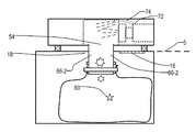
図2Aは、塵埃排出の際の図1のロボット掃除機システム1の側面図を示している。
(4) Discharge Mechanism FIG. 2A shows a side view of the robot
ロボット掃除機50がロボット掃除機ステーション10へ自律的に又はユーザによって運ばれて戻ると、充電機器がロボット掃除機50を充電し、掃除機内塵埃容器56に収められている塵埃を排出する。塵埃収集システム12の上面にあるカバー16が、自動的に又はユーザの操作によって開かれる。その後で、塵埃収集システム12は、開放気体へ塵埃が出るのを回避するためにロボット掃除機50の底面に接するように塵埃壁18を上昇させる。すなわち、塵埃壁18によって密封性を得る。この実施形態では、塵埃が開放気体に出ないことを確実にするために、塵埃壁18がロボット掃除機50の底面に形成された溝(図示せず)に入るように動く。
When the
一方、ロボット掃除機50は、塵埃を排出するためにカバー66を開く。塵埃壁18である塵埃受けが塵埃を受ける。少なくとも重力の影響で、塵埃収集システム12の導路21を介してステーション内塵埃容器20へと塵埃が下方へ落ちる。
On the other hand, the
この排出プロセスにおいて、塵埃入口弁58が閉じた状態で、ロボット掃除機50は、一又は複数の吹きつけ機(ブロワー)74を使用して気体を吹きつけてもよい。図2Bは、閉状態の塵埃入口弁58を詳細に示している。好ましくは、塵埃入口弁58は、気体路を一方向に開く一方向機構を有する。好ましくは、この一方向機構は、一又は複数のヒンジを使用する。これは、掃除機内塵埃容器56に負圧があり、かつ、吹きつけ機74が吹きつけしていない場合にのみ気体路を開く。図2Bにおいて、塵埃入口弁58は、2つのプレート58B及び2つのヒンジ58Aを有し、これらの2つのプレート58Bは、2つのプレート58Bの間の密封性を高めるために重なり合っている領域58Cを形成している。
In this discharge process, the
吹きつけ機74の吹きつけエネルギーは、吹きつけ機74専用の吹きつけ機構を使用して供給されうる。好ましくは、0.1秒〜5秒のパルスを形成するように気体を吹きつける。これは、吹きつける気体の総量を減らして、吹きつけ力を向上させ、ステーション内塵埃容器20が破裂するのを防ぎ、エネルギーを節約するためである。代わりに、吹きつけ機74の吹きつけエネルギーは、塵埃を完全に排出するためにモータファンユニット61を使用して供給されうる。これは、弁機構を使用してモータからフィルタ57への気流のほとんどを止め、モータから掃除機内塵埃容器56の中に入る気体路に対する弁72を開き、そして、モータファンユニット61におけるファンを逆回転させることによって、達成されうる。したがって、掃除機内塵埃容器56側からフィルタ57に付着した塵埃を、掃除機内塵埃容器56に戻るように吹き飛ばすことができる(図3Aを参照)。
The spraying energy of the
図3Aでは、弁72は、ファン61Aに対してフィルタ57側に設けられる。代わりに、ファン61Aに対して、最終フィルタ57Bが位置する気流の出口の側に、弁72が設けられていてもよい。この場合、ロボット掃除機50は、最終フィルタ57Bの近傍又は最終フィルタ57B自身において付着する小さな塵埃を弁72及び吹きつけ機74を介して塵埃容器56へと吹き飛ばす機構を有することができる。
In FIG. 3A, the
さらに、ロボット掃除機50は排出プロセスを支援するように、ロボット掃除機50自身を振動してもよい。この振動は、電動の振動装置によって行ってもよく、タイヤを使用して、ロボット掃除機50を何度も前進及び後退させて又はタイヤを振動させて行ってもよく、あるいはロボット掃除機50をロボット掃除機ステーション10における壁に打ち付けることによって行ってもよい。
Further, the
ロボット掃除機50は、掃除機内塵埃容器56内の塵埃を除去するための攪拌機(アジテータ)を有してもよい。好ましくは、攪拌機は、長さ100mm・直径0.3mmの合成樹脂繊維の(10本の)束を有する。図16における攪拌機19−3を参照のこと。攪拌機は、鞭のように動くように回転し、これによって、掃除機内塵埃容器の内部の壁に付着する塵埃が取り除かれる。
The
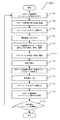
図4は、排出プロセスの流れ図を示している。ロボット掃除機ステーション10は、ロボット掃除機50がステーションに戻るのを待つ(ステップ302)。ステーション、ロボット掃除機及び/又はユーザが、ロボット掃除機を排出位置に配置する(ステップ304)。ステーション、ロボット掃除機、及び/又はユーザが、ステーションのカバーを開く(ステップ306)。ステーション、ロボット掃除機、及び/又はユーザは、ステーションの塵埃壁を上昇させる(ステップ308)。ステーション、ロボット掃除機、及び/又はユーザは、ロボット掃除機のカバーを開き、塵埃入口弁を閉じ、気体を吹きつけたり、ロボット掃除機内の塵埃容器を振動させたりする(ステップ310)。そして、塵埃は排出される(ステップ312)。吹きつけ/振動が止められ、カバーが閉じられる(ステップ314)。塵埃壁が下降、すなわち、格納される(ステップ316)。カバーが閉まる(ステップ318)。ロボット掃除機は、ステーションの台(すなわち、ステーションの上面)を清掃する(ステップ320)。別の清掃セッションがプログラムされているか、ユーザが望む場合、ロボット掃除機は別の清掃セッションを開始する(ステップ322)。
FIG. 4 shows a flowchart of the discharge process. The robot
(5)塵埃出口を兼ねる塵埃入口
図5は、塵埃入口が塵埃出口としても使用される本発明の一実施形態に従うロボット掃除機システムの側面図を示している。
(5) Dust inlet also serving as a dust outlet FIG. 5 shows a side view of a robot cleaner system according to an embodiment of the present invention in which the dust inlet is also used as a dust outlet.
塵埃入口54の他に設けられる掃除機内塵埃容器56の開口から塵埃を排出する代わりに、床5から塵埃を収集する開口としての機能に加えて、掃除機内塵埃容器56の開口として機能する塵埃入口54から塵埃を排出してもよい。このアプローチは複雑な構造の必要がないという点で有利である。もちろん、塵埃入口54は、床から塵埃を収集する際に、収集された塵埃が掃除機内塵埃容器56から床5の上に落ちるのを防ぐ機構を有する。掃除機内塵埃容器56から塵埃を排出する際には、ロボット掃除機50は、吹きつけ機74を使用して気体を強く吹きつけたり、及び/又はロボット掃除機50自身を振動させたりする。
In addition to functioning as an opening for collecting dust from the
(6)2つのカバープレートを使用するカバー
図7は、ロボット掃除機50の底面を示している。
(6) Cover Using Two Cover Plates FIG. 7 shows the bottom surface of the
ロボット掃除機50の底面には、3つのタイヤと、第1プレート及び第2プレートを有するカバーと、及び第1アシスト棒及び第2アシスト棒とがある。第1プレート及び第2のプレートは、中央領域にて重なり合っており、この部分においては、シール(密封)部材(図示せず)がさらにある。第1プレートの一方の側(右)及び第2のプレートの一方の側(左)は、ヒンジを使用してロボット掃除機50に固定されている。ヒンジを使用してロボット掃除機50に固定されている側の反対側はロックされていてもよいが、中心からカバーを開く際にロボット掃除機50から離れることができる。
On the bottom surface of the
開き棒(図示せず)を使用してカバープレートが開き、機構のロックが解除されると、カバープレートは閉位置から略90度開く。塵埃がカバーに付着しないようにするためである。塵埃の排出が終わってカバープレートを閉じる際、カバープレートを閉じ、かつロック位置にカバープレートをロックするために、閉じ棒を使用することができる。 When the cover plate is opened using an opening bar (not shown) and the mechanism is unlocked, the cover plate opens approximately 90 degrees from the closed position. This is to prevent dust from adhering to the cover. When closing the cover plate after the dust has been discharged, a closing rod can be used to close the cover plate and lock the cover plate in the locked position.
(7)扇形のカバープレートを使用するカバー
図8は、扇形のカバープレートを使用する本発明のロボット掃除機を示している。
(7) Cover using a fan-shaped cover plate FIG. 8 shows a robot cleaner of the present invention using a fan-shaped cover plate.
このアプローチは、3つの閉じ棒を備えた3つの扇形のカバープレートを使用する。このカバーは、掃除機内塵埃容器56が円形の断面(すなわち、円筒状)を有しており、効率的に塵埃を排出するためには円形のカバーが望ましいサイクロン掃除機において特に有利である。これらの扇形形状のカバーは、自動的に開閉できるデジタルカメラ用のレンズカバーのように開く。このようなレンズカバーとしては、株式会社リコーによってリリースされているデジタルカメラRicoh GX 200用のレンズカバーLC-1が挙げられる。3つの扇形カバーの代わりに、2、4、5、6個の扇形を使用してもよい。これらのうちで、2つの扇形カバー又は3つの扇形カバーが望ましい。代わりに、一方の側でヒンジ構造を有する円形のカバーを1つだけ使用してもよい。
This approach uses three fan-shaped cover plates with three closing bars. This cover is particularly advantageous in cyclone cleaners where the
(8)2つのレールを使用するカバー
図9Aは、矩形のカバープレート及び2つのレールガイドを使用する本発明の一実施形態に従うロボット掃除機を示している。図9Bは、図9Aのロボット掃除機の側面図を示している。図9Cは、別の実施形態に従うロボット掃除機の側面図を示している。
(8) Cover Using Two Rails FIG. 9A shows a robot cleaner according to an embodiment of the present invention that uses a rectangular cover plate and two rail guides. FIG. 9B shows a side view of the robot cleaner of FIG. 9A. FIG. 9C shows a side view of a robot cleaner according to another embodiment.
このアプローチは、2つのレールガイド82に係合する略矩形のカバープレート66−2を使用する。カバープレート66−2は、プル/プッシュ部材76−4を有する。カバープレート66−2は、矩形のシーリング要素(図示せず)を介してロボット掃除機50に接触している。このシーリング要素は、Signature Automotive Products(米国ミシガン州ウィクソム)によってリリースされているEvent 450シリーズのような自動車用の後付けサンルーフにおけるガラスパネルとメインフレームの間を密封するために使用されるウェザーストリップのような中空ゴム材とすることができる。この中空ゴム材は、密封性を維持する際には押し付けられ、カバープレートが水平運動をしても耐久性に優れる。
This approach uses a generally rectangular cover plate 66-2 that engages two rail guides 82. The cover plate 66-2 has a pull / push member 76-4. The cover plate 66-2 is in contact with the
2つのレールガイド82の配置は、図12Bのレールガイド33の配置と同じくすることができる。 The arrangement of the two rail guides 82 can be the same as the arrangement of the rail guides 33 in FIG. 12B.
カバープレート66−2を開く際、カバープレート66−2は右側の開位置へと2つのレールガイド82によってガイドされる。このアプローチは確実に閉じるために有利である。プル/プッシュ部材76−4は、ロボット掃除機50の上方からユーザによって手動で引いたり押したりするようにしてもよい。代わりに、プル/プッシュ部材76−4は、プル/プッシュ部材76−4に設けられた歯に係合する歯車機構67(図9Bを参照)を使用して自動的に引かれたり押されたりしてもよい。
When opening the cover plate 66-2, the cover plate 66-2 is guided by the two rail guides 82 to the open position on the right side. This approach is advantageous to ensure closure. The pull / push member 76-4 may be manually pulled or pushed by the user from above the
図9Cのプル/プッシュ部材76−4Cは、図9Bのプル/プッシュ部材と比較して上方を向く経路へとロボット掃除機内をガイドされる。この経路は、ロボット掃除機の上面に達し、プル/プッシュ部材76−4Cが外部に突き出ることを可能にしている。歯車67−1は、プル/プッシュ部材76−4Cを駆動する。この実施形態は、プル/プッシュ部材76−4Cのガイドが、外部から隠されて行われるという点で有利である。ロボット掃除機50のカバーを開閉するこれらの機構はすべて、ロボット掃除機ステーション10においてそのカバーを開閉するために使用することができる。詳細は簡潔性のために示さない。
The pull / push member 76-4C of FIG. 9C is guided through the robot cleaner to a path that faces upward as compared to the pull / push member of FIG. 9B. This path reaches the top surface of the robot cleaner and allows the pull / push member 76-4C to protrude outward. Gear 67-1 drives pull / push member 76-4C. This embodiment is advantageous in that the pull / push member 76-4C guide is concealed from the outside. All of these mechanisms for opening and closing the cover of the
図10は、円形の断面を有する塵埃容器56−1を備えたロボット掃除機の下面図である。図10において、ロボット掃除機は、3つのタイヤ62、入口54、矩形のカバー66−1、円形の断面を有する塵埃容器56−1、2つのレールガイド82、引き/押し部材76−4を備える。円形の断面を有する塵埃容器は、塵埃が容易に落ちるために有利である。これは、塵埃容器の壁が均一の丸い形状であるからである。
FIG. 10 is a bottom view of a robot cleaner provided with a dust container 56-1 having a circular cross section. 10, the robot cleaner includes three
図11は、塵埃出口としても機能する塵埃入口54を有するロボット掃除機の下面図である。図11において、床を清掃する際は塵埃入口54を介して塵埃が収集され、この塵埃入口54(塵埃出口としても機能する)を介して塵埃が排出される。この機能を実現するためには、ロボット掃除機は塵埃排出促進機構が必要である。ロボット掃除機が床を清掃しているときには塵埃が容易に落ちてしまうと困るからである。このアプローチは、構成が単純になるために有利である。
FIG. 11 is a bottom view of a robot cleaner having a
(9)多段サイクロン掃除機における塵埃排出
図6Aは、塵埃を排出する際の多段サイクロン掃除機51を示している。多段サイクロン掃除機51は、床を自律的に清掃するロボット掃除機である。
(9) Dust Discharge in Multistage Cyclone Vacuum FIG. 6A shows a
多段サイクロン掃除機51は、気流の回転によって生成された遠心力により塵埃がサイクロンの中心から離れるサイクロンを使用して塵埃を分離する。多段サイクロン掃除機の一例は、Dyson Technology Ltd.によってリリースされているDC26である。
The
多段サイクロン掃除機51は、第1サイクロン71(第1サイクロン71周辺の第1サイクロン気流の生成する)及び複数(この実施形態では6つ)の第2サイクロン72(各々が第2サイクロン気流を生成し、第1サイクロン71より小さい)を有する。第2サイクロン72の側に負圧が発生し、第1サイクロン入口71−1から気体が入ってくるために、第1サイクロン気流が生成される。塵埃を含んだ床の気体は、入口54を介して掃除機51へと入り、次に、第1サイクロン入口71−1へと入り、第1サイクロン71へと入る。ここで、比較的大規模な塵埃が気体から分離される。比較的きれいな気体は、第1サイクロン71の中心71−2から第1サイクロン71を出て、複数の第2サイクロン72の入口72−1に入る。
The
第2サイクロン72は、比較的小さな塵埃、例えば、1〜100μmの直径を有する粒子を分離する。分離された小さな塵埃の一部は下へ落ちるが、第2サイクロン72の壁から離れないものもある。比較的きれいな気体が、第2サイクロン72の中心72−2から第2サイクロン72を出て、導路75、フィルタ57、そしてモータファンユニット61へと入る。第1サイクロン71の中心71−2には、集塵性能を向上させるために、追加のサイクロンを設けてもよい。この場合、この追加のサイクロンが第2サイクロンとなり、複数のサイクロン72のそれぞれが第3サイクロンとなる。多段サイクロン掃除機51における掃除機内塵埃容器56内の壁構造は、非サイクロン掃除機よりも比較的複雑である。したがって、塵埃容器56内の塵埃を取り除くのは難しい。第1及び第2サイクロン71、72は、鉛直方向の軸を有する。したがって、第1及び第2サイクロン71、72におけるサイクロン気流は、鉛直方向の軸を有するように生成される。このことは有利である。なぜなら、第1サイクロン又は第2サイクロンが垂直方向の軸を有しない場合と比較して、塵埃容器56内の壁に付着した塵埃が、モータ停止時に落ちやすいためである。この掃除機では、第1及び第2サイクロン71、72を使用して塵埃が十分に分離できるので、気流におけるファンの前にフィルタの必要はない。代わりに、ファン61Aの後ろに最終フィルタ57Bを有してもよい。
The
従来の多段サイクロン掃除機において塵埃を排出する場合、コレクター袋へ塵埃を排出するために、ユーザはカバー(カバー66に対応する)を開き、そして、重力を使用し、場合によっては自身を振動させる。しかしながら、多段サイクロン掃除機51における掃除機内塵埃容器56内の壁構造が非サイクロン掃除機よりも比較的複雑であるので、塵埃を良好に取り除くのは難しい。
When discharging dust in a conventional multi-stage cyclone vacuum cleaner, the user opens the cover (corresponding to the cover 66) and uses gravity, and possibly vibrates itself, in order to discharge the dust to the collector bag. . However, since the wall structure in the
したがって、本発明は、第2サイクロン72において塵埃を取り除くために、上記の吹きつけ機74のような塵埃排出促進機構を利用する。さらに、本発明は、第2サイクロン72における塵埃を取り除くために、上述の振動機構を利用する。さらに、本発明は、第2サイクロン72における塵埃を取り除くために、上述の攪拌機を利用する。
Therefore, in order to remove dust in the
図6Aは、このような掃除機の塵埃排出スキームも示している。詳細は簡潔性のために示さない。もちろん、他の実施形態のために記載された記載を、図6Aの多段サイクロン掃除機51に適用することができる。例えば、多段サイクロン掃除機51は、自律的なロボット掃除機であってもよく、自動開閉機構を有してもよく、上記の弁を有していてもよい。
FIG. 6A also shows a dust discharge scheme for such a vacuum cleaner. Details are not shown for the sake of brevity. Of course, descriptions described for other embodiments can be applied to the
(10)多段サイクロン掃除機の第2実施形態
図6Bは、ファン61A及びモータ61Bが第1及び第2サイクロン71、72の上方に位置する別の実施形態に従う多段サイクロン掃除機を示している。これに応じて、フィルタ58は第2サイクロン72とファン61Aの間に位置する。第1サイクロン71、ファン61A及びモータ61Bの軸は、略同一である。この掃除機は有利である。なぜなら、比較的非常に長く細い図6Aの導路75における気流の抵抗を減らすことができ、ファン61Aの大きさを大きくすることができ、そして、比較的広い面積から上方へ排気することができるからである。
(10) Second embodiment of multi-stage cyclone cleaner FIG. 6B shows a multi-stage cyclone cleaner according to another embodiment in which a
(11)多段サイクロン掃除機の第3実施形態
図6Cは、ファン61Aは第1及び第2サイクロン71、72の上方に位置するが、モータ61Bは第1サイクロン71の中央部で第2サイクロン72よりも下方に位置する、別の実施形態に従う多段サイクロン掃除機を示している。このアプローチは有利である。なぜなら、ファン61Aの上方にモータ61Bのためのスペースの必要がないので、図6Bの掃除機と比較して全高を低くでき、高さが低い空間に掃除機が入り込むことができるためである。しかしながら、モータ61Bとファン61Aの間に長い軸が必要となり、掃除機本体にモータ61Bを固定し、掃除機本体に対してモータ61Bの軸を保持し、そして、グリースが塗られていることがある軸を塵埃から保護する必要がある。
(11) Third Embodiment of Multi-stage Cyclone Vacuum FIG. 6C shows that the
上記の問題を解決するために、本掃除機は、モータシャフトホルダー78A及びモータホルダー78Bを有する。モータシャフトホルダー78Aは、モータ61B及びファン61Aを接続するモータシャフトを包囲し、第2サイクロン72の表面72S、そしてモータ61Bに固定される。したがって、モータシャフトは塵埃にほぼ露出されない。すなわち、モータシャフトは、ファン61Aに近い領域でのみ塵埃に露出される。好ましくは、モータシャフトとモータシャフトホルダー78Aの間の摩擦を減らす機構を有する。例えば、この機構は、ベアリングを使用したり、低摩擦プラスチックを使用する。さらに、モータ61Bは、掃除機の底部に対してモータホルダー78Bによって支持される。好ましくは、モータホルダー78は、モータ61Bから放射状に延びる複数の細長い部材であって、塵埃容器58の壁及びこの壁の支持部材に固定される。モータ61B及びモータホルダー78Bがカバー66に近い塵埃容器に位置する場合であっても、掃除機はカバー66を開くことができ塵埃を廃棄することができる。なぜなら、塵埃を落とすための塵埃排出促進機構を備えるからである。
In order to solve the above problem, the cleaner includes a
(12)手動式塵埃排出システム
図12Aは、本発明の一実施形態に従う手動式塵埃排出システムを示している。
(12) Manual Dust Discharge System FIG. 12A shows a manual dust discharge system according to an embodiment of the present invention.
自動ロボット掃除機システムは人間の労働を減らすのに有効であるが、手動のロボット掃除機システムも単純で堅牢性がある解決策を提供するためには有効である。 While automatic robot cleaner systems are effective in reducing human labor, manual robot cleaner systems are also effective in providing a simple and robust solution.
塵埃収集システム12は床5にセットされ、塵埃収集システム12の上面は床5よりも高くなっている。この場合には、ユーザは床5における凹んだ場所を作ったり見つけたりする必要はなくなる。1回の清掃セッションが終わると、ロボット掃除機50はユーザによって持ち上げられ、充電排出位置にセットされる。塵埃収集システム12の上面の3つの縁に設けられるフェンス42は、ロボット掃除機50を充電排出位置に配置し、ロボット掃除機50が動いてもロボット掃除機50が上面から落ちることを防ぎ、また、塵埃が上面から落ちることを防ぐことに貢献する。
The
塵埃収容容器20を露出しないようにするために、塵埃収集システム12は、引き蓋37を有する。引き蓋37は、その底側にヒンジ機構と、及びその上部に引き取っ手(プルノブ)37−1とを有する。
In order not to expose the
カバープレート16及びその密封機構は、図8に示されたカバー76−3と同様である。塵埃収集システム12の上面における格納された塵埃壁18の周りには、シーリング要素を有する。このシーリング要素は、Signature Automotive Products(米国ミシガン州ウィクソム)によってリリースされているEvent 450シリーズのような自動車用の後付けサンルーフにおけるガラスパネルとメインフレームの間を密封するために使用されるウェザーストリップのような中空ゴム材とすることができる。この中空ゴム材は、密封性を維持しながら押し付けられることができ、また、カバープレート16の水平方向の運動に対して耐久性がある。
The
ユーザは、塵埃収集システム12のカバーを開くために、塵埃収集システム12のカバープレート16のプル/プッシュ・タブ18−5を引く。その後で、ユーザは、中間位置に塵埃壁18を上昇させるためにレバー40を引く。この中間位置にて、レバー40が一時的にロックされる。レバー40及び塵埃18は、歯車機構によって、お互いが機械的に関連づけられている。代わりに、塵埃壁18はモータを使用して電気的に上昇されてもよい。次に、レバー40がまだ中間位置にある間に、ユーザは、ロボット掃除機50のボタンに触れて、ロボット掃除機50のカバーを電気的に開き、そしてロボット掃除機50の塵埃壁受け要素64を露出する。ユーザがロボット掃除機50を保持しながら、ユーザはレバー40を排出位置まで引いて、塵埃壁18をさらに上昇させ、これによって、塵埃壁受け要素64に塵埃壁18を係合させる。
The user pulls the pull / push tab 18-5 of the
その後、ロボット掃除機50は、その吹きつけ機74を使用して塵埃を吹きつけ、及び/又は掃除機内塵埃容器56から塵埃を排出するために振動する。塵埃の排出を終了する際、ユーザはレバー40を押し戻し、掃除機内塵埃容器56を覆うためにロボット掃除機50のボタンを押す。次に、ロボット掃除機50に塵埃収集システム12の上面を清掃させた後で、ユーザはロボット清掃を終了してもよいし、あるいはロボット掃除機50を持ち上げて床5に再び置き、さらに清掃させてもよい。
Thereafter, the
塵埃収集システム12を非電気的に作動させてもよいが、その機能の一部を電気的に作動させてもよい。
Although the
(13)ロボット掃除機を上昇させる塵埃収集システム12
塵埃収集システム12の上面が床5より高い高さにある場合、自動排出システムを達成するためにはロボット掃除機50を自動的に上昇させる必要がある。図13は、リフト機構を有する塵埃収集システムを示している。
(13)
If the upper surface of the
塵埃収集システム12は、ロボット掃除機50をフックし、塵埃収集システム12の表面にロボット掃除機50を上昇させるためにリフト機構48を使用する。このフックは、認証技術を使用するチェック機構によって、ロボット掃除機50以外の物に対して作動しないようにされている。
The
まず、床5に自力推進することによって、ロボット掃除機50がリフト機構48に近づく。次に、ロボット掃除機50をフックするためにフックが位置48−1で突き出る。次に、フックが位置48−2に向かって上に移動する。その後、塵埃収集システム12の上面から、ロボット掃除機50の大きさの約半分ほど突き出る。その後、フックは上面に下降する。
First, the robot cleaner 50 approaches the
(14)塵埃吹きつけ機/攪拌機/振動機構を有する塵埃収集システム12
図14は、掃除機内塵埃容器56内の塵埃を除去するための吹きつけ機19−1を有する本発明の塵埃収集システムを示している。このアプローチは、ロボット掃除機50の塵埃収集システム12と塵埃吹きつけ機74とが組み合わさったものである。このアプローチは、ロボット掃除機50における複雑な機構を避けられるという点で有利である。さらに、このアプローチは、吹きつける方向について、ロボット掃除機50における塵埃容器56の下方から吹きつけられるという点で有利である。なぜなら、特にロボット掃除機50が図6Aで示される多段サイクロン掃除機51である場合に、塵埃容器56の形状によって下方から吹きつけた方が良好に塵埃を吹きつけられるからである。
(14)
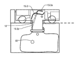
FIG. 14 shows a dust collection system of the present invention having a sprayer 19-1 for removing dust in the
図16は、掃除機内塵埃容器56内の塵埃を除去するための攪拌機を有する本発明の塵埃収集システムを示している。好ましくは、攪拌機は、長さ100mm・直径0.3mmの合成樹脂繊維の(10本の)束を有する。攪拌機は鞭のように動いて回転し、これによって、掃除機内塵埃容器56の内部の壁に付着する塵埃を取り除く。
FIG. 16 shows the dust collection system of the present invention having a stirrer for removing dust in the
図15は、掃除機内塵埃容器56内の塵埃を除去するための伸縮可能な回転吹きつけ機を有する本発明の塵埃収集システムを示している。伸縮可能な回転吹きつけ機19−2は、塵埃収集システム12内に設けられる。伸縮可能な回転吹きつけ機19−2は通常、格納された状態(図示せず)にある。吹きつけ回転子19−2aの一又は複数の穴からの気体を吹きつけるに際して、伸縮可能な回転吹きつけ機19−2は、長さが長くなるように伸びる。吹きつけ機を長く伸ばすために、吹きつけの気体の圧力を使用することができる。吹きつけ回転子19−2aは、吹きつけ機の軸を中心に回転することができる。気体が吹きつけ回転子19−2aから吹きつけられると、吹きつけ回転子19−2aは吹きつけられる気体によって発生する力に起因して回転する。塵埃容器56における大面積の壁を吹くことが可能になるので、回転吹きつけ機は望ましい。
Figure 1 5 shows a dust collection system of the present invention having a retractable rotary spray machine for removing dust in the vacuum
塵埃収集システム12及びロボット掃除機20における吹きつけ機、攪拌機及び振動機構等は、塵埃排出促進機構を構成する。
The
図6Aの多段サイクロン掃除機51における掃除機内塵埃容器56内の塵埃を取り除く回転吹きつけ機を備えた本発明の塵埃収集システムがある。塵埃容器56内の複雑な壁に起因して多段サイクロン掃除機51において塵埃を完全に排出することは難しいため、多段サイクロン掃除機においては、伸縮可能な回転吹きつけ機19−2bや他の塵埃排出促進機構が特に望ましい。
There is a dust collection system of the present invention provided with a rotary sprayer that removes dust in the
(15)留意事項
本発明の上記実施形態では、塵埃収集システム12、ロボット掃除機50及びそれらの構成部品のいくつかの実施形態を示した。組合せのすべてを本明細書に記載していないが、これらの要素の組合せはすべて本発明の実施形態を構成し、本明細書に組み込む。
(15) Points to Consider In the above embodiment of the present invention, several embodiments of the
Claims (15)
塵埃を格納するための塵埃容器と、
前記塵埃容器へ塵埃を収集するための塵埃入口と、
当該ロボット掃除機の底面に設けられ、前記塵埃容器に収集された塵埃を排出するための塵埃出口と、及び
塵埃の排出を促進する塵埃排出促進機構と
を有し、
前記塵埃排出促進機構は、前記塵埃排出ステーションへの塵埃の排出を支援するように前記塵埃出口が開いている塵埃の排出時に前記塵埃容器の内側の壁に内側から気体を吹きつけて前記塵埃排出ステーションへの塵埃の排出を促進する吹きつけ機である
ロボット掃除機。 A robot cleaner that can move autonomously to collect dust and discharge dust to a dust discharge station,
A dust container for storing dust;
A dust inlet for collecting dust in the dust container;
A dust outlet provided on the bottom surface of the robot cleaner, for discharging dust collected in the dust container, and a dust discharge promoting mechanism for promoting dust discharge;
The dust discharge promotion mechanism, said to assist the discharge of the dust dust outlet the dust discharge from said inner inside wall of the dust container by blowing gas in and upon the discharge of dust open to the dust discharge station Robot vacuum cleaner that is a spraying machine that promotes the discharge of dust to the station .
塵埃を格納するための塵埃容器と、
前記塵埃容器へ塵埃を収集するための塵埃入口と、
当該ロボット掃除機の底面に設けられ、前記塵埃容器に収集された塵埃を排出するための塵埃出口と、及び
塵埃の排出を促進する塵埃排出促進機構と
を有し、
前記塵埃排出促進機構は、前記塵埃排出ステーションへの塵埃の排出を支援するように前記塵埃出口が開いている塵埃の排出時に当該ロボット掃除機を振動させて前記塵埃排出ステーションへの塵埃の排出を促進する振動機構である
ロボット掃除機。 A robot cleaner that can move autonomously to collect dust and discharge dust to a dust discharge station,
A dust container for storing dust;
A dust inlet for collecting dust in the dust container;
A dust outlet provided on the bottom surface of the robot cleaner, for discharging dust collected in the dust container, and a dust discharge promoting mechanism for promoting dust discharge;
The dust discharge promoting mechanism vibrates the robot cleaner when discharging dust having an open dust outlet so as to support the discharge of dust to the dust discharge station to discharge the dust to the dust discharge station. Robot cleaner, a vibration mechanism that promotes.
塵埃を格納するための塵埃容器と、
前記塵埃容器へ塵埃を収集するための塵埃入口と、
当該ロボット掃除機の底面に設けられ、前記塵埃容器に収集された塵埃を排出するための塵埃出口と、及び
塵埃の排出を促進する塵埃排出促進機構と
を有し、
前記塵埃排出促進機構は、前記塵埃排出ステーションへの塵埃の排出を支援するように前記塵埃出口が開いている塵埃の排出時に前記塵埃容器内を可撓性の鞭状体を用いて攪拌して前記塵埃排出ステーションへの塵埃の排出を促進する攪拌機である
ロボット掃除機。 A robot cleaner that can move autonomously to collect dust and discharge dust to a dust discharge station,
A dust container for storing dust;
A dust inlet for collecting dust in the dust container;
A dust outlet provided on the bottom surface of the robot cleaner, for discharging dust collected in the dust container, and a dust discharge promoting mechanism for promoting dust discharge;
The dust discharge facilitating mechanism agitates the inside of the dust container using a flexible whip when discharging dust with the dust outlet open so as to support the discharge of dust to the dust discharge station. A robot cleaner which is a stirrer that promotes the discharge of dust to the dust discharge station .
前記吹きつけ機の吹きつけエネルギーは、前記ファンを前記負圧を生成するときとは逆の回転をさせることによって供給される
請求項1に記載のロボット掃除機。 A dust inlet and a fan for generating a negative pressure in the dust container in order to put dust into the dust container;
The robot cleaner according to claim 1 , wherein the blowing energy of the blowing machine is supplied by rotating the fan in a direction opposite to that when generating the negative pressure .
前記負圧を生成するときの気流の前記ファンよりも出口の側と前記塵埃容器との間に気体路とを有し、
前記吹きつけ機の吹きつけは、この気体路に前記ファンによって気体を流すことによって行われる
請求項1に記載のロボット掃除機。 A dust inlet for generating dust in the dust container and a fan for generating a negative pressure in the dust container; and
A gas path between the dust container and the outlet side of the airflow when generating the negative pressure;
The robot cleaner according to claim 1, wherein the spraying of the sprayer is performed by flowing a gas through the gas path with the fan .
請求項2に記載のロボット掃除機。 The robot cleaner according to claim 2, wherein the vibration mechanism vibrates the robot cleaner using a tire of the robot cleaner.
請求項1〜6のいずれかに記載のロボット掃除機。 The robot cleaner according to any one of claims 1 to 6, which autonomously moves to a dust discharge position in the dust discharge station.
を有する請求項1〜7のいずれかに記載のロボット掃除機。 The dust outlet has an opening / closing mechanism, and the opening / closing mechanism has a cover plate for covering the opening of the dust container and a closing rod for pushing the cover plate and closing the cover plate. The robot cleaner according to any one of the above.
を有する請求項1〜7のいずれかに記載のロボット掃除機。 The dust outlet has an opening / closing mechanism, and the opening / closing mechanism has a cover plate for covering the opening of the dust container and a rail guide for guiding the cover plate when the cover plate is opened and closed. The robot cleaner according to any one of the above.
を有する請求項1〜7及び9のいずれかに記載のロボット掃除機。 The dust outlet has an opening / closing mechanism, and the opening / closing mechanism has a cover plate for covering the opening of the dust container, and the cover plate is pulled and pushed to open and close the cover plate. The robot cleaner according to claim 1, having a member.
前記掃除機に対して台を提供し、前記掃除機を塵埃排出位置に配置するための掃除機用の台と、
前記掃除機用の台にて設けられ、前記塵埃排出位置で前記掃除機から塵埃を受けるように構成する塵埃受けと、
受けた塵埃を格納し前記塵埃受けの下に配置される使い捨て可能なプラスチック袋であるステーション内塵埃容器を保持し外すための容器ホルダーと、並びに
前記掃除機の塵埃容器内に気体を吹きつけて塵埃の収容を促進する吹きつけ機と、前記掃除機を振動させて塵埃の収容を促進する振動機構と、及び前記掃除機の塵埃容器内を撹拌して塵埃の収容を促進する攪拌機とからなる群より選択される塵埃排出促進機構と
を有し、
当該塵埃排出ステーションは、少なくとも重力に起因して、前記掃除機によって収集された塵埃を前記掃除機から受け、かつ、前記塵埃受けによって塵埃の経路を提供することによってステーション内塵埃容器の中へ塵埃を収容する
塵埃排出ステーション。 A dust discharge station capable of collecting dust from a vacuum cleaner,
Providing a base for the vacuum cleaner, and a base for the vacuum cleaner for placing the vacuum cleaner in a dust discharge position;
A dust receiver provided on the vacuum cleaner base and configured to receive dust from the vacuum cleaner at the dust discharge position;
A container holder for releasing holding station in dust container is received disposable plastic bag dust stores are located beneath the dust receiving, and
A blowing machine that blows gas into the dust container of the vacuum cleaner to promote the storage of dust, a vibration mechanism that vibrates the vacuum cleaner to promote the storage of dust, and the inside of the dust container of the vacuum cleaner A dust discharge facilitating mechanism selected from the group consisting of a stirrer that stirs and promotes dust storage ; and
The dust discharge station receives dust collected by the vacuum cleaner from the vacuum cleaner due to at least gravity, and provides a dust path by the dust receiver, thereby providing dust into the dust container in the station. Dust discharge station that accommodates.
前記掃除機に対して台を提供し、前記掃除機を塵埃排出位置に配置するための掃除機用の台と、
前記掃除機用の台にて設けられ、前記塵埃排出位置で前記掃除機から塵埃を受けるように構成する塵埃受けと、
受けた塵埃を格納する前記塵埃受けの下に配置されるステーション内塵埃容器を保持し外すための容器ホルダーと、並びに
前記掃除機の塵埃容器内に気体を吹きつけて塵埃の収容を促進する吹きつけ機と、前記掃除機を振動させて塵埃の収容を促進する振動機構と、及び前記掃除機の塵埃容器内を撹拌して塵埃の収容を促進する攪拌機とからなる群より選択される塵埃排出促進機構と
を有し、
当該塵埃排出ステーションは、少なくとも重力に起因して、吸引を行わない大気圧下で、前記掃除機によって収集された塵埃を前記掃除機から受け、かつ、前記塵埃受けによって塵埃の経路を提供することによってステーション内塵埃容器の中へ塵埃を収容する
塵埃排出ステーション。 A dust discharge station capable of collecting dust from a vacuum cleaner,
Providing a base for the vacuum cleaner, and a base for the vacuum cleaner for placing the vacuum cleaner in a dust discharge position;
A dust receiver provided on the vacuum cleaner base and configured to receive dust from the vacuum cleaner at the dust discharge position;
Received a container holder for removing holding station in the dust container is disposed below the dust receiving storing dust, and
A blowing machine that blows gas into the dust container of the vacuum cleaner to promote the storage of dust, a vibration mechanism that vibrates the vacuum cleaner to promote the storage of dust, and the inside of the dust container of the vacuum cleaner A dust discharge facilitating mechanism selected from the group consisting of a stirrer that stirs and promotes the storage of dust , and
The dust discharge station, due at least in gravity and atmospheric pressure is not performed Aspirate receives the dust collected by the cleaner from the cleaner, and provides a path of dust by the dust receiving A dust discharge station for storing dust in the dust container in the station.
を有する請求項11又は12に記載の塵埃排出ステーション。 The dust receiver has an opening / closing mechanism, and the opening / closing mechanism has a cover plate for covering the opening of the dust receiver, and a rail guide for guiding the cover plate when the cover plate is opened and closed. Item 13. The dust discharge station according to Item 11 or 12.
請求項11、12及び13のいずれかに記載の塵埃排出ステーション。 The dust receiver has an opening / closing mechanism, and the opening / closing mechanism has a cover plate for covering the opening of the dust receiver, and the cover plate is pulled / pressed to open and close the cover plate. 14. A dust discharge station according to any one of claims 11, 12 and 13, comprising a push tab.
前記ロボット掃除機から塵埃を収集することができる塵埃排出ステーションと
を有するロボット掃除機システム。 The robot cleaner according to any one of claims 1 to 10, and
A robot cleaner system comprising: a dust discharge station capable of collecting dust from the robot cleaner;
Priority Applications (1)
| Application Number | Priority Date | Filing Date | Title |
|---|---|---|---|
| JP2011168849A JP6010722B2 (en) | 2010-08-01 | 2011-08-01 | Robot vacuum cleaner, dust discharge station and multi-stage cyclone vacuum cleaner |
Applications Claiming Priority (2)
| Application Number | Priority Date | Filing Date | Title |
|---|---|---|---|
| US61/367723 | 2010-08-01 | ||
| JP2011168849A JP6010722B2 (en) | 2010-08-01 | 2011-08-01 | Robot vacuum cleaner, dust discharge station and multi-stage cyclone vacuum cleaner |
Publications (3)
| Publication Number | Publication Date |
|---|---|
| JP2012245344A JP2012245344A (en) | 2012-12-13 |
| JP2012245344A5 JP2012245344A5 (en) | 2015-07-02 |
| JP6010722B2 true JP6010722B2 (en) | 2016-10-19 |
Family
ID=47466360
Family Applications (1)
| Application Number | Title | Priority Date | Filing Date |
|---|---|---|---|
| JP2011168849A Expired - Fee Related JP6010722B2 (en) | 2010-08-01 | 2011-08-01 | Robot vacuum cleaner, dust discharge station and multi-stage cyclone vacuum cleaner |
Country Status (1)
| Country | Link |
|---|---|
| JP (1) | JP6010722B2 (en) |
Cited By (2)
| Publication number | Priority date | Publication date | Assignee | Title |
|---|---|---|---|---|
| CN108784520A (en) * | 2018-06-27 | 2018-11-13 | 杨扬 | The method that band embeds the dust-collecting robot of dirt box and establishes grating map |
| WO2021025377A1 (en) * | 2019-08-05 | 2021-02-11 | Samsung Electronics Co., Ltd. | Station of robot cleaner |
Families Citing this family (10)
| Publication number | Priority date | Publication date | Assignee | Title |
|---|---|---|---|---|
| JP6047406B2 (en) * | 2013-01-09 | 2016-12-21 | シャープ株式会社 | Self-propelled cleaner and self-propelled cleaner |
| JP6335050B2 (en) | 2014-07-04 | 2018-05-30 | 東芝ライフスタイル株式会社 | Electric vacuum cleaner |
| JP6411794B2 (en) | 2014-07-04 | 2018-10-24 | 東芝ライフスタイル株式会社 | Electric vacuum cleaner |
| JP6522905B2 (en) * | 2014-08-20 | 2019-05-29 | 東芝ライフスタイル株式会社 | Electric vacuum cleaner |
| KR20160023120A (en) | 2014-08-21 | 2016-03-03 | 삼성전자주식회사 | Robot cleaner |
| US9788698B2 (en) * | 2014-12-10 | 2017-10-17 | Irobot Corporation | Debris evacuation for cleaning robots |
| JP6463305B2 (en) * | 2016-07-19 | 2019-01-30 | シャープ株式会社 | Self-propelled cleaner and self-propelled cleaner |
| DE102019102382A1 (en) | 2019-01-30 | 2020-07-30 | Vorwerk & Co. Interholding Gmbh | Suction material collection station and system consisting of a suction material collection station and a suction cleaning device |
| CN113116214B (en) * | 2019-12-31 | 2024-04-02 | 江苏美的清洁电器股份有限公司 | Base assembly, cleaning device, ash pouring method and storage medium |
| AU2021232500A1 (en) * | 2020-03-03 | 2022-09-08 | Lg Electronics Inc. | Vacuum cleaner station, vacuum cleaner system, and method for controlling vacuum cleaner station |
Family Cites Families (10)
| Publication number | Priority date | Publication date | Assignee | Title |
|---|---|---|---|---|
| JPS61280818A (en) * | 1985-05-24 | 1986-12-11 | 三洋電機株式会社 | Automatic cleaning apparatus |
| BE1008470A3 (en) * | 1994-07-04 | 1996-05-07 | Colens Andre | Device and automatic system and equipment dedusting sol y adapted. |
| JP2001212052A (en) * | 2000-12-27 | 2001-08-07 | Matsushita Electric Ind Co Ltd | Electric vacuum cleaner |
| US20050150519A1 (en) * | 2002-07-08 | 2005-07-14 | Alfred Kaercher Gmbh & Co. Kg | Method for operating a floor cleaning system, and floor cleaning system for use of the method |
| JP4205466B2 (en) * | 2003-03-20 | 2009-01-07 | 日立アプライアンス株式会社 | Electric vacuum cleaner |
| JP2006087507A (en) * | 2004-09-21 | 2006-04-06 | Sanyo Electric Co Ltd | Self-propelled cleaner |
| JP2007125294A (en) * | 2005-11-07 | 2007-05-24 | Sharp Corp | Dust collector and vacuum cleaner including the same |
| EP2548489B1 (en) * | 2006-05-19 | 2016-03-09 | iRobot Corporation | Removing debris from cleaning robots |
| KR101339513B1 (en) * | 2007-05-09 | 2013-12-10 | 아이로보트 코퍼레이션 | Autonomous coverage robot |
| JP2009011616A (en) * | 2007-07-06 | 2009-01-22 | Panasonic Corp | Electric vacuum cleaner |
-
2011
- 2011-08-01 JP JP2011168849A patent/JP6010722B2/en not_active Expired - Fee Related
Cited By (3)
| Publication number | Priority date | Publication date | Assignee | Title |
|---|---|---|---|---|
| CN108784520A (en) * | 2018-06-27 | 2018-11-13 | 杨扬 | The method that band embeds the dust-collecting robot of dirt box and establishes grating map |
| WO2021025377A1 (en) * | 2019-08-05 | 2021-02-11 | Samsung Electronics Co., Ltd. | Station of robot cleaner |
| US11452418B2 (en) | 2019-08-05 | 2022-09-27 | Samsung Electronics Co., Ltd. | Station of robot cleaner |
Also Published As
| Publication number | Publication date |
|---|---|
| JP2012245344A (en) | 2012-12-13 |
Similar Documents
| Publication | Publication Date | Title |
|---|---|---|
| JP6010722B2 (en) | Robot vacuum cleaner, dust discharge station and multi-stage cyclone vacuum cleaner | |
| US9192272B2 (en) | Robot cleaner and dust discharge station | |
| US7776120B2 (en) | Vacuum cleaner with a moveable divider plate | |
| US20200178742A1 (en) | Electric vacuum cleaner and electric vacuum cleaning apparatus | |
| CN111904323B (en) | Dust deposition base and cleaning equipment assembly with same | |
| JP6707341B2 (en) | Electric cleaning device | |
| CN209953473U (en) | Cleaning device and cleaning device assembly |
Legal Events
| Date | Code | Title | Description |
|---|---|---|---|
| A521 | Written amendment |
Free format text: JAPANESE INTERMEDIATE CODE: A523 Effective date: 20121001 |
|
| A521 | Written amendment |
Free format text: JAPANESE INTERMEDIATE CODE: A523 Effective date: 20140808 |
|
| A621 | Written request for application examination |
Free format text: JAPANESE INTERMEDIATE CODE: A621 Effective date: 20140801 |
|
| A521 | Written amendment |
Free format text: JAPANESE INTERMEDIATE CODE: A523 Effective date: 20141108 |
|
| A521 | Written amendment |
Free format text: JAPANESE INTERMEDIATE CODE: A523 Effective date: 20141128 |
|
| A621 | Written request for application examination |
Free format text: JAPANESE INTERMEDIATE CODE: A621 Effective date: 20140801 |
|
| A521 | Written amendment |
Free format text: JAPANESE INTERMEDIATE CODE: A523 Effective date: 20150509 |
|
| A977 | Report on retrieval |
Free format text: JAPANESE INTERMEDIATE CODE: A971007 Effective date: 20150708 |
|
| A131 | Notification of reasons for refusal |
Free format text: JAPANESE INTERMEDIATE CODE: A131 Effective date: 20150818 |
|
| A521 | Written amendment |
Free format text: JAPANESE INTERMEDIATE CODE: A523 Effective date: 20151019 |
|
| TRDD | Decision of grant or rejection written | ||
| A01 | Written decision to grant a patent or to grant a registration (utility model) |
Free format text: JAPANESE INTERMEDIATE CODE: A01 Effective date: 20151110 |
|
| A61 | First payment of annual fees (during grant procedure) |
Free format text: JAPANESE INTERMEDIATE CODE: A61 Effective date: 20151210 |
|
| R150 | Certificate of patent or registration of utility model |
Ref document number: 6010722 Country of ref document: JP Free format text: JAPANESE INTERMEDIATE CODE: R150 |
|
| LAPS | Cancellation because of no payment of annual fees |